Embed Size (px)
Citation preview

Aspire T180/E380AcerPower M8
Service Guide
PRINTED IN TAIWAN
Service guide files and updates are availableon the AIPG/CSD web; for more information,
please refer to http://csd.acer.com.tw

Revision HistoryPlease refer to the table below for the updates made on Aspire T180/E380 and AcerPower M8 service guide.
Date Chapter Updates
II
CopyrightCopyright © 2006 by Acer Incorporated. All rights reserved. No part of this publication may be reproduced, transmitted, transcribed, stored in a retrieval system, or translated into any language or computer language, in any form or by any means, electronic, mechanical, magnetic, optical, chemical, manual or otherwise, without the prior written permission of Acer Incorporated.
DisclaimerThe information in this guide is subject to change without notice.
Acer Incorporated makes no representations or warranties, either expressed or implied, with respect to the contents hereof and specifically disclaims any warranties of merchantability or fitness for any particular purpose. Any Acer Incorporated software described in this manual is sold or licensed "as is". Should the programs prove defective following their purchase, the buyer (and not Acer Incorporated, its distributor, or its dealer) assumes the entire cost of all necessary servicing, repair, and any incidental or consequential damages resulting from any defect in the software.
Acer is a registered trademark of Acer Corporation.Intel is a registered trademark of Intel Corporation.Pentium 4 and Celeron are trademarks of Intel Corporation.Other brand and product names are trademarks and/or registered trademarks of their respective holders.
III
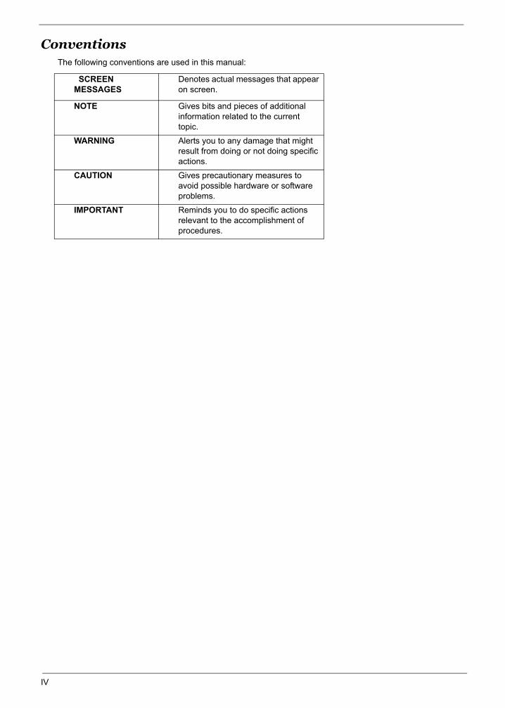
ConventionsThe following conventions are used in this manual:
SCREEN MESSAGES
Denotes actual messages that appear on screen.
NOTE Gives bits and pieces of additional information related to the current topic.
WARNING Alerts you to any damage that might result from doing or not doing specific actions.
CAUTION Gives precautionary measures to avoid possible hardware or software problems.
IMPORTANT Reminds you to do specific actions relevant to the accomplishment of procedures.
IV

PrefaceBefore using this information and the product it supports, please read the following general information.
1. This Service Guide provides you with all technical information relating to the BASIC CONFIGURATION decided for Acer's "global" product offering. To better fit local market requirements and enhance product competitiveness, your regional office MAY have decided to extend the functionality of a machine (e.g. add-on card, modem, or extra memory capability). These LOCALIZED FEATURES will NOT be covered in this generic service guide. In such cases, please contact your regional offices or the responsible personnel/channel to provide you with further technical details.
2. Please note WHEN ORDERING FRU PARTS, that you should check the most up-to-date information available on your regional web or channel. If, for whatever reason, a part number change is made, it will not be noted in the printed Service Guide. For ACER-AUTHORIZED SERVICE PROVIDERS, your Acer office may have a DIFFERENT part number code to those given in the FRU list of this printed Service Guide. You MUST use the list provided by your regional Acer office to order FRU parts for repair and service of customer machines.
V
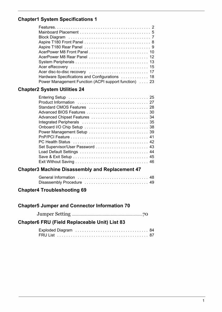
Chapter1 System Specifications 1Features. . . . . . . . . . . . . . . . . . . . . . . . . . . . . . . . . . . . . . . . . . 2Mainboard Placement . . . . . . . . . . . . . . . . . . . . . . . . . . . . . . . 5Block Diagram . . . . . . . . . . . . . . . . . . . . . . . . . . . . . . . . . . . . 7Aspire T180 Front Panel . . . . . . . . . . . . . . . . . . . . . . . . . . . . . 8Aspire T180 Rear Panel . . . . . . . . . . . . . . . . . . . . . . . . . . . . . 9AcerPower M8 Front Panel . . . . . . . . . . . . . . . . . . . . . . . . . . 10AcerPower M8 Rear Panel . . . . . . . . . . . . . . . . . . . . . . . . . . 12System Peripherals . . . . . . . . . . . . . . . . . . . . . . . . . . . . . . . . 13Acer eRecovery . . . . . . . . . . . . . . . . . . . . . . . . . . . . . . . . . . 15Acer disc-to-disc recovery . . . . . . . . . . . . . . . . . . . . . . . . . . 17Hardware Specifications and Configurations . . . . . . . . . . . . 18Power Management Function (ACPI support function) . . . . 23
Chapter2 System Utilities 24Entering Setup . . . . . . . . . . . . . . . . . . . . . . . . . . . . . . . . . . . 25Product Information . . . . . . . . . . . . . . . . . . . . . . . . . . . . . . . 27Standard CMOS Features . . . . . . . . . . . . . . . . . . . . . . . . . . 28Advanced BIOS Features . . . . . . . . . . . . . . . . . . . . . . . . . . . 30Advanced Chipset Features . . . . . . . . . . . . . . . . . . . . . . . . . 34Integrated Peripherals . . . . . . . . . . . . . . . . . . . . . . . . . . . . . 35Onboard I/O Chip Setup . . . . . . . . . . . . . . . . . . . . . . . . . . . . 38Power Management Setup . . . . . . . . . . . . . . . . . . . . . . . . . . 39PnP/PCI Feature . . . . . . . . . . . . . . . . . . . . . . . . . . . . . . . . . . 41PC Health Status . . . . . . . . . . . . . . . . . . . . . . . . . . . . . . . . . 42Set Supervisor/User Password . . . . . . . . . . . . . . . . . . . . . . . 43Load Default Settings . . . . . . . . . . . . . . . . . . . . . . . . . . . . . . 44Save & Exit Setup . . . . . . . . . . . . . . . . . . . . . . . . . . . . . . . . . 45Exit Without Saving . . . . . . . . . . . . . . . . . . . . . . . . . . . . . . . . 46
Chapter3 Machine Disassembly and Replacement 47General Information . . . . . . . . . . . . . . . . . . . . . . . . . . . . . . . 48Disassembly Procedure . . . . . . . . . . . . . . . . . . . . . . . . . . . . 49
Chapter4 Troubleshooting 69
Chapter5 Jumper and Connector Information 70 Jumper Setting ..............................................................70
Chapter6 FRU (Field Replaceable Unit) List 83Exploded Diagram . . . . . . . . . . . . . . . . . . . . . . . . . . . . . . . . 84FRU List . . . . . . . . . . . . . . . . . . . . . . . . . . . . . . . . . . . . . . . . 87
1
System Specifications
Chapter 1
OverviewThe model is a consumer/commercial-oriented desktop PC built with latest, high-performance technology for
easier and funnier consumer environment. It is a high performance and multi-media features ready system
including Media Card Reader and Rear I/O connectors for 7.1 audio channels.
Regarding the high performance, we choose AMD Athlon 64 X2/Athlon64/Sempron (AM2 Socket), with
NVIDIA MCP61 chipset architecture. This combination can run HyperTransport technology and provide On-
Board VGA, which provides better performance than other processors. We also provide one PCI-Express x16
slot, one PCI-Express x1 and two PCI slots (support PCI 2.3 spec.), four Dual Channel DDRII memory slots
(support up to 4GB), two PATA ports, two/four SATA ports (HDDs), on board Gigabit LAN, and on board Audio
function.
Chapter 1 1
Features
Processor
Socket Type : 940 pin socket
Processor Type : AMD AM2 Athlon64 x2/Athlon64/Sempron
Chipset
nVidia MCP61S (co-lay with MCP61P)
PCB
Form Factor : Mirco ATX
Size (Max.) : 244mm x 244mm
MemoryMemory Type : DDRII unbuffered SDRAM module support
No of Channel (Dual/Signal) : Dual channel should be enabled always when plug-in 2 same memory size DDRII memory module
Socket Type : un-buffered 240 pin DIMM socket
DIMM Slot : 4
Memorry Size Max. : Up to 1 GB
Graphics
Onboard graphic solution: nVidia MCP61 integrated graphics device solution
One VGA port on rear
PCI
One PCI Express x16 slot
One PCI Express x1 slot
Two PCI 2.2 Slots
FDD
Slot Quantity : 1
Support 1.44MB 3.5” Devices
IDE
One 40 pin PATA IDE slot
Transfer rate support:
PIO mode: 0/1/2/3/4
ATA mode: 33/66/100 port supported
Storage type support : HDD/CD-ROM/CD-RW/DVD-ROM/DVD-RW/DVD+RW/DVD Dual/DVD SuperMultiPlus/HD DVD/BlueRay DVD
4 pin SATA IDE connector
Transfer rate support:
1.5GB/s and 3.0 GB/s
Storage type support : HDD/CD-ROM/DVD-ROM/DVD-RW/DVD+RW/DVD Dual/DVD SuperMultiPlus
2 Chapter 1
Audio
Audio Type : HD Codec
Audio Channel : 7.1 channel
Audio Controller /Codec : Realtek ALC888(co-lay with ALC883)
Support SPDIF out/in
Audio Connectors/Headers:
Rear 6 jack follow HD audio definition
Microphone In
Headphone Out
CD-In
LAN
Type : Marvell 88E8056 Gigabit Ethernet controller
Supports 10/100/1000MB Ethernet environment
IEEE 1394
IEEE 1394 Controller : TI TSB43AB23PDTG4
IEEE 1394 Port : One rear 6pin IEEE 1394 port
USB
Controller : nVidia MCP61
USB Type : 2.0/1.1
Connectors Quantity: 8
Real Panel : 4
Onboard header: 4 for front daughter board, 4 for rear I/O
Standard Intel FPIO pin definition
BIOS
BIOS Type : Award BIOS
4MB Flash BIOS
Award PnP BIOS compatible with SM BIOS 2.3
ACPI, SMBIOS 2.3, Green and Boot Block.
Provides DMI 2.0, WFM 2.0, WOL, and SM Bus for system management.
Chapter 1 3
4 Chapter 1
I/O Connector
Controller : Super I/O ITE 8726 co-lay with ITE8716
Rear I/O Connector
1 PS/2 Keyboard Port, 1 PS/2 Mouse Port
1 Parallel Port, 1 Serial Port
1 VGA(CRT) Port
1 LAN Port
4 USB Ports for non-1394 sku; 4 USB ports + IEEE1394 port for 1394 sku
7.1 channel phone jack
Onboard Connector
1 CPU socket
4 Memory slots
1 PCI Express x16 slot
1 PCI Express x1 slot
2 PCI slots
1 FDD connector
1 PATA IDE slot
2/4 SATA IDE connectors
2/3 2*5 pin Intel FPIO sepcification USB pin connectors.
1 2*5 pin IEEE 1394 jumper
1 CD-IN 4pin connector (CD-ROM/TV Tuner Card Audio Input)
1 S/PDIF out 3pin jumper
1 4pin CPU Fan connector
1 4pin system fan connector with 3pin system fan co-lay
1 24pin ATX interface PS3/PS2 SPS connector
1 2*7 pin front panel IO header
2 reserved 2pin GPIO jumper
1 onboard buzzer
Color management for on board connecter
Power Supply
PSP Type : 250/300W
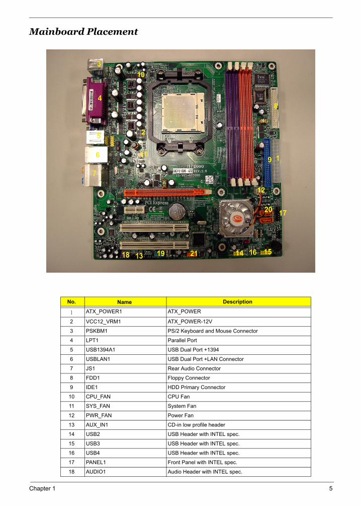
Mainboard Placement
No. Name Description
1 ATX_POWER1 ATX_POWER
2 VCC12_VRM1 ATX_POWER-12V
3 PSKBM1 PS/2 Keyboard and Mouse Connector
4 LPT1 Parallel Port
5 USB1394A1 USB Dual Port +1394
6 USBLAN1 USB Dual Port +LAN Connector
7 JS1 Rear Audio Connector
8 FDD1 Floppy Connector
9 IDE1 HDD Primary Connector
10 CPU_FAN CPU Fan
11 SYS_FAN System Fan
12 PWR_FAN Power Fan
13 AUX_IN1 CD-in low profile header
14 USB2 USB Header with INTEL spec.
15 USB3 USB Header with INTEL spec.
16 USB4 USB Header with INTEL spec.
17 PANEL1 Front Panel with INTEL spec.
18 AUDIO1 Audio Header with INTEL spec.
Chapter 1 5
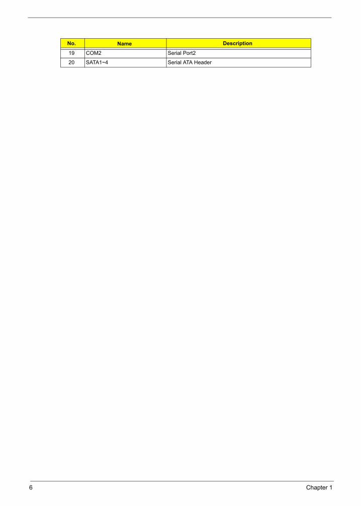
19 COM2 Serial Port2
20 SATA1~4 Serial ATA Header
No. Name Description
6 Chapter 1
Chapter 1 7
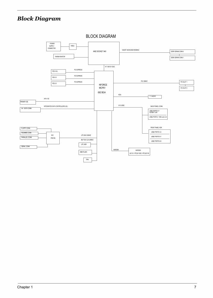
Block Diagram
USB2 PORTS / 1394 conn 2-3
USB2 PORTS 0-1
USB2 PORTS 6-7
128-BIT 400/533/667/800MHZ
HT 16X16 1GHZ
INTEGRATED SATA CONTROLLERS (X2)
PEX X16
ATA 133
PEX X1
FRONT PANEL HDR
LPC HDR
THERM MONITOR
PCI EXPRESS
TPM
X10 USB2
HDA
4MB FLASH
USB2 PORTS 4-5
DDRII SDRAM CONN 1
PCI 33MHZ
SUPPLY
MII/RGMII
BACK PANEL CONN
VREG
MII/RGMII
AC131 / RTL8110SC / RTL8211B
DDRII SDRAM CONN 0
7.1 AUDIO
LPC BUS 33MHZ
PCI SLOT 2
PCI SLOT 1
PRIMARY IDE
X4 - SATA CONN
SIO
PS2/KBRD CONN
PARALLEL CONN
CONNECTOR
ITE8726
FLOPPY CONN
SERIAL CONN
POWER
X2/GBIT LAN
BLOCK DIAGRAM
AM2 SOCKET 940
NFORCE
MCP61
692 BGA
PCI EXPRESS
BUF SIO CLK 24MHZUSB2 PORTS 8-9
PEX X1 PCI EXPRESS
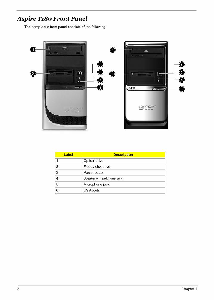
Aspire T180 Front PanelThe computer’s front panel consists of the following:
Label Description1 Optical drive
2 Floppy disk drive
3 Power button
4 Speaker or headphone jack
5 Microphone jack
6 USB ports
No. Description No. Description
8 Chapter 1
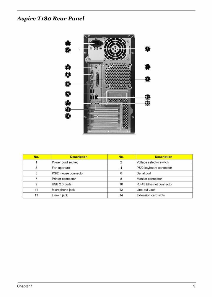
Aspire T180 Rear Panel
No. Description No. Description
1 Power cord socket 2 Voltage selector switch
3 Fan aperture 4 PS/2 keyboard connector
5 PS/2 mouse connector 6 Serial port
7 Printer connector 8 Monitor connector
9 USB 2.0 ports 10 RJ-45 Ethernet connector
11 Microphone jack 12 Line-out Jack
13 Line-in jack 14 Extension card slots
No. Description No. Description
Chapter 1 9
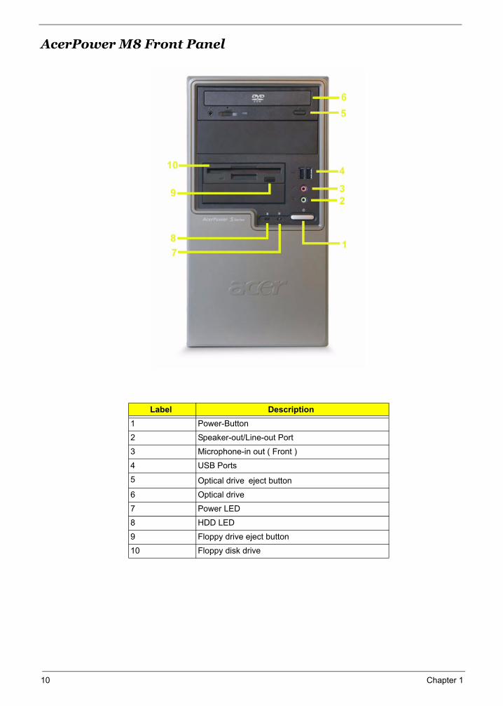
AcerPower M8 Front Panel
Label Description1 Power-Button
2 Speaker-out/Line-out Port
3 Microphone-in out ( Front )
4 USB Ports
5 Optical drive eject button
6 Optical drive
7 Power LED
8 HDD LED
9 Floppy drive eject button
10 Floppy disk drive
10 Chapter 1
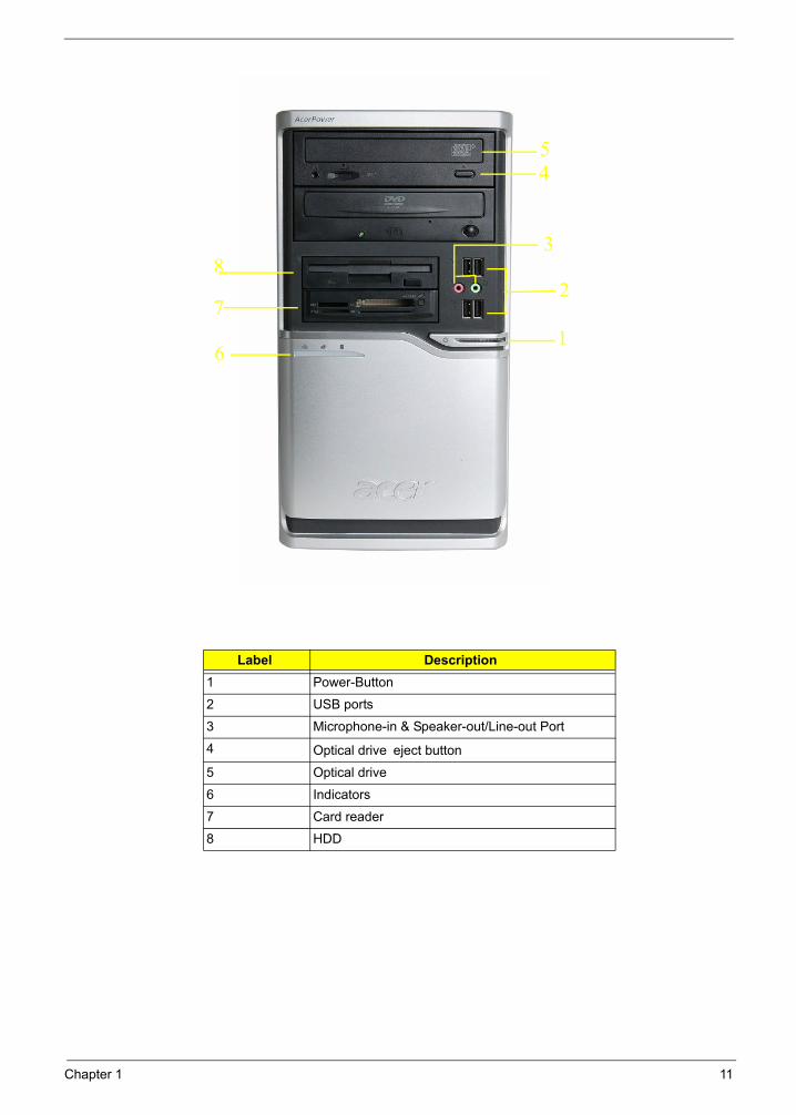
Label Description1 Power-Button
2 USB ports
3 Microphone-in & Speaker-out/Line-out Port
4 Optical drive eject button
5 Optical drive
6 Indicators
7 Card reader
8 HDD
1
2
3
45
6
7
8
Chapter 1 11
12 Chapter 1
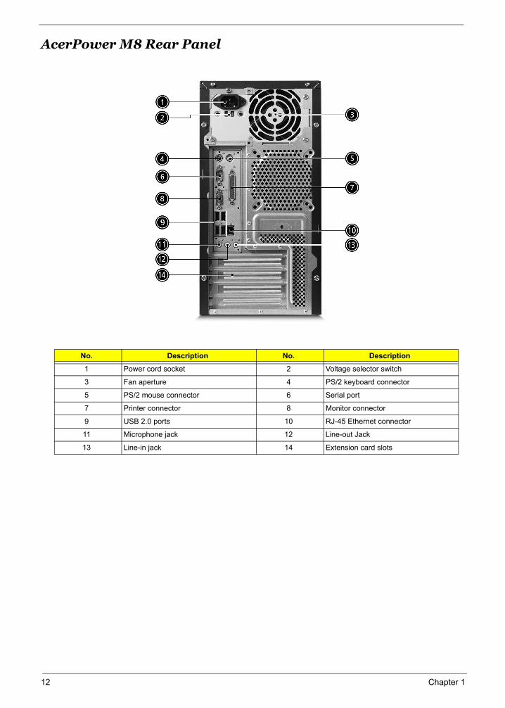
AcerPower M8 Rear Panel
No. Description No. Description
1 Power cord socket 2 Voltage selector switch
3 Fan aperture 4 PS/2 keyboard connector
5 PS/2 mouse connector 6 Serial port
7 Printer connector 8 Monitor connector
9 USB 2.0 ports 10 RJ-45 Ethernet connector
11 Microphone jack 12 Line-out Jack
13 Line-in jack 14 Extension card slots
No. Description No. Description
Chapter 1 13
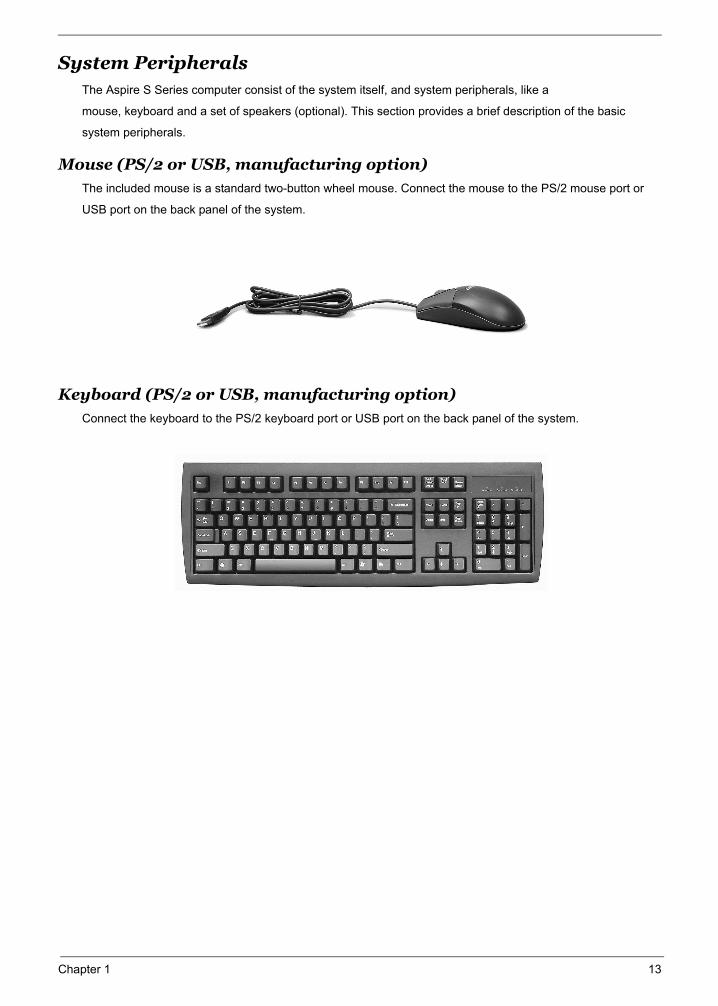
System Peripherals The Aspire S Series computer consist of the system itself, and system peripherals, like a
mouse, keyboard and a set of speakers (optional). This section provides a brief description of the basic
system peripherals.
Mouse (PS/2 or USB, manufacturing option)
The included mouse is a standard two-button wheel mouse. Connect the mouse to the PS/2 mouse port or
USB port on the back panel of the system.
Keyboard (PS/2 or USB, manufacturing option)
Connect the keyboard to the PS/2 keyboard port or USB port on the back panel of the system.
14 Chapter 1
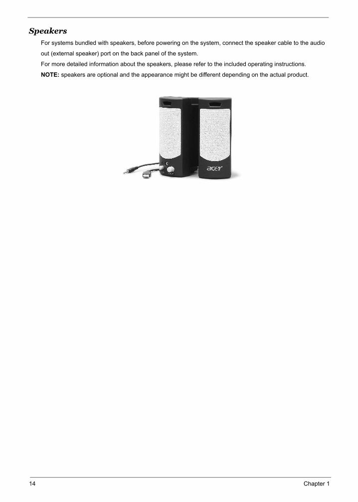
SpeakersFor systems bundled with speakers, before powering on the system, connect the speaker cable to the audio
out (external speaker) port on the back panel of the system.
For more detailed information about the speakers, please refer to the included operating instructions.
NOTE: speakers are optional and the appearance might be different depending on the actual product.
Note:
Acer eRecoveryAcer eRecovery is a tool to quickly backup and restore the system. Users can create and save a
backup of the current system configuration to hard drive, CD, or DVD.
Acer eRecovery consists of the following functions:
1. Create backup
2. Restore from backup
3. Create factory default image CD
4. Re-install bundled software without CD
5. Change Acer eRecovery password
Create backup
Users can create and save backup images to hard drive, CD, or DVD.
1. Boot to Windows XP
2. Press <Alt>+<F10> to open the Acer eRecovery utility.
3. Enter the password to proceed. The default password is six zeros.
4. In the Acer eRecovery window, select Recovery settings and click Next
5. In the Recovery settings window, select Backup snapshot image and click Next.
6. Select the backup method.
Use Backup to HDD to store the backup disc image on drive D:.
Backup to optical device to store the backup disc image on CD or DVD (only available on
systems that include an optical disc burner).
7. After choosing the backup method, click Next.
Follow the instruction on screen to complete the process.
Restore from backup
Users can restore backup previously created (as stated in the Create backup section) from hard drive,
CD, or DVD.
1. Boot to Windows XP.
2. Press <Alt>+<F10> to open the Acer eRecovery utility.
3. Enter the password to proceed. The default password is six zeros.
4. In the Acer eRecovery window, select Recovery actions and click Next.
5. Select the desired restore action and follow the onscreen instructions to complete the restore process.
Create factory default image CD
When the System CD and Recovery CD are not available, you can create them by using this feature.
1. Boot to Windows XP.
2. Press <Alt>+<F10> to open the Acer eRecovery utility.
3. Enter the password to proceed. The default password is six zeros.
4. In the Acer eRecovery window, select Recovery settings and click Next.
5. In the Recovery settings window, select Burn image to disc and click Next.
6. In the Burn image to disc window, select 01. Factory default image and click Next.
Chapter 1 15
7. Follow the instructions on screen to complete the process.
Re-install bundled software without CD
Acer eRecovery stores pre-loaded software internally for easy driver and application re-installation.
1. Boot to Windows XP.
2. Press <Alt>+<F10> to open the Acer eRecovery utility.
3. Enter the password to proceed. The default password is six zeros.
4. In the Acer eRecovery window, select Recovery actions and click Next.
5. In the Recovery settings window, select Reinstall applications/drivers and click Next.
6. Select the desired driver/application and follow the instructions on screen to re-install.
At first launch, Acer eRecovery prepares all the needed software and may take few seconds to bring up the
software content window.
Change PasswordAcer eRecovery and Acer disc-to-disc recovery are protected by a password that can be changed by
the user. Follow the steps below to change the password in Acer eRecovery.
1. Boot to Windows XP.
2. Press <Alt>+<F10> to open the Acer eRecovery utility.
3. Enter the password to proceed. The default password is six zeros.
4. In the Acer eRecovery window, select Recovery settings and click Next.
5. In the Recovery settings window, select Password: Change Acer eRecovery password and click Next.
6. Follow the instructions on screen to complete the process.
16 Chapter 1
Acer disc-to-disc recovery
Restore without a Recovery CD
This recovery process helps you restore the C: drive with the original software content that is installed when
you purchase your notebook. Follow the steps below to rebuild your C: drive. (Your C: drive will be
reformatted and all data will be erased.) It is important to back up all data files before you use this option.
1. Restart the system.
2. While the Acer logo is showing, press <Alt>+<F10> at the same time to enter the recovery process.
3. The message "The system has password protection. Please enter 000000:" is displayed.
4. Enter six zeros and continue.
5. The Acer Recovery main page appears.
6. Use the arrow keys to scroll through the items (operating system versions) and press <Enter> to select.
Multilingual operating system installation
Follow the instructions to choose the operating system and language you prefer when you first power-on the
system.
1. Turn on the system.
2. Acer's multilingual operating system selection menu will pop-up automatically.
3. Use the arrow keys to scroll to the language version you want. Press <Enter> to confirm your selection.
4. The operating system and language you choose now will be the only option for future recovery operations.
5. The system will install the operating system and language you choose.
Chapter 1 17
18 Chapter 1
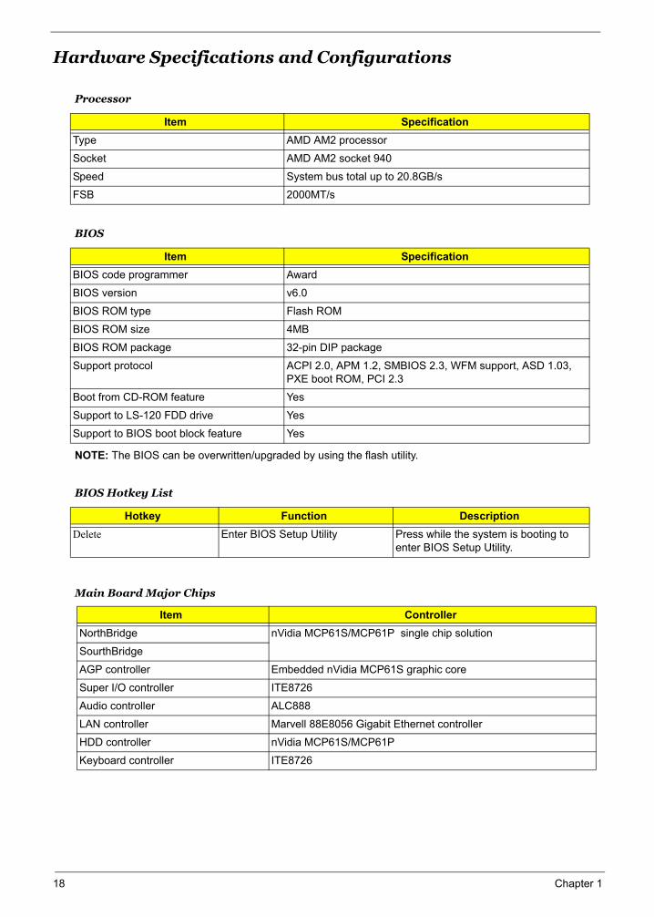
Hardware Specifications and Configurations
NOTE: The BIOS can be overwritten/upgraded by using the flash utility.
Main Board Major Chips
Processor
Item SpecificationType AMD AM2 processor
Socket AMD AM2 socket 940
Speed System bus total up to 20.8GB/s
FSB 2000MT/s
BIOS
Item SpecificationBIOS code programmer Award
BIOS version v6.0
BIOS ROM type Flash ROM
BIOS ROM size 4MB
BIOS ROM package 32-pin DIP package
Support protocol ACPI 2.0, APM 1.2, SMBIOS 2.3, WFM support, ASD 1.03, PXE boot ROM, PCI 2.3
Boot from CD-ROM feature Yes
Support to LS-120 FDD drive Yes
Support to BIOS boot block feature Yes
BIOS Hotkey List
Hotkey Function DescriptionDelete Enter BIOS Setup Utility Press while the system is booting to
enter BIOS Setup Utility.
Item ControllerNorthBridge nVidia MCP61S/MCP61P single chip solution
SourthBridge
AGP controller Embedded nVidia MCP61S graphic core
Super I/O controller ITE8726
Audio controller ALC888
LAN controller Marvell 88E8056 Gigabit Ethernet controller
HDD controller nVidia MCP61S/MCP61P
Keyboard controller ITE8726
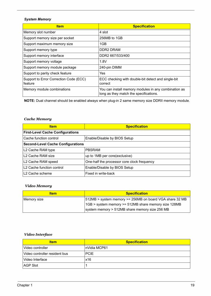
System Memory
NOTE: Dual channel should be enabled always when plug-in 2 same memory size DDRII memory module.
Item SpecificationMemory slot number 4 slot
Support memory size per socket 256MB to 1GB
Support maximum memory size 1GB
Support memory type DDR2 DRAM
Support memory interface DDR2 667/533/400
Support memory voltage 1.8V
Support memory module package 240-pin DIMM
Support to parity check feature Yes
Support to Error Correction Code (ECC) feature
ECC checking with double-bit detect and single-bit correct
Memory module combinations You can install memory modules in any combination as long as they match the specifications.
Cache Memory
Item SpecificationFirst-Level Cache ConfigurationsCache function control Enable/Disable by BIOS Setup
Second-Level Cache ConfigurationsL2 Cache RAM type PBSRAM
L2 Cache RAM size up to 1MB per core(exclusive)
L2 Cache RAM speed One-half the processor core clock frequency
L2 Cache function control Enable/Disable by BIOS Setup
L2 Cache scheme Fixed in write-back
Video Memory
Item SpecificationMemory size 512MB > system memory >= 256MB on board VGA share 32 MB
1GB > system memory >= 512MB share memory size 128MBsystem memory > 512MB share memory size 256 MB
Video Interface
Item SpecificationVideo controller nVidia MCP61
Video controller resident bus PCIE
Video Interface x16
AGP Slot 1
Chapter 1 19
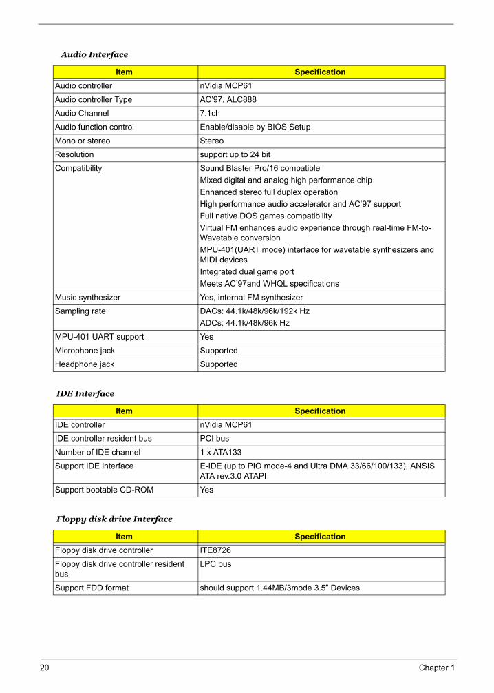
Audio Interface
Item SpecificationAudio controller nVidia MCP61
Audio controller Type AC’97, ALC888
Audio Channel 7.1ch
Audio function control Enable/disable by BIOS Setup
Mono or stereo Stereo
Resolution support up to 24 bit
Compatibility Sound Blaster Pro/16 compatibleMixed digital and analog high performance chipEnhanced stereo full duplex operationHigh performance audio accelerator and AC’97 supportFull native DOS games compatibilityVirtual FM enhances audio experience through real-time FM-to-Wavetable conversionMPU-401(UART mode) interface for wavetable synthesizers and MIDI devicesIntegrated dual game portMeets AC’97and WHQL specifications
Music synthesizer Yes, internal FM synthesizer
Sampling rate DACs: 44.1k/48k/96k/192k HzADCs: 44.1k/48k/96k Hz
MPU-401 UART support Yes
Microphone jack Supported
Headphone jack Supported
IDE Interface
Item SpecificationIDE controller nVidia MCP61
IDE controller resident bus PCI bus
Number of IDE channel 1 x ATA133
Support IDE interface E-IDE (up to PIO mode-4 and Ultra DMA 33/66/100/133), ANSIS ATA rev.3.0 ATAPI
Support bootable CD-ROM Yes
Floppy disk drive Interface
Item SpecificationFloppy disk drive controller ITE8726
Floppy disk drive controller resident bus
LPC bus
Support FDD format should support 1.44MB/3mode 3.5” Devices
20 Chapter 1
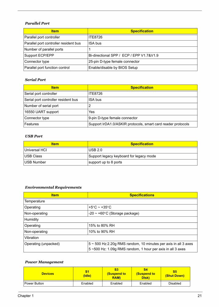
Parallel Port
Item SpecificationParallel port controller ITE8726
Parallel port controller resident bus ISA bus
Number of parallel ports 1
Support ECP/EPP Bi-directional SPP / ECP / EPP V1.7&V1.9
Connector type 25-pin D-type female connector
Parallel port function control Enable/disable by BIOS Setup
Serial Port
Item SpecificationSerial port controller ITE8726
Serial port controller resident bus ISA bus
Number of serial port 2
16550 UART support Yes
Connector type 9-pin D-type female connector
Features Support IrDA1.0/ASKIR protocols, smart card reader protocols
USB Port
Item SpecificationUniversal HCI USB 2.0
USB Class Support legacy keyboard for legacy mode
USB Number support up to 8 ports
Environmental Requirements
Item SpecificationsTemperature
Operating +5°C ~ +35°C
Non-operating -20 ~ +60°C (Storage package)
Humidity
Operating 15% to 80% RH
Non-operating 10% to 90% RH
Vibration
Operating (unpacked) 5 ~ 500 Hz:2.20g RMS random, 10 minutes per axis in all 3 axes5 ~500 Hz: 1.09g RMS random, 1 hour per axis in all 3 axes
Power Management
Devices S1(Idle)
S3(Suspend to
RAM)
S4(Suspend to
DIsk)
S5(Shut Down)
Power Button Enabled Enabled Enabled Disabled
Chapter 1 21

USB Keyboard Enabled Enabled Disabled N/A
LAN Disabled Disabled Disabled Disabled
RTC Disabled Enabled Disabled Disabled
Modem (Ring) Disabled Disabled Disabled N/A
Power Management
Devices S1(Idle)
S3(Suspend to
RAM)
S4(Suspend to
DIsk)
S5(Shut Down)
22 Chapter 1
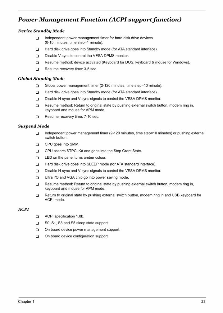
Power Management Function (ACPI support function)
Device Standby Mode
Independent power management timer for hard disk drive devices (0-15 minutes, time step=1 minute).
Hard disk drive goes into Standby mode (for ATA standard interface).
Disable V-sync to control the VESA DPMS monitor.
Resume method: device activated (Keyboard for DOS, keyboard & mouse for Windows).
Resume recovery time: 3-5 sec.
Global Standby Mode
Global power management timer (2-120 minutes, time step=10 minute).
Hard disk drive goes into Standby mode (for ATA standard interface).
Disable H-sync and V-sync signals to control the VESA DPMS monitor.
Resume method: Return to original state by pushing external switch button, modem ring in, keyboard and mouse for APM mode.
Resume recovery time: 7-10 sec.
Suspend Mode
Independent power management timer (2-120 minutes, time step=10 minutes) or pushing external switch button.
CPU goes into SMM.
CPU asserts STPCLK# and goes into the Stop Grant State.
LED on the panel turns amber colour.
Hard disk drive goes into SLEEP mode (for ATA standard interface).
Disable H-sync and V-sync signals to control the VESA DPMS monitor.
Ultra I/O and VGA chip go into power saving mode.
Resume method: Return to original state by pushing external switch button, modem ring in, keyboard and mouse for APM mode.
Return to original state by pushing external switch button, modem ring in and USB keyboard for ACPI mode.
ACPI
ACPI specification 1.0b.
S0, S1, S3 and S5 sleep state support.
On board device power management support.
On board device configuration support.
Chapter 1 23

24 Chapter 1
System Utilities
Chapter 2
Most systems are already configured by the manufacturer or the dealer. There is no need to run Setup when starting the computer unless you get a Run Setup message. The Setup program loads configuration values into the battery-backed nonvolatile memory called CMOS RAM. This memory area is not part of the system RAM.
NOTE: If you repeatedly receive Run Setup messages, the battery may be bad/flat. In this case, the system cannot retain configuration values in CMOS.
Before you run Setup, make sure that you have saved all open files. The system reboots immediately after you exit Setup.
Chapter 2 24
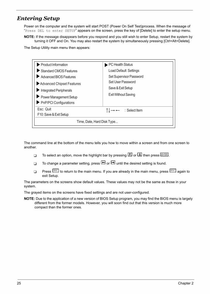
Entering SetupPower on the computer and the system will start POST (Power On Self Test)process. When the message of “Press DEL to enter SETUP” appears on the screen, press the key of [Delete] to enter the setup menu.
NOTE: If the message disappears before you respond and you still wish to enter Setup, restart the system by turning it OFF and On. You may also restart the system by simultaneously pressing [Ctrl+Alt+Delete].
The Setup Utility main menu then appears:
The command line at the bottom of the menu tells you how to move within a screen and from one screen to another.
To select an option, move the highlight bar by pressing or then press .
To change a parameter setting, press or until the desired setting is found.
Press to return to the main menu. If you are already in the main menu, press again to exit Setup.
The parameters on the screens show default values. These values may not be the same as those in your system.
The grayed items on the screens have fixed settings and are not user-configured.
NOTE: Due to the application of a new version of BIOS Setup program, you may find the BIOS menu is largely different from the former models. However, you will soon find out that this version is much more compact than the former ones.
Advanced Chipset Features
PC Health Status
Standard CMOS Features
Esc: Quit : Select ItemF10: Save & Exit Setup
Time, Date, Hard Disk Type...
Advanced BIOS Features
Integrated Peripherals
Power Management Setup
PnP/PCI Configurations
Load Default Settings
Set Supervisor Password
Set User Password
Save & Exit Setup
Exit Without Saving
Product Information
25 Chapter 2
Chapter 2 26
The items in the main menu are explained below:
Product Information
To introduce the Product Name,System P/N and MainBoard ID...etc.
Standard CMOS Features
The basic system configuration can be set up through this menu.
Advanced BIOS Features
The advanced system features can be set up through this menu.
Advanced Chipset Features
The values for the chipset can be changed through this menu, and the system performance can be
optimized.
Integrated Peripherals
All onboard peripherals can be set up through this menu.
Power Management Setup
All the items of Green function features can be set up through this menu.
PnP/PCI Configurations
The system’s PnP/PCI settings and parameters can be modified through this menu.
PC Health Status
This will display the current status of your PC.
Set Supervisor/User Password
The supervisor/user password can be set up through this menu.
Load Default Settings
These parameter settings can be loaded through this menu, however, the stable default values
may be affected.
Save & Exit Setup
Save CMOS value settings to CMOS and exit setup.
Exit Without Saving
Abandon all CMOS value changes and exit setup.
27 Chapter 2
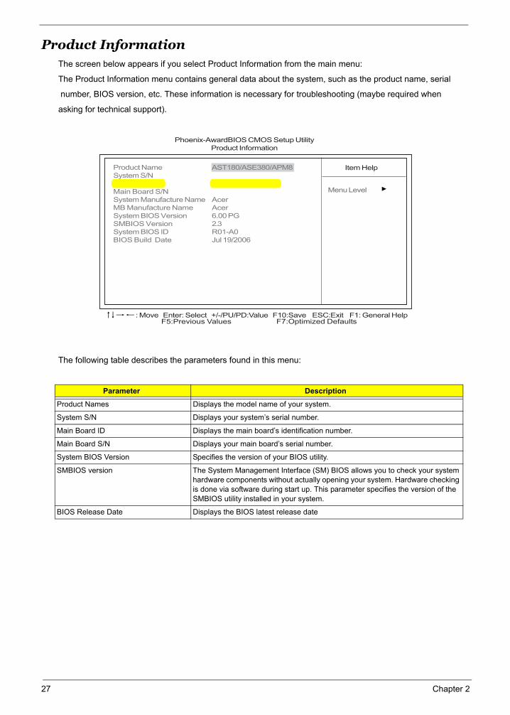
Product InformationThe screen below appears if you select Product Information from the main menu:
The Product Information menu contains general data about the system, such as the product name, serial
number, BIOS version, etc. These information is necessary for troubleshooting (maybe required when
asking for technical support).
The following table describes the parameters found in this menu:
Parameter Description
Product Names Displays the model name of your system.
System S/N Displays your system’s serial number.
Main Board ID Displays the main board’s identification number.
Main Board S/N Displays your main board’s serial number.
System BIOS Version Specifies the version of your BIOS utility.
SMBIOS version The System Management Interface (SM) BIOS allows you to check your system hardware components without actually opening your system. Hardware checking is done via software during start up. This parameter specifies the version of the SMBIOS utility installed in your system.
BIOS Release Date Displays the BIOS latest release date
Phoenix-AwardBIOS CMOS Setup UtilityProduct Information
Product Name AST180/ASE380/APM8System S/NMain Board ID EM61SM/EM61PMMain Board S/NSystem Manufacture Name AcerMB Manufacture Name AcerSystem BIOS Version 6.00 PGSMBIOS Version 2.3System BIOS ID R01-A0BIOS Build Date Jul 19/2006
Item Help
Menu Level
F5:Previous Values F7:Optimized Defaults: Move Enter: Select +/-/PU/PD:Value F10:Save ESC:Exit F1: General Help
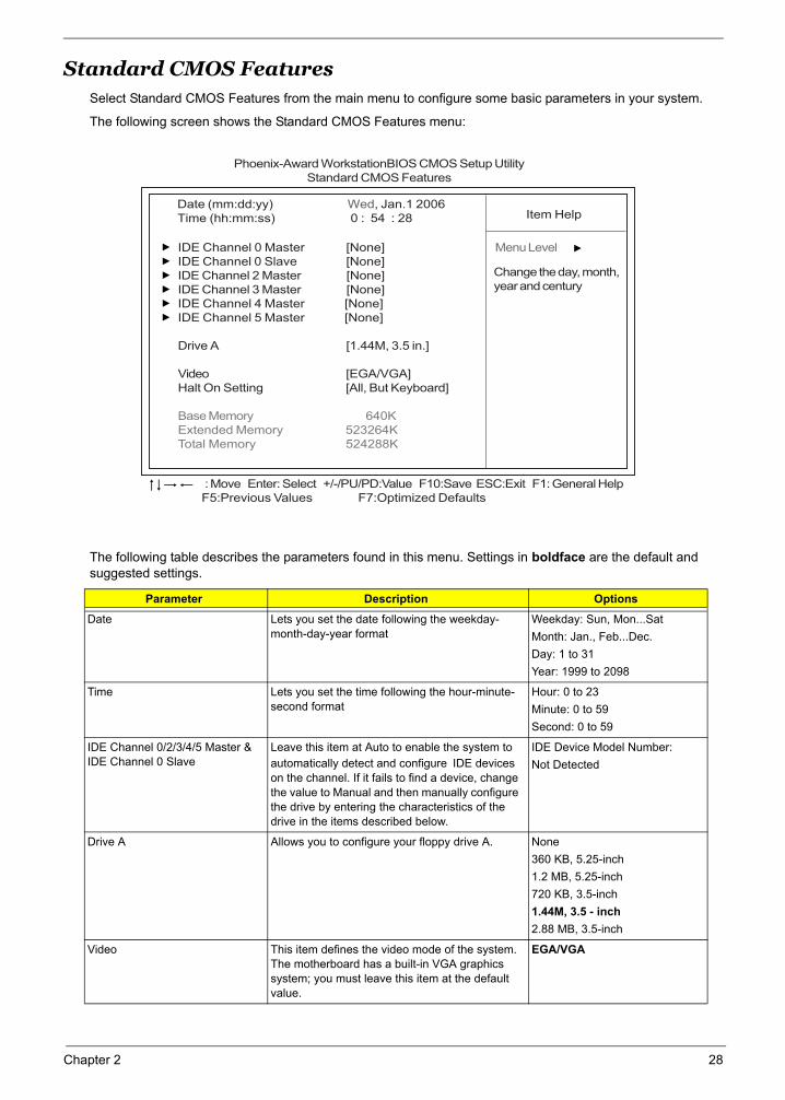
Standard CMOS FeaturesSelect Standard CMOS Features from the main menu to configure some basic parameters in your system.
The following screen shows the Standard CMOS Features menu:
The following table describes the parameters found in this menu. Settings in boldface are the default and suggested settings.
Parameter Description Options
Date Lets you set the date following the weekday-month-day-year format
Weekday: Sun, Mon...SatMonth: Jan., Feb...Dec.Day: 1 to 31Year: 1999 to 2098
Time Lets you set the time following the hour-minute-second format
Hour: 0 to 23Minute: 0 to 59Second: 0 to 59
IDE Channel 0/2/3/4/5 Master & IDE Channel 0 Slave
Leave this item at Auto to enable the system to automatically detect and configure IDE devices on the channel. If it fails to find a device, change the value to Manual and then manually configure the drive by entering the characteristics of the drive in the items described below.
IDE Device Model Number: Not Detected
Drive A Allows you to configure your floppy drive A. None360 KB, 5.25-inch1.2 MB, 5.25-inch720 KB, 3.5-inch1.44M, 3.5 - inch2.88 MB, 3.5-inch
Video This item defines the video mode of the system. The motherboard has a built-in VGA graphics system; you must leave this item at the default value.
EGA/VGA
Phoenix-Award WorkstationBIOS CMOS Setup UtilityStandard CMOS Features
Date (mm:dd:yy) Wed, Jan.1 2006Time (hh:mm:ss) 0 : 54 : 28 Item Help
Menu Level
Change the day, month,year and century
F5:Previous Values F7:Optimized Defaults: Move Enter: Select +/-/PU/PD:Value F10:Save ESC:Exit F1: General Help
IDE Channel 0 Master [None]IDE Channel 0 Slave [None]IDE Channel 2 Master [None]IDE Channel 3 Master [None]IDE Channel 4 Master [None]IDE Channel 5 Master [None]
Drive A [1.44M, 3.5 in.]
Video [EGA/VGA]Halt On Setting [All, But Keyboard]
Base Memory 640KExtended Memory 523264KTotal Memory 524288K
Chapter 2 28
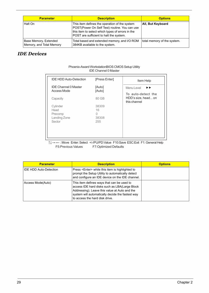
IDE Devices
Halt On This item defines the operation of the system POST(Power On Self Test) routine. You can use this item to select which types of errors in the POST are sufficient to halt the system.
All, But Keyboard
Base Memory, Extended Memory, and Total Memory
Total based and extended memory, and I/O ROM 384KB available to the system.
total memory of the system.
Parameter Description Options
IDE HDD Auto-Detection Press <Enter> while this item is highlighted to prompt the Setup Utility to automatically detect and configure an IDE device on the IDE channel.
Access Mode(Auto) This item defines ways that can be used to access IDE hard disks such as LBA(Large Block Addressing). Leave this value at Auto and the system will automatically decide the fastest way to access the hard disk drive.
Parameter Description Options
Phoenix-Award WorkstationBIOS CMOS Setup UtilityIDE Channel 0 Master
F5:Previous Values F7:Optimized Defaults
: Move Enter: Select +/-/PU/PD:Value F10:Save ESC:Exit F1: General Help
IDE HDD Auto-Detection [Press Enter]
IDE Channel 0 Master [Auto]Access Mode [Auto]
Capacity 80 GB
Cylinder 38309Head 16Precomp 0Landing Zone 38308Sector 255
Item Help
Menu Level
To auto-detect theHDD’s size, head... onthis channel
29 Chapter 2
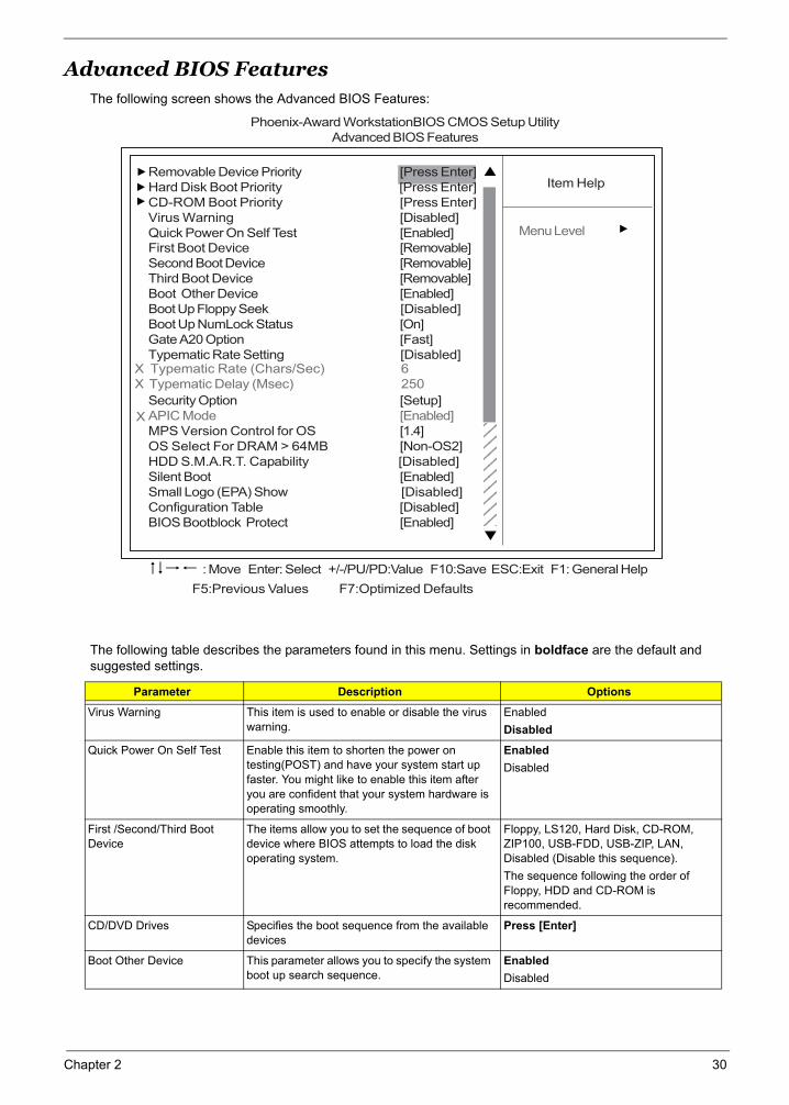
Advanced BIOS FeaturesThe following screen shows the Advanced BIOS Features:
The following table describes the parameters found in this menu. Settings in boldface are the default and suggested settings.
Parameter Description Options
Virus Warning This item is used to enable or disable the virus warning.
EnabledDisabled
Quick Power On Self Test Enable this item to shorten the power on testing(POST) and have your system start up faster. You might like to enable this item after you are confident that your system hardware is operating smoothly.
EnabledDisabled
First /Second/Third Boot Device
The items allow you to set the sequence of boot device where BIOS attempts to load the disk operating system.
Floppy, LS120, Hard Disk, CD-ROM, ZIP100, USB-FDD, USB-ZIP, LAN, Disabled (Disable this sequence).The sequence following the order of Floppy, HDD and CD-ROM is recommended.
CD/DVD Drives Specifies the boot sequence from the available devices
Press [Enter]
Boot Other Device This parameter allows you to specify the system boot up search sequence.
EnabledDisabled
Phoenix-Award WorkstationBIOS CMOS Setup UtilityAdvanced BIOS Features
Item Help
Menu Level
: Move Enter: Select +/-/PU/PD:Value F10:Save ESC:Exit F1: General Help
Removable Device Priority [Press Enter]Hard Disk Boot Priority [Press Enter]CD-ROM Boot Priority [Press Enter]Virus Warning [Disabled]Quick Power On Self Test [Enabled]First Boot Device [Removable]Second Boot Device [Removable]Third Boot Device [Removable]Boot Other Device [Enabled]Boot Up Floppy Seek [Disabled]Boot Up NumLock Status [On]Gate A20 Option [Fast]Typematic Rate Setting [Disabled]
Security Option [Setup]APIC Mode [Enabled]MPS Version Control for OS [1.4]OS Select For DRAM > 64MB [Non-OS2]HDD S.M.A.R.T. Capability [Disabled]Silent Boot [Enabled]Small Logo (EPA) Show [Disabled]Configuration Table [Disabled]BIOS Bootblock Protect [Enabled]
12121212121212121212
X Typematic Rate (Chars/Sec) 6X Typematic Delay (Msec) 250
F5:Previous Values F7:Optimized Defaults
X
Chapter 2 30
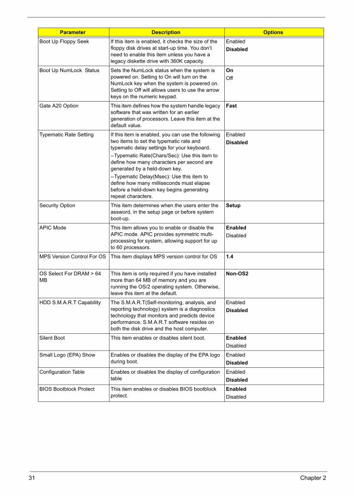
Boot Up Floppy Seek If this item is enabled, it checks the size of the floppy disk drives at start-up time. You don’t need to enable this item unless you have a legacy diskette drive with 360K capacity.
EnabledDisabled
Boot Up NumLock Status Sets the NumLock status when the system is powered on. Setting to On will turn on the NumLock key when the system is powered on. Setting to Off will allows users to use the arrow keys on the numeric keypad.
OnOff
Gate A20 Option This item defines how the system handle legacy software that was written for an earlier generation of processors. Leave this item at the default value.
Fast
Typematic Rate Setting If this item is enabled, you can use the following two items to set the typematic rate and typematic delay settings for your keyboard.--Typematic Rate(Chars/Sec): Use this item to define how many characters per second are generated by a held-down key.--Typematic Delay(Msec): Use this item to define how many milliseconds must elapse before a held-down key begins generating repeat characters.
Enabled Disabled
Security Option This item determines when the users enter the assword, in the setup page or before system boot-up.
Setup
APIC Mode This item allows you to enable or disable the APIC mode. APIC provides symmetric multi-processing for system, allowing support for up to 60 processors.
Enabled Disabled
MPS Version Control For OS This item displays MPS version control for OS 1.4
OS Select For DRAM > 64 MB
This item is only required if you have installed more than 64 MB of memory and you are running the OS/2 operating system. Otherwise, leave this item at the default.
Non-OS2
HDD S.M.A.R.T Capability The S.M.A.R.T(Self-monitoring, analysis, and reporting technology) system is a diagnostics technology that monitors and predicts device performance. S.M.A.R.T software resides on both the disk drive and the host computer.
EnabledDisabled
Silent Boot This item enables or disables silent boot. EnabledDisabled
Small Logo (EPA) Show Enables or disables the display of the EPA logo during boot.
EnabledDisabled
Configuration Table Enables or disables the display of configuration table
EnabledDisabled
BIOS Bootblock Protect This item enables or disables BIOS bootblock protect.
EnabledDisabled
Parameter Description Options
31 Chapter 2
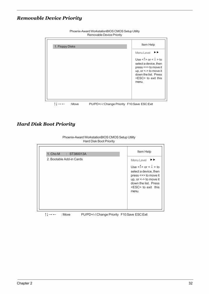
Removable Device Priority
Hard Disk Boot Priority
Phoenix-Award WorkstationBIOS CMOS Setup UtilityRemovable Device Priority
Item Help
Menu Level
: Move PU/PD+/-/:Change Priority F10:Save ESC:Exit
1. Floppy Disks
Use < > or < > to
select a device, thenpress <+> to move itup, or <-> to move itdown the list. Press<ESC> to exit thismenu.
Phoenix-Award WorkstationBIOS CMOS Setup UtilityHard Disk Boot Priority
2. Bootable Add-in Cards
Item Help
Menu Level
: Move PU/PD+/-/:Change Priority F10:Save ESC:Exit
1. Cho M : ST380013A
Use < > or < > to
select a device, thenpress <+> to move itup, or <-> to move itdown the list. Press<ESC> to exit thismenu.
Chapter 2 32
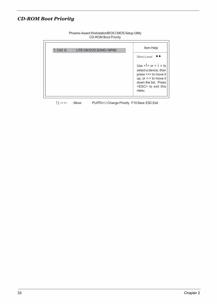
CD-ROM Boot Priority
Phoenix-Award WorkstationBIOS CMOS Setup UtilityCD-ROM Boot Priority
Item Help
Menu Level
Use < > or < > to
select a device, thenpress <+> to move itup, or <-> to move itdown the list. Press<ESC> to exit thismenu.
1. Ch0 S. : LITE-ON DVD SOHD-16P9S
: Move PU/PD+/-/:Change Priority F10:Save ESC:Exit
33 Chapter 2
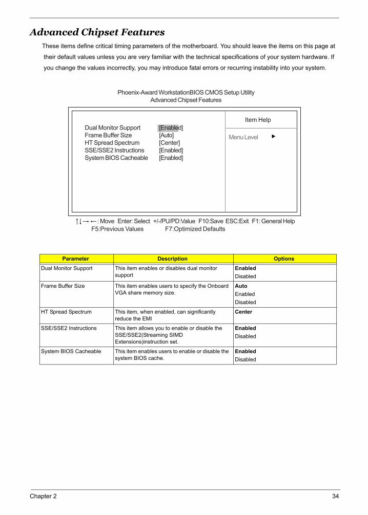
Advanced Chipset FeaturesThese items define critical timing parameters of the motherboard. You should leave the items on this page at
their default values unless you are very familiar with the technical specifications of your system hardware. If
you change the values incorrectly, you may introduce fatal errors or recurring instability into your system.
Parameter Description Options
Dual Monitor Support This item enables or disables dual monitor support
EnabledDisabled
Frame Buffer Size This item enables users to specify the Onboard VGA share memory size.
AutoEnabledDisabled
HT Spread Spectrum This item, when enabled, can significantly reduce the EMI
Center
SSE/SSE2 Instructions This item allows you to enable or disable the SSE/SSE2(Streaming SIMD Extensions)instruction set.
EnabledDisabled
System BIOS Cacheable This item enables users to enable or disable the system BIOS cache.
EnabledDisabled
Phoenix-Award WorkstationBIOS CMOS Setup UtilityAdvanced Chipset Features
Item Help
Menu Level
F5:Previous Values F7:Optimized Defaults
: Move Enter: Select +/-/PU/PD:Value F10:Save ESC:Exit F1: General Help
Dual Monitor Support [Enabled]Frame Buffer Size [Auto]HT Spread Spectrum [Center]SSE/SSE2 Instructions [Enabled]System BIOS Cacheable [Enabled]
Chapter 2 34
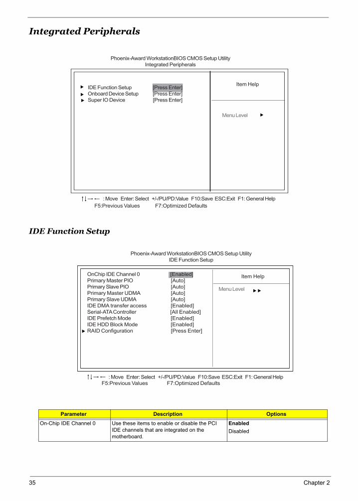
Integrated Peripherals
IDE Function Setup
Parameter Description Options
On-Chip IDE Channel 0 Use these items to enable or disable the PCI IDE channels that are integrated on the motherboard.
EnabledDisabled
Phoenix-Award WorkstationBIOS CMOS Setup UtilityIntegrated Peripherals
: Move Enter: Select +/-/PU/PD:Value F10:Save ESC:Exit F1: General Help
F5:Previous Values F7:Optimized Defaults
Item Help
Menu Level
IDE Function Setup [Press Enter]Onboard Device Setup [Press Enter]Super IO Device [Press Enter]
F5:Previous Values F7:Optimized Defaults: Move Enter: Select +/-/PU/PD:Value F10:Save ESC:Exit F1: General Help
Item Help
Menu Level
Phoenix-Award WorkstationBIOS CMOS Setup UtilityIDE Function Setup
OnChip IDE Channel 0 [Enabled]Primary Master PIO [Auto]Primary Slave PIO [Auto]Primary Master UDMA [Auto]Primary Slave UDMA [Auto]IDE DMA transfer access [Enabled]Serial-ATA Controller [All Enabled]IDE Prefetch Mode [Enabled]IDE HDD Block Mode [Enabled]RAID Configuration [Press Enter]
35 Chapter 2
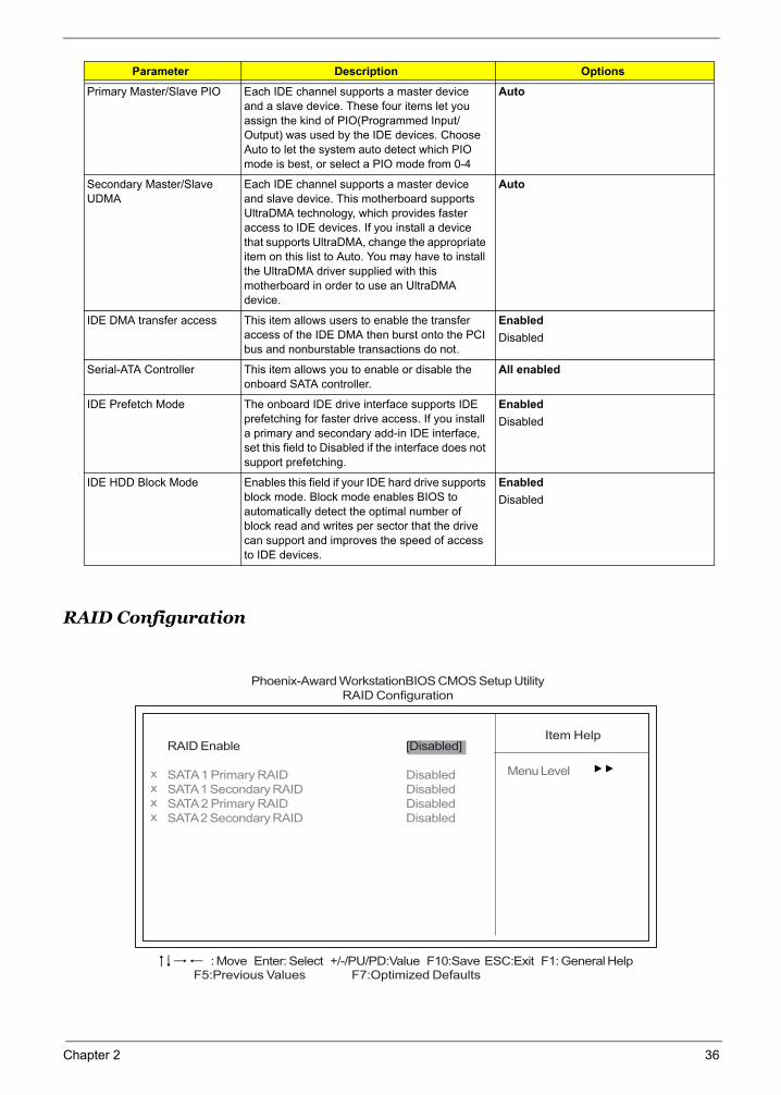
RAID Configuration
Primary Master/Slave PIO Each IDE channel supports a master device and a slave device. These four items let you assign the kind of PIO(Programmed Input/Output) was used by the IDE devices. Choose Auto to let the system auto detect which PIO mode is best, or select a PIO mode from 0-4
Auto
Secondary Master/Slave UDMA
Each IDE channel supports a master device and slave device. This motherboard supports UltraDMA technology, which provides faster access to IDE devices. If you install a device that supports UltraDMA, change the appropriate item on this list to Auto. You may have to install the UltraDMA driver supplied with this motherboard in order to use an UltraDMA device.
Auto
IDE DMA transfer access This item allows users to enable the transfer access of the IDE DMA then burst onto the PCI bus and nonburstable transactions do not.
EnabledDisabled
Serial-ATA Controller This item allows you to enable or disable the onboard SATA controller.
All enabled
IDE Prefetch Mode The onboard IDE drive interface supports IDE prefetching for faster drive access. If you install a primary and secondary add-in IDE interface, set this field to Disabled if the interface does not support prefetching.
EnabledDisabled
IDE HDD Block Mode Enables this field if your IDE hard drive supports block mode. Block mode enables BIOS to automatically detect the optimal number of block read and writes per sector that the drive can support and improves the speed of access to IDE devices.
EnabledDisabled
Parameter Description Options
F5:Previous Values F7:Optimized Defaults: Move Enter: Select +/-/PU/PD:Value F10:Save ESC:Exit F1: General Help
Item Help
Menu Level
RAID Enable [Disabled]
SATA 1 Primary RAID DisabledSATA 1 Secondary RAID DisabledSATA 2 Primary RAID DisabledSATA 2 Secondary RAID Disabled
xxxx
Phoenix-Award WorkstationBIOS CMOS Setup UtilityRAID Configuration
Chapter 2 36
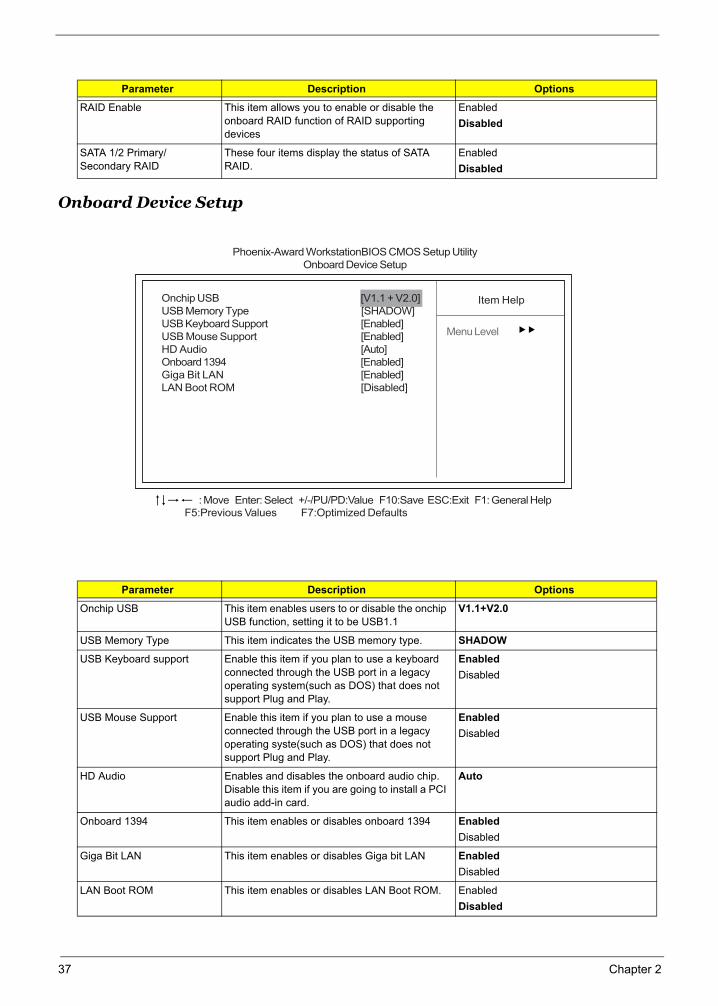
Onboard Device Setup
Parameter Description Options
RAID Enable This item allows you to enable or disable the onboard RAID function of RAID supporting devices
EnabledDisabled
SATA 1/2 Primary/Secondary RAID
These four items display the status of SATA RAID.
EnabledDisabled
Parameter Description Options
Onchip USB This item enables users to or disable the onchip USB function, setting it to be USB1.1
V1.1+V2.0
USB Memory Type This item indicates the USB memory type. SHADOW
USB Keyboard support Enable this item if you plan to use a keyboard connected through the USB port in a legacy operating system(such as DOS) that does not support Plug and Play.
EnabledDisabled
USB Mouse Support Enable this item if you plan to use a mouse connected through the USB port in a legacy operating syste(such as DOS) that does not support Plug and Play.
EnabledDisabled
HD Audio Enables and disables the onboard audio chip. Disable this item if you are going to install a PCI audio add-in card.
Auto
Onboard 1394 This item enables or disables onboard 1394 EnabledDisabled
Giga Bit LAN This item enables or disables Giga bit LAN EnabledDisabled
LAN Boot ROM This item enables or disables LAN Boot ROM. EnabledDisabled
F5:Previous Values F7:Optimized Defaults: Move Enter: Select +/-/PU/PD:Value F10:Save ESC:Exit F1: General Help
Item Help
Menu Level
Onchip USB [V1.1 + V2.0]USB Memory Type [SHADOW]USB Keyboard Support [Enabled]USB Mouse Support [Enabled]HD Audio [Auto]Onboard 1394 [Enabled]Giga Bit LAN [Enabled]LAN Boot ROM [Disabled]
Phoenix-Award WorkstationBIOS CMOS Setup UtilityOnboard Device Setup
37 Chapter 2
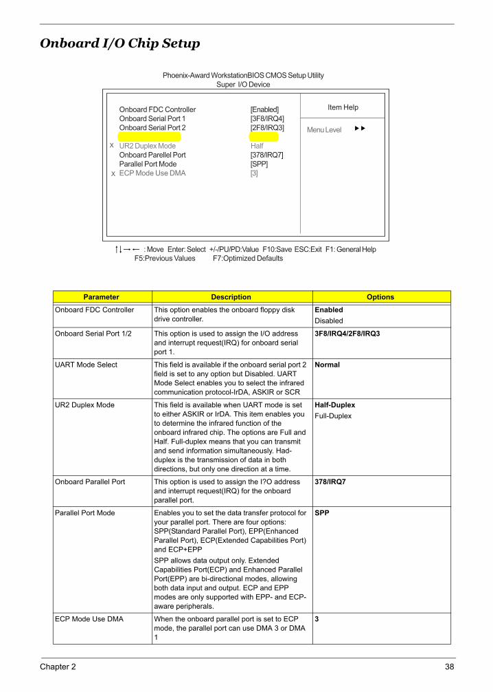
Onboard I/O Chip Setup
Parameter Description Options
Onboard FDC Controller This option enables the onboard floppy disk drive controller.
EnabledDisabled
Onboard Serial Port 1/2 This option is used to assign the I/O address and interrupt request(IRQ) for onboard serial port 1.
3F8/IRQ4/2F8/IRQ3
UART Mode Select This field is available if the onboard serial port 2 field is set to any option but Disabled. UART Mode Select enables you to select the infrared communication protocol-IrDA, ASKIR or SCR
Normal
UR2 Duplex Mode This field is available when UART mode is set to either ASKIR or IrDA. This item enables you to determine the infrared function of the onboard infrared chip. The options are Full and Half. Full-duplex means that you can transmit and send information simultaneously. Had-duplex is the transmission of data in both directions, but only one direction at a time.
Half-DuplexFull-Duplex
Onboard Parallel Port This option is used to assign the I?O address and interrupt request(IRQ) for the onboard parallel port.
378/IRQ7
Parallel Port Mode Enables you to set the data transfer protocol for your parallel port. There are four options: SPP(Standard Parallel Port), EPP(Enhanced Parallel Port), ECP(Extended Capabilities Port) and ECP+EPPSPP allows data output only. Extended Capabilities Port(ECP) and Enhanced Parallel Port(EPP) are bi-directional modes, allowing both data input and output. ECP and EPP modes are only supported with EPP- and ECP-aware peripherals.
SPP
ECP Mode Use DMA When the onboard parallel port is set to ECP mode, the parallel port can use DMA 3 or DMA 1
3
F5:Previous Values F7:Optimized Defaults
Phoenix-Award WorkstationBIOS CMOS Setup UtilitySuper I/O Device
: Move Enter: Select +/-/PU/PD:Value F10:Save ESC:Exit F1: General Help
Item Help
Menu Level
Onboard FDC Controller [Enabled]Onboard Serial Port 1 [3F8/IRQ4]Onboard Serial Port 2 [2F8/IRQ3]UART Mode Select [Normal]UR2 Duplex Mode HalfOnboard Parellel Port [378/IRQ7]Parallel Port Mode [SPP]ECP Mode Use DMA [3]
X
X
Chapter 2 38
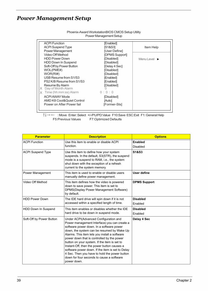
Power Management Setup
Parameter Description Options
ACPI Function Use this item to enable or disable ACPI function.
EnabledDisabled
ACPI Suspend Type Use this item to define how your system suspends. In the default, S3(STR), the suspend mode is a suspend to RAM, i.e., the system shut down with the exception of a refresh current to the system memory.
S1&S3
Power Management This item is used to enable or disable users manually define power management.
User define
Video Off Method This item defines how the video is powered down to save power. This item is set to DPMS(Display Power Management Software) by default.
DPMS Support
HDD Power Down The IDE hard drive will spin down if it is not accessed within a specified length of time.
DisabledEnabled
HDD Down In Suspend This item enables or disables whether the IDE hard drive to be down in suspend mode.
DisabledEnabled
Soft-Off by Power Button Under ACPI(Advanced Configuration and Power management Interface) you can create a software power down. In a software power down, the system can be resumed by Wake Up Alarms. This item lets you install a software power down that is controlled by the power button on your system. If the item is set to Instant-Off, then the power button causes a software power down. If the item is set to Delay 4 Sec. Then you have to hold the power button down for four seconds to cause a software power down.
Delay 4 Sec
Phoenix-Award WorkstationBIOS CMOS Setup UtilityPower Management Setup
Item Help
Menu Level
F5:Previous Values F7:Optimized Defaults
: Move Enter: Select +/-/PU/PD:Value F10:Save ESC:Exit F1: General Help
ACPI Function [Enabled]ACPI Suspend Type [S1&S3]Power Management [User Define]Video Off Method [DPMS Support]HDD Power Down [Disabled]HDD Down In Suspend [Disabled]Soft-Off by Power Button [Delay 4 Sec]WOL(PME#) [Disabled]WOR(RI#) [Disabled]USB Resume from S1/S3 [Enabled]PS2 K/B Resume from S1/S3 [Enabled]Resume By Alarm [Disabled]
ACPI AWAY Mode [Disabled]AMD K8 Cool&Quiet Control [Auto]Power on After Power fail [Former-Sts]
X
X Day of Month Alarm 0 Time (hh:mm:ss) Alarm 0 : 0 : 0
39 Chapter 2
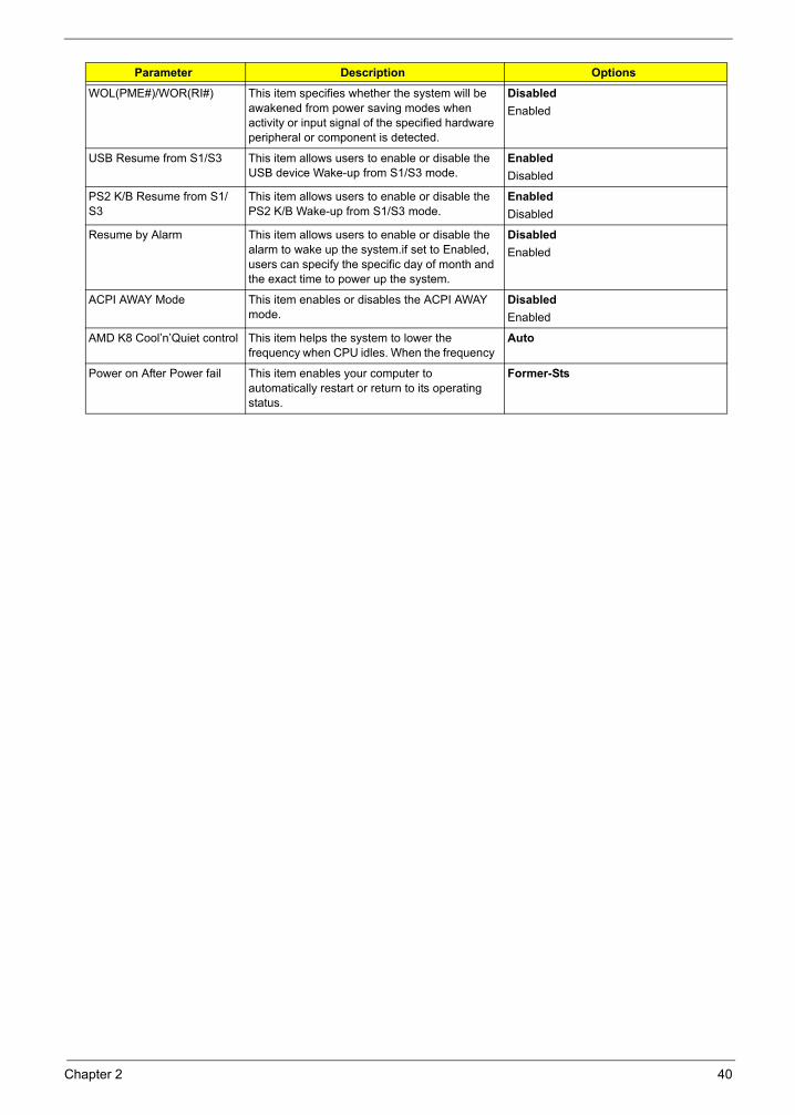
WOL(PME#)/WOR(RI#) This item specifies whether the system will be awakened from power saving modes when activity or input signal of the specified hardware peripheral or component is detected.
DisabledEnabled
USB Resume from S1/S3 This item allows users to enable or disable the USB device Wake-up from S1/S3 mode.
EnabledDisabled
PS2 K/B Resume from S1/S3
This item allows users to enable or disable the PS2 K/B Wake-up from S1/S3 mode.
EnabledDisabled
Resume by Alarm This item allows users to enable or disable the alarm to wake up the system.if set to Enabled, users can specify the specific day of month and the exact time to power up the system.
DisabledEnabled
ACPI AWAY Mode This item enables or disables the ACPI AWAY mode.
DisabledEnabled
AMD K8 Cool’n’Quiet control This item helps the system to lower the frequency when CPU idles. When the frequency
Auto
Power on After Power fail This item enables your computer to automatically restart or return to its operating status.
Former-Sts
Parameter Description Options
Chapter 2 40
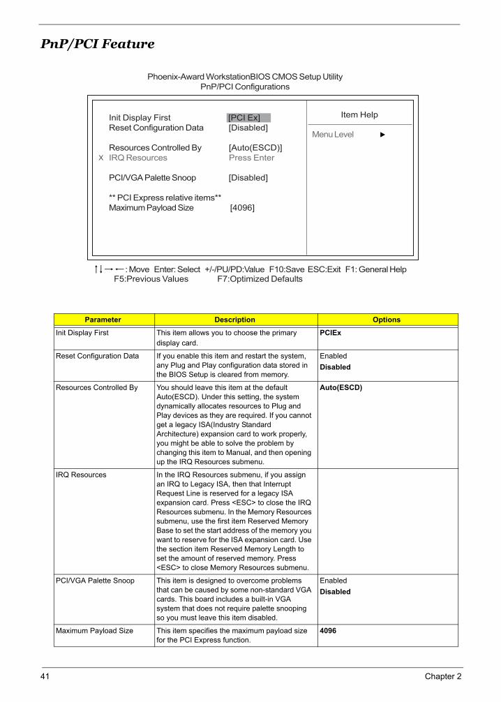
PnP/PCI Feature
Parameter Description Options
Init Display First This item allows you to choose the primary display card.
PCIEx
Reset Configuration Data If you enable this item and restart the system, any Plug and Play configuration data stored in the BIOS Setup is cleared from memory.
EnabledDisabled
Resources Controlled By You should leave this item at the default Auto(ESCD). Under this setting, the system dynamically allocates resources to Plug and Play devices as they are required. If you cannot get a legacy ISA(Industry Standard Architecture) expansion card to work properly, you might be able to solve the problem by changing this item to Manual, and then opening up the IRQ Resources submenu.
Auto(ESCD)
IRQ Resources In the IRQ Resources submenu, if you assign an IRQ to Legacy ISA, then that Interrupt Request Line is reserved for a legacy ISA expansion card. Press <ESC> to close the IRQ Resources submenu. In the Memory Resources submenu, use the first item Reserved Memory Base to set the start address of the memory you want to reserve for the ISA expansion card. Use the section item Reserved Memory Length to set the amount of reserved memory. Press <ESC> to close Memory Resources submenu.
PCI/VGA Palette Snoop This item is designed to overcome problems that can be caused by some non-standard VGA cards. This board includes a built-in VGA system that does not require palette snooping so you must leave this item disabled.
EnabledDisabled
Maximum Payload Size This item specifies the maximum payload size for the PCI Express function.
4096
Phoenix-Award WorkstationBIOS CMOS Setup UtilityPnP/PCI Configurations
Init Display First [PCI Ex]Reset Configuration Data [Disabled]
Resources Controlled By [Auto(ESCD)]IRQ Resources Press Enter
PCI/VGA Palette Snoop [Disabled]
** PCI Express relative items**Maximum Payload Size [4096]
Item Help
Menu Level
X
F5:Previous Values F7:Optimized Defaults: Move Enter: Select +/-/PU/PD:Value F10:Save ESC:Exit F1: General Help
41 Chapter 2
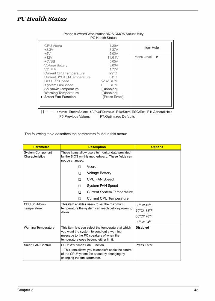
PC Health Status
The following table describes the parameters found in this menu:
Parameter Description Options
System Component Characteristics
These items allow users to monitor data provided by the BIOS on this motherboard. These fields can not be changed.
Vcore
Voltage Battery
CPU FAN Speed
System FAN Speed
Current System Temperature
Current CPU TemperatureCPU Shutdown Temperature
This item enables users to set the maximum temperature the system can reach before powering down.
60oC/140oF
70oC/158oF
80oC/176oF
90oC/194oF
Warning Temperature This item lets you select the temperature at which you want the system to send out a warning message to the PC speakers of when the temperature goes beyond either limit.
Disabled
Smart FAN Control SPU/SYS Smart Fan Function-- This item allows you to enable/disable the control of the CPU/system fan speed by changing by changing the fan parameter.
Press Enter
Phoenix-Award WorkstationBIOS CMOS Setup UtilityPC Health Status
Item Help
Menu Level
F5:Previous Values F7:Optimized Defaults
: Move Enter: Select +/-/PU/PD:Value F10:Save ESC:Exit F1: General Help
CPU Vcore 1.29V+3.3V 3.37V+5V 5.00V+12V 11.61V+5VSB 5.05VVoltage Battery 3.00VVDIMM 1.77VCurrent CPU Temperature 29°CCurrent SYSTEMTemperature 31°CCPU Fan Speed 5232 RPM System Fan Speed 0 RPMShutdown Temperature [Disabled]Warning Temperature [Disabled]Smart Fan Function [Press Enter]
Chapter 2 42
Set Supervisor/User PasswordWhen this function is selected, the following message appears at the center of the screen to assist you in creating a password.
ENTER PASSWORDType the password, up to eight characters, and press<Enter>. The password typed now will clear any previously entered password from CMOS memory. You will be asked to confirm the password. Type the password again and press ,Enter>. You may also press <Esc> to abort the selection.
To disable password, just press <Enter> when you are prompted to enter password. A message will confirm the password being disabled. Once the password is disabled, the system will boot and you can enter BIOS Setup freely.
PASSWORD DISABLEDIf you have selected “System” in “Security Option” of “BIOS Features Setup” menu, you will be prompted for the password every time the system reboots or any time you try to enter BIOS Setup.
If you have selected “Setup” at “Security Option” from “BIOS Features Setup” menu, you will be prompted for the password only when you enter BIOS Setup.
Supervisor Password has higher priority than User Password. You can use Supervisor Password when booting the system or entering BIOS Setup to modify all settings. Also you system or entering BIOS Setup but can not modify any setting if Supervisor Password is enabled.
43 Chapter 2
Load Default SettingsSelecting the field loads the factory defaults for BIOS and Chipset Features which the system automatically. detects. THis option opens a dialog box that lets you install optimized defaults for all appropriate items in the Setup Utility. Press <OK> and then <Enter> to install the defaults. Press <Cancel> and then <Enter> to not install the defaults.
If you only want to install setup defaults for a specific option, select and display that option, and then press<F9>.
Chapter 2 44

Save & Exit Setup
Highlight this item and press <Enter> to save the changes that you have made in the Setup Utility and exit the Setup Utility.
When the Save and Exit dialog box appears, press <Y> to save and exit, or press <N> to return to the main menu.
45 Chapter 2

Exit Without SavingHighlight this item and press <Enter> to discard any changes that you have made in the Setup Utility and exit the Setup Utility.
When the Exit Without Saving dialog box appears, press <Y> to discard changes and exit, or press <N> to return to the main menu.
NOTE: If you have made settings that you do not want to save, use the "Exit Without Saving" item and press <Y> to discard any changes you have made.
Chapter 2 46
Machine Disassembly and Replacement
Chapter 3
To disassemble the computer, you need the following tools:
Wrist grounding strap and conductive mat for preventing electrostatic discharge.
Wire cutter.
Phillips screwdriver (may require different size).
NOTE: The screws for the different components vary in size. During the disassembly process, group the screws with the corresponding components to avoid mismatches when putting back the components.
Chapter 3 47

General Information
Before You Begin
Before proceeding with the disassenbly procedure, make sure that you do the following:
1. Turn off the power to the system and all peripherals.
2. Unplug the AC adapter and all power and signal cables from the system.
48 Chapter 3

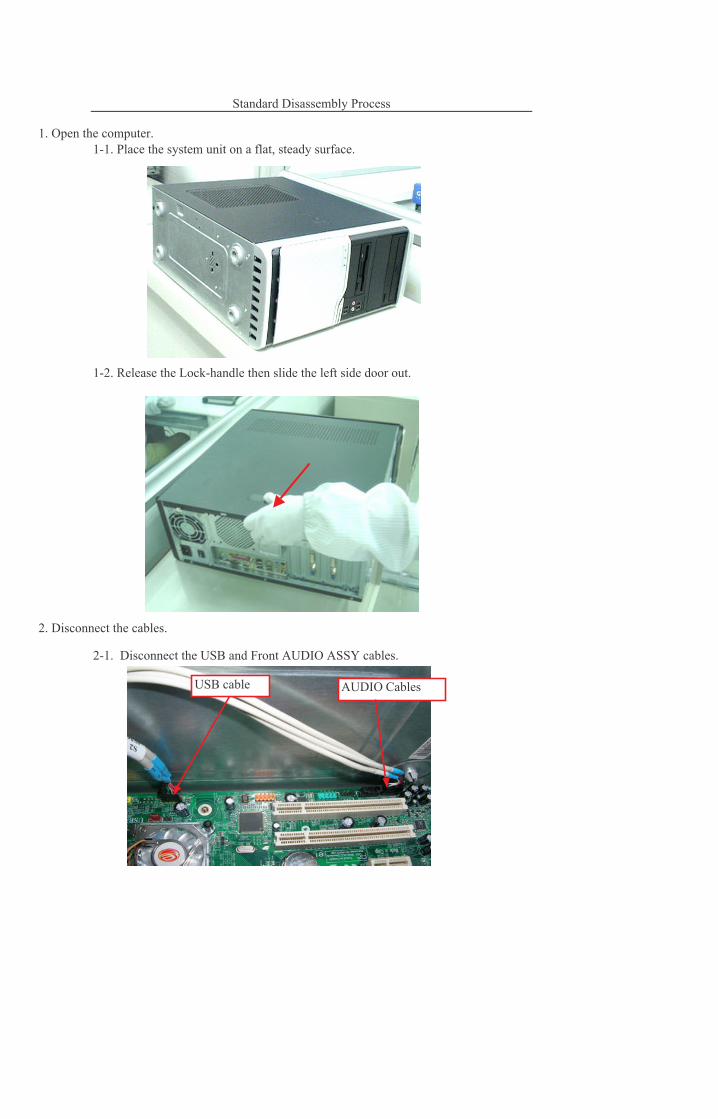
Disassembly ProcedureThis section tells you how to disassemble the system when you need to perform system service. Please also refer to the disassembly video, if available.
CAUTION: Before you proceed, make sure you have turned off the system and all peripherals connected to it.
Chapter 3 49
������������ � �������������� ������������������
� ������������������������
���������� ������ ������ ����� �� !�� �������� ���
����"��� ����"� ���
�����#������� ���$%�������� ���������� ����� ���������� �
��������� � ���������
������&�������������
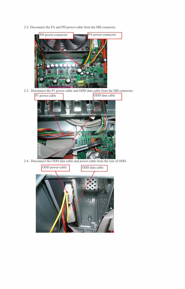
����������� � �������������"'�������� ��� ���(����� ��
��)��������� � ��������� �����������"'�������� ��� �������� �����
� ������������������������
��*��������� � ������"'������������������ ������� ��� ���(����� ��
���"'������ � ���"'������ �
���"'������� ������ ������
������ ����������"'�������
��+��������� � ���,����� �����������"'�������� ��� �������� �,�������(��
*����#���� ���,�����������'������'!� ���� �%�� ���,���� � ��� ����������
*���� ��� ���,�����������
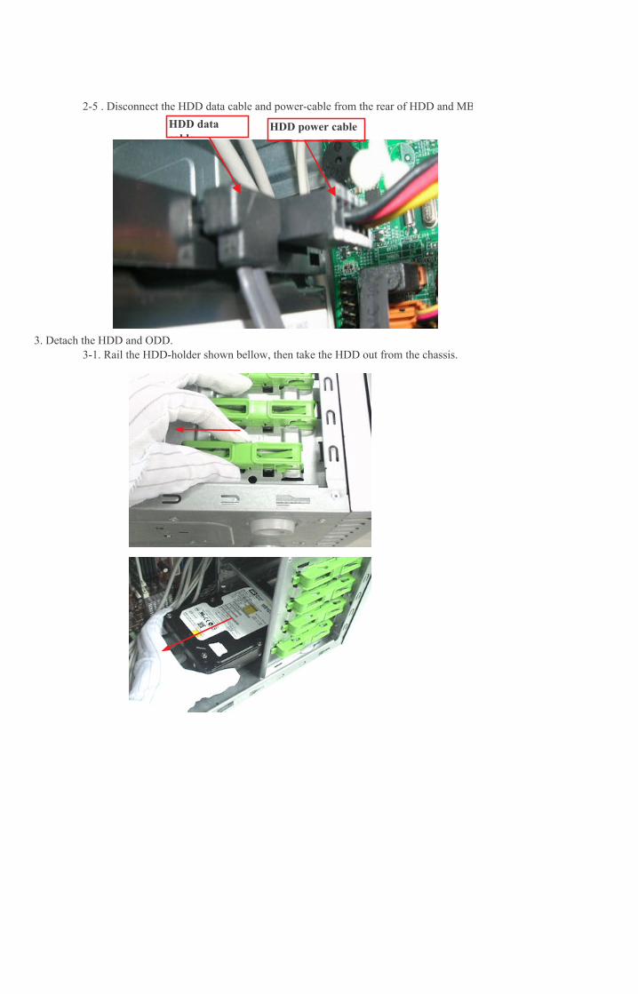
��������
��������� �����
*����#������� ��� ������� ������ ��� �� ���-��!� �������.�� ��� �� ���-���
*�*��#���� ���������������'������'!� ���� �%�� �������� � ��� ����������
#������� ������'���'������'!� ���� �%�� � ������������� /� ����'� �� ��
���0����������
)���� ��� �������(�����
+���������� � ���&���&����"'����������'������'�
+����#������� ���&���&����$� �� �������.��� �
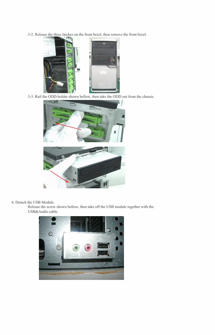
#������� ��� '��� ����'������'� �������.�� ���(�����
#������� ��� ������'����'������'� ���� �%�� � ��� ���
+���� ��� ���&���&����
1��#��.�� ���(�����
2��#��.�� ������ �������
&����$%����� �
� � ��
&����"'���
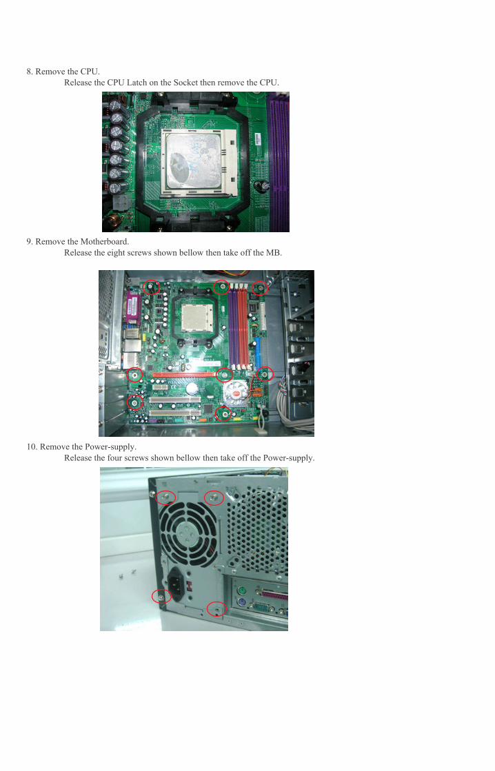
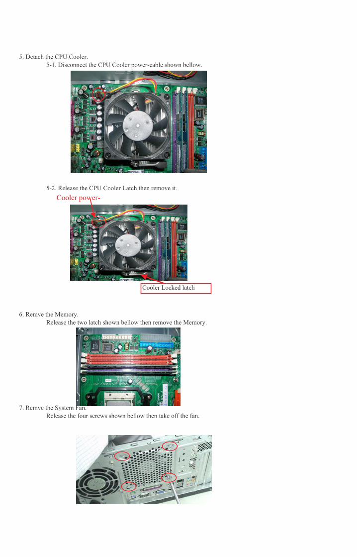
3��#��.�� ���&���
#������� ���&���$� ���� ����%� � �������.�� ���&���
#������� �����/� ����'����'������'� ���� �%�� � ���(��
#������� ��� ������'����'������'� ���� �%�� � ����'�����""���
4��#��.�� ���( ��������
�5��#��.�� ����'�����""���

Chapter 4
Troubleshooting
Please refer to generic troubleshooting guide for trougleshooting information relating to following topics:
Power-On Self-Test (POST)
POST Check Points
POST Error Messages List
Error Symptoms List
Chapter 4 69

70 Chapter 4
Jumper and Connector Information
Chapter 5
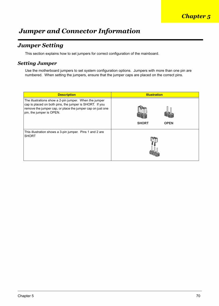
Jumper SettingThis section explains how to set jumpers for correct configuration of the mainboard.
Setting JumperUse the motherboard jumpers to set system configuration options. Jumpers with more than one pin are numbered. When setting the jumpers, ensure that the jumper caps are placed on the correct pins.
Description Illustration
The illustrations show a 2-pin jumper. When the jumper cap is placed on both pins, the jumper is SHORT. If you remove the jumper cap, or place the jumper cap on just one pin, the jumper is OPEN.
This illustration shows a 3-pin jumper. Pins 1 and 2 are SHORT
SHORT OPEN
Chapter 5 70
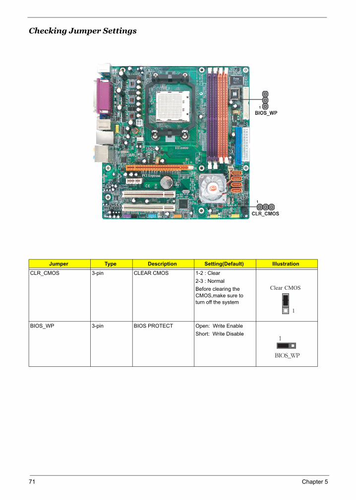
Checking Jumper Settings
Jumper Type Description Setting(Default) Illustration
CLR_CMOS 3-pin CLEAR CMOS 1-2 : Clear2-3 : NormalBefore clearing the CMOS,make sure to turn off the system
BIOS_WP 3-pin BIOS PROTECT Open: Write EnableShort: Write Disable
Clear CMOS
1
BIOS_WP
1
71 Chapter 5
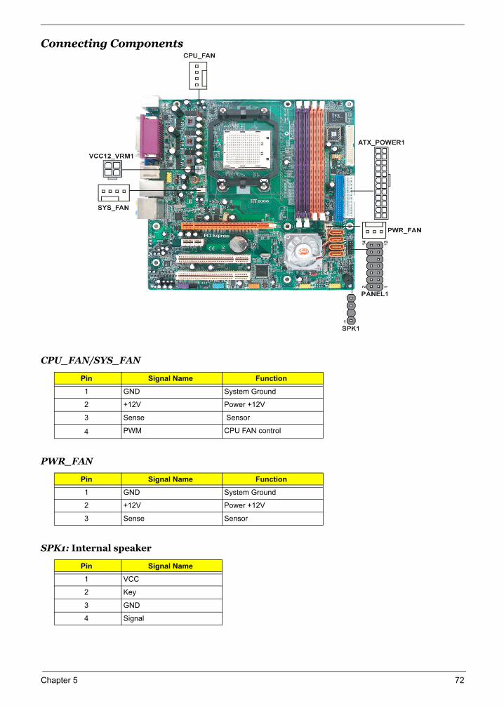
Connecting Components
CPU_FAN/SYS_FAN
Pin Signal Name Function
1 GND System Ground
2 +12V Power +12V
3 Sense Sensor
4 PWM CPU FAN control
PWR_FAN
Pin Signal Name Function
1 GND System Ground
2 +12V Power +12V
3 Sense Sensor
SPK1: Internal speaker
Pin Signal Name
1 VCC
2 Key
3 GND
4 Signal
Chapter 5 72
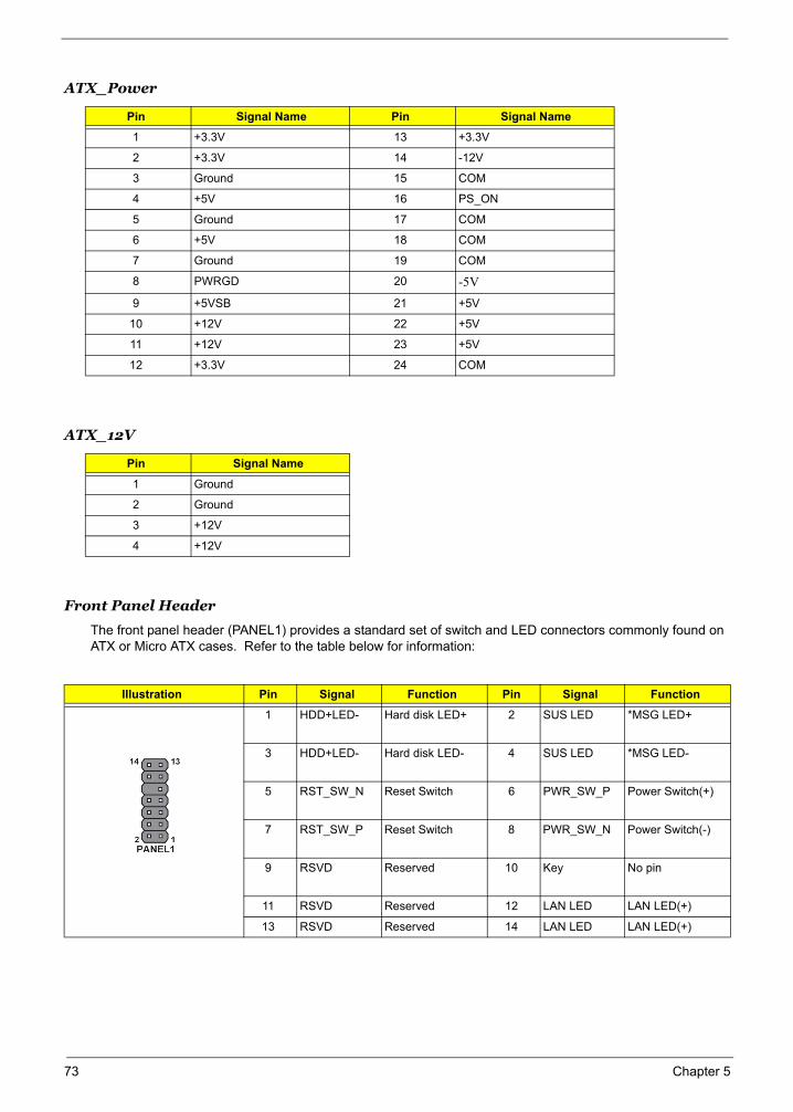
Front Panel Header
The front panel header (PANEL1) provides a standard set of switch and LED connectors commonly found on ATX or Micro ATX cases. Refer to the table below for information:
ATX_Power
Pin Signal Name Pin Signal Name
1 +3.3V 13 +3.3V
2 +3.3V 14 -12V
3 Ground 15 COM
4 +5V 16 PS_ON
5 Ground 17 COM
6 +5V 18 COM
7 Ground 19 COM
8 PWRGD 20 -5V9 +5VSB 21 +5V
10 +12V 22 +5V
11 +12V 23 +5V
12 +3.3V 24 COM
ATX_12V
Pin Signal Name
1 Ground
2 Ground
3 +12V
4 +12V
Illustration Pin Signal Function Pin Signal Function
1 HDD+LED- Hard disk LED+ 2 SUS LED *MSG LED+
3 HDD+LED- Hard disk LED- 4 SUS LED *MSG LED-
5 RST_SW_N Reset Switch 6 PWR_SW_P Power Switch(+)
7 RST_SW_P Reset Switch 8 PWR_SW_N Power Switch(-)
9 RSVD Reserved 10 Key No pin
11 RSVD Reserved 12 LAN LED LAN LED(+)
13 RSVD Reserved 14 LAN LED LAN LED(+)
73 Chapter 5
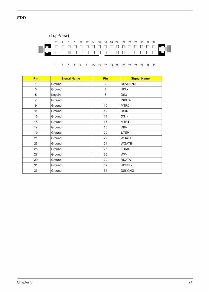
FDD
Pin Signal Name Pin Signal Name
1 Ground 2 DRVDEN0
3 Ground 4 HDL-
5 Keypin 6 DS3-
7 Ground 8 INDEX-
9 Ground 10 MTR0-
11 Ground 12 DS0-
13 Ground 14 DS1-
15 Ground 16 MTR1-
17 Ground 18 DIR-
19 Ground 20 STEP-
21 Ground 22 WDATA
23 Ground 24 WGATE-
25 Ground 26 TRK0-
27 Ground 28 WP-
29 Ground 30 RDATA
31 Ground 32 HDSEL-
33 Ground 34 DSKCHG-
(Top-View)
2 4 6 8 10 12 14 16 18 20 22 24 26 28 30 32 34
1 3 5 7 9 11 13 15 17 19 21 23 25 27 29 31 33
Chapter 5 74
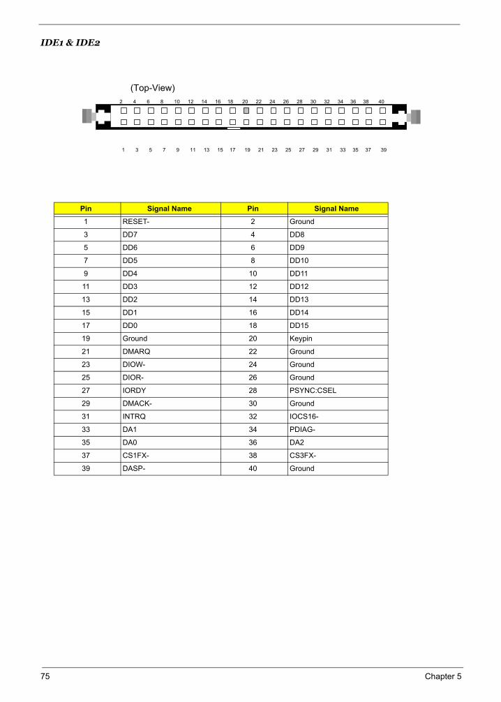
IDE1 & IDE2
Pin Signal Name Pin Signal Name
1 RESET- 2 Ground
3 DD7 4 DD8
5 DD6 6 DD9
7 DD5 8 DD10
9 DD4 10 DD11
11 DD3 12 DD12
13 DD2 14 DD13
15 DD1 16 DD14
17 DD0 18 DD15
19 Ground 20 Keypin
21 DMARQ 22 Ground
23 DIOW- 24 Ground
25 DIOR- 26 Ground
27 IORDY 28 PSYNC:CSEL
29 DMACK- 30 Ground
31 INTRQ 32 IOCS16-
33 DA1 34 PDIAG-
35 DA0 36 DA2
37 CS1FX- 38 CS3FX-
39 DASP- 40 Ground
(Top-View)
2 4 6 8 10 12 14 16 18 20 22 24 26 28 30 32 34 36 38 40
1 3 5 7 9 11 13 15 17 19 21 23 25 27 29 31 33 35 37 39
75 Chapter 5
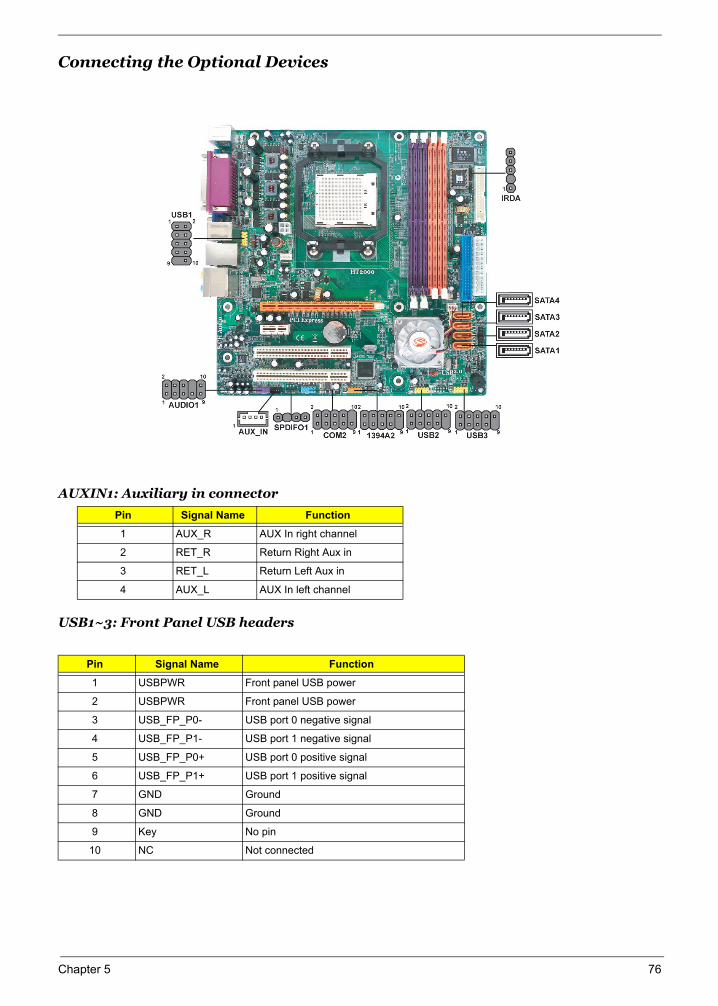
Connecting the Optional Devices
AUXIN1: Auxiliary in connector
USB1~3: Front Panel USB headers
Pin Signal Name Function
1 AUX_R AUX In right channel
2 RET_R Return Right Aux in
3 RET_L Return Left Aux in
4 AUX_L AUX In left channel
Pin Signal Name Function
1 USBPWR Front panel USB power
2 USBPWR Front panel USB power
3 USB_FP_P0- USB port 0 negative signal
4 USB_FP_P1- USB port 1 negative signal
5 USB_FP_P0+ USB port 0 positive signal
6 USB_FP_P1+ USB port 1 positive signal
7 GND Ground
8 GND Ground
9 Key No pin
10 NC Not connected
Chapter 5 76
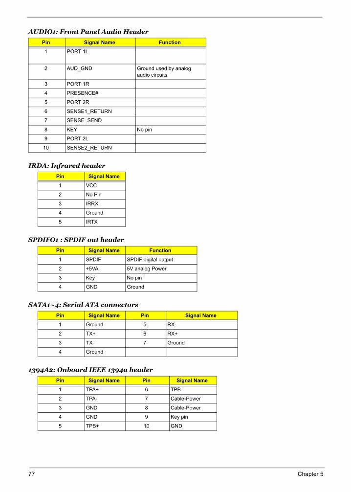
AUDIO1: Front Panel Audio Header
IRDA: Infrared header
SPDIFO1 : SPDIF out header
SATA1~4: Serial ATA connectors
1394A2: Onboard IEEE 1394a header
Pin Signal Name Function
1 PORT 1L
2 AUD_GND Ground used by analog audio circuits
3 PORT 1R
4 PRESENCE#
5 PORT 2R
6 SENSE1_RETURN
7 SENSE_SEND
8 KEY No pin
9 PORT 2L
10 SENSE2_RETURN
Pin Signal Name
1 VCC
2 No Pin
3 IRRX
4 Ground
5 IRTX
Pin Signal Name Function
1 SPDIF SPDIF digital output
2 +5VA 5V analog Power
3 Key No pin
4 GND Ground
Pin Signal Name Pin Signal Name
1 Ground 5 RX-
2 TX+ 6 RX+
3 TX- 7 Ground
4 Ground
Pin Signal Name Pin Signal Name
1 TPA+ 6 TPB-
2 TPA- 7 Cable-Power
3 GND 8 Cable-Power
4 GND 9 Key pin
5 TPB+ 10 GND
77 Chapter 5
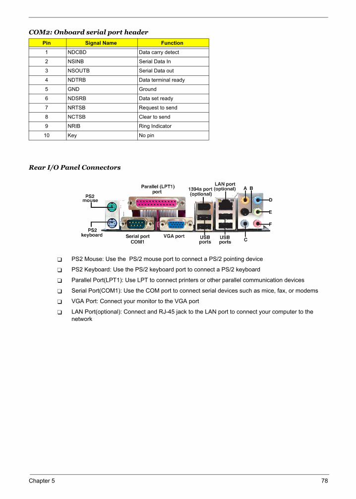
COM2: Onboard serial port header
Rear I/O Panel Connectors
PS2 Mouse: Use the PS/2 mouse port to connect a PS/2 pointing device
PS2 Keyboard: Use the PS/2 keyboard port to connect a PS/2 keyboard
Parallel Port(LPT1): Use LPT to connect printers or other parallel communication devices
Serial Port(COM1): Use the COM port to connect serial devices such as mice, fax, or modems
VGA Port: Connect your monitor to the VGA port
LAN Port(optional): Connect and RJ-45 jack to the LAN port to connect your computer to the network
Pin Signal Name Function
1 NDCBD Data carry detect
2 NSINB Serial Data In
3 NSOUTB Serial Data out
4 NDTRB Data terminal ready
5 GND Ground
6 NDSRB Data set ready
7 NRTSB Request to send
8 NCTSB Clear to send
9 NRIB Ring Indicator
10 Key No pin
Chapter 5 78
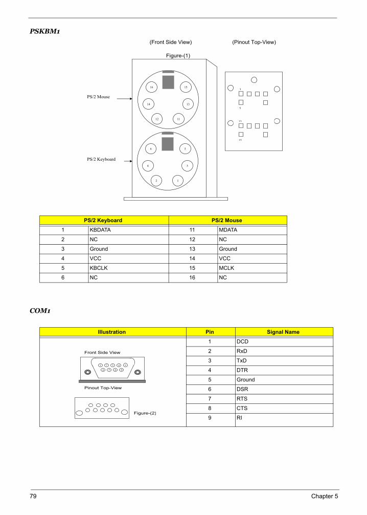
PSKBM1
COM1
PS/2 Keyboard PS/2 Mouse
1 KBDATA 11 MDATA
2 NC 12 NC
3 Ground 13 Ground
4 VCC 14 VCC
5 KBCLK 15 MCLK
6 NC 16 NC
Illustration Pin Signal Name
1 DCD
2 RxD
3 TxD
4 DTR
5 Ground
6 DSR
7 RTS
8 CTS
9 RI
(Front Side View) (Pinout Top-View)
Figure-(1)
16
14
12 11
15
13
6
4
2 1
5
3
3
5
13
15
PS/2 Mouse
PS/2 Keyboard
Front Side View
Pinout Top-View
Figure-(2)
1 2 3 4 5
6 7 8 9
79 Chapter 5
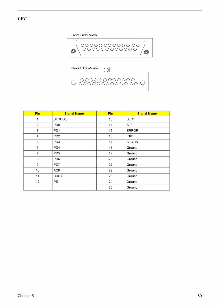
LPT
Pin Signal Name Pin Signal Name
1 STROBE 13 SLCT
2 PD0 14 ALF
3 PD1 15 ERROR
4 PD2 16 INIT
5 PD3 17 SLCTIN
6 PD4 18 Ground
7 PD5 19 Ground
8 PD6 20 Ground
9 PD7 21 Ground
10 ACK 22 Ground
11 BUSY 23 Ground
12 PE 24 Ground
25 Ground
Front Side View
Pinout Top-View
Chapter 5 80
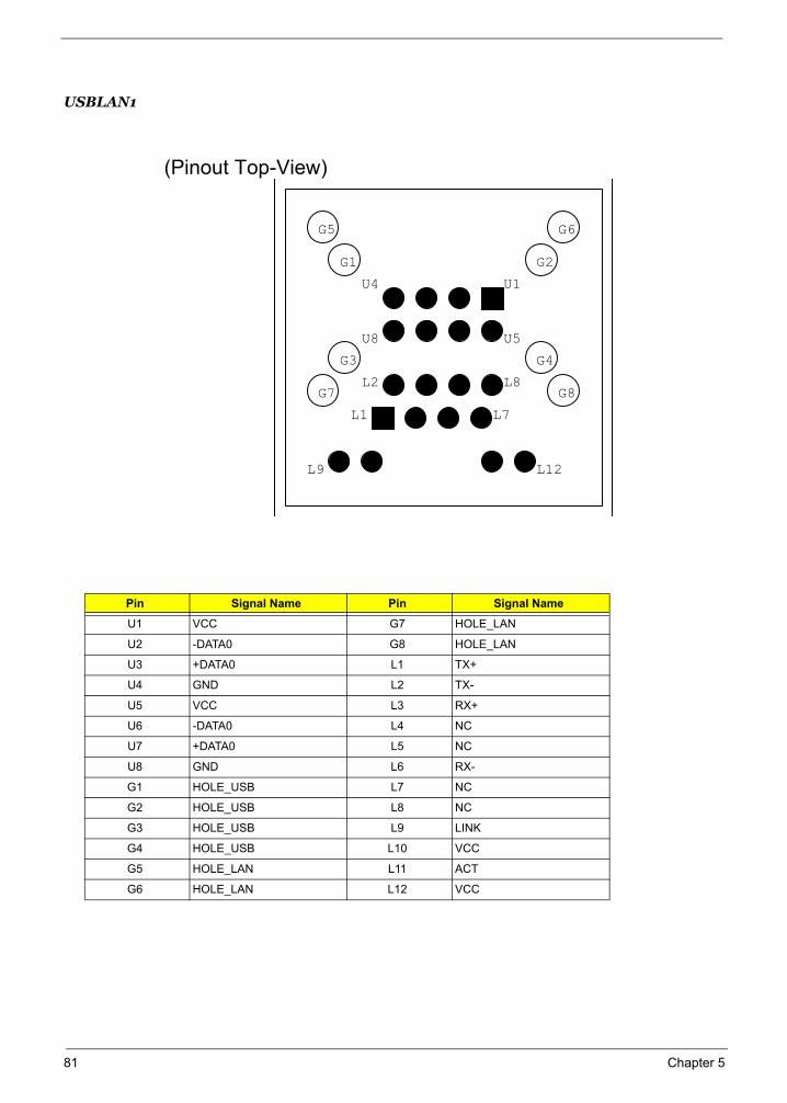
USBLAN1
Pin Signal Name Pin Signal Name
U1 VCC G7 HOLE_LAN
U2 -DATA0 G8 HOLE_LAN
U3 +DATA0 L1 TX+
U4 GND L2 TX-
U5 VCC L3 RX+
U6 -DATA0 L4 NC
U7 +DATA0 L5 NC
U8 GND L6 RX-
G1 HOLE_USB L7 NC
G2 HOLE_USB L8 NC
G3 HOLE_USB L9 LINK
G4 HOLE_USB L10 VCC
G5 HOLE_LAN L11 ACT
G6 HOLE_LAN L12 VCC
(Pinout Top-View)
U5
U1
U8
U4
L7
L8L2
L1
L12L9
G3
G2G1
G7
G6G5
G4
G8
81 Chapter 5
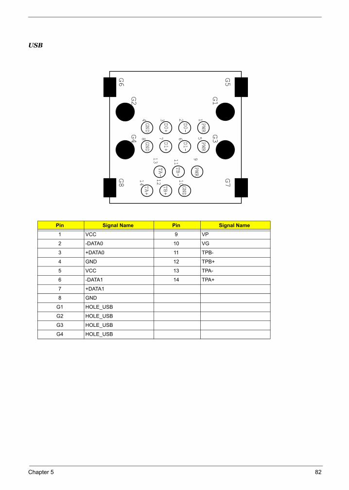
USB
Pin Signal Name Pin Signal Name
1 VCC 9 VP
2 -DATA0 10 VG
3 +DATA0 11 TPB-
4 GND 12 TPB+
5 VCC 13 TPA-
6 -DATA1 14 TPA+
7 +DATA1
8 GND
G1 HOLE_USB
G2 HOLE_USB
G3 HOLE_USB
G4 HOLE_USB
G2
TA-
G3
G5
G4
G8
G6
G7
PWR
TB+
TB-
GND
D1-
GND
PWR
D1+
PWR
D0+
D0-
TA+
GND
13 26 5
48 7
14
11
12
13
G1
9
10
Chapter 5 82

83 Chapter 5
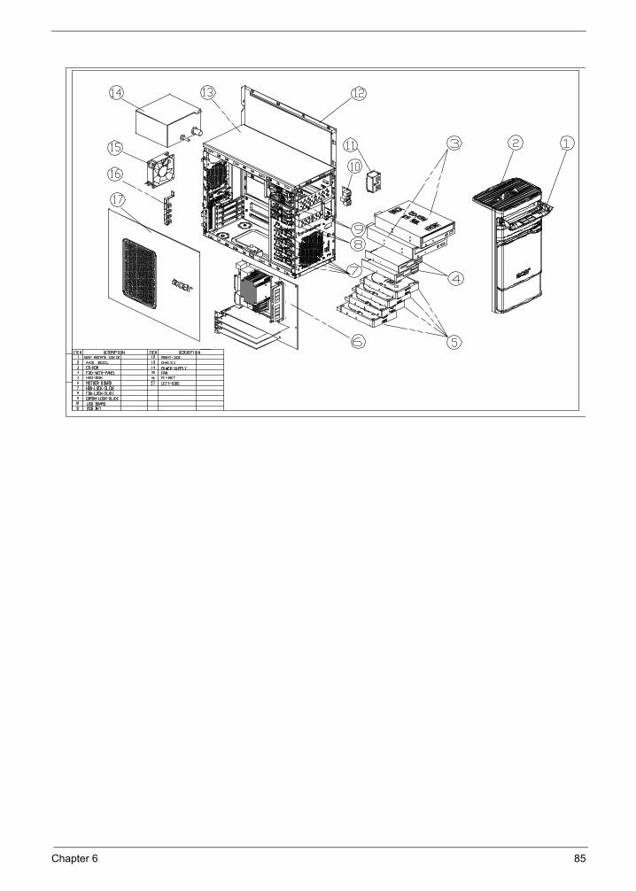
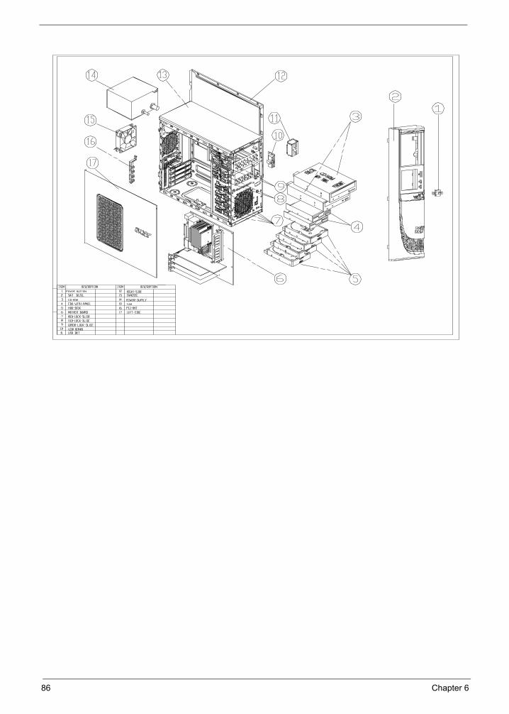
FRU (Field Replaceable Unit) List
Chapter 6
This chapter gives you the FRU (Field Replaceable Unit) listing in global configurations of Aspire T180/E380 and AcerPower M8. Refer to this chapter whenever ordering for parts to repair or for RMA (Return Merchandise Authorization).
IMPORTANT: Please note WHEN ORDERING FRU PARTS, that you should check the most up-to-date information available on your regional web or channel. For whatever reasons a part number change is made, it will not be noted in the printed Service Guide. For ACER-AUTHORIZED SERVICE PROVIDERS, your Acer office may have a DIFFERENT part number code to those given in the FRU list of this printed Service Guide. You MUST use the local FRU list provided by your regional Acer office to order FRU parts for repair and service of customer machines.
IMPORTANT: Please note that Acer Corporation sells only the parts listed in the following table. Please be reminded that though some parts are disassembled in Chapter 3 for demonstration purpose, Acer Corporation does not provide these parts.
NOTE: To scrap or to return the defective parts, you should follow the local government ordinance or regulations on how best to dispose it, or follow the rules set by your regional Acer office on how to return it.You can access to the website for the latest Parts version http://aicsl.acer.com.tw/spl/
NOTE: The final version of SPL will be released later.
Chapter 6 83
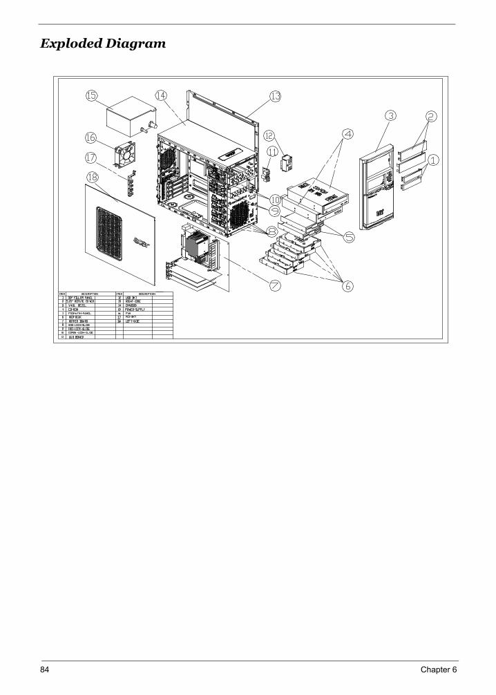
Exploded Diagram
84 Chapter 6
Chapter 6 85
86 Chapter 6

FRU ListThe FRU list will be updated later.
Chapter 6 87