Embed Size (px)
Citation preview
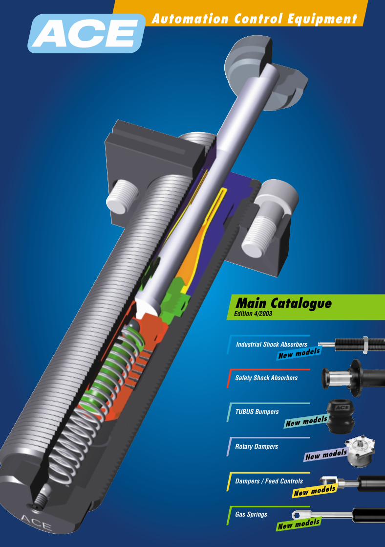
Automation Control Equipment
Rotary Dampers
Dampers / Feed Controls
Gas Springs
Main CatalogueEdition 4/2003
ACE Controls International, Belvedere Road, Newton-Le-Willows, Merseyside, WA12 OJJTel: 01925 227171 · Fax: 01925 229323 · e mail: [email protected] · www.ace-controls.co.uk
Ind
ust
ria
l Sh
ock
Ab
sorb
ersACE worldwide
New models
New models
TUBUS Bumpers
Industrial Shock Absorbers
New models
Safety Shock Absorbers
New models
New models
ARGENTINACAMOZZI NEUMATICA S.A.
Prof. Dr. Pedro Chutro 3048 c1437iyj Buenos Aires República Argentina Tel.: (00 54) 11 49 11 08 16 Fax: (00 54) 11 49 12 41 91
AUSTRALIAIMI NORGREN LTD.
33 South Corporate Av. Rowville, Victoria 3178, AustraliaTel.: (00 61) 3 92 13 08 00Fax: (00 61) 3 92 13 08 98
AUSTRIAIMI NORGREN GES.M.B.H.
A-2355 Wiener NeudorfIndustriezentrum NÖ-Süd, Straße 2Tel.: (00 43) 22 36-6 35 20-0Fax: (00 43) 22 36-6 35 20-20
BRAZILOBR EQUIPAMENTOS
INDUSTRIAIS LTDA.Rua Comendador Roberto Ugolini, 440-Mooca,Sao Paulo SP, CEP-03.125-010 Brazil Tel.: (00 55) 11 69 14 36 98 Fax: (00 55) 1 12 73 01 30
BELGIUMACE STOSSDÄMPFER GMBH
Herzogstraße 26-28, D-40764 LangenfeldPostfach 1510, D-40740 Langenfeld Tel.: (00 49) 21 73-92 26 10Fax: (00 49) 21 73-92 26 19(Vertriebspartner auf Anfrage)
CANADACOWPER, LTD.
677 7th Avenue, Lachine, Quebec H8S 3A1Tel.: (0 01) 5 14-6 37-67 46Fax: (0 01) 5 14-6 37-50 55
CHILETAYLOR
AUTOMATIZACION S. A.A.V. Vicuna Mackenna # 1589Santiago, Chile Tel.: (00 56) 25 55 15 16Fax: (00 56) 25 44 19 65
CROATIA AND BOSNIA BIBUS ZAGREB D.O.O.
Anina 91, HR-1000 Zagreb, CroatiaTel.: (00 385) 13 81 80 06Fax: (00 385) 13 81 80 05
CZECH REPUBLICBIBUS S.R.O.
Videnska 125, CZ-63927 Brno, Czech RepublicTel.: (0 04 20) 5 47 12 53 00Fax: (0 04 20) 5 47 12 53 10
DENMARKAVN PNEUMATIK A/S
Suensonsvej 14, DK-8600 Silkeborg, Denmark Tel.: (00 45) 70 20 04 11Fax: (00 45) 87 22 81 00
FINLANDNESTEPAINE OY
Makituvantie 11, FIN-01510 Vantaa, Finland Tel.: (0 03 58) 9 61 36 33Fax: (0 03 58) 9 61 36 36 66
FRANCEBIBUS DOEDIJNS
ZI du ChapotinF-69970 Chaponnay FranceTel.: (00 33) 4 78 96 80 00Fax: (00 33) 4 78 96 80 01
GERMANYACE STOSSDÄMPFER GMBH
Herzogstraße 26-28, D-40764 LangenfeldPostfach 1510, D-40740 Langenfeld Tel.: (00 49) 21 73-92 26 10Fax: (00 49) 21 73-92 26 19(Vertriebspartner auf Anfrage)
GREECEPNEUMATEC
INDUSTRIAL AUTOMATION SYSTEMSNevrokopiu 18, 11855 Athens Greece Tel.: (00 302) 1 03412101/3413930Fax: (00 302) 1 03413930
HONGKONGIMI NORGREN LIMITED
6th Floor, Benson Tower74 Hung To Road, Kwun Tong Kowloon, Hong KongTel.: (0 08 52) 24 92 76 08Fax: (0 08 52) 24 98 58 78
HUNGARYYERUHAM MUVEK KFT.
1133 Budapest, XIII. district, Visegradi str. 114, 2000, Szentendre, HungaryTel.: (00 36) 1-4 12-41 61Fax: (00 36) 1-4 20-41 71
BIBUS KFT.HU-1103 Budapest, Újhegyi út 2, Hungary Tel.: (00 36) 1265 27 33 Fax: (00 36) 1264 89 00
INDIAMACO CORPORATION (INDIA)
PVT LTD. 2/5 Sarat Bose Road,”Sukhsagar” 7th Floor, 7A, Kolkata - 700 020Calcutta, IndiaTel.: (00 91) 33 24 75 83 71/85 00/24 54 32 81Fax: (00 91) 33 24 54 32 69
3D EQUIPMENT508 Maheshwari Chambers 6-3-650 Somajiguda Hyderabad, 500 082 India Tel.: (00 91) 4 06 66 81 09 Fax: (00 91) 4 03 35 86 93
IRELANDIRISH PNEUMATIC
SERVICES LTD.Unit 2014, City West Business CampusSaggart, Co. Dublin, IrelandTel.: (0 03 53) 14 66 02 00Fax: (0 03 53) 14 66 01 58
ISRAELILAN & GAVISH
AUTOMATION SERVICE LTD.24, Shenkar Street, Qiryat-arie 49513, IsraelP.O. Box 10118, Petha-Tiqva 49001, IsraelTel.: (0 09 72) 39 22 18 24Fax: (0 09 72) 39 24 07 61
ITALYR.T.I. S.R.L.
Via Chambery 93/107V, 10142 Turin, Italy Tel.: (00 39) 011-70 00 53/70 02 32Fax: (00 39) 011-70 01 41
JAPANACE CONTROLS JAPAN LTD.
261-1-102 Tamasaki, Ichihara CityChiba Pref. 290, JapanTel.: (00 81) 4 36 24 67 11Fax: (00 81) 4 36 24 67 12
JORDANATAFAWOK TRADING EST.
P.O. Box 921797, Amman 11192, JordanTel.: (0 09 62) 64 02 38 73Fax: (0 09 62) 65 92 63 25
KOREASEYANG CORPORATION
1243-5, Jungwang-DongSilheung City, Kyunggi- Do/KoreaTel.: (00 82) 31 498 0121Fax: (00 82) 31 498 0172
LUXEMBOURGACE STOSSDÄMPFER GMBH
Herzogstraße 26-28, D-40764 LangenfeldPostfach 1510, D-40740 Langenfeld Tel.: (00 49) 21 73-92 26 10Fax: (00 49) 21 73-92 26 19(Vertriebspartner auf Anfrage)
MALAYSIAHOERBIGER-ORIGA SDN BHD
12 Jalan USJ 7 / 3A 47610 UEP Subang Jaya Selangor Darul Ehsan, Malaysia Tel.: (00 60) 37 34 78 22/7 31 59 45Fax: (00 60) 37 34 78 23
IMI NORGREN PTE. LTD.16 Tuas Street, Singapore 638453Tel.: (00 65) 68 62 18 11Fax: (00 65) 68 62 18 86
MEXICOKOPAR S.A. DE C.V.
Angel Martinez Villarreal # 425Col. Chepevera, Monterrey, N.LMexico 64030Tel.: (00 52) (81) 83 48 73 83Fax: (00 52) (81) 83 46 14 32
NETHERLANDSACE STOSSDÄMPFER GMBH
Herzogstraße 26-28, D-40764 LangenfeldPostfach 1510, D-40740 Langenfeld Tel.: (00 49) 21 73-92 26 10Fax: (00 49) 21 73-92 26 19(Vertriebspartner auf Anfrage)
NEW ZEALANDIMI NORGREN (N.Z.) LTD.
3-5 Walls Road P. O. Box 12-893, Penrose, AucklandTel.: (00 64) 95 79 01 89Fax: (00 64) 95 26 33 99
NORWAYOILTECH AS.
Dynamitveien 23, Postboks 133N-1401 Ski, NorwayTel.: (00 47) 64 91 11 80Fax: (00 47) 64 87 43 21
PAKISTANJ.J. HYDRAULICS &
PNEUMATICSHotel Metropole Bldg.Room 127, 1st Floor Club RoadKarachi, Pakistan 75520Tel.: (00 92) 2 15 66 10 63Fax: (00 92) 2 15 66 10 65
POLANDBIBUS MENOS SP.Z.O.O.
ul. Tadeusza Wendy 7/9PL-81-341 Gdynia, PolandTel.: (00 48) 5 86 60 95 70Fax: (00 48) 5 86 61 71 32
PORTUGALAIRCONTROL S.A.
Paseo Sarroeta 4E-20014 San Sebastian, SpainTel.: (00 34) 9 43 44 50 80Fax: (00 34) 9 43 44 51 53
PUERTO RICOP & C COMPANY
P.O. Box 120Canovanas, Puerto Rico 00729Tel.: (00 17 87) 7 68 50 33Fax: (00 17 87) 7 50 68 20
SINGAPOREHOERBIGER-ORIGA PTE. LTD.Block 5012 Ang Mo Kio Avenue
5#05-01TECHplace llSingapore 569876Tel.: (00 65) 64 83 29 59Fax: (00 65) 64 83 29 79
IMI NORGREN PTE. LTD.16 Tuas Street, Singapore 638453Tel.: (00 65) 68 62 18 11Fax: (00 65) 68 62 18 86
SLOVAKIABIBUS SK, S.R.O.
Priemyselna 4, SK-94901 Nitra, SlovakiaTel.: (0 04 21) 37-741-2525Fax: (0 04 21) 37-516-6701
SLOVENIAINOTEH D. O. O.
Vorohova 20, SI-2345 Bistrica ob DraviSloveniaTel.: (0 03 86) 02 665 1131Fax: (0 03 86) 02 665 2081
SOUTH AFRICAISANDO PNEUMATICS
(PTY) LTD.1, Skietlood Street, Isando ext. 3P.O. Box 441, Isando 1600, South AfricaTel.: (00 27) 1 19 74 51 76Fax: (00 27) 1 19 74 61 37
SPAINAIRCONTROL S. A.
Paseo Sarroeta 4E-20014 San Sebastian, SpainTel.: (00 34) 9 43 44 50 80Fax: (00 34) 9 43 44 51 53
SWEDENHYDNET AB
Turebergsvagen 5S-191 47 Sollentuna, SwedenTel.: (00 46) 8 59 47 04 70Fax: (00 46) 8 59 47 04 79
SWITZERLANDBIBUS AG
Hertistraße 1CH-8304 Walisellen, SwitzerlandTel.: (00 41) 18 77 50 11Fax: (00 41) 18 77 50 19
TAIWANDANYAO TRADING
COMPANY LTD.7F, NO. 19, Chung-Cheng RoadHsin-Chuang City, 242Taipei County, TaiwanTel.: (0 08 86) 2 22 76 82 00Fax: (0 08 86) 2 22 76 75 73
THAILANDB-TAC AUTOMATION
LTD. PART.2036/42 SOI 60/2 Sukhumvit Rd10250 BangkokTel.: (00 66) 2-33 19 06 24Fax: (00 66) 2-33 32 38 70
TURKEYT.M.G. PNEUMATIC &
HYDRAULIC LTD. Necatibey Cad No. 5480030 Karakoy, TurkeyTel.: (00 90) 21 22 93 82 00Fax: (00 90) 21 22 49 88 34
USAACE CONTROLS
INTERNATIONAL INC.P.O. Box 71, FarmingtonUSA-Michigan 48024 (and in all states)Tel.: (0 01) 2 48-4 76-02 13Fax: (0 01) 2 48-4 76-24 70

World Leader in Motion Control
Controls International · Belvedere Road · Newton-le-Willows · WA12 0JJ · Tel 01925 227171 · Fax 01925 229323 · E-mail [email protected] 131
Further Information and Local Contacts
For over 30 years ACE has been
acknowledged as the world leader in
motion control.
It was back in the 1960’s that the thenunique ACE shock absorber was initiallydesigned to serve the Detroit automotive industry. Since then, our world-renowned shock absorbers havegrown to some 100 different models. Inaddition, the ACE motion control rangehas developed to include safety shockabsorbers, rotary dampers, hydraulicdampers, feed controls and industrial gas springs.
LIFETIME WARRANTY
ACE was the first manufacturer in itssector to offer a lifetime warranty on allof its products. ACE products are designed and manufactured to ISO 9001 and are guaranteed to be free from defects in materials or workmanship. ACE will repair or replaceany of its products determined to havea defect in materials or workmanship atany time for the life of the product.
PRODUCT IMPROVEMENT
Due to a continuous product improvement policy, the company reserves the right to change a product’sspecification without notice.
CUSTOMER SUPPORT
ACE employs over 250 people throughout its global network comprising offices in the UK, Germanyand Japan plus distributors in 85 NorthAmerican cities and 33 additional countries.
The UK office carries an extensive stockof products and spare parts, so customers can always rely on a quick and effective service. In addition, the approved ACE distributors and team ofarea managers shown on the inside back cover are always on hand to advise on product selection and any other aspect of the range.
APPLICATION SIMULATION
AND COMPUTER SELECTION
ACE has developed a sophisticated suite of computer software. By combining application data with a shock absorber’s design parameters, ACE engineers can create an accurate picture of how a particular shock absorber will perform under any set ofapplication conditions. Peak reaction force, peak deceleration, time through stroke and velocity decay can be plotted with extreme accuracy (see below). The user benefits by having anyguesswork taken out of sizing decisionsand by knowing before installation, exactly how his shock problem will be solved.
Simulation can also be used to maximise the performance of ACE adjustable models by predicting the ideal adjustment setting for a particulargroup of operating conditions.
Copies of our computer selection programme are available, free of charge. The software provides quick and easy selection of the correct ACE shock absorber for your application.
For more complex or unusual applications full technical support and advice is always freely available.
FAX Request
Company
Address
Postcode.
Telephone/Fax.
Contact name/Dept.
YES! We are interested in:
further copy of the new ACE Catalogue.
the new ACE CAD-Library with Selectionprogramme on CD-Rom. 2D- and 3D-Version (standard formats).
Training at our site.
Technical assistance at our site.
Please quote for: (attach details)
FAX
to 0
1925 2
29323UK Sales Manager
Edward AbbottTel: 07802 232 630Fax: 01270 877002E-mail: [email protected]
ACE Area Managers
NORTH
Paul CorkillTel: 07802 926 431Fax: 0151 283 8710E-mail: [email protected]
MIDLANDS
Darren HarperTel: 07764 357 495Fax: 01623 652 920E-mail: [email protected]
SOUTH EAST
Paul ConstableTel: 07802 926 429Home: 01342 311 171Fax: 01342 316 119E-mail: [email protected]
SOUTH WEST
Malcolm SharlandTel: 07802 926 430Fax: 02920 860 115E-mail: [email protected]
Controls International · Belvedere Road · Newton-le-Willows · WA12 0JJ · Tel 01925 227171 · Fax 01925 229323 · E-mail [email protected]
EditorialIs
sue
4.20
03 S
pec
ific
atio
ns
sub
ject
to
ch
ang
e
3
3
Dear Reader,
This catalogue presents all aspects of damping and deceleration methods you need to reduceharmful and destructive energies effectively. ACE offers coordinated deceleration systems that helpyou to attain increased productivity, longer service life, greater power and speeds for your drives,motors, or systems.
Current Productivity studies show that over 36 % of production stoppages are due to necessary repair work. Protect yourself by installing ACE safety elements that are part of ACE’s extensive product range.
ACE maintains its position as the Market Leader in motion control technology and sets the trend towards smaller and higher performance control components.
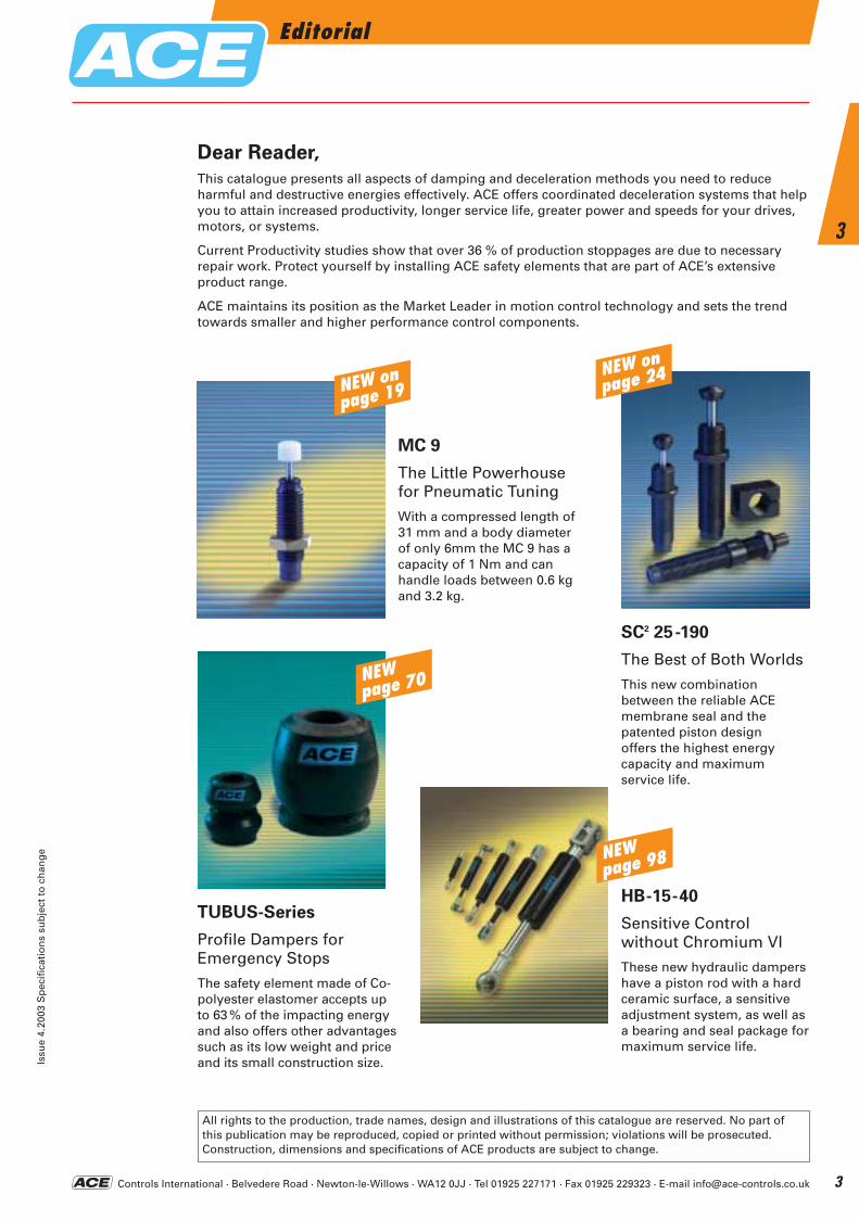
SC2 25-190
The Best of Both Worlds
This new combinationbetween the reliable ACEmembrane seal and thepatented piston designoffers the highest energycapacity and maximumservice life.
TUBUS-Series
Profile Dampers forEmergency Stops
The safety element made of Co-polyester elastomer accepts upto 63 % of the impacting energyand also offers other advantagessuch as its low weight and priceand its small construction size.
All rights to the production, trade names, design and illustrations of this catalogue are reserved. No part ofthis publication may be reproduced, copied or printed without permission; violations will be prosecuted.Construction, dimensions and specifications of ACE products are subject to change.
HB-15-40
Sensitive Control without Chromium VI
These new hydraulic dampershave a piston rod with a hardceramic surface, a sensitiveadjustment system, as well asa bearing and seal package formaximum service life.
MC 9
The Little Powerhousefor Pneumatic Tuning
With a compressed length of31 mm and a body diameterof only 6mm the MC 9 has acapacity of 1 Nm and canhandle loads between 0.6 kgand 3.2 kg.
NEW onpage 19
NEW onpage 24
NEWpage 70
NEWpage 98
ACE-Kat_2003_UK_003-007 23.09.2003 10:13 Uhr Seite 3

Controls International · Belvedere Road · Newton-le-Willows · WA12 0JJ · Tel 01925 227171 · Fax 01925 229323 · E-mail [email protected]
Major Customers
Issu
e 4.
2003
Sp
ecif
icat
ion
s su
bje
ct t
o c
han
ge
4
4
ACE-Kat_2003_UK_003-007 23.09.2003 10:14 Uhr Seite 4
Controls International · Belvedere Road · Newton-le-Willows · WA12 0JJ · Tel 01925 227171 · Fax 01925 229323 · E-mail [email protected]
IndexIs
sue
4.20
03 S
pec
ific
atio
ns
sub
ject
to
ch
ang
e
5
56 - 5960 - 6364 - 67
6869
SCS-33 to 64SCS-38 to 63CB-63 to 160Operating instructionsApplication examples
34678 NEW9
1011 - 1213 - 1516 - 17
Page
106 - 108109 - 117 NEW118 - 119
120 NEW121 - 124
125 NEW126 - 127
128 NEW129130131
92 - 93 NEW9495
96 - 9798 -103 NEW
104105
General
VC 25FA, MA and MVCApplication examplesDVCHB-15 to 70TD-28 and TDE-28Application examples
Industrial Shock Absorbers
70 - 71 NEW72 - 73 NEW74 - 75 NEW76 - 77 NEW78 - 79 NEW
8081
TA 12 to 116TS 14 to 107TR 29 to 100TR-L 66 to 188TC 64 to 176Profile dampers – overviewApplication examples
Rotary Dampers
Hydraulic Dampers and Feed Controls
Industrial Gas Springs
Safety Shock Absorbers
TUBUS-Profile Dampers
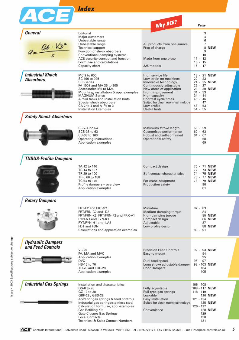
EditorialMajor customersUnbeatable rangeUnbeatable rangeTechnical supportFunction of shock absorbersConventional damping systemsACE security concept and functionFormulae and calculationsCapacity chart
All products from one sourceFree of charge
Made from one piece
225 models
MC 9 to 600SC 190 to 925SC2-SeriesFA 1008 and MA 35 to 900Accessories M6 to M25Mounting, installation & app. examplesMAGNUM-SeriesAir/Oil tanks and installation hintsSpecial shock absorbersCA 2 to 4 and A11/2 to 3Installation Examples
High service lifeLow strain on machinesInnovative technologyContinuously adjustableNew areas of applicationProfit improvementHigh-capacityShortest cycle timesSuited for clean room technologyLow profileUseful hints
Maximum stroke lengthCustomised performanceRobust and self-containedOperational safety
Compact design
Soft contact characteristics
For crane equipmentProduction safety
MiniatureMedium-damping torqueHigh-damping torqueCompact designAdjustableLow profile design
Precision Feed ControlsEasy to mount
Dual feed speedLong stroke adjustable damperDoor Dampers
Fully adjustablePull type gas springsLockableEasy installationSuited for clean room technology
Convenience
18 - 21 NEW22 - 2324 - 25 NEW26 - 2728 - 30 NEW31 - 3334 - 4445 - 46
4748 - 5354 - 55
82 - 838485 NEW86 NEW8788 NEW
89 - 91
FRT-E2 and FRT-G2FRT/FRN-C2 and -D2FRT/FRN-K2, FRT/FRN-F2 and FRX-A1FYN-N1 and FYN-K1FYT/FYN-H1 and -LA3FDT and FDNCalculations and application examples
Installation and characteristicsGS-8 to 70GZ-19 to 28GBF-28 / GBS-28Acc's for gas springs & feed controlsIndustrial gas springs/stainless steelCalculation formulae, app. examplesGas Refilling KitGate Closure Gas SpringsLocal ContactsTechnical & Sales Contact Numbers
Why ACE?
ACE-Kat_2003_UK_003-007 23.09.2003 10:14 Uhr Seite 5
Controls International · Belvedere Road · Newton-le-Willows · WA12 0JJ · Tel 01925 227171 · Fax 01925 229323 · E-mail [email protected]
An Unbeatable RangeFinest Available
Issu
e 4.
2003
Sp
ecif
icat
ion
s su
bje
ct t
o c
han
ge
6
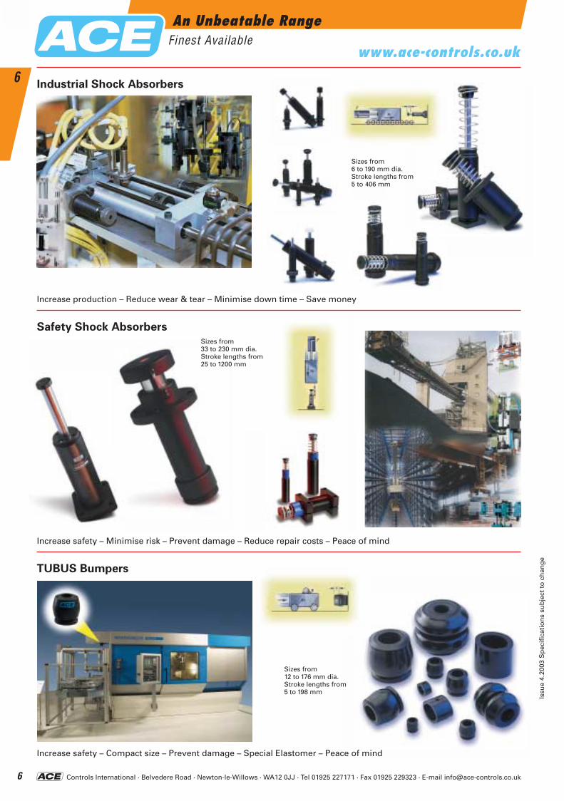
6Industrial Shock Absorbers
Safety Shock Absorbers
Increase production – Reduce wear & tear – Minimise down time – Save money
TUBUS Bumpers
Increase safety – Minimise risk – Prevent damage – Reduce repair costs – Peace of mind
Increase safety – Compact size – Prevent damage – Special Elastomer – Peace of mind
Sizes from 12 to 176 mm dia.Stroke lengths from 5 to 198 mm
Sizes from 33 to 230 mm dia.Stroke lengths from 25 to 1200 mm
Sizes from 6 to 190 mm dia.Stroke lengths from 5 to 406 mm
www.ace-controls.co.uk
ACE-Kat_2003_UK_003-007 23.09.2003 10:14 Uhr Seite 6
Controls International · Belvedere Road · Newton-le-Willows · WA12 0JJ · Tel 01925 227171 · Fax 01925 229323 · E-mail [email protected]
7
Issu
e 4.
2003
Sp
ecif
icat
ion
s su
bje
ct t
o c
han
ge
7
An Unbeatable RangeFinest Available
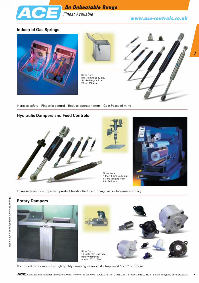
Industrial Gas Springs
Hydraulic Dampers and Feed Controls
Increase safety – Fingertip control – Reduce operator effort – Gain Peace of mind
Rotary Dampers
Increased control – Improved product finish – Reduce running costs – Increase accuracy
Controlled rotary motion – High quality damping – Low cost – Improved “Feel” of product
Sizes from 10 to 80 mm Body dia.Rotary damping about 105° to 360°
Sizes from 8 to 70 mm Body dia.Stroke lengths from 20 to 1000 mm
Sizes from 10 to 70 mm Body dia.Stroke lengths from 8 to 800 mm
www.ace-controls.co.uk
ACE-Kat_2003_UK_003-007 23.09.2003 10:15 Uhr Seite 7
Controls International · Belvedere Road · Newton-le-Willows · WA12 0JJ · Tel 01925 227171 · Fax 01925 229323 · E-mail [email protected]
Technical SupportFinest Available
Issu
e 4.
2003
Sp
ecif
icat
ion
s su
bje
ct t
o c
han
ge
8
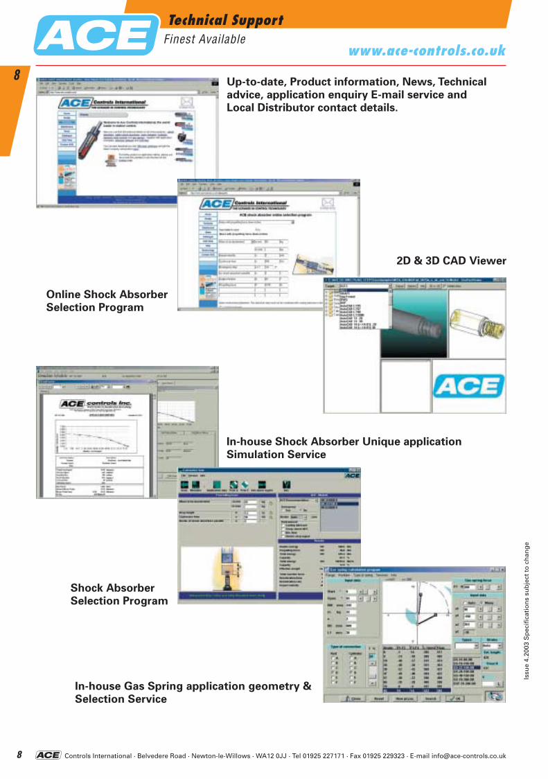
8Up-to-date, Product information, News, Technical
advice, application enquiry E-mail service and
Local Distributor contact details.
Online Shock Absorber
Selection Program
2D & 3D CAD Viewer
In-house Shock Absorber Unique application
Simulation Service
Shock Absorber
Selection Program
In-house Gas Spring application geometry &
Selection Service
www.ace-controls.co.uk
ACE-Kat_2003_UK_008-013 22.09.2003 16:56 Uhr Seite 8
Controls International · Belvedere Road · Newton-le-Willows · WA12 0JJ · Tel 01925 227171 · Fax 01925 229323 · E-mail [email protected]
Virtually all manufacturing processes involve movement of some kind. In production machinery this can involve linear transfers, rotary index motions, fast feeds etc. At some point these motions change direction or come to a stop.
Any moving object possesses kinetic energy as a result of its motion and if the object changes direction or is brought to rest, the dissipation of this kinetic energy can result in destructive shock forces within the structural and operating parts of the machine.
Kinetic energy increases as the square of the speed and the heavier the object, or the faster it travels, the more energy it has. An increase in pro-duction rates is only possible by dissipating this kinetic energy smoothly and thereby eliminating destructive deceleration forces.
Older methods of energy absorption such as rubber buffers, springs, hydraulic dashpots and cylinder cushions do not provide this required smooth deceleration characteristic – they are non linear and produce high peak forces at some point during their stroke.
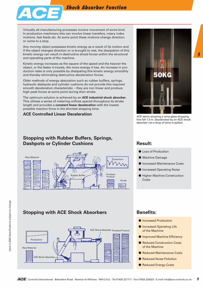
The optimum solution is achieved by an ACE industrial shock absorber.This utilises a series of metering orifices spaced throughout its strokelength and provides a constant linear deceleration with the lowest possible reaction force in the shortest stopping time.
ACE Controlled Linear DecelerationACE demo showing a wine glass droppingfree fall 1.3 m. Decelerated by an ACE shockabsorber not a drop of wine is spilled.
Stopping with Rubber Buffers, Springs,Dashpots or Cylinder Cushions
Stopping with ACE Shock Absorbers
Result:
Benefits:
● Loss of Production
● Machine Damage
● Increased Maintenance Costs
● Increased Operating Noise
● Higher Machine Construction Costs
● Increased Production
● Increased Operating Lifeof the Machine
● Improved Machine Efficiency
● Reduced Construction Costsof the Machine
● Reduced Maintenance Costs
● Reduced Noise Pollution
● Reduced Energy Costs
Raw Material
Production
Finished ProductACE Shock Absorber
ACE Shock Absorber
Raw MaterialProduction
Rubber Buffer FinishedProduct
Scrap
Shock Absorber FunctionIs
sue
4.20
03 S
pec
ific
atio
ns
sub
ject
to
ch
ang
e
9
9
ACE-Kat_2003_UK_008-013 22.09.2003 16:56 Uhr Seite 9
Controls International · Belvedere Road · Newton-le-Willows · WA12 0JJ · Tel 01925 227171 · Fax 01925 229323 · E-mail [email protected]
Comparison of Damping Systems
Issu
e 4.
2003
Sp
ecif
icat
ion
s su
bje
ct t
o c
han
ge
10
10
t
t
Q
Q
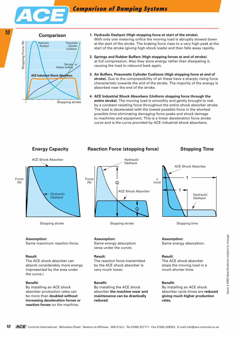
1. Hydraulic Dashpot (High stopping force at start of the stroke).
With only one metering orifice the moving load is abruptly slowed down at the start of the stroke. The braking force rises to a very high peak at the start of the stroke (giving high shock loads) and then falls away rapidly.
2. Springs and Rubber Buffers (High stopping forces at end of stroke).
at full compression. Also they store energy rather than dissipating it, causing the load to rebound back again.
3. Air Buffers, Pneumatic Cylinder Cushions (High stopping force at end of
stroke). Due to the compressibility of air these have a sharply rising force characteristic towards the end of the stroke. The majority of the energy is absorbed near the end of the stroke.
4. ACE Industrial Shock Absorbers (Uniform stopping force through the
entire stroke). The moving load is smoothly and gently brought to rest by a constant resisting force throughout the entire shock absorber stroke. The load is decelerated with the lowest possible force in the shortest possible time eliminating damaging force peaks and shock damage to machines and equipment. This is a linear deceleration force stroke curve and is the curve provided by ACE industrial shock absorbers.
Assumption:
Same maximum reaction force.
Result:
The ACE shock absorber can absorb considerably more energy(represented by the area under the curve.)
Benefit:
By installing an ACE shock absorber production rates can be more than doubled without
increasing deceleration forces or
reaction forces on the machine.
Assumption:
Same energy absorption (area under the curve).
Result:
The reaction force transmitted by the ACE shock absorber is very much lower.
Benefit:
By installing the ACE shock absorber the machine wear and
maintenance can be drastically
reduced.
Assumption:
Same energy absorption.
Result:
The ACE shock absorber stops the moving load in a much shorter time.
Benefit:
By installing an ACE shock absorber cycle times are reduced
giving much higher production
rates.
Energy Capacity Reaction Force (stopping force) Stopping Time
Force(N)
Force (N)
Stopping stroke Stopping stroke Stopping time
HydraulicDashpot
HydraulicDashpot
ACE Shock Absorber
v(m/s)
ACE Shock Absorber
HydraulicDashpot
Comparison
ACE Shock Absorber
Stopping stroke
HydraulicDashpot
ACE Industrial Shock Absorbers
PneumaticCylinder
Cushions
Sto
pp
ing
Fo
rce
(N)
Springs - orRubber buffers
ACE-Kat_2003_UK_008-013 22.09.2003 16:56 Uhr Seite 10
Controls International · Belvedere Road · Newton-le-Willows · WA12 0JJ · Tel 01925 227171 · Fax 01925 229323 · E-mail [email protected]
The Benefits of Good DesignIs
sue
4.20
03 S
pec
ific
atio
ns
sub
ject
to
ch
ang
e
11
11
Other Shock Absorber
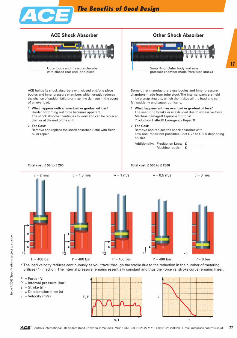
Some other manufacturers use bodies and inner pressurechambers made from tube stock.The internal parts are heldin by a snap ring etc. which then takes all the load and can fail suddenly and catastrophically.
1. What happens with an overload or gradual oil loss?
The snap ring breaks or is extruded due to excessive force.Machine damage!! Equipment Stops!!Production Halted!! Emergency Repair!!
2. The Cost:
Remove and replace the shock absorber with new one (repair not possible). Cost £ 75 to £ 300 dependingon size.
Additionally: Production Loss: £ _________Machine repair: £ _________
Total cost: £ 500 to £ 2000
ACE Shock Absorber
ACE builds its shock absorbers with closed end/one piece bodies and inner pressure chambers which greatly reduces the chance of sudden failure or machine damage in the eventof an overload.
1. What happens with an overload or gradual oil loss?
Harder bottoming out force becomes apparent. The shock absorber continues to work and can be replacedthen or at the end of the shift.
2. The Cost:
Remove and replace the shock absorber. Refill with fresh oil or repair.
Total cost: £ 50 to £ 200
P = 400 bar P = 400 bar P = 400 bar P = 400 bar P = 0 bar
* The load velocity reduces continuously as you travel through the stroke due to the reduction in the number of metering orifices (*) in action. The internal pressure remains essentially constant and thus the Force vs. stroke curve remains linear.
F = Force (N)P = Internal pressure (bar)s = Stroke (m)t = Deceleration time (s)v = Velocity (m/s)
Outer body and Pressure chamberwith closed rear end (one-piece)
Snap Ring (Outer body and inner pressure chamber made from tube stock.)
*4 *3 *2 *1 *0
n
n
n
n n
n
n
n
n
n
v = 2 m/s v = 1,5 m/s v = 1 m/s v = 0,5 m/s v = 0 m/s
F / P v
s / t t
ACE-Kat_2003_UK_008-013 22.09.2003 16:56 Uhr Seite 11
Controls International · Belvedere Road · Newton-le-Willows · WA12 0JJ · Tel 01925 227171 · Fax 01925 229323 · E-mail [email protected]
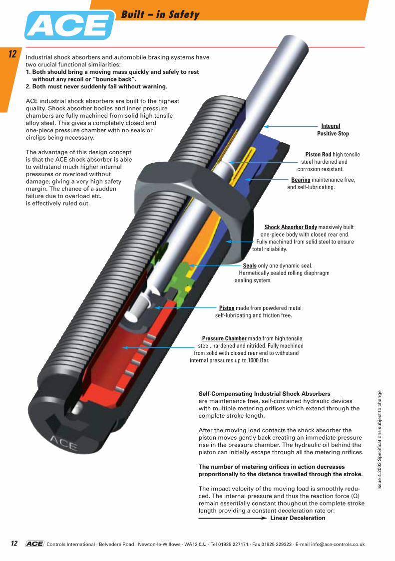
IntegralPositive Stop
Built – in Safety
Issu
e 4.
2003
Sp
ecif
icat
ion
s su
bje
ct t
o c
han
ge
12
12 Industrial shock absorbers and automobile braking systems havetwo crucial functional similarities:1. Both should bring a moving mass quickly and safely to rest
without any recoil or “bounce back”.
2. Both must never suddenly fail without warning.
ACE industrial shock absorbers are built to the highest quality. Shock absorber bodies and inner pressure chambers are fully machined from solid high tensile alloy steel. This gives a completely closed end one-piece pressure chamber with no seals or circlips being necessary.
The advantage of this design concept is that the ACE shock absorber is able to withstand much higher internal pressures or overload without damage, giving a very high safety margin. The chance of a sudden failure due to overload etc. is effectively ruled out.
Self-Compensating Industrial Shock Absorbers
are maintenance free, self-contained hydraulic deviceswith multiple metering orifices which extend through thecomplete stroke length.
After the moving load contacts the shock absorber thepiston moves gently back creating an immediate pressurerise in the pressure chamber. The hydraulic oil behind thepiston can initially escape through all the metering orifices.
The number of metering orifices in action decreases
proportionally to the distance travelled through the stroke.
The impact velocity of the moving load is smoothly redu-ced. The internal pressure and thus the reaction force (Q)remain essentially constant thoughout the complete strokelength providing a constant deceleration rate or:
Linear Deceleration
Shock Absorber Body massively built one-piece body with closed rear end.
Fully machined from solid steel to ensure total reliability.
Pressure Chamber made from high tensile steel, hardened and nitrided. Fully machined
from solid with closed rear end to withstand internal pressures up to 1000 Bar.
Piston Rod high tensile steel hardened and
corrosion resistant.
Seals only one dynamic seal. Hermetically sealed rolling diaphragm
sealing system.
Bearing maintenance free, and self-lubricating.
Piston made from powdered metal self-lubricating and friction free.
ACE-Kat_2003_UK_008-013 22.09.2003 16:57 Uhr Seite 12
Controls International · Belvedere Road · Newton-le-Willows · WA12 0JJ · Tel 01925 227171 · Fax 01925 229323 · E-mail [email protected]
Formulae and CalculationsFree Computer Selection Software Available – See Page 131
Issu
e 4.
2003
Sp
ecif
icat
ion
s su
bje
ct t
o c
han
ge
13
13
Examplem = 100 kgv = 1.5 m/sc = 500 /hrs = 0.05 m (chosen)
Examplem = 20 kgv = 1 m/sM = 50 NmR = 0.5 mL = 0.8 mc = 1500 /hrs = 0.0125 m (chosen)
Examplem = 800 kgv = 1.2 m/sST = 2.5P = 4 kWc = 100 /hrs = 0.1 m (chosen)
Examplem = 36 kg*v = 1.5 m/sF = 400 Nc = 1000 /hrs = 0.025 m (chosen)
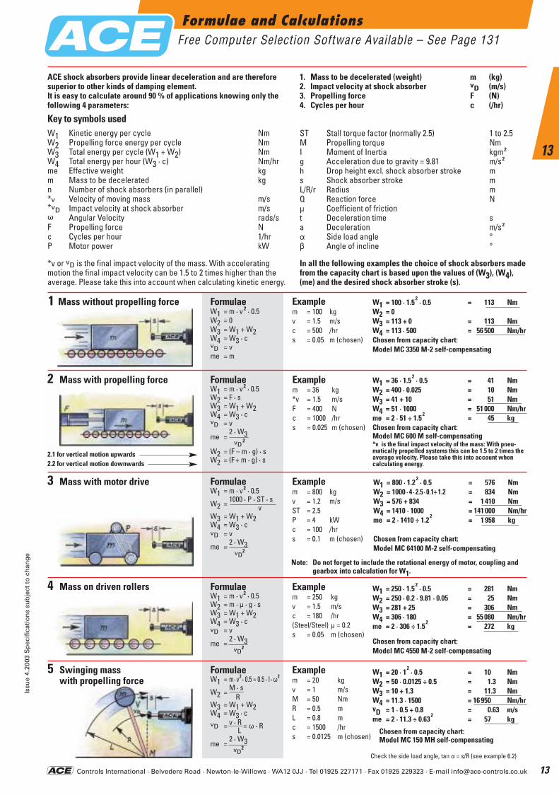
ACE shock absorbers provide linear deceleration and are thereforesuperior to other kinds of damping element.It is easy to calculate around 90 % of applications knowing only thefollowing 4 parameters:
*v or vD is the final impact velocity of the mass. With accelerating motion the final impact velocity can be 1.5 to 2 times higher than the average. Please take this into account when calculating kinetic energy.
In all the following examples the choice of shock absorbers madefrom the capacity chart is based upon the values of (W3), (W4),(me) and the desired shock absorber stroke (s).
Key to symbols usedW1 Kinetic energy per cycle NmW2 Propelling force energy per cycle NmW3 Total energy per cycle (W1 + W2) NmW4 Total energy per hour (W3 · c) Nm/hrme Effective weight kgm Mass to be decelerated kgn Number of shock absorbers (in parallel)*v Velocity of moving mass m/s*vD Impact velocity at shock absorber m/sv Angular Velocity rads/sF Propelling force Nc Cycles per hour 1/hrP Motor power kW
1. Mass to be decelerated (weight) m (kg)2. Impact velocity at shock absorber vD (m/s)3. Propelling force F (N)4. Cycles per hour c (/hr)
ST Stall torque factor (normally 2.5) 1 to 2.5M Propelling torque NmI Moment of Inertia kgm 2
g Acceleration due to gravity = 9.81 m/s 2
h Drop height excl. shock absorber stroke ms Shock absorber stroke mL/R/r Radius mQ Reaction force Nm Coefficient of frictiont Deceleration time sa Deceleration m/s 2
a Side load angle °b Angle of incline °
2.1 for vertical motion upwards2.2 for vertical motion downwards
FormulaeW1 = m · v 2 · 0.5W2 = 0W3 = W1 + W2W4 = W3 · cvD = vme = m
W1 = 100 · 1.52
· 0.5 = 113 NmW2 = 0W3 = 113 + 0 = 113 NmW4 = 113 · 500 = 56 500 Nm/hrChosen from capacity chart:Model MC 3350 M-2 self-compensating
FormulaeW1 = m · v2 · 0.5W2 = F · sW3 = W1 + W2W4 = W3 · cvD = v
me =2 · W3
vD2
W2 = (F – m · g) · sW2 = (F + m · g) · s
W1 = 36 · 1.52
· 0.5 = 41 NmW2 = 400 · 0.025 = 10 NmW3 = 41 + 10 = 51 NmW4 = 51 · 1000 = 51 000 Nm/hrme = 2 · 51 ÷ 1.5
2= 45 kg
Chosen from capacity chart:Model MC 600 M self-compensating*v is the final impact velocity of the mass: With pneu-matically propelled systems this can be 1.5 to 2 times the average velocity. Please take this into account when calculating energy.
FormulaeW1 = m · v2 · 0.5 = 0.5 · I · v2
W2 = M · sR
W3 = W1 + W2W4 = W3 · cvD = v · R = v · R
L
me =2 · W3
vD2
W1 = 20 · 12
· 0.5 = 10 NmW2 = 50 · 0.0125 ÷ 0.5 = 1.3 NmW3 = 10 + 1.3 = 11.3 NmW4 = 11.3 · 1500 = 16 950 Nm/hrvD = 1 · 0.5 ÷ 0.8 = 0.63 m/sme = 2 · 11.3 ÷ 0.63
2= 57 kg
Chosen from capacity chart:Model MC 150 MH self-compensating
FormulaeW1 = m · v2 · 0.5
W2 = 1000 · P · ST · sv
W3 = W1 + W2W4 = W3 · cvD = v
me =2 · W3
vD2
W1 = 800 · 1.22
· 0.5 = 576 NmW2 = 1000 · 4 · 2.5 · 0.1÷ 1.2 = 834 NmW3 = 576 + 834 = 1 410 NmW4 = 1410 · 1000 = 141 000 Nm/hrme = 2 · 1410 ÷ 1.2
2= 1 958 kg
Chosen from capacity chart:Model MC 64100 M-2 self-compensating
Check the side load angle, tan a = s/R (see example 6.2)
Note: Do not forget to include the rotational energy of motor, coupling and gearbox into calculation for W1.
Examplem = 250 kgv = 1.5 m/sc = 180 /hr(Steel/Steel) m = 0.2s = 0.05 m (chosen)
W1 = 250 · 1.52
· 0.5 = 281 NmW2 = 250 · 0.2 · 9.81 · 0.05 = 25 NmW3 = 281 + 25 = 306 NmW4 = 306 · 180 = 55 080 Nm/hrme = 2 · 306 ÷ 1.5
2= 272 kg
Chosen from capacity chart:Model MC 4550 M-2 self-compensating
FormulaeW1 = m · v2 · 0.5W2 = m · m · g · sW3 = W1 + W2W4 = W3 · cvD = v
me =2 · W3
vD2
1 Mass without propelling force
2 Mass with propelling force
3 Mass with motor drive
4 Mass on driven rollers
5 Swinging mass with propelling force
ACE-Kat_2003_UK_008-013 22.09.2003 16:57 Uhr Seite 13
Controls International · Belvedere Road · Newton-le-Willows · WA12 0JJ · Tel 01925 227171 · Fax 01925 229323 · E-mail [email protected]
Formulae and Calculations
Issu
e 4.
2003
Sp
ecif
icat
ion
s su
bje
ct t
o c
han
ge
14
14
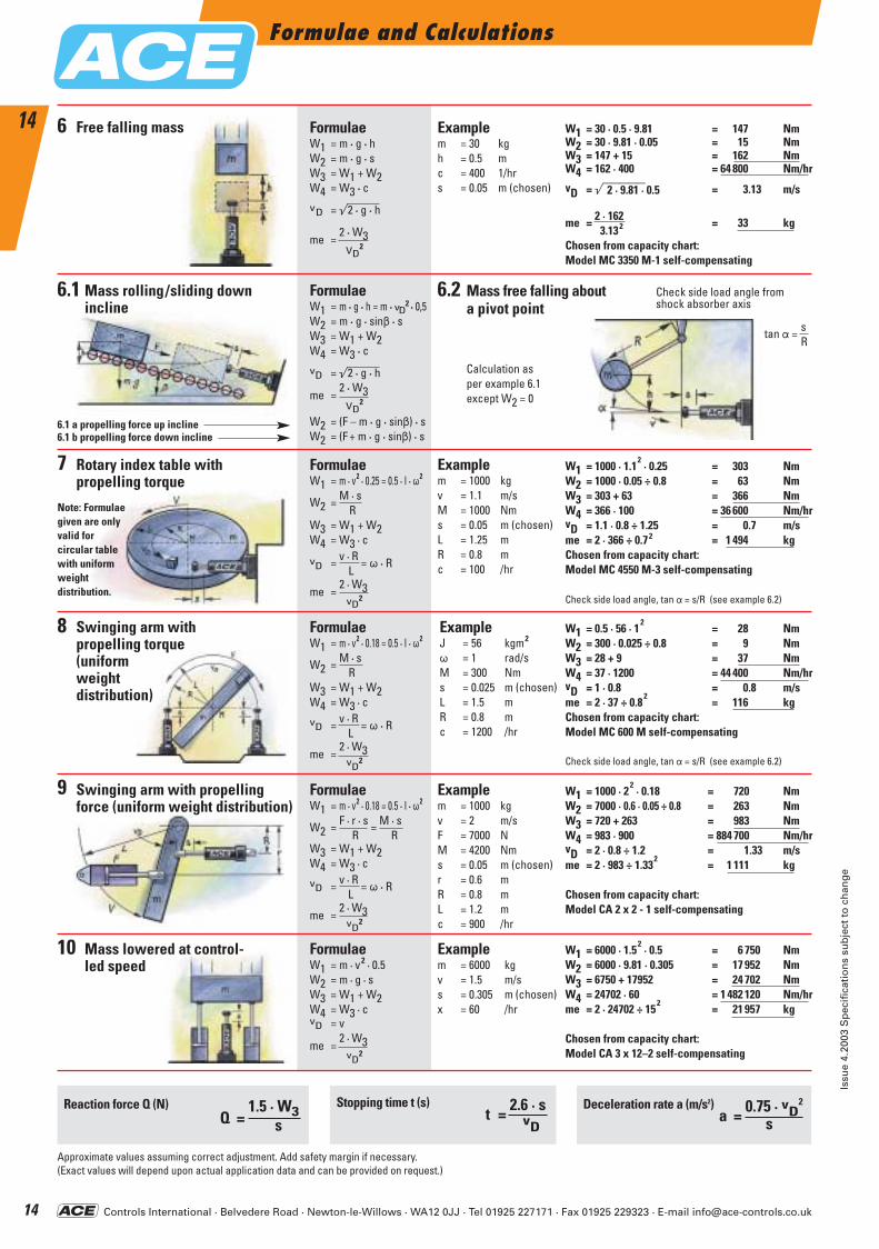
Q =1.5 · W3
s
FormulaeW1 = m · v2 · 0.18 = 0.5 · I · v2
W2 = F · r · s = M · sR R
W3 = W1 + W2W4 = W3 · c
vD = v · R = v · RL
me =2 · W3
vD2
Examplem = 1000 kgv = 2 m/sF = 7000 NM = 4200 Nms = 0.05 m (chosen)r = 0.6 mR = 0.8 mL = 1.2 mc = 900 /hr
W1 = 1000 · 22
· 0.18 = 720 NmW2 = 7000 · 0.6 · 0.05 ÷ 0.8 = 263 NmW3 = 720 + 263 = 983 NmW4 = 983 · 900 = 884 700 Nm/hrvD = 2 · 0.8 ÷ 1.2 = 1.33 m/sme = 2 · 983 ÷ 1.33
2= 1 111 kg
Chosen from capacity chart:Model CA 2 x 2 - 1 self-compensating
FormulaeW1 = m · v2 · 0.5W2 = m · g · sW3 = W1 + W2W4 = W3 · cvD = v
me =2 · W3
vD2
Examplem = 6000 kgv = 1.5 m/ss = 0.305 m (chosen)x = 60 /hr
W1 = 6000 · 1.52
· 0.5 = 6 750 NmW2 = 6000 · 9.81 · 0.305 = 17 952 NmW3 = 6750 + 17952 = 24 702 NmW4 = 24702 · 60 = 1 482 120 Nm/hrme = 2 · 24702 ÷ 15
2= 21 957 kg
Chosen from capacity chart:Model CA 3 x 12–2 self-compensating
FormulaeW1 = m · v2 · 0.18 = 0.5 · I · v2
W2 = M · sR
W3 = W1 + W2W4 = W3 · c
vD = v · R = v · RL
me =2 · W3
vD2
ExampleJ = 56 kgm2
v = 1 rad/sM = 300 Nms = 0.025 m (chosen)L = 1.5 mR = 0.8 mc = 1200 /hr
W1 = 0.5 · 56 · 12
= 28 NmW2 = 300 · 0.025 ÷ 0.8 = 9 NmW3 = 28 + 9 = 37 NmW4 = 37 · 1200 = 44 400 Nm/hrvD = 1 · 0.8 = 0.8 m/sme = 2 · 37 ÷ 0.8
2= 116 kg
Chosen from capacity chart:Model MC 600 M self-compensating
Reaction force Q (N) Deceleration rate a (m/s2)a = 0.75 · vD
2
s
Approximate values assuming correct adjustment. Add safety margin if necessary.(Exact values will depend upon actual application data and can be provided on request.)
FormulaeW1 = m · g · hW2 = m · g · sW3 = W1 + W2W4 = W3 · c
vD = ö2 · g · h
me =2 · W3
VD2
Examplem = 30 kgh = 0.5 mc = 400 1/hrs = 0.05 m (chosen)
W1 = 30 · 0.5 · 9.81 = 147 NmW2 = 30 · 9.81 · 0.05 = 15 NmW3 = 147 + 15 = 162 NmW4 = 162 · 400 = 64 800 Nm/hr
vD = öäääää = 3.13 m/s2 · 9.81 · 0.5
me = 2 · 162 = 33 kg3.132
Chosen from capacity chart:Model MC 3350 M-1 self-compensating
FormulaeW1 = m · g · h = m · vD
2 · 0,5W2 = m · g · sinb · sW3 = W1 + W2W4 = W3 · c
vD = ö2 · g · h
me =2 · W3
VD2
W2 = (F – m · g · sinb) · sW2 = (F + m · g · sinb) · s
FormulaeW1 = m · v2 · 0.25 = 0.5 · I · v2
W2 = M · sR
W3 = W1 + W2W4 = W3 · c
vD = v · R = v · RL
me =2 · W3
vD2
Examplem = 1000 kgv = 1.1 m/sM = 1000 Nms = 0.05 m (chosen)L = 1.25 mR = 0.8 mc = 100 /hr
W1 = 1000 · 1.12
· 0.25 = 303 NmW2 = 1000 · 0.05 ÷ 0.8 = 63 NmW3 = 303 + 63 = 366 NmW4 = 366 · 100 = 36 600 Nm/hrvD = 1.1 · 0.8 ÷ 1.25 = 0.7 m/sme = 2 · 366 ÷ 0.72 = 1 494 kgChosen from capacity chart:Model MC 4550 M-3 self-compensating
Check side load angle, tan a = s/R (see example 6.2)
Check side load angle, tan a = s/R (see example 6.2)
t = 2.6 · svD
Stopping time t (s)
Free falling mass6
6.1 Mass rolling/sliding down incline
7 Rotary index table with propelling torque
8 Swinging arm with propelling torque (uniform weight distribution)
9 Swinging arm with propelling force (uniform weight distribution)
6.2
10 Mass lowered at control-led speed
Mass free falling about Check side load angle froma pivot point shock absorber axis
Calculation as per example 6.1except W2 = 0
tan a = sR
6.1 a propelling force up incline6.1 b propelling force down incline
Note: Formulae given are only valid for circular table with uniformweight distribution.
ACE-Kat_2003_UK_014-019 22.09.2003 16:59 Uhr Seite 14
Controls International · Belvedere Road · Newton-le-Willows · WA12 0JJ · Tel 01925 227171 · Fax 01925 229323 · E-mail [email protected]
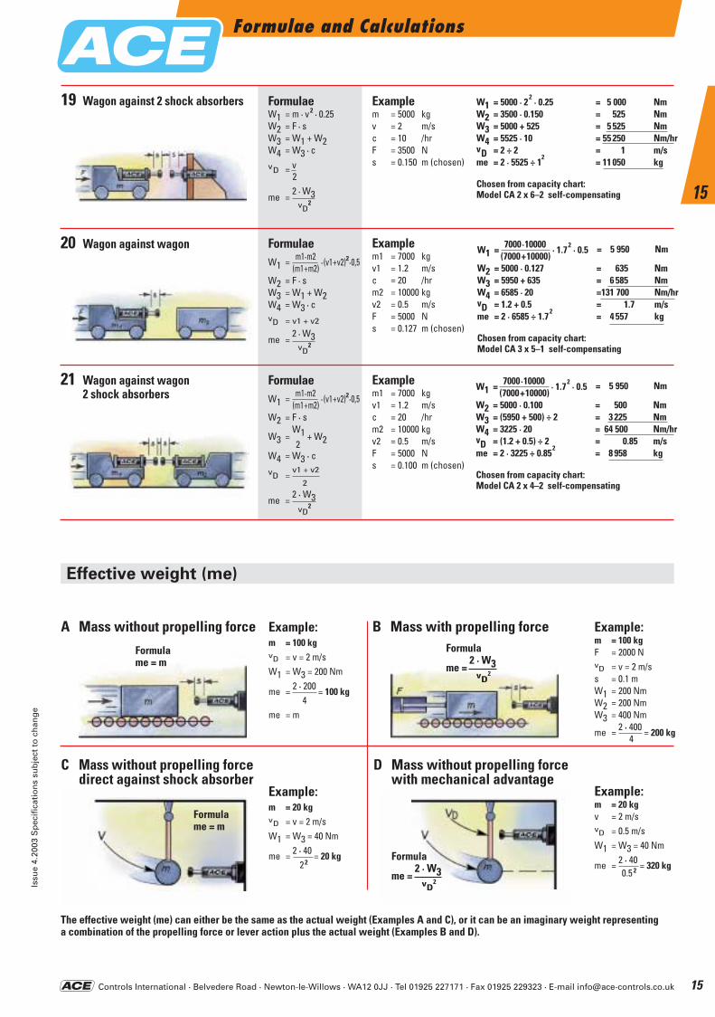
The effective weight (me) can either be the same as the actual weight (Examples A and C), or it can be an imaginary weight representing a combination of the propelling force or lever action plus the actual weight (Examples B and D).
Example:m = 100 kgF = 2000 NvD = v = 2 m/ss = 0.1 mW1 = 200 NmW2 = 200 NmW3 = 400 Nm
me = 2 · 400 = 200 kg4
Example:m = 20 kgv = 2 m/svD = 0.5 m/sW1 = W3 = 40 Nm
me = 2 · 40 = 320 kg0.5 2
Example:m = 20 kgvD = v = 2 m/sW1 = W3 = 40 Nm
me = 2 · 40 = 20 kg22
Formula
me =2 · W3
vD2
Formulame = m
Example:m = 100 kgvD = v = 2 m/sW1 = W3 = 200 Nm
me = 2 · 200 = 100 kg4
me = m
Examplem = 5000 kgv = 2 m/sc = 10 /hrF = 3500 Ns = 0.150 m (chosen)
FormulaeW1 = m1·m2 · (v1+v2)2·0,5
(m1+m2)W2 = F · sW3 = W1 + W2W4 = W3 · cvD = v1 + v2
me =2 · W3
vD2
Examplem1 = 7000 kgv1 = 1.2 m/sc = 20 /hrm2 = 10000 kgv2 = 0.5 m/sF = 5000 Ns = 0.127 m (chosen)
W1 = 7000·10000 · 1.72
· 0.5 = 5 950 Nm(7000+10000)
W2 = 5000 · 0.127 = 635 NmW3 = 5950 + 635 = 6 585 NmW4 = 6585 · 20 =131 700 Nm/hrvD = 1.2 + 0.5 = 1.7 m/sme = 2 · 6585 ÷ 1.7
2= 4 557 kg
Chosen from capacity chart:Model CA 3 x 5–1 self-compensating
FormulaeW1 = m1·m2 · (v1+v2)2·0,5
(m1+m2)W2 = F · s
W3 =W1 + W22
W4 = W3 · c
vD =v1 + v2
2
me =2 · W3
vD2
Examplem1 = 7000 kgv1 = 1.2 m/sc = 20 /hrm2 = 10000 kgv2 = 0.5 m/sF = 5000 Ns = 0.100 m (chosen)
W1 = 7000·10000 · 1.72
· 0.5 = 5 950 Nm(7000+10000)
W2 = 5000 · 0.100 = 500 NmW3 = (5950 + 500) ÷ 2 = 3 225 NmW4 = 3225 · 20 = 64 500 Nm/hrvD = (1.2 + 0.5) ÷ 2 = 0.85 m/sme = 2 · 3225 ÷ 0.85
2= 8 958 kg
Chosen from capacity chart:Model CA 2 x 4–2 self-compensating
Effective weight (me)
W1 = 5000 · 22
· 0.25 = 5 000 NmW2 = 3500 · 0.150 = 525 NmW3 = 5000 + 525 = 5 525 NmW4 = 5525 · 10 = 55 250 Nm/hrvD = 2 ÷ 2 = 1 m/sme = 2 · 5525 ÷ 1
2= 11 050 kg
Chosen from capacity chart:Model CA 2 x 6–2 self-compensating
Formulame = m
FormulaeW1 = m · v2 · 0.25W2 = F · sW3 = W1 + W2W4 = W3 · c
vD = v 2
me =2 · W3
vD2
Formula
me =2 · W3
vD2
19 Wagon against 2 shock absorbers
Wagon against wagon20
Wagon against wagon2 shock absorbers
21
A Mass without propelling force
C Mass without propelling forcedirect against shock absorber
D Mass without propelling forcewith mechanical advantage
B Mass with propelling force
Formulae and CalculationsIs
sue
4.20
03 S
pec
ific
atio
ns
sub
ject
to
ch
ang
e
15
15
ACE-Kat_2003_UK_014-019 22.09.2003 16:59 Uhr Seite 15
Controls International · Belvedere Road · Newton-le-Willows · WA12 0JJ · Tel 01925 227171 · Fax 01925 229323 · E-mail [email protected]
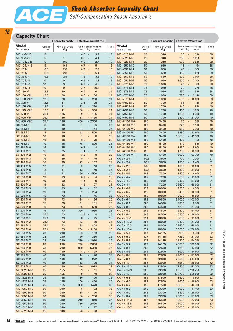
Shock Absorber Capacity ChartSelf-Compensating Shock Absorbers
Issu
e 4.
2003
Sp
ecif
icat
ion
s su
bje
ct t
o c
han
ge
16
16Capacity Chart
MC 9 M-1-B 5 1 0.6 - 3.2 19MC 9 M-2-B 5 1 0.8 - 4.1 19MC 10 ML-B 5 0.5 0.3 - 2.7 19MC 10 MH-B 5 0.8 0.7 - 5 19MC 25 ML 6.6 2.8 0.7 - 2.2 19MC 25 M 6.6 2.8 1.8 - 5.4 19MC 25 MH 6.6 2.8 4.6 - 13.6 19MC 75 M-1 10 9 0.3 - 1.1 19MC 75 M-2 10 9 0.9 - 4.8 19MC 75 M-3 10 9 2.7 - 36.2 19MC 150 M 12.5 20 0.9 - 10 21MC 150 MH 12.5 20 8.6 - 86 21MC 150 MH2 12.5 20 70 - 200 21MC 225 M 12.5 41 2.3 - 25 21MC 225 MH 12.5 41 23 - 230 21MC 225 MH2 12.5 41 180 - 910 21MC 600 M 25.4 136 9 - 136 21MC 600 MH 25.4 136 113 - 1 130 21MC 600 MH2 25.4 136 400 - 2 300 21SC 25 M-5 8 10 1 - 5 25SC 25 M-6 8 10 4 - 44 25SC 25 M-7 8 10 42 - 500 25SC 75 M-5 10 16 1 - 8 25SC 75 M-6 10 16 6.8 - 78 25SC 75 M-7 10 16 75 - 800 25SC 190 M-0 16 25 0.7 - 4 23SC 190 M-1 16 25 1.4 - 7 23SC 190 M-2 16 25 3.6 - 18 23SC 190 M-3 16 25 9 - 45 23SC 190 M-4 16 25 23 - 102 23SC 190 M-5 12 31 2 - 16 25SC 190 M-6 12 31 13 - 140 25SC 190 M-7 12 31 136 - 1 550 25SC 300 M-0 19 33 0.7 - 4 23SC 300 M-1 19 33 1.4 - 8 23SC 300 M-2 19 33 4.5 - 27 23SC 300 M-3 19 33 14 - 82 23SC 300 M-4 19 33 32 - 204 23SC 300 M-5 15 73 11 - 45 25SC 300 M-6 15 73 34 - 136 25SC 300 M-7 15 73 91 - 181 25SC 300 M-8 15 73 135 - 680 25SC 300 M-9 15 73 320 - 1 950 25SC 650 M-0 25.4 73 2.3 - 14 23SC 650 M-1 25.4 73 8 - 45 23SC 650 M-2 25.4 73 23 - 136 23SC 650 M-3 25.4 73 68 - 408 23SC 650 M-4 25.4 73 204 - 1180 23SC 650 M-5 23 210 23 - 113 25SC 650 M-6 23 210 90 - 360 25SC 650 M-7 23 210 320 - 1 090 25SC 650 M-8 23 210 770 - 2 630 25SC 650 M-9 23 210 1 800 - 6 350 25SC 925 M-0 40 110 4.5 - 29 23SC 925 M-1 40 110 14 - 90 23SC 925 M-2 40 110 40 - 272 23SC 925 M-3 40 110 113 - 726 23SC 925 M-4 40 110 340 - 2 088 23MC 3325 M-0 25 155 3 - 11 36MC 3325 M-1 25 155 9 - 40 36MC 3325 M-2 25 155 30 - 120 36MC 3325 M-3 25 155 100 - 420 36MC 3325 M-4 25 155 350 - 1420 36MC 3350 M-0 50 310 5 - 22 36MC 3350 M-1 50 310 18 - 70 36MC 3350 M-2 50 310 60 - 250 36MC 3350 M-3 50 310 210 - 840 36MC 3350 M-4 50 310 710 - 2 830 36MC 4525 M-0 25 340 7 - 27 38MC 4525 M-1 25 340 20 - 90 38
MC 4525 M-2 25 340 80 - 310 38MC 4525 M-3 25 340 260 - 1 050 38MC 4525 M-4 25 340 890 - 3 540 38MC 4550 M-0 50 680 13 - 54 38MC 4550 M-1 50 680 45 - 180 38MC 4550 M-2 50 680 150 - 620 38MC 4550 M-3 50 680 520 - 2 090 38MC 4550 M-4 50 680 1 800 - 7 100 38MC 4575 M-0 75 1 020 20 - 80 38MC 4575 M-1 75 1 020 70 - 270 38MC 4575 M-2 75 1 020 230 - 930 38MC 4575 M-3 75 1 020 790 - 3 140 38MC 4575 M-4 75 1 020 2 650 - 10 600 38MC 6450 M-0 50 1 700 35 - 140 40MC 6450 M-1 50 1 700 140 - 540 40MC 6450 M-2 50 1 700 460 - 1 850 40MC 6450 M-3 50 1 700 1 600 - 6 300 40MC 6450 M-4 50 1 700 5 300 - 21 200 40MC 64100 M-0 100 3 400 70 - 280 40MC 64100 M-1 100 3 400 270 - 1 100 40MC 64100 M-2 100 3 400 930 - 3 700 40MC 64100 M-3 100 3 400 3 150 - 12 600 40MC 64100 M-4 100 3 400 10 600 - 42 500 40MC 64150 M-0 150 5100 100 - 460 40MC 64150 M-1 150 5100 410 - 1 640 40MC 64150 M-2 150 5100 1 390 - 5 600 40MC 64150 M-3 150 5100 4 700 - 18 800 40MC 64150 M-4 150 5100 16 000 - 63 700 40CA 2 x 2-1 50.8 3 600 700 - 2 200 51CA 2 x 2-2 50.8 3 600 1 800 - 5 400 51CA 2 x 2-3 50.8 3 600 4 500 - 13 600 51CA 2 x 2-4 50.8 3 600 11 300 - 34 000 51CA 2 x 4-1 102 7 200 1 400 - 4 400 51CA 2 x 4-2 102 7 200 3 600 - 11 000 51CA 2 x 4-3 102 7 200 9 100 - 27 200 51CA 2 x 4-4 102 7 200 22 600 - 68 000 51CA 2 x 6-1 152 10 800 2 200 - 6 500 51CA 2 x 6-2 152 10 800 5 400 - 16 300 51CA 2 x 6-3 152 10 800 13 600 - 40 800 51CA 2 x 6-4 152 10 800 34 000 - 102 000 51CA 2 x 8-1 203 14 500 2 900 - 8 700 51CA 2 x 8-2 203 14 500 7 200 - 21 700 51CA 2 x 8-3 203 14 500 18 100 - 54 400 51CA 2 x 8-4 203 14 500 45 300 - 136 000 51CA 2 x 10⁻¹ 254 18 000 3 600 - 11 000 51CA 2 x 10⁻² 254 18 000 9 100 - 27 200 51CA 2 x 10⁻³ 254 18 000 22 600 - 68 000 51CA 2 x 10⁻⁴ 254 18 000 56 600 - 170 000 51CA 3 x 5-1 127 14 125 2 900 - 8 700 52CA 3 x 5-2 127 14 125 7 250 - 21 700 52CA 3 x 5-3 127 14 125 18 100 - 54 350 52CA 3 x 5-4 127 14 125 45 300 - 135 900 52CA 3 x 8-1 203 22 600 4 650 - 13 900 52CA 3 x 8-2 203 22 600 11 600 - 34 800 52CA 3 x 8-3 203 22 600 29 000 - 87 000 52CA 3 x 8-4 203 22 600 72 500 - 217 000 52CA 3 x 12-1 305 33 900 6 950 - 20 900 52CA 3 x 12-2 305 33 900 17 400 - 52 200 52CA 3 x 12-3 305 33 900 43 500 - 130 450 52CA 3 x 12-4 305 33 900 108 700 - 326 000 52CA 4 x 6-3 152 47 500 3 500 - 8 600 53CA 4 x 6-5 152 47 500 8 600 - 18 600 53CA 4 x 6-7 152 47 500 18 600 - 42 700 53CA 4 x 8-3 203 63 300 5 000 - 11 400 53CA 4 x 8-5 203 63 300 11 400 - 25 000 53CA 4 x 8-7 203 63 300 25 000 - 57 000 53CA 4 x 16-3 406 126 500 10 000 - 23 000 53CA 4 x 16-5 406 126 500 23 000 - 50 000 53CA 4 x 16-7 406 126 500 50 000 - 115 000 53
Nm per Cycle W3
Strokemm
ModelPart number
Self-Compensatingmin kg max
Page
Effective Weight meEnergy Capacity
Nm per Cycle W3
Strokemm
ModelPart number
Self-Compensatingmin kg max
Page
Effective Weight meEnergy Capacity
ACE-Kat_2003_UK_014-019 22.09.2003 16:59 Uhr Seite 16
Controls International · Belvedere Road · Newton-le-Willows · WA12 0JJ · Tel 01925 227171 · Fax 01925 229323 · E-mail [email protected]
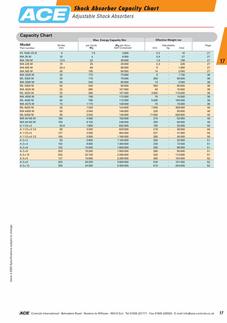
Shock Absorber Capacity ChartAdjustable Shock Absorbers
Issu
e 4.
2003
Sp
ecif
icat
ion
s su
bje
ct t
o c
han
ge
17
17
Capacity Chart
FA 1008 VD-B 8 1.8 3 600 0.2 - 10 27MA 35 M 10 4 6 000 5.9 - 57 27MA 150 M 12.5 22 35 000 1.0 - 109 27MA 225 M 19 25 45 000 2.3 - 226 27MA 600 M 25.4 68 68 000 9 - 1 360 27MA 900 M 40 100 90 000 14 - 2 040 27MA 3325 M 25 170 75 000 9 - 1 730 36ML 3325 M 25 170 75 000 300 - 50 000 36MA 3350 M 50 340 85 000 13 - 2 500 36ML 3350 M 50 340 85 000 500 - 80 000 36MA 4525 M 25 390 107 000 40 - 10 000 38ML 4525 M 25 390 107 000 3 000 - 110 000 38MA 4550 M 50 780 112 000 70 - 14 500 38ML 4550 M 50 780 112 000 5 000 - 180 000 38MA 4575 M 75 1 170 146 000 70 - 15 000 38ML 6425 M 25 1 020 124 000 7 000 - 300 000 40MA 6450 M 50 2 040 146 000 220 - 50 000 40ML 6450 M 50 2 040 146 000 11 000 - 500 000 40MA 64100 M 100 4 080 192 000 270 - 52 000 40MA 64150 M 150 6 120 248 000 330 - 80 000 40A 11/2 x 2 50.8 1800 632 000 195 - 32 000 50A 11/2 x 3 1/2 89 3 200 633 000 218 - 36 000 50A 11/2 x 5 127 4 500 904 000 227 - 41 000 50A 11/2 x 6 1/2 165 5 900 1 180 000 308 - 45 000 50A 2 x 2 50 3 600 1 100 000 250 - 32 000 51A 2 x 4 102 9 000 1 350 000 230 - 72 500 51A 2 x 6 152 13 500 1 600 000 260 - 86 000 51A 2 x 8 203 19 200 1 900 000 260 - 90 000 51A 2 x 10 254 23 700 2 200 000 320 - 113 000 51A 3 x 5 127 15 800 2 260 000 480 - 154 000 52A 3 x 8 203 28 200 3 600 000 540 - 181 500 52A 3 x 12 305 44 000 5 400 000 610 - 204 000 52
Max. Energy Capacity Nm
W4 per HourSelf Contained
per CycleW3
Strokemm
ModelPart number
Adjustablemin kg max
Page
Effective Weight me
ACE-Kat_2003_UK_014-019 22.09.2003 16:59 Uhr Seite 17
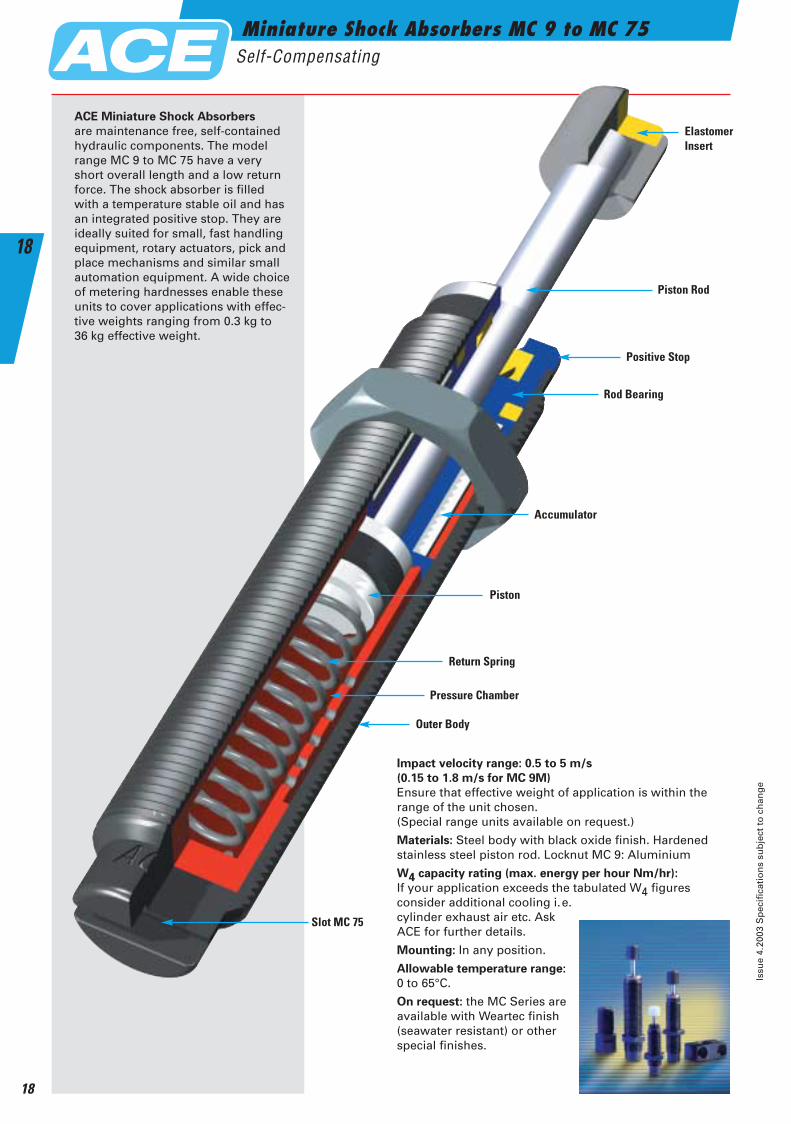
Miniature Shock Absorbers MC 9 to MC 75Self-Compensating
Issu
e 4.
2003
Sp
ecif
icat
ion
s su
bje
ct t
o c
han
ge
18
18
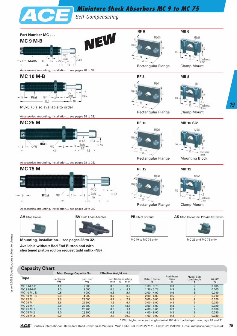
Impact velocity range: 0.5 to 5 m/s
(0.15 to 1.8 m/s for MC 9M)
Ensure that effective weight of application is within therange of the unit chosen. (Special range units available on request.)
Materials: Steel body with black oxide finish. Hardenedstainless steel piston rod. Locknut MC 9: Aluminium
W4 capacity rating (max. energy per hour Nm/hr):
If your application exceeds the tabulated W4 figures consider additional cooling i.e. cylinder exhaust air etc. Ask ACE for further details.
Mounting: In any position.
Allowable temperature range:
0 to 65°C.
On request: the MC Series are available with Weartec finish (seawater resistant) or other special finishes.
Elastomer Insert
Piston Rod
Positive Stop
Rod Bearing
Accumulator
Piston
Pressure Chamber
Outer Body
Slot MC 75
Return Spring
ACE Miniature Shock Absorbers
are maintenance free, self-contained hydraulic components. The model range MC 9 to MC 75 have a very short overall length and a low return force. The shock absorber is filled with a temperature stable oil and has an integrated positive stop. They are ideally suited for small, fast handling equipment, rotary actuators, pick and place mechanisms and similar small automation equipment. A wide choice of metering hardnesses enable these units to cover applications with effec-tive weights ranging from 0.3 kg to 36 kg effective weight.
ACE-Kat_2003_UK_014-019 22.09.2003 17:00 Uhr Seite 18
Controls International · Belvedere Road · Newton-le-Willows · WA12 0JJ · Tel 01925 227171 · Fax 01925 229323 · E-mail [email protected]
Miniature Shock Absorbers MC 9 to MC 75Self-Compensating
Issu
e 4.
2003
Sp
ecif
icat
ion
s su
bje
ct t
o c
han
ge
19
19
Available without Rod End Button and with
shortened piston rod on request (add suffix -NB)
Part Number MC . . .
5 3 Stroke∅2 2
AF 115
28,5
∅6,4M8x110
2
5 Stroke
∅ 3,2 3
AF 1410
52
∅ 7,6M12x1
18
4 3
5 Stroke∅ 3,2 3
AF 13 6,643
∅ 7,6M10x1
14,63 5AF 5
AF11Stroke
AF13AF5Stroke
AF14 Stroke
M8x0,75 also available to orderRectangular Flange Clamp Mount
Accessories, mounting, installation… see pages 28 to 32.
Rectangular Flange Clamp MountAccessories, mounting, installation… see pages 28 to 32. .
Rectangular Flange Mounting BlockAccessories, mounting, installation… see pages 28 to 32.
Rectangular Flange Clamp MountAccessories, mounting, installation… see pages 28 to 32.
AH Stop Collar BV Side Load Adaptor PB Steel Shroud AS Stop Collar incl Proximity Switch
Mounting, installation… see pages 28 to 32.
2,5 2,5Hub
2SW 8
526
M6x0,510
2,7 ∅4,8
∅2
NEW
Capacity ChartEffective Weight meMax. Energy Capacity Nm
per Hour W4
per Cycle W3
Return ForceN
Rod ResetTime
s
*Max. SideLoad Angle
°Weight
kg
Type Self-Compensatingmin kg max
MC 9 M-1-B 1.0 2 000 0.6 - 3.2 1.38 - 3.78 0.3 2 0.005MC 9 M-2-B 1.0 2 000 0.8 - 4.1 1.38 - 3.78 0.3 2 0.005MC 10 ML-B 0.5 4 000 0.3 - 2.7 2.00 - 4.00 0.6 3 0.010MC 10 MH-B 0.8 4 000 0.7 - 5.0 2.00 - 4.00 0.6 3 0.010MC 25 ML 2.8 22 500 0.7 - 2.2 3.00 - 6.00 0.3 2 0.020MC 25 M 2.8 22 500 1.8 - 5.4 3.00 - 6.00 0.3 2 0.020MC 25 MH 2.8 22 500 4.6 - 13.6 3.00 - 6.00 0.3 2 0.020MC 75 M-1 9.0 28 200 0.3 - 1.1 4.00 - 9.00 0.3 2 0.030MC 75 M-2 9.0 28 200 0.9 - 4.8 4.00 - 9.00 0.3 2 0.030MC 75 M-3 9.0 28 200 2.7 - 36.2 4.00 - 9.00 0.3 2 0.030
* With higher side load angles install BV side load adaptor see page 28 and 31.
MC 10 M-B RF 8 MB 8
MC 25 M RF 10 MB 10 SC2
MC 75 M RF 12 MB 12
MC 25 and MC 75 only
AF8Stroke 20
10
3
Breite8 mm
M6x0,5
M3
12
20
10
5M6x0,5
14
M3x8MC 9 M-B
MB 6 RF 6
Thickness8 mm
25
12
3,5Breite10 mm
M8x1
M4
16
25
14
6M8x1
18
M4x10
Thickness10 mm
28
14
6M10x1
20
M4x10
32
16
4,5Breite12 mm
M12x1
M5
20
32
20
6M12x1
24
M5x12
Thickness12 mm
MC 10 to MC 75 only
25
14
3,5Breite10 mm
M10x1
M4
16Thickness10 mm
ACE-Kat_2003_UK_014-019 22.09.2003 17:00 Uhr Seite 19
Miniature Shock Absorber MC 150 to MC 600Self-Compensating
Issu
e 4.
2003
Sp
ecif
icat
ion
s su
bje
ct t
o c
han
ge
20
20
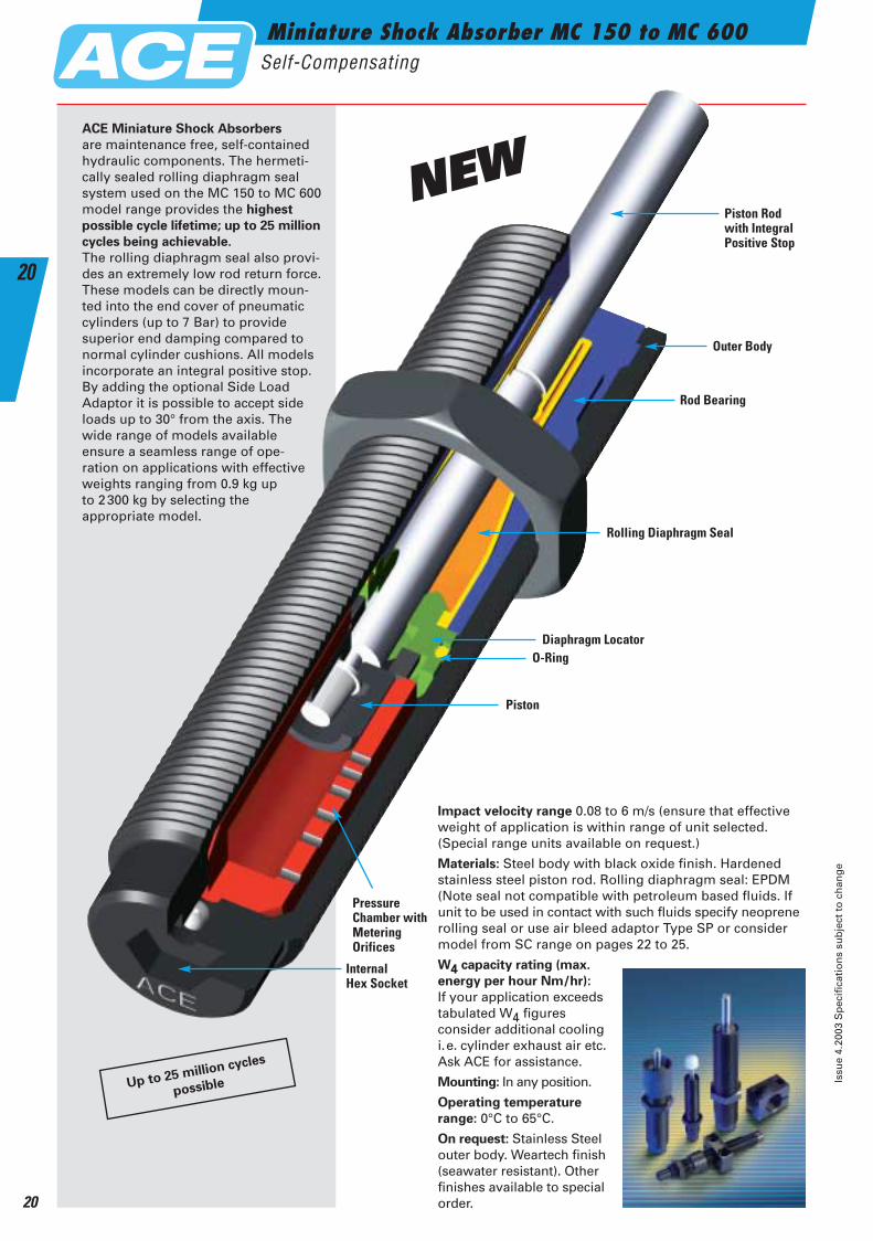
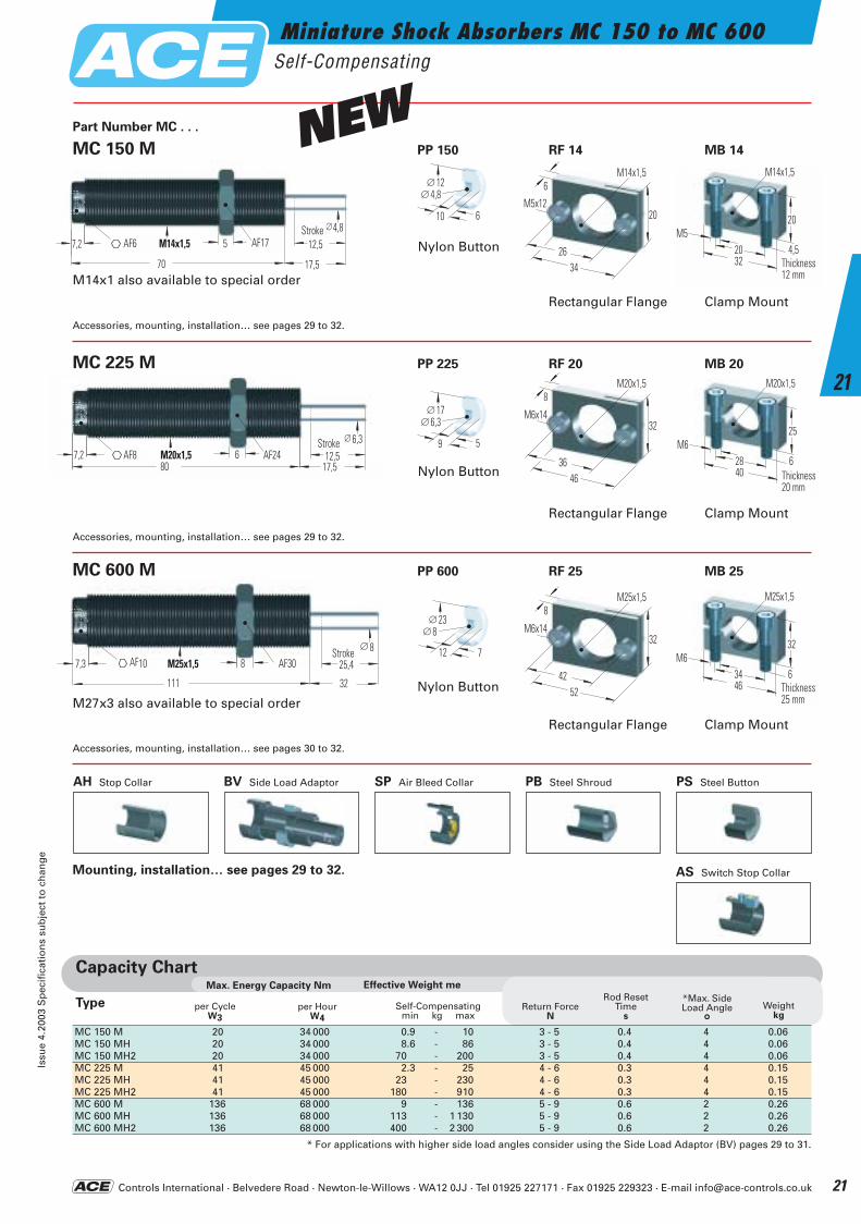
Impact velocity range 0.08 to 6 m/s (ensure that effectiveweight of application is within range of unit selected.(Special range units available on request.)
Materials: Steel body with black oxide finish. Hardenedstainless steel piston rod. Rolling diaphragm seal: EPDM(Note seal not compatible with petroleum based fluids. Ifunit to be used in contact with such fluids specify neoprenerolling seal or use air bleed adaptor Type SP or considermodel from SC range on pages 22 to 25.
W4 capacity rating (max.
energy per hour Nm/hr):
If your application exceeds tabulated W4 figures consider additional coolingi.e. cylinder exhaust air etc.Ask ACE for assistance.
Mounting: In any position.
Operating temperature
range: 0°C to 65°C.
On request: Stainless Steelouter body. Weartech finish(seawater resistant). Other finishes available to specialorder.
ACE Miniature Shock Absorbers
are maintenance free, self-containedhydraulic components. The hermeti-cally sealed rolling diaphragm seal system used on the MC 150 to MC 600model range provides the highest
possible cycle lifetime; up to 25 million
cycles being achievable.
The rolling diaphragm seal also provi-des an extremely low rod return force.These models can be directly moun-ted into the end cover of pneumaticcylinders (up to 7 Bar) to providesuperior end damping compared tonormal cylinder cushions. All modelsincorporate an integral positive stop.By adding the optional Side LoadAdaptor it is possible to accept sideloads up to 30° from the axis. Thewide range of models available ensure a seamless range of ope-ration on applications with effective weights ranging from 0.9 kg up to 2300 kg by selecting the appropriate model.
Piston Rod with Integral Positive Stop
Outer Body
Rod Bearing
Rolling Diaphragm Seal
Diaphragm Locator
InternalHex Socket
O-Ring
Piston
PressureChamber withMeteringOrifices
NEW
Up to 25 million cycles
possible
ACE-Kat_2003_UK_020-025 22.09.2003 16:13 Uhr Seite 20
Miniature Shock Absorbers MC 150 to MC 600Self-Compensating
Issu
e 4.
2003
Sp
ecif
icat
ion
s su
bje
ct t
o c
han
ge
21
21
M25x1,57,3 8 AF30 25,4Stroke
∅ 8
111 32
AF10
M20x1,57,280
AF24 12,517,5
Stroke∅6,3
6AF8
M14x1,57,2 5 AF17 12,5Stroke∅4,8
70 17,5
AF6
MC 150 M PP 150 RF 14 MB 14
MC 600 M PP 600 RF 25 MB 25
Part Number MC . . .
Capacity ChartEffective Weight meMax. Energy Capacity Nm
per HourW4
per Cycle W3
Return ForceN
Rod ResetTime
s
*Max. SideLoad Angle
°Weight
kg
Type Self-Compensatingmin kg max
MC 150 M 20 34 000 0.9 - 10 3 - 5 0.4 4 0.06MC 150 MH 20 34 000 8.6 - 86 3 - 5 0.4 4 0.06MC 150 MH2 20 34 000 70 - 200 3 - 5 0.4 4 0.06MC 225 M 41 45 000 2.3 - 25 4 - 6 0.3 4 0.15MC 225 MH 41 45 000 23 - 230 4 - 6 0.3 4 0.15MC 225 MH2 41 45 000 180 - 910 4 - 6 0.3 4 0.15MC 600 M 136 68 000 9 - 136 5 - 9 0.6 2 0.26MC 600 MH 136 68 000 113 - 1 130 5 - 9 0.6 2 0.26MC 600 MH2 136 68 000 400 - 2 300 5 - 9 0.6 2 0.26
* For applications with higher side load angles consider using the Side Load Adaptor (BV) pages 29 to 31.
Rectangular Flange Clamp Mount
Accessories, mounting, installation… see pages 29 to 32.
Rectangular Flange Clamp Mount
Accessories, mounting, installation… see pages 29 to 32.
Rectangular Flange Clamp Mount
Accessories, mounting, installation… see pages 30 to 32.
MC 225 M PP 225 RF 20 MB 20
M27x3 also available to special order
M14x1 also available to special order
StrokeAF17AF6
AF24AF8Stroke
StrokeAF30AF10
BV Side Load Adaptor PB Steel ShroudAH Stop Collar SP Air Bleed Collar PS Steel Button
AS Switch Stop CollarMounting, installation… see pages 29 to 32.
34
20
6M14x1,5
26
M5x12
46
32
8M20x1,5
36
M6x14
52
32
8M25x1,5
42
M6x14
32
20
4,5Breite12 mm
M14x1,5
M520
40
25
6Breite20 mm
M20x1,5
M628
Thickness12 mm
Thickness20 mm
46
32
6Breite25 mm
M25x1,5
M634
Thickness25 mm
Nylon Button
12∅
610
4,8∅
Nylon Button
17∅
59
6,3∅
Nylon Button
23∅
712
8∅
NEW
Controls International · Belvedere Road · Newton-le-Willows · WA12 0JJ · Tel 01925 227171 · Fax 01925 229323 · E-mail [email protected]
ACE-Kat_2003_UK_020-025 22.09.2003 16:13 Uhr Seite 21
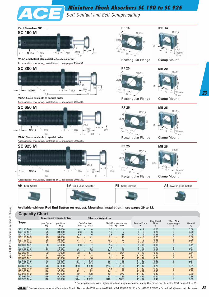
Miniature Shock Absorbers SC 190 to SC 925Soft-Contact and Self-Compensating
Issu
e 4.
2003
Sp
ecif
icat
ion
s su
bje
ct t
o c
han
ge
22
22
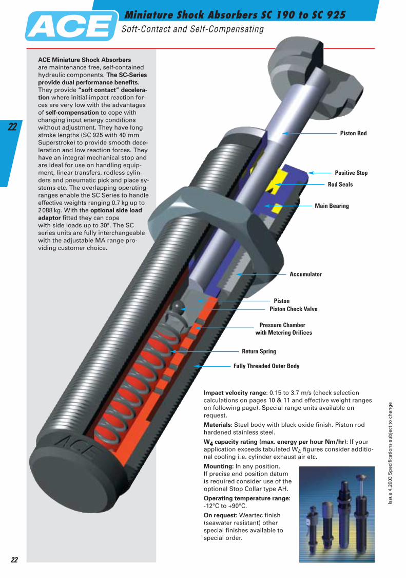
Impact velocity range: 0.15 to 3.7 m/s (check selection calculations on pages 10 & 11 and effective weight rangeson following page). Special range units available on request.
Materials: Steel body with black oxide finish. Piston rodhardened stainless steel.
W4 capacity rating (max. energy per hour Nm/hr): If yourapplication exceeds tabulated W4 figures consider additio-nal cooling i.e. cylinder exhaust air etc.
Mounting: In any position. If precise end position datum is required consider use of theoptional Stop Collar type AH.
Operating temperature range:
-12°C to +90°C.
On request: Weartec finish (seawater resistant) other special finishes available tospecial order.
Piston Rod
Positive Stop
Rod Seals
Main Bearing
Accumulator
Piston
Fully Threaded Outer Body
Pressure Chamber with Metering Orifices
Return Spring
Piston Check Valve
ACE Miniature Shock Absorbers
are maintenance free, self-containedhydraulic components. The SC-Series
provide dual performance benefits.
They provide “soft contact” decelera-
tion where initial impact reaction for-ces are very low with the advantagesof self-compensation to cope withchanging input energy conditions without adjustment. They have longstroke lengths (SC 925 with 40 mmSuperstroke) to provide smooth dece-leration and low reaction forces. Theyhave an integral mechanical stop andare ideal for use on handling equip-ment, linear transfers, rodless cylin-ders and pneumatic pick and place sy-stems etc. The overlapping operatingranges enable the SC Series to handleeffective weights ranging 0.7 kg up to2088 kg. With the optional side load
adaptor fitted they can cope with side loads up to 30°. The SC series units are fully interchangeablewith the adjustable MA range pro-viding customer choice.
ACE-Kat_2003_UK_020-025 22.09.2003 16:13 Uhr Seite 22
32
20
4,5Breite12 mm
M14x1,5
M520
Thickness12 mm
Miniature Shock Absorbers SC 190 to SC 925Soft-Contact and Self-Compensating
Issu
e 4.
2003
Sp
ecif
icat
ion
s su
bje
ct t
o c
han
ge
23
23
∅ 44,6
∅12M14x1,57 AF12 5 AF17 16Hub
87,7 27
∅ 4,84,6
∅ 17M20x1,57 AF18 6
87,4
AF24 1930
Hub
∅ 6,34,6
∅ 23M25x1,57 AF23 8106,6
AF30 25,436,4
Hub
∅ 6,34,6
∅ 23M25x1,57 AF23 8
138
AF30 4051
Hub
Available without Rod End Button on request. Mounting, installation… see pages 29 to 32.
Capacity ChartMax. Energy Capacity Nm Effective Weight me
per Hour W4
per Cycle W3
Return ForceN
Rod ResetTime
s
*Max. SideLoad Angle
°Weight
kg
Type Soft-Contactmin kg max
Self-Compensatingmin kg max
SC 190 M-0 25 34 000 --- - --- 0.7 - 4 4 - 9 0.25 5 0.08SC 190 M-1 25 34 000 2.3 - 6 1.4 - 7 4 - 9 0.25 5 0.08SC 190 M-2 25 34 000 5.5 - 16 3.6 - 18 4 - 9 0.25 5 0.08SC 190 M-3 25 34 000 14 - 41 9 - 45 4 - 9 0.25 5 0.08SC 190 M-4 25 34 000 34 - 91 23 - 102 4 - 9 0.25 5 0.08SC 300 M-0 33 45 000 --- - --- 0.7 - 4 5 - 10 0.10 5 0.11SC 300 M-1 33 45 000 2.3 - 7 1.4 - 8 5 - 10 0.10 5 0.11SC 300 M-2 33 45 000 7 - 23 4.5 - 27 5 - 10 0.10 5 0.11SC 300 M-3 33 45 000 23 - 68 14 - 82 5 - 10 0.10 5 0.11SC 300 M-4 33 45 000 68 - 181 32 - 204 5 - 10 0.10 5 0.11SC 650 M-0 73 68 000 --- - --- 2.3 - 14 11 - 32 0.20 5 0.31SC 650 M-1 73 68 000 11 - 36 8 - 45 11 - 32 0.20 5 0.31SC 650 M-2 73 68 000 34 - 113 23 - 136 11 - 32 0.20 5 0.31SC 650 M-3 73 68 000 109 - 363 68 - 408 11 - 32 0.20 5 0.31SC 650 M-4 73 68 000 363 - 1 089 204 - 1 180 11 - 32 0.20 5 0.31SC 925 M-0 110 90 000 8 - 25 4.5 - 29 11 - 32 0.40 5 0.39SC 925 M-1 110 90 000 22 - 72 14 - 90 11 - 32 0.40 5 0.39SC 925 M-2 110 90 000 59 - 208 40 - 272 11 - 32 0.40 5 0.39SC 925 M-3 110 90 000 181 - 612 113 - 726 11 - 32 0.40 5 0.39SC 925 M-4 110 90 000 544 - 1 952 340 - 2 088 11 - 32 0.40 5 0.39
* For applications with higher side load angles consider using the Side Load Adaptor (BV) pages 29 to 31.
AF12 StrokeAF17
Stroke
Stroke
Stroke
AF18 AF24
AF23 AF30
AF23 AF30
SC 190 M
M26x1,5 also available to special order
Part Number SC . . . MB 14
SC 300 M MB 20
SC 650 M MB 25
Rectangular Flange Clamp MountAccessories, mounting, installation… see pages 30 to 32.
Rectangular Flange Clamp MountAccessories, mounting, installation… see pages 30 to 32.
Rectangular Flange Clamp MountAccessories, mounting, installation… see pages 29 to 32.
Rectangular Flange Clamp MountAccessories, mounting, installation… see pages 29 to 32.
M14x1 and M16x1 also available to special order
M22x1,5 also available to special order
AH Stop Collar BV Side Load Adaptor PB Steel Shroud AS Switch Stop Collar
SC 925 M MB 25
40
25
6Breite20 mm
M20x1,5
M628
Thickness20 mm
46
32
6Breite25 mm
M25x1,5
M634
Thickness25 mm
46
32
6Breite25 mm
M25x1,5
M634
Thickness25 mm52
32
8M25x1,5
42
M6x14
RF 25
52
32
8M25x1,5
42
M6x14
RF 25
34
20
6M14x1,5
26
M5x12
46
32
8M20x1,5
36
M6x14
RF 14
RF 20
Controls International · Belvedere Road · Newton-le-Willows · WA12 0JJ · Tel 01925 227171 · Fax 01925 229323 · E-mail [email protected]
ACE-Kat_2003_UK_020-025 22.09.2003 16:14 Uhr Seite 23
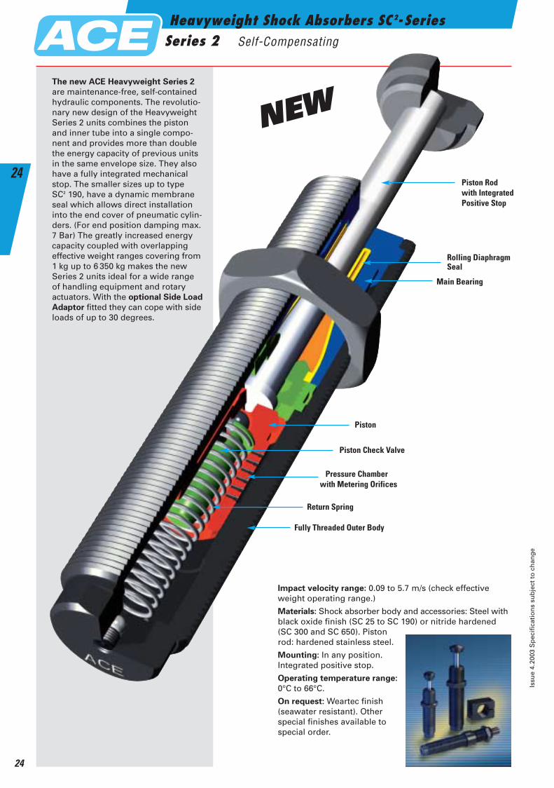
Heavyweight Shock Absorbers SC2- SeriesSeries 2 Self-Compensating
Issu
e 4.
2003
Sp
ecif
icat
ion
s su
bje
ct t
o c
han
ge
24
24
Impact velocity range: 0.09 to 5.7 m/s (check effective weight operating range.)
Materials: Shock absorber body and accessories: Steel withblack oxide finish (SC 25 to SC 190) or nitride hardened(SC 300 and SC 650). Pistonrod: hardened stainless steel.
Mounting: In any position.Integrated positive stop.
Operating temperature range:
0°C to 66°C.
On request: Weartec finish(seawater resistant). Other special finishes available to special order.
Rolling Diaphragm Seal
Main Bearing
Piston
Fully Threaded Outer Body
Pressure Chamberwith Metering Orifices
Return Spring
Piston Check Valve
The new ACE Heavyweight Series 2
are maintenance-free, self-containedhydraulic components. The revolutio-nary new design of the HeavyweightSeries 2 units combines the pistonand inner tube into a single compo-nent and provides more than doublethe energy capacity of previous unitsin the same envelope size. They alsohave a fully integrated mechanicalstop. The smaller sizes up to type SC2 190, have a dynamic membraneseal which allows direct installationinto the end cover of pneumatic cylin-ders. (For end position damping max.7 Bar) The greatly increased energycapacity coupled with overlapping effective weight ranges covering from1 kg up to 6 350 kg makes the newSeries 2 units ideal for a wide range of handling equipment and rotary actuators. With the optional Side Load
Adaptor fitted they can cope with sideloads of up to 30 degrees.
Piston Rod with Integrated Positive Stop
NEW
ACE-Kat_2003_UK_020-025 22.09.2003 16:14 Uhr Seite 24
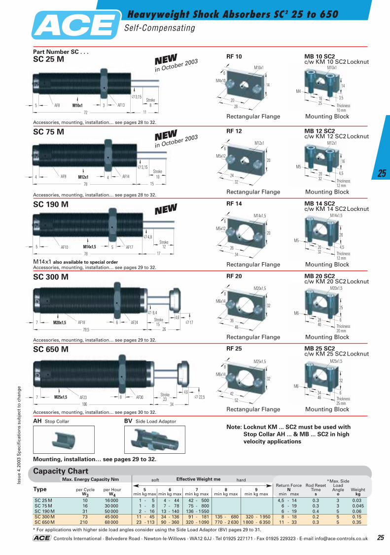
Heavyweight Shock Absorbers SC2 25 to 650Self-Compensating
Issu
e 4.
2003
Sp
ecif
icat
ion
s su
bje
ct t
o c
han
ge
25
25
4,6∅ 22,5M25x1,57 AF23 8
106
AF30 2334
StrokeStrokeAF30AF23
Accessories, mounting, installation… see pages 30 to 32.
Accessories, mounting, installation… see pages 29 to 32.
Accessories, mounting, installation… see pages 29 to 32.
SC 650 M
Part Number SC . . .
∅ 6,44,6
∅ 17M20x1,57 AF18 6
79,5
AF24 1526
StrokeAF18 AF24Stroke
SC 300 M
Rectangular Flange
RF 20
RF 25
Rectangular Flange
Note: Locknut KM ... SC2 must be used with
Stop Collar AH ... & MB ... SC2 in high
velocity applications
46
32
6Breite25 mm
M25x1,5
M634
40
25
6Breite20 mm
M20x1,5
M628
Thickness20 mm
32
20
4,5Breite12 mm
M14x1,5
M520
Thickness12 mm
32
16
4,5Breite12 mm
M12x1
M5
20Thickness12 mm
Thickness25 mm
Mounting Block
MB 20 SC2 c/w KM 20 SC2Locknut
MB 25 SC2 c/w KM 25 SC2Locknut
Mounting Block
AH Stop Collar BV Side Load Adaptor
Mounting, installation… see pages 29 to 32.
46
32
8M20x1,5
36
M6x14
Accessories, mounting, installation… see pages 28 to 32.
∅4,8
M14x1,55 AF10 578
AF17 1217
StrokeAF10 AF17
Stroke
SC 190 M
Rectangular FlangeM14x1 also available to special order
RF 14
Mounting Block
MB 14 SC2 c/w KM 14 SC2Locknut
34
20
6M14x1,5
26
M5x12
Accessories, mounting, installation… see pages 28 to 32.
∅3,15
M12x14 AF9 478
AF14 1015
StrokeAF9 AF14
Stroke
SC 75 M
Rectangular Flange
RF 12
Mounting Block
MB 12 SC2 c/w KM 12 SC2Locknut
32
20
6M12x1
24
M5x12
25
14
3,5Breite10 mm
M10x1
M4
16
Thickness10 mm
Rectangular Flange
RF 10
Mounting Block
MB 10 SC2 c/w KM 10 SC2Locknut
28
14
6M10x1
20
M4x10
∅3,15
M10x15 AF8 3
72
AF13 811
StrokeAF8 AF13
Stroke
SC 25 M
52
32
8M25x1,5
42
M6x14
NEWin October 2003
NEWin October 2003
NEW
Capacity ChartEffective Weight meMax. Energy Capacity Nm
SC 25 M 10 16 000 1 - 5 4 - 44 42 - 500 4,5 - 14 0.3 3 0.03SC 75 M 16 30 000 1 - 8 7 - 78 75 - 800 6 - 19 0.3 3 0.045SC 190 M 31 50 000 2 - 16 13 - 140 136 - 1550 6 - 19 0.4 5 0.06SC 300 M 73 45 000 11 - 45 34 - 136 91 - 181 135 - 680 320 - 1950 8 - 18 0.2 5 0.15SC 650 M 210 68 000 23 - 113 90 - 360 320 - 1090 770 - 2 630 1800 - 6 350 11 - 33 0.3 5 0.35
* For applications with higher side load angles consider using the Side Load Adaptor (BV) pages 29 to 31.
soft hard *Max. SideReturn Force Rod Reset Load
Type per Cycle per Hour 5 6 7 8 9 N Time Angle WeightW3 W4 min kg max min kg max min kg max min kg max min kg max min max s o kg
Controls International · Belvedere Road · Newton-le-Willows · WA12 0JJ · Tel 01925 227171 · Fax 01925 229323 · E-mail [email protected]
ACE-Kat_2003_UK_020-025 22.09.2003 16:15 Uhr Seite 25
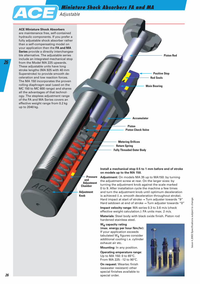
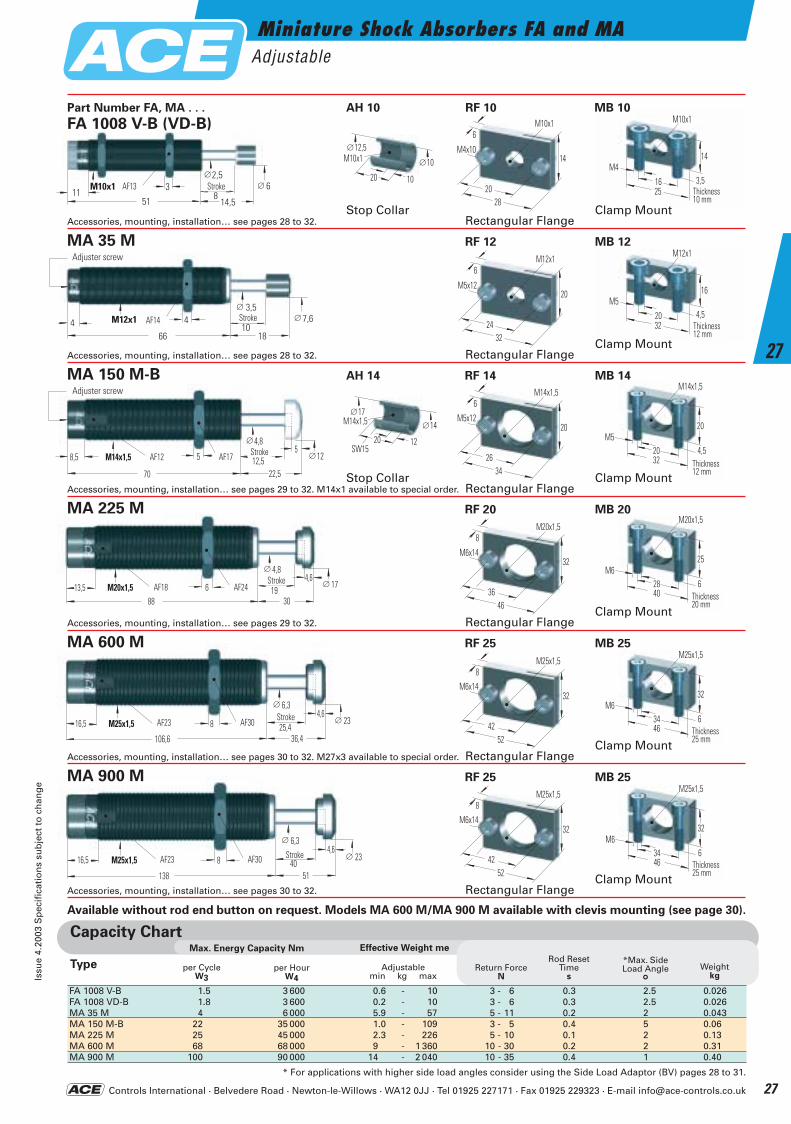
Miniature Shock Absorbers FA and MAAdjustable
Issu
e 4.
2003
Sp
ecif
icat
ion
s su
bje
ct t
o c
han
ge
26
26
Install a mechanical stop 0.5 to 1 mm before end of stroke
on models up to the MA 150.
Adjustment: On models MA 35 up to MA150: by turning the adjustment screw at rear. On the larger sizes: by turning the adjustment knob against the scale marked 0 to 9. After installation cycle the machine a few times and turn the adjustment knob until optimum deceleration is achieved (i.e. smooth deceleration throughout stroke). Hard impact at start of stroke ➞ Turn adjuster towards “9”Hard setdown at end of stroke ➞ Turn adjuster towards “0”
Impact velocity range: MA series 0.3 to 3.6 m/s (check effective weight calculation.): FA units max. 2 m/s.
Materials: Steel body with black oxide finish. Piston rod hardened stainless steel.
W4 capacity rating
(max. energy per hour Nm/hr):
If your application exceeds tabulated W4 figures consider additional cooling i.e. cylinder exhaust air etc.
Mounting: In any position.
Operating emperature range:
Up to MA 150: 0 to 65°C. From MA 225: -12 to 90°C.
On request: Weartec finish (seawater resistant) other special finishes available to special order.
Piston Rod
Positive StopRod Seals
Main Bearing
Accumulator
Piston
Fully Threaded Outer Body
AdjustmentKnob
Pressureand
AdjustmentChamber
Return SpringMetering Orifices
Piston Check Valve
ACE Miniature Shock Absorbers
are maintenance free, self-contained hydraulic components. If you prefer a fully adjustable shock absorber rather than a self-compensating model on your application then the FA and MA
Series provide a directly interchangea-ble alternative. The adjustable seriesinclude an integrated mechanical stopfrom the Model MA 225 upwards.These adjustable units have long stroke lengths (MA 925 with 40 mmSuperstroke) to provide smooth de-celeration and low reaction forces. The MA 150 incorporates the proven rolling diaphragm seal (used on the MC 150 to MC 600 range) and shares all the advantages of that technol-ogy. The stepless adjustment range of the FA and MA Series covers an effective weight range from 0.2 kg up to 2040 kg.
ACE-Kat_2003_UK_026-031 23.09.2003 10:35 Uhr Seite 26
Controls International · Belvedere Road · Newton-le-Willows · WA12 0JJ · Tel 01925 227171 · Fax 01925 229323 · E-mail [email protected]
Miniature Shock Absorbers FA and MAAdjustable
Issu
e 4.
2003
Sp
ecif
icat
ion
s su
bje
ct t
o c
han
ge
27
27
25
14
3,5Breite10 mm
M10x1
M4
16Thickness10 mm
32
16
4,5Breite12 mm
M12x1
M5
20Thickness12 mm
3 StrokeAF 13851
M10x1
14,5
∅2,5∅ 6
11
M10x112,5
20 10
∅
10∅
∅ 4,85
∅12M14x1,58,5 AF12 5
70
AF17 12,522,5
Stroke
Adjuster screw
M14x1,517
20 12
∅
SW15
14∅
∅ 4,84,6
∅ 17M20x1,513,5 AF18 688
AF24 1930
Stroke
∅ 6,34,6
∅ 23M25x1,516,5 AF23 8
106,6
AF30 25,436,4
Stroke
∅ 6,34,6
∅ 23M25x1,516,5 AF23 8
138
AF30 4051
Stroke
4 StrokeAF 1410
66 18
∅ 3,5∅ 7,6M12x14
Adjuster screw
Capacity ChartEffective Weight meMax. Energy Capacity Nm
per Hour W4
per CycleW3
Return ForceN
Rod ResetTime
s
*Max. SideLoad Angle
°Weight
kg
Type Adjustablemin kg max
FA 1008 V-B 1.5 3 600 0.6 - 10 3 - 6 0.3 2.5 0.026FA 1008 VD-B 1.8 3 600 0.2 - 10 3 - 6 0.3 2.5 0.026MA 35 M 4 6 000 5.9 - 57 5 - 11 0.2 2 0.043MA 150 M-B 22 35 000 1.0 - 109 3 - 5 0.4 5 0.06MA 225 M 25 45 000 2.3 - 226 5 - 10 0.1 2 0.13MA 600 M 68 68 000 9 - 1 360 10 - 30 0.2 2 0.31MA 900 M 100 90 000 14 - 2 040 10 - 35 0.4 1 0.40
* For applications with higher side load angles consider using the Side Load Adaptor (BV) pages 28 to 31.
Available without rod end button on request. Models MA 600 M/MA 900 M available with clevis mounting (see page 30).
Adjuster screw
Part Number FA, MA . . .
FA 1008 V-B (VD-B)
Stop CollarRectangular Flange
Clamp MountAccessories, mounting, installation… see pages 28 to 32.
Stop CollarRectangular Flange
Clamp MountAccessories, mounting, installation… see pages 29 to 32. M14x1 available to special order.
Rectangular FlangeClamp Mount
Accessories, mounting, installation… see pages 29 to 32.
Rectangular FlangeClamp Mount
Accessories, mounting, installation… see pages 30 to 32. M27x3 available to special order.
Rectangular FlangeClamp Mount
Accessories, mounting, installation… see pages 30 to 32.
MA 600 M RF 25 MB 25
AF13 Stroke
Stroke
Stroke
Stroke
Stroke
Stroke
AF14
AF12 AF17
AF18 AF24
AF23 AF30
AF23 AF30
32
20
4,5Breite12 mm
M14x1,5
M520
Thickness12 mm
40
25
6Breite20 mm
M20x1,5
M628
Thickness20 mm
46
32
6Breite25 mm
M25x1,5
M634
Thickness25 mm
46
32
6Breite25 mm
M25x1,5
M634
Thickness25 mm
MA 225 M RF 20 MB 20
MA 150 M-B AH 14 RF 14 MB 14
MA 35 M RF 12 MB 12
AH 10 RF 10 MB 10
MA 900 M RF 25 MB 25
Adjuster screw
Rectangular FlangeClamp Mount
Accessories, mounting, installation… see pages 28 to 32.
28
14
6M10x1
20
M4x10
32
20
6M12x1
24
M5x12
34
20
6M14x1,5
26
M5x12
46
32
8M20x1,5
36
M6x14
52
32
8M25x1,5
42
M6x14
52
32
8M25x1,5
42
M6x14
ACE-Kat_2003_UK_026-031 23.09.2003 10:35 Uhr Seite 27
Controls International · Belvedere Road · Newton-le-Willows · WA12 0JJ · Tel 01925 227171 · Fax 01925 229323 · E-mail [email protected]
Shock Absorber Accessories
Issu
e 4.
2003
Sp
ecif
icat
ion
s su
bje
ct t
o c
han
ge
28
28
M6x0,5 / M8x1
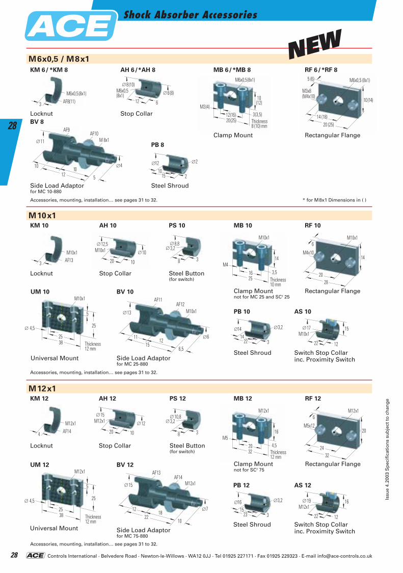
Accessories, mounting, installation… see pages 31 to 32. * for M8x1 Dimensions in ( )
Accessories, mounting, installation… see pages 31 to 32.
Accessories, mounting, installation… see pages 31 to 32.
20(25)
10(12)
3(3,5)Breite8(10) mm
M6x0,5(8x1)
M3(4)12(16)
Clamp Mount
Locknut Stop Collar
Side Load Adaptorfor MC 10-880
M6x0,5(8x1)
8 (10)
12 6
∅
6 (8)∅
12
1010
SW9SW10
5
11∅ M 8x1
4∅
Steel Shroud
∅12 2∅
210
15
M6x0,5 (8x1)
3 AF8(11)
M10x1
25
14
3,5Breite10 mm
M10x1
M4
16Stop Collar
Rectangular Flange
M10x112,5
20 10
∅
10∅
8,8∅
38
3,2∅
Steel Button(for switch)
M10x117
22 12
∅ 15
Switch Stop Collarinc. Proximity SwitchSide Load Adaptor
for MC 25-880
Steel Shroud
∅14 3,2∅
314
22
M12x1
32
16
4,5Breite12 mm
M12x1
M5
20
Clamp Mountnot for SC2 75
Locknut Stop Collar
Rectangular Flange
M12x115
20 10
∅
12∅
32
20
6M12x1
24
M5x12
10,8∅
38
3,2∅
Steel Button(for switch)
M12x119
22 12
∅ 16
Switch Stop Collarinc. Proximity SwitchSide Load Adaptor
for MC 75-880
2212
18
SW13SW14
10
15∅ M12x1
7∅
∅16 3,2∅
315
23
M12x1
4 AF14
AF8(11)
Thickness8 (10) mm
AF10AF9
Thickness10 mm 28
14
6M10x1
20
M4x10
1511
12
SW11SW12
6,5
13∅ M10x1
6∅
AF12
AF14
Thickness12 mm
AF13AF14
RF 10 AH 10
Locknut
M10x1
3 AF13AF13
KM 10
BV 10
PB 10
PS 10
AS 10
RF 12 MB 12 AH 12 KM 12
BV 12
PB 12
PS 12
AS 12
BV 8
MB 10
Steel Shroud
PB 8
20 (25)
10 (14)
5 (6) M6x0,5 (8x1)
14 (18)
M3x8(M4x10)
Rectangular Flange
KM 6/ *KM 8
AF11
AH 6/*AH 8 MB 6/*MB 8 RF 6/*RF 8
Universal Mount
38
25
5
Breite12 mm
M10x1
4,5
25
∅
Thickness12 mm
UM 10
Universal Mount
38
25
5
Breite12 mm
M12x1
4,5
25
∅
Thickness12 mm
UM 12
Clamp Mountnot for MC 25 and SC2 25
NEW
ACE-Kat_2003_UK_026-031 23.09.2003 10:36 Uhr Seite 28
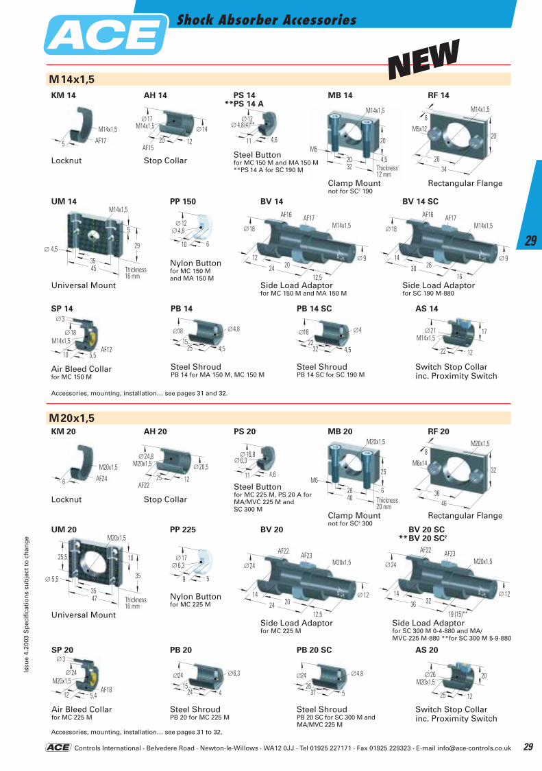
Controls International · Belvedere Road · Newton-le-Willows · WA12 0JJ · Tel 01925 227171 · Fax 01925 229323 · E-mail [email protected]
Shock Absorber AccessoriesIs
sue
4.20
03 S
pec
ific
atio
ns
sub
ject
to
ch
ang
e
29
29
M14x1,5
32
20
4,5Breite12 mm
M14x1,5
M520Locknut Stop Collar
Rectangular Flange
M14x1,517
20 12
∅
SW15
14∅
Nylon Buttonfor MC 150 M and MA 150 M
12∅
610
4,8∅
M14x1,5
5 AF17
M14x1,521
22 12
∅ 17
Switch Stop Collarinc. Proximity Switch
Steel ShroudPB 14 for MA 150 M, MC 150 M
Steel Buttonfor MC 150 M and MA 150 M**PS 14 A for SC 190 M
Steel Buttonfor MC 225 M, PS 20 A for MA/MVC 225 M and SC 300 M
12∅
4,611
4,8(4)**∅
34
20
6M14x1,5
26
M5x12
40
25
6Breite20 mm
M20x1,5
M628
Clamp Mountnot for SC2 300
46
32
8M20x1,5
36
M6x14
Rectangular Flange
Locknut Stop Collar
M20x1,5
6 AF24
M20x1,524,8
25 12
∅
SW22
20,5∅
∅18 4,8∅
4,515
25
Steel ShroudPB 14 SC for SC 190 M
∅18 4∅
4,522
32
M20x1,5
Nylon Button for MC 225 M
Side Load Adaptor for MC 225 M
M20x1,5
∅
24
2414
∅
1220
SW22 SW23
12,5
M20x1,526
25 12
∅ 20
Switch Stop Collarinc. Proximity Switch
Steel ShroudPB 20 for MC 225 M
∅24 6,3∅
415
24
Steel ShroudPB 20 SC for SC 300 M and MA/MVC 225 M
∅24 4,8∅
526
37
16,8∅
4,611
6,3∅
17∅
59
6,3∅
Accessories, mounting, installation… see pages 31 and 32.
Accessories, mounting, installation… see pages 31 to 32.
AF17AF15
Thickness12 mm
AF24AF22
Thickness20 mm
AF22AF23
PS 20
AS 20 PB 20 SC PB 20
PP 225 BV 20
Air Bleed Collarfor MC 225 M
24∅
5,412
M20x1,5SW18
3∅
AF18
SP 20
MB 20 AH 20 KM 20
PB 14 PB 14 SC
PS 14 **PS 14 A
AS 14
18∅
5,510
M14x1,5SW12
3∅
Air Bleed Collarfor MC 150 M
AF12
SP 14
Side Load Adaptorfor SC 190 M-880
M14x1,5
∅
18
3014
∅
926
SW16 SW17
16
BV 14 SC
KM 14 AH 14 MB 14 RF 14
M20x1,5
∅
24
3614
∅
1232
SW22 SW23
19 (15)**Side Load Adaptorfor SC 300 M 0-4-880 and MA/MVC 225 M-880 **for SC 300 M 5-9-880
AF22 AF23
BV 20 SC **BV 20 SC2
AF17AF16
Side Load Adaptor for MC 150 M and MA 150 M
M14x1,5
∅
18
2412
∅
920
SW16 SW17
12,5
BV 14
AF17AF16
RF 20
PP 150
Universal Mount
45
29
5
Breite16 mm
M14x1,5
4,5
35
∅
Thickness16 mm
UM 14
47
35
10
Breite16 mm
M20x1,5
5,5
35
∅
25,5
Universal Mount
Thickness16 mm
UM 20
Clamp Mountnot for SC2 190
NEW
ACE-Kat_2003_UK_026-031 23.09.2003 10:36 Uhr Seite 29
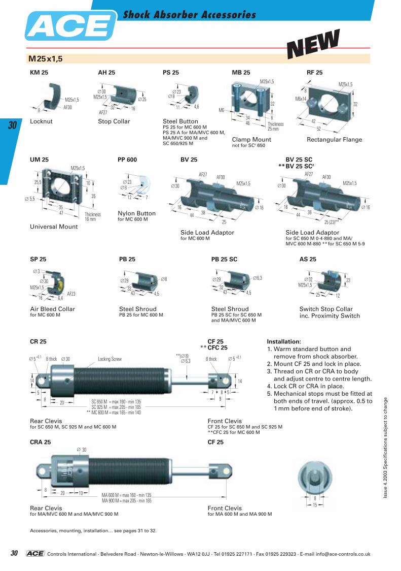
Controls International · Belvedere Road · Newton-le-Willows · WA12 0JJ · Tel 01925 227171 · Fax 01925 229323 · E-mail [email protected]
Shock Absorber Accessories
Issu
e 4.
2003
Sp
ecif
icat
ion
s su
bje
ct t
o c
han
ge
30
30
M25x1,5
46
32
6Breite25 mm
M25x1,5
M634
Clamp Mountnot for SC2 650
Locknut Stop Collar
Rectangular Flange
M25x1,530
32 16
∅
SW27
25∅
30∅
6,416
M25x1,5SW23
3∅
Nylon Buttonfor MC 600 M
Side Load Adaptor for MC 600 M
23∅
712
8∅M25x1,5
∅
30
4416
∅
1638
SW27 SW30
25
Side Load Adaptorfor SC 650 M 0-4-880 and MA/MVC 600 M-880 **for SC 650 M 5-9
Air Bleed Collarfor MC 600 M
M25x1,5
∅
30
4416
∅
1638
SW27 SW30
25 (23)**
M25x1,5
8 AF30
AS 25
M25x1,532
25 12
∅ 23
Switch Stop Collarinc. Proximity Switch
PB 25
Steel ShroudPB 25 for MC 600 M
Installation:
1. Warm standard button and remove from shock absorber.
2. Mount CF 25 and lock in place.3. Thread on CR or CRA to body
and adjust centre to centre length.4. Lock CR or CRA in place.5. Mechanical stops must be fitted at
both ends of travel. (approx. 0.5 to1 mm before end of stroke).
PS 25
Steel ButtonPS 25 for MC 600 M PS 25 A for MA/MVC 600 M, MA/MVC 900 M and SC 650/925 M
23∅
4,611
8∅
52
32
8M25x1,5
42
M6x14
∅29 8∅
4,532
43
PB 25 SC
Steel ShroudPB 25 SC for SC 650 Mand MA/MVC 600 M
∅29 6,3∅
4,532
43
14
5
14
∅
58 20
8 breit 30∅ Sicherungsschraube
SC 650 M = max 160 - min 135SC 925 M = max 205 - min 165
** MC 600 M = max 165 - min 140
8 breit 5∅
5987
6,3∅+0,1+0,1 **( 8)∅
∅
8 20 MA 600 M = max 160 - min 135MA 900 M = max 205 - min 165
10
30
815
Accessories, mounting, installation… see pages 31 to 32.
Thickness25 mm
AF27AF30
AF27 AF30 AF27 AF30
AF23
8 thick Locking Screw 8 thick
Rear Clevisfor SC 650 M, SC 925 M and MC 600 M
Front ClevisCF 25 for SC 650 M and SC 925 M**CFC 25 for MC 600 M
Rear Clevisfor MA/MVC 600 M and MA/MVC 900 M
Front Clevisfor MA 600 M and MA 900 M
KM 25
BV 25 SC
SP 25
CF 25** CFC 25
CR 25
MB 25 RF 25 AH 25
PP 600 BV 25
CF 25 CRA 25
**BV 25 SC2
Universal Mount
47
35
10
Breite16 mm
M25x1,5
5,5
35
25,5
∅
Thickness16 mm
UM 25
NEW
ACE-Kat_2003_UK_026-031 23.09.2003 10:37 Uhr Seite 30
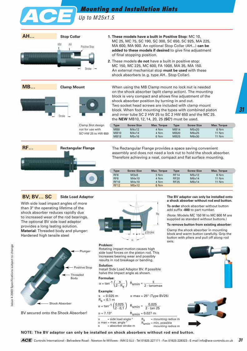
Controls International · Belvedere Road · Newton-le-Willows · WA12 0JJ · Tel 01925 227171 · Fax 01925 229323 · E-mail [email protected]
When using the MB Clamp mount no lock nut is needed on the shock absorber (split clamp action). The mounting block is very compact and allows fine adjustment of the shock absorber position by turning in and out.Two socket head screws are included with clamp mount block. When foot mounting the types with combined piston and inner tube SC 2 HW 25 to SC 2 HW 650 and the MC 25. the NEW MB10, 12, 14, 20, 25 (SC2) must be used.
Mounting and Installation HintsUp to M 25x1.5
Issu
e 4.
2003
Sp
ecif
icat
ion
s su
bje
ct t
o c
han
ge
31
31
Formulae:
Example:
s = 0.025 m a max = 25° (Type BV25)Rs = 0.1 m
( )a = tan-1
a = 7.13°
0.0252 · 0,1
Rsmin =s
2 · tanamax
Rsmin =
Rsmin = 0.027 m
0,0252 · tan 25
Problem:Rotating impact motion causes high side load forces on the piston rod. Thisincreases bearing wear and possibly results in rod breakage or bending.
Solution:Install Side Load Adaptor BV. If possiblehalve the impact angle as shown.
The BV adaptor can only be installed ontoa shock absorber without rod end button.
To order shock absorber without buttonadd suffix -880 to part number.
(Note: Models MC 150 M to MC 600 M aresupplied as standard without buttons.)
To remove button from existing absorber:
Clamp the shock absorber in mounting block and warm button carefully. Grip the button with pliers and pull off along rod axis.
a = side load angle °a max = max. angle °s = absorber stroke m
Rs = mounting radius mRsmin = min. possible
mounting radius m
= =
Rs
s Hub
α
Side Load Adaptor
NOTE: The BV adaptor can only be installed on shock absorbers without rod end button.
With side load impact angles of morethan 3° the operating lifetime of theshock absorber reduces rapidly due to increased wear of the rod bearings. The optional BV side load adaptor provides a long lasting solution. Material: Threaded body and plunger:Hardened high tensile steel
BV secured onto the Shock Absorber!
Plunger
Clamp Slot designnot for use with SC2 HW 25 to HW 650
Positive Stop
Shock Absorber
Stop Collar
Clamp Mount
1. These models have a built in Positive Stop: MC 10, MC 25, MC 75, SC 190, SC 300, SC 650, SC 925, MA 225, MA 600, MA 900. An optional Stop Collar (AH...) can be
added to these models if desired to give fine adjustment of final stopping position.
2. These models do not have a built in positive stop: MC 150, MC 225, MC 600, FA 1008, MA 35, MA 150. An external mechanical stop must be used with these shock absorbers (e.g. type AH.. Stop Collar).
The Rectangular Flange provides a space saving convenient assembly and does not need a lock nut to hold the shock absorber.Therefore achieving a neat, compact and flat surface mounting.
BV; BV… SC
MB…
AH…
KM
Hub
AHFestanschlag
Hub
sa = tan-12 · Rs( )
Stroke
Stroke
Stroke
Positive StopAHKM
Rs
ThreadedBody
Type Screw Size Max. Torque Type Screw Size Max. Torque
RF6 M3x8 3 Nm RF14 M5x12 6 NmRF8 M4x10 4 Nm RF20 M6x14 11 NmRF10 M4x10 4 Nm RF25 M6x14 11 NmRF12 M5x12 6 Nm
Type Screw Size Max. Torque Type Screw Size Max. Torque
MB8 M4x12 4 Nm MB14 M5x20 6 NmMB10 M4x14 4 Nm MB20 M6x25 11 NmMB12 M5x16 6 Nm MB25 M6x30 11 Nm
RF… Rectangular Flange
ACE-Kat_2003_UK_026-031 23.09.2003 10:37 Uhr Seite 31
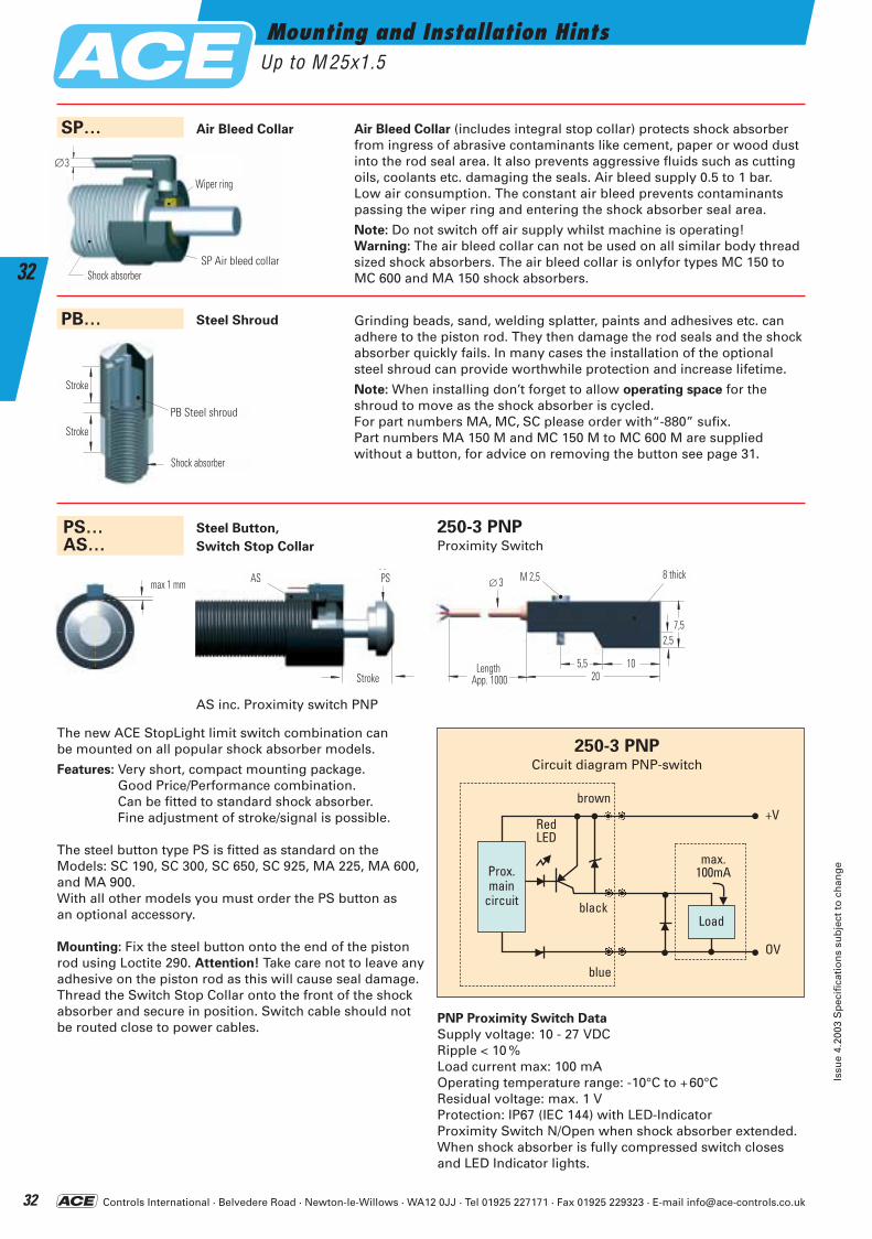
Controls International · Belvedere Road · Newton-le-Willows · WA12 0JJ · Tel 01925 227171 · Fax 01925 229323 · E-mail [email protected]
Mounting and Installation HintsUp to M 25x1.5
Issu
e 4.
2003
Sp
ecif
icat
ion
s su
bje
ct t
o c
han
ge
32
32
Air Bleed Collar (includes integral stop collar) protects shock absorberfrom ingress of abrasive contaminants like cement, paper or wood dustinto the rod seal area. It also prevents aggressive fluids such as cuttingoils, coolants etc. damaging the seals. Air bleed supply 0.5 to 1 bar. Low air consumption. The constant air bleed prevents contaminantspassing the wiper ring and entering the shock absorber seal area.
Note: Do not switch off air supply whilst machine is operating!Warning: The air bleed collar can not be used on all similar body threadsized shock absorbers. The air bleed collar is onlyfor types MC 150 toMC 600 and MA 150 shock absorbers.Stoßdämpfer
Abstreifring
∅3
Air Bleed CollarSP…
SP Air bleed collar
Steel Shroud Grinding beads, sand, welding splatter, paints and adhesives etc. can adhere to the piston rod. They then damage the rod seals and the shockabsorber quickly fails. In many cases the installation of the optional steel shroud can provide worthwhile protection and increase lifetime.
Note: When installing don’t forget to allow operating space for the shroud to move as the shock absorber is cycled.For part numbers MA, MC, SC please order with“-880” sufix.Part numbers MA 150 M and MC 150 M to MC 600 M are supplied without a button, for advice on removing the button see page 31.
PNP Proximity Switch Data
Supply voltage: 10 - 27 VDCRipple < 10 %Load current max: 100 mAOperating temperature range: -10°C to +60°CResidual voltage: max. 1 VProtection: IP67 (IEC 144) with LED-IndicatorProximity Switch N/Open when shock absorber extended.When shock absorber is fully compressed switch closesand LED Indicator lights.
Steel Button,
Switch Stop Collar
The new ACE StopLight limit switch combination can be mounted on all popular shock absorber models.
Features: Very short, compact mounting package. Good Price/Performance combination.Can be fitted to standard shock absorber. Fine adjustment of stroke/signal is possible.
The steel button type PS is fitted as standard on the Models: SC 190, SC 300, SC 650, SC 925, MA 225, MA 600,and MA 900.With all other models you must order the PS button as an optional accessory.
Mounting: Fix the steel button onto the end of the pistonrod using Loctite 290. Attention! Take care not to leave anyadhesive on the piston rod as this will cause seal damage.Thread the Switch Stop Collar onto the front of the shockabsorber and secure in position. Switch cable should notbe routed close to power cables.
PS…AS…
PB…
250-3 PNPCircuit diagram PNP-switch
Prox.main
circuit
Load
max.100mA
RedLED
black
blue
brown+V
OV
PB
Hub
Hub
Stoßdämpfer
max 1 mmPS
Hub
AS 8 breit
20
7,5
105,5
2,5
3∅
ca. 1000Länge
M 2,5
Stroke
8 thick
LengthApp. 1000
Stroke
Stroke
Shock absorber
Wiper ring
Shock absorber
AS inc. Proximity switch PNP
250-3 PNPProximity Switch
PB Steel shroud
AS PS
ACE-Kat_2003_UK_032-037 22.09.2003 17:09 Uhr Seite 32
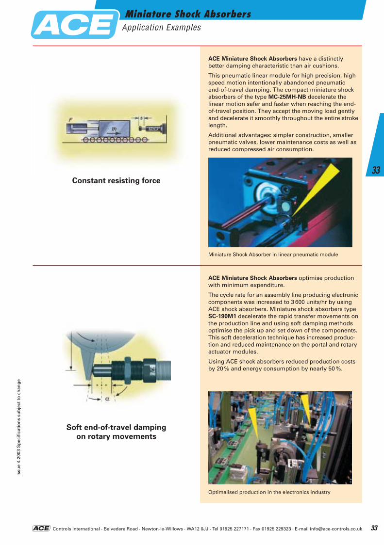
Controls International · Belvedere Road · Newton-le-Willows · WA12 0JJ · Tel 01925 227171 · Fax 01925 229323 · E-mail [email protected]
Soft end-of-travel damping
on rotary movements
Constant resisting force
ACE Miniature Shock Absorbers have a distinctly better damping characteristic than air cushions.
This pneumatic linear module for high precision, highspeed motion intentionally abandoned pneumatic end-of-travel damping. The compact miniature shockabsorbers of the type MC-25MH-NB decelerate the linear motion safer and faster when reaching the end-of-travel position. They accept the moving load gentlyand decelerate it smoothly throughout the entire strokelength.
Additional advantages: simpler construction, smallerpneumatic valves, lower maintenance costs as well asreduced compressed air consumption.
ACE Miniature Shock Absorbers optimise productionwith minimum expenditure.
The cycle rate for an assembly line producing electroniccomponents was increased to 3 600 units/hr by usingACE shock absorbers. Miniature shock absorbers typeSC-190M1 decelerate the rapid transfer movements onthe production line and using soft damping methods optimise the pick up and set down of the components.This soft deceleration technique has increased produc-tion and reduced maintenance on the portal and rotaryactuator modules.
Using ACE shock absorbers reduced production costsby 20 % and energy consumption by nearly 50 %.
Miniature Shock Absorber in linear pneumatic module
Optimalised production in the electronics industry
Miniature Shock AbsorbersApplication Examples
Issu
e 4.
2003
Sp
ecif
icat
ion
s su
bje
ct t
o c
han
ge
33
33
ACE-Kat_2003_UK_032-037 22.09.2003 17:09 Uhr Seite 33
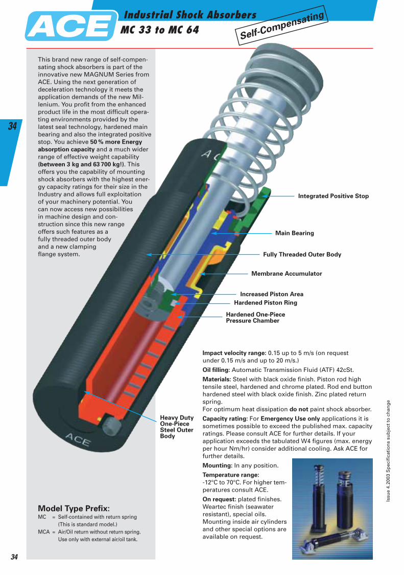
Industrial Shock AbsorbersMC 33 to MC 64
Issu
e 4.
2003
Sp
ecif
icat
ion
s su
bje
ct t
o c
han
ge
34
34
Impact velocity range: 0.15 up to 5 m/s (on request under 0.15 m/s and up to 20 m/s.)
Oil filling: Automatic Transmission Fluid (ATF) 42cSt.
Materials: Steel with black oxide finish. Piston rod hightensile steel, hardened and chrome plated. Rod end buttonhardened steel with black oxide finish. Zinc plated returnspring.For optimum heat dissipation do not paint shock absorber.
Capacity rating: For Emergency Use only applications it is sometimes possible to exceed the published max. capacityratings. Please consult ACE for further details. If your application exceeds the tabulated W4 figures (max. energyper hour Nm/hr) consider additional cooling. Ask ACE for further details.
Mounting: In any position.
Temperature range:
-12°C to 70°C. For higher tem-peratures consult ACE.
On request: plated finishes.Weartec finish (seawater resistant), special oils. Mounting inside air cylindersand other special options areavailable on request.
This brand new range of self-compen-sating shock absorbers is part of the innovative new MAGNUM Series from ACE. Using the next generation of deceleration technology it meets the application demands of the new Mil-lenium. You profit from the enhanced product life in the most difficult opera-ting environments provided by the latest seal technology, hardened main bearing and also the integrated positivestop. You achieve 50 % more Energy
absorption capacity and a much wider range of effective weight capability (between 3 kg and 63 700 kg!). This offers you the capability of mounting shock absorbers with the highest ener-gy capacity ratings for their size in the Industry and allows full exploitation of your machinery potential. You can now access new possibilities in machine design and con-struction since this new range offers such features as a fully threaded outer body and a new clamping flange system.
Model Type Prefix:MC = Self-contained with return spring
(This is standard model.)MCA = Air/Oil return without return spring.
Use only with external air/oil tank.
Integrated Positive Stop
Main Bearing
Fully Threaded Outer Body
Increased Piston Area
Hardened Piston Ring
Hardened One-PiecePressure Chamber
Heavy DutyOne-PieceSteel OuterBody
Self-Compensating
Membrane Accumulator
ACE-Kat_2003_UK_032-037 22.09.2003 17:10 Uhr Seite 34
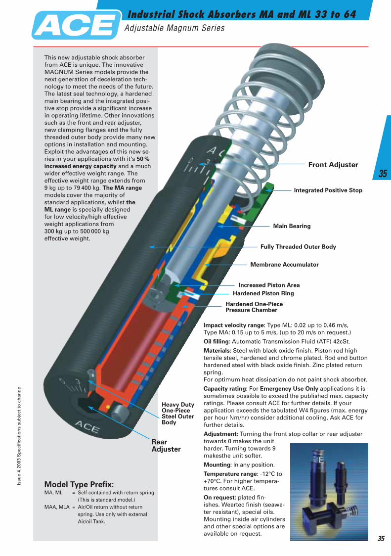
Industrial Shock Absorbers MA and ML 33 to 64Adjustable Magnum Series
Issu
e 4.
2003
Sp
ecif
icat
ion
s su
bje
ct t
o c
han
ge
35
35Integrated Positive Stop
Main Bearing
Fully Threaded Outer Body
Increased Piston Area
Hardened Piston Ring
Hardened One-PiecePressure Chamber
Heavy DutyOne-PieceSteel OuterBody
Impact velocity range: Type ML: 0.02 up to 0.46 m/s, Type MA: 0.15 up to 5 m/s, (up to 20 m/s on request.)
Oil filling: Automatic Transmission Fluid (ATF) 42cSt.
Materials: Steel with black oxide finish. Piston rod hightensile steel, hardened and chrome plated. Rod end buttonhardened steel with black oxide finish. Zinc plated returnspring.For optimum heat dissipation do not paint shock absorber.
Capacity rating: For Emergency Use Only applications it issometimes possible to exceed the published max. capacityratings. Please consult ACE for further details. If your application exceeds the tabulated W4 figures (max. energyper hour Nm/hr) consider additional cooling. Ask ACE forfurther details.
Adjustment: Turning the front stop collar or rear adjuster towards 0 makes the unit harder. Turning towards 9 makesthe unit softer.
Mounting: In any position.
Temperature range: -12°C to +70°C. For higher tempera-tures consult ACE.
On request: plated fin-ishes. Weartec finish (seawa-ter resistant), special oils. Mounting inside air cylinders and other special options are available on request.
Model Type Prefix:MA, ML = Self-contained with return spring
(This is standard model.) MAA, MLA = Air/Oil return without return
spring. Use only with external Air/oil Tank.
This new adjustable shock absorber from ACE is unique. The innovative MAGNUM Series models provide the next generation of deceleration tech-nology to meet the needs of the future. The latest seal technology, a hardened main bearing and the integrated posi-tive stop provide a significant increase in operating lifetime. Other innovations such as the front and rear adjuster, new clamping flanges and the fully threaded outer body provide many newoptions in installation and mounting.Exploit the advantages of this new se-ries in your applications with it's 50 %
increased energy capacity and a much wider effective weight range. The effective weight range extends from9 kg up to 79 400 kg. The MA range
models cover the majority of standard applications, whilst the
ML range is specially designed for low velocity/high effective weight applications from 300 kg up to 500 000 kg effective weight.
Front Adjuster
RearAdjuster
Membrane Accumulator
ACE-Kat_2003_UK_032-037 22.09.2003 17:10 Uhr Seite 35
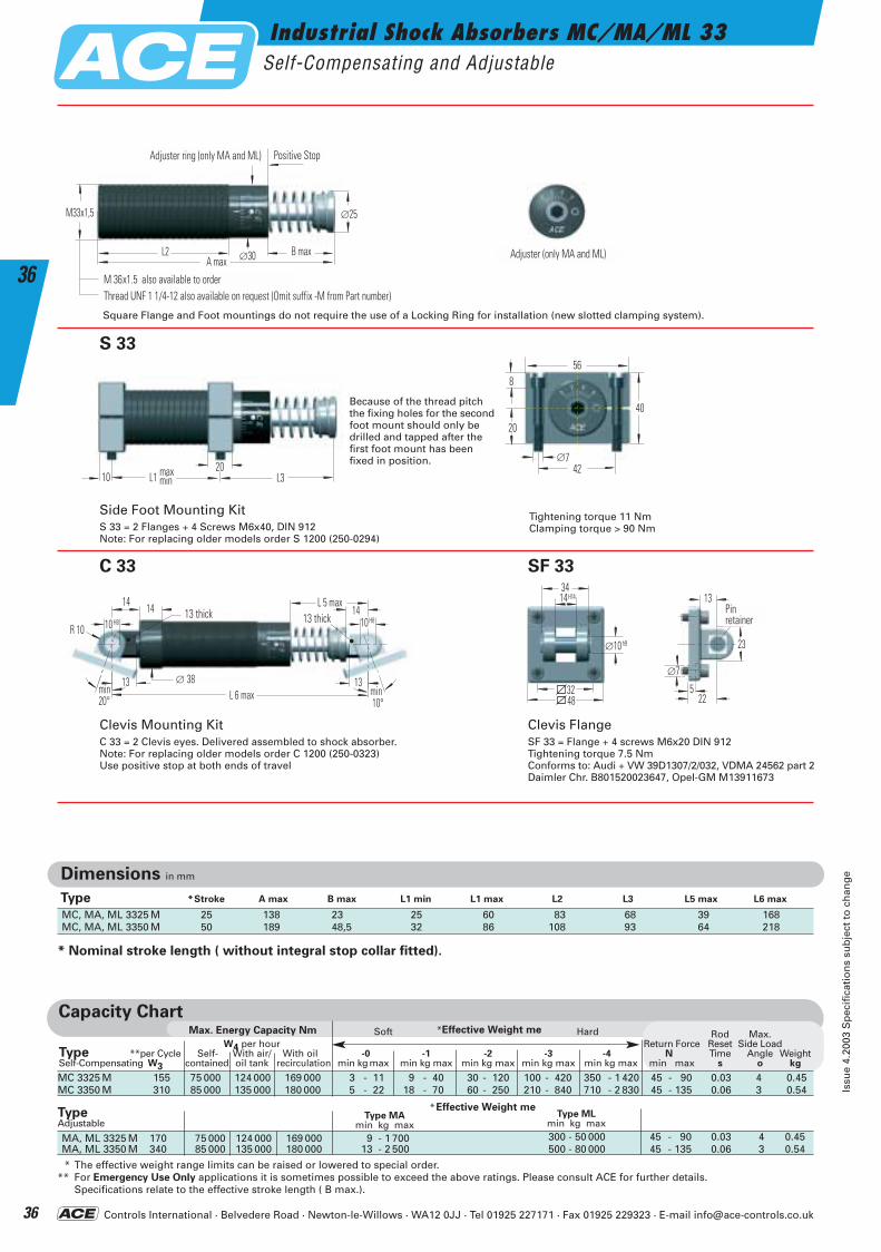
Controls International · Belvedere Road · Newton-le-Willows · WA12 0JJ · Tel 01925 227171 · Fax 01925 229323 · E-mail [email protected]
Industrial Shock Absorbers MC/MA/ML 33Self-Compensating and Adjustable
Issu
e 4.
2003
Sp
ecif
icat
ion
s su
bje
ct t
o c
han
ge
36
36∅30
M33x1,5
L2 B max
∅25
A max
Einstellring (nur MA und ML) Anschlag
Gewinde M36x1,5 und M42x1,5 auf AnfrageGewinde UNF 1 1/4-12
Einstellschraube nur MA und ML
L1 L31020max
min
8
∅742
56
20
40
Bolzen-sicherung
∅7
22
13
5
23∅10 h9
3414
3248
H14
13 breit
L 6 max∅ 38
13 breitL 5 max
R 10
1414
13 13
14
min20°
min 10°
10H8 10H8
M 36x1.5 also available to orderThread UNF 1 1/4-12 also available on request (Omit suffix -M from Part number)
S 33
SF 33 C 33
Clevis Mounting KitC 33 = 2 Clevis eyes. Delivered assembled to shock absorber.Note: For replacing older models order C 1200 (250-0323)Use positive stop at both ends of travel
Side Foot Mounting KitS 33 = 2 Flanges + 4 Screws M6x40, DIN 912Note: For replacing older models order S 1200 (250-0294)
Tightening torque 11 NmClamping torque > 90 Nm
Clevis FlangeSF 33 = Flange + 4 screws M6x20 DIN 912Tightening torque 7.5 Nm Conforms to: Audi + VW 39D1307/2/032, VDMA 24562 part 2 Daimler Chr. B801520023647, Opel-GM M13911673
* Nominal stroke length ( without integral stop collar fitted).
Capacity Chart*Effective Weight meMax. Energy Capacity Nm
MC 3325 M 155 75 000 124 000 169 000 3 - 11 9 - 40 30 - 120 100 - 420 350 - 1 420 45 - 90 0.03 4 0.45MC 3350 M 310 85 000 135 000 180 000 5 - 22 18 - 70 60 - 250 210 - 840 710 - 2 830 45 - 135 0.06 3 0.54
MA, ML 3325 M 170 75 000 124 000 169 000 9 - 1 700 300 - 50 000 45 - 90 0.03 4 0.45MA, ML 3350 M 340 85 000 135 000 180 000 13 - 2 500 500 - 80 000 45 - 135 0.06 3 0.54
* The effective weight range limits can be raised or lowered to special order.** For Emergency Use Only applications it is sometimes possible to exceed the above ratings. Please consult ACE for further details.
Specifications relate to the effective stroke length ( B max.).
Soft Hard
Dimensions in mm
MC, MA, ML 3325 M 25 138 23 25 60 83 68 39 168MC, MA, ML 3350 M 50 189 48,5 32 86 108 93 64 218
*Effective Weight meType MA
min kg maxType ML
min kg max
Rod Max.W4 per hour Return Force Reset Side Load
Type **per Cycle Self- With air/ With oil -0 -1 -2 -3 -4 N Time Angle WeightSelf-Compensating W3 contained oil tank recirculation min kg max min kg max min kg max min kg max min kg max min max s o kg
Type *Stroke A max B max L1 min L1 max L2 L3 L5 max L6 max
Positive StopAdjuster ring (only MA and ML)
Adjuster (only MA and ML)
13 thick 13 thickPinretainer
TypeAdjustable
Because of the thread pitchthe fixing holes for the secondfoot mount should only bedrilled and tapped after thefirst foot mount has beenfixed in position.
Square Flange and Foot mountings do not require the use of a Locking Ring for installation (new slotted clamping system).
ACE-Kat_2003_UK_032-037 22.09.2003 17:10 Uhr Seite 36
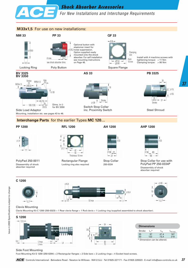
Controls International · Belvedere Road · Newton-le-Willows · WA12 0JJ · Tel 01925 227171 · Fax 01925 229323 · E-mail [email protected]
Shock Absorber AccessoriesFor New Installations and Interchange Requirements
Issu
e 4.
2003
Sp
ecif
icat
ion
s su
bje
ct t
o c
han
ge
37
37
Hub
19
∅38
11
31∅
4254
41
Breite 10mm
28
7∅
2137
33∅
38∅ 4056
33∅
38∅
12,7
19
12,7
∅40
19
12,8
6,4 L1maxL1min
6,4L4
8
∅6,4
12L6 max 7
28
∅6,4
7
20,5
2213
6070
54
∅
6,5
∅39,6
44
Breite10 mm
Klemm-schlitz
32
6,6
M33x1,5 For use on new installations:
Interchange Parts for the earlier Types MC 120…
NM 33 QF 33
Locking Ring
∅29,2
13,2A max.siehe Stoßdämpfer
PP 33
Poly Button
Side Load Adaptor
Square Flange
Steel ShroudMounting, installation etc. see pages 43 to 46.
PP 1200
C 1200
S 1200
RFL 1200 AH 1200 AHP 1200
PolyPad 250-0011Disassembly of shockabsorber required
Clevis MountingClevis Mounting Kit C 1200 (250-0323) = 1 Rear clevis flange + 1 Rod clevis + 1 Locking ring (supplied assembled to shock absorber).
Side Foot MountingFoot Mounting Kit S 1200 (250-0294) = 2 Rectangular flanges + 2 Side bars + 2 Locking rings + 4 Socket head screws.
Rectangular FlangeLocking ring also required
Stop Collar250-0334
Stop Collar for use withPolyPad PP 250-0334PDisassembly of shockabsorber required
M33x1,5Hub23
(48,5)
48 (75)29
(53,5)
M45x1,5
100 (128)
∅30
max.25°
Hub
15∅
35∅
3725
35
Clampingslot
StrokeStroke
Thickness 10 mm
Install with 4 machine screws with tightening torque: = 11 NmClamping torque: > 90 Nm
25 97 47,4 16750 122 73,4 218
* Dimension can be altered.
Dimensions
Stroke L1* L4 L6 max.
thick10 mm
Switch Stop Collarinc. Proximity Switch
Optional button withelastomer insert fornoise suppression. Option supplied ready mounted onto the shock absorber. For self installationsee mounting instructions on Page 46.
Dims. in ()for BV 3350
see shock absorber dims.
BV 3325 BV 3350
AS 33 PB 3325
Stroke
ACE-Kat_2003_UK_032-037 22.09.2003 17:11 Uhr Seite 37

Controls International · Belvedere Road · Newton-le-Willows · WA12 0JJ · Tel 01925 227171 · Fax 01925 229323 · E-mail [email protected]
Industrial Shock Absorbers MC/MA/ML 45Self-Compensating and Adjustable
Issu
e 4.
2003
Sp
ecif
icat
ion
s su
bje
ct t
o c
han
ge
38
38
Capacity Chart
MC 4525 M 340 107 000 158 000 192 000 7 - 27 20 - 90 80 - 310 260 - 1 050 890- 3 540 70 - 100 0.03 4 1.13MC 4550 M 680 112 000 192 000 248 000 13 - 54 45 - 180 150 - 620 520 - 2 090 1 800- 7 100 70 - 145 0.08 3 1.36MC 4575 M 1 020 146 000 225 000 282 000 20 - 80 70 - 270 230 - 930 790 - 3 140 2 650-10 600 50 - 180 0.11 2 1.59
MA, ML 4525 M 390 107 000 158 000 192 000 40 - 10 000 3 000 - 110 000 70 - 100 0.03 4 1.13MA, ML 4550 M 780 112 000 192 000 248 000 70 - 14 500 5 000 - 180 000 70 - 145 0.08 3 1.36MA 4575 M 1 170 146 000 225 000 282 000 70 - 15 000 50 - 180 0.11 2 1.59
* The effective weight range limits can be raised or lowered to special order.** For Emergency Use Only applications it is sometimes possible to exceed the above ratings. Please consult ACE for further details.
Specifications relate to the effective stroke length (B max.).
Dimensions in mm
*Effective Weight me
∅42
M45x1,5
L2 B max
∅35
A max
Einstellring (nur MA und ML) Anschlag
Gewinde UNF 1 3/4-12
Einstellschraube nur MA und ML
MC, MA, ML 4525 M 25 145 23 32 66 95 66 43 200MC, MA, ML 4550 M 50 195 48.5 40 92 120 91 68 250MC, MA 4575 M 75 246 74 50 118 145 116 93 300
Type *Stroke A max B max L1 min L1 max L2 L3 L5 max L6 max
Type MAmin kg max
Type MLmin kg max
L1 L312,525max
min
16
∅960
80
28
56
Bolzen-sicherung
∅9
27
15
6
29∅16 h9
4521
4665
H14
20 breit
L 6 max∅ 53
20 breitL 5 max
R 14
2028
20 17
18
min15°
min15°
16H8 16H8
* Nominal stroke length (without integral stop collar fitted).
S 45
Side Foot Mounting KitS 45 = 2 Flanges + 4 Screws M 8x50, DIN 912Note: For replacing older models order S 1400 (250-0300)
Clevis FlangeSF 45 = Flange + 4 screws M 8x20 DIN 912Tightening torque 7.5 Nm Conforms to: Audi + VW 39D1307/2/050, VDMA 24562 part 2 Daimler Chr. B801520023647, Opel-GM M13911675
Clevis Mounting KitC 45 = 2 Clevis eyes. Delivered assembled to shock absorber.Note: For replacing older models order C 1400 (250-0325)Use positive stop at both ends of travel
Positive StopAdjuster ring (only MA and ML)
Adjuster (only MA and ML)
20 thick 20 thickPinretainer
Tightening torque 27 NmClamping torque > 350 Nm
TypeAdjustable
SF 45 C 45
Because of the thread pitchthe fixing holes for the secondfoot mount should only bedrilled and tapped after thefirst foot mount has beenfixed in position.
Thread UNF 1 3/4-12 also available on request (Omit suffix -M from Part number)
Rod Max.**per W4 per Hour Return Force Reset Side Load
Type Cycle Self- with Air/ with Oil -0 -1 -2 -3 -4 N Time Angle WeightSelf-Compensating W3 Contained Oil Tank Recirculation min kg max min kg max min kg max min kg max min kg max min max s o kg
Soft Hard*Effective Weight meMax. Energy Capacity Nm
ACE-Kat_2003_UK_038-043 23.09.2003 11:01 Uhr Seite 38
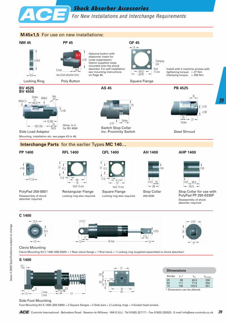
Controls International · Belvedere Road · Newton-le-Willows · WA12 0JJ · Tel 01925 227171 · Fax 01925 229323 · E-mail [email protected]
Shock Absorber AccessoriesFor New Installations and Interchange Requirements
Issu
e 4.
2003
Sp
ecif
icat
ion
s su
bje
ct t
o c
han
ge
39
39
17,5
45∅
41,257
57
Breite 13mm
41,2
9∅19
38
45∅
57∅ 36,555,5
50∅
57∅
13
25,4
25,4
19
∅57
26
13
∅12,7
27L6 max 13
∅9,5
17,5
9,5
∅55,6
56
Breite12 mm
Klemm-schlitz
42
9
M45x1,5 For use on new installations:
Interchange Parts for the earlier Types MC 140…
NM 45 QF 45
Side Load AdaptorSwitch Stop Collarinc. Proximity Switch Steel Shroud
Mounting, installation etc. see pages 43 to 46.
S 1400
PolyPad 250-0001Disassembly of shockabsorber required
Clevis MountingClevis Mounting Kit C 1400 (250-0325) = 1 Rear clevis flange + 1 Rod clevis + 1 Locking ring (supplied assembled to shock absorber).
Side Foot MountingFoot Mounting Kit S 1400 (250-0300) = 2 Square flanges + 2 Side bars + 2 Locking rings + 4 Socket head screws.
Square FlangeLocking ring also required
Rectangular FlangeLocking ring also required
Stop Collar250-0335
Stop Collar for use withPolyPad PP 250-0335PDisassembly of shockabsorber required
6076
57
Breite 13 mm
41,2
9∅
Hub
20∅
48∅
3725
35
6,5
13 L1maxL1min
22 6,5
L410
9
28,5
29,514
7695
57
∅
Square FlangeLocking Ring
Clampingslot
Stroke
thick 13 mm thick 13 mm
25 89 49,5 20050 111 77,5 25075 136 103,5 301
* Dimension can be altered.
Dimensions
Stroke L1* L4 L6 max.
Install with 4 machine screws with tightening torque: = 27 NmClamping torque: > 200 Nm
thick12 mm
AHP 1400 AH 1400 QFL 1400 RFL 1400 PP 1400
C 1400
Hub
29
∅57
M45x1,5Hub23
(48,5)
52 (80)29
(54,5)
M64x2
100 (130)
∅40
max.20°
Stroke
Stroke
∅42
19,4A max.siehe Stoßdämpfer
PP 45
Poly Button
Optional button withelastomer insert fornoise suppression. Option supplied ready mounted onto the shock absorber. For self installation see mounting instructions on Page 46.see shock absorber dims.
BV 4525 BV 4550
PB 4525 AS 45
Dims. in ()for BV 4550
ACE-Kat_2003_UK_038-043 23.09.2003 11:02 Uhr Seite 39
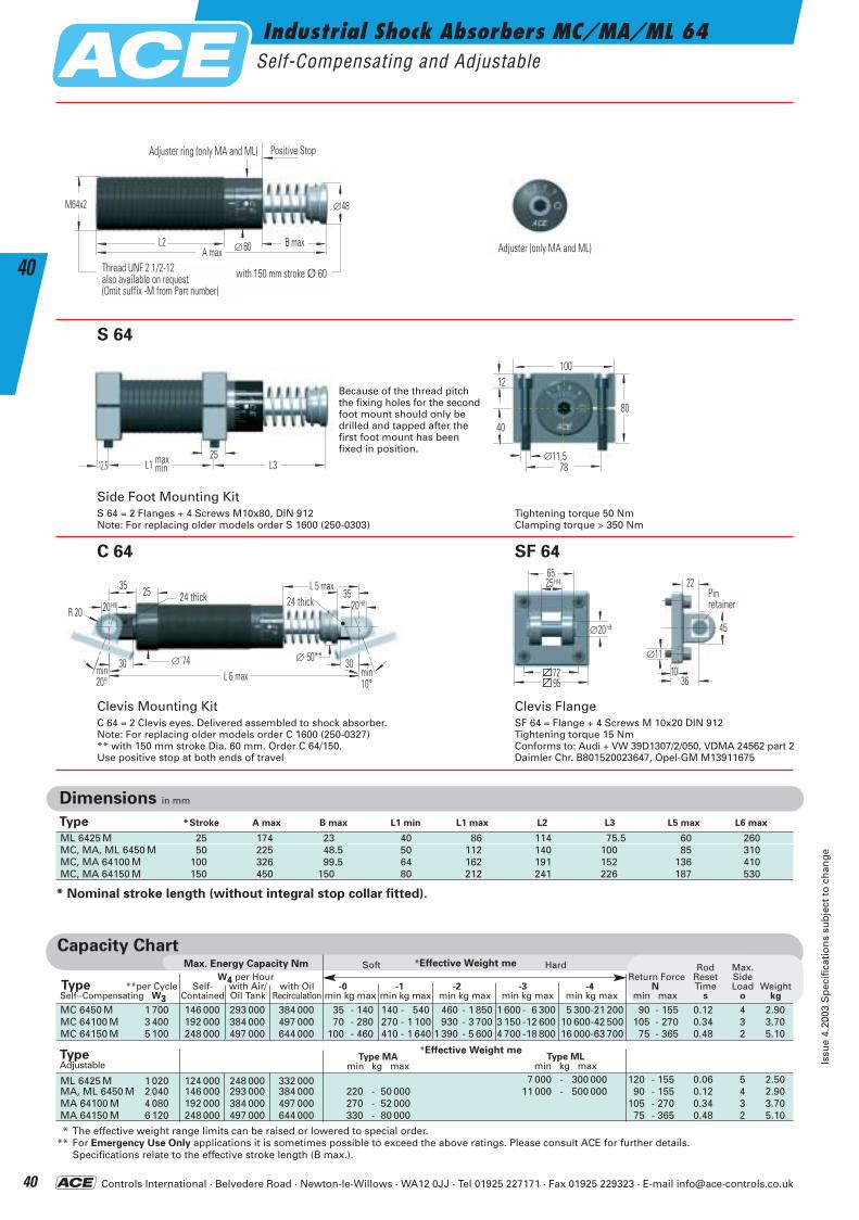
Controls International · Belvedere Road · Newton-le-Willows · WA12 0JJ · Tel 01925 227171 · Fax 01925 229323 · E-mail [email protected]
Industrial Shock Absorbers MC/MA/ML 64Self-Compensating and Adjustable
Issu
e 4.
2003
Sp
ecif
icat
ion
s su
bje
ct t
o c
han
ge
40
40∅60
M64x2
L2 B max
∅48
A max
Einstellring (nur MA und ML) Anschlag
bei 150 Hub ∅60Gewinde UNF 2 1/2-12
Einstellschraube nur MA und ML
bei 150 Hub Ø 60
Capacity Chart*Effective Weight meMax. Energy Capacity Nm
MC 6450 M 1 700 146 000 293 000 384 000 35 - 140 140 - 540 460 - 1 850 1 600 - 6 300 5 300-21 200 90 - 155 0.12 4 2.90MC 64100 M 3 400 192 000 384 000 497 000 70 - 280 270 - 1 100 930 - 3 700 3 150 -12 600 10 600-42 500 105 - 270 0.34 3 3.70MC 64150 M 5 100 248 000 497 000 644 000 100 - 460 410 - 1 640 1 390 - 5 600 4 700 -18 800 16 000-63 700 75 - 365 0.48 2 5.10
ML 6425 M 1 020 124 000 248 000 332 000 7 000 - 300 000 120 - 155 0.06 5 2.50MA, ML 6450 M 2 040 146 000 293 000 384 000 220 - 50 000 11 000 - 500 000 90 - 155 0.12 4 2.90MA 64100 M 4 080 192 000 384 000 497 000 270 - 52 000 105 - 270 0.34 3 3.70MA 64150 M 6 120 248 000 497 000 644 000 330 - 80 000 75 - 365 0.48 2 5.10
* The effective weight range limits can be raised or lowered to special order.** For Emergency Use Only applications it is sometimes possible to exceed the above ratings. Please consult ACE for further details.
Specifications relate to the effective stroke length (B max.).
Soft Hard
Dimensions in mm
ML 6425 M 25 174 23 40 86 114 75.5 60 260MC, MA, ML 6450 M 50 225 48.5 50 112 140 100 85 310MC, MA 64100 M 100 326 99.5 64 162 191 152 136 410MC, MA 64150 M 150 450 150 80 212 241 226 187 530
*Effective Weight meType MA
min kg maxType ML
min kg max
Rod Max.W4 per Hour Return Force Reset Side
Type **per Cycle Self- with Air/ with Oil -0 -1 -2 -3 -4 N Time Load WeightSelf--Compensating W3 Contained Oil Tank Recirculation min kg max min kg max min kg max min kg max min kg max min max s o kg
Type *Stroke A max B max L1 min L1 max L2 L3 L5 max L6 max
L1 L312,525max
min
12
∅11,578
100
40
80
Bolzen-sicherung
∅11
36
22
10
45∅20 h9
6525
7295
H14
24 breit
L 6 max∅ 74
24 breitL 5 max
R 20
2535
30 30
35
min20°
min10°
20H8 20H8
∅ 50**
S 64
C 64
Clevis Mounting KitC 64 = 2 Clevis eyes. Delivered assembled to shock absorber.Note: For replacing older models order C 1600 (250-0327)** with 150 mm stroke Dia. 60 mm. Order C 64/150.Use positive stop at both ends of travel
Side Foot Mounting KitS 64 = 2 Flanges + 4 Screws M10x80, DIN 912Note: For replacing older models order S 1600 (250-0303)
SF 64
Clevis FlangeSF 64 = Flange + 4 Screws M 10x20 DIN 912Tightening torque 15 Nm Conforms to: Audi + VW 39D1307/2/050, VDMA 24562 part 2 Daimler Chr. B801520023647, Opel-GM M13911675
* Nominal stroke length (without integral stop collar fitted).
Adjuster (only MA and ML)
Positive StopAdjuster ring (only MA and ML)
24 thick 24 thickPinretainer
Tightening torque 50 NmClamping torque > 350 Nm
TypeAdjustable
Because of the thread pitchthe fixing holes for the secondfoot mount should only bedrilled and tapped after thefirst foot mount has beenfixed in position.
Thread UNF 2 1/2-12also available on request(Omit suffix -M from Part number)
with 150 mm stroke Ø 60
ACE-Kat_2003_UK_038-043 23.09.2003 11:02 Uhr Seite 40
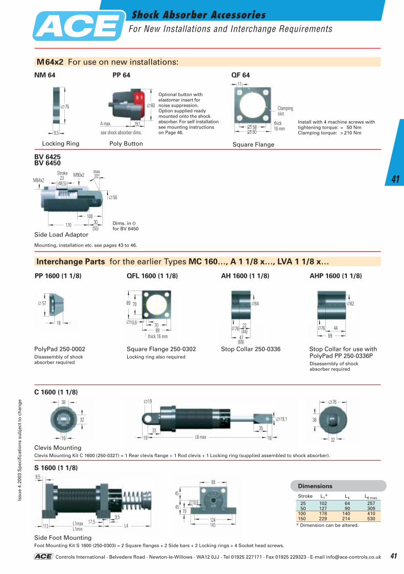
Controls International · Belvedere Road · Newton-le-Willows · WA12 0JJ · Tel 01925 227171 · Fax 01925 229323 · E-mail [email protected]
Shock Absorber AccessoriesFor New Installations and Interchange Requirements
Issu
e 4.
2003
Sp
ecif
icat
ion
s su
bje
ct t
o c
han
ge
41
41
9,5
∅76
80
Breite16 mm
Klemm-schlitz
58
11
22
64∅
76∅
(69)
(44)47
7089
89
Breite 16 mm
70
10,6∅18
57∅
4469
62∅
76∅
16
38
32
32
∅76
38
19
∅19
33L6 max 16
35
∅19,1
9,5
17,5 L1maxL1min
9,5
L417,5
10,6
45
4519
124143
89
∅
Interchange Parts for the earlier Types MC 160…, A 1 1/8 x…, LVA 1 1/8 x…
PP 1600 (1 1/8)
S 1600 (1 1/8)
QFL 1600 (1 1/8) AH 1600 (1 1/8) AHP 1600 (1 1/8)
PolyPad 250-0002Disassembly of shockabsorber required
Clevis MountingClevis Mounting Kit C 1600 (250-0327) = 1 Rear clevis flange + 1 Rod clevis + 1 Locking ring (supplied assembled to shock absorber).
Side Foot MountingFoot Mounting Kit S 1600 (250-0303) = 2 Square flanges + 2 Side bars + 2 Locking rings + 4 Socket head screws.
Square Flange 250-0302Locking ring also required
Stop Collar 250-0336 Stop Collar for use withPolyPad PP 250-0336PDisassembly of shockabsorber required
M64x2 For use on new installations:
NM 64 QF 64
Locking Ring Square Flange
thick 16 mm
Clampingslot
25 102 64 25750 127 90 309
100 178 140 410150 229 214 530
* Dimension can be altered.
Dimensions
Stroke L1* L4 L6 max.
Install with 4 machine screws with tightening torque: = 50 NmClamping torque: > 210 Nm
thick16 mm
C 1600 (1 1/8)
∅60
19,1A max.siehe Stoßdämpfer
PP 64
Poly Button
Optional button withelastomer insert fornoise suppression. Option supplied ready mounted onto the shock absorber. For self installationsee mounting instructions on Page 46.see shock absorber dims.
Side Load Adaptor
Mounting, installation etc. see pages 43 to 46.
M64x2Hub23
(48,5)
10030(55)
M90x2
170
∅56
max.20°
Stroke
BV 6425 BV 6450
Dims. in ()for BV 6450
ACE-Kat_2003_UK_038-043 23.09.2003 11:03 Uhr Seite 41
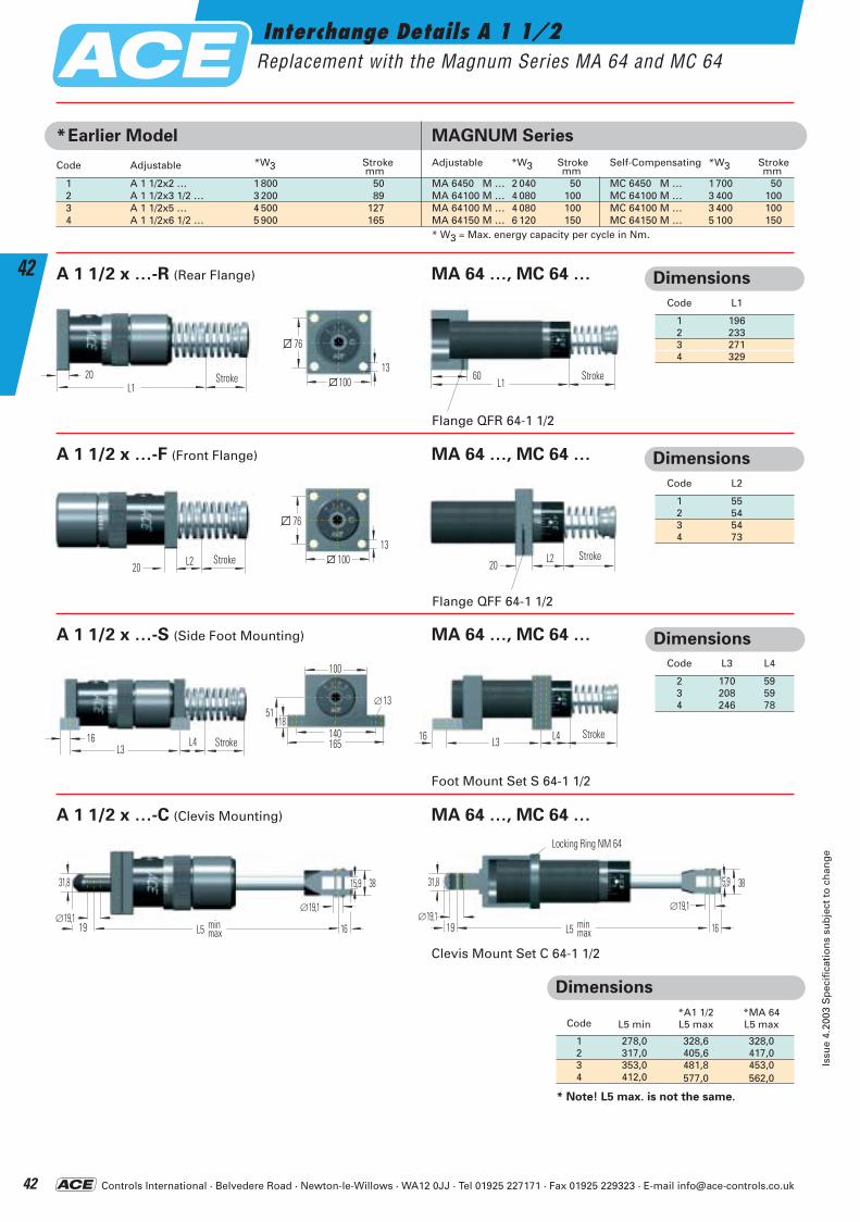
Controls International · Belvedere Road · Newton-le-Willows · WA12 0JJ · Tel 01925 227171 · Fax 01925 229323 · E-mail [email protected]
Interchange Details A 1 1/2Replacement with the Magnum Series MA 64 and MC 64
Issu
e 4.
2003
Sp
ecif
icat
ion
s su
bje
ct t
o c
han
ge
42
42
*Earlier Model MAGNUM Series
Code Adjustable *W3 Stroke Adjustable *W3 Stroke Self-Compensating *W3 Strokemm mm mm
1 A 1 1/2x2 … 1 800 50 MA 6450 M … 2 040 50 MC 6450 M … 1 700 502 A 1 1/2x3 1/2 … 3 200 89 MA 64100 M … 4 080 100 MC 64100 M … 3 400 1003 A 1 1/2x5 … 4 500 127 MA 64100 M … 4 080 100 MC 64100 M … 3 400 1004 A 1 1/2x6 1/2 … 5 900 165 MA 64150 M … 6 120 150 MC 64150 M … 5 100 150
* W3 = Max. energy capacity per cycle in Nm.
A 1 1/2 x …-R (Rear Flange) MA 64 …, MC 64 …
L120 Hub 60 HubL1100
76
13
A 1 1/2 x …-F (Front Flange) MA 64 …, MC 64 …
L220 Hub 20 HubL2100
76
13
A 1 1/2 x …-S (Side Foot Mounting) MA 64 …, MC 64 …
L416 HubL3L3 HubL416140
5113
165
18
∅
100
A 1 1/2 x …-C (Clevis Mounting) MA 64 …, MC 64 …
31,8
∅19,119
∅19,1
16
15,9 38
L5 minmax
31,8
∅19,119
∅19,1
16
15,9 38
L5 minmax
Nutmutter NM 64
Dimensions
*A1 1/2 *MA 64Code L5 min L5 max L5 max
1 278,0 328,6 328,02 317,0 405,6 417,03 353,0 481,8 453,04 412,0 577,0 562,0
* Note! L5 max. is not the same.
Dimensions
Code L3 L4
2 170 593 208 594 246 78
Dimensions
Code L2
1 552 543 544 73
Dimensions
Code L1
1 1962 2333 2714 329
Flange QFR 64-1 1/2
Flange QFF 64-1 1/2
Clevis Mount Set C 64-1 1/2
Foot Mount Set S 64-1 1/2
Stroke Stroke
Stroke Stroke
StrokeStroke
Locking Ring NM 64
ACE-Kat_2003_UK_038-043 23.09.2003 11:03 Uhr Seite 42
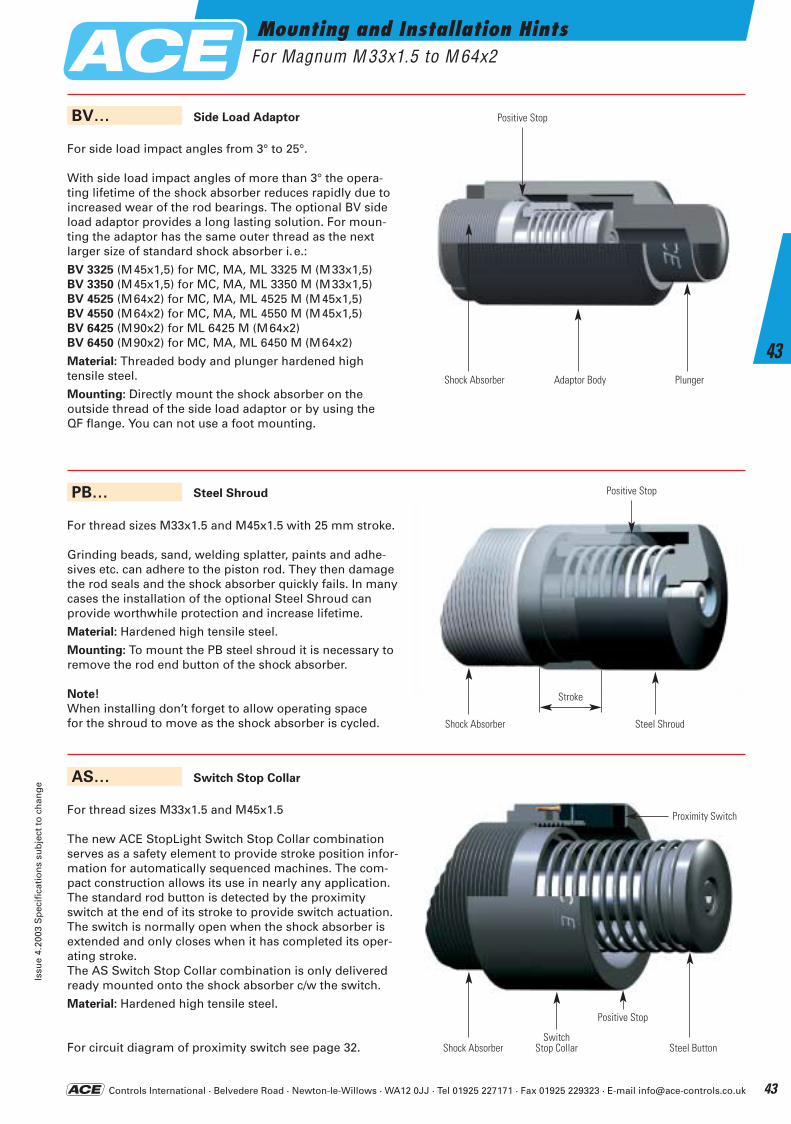
Controls International · Belvedere Road · Newton-le-Willows · WA12 0JJ · Tel 01925 227171 · Fax 01925 229323 · E-mail [email protected]
Mounting and Installation HintsFor Magnum M 33x1.5 to M 64x2
Issu
e 4.
2003
Sp
ecif
icat
ion
s su
bje
ct t
o c
han
ge
43
43
Side Load Adaptor
For side load impact angles from 3° to 25°.
With side load impact angles of more than 3° the opera-ting lifetime of the shock absorber reduces rapidly due toincreased wear of the rod bearings. The optional BV sideload adaptor provides a long lasting solution. For moun-ting the adaptor has the same outer thread as the next larger size of standard shock absorber i.e.:
BV 3325 (M45x1,5) for MC, MA, ML 3325 M (M33x1,5)BV 3350 (M45x1,5) for MC, MA, ML 3350 M (M33x1,5)BV 4525 (M64x2) for MC, MA, ML 4525 M (M45x1,5)BV 4550 (M64x2) for MC, MA, ML 4550 M (M45x1,5)BV 6425 (M90x2) for ML 6425 M (M64x2)BV 6450 (M90x2) for MC, MA, ML 6450 M (M64x2)
Material: Threaded body and plunger hardened high tensile steel.
Mounting: Directly mount the shock absorber on the outside thread of the side load adaptor or by using the QF flange. You can not use a foot mounting.
BV…
Steel Shroud
For thread sizes M33x1.5 and M45x1.5 with 25 mm stroke.
Grinding beads, sand, welding splatter, paints and adhe-sives etc. can adhere to the piston rod. They then damage the rod seals and the shock absorber quickly fails. In many cases the installation of the optional Steel Shroud can provide worthwhile protection and increase lifetime.
Material: Hardened high tensile steel.
Mounting: To mount the PB steel shroud it is necessary toremove the rod end button of the shock absorber.
Note!
When installing don’t forget to allow operating space for the shroud to move as the shock absorber is cycled.
PB…
Switch Stop Collar
For thread sizes M33x1.5 and M45x1.5
The new ACE StopLight Switch Stop Collar combinationserves as a safety element to provide stroke position infor-mation for automatically sequenced machines. The com-pact construction allows its use in nearly any application.The standard rod button is detected by the proximityswitch at the end of its stroke to provide switch actuation.The switch is normally open when the shock absorber isextended and only closes when it has completed its oper-ating stroke.The AS Switch Stop Collar combination is only deliveredready mounted onto the shock absorber c/w the switch.
Material: Hardened high tensile steel.
For circuit diagram of proximity switch see page 32.
AS…
Shock Absorber Adaptor Body Plunger
Shock Absorber
Stroke
Steel Shroud
Shock AbsorberSwitch
Stop Collar Steel Button
Positive Stop
Positive Stop
Proximity Switch
Positive Stop
ACE-Kat_2003_UK_038-043 23.09.2003 11:04 Uhr Seite 43
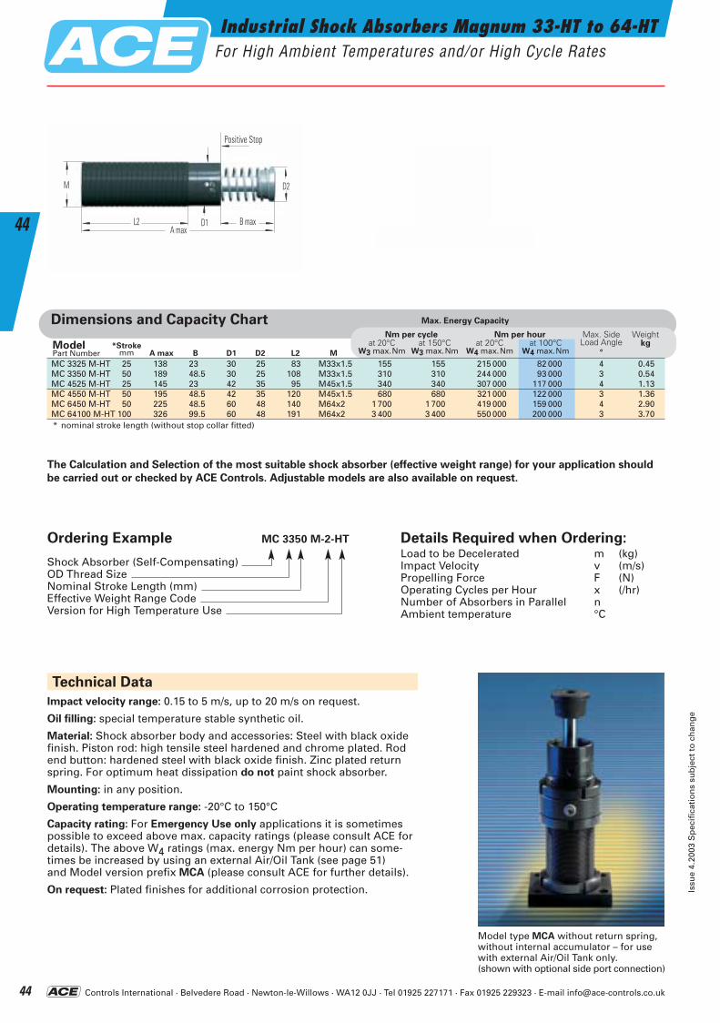
Controls International · Belvedere Road · Newton-le-Willows · WA12 0JJ · Tel 01925 227171 · Fax 01925 229323 · E-mail [email protected]
Industrial Shock Absorbers Magnum 33-HT to 64-HTFor High Ambient Temperatures and/or High Cycle Rates
Issu
e 4.
2003
Sp
ecif
icat
ion
s su
bje
ct t
o c
han
ge
44
44 D1
M
L2 B max
D2
A max
AnschlagPositive Stop
Ordering Example MC 3350 M-2-HT
Shock Absorber (Self-Compensating)OD Thread SizeNominal Stroke Length (mm)Effective Weight Range CodeVersion for High Temperature Use
Details Required when Ordering:Load to be Decelerated m (kg)Impact Velocity v (m/s)Propelling Force F (N)Operating Cycles per Hour x (/hr)Number of Absorbers in Parallel nAmbient temperature °C
Technical Data
Impact velocity range: 0.15 to 5 m/s, up to 20 m/s on request.
Oil filling: special temperature stable synthetic oil.
Material: Shock absorber body and accessories: Steel with black oxidefinish. Piston rod: high tensile steel hardened and chrome plated. Rodend button: hardened steel with black oxide finish. Zinc plated returnspring. For optimum heat dissipation do not paint shock absorber.
Mounting: in any position.
Operating temperature range: -20°C to 150°C
Capacity rating: For Emergency Use only applications it is sometimespossible to exceed above max. capacity ratings (please consult ACE fordetails). The above W4 ratings (max. energy Nm per hour) can some-times be increased by using an external Air/Oil Tank (see page 51) and Model version prefix MCA (please consult ACE for further details).
On request: Plated finishes for additional corrosion protection.
Dimensions and Capacity Chart
A max B D1 D2*Stroke
mmModelPart Number
Max. SideLoad Angle
°
Weight kg
L2 M
The Calculation and Selection of the most suitable shock absorber (effective weight range) for your application should
be carried out or checked by ACE Controls. Adjustable models are also available on request.
Model type MCA without return spring, without internal accumulator – for use with external Air/Oil Tank only.(shown with optional side port connection)
MC 3325 M-HT 25 138 23 30 25 83 M33x1.5 155 155 215 000 82 000 4 0.45MC 3350 M-HT 50 189 48.5 30 25 108 M33x1.5 310 310 244 000 93 000 3 0.54MC 4525 M-HT 25 145 23 42 35 95 M45x1.5 340 340 307 000 117 000 4 1.13MC 4550 M-HT 50 195 48.5 42 35 120 M45x1.5 680 680 321000 122 000 3 1.36MC 6450 M-HT 50 225 48.5 60 48 140 M64x2 1 700 1 700 419 000 159 000 4 2.90MC 64100 M-HT 100 326 99.5 60 48 191 M64x2 3 400 3 400 550 000 200 000 3 3.70* nominal stroke length (without stop collar fitted)
Nm per cycle Nm per hourat 20°C at 150°C at 20°C at 100°C
W3 max.Nm W3 max.Nm W4 max.Nm W4 max.Nm
Max. Energy Capacity
ACE-Kat_2003_UK_044-049 22.09.2003 17:22 Uhr Seite 44
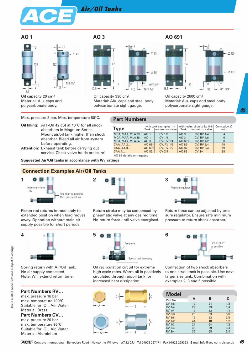
Controls International · Belvedere Road · Newton-le-Willows · WA12 0JJ · Tel 01925 227171 · Fax 01925 229323 · E-mail [email protected]
Air/Oil TanksIs
sue
4.20
03 S
pec
ific
atio
ns
sub
ject
to
ch
ang
e
45
45
22
∅ 43
2,5
NPT 1/8’’
102
7
8,5
138
17
195
10,2
95
NPTF 1/2’’(G 3/8’’)**
47,5
3
∅ 86
NPTF 3/8’’ 20
334
16,5
165
NPTF 3/4’’(G 3/4’’)**
92
5
∅ 152
Oil capacity 20 cm3
Material: Alu. caps andpolycarbonate body.
Piston rod returns immediately to extended position when load moves away. Operation without main air supply possible for short periods.
Spring return with Air/Oil Tank. No air supply connected. Note: Will extend return time.
Return stroke may be sequenced by pneumatic valve at any desired time. No return force until valve energised.
Oil recirculation circuit for extreme high cycle rates. Warm oil is positively circulated through air/oil tank for increased heat dissipation.
Part Numbers RV…max. pressure 16 barmax. temperature 100°CSuitable for: Oil, Air, Water. Material: BrassPart Numbers CV…max. pressure 20 barmax. temperature 95°CSuitable for: Oil, Air, Water. Material: Aluminium
Return force can be adjusted by pres-sure regulator. Ensure safe minimum pressure to return shock absorber.
Connection of two shock absorbers to one air/oil tank is possible. Use next larger size tank. Combination with examples 2, 3 and 5 possible.
Connection Examples Air/Oil Tanks
Non-return valve – RV –
Pipe short as possible.Max. pressure 8 bar
Oil capacity 330 cm3
Material: Alu. caps and steel bodypolycarbonate sight gauge.
Oil capacity 2600 cm3
Material: Alu. caps and steel bodypolycarbonate sight gauge.
Max. pressure 8 bar. Max. temperature 80°C.
Oil filling: ATF-Oil 42 cSt at 40°C for all shock absorbers in Magnum Series.Mount air/oil tank higher than shockabsorber. Bleed all air from systembefore operating.
Attention: Exhaust tank before carrying outservice. Check valve holds pressure!
Suggested Air/Oil tanks in accordance with W4 ratings
1
4
2
5
3
6
ModelPart No. CV 1/8 19 24 1/8CV 1/4 29 33 1/4RV 1/4 19 53 1/4CV 3/8 29 33 3/8RV 3/8 19 53 3/8CV 1/2 41 40 1/2RV 1/2 24 64 1/2CV 3/4 48 59 3/4RV 3/4 36 58 3/4
Part Numbers
MCA, MAA, MLA 33… AO 1 CV 1/8 AO 3 CV, RV 1/4 4MCA, MAA, MLA 45… AO 1 CV 1/8 AO 3 CV, RV 3/8 6MCA, MAA, MLA 64… AO 3 CV, RV 1/4 AO 691 CV, RV 1/2 8CAA, AA 2… AO 691 CV, RV 1/2 AO 82 CV, RV 3/4 15CAA, AA 3… AO 691 CV, RV 1/2 AO 82 CV, RV 3/4 19CAA 4… AO 82 CV 3/4 AO 82 CV 3/4 38AO 82 details on request.
with tank examples 1-4 with recirc. circuits Ex. 5-6 Conn. pipe. ØType Tank non-return valve Tank non-return valve min.
A B C
AO 1 AO 3 AO 691
Pipe as short as possible
Pressure regulator
Special unit necessary
Tee-piece
A B
CC
A B
CC
NPT 1/8"
NPTF 3/4"NPTF 3/8"
NPTF 1/2"
ACE-Kat_2003_UK_044-049 22.09.2003 17:23 Uhr Seite 45
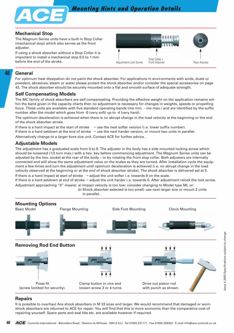
Controls International · Belvedere Road · Newton-le-Willows · WA12 0JJ · Tel 01925 227171 · Fax 01925 229323 · E-mail [email protected]
Mounting Hints and Operation Details
Issu
e 4.
2003
Sp
ecif
icat
ion
s su
bje
ct t
o c
han
ge
46
46
Mechanical StopThe Magnum Series units have a built in Stop Collar (mechanical stop) which also serves as the front adjuster.If using a shock absorber without a Stop Collar it is important to install a mechanical stop 0.5 to 1 mm before the end of the stroke.
Mounting Options
RepairsIt is possible to overhaul Ace shock absorbers in M 33 sizes and larger. We would recommend that damaged or wornshock absorbers are returned to ACE for repair. You will find that this is more economic than the comparative cost of repairing yourself. Spare parts and seal kits etc. are available however if required.
Clamp button in vice andloosen screw 3 or 4 turns.
Stop Collar +Front Adjuster Rear AdusterAdjustment Lock Screw
Press fit(screw loctited for security).
Drive out piston rodwith punch as shown.
GeneralFor optimum heat dissipation do not paint the shock absorber. For applications in environments with acids, dusts orpowders, abrasives, steam or water please protect the shock absorber and/or consider the special accessories on page43. The shock absorber should be securely mounted onto a flat and smooth surface of adequate strength.
Self Compensating ModelsThe MC family of shock absorbers are self compensating. Providing the effective weight on the application remains wit-hin the band given in the capacity charts then no adjustment is necessary for changes in weights, speeds or propellingforce. These units are available with five standard operating bands (me min. – me max.) and are identified by the suffixnumber after the model which goes from -0 (very soft) up to -4 (very hard).The optimum deceleration is achieved when there is no abrupt change in the load velocity at the beginning or the endof the shock absorber stroke.If there is a hard impact at the start of stroke f use the next softer version (i.e. lower suffix number). If there is a hard setdown at the end of stroke f use the next harder version, or mount two units in parallel. Alternatively change to a larger bore size unit. Contact ACE for further advice.
Adjustable ModelsThe adjustment has a graduated scale from 0 to 9. The adjuster in the body has a side mounted locking screw whichshould be loosened (1/2 turn max.) with a hex. key before commencing adjustment. The Magnum Series units can beadjusted by the hex. socket at the rear of the body – or by rotating the front stop collar. Both adjusters are internallyconnected and will show the same adjustment value on the scales as they are turned. After installation cycle the equip-ment a few times and turn the adjustment until optimum deceleration is achieved (i.e. no abrupt change in the load velocity observed at the beginning or at the end of shock absorber stroke). The shock absorber is delivered set at 5.If there is a hard impact at start of stroke f adjust the unit softer i.e. towards 9 on the scale. If there is a hard setdown at end of stroke f adjust the unit harder i.e. towards 0. After adjustment relock the lock screw. Adjustment approaching “0” means: a) Impact velocity is too low: consider changing to Model type ML or:
b) Shock absorber selected is too small: use next larger size or mount 2 units in parallel.
Basic Model Flange Mounting Side Foot Mounting Clevis Mounting
Removing Rod End Button
ACE-Kat_2003_UK_044-049 22.09.2003 17:23 Uhr Seite 46
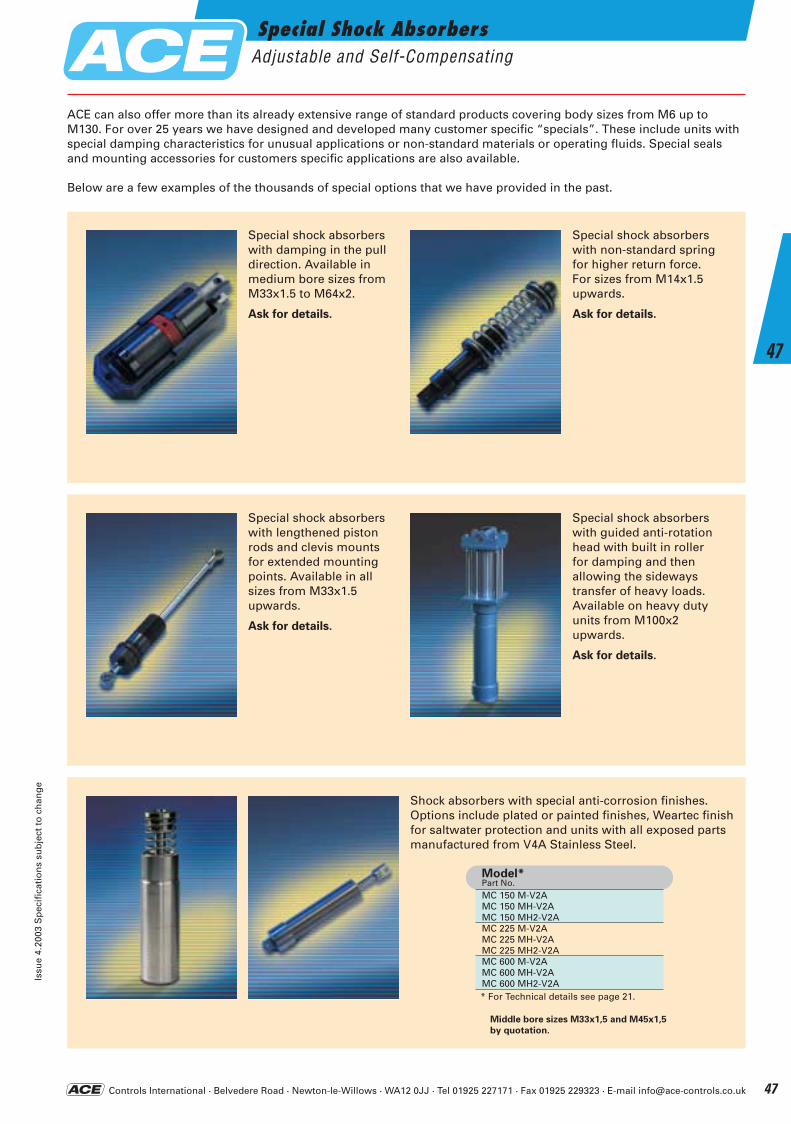
Controls International · Belvedere Road · Newton-le-Willows · WA12 0JJ · Tel 01925 227171 · Fax 01925 229323 · E-mail [email protected]
Special Shock AbsorbersAdjustable and Self-Compensating
Issu
e 4.
2003
Sp
ecif
icat
ion
s su
bje
ct t
o c
han
ge
47
47
ACE can also offer more than its already extensive range of standard products covering body sizes from M6 up toM130. For over 25 years we have designed and developed many customer specific “specials”. These include units withspecial damping characteristics for unusual applications or non-standard materials or operating fluids. Special sealsand mounting accessories for customers specific applications are also available.
Below are a few examples of the thousands of special options that we have provided in the past.
MC 150 M-V2AMC 150 MH-V2AMC 150 MH2-V2AMC 225 M-V2AMC 225 MH-V2AMC 225 MH2-V2AMC 600 M-V2AMC 600 MH-V2AMC 600 MH2-V2A* For Technical details see page 21.
Model*Part No.
Special shock absorbers with damping in the pull direction. Available in medium bore sizes from M33x1.5 to M64x2.
Ask for details.
Special shock absorbers with non-standard spring for higher return force. For sizes from M14x1.5 upwards.
Ask for details.
Special shock absorbers with guided anti-rotation head with built in roller for damping and then allowing the sideways transfer of heavy loads. Available on heavy duty units from M100x2 upwards.
Ask for details.
Special shock absorbers with lengthened piston rods and clevis mounts for extended mountingpoints. Available in all sizes from M33x1.5 upwards.
Ask for details.
Shock absorbers with special anti-corrosion finishes.Options include plated or painted finishes, Weartec finishfor saltwater protection and units with all exposed partsmanufactured from V4A Stainless Steel.
Middle bore sizes M33x1,5 and M45x1,5
by quotation.
ACE-Kat_2003_UK_044-049 22.09.2003 17:23 Uhr Seite 47
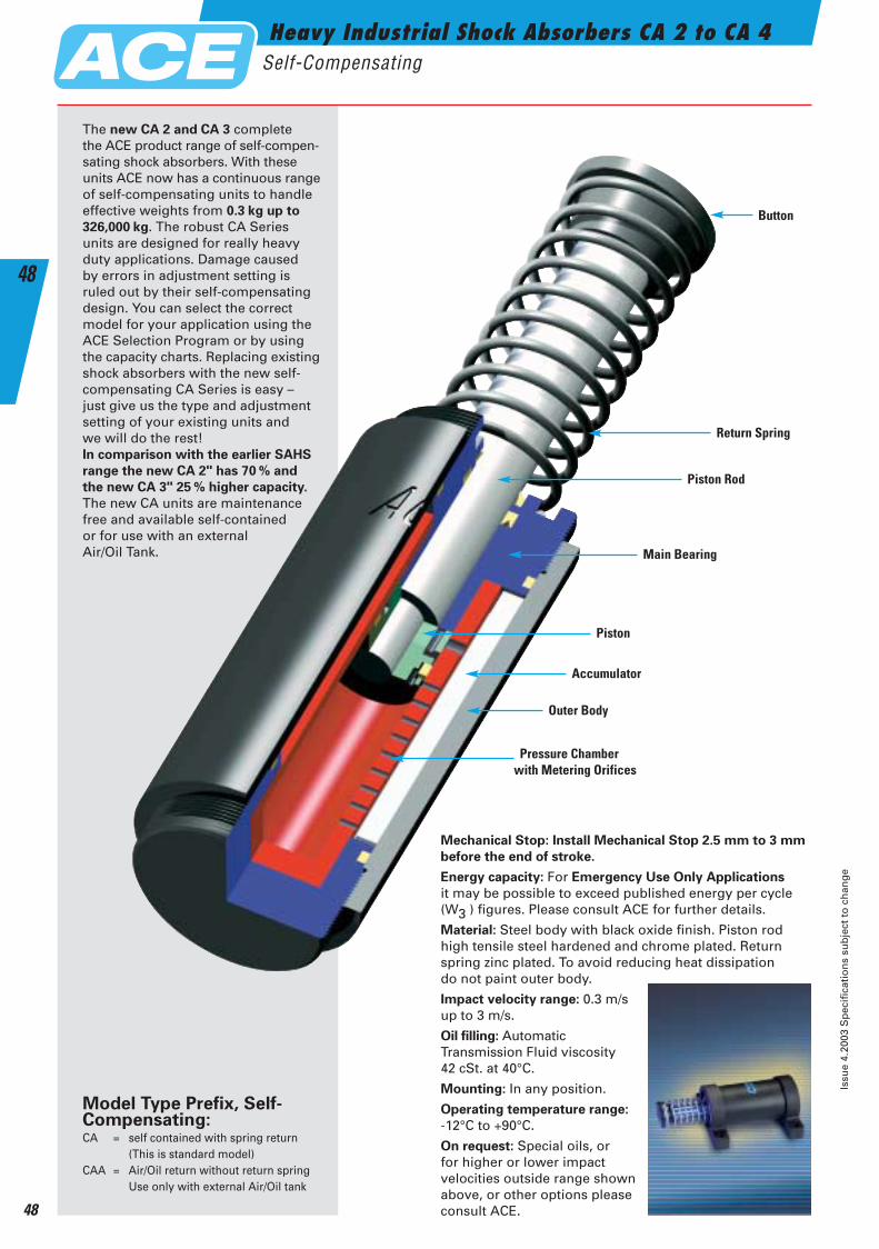
Heavy Industrial Shock Absorbers CA 2 to CA 4Self-Compensating
Issu
e 4.
2003
Sp
ecif
icat
ion
s su
bje
ct t
o c
han
ge
48
48
Mechanical Stop: Install Mechanical Stop 2.5 mm to 3 mm
before the end of stroke.
Energy capacity: For Emergency Use Only Applications
it may be possible to exceed published energy per cycle (W3 ) figures. Please consult ACE for further details.
Material: Steel body with black oxide finish. Piston rodhigh tensile steel hardened and chrome plated. Returnspring zinc plated. To avoid reducing heat dissipation do not paint outer body.
Impact velocity range: 0.3 m/sup to 3 m/s.
Oil filling: AutomaticTransmission Fluid viscosity 42 cSt. at 40°C.
Mounting: In any position.
Operating temperature range:
-12°C to +90°C.
On request: Special oils, or for higher or lower impact velocities outside range shownabove, or other options pleaseconsult ACE.
Button
Return Spring
Piston Rod
Main Bearing
Accumulator
Piston
Pressure Chamberwith Metering Orifices
Outer Body
The new CA 2 and CA 3 complete the ACE product range of self-compen-sating shock absorbers. With theseunits ACE now has a continuous rangeof self-compensating units to handle effective weights from 0.3 kg up to
326,000 kg. The robust CA Seriesunits are designed for really heavyduty applications. Damage caused by errors in adjustment setting is ruled out by their self-compensatingdesign. You can select the correctmodel for your application using theACE Selection Program or by usingthe capacity charts. Replacing existingshock absorbers with the new self-compensating CA Series is easy – just give us the type and adjustmentsetting of your existing units and we will do the rest!In comparison with the earlier SAHS
range the new CA 2" has 70 % and
the new CA 3" 25 % higher capacity.
The new CA units are maintenancefree and available self-contained or for use with an external Air/Oil Tank.
Model Type Prefix, Self-Compensating:CA = self contained with spring return
(This is standard model)CAA = Air/Oil return without return spring
Use only with external Air/Oil tank
ACE-Kat_2003_UK_044-049 22.09.2003 17:24 Uhr Seite 48
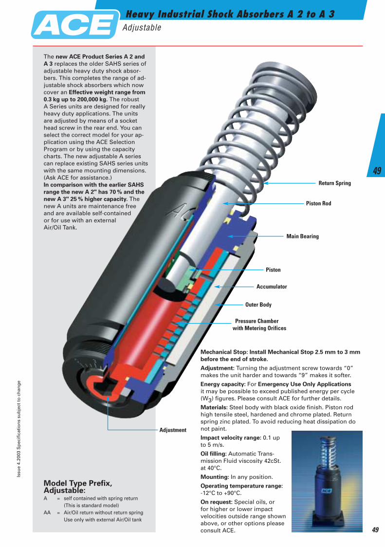
Heavy Industrial Shock Absorbers A 2 to A 3Adjustable
Issu
e 4.
2003
Sp
ecif
icat
ion
s su
bje
ct t
o c
han
ge
49
49
Mechanical Stop: Install Mechanical Stop 2.5 mm to 3 mm
before the end of stroke.
Adjustment: Turning the adjustment screw towards “0”makes the unit harder and towards “9” makes it softer.
Energy capacity: For Emergency Use Only Applications
it may be possible to exceed published energy per cycle (W3) figures. Please consult ACE for further details.
Materials: Steel body with black oxide finish. Piston rod high tensile steel, hardened and chrome plated. Return spring zinc plated. To avoid reducing heat dissipation do not paint.
Impact velocity range: 0.1 up to 5 m/s.
Oil filling: Automatic Trans-mission Fluid viscosity 42cSt. at 40°C.
Mounting: In any position.
Operating temperature range:
-12°C to +90°C.
On request: Special oils, or for higher or lower impact velocities outside range shown above, or other options pleaseconsult ACE.
Return Spring
Piston Rod
Main Bearing
Accumulator
Piston
Pressure Chamberwith Metering Orifices
Outer Body
Adjustment
The new ACE Product Series A 2 and
A 3 replaces the older SAHS series ofadjustable heavy duty shock absor-bers. This completes the range of ad-justable shock absorbers which nowcover an Effective weight range from
0.3 kg up to 200,000 kg. The robust A Series units are designed for reallyheavy duty applications. The unitsare adjusted by means of a sockethead screw in the rear end. You canselect the correct model for your ap-plication using the ACE SelectionProgram or by using the capacitycharts. The new adjustable A seriescan replace existing SAHS series unitswith the same mounting dimensions.(Ask ACE for assistance.) In comparison with the earlier SAHS
range the new A 2" has 70 % and the
new A 3" 25 % higher capacity. Thenew A units are maintenance freeand are available self-contained or for use with an external Air/Oil Tank.
Model Type Prefix, Adjustable:A = self contained with spring return
(This is standard model)AA = Air/Oil return without return spring
Use only with external Air/Oil tank
ACE-Kat_2003_UK_044-049 22.09.2003 17:24 Uhr Seite 49
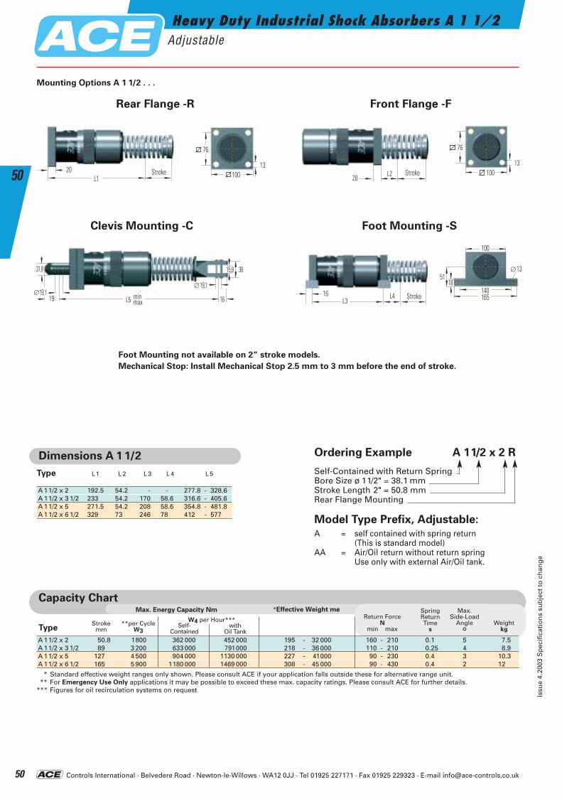
Controls International · Belvedere Road · Newton-le-Willows · WA12 0JJ · Tel 01925 227171 · Fax 01925 229323 · E-mail [email protected]
Heavy Duty Industrial Shock Absorbers A 1 1/2Adjustable
Issu
e 4.
2003
Sp
ecif
icat
ion
s su
bje
ct t
o c
han
ge
50
50
Capacity Chart*Effective Weight meMax. Energy Capacity Nm
W4 per Hour*** **per Cycle W3
Strokemm
Return ForceN
min max
SpringReturnTime
s
Max.Side-Load
Angle
°Weight
kgType
A 11/2 x 2 50.8 1800 362 000 452 000 195 - 32 000 160 - 210 0.1 5 7.5A 11/2 x 3 1/2 89 3 200 633 000 791000 218 - 36 000 110 - 210 0.25 4 8.9A 11/2 x 5 127 4 500 904 000 1130 000 227 - 41000 90 - 230 0.4 3 10.3A 11/2 x 6 1/2 165 5 900 1180 000 1469 000 308 - 45 000 90 - 430 0.4 2 12
* Standard effective weight ranges only shown. Please consult ACE if your application falls outside these for alternative range unit.** For Emergency Use Only applications it may be possible to exceed these max. capacity ratings. Please consult ACE for further details.
*** Figures for oil recirculation systems on request
withOil Tank
Self-Contained
Mounting Options A 1 1/2 . . .
Foot Mounting not available on 2“ stroke models.
Mechanical Stop: Install Mechanical Stop 2.5 mm to 3 mm before the end of stroke.
Rear Flange -R
L120 Hub 100
76
13
Front Flange -F
L220 Hub 100
76
13
Foot Mounting -S
L416 HubL3140
5113
165
18
∅
100
Clevis Mounting -C
31,8
∅19,119
∅19,1
16
15,9 38
L5 minmax
Stroke Stroke
Stroke
Dimensions A 1 1/2
A 11/2 x 2 192.5 54.2 - - 277.8 - 328.6A 11/2 x 3 1/2 233 54.2 170 58.6 316.6 - 405.6A 11/2 x 5 271.5 54.2 208 58.6 354.8 - 481.8A 11/2 x 6 1/2 329 73 246 78 412 - 577
Type L1 L 2 L 3 L 4 L 5
Ordering Example A 11/2 x 2 R
Self-Contained with Return SpringBore Size ø 11/2" = 38.1 mm Stroke Length 2" = 50.8 mm Rear Flange Mounting
Model Type Prefix, Adjustable:
A = self contained with spring return(This is standard model)
AA = Air/Oil return without return springUse only with external Air/Oil tank.
ACE-Kat_2003_UK_050-055 22.09.2003 17:28 Uhr Seite 50
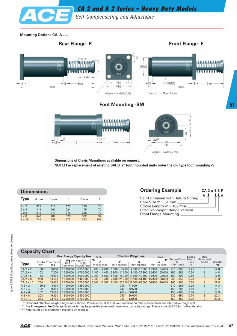
Controls International · Belvedere Road · Newton-le-Willows · WA12 0JJ · Tel 01925 227171 · Fax 01925 229323 · E-mail [email protected]
CA 2 and A 2 Series – Heavy Duty ModelsSelf-Compensating and Adjustable
Issu
e 4.
2003
Sp
ecif
icat
ion
s su
bje
ct t
o c
han
ge
51
51
∅ 35
E
19 19Amax
Bmax
Hub
Capacity Chart*Effective Weight meMax. Energy Capacity Nm
W4 per Hour*****per CycleW3
Strokemm
-1min kg max
-2min kg max
-3min kg max
-4min kg max
Return ForceN
min max
SpringReturnTime
s
Max.Side-Load
Angle
°Weight
kgType
CA 2 x 2 50.8 3 600 1 100 000 1 350 000 700 - 2 200 1 800 - 5 400 4 500 -13 600 11 300 - 34 000 210 - 285 0.25 3 12.8CA 2 x 4 102 7 200 1 350 000 1 700 000 1 400 - 4 400 3 600 -11 000 9 100 -27 200 22 600- 68 000 150 - 285 0.50 3 14.8CA 2 x 6 152 10 800 1 600 000 2 000 000 2 200 - 6 500 5 400 -16 300 13 600 -40 800 34 000-102 000 150 - 400 0.60 3 16.9CA 2 x 8 203 14 500 1 900 000 2 400 000 2 900 - 8 700 7 200 -21 700 18 100 -54 400 45 300-136 000 230 - 650 0.70 3 19.3CA 2 x 10 254 18 000 2 200 000 2 700 000 3 600 -11 000 9 100 -27 200 22 600 -68 000 56 600-170 000 160 - 460 0.80 3 22.8A 2 x 2 50.8 3 600 1 100 000 1 350 000 250 - 77 000 210 - 285 0.25 3 14.3A 2 x 4 102 9 000 1 350 000 1 700 000 230 - 72 500 150 - 285 0.50 3 16.7A 2 x 6 152 13 500 1 600 000 2 000 000 260 - 86 000 150 - 400 0.60 3 19.3A 2 x 8 203 19 200 1 900 000 2 400 000 260 - 90 000 230 - 650 0.70 3 22.3A 2 x 10 254 23 700 2 200 000 2 700 000 320 - 113 000 160 - 460 0.80 3 26.3
* Standard effective weight ranges only shown. Please consult ACE if your application falls outside these for alternative range unit.** For Emergency Use Only applications it may be possible to exceed these max. capacity ratings. Please consult ACE for further details.
*** Figures for oil recirculation systems on request
withAir/Oil Tank
Self-Contained
Soft Hard
Dimensions
A max B max C D max EType
2 x 2 313 110 173 125 702 x 4 414 160 224 175 702 x 6 516 211 275 226 702 x 8 643 287 326 302 922 x 10 745 338 377 353 108
∅ 108 (120)19 19Amax
Bmax
M100x2
32 15DmaxC15
60
6036
160190
18∅
Rear Flange -R Front Flange -F
Foot Mounting -SM
Mounting Options CA, A . . .
Dimensions of Clevis Mountings available on request.
NOTE! For replacement of existing SAHS 2" foot mounted units order the old type foot mounting -S.
111140
17∅
Dims. in ( ) for Model A 2 onlyAdjuster – Model A 2 only
Adjuster – Model A 2 only
Stroke
Ordering Example CA 2 x 4-3 F
Self-Contained with Return SpringBore Size 2" = 51 mm Stroke Length 4" = 102 mm Effective Weight Range Version Front Flange Mounting
ACE-Kat_2003_UK_050-055 22.09.2003 17:28 Uhr Seite 51
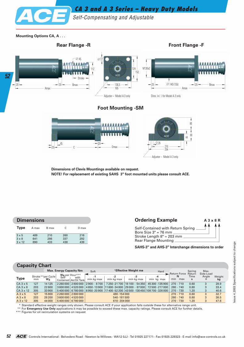
Controls International · Belvedere Road · Newton-le-Willows · WA12 0JJ · Tel 01925 227171 · Fax 01925 229323 · E-mail [email protected]
112
25 25Amax
Bmax
Hub
∅ 45
CA 3 and A 3 Series – Heavy Duty ModelsSelf-Compensating and Adjustable
Issu
e 4.
2003
Sp
ecif
icat
ion
s su
bje
ct t
o c
han
ge
52
52
Dimensions of Clevis Mountings available on request.
NOTE! For replacement of existing SAHS 3" foot mounted units please consult ACE.
136,5165
17∅
124152
∅ 140 (155)25 25Amax
Bmax
M130x2
45 25DmaxC25
80
8044
216254
26∅
Rear Flange -R Front Flange -F
Foot Mounting -SM
max.Achsab-
weichung
°Gewicht
kg
Capacity Chart*Effective Weight meMax. Energy Capacity Nm
W4 per Hour*****per CycleW3
Strokemm
-1min kg max
-2min kg max
-3min kg max
-4min kg max
Return ForceN
min max
SpringReturnTime
sType
CA 3 x 5 127 14 125 2 260 000 2 800 000 2 900 - 8 700 7 250 -21 700 18 100 - 54 350 45 300 -135 900 270 - 710 0.60 3 28.9CA 3 x 8 203 22 600 3 600 000 4 520 000 4 650-13 900 11 600 -34 800 29 000 - 87000 72 500 -217 000 280 - 740 0.80 3 33.4CA 3 x 12 305 33 900 5 400 000 6 780 000 6 950-20 900 17 400 -52 200 43 500 -130450 108 700 -326 000 270 - 730 1.20 3 40.6A 3 x 5 127 15 800 2 260 000 2 800 000 480 -154 000 270 - 710 0.60 3 32.7A 3 x 8 203 28 200 3 600 000 4 520 000 540 -181 500 280 - 740 0.80 3 38.5A 3 x 12 305 44 000 5 400 000 6 780 000 610 -204 000 270 - 730 1.20 3 47.6
* Standard effective weight ranges only shown. Please consult ACE if your application falls outside these for alternative range unit.** For Emergency Use Only applications it may be possible to exceed these max. capacity ratings. Please consult ACE for further details.
*** Figures for oil recirculation systems on request
withAir/Oil Tank
Self-Contained
Soft Hard
Dimensions
A max B max C D maxType
3 x 5 489 210 260 2163 x 8 641 286 337 2923 x 12 890 433 438 439
Max.Side-Load
Angle
°Weight
kg
Mounting Options CA, A . . .
Dims. in ( ) for Model A 3 only
Adjuster – Model A 3 only
Adjuster – Model A 3 only
Stroke
Ordering Example A 3 x 8 R
Self-Contained with Return SpringBore Size 3" = 76 mm Stroke Length 8" = 203 mm Rear Flange Mounting
SAHS-3" and AHS-3" Interchange dimensions to order
ACE-Kat_2003_UK_050-055 22.09.2003 17:28 Uhr Seite 52
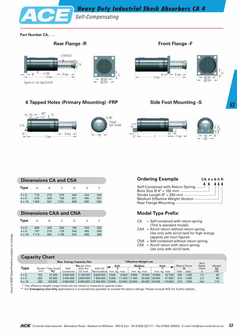
Controls International · Belvedere Road · Newton-le-Willows · WA12 0JJ · Tel 01925 227171 · Fax 01925 229323 · E-mail [email protected]
Dimensions CA and CSA
4 x 6 716 278 678 240 444 2564 x 8 818 329 780 291 495 3074 x 16 1 300 607 1 261 569 698 585
Type A B C D E F
Dimensions CAA and CNA
4 x 6 666 228 628 190 444 2064 x 8 767 278 729 240 495 2564 x 16 1 174 482 1 136 444 698 460
Type A B C D E F
max.Achsab-
weichung
°Gewicht
kg
Capacity Chart*Effective Weight meMax. Energy Capacity Nm
4 x 6 152 47 500 3 000 000 5 100 000 6 600 000 3 500 - 8 600 8 600 - 18 600 18 600 - 42 700 480 - 1 000 1.8 604 x 8 203 63 300 3 400 000 5 600 000 7 300 000 5 000 - 11 400 11 400 - 25 000 25 000 - 57 000 310 - 1 000 2.3 684 x 16 406 126 500 5 600 000 9 600 000 12 400 000 10 000 - 23 000 23 000 - 50 000 50 000 - 115 000 310 - 1 000 Ask 170
* The effective weight range limits can be raised or lowered to special order.** For Emergency Use Only applications it is sometimes possible to exceed the above ratings. Please consult ACE for further details.
RodW4 per Hour Soft Medium Hard Return Force Reset Weight
Type Stroke **per Cycle Self- with Air/ with Oil -3 -5 -7 N Time kgmm W3 Contained Oil Tank Recirculation min kg max min kg max min kg max min max s FRP
Ordering Example CA 4 x 8-5 R
Self-Contained with Return SpringBore Size Ø 4" = 102 mm Stroke Length 8" = 203 mm Medium Effective Weight VersionRear Flange Mounting
Model Type Prefix:
CA = Self-contained with return spring(This is standard model).
CAA = Air/oil return without return springUse only with air/oil tank for high energy capacity per hour figures.
CNA = Self-contained without return spring.CSA = Air/oil return with return spring.
Use only with air/oil tank.
A max
114
54 (63,5)∅
B max38 190∅C max
D max38
∅16
C maxB max
NPT1 1/2''
20
102 10
254
27203
254
27203
114
204165
70
6 x 60°
159
Gewinde5/8''-18 UNF ∅27
E22
22 F max
Rear Flange -R Front Flange -F
Part Number CA, . . .
6 Tapped Holes (Primary Mounting) -FRP Side Foot Mounting -S
Thread5/8"-18 UNF
Figures in ( ) for Type CA 4x16
NPT
Heavy Duty Industrial Shock Absorbers CA 4Self-Compensating
Issu
e 4.
2003
Sp
ecif
icat
ion
s su
bje
ct t
o c
han
ge
53
53
ACE-Kat_2003_UK_050-055 22.09.2003 17:29 Uhr Seite 53
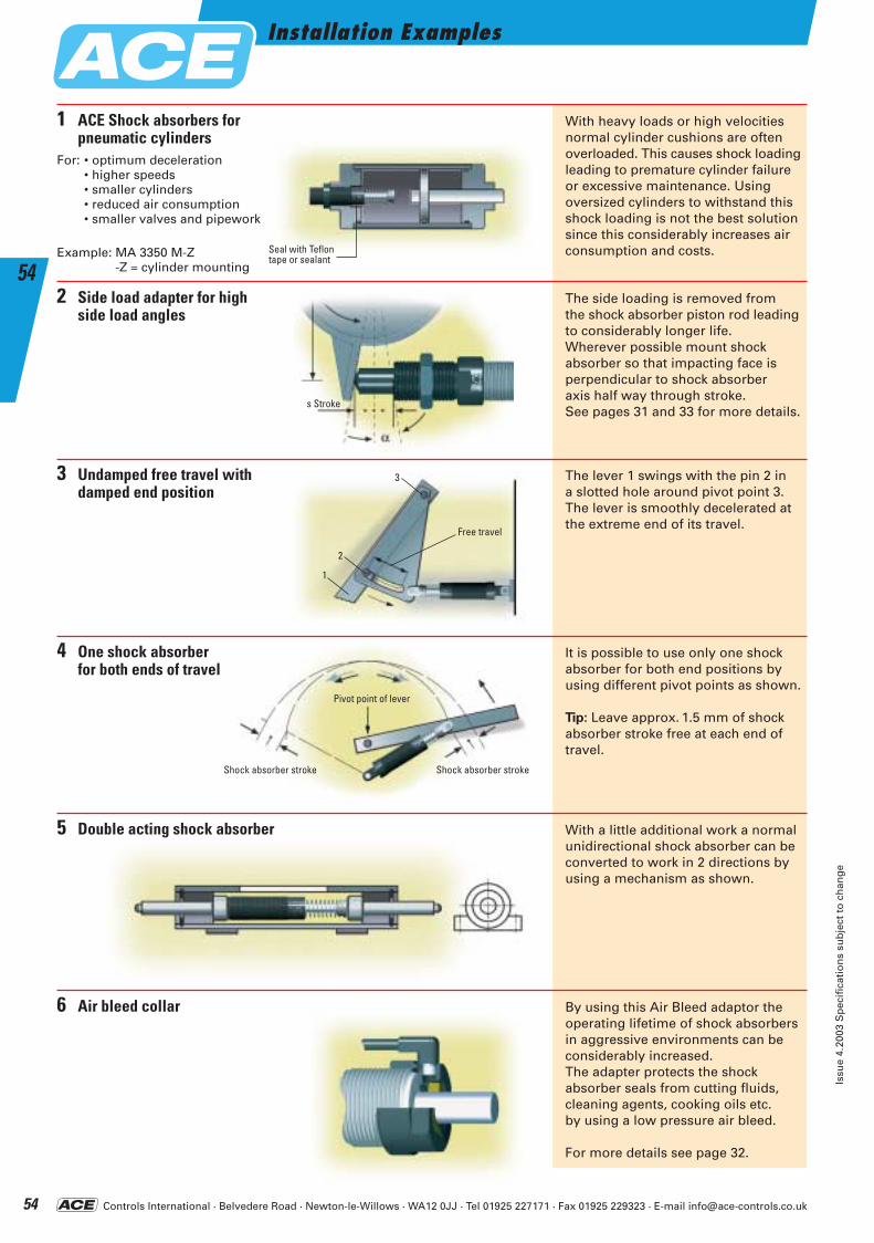
Controls International · Belvedere Road · Newton-le-Willows · WA12 0JJ · Tel 01925 227171 · Fax 01925 229323 · E-mail [email protected]
Shock absorber stroke Shock absorber stroke
Pivot point of lever
With heavy loads or high velocities normal cylinder cushions are often overloaded. This causes shock loading leading to premature cylinder failure or excessive maintenance. Using oversized cylinders to withstand this shock loading is not the best solution since this considerably increases air consumption and costs.
The side loading is removed from the shock absorber piston rod leading to considerably longer life.Wherever possible mount shock absorber so that impacting face is perpendicular to shock absorber axis half way through stroke.See pages 31 and 33 for more details.
1
2
3
4
5
6
ACE Shock absorbers for pneumatic cylinders
For: • optimum deceleration • higher speeds • smaller cylinders • reduced air consumption • smaller valves and pipework
Example: MA 3350 M-Z-Z = cylinder mounting
The lever 1 swings with the pin 2 in a slotted hole around pivot point 3. The lever is smoothly decelerated at the extreme end of its travel.
Undamped free travel withdamped end position
It is possible to use only one shock absorber for both end positions by using different pivot points as shown.
Tip: Leave approx. 1.5 mm of shock absorber stroke free at each end of travel.
With a little additional work a normal unidirectional shock absorber can be converted to work in 2 directions by using a mechanism as shown.
Air bleed collar
Seal with Teflontape or sealant
Double acting shock absorber
Side load adapter for highside load angles
s Stroke
Free travel
1
2
3
By using this Air Bleed adaptor the operating lifetime of shock absorbers in aggressive environments can be considerably increased. The adapter protects the shock absorber seals from cutting fluids, cleaning agents, cooking oils etc. by using a low pressure air bleed.
For more details see page 32.
One shock absorberfor both ends of travel
Installation Examples
Issu
e 4.
2003
Sp
ecif
icat
ion
s su
bje
ct t
o c
han
ge
54
54
ACE-Kat_2003_UK_050-055 22.09.2003 17:29 Uhr Seite 54
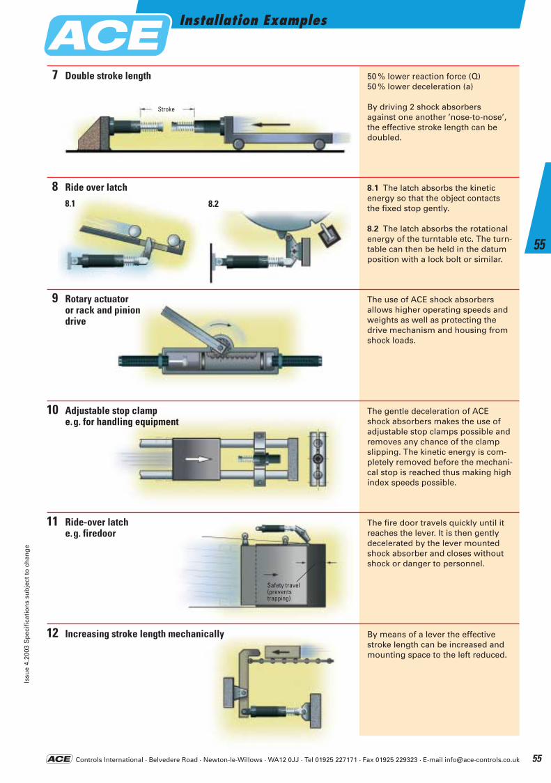
Controls International · Belvedere Road · Newton-le-Willows · WA12 0JJ · Tel 01925 227171 · Fax 01925 229323 · E-mail [email protected]
Stroke
8.1 The latch absorbs the kinetic energy so that the object contacts the fixed stop gently.
8.2 The latch absorbs the rotational energy of the turntable etc. The turn-table can then be held in the datum position with a lock bolt or similar.
Increasing stroke length mechanically
The fire door travels quickly until itreaches the lever. It is then gentlydecelerated by the lever mountedshock absorber and closes withoutshock or danger to personnel.
The use of ACE shock absorbers allows higher operating speeds andweights as well as protecting the drive mechanism and housing from shock loads.
The gentle deceleration of ACE shock absorbers makes the use of adjustable stop clamps possible and removes any chance of the clamp slipping. The kinetic energy is com-pletely removed before the mechani-cal stop is reached thus making highindex speeds possible.
Rotary actuatoror rack and piniondrive
Adjustable stop clampe.g. for handling equipment
By means of a lever the effectivestroke length can be increased andmounting space to the left reduced.
Ride-over latche.g. firedoor
Ride over latch8
9
10
11
12
50 % lower reaction force (Q)50 % lower deceleration (a)
By driving 2 shock absorbers against one another ’nose-to-nose’,the effective stroke length can be doubled.
Double stroke length7
8.1 8.2
Safety travel(prevents trapping)
Installation ExamplesIs
sue
4.20
03 S
pec
ific
atio
ns
sub
ject
to
ch
ang
e
55
55
ACE-Kat_2003_UK_050-055 22.09.2003 17:29 Uhr Seite 55
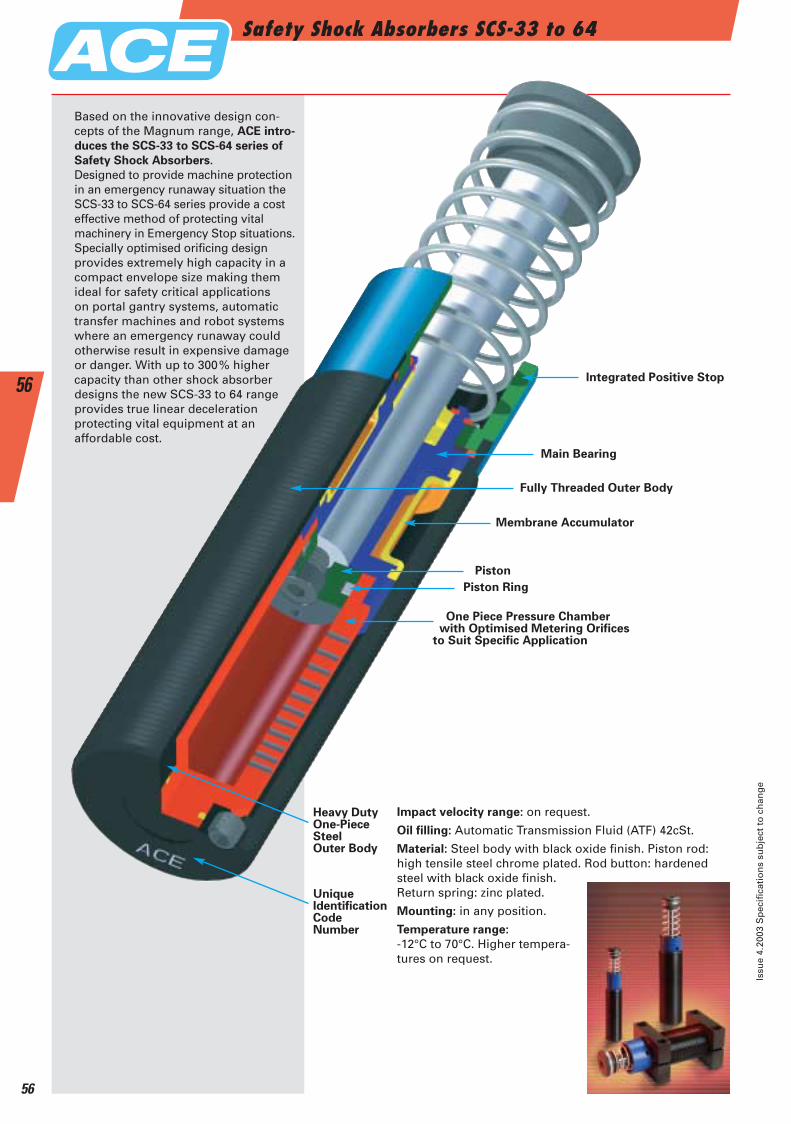
Safety Shock Absorbers SCS-33 to 64
Issu
e 4.
2003
Sp
ecif
icat
ion
s su
bje
ct t
o c
han
ge
56
56
Based on the innovative design con-cepts of the Magnum range, ACE intro-
duces the SCS-33 to SCS-64 series of
Safety Shock Absorbers.Designed to provide machine protectionin an emergency runaway situation theSCS-33 to SCS-64 series provide a costeffective method of protecting vital machinery in Emergency Stop situations.Specially optimised orificing designprovides extremely high capacity in a compact envelope size making themideal for safety critical applications on portal gantry systems, automatic transfer machines and robot systems where an emergency runaway could otherwise result in expensive damage or danger. With up to 300% higher capacity than other shock absorber designs the new SCS-33 to 64 range provides true linear deceleration protecting vital equipment at an affordable cost.
Integrated Positive Stop
Main Bearing
Fully Threaded Outer Body
Piston
Piston Ring
One Piece Pressure Chamber with Optimised Metering Orifices
to Suit Specific Application
Membrane Accumulator
Impact velocity range: on request.
Oil filling: Automatic Transmission Fluid (ATF) 42cSt.
Material: Steel body with black oxide finish. Piston rod: high tensile steel chrome plated. Rod button: hardened steel with black oxide finish. Return spring: zinc plated.
Mounting: in any position.
Temperature range:
-12°C to 70°C. Higher tempera-tures on request.
Heavy DutyOne-PieceSteelOuter Body
UniqueIdentificationCodeNumber
ACE-Kat_2003_UK_056-061 22.09.2003 17:31 Uhr Seite 56
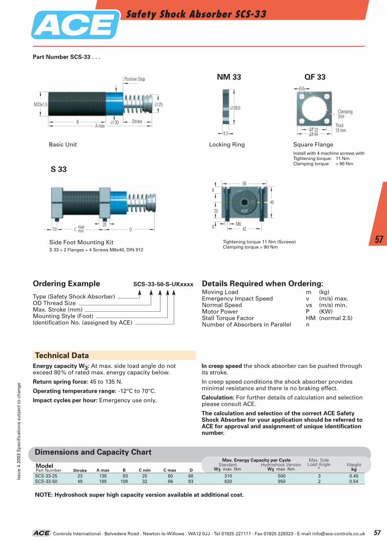
Controls International · Belvedere Road · Newton-le-Willows · WA12 0JJ · Tel 01925 227171 · Fax 01925 229323 · E-mail [email protected]
Safety Shock Absorber SCS-33Is
sue
4.20
03 S
pec
ific
atio
ns
sub
ject
to
ch
ang
e
57
57
M33x1,5
Anschlag
Hub∅ 30
∅ 25
BA max
C D1020max
minM6
42
56
20
40
8
8
S 33
Side Foot Mounting KitS 33 = 2 Flanges + 4 Screws M6x40, DIN 912
Tightening torque 11 Nm (Screws)Clamping torque > 90 Nm
6,5
∅39,6
44
Breite10 mm
Klemm-schlitz
32
6,6
NM 33 QF 33
Locking Ring Square FlangeInstall with 4 machine screws with Tightening torque: 11 NmClamping torque: > 90 Nm
Part Number SCS-33 . . .
Dimensions and Capacity Chart
A max B C min C maxStrokeModelPart NumberSCS-33-25 23 138 83 25 60 68 310 500 3 0.45SCS-33-50 49 189 108 32 86 93 620 950 2 0.54
NOTE: Hydroshock super high capacity version available at additional cost.
Max. Energy Capacity per CycleStandard Hydroshock Version
W3 max Nm W3 max Nm
Max. SideLoad Angle
°Weight
kgD
Ordering Example SCS-33-50-S-UKxxxx
Type (Safety Shock Absorber)OD Thread SizeMax. Stroke (mm)Mounting Style (Foot)Identification No. (assigned by ACE)
Details Required when Ordering:Moving Load m (kg)Emergency Impact Speed v (m/s) max.Normal Speed vs (m/s) min.Motor Power P (KW)Stall Torque Factor HM (normal 2.5)Number of Absorbers in Parallel n
Technical Data
Energy capacity W3: At max. side load angle do not exceed 80% of rated max. energy capacity below.
Return spring force: 45 to 135 N.
Operating temperature range: -12°C to 70°C.
Impact cycles per hour: Emergency use only.
In creep speed the shock absorber can be pushed throughits stroke.
In creep speed conditions the shock absorber provides minimal resistance and there is no braking effect.
Calculation: For further details of calculation and selectionplease consult ACE.
The calculation and selection of the correct ACE SafetyShock Absorber for your application should be referred toACE for approval and assignment of unique identificationnumber.
Basic Unit
Stroke
Positive Stop
ClampingSlot
Thick10 mm
ACE-Kat_2003_UK_056-061 22.09.2003 17:32 Uhr Seite 57
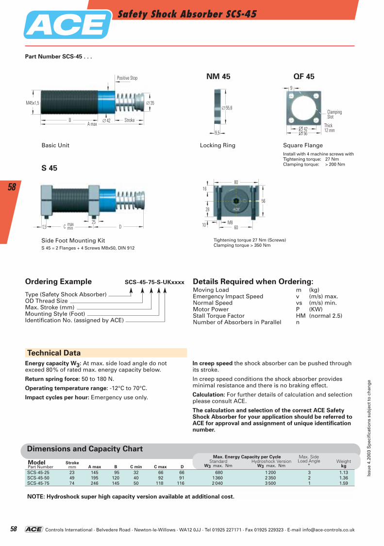
Controls International · Belvedere Road · Newton-le-Willows · WA12 0JJ · Tel 01925 227171 · Fax 01925 229323 · E-mail [email protected]
Safety Shock Absorber SCS-45
Issu
e 4.
2003
Sp
ecif
icat
ion
s su
bje
ct t
o c
han
ge
58
58
M45x1,5
Anschlag
Hub∅ 42
∅ 35
BA max
C D12,525max
minM8
60
80
28
56
10
16
S 45
Side Foot Mounting KitS 45 = 2 Flanges + 4 Screws M8x50, DIN 912
Tightening torque 27 Nm (Screws)Clamping torque > 350 Nm
9,5
∅55,6
56
Breite12 mm
Klemm-schlitz
42
9
NM 45 QF 45
Square FlangeLocking RingInstall with 4 machine screws with Tightening torque: 27 NmClamping torque: > 200 Nm
Dimensions and Capacity Chart
A max B C min C maxStroke
mmModelPart NumberSCS-45-25 23 145 95 32 66 66 680 1 200 3 1.13SCS-45-50 49 195 120 40 92 91 1360 2 350 2 1.36SCS-45-75 74 246 145 50 118 116 2 040 3 500 1 1.59
NOTE: Hydroshock super high capacity version available at additional cost.
Max. Energy Capacity per CycleStandard Hydroshock Version
W3 max. Nm W3 max. Nm
Max. SideLoad Angle
°Weight
kg
Part Number SCS-45 . . .
D
Ordering Example SCS-45-75-S-UKxxxx
Type (Safety Shock Absorber)OD Thread SizeMax. Stroke (mm)Mounting Style (Foot)Identification No. (assigned by ACE)
Details Required when Ordering:Moving Load m (kg)Emergency Impact Speed v (m/s) max.Normal Speed vs (m/s) min.Motor Power P (KW)Stall Torque Factor HM (normal 2.5)Number of Absorbers in Parallel n
Technical Data
Energy capacity W3: At max. side load angle do not exceed 80% of rated max. energy capacity below.
Return spring force: 50 to 180 N.
Operating temperature range: -12°C to 70°C.
Impact cycles per hour: Emergency use only.
In creep speed the shock absorber can be pushed throughits stroke.
In creep speed conditions the shock absorber provides minimal resistance and there is no braking effect.
Calculation: For further details of calculation and selectionplease consult ACE.
The calculation and selection of the correct ACE SafetyShock Absorber for your application should be referred toACE for approval and assignment of unique identificationnumber.
Basic Unit
Stroke
Positive Stop
ClampingSlot
Thick12 mm
ACE-Kat_2003_UK_056-061 22.09.2003 17:32 Uhr Seite 58
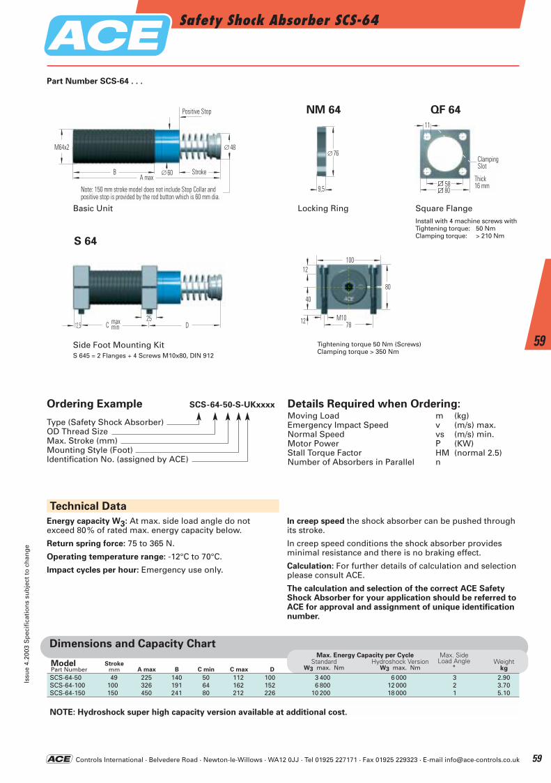
Controls International · Belvedere Road · Newton-le-Willows · WA12 0JJ · Tel 01925 227171 · Fax 01925 229323 · E-mail [email protected]
Safety Shock Absorber SCS-64Is
sue
4.20
03 S
pec
ific
atio
ns
sub
ject
to
ch
ang
e
59
59
M64x2
Anschlag
Hub∅ 60
∅ 48
BA max
Bei einem Hub von 150 mm entfällt die Anschlaghülse.Festanschlag durch Aufprallkopf (60 mm) realisiert.
C D12,525max
minM10
78
100
40
80
12
12
S 64
Side Foot Mounting KitS 645 = 2 Flanges + 4 Screws M10x80, DIN 912
Tightening torque 50 Nm (Screws)Clamping torque > 350 Nm
9,5
∅76
80
Breite16 mm
Klemm-schlitz
58
11
NM 64 QF 64
Locking Ring Square FlangeInstall with 4 machine screws with Tightening torque: 50 NmClamping torque: > 210 Nm
Part Number SCS-64 . . .
Ordering Example SCS-64-50-S-UKxxxx
Type (Safety Shock Absorber)OD Thread SizeMax. Stroke (mm)Mounting Style (Foot)Identification No. (assigned by ACE)
Details Required when Ordering:Moving Load m (kg)Emergency Impact Speed v (m/s) max.Normal Speed vs (m/s) min.Motor Power P (KW)Stall Torque Factor HM (normal 2.5)Number of Absorbers in Parallel n
Technical Data
Energy capacity W3: At max. side load angle do not exceed 80% of rated max. energy capacity below.
Return spring force: 75 to 365 N.
Operating temperature range: -12°C to 70°C.
Impact cycles per hour: Emergency use only.
In creep speed the shock absorber can be pushed throughits stroke.
In creep speed conditions the shock absorber provides minimal resistance and there is no braking effect.
Calculation: For further details of calculation and selectionplease consult ACE.
The calculation and selection of the correct ACE SafetyShock Absorber for your application should be referred toACE for approval and assignment of unique identificationnumber.
Dimensions and Capacity Chart
A max B C min C maxStroke
mmModelPart NumberSCS-64-50 49 225 140 50 112 100 3 400 6 000 3 2.90SCS-64-100 100 326 191 64 162 152 6 800 12 000 2 3.70SCS-64-150 150 450 241 80 212 226 10 200 18 000 1 5.10
NOTE: Hydroshock super high capacity version available at additional cost.
Max. Energy Capacity per CycleStandard Hydroshock Version
W3 max. Nm W3 max. Nm
Max. SideLoad Angle
°Weight
kgD
Basic Unit
Stroke
Positive Stop
Note: 150 mm stroke model does not include Stop Collar and positive stop is provided by the rod button which is 60 mm dia.
ClampingSlot
Thick16 mm
ACE-Kat_2003_UK_056-061 22.09.2003 17:32 Uhr Seite 59
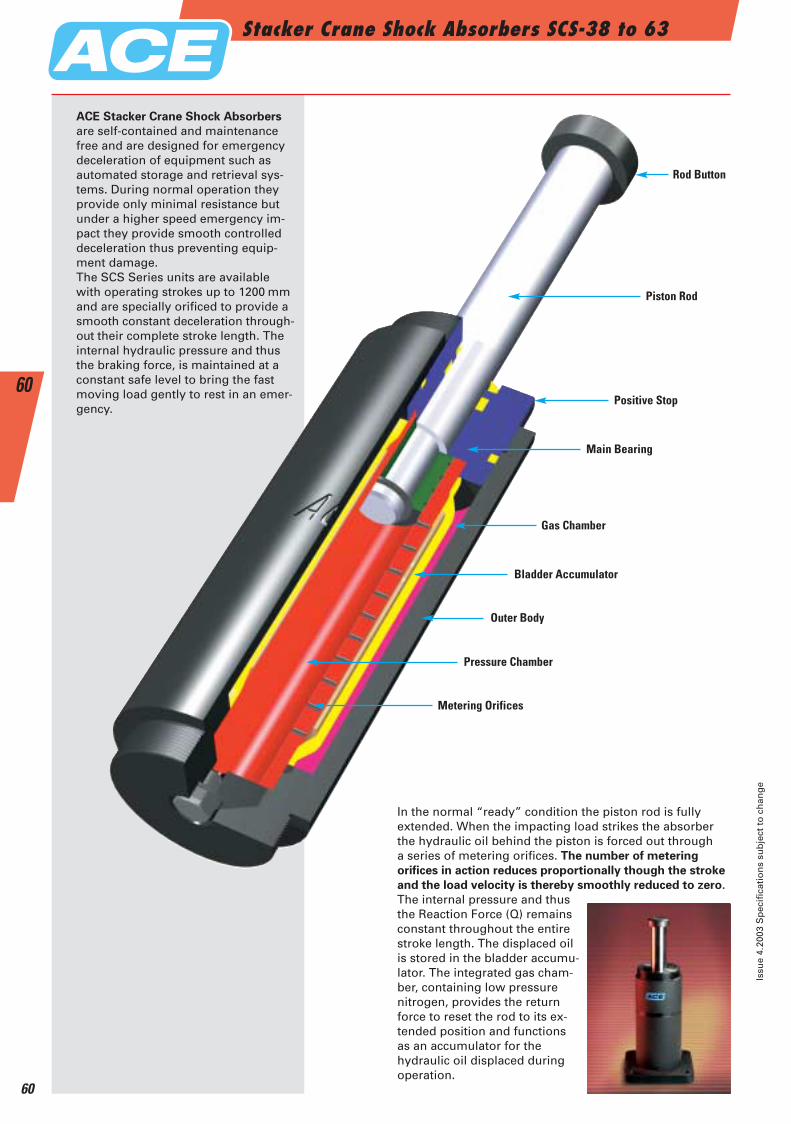
Stacker Crane Shock Absorbers SCS-38 to 63
Issu
e 4.
2003
Sp
ecif
icat
ion
s su
bje
ct t
o c
han
ge
60
60
In the normal “ready” condition the piston rod is fully extended. When the impacting load strikes the absorber the hydraulic oil behind the piston is forced out through a series of metering orifices. The number of metering
orifices in action reduces proportionally though the stroke
and the load velocity is thereby smoothly reduced to zero.
The internal pressure and thusthe Reaction Force (Q) remainsconstant throughout the entirestroke length. The displaced oilis stored in the bladder accumu-lator. The integrated gas cham-ber, containing low pressure nitrogen, provides the returnforce to reset the rod to its ex-tended position and functionsas an accumulator for the hydraulic oil displaced duringoperation.
Rod Button
Piston Rod
Positive Stop
Main Bearing
Gas Chamber
Bladder Accumulator
Metering Orifices
Pressure Chamber
Outer Body
ACE Stacker Crane Shock Absorbers
are self-contained and maintenance free and are designed for emergency deceleration of equipment such as automated storage and retrieval sys-tems. During normal operation they provide only minimal resistance but under a higher speed emergency im-pact they provide smooth controlleddeceleration thus preventing equip-ment damage.The SCS Series units are available with operating strokes up to 1200 mm and are specially orificed to provide asmooth constant deceleration through-out their complete stroke length. The internal hydraulic pressure and thus the braking force, is maintained at a constant safe level to bring the fast moving load gently to rest in an emer-gency.
ACE-Kat_2003_UK_056-061 22.09.2003 17:32 Uhr Seite 60
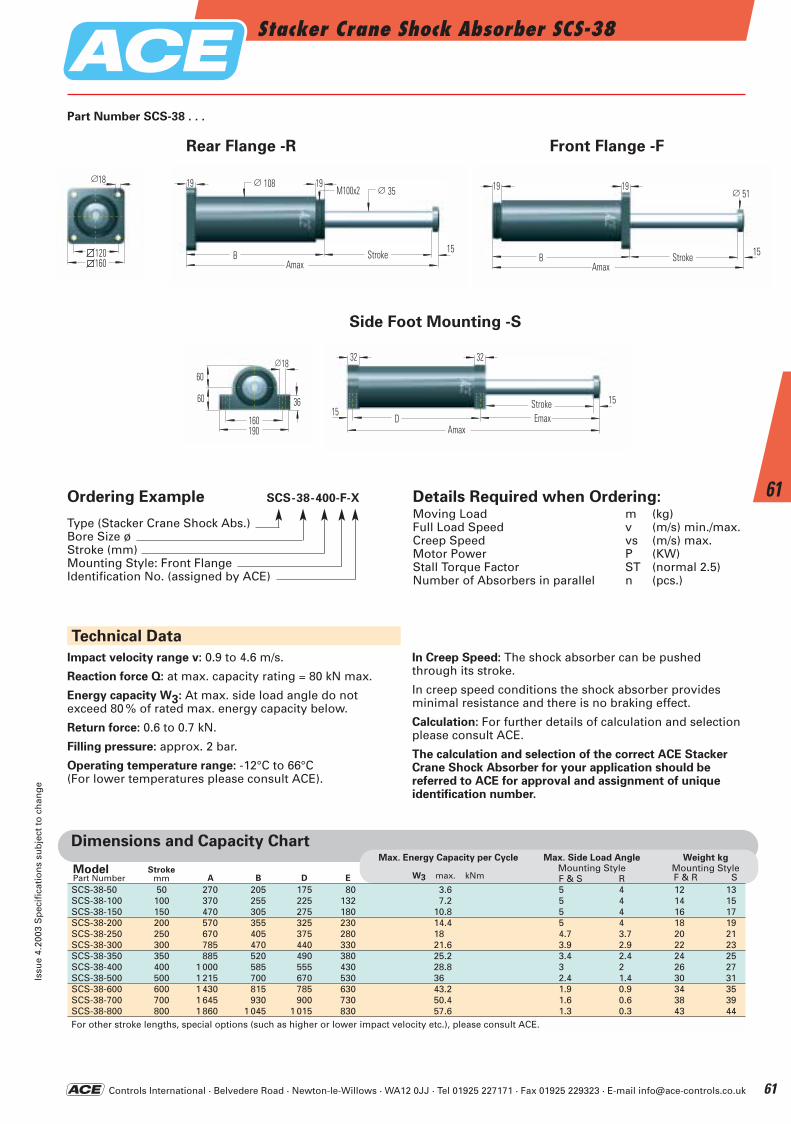
Controls International · Belvedere Road · Newton-le-Willows · WA12 0JJ · Tel 01925 227171 · Fax 01925 229323 · E-mail [email protected]
Stacker Crane Shock Absorber SCS-38Is
sue
4.20
03 S
pec
ific
atio
ns
sub
ject
to
ch
ang
e
61
61
60
60 36
160190
18∅32
Amax
15
32
HubEmaxD
15
∅ 3519
B HubAmax
15
19∅ 108M100x2 19
B HubAmax
15
19∅ 51
120160
18∅
Ordering Example SCS-38-400-F-X
Type (Stacker Crane Shock Abs.)Bore Size øStroke (mm)Mounting Style: Front FlangeIdentification No. (assigned by ACE)
Details Required when Ordering:Moving Load m (kg)Full Load Speed v (m/s) min./max.Creep Speed vs (m/s) max.Motor Power P (KW)Stall Torque Factor ST (normal 2.5)Number of Absorbers in parallel n (pcs.)
Technical Data
Rear Flange -R
Side Foot Mounting -S
Front Flange -F
Part Number SCS-38 . . .
Impact velocity range v: 0.9 to 4.6 m/s.
Reaction force Q: at max. capacity rating = 80 kN max.
Energy capacity W3: At max. side load angle do not exceed 80 % of rated max. energy capacity below.
Return force: 0.6 to 0.7 kN.
Filling pressure: approx. 2 bar.
Operating temperature range: -12°C to 66°C (For lower temperatures please consult ACE).
In Creep Speed: The shock absorber can be pushedthrough its stroke.
In creep speed conditions the shock absorber provides minimal resistance and there is no braking effect.
Calculation: For further details of calculation and selectionplease consult ACE.
The calculation and selection of the correct ACE StackerCrane Shock Absorber for your application should be referred to ACE for approval and assignment of unique identification number.
Stroke Stroke
Stroke
Dimensions and Capacity Chart
A B D EStroke
mmModelPart NumberSCS-38-50 50 270 205 175 80 3.6 5 4 12 13SCS-38-100 100 370 255 225 132 7.2 5 4 14 15SCS-38-150 150 470 305 275 180 10.8 5 4 16 17SCS-38-200 200 570 355 325 230 14.4 5 4 18 19SCS-38-250 250 670 405 375 280 18 4.7 3.7 20 21SCS-38-300 300 785 470 440 330 21.6 3.9 2.9 22 23SCS-38-350 350 885 520 490 380 25.2 3.4 2.4 24 25SCS-38-400 400 1 000 585 555 430 28.8 3 2 26 27SCS-38-500 500 1 215 700 670 530 36 2.4 1.4 30 31SCS-38-600 600 1 430 815 785 630 43.2 1.9 0.9 34 35SCS-38-700 700 1 645 930 900 730 50.4 1.6 0.6 38 39SCS-38-800 800 1 860 1 045 1 015 830 57.6 1.3 0.3 43 44For other stroke lengths, special options (such as higher or lower impact velocity etc.), please consult ACE.
Max. Energy Capacity per Cycle
W3 max. kNm
Max. Side Load AngleMounting StyleF & S R
Weight kgMounting StyleF & R S
ACE-Kat_2003_UK_056-061 22.09.2003 17:33 Uhr Seite 61
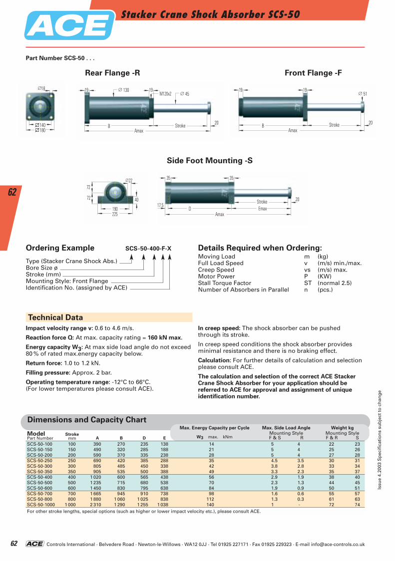
Controls International · Belvedere Road · Newton-le-Willows · WA12 0JJ · Tel 01925 227171 · Fax 01925 229323 · E-mail [email protected]
Stacker Crane Shock Absorber SCS-50
Issu
e 4.
2003
Sp
ecif
icat
ion
s su
bje
ct t
o c
han
ge
62
62
Technical Data
Rear Flange -R Front Flange -F
72
72 40
190225
22∅ 35
Amax
20
35
HubEmaxD
17,5
∅ 4519
B HubAmax
20
19∅ 130M120x2
19
B HubAmax
20
19∅ 51
140180
18∅
Part Number SCS-50 . . .
Ordering Example SCS-50-400-F-X
Type (Stacker Crane Shock Abs.)Bore Size øStroke (mm)Mounting Style: Front FlangeIdentification No. (assigned by ACE)
Details Required when Ordering:Moving Load m (kg)Full Load Speed v (m/s) min./max.Creep Speed vs (m/s) max.Motor Power P (KW)Stall Torque Factor ST (normal 2.5)Number of Absorbers in Parallel n (pcs.)
Side Foot Mounting -S
Impact velocity range v: 0.6 to 4.6 m/s.
Reaction force Q: At max. capacity rating = 160 kN max.
Energy capacity W3: At max side load angle do not exceed80 % of rated max.energy capacity below.
Return force: 1.0 to 1.2 kN.
Filling pressure: Approx. 2 bar.
Operating temperature range: -12°C to 66°C.(For lower temperatures please consult ACE).
In creep speed: The shock absorber can be pushed through its stroke.
In creep speed conditions the shock absorber provides minimal resistance and there is no braking effect.
Calculation: For further details of calculation and selectionplease consult ACE.
The calculation and selection of the correct ACE Stacker Crane Shock Absorber for your application should be referred to ACE for approval and assignment of unique identification number.
Stroke Stroke
Stroke
Dimensions and Capacity Chart
SCS-50-100 100 390 270 235 138 14 5 4 22 23SCS-50-150 150 490 320 285 188 21 5 4 25 26SCS-50-200 200 590 370 335 238 28 5 4 27 28SCS-50-250 250 690 420 385 288 35 4.5 3.5 30 31SCS-50-300 300 805 485 450 338 42 3.8 2.8 33 34SCS-50-350 350 905 535 500 388 49 3.3 2.3 35 37SCS-50-400 400 1 020 600 565 438 56 2.9 1.9 38 40SCS-50-500 500 1 235 715 680 538 70 2.3 1.3 44 45SCS-50-600 600 1 450 830 795 638 84 1.9 0.9 50 51SCS-50-700 700 1 665 945 910 738 98 1.6 0.6 55 57SCS-50-800 800 1 880 1 060 1 025 838 112 1.3 0.3 61 63SCS-50-1000 1 000 2 310 1 290 1 255 1 038 140 1 - 72 74For other stroke lengths, special options (such as higher or lower impact velocity etc.), please consult ACE.
A B D EStroke
mmModelPart Number
Max. Energy Capacity per Cycle
W3 max. kNm
Max. Side Load AngleMounting StyleF & S R
Weight kgMounting StyleF & R S
ACE-Kat_2003_UK_062-067 22.09.2003 17:35 Uhr Seite 62
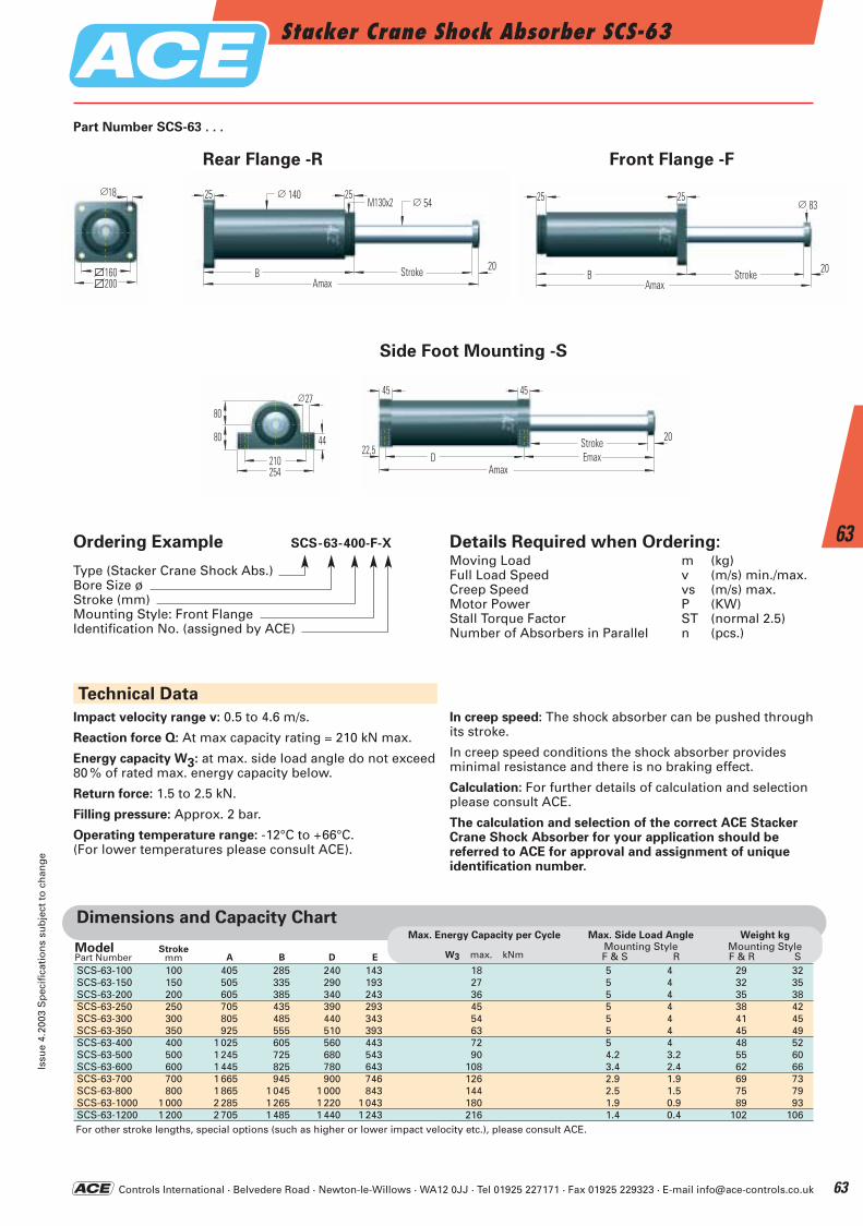
Controls International · Belvedere Road · Newton-le-Willows · WA12 0JJ · Tel 01925 227171 · Fax 01925 229323 · E-mail [email protected]
Stacker Crane Shock Absorber SCS-63Is
sue
4.20
03 S
pec
ific
atio
ns
sub
ject
to
ch
ang
e
63
63
80
80 44
210254
27∅45
Amax
20
45
HubEmaxD
22,5
∅ 5425
B HubAmax
20
25∅ 140M130x2 25
B HubAmax
20
25∅ 83
160200
18∅
Technical Data
Rear Flange -R Front Flange -F
Part Number SCS-63 . . .
Ordering Example SCS-63-400-F-X
Type (Stacker Crane Shock Abs.)Bore Size ø Stroke (mm)Mounting Style: Front FlangeIdentification No. (assigned by ACE)
Details Required when Ordering:Moving Load m (kg)Full Load Speed v (m/s) min./max.Creep Speed vs (m/s) max.Motor Power P (KW)Stall Torque Factor ST (normal 2.5)Number of Absorbers in Parallel n (pcs.)
Side Foot Mounting -S
Impact velocity range v: 0.5 to 4.6 m/s.
Reaction force Q: At max capacity rating = 210 kN max.
Energy capacity W3: at max. side load angle do not exceed80 % of rated max. energy capacity below.
Return force: 1.5 to 2.5 kN.
Filling pressure: Approx. 2 bar.
Operating temperature range: -12°C to +66°C.(For lower temperatures please consult ACE).
In creep speed: The shock absorber can be pushed throughits stroke.
In creep speed conditions the shock absorber provides minimal resistance and there is no braking effect.
Calculation: For further details of calculation and selectionplease consult ACE.
The calculation and selection of the correct ACE Stacker Crane Shock Absorber for your application should be referred to ACE for approval and assignment of unique identification number.
Stroke Stroke
Stroke
Dimensions and Capacity Chart
SCS-63-100 100 405 285 240 143 18 5 4 29 32SCS-63-150 150 505 335 290 193 27 5 4 32 35SCS-63-200 200 605 385 340 243 36 5 4 35 38SCS-63-250 250 705 435 390 293 45 5 4 38 42SCS-63-300 300 805 485 440 343 54 5 4 41 45SCS-63-350 350 925 555 510 393 63 5 4 45 49SCS-63-400 400 1 025 605 560 443 72 5 4 48 52SCS-63-500 500 1 245 725 680 543 90 4.2 3.2 55 60SCS-63-600 600 1 445 825 780 643 108 3.4 2.4 62 66SCS-63-700 700 1 665 945 900 746 126 2.9 1.9 69 73SCS-63-800 800 1 865 1 045 1 000 843 144 2.5 1.5 75 79SCS-63-1000 1 000 2 285 1 265 1 220 1 043 180 1.9 0.9 89 93SCS-63-1200 1 200 2 705 1 485 1 440 1 243 216 1.4 0.4 102 106For other stroke lengths, special options (such as higher or lower impact velocity etc.), please consult ACE.
A B D EStroke
mmModelPart Number
Max. Energy Capacity per Cycle
W3 max. kNm
Max. Side Load AngleMounting StyleF & S R
Weight kgMounting StyleF & R S
ACE-Kat_2003_UK_062-067 22.09.2003 17:36 Uhr Seite 63
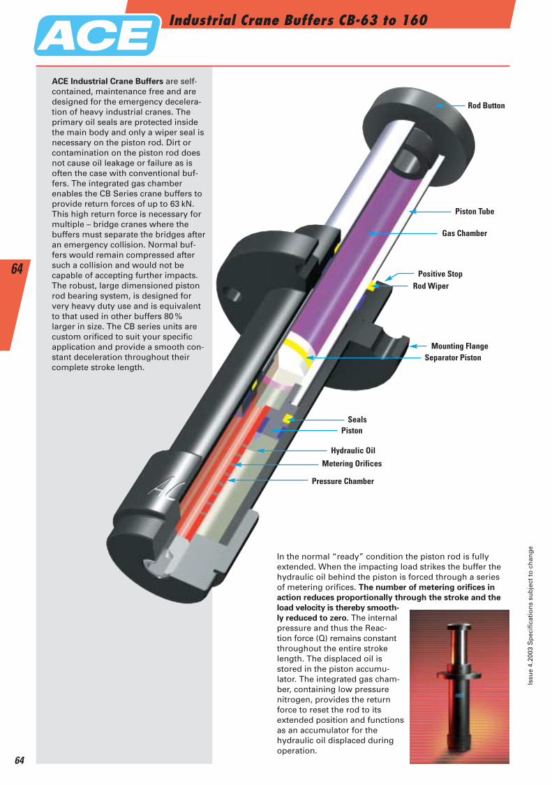
Industrial Crane Buffers CB-63 to 160
Issu
e 4.
2003
Sp
ecif
icat
ion
s su
bje
ct t
o c
han
ge
64
64
ACE Industrial Crane Buffers are self-contained, maintenance free and aredesigned for the emergency decelera-tion of heavy industrial cranes. Theprimary oil seals are protected insidethe main body and only a wiper seal isnecessary on the piston rod. Dirt orcontamination on the piston rod doesnot cause oil leakage or failure as is often the case with conventional buf-fers. The integrated gas chamber enables the CB Series crane buffers to provide return forces of up to 63 kN.This high return force is necessary formultiple – bridge cranes where thebuffers must separate the bridges afteran emergency collision. Normal buf-fers would remain compressed aftersuch a collision and would not be capable of accepting further impacts.The robust, large dimensioned pistonrod bearing system, is designed forvery heavy duty use and is equivalentto that used in other buffers 80 % larger in size. The CB series units are custom orificed to suit your specific application and provide a smooth con-stant deceleration throughout their complete stroke length.
In the normal “ready” condition the piston rod is fully extended. When the impacting load strikes the buffer the hydraulic oil behind the piston is forced through a series of metering orifices. The number of metering orifices in
action reduces proportionally through the stroke and the
load velocity is thereby smooth-
ly reduced to zero. The internalpressure and thus the Reac-tion force (Q) remains constantthroughout the entire strokelength. The displaced oil is stored in the piston accumu-lator. The integrated gas cham-ber, containing low pressure nitrogen, provides the returnforce to reset the rod to its extended position and functionsas an accumulator for the hydraulic oil displaced duringoperation.
Rod Button
Piston Tube
Gas Chamber
Positive StopRod Wiper
Mounting FlangeSeparator Piston
Seals
Hydraulic Oil
Metering Orifices
Pressure Chamber
Piston
ACE-Kat_2003_UK_062-067 22.09.2003 17:36 Uhr Seite 64
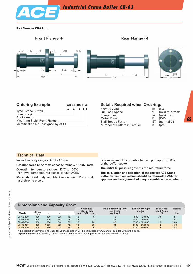
Controls International · Belvedere Road · Newton-le-Willows · WA12 0JJ · Tel 01925 227171 · Fax 01925 229323 · E-mail [email protected]
Industrial Crane Buffer CB-63Is
sue
4.20
03 S
pec
ific
atio
ns
sub
ject
to
ch
ang
e
65
65
Technical Data
Front Flange -F Rear Flange -R
A B C
CB-63-100 100 420 288 192 1.5 16 16 900 - 128 000 3.5 12.7CB-63-200 200 700 468 292 1.5 21 32 1 800 - 256 000 3 16.7CB-63-300 300 980 648 392 1.5 24 48 2 700 - 384 000 2.5 20.8CB-63-400 400 1 260 828 492 1.5 25 64 3 700 - 512 000 2 24.8CB-63-500 500 1 540 1 008 592 1.5 26 80 4 700 - 640 000 1.5 28.8*The correct effective weight range for your application will be calculated by ACE and should fall within this band.Special options: Special oils, Special flanges, additional corrosion protection etc. available on request.
Piston RodReturn Force
min. (kN) max.
Max. Energy Capacityper CycleW3 (kNm)
Effective Weightme (kg)
*
Max. SideLoad Angle
(°)
Weight
(kg)
Dimensions and Capacity Chart
∅ 60
Amax
32
∅ 95M90x2 ∅ 80 ∅ 95 ∅ 95
HubC
194119
AmaxHubB
∅ 165
∅ 13518∅
Part Number CB-63 . . .
StrokemmModel
Ordering Example CB-63-400-F-X
Type (Crane Buffer)Bore Size øStroke (mm)Mounting Style: Front FlangeIdentification No. (assigned by ACE)
Details Required when Ordering:Moving Load m (kg)Full Load Speed v (m/s) min./max.Creep Speed vs (m/s) max.Motor Power P (KW)Stall Torque Factor ST (normal 2.5)Number of Buffers in Parallel n (pcs.)
Impact velocity range v: 0.5 to 4.6 m/s.
Reaction force Q: At max. capacity rating = 187 kN. max.
Operating temperature range: -12°C to +66°C.(For lower temperatures please consult ACE).
Materials: Steel body with black oxide finish. Piston rodhard chrome plated.
In creep speed: It is possible to use up to approx. 60 % of the buffer stroke.
The initial fill pressure governs the rod return force.
The calculation and selection of the correct ACE CraneBuffer for your application should be referred to ACE forapproval and assignment of unique identification number.
Stroke
Stroke
ACE-Kat_2003_UK_062-067 22.09.2003 17:36 Uhr Seite 65
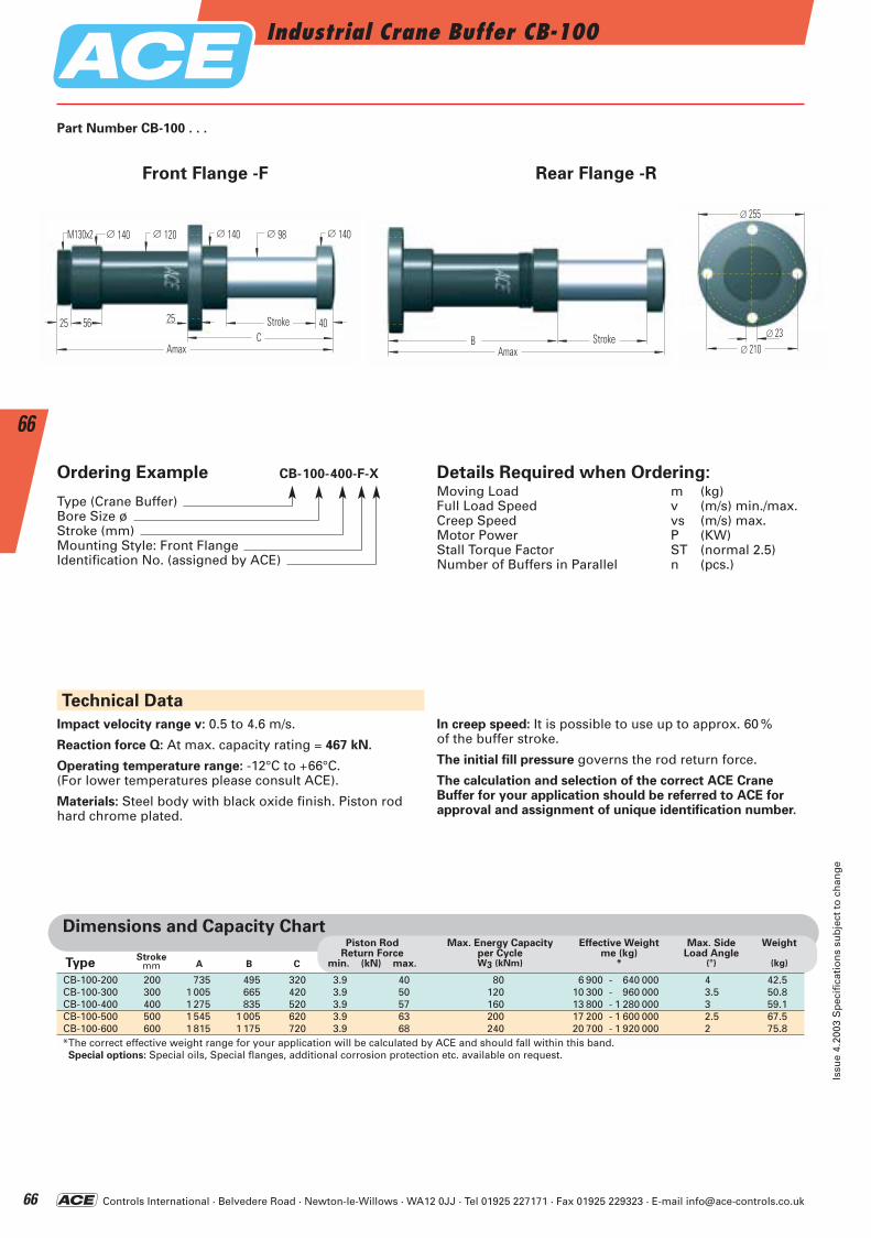
Controls International · Belvedere Road · Newton-le-Willows · WA12 0JJ · Tel 01925 227171 · Fax 01925 229323 · E-mail [email protected]
Industrial Crane Buffer CB-100
Issu
e 4.
2003
Sp
ecif
icat
ion
s su
bje
ct t
o c
han
ge
66
66
Front Flange -F Rear Flange -R
Technical Data
CB-100-200 200 735 495 320 3.9 40 80 6 900 - 640 000 4 42.5CB-100-300 300 1 005 665 420 3.9 50 120 10 300 - 960 000 3.5 50.8CB-100-400 400 1 275 835 520 3.9 57 160 13 800 - 1 280 000 3 59.1CB-100-500 500 1 545 1 005 620 3.9 63 200 17 200 - 1 600 000 2.5 67.5CB-100-600 600 1 815 1 175 720 3.9 68 240 20 700 - 1 920 000 2 75.8*The correct effective weight range for your application will be calculated by ACE and should fall within this band.Special options: Special oils, Special flanges, additional corrosion protection etc. available on request.
Dimensions and Capacity Chart
∅ 98
Amax
40
∅ 140M130x2 ∅ 120 ∅ 140 ∅ 140
HubC
255625
AmaxHubB
∅ 255
∅ 210∅ 23
Part Number CB-100 . . .
Ordering Example CB-100-400-F-X
Type (Crane Buffer)Bore Size øStroke (mm)Mounting Style: Front FlangeIdentification No. (assigned by ACE)
Details Required when Ordering:Moving Load m (kg)Full Load Speed v (m/s) min./max.Creep Speed vs (m/s) max.Motor Power P (KW)Stall Torque Factor ST (normal 2.5)Number of Buffers in Parallel n (pcs.)
A B C
Piston RodReturn Force
min. (kN) max.
Max. Energy Capacityper CycleW3 (kNm)
Effective Weight me (kg)
*
Max. SideLoad Angle
(°)
Weight
(kg)Stroke
mm Type
Impact velocity range v: 0.5 to 4.6 m/s.
Reaction force Q: At max. capacity rating = 467 kN.
Operating temperature range: -12°C to +66°C.(For lower temperatures please consult ACE).
Materials: Steel body with black oxide finish. Piston rodhard chrome plated.
In creep speed: It is possible to use up to approx. 60 % of the buffer stroke.
The initial fill pressure governs the rod return force.
The calculation and selection of the correct ACE CraneBuffer for your application should be referred to ACE forapproval and assignment of unique identification number.
StrokeStroke
ACE-Kat_2003_UK_062-067 22.09.2003 17:37 Uhr Seite 66
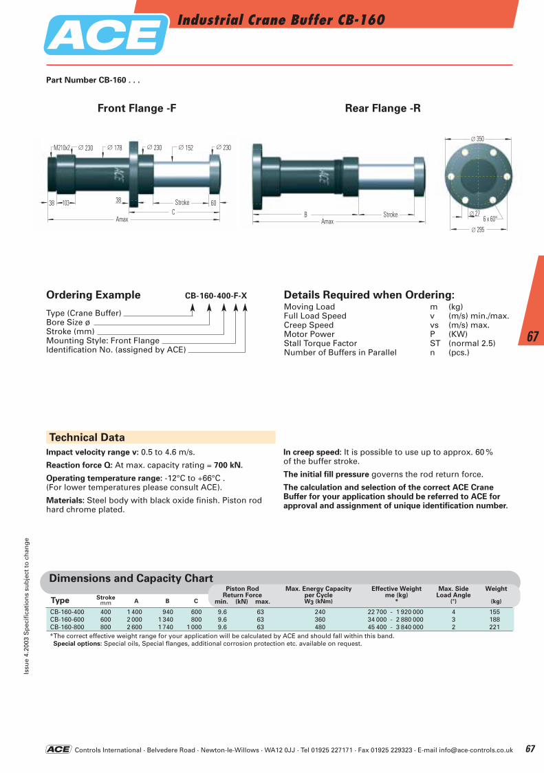
Controls International · Belvedere Road · Newton-le-Willows · WA12 0JJ · Tel 01925 227171 · Fax 01925 229323 · E-mail [email protected]
Industrial Crane Buffer CB-160Is
sue
4.20
03 S
pec
ific
atio
ns
sub
ject
to
ch
ang
e
67
67
Details Required when Ordering:Moving Load m (kg)Full Load Speed v (m/s) min./max.Creep Speed vs (m/s) max.Motor Power P (KW)Stall Torque Factor ST (normal 2.5)Number of Buffers in Parallel n (pcs.)
Technical Data
Dimensions and Capacity Chart
Front Flange -F Rear Flange -R
∅ 152
Amax
60
∅ 230M210x2 ∅ 178 ∅ 230 ∅ 230
HubC
3810338
AmaxHubB
∅ 350
∅ 295
∅ 276 x 60°
Part Number CB-160 . . .
Ordering Example CB-160-400-F-X
Type (Crane Buffer)Bore Size øStroke (mm)Mounting Style: Front FlangeIdentification No. (assigned by ACE)
A B C
Piston RodReturn Force
min. (kN) max.
Max. Energy Capacityper CycleW3 (kNm)
Effective Weight me (kg)
*
Max. SideLoad Angle
(°)
Weight
(kg)Stroke
mmType
CB-160-400 400 1 400 940 600 9.6 63 240 22 700 - 1 920 000 4 155CB-160-600 600 2 000 1 340 800 9.6 63 360 34 000 - 2 880 000 3 188CB-160-800 800 2 600 1 740 1 000 9.6 63 480 45 400 - 3 840 000 2 221*The correct effective weight range for your application will be calculated by ACE and should fall within this band.Special options: Special oils, Special flanges, additional corrosion protection etc. available on request.
Impact velocity range v: 0.5 to 4.6 m/s.
Reaction force Q: At max. capacity rating = 700 kN.
Operating temperature range: -12°C to +66°C .(For lower temperatures please consult ACE).
Materials: Steel body with black oxide finish. Piston rodhard chrome plated.
In creep speed: It is possible to use up to approx. 60 % of the buffer stroke.
The initial fill pressure governs the rod return force.
The calculation and selection of the correct ACE CraneBuffer for your application should be referred to ACE forapproval and assignment of unique identification number.
Stroke
Stroke
ACE-Kat_2003_UK_062-067 22.09.2003 17:37 Uhr Seite 67
Controls International · Belvedere Road · Newton-le-Willows · WA12 0JJ · Tel 01925 227171 · Fax 01925 229323 · E-mail [email protected]
Safety Shock AbsorbersManual
Issu
e 4.
2003
Sp
ecif
icat
ion
s su
bje
ct t
o c
han
ge
68
68
ACE security shock absorbers are high-quality products.To achieve long-lasting and trouble free operating lifeplease read the following instructions before installation.
Inner Pressure tube characteristics
The inner pressure tube is individually designed and manufactured for each specific application.When several safety shock absorbers of the same size butwith different metering orifice patterns are used in one system it is important that the mounting positions are notmixed up.Safety shock absorbers have individually designed orifice patterns depending upon application andtherefore must only be installed in correct position.
The calculation and selection of the correct safety shock
absorbers should be performed or checked by ACE.
Mounting
To mount the shock absorber, we recommend the use oforiginal ACE mounting accessories shown in catalogue.The mounting of each shock absorber must be exactly po-sitioned so that the reaction force (Q) can be adequatelytransmitted into the mounting structure.ACE recommends installation via the front flange – F
mounting style that ensures the maximum protectionagainst buckling.The damper must be mounted so that the moving loadsare decelerated with the least possible side loading to thepiston rod. The maximum permissable side load anglesare detailed in our current catalogue.The entire stroke length must be used for deceleration because only using part of the stroke can lead to over-stressing and damage to the unit.
Environmental requirements
The permissible temperature range for each shock absorber type can be found in our current catalogue. CAUTION: Useage outside the specified temperature range can lead to premature breakdown and damage of of the shock absorbers which can then result in severe system damage or machine failures.Trouble free operation outdoors or in damp environmentsis only warranted if the dampers are coated with a specificcorrosion protection finish.
Initial Start-Up Checks
First impacts on the shock absorber should only be triedafter correctly mounting and with reduced impact speedsand – if possible – with reduced load. Differences betweencalculated and actual operating data can then be detectedearly on, and damage to your system can be avoided. Ifthe shock absorbers were selected on calculated data thatdoes not correspond to the maximum possible loading(i.e. selection based on drive power being switched off orat reduced impact speed) then these restricted impact conditions must not be exceeded during initial testing orsubsequent use of the system. Otherwise you risk dama-ging the shock absorbers and/or your machine by over-stressing materials. After the initial trial check that thepiston rod fully extends again and that there are no signsof oil leakage . Also check that the mounting hardware isstill securely tightened up.You need to satisfy yourself that no damage has occurredto the piston rod or the body or the mounting hardware.
Fixed Mechanical Stop
Safety shock absorbers do not need an external mechanicalstop. The stroke of the safety shock absorber is limited by the contact of the rod end button onto the front body ofthe shock absorber (with type SCS 33 to SCS 64 by theload contacting the integral stop collar).
What needs to be checked after a full load impact?
Safety shock absorbers that were originally checked onlyat reduced speed or load need to be checked again after afull load impact (i.e. Emergency use) has occurred.Check that the piston rod fully extends to it's full out posi-tion, that there are no signs of oil leakage and that themounting hardware is still securely fixed.You need to satisfy yourself that no damage has occurredto the piston rod or the body or the mounting hardware. If no damage has occurred, the safety shock absorber canbe put back into normal operation (see initial start-up).
Maintenance
Safety shock absorbers are sealed systems and do notneed special maintenance. Safety shock absorbers that arenot used regularly (i.e. that are intended for Emergencystop systems) should be checked within the normal timeframe for safety checks, but at least once a year. At thistime special attention must be paid to checking that thepiston rod resets to its fully extended position , that thereis no oil leakage and that the mounting brackets are stillsecure and undamaged. The piston rod must not showany signs of damage. Safety shock absorbers that are inuse regularly should be checked every three months.
Repair Notice
If any damage to the shock absorber is detected or if thereare any doubts as to the proper functioning of the unit please send the unit for service to ACE. Alternatively con-tact your local ACE office for further advice.
Manual and maintenance instructions for safety shock absorbers type SCS and CB
Mounting style front flange – F
Safety Shock Absorber CBSafety Shock Absorber SCS
ACE-Kat_2003_UK_068-073 22.09.2003 17:40 Uhr Seite 68
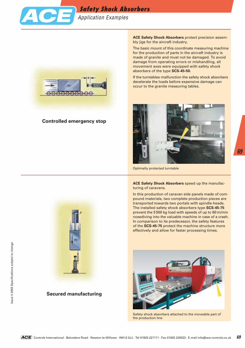
Controls International · Belvedere Road · Newton-le-Willows · WA12 0JJ · Tel 01925 227171 · Fax 01925 229323 · E-mail [email protected]
Secured manufacturing
Controlled emergency stop
ACE Safety Shock Absorbers protect precision assem-bly jigs for the aircraft industry.
The basic mount of this coordinate measuring machinefor the production of parts in the aircraft industry ismade of granite and must not be damaged. To avoiddamage from operating errors or mishandling, all movement axes were equipped with safety shock absorbers of the type SCS-45-50.
If the turntables malfunction the safety shock absorbersdecelerate the loads before expensive damage can occur to the granite measuring tables.
ACE Safety Shock Absorbers speed up the manufac-turing of caravans.
In this production of caravan side panels made of com-pound materials, two complete production pieces aretransported towards two portals with spindle-heads.The installed safety shock absorbers type SCS-45-75
prevent the 5 500 kg load with speeds of up to 60 m/minnosediving into the valuable machine in case of a crash.In comparison to its predecessor, the safety features of the SCS-45-75 protect the machine structure more effectively and allow for faster processing times.
Optimally protected turntable
Safety shock absorbers attached to the moveable part ofthe production line
Safety Shock AbsorbersApplication Examples
Issu
e 4.
2003
Sp
ecif
icat
ion
s su
bje
ct t
o c
han
ge
69
69
ACE-Kat_2003_UK_068-073 22.09.2003 17:41 Uhr Seite 69
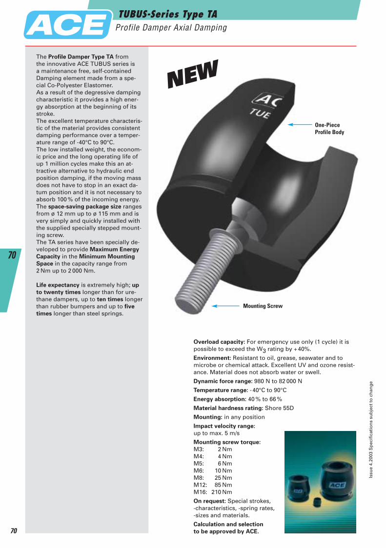
The Profile Damper Type TA from the innovative ACE TUBUS series is a maintenance free, self-containedDamping element made from a spe-cial Co-Polyester Elastomer. As a result of the degressive dampingcharacteristic it provides a high ener-gy absorption at the beginning of itsstroke.The excellent temperature characteris-tic of the material provides consistentdamping performance over a temper-ature range of -40°C to 90°C.The low installed weight, the econom-ic price and the long operating life ofup 1 million cycles make this an at-tractive alternative to hydraulic endposition damping, if the moving massdoes not have to stop in an exact da-tum position and it is not necessary toabsorb 100 % of the incoming energy.The space-saving package size rangesfrom ø 12 mm up to ø 115 mm and isvery simply and quickly installed withthe supplied specially stepped mount-ing screw.The TA series have been specially de-veloped to provide Maximum Energy
Capacity in the Minimum Mounting
Space in the capacity range from 2 Nm up to 2 000 Nm.
Life expectancy is extremely high; up
to twenty times longer than for ure-thane dampers, up to ten times longerthan rubber bumpers and up to five
times longer than steel springs.Mounting Screw
Overload capacity: For emergency use only (1 cycle) it ispossible to exceed the W3 rating by +40%.
Environment: Resistant to oil, grease, seawater and to microbe or chemical attack. Excellent UV and ozone resist-ance. Material does not absorb water or swell.
Dynamic force range: 980 N to 82 000 N
Temperature range: -40°C to 90°C
Energy absorption: 40 % to 66 %
Material hardness rating: Shore 55D
Mounting: in any position
Impact velocity range:
up to max. 5 m/s
Mounting screw torque:
M3: 2 NmM4: 4 NmM5: 6 NmM6: 10 NmM8: 25 NmM12: 85 NmM16: 210 Nm
On request: Special strokes, -characteristics, -spring rates, -sizes and materials.
Calculation and selection
to be approved by ACE.
One-Piece Profile Body
TUBUS-Series Type TAProfile Damper Axial Damping
Issu
e 4.
2003
Sp
ecif
icat
ion
s su
bje
ct t
o c
han
ge
70
70
NEW
ACE-Kat_2003_UK_068-073 22.09.2003 17:41 Uhr Seite 70
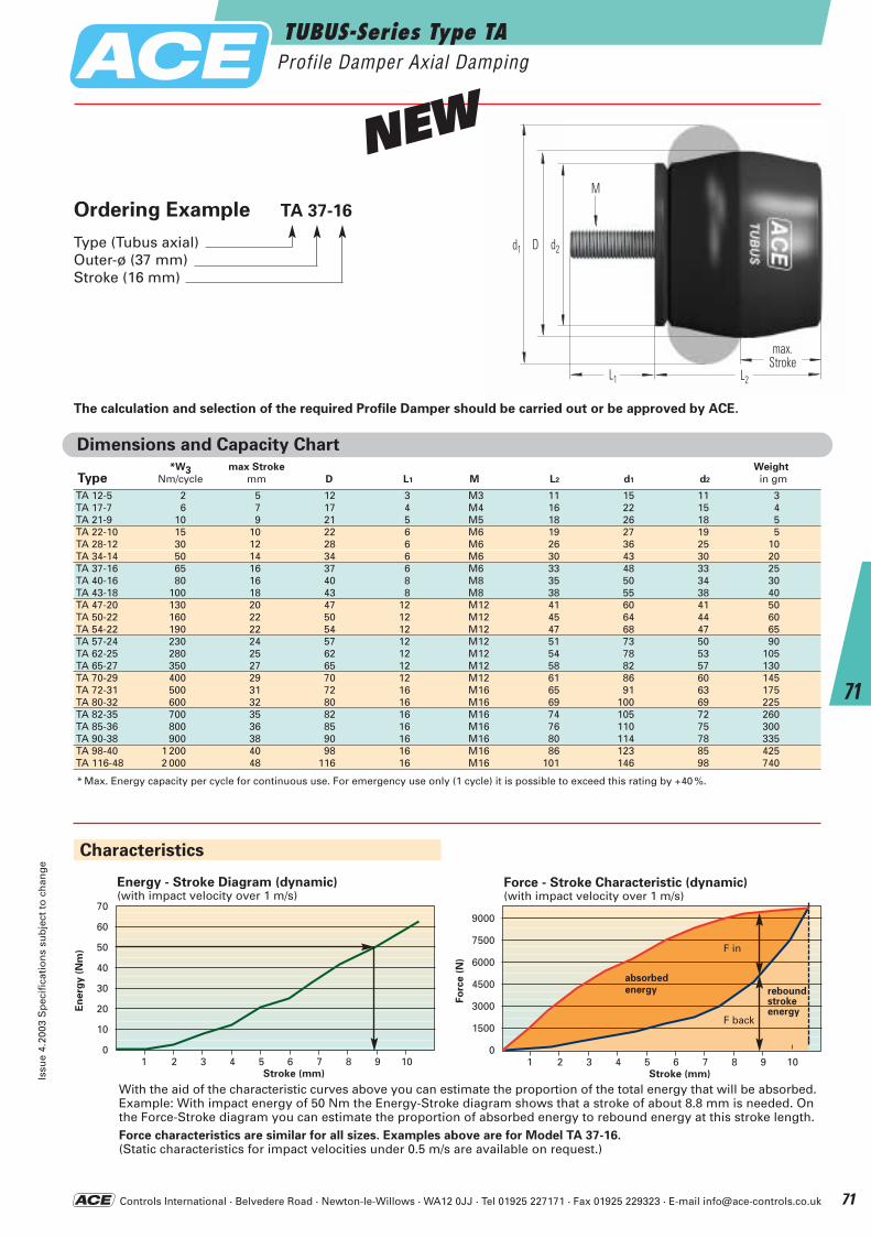
Controls International · Belvedere Road · Newton-le-Willows · WA12 0JJ · Tel 01925 227171 · Fax 01925 229323 · E-mail [email protected]
Dimensions and Capacity Chart*W3 max Stroke Weight
Type Nm/cycle mm D L1 M L2 d1 d2 in gm
TA 12-5 2 5 12 3 M3 11 15 11 3TA 17-7 6 7 17 4 M4 16 22 15 4TA 21-9 10 9 21 5 M5 18 26 18 5TA 22-10 15 10 22 6 M6 19 27 19 5TA 28-12 30 12 28 6 M6 26 36 25 10TA 34-14 50 14 34 6 M6 30 43 30 20TA 37-16 65 16 37 6 M6 33 48 33 25TA 40-16 80 16 40 8 M8 35 50 34 30TA 43-18 100 18 43 8 M8 38 55 38 40TA 47-20 130 20 47 12 M12 41 60 41 50TA 50-22 160 22 50 12 M12 45 64 44 60TA 54-22 190 22 54 12 M12 47 68 47 65TA 57-24 230 24 57 12 M12 51 73 50 90TA 62-25 280 25 62 12 M12 54 78 53 105TA 65-27 350 27 65 12 M12 58 82 57 130TA 70-29 400 29 70 12 M12 61 86 60 145TA 72-31 500 31 72 16 M16 65 91 63 175TA 80-32 600 32 80 16 M16 69 100 69 225TA 82-35 700 35 82 16 M16 74 105 72 260TA 85-36 800 36 85 16 M16 76 110 75 300TA 90-38 900 38 90 16 M16 80 114 78 335TA 98-40 1 200 40 98 16 M16 86 123 85 425TA 116-48 2 000 48 116 16 M16 101 146 98 740
* Max. Energy capacity per cycle for continuous use. For emergency use only (1 cycle) it is possible to exceed this rating by +40 %.
70
60
50
40
30
20
10
0
Energy - Stroke Diagram (dynamic)(with impact velocity over 1 m/s)
En
erg
y (
Nm
)
1 2 3 4 5 6 7 8 9 10Stroke (mm)
With the aid of the characteristic curves above you can estimate the proportion of the total energy that will be absorbed.Example: With impact energy of 50 Nm the Energy-Stroke diagram shows that a stroke of about 8.8 mm is needed. On the Force-Stroke diagram you can estimate the proportion of absorbed energy to rebound energy at this stroke length.Force characteristics are similar for all sizes. Examples above are for Model TA 37-16.(Static characteristics for impact velocities under 0.5 m/s are available on request.)
reboundstrokeenergy
F back
d1 d2D
L1 L2
max.Hub
M
Ordering Example TA 37-16
Type (Tubus axial)Outer-ø (37 mm)Stroke (16 mm)
The calculation and selection of the required Profile Damper should be carried out or be approved by ACE.
Characteristics
9000
7500
6000
4500
3000
1500
0
Force - Stroke Characteristic (dynamic)(with impact velocity over 1 m/s)
Fo
rce (
N)
F in
absorbedenergy
1 2 3 4 5 6 7 8 9 10Stroke (mm)
TUBUS-Series Type TAProfile Damper Axial Damping
Issu
e 4.
2003
Sp
ecif
icat
ion
s su
bje
ct t
o c
han
ge
71
71
max.Stroke
NEW
ACE-Kat_2003_UK_068-073 22.09.2003 17:41 Uhr Seite 71
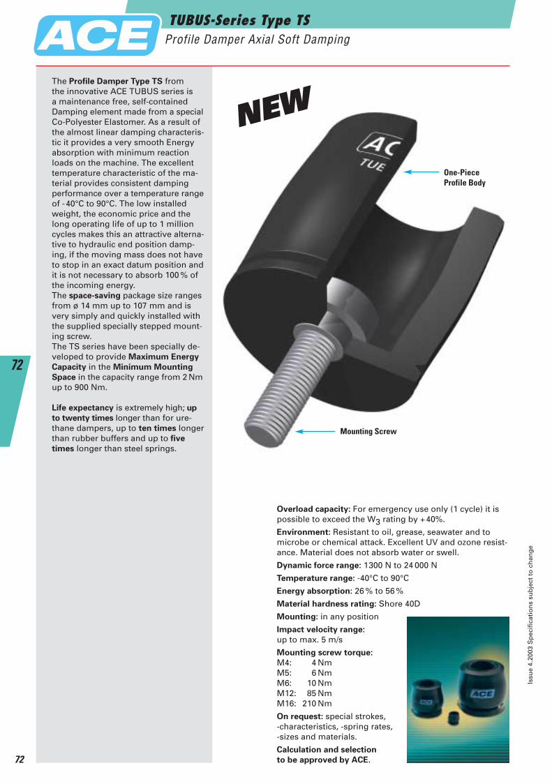
The Profile Damper Type TS from the innovative ACE TUBUS series is a maintenance free, self-containedDamping element made from a specialCo-Polyester Elastomer. As a result ofthe almost linear damping characteris-tic it provides a very smooth Energyabsorption with minimum reactionloads on the machine. The excellenttemperature characteristic of the ma-terial provides consistent dampingperformance over a temperature rangeof -40°C to 90°C. The low installedweight, the economic price and thelong operating life of up to 1 millioncycles makes this an attractive alterna-tive to hydraulic end position damp-ing, if the moving mass does not haveto stop in an exact datum position andit is not necessary to absorb 100 % ofthe incoming energy. The space-saving package size rangesfrom ø 14 mm up to 107 mm and isvery simply and quickly installed withthe supplied specially stepped mount-ing screw. The TS series have been specially de-veloped to provide Maximum Energy
Capacity in the Minimum Mounting
Space in the capacity range from 2 Nmup to 900 Nm.
Life expectancy is extremely high; up
to twenty times longer than for ure-thane dampers, up to ten times longerthan rubber buffers and up to five
times longer than steel springs.
Overload capacity: For emergency use only (1 cycle) it ispossible to exceed the W3 rating by +40%.
Environment: Resistant to oil, grease, seawater and to microbe or chemical attack. Excellent UV and ozone resist-ance. Material does not absorb water or swell.
Dynamic force range: 1300 N to 24 000 N
Temperature range: -40°C to 90°C
Energy absorption: 26 % to 56 %
Material hardness rating: Shore 40D
Mounting: in any position
Impact velocity range:
up to max. 5 m/s
Mounting screw torque:
M4: 4 NmM5: 6 NmM6: 10 NmM12: 85 NmM16: 210 Nm
On request: special strokes, -characteristics, -spring rates, -sizes and materials.
Calculation and selection
to be approved by ACE.
Mounting Screw
One-PieceProfile Body
TUBUS-Series Type TSProfile Damper Axial Soft Damping
Issu
e 4.
2003
Sp
ecif
icat
ion
s su
bje
ct t
o c
han
ge
72
72
NEW
ACE-Kat_2003_UK_068-073 22.09.2003 17:41 Uhr Seite 72
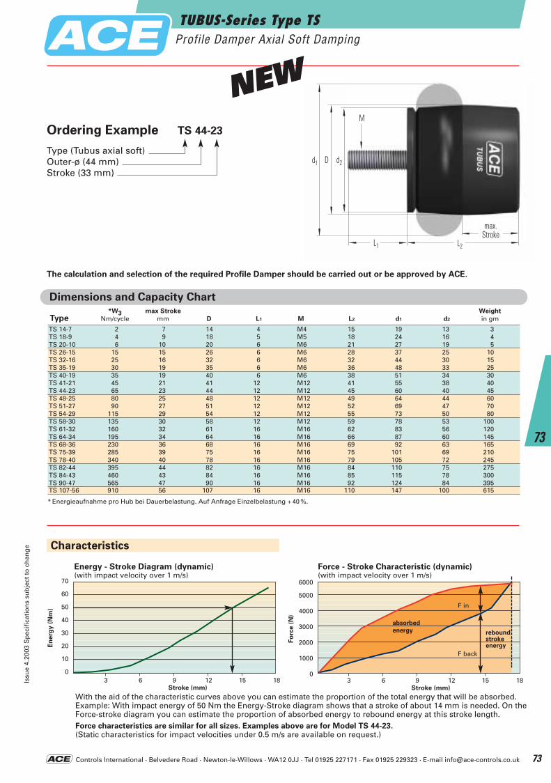
Controls International · Belvedere Road · Newton-le-Willows · WA12 0JJ · Tel 01925 227171 · Fax 01925 229323 · E-mail [email protected]
TUBUS-Series Type TSProfile Damper Axial Soft Damping
Issu
e 4.
2003
Sp
ecif
icat
ion
s su
bje
ct t
o c
han
ge
73
73
Dimensions and Capacity Chart*W3 max Stroke Weight
Type Nm/cycle mm D L1 M L2 d1 d2 in gm
TS 14-7 2 7 14 4 M4 15 19 13 3TS 18-9 4 9 18 5 M5 18 24 16 4TS 20-10 6 10 20 6 M6 21 27 19 5TS 26-15 15 15 26 6 M6 28 37 25 10TS 32-16 25 16 32 6 M6 32 44 30 15TS 35-19 30 19 35 6 M6 36 48 33 25TS 40-19 35 19 40 6 M6 38 51 34 30TS 41-21 45 21 41 12 M12 41 55 38 40TS 44-23 65 23 44 12 M12 45 60 40 45TS 48-25 80 25 48 12 M12 49 64 44 60TS 51-27 90 27 51 12 M12 52 69 47 70TS 54-29 115 29 54 12 M12 55 73 50 80TS 58-30 135 30 58 12 M12 59 78 53 100TS 61-32 160 32 61 16 M16 62 83 56 120TS 64-34 195 34 64 16 M16 66 87 60 145TS 68-36 230 36 68 16 M16 69 92 63 165TS 75-39 285 39 75 16 M16 75 101 69 210TS 78-40 340 40 78 16 M16 79 105 72 245TS 82-44 395 44 82 16 M16 84 110 75 275TS 84-43 460 43 84 16 M16 85 115 78 300TS 90-47 565 47 90 16 M16 92 124 84 395TS 107-56 910 56 107 16 M16 110 147 100 615
* Energieaufnahme pro Hub bei Dauerbelastung. Auf Anfrage Einzelbelastung + 40 %.
d1 d2D
L1 L2
max.Hub
M
The calculation and selection of the required Profile Damper should be carried out or be approved by ACE.
70
60
50
40
30
20
10
0
Energy - Stroke Diagram (dynamic)(with impact velocity over 1 m/s)
En
erg
y (
Nm
)
3 6 9 12 15 18Stroke (mm)
With the aid of the characteristic curves above you can estimate the proportion of the total energy that will be absorbed.Example: With impact energy of 50 Nm the Energy-Stroke diagram shows that a stroke of about 14 mm is needed. On theForce-stroke diagram you can estimate the proportion of absorbed energy to rebound energy at this stroke length.Force characteristics are similar for all sizes. Examples above are for Model TS 44-23.(Static characteristics for impact velocities under 0.5 m/s are available on request.)
reboundstrokeenergy
F back
Characteristics
6000
5000
4000
3000
2000
1000
0
Force - Stroke Characteristic (dynamic)(with impact velocity over 1 m/s)
Fo
rce (
N)
F in
absorbedenergy
Ordering Example TS 44-23
Type (Tubus axial soft)Outer-ø (44 mm)Stroke (33 mm)
3 6 9 12 15 18Stroke (mm)
max.Stroke
NEW
ACE-Kat_2003_UK_068-073 22.09.2003 17:42 Uhr Seite 73
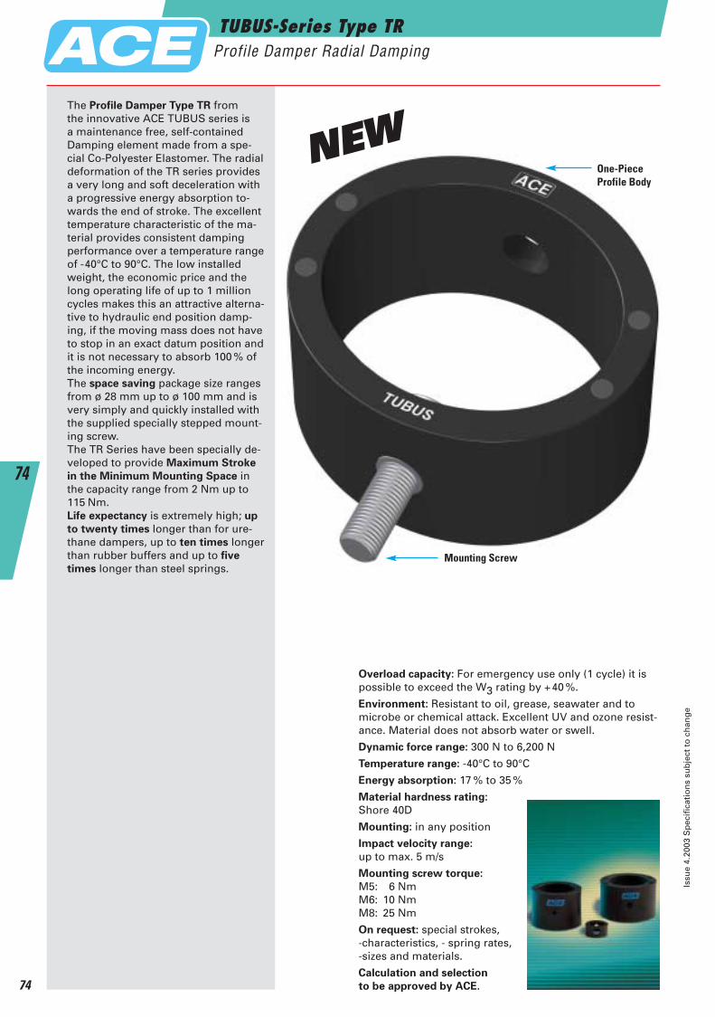
The Profile Damper Type TR from the innovative ACE TUBUS series is a maintenance free, self-containedDamping element made from a spe-cial Co-Polyester Elastomer. The radialdeformation of the TR series providesa very long and soft deceleration witha progressive energy absorption to-wards the end of stroke. The excellenttemperature characteristic of the ma-terial provides consistent dampingperformance over a temperature rangeof -40°C to 90°C. The low installedweight, the economic price and thelong operating life of up to 1 millioncycles makes this an attractive alterna-tive to hydraulic end position damp-ing, if the moving mass does not haveto stop in an exact datum position andit is not necessary to absorb 100 % ofthe incoming energy. The space saving package size rangesfrom ø 28 mm up to ø 100 mm and isvery simply and quickly installed withthe supplied specially stepped mount-ing screw. The TR Series have been specially de-veloped to provide Maximum Stroke
in the Minimum Mounting Space inthe capacity range from 2 Nm up to115 Nm.Life expectancy is extremely high; up
to twenty times longer than for ure-thane dampers, up to ten times longerthan rubber buffers and up to five
times longer than steel springs.
Overload capacity: For emergency use only (1 cycle) it ispossible to exceed the W3 rating by +40 %.
Environment: Resistant to oil, grease, seawater and to microbe or chemical attack. Excellent UV and ozone resist-ance. Material does not absorb water or swell.
Dynamic force range: 300 N to 6,200 N
Temperature range: -40°C to 90°C
Energy absorption: 17 % to 35 %
Material hardness rating:
Shore 40D
Mounting: in any position
Impact velocity range:
up to max. 5 m/s
Mounting screw torque:
M5: 6 NmM6: 10 NmM8: 25 Nm
On request: special strokes, -characteristics, - spring rates, -sizes and materials.
Calculation and selection
to be approved by ACE.
Mounting Screw
One-PieceProfile Body
TUBUS-Series Type TRProfile Damper Radial Damping
Issu
e 4.
2003
Sp
ecif
icat
ion
s su
bje
ct t
o c
han
ge
74
74
NEW
ACE-Kat_2003_UK_074-079 23.09.2003 11:08 Uhr Seite 74
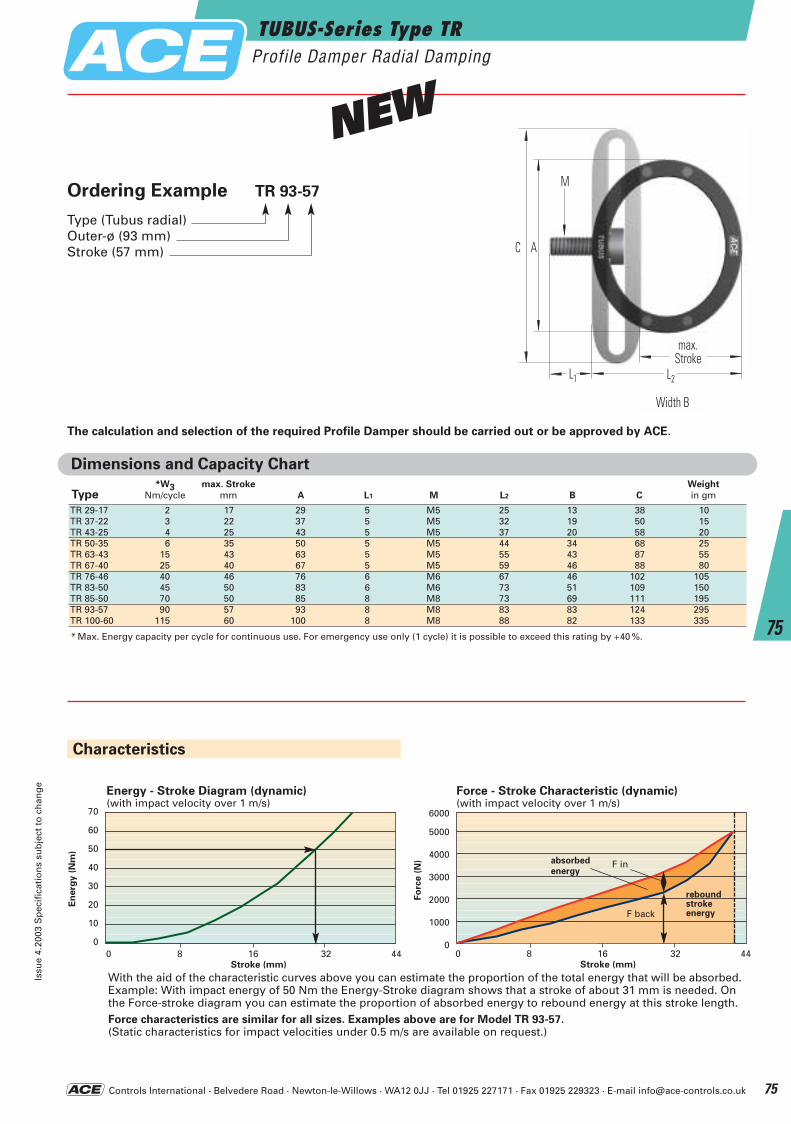
Controls International · Belvedere Road · Newton-le-Willows · WA12 0JJ · Tel 01925 227171 · Fax 01925 229323 · E-mail [email protected]
Dimensions and Capacity Chart*W3 max. Stroke Weight
Type Nm/cycle mm A L1 M L2 B C in gm
TR 29-17 2 17 29 5 M5 25 13 38 10TR 37-22 3 22 37 5 M5 32 19 50 15TR 43-25 4 25 43 5 M5 37 20 58 20TR 50-35 6 35 50 5 M5 44 34 68 25TR 63-43 15 43 63 5 M5 55 43 87 55TR 67-40 25 40 67 5 M5 59 46 88 80TR 76-46 40 46 76 6 M6 67 46 102 105TR 83-50 45 50 83 6 M6 73 51 109 150TR 85-50 70 50 85 8 M8 73 69 111 195TR 93-57 90 57 93 8 M8 83 83 124 295TR 100-60 115 60 100 8 M8 88 82 133 335
* Max. Energy capacity per cycle for continuous use. For emergency use only (1 cycle) it is possible to exceed this rating by +40 %.
C A
L1 L2
max.Hub
M
Tiefe B
The calculation and selection of the required Profile Damper should be carried out or be approved by ACE.
70
60
50
40
30
20
10
0
Energy - Stroke Diagram (dynamic)(with impact velocity over 1 m/s)
En
erg
y (
Nm
)
0 8 16 32 44Stroke (mm)
With the aid of the characteristic curves above you can estimate the proportion of the total energy that will be absorbed.Example: With impact energy of 50 Nm the Energy-Stroke diagram shows that a stroke of about 31 mm is needed. Onthe Force-stroke diagram you can estimate the proportion of absorbed energy to rebound energy at this stroke length.Force characteristics are similar for all sizes. Examples above are for Model TR 93-57.(Static characteristics for impact velocities under 0.5 m/s are available on request.)
reboundstrokeenergyF back
Characteristics
6000
5000
4000
3000
2000
1000
0
Force - Stroke Characteristic (dynamic)(with impact velocity over 1 m/s)
Fo
rce (
N) F inabsorbed
energy
0 8 16 32 44Stroke (mm)
Ordering Example TR 93-57
Type (Tubus radial)Outer-ø (93 mm)Stroke (57 mm)
TUBUS-Series Type TRProfile Damper Radial Damping
Issu
e 4.
2003
Sp
ecif
icat
ion
s su
bje
ct t
o c
han
ge
75
75
max.Stroke
Width B
NEW
ACE-Kat_2003_UK_074-079 23.09.2003 11:08 Uhr Seite 75
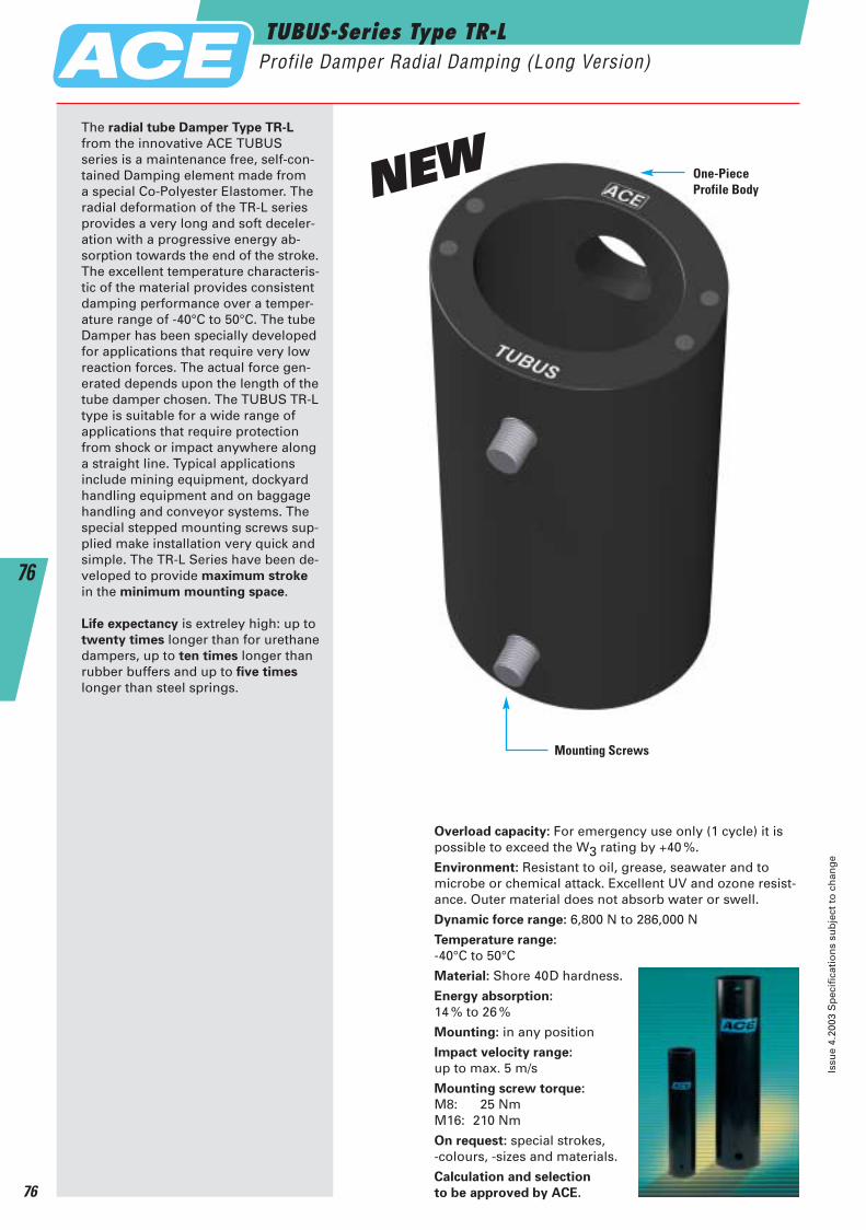
The radial tube Damper Type TR-L
from the innovative ACE TUBUS series is a maintenance free, self-con-tained Damping element made from a special Co-Polyester Elastomer. Theradial deformation of the TR-L seriesprovides a very long and soft deceler-ation with a progressive energy ab-sorption towards the end of the stroke.The excellent temperature characteris-tic of the material provides consistentdamping performance over a temper-ature range of -40°C to 50°C. The tubeDamper has been specially developedfor applications that require very lowreaction forces. The actual force gen-erated depends upon the length of thetube damper chosen. The TUBUS TR-Ltype is suitable for a wide range of applications that require protectionfrom shock or impact anywhere alonga straight line. Typical applications include mining equipment, dockyardhandling equipment and on baggagehandling and conveyor systems. Thespecial stepped mounting screws sup-plied make installation very quick andsimple. The TR-L Series have been de-veloped to provide maximum stroke
in the minimum mounting space.
Life expectancy is extreley high: up totwenty times longer than for urethanedampers, up to ten times longer thanrubber buffers and up to five times
longer than steel springs.
Overload capacity: For emergency use only (1 cycle) it ispossible to exceed the W3 rating by +40 %.
Environment: Resistant to oil, grease, seawater and to microbe or chemical attack. Excellent UV and ozone resist-ance. Outer material does not absorb water or swell.
Dynamic force range: 6,800 N to 286,000 N
Temperature range:
-40°C to 50°C
Material: Shore 40D hardness.
Energy absorption:
14 % to 26 %
Mounting: in any position
Impact velocity range:
up to max. 5 m/s
Mounting screw torque:
M8: 25 NmM16: 210 Nm
On request: special strokes, -colours, -sizes and materials.
Calculation and selection
to be approved by ACE.
Mounting Screws
One-PieceProfile Body
TUBUS-Series Type TR-LProfile Damper Radial Damping (Long Version)
Issu
e 4.
2003
Sp
ecif
icat
ion
s su
bje
ct t
o c
han
ge
76
76
NEW
ACE-Kat_2003_UK_074-079 23.09.2003 11:08 Uhr Seite 76
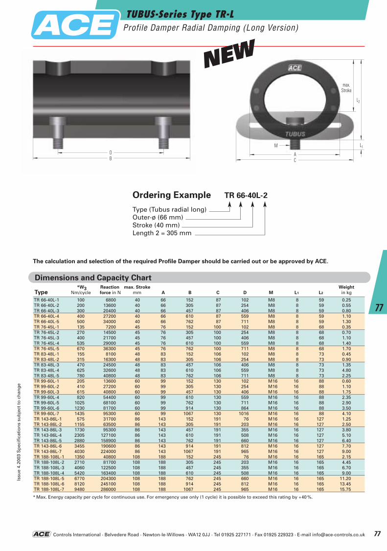
Controls International · Belvedere Road · Newton-le-Willows · WA12 0JJ · Tel 01925 227171 · Fax 01925 229323 · E-mail [email protected]
*W3 Reaction max. Stroke Weight
Type Nm/cycle force in N mm A B C D M L1 L2 in kg
TR 66-40L-1 100 6800 40 66 152 87 102 M8 8 59 0.25TR 66-40L-2 200 13600 40 66 305 87 254 M8 8 59 0.55TR 66-40L-3 300 20400 40 66 457 87 406 M8 8 59 0.80TR 66-40L-4 400 27200 40 66 610 87 559 M8 8 59 1.10TR 66-40L-5 500 34000 40 66 762 87 711 M8 8 59 1.30TR 76-45L-1 135 7200 45 76 152 100 102 M8 8 68 0.35TR 76-45L-2 270 14500 45 76 305 100 254 M8 8 68 0.70TR 76-45L-3 400 21700 45 76 457 100 406 M8 8 68 1.10TR 76-45L-4 535 29000 45 76 610 100 559 M8 8 68 1.40TR 76-45L-5 670 36300 45 76 762 100 711 M8 8 68 1.70TR 83-48L-1 155 8100 48 83 152 106 102 M8 8 73 0.45TR 83-48L-2 315 16300 48 83 305 106 254 M8 8 73 0.90TR 83-48L-3 470 24500 48 83 457 106 406 M8 8 73 1.35TR 83-48L-4 625 32600 48 83 610 106 559 M8 8 73 4.80TR 83-48L-5 780 40800 48 83 762 106 711 M8 8 73 2.25TR 99-60L-1 205 13600 60 99 152 130 102 M16 16 88 0.60TR 99-60L-2 410 27200 60 99 305 130 254 M16 16 88 1.10TR 99-60L-3 615 40800 60 99 457 130 406 M16 16 88 1.75TR 99-60L-4 820 54400 60 99 610 130 559 M16 16 88 2.35TR 99-60L-5 1025 68100 60 99 762 130 711 M16 16 88 2.90TR 99-60L-6 1230 81700 60 99 914 130 864 M16 16 88 3.50TR 99-60L-7 1435 95300 60 99 1067 130 1016 M16 16 88 4.10TR 143-86L-1 575 31700 86 143 152 191 76 M16 16 127 1.25TR 143-86L-2 1155 63500 86 143 305 191 203 M16 16 127 2.50TR 143-86L-3 1730 95300 86 143 457 191 355 M16 16 127 3.80TR 143-86L-4 2305 127100 86 143 610 191 508 M16 16 127 5.10TR 143-86L-5 2880 158900 86 143 762 191 660 M16 16 127 6.40TR 143-86L-6 3455 190600 86 143 914 191 812 M16 16 127 7.70TR 143-86L-7 4030 224000 86 143 1067 191 965 M16 16 127 9.00TR 188-108L-1 1350 40800 108 188 152 245 76 M16 16 165 2.15TR 188-108L-2 2710 81700 108 188 305 245 203 M16 16 165 4.45TR 188-108L-3 4060 122500 108 188 457 245 355 M16 16 165 6.70TR 188-108L-4 5420 163400 108 188 610 245 508 M16 16 165 9.00TR 188-108L-5 6770 204300 108 188 762 245 660 M16 16 165 11.20TR 188-108L-6 8120 245100 108 188 914 245 812 M16 16 165 13.45TR 188-108L-7 9480 286000 108 188 1067 245 965 M16 16 165 15.75
* Max. Energy capacity per cycle for continuous use. For emergency use only (1 cycle) it is possible to exceed this rating by +40 %.
Dimensions and Capacity Chart
The calculation and selection of the required Profile Damper should be carried out or be approved by ACE.
L1
L2
max.Hub
A
M
CDB
Ordering Example TR 66-40L-2
Type (Tubus radial long)Outer-ø (66 mm)Stroke (40 mm)Length 2 = 305 mm
TUBUS-Series Type TR-LProfile Damper Radial Damping (Long Version)
Issu
e 4.
2003
Sp
ecif
icat
ion
s su
bje
ct t
o c
han
ge
77
77
max.Stroke
NEW
ACE-Kat_2003_UK_074-079 23.09.2003 11:09 Uhr Seite 77
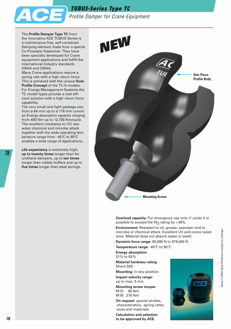
The Profile Damper Type TC from the innovative ACE TUBUS Series is a maintenance free, self-containedDamping element made from a specialCo-Polyester Elastomer. They havebeen specially developed for Craneequipment applications and fulfill theinternational Industry standardsOSHA and CMAA. Many Crane applications require aspring rate with a high return force.This is achieved with the unique Dual-
Profile Concept of the TC-S models.For Energy-Management-Systems theTC model types provide a cost effi-cient solution with a high return forcecapability. The very small and light package sizefrom ø 64 mm up to ø 176 mm coversan Energy absorption capacity rangingfrom 450 Nm up to 12,700 Nm/cycle.The excellent resistance to UV, sea-water chemical and microbe attack together with the wide operating tem-perature range from -40°C to 90°C enables a wide range of applications.
Life expectancy is extremely high; up to twenty times longer than forurethane dampers, up to ten times
longer than rubber buffers and up tofive times longer than steel springs.
Overload capacity: For emergency use only (1 cycle) it ispossible to exceed the W3 rating by +40%.
Environment: Resistant to oil, grease, seawater and to microbe or chemical attack. Excellent UV and ozone resist-ance. Material does not absorb water or swell.
Dynamic force range: 80,000 N to 978,000 N
Temperature range: -40°C to 90°C
Energy absorption:
31% to 63 %
Material hardness rating:
Shore 55D
Mounting: in any position
Impact velocity range:
up to max. 5 m/s
Mounting screw torque:
M12: 85 NmM16: 210 Nm
On request: special strokes, -characteristics, -spring rates, -sizes and materials.
Calculation and selection
to be approved by ACE.
Mounting Screw
One-PieceProfile Body
TUBUS-Series Type TCProfile Damper for Crane Equipment
Issu
e 4.
2003
Sp
ecif
icat
ion
s su
bje
ct t
o c
han
ge
78
78
NEW
ACE-Kat_2003_UK_074-079 23.09.2003 11:09 Uhr Seite 78
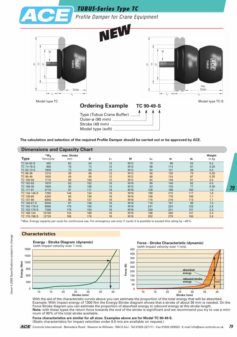
Controls International · Belvedere Road · Newton-le-Willows · WA12 0JJ · Tel 01925 227171 · Fax 01925 229323 · E-mail [email protected]
Dimensions and Capacity Chart*W3 max. Stroke Weight
Type Nm/cycle mm D L1 M L2 d1 d2 in kg
TC 64-62-S 450 62 64 12 M12 79 89 52 0.2TC 74-76-S 980 76 74 12 M12 96 114 61 0.25TC 83-73-S 1900 73 83 12 M12 94 127 69 0.3TC 86-39 1210 39 86 12 M12 56 133 78 0.25TC 90-49 1630 49 90 12 M12 68 124 67 0.25TC 100-59 1770 59 100 12 M12 84 149 91 0.5TC 102-63 1970 63 102 16 M16 98 140 82 0.5TC 108-30 1900 30 108 12 M12 53 133 77 0.35TC 117-97 3710 97 117 16 M16 129 188 100 1.0TC 134-146-S 7290 146 134 16 M16 188 215 117 1.6TC 136-65 4250 65 136 16 M16 106 178 106 1.1TC 137-90 6350 90 137 16 M16 115 216 113 1.1TC 146-67-S 8330 67 146 16 M16 118 191 99 1.5TC 150-178-S 8860 178 150 16 M16 241 224 132 2.6TC 153-178-S 7260 178 153 16 M16 226 241 131 2.3TC 168-124 10100 124 168 16 M16 166 260 147 2.3TC 176-198-S 12720 198 176 16 M16 252 279 150 3.6
* Max. Energy capacity per cycle for continuous use. For emergency use only (1 cycle) it is possible to exceed this rating by +40 %.
d1 d2D
L1 L2
max.Hub
M
The calculation and selection of the required Profile Damper should be carried out or be approved by ACE.
Ordering Example TC 90-49-S
Type (Tubus Crane Buffer)Outer-ø (90 mm)Stroke (49 mm)Model type (soft)
1800
1500
1200
900
600
300
0
Energy - Stroke Diagram (dynamic)(with impact velocity over 1 m/s)
En
erg
y (
Nm
)
10 15 20 25 30 35 40Stroke (mm)
With the aid of the characteristic curves above you can estimate the proportion of the total energy that will be absorbed.Example: With impact energy of 1300 Nm the Energy-Stroke diagram shows that a stroke of about 38 mm is needed. On theForce-Stroke diagram you can estimate the proportion of absorbed energy to rebound energy at this stroke length.Note: with these types the return force towards the end of the stroke is significant and we recommend you try to use a mini-mum of 90% of the total stroke available.Force characteristics are similar for all sizes. Examples above are for Model TC 90-49-S.(Static characteristics for impact velocities under 0.5 m/s are available on request.)
rebound strokeenergy
F back
Characteristics
450
400
350
300
250
200
150
100
50
0
Force - Stroke Characteristic (dynamic)(with impact velocity over 1 m/s)
Fo
rce (
N)
F in
absorbedenergy
10 15 20 25 30 35 40Stroke (mm)
Model type TC-SModel type TC
TUBUS-Series Type TCProfile Damper for Crane Equipment
Issu
e 4.
2003
Sp
ecif
icat
ion
s su
bje
ct t
o c
han
ge
79
79
Hubmax.
Stroke
d1 d2D
L1 L2
Hub
M
Stroke
NEW
ACE-Kat_2003_UK_074-079 23.09.2003 11:09 Uhr Seite 79
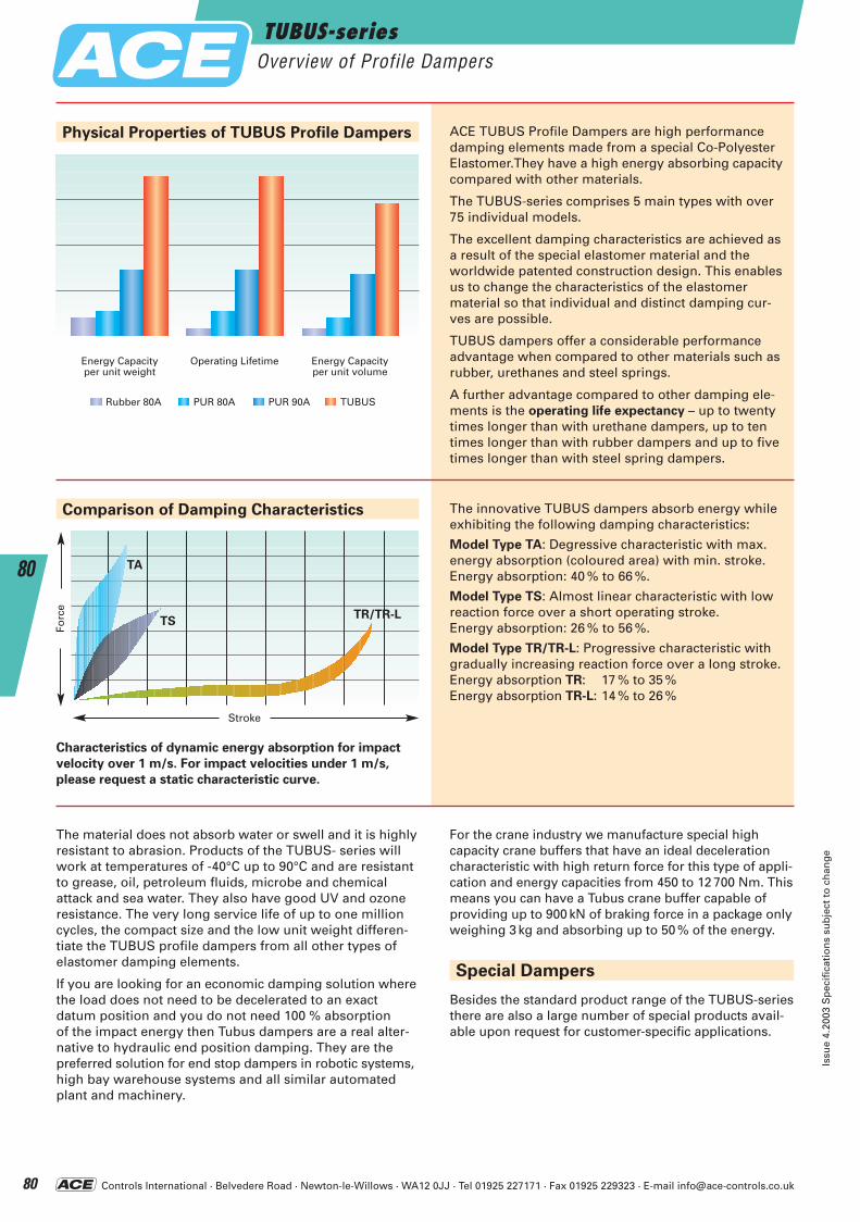
Controls International · Belvedere Road · Newton-le-Willows · WA12 0JJ · Tel 01925 227171 · Fax 01925 229323 · E-mail [email protected]
Besides the standard product range of the TUBUS-seriesthere are also a large number of special products avail-able upon request for customer-specific applications.
Energy Capacity Operating Lifetime Energy Capacityper unit weight per unit volume
Rubber 80A PUR 80A PUR 90A TUBUS
Physical Properties of TUBUS Profile Dampers ACE TUBUS Profile Dampers are high performancedamping elements made from a special Co-PolyesterElastomer.They have a high energy absorbing capacitycompared with other materials.
The TUBUS-series comprises 5 main types with over75 individual models.
The excellent damping characteristics are achieved asa result of the special elastomer material and theworldwide patented construction design. This enablesus to change the characteristics of the elastomer material so that individual and distinct damping cur-ves are possible.
TUBUS dampers offer a considerable performance advantage when compared to other materials such asrubber, urethanes and steel springs.
A further advantage compared to other damping ele-ments is the operating life expectancy – up to twentytimes longer than with urethane dampers, up to ten times longer than with rubber dampers and up to fivetimes longer than with steel spring dampers.
The innovative TUBUS dampers absorb energy whileexhibiting the following damping characteristics:
Model Type TA: Degressive characteristic with max.energy absorption (coloured area) with min. stroke.Energy absorption: 40 % to 66 %.
Model Type TS: Almost linear characteristic with lowreaction force over a short operating stroke. Energy absorption: 26 % to 56 %.
Model Type TR/TR-L: Progressive characteristic withgradually increasing reaction force over a long stroke.Energy absorption TR: 17 % to 35 %Energy absorption TR-L: 14 % to 26 %
For the crane industry we manufacture special high capacity crane buffers that have an ideal decelerationcharacteristic with high return force for this type of appli-cation and energy capacities from 450 to 12 700 Nm. Thismeans you can have a Tubus crane buffer capable ofproviding up to 900 kN of braking force in a package onlyweighing 3 kg and absorbing up to 50 % of the energy.
The material does not absorb water or swell and it is highlyresistant to abrasion. Products of the TUBUS- series willwork at temperatures of -40°C up to 90°C and are resistantto grease, oil, petroleum fluids, microbe and chemical attack and sea water. They also have good UV and ozoneresistance. The very long service life of up to one millioncycles, the compact size and the low unit weight differen-tiate the TUBUS profile dampers from all other types ofelastomer damping elements.
If you are looking for an economic damping solution wherethe load does not need to be decelerated to an exact datum position and you do not need 100 % absorption of the impact energy then Tubus dampers are a real alter-native to hydraulic end position damping. They are thepreferred solution for end stop dampers in robotic systems,high bay warehouse systems and all similar automatedplant and machinery.
TUBUS-seriesOverview of Profile Dampers
Issu
e 4.
2003
Sp
ecif
icat
ion
s su
bje
ct t
o c
han
ge
80
80
Characteristics of dynamic energy absorption for impact
velocity over 1 m/s. For impact velocities under 1 m/s,
please request a static characteristic curve.
TA
TSTR/TR-L
Forc
e
Stroke
Comparison of Damping Characteristics
Special Dampers
ACE-Kat_2003_UK_080-085 22.09.2003 17:51 Uhr Seite 80
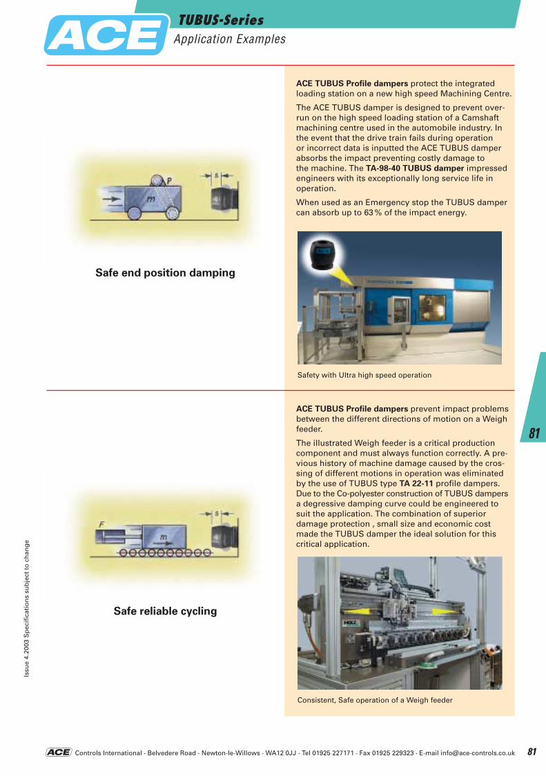
Controls International · Belvedere Road · Newton-le-Willows · WA12 0JJ · Tel 01925 227171 · Fax 01925 229323 · E-mail [email protected]
TUBUS-SeriesApplication Examples
Issu
e 4.
2003
Sp
ecif
icat
ion
s su
bje
ct t
o c
han
ge
81
81
Safety with Ultra high speed operation
Consistent, Safe operation of a Weigh feeder
ACE TUBUS Profile dampers protect the integrated loading station on a new high speed Machining Centre.
The ACE TUBUS damper is designed to prevent over-run on the high speed loading station of a Camshaftmachining centre used in the automobile industry. Inthe event that the drive train fails during operation or incorrect data is inputted the ACE TUBUS damperabsorbs the impact preventing costly damage to the machine. The TA-98-40 TUBUS damper impressedengineers with its exceptionally long service life in operation.
When used as an Emergency stop the TUBUS dampercan absorb up to 63 % of the impact energy.
ACE TUBUS Profile dampers prevent impact problemsbetween the different directions of motion on a Weighfeeder.
The illustrated Weigh feeder is a critical productioncomponent and must always function correctly. A pre-vious history of machine damage caused by the cros-sing of different motions in operation was eliminatedby the use of TUBUS type TA 22-11 profile dampers.Due to the Co-polyester construction of TUBUS dampersa degressive damping curve could be engineered tosuit the application. The combination of superior damage protection , small size and economic costmade the TUBUS damper the ideal solution for this critical application.
Safe end position damping
Safe reliable cycling
ACE-Kat_2003_UK_080-085 22.09.2003 17:51 Uhr Seite 81
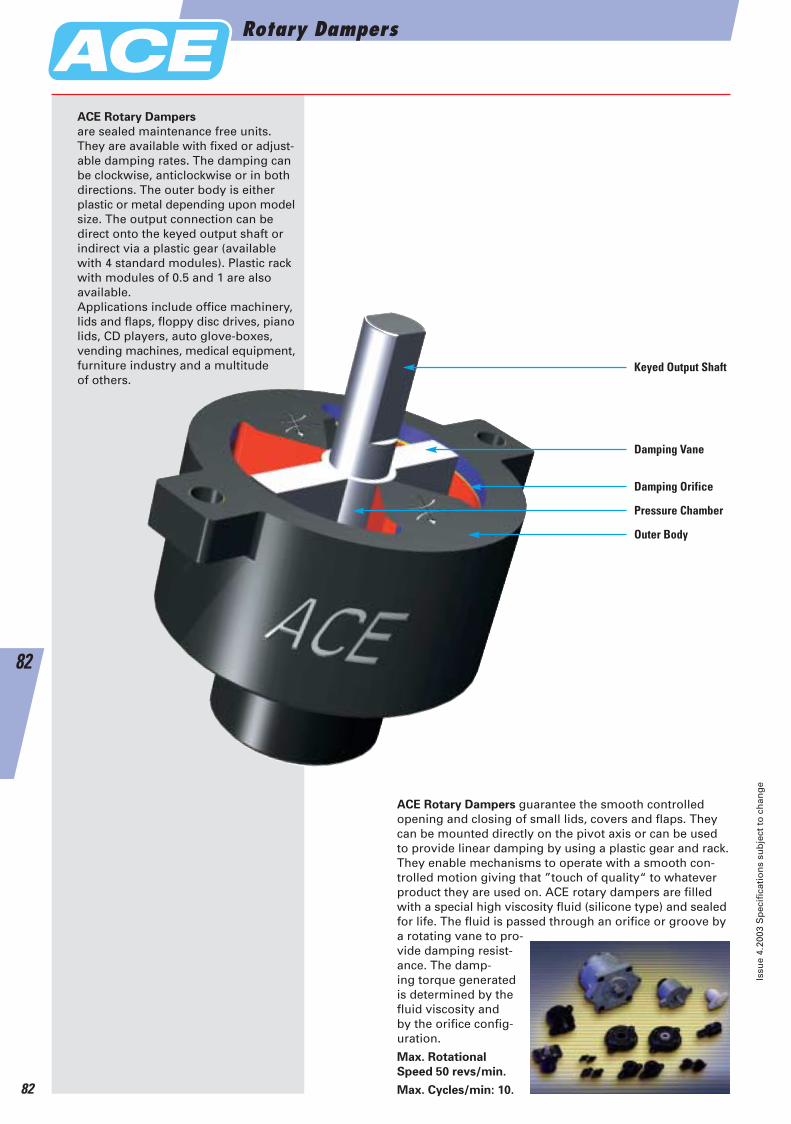
ACE Rotary Dampers
are sealed maintenance free units.They are available with fixed or adjust-able damping rates. The damping canbe clockwise, anticlockwise or in bothdirections. The outer body is either plastic or metal depending upon modelsize. The output connection can be direct onto the keyed output shaft or indirect via a plastic gear (available with 4 standard modules). Plastic rack with modules of 0.5 and 1 are also available.Applications include office machinery, lids and flaps, floppy disc drives, pianolids, CD players, auto glove-boxes, vending machines, medical equipment,furniture industry and a multitude of others.
ACE Rotary Dampers guarantee the smooth controlled opening and closing of small lids, covers and flaps. They can be mounted directly on the pivot axis or can be used to provide linear damping by using a plastic gear and rack. They enable mechanisms to operate with a smooth con-trolled motion giving that ”touch of quality“ to whatever product they are used on. ACE rotary dampers are filled with a special high viscosity fluid (silicone type) and sealedfor life. The fluid is passed through an orifice or groove by a rotating vane to pro-vide damping resist-ance. The damp-ing torque generatedis determined by thefluid viscosity and by the orifice config-uration.
Max. Rotational
Speed 50 revs/min.
Max. Cycles/min: 10.
Keyed Output Shaft
Damping Vane
Damping Orifice
Pressure Chamber
Outer Body
Rotary Dampers
Issu
e 4.
2003
Sp
ecif
icat
ion
s su
bje
ct t
o c
han
ge
82
82
ACE-Kat_2003_UK_080-085 22.09.2003 17:51 Uhr Seite 82
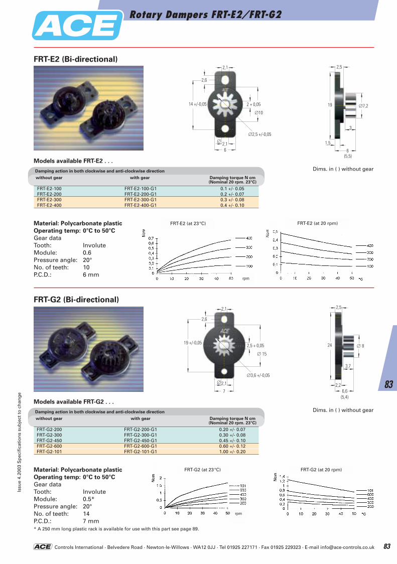
Controls International · Belvedere Road · Newton-le-Willows · WA12 0JJ · Tel 01925 227171 · Fax 01925 229323 · E-mail [email protected]
Material: Polycarbonate plastic
Operating temp: 0°C to 50°C
Gear dataTooth: InvoluteModule: 0.6Pressure angle: 20°No. of teeth: 10P.C.D.: 6 mm
14 +/-0,05 2 + 0,05
2,1
2,6
∅2,5 +/-0,05
∅10
2,16
∅
19
1,5
3
2,5
6
∅7,2
(5,5)
Damping action in both clockwise and anti-clockwise direction
without gear with gear Damping torque N cm(Nominal 20 rpm. 23°C)
FRT-E2-100 FRT-E2-100-G1 0.1 +/- 0.05FRT-E2-200 FRT-E2-200-G1 0.2 +/- 0.07FRT-E2-300 FRT-E2-300-G1 0.3 +/- 0.08FRT-E2-400 FRT-E2-400-G1 0.4 +/- 0.10
FRT-E2 (Bi-directional)
FRT-G2 (Bi-directional)
FRT-G2-200 FRT-G2-200-G1 0.20 +/- 0.07FRT-G2-300 FRT-G2-300-G1 0.30 +/- 0.08FRT-G2-450 FRT-G2-450-G1 0.45 +/- 0.10FRT-G2-600 FRT-G2-600-G1 0.60 +/- 0.12FRT-G2-101 FRT-G2-101-G1 1.00 +/- 0.20
2,6
19 +/-0,05
2,1
2,1
7
2,5 + 0,05
∅ 15
∅3,6 +/-0,05∅
∅ 824
2,2
3,7
2,5
6,6(5,4)
Models available FRT-E2 . . .
Damping action in both clockwise and anti-clockwise direction
without gear with gear Damping torque N cm(Nominal 20 rpm. 23°C)
Models available FRT-G2 . . .
Dims. in ( ) without gear
Dims. in ( ) without gear
FRT-E2 (at 23°C) FRT-E2 (at 20 rpm)
FRT-G2 (at 23°C) FRT-G2 (at 20 rpm)Material: Polycarbonate plastic
Operating temp: 0°C to 50°C
Gear dataTooth: InvoluteModule: 0.5*Pressure angle: 20°No. of teeth: 14P.C.D.: 7 mm* A 250 mm long plastic rack is available for use with this part see page 89.
rpm
rpm
Rotary Dampers FRT-E2/FRT-G2Is
sue
4.20
03 S
pec
ific
atio
ns
sub
ject
to
ch
ang
e
83
83
ACE-Kat_2003_UK_080-085 22.09.2003 17:52 Uhr Seite 83
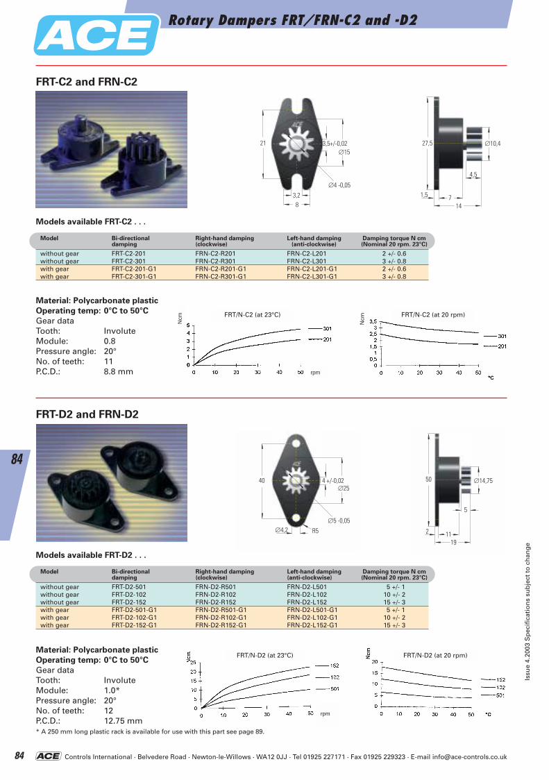
Controls International · Belvedere Road · Newton-le-Willows · WA12 0JJ · Tel 01925 227171 · Fax 01925 229323 · E-mail [email protected]
Models available FRT-C2 . . .
Material: Polycarbonate plastic
Operating temp: 0°C to 50°C
Gear dataTooth: InvoluteModule: 0.8Pressure angle: 20°No. of teeth: 11P.C.D.: 8.8 mm
∅1521 3,5+/-0,02
3,28
∅4 -0,05
∅10,427,5
1,5
4,5
714
FRT-C2 and FRN-C2
FRT-D2 and FRN-D2
Ncm
Ncm
Material: Polycarbonate plastic
Operating temp: 0°C to 50°C
Gear dataTooth: InvoluteModule: 1.0*Pressure angle: 20°No. of teeth: 12P.C.D.: 12.75 mm* A 250 mm long plastic rack is available for use with this part see page 89.
∅2540 4 +/-0,02
∅5 -0,05∅4,2 R5
∅14,7550
2
5
1119
Models available FRT-D2 . . .
Model Bi-directional Right-hand damping Left-hand damping Damping torque N cmdamping (clockwise) (anti-clockwise) (Nominal 20 rpm. 23°C)
without gear FRT-C2-201 FRN-C2-R201 FRN-C2-L201 2 +/- 0.6without gear FRT-C2-301 FRN-C2-R301 FRN-C2-L301 3 +/- 0.8with gear FRT-C2-201-G1 FRN-C2-R201-G1 FRN-C2-L201-G1 2 +/- 0.6with gear FRT-C2-301-G1 FRN-C2-R301-G1 FRN-C2-L301-G1 3 +/- 0.8
Model Bi-directional Right-hand damping Left-hand damping Damping torque N cmdamping (clockwise) (anti-clockwise) (Nominal 20 rpm. 23°C)
without gear FRT-D2-501 FRN-D2-R501 FRN-D2-L501 5 +/- 1without gear FRT-D2-102 FRN-D2-R102 FRN-D2-L102 10 +/- 2without gear FRT-D2-152 FRN-D2-R152 FRN-D2-L152 15 +/- 3with gear FRT-D2-501-G1 FRN-D2-R501-G1 FRN-D2-L501-G1 5 +/- 1with gear FRT-D2-102-G1 FRN-D2-R102-G1 FRN-D2-L102-G1 10 +/- 2with gear FRT-D2-152-G1 FRN-D2-R152-G1 FRN-D2-L152-G1 15 +/- 3
FRT/N-C2 (at 23°C) FRT/N-C2 (at 20 rpm)
FRT/N-D2 (at 23°C) FRT/N-D2 (at 20 rpm)
rpm
rpm
Rotary Dampers FRT/FRN-C2 and -D2
Issu
e 4.
2003
Sp
ecif
icat
ion
s su
bje
ct t
o c
han
ge
84
84
ACE-Kat_2003_UK_080-085 22.09.2003 17:53 Uhr Seite 84
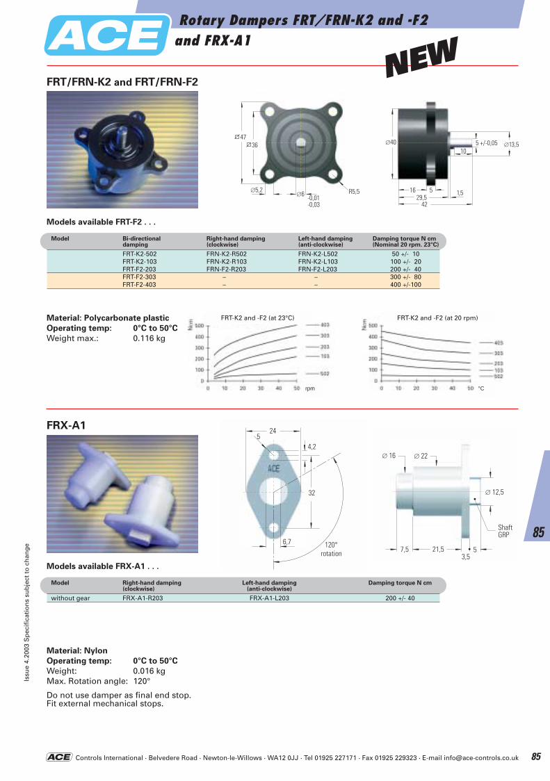
Controls International · Belvedere Road · Newton-le-Willows · WA12 0JJ · Tel 01925 227171 · Fax 01925 229323 · E-mail [email protected]
Material: Nylon
Operating temp: 0°C to 50°C
Weight: 0.016 kgMax. Rotation angle: 120°
Do not use damper as final end stop.Fit external mechanical stops.
-0,01-0,03
∅5,2∅6 R5,5
4736 5 +/-0,05∅40
51629,5
42
10
1,5
∅13,5
Material: Polycarbonate plastic
Operating temp: 0°C to 50°C
Weight max.: 0.116 kg
FRT/FRN-K2 and FRT/FRN-F2
FRX-A1
Models available FRT-F2 . . .
Model Bi-directional Right-hand damping Left-hand damping Damping torque N cmdamping (clockwise) (anti-clockwise) (Nominal 20 rpm. 23°C)
FRT-K2-502 FRN-K2-R502 FRN-K2-L502 50 +/- 10FRT-K2-103 FRN-K2-R103 FRN-K2-L103 100 +/- 20FRT-F2-203 FRN-F2-R203 FRN-F2-L203 200 +/- 40FRT-F2-303 – – 300 +/- 80FRT-F2-403 – – 400 +/-100
Models available FRX-A1 . . .
Model Right-hand damping Left-hand damping Damping torque N cm(clockwise) (anti-clockwise)
without gear FRX-A1-R203 FRX-A1-L203 200 +/- 40
FRT-K2 and -F2 (at 23°C) FRT-K2 and -F2 (at 20 rpm)
32
4,2
6,7
245
120°Schwenkwinkel 57,5 21,5
3,5
WelleGFK
∅ 12,5
∅ 16 ∅ 22
rotation
Shaft GRP
rpm °C
Rotary Dampers FRT/FRN-K2 and -F2and FRX-A1
Issu
e 4.
2003
Sp
ecif
icat
ion
s su
bje
ct t
o c
han
ge
85
85
NEW
ACE-Kat_2003_UK_080-085 22.09.2003 17:53 Uhr Seite 85
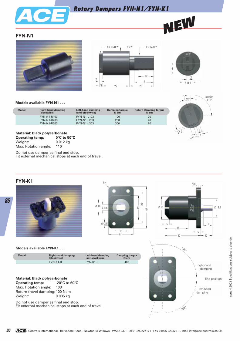
Controls International · Belvedere Road · Newton-le-Willows · WA12 0JJ · Tel 01925 227171 · Fax 01925 229323 · E-mail [email protected]
∅18,2∅ 26
26
10
540
5
13
3,8
∅ 10 6 -0,05
R 4
2735
45
1527
∅ 3,5
Material: Black polycarbonate
Operating temp: -20°C to 60°CMax. Rotation angle: 108°Return travel damping:100 NcmWeight: 0.035 kg
Do not use damper as final end stop.Fit external mechanical stops at each end of travel.
FYN-K1
rechtsdrehend
Endposition
linksdrehend
108°
108°
dämpfend
dämpfend
right-handdamping
End position
Models available FYN-K1 . . .
Model Right-hand damping Left-hand damping Damping torque(clockwise) (anti-clockwise) N cm
FYN-K1-R FYN-K1-L 400
1,2
110°20°
2
8-0,1
Schwenkwinkel
∅ 16-0,2
2216
3
2
20
∅ 20 ∅ 12-0,2
12 2
4
8-0,1
Material: Black polycarbonate
Operating temp: 0°C to 50°C
Weight: 0.012 kgMax. Rotation angle: 110°
Do not use damper as final end stop.Fit external mechanical stops at each end of travel.
left-handdamping
rotation
Models available FYN-N1 . . .
Model Right-hand damping Left-hand damping Damping torque Return Damping torque(clockwise) (anti-clockwise) N cm N cm
FYN-N1-R103 FYN-N1-L103 100 20FYN-N1-R203 FYN-N1-L203 200 40FYN-N1-R303 FYN-N1-L303 300 80
FYN-N1
Rotary Dampers FYN-N1/FYN-K1
Issu
e 4.
2003
Sp
ecif
icat
ion
s su
bje
ct t
o c
han
ge
86
86
NEW
ACE-Kat_2003_UK_086-091 22.09.2003 18:00 Uhr Seite 86
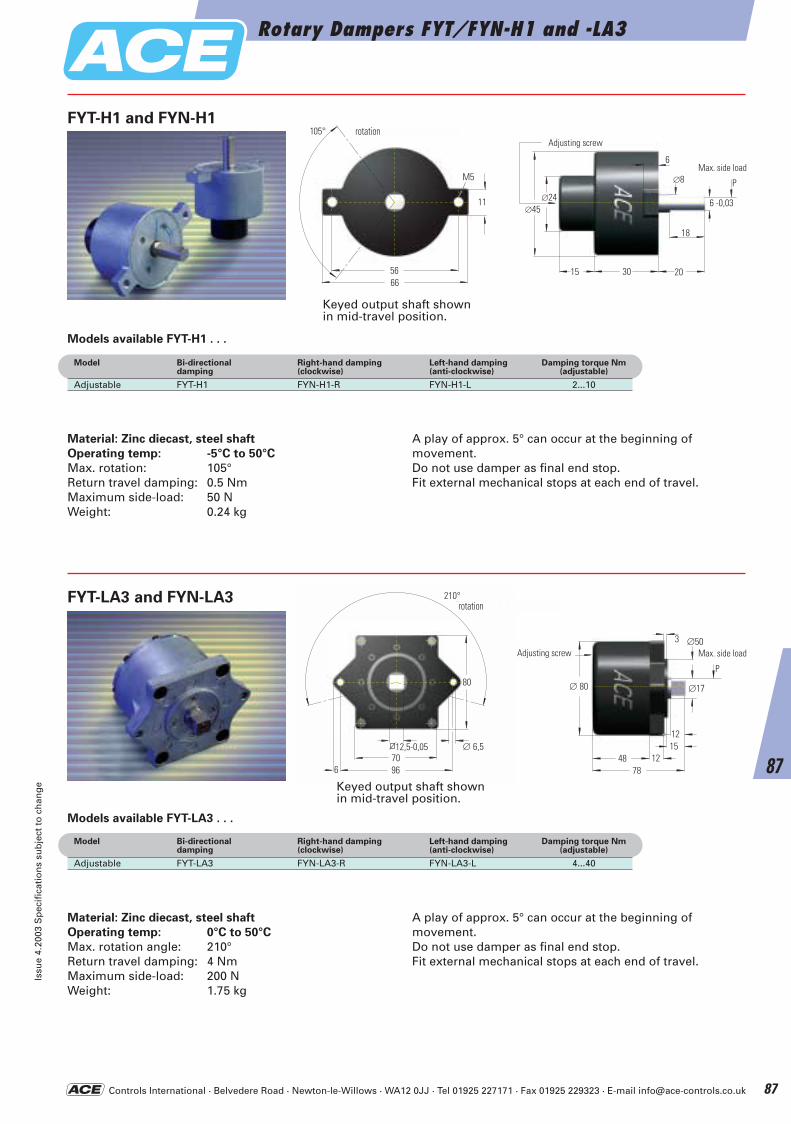
Controls International · Belvedere Road · Newton-le-Willows · WA12 0JJ · Tel 01925 227171 · Fax 01925 229323 · E-mail [email protected]
Rotary Dampers FYT/FYN-H1 and -LA3Is
sue
4.20
03 S
pec
ific
atio
ns
sub
ject
to
ch
ang
e
87
87
80
70966
∅ 6,512,5-0,05
210° Schwenkwinkel
11
5666
M5
105° Schwenkwinkel
6 -0,03∅45
2015 30
18
∅8
6
∅24P
Einstellschraube
∅17∅ 80
7848
3
121512
∅50
PEinstellschraube
Material: Zinc diecast, steel shaft
Operating temp: -5°C to 50°C
Max. rotation: 105°Return travel damping: 0.5 NmMaximum side-load: 50 NWeight: 0.24 kg
A play of approx. 5° can occur at the beginning of movement.Do not use damper as final end stop. Fit external mechanical stops at each end of travel.
Material: Zinc diecast, steel shaft
Operating temp: 0°C to 50°C
Max. rotation angle: 210°Return travel damping: 4 NmMaximum side-load: 200 NWeight: 1.75 kg
A play of approx. 5° can occur at the beginning of movement.Do not use damper as final end stop. Fit external mechanical stops at each end of travel.
FYT-H1 and FYN-H1
FYT-LA3 and FYN-LA3
Keyed output shaft shownin mid-travel position.
Keyed output shaft shownin mid-travel position.
Models available FYT-H1 . . .
Model Bi-directional Right-hand damping Left-hand damping Damping torque Nmdamping (clockwise) (anti-clockwise) (adjustable)
Adjustable FYT-H1 FYN-H1-R FYN-H1-L 2...10
Models available FYT-LA3 . . .
Model Bi-directional Right-hand damping Left-hand damping Damping torque Nmdamping (clockwise) (anti-clockwise) (adjustable)
Adjustable FYT-LA3 FYN-LA3-R FYN-LA3-L 4...40
Adjusting screwrotation
rotation
Adjusting screw Max. side load
Max. side load
ACE-Kat_2003_UK_086-091 22.09.2003 18:00 Uhr Seite 87
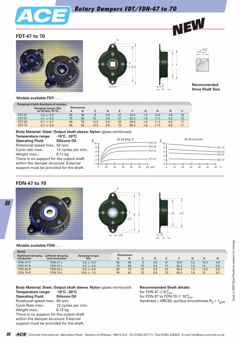
Controls International · Belvedere Road · Newton-le-Willows · WA12 0JJ · Tel 01925 227171 · Fax 01925 229323 · E-mail [email protected]
Body Material: Steel, Output shaft sleeve: Nylon (glass reinforced)Temperature range: -10°C...50°C
Operating Fluid: Silicone Oil
Rotational speed max.: 50 rpmCycle rate max.: 12 cycles per min.Weight max.: 0.11 kgThere is no support for the output shaftwithin the damper structure. Externalsupport must be provided for the shaft.
FDT-47 to 70
FDN-47 to 70
Damping in both directions of rotation
Damping torque, Nm(at 20 rpm, 23°C)
Dimensions
A B C D E F G H R V
FDT-47 2.0 +/- 0.3 65 56 8 4.5 47 42.8 1.6 10.3 4.5 10FDT-57 4.7 +/- 0.5 79 68 10 5.5 57 52.4 1.6 11.2 5.5 13FDT-63 6.7 +/- 0.7 89 76 12.5 6.5 63 58.6 1.6 11.3 6.5 17FDT-70 8.7 +/- 0.8 95 82 12.5 6.5 70 65.4 1.6 11.3 6.5 17
Models available FDT- . . .
Body Material: Steel, Output shaft sleeve: Nylon (glass reinforced)Temperature range: -10°C...50°C
Operating Fluid: Silicone Oil
Rotational speed max.: 50 rpmCycle Rate max.: 12 cycles per min.Weight max.: 0.12 kgThere is no support for the output shaft within the damper structure. External support must be provided for the shaft.
Recommended Shaft details:
for FDN-47 ∅ 6+0–0,03
for FDN-57 to FDN-70 ∅ 10+0–0,03
Hardness > HRC55, surface smoothness Rz < 1µm
Nm
U/min10 20 30 40 50 6000
2
4
6
8
10
FDT-47
FDT-57
FDT-63
FDT-70 Nm
°C10 20 30 40 50 6000
2
4
6
8
10
FDT-47
FDT-57FDT-63
FDT-70
rpm
Model
Righthand damping(clockwise)
Lefthand damping(anti-clockwise)
Damping torque Nm
Dimensions
A B C D E F G H R
FDN-47-R FDN-47-L 2.0 +/- 0.3 65 56 6 4.5 47 42.8 1.6 10.3 4.5FDN-57-R FDN-57-L 5.5 +/- 0.6 79 68 10 5.5 57 52.4 1.6 14 5.5FDN-63-R FDN-63-L 8.5 +/- 0.8 89 76 10 6.5 63 58.6 1.6 13.9 6.5FDN-70-R FDN-70-L 10.0 +/- 1.0 95 82 10 6.5 70 65.4 1.6 13 6.5
Models available FDN- . . .
ABC
R
D
F
H
E
G
AB
R
∅C
∅DH
∅E
G
∅F
Rotary Dampers FDT/FDN-47 to 70
Issu
e 4.
2003
Sp
ecif
icat
ion
s su
bje
ct t
o c
han
ge
88
88
C
∅V
-0,02-0,1
-0,10
Recommended
Drive Shaft Size
NEW
At 23 Deg. C At 20 rev/min.
ACE-Kat_2003_UK_086-091 22.09.2003 18:01 Uhr Seite 88
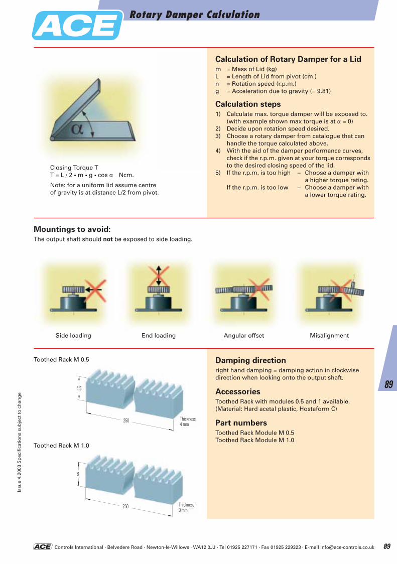
Controls International · Belvedere Road · Newton-le-Willows · WA12 0JJ · Tel 01925 227171 · Fax 01925 229323 · E-mail [email protected]
Damping direction
right hand damping = damping action in clockwise direction when looking onto the output shaft.
Accessories
Toothed Rack with modules 0.5 and 1 available.(Material: Hard acetal plastic, Hostaform C)
Part numbers
Toothed Rack Module M 0.5Toothed Rack Module M 1.0
250
4,5
Breite4 mm
250
9
Breite9 mm
Calculation of Rotary Damper for a Lid
m = Mass of Lid (kg)L = Length of Lid from pivot (cm.)n = Rotation speed (r.p.m.)g = Acceleration due to gravity (= 9.81)
Calculation steps
1) Calculate max. torque damper will be exposed to.(with example shown max torque is at a = 0)
2) Decide upon rotation speed desired.3) Choose a rotary damper from catalogue that can
handle the torque calculated above.4) With the aid of the damper performance curves,
check if the r.p.m. given at your torque correspondsto the desired closing speed of the lid.
5) If the r.p.m. is too high – Choose a damper with a higher torque rating.
If the r.p.m. is too low – Choose a damper with a lower torque rating.
Closing Torque TT = L / 2 · m · g · cos a Ncm.
Note: for a uniform lid assume centre of gravity is at distance L/2 from pivot.
Side loading End loading Angular offset Misalignment
Thickness9 mm
Thickness4 mm
Mountings to avoid:
The output shaft should not be exposed to side loading.
Toothed Rack M 0.5
Toothed Rack M 1.0
Rotary Damper CalculationIs
sue
4.20
03 S
pec
ific
atio
ns
sub
ject
to
ch
ang
e
89
89
ACE-Kat_2003_UK_086-091 22.09.2003 18:01 Uhr Seite 89
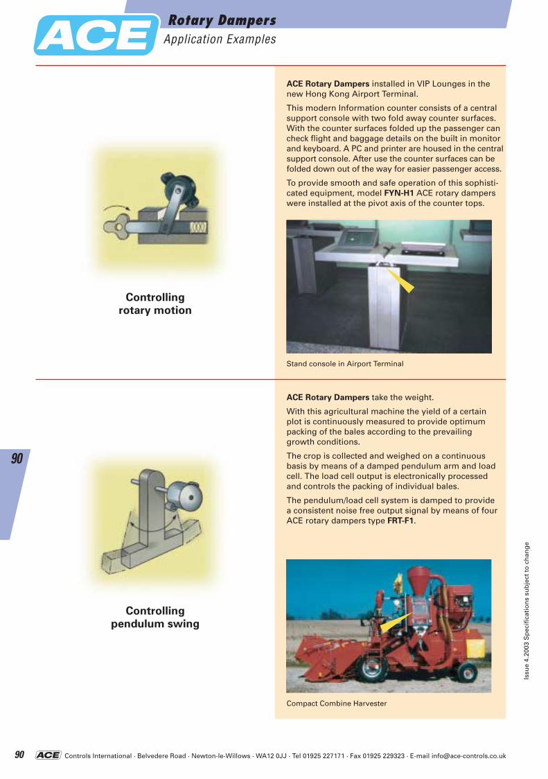
Controls International · Belvedere Road · Newton-le-Willows · WA12 0JJ · Tel 01925 227171 · Fax 01925 229323 · E-mail [email protected]
ACE Rotary Dampers take the weight.
With this agricultural machine the yield of a certain plot is continuously measured to provide optimumpacking of the bales according to the prevailing growth conditions.
The crop is collected and weighed on a continuous basis by means of a damped pendulum arm and loadcell. The load cell output is electronically processed and controls the packing of individual bales.
The pendulum/load cell system is damped to provide a consistent noise free output signal by means of fourACE rotary dampers type FRT-F1.
Controlling
rotary motion
Controlling
pendulum swing
ACE Rotary Dampers installed in VIP Lounges in thenew Hong Kong Airport Terminal.
This modern Information counter consists of a centralsupport console with two fold away counter surfaces.With the counter surfaces folded up the passenger cancheck flight and baggage details on the built in monitorand keyboard. A PC and printer are housed in the centralsupport console. After use the counter surfaces can befolded down out of the way for easier passenger access.
To provide smooth and safe operation of this sophisti-cated equipment, model FYN-H1 ACE rotary damperswere installed at the pivot axis of the counter tops.
Stand console in Airport Terminal
Compact Combine Harvester
Rotary DampersApplication Examples
Issu
e 4.
2003
Sp
ecif
icat
ion
s su
bje
ct t
o c
han
ge
90
90
ACE-Kat_2003_UK_086-091 22.09.2003 18:01 Uhr Seite 90
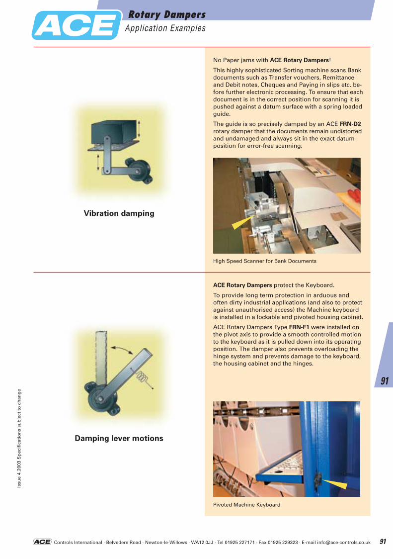
Controls International · Belvedere Road · Newton-le-Willows · WA12 0JJ · Tel 01925 227171 · Fax 01925 229323 · E-mail [email protected]
Damping lever motions
Vibration damping
No Paper jams with ACE Rotary Dampers!
This highly sophisticated Sorting machine scans Bank documents such as Transfer vouchers, Remittance and Debit notes, Cheques and Paying in slips etc. be-fore further electronic processing. To ensure that each document is in the correct position for scanning it is pushed against a datum surface with a spring loaded guide.
The guide is so precisely damped by an ACE FRN-D2
rotary damper that the documents remain undistorted and undamaged and always sit in the exact datum position for error-free scanning.
ACE Rotary Dampers protect the Keyboard.
To provide long term protection in arduous and often dirty industrial applications (and also to protect against unauthorised access) the Machine keyboard is installed in a lockable and pivoted housing cabinet.
ACE Rotary Dampers Type FRN-F1 were installed on the pivot axis to provide a smooth controlled motion to the keyboard as it is pulled down into its operating position. The damper also prevents overloading the hinge system and prevents damage to the keyboard, the housing cabinet and the hinges.
High Speed Scanner for Bank Documents
Pivoted Machine Keyboard
Rotary DampersApplication Examples
Issu
e 4.
2003
Sp
ecif
icat
ion
s su
bje
ct t
o c
han
ge
91
91
ACE-Kat_2003_UK_086-091 22.09.2003 18:01 Uhr Seite 91
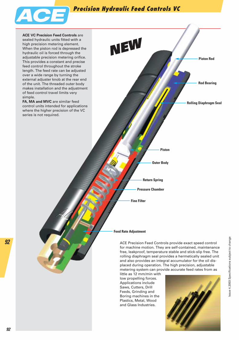
Precision Hydraulic Feed Controls VC
Issu
e 4.
2003
Sp
ecif
icat
ion
s su
bje
ct t
o c
han
ge
92
92 ACE Precision Feed Controls provide exact speed control for machine motion. They are self-contained, maintenancefree, leakproof, temperature stable and stick-slip free. Therolling diaphragm seal provides a hermetically sealed unitand also provides an integral accumulator for the oil dis-placed during operation. The high precision, adjustable metering system can provide accurate feed rates from as little as 12 mm/min with low propelling forces. Applications include Saws, Cutters, Drill Feeds, Grinding and Boring machines in the Plastics, Metal, Wood and Glass Industries.
Piston Rod
Rod Bearing
Rolling Diaphragm Seal
Piston
Outer Body
Return Spring
Pressure Chamber
Feed Rate Adjustment
Fine Filter
ACE VC Precision Feed Controls are sealed hydraulic units fitted with a high precision metering element. When the piston rod is depressed thehydraulic oil is forced through the adjustable precision metering orifice.This provides a constant and precisefeed control throughout the strokelength. The feed rate can be adjustedover a wide range by turning the external adjuster knob at the rear endof the unit. The threaded outer bodymakes installation and the adjustmentof feed control travel limits very simple.FA, MA and MVC are similar feed control units intended for applicationswhere the higher precision of the VCseries is not required.
NEW
ACE-Kat_2003_UK_092-097 23.09.2003 9:06 Uhr Seite 92
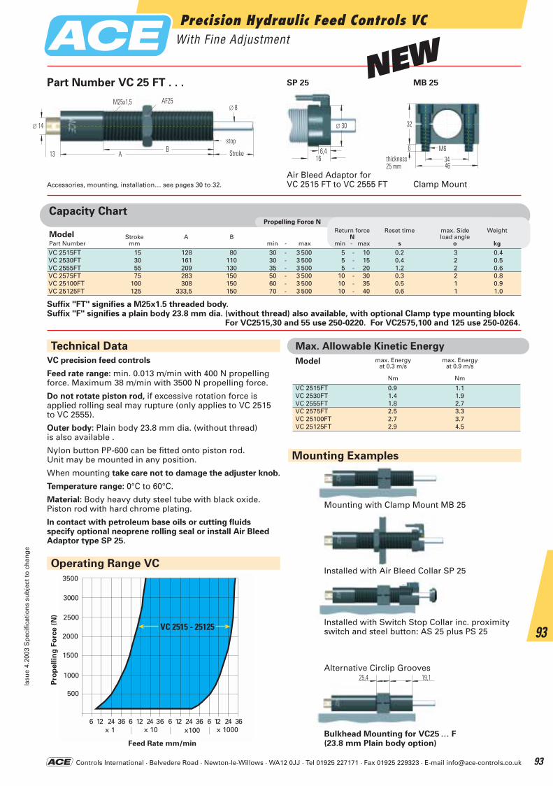
Controls International · Belvedere Road · Newton-le-Willows · WA12 0JJ · Tel 01925 227171 · Fax 01925 229323 · E-mail [email protected]
Precision Hydraulic Feed Controls VCWith Fine Adjustment
Issu
e 4.
2003
Sp
ecif
icat
ion
s su
bje
ct t
o c
han
ge
93
93
Operating Range VC
3500
3000
2500
2000
1500
1000
500
6 12 24 36 6 24 6 1212 2424 3636 36612x 1 x 10 x100 x 1000
VC 2515 - 25125
25,4 19,1
Mounting with Clamp Mount MB 25
Installed with Switch Stop Collar inc. proximityswitch and steel button: AS 25 plus PS 25
Bulkhead Mounting for VC25 … F(23.8 mm Plain body option)
Alternative Circlip Grooves
Technical Data
VC precision feed controls
Feed rate range: min. 0.013 m/min with 400 N propelling force. Maximum 38 m/min with 3500 N propelling force.
Do not rotate piston rod, if excessive rotation force is applied rolling seal may rupture (only applies to VC 2515 to VC 2555).
Outer body: Plain body 23.8 mm dia. (without thread) is also available .
Nylon button PP-600 can be fitted onto piston rod.Unit may be mounted in any position.
When mounting take care not to damage the adjuster knob.
Temperature range: 0°C to 60°C.
Material: Body heavy duty steel tube with black oxide. Piston rod with hard chrome plating.
In contact with petroleum base oils or cutting fluids specify optional neoprene rolling seal or install Air BleedAdaptor type SP 25.
Suffix "FT" signifies a M25x1.5 threaded body. Suffix "F" signifies a plain body 23.8 mm dia. (without thread) also available, with optional Clamp type mounting block
For VC2515,30 and 55 use 250-0220. For VC2575,100 and 125 use 250-0264.
Capacity ChartPropelling Force N
VC 2515FT 15 128 80 30 - 3 500 5 - 10 0.2 3 0.4VC 2530FT 30 161 110 30 - 3 500 5 - 15 0.4 2 0.5VC 2555FT 55 209 130 35 - 3 500 5 - 20 1.2 2 0.6VC 2575FT 75 283 150 50 - 3 500 10 - 30 0.3 2 0.8VC 25100FT 100 308 150 60 - 3 500 10 - 35 0.5 1 0.9VC 25125FT 125 333,5 150 70 - 3 500 10 - 40 0.6 1 1.0
Return force Reset time max. Side WeightModel Stroke A B N load anglePart Number mm min - max min - max s o kg
Part Number VC 25 FT . . . MB 25
Mounting Examples
Installed with Air Bleed Collar SP 25
∅ 30
6,416
∅ 14
AB
Hub13
Anschlagmöglich
∅ 8KM 25M25x1,5
4634
32
Breite25 mm
M66
Air Bleed Adaptor forVC 2515 FT to VC 2555 FTAccessories, mounting, installation… see pages 30 to 32. Clamp Mount
thickness25 mm
Stroke
stop
Pro
pellin
g F
orc
e (
N)
Feed Rate mm/min
AF25
SP 25
Max. Allowable Kinetic Energy
max. Energyat 0.3 m/s
Nm
max. Energyat 0.9 m/s
Nm
Model
VC 2515FT 0.9 1.1VC 2530FT 1.4 1.9VC 2555FT 1.8 2.7VC 2575FT 2.5 3.3VC 25100FT 2.7 3.7VC 25125FT 2.9 4.5
NEW
ACE-Kat_2003_UK_092-097 23.09.2003 9:06 Uhr Seite 93
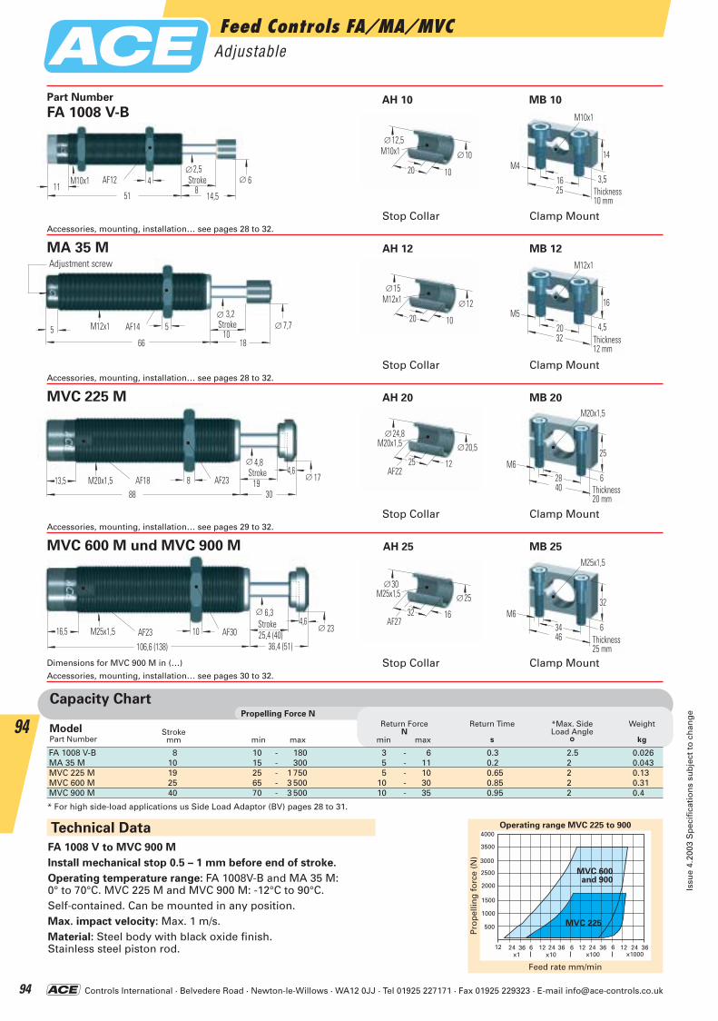
Controls International · Belvedere Road · Newton-le-Willows · WA12 0JJ · Tel 01925 227171 · Fax 01925 229323 · E-mail [email protected]
∅ 4,84,6
∅ 17M20x1,513,5 SW18 888
SW23 1930
HubAF18
StrokeAF23
∅ 6,34,6
∅ 23M25x1,516,5 SW23 10
106,6 (138)
SW30 25,4 (40)36,4 (51)
HubStrokeAF23 AF30
4 HubSW12851
M10x1
14,5
∅2,5∅ 6
11
M10x112,5
20 10
∅
10∅
25
14
3,5Breite10 mm
M10x1
M4
16
5 HubSW1410
66 18
∅ 3,2∅ 7,7M12x15
Einstellschraube
M12x115
20 10
∅
12∅
32
16
4,5Breite12 mm
M12x1
M5
20
M20x1,524,8
25 12
∅
SW22
20,5∅
40
25
6Breite20 mm
M20x1,5
M628
M25x1,530
32 16
∅
SW27
25∅
46
32
6Breite25 mm
M25x1,5
M634
Capacity ChartPropelling Force N
Strokemm
Return ForceN
Return Time
s
*Max. SideLoad Angle
°
Weight
kg
ModelPart Number min max min max
FA 1008 V-B 8 10 - 180 3 - 6 0.3 2.5 0.026MA 35 M 10 15 - 300 5 - 11 0.2 2 0.043MVC 225 M 19 25 - 1 750 5 - 10 0.65 2 0.13MVC 600 M 25 65 - 3 500 10 - 30 0.85 2 0.31MVC 900 M 40 70 - 3 500 10 - 35 0.95 2 0.4
* For high side-load applications us Side Load Adaptor (BV) pages 28 to 31.
Adjustment screw
Technical Data
FA 1008 V to MVC 900 M
Install mechanical stop 0.5 – 1 mm before end of stroke.
Operating temperature range: FA 1008V-B and MA 35 M: 0° to 70°C. MVC 225 M and MVC 900 M: -12°C to 90°C.Self-contained. Can be mounted in any position.Max. impact velocity: Max. 1 m/s.Material: Steel body with black oxide finish.Stainless steel piston rod.
Feed rate mm/min
Pro
pel
ling
fo
rce
(N)
Operating range MVC 225 to 900 4000
3500
2500
2000
3000
1500
1000
500
12 24 36 6 12 24 36 6 12 24 36 6 12 24 36x1 x10 x100 x1000
MVC 600and 900
MVC 225
Dimensions for MVC 900 M in (…)
FA 1008 V-B
MA 35 M AH 12 MB 12
MVC 225 M AH 20 MB 20
MVC 600 M und MVC 900 M AH 25 MB 25
Part Number
Stop Collar Clamp MountAccessories, mounting, installation… see pages 28 to 32.
Stop Collar Clamp MountAccessories, mounting, installation… see pages 28 to 32.
Stop Collar Clamp MountAccessories, mounting, installation… see pages 29 to 32.
Stop Collar Clamp MountAccessories, mounting, installation… see pages 30 to 32.
AH 10 MB 10
AF12 Stroke
AF14 Stroke
AF22
AF27
Thickness25 mm
Thickness20 mm
Thickness12 mm
Thickness10 mm
Feed Controls FA/MA/MVCAdjustable
Issu
e 4.
2003
Sp
ecif
icat
ion
s su
bje
ct t
o c
han
ge
94
94
ACE-Kat_2003_UK_092-097 23.09.2003 9:06 Uhr Seite 94
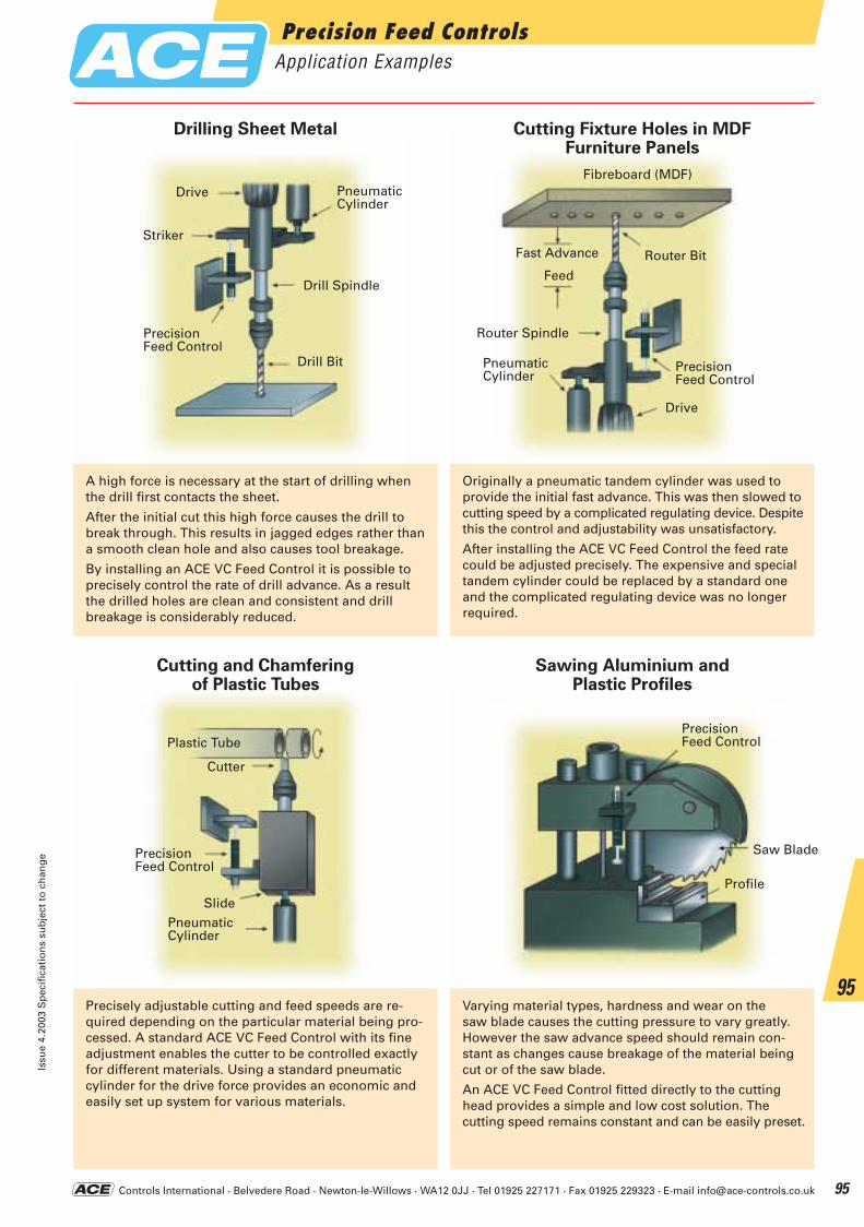
Controls International · Belvedere Road · Newton-le-Willows · WA12 0JJ · Tel 01925 227171 · Fax 01925 229323 · E-mail [email protected]
A high force is necessary at the start of drilling when the drill first contacts the sheet.
After the initial cut this high force causes the drill to break through. This results in jagged edges rather than a smooth clean hole and also causes tool breakage.
By installing an ACE VC Feed Control it is possible to precisely control the rate of drill advance. As a result the drilled holes are clean and consistent and drill breakage is considerably reduced.
Originally a pneumatic tandem cylinder was used to provide the initial fast advance. This was then slowed to cutting speed by a complicated regulating device. Despitethis the control and adjustability was unsatisfactory.
After installing the ACE VC Feed Control the feed rate could be adjusted precisely. The expensive and special tandem cylinder could be replaced by a standard one and the complicated regulating device was no longer required.
Precisely adjustable cutting and feed speeds are re-quired depending on the particular material being pro-cessed. A standard ACE VC Feed Control with its fineadjustment enables the cutter to be controlled exactlyfor different materials. Using a standard pneumatic cylinder for the drive force provides an economic andeasily set up system for various materials.
Varying material types, hardness and wear on the saw blade causes the cutting pressure to vary greatly.However the saw advance speed should remain con-stant as changes cause breakage of the material being cut or of the saw blade.
An ACE VC Feed Control fitted directly to the cutting head provides a simple and low cost solution. The cutting speed remains constant and can be easily preset.
Cutting and Chamfering of Plastic Tubes
Drilling Sheet Metal Cutting Fixture Holes in MDFFurniture Panels
Sawing Aluminium andPlastic Profiles
PneumaticCylinder
Drill Spindle
Drill Bit
PrecisionFeed Control
Striker
Drive
Router Bit
Router Spindle
PneumaticCylinder
Drive
Fibreboard (MDF)
Fast Advance
Feed
Plastic Tube
Cutter
SlidePneumaticCylinder
PrecisionFeed Control
PrecisionFeed Control
Saw Blade
Profile
PrecisionFeed Control
Precision Feed ControlsApplication Examples
Issu
e 4.
2003
Sp
ecif
icat
ion
s su
bje
ct t
o c
han
ge
95
95
ACE-Kat_2003_UK_092-097 23.09.2003 9:06 Uhr Seite 95
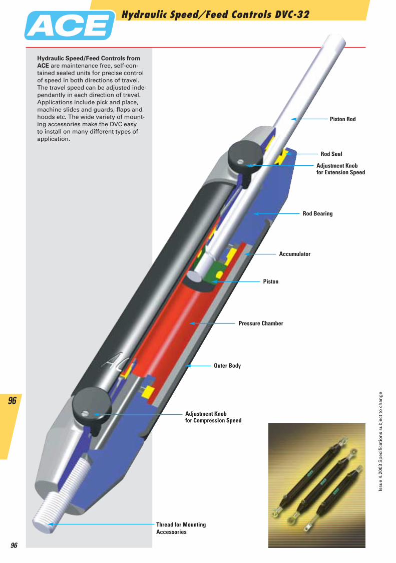
Hydraulic Speed/Feed Controls DVC-32
Issu
e 4.
2003
Sp
ecif
icat
ion
s su
bje
ct t
o c
han
ge
96
96
Piston Rod
Adjustment Knobfor Extension Speed
Rod Bearing
Accumulator
Piston
Pressure Chamber
Outer Body
Thread for Mounting Accessories
Rod Seal
Adjustment Knobfor Compression Speed
Hydraulic Speed/Feed Controls from
ACE are maintenance free, self-con-tained sealed units for precise control of speed in both directions of travel. The travel speed can be adjusted inde-pendantly in each direction of travel.Applications include pick and place,machine slides and guards, flaps andhoods etc. The wide variety of mount-ing accessories make the DVC easy to install on many different types of application.
ACE-Kat_2003_UK_092-097 23.09.2003 9:07 Uhr Seite 96

Controls International · Belvedere Road · Newton-le-Willows · WA12 0JJ · Tel 01925 227171 · Fax 01925 229323 · E-mail [email protected]
Speed/Feed Controls DVC-32Adjustable (Compression and Extension Forces 40 N to 2000 N)
Issu
e 4.
2003
Sp
ecif
icat
ion
s su
bje
ct t
o c
han
ge
97
97
36
32
24° ∅12 ∅8
8
16
∅16
6
12 3613
∅8
16
8
10 32
16
30M8x1,25
12
∅20 ∅13
15
16,5
36°
9
M8x1,25
8
30
20 L+/- 2 mm ausgefahren 20
∅ 14∅ 8,1
14 ∅8
∅ 8,1
HubKugelR 7
10 breit 10 breit
∅32 1420 22
∅ 1410
3000
2500
2000
1500
1000
500
00 250 500 750
DVC-32-50
DVC-32-100
DVC-32-150
1000
MaximumForce
Speed mm/sec
Compression speed control chart
Pro
pel
ling
Fo
rce
N
End Fitting Standard Dimensions End Fitting
Technical Data
Type Strokemm
L max.
A max.
B
DVC-32-50 50 240 42 2 000 42 2 000DVC-32-50-XX 50 250 75.2 42 2 000 42 2 000DVC-32-100 100 340 42 2 000 42 1 670DVC-32-100-XX 100 350 124.4 42 2 000 42 1 670DVC-32-150 150 440 42 2 000 42 1 335DVC-32-150-XX 150 450 173.6 42 2 000 42 1 335
Propelling Force N(Extension) (Compression)min. max. min. max.
Dimensions
ACE speed/feed controls are self-contained and maintenance free.Mechanical stops: Provide mechanical stop 1 to 1.5 mm before end of each stroke direction.Mounting position: Can be mounted in any position.To special order: Special oils and external finishes. Uni-directional damping (free flow in reverse direction). NOTE: End fittings should
be secured with Loctite or similiar.Operating temperature: 0°C to 65°C.Operating fluid: Automatic Transmission Fluid (ATF) 42cSt. at 40°CMaterial: Body: black anodised aluminium. Piston rod: hard chromeplated steel. End fittings: zinc plated steel.
3000
2500
2000
1500
1000
500
00 250 500 750 1000
offen3/4 offen1/2 offen1/4 offenMax. Vorschubkraft bei Einstellung
1250
Tension speed control chart
Speed mm/sec
Pro
pel
ling
Fo
rce
N
1/4 open 1/2 open 3/4 open open
E8
A8
B8
C8
D8
DIN 71802 C8
DIN 71752 D8
DIN 648 E8
A8
B8
(Max. permitted force 1200 N)
BallR 7
L+/-2 mm extendedStroke
10 thick10 thick
6,4 A max
∅ 13
∅ 8
∅ 6
B ∅32
∅ 141030 30
∅ 6
12,7 breit
10
12,7 thick
A max.
Fixed End Fitting -XX
Ordering Example DVC-32-50-DD-P
Type (DVC speed/feed controller)Body ø (32 mm)Stroke (50 mm)Piston rod end fitting (D = Clevis fork)Body end fitting (D = Clevis fork)Damping direction (P = Both directions)
Damping OptionsP = Damping in both directions (Standard Model)M = Damping on out stroke
(Adjustment knob at ”rear end“ free flow)N = Damping on in stroke
(Adjustment knob at ”piston rod end“ free flow)
The end fittings are interchangeable (except the fixed end version,detailed below) and must be positively secured by the customer to prevent unscrewing (i.e. Loctite). For mounting accessories please see page 123.
ACE-Kat_2003_UK_092-097 23.09.2003 9:07 Uhr Seite 97
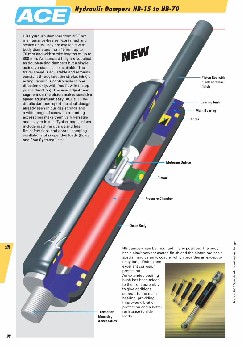
Hydraulic Dampers HB-15 to HB-70
Issu
e 4.
2003
Sp
ecif
icat
ion
s su
bje
ct t
o c
han
ge
98
98 HB dampers can be mounted in any position. The bodyhas a black powder coated finish and the piston rod has aspecial hard ceramic coating which provides an exceptio-nally long lifetime andexcellent corrosion protection.An extended bearingbush has been added to the front assembly to give additional support to the main bearing, providing improved vibration protection and a betterresistance to side loads.
Piston Rod withblack ceramicfinish
Bearing bush
Main Bearing
Piston
Pressure Chamber
Outer Body
Thread forMountingAccessories
Seals
Metering Orifice
HB Hydraulic dampers from ACE aremaintenance-free self-contained andsealed units.They are available withbody diameters from 15 mm up to 70 mm and with stroke lengths of up to800 mm. As standard they are suppliedas doubleacting dampers but a singleacting version is also available. The travel speed is adjustable and remainsconstant throughout the stroke. (singleacting version is controllable in one direction only, with free flow in the op-posite direction). The new adjustment
segment on the piston makes sensitive
speed adjustment easy. ACE’s HB hy-draulic dampers sport the sleek designalready seen in our gas springs and a wide range of screw on mounting accessories make them very versatileand easy to install. Typical applications include machine guards and lids,fire safety flaps and doors , damping oscillations of suspended loads (Powerand Free Systems ) etc.
NEW
ACE-Kat_2003_UK_098-103 23.09.2003 9:11 Uhr Seite 98
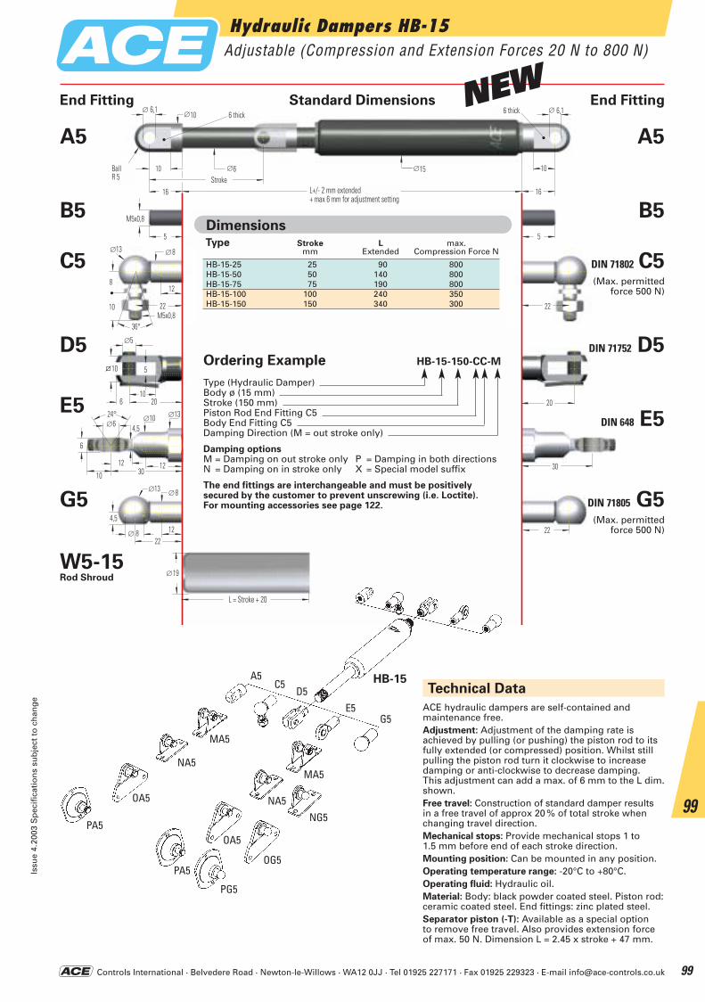
Controls International · Belvedere Road · Newton-le-Willows · WA12 0JJ · Tel 01925 227171 · Fax 01925 229323 · E-mail [email protected]
Hydraulic Dampers HB-15Adjustable (Compression and Extension Forces 20 N to 800 N)
Issu
e 4.
2003
Sp
ecif
icat
ion
s su
bje
ct t
o c
han
ge
99
99
2222
4,5
∅13 ∅8
12∅ 8
30
2024° ∅10
∅6
6
∅5
10
5
6 20
10
5
M5x0,8
5
22
∅10∅ 6,1
10
16 L+/- 2 mm ausgefahren+ max 6 mm Verstellweg
∅6
∅ 6,1
HubKugelR 5
6 breit
16
6 breit
∅15 10
22M5x0,8
8
∅13 ∅8
12
10
36°
L = Hub + 20
∅19
12
∅13
4,5
10 3012
End Fitting Standard Dimensions End Fitting
Ordering Example HB-15-150-CC-M
Type (Hydraulic Damper)Body ø (15 mm)Stroke (150 mm)Piston Rod End Fitting C5Body End Fitting C5Damping Direction (M = out stroke only)
Damping optionsM = Damping on out stroke only P = Damping in both directionsN = Damping on in stroke only X = Special model suffix
The end fittings are interchangeable and must be positively secured by the customer to prevent unscrewing (i.e. Loctite).For mounting accessories see page 122.
Type Stroke L max.mm Extended Compression Force N
HB-15-25 25 90 800HB-15-50 50 140 800HB-15-75 75 190 800HB-15-100 100 240 350HB-15-150 150 340 300
Dimensions
PA5
OA5
NA5
MA5
NG5
G5
A5C5
D5E5
OG5
PG5
PA5
OA5
NA5
MA5
HB-15
E5
DIN 71805 G5G5
A5
B5
C5
D5
DIN 71802 C5
DIN 71752 D5
DIN 648 E5
A5
B5
W5-15Rod Shroud
Technical Data
ACE hydraulic dampers are self-contained and maintenance free.Adjustment: Adjustment of the damping rate is achieved by pulling (or pushing) the piston rod to itsfully extended (or compressed) position. Whilst stillpulling the piston rod turn it clockwise to increasedamping or anti-clockwise to decrease damping.This adjustment can add a max. of 6 mm to the L dim.shown.Free travel: Construction of standard damper results in a free travel of approx 20 % of total stroke when changing travel direction.Mechanical stops: Provide mechanical stops 1 to 1.5 mm before end of each stroke direction.Mounting position: Can be mounted in any position.Operating temperature range: -20°C to +80°C.Operating fluid: Hydraulic oil.Material: Body: black powder coated steel. Piston rod:ceramic coated steel. End fittings: zinc plated steel.Separator piston (-T): Available as a special option to remove free travel. Also provides extension forceof max. 50 N. Dimension L = 2.45 x stroke + 47 mm.
(Max. permitted force 500 N)
(Max. permitted force 500 N)
BallR 5
L+/- 2 mm extended+ max 6 mm for adjustment setting
Stroke
L = Stroke + 20
6 thick 6 thickNEW
ACE-Kat_2003_UK_098-103 23.09.2003 9:11 Uhr Seite 99

Controls International · Belvedere Road · Newton-le-Willows · WA12 0JJ · Tel 01925 227171 · Fax 01925 229323 · E-mail [email protected]
Hydraulic Dampers HB-22Adjustable (Compression and Extension Forces 30 N to 1800 N)
Issu
e 4.
2003
Sp
ecif
icat
ion
s su
bje
ct t
o c
han
ge
100
100
3030
6
∅20 ∅13
15∅ 13
36
3224° ∅12
∅8
8
16
∅16
6
12 3613
∅8
16
8
10 32
16
30M8x1,25
12
∅20 ∅13
15
16,5
36°
9
M8x1,25
8
30
20 L+/- 2 mm ausgefahren+ max 6 mm Verstellweg
20
∅ 14∅ 8,1
14 ∅8
∅ 8,1
HubKugelR 7
10 breit 10 breit
∅22 14
L = Hub + 30
∅28
End Fitting Standard Dimensions End Fitting
Ordering Example HB-22-150-DD-M
Type (Hydraulic Damper)Body ø (22 mm)Stroke (150 mm)Piston Rod End Fitting D8Body End Fitting D8Damping Direction (M = out stroke only)
Damping OptionsM = Damping on out stroke only P = Damping in both directionsN = Damping on in stroke only X = Special model suffix
The end fittings are interchangeable and must be positively secured by the customer to prevent unscrewing (i.e. Loctite).For mounting accessories see page 123.
Type Stroke L max.mm Extended Compression Force N
HB-22-50 50 150 1 800HB-22-100 100 250 1 800HB-22-150 150 350 1 800HB-22-200 200 450 1 000HB-22-250 250 550 1 000
Dimensions
HB-22
E8
G8
A8
B8
C8
D8
DIN 71802 C8
DIN 71752 D8
DIN 648 E8
DIN 71805 G8
A8
B8
W8-22Rod Shroud
Technical Data
ACE hydraulic dampers are self-contained and maintenance free.Adjustment: Adjustment of the damping rate is achieved by pulling (or pushing) the piston rod to itsfully extended (or compressed) position. Whilst stillpulling the piston rod turn it clockwise to increasedamping and anti-clockwise to decrease damping.This adjustment can add a maximum of 6 mm to theL dimension shown.Free travel: Construction of standard damper results in a free travel of approx. 20 % of stroke.Mechanical stops: Provide mechanical stops 1 to 1.5 mm before end of each stroke direction.Mounting position: Can be mounted in any position.Operating temperature range: -20°C to +80°C.Operating fluid: Hydraulic oil.Material: Body: powder coated steel. Piston rod: ceramic coated steel. End fittings: zinc plated steel.Separator piston (-T): Available as a special option to remove free travel. Also provides extension forceof max. 100 N. Dimension L = 2.38 x stroke + 55 mm.
(Max. permitted force 1200 N)
(Max. permitted force 1200 N)
PA8
OA8
NA8
MA8
NG8
G8
A8C8
D8E8
OG8
PG8
PE8
OE8
NE8
ME8E8
BallR 7
L+/- 2 mm extended+ max 6 mm for adjustment setting
Stroke
10 thick 10 thick
L = Stroke + 30
NEW
ACE-Kat_2003_UK_098-103 23.09.2003 9:11 Uhr Seite 100
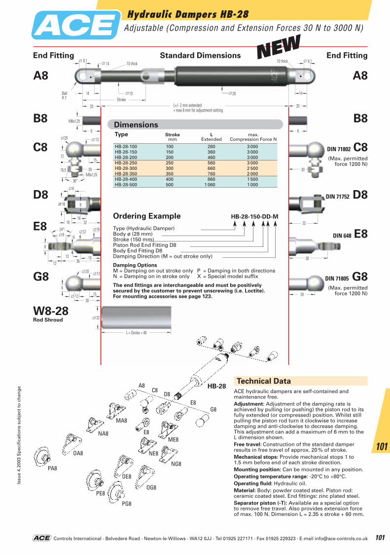
Controls International · Belvedere Road · Newton-le-Willows · WA12 0JJ · Tel 01925 227171 · Fax 01925 229323 · E-mail [email protected]
Hydraulic Dampers HB-28Adjustable (Compression and Extension Forces 30 N to 3000 N)
Issu
e 4.
2003
Sp
ecif
icat
ion
s su
bje
ct t
o c
han
ge
101
101
30
36
32
30
6
∅20 ∅13
15∅ 13
24° ∅12 ∅8
8
16
∅16
6
12 3613
∅8
16
8
10 32
16
30M8x1,25
12
∅20 ∅13
15
16,5
36°
9
M8x1,25
8
30
20 L+/- 2 mm ausgefahren+ max 6 mm Verstellweg
20
L = Hub + 40
∅32
∅ 14∅ 8,1
14 ∅10
∅ 8,1
HubKugelR 7
10 breit 10 breit
∅28 14
End Fitting Standard Dimensions End Fitting
Ordering Example HB-28-150-DD-M
Type (Hydraulic Damper)Body ø (28 mm)Stroke (150 mm)Piston Rod End Fitting D8Body End Fitting D8Damping Direction (M = out stroke only)
Damping OptionsM = Damping on out stroke only P = Damping in both directionsN = Damping on in stroke only X = Special model suffix
The end fittings are interchangeable and must be positively secured by the customer to prevent unscrewing (i.e. Loctite).For mounting accessories see page 123.
Type Stroke L max.mm Extended Compression Force N
HB-28-100 100 260 3 000HB-28-150 150 360 3 000HB-28-200 200 460 3 000HB-28-250 250 560 3 000HB-28-300 300 660 2 500HB-28-350 350 760 2 000HB-28-400 400 860 1 500HB-28-500 500 1 060 1 000
Dimensions
HB-28
DIN 648 E8E8
G8
A8
B8
C8
D8
DIN 71802 C8
DIN 71752 D8
DIN 71805 G8
A8
B8
W8-28Rod Shroud
Technical Data
ACE hydraulic dampers are self-contained and maintenance free.Adjustment: Adjustment of the damping rate is achieved by pulling (or pushing) the piston rod to itsfully extended (or compressed) position. Whilst stillpulling the piston rod turn it clockwise to increasedamping and anti-clockwise to decrease damping.This adjustment can add a maximum of 6 mm to theL dimension shown.Free travel: Construction of the standard damper results in free travel of approx. 20 % of stroke.Mechanical stops: Provide mechanical stops 1 to 1.5 mm before end of each stroke direction.Mounting position: Can be mounted in any position.Operating temperature range: -20°C to +80°C.Operating fluid: Hydraulic oil.Material: Body: powder coated steel. Piston rod: ceramic coated steel. End fittings: zinc plated steel.Separator piston (-T): Available as a special option to remove free travel. Also provides extension forceof max. 100 N. Dimension L = 2.35 x stroke + 60 mm.
(Max. permitted force 1200 N)
(Max. permitted force 1200 N)
PA8
OA8
NA8
MA8
NG8
G8
A8C8
D8E8
OG8
PG8
PE8
OE8
NE8
ME8E8
BallR 7
L+/- 2 mm extended+ max 6 mm for adjustment setting
Stroke
10 thick 10 thick
L = Stroke + 40
NEW
ACE-Kat_2003_UK_098-103 23.09.2003 9:12 Uhr Seite 101
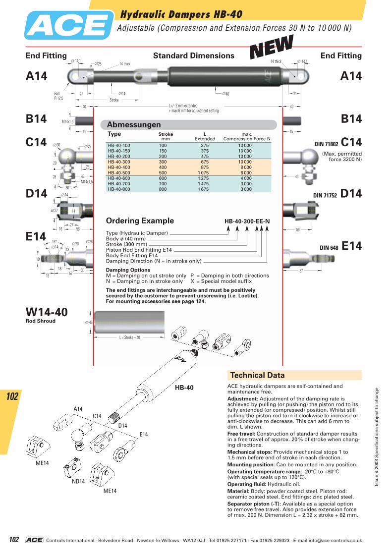
Controls International · Belvedere Road · Newton-le-Willows · WA12 0JJ · Tel 01925 227171 · Fax 01925 229323 · E-mail [email protected]
Hydraulic Dampers HB-40Adjustable (Compression and Extension Forces 30 N to 10 000 N)
Issu
e 4.
2003
Sp
ecif
icat
ion
s su
bje
ct t
o c
han
ge
102
102
45M14x1,5
20
∅30 ∅22
25
28
36°
45
56
∅14
27
14
16 56
27
57
16° ∅20 ∅14
19
30
∅26
13
18 5718
15
M14x1,5
15
40 L+/- 2 mm ausgefahren+ max 6 mm Verstellweg
40
∅25∅ 14,1
21 ∅14
∅ 14,1
HubKugelR 12,5
14 breit 14 breit
∅40 21
L = Hub + 40
∅ 45
End Fitting Standard Dimensions End Fitting
ACE hydraulic dampers are self-contained and maintenance free.Adjustment: Adjustment of the damping rate is achieved by pulling (or pushing) the piston rod to its fully extended (or compressed) position. Whilst still pulling the piston rod turn it clockwise to increase or anti-clockwise to decrease. This can add 6 mm to dim. L shown.Free travel: Construction of standard damper resultsin a free travel of approx. 20 % of stroke when chang-ing directions.Mechanical stops: Provide mechanical stops 1 to 1.5 mm before end of stroke in each direction.Mounting position: Can be mounted in any position.Operating temperature range: -20°C to +80°C (with special seals up to 120°C).Operating fluid: Hydraulic oil.Material: Body: powder coated steel. Piston rod: ceramic coated steel. End fittings: zinc plated steel.Separator piston (-T): Available as a special option to remove free travel. Also provides extension forceof max. 200 N. Dimension L = 2.32 x stroke + 82 mm.
Technical Data
Ordering Example HB-40-300-EE-N
Type (Hydraulic Damper)Body ø (40 mm)Stroke (300 mm)Piston Rod End Fitting E14Body End Fitting E14Damping Direction (N = in stroke only)
Damping OptionsM = Damping on out stroke only P = Damping in both directionsN = Damping on in stroke only X = Special model suffix
The end fittings are interchangeable and must be positively secured by the customer to prevent unscrewing (i.e. Loctite).For mounting accessories see page 124.
Type Stroke L max.mm Extended Compression Force N
HB-40-100 100 275 10 000HB-40-150 150 375 10 000HB-40-200 200 475 10 000HB-40-300 300 675 10 000HB-40-400 400 875 8 000HB-40-500 500 1 075 6 000HB-40-600 600 1 275 4 000HB-40-700 700 1 475 3 000HB-40-800 800 1 675 3 000
Abmessungen
HB-40
E14
A14
B14
C14
D14
DIN 71802 C14
DIN 71752 D14
DIN 648 E14
A14
B14
W14-40Rod Shroud
(Max. permitted force 3200 N)
ME14
A14C14
D14E14
ND14
ME14
BallR 12,5
L+/- 2 mm extended+ max 6 mm for adjustment setting
Stroke
14 thick 14 thick
L = Stroke + 40
NEW
ACE-Kat_2003_UK_098-103 23.09.2003 9:12 Uhr Seite 102
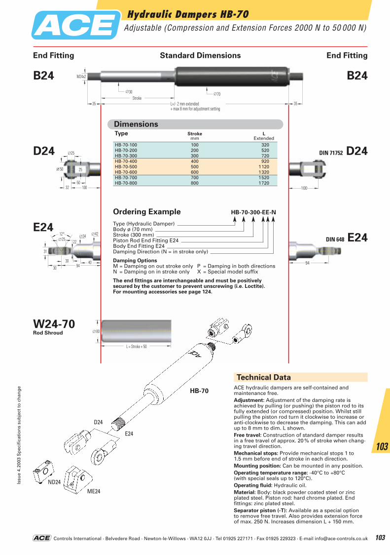
Controls International · Belvedere Road · Newton-le-Willows · WA12 0JJ · Tel 01925 227171 · Fax 01925 229323 · E-mail [email protected]
Hydraulic Dampers HB-70Adjustable (Compression and Extension Forces 2000 N to 50 000 N)
Issu
e 4.
2003
Sp
ecif
icat
ion
s su
bje
ct t
o c
han
ge
103
103
100
∅25
50
25
32 100
50
94
12° ∅34 ∅25
31
∅42
40
22
30 9430
35 L+/- 2 mm ausgefahren+ max 8mm Verstellweg
∅30Hub
∅70
M24x2
35
L = Hub + 50
∅80
ACE hydraulic dampers are self-contained and maintenance free.Adjustment: Adjustment of the damping rate is achieved by pulling (or pushing) the piston rod to its fully extended (or compressed) position. Whilst still pulling the piston rod turn it clockwise to increase or anti-clockwise to decrease the damping. This can addup to 8 mm to dim. L shown.Free travel: Construction of standard damper resultsin a free travel of approx. 20 % of stroke when chang-ing travel direction.Mechanical stops: Provide mechanical stops 1 to 1.5 mm before end of stroke in each direction.Mounting position: Can be mounted in any position.Operating temperature range: -40°C to +80°C (with special seals up to 120°C).Operating fluid: Hydraulic oil.Material: Body: black powder coated steel or zinc plated steel. Piston rod: hard chrome plated. End fittings: zinc plated steel.Separator piston (-T): Available as a special option to remove free travel. Also provides extension forceof max. 250 N. Increases dimension L + 150 mm.
Technical Data
ME24
D24
E24
ND24
HB-70
End Fitting Standard Dimensions End Fitting
Ordering Example HB-70-300-EE-N
Type (Hydraulic Damper)Body ø (70 mm)Stroke (300 mm)Piston Rod End Fitting E24Body End Fitting E24Damping Direction (N = in stroke only)
Damping OptionsM = Damping on out stroke only P = Damping in both directionsN = Damping on in stroke only X = Special model suffix
The end fittings are interchangeable and must be positively secured by the customer to prevent unscrewing (i.e. Loctite).For mounting accessories see page 124.
Type Stroke Lmm Extended
HB-70-100 100 320HB-70-200 200 520HB-70-300 300 720HB-70-400 400 920HB-70-500 500 1120HB-70-600 600 1320HB-70-700 700 1520HB-70-800 800 1720
Dimensions
E24
B24
D24 DIN 71752 D24
DIN 648 E24
B24
W24-70Rod Shroud
L+/- 2 mm extended+ max 8 mm for adjustment setting
Stroke
L = Stroke + 50
ACE-Kat_2003_UK_098-103 23.09.2003 9:12 Uhr Seite 103
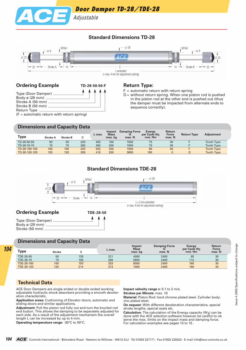
Controls International · Belvedere Road · Newton-le-Willows · WA12 0JJ · Tel 01925 227171 · Fax 01925 229323 · E-mail [email protected]
Stroke B C
TD-28-50-50 50 50 220 402 150 1550 75 30 F Tooth TypeTD-28-70-70 70 70 260 482 200 1500 70 30 F Tooth TypeTD-28-100-100 100 100 220 502 250 1500 80 40 F Tooth TypeTD-28-120-120 120 120 208 410 250 3800 165 0 D Tooth Type
Damping ForceQ
max. NL max.
ImpactMass
max. kg
Energy per Cycle W3
max. Nm
ReturnForce
max. NReturn Type Adjustment
Dimensions and Capacity Data
Stroke AType
C
Damping ForceQ
max. NL max.
ImpactMass
max. kg
Energy per Cycle W3
max. Nm
ReturnForce
max. N
Dimensions and Capacity Data
StrokeType
Technical Data
ACE Door Dampers are single ended or double ended working adjustable hydraulic shock absorbers providing a smooth deceler-ation characteristic.Application areas: Cushioning of Elevator doors, automatic and sliding doors and similar applications.Adjustment: Pull the piston rod fully out and turn the knurled rod end button. This allows the damping to be separately adjusted for each side. As a result of the adjustment mechanism the overall length L can be increased by up to 4 mm.Operating temperature range: -30°C to 50°C.
Impact velocity range v: 0.1 to 2 m/s.Strokes per Minute: max. 10Material: Piston Rod: hard chrome plated steel. Cylinder body: zinc plated steel.On request: With different deceleration characteristics, special stroke lengths, special seals etc.Calculation: The calculation of the Energy capacity (W3) can be done with the ACE selection software however be careful to observe the max. limits on the impact mass and damping force. For calculation examples see pages 13 to 15 .
∅ 28
C14
∅ 23
25
∅ 8M16x1
Hub A 14
∅ 23
M16x1∅ 8
25L ausgefahren
(+ max. 4 mm Verstellweg)
Hub B
∅ 28
C14
∅ 23
25
∅ 8M16x1
HubL ± 2 mm ausgefahren
(+ max. 4 mm Verstellweg)
Standard Dimensions TD-28
Standard Dimensions TDE-28
Ordering Example TD-28-50-50-F
Type (Door Damper)Body ø (28 mm)Stroke A (50 mm)Stroke B (50 mm)Return Type(F = automatic return with return spring)
Return Type:F = automatic return with return springD = without return spring. When one piston rod is pushed
in the piston rod at the other end is pushed out (thusthe damper must be impacted from alternate ends tosequence correctly).
Ordering Example TDE-28-50
Type (Door Damper)Body ø (28 mm)Stroke (50 mm)
TDE-28-50 50 130 221 4000 2400 80 30TDE-28-70 70 158 269 5600 2400 112 30TDE-28-100 100 193 333 8000 2400 160 30TDE-28-120 120 214 373 7000 2400 190 40
Door Damper TD-28/TDE-28Adjustable
Issu
e 4.
2003
Sp
ecif
icat
ion
s su
bje
ct t
o c
han
ge
104
104
L extended(+ max. 4 mm for adjustment setting)
Stroke A
L ± 2 mm extended(+ max. 4 mm for adjustment setting)
Stroke
Stroke B
ACE-Kat_2003_UK_104-109 23.09.2003 9:15 Uhr Seite 104
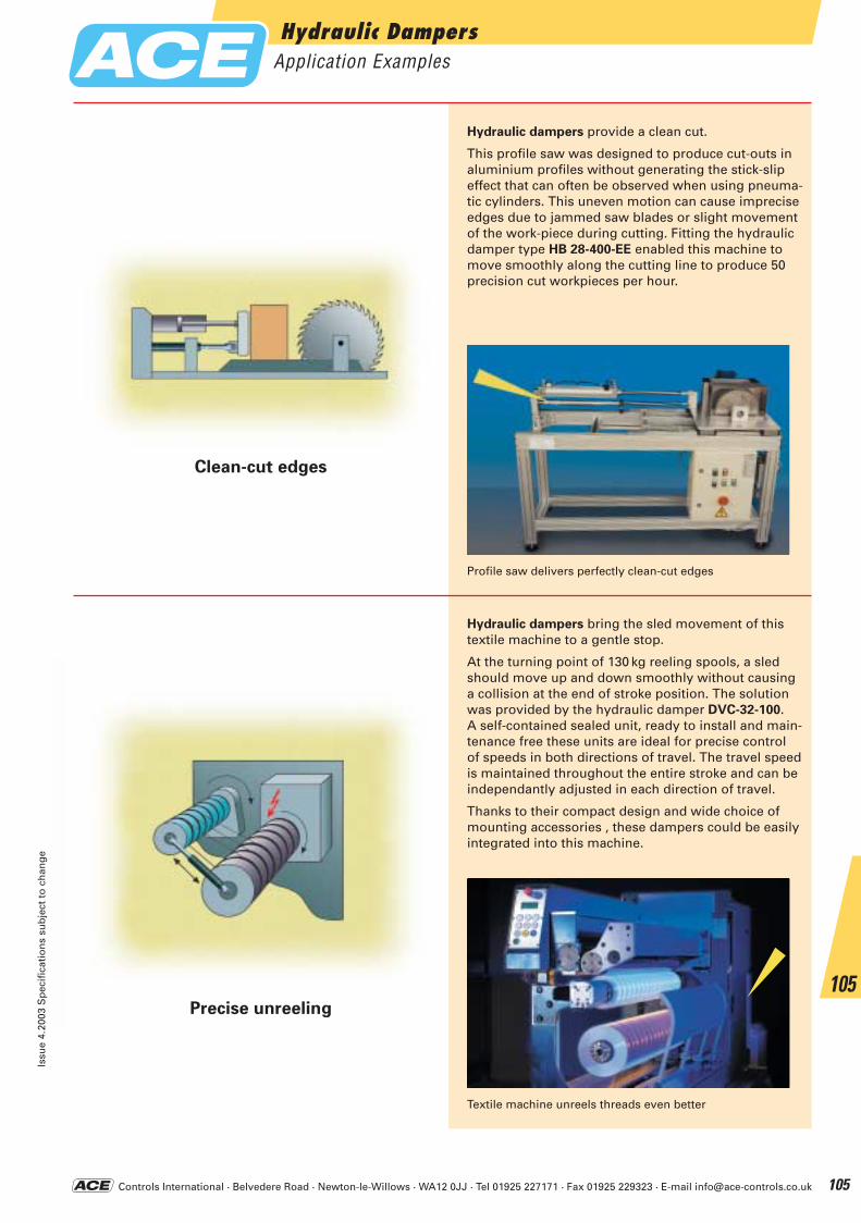
Controls International · Belvedere Road · Newton-le-Willows · WA12 0JJ · Tel 01925 227171 · Fax 01925 229323 · E-mail [email protected]
Hydraulic Dampers Application Examples
Issu
e 4.
2003
Sp
ecif
icat
ion
s su
bje
ct t
o c
han
ge
105
105
Hydraulic dampers bring the sled movement of this textile machine to a gentle stop.
At the turning point of 130 kg reeling spools, a sledshould move up and down smoothly without causing a collision at the end of stroke position. The solutionwas provided by the hydraulic damper DVC-32-100. A self-contained sealed unit, ready to install and main-tenance free these units are ideal for precise control of speeds in both directions of travel. The travel speedis maintained throughout the entire stroke and can beindependantly adjusted in each direction of travel.
Thanks to their compact design and wide choice ofmounting accessories , these dampers could be easilyintegrated into this machine.
Profile saw delivers perfectly clean-cut edges
Textile machine unreels threads even better
Clean-cut edges
Precise unreeling
Hydraulic dampers provide a clean cut.
This profile saw was designed to produce cut-outs inaluminium profiles without generating the stick-slipeffect that can often be observed when using pneuma-tic cylinders. This uneven motion can cause impreciseedges due to jammed saw blades or slight movementof the work-piece during cutting. Fitting the hydraulicdamper type HB 28-400-EE enabled this machine tomove smoothly along the cutting line to produce 50precision cut workpieces per hour.
ACE-Kat_2003_UK_104-109 23.09.2003 9:15 Uhr Seite 105
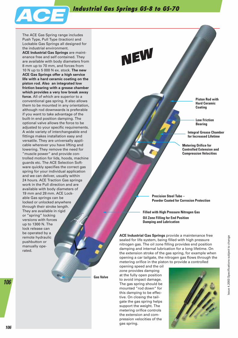
Industrial Gas Springs GS-8 to GS-70
Issu
e 4.
2003
Sp
ecif
icat
ion
s su
bje
ct t
o c
han
ge
106
106
ACE Industrial Gas Springs provide a maintenance free sealed for life system, being filled with high pressure nitrogen gas. The oil zone filling provides end position damping and internal lubrication for a long lifetime. On the extension stroke of the gas spring, for example when opening a car tailgate, the nitrogen gas flows through the metering orifice in the piston to provide a controlled opening speed and the oil zone provides damping at the fully open position to avoid impact damage. The gas spring should be mounted ”rod down“ for this damping to be effec-tive. On closing the tail-gate the gas spring helpssupport the weight. The metering orifice controls the extension and com-pression velocities of the gas spring.
Filled with High Pressure Nitrogen Gas
Oil Zone Filling for End PositionDamping and Lubrication
Gas Valve
Piston Rod withHard Ceramic Coating
Precision Steel Tube –Powder Coated for Corrosion Protection
Metering Orifice for Controlled Extension and Compression Velocities
Integral Grease Chamber for Increased Lifetime
The ACE Gas Spring range includesPush Type, Pull Type (traction) andLockable Gas Springs all designed forthe industrial environment.ACE Industrial Gas Springs are maint-enance free and self contained. They are available with body diameters from8 mm up to 70 mm, and forces from10 N up to 5 000 N ex. stock. The new
ACE Gas Springs offer a high service
life with a hard ceramic coating on the
piston rod. Also an integrated low
friction bearing with a grease chamber
which provides a very low break away
force. All of which are superior to aconventional gas spring. It also allows them to be mounted in any orientation, although rod downwards is preferable if you want to take advantage of the built-in end position damping. The optional valve allows the force to beadjusted to your specific requirements.A wide variety of interchangeable endfittings makes installation easy andversatile. They are universally appli-cable wherever you have lifting and lowering. They remove the need for ”muscle power“ and provide con-trolled motion for lids, hoods, machineguards etc. The ACE Selection Soft-ware quickly specifies the correct gas spring for your individual application and we can deliver, usually within 24 hours. ACE Traction Gas springswork in the Pull direction and areavailable with body diameters of19 mm and 28 mm. ACE Lock-able Gas springs can belocked or unlocked anywherethrough their stroke length.They are available in rigidor ”spring“ locking versions with forcesup to 1300 N. Thelock release canbe operated by aremote hydraulicpushbutton ormanually ope-rated.
Low FrictionBearing
NEW
ACE-Kat_2003_UK_104-109 23.09.2003 9:15 Uhr Seite 106
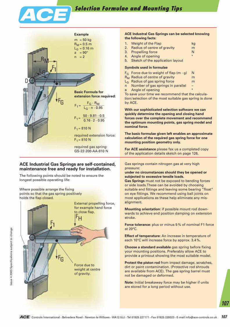
External propelling force, for example hand force to close flap.
Force due to weight at centre of gravity.
Where possible arrange the fixing points so that the gas spring positively holds the flap closed.
Controls International · Belvedere Road · Newton-le-Willows · WA12 0JJ · Tel 01925 227171 · Fax 01925 229323 · E-mail [email protected]
ACE Industral Gas Springs can be selected knowing
the following facts:
1. Weight of the Flap kg2. Radius of centre of gravity m3. Propelling force N4. Angle of opening °5. Sketch of the application layout
Symbols used in formulae
FG Force due to weight of flap (m · g) NRM Radius of centre of gravity mLG Radius of gas spring force mn Number of gas springs in parallel –a Angle of opening °To save your time we recommend that the calcula-tion/selection of the most suitable gas spring is doneby ACE.
With our sophisticated selection software we can
quickly determine the opening and closing hand
forces over the complete movement and recommend
the optimum mounting points, gas spring model and
nominal force.
The basic formulae given left enables an approximate
calculation of the required gas spring force for one
mounting position geometry only.
For ACE assistance please fax us a completed copyof the application details sketch on page 126.
Gas springs contain nitrogen gas at very high pressure: under no circumstances should they be opened or
subjected to excessive tensile loads.
Gas Springs must not be exposed to bending forces or side loads.These can be avoided by choosing suitable end fittings and leaving some bearing ”float“on eye fittings. We recommend using ball joints onmost applications as these help eliminate any mis-alignment.
Mounting orientation: if possible mount rod down-wards to achieve end position damping on extension stroke.
Force tolerance: plus or minus 5 % of nominal F1 forceat 20°C.
Effect of temperature: An increase in temperature ofeach 10°C will increase force by approx. 3.4 %.
Choose a standard available gas spring before fixingyour mounting positions. Preferably allow ACE to provide a printout showing the most suitable model.
Protect the piston rod from impact damage, scratches,dirt or paint contamination. (Protective rod shrouds are available from ACE). The gas spring barrel must not be damaged or deformed.
Note: Initial breakaway force may be higher if units are stored for a long period without use.
ACE Industrial Gas Springs are self-contained, maintenance free and ready for installation.
The following points should be noted to ensure the longest possible operating life:
Example
m = 50 kgRM = 0.5 mLG = 0.16 ma = 90°n = 2
F1 =
F1 = 810 N
required extension force:F1 = 810 N
required gas spring:GS-22-200-AA-810 N
50 · 9.81 · 0.50.16 · 2 · 0.95
F1 =FG · RM
LG · n · 0.95
Basic Formula for
extension force required:
Selection Formulae and Mounting TipsIs
sue
4.20
03 S
pec
ific
atio
ns
sub
ject
to
ch
ang
e
107
107
ACE-Kat_2003_UK_104-109 23.09.2003 9:16 Uhr Seite 107
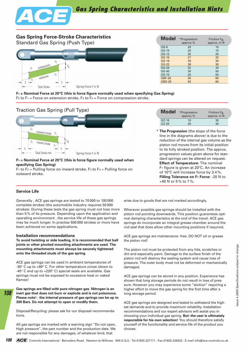
Controls International · Belvedere Road · Newton-le-Willows · WA12 0JJ · Tel 01925 227171 · Fax 01925 229323 · E-mail [email protected]
Gas Spring Characteristics and Installation Hints
Issu
e 4.
2003
Sp
ecif
icat
ion
s su
bje
ct t
o c
han
ge
108
108
GS-8 28 10GS-10 20 10GS-12 25 20GS-15 27 20GS-19 33 30GS-22 38 30GS-28 52 40GS-40 30 50GS-70 25 50GBF-28 50 60GBS-28 50 60
Model *Progression Friction FRapprox.% approx. in N
GZ-19 10 30GZ-28 20 40
Model *Progression Friction FRapprox.% approx. in N
einfahrend
55Gesamthub mm
F1
F3
F4
F2
FR
ausfahrend
Nutzhub mm
ausziehen
55Gesamthub mm
F2
F4
F3
F1
FR
Nutzhub mm
einziehen
F1 = Nominal Force at 20°C (this is force figure normally used when specifying Gas Spring)
F2 to F1 = Force on extension stroke. F3 to F4 = Force on compression stroke.
Traction Gas Spring (Pull Type)
Gas Spring Force-Stroke Characteristics
Standard Gas Spring (Push Type)
F1 = Nominal Force at 20°C (this is force figure normally used when
specifying Gas Spring)
F1 to F2 = Pulling force on inward stroke. F3 to F4 = Pulling force on outward stroke.
* The Progression (the slope of the forceline in the diagrams above) is due to thereduction of the internal gas volume as thepiston rod moves from its initial positionto its fully stroked position. The approx.progression values given above for stan-dard springs can be altered on request.Effect of Temperature: The nominal F1 figure is given at 20°C. An increase of 10°C will increase force by 3.4 %.Filling Tolerance on F1 Force: -20 N to+40 N or 5 % to 7 %.
Service Life
Generally , ACE gas springs are tested to 70 000 to 100 000complete strokes (the automobile industry requires 50 000strokes). During these tests the gas spring must not lose morethan 5 % of its pressure. Depending upon the application andoperating environment , the service life of these gas springsmay be much longer. In practise 500 000 strokes or more havebeen achieved on some applications.
Installation recommendationsTo avoid twisting or side loading, it is recommended that ball
joints or other pivoted mounting attachments are used. The
mounting attachments must always be securely tightened
onto the threaded studs of the gas spring.
ACE gas springs can be used in ambient temperatures of -30° C up to +80° C. For other temperature zones (down to -45° C and up to +220° C) special seals are available. Gassprings must not be exposed to excessive heat or naked flames!
Gas springs are filled with pure nitrogen gas. Nitrogen is an
inert gas that does not burn or explode and is not poisonous.
Please note! : the internal pressure of gas springs can be up to
300 Bars. Do not attempt to open or modify them.
Disposal/Recycling: please ask for our disposal recommenda-tions.
All gas springs are marked with a warning sign ”Do not open,High pressure”, the part number and the production date. Weare not responsible for any damages, of whatever kind, that
arise due to goods that are not marked accordingly.
Wherever possible gas springs should be installed with thepiston rod pointing downwards. This position guarantees opti-mal damping characteristics at the end of the travel. ACE gassprings do incorporate an integral grease chamber around therod seal that does allow other mounting positions if required.
ACE gas springs are maintenance -free. DO NOT oil or greasethe piston rod!
The piston rod must be protected from any hits, scratches ordirt and especially paint. Damage to the surface finish of thepiston rod will destroy the sealing system and cause loss ofpressure. The outer body must not be deformed or mechanicallydamaged.
ACE gas springs can be stored in any position. Experience hasshown that long storage periods do not result in loss of pres-sure. However you may experience some ”stiction” requiring ahigher effort to move the gas spring for the first time after along storage period.
ACE gas springs are designed and tested to withstand the high-est demands and to provide maximum reliability. Installation recommendations and our expert advisors will assist you inchoosing your individual gas spring. But: the user is ultimately
responsible for his own selection! You should therefore satisfyyourself of the functionality and service life of the product youchoose.
Spring Force F in N
Spring Force F in N
Total Stroke
compression
extension
Total Stroke mm
outward stroke
inward stroke
ACE-Kat_2003_UK_104-109 23.09.2003 9:16 Uhr Seite 108
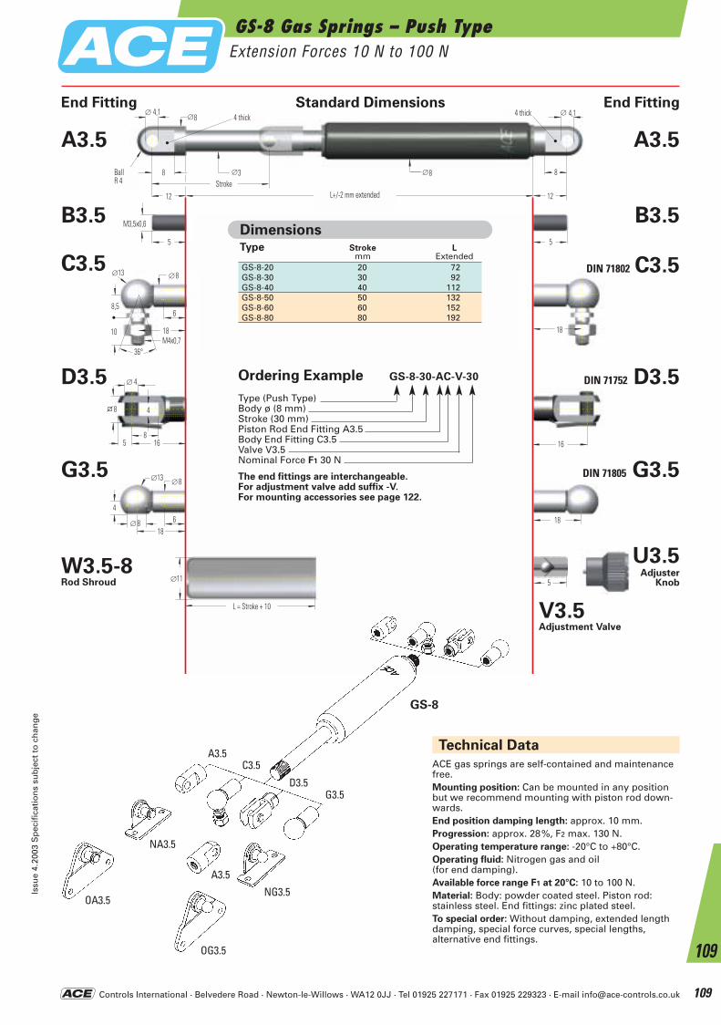
Controls International · Belvedere Road · Newton-le-Willows · WA12 0JJ · Tel 01925 227171 · Fax 01925 229323 · E-mail [email protected]
GS-8 Gas Springs – Push TypeExtension Forces 10 N to 100 N
Issu
e 4.
2003
Sp
ecif
icat
ion
s su
bje
ct t
o c
han
ge
109
109
18
4
∅13 ∅8
6∅ 8 18
16
∅ 4
8
4
5 16
8
5
M3,5x0,6
5
18
∅8∅ 4,1
8
12 L+/- 2 mm ausgefahren
∅3
∅ 4,1
HubKugelR 4
4 breit
12
4 breit
∅8 8
18M4x0,7
8,5
∅13 ∅8
6
10
36°
5
L = Hub + 10
∅11
Technical Data
ACE gas springs are self-contained and maintenance free.Mounting position: Can be mounted in any position but we recommend mounting with piston rod down-wards.End position damping length: approx. 10 mm.Progression: approx. 28%, F2 max. 130 N.Operating temperature range: -20°C to +80°C.Operating fluid: Nitrogen gas and oil (for end damping).Available force range F1 at 20°C: 10 to 100 N.Material: Body: powder coated steel. Piston rod: stainless steel. End fittings: zinc plated steel.To special order: Without damping, extended length damping, special force curves, special lengths, alternative end fittings.
OA3.5
NA3.5
NG3.5
G3.5
A3.5C3.5
D3.5
OG3.5
A3.5
GS-8
End Fitting Standard Dimensions End Fitting
Type Strokemm
L Extended
GS-8-20 20 72GS-8-30 30 92GS-8-40 40 112GS-8-50 50 132GS-8-60 60 152GS-8-80 80 192
Dimensions
G3.5
A3.5
B3.5
C3.5
D3.5
DIN 71802 C3.5
DIN 71752 D3.5
DIN 71805 G3.5
A3.5
B3.5
U3.5Adjuster
Knob
W3.5-8Rod Shroud
V3.5Adjustment Valve
BallR 4
L+/-2 mm extendedStroke
L = Stroke + 10
4 thick 4 thick
Ordering Example GS-8-30-AC-V-30
Type (Push Type)Body ø (8 mm)Stroke (30 mm)Piston Rod End Fitting A3.5Body End Fitting C3.5Valve V3.5Nominal Force F1 30 N
The end fittings are interchangeable.For adjustment valve add suffix -V. For mounting accessories see page 122.
ACE-Kat_2003_UK_104-109 23.09.2003 9:16 Uhr Seite 109
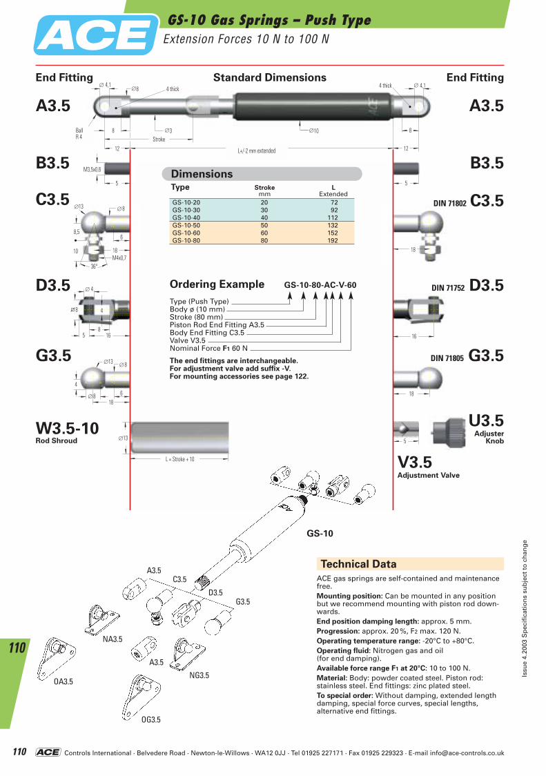
Controls International · Belvedere Road · Newton-le-Willows · WA12 0JJ · Tel 01925 227171 · Fax 01925 229323 · E-mail [email protected]
Technical Data
18
4
∅13 ∅8
6∅ 8 18
16
∅ 4
8
4
5 16
8
5
M3,5x0,6
5
18
∅8∅ 4,1
8
12 L+/- 2 mm ausgefahren
∅3
∅ 4,1
HubKugelR 4
4 breit
12
4 breit
∅10 8
18M4x0,7
8,5
∅13 ∅8
6
10
36°
5
L = Hub + 10
∅13
ACE gas springs are self-contained and maintenance free.Mounting position: Can be mounted in any position but we recommend mounting with piston rod down-wards.End position damping length: approx. 5 mm.Progression: approx. 20 %, F2 max. 120 N.Operating temperature range: -20°C to +80°C.Operating fluid: Nitrogen gas and oil (for end damping).Available force range F1 at 20°C: 10 to 100 N.Material: Body: powder coated steel. Piston rod: stainless steel. End fittings: zinc plated steel.To special order: Without damping, extended length damping, special force curves, special lengths, alternative end fittings.
End Fitting Standard Dimensions End Fitting
Type Strokemm
L Extended
GS-10-20 20 72GS-10-30 30 92GS-10-40 40 112GS-10-50 50 132GS-10-60 60 152GS-10-80 80 192
Dimensions
GS-10
G3.5
A3.5
B3.5
C3.5
D3.5
DIN 71802 C3.5
DIN 71752 D3.5
DIN 71805 G3.5
A3.5
B3.5
U3.5Adjuster
Knob
W3.5-10Rod Shroud
V3.5 Adjustment Valve
OA3.5
NA3.5
NG3.5
G3.5
A3.5C3.5
D3.5
OG3.5
A3.5
GS-10 Gas Springs – Push TypeExtension Forces 10 N to 100 N
Issu
e 4.
2003
Sp
ecif
icat
ion
s su
bje
ct t
o c
han
ge
110
110
BallR 4
L+/-2 mm extended
Stroke
L = Stroke + 10
4 thick 4 thick
Ordering Example GS-10-80-AC-V-60
Type (Push Type)Body ø (10 mm)Stroke (80 mm)Piston Rod End Fitting A3.5Body End Fitting C3.5Valve V3.5Nominal Force F1 60 N
The end fittings are interchangeable.For adjustment valve add suffix -V. For mounting accessories see page 122.
ACE-Kat_2003_UK_110-115 23.09.2003 9:22 Uhr Seite 110

Controls International · Belvedere Road · Newton-le-Willows · WA12 0JJ · Tel 01925 227171 · Fax 01925 229323 · E-mail [email protected]
GS-12 Gas Springs – Push TypeExtension Forces 10 N to 180 N
Issu
e 4.
2003
Sp
ecif
icat
ion
s su
bje
ct t
o c
han
ge
111
111
Technical Data
18
4
∅13 ∅8
6∅ 8 18
16
∅4
8
4
5 16
8
5
M3,5x0,6
5
18
∅8∅ 4,1
8
12 L+/- 2 mm ausgefahren
∅4
∅ 4,1
HubKugelR 4
4 breit
12
4 breit
∅12 8
18M4x0,7
8,5
∅13 ∅8
6
10
36°
5
L = Hub + 10
∅15
Type Stroke L Max. F1
mm ExtendedGS-12-20 20 72 180 NGS-12-40 40 112 180 NGS-12-50 50 132 180 NGS-12-60 60 152 180 NGS-12-80 80 192 150 NGS-12-100 100 232 150 NGS-12-120 120 272 120 NGS-12-150 150 332 100 N
Dimensions
End Fitting Standard Dimensions End Fitting
ACE gas springs are self-contained and maintenance free.Mounting position: can be mounted in any position but we recommend mounting with the piston roddownwards so that the damping is effective at end of extension stroke.End position damping length: approx. 10 mm.Progression: approx. 25 %, F2 max. 225 N.Operating temperature range: -20°C to +80°C.Operating fluid: Nitrogen gas and oil (for end damping).Available force range F1 at 20°C: 10 to 180 N.Material: Body: powder coated steel. Piston rod: stainless steel. End fittings: zinc plated steel.To special order: Without damping, extended length damping, special force curves, special lengths (max.150 mm stroke), alternative end fittings.
GS-12
G3.5
A3.5
B3.5
C3.5
D3.5
DIN 71802 C3.5
DIN 71752 D3.5
DIN 71805 G3.5
A3.5
B3.5
U3.5Adjuster
Knob
W3.5-12Rod Shroud
V3.5 Adjustment Valve
OA3,5
NA3,5
NG3,5
G3,5
A3,5C3,5
D3,5
OG3,5
A3,5
BallR 4
L+/-2 mm ausgefahren Stroke
L = Stroke + 10
4 thick 4 thick
Ordering Example GS-12-100-AA-V-30
Type (Push Type)Body ø (12 mm)Stroke (100 mm)Piston Rod End Fitting A3.5Body End Fitting A3.5Valve V3.5Nominal Force F1 30 N
The end fittings are interchangeable.For adjustment valve add suffix -V. For mounting accessories see page 122.
ACE-Kat_2003_UK_110-115 23.09.2003 9:22 Uhr Seite 111
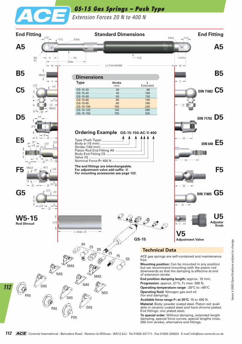
Controls International · Belvedere Road · Newton-le-Willows · WA12 0JJ · Tel 01925 227171 · Fax 01925 229323 · E-mail [email protected]
Technical Data
5
22
28
30
20
22
4,5
∅13 ∅8
12∅ 8
1028
SW13
20
45°M5x0,8
∅8
24° ∅10 ∅6
6
∅5
10
5
6 20
10
5
M5x0,8
5
22
∅10∅ 6,1
10
16 L+/- 2 mm ausgefahren
∅6
∅ 6,1
HubKugelR 5
6 breit
16
6 breit
∅15 10
L = Hub + 20
∅19
22M5x0,8
8
∅13 ∅8
12
10
36°
12
∅13
4,5
10 3012
ACE gas springs are self-contained and maintenance free.Mounting position: Can be mounted in any position but we recommend mounting with the piston rod downwards so that the damping is effective at end of extension stroke.End position damping length: approx. 10 mm.Progression: approx. 27 %, F2 max. 500 N.Operating temperature range: -20°C to +80°C.Operating fluid: Nitrogen gas and oil (for end damping).Available force range F1 at 20°C: 10 to 400 N.Material: Body: powder coated steel. Piston rod: avail-able in ceramic coated steel and hard chrome plated.End fittings: zinc plated steel.To special order: Without damping, extended lengthdamping, special force curves, special lengths (max.250 mm stroke), alternative end fittings.
End Fitting Standard Dimensions End Fitting
Type Stroke Lmm Extended
GS-15-20 20 66GS-15-40 40 106GS-15-50 50 126GS-15-60 60 146GS-15-80 80 186GS-15-100 100 226GS-15-120 120 266GS-15-150 150 326
Dimensions
PA5
OA5
NA5
MA5
NG5
G5
A5C5
D5
F5E5
OG5
PG5
PA5
OA5
NA5
MA5
GS-15
E5
F5
G5
A5
B5
C5
D5
DIN 71802 C5
DIN 71752 D5
DIN 648 E5
F5
DIN 71805 G5
A5
B5
U5Adjuster
Knob
W5-15Rod Shroud
V5 Adjustment Valve
GS-15 Gas Springs – Push TypeExtension Forces 20 N to 400 N
Issu
e 4.
2003
Sp
ecif
icat
ion
s su
bje
ct t
o c
han
ge
112
112
BallR 5
L+/-2 mm extendedStroke
L = Stroke + 20
AF13
6 thick 6 thick
Ordering Example GS-15-150-AC-V-400
Type (Push Type)Body ø (15 mm)Stroke (150 mm)Piston Rod End Fitting A5Body End Fitting C5Valve V5Nominal Force F1 400 N
The end fittings are interchangeable.For adjustment valve add suffix -V. For mounting accessories see page 122.
ACE-Kat_2003_UK_110-115 23.09.2003 9:22 Uhr Seite 112
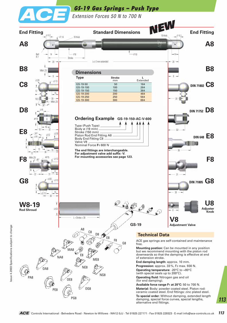
Controls International · Belvedere Road · Newton-le-Willows · WA12 0JJ · Tel 01925 227171 · Fax 01925 229323 · E-mail [email protected]
GS-19 Gas Springs – Push TypeExtension Forces 50 N to 700 N
Issu
e 4.
2003
Sp
ecif
icat
ion
s su
bje
ct t
o c
han
ge
113
113
8
30
31
36
32
30
6
∅20 ∅13
15∅ 13
1231
SW15
22
∅12
24° ∅12 ∅8
8
16
∅16
6
12 3613
∅8
16
8
10 32
16
30M8x1,25
12
∅20 ∅13
15
16,5
36°
9
M8x1,25
8
30
20 L+/- 2 mm ausgefahren 20
L = Hub + 30
∅23
∅ 14∅ 8,1
14 ∅8
∅ 8,1
HubKugelR 7
10 breit 10 breit
∅19 14
45°M8x1,25
Technical Data
ACE gas springs are self-contained and maintenance free.Mounting postion: Can be mounted in any position but we recommend mounting with the piston rod downwards so that the damping is effective at end of extension stroke.End damping length: approx. 10 mm.Progression: approx. 33 %, F2 max. 930 N.Operating temperature: -20°C to +80°C (with special seals up to 200°C).Operating fluid: Nitrogen gas and oil (for end damping).Available force range F1 at 20°C: 50 to 700 N.Material: Body: powder coated steel. Piston rod: ceramic coated steel. End fittings: zinc plated steel.To special order: Without damping, extended length damping, special force curves, special lengths, alternative end fittings.
End Fitting Standard Dimensions End Fitting
Type Stroke Lmm Extended
GS-19-50 50 164GS-19-100 100 264GS-19-150 150 364GS-19-200 200 464GS-19-250 250 564GS-19-300 300 664
Dimensions
PA8
OA8
NA8
MA8
NG8
G8
A8C8
D8
F8E8
OG8
PG8
PE8
OE8
NE8
ME8E8
GS-19
E8
F8
G8
A8
B8
C8
D8
DIN 71802 C8
DIN 71752 D8
DIN 648 E8
F8
DIN 71805 G8
A8
B8
U8Adjuster
Knob
W8-19Rod Shroud
V8 Adjustment Valve
AF15
BallR 7
L+/-2 mm extendedStroke
L = Stroke + 30
10 thick 10 thickNEW
Ordering Example GS-19-150-AC-V-600
Type (Push Type)Body ø (19 mm)Stroke (150 mm)Piston Rod End Fitting A8Body End Fitting C8Valve V8Nominal Force F1 600 N
The end fittings are interchangeable.For adjustment valve add suffix -V. For mounting accessories see page 123.
ACE-Kat_2003_UK_110-115 23.09.2003 9:23 Uhr Seite 113
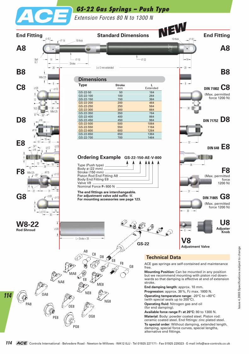
Controls International · Belvedere Road · Newton-le-Willows · WA12 0JJ · Tel 01925 227171 · Fax 01925 229323 · E-mail [email protected]
8
30
31
36
32
30
6
∅20 ∅13
15∅ 13
1231
SW15
22
∅12
24° ∅12 ∅8
8
16
∅16
6
12 3613
∅8
16
8
10 32
16
30M8x1,25
12
∅20 ∅13
15
16,5
36°
9
M8x1,25
8
30
∅ 14∅ 8,1
14
20 L+/- 2 mm ausgefahren
∅ 10
∅ 8,1
HubKugelR 7
10 breit
20
10 breit
∅ 22 14
L = Hub + 30
∅28
45°M8x1,25
ACE gas springs are self-contained and maintenance free.Mounting Position: Can be mounted in any position but we recommend mounting with piston rod down-wards so that damping is effective at end of extensionstroke.End damping length: approx. 10 mm.Progression: approx. 38 %, F2 max. 1800 N.Operating temperature range: -20°C to +80°C (with special seals up to 200°C).Operating fluid: Nitrogen gas and oil (for end damping).Available force range F1 at 20°C: 80 to 1300 N.Material: Body: powder coated steel. Piston rod: ceramic coated steel. End fittings: zinc plated steel.To special order: Without damping, extended length, damping, special force curves, special lengths, alternative end fittings.
Technical Data
Type Stroke Lmm Extended
GS-22-50 50 164GS-22-100 100 264GS-22-150 150 364GS-22-200 200 464GS-22-250 250 564GS-22-300 300 664GS-22-350 350 764GS-22-400 400 864GS-22-450 450 964GS-22-500 500 1064GS-22-550 550 1164GS-22-600 600 1264GS-22-650 650 1364GS-22-700 700 1464
Dimensions
PA8
OA8
NA8
MA8
NG8
G8
A8C8
D8
F8E8
OG8
PG8
PE8
OE8
NE8
ME8E8
GS-22
E8
F8
G8
A8
B8
C8
D8
End Fitting Standard Dimensions End Fitting
DIN 71802 C8
DIN 71752 D8
DIN 648 E8
F8
DIN 71805 G8
A8
B8
V8 Adjustment Valve
U8Adjuster
Knob
W8-22Rod Shroud
(Max. permitted force 1200 N)
(Max. permitted force
1200 N)
(Max. permitted force 1200 N)
GS-22 Gas Springs – Push TypeExtension Forces 80 N to 1300 N
Issu
e 4.
2003
Sp
ecif
icat
ion
s su
bje
ct t
o c
han
ge
114
114
AF15
BallR 7
L+/-2 mm extendedStroke
L = Stroke + 30
10 thick 10 thickNEW
Ordering Example GS-22-150-AE-V-800
Type (Push type)Body ø (22 mm)Stroke (150 mm)Piston Rod End Fitting A8Body End Fitting E8Valve V8Nominal Force F1 800 N
The end fittings are interchangeable.For adjustment valve add suffix -V. For mounting accessories see page 123.
ACE-Kat_2003_UK_110-115 23.09.2003 9:23 Uhr Seite 114
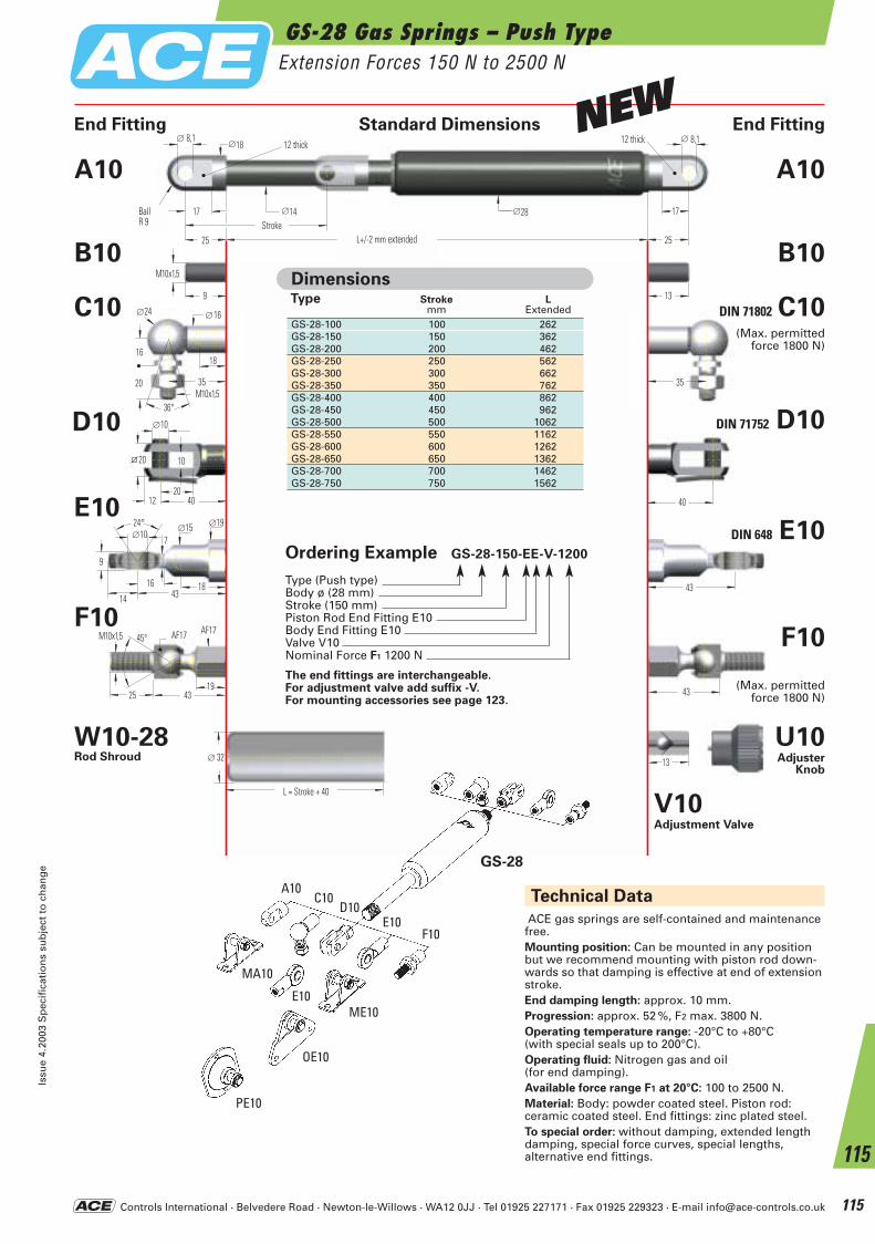
Controls International · Belvedere Road · Newton-le-Willows · WA12 0JJ · Tel 01925 227171 · Fax 01925 229323 · E-mail [email protected]
GS-28 Gas Springs – Push TypeExtension Forces 150 N to 2500 N
Issu
e 4.
2003
Sp
ecif
icat
ion
s su
bje
ct t
o c
han
ge
115
115
43
24° ∅15 ∅10
9
18
∅19
7
14 4316
431943
SW17
25
SW17
40
∅10
20
10
12 40
20
35M10x1,5
16
∅24 ∅16
18
20
36°
9
M10x1,5
13
35
25 L+/- 2 mm ausgefahren 25
∅18∅ 8,1
17 ∅14
∅ 8,1
HubKugelR 9
12 breit 12 breit
∅28 17
13
L = Hub + 40
∅ 32
45°M10x1,5
Technical Data
ACE gas springs are self-contained and maintenance free.Mounting position: Can be mounted in any position but we recommend mounting with piston rod down-wards so that damping is effective at end of extensionstroke.End damping length: approx. 10 mm.Progression: approx. 52 %, F2 max. 3800 N.Operating temperature range: -20°C to +80°C (with special seals up to 200°C).Operating fluid: Nitrogen gas and oil (for end damping).Available force range F1 at 20°C: 100 to 2500 N.Material: Body: powder coated steel. Piston rod: ceramic coated steel. End fittings: zinc plated steel.To special order: without damping, extended length damping, special force curves, special lengths, alternative end fittings.
Type Stroke Lmm Extended
GS-28-100 100 262GS-28-150 150 362GS-28-200 200 462GS-28-250 250 562GS-28-300 300 662GS-28-350 350 762GS-28-400 400 862GS-28-450 450 962GS-28-500 500 1062GS-28-550 550 1162GS-28-600 600 1262GS-28-650 650 1362GS-28-700 700 1462GS-28-750 750 1562
Dimensions
End Fitting Standard Dimensions End Fitting
GS-28
MA10
OE10
F10
A10C10
D10E10
PE10
ME10E10
V10 Adjustment Valve
E10
F10
A10
B10
C10
D10
DIN 71802 C10
DIN 71752 D10
DIN 648 E10
F10
A10
B10
U10Adjuster
Knob
W10-28Rod Shroud
(Max. permitted force 1800 N)
(Max. permitted force 1800 N)
AF17 AF17
BallR 9
L+/-2 mm extendedStroke
L = Stroke + 40
12 thick 12 thickNEW
Ordering Example GS-28-150-EE-V-1200
Type (Push type)Body ø (28 mm)Stroke (150 mm)Piston Rod End Fitting E10Body End Fitting E10Valve V10Nominal Force F1 1200 N
The end fittings are interchangeable.For adjustment valve add suffix -V. For mounting accessories see page 123.
ACE-Kat_2003_UK_110-115 23.09.2003 9:23 Uhr Seite 115
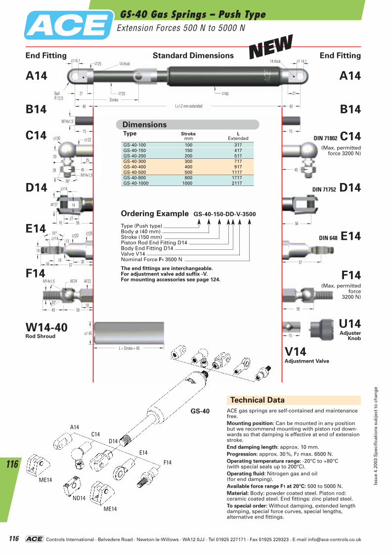
Controls International · Belvedere Road · Newton-le-Willows · WA12 0JJ · Tel 01925 227171 · Fax 01925 229323 · E-mail [email protected]
GS-40 Gas Springs – Push TypeExtension Forces 500 N to 5000 N
Issu
e 4.
2003
Sp
ecif
icat
ion
s su
bje
ct t
o c
han
ge
116
116
5618
56
SW24
40
30°
M14x1,5 SW22
57
16° ∅20 ∅14
19
30
∅26
13
5718
56
∅14
27
14
16 56
27
45M14x1,5
20
∅30 ∅22
25
28
36°
15
M14x1,5
15
45
40 L+/- 2 mm ausgefahren 40
∅25∅ 14,1
21 ∅20
∅14,1
HubKugelR 12,5
14 breit 14 breit
∅40 21
15
L = Hub + 40
∅ 45
18
ACE gas springs are self-contained and maintenance free.Mounting position: Can be mounted in any position but we recommend mounting with piston rod down-wards so that damping is effective at end of extensionstroke.End damping length: approx. 10 mm.Progression: approx. 30 %, F2 max. 6500 N.Operating temperature range: -20°C to +80°C(with special seals up to 200°C).Operating fluid: Nitrogen gas and oil (for end damping).Available force range F1 at 20°C: 500 to 5000 N.Material: Body: powder coated steel. Piston rod: ceramic coated steel. End fittings: zinc plated steel.To special order: Without damping, extended length damping, special force curves, special lengths, alternative end fittings.
Technical Data
Type Stroke Lmm Extended
GS-40-100 100 317GS-40-150 150 417GS-40-200 200 517GS-40-300 300 717GS-40-400 400 917GS-40-500 500 1117GS-40-800 800 1717GS-40-1000 1000 2117
Dimensions
End Fitting Standard Dimensions End Fitting
ME14
A14C14
D14
F14
E14
ND14
GS-40
E14
F14
A14
B14
C14
D14
DIN 71802 C14
DIN 71752 D14
DIN 648 E14
F14
A14
B14
V14Adjustment Valve
U14Adjuster
Knob
W14-40Rod Shroud
ME14
(Max. permitted force 3200 N)
(Max. permitted force
3200 N)
AF24 AF22
BallR 12,5
L+/-2 mm extendedStroke
L = Stroke + 40
14 thick 14 thickNEW
Ordering Example GS-40-150-DD-V-3500
Type (Push type)Body ø (40 mm)Stroke (150 mm)Piston Rod End Fitting D14Body End Fitting D14Valve V14Nominal Force F1 3500 N
The end fittings are interchangeable.For adjustment valve add suffix -V. For mounting accessories see page 124.
ACE-Kat_2003_UK_116-121 23.09.2003 9:28 Uhr Seite 116
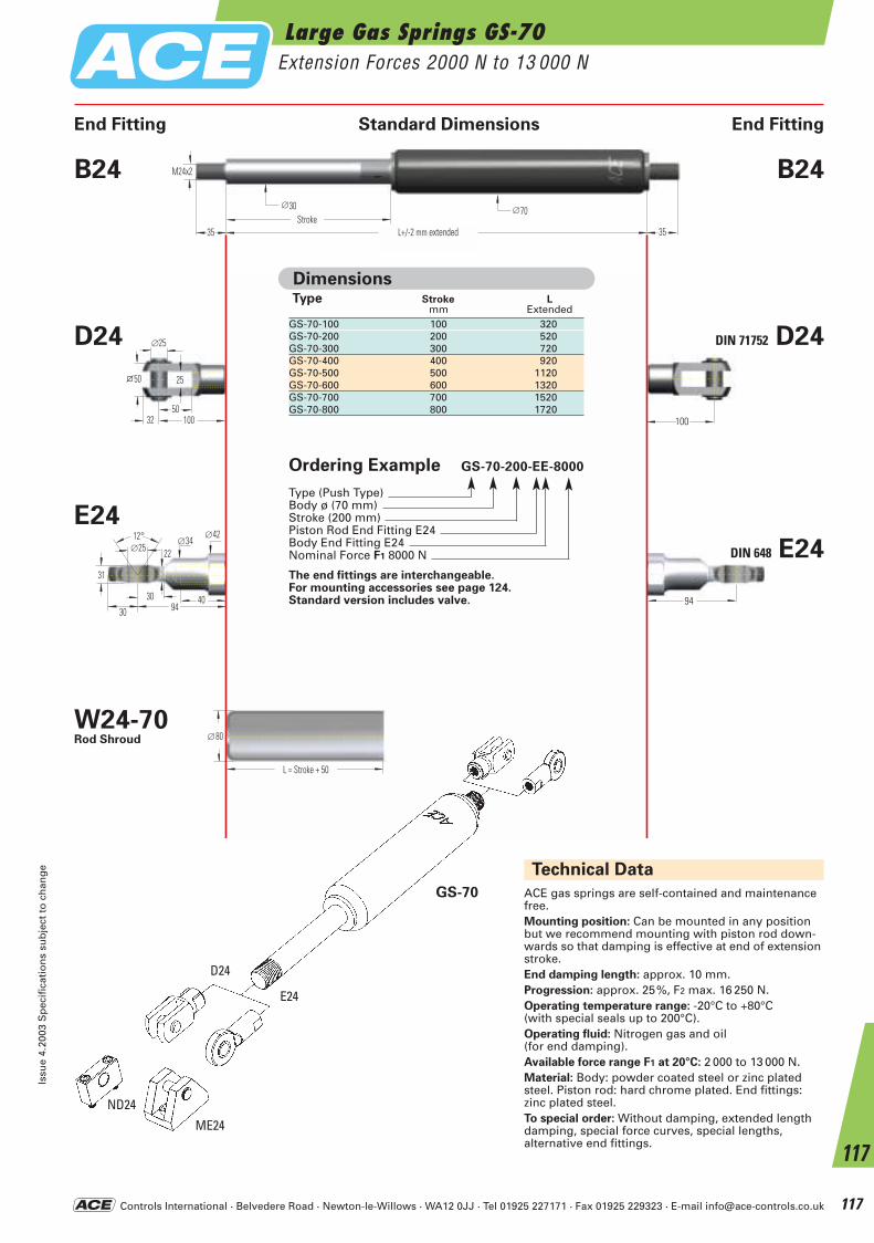
Controls International · Belvedere Road · Newton-le-Willows · WA12 0JJ · Tel 01925 227171 · Fax 01925 229323 · E-mail [email protected]
Large Gas Springs GS-70Extension Forces 2000 N to 13 000 N
Issu
e 4.
2003
Sp
ecif
icat
ion
s su
bje
ct t
o c
han
ge
117
117
100
∅25
50
25
32 100
50
94
12° ∅34 ∅25
31
∅42
40
22
30 9430
35 L+/- 2 mm ausgefahren
∅30Hub
∅70
M24x2
35
L = Hub + 50
∅80
ACE gas springs are self-contained and maintenance free.Mounting position: Can be mounted in any position but we recommend mounting with piston rod down-wards so that damping is effective at end of extensionstroke.End damping length: approx. 10 mm.Progression: approx. 25%, F2 max. 16 250 N.Operating temperature range: -20°C to +80°C(with special seals up to 200°C).Operating fluid: Nitrogen gas and oil (for end damping).Available force range F1 at 20°C: 2 000 to 13 000 N.Material: Body: powder coated steel or zinc platedsteel. Piston rod: hard chrome plated. End fittings:zinc plated steel.To special order: Without damping, extended length damping, special force curves, special lengths, alternative end fittings.
Technical Data
Type Stroke Lmm Extended
GS-70-100 100 320GS-70-200 200 520GS-70-300 300 720GS-70-400 400 920GS-70-500 500 1120GS-70-600 600 1320GS-70-700 700 1520GS-70-800 800 1720
Dimensions
End Fitting Standard Dimensions End Fitting
ME24
D24
E24
ND24
GS-70
E24
B24
D24 DIN 71752 D24
DIN 648 E24
B24
W24-70Rod Shroud
Ordering Example GS-70-200-EE-8000
Type (Push Type)Body ø (70 mm)Stroke (200 mm)Piston Rod End Fitting E24 Body End Fitting E24 Nominal Force F1 8000 N
The end fittings are interchangeable.For mounting accessories see page 124.Standard version includes valve.
L+/-2 mm extendedStroke
L = Stroke + 50
ACE-Kat_2003_UK_116-121 23.09.2003 9:28 Uhr Seite 117
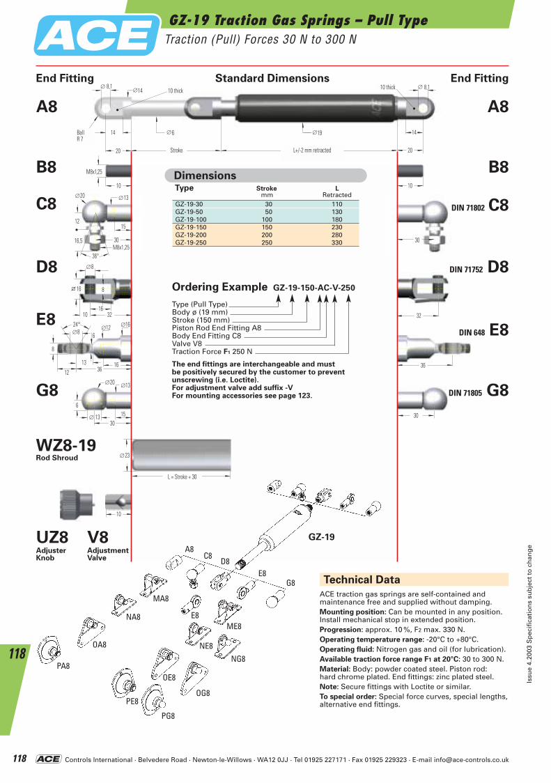
Controls International · Belvedere Road · Newton-le-Willows · WA12 0JJ · Tel 01925 227171 · Fax 01925 229323 · E-mail [email protected]
10
30
36
32
30
6
∅20 ∅13
15∅ 13
24° ∅12 ∅8
8
16
∅16
6
12 3613
∅8
16
8
10 32
16
30M8x1,25
12
∅20 ∅13
15
16,5
36°
10
M8x1,25
10
30
20 L+/- 2 mm eingefahren 20
∅14∅ 8,1
14 ∅6
∅ 8,1
Hub
KugelR 7
10 breit 10 breit
∅19 14
L = Hub + 30
∅23
Technical Data
ACE traction gas springs are self-contained and maintenance free and supplied without damping.Mounting position: Can be mounted in any position.Install mechanical stop in extended position.Progression: approx. 10 %, F2 max. 330 N.Operating temperature range: -20°C to +80°C.Operating fluid: Nitrogen gas and oil (for lubrication).Available traction force range F1 at 20°C: 30 to 300 N.Material: Body: powder coated steel. Piston rod:hard chrome plated. End fittings: zinc plated steel.Note: Secure fittings with Loctite or similar.To special order: Special force curves, special lengths, alternative end fittings.
Type Stroke Lmm Retracted
GZ-19-30 30 110GZ-19-50 50 130GZ-19-100 100 180GZ-19-150 150 230GZ-19-200 200 280GZ-19-250 250 330
Dimensions
End Fitting Standard Dimensions End Fitting
E8
G8
A8
B8
C8
D8
DIN 71802 C8
DIN 71752 D8
DIN 648 E8
DIN 71805 G8
A8
B8
UZ8AdjusterKnob
GZ-19V8AdjustmentValve
WZ8-19Rod Shroud
PA8
OA8
NA8
MA8
NG8
G8
A8C8
D8E8
OG8
PG8
PE8
OE8
NE8
ME8E8
GZ-19 Traction Gas Springs – Pull TypeTraction (Pull) Forces 30 N to 300 N
Issu
e 4.
2003
Sp
ecif
icat
ion
s su
bje
ct t
o c
han
ge
118
118
BallR 7
L+/-2 mm retractedStroke
L = Stroke + 30
10 thick 10 thick
Ordering Example GZ-19-150-AC-V-250
Type (Pull Type)Body ø (19 mm)Stroke (150 mm)Piston Rod End Fitting A8 Body End Fitting C8Valve V8Traction Force F1 250 N
The end fittings are interchangeable and must be positively secured by the customer to prevent unscrewing (i.e. Loctite).For adjustment valve add suffix -VFor mounting accessories see page 123.
ACE-Kat_2003_UK_116-121 23.09.2003 9:29 Uhr Seite 118
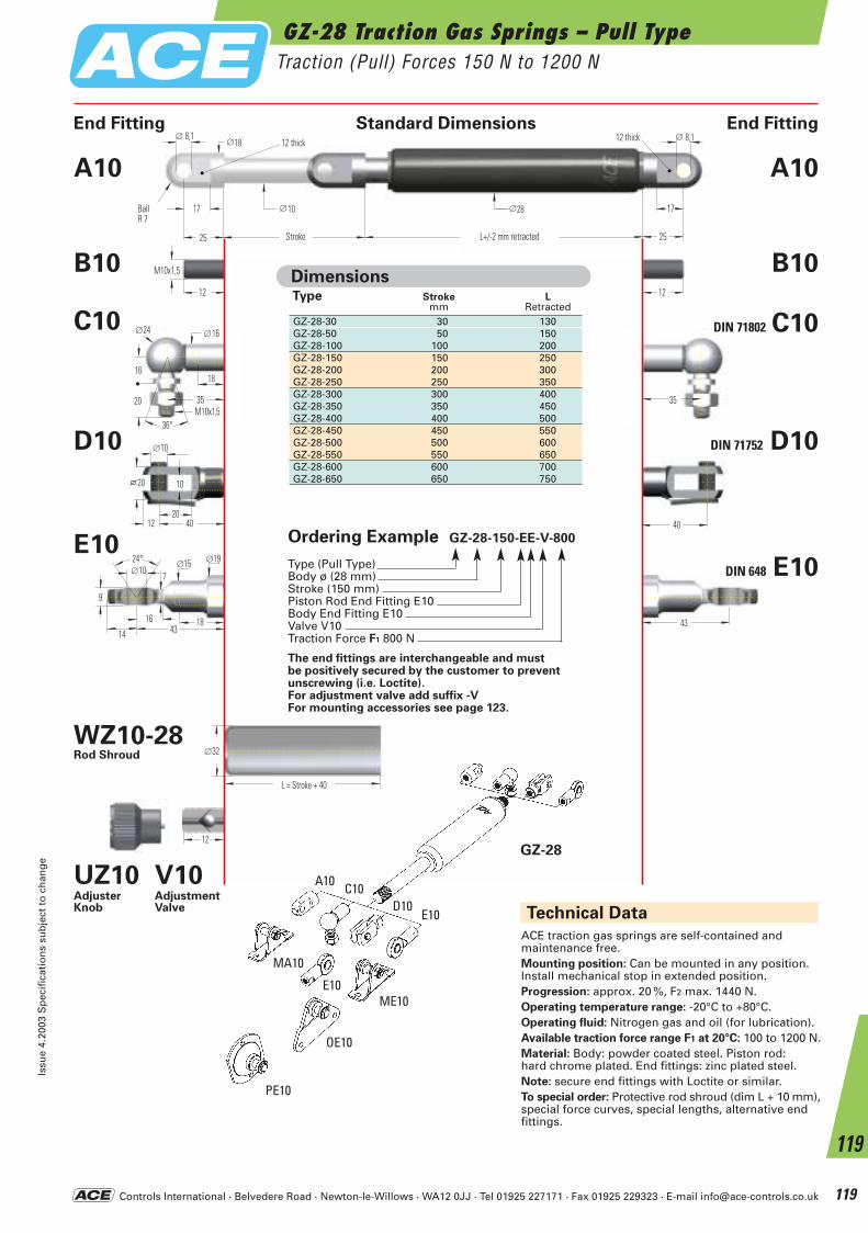
Controls International · Belvedere Road · Newton-le-Willows · WA12 0JJ · Tel 01925 227171 · Fax 01925 229323 · E-mail [email protected]
GZ-28 Traction Gas Springs – Pull TypeTraction (Pull) Forces 150 N to 1200 N
Issu
e 4.
2003
Sp
ecif
icat
ion
s su
bje
ct t
o c
han
ge
119
119
Technical Data
ACE traction gas springs are self-contained and maintenance free.Mounting position: Can be mounted in any position. Install mechanical stop in extended position.Progression: approx. 20 %, F2 max. 1440 N.Operating temperature range: -20°C to +80°C.Operating fluid: Nitrogen gas and oil (for lubrication).Available traction force range F1 at 20°C: 100 to 1200 N.Material: Body: powder coated steel. Piston rod: hard chrome plated. End fittings: zinc plated steel.Note: secure end fittings with Loctite or similar.To special order: Protective rod shroud (dim L + 10 mm),special force curves, special lengths, alternative end fittings.
12
43
24° ∅15 ∅10
9
18
∅19
7
14 4316
40
∅10
20
10
12 40
20
12
M10x1,5
12
25
∅18∅ 8,1
17 ∅10
∅ 8,1
KugelR 9
12 breit 12 breit
∅28 17
L+/- 2 mm eingefahren 25
35M10x1,5
16
∅24 ∅16
18
20
36°
35
L = Hub + 40
∅32
Hub
Type Stroke Lmm Retracted
GZ-28-30 30 130GZ-28-50 50 150GZ-28-100 100 200GZ-28-150 150 250GZ-28-200 200 300GZ-28-250 250 350GZ-28-300 300 400GZ-28-350 350 450GZ-28-400 400 500GZ-28-450 450 550GZ-28-500 500 600GZ-28-550 550 650GZ-28-600 600 700GZ-28-650 650 750
Dimensions
End Fitting Standard Dimensions End Fitting
MA10
A10 C10D10
E10
OE10
PE10
ME10E10
E10
A10
B10
C10
D10
DIN 71802 C10
DIN 71752 D10
DIN 648 E10
A10
B10
GZ-28
UZ10AdjusterKnob
V10AdjustmentValve
WZ10-28Rod Shroud
BallR 7
L+/-2 mm retractedStroke
L = Stroke + 40
12 thick 12 thick
Ordering Example GZ-28-150-EE-V-800
Type (Pull Type)Body ø (28 mm)Stroke (150 mm)Piston Rod End Fitting E10 Body End Fitting E10Valve V10Traction Force F1 800 N
The end fittings are interchangeable and must be positively secured by the customer to prevent unscrewing (i.e. Loctite).For adjustment valve add suffix -VFor mounting accessories see page 123.
ACE-Kat_2003_UK_116-121 23.09.2003 9:29 Uhr Seite 119
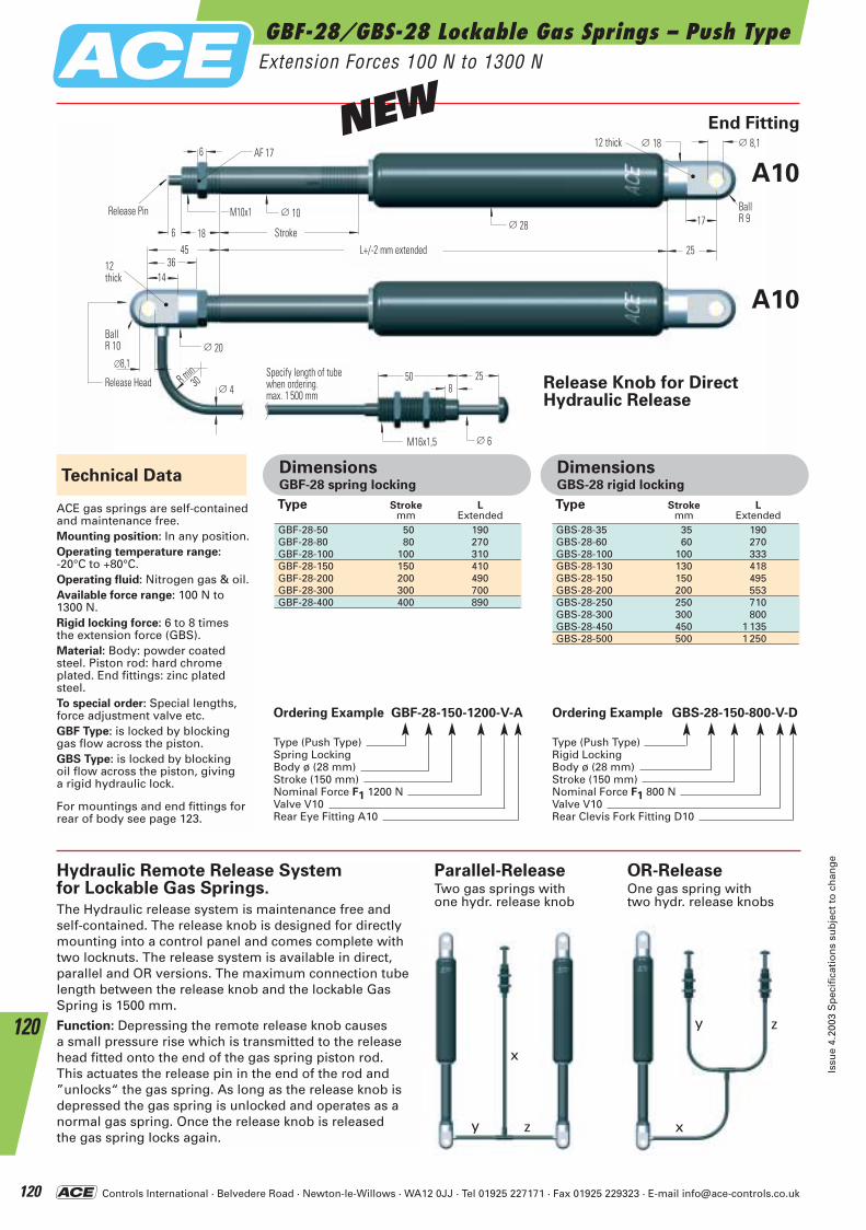
Controls International · Belvedere Road · Newton-le-Willows · WA12 0JJ · Tel 01925 227171 · Fax 01925 229323 · E-mail [email protected]
GBF-28/GBS-28 Lockable Gas Springs – Push TypeExtension Forces 100 N to 1300 N
Issu
e 4.
2003
Sp
ecif
icat
ion
s su
bje
ct t
o c
han
ge
120
120
∅ 20
∅ 8,1
18
14
L+/- 2 mm ausgefahren
∅ 10
Hub
KugelR 10
25
12 breit
∅ 28 17M10x1
6
6 SW 17
3645
12breit
∅8,1R min
30
∅ 4Schlauchlänge beiBestellung angeben,max. 1500 mm
M16x1,5 ∅ 6
508
25
∅ 18
KugelR9
Auslösekopf
Auslösestift
Ordering Example GBF-28-150-1200-V-A
Type (Push Type)Spring LockingBody ø (28 mm)Stroke (150 mm)Nominal Force F1 1200 NValve V10Rear Eye Fitting A10
Technical Data
Release Knob for Direct Hydraulic Release
Parallel-ReleaseTwo gas springs withone hydr. release knob
OR-ReleaseOne gas spring withtwo hydr. release knobs
ACE gas springs are self-contained and maintenance free.Mounting position: In any position.Operating temperature range:-20°C to +80°C.Operating fluid: Nitrogen gas & oil.Available force range: 100 N to1300 N.Rigid locking force: 6 to 8 times the extension force (GBS).Material: Body: powder coatedsteel. Piston rod: hard chrome plated. End fittings: zinc platedsteel.To special order: Special lengths, force adjustment valve etc. GBF Type: is locked by blocking gas flow across the piston.GBS Type: is locked by blocking oil flow across the piston, giving a rigid hydraulic lock.
For mountings and end fittings forrear of body see page 123.
Ordering Example GBS-28-150-800-V-D
Type (Push Type)Rigid LockingBody ø (28 mm)Stroke (150 mm)Nominal Force F1 800 NValve V10Rear Clevis Fork Fitting D10
Hydraulic Remote Release Systemfor Lockable Gas Springs.
The Hydraulic release system is maintenance free and self-contained. The release knob is designed for directlymounting into a control panel and comes complete with two locknuts. The release system is available in direct, parallel and OR versions. The maximum connection tube length between the release knob and the lockable Gas Spring is 1500 mm.
Function: Depressing the remote release knob causes a small pressure rise which is transmitted to the release head fitted onto the end of the gas spring piston rod. This actuates the release pin in the end of the rod and ”unlocks“ the gas spring. As long as the release knob is depressed the gas spring is unlocked and operates as a normal gas spring. Once the release knob is released the gas spring locks again.
Type Stroke L mm Extended
GBF-28-50 50 190GBF-28-80 80 270GBF-28-100 100 310GBF-28-150 150 410GBF-28-200 200 490GBF-28-300 300 700GBF-28-400 400 890
DimensionsGBF-28 spring locking
Type Stroke L mm Extended
GBS-28-35 35 190GBS-28-60 60 270GBS-28-100 100 333GBS-28-130 130 418GBS-28-150 150 495GBS-28-200 200 553GBS-28-250 250 710GBS-28-300 300 800GBS-28-450 450 1 135GBS-28-500 500 1 250
DimensionsGBS-28 rigid locking
x
y z x
y z
End Fitting
A10
A10
AF 17
Release Pin
Stroke
12thick
12 thick
BallR 10
BallR 9
Release HeadSpecify length of tubewhen ordering.max. 1 500 mm
L+/-2 mm extended
NEW
ACE-Kat_2003_UK_116-121 23.09.2003 9:29 Uhr Seite 120
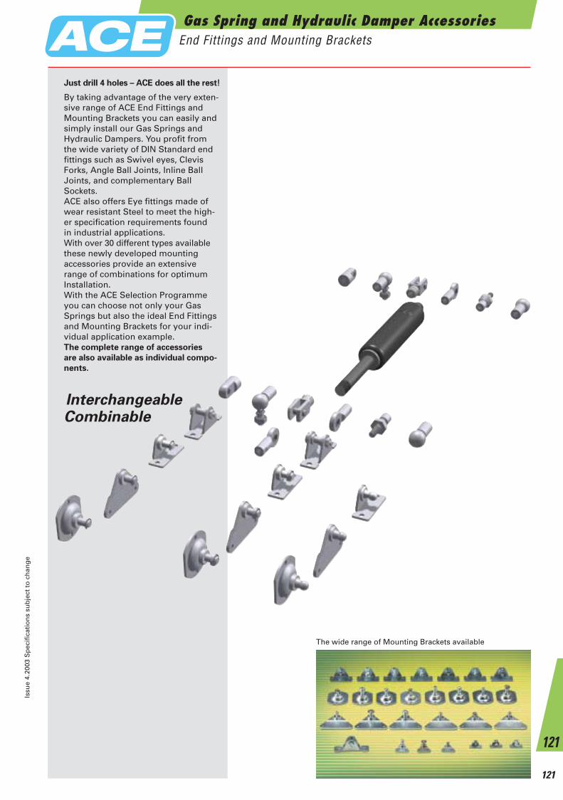
Just drill 4 holes – ACE does all the rest!
By taking advantage of the very exten-sive range of ACE End Fittings andMounting Brackets you can easily andsimply install our Gas Springs andHydraulic Dampers. You profit from the wide variety of DIN Standard end fittings such as Swivel eyes, ClevisForks, Angle Ball Joints, Inline BallJoints, and complementary BallSockets.ACE also offers Eye fittings made of wear resistant Steel to meet the high-er specification requirements found in industrial applications.With over 30 different types available these newly developed mounting accessories provide an extensive range of combinations for optimum Installation.With the ACE Selection Programme you can choose not only your Gas Springs but also the ideal End Fittings and Mounting Brackets for your indi-vidual application example.The complete range of accessories
are also available as individual compo-
nents.
The wide range of Mounting Brackets available
InterchangeableCombinable
Gas Spring and Hydraulic Damper AccessoriesEnd Fittings and Mounting Brackets
Issu
e 4.
2003
Sp
ecif
icat
ion
s su
bje
ct t
o c
han
ge
121
121
ACE-Kat_2003_UK_116-121 23.09.2003 9:31 Uhr Seite 121
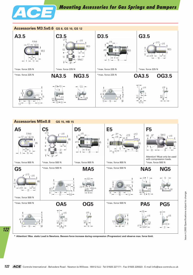
Controls International · Belvedere Road · Newton-le-Willows · WA12 0JJ · Tel 01925 227171 · Fax 01925 229323 · E-mail [email protected]
Mounting Accessories for Gas Springs and Dampers
Issu
e 4.
2003
Sp
ecif
icat
ion
s su
bje
ct t
o c
han
ge
122
122
Accessories M3.5x0.6
4 ∅
8
4
5 16
M3,58
18M4x0,7
8,5
∅13 ∅8
6
10
36°
M3,5
18
4
∅13 ∅8
6
M3,5
∅ 88
12
4,14 breit
M3,5
64
∅8
G3.5 C3.5 D3.5 A3.5
GS 8, GS 10, GS 12
Accessories M5x0.8 GS 15, HB 15
NG3.5 NA3.5 OG3.5 OA3.5
∅8
163191,5
∅3,3
4
10 ∅4
3,5 4,5
5,5 4,50,5 ∅8
12,5
4,5
185
4,3
5
16
∅8
13
5
∅41
21,5
4,5 4,5
∅8
5,5
14
*max. force 225 N *max. force 225 N *max. force 225 N *max. force 225 N
*max. force 225 N *max. force 225 N
∅5
10
5
6 20
M510
22M5
8
∅13 ∅8
12
10
36°
M5
10
16
6,16 breit
M5
85
∅10
F5C5 D5 E5 A5
MA5 NG5NA5
369,551
2,5∅6,413
20
9
∅6
6,5
18
2,54
34540
2∅5,5
10
16
14
OG5OA5 PG5PA5
185
4,3
5
16
10
13
5
∅61
2,51,5
6 6,5 44
555,5
41
∅6
10
2,5
14 7∅14
∅8
218
2
24° ∅10 ∅6
6
12
∅13
4,5
10 3012
M5
1028
SW13
20
45°M5 ∅8
M5
*max. force 800 N
*max. force 500 N
*max. force 500 N *max. force 800 N *max. force 800 N *max. force 500 N
*max. force 500 N *max. force 500 N
∅8
5,5
14
22
4,5
∅13 ∅8
12
M5
∅ 8
G5
∅6
6 7
10 101,3 ∅8
13
5
* Attention! Max. static Load in Newtons. Beware force increase during compression (Progression) and observe max. force limit.
*max. force 500 N *max. force 500 N
Attention! Must only be usedwith compression loads.
6 thick
4 thick
SW13
ACE-Kat_2003_UK_122-127 23.09.2003 9:34 Uhr Seite 122
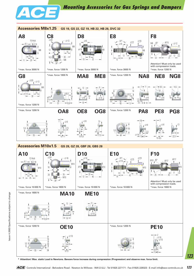
Controls International · Belvedere Road · Newton-le-Willows · WA12 0JJ · Tel 01925 227171 · Fax 01925 229323 · E-mail [email protected]
Mounting Accessories for Gas Springs and DampersIs
sue
4.20
03 S
pec
ific
atio
ns
sub
ject
to
ch
ang
e
123
123
30
6
∅20 ∅13
15
M8
∅ 13
Accessories M10x1.5 GS 28, GZ 28, GBF 28, GBS 28
ME10MA10
369,551
2,5∅6,413
20
9
18
∅8
13
4
OE10 PE10
557
5,5
10
30
16
23
7
∅10
43
10 9
2
44
555,5
41∅10
2
4
15 9
∅16
10
*max. force 1800 N
*max. force 1200 N
Accessories M8x1.25 GS 19, GS 22, GZ 19, HB 22, HB 28, DVC 32
∅8
16
8
10 32
M816
30M8
12
∅20 ∅13
15
16,5
36°
M8
14
20
8,110 breit
M8
106
∅14
F8C8 D8 E8 A8
ME8MA8 NE8 NG8NA8
369,551
2,5∅6,413
20
9
18
∅8
13
434
540
2∅5,5
10
16
16
OE8 OG8OA8 PG8PA8 PE8
557
5,5
10
30
16
23
7
∅82
2,53
10 11
∅8
53
10 8,5 44
555,5
41∅8
10
2,5
15 11∅16
13
22,59
∅8
2
5
15 8,5
24° ∅12 ∅8
8
16
∅16
6
12 3613
M8
1231
SW15
22
45°M8 ∅12
M8
*max. force 3000 N
*max. force 1200 N
*max. force 1200 N *max. force 3000 N *max. force 3000 N *max. force 1200 N
∅10
20
10
12 40
M1020
35M10
16
∅24 ∅16
18
20
36°
M10
17
25
8,112 breit
M10
159
∅18
F10C10 D10 E10 A10 24° ∅15
∅10
9
18
∅19
7
14 4316
M10
1743
SW17
25
45°M10 SW17
M10
*max. force 10 000 N *max. force 1800 N *max. force 10 000 N *max. force 10 000 N *max. force 1800 N
*max. force 1800 N *max. force 1200 N
13
8
17,5
∅ 8
8
G8
∅8
7 11
10 101,3
∅8
7 8,5
13
14,5
5
∅10
9
* Attention! Max. static Load in Newtons. Beware force increase during compression (Progression) and observe max. force limit.
*max. force 1200 N *max. force 1200 N
*max. force 1200 N
Attention! Must only be usedwith compression loads.
Attention! Must only be usedwith compression loads.
10 thick
12 thick
AF15
AF17AF17
ACE-Kat_2003_UK_122-127 23.09.2003 9:34 Uhr Seite 123
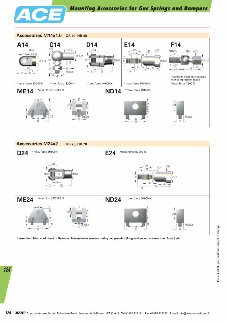
Controls International · Belvedere Road · Newton-le-Willows · WA12 0JJ · Tel 01925 227171 · Fax 01925 229323 · E-mail [email protected]
1856
SW24
40
30°
M14x1,5
M14x1,5
SW22
Mounting Accessories for Gas Springs and Dampers
Issu
e 4.
2003
Sp
ecif
icat
ion
s su
bje
ct t
o c
han
ge
124
124
16° ∅20 ∅14
19
30
∅26
13
18 5718
M14x1,5
∅14
27
14
16 56
M14x1,527
45M14x1,5
20
∅30 ∅22
25
28
36°
M14x1,5
Accessories M14x1.5 GS 40, HB 40
Accessories M24x2 GS 70, HB 70
ME14 ND14*max. force 10 000 N *max. force 10 000 N
21
40
14,114 breit
M14x1,5
1812
∅25
F14C14 D14 E14 A14
*max. force 10 000 N *max. force 3200 N *max. force 10 000 N *max. force 10 000 N *max. force 3200 N
ME24 ND24
80
40
56
20
12
*max. force 50 000 N *max. force 50 000 N
∅25
50
25
32 100
M24x250
E24D24
12° ∅34 ∅25
31
40
∅42
22
30 9430
M24x2
*max. force 50 000 N *max. force 50 000 N
* Attention! Max. static Load in Newtons. Beware force increase during compression (Progression) and observe max. force limit.
Attention! Must only be usedwith compression loads.
14 thick AF24 AF22
10
4660
28
1226
640
20
∅14
M8x1,25
20
50
20
36
12
6 M8x1,2514
∅14
20
7090
45
2040
1060
32
∅25
M12x1,75
33
M12x1,7524
∅25
ACE-Kat_2003_UK_122-127 23.09.2003 9:35 Uhr Seite 124
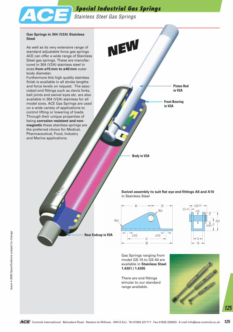
Controls International · Belvedere Road · Newton-le-Willows · WA12 0JJ · Tel 01925 227171 · Fax 01925 229323 · E-mail [email protected]
40
∅6,5
25,8R4,5
29
R8,5
69
∅6,551
17∅8,5
1813
∅8
23,6 +0,5
2,5
Swivel assembly to suit flat eye end fittings A8 and A10
in Stainless Steel
Special Industrial Gas SpringsStainless Steel Gas Springs
Issu
e 4.
2003
Sp
ecif
icat
ion
s su
bje
ct t
o c
han
ge
125
125
Gas Springs in 304 (V2A) Stainless
Steel
As well as its very extensive range ofstandard adjustable force gas springsACE can offer a wide range of StainlessSteel gas springs. These are manufac-tured in 304 (V2A) stainless steel in sizes from ø15 mm to ø40 mm outerbody diameter. Furthermore this high quality stainlessfinish is available in all stroke lengthsand force levels on request. The asso-ciated end fittings such as clevis forks,ball joints and swivel eyes etc. are alsoavailable in 304 (V2A) stainless for allmodel sizes. ACE Gas Springs are usedon a wide variety of applications tocontrol lifting or lowering of loads.Through their unique properties ofbeing corrosion resistant and non-
magnetic these stainless springs arethe preferred choice for Medical,Pharmaceutical, Food, Industry and Marine applications.
Piston Rod in V2A
Front Bearing in V2A
Body in V2A
Rear Endcap in V2A
Gas Springs ranging frommodel GS-15 to GS-40 areavailable in Stainless Steel
1.4301 / 1.4305
There are end fittings simular to our standard range available.
NEW
ACE-Kat_2003_UK_122-127 23.09.2003 9:35 Uhr Seite 125
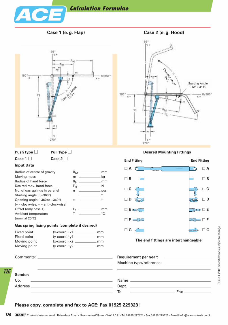
Controls International · Belvedere Road · Newton-le-Willows · WA12 0JJ · Tel 01925 227171 · Fax 01925 229323 · E-mail [email protected]
Calculation Formulae
Issu
e 4.
2003
Sp
ecif
icat
ion
s su
bje
ct t
o c
han
ge
126
126
Desired Mounting Fittings
A A
B B
C C
D D
E E
F F
G G
The end fittings are interchangeable.
Gas spring fixing points (complete if desired)
Fixed point (x-coord.) x1 mmFixed point (y-coord.) y1 mmMoving point (x-coord.) x2 mmMoving point (y-coord.) y2 mm
Comments:
Sender:
Co.Address
NameDept.Tel Fax
Requirement per year:
Machine type/reference:
Please copy, complete and fax to ACE: Fax 01925 229323!
Case 1 (e. g. Flap) Case 2 (e. g. Hood)
Openin
g Angle
(-90°)
Starting Angle(-12° = 348°)
Opening Angle
(80°)
Push type Pull type
Case 1 Case 2
Input Data
Radius of centre of gravity RM mmMoving mass m kgRadius of hand force RH mmDesired max. hand force FH NNo. of gas springs in parallel n pcsStarting angle (0 – 360°) °Opening angle (–360 to +360°) a °(– = clockwise, + = anti-clockwise)Offset (only case 1) L1 mmAmbient temperature T °C(normal 20°C)
End Fitting End Fitting
ACE-Kat_2003_UK_122-127 23.09.2003 9:35 Uhr Seite 126
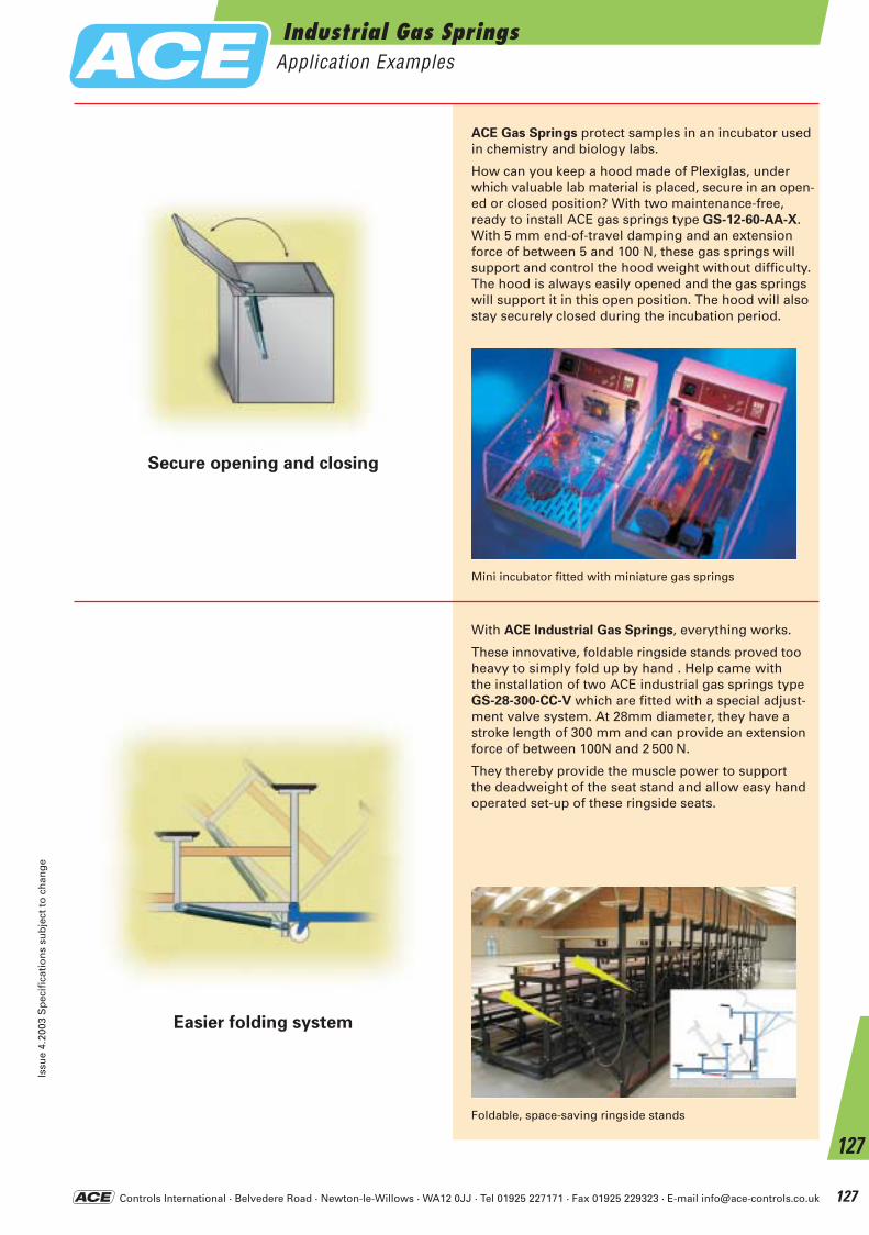
Controls International · Belvedere Road · Newton-le-Willows · WA12 0JJ · Tel 01925 227171 · Fax 01925 229323 · E-mail [email protected]
Easier folding system
Secure opening and closing
ACE Gas Springs protect samples in an incubator usedin chemistry and biology labs.
How can you keep a hood made of Plexiglas, underwhich valuable lab material is placed, secure in an open-ed or closed position? With two maintenance-free, ready to install ACE gas springs type GS-12-60-AA-X.With 5 mm end-of-travel damping and an extension force of between 5 and 100 N, these gas springs willsupport and control the hood weight without difficulty.The hood is always easily opened and the gas springswill support it in this open position. The hood will alsostay securely closed during the incubation period.
With ACE Industrial Gas Springs, everything works.
These innovative, foldable ringside stands proved tooheavy to simply fold up by hand . Help came withthe installation of two ACE industrial gas springs typeGS-28-300-CC-V which are fitted with a special adjust-ment valve system. At 28mm diameter, they have astroke length of 300 mm and can provide an extensionforce of between 100N and 2 500 N.
They thereby provide the muscle power to support the deadweight of the seat stand and allow easy handoperated set-up of these ringside seats.
Mini incubator fitted with miniature gas springs
Foldable, space-saving ringside stands
Industrial Gas SpringsApplication Examples
Issu
e 4.
2003
Sp
ecif
icat
ion
s su
bje
ct t
o c
han
ge
127
127
ACE-Kat_2003_UK_122-127 23.09.2003 9:35 Uhr Seite 127
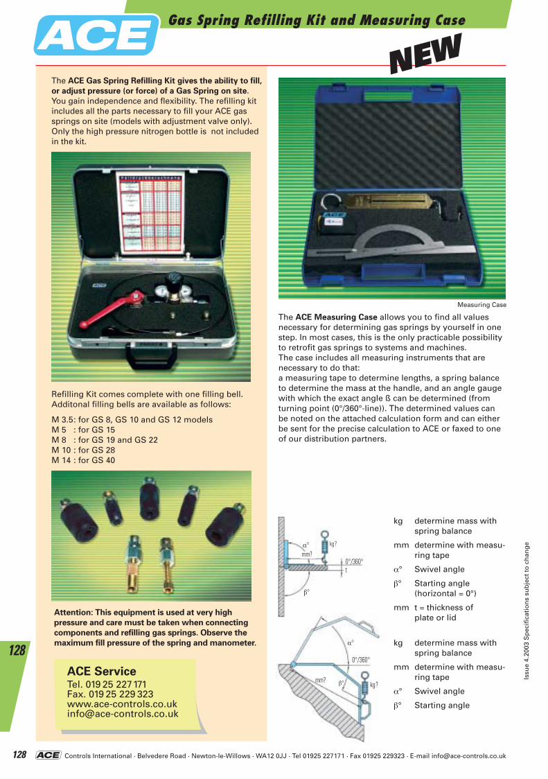
Controls International · Belvedere Road · Newton-le-Willows · WA12 0JJ · Tel 01925 227171 · Fax 01925 229323 · E-mail [email protected]
Gas Spring Refilling Kit and Measuring Case
Issu
e 4.
2003
Sp
ecif
icat
ion
s su
bje
ct t
o c
han
ge
128
128
Refilling Kit comes complete with one filling bell.Additonal filling bells are available as follows:
M 3.5: for GS 8, GS 10 and GS 12 modelsM 5 : for GS 15M 8 : for GS 19 and GS 22M 10 : for GS 28M 14 : for GS 40
Attention: This equipment is used at very high
pressure and care must be taken when connecting
components and refilling gas springs. Observe the
maximum fill pressure of the spring and manometer.
The ACE Gas Spring Refilling Kit gives the ability to fill,
or adjust pressure (or force) of a Gas Spring on site.You gain independence and flexibility. The refilling kit includes all the parts necessary to fill your ACE gassprings on site (models with adjustment valve only).Only the high pressure nitrogen bottle is not included in the kit.
The ACE Measuring Case allows you to find all values necessary for determining gas springs by yourself in onestep. In most cases, this is the only practicable possibilityto retrofit gas springs to systems and machines.The case includes all measuring instruments that are necessary to do that:a measuring tape to determine lengths, a spring balanceto determine the mass at the handle, and an angle gaugewith which the exact angle ß can be determined (from turning point (0°/360°-line)). The determined values can be noted on the attached calculation form and can eitherbe sent for the precise calculation to ACE or faxed to oneof our distribution partners.
kg determine mass withspring balance
mm determine with measu-ring tape
α° Swivel angle
β° Starting angle (horizontal = 0°)
mm t = thickness of plate or lid
kg determine mass withspring balance
mm determine with measu-ring tape
α° Swivel angle
β° Starting angle
ACE ServiceTel. 019 25 227171Fax. 019 25 229 [email protected]
α°
α°
β°
β°
t0°/360°
0°/360°
kg?
kg?
mm?
mm?
Measuring Case
NEW
ACE-Kat_2003_UK_128-130 23.09.2003 9:38 Uhr Seite 128
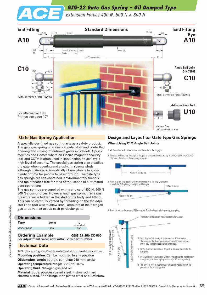
Controls International · Belvedere Road · Newton-le-Willows · WA12 0JJ · Tel 01925 227171 · Fax 01925 229323 · E-mail [email protected]
GSG-22 Gate Gas Spring – Oil Damped TypeExtension Forces 400 N, 500 N & 800 N
Issu
e 4.
2003
Sp
ecif
icat
ion
s su
bje
ct t
o c
han
ge
129
A specially designed gas spring acts as a safety product.The gate gas spring provides a steady, slow and controlledopening and closing of entrance gates in Schools, Sports facilities and Homes where an Electro-magnetic securitylock and CCTV is often used in conjunction, to achieve ahigh level of security. The special gas spring also steadiesthe gate when opening and closing in strong winds, although it always automatically closes slowly to allowplenty of time tor people to pass through. The gate typegas springs are self-contained, environmentaly friendlyand maintenance free for tens of thousands of automatedgate operations.The gas springs are supplied with a choice of 400 N, 500 N800 N ciosing forces. However each gas spring has a gas pressure valve hidden in the stud of the body end fitting.This can be carefully vented by threading on the the adju-ster knob tool U10 to allow small amounts of the nitrogengas to be vented to suit each particular gate.
Eye
13
3535M10
16
∅24 ∅16
18
20
36°
25 L+/- 2 mm extended 25
∅18 ∅ 8,1
17 ∅25 mm Dia. Shroud
∅ 8,1
StrokeBallR 9
12 thick 12 thick
∅22 17
End Fitting Standard Dimensions End Fitting
A10
C10 Angle Ball JointDIN 71802
C10
Adjuster Knob Tool
U10
A10
(Max. permitted force 1600 N)(Max. permitted force 1600 N)
Hidden Gaspressure vent value
For alternative End fittings see page 107
L+/- 2 mm extended
BallR 9
12 thick
Stroke
12 thick
Type Stroke L extended
GSG-22-250 250 695
Dimensions
Gate Gas Spring Application
Technical Data
Ordering Example GSG-22-250-CC-500For adjustment valve add suffix -V to part number.
ACE gas springs are self-contained and maintenance free.Mounting position: Can be mounted in any position Oildamping length: approx. complete 250 mm stroke Operating temperature range: -20°C to +80°COperating fluid: Nitrogen gas and oilMaterial: Body: powder coated steel. Piston rod: hard chrome plated. End fittings: zinc plated steel or aluminium.
Design and Layout tor Gate type Gas Springs
When Using C1O Angle Ball Joints
1) All dimensions and points are taken from the centre of the hinge pin.
2) Choose a position along the length of the gate for the point of the gas spring, (e.g. 600 mm, 650 mm, 675 mm).This forms the radius of the gas spring movement.
3) Allow an offset on this point to give room at the side of the gate for a bracket to attach the C1O right angle ball joint end fitting to.
4) From this point scribe an arc of 765 mm radius. This simulates the fully extended gas spring.
5) With the gate fully open now scribe an arc of 525 mm radius. This simulates the closed gas spring allowing for a small amount of free play. Do not forget the offset on the gate.
6) Where these two arcs cross is the point of the fixed position for the gas spring.
7) By adjusting the radius at step (2) above, the gate can be made to openthrough any reasonable angle you choose (i.e. 90 or more, or less)
8) The forces to open or close the gate can be adjusted by altering the geometry of the mounting points.
Radius of Gas Spring
Offset of Spring
Radius of 765 mm
Point at which the gas spring is fixed to the frame, post.
Original radius (Swung through 90°)
Radius of 525 mm
Radius of gas spring closed(W
ith the gate swung through 90°)
ACE-Kat_2003_UK_128-130 23.09.2003 9:39 Uhr Seite 129

Controls International · Belvedere Road · Newton-le-Willows · WA12 0JJ · Tel 01925 227171 · Fax 01925 229323 · E-mail [email protected]
Local Contacts
130
Paul Corkill – Northern AreaAB Aberdeen KY KirkcaldyBB Blackburn IM Isle of ManBD Bradford L LiverpoolBL Bolton LA LancasterCA Carlisle LL LlandudnoCH Chester LS LeedsCW Crewe M ManchesterDD Dundee ML MotherwellDG Dunfries NE NewcastleDH Durham OL OldhamDL Darlington PA PaisleyEH Edinburgh PH PerthFK Falkirk PR PrestonFY Blackpool SK StockportG Glasgow SR SunderlandHD Huddersfield TD GalashieldsHG Harrogate TS ClevelandHX Halifax WA WarringtonIV Inverness WF WakefieldKA Kilmarnock WN WiganKW Kirkwall YO York
Darren Harper – Midlands AreaB Birmingham MK Milton KeynesCV Coventry NG NottinghamDE Derby NN NorthamptonDN Doncaster PE PeterboroughHU Hull S SheffieldLE Leicester ST Stoke on TrentLN Lincoln WS Walsall
Paul Constable – South East AreaAL St. Albans ME MedwayBH Bournemouth NR NorwichBN Brighton PO PortsmouthCB Cambridge RG ReadingCM Chelmsford RH RedhillCO Colchester SG StevenageCT Canterbury SL SloughGU Guildford SO SouthamptonHP Hemel Hempstead SS Southend on SeaIP Ipswich TN TonbridgeLU Luton
All London Postcode Areas
UK Local DistributorsSouth Wales South WestWales Fluid Power Applied Automation
Tel: 029 20 494551 Plymouth
Fax: 029 20 481955 Tel: 01752 343300Fax: 01752 331199
Northern IrelandNorthern Automation Itd Applied AutomationTel: 028 28 270099 Bristol
Fax: 028 28 270080 Tel: 0117 9827769Fax: 0117 9235522
North East Titan Fluid Controls ScotlandTel: 0191 4159555 Macscott Bond
Fax: 0191 4159444 Tel: 0131 4482950Fax: 0131 4482941
East AngliaParker Hydraulics & Pneumatics
Tel: 01603 403190Fax: 01603 485337
Northern EnglandThomas Wright / Thorite Group
Thorite House, Laisterdyke,Bradford BD4 8BZTel: 01274 663471Fax: 01274 668296
Malcolm Sharland – South West AreaBA Bath PL PlymouthBS Bristol SA SwanseaCF Cardiff SN SwindonDY Dudley SP SalisburyDT Dorchester SY ShrewsburyEX Exeter TA TauntonGL Gloucester TF TelfordHR Hereford TQ TorquayLD Llandrindod Wells TR TruroNP Newport WR WorcesterOX Oxford WV Wolverhampton
ACE-Kat_2003_UK_128-130 23.09.2003 9:39 Uhr Seite 130

World Leader in Motion Control
Controls International · Belvedere Road · Newton-le-Willows · WA12 0JJ · Tel 01925 227171 · Fax 01925 229323 · E-mail [email protected] 131
Further Information and Local Contacts
For over 30 years ACE has been
acknowledged as the world leader in
motion control.
It was back in the 1960’s that the thenunique ACE shock absorber was initiallydesigned to serve the Detroit automotive industry. Since then, our world-renowned shock absorbers havegrown to some 100 different models. Inaddition, the ACE motion control rangehas developed to include safety shockabsorbers, rotary dampers, hydraulicdampers, feed controls and industrial gas springs.
LIFETIME WARRANTY
ACE was the first manufacturer in itssector to offer a lifetime warranty on allof its products. ACE products are designed and manufactured to ISO 9001 and are guaranteed to be free from defects in materials or workmanship. ACE will repair or replaceany of its products determined to havea defect in materials or workmanship atany time for the life of the product.
PRODUCT IMPROVEMENT
Due to a continuous product improvement policy, the company reserves the right to change a product’sspecification without notice.
CUSTOMER SUPPORT
ACE employs over 250 people throughout its global network comprising offices in the UK, Germanyand Japan plus distributors in 85 NorthAmerican cities and 33 additional countries.
The UK office carries an extensive stockof products and spare parts, so customers can always rely on a quick and effective service. In addition, the approved ACE distributors and team ofarea managers shown on the inside back cover are always on hand to advise on product selection and any other aspect of the range.
APPLICATION SIMULATION
AND COMPUTER SELECTION
ACE has developed a sophisticated suite of computer software. By combining application data with a shock absorber’s design parameters, ACE engineers can create an accurate picture of how a particular shock absorber will perform under any set ofapplication conditions. Peak reaction force, peak deceleration, time through stroke and velocity decay can be plotted with extreme accuracy (see below). The user benefits by having anyguesswork taken out of sizing decisionsand by knowing before installation, exactly how his shock problem will be solved.
Simulation can also be used to maximise the performance of ACE adjustable models by predicting the ideal adjustment setting for a particulargroup of operating conditions.
Copies of our computer selection programme are available, free of charge. The software provides quick and easy selection of the correct ACE shock absorber for your application.
For more complex or unusual applications full technical support and advice is always freely available.
FAX Request
Company
Address
Postcode.
Telephone/Fax.
Contact name/Dept.
YES! We are interested in:
further copy of the new ACE Catalogue.
the new ACE CAD-Library with Selectionprogramme on CD-Rom. 2D- and 3D-Version (standard formats).
Training at our site.
Technical assistance at our site.
Please quote for: (attach details)
FAX
to 0
1925 2
29323UK Sales Manager
Edward AbbottTel: 07802 232 630Fax: 01270 877002E-mail: [email protected]
ACE Area Managers
NORTH
Paul CorkillTel: 07802 926 431Fax: 0151 283 8710E-mail: [email protected]
MIDLANDS
Darren HarperTel: 07764 357 495Fax: 01623 652 920E-mail: [email protected]
SOUTH EAST
Paul ConstableTel: 07802 926 429Home: 01342 311 171Fax: 01342 316 119E-mail: [email protected]
SOUTH WEST
Malcolm SharlandTel: 07802 926 430Fax: 02920 860 115E-mail: [email protected]