Embed Size (px)
Citation preview
493
AC
AC
DC
Fan
CATALOG No. C1097B001 '20.1.IT
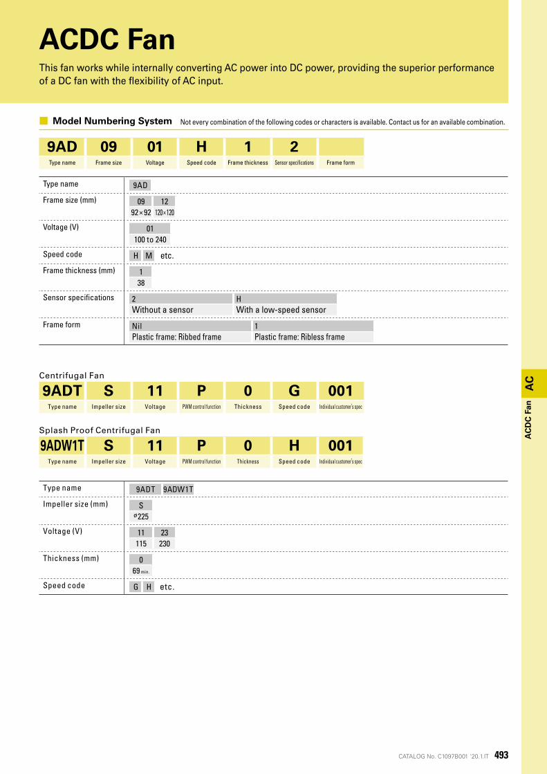
ACDC FanThis fan works while internally converting AC power into DC power, providing the superior performance of a DC fan with the flexibility of AC input.
■ Model Numbering System Not every combination of the following codes or characters is available. Contact us for an available combination.
9AD 09 01 H 1 2Type name Frame size Voltage Speed code Frame thickness Sensor specifications Frame form
Type name 9AD
Frame size (mm) 09 1292×92 120×120
Voltage (V) 01100 to 240
Speed code H M etc.
Frame thickness (mm) 138
Sensor specifications 2 HWithout a sensor With a low-speed sensor
Frame form Nil 1Plastic frame: Ribbed frame Plastic frame: Ribless frame
Centrifugal Fan
9ADT S 11 P 0 G 001Type name Impeller size Voltage PWM control function Thickness Speed code Individual customer’s spec
Splash Proof Centrifugal Fan
9ADW1T S 11 P 0 H 001Type name Impeller size Voltage PWM control function Thickness Speed code Individual customer’s spec
Type name 9ADT 9ADW1T
Impeller size (mm) Sø225
Voltage (V) 11 23115 230
Thickness (mm) 069 min.
Speed code G H etc.
494
AC
CATALOG No. C1097B001 '20.1.IT
AC
DC
Fan
92
mm
sq
.
ACDC Fan
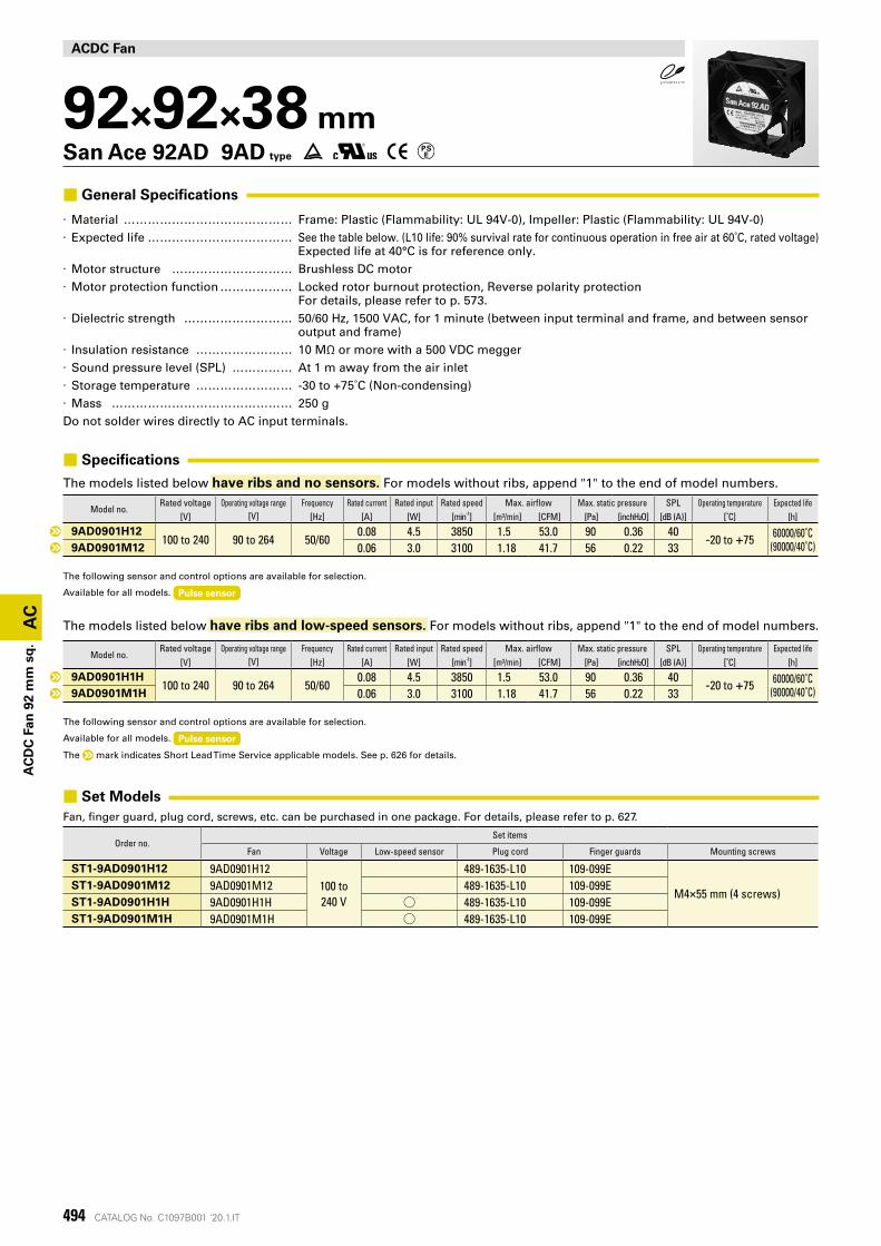
92×92×38 mmSan Ace 92AD 9AD type
■ General Specifications
· Material �������������� Frame: Plastic (Flammability: UL 94V-0), Impeller: Plastic (Flammability: UL 94V-0) · Expected life ������������ See the table below. (L10 life: 90% survival rate for continuous operation in free air at 60˚C, rated voltage)
Expected life at 40°C is for reference only. · Motor structure ���������� Brushless DC motor · Motor protection function ������ Locked rotor burnout protection, Reverse polarity protection
For details, please refer to p. 573. · Dielectric strength ��������� 50/60 Hz, 1500 VAC, for 1 minute (between input terminal and frame, and between sensor
output and frame) · Insulation resistance �������� 10 MΩ or more with a 500 VDC megger · Sound pressure level (SPL) ����� At 1 m away from the air inlet · Storage temperature �������� -30 to +75˚C (Non-condensing) · Mass ��������������� 250 gDo not solder wires directly to AC input terminals.
■ Specifications
The models listed below have ribs and no sensors. For models without ribs, append "1" to the end of model numbers.
Model no.Rated voltage Operating voltage range Frequency Rated current Rated input Rated speed Max. airflow Max. static pressure SPL Operating temperature Expected life
[V] [V] [Hz] [A] [W] [min-1] [m³/min] [CFM] [Pa] [inchH²O] [dB (A)] [˚C] [h]
9AD0901H12100 to 240 90 to 264 50/60
0.08 4.5 3850 1.5 53.0 90 0.36 40-20 to +75 60000/60˚C
(90000/40˚C)9AD0901M12 0.06 3.0 3100 1.18 41.7 56 0.22 33
The following sensor and control options are available for selection.
Available for all models. Pulse sensor
The models listed below have ribs and low-speed sensors. For models without ribs, append "1" to the end of model numbers.
Model no.Rated voltage Operating voltage range Frequency Rated current Rated input Rated speed Max. airflow Max. static pressure SPL Operating temperature Expected life
[V] [V] [Hz] [A] [W] [min-1] [m³/min] [CFM] [Pa] [inchH²O] [dB (A)] [˚C] [h]
9AD0901H1H100 to 240 90 to 264 50/60
0.08 4.5 3850 1.5 53.0 90 0.36 40-20 to +75 60000/60˚C
(90000/40˚C)9AD0901M1H 0.06 3.0 3100 1.18 41.7 56 0.22 33
The following sensor and control options are available for selection.
Available for all models. Pulse sensor
The mark indicates Short Lead Time Service applicable models. See p. 626 for details.
■ Set ModelsFan, finger guard, plug cord, screws, etc. can be purchased in one package. For details, please refer to p. 627.
Order no.Set items
Fan Voltage Low-speed sensor Plug cord Finger guards Mounting screws
ST1-9AD0901H12 9AD0901H12100 to 240 V
489-1635-L10 109-099E
M4×55 mm (4 screws)ST1-9AD0901M12 9AD0901M12 489-1635-L10 109-099EST1-9AD0901H1H 9AD0901H1H ◯ 489-1635-L10 109-099EST1-9AD0901M1H 9AD0901M1H ◯ 489-1635-L10 109-099E
495CATALOG No. C1097B001 '20.1.IT
100~240 V 50/60 Hz
静圧
風量
(inch H2O)
(CFM)
(m3/min)
(Pa)
20
0 0.4 0.8 1.2 1.6
40
60
80
100
100 20 30 40 50
0.1
0
0.2
0.3
0.4
100~240 V 50/60 Hz
静圧
風量
(inch H2O)
(CFM)
(m3/min)
(Pa)
20
0 0.4 0.8 1.2 1.6
10
30
40
50
60
100 20 30 40 50
0.05
0
0.10
0.15
0.20
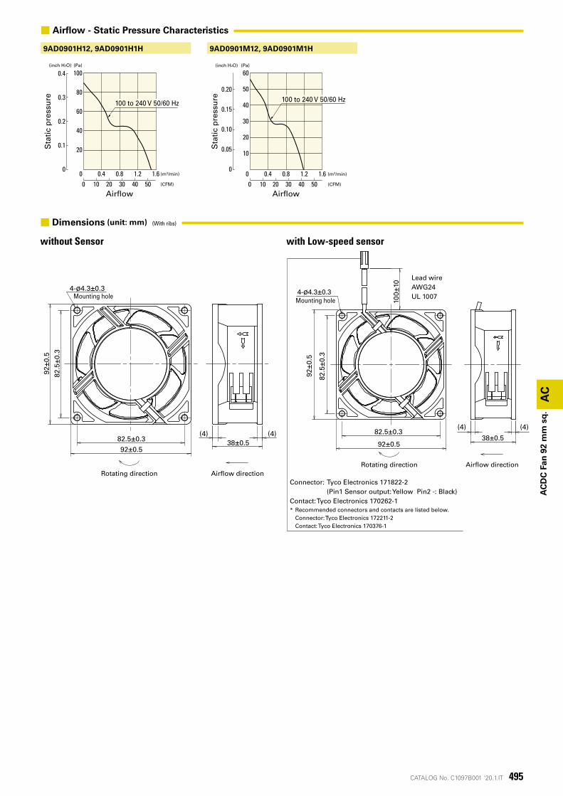
9AD0901M12, 9AD0901M1H9AD0901H12, 9AD0901H1H
回転方向 風吹出方向
取付用穴
38±0.5(4) (4)
82.5±0.3
92±0.5
4-ø4.3±0.3
82.5
±0.3
92±0
.5
回転方向 風吹出方向
リード線AWG24UL 1007
4-ø4.3±0.3取付用穴
コネクタ: Tyco Electronics 171822-2 (Pin.1 センサ出力:黄色 Pin.2 -:黒色)コンタクト:Tyco Electronics 170262-1※装置側のコネクタ・コンタクトは以下を推奨いたします。 コネクタ:Tyco Electronics 172211-2 コンタクト:Tyco Electronics 170376-1
100±
10
82.5±0.3
92±0.538±0.5
(4) (4)
82.5
±0.3
92±0
.5
AC
AC
DC
Fan
92
mm
sq
.
Sta
tic
pre
ssu
re
Sta
tic
pre
ssu
re
Airflow Airflow
100 to 240 V 50/60 Hz 100 to 240 V 50/60 Hz
■ Airflow - Static Pressure Characteristics
without Sensor with Low-speed sensor
Rotating direction
Mounting holeMounting hole
Airflow directionRotating direction Airflow direction
Lead wireAWG24UL 1007
Connector: Tyco Electronics 171822-2 (Pin1 Sensor output: Yellow Pin2 -: Black)Contact: Tyco Electronics 170262-1* Recommended connectors and contacts are listed below. Connector: Tyco Electronics 172211-2 Contact: Tyco Electronics 170376-1
■ Dimensions (unit: mm) (With ribs)
496
AC
CATALOG No. C1097B001 '20.1.IT
4-ø4.54-ø4.5
ø105
90.5
90.5
ø97
82.5±0.3 82.5±0.3
82.5
±0.3
82.5
±0.3
90.5
90.5
AC
DC
Fan
92
mm
sq
.
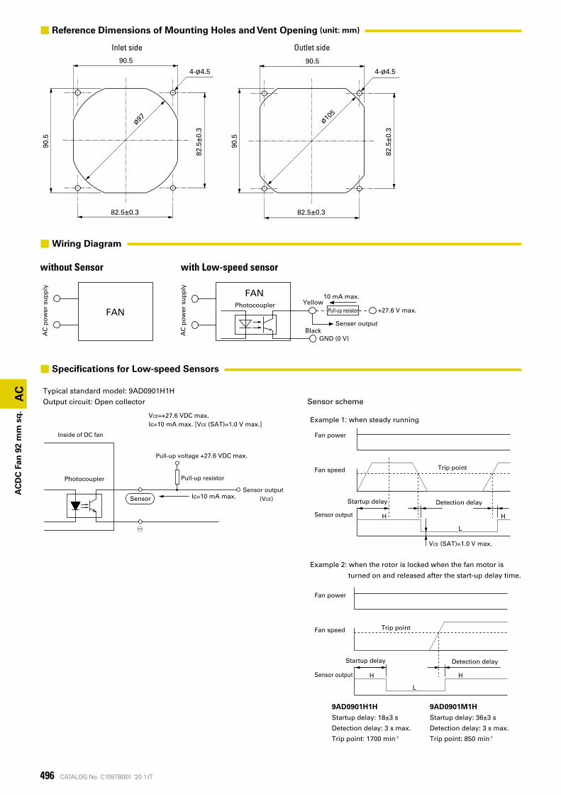
VCE=+27.6 VDC max.Ic=10 mA max. [VCE (SAT)=1.0 V max.]
Sensor scheme
HH
L
Fan power
Fan speed Trip point
Sensor output
Startup delay Detection delay
Example 2: when the rotor is locked when the fan motor is
turned on and released after the start-up delay time.
HH
L
Fan power
Fan speed Trip point
Sensor output
Startup delay Detection delay
Example 1: when steady running
VCE (SAT)=1.0 V max.
Typical standard model: 9AD0901H1HOutput circuit: Open collector
Inside of DC fan
Pull-up resistor
Pull-up voltage +27.6 VDC max.
Photocoupler
○-
Ic=10 mA max.SensorSensor output
(VCE)
9AD0901M1HStartup delay: 36±3 s
Detection delay: 3 s max.
Trip point: 850 min-1
9AD0901H1HStartup delay: 18±3 s
Detection delay: 3 s max.
Trip point: 1700 min-1
■ Specifications for Low-speed Sensors
Inlet side Outlet side
■ Reference Dimensions of Mounting Holes and Vent Opening (unit: mm)
FAN
FANPhotocoupler Yellow
Black
10 mA max.
+27.6 V max.
Senser output
GND (0 V)
AC
po
wer
su
pp
ly
AC
po
wer
su
pp
ly
Pull-up resistor
■Wiring Diagram
without Sensor with Low-speed sensor
497CATALOG No. C1097B001 '20.1.IT
AC
AC
DC
Fan
92
mm
sq
.
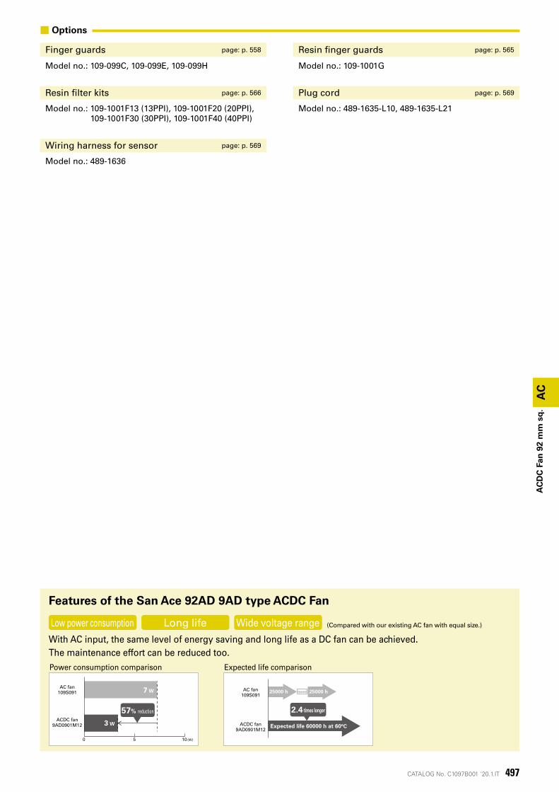
■ Options
Finger guards page: p. 558 Resin finger guards page: p. 565
Model no.: 109-099C, 109-099E, 109-099H Model no.: 109-1001G
Resin filter kits page: p. 566 Plug cord page: p. 569
Model no.: 109-1001F13 (13PPI), 109-1001F20 (20PPI), 109-1001F30 (30PPI), 109-1001F40 (40PPI)
Model no.: 489-1635-L10, 489-1635-L21
Wiring harness for sensor page: p. 569
Model no.: 489-1636
With AC input, the same level of energy saving and long life as a DC fan can be achieved.The maintenance effort can be reduced too.
Features of the San Ace 92AD 9AD type ACDC Fan
Power consumption comparison Expected life comparison
Low power consumption Long life Wide voltage range (Compared with our existing AC fan with equal size.)
0 5 10(W)
3 W
7 WAC fan
109S091
ACDC fan9AD0901M12
57% reduction
AC fan109S091
ACDC fan9AD0901M12
Expected life 60000 h at 60°C
2.4 times longer
25000 h 25000 hReplacement
AC
498 CATALOG No. C1097B001 '20.1.IT
AC
DC
Fan
120
mm
sq
.
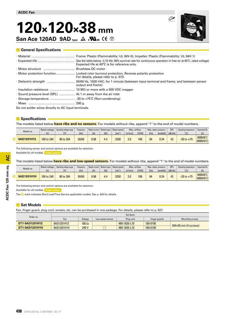
ACDC Fan
120×120×38 mmSan Ace 120AD 9AD type
■ General Specifications
· Material �������������� Frame: Plastic (Flammability: UL 94V-0), Impeller: Plastic (Flammability: UL 94V-1) · Expected life ������������ See the table below. (L10 life: 90% survival rate for continuous operation in free air at 60˚C, rated voltage)
Expected life at 40°C is for reference only. · Motor structure ���������� Brushless DC motor · Motor protection function ������ Locked rotor burnout protection, Reverse polarity protection
For details, please refer to p. 573. · Dielectric strength ��������� 50/60 Hz, 1500 VAC, for 1 minute (between input terminal and frame, and between sensor
output and frame) · Insulation resistance �������� 10 MΩ or more with a 500 VDC megger · Sound pressure level (SPL) ����� At 1 m away from the air inlet · Storage temperature �������� -30 to +75˚C (Non-condensing) · Mass ��������������� 290 gDo not solder wires directly to AC input terminals.
■ SpecificationsThe models listed below have ribs and no sensors. For models without ribs, append "1" to the end of model numbers.
Model no.Rated voltage Operating voltage range Frequency Rated current Rated input Rated speed Max. airflow Max. static pressure SPL Operating temperature Expected life
[V] [V] [Hz] [A] [W] [min-1] [m³/min] [CFM] [Pa] [inchH²O] [dB (A)] [˚C] [h]
9AD1201H12 100 to 240 90 to 264 50/60 0.08 4.4 3250 3.0 106 84 0.34 42 -20 to +75 60000/60˚C(90000/40˚C)
The following sensor and control options are available for selection.
Available for all models. Pulse sensor
The models listed below have ribs and low-speed sensors. For models without ribs, append "1" to the end of model numbers.
Model no.Rated voltage Operating voltage range Frequency Rated current Rated input Rated speed Max. airflow Max. static pressure SPL Operating temperature Expected life
[V] [V] [Hz] [A] [W] [min-1] [m³/min] [CFM] [Pa] [inchH²O] [dB (A)] [˚C] [h]
9AD1201H1H 100 to 240 90 to 264 50/60 0.08 4.4 3250 3.0 106 84 0.34 42 -20 to +75 60000/60˚C(90000/40˚C)
The following sensor and control options are available for selection.
Available for all models. Pulse sensor
The mark indicates Short Lead Time Service applicable models. See p. 626 for details.
■ Set ModelsFan, finger guard, plug cord, screws, etc. can be purchased in one package. For details, please refer to p. 627.
Order no.Set items
Fan Voltage Low-speed sensor Plug cord Finger guards Mounting screws
ST1-9AD1201H12 9AD1201H12 100 to 240 V
489-1635-L10 109-019EM4×55 mm (4 screws)
ST1-9AD1201H1H 9AD1201H1H ◯ 489-1635-L10 109-019E
499CATALOG No. C1097B001 '20.1.IT
(Pa)(inch H2O)
静圧
(CFM)
(m3/min)
風量
90
50
70
60
80
40
30
10
20
0 1 2 3 4
0 50 100 150
0.4
0.2
0.3
0.1
0
100~ 240 V 50/60 Hz
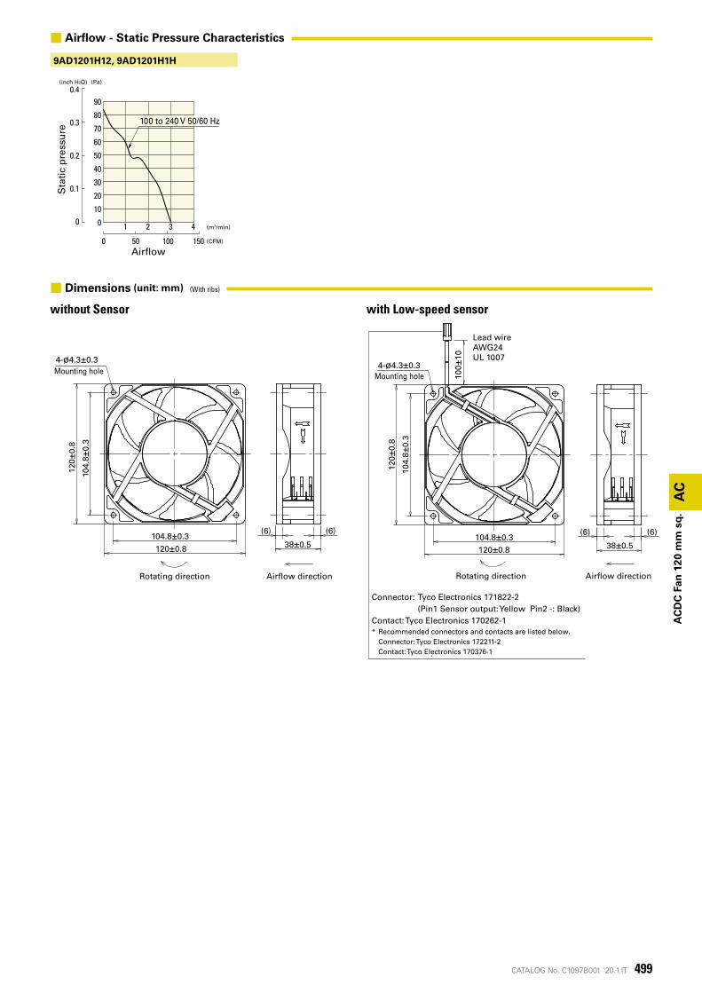
9AD1201H12, 9AD1201H1H
回転方向 風吹出方向
取付用穴
120±0.8
120±
0.8
104.8±0.3
104.
8±0.
3
4-ø4.3±0.3
38±0.5
(6)(6)
回転方向 風吹出方向
リード線AWG24UL 1007
120±0.8
120±
0.8
104.8±0.3
104.
8±0.
3
4-ø4.3±0.3
100±
10
38±0.5
(6)(6)
取付用穴
コネクタ: Tyco Electronics 171822-2 (Pin.1 センサ出力:黄色 Pin.2 -:黒色)コンタクト:Tyco Electronics 170262-1※装置側のコネクタ・コンタクトは以下を推奨いたします。 コネクタ:Tyco Electronics 172211-2 コンタクト:Tyco Electronics 170376-1
AC
AC
DC
Fan
120
mm
sq
.
Sta
tic
pre
ssu
re
Airflow
100 to 240 V 50/60 Hz
■ Airflow - Static Pressure Characteristics
without Sensor with Low-speed sensor
Rotating direction
Mounting holeMounting hole
Airflow direction Rotating direction Airflow direction
Lead wireAWG24UL 1007
Connector: Tyco Electronics 171822-2 (Pin1 Sensor output: Yellow Pin2 -: Black)Contact: Tyco Electronics 170262-1* Recommended connectors and contacts are listed below. Connector: Tyco Electronics 172211-2 Contact: Tyco Electronics 170376-1
■ Dimensions (unit: mm) (With ribs)
AC
500 CATALOG No. C1097B001 '20.1.IT
ø135
104.8±0.34-ø4.5
118
104.
8±0.
3
118
ø127
104.8±0.34-ø4.5
118
104.
8±0.
3
118
AC
DC
Fan
120
mm
sq
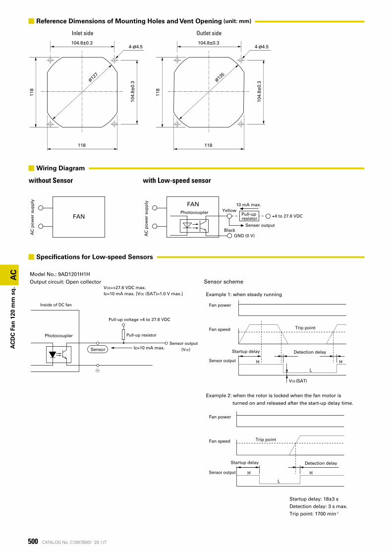
. VCE=+27.6 VDC max.Ic=10 mA max. [VCE (SAT)=1.0 V max.]
Sensor scheme
HH
L
Fan power
Fan speed Trip point
Sensor output
Startup delay Detection delay
Example 2: when the rotor is locked when the fan motor is
turned on and released after the start-up delay time.
HH
L
Fan power
Fan speed Trip point
Sensor output
Startup delay Detection delay
Example 1: when steady running
VCE (SAT)
Model No.: 9AD1201H1HOutput circuit: Open collector
Inside of DC fan
Pull-up resistor
Pull-up voltage +4 to 27.6 VDC
Photocoupler
○-
Ic=10 mA max.SensorSensor output
(VCE)
Startup delay: 18±3 s
Detection delay: 3 s max.
Trip point: 1700 min-1
■ Specifications for Low-speed Sensors
Inlet side Outlet side
■ Reference Dimensions of Mounting Holes and Vent Opening (unit: mm)
FAN
FANPhotocoupler Yellow
Black
Pull-up resistor
10 mA max.
AC
po
wer
su
pp
ly
AC
po
wer
su
pp
ly
+4 to 27.6 VDC
Senser output
GND (0 V)
with Low-speed sensorwithout Sensor
■Wiring Diagram
501CATALOG No. C1097B001 '20.1.IT
AC
AC
DC
Fan
120
mm
sq
.
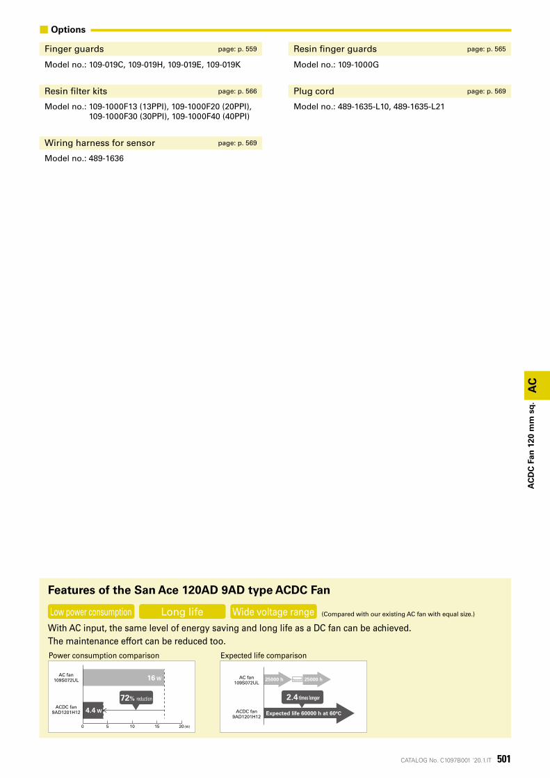
■ Options
Finger guards page: p. 559 Resin finger guards page: p. 565
Model no.: 109-019C, 109-019H, 109-019E, 109-019K Model no.: 109-1000G
Resin filter kits page: p. 566 Plug cord page: p. 569
Model no.: 109-1000F13 (13PPI), 109-1000F20 (20PPI), 109-1000F30 (30PPI), 109-1000F40 (40PPI)
Model no.: 489-1635-L10, 489-1635-L21
Wiring harness for sensor page: p. 569
Model no.: 489-1636
With AC input, the same level of energy saving and long life as a DC fan can be achieved.The maintenance effort can be reduced too.
Features of the San Ace 120AD 9AD type ACDC Fan
Power consumption comparison Expected life comparison
Low power consumption Long life Wide voltage range (Compared with our existing AC fan with equal size.)
0 5 10 15 20 (W)
4.4 W
16 WAC fan
109S072UL
ACDC fan9AD1201H12
72% reduction
AC fan109S072UL
ACDC fan9AD1201H12
Expected life 60000 h at 60°C
2.4 times longer
25000 h 25000 hReplacement
AC
502 CATALOG No. C1097B001 '20.1.IT
AC
DC
Fan
ø22
5 m
m
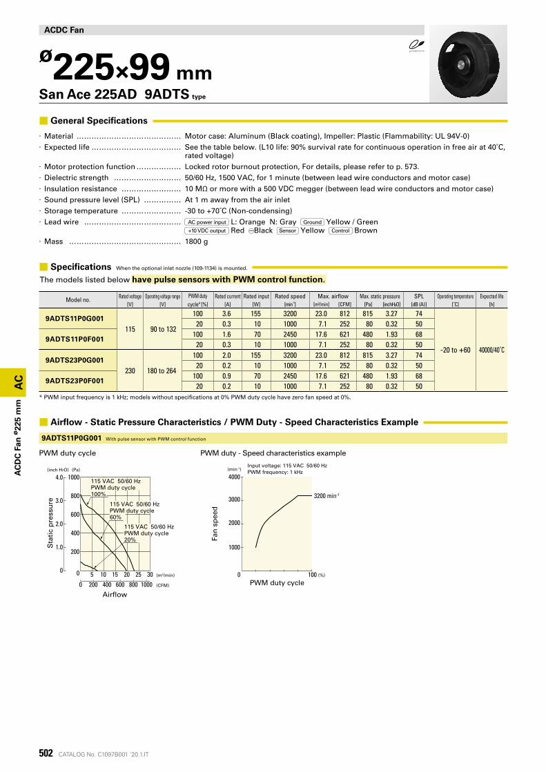
Model no. Rated voltage Operating voltage range PWM duty cycle* [%]
Rated current Rated input Rated speed Max. airflow Max. static pressure SPL Operating temperature Expected life[V] [V] [A] [W] [min-1] [m³/min] [CFM] [Pa] [inchH²O] [dB (A)] [˚C] [h]
9ADTS11P0G001
115 90 to 132
100 3.6 155 3200 23.0 812 815 3.27 74
-20 to +60 40000/40˚C
20 0.3 10 1000 7.1 252 80 0.32 50
9ADTS11P0F001100 1.6 70 2450 17.6 621 480 1.93 68
20 0.3 10 1000 7.1 252 80 0.32 50
9ADTS23P0G001
230 180 to 264
100 2.0 155 3200 23.0 812 815 3.27 7420 0.2 10 1000 7.1 252 80 0.32 50
9ADTS23P0F001100 0.9 70 2450 17.6 621 480 1.93 68
20 0.2 10 1000 7.1 252 80 0.32 50* PWM input frequency is 1 kHz; models without specifications at 0% PWM duty cycle have zero fan speed at 0%.
ACDC Fan
ø225×99 mmSan Ace 225AD 9ADTS type
■ General Specifications
· Material �������������� Motor case: Aluminum (Black coating), Impeller: Plastic (Flammability: UL 94V-0) · Expected life ������������ See the table below. (L10 life: 90% survival rate for continuous operation in free air at 40˚C,
rated voltage) · Motor protection function ������ Locked rotor burnout protection, For details, please refer to p. 573. · Dielectric strength ��������� 50/60 Hz, 1500 VAC, for 1 minute (between lead wire conductors and motor case) · Insulation resistance �������� 10 MΩ or more with a 500 VDC megger (between lead wire conductors and motor case) · Sound pressure level (SPL) ����� At 1 m away from the air inlet · Storage temperature �������� -30 to +70˚C (Non-condensing) · Lead wire ������������� AC power input L: Orange N: Gray Ground Yellow / Green
+10 VDC output Red Black Sensor Yellow Control Brown · Mass ��������������� 1800 g
■ Specifications When the optional inlet nozzle (109-1134) is mounted.
The models listed below have pulse sensors with PWM control function.
PWM duty cycle PWM duty - Speed characteristics example
■ Airflow - Static Pressure Characteristics / PWM Duty - Speed Characteristics Example
9ADTS11P0G001 With pulse sensor with PWM control function
Sta
tic
pre
ssu
re
Air�ow
(Pa)(inch H2O)
(CFM)
(m3/min)50 10 2015 25 30
0 200 600 800400
0
1000
200
400
1000
600
800
1.0
2.0
3.0
4.0115 VAC 50/60 HzPWM duty cycle100%
115 VAC 50/60 HzPWM duty cycle60%
115 VAC 50/60 HzPWM duty cycle20%
(min-1)
Fan
sp
eed
PWM duty cycle0 (%)100
Input voltage: 115 VAC 50/60 HzPWM frequency: 1 kHz
3200 min-1
1000
3000
4000
2000
503CATALOG No. C1097B001 '20.1.IT
AC
AC
DC
Fan
ø22
5 m
m
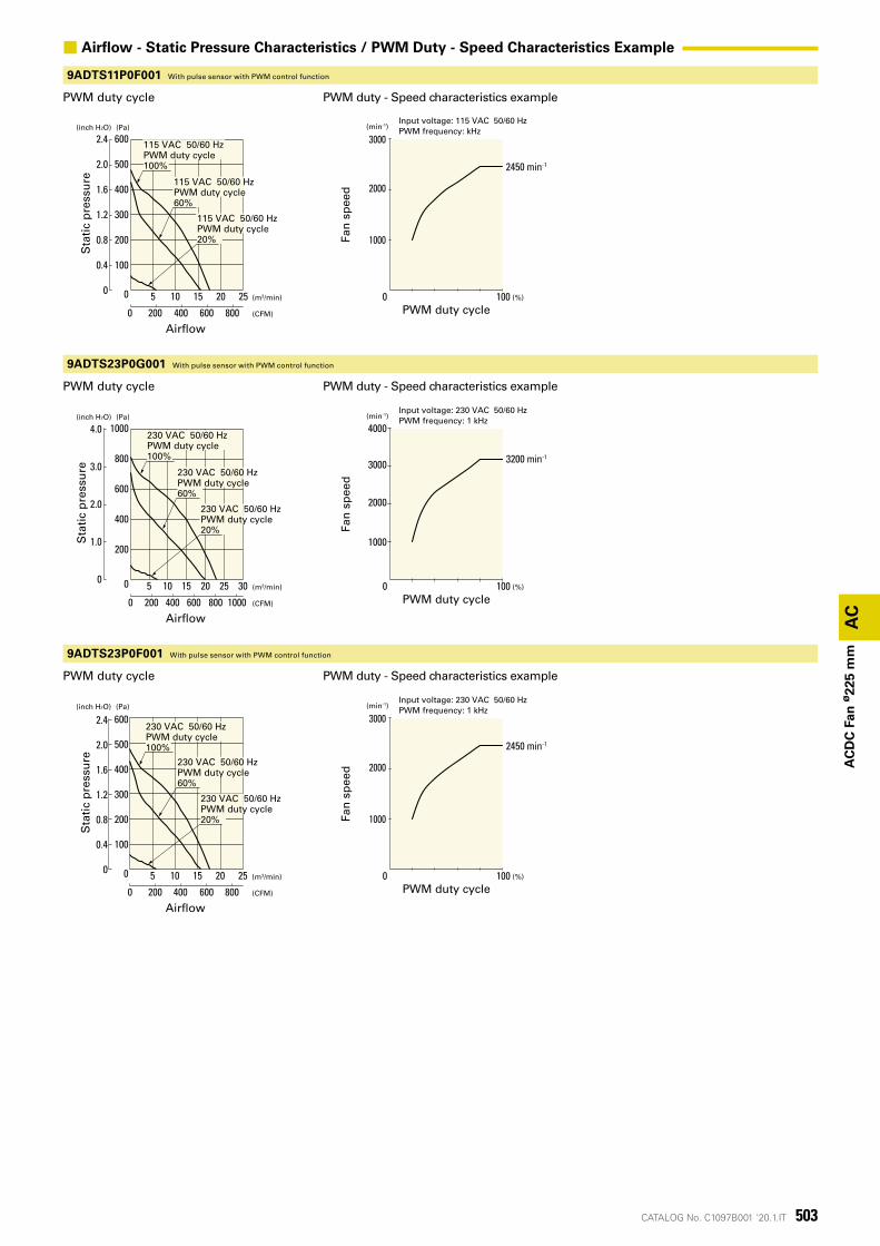
9ADTS11P0F001 With pulse sensor with PWM control function
PWM duty cycle PWM duty - Speed characteristics example
PWM duty cycle
PWM duty cycle
PWM duty - Speed characteristics example
PWM duty - Speed characteristics example
9ADTS23P0G001 With pulse sensor with PWM control function
9ADTS23P0F001 With pulse sensor with PWM control function
■ Airflow - Static Pressure Characteristics / PWM Duty - Speed Characteristics Example
Sta
tic
pre
ssu
re
Air�ow
(Pa)(inch H2O)
(CFM)
(m3/min)0
600
300
400
500
200
100
0 200 600400
0
800
5 10 15 20
0.8
1.2
0.4
1.6
2.0
2.4
25
115 VAC 50/60 HzPWM duty cycle100%
115 VAC 50/60 HzPWM duty cycle60%
115 VAC 50/60 HzPWM duty cycle20%
(min-1)
Fan
sp
eed
PWM duty cycle0 (%)100
Input voltage: 115 VAC 50/60 HzPWM frequency: kHz
2450 min-1
1000
3000
2000
Sta
tic
pre
ssu
re
Air�ow
(Pa)(inch H2O)
(CFM)
(m3/min)0
1.0
2.0
3.0
4.0
0 200 600 800400 1000
5
200
0
400
10 2015 25
1000
600
800
30
230 VAC 50/60 HzPWM duty cycle100%
230 VAC 50/60 HzPWM duty cycle60%
230 VAC 50/60 HzPWM duty cycle20%
Sta
tic
pre
ssu
re
Air�ow
(Pa)(inch H2O)
(CFM)
(m3/min)
0 200 600400
0
800
50 10 15 20
600
300
400
500
200
100
0.8
1.2
0.4
1.6
2.0
2.4
25
230 VAC 50/60 HzPWM duty cycle100%
230 VAC 50/60 HzPWM duty cycle60%
230 VAC 50/60 HzPWM duty cycle20%
(min-1)
Fan
sp
eed
PWM duty cycle0 (%)100
Input voltage: 230 VAC 50/60 HzPWM frequency: 1 kHz
3200 min-1
1000
3000
4000
2000
(min-1)
Fan
sp
eed
PWM duty cycle0 (%)100
Input voltage: 230 VAC 50/60 HzPWM frequency: 1 kHz
2450 min-1
1000
3000
2000
AC
504 CATALOG No. C1097B001 '20.1.IT
AC
DC
Fan
ø22
5 m
m
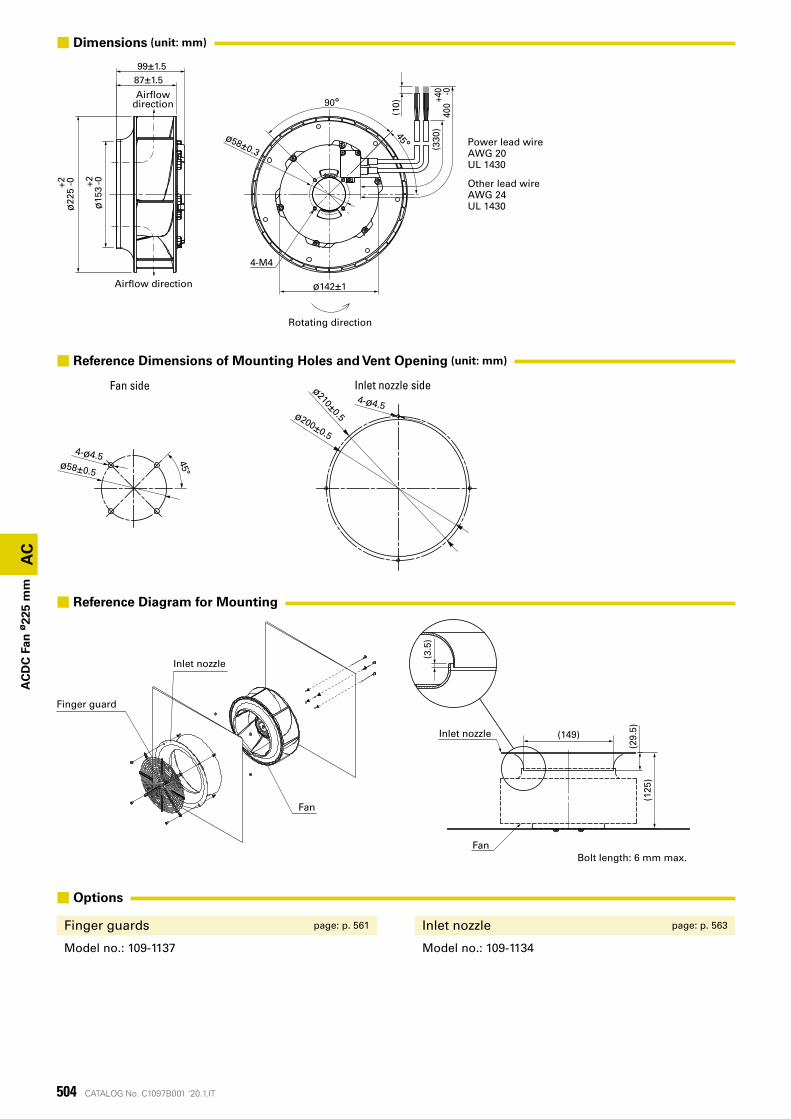
Finger guard
Inlet nozzle
Fan
(3.5
)
Fan
Inlet nozzle (149)
(29.
5 )(1
25)
Bolt length: 6 mm max.
Inlet nozzle sideFan side
4-ø4.5 45°ø58±0.5
4-ø4.5ø200±0.5
ø210±0.5
Power lead wireAWG 20UL 1430
Other lead wireAWG 24UL 1430
Rotating direction
Air�ow direction
Air�owdirection
4-M4
87±1.5
ø15
3+2 -0
ø22
5+2 -0
99±1.5
ø58±0.3
ø142±1
90°
45°
(330
)40
0+4
0 -0
(10)
■ Options
Finger guards page: p. 561 Inlet nozzle page: p. 563
Model no.: 109-1137 Model no.: 109-1134
■ Reference Diagram for Mounting
■ Reference Dimensions of Mounting Holes and Vent Opening (unit: mm)
■ Dimensions (unit: mm)
505CATALOG No. C1097B001 '20.1.IT
AC
AC
DC
Fan
ø22
5 m
m
IP56
ACDC Fan
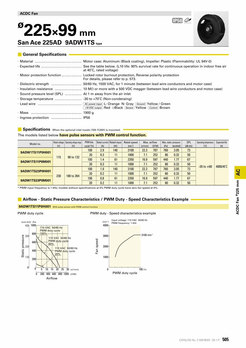
ø225×99 mmSan Ace 225AD 9ADW1TS type
■ General Specifications
· Material �������������� Motor case: Aluminum (Black coating), Impeller: Plastic (Flammability: UL 94V-0) · Expected life ������������ See the table below. (L10 life: 90% survival rate for continuous operation in indoor free air
at 40˚C, rated voltage) · Motor protection function ������ Locked rotor burnout protection, Reverse polarity protection
For details, please refer to p. 573. · Dielectric strength ��������� 50/60 Hz, 1500 VAC, for 1 minute (between lead wire conductors and motor case) · Insulation resistance �������� 10 MΩ or more with a 500 VDC megger (between lead wire conductors and motor case) · Sound pressure level (SPL) ����� At 1 m away from the air inlet · Storage temperature �������� -30 to +70˚C (Non-condensing) · Lead wire ������������� AC power input L: Orange N: Gray Ground Yellow / Green
+10 VDC output Red Black Sensor Yellow Control Brown · Mass ��������������� 1900 g · Ingress protection ��������� IP56
■ Specifications When the optional inlet nozzle (109-1134H) is mounted.
The models listed below have pulse sensors with PWM control function.
PWM duty cycle PWM duty - Speed characteristics example
■ Airflow - Static Pressure Characteristics / PWM Duty - Speed Characteristics Example
9ADW1TS11P0H001 With pulse sensor with PWM control function
Model no. Rated voltage Operating voltage range PWM duty cycle* [%]
Rated current Rated input Rated speed Max. airflow Max. static pressure SPL Operating temperature Expected life[V] [V] [A] [W] [min-1] [m³/min] [CFM] [Pa] [inchH²O] [dB (A)] [˚C] [h]
9ADW1TS11P0H001
115 90 to 132
100 2.9 140 3100 22.3 787 760 3.05 73
-20 to +60 40000/40˚C
20 0.3 11 1000 7.1 252 80 0.32 50
9ADW1TS11P0M001100 1.4 61 2350 16.9 597 440 1.77 67
20 0.3 11 1000 7.1 252 80 0.32 50
9ADW1TS23P0H001
230 180 to 264
100 1.9 140 3100 22.3 787 760 3.05 7320 0.2 11 1000 7.1 252 80 0.32 50
9ADW1TS23P0M001100 0.8 61 2350 16.9 597 440 1.77 67
20 0.2 11 1000 7.1 252 80 0.32 50* PWM input frequency is 1 kHz; models without specifications at 0% PWM duty cycle have zero fan speed at 0%.
Sta
tic
pre
ssu
re
Air�ow
(Pa)(inch H2O)
(CFM)
(m3/min)
0 200 600 800400
0
1000
5
200
0
400
10 2015 25
1000
600
800
1.0
2.0
3.0
4.0
30
115 VAC 50/60 HzPWM duty cycle100%
115 VAC 50/60 HzPWM duty cycle60%
115 VAC 50/60 HzPWM duty cycle20%
(min-1)
Fan
sp
eed
PWM duty cycle0 (%)100
Input voltage: 115 VAC 50/60 HzPWM frequency: 1 kHz
3100 min-1
1000
3000
4000
2000
AC
506 CATALOG No. C1097B001 '20.1.IT
AC
DC
Fan
ø22
5 m
m
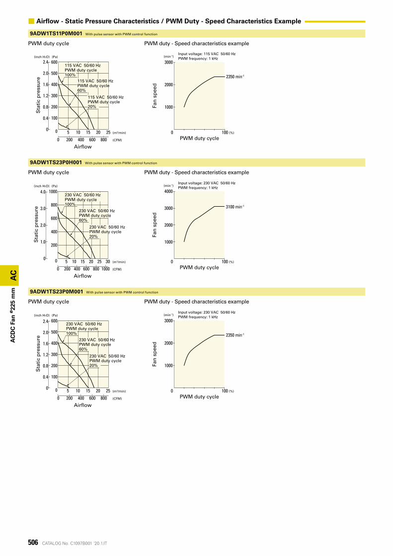
9ADW1TS11P0M001 With pulse sensor with PWM control function
PWM duty cycle PWM duty - Speed characteristics example
PWM duty cycle
PWM duty cycle
PWM duty - Speed characteristics example
PWM duty - Speed characteristics example
9ADW1TS23P0H001 With pulse sensor with PWM control function
9ADW1TS23P0M001 With pulse sensor with PWM control function
■ Airflow - Static Pressure Characteristics / PWM Duty - Speed Characteristics Example
Sta
tic
pre
ssu
re
Air�ow
(Pa)(inch H2O)
(CFM)
(m3/min)
0 200 600400
0
800
50 10 15 20
600
300
400
500
200
100
0.8
1.2
0.4
1.6
2.0
2.4
25
115 VAC 50/60 HzPWM duty cycle100%
115 VAC 50/60 HzPWM duty cycle60%
115 VAC 50/60 HzPWM duty cycle20%
(min-1)
Fan
sp
eed
PWM duty cycle0 (%)100
Input voltage: 115 VAC 50/60 HzPWM frequency: 1 kHz
2350 min-1
1000
3000
2000
Sta
tic
pre
ssu
re
Air�ow
(Pa)(inch H2O)
(CFM)
(m3/min)
0 200 600 800400
0
1000
5
200
400
10 2015 25
1000
600
800
1.0
2.0
3.0
4.0
300
230 VAC 50/60 HzPWM duty cycle100%
230 VAC 50/60 HzPWM duty cycle60%
230 VAC 50/60 HzPWM duty cycle20%
Sta
tic
pre
ssu
re
Air�ow
(Pa)(inch H2O)
(CFM)
(m3/min)
0 200 600400
0
800
50 10 15 20
600
300
400
500
200
100
0.8
1.2
0.4
1.6
2.0
2.4
25
230 VAC 50/60 HzPWM duty cycle100%
230 VAC 50/60 HzPWM duty cycle60%
230 VAC 50/60 HzPWM duty cycle20%
(min-1)
Fan
sp
eed
PWM duty cycle0 (%)100
Input voltage: 230 VAC 50/60 HzPWM frequency: 1 kHz
3100 min-1
1000
3000
4000
2000
(min-1)
Fan
sp
eed
PWM duty cycle0 (%)100
Input voltage: 230 VAC 50/60 HzPWM frequency: 1 kHz
2350 min-1
1000
3000
2000
507CATALOG No. C1097B001 '20.1.IT
AC
AC
DC
Fan
ø22
5 m
m
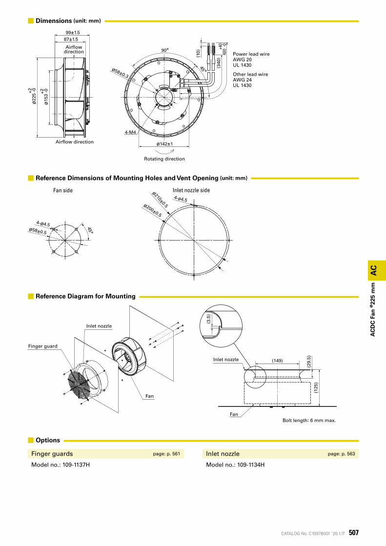
■ Dimensions (unit: mm)
■ Reference Dimensions of Mounting Holes and Vent Opening (unit: mm)
■ Options
Finger guards page: p. 561 Inlet nozzle page: p. 563
Model no.: 109-1137H Model no.: 109-1134H
■ Reference Diagram for Mounting
4-M4
87±1.5ø
153+2 -0
ø22
5+2 -099±1.5
ø58±0.3
ø142±1
90°
45°
(340
)40
0+40 -0
(10)
Rotating direction
Air�ow direction
Air�owdirection Power lead wire
AWG 20UL 1430
Other lead wireAWG 24UL 1430
Inlet nozzle sideFan side
4-ø4.5 45°ø58±0.5
4-ø4.5ø200±0.5
ø210±0.5
Finger guard
Inlet nozzle
Fan
(3.5
)
Fan
Inlet nozzle (149)
(29.
5 )(1
25)
Bolt length: 6 mm max.

508 CATALOG No. C1097B001 '20.1.IT
CATALOG No. C1097B001 '20.1.IT 509
AC
AC
Fan
AC FanThe cooling fan operates at 100 to 230 VAC.
510 CATALOG No. C1097B001 '20.1.IT
(Pa)(inch H2O)
静圧
風量(CFM)
(m3/min) 0
10
20
0.2 0.4
30
0
0.02
0.04
0.06
0.08
0.10
0.12
0 5 10 15
60 Hz 100 V/115 V
50 Hz 100 V/115 V
109-180, 109-183
AC
AC
Fan
60
mm
sq
.
Sta
tic
pre
ssu
re
Airflow
AC Fan
60×60×28 mmSan Ace 60
■ General Specifications
· Material �������������� Frame: Aluminum, Impeller: Plastic (Flammability: UL 94V-1) · Expected life ������������ See the table below. (L10 life: 90% survival rate for continuous operation in free air at 60˚C, rated voltage)
Expected life at 40°C is for reference only. · Motor structure ���������� Shaded coil motor · Motor protection function ������ Locked rotor burnout protection, Reverse polarity protection
For details, please refer to p. 573. · Dielectric strength ��������� 50/60 Hz, 1500 VAC, for 1 minute (between lead wire conductors and frame) · Insulation resistance �������� 10 MΩ or more with a 500 VDC megger · Sound pressure level (SPL) ����� At 1 m away from the air inlet · Operating voltage range ������ Voltage of each model ±10% · Storage temperature �������� -30 to +70˚C (Non-condensing) · Lead wire ������������� Black, 2 pcs · Mass ��������������� 120 g
■ Specifications
Model no. Rated voltage Frequency Input Current Locked rotor current Rated speed Max. airflow Max. static pressure SPL Operating temperature Expected life[V] [Hz] [W] [A] [A] [min-1] [m³/min] [CFM] [Pa] [inchH²O] [dB (A)] [˚C] [h]
109-180 10050/60 5/4 0.06/0.05
0.07/0.062250/2700 0.27/0.33 9.5/11.7 11.8/18.6 0.047/0.075 24/26 -30 to +70 25000/60˚C
(56000/40˚C)109-183 115 0.06/0.05
These are Short Lead Time Service applicable models. Contact your point of sale for stock availability. For more information on the service, see p. 626.
■ Set ModelsFan, finger guard, plug cord, screws, etc. can be purchased in one package. For details, please refer to p. 627.
Order no.Set items
Fan Voltage Low-speed sensor Plug cord Finger guards Mounting screws
ST1-109-180 109-180 100 V Plug cord is not included because of the exposed-lead structure.
109-139EM4×40 mm (4 screws)
ST1-109-183 109-183 115 V 109-139E
■ Airflow - Static Pressure Characteristics

511CATALOG No. C1097B001 '20.1.IT
8-ø4.3
取付用穴
リード線AWG26UL 1430
60±0.5
50±0.3
+50300 0
M4×0.7
アース用タップ
28±0.5
(3)
60±0
.5
50±0
.3
AIRFLOW
(3)
(10)
風吹出方向回転方向
50±0.3
50±0
.3
4-ø4.5 50±0.3
58
50±0
.3
58
4-ø4.5
ø59 ø63
AC電源 ファン
AC
AC
Fan
60
mm
sq
.
Inlet side Outlet side
Mounting hole
Lead wire
Airflow directionRotating direction
Earth ground tap
■ Dimensions (unit: mm)
■ Reference Dimensions of Mounting Holes and Vent Opening (unit: mm)
■ Options
Finger guards page: p. 558 Resin finger guards page: p. 565
Model no.: 109-139E, 109-139H Model no.: 109-1003G
Resin filter kits page: p. 566
Model no.: 109-1003F13 (13PPI), 109-1003F20 (20PPI), 109-1003F30 (30PPI), 109-1003F40 (40PPI)
AC
po
wer
su
pp
ly
FAN
■Wiring Diagram
512 CATALOG No. C1097B001 '20.1.IT
(Pa)(inch H2O)
静圧
風量(CFM)
(m3/min) 0
10
20
0.2 0.4
30
0
0.02
0.04
0.06
0.08
0.10
0.12
0 5 10 15
60 Hz 100 V/115 V
50 Hz 100 V/115 V
109-130, 109-133
AC
AC
Fan
60
mm
sq
.
Sta
tic
pre
ssu
re
Airflow
AC Fan
60×60×38 mmSan Ace 60
■ General Specifications
· Material �������������� Frame: Aluminum, Impeller: Plastic (Flammability: UL 94V-1) · Expected life ������������ See the table below. (L10 life: 90% survival rate for continuous operation in free air at 60˚C, rated voltage)
Expected life at 40°C is for reference only. · Motor structure ���������� Shaded coil motor · Motor protection function ������ Locked rotor burnout protection, Reverse polarity protection
For details, please refer to p. 573. · Dielectric strength ��������� 50/60 Hz, 1500 VAC, for 1 minute (between lead wire conductors and frame) · Insulation resistance �������� 10 MΩ or more with a 500 VDC megger · Sound pressure level (SPL) ����� At 1 m away from the air inlet · Operating voltage range ������ Voltage of each model ±10% · Storage temperature �������� -30 to +70˚C (Non-condensing) · Lead wire ������������� Black, 2 pcs · Mass ��������������� 170 g
■ Specifications
Model no. Rated voltage Frequency Input Current Locked rotor current Rated speed Max. airflow Max. static pressure SPL Operating temperature Expected life[V] [Hz] [W] [A] [A] [min-1] [m³/min] [CFM] [Pa] [inchH²O] [dB (A)] [˚C] [h]
109-130 10050/60 6/5
0.08/0.07 0.08/0.072600/3150 0.33/0.4 11.7/14.1 16.3/23.3 0.065/0.094 28/30 -30 to +60 25000/60˚C
(56000/40˚C)109-133 115 0.07/0.06 0.07/0.06
These are Short Lead Time Service applicable models. Contact your point of sale for stock availability. For more information on the service, see p. 626.
■ Set ModelsFan, finger guard, plug cord, screws, etc. can be purchased in one package. For details, please refer to p. 627.
Order no.Set items
Fan Voltage Low-speed sensor Plug cord Finger guards Mounting screws
ST1-109-130 109-130 100 V Plug cord is not included because of the exposed-lead structure.
109-139EM4×55 mm (4 screws)
ST1-109-133 109-133 115 V 109-139E
■ Airflow - Static Pressure Characteristics
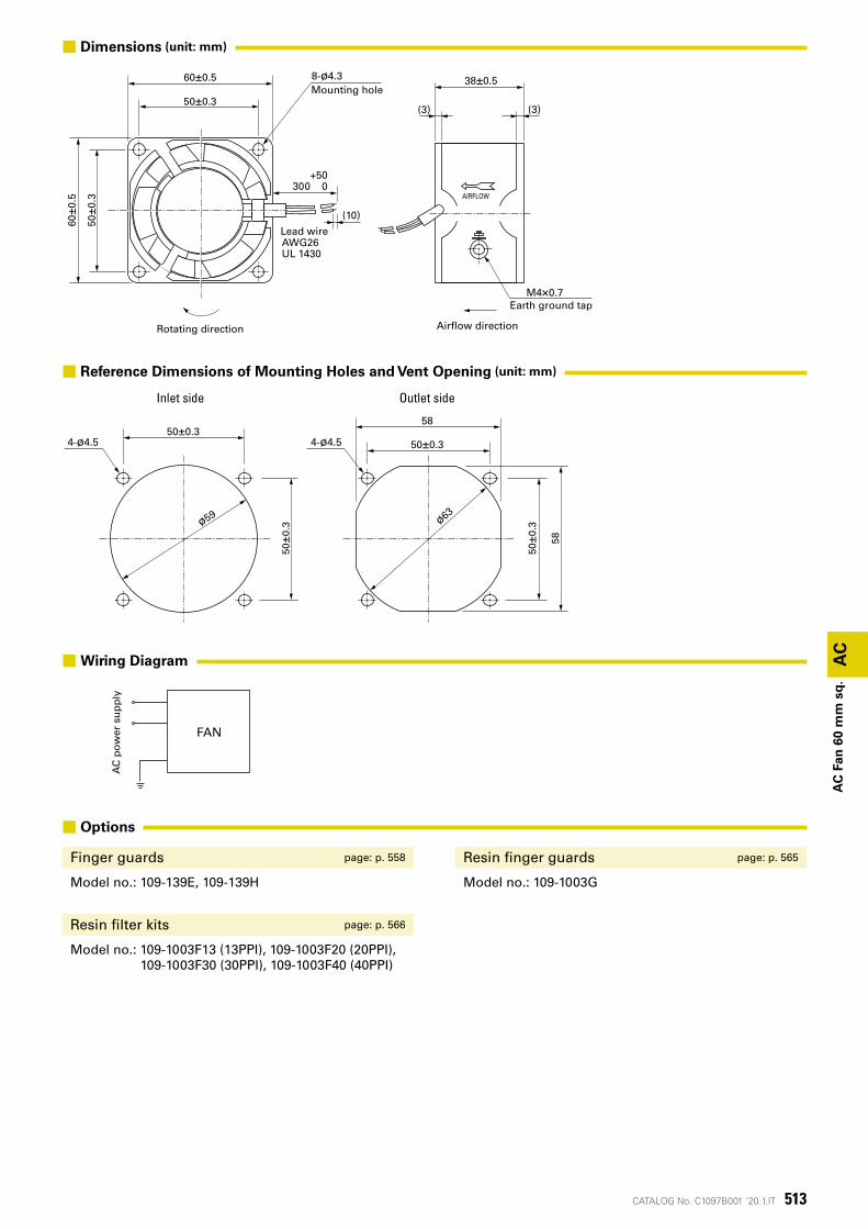
513CATALOG No. C1097B001 '20.1.IT
8-ø4.3
取付用穴
リード線AWG26UL 1430
60±0.5
50±0.3
+50300 0
60±0
.5
50±0
.3
(10)
回転方向
AIRFLOW
38±0.5
(3)
M4×0.7アース用タップ
(3)
風吹出方向
50±0.3
50±0
.3
4-ø4.5 50±0.3
58
50±0
.3
58
4-ø4.5
ø59 ø63
AC電源 ファン
AC
AC
Fan
60
mm
sq
.
Inlet side Outlet side
Lead wire
Mounting hole
Rotating direction Airflow direction
Earth ground tap
■ Dimensions (unit: mm)
■ Reference Dimensions of Mounting Holes and Vent Opening (unit: mm)
■ Options
Finger guards page: p. 558 Resin finger guards page: p. 565
Model no.: 109-139E, 109-139H Model no.: 109-1003G
Resin filter kits page: p. 566
Model no.: 109-1003F13 (13PPI), 109-1003F20 (20PPI), 109-1003F30 (30PPI), 109-1003F40 (40PPI)
AC
po
wer
su
pp
ly
FAN
■Wiring Diagram
514 CATALOG No. C1097B001 '20.1.IT
0.2 0
10
20
30
40
0.4 0.6
0 5 10 15 20
0
0.05
0.10
0.15
(Pa)(inch H2O)
静圧
風量(CFM)
(m3/min)
50 Hz 100 V/115 V
60 Hz 100 V/115 V
109-210, 109-213
AC
AC
Fan
80
mm
sq
.
Sta
tic
pre
ssu
re
Airflow
AC Fan
80×80×20 mmSan Ace 80
■ General Specifications
· Material �������������� Frame: Aluminum, Impeller: Plastic (Flammability: UL 94V-1) · Expected life ������������ See the table below. (L10 life: 90% survival rate for continuous operation in free air at 60˚C, rated voltage)
Expected life at 40°C is for reference only. · Motor structure ���������� Shaded coil motor · Motor protection function ������ Locked rotor burnout protection, Reverse polarity protection
For details, please refer to p. 573. · Dielectric strength ��������� 50/60 Hz, 1500 VAC, for 1 minute (between lead wire conductors and frame) · Insulation resistance �������� 10 MΩ or more with a 500 VDC megger · Sound pressure level (SPL) ����� At 1 m away from the air inlet · Operating voltage range ������ Voltage of each model ±10% · Storage temperature �������� -30 to +70˚C (Non-condensing) · Lead wire ������������� Black, 2 pcs · Mass ��������������� 180 g
■ Specifications
Model no. Rated voltage Frequency Input Current Locked rotor current Rated speed Max. airflow Max. static pressure SPL Operating temperature Expected life[V] [Hz] [W] [A] [A] [min-1] [m³/min] [CFM] [Pa] [inchH²O] [dB (A)] [˚C] [h]
109-210 10050/60 6/5
0.07/0.06 0.07/0.062500/3000 0.44/0.53 15.5/18.7 23.5/31.4 0.094/0.126 26/31 -30 to +60 25000/60˚C
(56000/40˚C)109-213 115 0.06/0.05 0.06/0.05
These are Short Lead Time Service applicable models. Contact your point of sale for stock availability. For more information on the service, see p. 626.
■ Set ModelsFan, finger guard, plug cord, screws, etc. can be purchased in one package. For details, please refer to p. 627.
Order no.Set items
Fan Voltage Low-speed sensor Plug cord Finger guards Mounting screws
ST1-109-210 109-210 100 V Plug cord is not included because of the exposed-lead structure.
109-049EM4×40 mm (4 screws)
ST1-109-213 109-213 115 V 109-049E
■ Airflow - Static Pressure Characteristics
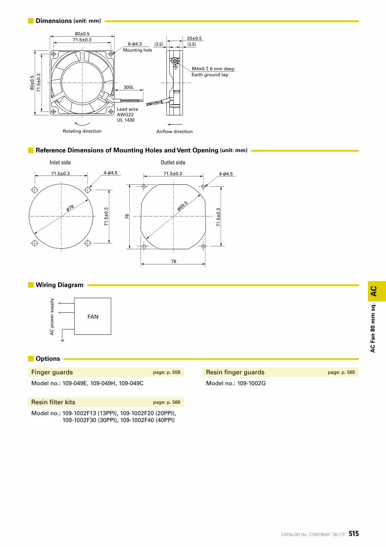
515CATALOG No. C1097B001 '20.1.IT
78
71.5±0.3 4-ø4.5
71.5
±0.3
78
ø89.5
71.5±0.3
71.5
±0.3
4-ø4.5
ø78
リード線AWG22UL 1430
80±0
.571
.5±0
.380±0.5
71.5±0.3(3.5)
300L
(3.5)20±0.5
AIRFLOW
8-ø4.3 取付用穴
アース用タップM4×0.7深6
風吹出方向回転方向
AC電源 ファン
AC
AC
Fan
80
mm
sq
.
Inlet side Outlet side
Rotating direction Airflow direction
Lead wire
M4×0.7, 6 mm deep
Mounting hole
Earth ground tap
■ Dimensions (unit: mm)
■ Reference Dimensions of Mounting Holes and Vent Opening (unit: mm)
■ Options
Finger guards page: p. 558 Resin finger guards page: p. 565
Model no.: 109-049E, 109-049H, 109-049C Model no.: 109-1002G
Resin filter kits page: p. 566
Model no.: 109-1002F13 (13PPI), 109-1002F20 (20PPI), 109-1002F30 (30PPI), 109-1002F40 (40PPI)
AC
po
wer
su
pp
ly
FAN
■Wiring Diagram
516 CATALOG No. C1097B001 '20.1.IT
0
10
20
30
40
0.40.2 0.6 0.8
50
0 5 10 15 20 25 30
0.05
0
0.15
0.10
0.20(Pa)(inch H2O)
静圧
風量(CFM)
(m3/min)
50 Hz 100 V/115 V/200 V/230 V
60 Hz 100 V/115 V/200 V/230 V
0
10
20
30
40
50
0.05
0
0.15
0.10
0.20(Pa)(inch H2O)
静圧
風量(CFM)
(m3/min)0.25 0.50 0.75
0 10 20 30
60 Hz 100 V/115 V/200 V/230 V
50 Hz 100 V/115 V/200 V/230 V
109S050, 109S053, 109S051, 109S054 109S030, 109S033, 109S031, 109S034
AC
AC
Fan
80
mm
sq
.
Sta
tic
pre
ssu
re
Airflow
Sta
tic
pre
ssu
re
Airflow
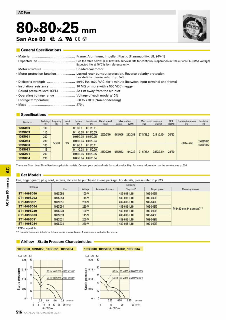
AC Fan
80×80×25 mmSan Ace 80
■ General Specifications
· Material �������������� Frame: Aluminum, Impeller: Plastic (Flammability: UL 94V-1) · Expected life ������������ See the table below. (L10 life: 90% survival rate for continuous operation in free air at 60˚C, rated voltage)
Expected life at 40°C is for reference only. · Motor structure ���������� Shaded coil motor · Motor protection function ������ Locked rotor burnout protection, Reverse polarity protection
For details, please refer to p. 573. · Dielectric strength ��������� 50/60 Hz, 1500 VAC, for 1 minute (between input terminal and frame) · Insulation resistance �������� 10 MΩ or more with a 500 VDC megger · Sound pressure level (SPL) ����� At 1 m away from the air inlet · Operating voltage range ������ Voltage of each model ±10% · Storage temperature �������� -30 to +70˚C (Non-condensing) · Mass ��������������� 270 g
■ Specifications
Model no. Rated voltage Frequency Input Current Locked rotor current Rated speed Max. airflow Max. static pressure SPL Operating temperature Expected life[V] [Hz] [W] [A] [A] [min-1] [m³/min] [CFM] [Pa] [inchH²O] [dB (A)] [˚C] [h]
109S050 100
50/60 9/7
0.12/0.1 0.13/0.11
2650/3100 0.63/0.76 22.3/26.9 27.5/38.3 0.11 /0.154 30/33
-30 to +60 25000/60˚C(56000/40˚C)
109S053 115 0.1 /0.08 0.11/0.09109S051 200 0.06/0.05 0.06/0.05109S054 230 0.05/0.04 0.05/0.04109S030 100 0.12/0.1 0.13/0.11
2350/2700 0.55/0.63 19.4/22.3 21.6/28.4 0.087/0.114 28/30109S033 115 0.1 /0.08 0.11/0.09109S031 200 0.06/0.05 0.06/0.05109S034 230 0.05/0.04 0.05/0.04
These are Short Lead Time Service applicable models. Contact your point of sale for stock availability. For more information on the service, see p. 626.
■ Set ModelsFan, finger guard, plug cord, screws, etc. can be purchased in one package. For details, please refer to p. 627.
Order no.Set items
Fan Voltage Low-speed sensor Plug cord* Finger guards Mounting screws
ST1-109S050 109S050 100 V 489-016-L10 109-049E
M4×40 mm (4 screws)**
ST1-109S053 109S053 115 V 489-016-L10 109-049EST1-109S051 109S051 200 V 489-016-L10 109-049EST1-109S054 109S054 230 V 489-016-L10 109-049EST1-109S030 109S030 100 V 489-016-L10 109-049EST1-109S033 109S033 115 V 489-016-L10 109-049EST1-109S031 109S031 200 V 489-016-L10 109-049EST1-109S034 109S034 230 V 489-016-L10 109-049E
* PSE compatible.
** Though these are 2-hole or 3-hole frame mount types, 4 screws are included for extra.
■ Airflow - Static Pressure Characteristics
517CATALOG No. C1097B001 '20.1.IT
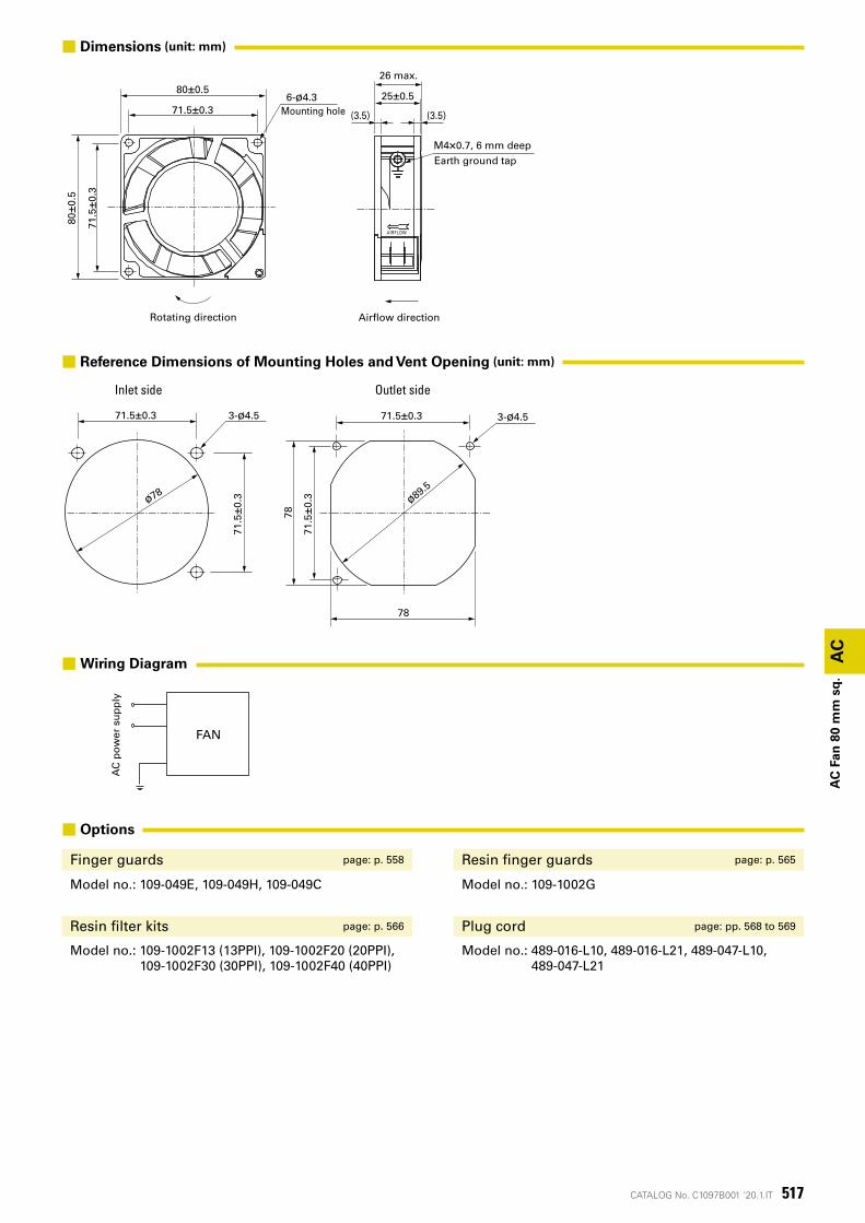
78
3-ø4.571.5±0.3
71.5
±0.3
78
ø89.5
71.5±0.3
71.5
±0.3
3-ø4.5
ø78
25±0.5
26以下
(3.5) (3.5)
80±0.5
71.5±0.3
80±0
.5
71.5
±0.3
AIRFLOW
M4×0.7深6アース用タップ
6-ø4.3取付用穴
風吹出方向回転方向
AC電源 ファン
AC
AC
Fan
80
mm
sq
.
Inlet side Outlet side
Earth ground tap
Mounting hole
Rotating direction Airflow direction
26 max.
M4×0.7, 6 mm deep
■ Options
Finger guards page: p. 558 Resin finger guards page: p. 565
Model no.: 109-049E, 109-049H, 109-049C Model no.: 109-1002G
Resin filter kits page: p. 566 Plug cord page: pp. 568 to 569
Model no.: 109-1002F13 (13PPI), 109-1002F20 (20PPI), 109-1002F30 (30PPI), 109-1002F40 (40PPI)
Model no.: 489-016-L10, 489-016-L21, 489-047-L10, 489-047-L21
■ Dimensions (unit: mm)
■ Reference Dimensions of Mounting Holes and Vent Opening (unit: mm)
AC
po
wer
su
pp
ly
FAN
■Wiring Diagram
518 CATALOG No. C1097B001 '20.1.IT
0.5
10
0
20
50
30
40
1.0 1.5
0.05
0.10
0
0.15
0.20
500 10 20 30 40
(Pa)(inch H2O)
静圧
風量(CFM)
(m3/min)
50 Hz 100 V/115 V/200 V/230 V
60 Hz 100 V/115 V/200 V/230 V
109-150, 109-153, 109-151, 109-154
AC
AC
Fan
80
mm
sq
.
Airflow
Sta
tic
pre
ssu
re
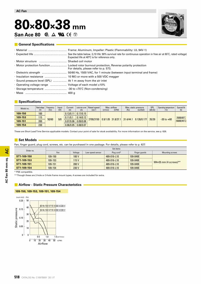
AC Fan
80×80×38 mmSan Ace 80
■ General Specifications
· Material �������������� Frame: Aluminum, Impeller: Plastic (Flammability: UL 94V-1) · Expected life ������������ See the table below. (L10 life: 90% survival rate for continuous operation in free air at 60˚C, rated voltage)
Expected life at 40°C is for reference only. · Motor structure ���������� Shaded coil motor · Motor protection function ������ Locked rotor burnout protection, Reverse polarity protection
For details, please refer to p. 573. · Dielectric strength ��������� 50/60 Hz, 1500 VAC, for 1 minute (between input terminal and frame) · Insulation resistance �������� 10 MΩ or more with a 500 VDC megger · Sound pressure level (SPL) ����� At 1 m away from the air inlet · Operating voltage range ������ Voltage of each model ±10% · Storage temperature �������� -30 to +70˚C (Non-condensing) · Mass ��������������� 400 g
■ Specifications
Model no. Rated voltage Frequency Input Current Locked rotor current Rated speed Max. airflow Max. static pressure SPL Operating temperature Expected life[V] [Hz] [W] [A] [A] [min-1] [m³/min] [CFM] [Pa] [inchH²O] [dB (A)] [˚C] [h]
109-150 100
50/60 9/8
0.13/0.11 0.17/0.15
2700/3150 0.9/1.05 31.8/37.1 31.4/44.1 0.126/0.177 35/39 -30 to +60 25000/60˚C(56000/40˚C)
109-153 115 0.11/0.1 0.14/0.12109-151 200 0.07/0.06 0.09/0.08109-154 230 0.06/0.05 0.08/0.07
These are Short Lead Time Service applicable models. Contact your point of sale for stock availability. For more information on the service, see p. 626.
■ Set ModelsFan, finger guard, plug cord, screws, etc. can be purchased in one package. For details, please refer to p. 627.
Order no.Set items
Fan Voltage Low-speed sensor Plug cord* Finger guards Mounting screws
ST1-109-150 109-150 100 V 489-016-L10 109-049E
M4×55 mm (4 screws)**ST1-109-153 109-153 115 V 489-016-L10 109-049EST1-109-151 109-151 200 V 489-016-L10 109-049EST1-109-154 109-154 230 V 489-016-L10 109-049E
* PSE compatible.
** Though these are 2-hole or 3-hole frame mount types, 4 screws are included for extra.
■ Airflow - Static Pressure Characteristics
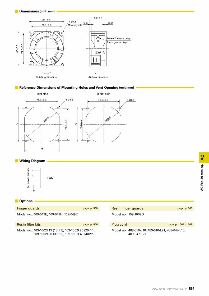
519CATALOG No. C1097B001 '20.1.IT
3-ø4.54-ø4.5 71.5±0.3
71.5
±0.3
78
ø89.5
78
71.5±0.3
71.5
±0.3
78
ø89.5
7-ø4.3取付用穴
80±0.5
71.5±0.3
80±0
.5
71.5
±0.3
(3.5) (3.5)
38±0.5
M4×0.7深6
アース用タップ
AIRFLOW
回転方向 風吹出方向
AC電源 ファン
AC
AC
Fan
80
mm
sq
.
Inlet side Outlet side
Earth ground tap
Mounting hole
Rotating direction Airflow direction
M4×0.7, 6 mm deep
■ Options
Finger guards page: p. 558 Resin finger guards page: p. 565
Model no.: 109-049E, 109-049H, 109-049C Model no.: 109-1002G
Resin filter kits page: p. 566 Plug cord page: pp. 568 to 569
Model no.: 109-1002F13 (13PPI), 109-1002F20 (20PPI), 109-1002F30 (30PPI), 109-1002F40 (40PPI)
Model no.: 489-016-L10, 489-016-L21, 489-047-L10, 489-047-L21
■ Dimensions (unit: mm)
■ Reference Dimensions of Mounting Holes and Vent Opening (unit: mm)
AC
po
wer
su
pp
ly
FAN
■Wiring Diagram
520 CATALOG No. C1097B001 '20.1.IT
40
30
20
10
1.00.80.60.40.2 0
1.2
0 10 20 30 40
0
0.05
0.10
0.15
(Pa)(inch H2O)
静圧
風量(CFM)
(m3/min)
50 Hz 100 V/115 V/200 V/230 V
60 Hz 100 V/115 V/200 V/230 V
(Pa)(inch H2O)
静圧
風量(CFM)
(m3/min) 0
2
4
6
8
10
12
14
16
0.50.40.30.20.1 0.6
0 5 10 15 20
0
0.01
0.02
0.03
0.04
0.05
0.06
50 Hz 100 V/115 V
60 Hz 100 V/115 V
109-040UL, 109-043UL, 109-041UL, 109-044UL
109-047UL, 109-033UL
AC
AC
Fan
80
mm
sq
.
Sta
tic
pre
ssu
re
Airflow
Sta
tic
pre
ssu
re
Airflow
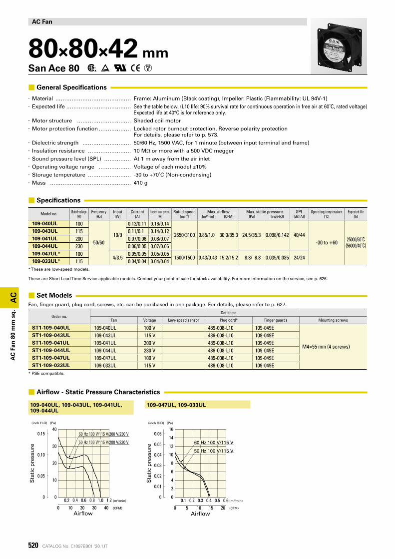
AC Fan
80×80×42 mmSan Ace 80
■ General Specifications
· Material �������������� Frame: Aluminum (Black coating), Impeller: Plastic (Flammability: UL 94V-1) · Expected life ������������ See the table below. (L10 life: 90% survival rate for continuous operation in free air at 60˚C, rated voltage)
Expected life at 40°C is for reference only. · Motor structure ���������� Shaded coil motor · Motor protection function ������ Locked rotor burnout protection, Reverse polarity protection
For details, please refer to p. 573. · Dielectric strength ��������� 50/60 Hz, 1500 VAC, for 1 minute (between input terminal and frame) · Insulation resistance �������� 10 MΩ or more with a 500 VDC megger · Sound pressure level (SPL) ����� At 1 m away from the air inlet · Operating voltage range ������ Voltage of each model ±10% · Storage temperature �������� -30 to +70˚C (Non-condensing) · Mass ��������������� 410 g
■ Specifications
Model no. Rated voltage Frequency Input Current Locked rotor current Rated speed Max. airflow Max. static pressure SPL Operating temperature Expected life[V] [Hz] [W] [A] [A] [min-1] [m³/min] [CFM] [Pa] [inchH²O] [dB (A)] [˚C] [h]
109-040UL 100
50/6010/9
0.13/0.11 0.16/0.14
2650/3100 0.85/1.0 30.0/35.3 24.5/35.3 0.098/0.142 40/44-30 to +60 25000/60˚C
(56000/40˚C)
109-043UL 115 0.11/0.1 0.14/0.12109-041UL 200 0.07/0.06 0.08/0.07109-044UL 230 0.06/0.05 0.07/0.06109-047UL* 100
4/3.50.05/0.05 0.05/0.05
1500/1500 0.43/0.43 15.2/15.2 8.8/ 8.8 0.035/0.035 24/24109-033UL* 115 0.04/0.04 0.04/0.04
* These are low-speed models.
These are Short Lead Time Service applicable models. Contact your point of sale for stock availability. For more information on the service, see p. 626.
■ Set ModelsFan, finger guard, plug cord, screws, etc. can be purchased in one package. For details, please refer to p. 627.
Order no.Set items
Fan Voltage Low-speed sensor Plug cord* Finger guards Mounting screws
ST1-109-040UL 109-040UL 100 V 489-008-L10 109-049E
M4×55 mm (4 screws)
ST1-109-043UL 109-043UL 115 V 489-008-L10 109-049EST1-109-041UL 109-041UL 200 V 489-008-L10 109-049EST1-109-044UL 109-044UL 230 V 489-008-L10 109-049EST1-109-047UL 109-047UL 100 V 489-008-L10 109-049EST1-109-033UL 109-033UL 115 V 489-008-L10 109-049E
* PSE compatible.
■ Airflow - Static Pressure Characteristics
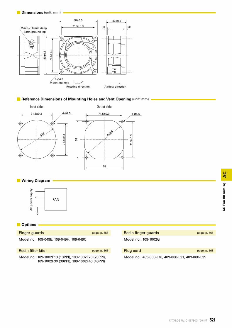
521CATALOG No. C1097B001 '20.1.IT
78
71.5±0.3 4-ø4.5
71.5
±0.3
78
ø89.5
71.5±0.3
71.5
±0.3
4-ø4.5
ø78
42±0.5
(3) (3)
80±0.5
71.5±0.3
8-ø4.3
取付用穴
80±0
.5
71.5
±0.3
M4×0.7深6アース用タップ
風吹出方向回転方向
AC電源 ファン
AC
AC
Fan
80
mm
sq
.
Outlet sideInlet side
Rotating direction Airflow directionMounting hole
Earth ground tapM4×0.7, 6 mm deep
■ Options
Finger guards page: p. 558 Resin finger guards page: p. 565
Model no.: 109-049E, 109-049H, 109-049C Model no.: 109-1002G
Resin filter kits page: p. 566 Plug cord page: p. 568
Model no.: 109-1002F13 (13PPI), 109-1002F20 (20PPI), 109-1002F30 (30PPI), 109-1002F40 (40PPI)
Model no.: 489-008-L10, 489-008-L21, 489-008-L35
■ Dimensions (unit: mm)
■ Reference Dimensions of Mounting Holes and Vent Opening (unit: mm)
AC
po
wer
su
pp
ly
FAN
■Wiring Diagram
522 CATALOG No. C1097B001 '20.1.IT
AC
AC
Fan
92
mm
sq
.
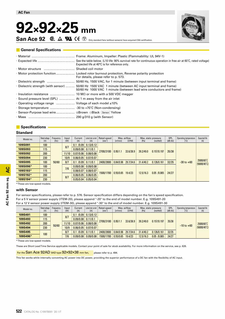
AC Fan
92×92×25 mmSan Ace 92 Only standard fans (without sensors) have acquired CSA certification.
■ General Specifications
· Material �������������� Frame: Aluminum, Impeller: Plastic (Flammability: UL 94V-1) · Expected life ������������ See the table below. (L10 life: 90% survival rate for continuous operation in free air at 60˚C, rated voltage)
Expected life at 40°C is for reference only. · Motor structure ���������� Shaded coil motor · Motor protection function ������ Locked rotor burnout protection, Reverse polarity protection
For details, please refer to p. 573. · Dielectric strength ��������� 50/60 Hz, 1500 VAC, for 1 minute (between input terminal and frame) · Dielectric strength (with sensor) ��� 50/60 Hz 1500 VAC 1 minute (between AC input terminal and frame)
50/60 Hz 1000 VAC 1 minute (between lead wire conductors and frame) · Insulation resistance �������� 10 MΩ or more with a 500 VDC megger · Sound pressure level (SPL) ����� At 1 m away from the air inlet · Operating voltage range ������ Voltage of each model ±10% · Storage temperature �������� -30 to +70˚C (Non-condensing) · Sensor-Purpose lead wire ������ Brown Black Sensor Yellow · Mass ��������������� 290 g/310 g (with Sensor)
■ Specifications
Standard
Model no. Rated voltage Frequency Input Current Locked rotor current Rated speed Max. airflow Max. static pressure SPL Operating temperature Expected life[V] [Hz] [W] [A] [A] [min-1] [m³/min] [CFM] [Pa] [inchH²O] [dB (A)] [˚C] [h]
109S091 100
50/60
8/70.1 /0.09 0.13/0.12
2700/3100 0.95/1.1 33.6/38.9 39.2/49.0 0.157/0.197 35/38
-30 to +60 25000/60˚C(56000/40˚C)
109S093 115 0.09/0.08 0.11/0.1109S092 200 11/10 0.07/0.06 0.08/0.08109S094 230 10/9 0.06/0.05 0.07/0.07109S095 100 8/7 0.1 /0.09 0.11/0.1 2400/2800 0.84/0.98 29.7/34.6 31.4/40.2 0.126/0.161 32/35109S096* 100
7/60.09/0.08 0.09/0.08
1500/1700 0.55/0.65 19.4/23 12.5/16.3 0.05 /0.065 24/27109S193* 115 0.08/0.07 0.08/0.07109S192* 200
8/70.06/0.05 0.06/0.05
109S194* 230 0.05/0.04 0.05/0.04* These are low-speed models.
with SensorFor sensor specifications, please refer to p. 576. Sensor specification differs depending on the fan's speed specification.For a 5 V sensor power supply (ITEM-20), please append "-20" to the end of model number. E.g. 109S491-20For a 12 V sensor power supply (ITEM-30), please append "-30" to the end of model number. E.g. 109S491-30
Model no. Rated voltage Frequency Input Current Locked rotor current Rated speed Max. airflow Max. static pressure SPL Operating temperature Expected life[V] [Hz] [W] [A] [A] [min-1] [m³/min] [CFM] [Pa] [inchH²O] [dB (A)] [˚C] [h]
109S491 100
50/60
8/70.1 /0.09 0.13/0.12
2700/3100 0.95/1.1 33.6/38.9 39.2/49.0 0.157/0.197 35/38-10 to +60 25000/60˚C
(56000/40˚C)
109S493 115 0.09/0.08 0.11/0.1109S492 200 11/10 0.07/0.06 0.08/0.08109S494 230 10/9 0.06/0.05 0.07/0.07109S495
1008/7 0.1 /0.09 0.11/0.1 2400/2800 0.84/0.98 29.7/34.6 31.4/40.2 0.126/0.161 32/35
109S496* 7/6 0.09/0.08 0.09/0.08 1500/1700 0.55/0.65 19.4/23 12.5/16.3 0.05 /0.065 24/27* These are low-speed models.
These are Short Lead Time Service applicable models. Contact your point of sale for stock availability. For more information on the service, see p. 626.
For the San Ace 92AD 9AD type 92×92×38 mm fan, please refer to p. 494.
This fan works while internally converting AC power into DC power, providing the superior performance of a DC fan with the flexibility of AC input.
523CATALOG No. C1097B001 '20.1.IT
10
0
20
50
30
40
60
0.05
0
0.20
0.15
0.10
0.25
0.5 1.0 1.5
500 10 20 30 40
(Pa)(inch H2O)
静圧
風量(CFM)
(m3/min)
60 Hz 100 V/115 V/200 V/230 V
50 Hz 100 V/115 V/200 V/230 V
0.5
10
0
20
50
30
40
1.0 1.5 0
0.05
0.10
0.15
0.20
500 10 20 30 40
(Pa)(inch H2O)
静圧
風量(CFM)
(m3/min)
50 Hz 100 V
60 Hz 100 V
0
10
20
1.00.5
30
0
0.05
0.10
0 2010 30
(Pa)(inch H2O)
静圧
風量(CFM)
(m3/min)
50 Hz 100 V/115 V/200 V/230 V
60 Hz 100 V/115 V/200 V/230 V
10
0
20
50
30
40
60
0.05
0
0.20
0.15
0.10
0.25
0.5 1.0 1.5
500 10 20 30 40
(Pa)(inch H2O)
静圧
風量(CFM)
(m3/min)
60 Hz 100 V/115 V/200 V/230 V
50 Hz 100 V/115 V/200 V/230 V
0.5
10
0
20
50
30
40
1.0 1.5
0.05
0.10
0
0.15
0.20
500 10 20 30 40
(Pa)(inch H2O)
静圧
風量(CFM)
(m3/min)
50 Hz 100 V
60 Hz 100 V
0
10
20
1.00.5
30
0
0.05
0.10
0 2010 30
(Pa)(inch H2O)
静圧
風量(CFM)
(m3/min)
50 Hz 100 V
60 Hz 100 V
109S091, 109S093, 109S092, 109S094
109S491, 109S493, 109S492, 109S494
109S095
109S495
109S096, 109S193, 109S192, 109S194
109S496
AC
AC
Fan
92
mm
sq
.
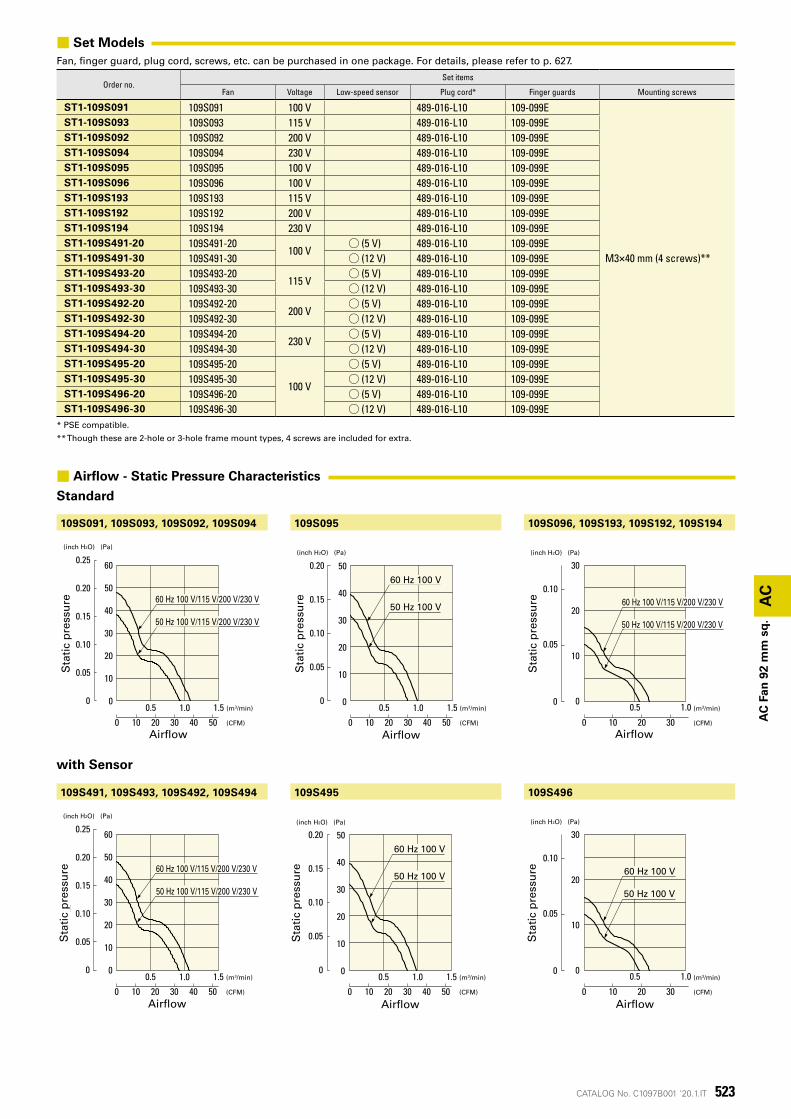
■ Set ModelsFan, finger guard, plug cord, screws, etc. can be purchased in one package. For details, please refer to p. 627.
Order no.Set items
Fan Voltage Low-speed sensor Plug cord* Finger guards Mounting screws
ST1-109S091 109S091 100 V 489-016-L10 109-099E
M3×40 mm (4 screws)**
ST1-109S093 109S093 115 V 489-016-L10 109-099EST1-109S092 109S092 200 V 489-016-L10 109-099EST1-109S094 109S094 230 V 489-016-L10 109-099EST1-109S095 109S095 100 V 489-016-L10 109-099EST1-109S096 109S096 100 V 489-016-L10 109-099EST1-109S193 109S193 115 V 489-016-L10 109-099EST1-109S192 109S192 200 V 489-016-L10 109-099EST1-109S194 109S194 230 V 489-016-L10 109-099EST1-109S491-20 109S491-20
100 V◯ (5 V) 489-016-L10 109-099E
ST1-109S491-30 109S491-30 ◯ (12 V) 489-016-L10 109-099EST1-109S493-20 109S493-20
115 V◯ (5 V) 489-016-L10 109-099E
ST1-109S493-30 109S493-30 ◯ (12 V) 489-016-L10 109-099EST1-109S492-20 109S492-20
200 V◯ (5 V) 489-016-L10 109-099E
ST1-109S492-30 109S492-30 ◯ (12 V) 489-016-L10 109-099EST1-109S494-20 109S494-20
230 V◯ (5 V) 489-016-L10 109-099E
ST1-109S494-30 109S494-30 ◯ (12 V) 489-016-L10 109-099EST1-109S495-20 109S495-20
100 V
◯ (5 V) 489-016-L10 109-099EST1-109S495-30 109S495-30 ◯ (12 V) 489-016-L10 109-099EST1-109S496-20 109S496-20 ◯ (5 V) 489-016-L10 109-099EST1-109S496-30 109S496-30 ◯ (12 V) 489-016-L10 109-099E
* PSE compatible.
** Though these are 2-hole or 3-hole frame mount types, 4 screws are included for extra.
with Sensor
Sta
tic
pre
ssu
re
Sta
tic
pre
ssu
re
Sta
tic
pre
ssu
re
AirflowAirflowAirflow
Sta
tic
pre
ssu
re
Sta
tic
pre
ssu
re
Sta
tic
pre
ssu
re
AirflowAirflowAirflow
■ Airflow - Static Pressure Characteristics
Standard
524 CATALOG No. C1097B001 '20.1.IT
82.5±0.3
82.5
±0.3
3-ø4
ø90
92±0.5
92±0
.5
46
721.
5 1.5
116.6
±0.5
4-ø3.7取付用穴
AIR-FLOW
25±0.5
26以下
(3.5) (3.5)
M4×0.7深6アース用タップ
風吹出方向
センサ用リード線長さ300LAWG28UL 1007
回転方向
116.6
±0.3
2-ø4
ø90
M4×0.7深6アース用タップ
AIR-FLOW
6-ø3.7取付用穴
25±0.5
26以下
(3.5) (3.5)92±0.582.5±0.3
92±0
.5
82.5
±0.3
回転方向 風吹出方向
AC
AC
Fan
92
mm
sq
.
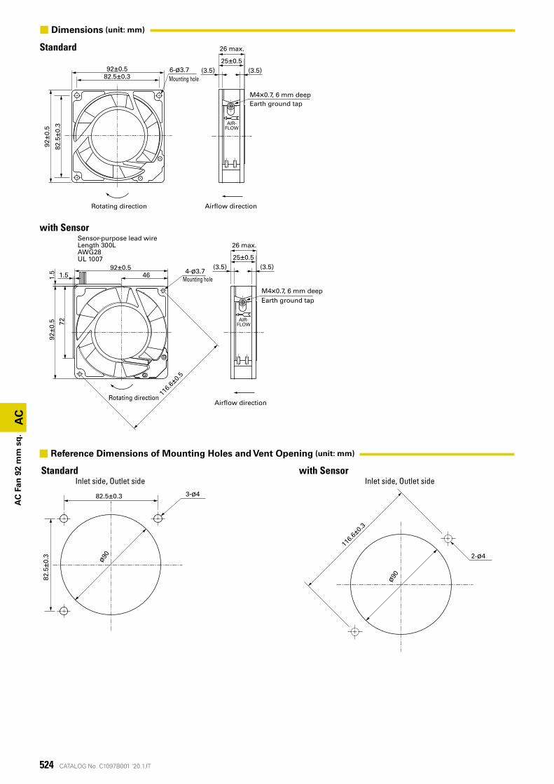
Standard
Standard
with Sensor
with SensorInlet side, Outlet side Inlet side, Outlet side
Mounting hole
26 max.
26 max.
Rotating direction
Rotating direction
Airflow direction
Airflow direction
Mounting hole
Earth ground tap
Earth ground tap
Sensor-purpose lead wireLength 300LAWG28UL 1007
M4×0.7, 6 mm deep
M4×0.7, 6 mm deep
■ Dimensions (unit: mm)
■ Reference Dimensions of Mounting Holes and Vent Opening (unit: mm)
525CATALOG No. C1097B001 '20.1.IT
AC電源 ファン
AC電源 ファン
AC
AC
Fan
92
mm
sq
.
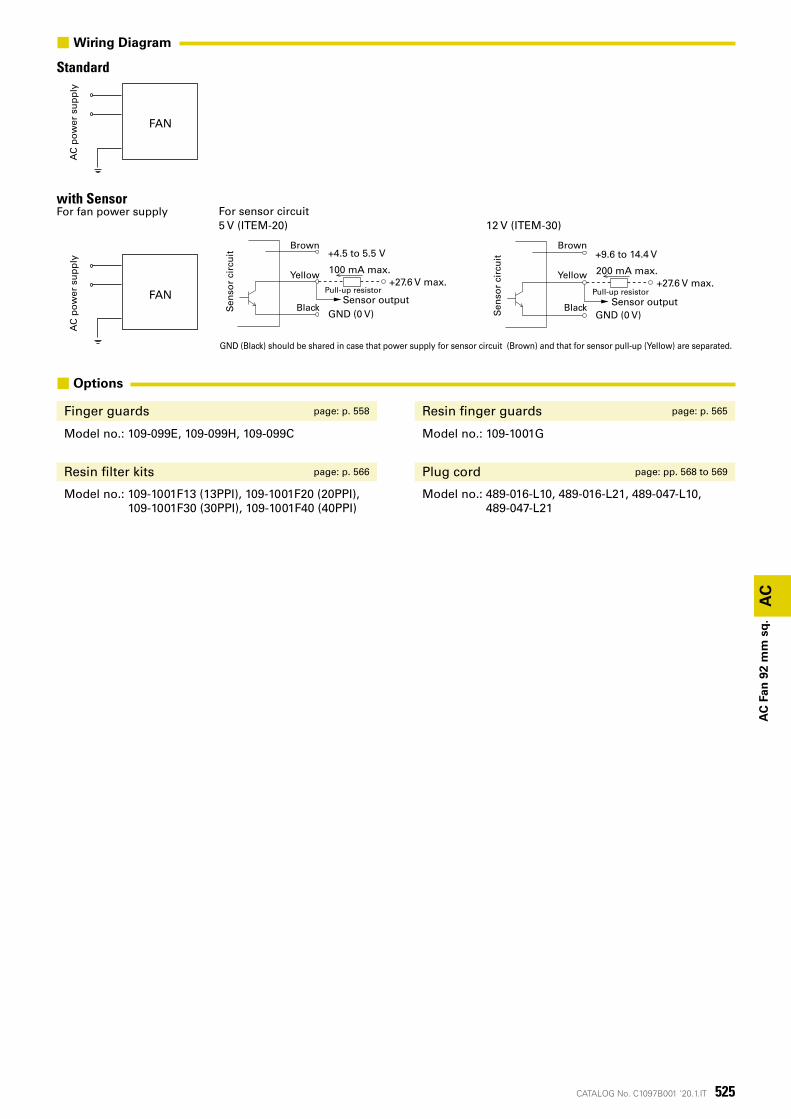
■ Options
Finger guards page: p. 558 Resin finger guards page: p. 565
Model no.: 109-099E, 109-099H, 109-099C Model no.: 109-1001G
Resin filter kits page: p. 566 Plug cord page: pp. 568 to 569
Model no.: 109-1001F13 (13PPI), 109-1001F20 (20PPI), 109-1001F30 (30PPI), 109-1001F40 (40PPI)
Model no.: 489-016-L10, 489-016-L21, 489-047-L10, 489-047-L21
with SensorFor fan power supply
StandardA
C p
ow
er s
up
ply
AC
po
wer
su
pp
ly
Sen
sor
circ
uit
Brown
Yellow
Black
Pull-up resistor
+4.5 to 5.5 V
GND (0 V)
+27.6 V max.100 mA max.
Sensor output
Sen
sor
circ
uit
Brown
Yellow
Black
Pull-up resistor
+9.6 to 14.4 V
GND (0 V)
+27.6 V max.200 mA max.
Sensor output
For sensor circuit5 V (ITEM-20) 12 V (ITEM-30)
GND (Black) should be shared in case that power supply for sensor circuit (Brown) and that for sensor pull-up (Yellow) are separated.
FAN
FAN
■Wiring Diagram
526 CATALOG No. C1097B001 '20.1.IT
AC
AC
Fan
120
mm
sq
.
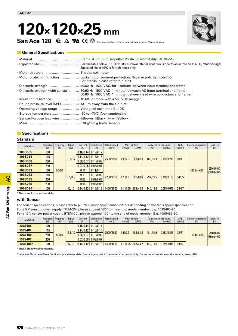
AC Fan
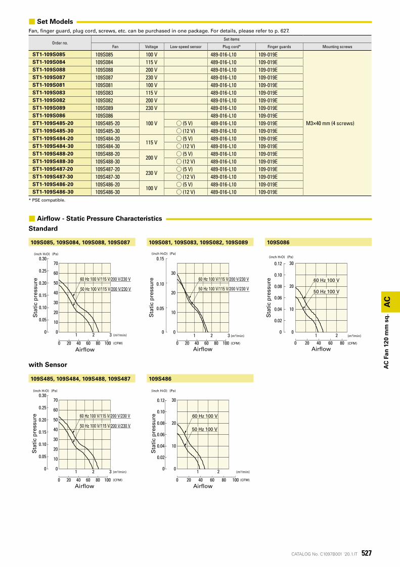
120×120×25 mmSan Ace 120 Only standard fans (without sensors) have acquired CSA certification.
■ General Specifications
· Material �������������� Frame: Aluminum, Impeller: Plastic (Flammability: UL 94V-1) · Expected life ������������ See the table below. (L10 life: 90% survival rate for continuous operation in free air at 60˚C, rated voltage)
Expected life at 40°C is for reference only. · Motor structure ���������� Shaded coil motor · Motor protection function ������ Locked rotor burnout protection, Reverse polarity protection
For details, please refer to p. 573. · Dielectric strength ��������� 50/60 Hz, 1500 VAC, for 1 minute (between input terminal and frame) · Dielectric strength (with sensor) ��� 50/60 Hz 1500 VAC 1 minute (between AC input terminal and frame)
50/60 Hz 1000 VAC 1 minute (between lead wire conductors and frame) · Insulation resistance �������� 10 MΩ or more with a 500 VDC megger · Sound pressure level (SPL) ����� At 1 m away from the air inlet · Operating voltage range ������ Voltage of each model ±10% · Storage temperature �������� -30 to +70˚C (Non-condensing) · Sensor-Purpose lead wire ������ Brown Black Sensor Yellow · Mass ��������������� 370 g/390 g (with Sensor)
■ Specifications
Standard
Model no. Rated voltage Frequency Input Current Locked rotor current Rated speed Max. airflow Max. static pressure SPL Operating temperature Expected life[V] [Hz] [W] [A] [A] [min-1] [m³/min] [CFM] [Pa] [inchH²O] [dB (A)] [˚C] [h]
109S085 100
50/60
13.5/12
0.16/0.14 0.19/0.17
2500/2900 1.95/2.3 68.9/81.3 48 /51.9 0.193/0.216 38/41
-30 to +60 25000/60˚C(56000/40˚C)
109S084 115 0.14/0.12 0.16/0.15109S088 200 0.08/0.07 0.1 /0.09109S087 230 0.07/0.06 0.08/0.07109S081 100
9.5/8.5
0.11 0.11/0.1
2200/2350 1.7 /1.8 60.1/63.6 29.4/26.5 0.118/0.106 34/35109S083 115 0.1 0.1 /0.09109S082 200 0.07 0.07/0.06109S089 230 0.06 0.06/0.05109S086* 100 12/10 0.14/0.12 0.15/0.13 1400/1600 1.1 /1.25 38.9/44.2 14.7/18.6 0.059/0.075 24/27
* These are low-speed models.
with SensorFor sensor specifications, please refer to p. 576. Sensor specification differs depending on the fan's speed specification.For a 5 V sensor power supply (ITEM-20), please append "-20" to the end of model number. E.g. 109S485-20For a 12 V sensor power supply (ITEM-30), please append "-30" to the end of model number. E.g. 109S485-30
Model no. Rated voltage Frequency Input Current Locked rotor current Rated speed Max. airflow Max. static pressure SPL Operating temperature Expected life[V] [Hz] [W] [A] [A] [min-1] [m³/min] [CFM] [Pa] [inchH²O] [dB (A)] [˚C] [h]
109S485 100
50/6013.5/12
0.16/0.14 0.19/0.17
2500/2900 1.95/2.3 68.9/81.3 48 /51.9 0.193/0.216 38/41-10 to +60 25000/60˚C
(56000/40˚C)
109S484 115 0.14/0.12 0.16/0.15109S488 200 0.08/0.07 0.1 /0.09109S487 230 0.07/0.06 0.08/0.07109S486* 100 12/10 0.14/0.12 0.15/0.13 1400/1600 1.1 /1.25 38.9/44.2 14.7/18.6 0.059/0.075 24/27
* These are low-speed models.
These are Short Lead Time Service applicable models. Contact your point of sale for stock availability. For more information on the service, see p. 626.
527CATALOG No. C1097B001 '20.1.IT
(Pa)(inch H2O)
1 2 3
0.30
0.25
0.20
0.15
0.10
0.05
0
70
60
50
40
30
20
10
0
静圧
0 20 40 8060 100 (CFM)
(m3/min)
風量
60 Hz 100 V/115 V/200 V/230 V
50 Hz 100 V/115 V/200 V/230 V
30
20
10
021 3
0 20 40 60 80
0
0.05
0.10
0.15
100
(Pa)(inch H2O)
静圧
風量(CFM)
(m3/min)
60 Hz 100 V/115 V/200 V/230 V
50 Hz 100 V/115 V/200 V/230 V
(Pa)(inch H2O)
静圧
風量(CFM)
(m3/min)
30
20
10
21 0 0
0.10
0.06
0.04
0.02
0.08
0.12
0 80604020
60 Hz 100 V
50 Hz 100 V
(Pa)(inch H2O)
1 2 3
0.30
0.25
0.20
0.15
0.10
0.05
0
70
60
50
40
30
20
10
0
静圧
0 20 40 8060 100 (CFM)
(m3/min)
風量
60 Hz 100 V/115 V/200 V/230 V
50 Hz 100 V/115 V/200 V/230 V
(Pa)(inch H2O)
1 2
0.12
0.10
0.08
0.06
0.04
0.02
0
30
20
10
0
静圧
0 20 40 8060 100 (CFM)
(m3/min)
風量
60 Hz 100 V
50 Hz 100 V
109S085, 109S084, 109S088, 109S087
109S485, 109S484, 109S488, 109S487
109S081, 109S083, 109S082, 109S089
109S486
109S086
AC
AC
Fan
120
mm
sq
.
■ Set ModelsFan, finger guard, plug cord, screws, etc. can be purchased in one package. For details, please refer to p. 627.
Order no.Set items
Fan Voltage Low-speed sensor Plug cord* Finger guards Mounting screws
ST1-109S085 109S085 100 V 489-016-L10 109-019E
M3×40 mm (4 screws)
ST1-109S084 109S084 115 V 489-016-L10 109-019EST1-109S088 109S088 200 V 489-016-L10 109-019EST1-109S087 109S087 230 V 489-016-L10 109-019EST1-109S081 109S081 100 V 489-016-L10 109-019EST1-109S083 109S083 115 V 489-016-L10 109-019EST1-109S082 109S082 200 V 489-016-L10 109-019EST1-109S089 109S089 230 V 489-016-L10 109-019EST1-109S086 109S086
100 V489-016-L10 109-019E
ST1-109S485-20 109S485-20 ◯ (5 V) 489-016-L10 109-019EST1-109S485-30 109S485-30 ◯ (12 V) 489-016-L10 109-019EST1-109S484-20 109S484-20
115 V◯ (5 V) 489-016-L10 109-019E
ST1-109S484-30 109S484-30 ◯ (12 V) 489-016-L10 109-019EST1-109S488-20 109S488-20
200 V◯ (5 V) 489-016-L10 109-019E
ST1-109S488-30 109S488-30 ◯ (12 V) 489-016-L10 109-019EST1-109S487-20 109S487-20
230 V◯ (5 V) 489-016-L10 109-019E
ST1-109S487-30 109S487-30 ◯ (12 V) 489-016-L10 109-019EST1-109S486-20 109S486-20
100 V◯ (5 V) 489-016-L10 109-019E
ST1-109S486-30 109S486-30 ◯ (12 V) 489-016-L10 109-019E* PSE compatible.
Sta
tic
pre
ssu
reS
tati
c p
ress
ure
Sta
tic
pre
ssu
reS
tati
c p
ress
ure
Sta
tic
pre
ssu
re
Airflow Airflow Airflow
Airflow Airflow
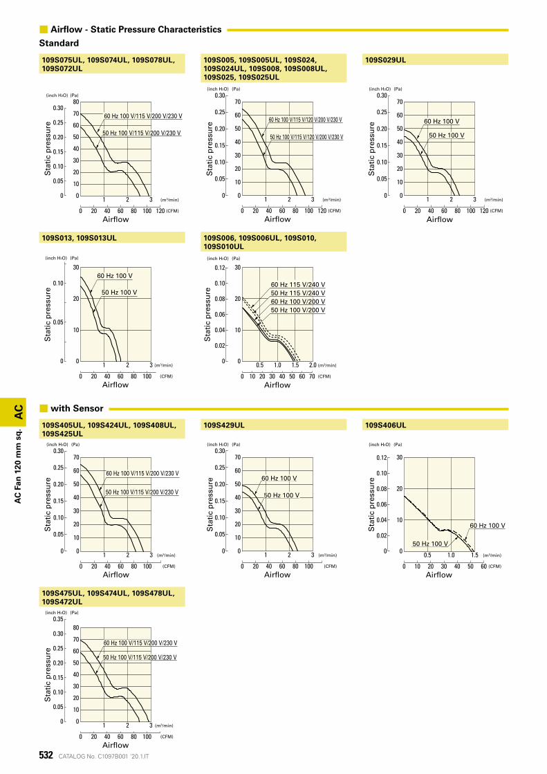
with Sensor
■ Airflow - Static Pressure Characteristics
Standard
528 CATALOG No. C1097B001 '20.1.IT
119±0.5
104.8±0.5
回転方向 風吹出方向
104.
8±0.
511
9±0.
5
M4×0.7深6アース用タップ
3.5 3.525±0.5
26以下
8-ø3.7取付用穴
119±0.5
104.8±0.3
回転方向 風吹出方向
M4×0.7深6アース用タップ
3.5 3.525.3±0.526 以下
1.541
センサ用リード線長さ300LAWG28UL 1007
799.
5
119±
0.5
104.
8±0.
3
9.5
1.58-ø3.7取付用穴
104.8±0.3
104.
8±0.
3
104.8±0.3
115
104.
8±0.
3
115
4-ø44-ø4
ø117
ø127
AC
AC
Fan
120
mm
sq
.
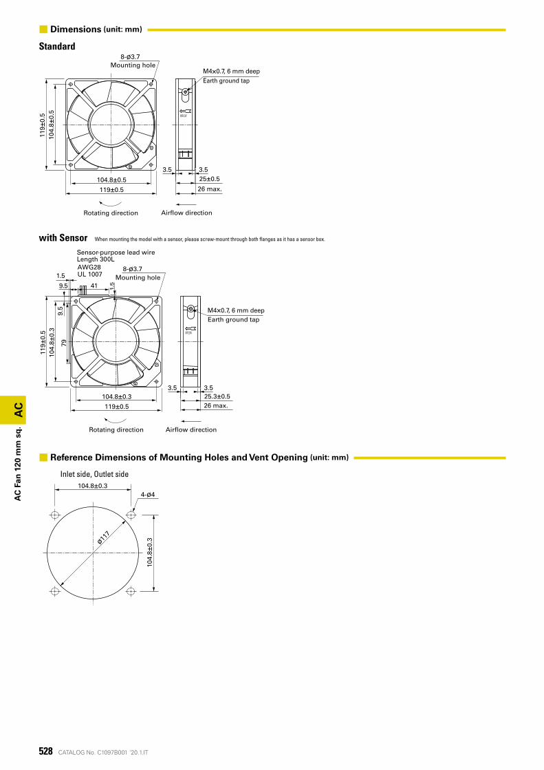
Standard
Inlet side, Outlet side
with Sensor
Rotating direction Airflow direction
Earth ground tap
Rotating direction Airflow direction
Earth ground tapM4×0.7, 6 mm deep
M4×0.7, 6 mm deep
Sensor-purpose lead wireLength 300L
26 max.
26 max.
Mounting hole
Mounting hole
When mounting the model with a sensor, please screw-mount through both flanges as it has a sensor box.
■ Dimensions (unit: mm)
■ Reference Dimensions of Mounting Holes and Vent Opening (unit: mm)
529CATALOG No. C1097B001 '20.1.IT
AC電源 ファン
AC電源 ファン
AC
AC
Fan
120
mm
sq
.
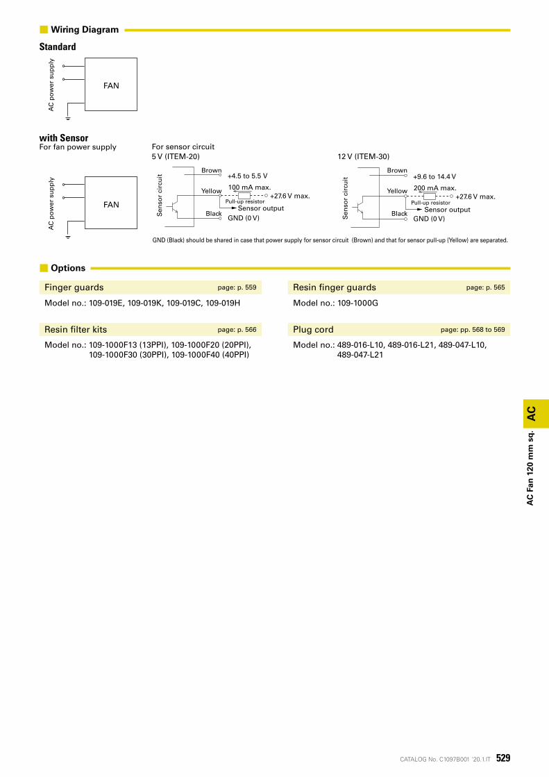
■ Options
Finger guards page: p. 559 Resin finger guards page: p. 565
Model no.: 109-019E, 109-019K, 109-019C, 109-019H Model no.: 109-1000G
Resin filter kits page: p. 566 Plug cord page: pp. 568 to 569
Model no.: 109-1000F13 (13PPI), 109-1000F20 (20PPI), 109-1000F30 (30PPI), 109-1000F40 (40PPI)
Model no.: 489-016-L10, 489-016-L21, 489-047-L10, 489-047-L21
StandardA
C p
ow
er s
up
ply
FAN
■Wiring Diagram
with SensorFor fan power supply
AC
po
wer
su
pp
ly
Sen
sor
circ
uit
Brown
Yellow
Black
Pull-up resistor
+4.5 to 5.5 V
GND (0 V)
+27.6 V max.100 mA max.
Sensor output
Sen
sor
circ
uit
Brown
Yellow
Black
Pull-up resistor
+9.6 to 14.4 V
GND (0 V)
+27.6 V max.200 mA max.
Sensor output
For sensor circuit5 V (ITEM-20) 12 V (ITEM-30)
GND (Black) should be shared in case that power supply for sensor circuit (Brown) and that for sensor pull-up (Yellow) are separated.
FAN
530 CATALOG No. C1097B001 '20.1.IT
AC
AC
Fan
120
mm
sq
.
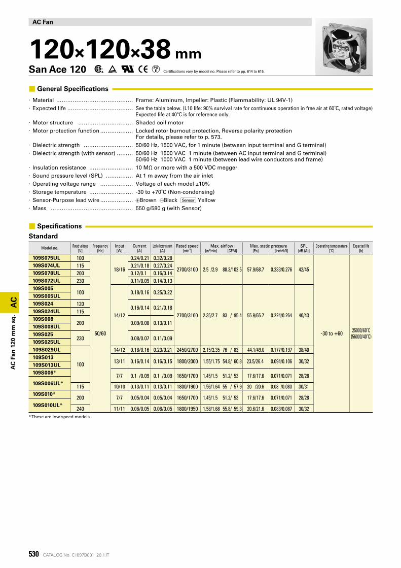
AC Fan
120×120×38 mmSan Ace 120 Certifications vary by model no. Please refer to pp. 614 to 615.
■ General Specifications
· Material �������������� Frame: Aluminum, Impeller: Plastic (Flammability: UL 94V-1) · Expected life ������������ See the table below. (L10 life: 90% survival rate for continuous operation in free air at 60˚C, rated voltage)
Expected life at 40°C is for reference only. · Motor structure ���������� Shaded coil motor · Motor protection function ������ Locked rotor burnout protection, Reverse polarity protection
For details, please refer to p. 573. · Dielectric strength ��������� 50/60 Hz, 1500 VAC, for 1 minute (between input terminal and G terminal) · Dielectric strength (with sensor) ��� 50/60 Hz 1500 VAC 1 minute (between AC input terminal and G terminal)
50/60 Hz 1000 VAC 1 minute (between lead wire conductors and frame) · Insulation resistance �������� 10 MΩ or more with a 500 VDC megger · Sound pressure level (SPL) ����� At 1 m away from the air inlet · Operating voltage range ������ Voltage of each model ±10% · Storage temperature �������� -30 to +70˚C (Non-condensing) · Sensor-Purpose lead wire ������ Brown Black Sensor Yellow · Mass ��������������� 550 g/580 g (with Sensor)
■ Specifications
Standard
Model no. Rated voltage Frequency Input Current Locked rotor current Rated speed Max. airflow Max. static pressure SPL Operating temperature Expected life[V] [Hz] [W] [A] [A] [min-1] [m³/min] [CFM] [Pa] [inchH²O] [dB (A)] [˚C] [h]
109S075UL 100
50/60
18/16
0.24/0.21 0.32/0.28
2700/3100 2.5 /2.9 88.3/102.5 57.9/68.7 0.233/0.276 42/45
-30 to +60 25000/60˚C(56000/40˚C)
109S074UL 115 0.21/0.18 0.27/0.24109S078UL 200 0.12/0.1 0.16/0.14109S072UL 230 0.11/0.09 0.14/0.13109S005
100
14/12
0.18/0.16 0.25/0.22
2700/3100 2.35/2.7 83 / 95.4 55.9/65.7 0.224/0.264 40/43
109S005UL109S024 120
0.16/0.14 0.21/0.18109S024UL 115109S008
200 0.09/0.08 0.13/0.11109S008UL109S025
230 0.08/0.07 0.11/0.09109S025UL109S029UL
100
14/12 0.18/0.16 0.23/0.21 2450/2700 2.15/2.35 76 / 83 44.1/49.0 0.177/0.197 38/40109S013
13/11 0.16/0.14 0.16/0.15 1800/2000 1.55/1.75 54.8/ 60.8 23.5/26.4 0.094/0.106 30/32109S013UL109S006* 7/7 0.1 /0.09 0.1 /0.09 1650/1700 1.45/1.5 51.2/ 53 17.6/17.6 0.071/0.071 28/28109S006UL* 115 10/10 0.13/0.11 0.13/0.11 1800/1900 1.56/1.64 55 / 57.9 20 /20.6 0.08 /0.083 30/31109S010*
200 7/7 0.05/0.04 0.05/0.04 1650/1700 1.45/1.5 51.2/ 53 17.6/17.6 0.071/0.071 28/28109S010UL*
240 11/11 0.06/0.05 0.06/0.05 1800/1950 1.58/1.68 55.8/ 59.3 20.6/21.6 0.083/0.087 30/32* These are low-speed models.
531CATALOG No. C1097B001 '20.1.IT
AC
AC
Fan
120
mm
sq
.
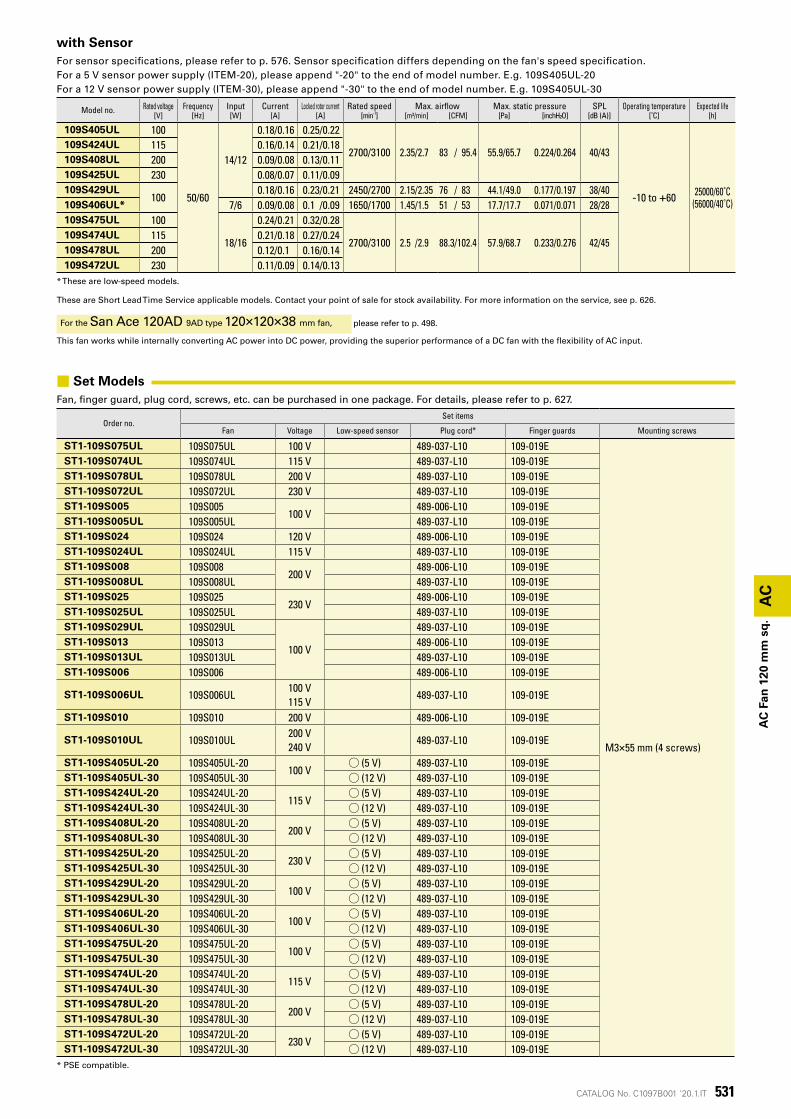
with SensorFor sensor specifications, please refer to p. 576. Sensor specification differs depending on the fan's speed specification.For a 5 V sensor power supply (ITEM-20), please append "-20" to the end of model number. E.g. 109S405UL-20For a 12 V sensor power supply (ITEM-30), please append "-30" to the end of model number. E.g. 109S405UL-30
Model no. Rated voltage Frequency Input Current Locked rotor current Rated speed Max. airflow Max. static pressure SPL Operating temperature Expected life[V] [Hz] [W] [A] [A] [min-1] [m³/min] [CFM] [Pa] [inchH²O] [dB (A)] [˚C] [h]
109S405UL 100
50/60
14/12
0.18/0.16 0.25/0.22
2700/3100 2.35/2.7 83 / 95.4 55.9/65.7 0.224/0.264 40/43
-10 to +60 25000/60˚C(56000/40˚C)
109S424UL 115 0.16/0.14 0.21/0.18109S408UL 200 0.09/0.08 0.13/0.11109S425UL 230 0.08/0.07 0.11/0.09109S429UL
1000.18/0.16 0.23/0.21 2450/2700 2.15/2.35 76 / 83 44.1/49.0 0.177/0.197 38/40
109S406UL* 7/6 0.09/0.08 0.1 /0.09 1650/1700 1.45/1.5 51 / 53 17.7/17.7 0.071/0.071 28/28109S475UL 100
18/16
0.24/0.21 0.32/0.28
2700/3100 2.5 /2.9 88.3/102.4 57.9/68.7 0.233/0.276 42/45109S474UL 115 0.21/0.18 0.27/0.24109S478UL 200 0.12/0.1 0.16/0.14109S472UL 230 0.11/0.09 0.14/0.13
* These are low-speed models.
These are Short Lead Time Service applicable models. Contact your point of sale for stock availability. For more information on the service, see p. 626.
For the San Ace 120AD 9AD type 120×120×38 mm fan, please refer to p. 498.
This fan works while internally converting AC power into DC power, providing the superior performance of a DC fan with the flexibility of AC input.
■ Set ModelsFan, finger guard, plug cord, screws, etc. can be purchased in one package. For details, please refer to p. 627.
Order no.Set items
Fan Voltage Low-speed sensor Plug cord* Finger guards Mounting screws
ST1-109S075UL 109S075UL 100 V 489-037-L10 109-019E
M3×55 mm (4 screws)
ST1-109S074UL 109S074UL 115 V 489-037-L10 109-019EST1-109S078UL 109S078UL 200 V 489-037-L10 109-019EST1-109S072UL 109S072UL 230 V 489-037-L10 109-019EST1-109S005 109S005
100 V489-006-L10 109-019E
ST1-109S005UL 109S005UL 489-037-L10 109-019EST1-109S024 109S024 120 V 489-006-L10 109-019EST1-109S024UL 109S024UL 115 V 489-037-L10 109-019EST1-109S008 109S008
200 V489-006-L10 109-019E
ST1-109S008UL 109S008UL 489-037-L10 109-019EST1-109S025 109S025
230 V489-006-L10 109-019E
ST1-109S025UL 109S025UL 489-037-L10 109-019EST1-109S029UL 109S029UL
100 V
489-037-L10 109-019EST1-109S013 109S013 489-006-L10 109-019EST1-109S013UL 109S013UL 489-037-L10 109-019EST1-109S006 109S006 489-006-L10 109-019E
ST1-109S006UL 109S006UL100 V 115 V
489-037-L10 109-019E
ST1-109S010 109S010 200 V 489-006-L10 109-019E
ST1-109S010UL 109S010UL200 V 240 V
489-037-L10 109-019E
ST1-109S405UL-20 109S405UL-20100 V
◯ (5 V) 489-037-L10 109-019EST1-109S405UL-30 109S405UL-30 ◯ (12 V) 489-037-L10 109-019EST1-109S424UL-20 109S424UL-20
115 V◯ (5 V) 489-037-L10 109-019E
ST1-109S424UL-30 109S424UL-30 ◯ (12 V) 489-037-L10 109-019EST1-109S408UL-20 109S408UL-20
200 V◯ (5 V) 489-037-L10 109-019E
ST1-109S408UL-30 109S408UL-30 ◯ (12 V) 489-037-L10 109-019EST1-109S425UL-20 109S425UL-20
230 V◯ (5 V) 489-037-L10 109-019E
ST1-109S425UL-30 109S425UL-30 ◯ (12 V) 489-037-L10 109-019EST1-109S429UL-20 109S429UL-20
100 V◯ (5 V) 489-037-L10 109-019E
ST1-109S429UL-30 109S429UL-30 ◯ (12 V) 489-037-L10 109-019EST1-109S406UL-20 109S406UL-20
100 V◯ (5 V) 489-037-L10 109-019E
ST1-109S406UL-30 109S406UL-30 ◯ (12 V) 489-037-L10 109-019EST1-109S475UL-20 109S475UL-20
100 V◯ (5 V) 489-037-L10 109-019E
ST1-109S475UL-30 109S475UL-30 ◯ (12 V) 489-037-L10 109-019EST1-109S474UL-20 109S474UL-20
115 V◯ (5 V) 489-037-L10 109-019E
ST1-109S474UL-30 109S474UL-30 ◯ (12 V) 489-037-L10 109-019EST1-109S478UL-20 109S478UL-20
200 V◯ (5 V) 489-037-L10 109-019E
ST1-109S478UL-30 109S478UL-30 ◯ (12 V) 489-037-L10 109-019EST1-109S472UL-20 109S472UL-20
230 V◯ (5 V) 489-037-L10 109-019E
ST1-109S472UL-30 109S472UL-30 ◯ (12 V) 489-037-L10 109-019E* PSE compatible.
532 CATALOG No. C1097B001 '20.1.IT
(Pa)(inch H2O)
1 2 3
0.30
0.25
0.20
0.15
0.10
0.05
0
80
70
60
50
40
30
20
10
0
静圧
0 20 40 8060 100 120 (CFM)
(m3/min)
風量
60 Hz 100 V/115 V/200 V/230 V
50 Hz 100 V/115 V/200 V/230 V
(Pa)(inch H2O)
1 2 3
0.30
0.25
0.20
0.15
0.10
0.05
0
70
60
50
40
30
20
10
0
静圧
0 20 40 60 80 100 120 (CFM)
(m3/min)
風量
60 Hz 100 V/115 V/120 V/200 V/230 V
50 Hz 100 V/115 V/120 V/200 V/230 V
(Pa)(inch H2O)
1 2 3
0.30
0.25
0.20
0.15
0.10
0.05
0
70
60
50
40
30
20
10
0
静圧
0 20 40 60 80 100 120 (CFM)
(m3/min)
風量
60 Hz 100 V
50 Hz 100 V
(inch H2O)
1 2 3
0.10
0.05
0
30
20
10
0
静圧
0 20 40 8060 100 (CFM)
(m3/min)
風量
60 Hz 100 V
50 Hz 100 V
(Pa) (Pa)(inch H2O)
1.00.5 1.5 2.0
0.12
0.10
0.08
0.06
0.04
0.02
0
30
20
10
0
静圧
0 2010 4030 6050 70 (CFM)
(m3/min)
風量
60 Hz 115 V/240 V50 Hz 115 V/240 V60 Hz 100 V/200 V50 Hz 100 V/200 V
(Pa)(inch H2O)
1 2 3
0.30
0.25
0.20
0.15
0.10
0.05
0
70
60
50
40
30
20
10
0
静圧
0 20 40 8060 100 (CFM)
(m3/min)
風量
50 Hz 100 V/115 V/200 V/230 V
60 Hz 100 V/115 V/200 V/230 V
(Pa)(inch H2O)
1 2 3
0.30
0.25
0.20
0.15
0.10
0.05
0
70
60
50
40
30
20
10
0
静圧
0 20 40 8060 100 (CFM)
(m3/min)
風量
60 Hz 100 V
50 Hz 100 V
(Pa)(inch H2O)
1.00.5 1.5
0.12
0.10
0.08
0.06
0.04
0.02
0
30
20
10
0
静圧
0 10 20 40 5030 60 (CFM)
(m3/min)
風量
60 Hz 100 V
50 Hz 100 V
(Pa)(inch H2O)
1 2 3
0.30
0.35
0.25
0.20
0.15
0.10
0.05
0
80
70
60
50
40
30
20
10
0
静圧
0 20 40 8060 100 (CFM)
(m3/min)
風量
60 Hz 100 V/115 V/200 V/230 V
50 Hz 100 V/115 V/200 V/230 V
109S005, 109S005UL, 109S024, 109S024UL, 109S008, 109S008UL, 109S025, 109S025UL
109S075UL, 109S074UL, 109S078UL, 109S072UL
109S006, 109S006UL, 109S010, 109S010UL
109S405UL, 109S424UL, 109S408UL, 109S425UL
109S475UL, 109S474UL, 109S478UL, 109S472UL
109S029UL
109S013, 109S013UL
109S406UL109S429UL
AC
AC
Fan
120
mm
sq
.
Sta
tic
pre
ssu
re
Airflow Airflow AirflowS
tati
c p
ress
ure
Sta
tic
pre
ssu
re
Sta
tic
pre
ssu
re
Airflow Airflow
Airflow
Sta
tic
pre
ssu
re
Sta
tic
pre
ssu
re
Sta
tic
pre
ssu
reS
tati
c p
ress
ure
Sta
tic
pre
ssu
re
AirflowAirflow
Airflow
■ Airflow - Static Pressure Characteristics
Standard
■ with Sensor
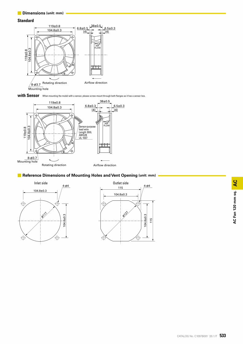
533CATALOG No. C1097B001 '20.1.IT
風吹出方向
AIR-FLOW
104.8±0.3119±0.8 38±0.5
6.8±0.3(4) (4)
6.5±0.311
9±0.
810
4.8±
0.3
8-ø3.7取付用穴
回転方向
8-ø3.7取付用穴
センサ用リード線長さ300LAWG 28UL 1007
38±0.56.8±0.3 6.5±0.3
AIR-FLOW
104.8±0.3
119±0.8
104.
8±0.
311
9 ±0.
8
(4) (4)
回転方向 風吹出方向
104.8±0.3
104.
8±0.
3
4-ø4
104.8±0.3
115
104.
8±0.
3
115
ø117
ø127
4-ø4 AC
AC
Fan
120
mm
sq
.
Standard
with Sensor
Outlet sideInlet side
Rotating direction Airflow direction
Mounting hole
Mounting holeRotating direction Airflow direction
Sensor-purposelead wireLength 300LAWG28UL 1007
When mounting the model with a sensor, please screw-mount through both flanges as it has a sensor box.
■ Dimensions (unit: mm)
■ Reference Dimensions of Mounting Holes and Vent Opening (unit: mm)
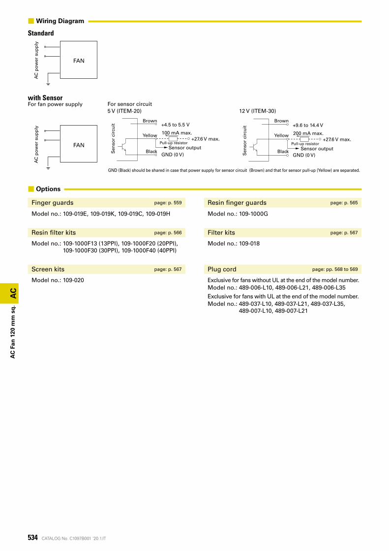
534 CATALOG No. C1097B001 '20.1.IT
AC電源 ファン
AC電源 ファン
AC
AC
Fan
120
mm
sq
.
■ Options
Finger guards page: p. 559 Resin finger guards page: p. 565
Model no.: 109-019E, 109-019K, 109-019C, 109-019H Model no.: 109-1000G
Resin filter kits page: p. 566 Filter kits page: p. 567
Model no.: 109-1000F13 (13PPI), 109-1000F20 (20PPI), 109-1000F30 (30PPI), 109-1000F40 (40PPI)
Model no.: 109-018
Screen kits page: p. 567 Plug cord page: pp. 568 to 569
Model no.: 109-020 Exclusive for fans without UL at the end of the model number.Model no.: 489-006-L10, 489-006-L21, 489-006-L35
Exclusive for fans with UL at the end of the model number.Model no.: 489-037-L10, 489-037-L21, 489-037-L35,
489-007-L10, 489-007-L21
StandardA
C p
ow
er s
up
ply
FAN
■Wiring Diagram
with SensorFor fan power supply
AC
po
wer
su
pp
ly
Sen
sor
circ
uit
Brown
Yellow
Black
Pull-up resistor
+4.5 to 5.5 V
GND (0 V)
+27.6 V max.100 mA max.
Sensor output
Sen
sor
circ
uit
Brown
Yellow
Black
Pull-up resistor
+9.6 to 14.4 V
GND (0 V)
+27.6 V max.200 mA max.
Sensor output
For sensor circuit5 V (ITEM-20) 12 V (ITEM-30)
GND (Black) should be shared in case that power supply for sensor circuit (Brown) and that for sensor pull-up (Yellow) are separated.
FAN
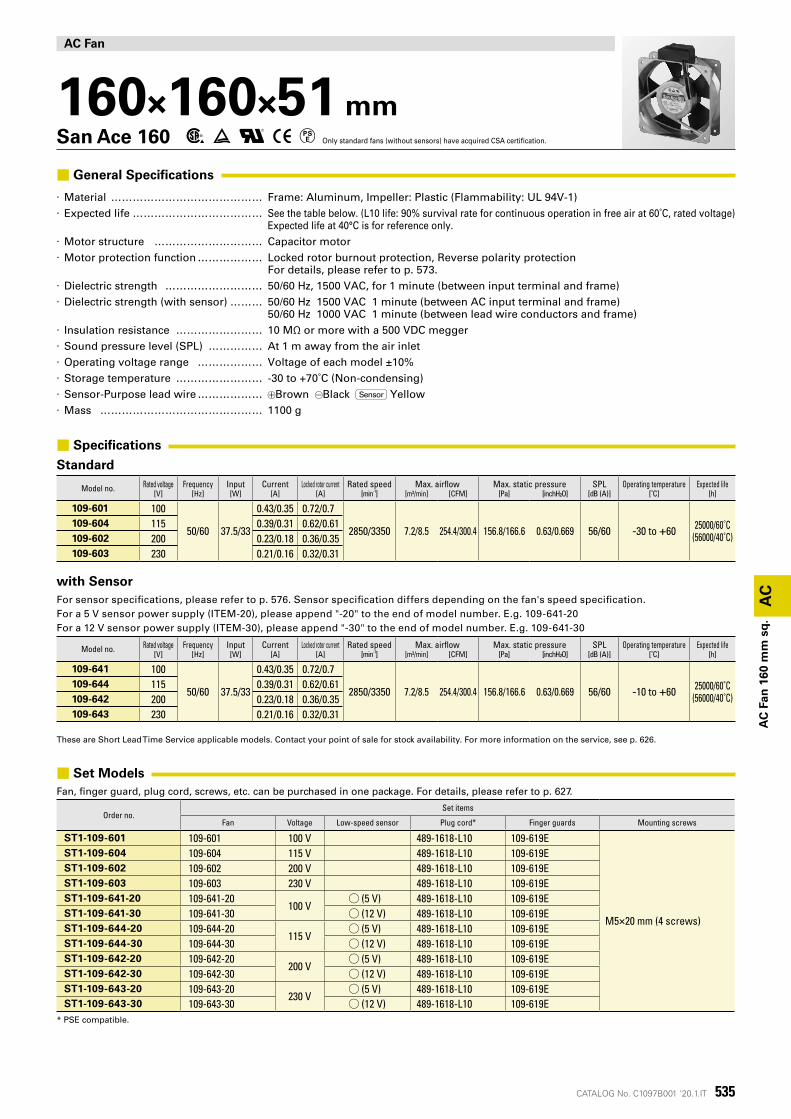
535CATALOG No. C1097B001 '20.1.IT
AC
AC
Fan
160
mm
sq
.
AC Fan
160×160×51 mmSan Ace 160 Only standard fans (without sensors) have acquired CSA certification.
■ General Specifications
· Material �������������� Frame: Aluminum, Impeller: Plastic (Flammability: UL 94V-1) · Expected life ������������ See the table below. (L10 life: 90% survival rate for continuous operation in free air at 60˚C, rated voltage)
Expected life at 40°C is for reference only. · Motor structure ���������� Capacitor motor · Motor protection function ������ Locked rotor burnout protection, Reverse polarity protection
For details, please refer to p. 573. · Dielectric strength ��������� 50/60 Hz, 1500 VAC, for 1 minute (between input terminal and frame) · Dielectric strength (with sensor) ��� 50/60 Hz 1500 VAC 1 minute (between AC input terminal and frame)
50/60 Hz 1000 VAC 1 minute (between lead wire conductors and frame) · Insulation resistance �������� 10 MΩ or more with a 500 VDC megger · Sound pressure level (SPL) ����� At 1 m away from the air inlet · Operating voltage range ������ Voltage of each model ±10% · Storage temperature �������� -30 to +70˚C (Non-condensing) · Sensor-Purpose lead wire ������ Brown Black Sensor Yellow · Mass ��������������� 1100 g
■ Specifications
Standard
Model no. Rated voltage Frequency Input Current Locked rotor current Rated speed Max. airflow Max. static pressure SPL Operating temperature Expected life[V] [Hz] [W] [A] [A] [min-1] [m³/min] [CFM] [Pa] [inchH²O] [dB (A)] [˚C] [h]
109-601 100
50/60 37.5/33
0.43/0.35 0.72/0.7
2850/3350 7.2/8.5 254.4/300.4 156.8/166.6 0.63/0.669 56/60 -30 to +60 25000/60˚C(56000/40˚C)
109-604 115 0.39/0.31 0.62/0.61109-602 200 0.23/0.18 0.36/0.35109-603 230 0.21/0.16 0.32/0.31
with SensorFor sensor specifications, please refer to p. 576. Sensor specification differs depending on the fan's speed specification.For a 5 V sensor power supply (ITEM-20), please append "-20" to the end of model number. E.g. 109-641-20For a 12 V sensor power supply (ITEM-30), please append "-30" to the end of model number. E.g. 109-641-30
Model no. Rated voltage Frequency Input Current Locked rotor current Rated speed Max. airflow Max. static pressure SPL Operating temperature Expected life[V] [Hz] [W] [A] [A] [min-1] [m³/min] [CFM] [Pa] [inchH²O] [dB (A)] [˚C] [h]
109-641 100
50/60 37.5/33
0.43/0.35 0.72/0.7
2850/3350 7.2/8.5 254.4/300.4 156.8/166.6 0.63/0.669 56/60 -10 to +60 25000/60˚C(56000/40˚C)
109-644 115 0.39/0.31 0.62/0.61109-642 200 0.23/0.18 0.36/0.35109-643 230 0.21/0.16 0.32/0.31
These are Short Lead Time Service applicable models. Contact your point of sale for stock availability. For more information on the service, see p. 626.
■ Set ModelsFan, finger guard, plug cord, screws, etc. can be purchased in one package. For details, please refer to p. 627.
Order no.Set items
Fan Voltage Low-speed sensor Plug cord* Finger guards Mounting screws
ST1-109-601 109-601 100 V 489-1618-L10 109-619E
M5×20 mm (4 screws)
ST1-109-604 109-604 115 V 489-1618-L10 109-619EST1-109-602 109-602 200 V 489-1618-L10 109-619EST1-109-603 109-603 230 V 489-1618-L10 109-619EST1-109-641-20 109-641-20
100 V◯ (5 V) 489-1618-L10 109-619E
ST1-109-641-30 109-641-30 ◯ (12 V) 489-1618-L10 109-619EST1-109-644-20 109-644-20
115 V◯ (5 V) 489-1618-L10 109-619E
ST1-109-644-30 109-644-30 ◯ (12 V) 489-1618-L10 109-619EST1-109-642-20 109-642-20
200 V◯ (5 V) 489-1618-L10 109-619E
ST1-109-642-30 109-642-30 ◯ (12 V) 489-1618-L10 109-619EST1-109-643-20 109-643-20
230 V◯ (5 V) 489-1618-L10 109-619E
ST1-109-643-30 109-643-30 ◯ (12 V) 489-1618-L10 109-619E* PSE compatible.
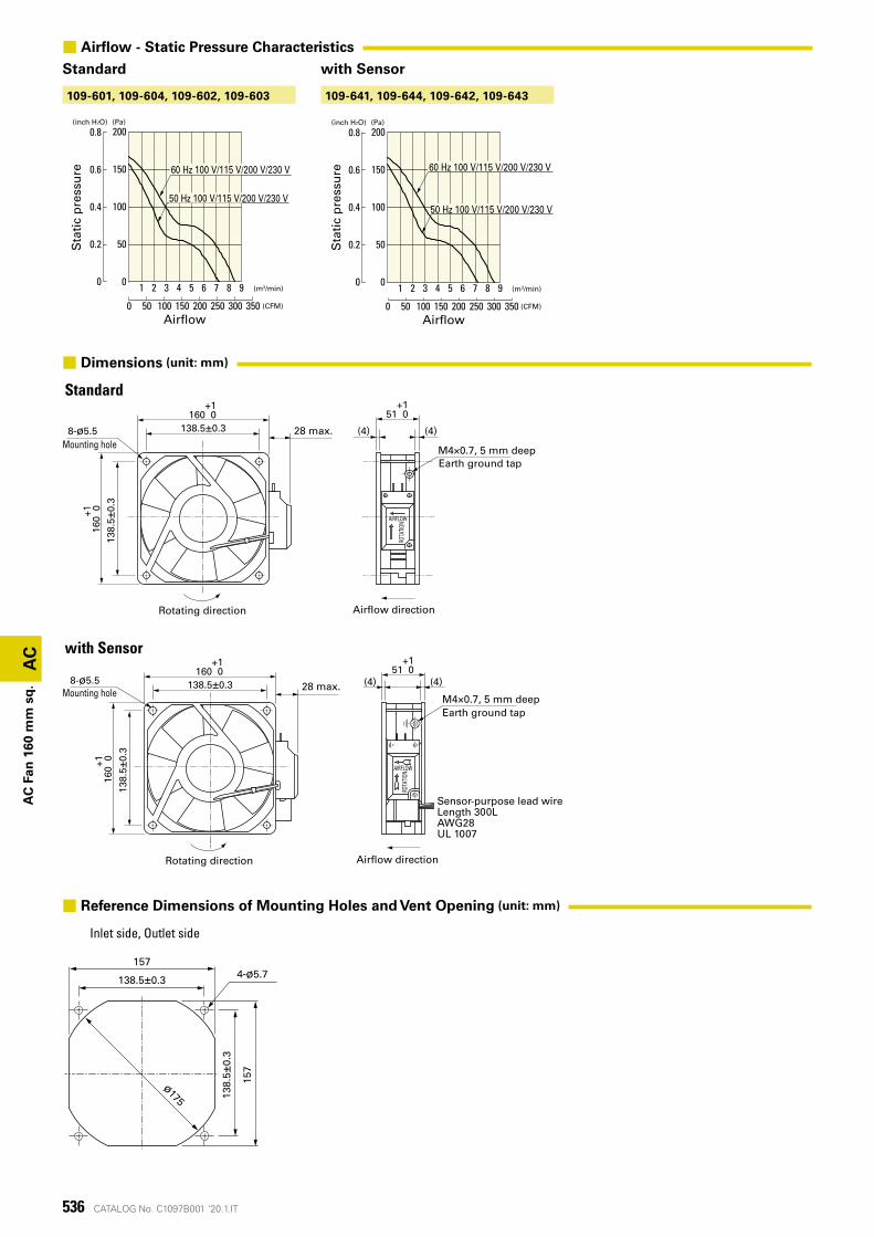
536 CATALOG No. C1097B001 '20.1.IT
28以下138.5±0.3 (4) (4)
M4×0.7深5アース用タップ
138.
5±0.
3
+151 0
AIRFLOW
ROTA
TION
+1160 0
+116
0 0
8-ø5.5取付用穴
センサ用リード線長さ300LAWG28UL 1007
風吹出方向回転方向
138.
5±0.
3
157
4-ø5.7
ø175
138.5±0.3
157
AIRFLOW
ROTA
TION
28以下138.5±0.3 (4) (4)
M4×0.7深5アース用タップ
138.
5±0.
3
+116
0 0
+1160 0
+151 0
8-ø5.5取付用穴
風吹出方向回転方向
(Pa)(inch H2O)
1 2 3 4 5 6 7 8 9
0.8
0.6
0.4
0.2
0
200
150
100
50
0
静圧
0 50 100 200150 250 300 350 (CFM)
(m3/min)
風量
60 Hz 100 V/115 V/200 V/230 V
50 Hz 100 V/115 V/200 V/230 V
(Pa)(inch H2O)
1 2 3 4 5 6 7 98
0.8
0.6
0.4
0.2
0
200
150
100
50
0
静圧
0 50 100 200150 250 350300 (CFM)
(m3/min)
風量
60 Hz 100 V/115 V/200 V/230 V
50 Hz 100 V/115 V/200 V/230 V
109-641, 109-644, 109-642, 109-643109-601, 109-604, 109-602, 109-603
AC
AC
Fan
160
mm
sq
.
Standard
with Sensor
Inlet side, Outlet side
M4×0.7, 5 mm deep
M4×0.7, 5 mm deep
Earth ground tap
Earth ground tap
28 max.
28 max.
Rotating direction
Rotating direction
Airflow direction
Airflow direction
Mounting hole
Mounting hole
Sensor-purpose lead wireLength 300LAWG28UL 1007
Sta
tic
pre
ssu
re
Sta
tic
pre
ssu
reAirflow Airflow
■ Airflow - Static Pressure Characteristics
Standard with Sensor
■ Dimensions (unit: mm)
■ Reference Dimensions of Mounting Holes and Vent Opening (unit: mm)
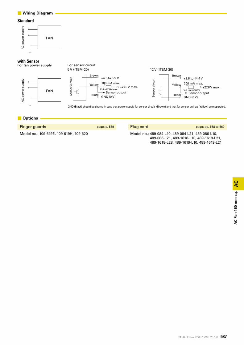
537CATALOG No. C1097B001 '20.1.IT
AC電源 ファン
AC電源 ファン
AC
AC
Fan
160
mm
sq
.
■ Options
Finger guards page: p. 559 Plug cord page: pp. 568 to 569
Model no.: 109-619E, 109-619H, 109-620 Model no.: 489-084-L10, 489-084-L21, 489-086-L10, 489-086-L21, 489-1618-L10, 489-1618-L21, 489-1618-L28, 489-1619-L10, 489-1619-L21
StandardA
C p
ow
er s
up
ply
FAN
■Wiring Diagram
with SensorFor fan power supply
AC
po
wer
su
pp
ly
Sen
sor
circ
uit
Brown
Yellow
Black
Pull-up resistor
+4.5 to 5.5 V
GND (0 V)
+27.6 V max.100 mA max.
Sensor output
Sen
sor
circ
uit
Brown
Yellow
Black
Pull-up resistor
+9.6 to 14.4 V
GND (0 V)
+27.6 V max.200 mA max.
Sensor output
For sensor circuit5 V (ITEM-20) 12 V (ITEM-30)
GND (Black) should be shared in case that power supply for sensor circuit (Brown) and that for sensor pull-up (Yellow) are separated.
FAN
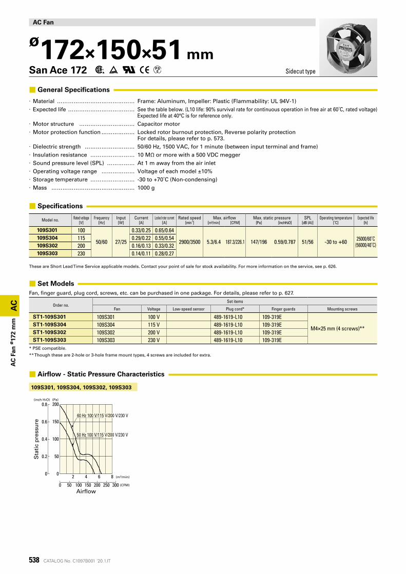
538 CATALOG No. C1097B001 '20.1.IT
109S301, 109S304, 109S302, 109S303
(Pa)(inch H2O)
2 4 6 8
0.8
0.6
0.4
0.2
0
200
150
100
50
0
静圧
0 50 100 200150 250 300 (CFM)
(m3/min)
風量
60 Hz 100 V/115 V/200 V/230 V
50 Hz 100 V/115 V/200 V/230 V
AC
AC
Fan
ø17
2 m
m
AC Fan
ø172×150×51 mmSan Ace 172 Sidecut type
■ General Specifications
· Material �������������� Frame: Aluminum, Impeller: Plastic (Flammability: UL 94V-1) · Expected life ������������ See the table below. (L10 life: 90% survival rate for continuous operation in free air at 60˚C, rated voltage)
Expected life at 40°C is for reference only. · Motor structure ���������� Capacitor motor · Motor protection function ������ Locked rotor burnout protection, Reverse polarity protection
For details, please refer to p. 573. · Dielectric strength ��������� 50/60 Hz, 1500 VAC, for 1 minute (between input terminal and frame) · Insulation resistance �������� 10 MΩ or more with a 500 VDC megger · Sound pressure level (SPL) ����� At 1 m away from the air inlet · Operating voltage range ������ Voltage of each model ±10% · Storage temperature �������� -30 to +70˚C (Non-condensing) · Mass ��������������� 1000 g
■ Specifications
Model no. Rated voltage Frequency Input Current Locked rotor current Rated speed Max. airflow Max. static pressure SPL Operating temperature Expected life[V] [Hz] [W] [A] [A] [min-1] [m³/min] [CFM] [Pa] [inchH²O] [dB (A)] [˚C] [h]
109S301 100
50/60 27/25
0.33/0.25 0.65/0.64
2900/3500 5.3/6.4 187.3/226.1 147/196 0.59/0.787 51/56 -30 to +60 25000/60˚C(56000/40˚C)
109S304 115 0.29/0.22 0.55/0.54109S302 200 0.16/0.13 0.33/0.32109S303 230 0.14/0.11 0.28/0.27
These are Short Lead Time Service applicable models. Contact your point of sale for stock availability. For more information on the service, see p. 626.
■ Set ModelsFan, finger guard, plug cord, screws, etc. can be purchased in one package. For details, please refer to p. 627.
Order no.Set items
Fan Voltage Low-speed sensor Plug cord* Finger guards Mounting screws
ST1-109S301 109S301 100 V 489-1619-L10 109-319E
M4×25 mm (4 screws)**ST1-109S304 109S304 115 V 489-1619-L10 109-319EST1-109S302 109S302 200 V 489-1619-L10 109-319EST1-109S303 109S303 230 V 489-1619-L10 109-319E
* PSE compatible.
** Though these are 2-hole or 3-hole frame mount types, 4 screws are included for extra.
■ Airflow - Static Pressure Characteristics
Sta
tic
pre
ssu
re
Airflow
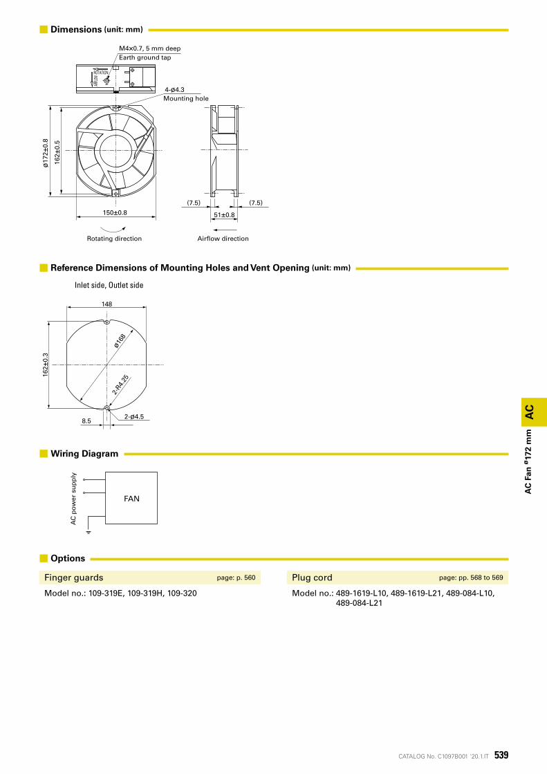
539CATALOG No. C1097B001 '20.1.IT
AC電源 ファン
AC
4-ø4.3取付用穴
ROTATION
AIRFLO
W
ø17
2±0.
8
150±0.8
162±
0.5
M4×0.7深5アース用タップ
(7.5) (7.5)
51±0.8
風吹出方向回転方向
ø168
2-R4
.25
2-ø4.58.5
162±
0.3
148
AC
Fan
ø17
2 m
m
Inlet side, Outlet side
Rotating direction Airflow direction
Mounting hole
M4×0.7, 5 mm deepEarth ground tap
■ Dimensions (unit: mm)
■ Reference Dimensions of Mounting Holes and Vent Opening (unit: mm)
■ Options
Finger guards page: p. 560 Plug cord page: pp. 568 to 569
Model no.: 109-319E, 109-319H, 109-320 Model no.: 489-1619-L10, 489-1619-L21, 489-084-L10, 489-084-L21
AC
po
wer
su
pp
ly
FAN
■Wiring Diagram
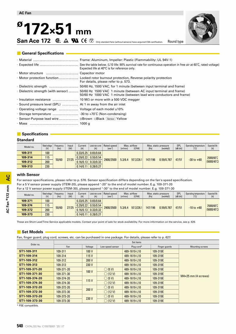
540 CATALOG No. C1097B001 '20.1.IT
AC
AC
Fan
ø17
2 m
m
AC Fan
ø172×51 mmSan Ace 172 Only standard fans (without sensors) have acquired CSA certification. Round type
■ General Specifications
· Material �������������� Frame: Aluminum, Impeller: Plastic (Flammability: UL 94V-1) · Expected life ������������ See the table below. (L10 life: 90% survival rate for continuous operation in free air at 60˚C, rated voltage)
Expected life at 40°C is for reference only. · Motor structure ���������� Capacitor motor · Motor protection function ������ Locked rotor burnout protection, Reverse polarity protection
For details, please refer to p. 573. · Dielectric strength ��������� 50/60 Hz, 1500 VAC, for 1 minute (between input terminal and frame) · Dielectric strength (with sensor) ��� 50/60 Hz 1500 VAC 1 minute (between AC input terminal and frame)
50/60 Hz 1000 VAC 1 minute (between lead wire conductors and frame) · Insulation resistance �������� 10 MΩ or more with a 500 VDC megger · Sound pressure level (SPL) ����� At 1 m away from the air inlet · Operating voltage range ������ Voltage of each model ±10% · Storage temperature �������� -30 to +70˚C (Non-condensing) · Sensor-Purpose lead wire ������ Brown Black Sensor Yellow · Mass ��������������� 1000 g
■ Specifications
Standard
Model no. Rated voltage Frequency Input Current Locked rotor current Rated speed Max. airflow Max. static pressure SPL Operating temperature Expected life[V] [Hz] [W] [A] [A] [min-1] [m³/min] [CFM] [Pa] [inchH²O] [dB (A)] [˚C] [h]
109-311 100
50/60 27/25
0.33/0.25 0.65/0.64
2900/3500 5.3/6.4 187.3/226.1 147/196 0.59/0.787 47/51 -30 to +60 25000/60˚C(56000/40˚C)
109-314 115 0.29/0.22 0.55/0.54109-312 200 0.16/0.13 0.33/0.32109-313 230 0.14/0.11 0.28/0.27
with SensorFor sensor specifications, please refer to p. 576. Sensor specification differs depending on the fan's speed specification.For a 5 V sensor power supply (ITEM-20), please append "-20" to the end of model number. E.g. 109-371-20For a 12 V sensor power supply (ITEM-30), please append "-30" to the end of model number. E.g. 109-371-30
Model no. Rated voltage Frequency Input Current Locked rotor current Rated speed Max. airflow Max. static pressure SPL Operating temperature Expected life[V] [Hz] [W] [A] [A] [min-1] [m³/min] [CFM] [Pa] [inchH²O] [dB (A)] [˚C] [h]
109-371 100
50/60 27/25
0.33/0.25 0.65/0.64
2900/3500 5.3/6.4 187.3/226.1 147/196 0.59/0.787 47/51 -10 to +60 25000/60˚C(56000/40˚C)
109-374 115 0.29/0.22 0.55/0.54109-372 200 0.16/0.13 0.33/0.32109-373 230 0.14/0.11 0.28/0.27
These are Short Lead Time Service applicable models. Contact your point of sale for stock availability. For more information on the service, see p. 626.
■ Set ModelsFan, finger guard, plug cord, screws, etc. can be purchased in one package. For details, please refer to p. 627.
Order no.Set items
Fan Voltage Low-speed sensor Plug cord* Finger guards Mounting screws
ST1-109-311 109-311 100 V 489-1619-L10 109-319E
M4×25 mm (4 screws)
ST1-109-314 109-314 115 V 489-1619-L10 109-319EST1-109-312 109-312 200 V 489-1619-L10 109-319EST1-109-313 109-313 230 V 489-1619-L10 109-319EST1-109-371-20 109-371-20
100 V◯ (5 V) 489-1619-L10 109-319E
ST1-109-371-30 109-371-30 ◯ (12 V) 489-1619-L10 109-319EST1-109-374-20 109-374-20
115 V◯ (5 V) 489-1619-L10 109-319E
ST1-109-374-30 109-374-30 ◯ (12 V) 489-1619-L10 109-319EST1-109-372-20 109-372-20
200 V◯ (5 V) 489-1619-L10 109-319E
ST1-109-372-30 109-372-30 ◯ (12 V) 489-1619-L10 109-319EST1-109-373-20 109-373-20
230 V◯ (5 V) 489-1619-L10 109-319E
ST1-109-373-30 109-373-30 ◯ (12 V) 489-1619-L10 109-319E* PSE compatible.
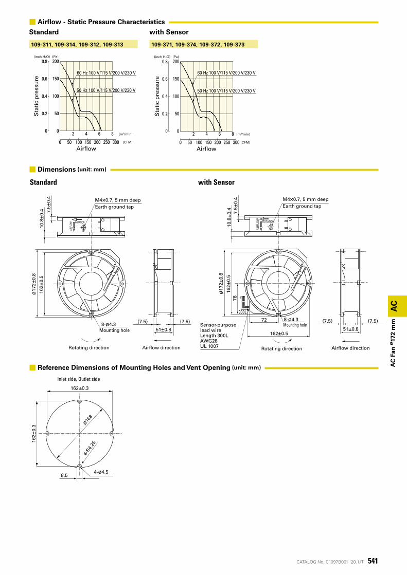
541CATALOG No. C1097B001 '20.1.IT
(Pa)(inch H2O)
2 4 6 8
0.8
0.6
0.4
0.2
0
200
150
100
50
0
静圧
0 50 100 200150 250 300 (CFM)
(m3/min)
風量
60 Hz 100 V/115 V/200 V/230 V
50 Hz 100 V/115 V/200 V/230 V
ø168
162±
0.3
162±0.3
4-ø4.5
4-R4
.25
8.5
(Pa)(inch H2O)
2 4 6 8
0.8
0.6
0.4
0.2
0
200
150
100
50
0
静圧
0 50 100 200150 250 300 (CFM)
(m3/min)
風量
60 Hz 100 V/115 V/200 V/230 V
50 Hz 100 V/115 V/200 V/230 V
109-371, 109-374, 109-372, 109-373109-311, 109-314, 109-312, 109-313
AC
51±0.8
(7.5) (7.5)
10.8
±0.4 7.
5 ±0.
4
ø17
2±0.
8
8-ø4.3取付用穴
162±
0.5
ROTATION
AIRF
LOW
風吹出方向回転方向
M4×0.7深5アース用タップ
センサ用リード線長さ300LAWG28UL 1007
162±0.5
72
300L
78
51±0.8
(7.5) (7.5)
10.8
±0.4 7.5 ±
0.4
ø17
2±0.
8
8-ø4.3取付用穴
162±
0.5
ROTATION
AIRF
LOW
風吹出方向回転方向
M4×0.7深5アース用タップ
AC
Fan
ø17
2 m
m
Sta
tic
pre
ssu
re
Sta
tic
pre
ssu
re
Airflow Airflow
with SensorStandard
Mounting hole
M4×0.7, 5 mm deepEarth ground tap
Rotating direction Airflow direction
M4×0.7, 5 mm deepEarth ground tap
Mounting hole
Rotating direction Airflow direction
Sensor-purpose lead wireLength 300LAWG28UL 1007
■ Airflow - Static Pressure Characteristics
Standard with Sensor
■ Dimensions (unit: mm)
■ Reference Dimensions of Mounting Holes and Vent Opening (unit: mm)
Inlet side, Outlet side
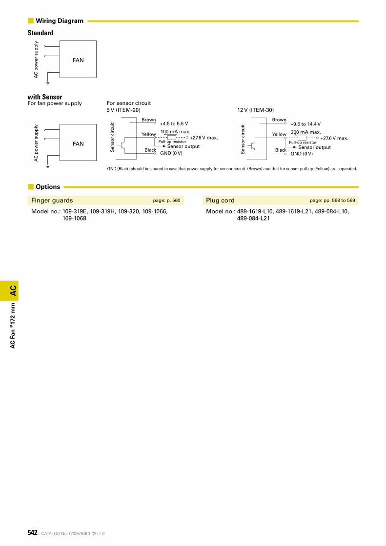
542 CATALOG No. C1097B001 '20.1.IT
AC電源 ファン
AC電源 ファン
AC
AC
Fan
ø17
2 m
m
■ Options
Finger guards page: p. 560 Plug cord page: pp. 568 to 569
Model no.: 109-319E, 109-319H, 109-320, 109-1066, 109-1068
Model no.: 489-1619-L10, 489-1619-L21, 489-084-L10, 489-084-L21
StandardA
C p
ow
er s
up
ply
FAN
■Wiring Diagram
with SensorFor fan power supply
AC
po
wer
su
pp
ly
Sen
sor
circ
uit
Brown
Yellow
Black
Pull-up resistor
+4.5 to 5.5 V
GND (0 V)
+27.6 V max.100 mA max.
Sensor output
Sen
sor
circ
uit
Brown
Yellow
Black
Pull-up resistor
+9.6 to 14.4 V
GND (0 V)
+27.6 V max.200 mA max.
Sensor output
For sensor circuit5 V (ITEM-20) 12 V (ITEM-30)
GND (Black) should be shared in case that power supply for sensor circuit (Brown) and that for sensor pull-up (Yellow) are separated.
FAN
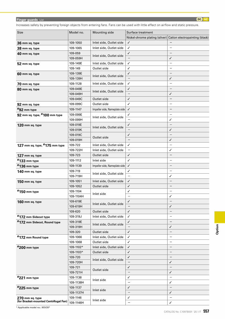
CATALOG No. C1097B001 '20.1.IT
ACDC
557
Op
tio
n
Finger guards List
Size Model no. Mounting side Surface treatment
Nickel-chrome plating (silver) Cation electropainting (black)
36 mm sq. type 109-1050 Inlet side, Outlet side ✓ -
38 mm sq. type 109-1065 Inlet side, Outlet side ✓ -
40 mm sq. type 109-059Inlet side, Outlet side
✓ -109-059H - ✓
52 mm sq. type 109-149E Inlet side, Outlet side ✓ -109-149 Outlet side ✓ -
60 mm sq. type 109-139EInlet side, Outlet side
✓ -109-139H - ✓
70 mm sq. type 109-1128 Inlet side, Outlet side ✓ -
80 mm sq. type 109-049EInlet side, Outlet side
✓ -109-049H - ✓
109-049C Outlet side ✓ -
92 mm sq. type 109-099C Outlet side ✓ -ø92 mm type 109-1147 Impeller side, Nameplate side ✓ -
92 mm sq. type, ø100 mm type 109-099EInlet side, Outlet side
✓ -109-099H - ✓
120 mm sq. type 109-019EInlet side, Outlet side
✓ -109-019K - ✓
109-019COutlet side
✓ -109-019H - ✓
127 mm sq. type, ø175 mm type 109-722 Inlet side, Outlet side ✓ -109-722H Inlet side, Outlet side - ✓
127 mm sq. type 109-723 Outlet side ✓ -ø133 mm type 109-1112 Inlet side ✓ -ø136 mm type 109-1139 Impeller side, Nameplate side ✓ -
140 mm sq. type 109-719Inlet side, Outlet side
✓ -109-719H - ✓
150 mm sq. type 109-1051 Inlet side, Outlet side ✓ -109-1052 Outlet side ✓ -
ø150 mm type 109-1104Inlet side
✓ -109-1104H - ✓
160 mm sq. type 109-619EInlet side, Outlet side
✓ -109-619H - ✓
109-620 Outlet side ✓ -ø172 mm Sidecut type 109-319J Inlet side, Outlet side ✓ -ø172 mm Sidecut, Round type 109-319E
Inlet side, Outlet side✓ -
109-319H - ✓
109-320 Outlet side ✓ -ø172 mm Round type 109-1066 Inlet side, Outlet side ✓ -
109-1068 Outlet side ✓ -ø200 mm type 109-1102* Inlet side, Outlet side ✓ -
109-1103* Outlet side ✓ -109-720
Inlet side, Outlet side✓ -
109-720H - ✓
109-721Outlet side
✓ -109-721H - ✓
ø221 mm type 109-1138Inlet side
✓ -109-1138H - ✓
ø225 mm type 109-1137Inlet side
✓ -109-1137H - ✓
270 mm sq. type(for Bracket-mounted Centrifugal Fan)
109-1146Inlet side
✓ -109-1146H - ✓
* Applicable model no.: 9GV20*
Increases safety by preventing foreign objects from entering fans. Fans can be used with little effect on air�ow and static pressure.
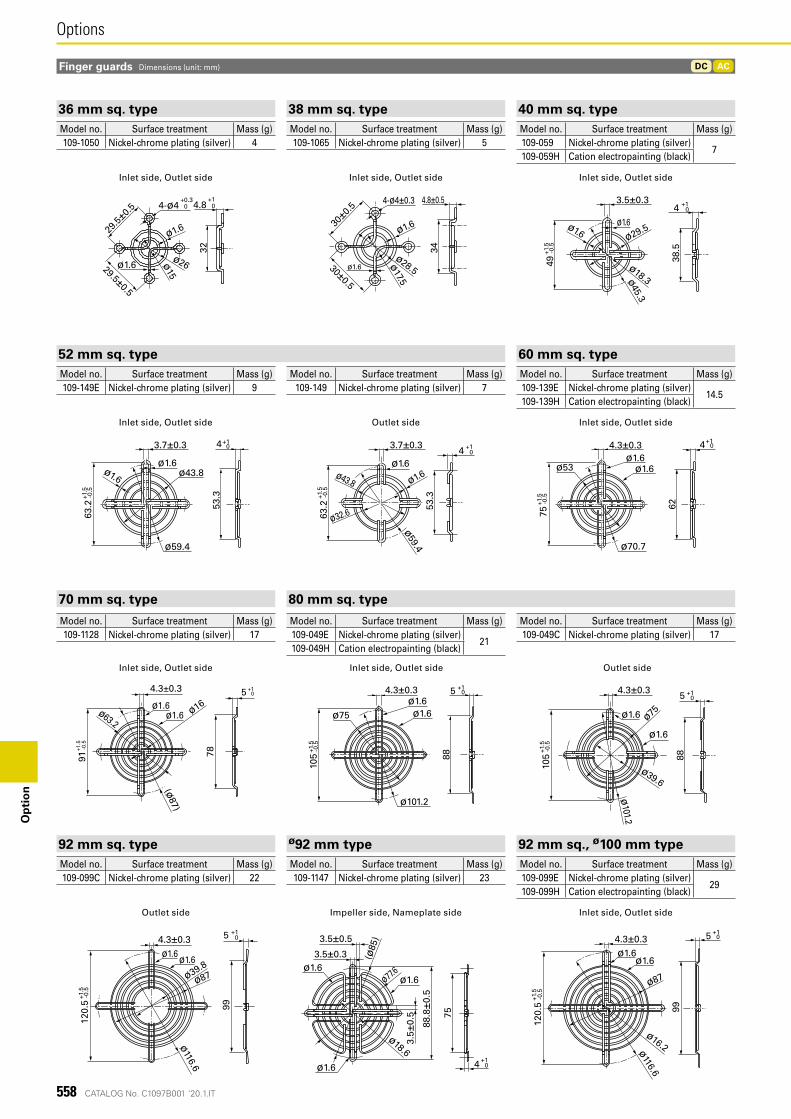
CATALOG No. C1097B001 '20.1.IT
ACDC
+1 4.8 0
29.5±
0.5 +0.3
4-ø4 0
29.5±0.5
ø1.6
ø1.6
ø15
ø26
32
30±0.5
4.8±0.5
30±0.5
4-ø4±0.3
ø1.6
ø17.5
ø1.6
34
ø28.5
38.5
ø1.6
3.5±0.3
49+1
.5-0
.5
4 +1 0
ø29.5ø1.6
ø18.3ø45.3
3.7±0.3
63.2
+1.5
-0.5
ø1.6
ø1.6
ø59.4
ø43.8
ø32.6
53.3
4 +1 0
3.7±0.3
ø1.6ø43.8
53.3
ø59.4
63.2
4+1 0
ø1.6
+1.5
-0.5
4.3±0.3ø1.6
ø1.6
62
ø53
ø70.775
4+1 0
+1.5
-0.5
78
(ø87)
91 +
1.5
-0.5
5 +1 0
4.3±0.3
ø16ø1.6
ø1.6ø63.2
105
+1.5
-0.5
5 +10
88
ø1.6
ø39.6
ø101.2
ø1.6 ø75
4.3±0.34.3±0.3ø1.6ø1.6
88
ø101.2
ø75
105
+1.5
-0.5
5 +1 0
120.
5+1
.5-0
.5
4.3±0.3
ø116.6
ø1.6ø1.6
ø39.8
ø87
99
5 +10 4.3±0.3
ø1.6ø1.6
ø116.6
ø87
120.
5+1
.5-0
.5
99
5 +1 0
ø16.2 +14 0
75
88.8
±0.5
(ø85
)
3.5±0.3
3.5±0.5
3.5±
0.5
ø77.6
ø18.6
ø1.6ø1.6
ø1.6
558
OptionsO
pti
on
Finger guards Dimensions (unit: mm)
Inlet side, Outlet side
Inlet side, Outlet side
Outlet side
Outlet side
Inlet side, Outlet side
Outlet side
Impeller side, Nameplate side
Inlet side, Outlet side
Inlet side, Outlet side
Inlet side, Outlet side
Inlet side, Outlet side
Inlet side, Outlet side
36 mm sq. type 38 mm sq. type 40 mm sq. typeModel no. Surface treatment Mass (g) Model no. Surface treatment Mass (g) Model no. Surface treatment Mass (g)109-1050 Nickel-chrome plating (silver) 4 109-1065 Nickel-chrome plating (silver) 5 109-059 Nickel-chrome plating (silver)
7109-059H Cation electropainting (black)
70 mm sq. type 80 mm sq. type
Model no. Surface treatment Mass (g) Model no. Surface treatment Mass (g) Model no. Surface treatment Mass (g)109-1128 Nickel-chrome plating (silver) 17 109-049E Nickel-chrome plating (silver)
21109-049C Nickel-chrome plating (silver) 17
109-049H Cation electropainting (black)
92 mm sq. type ø92 mm type 92 mm sq., ø100 mm typeModel no. Surface treatment Mass (g) Model no. Surface treatment Mass (g) Model no. Surface treatment Mass (g)109-099C Nickel-chrome plating (silver) 22 109-1147 Nickel-chrome plating (silver) 23 109-099E Nickel-chrome plating (silver)
29109-099H Cation electropainting (black)
52 mm sq. type 60 mm sq. typeModel no. Surface treatment Mass (g) Model no. Surface treatment Mass (g) Model no. Surface treatment Mass (g)109-149E Nickel-chrome plating (silver) 9 109-149 Nickel-chrome plating (silver) 7 109-139E Nickel-chrome plating (silver)
14.5109-139H Cation electropainting (black)
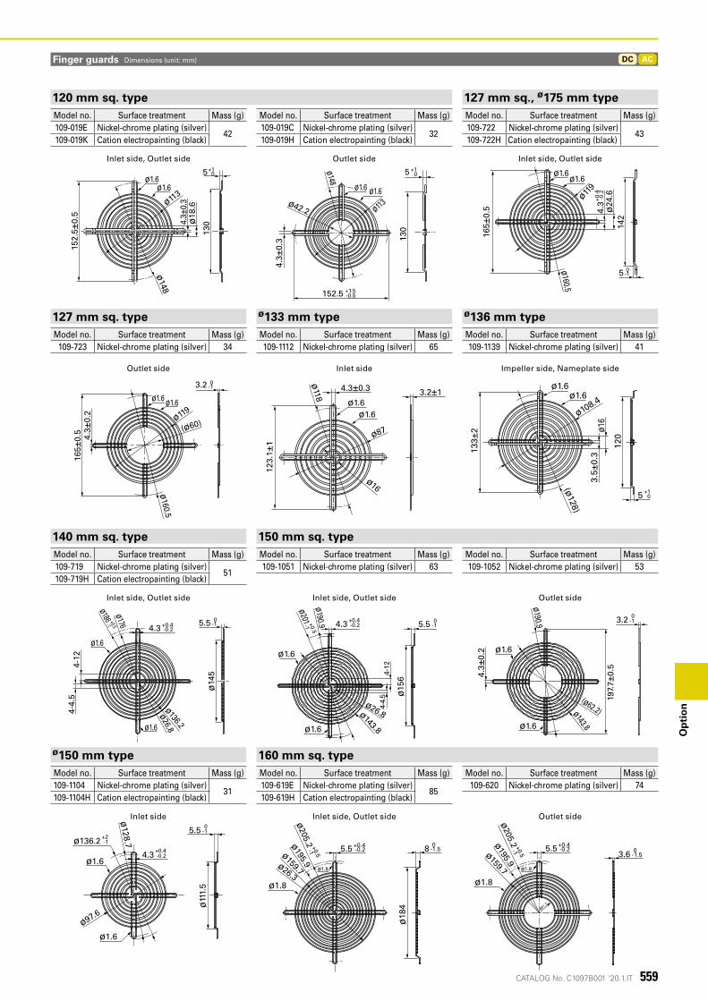
CATALOG No. C1097B001 '20.1.IT
ACDC
ø42.2
ø1.6 ø1.6
ø113
ø148
130
152.5 +1.5-0.5
5 +1 0
4.3±
0.3
152.
5±0.
5
5+1 0
ø1.6ø1.6
ø1134.
3±0.
3ø
18.6
130
ø148
ø119
ø1.6ø1.6
ø24
.6
+0.4
-0.2
ø160.5
0 -1
142
165±
0.5
5
4.3
3.2 0-1
ø1.6ø1.6
ø119
(ø60)
ø160.5
165±
0.5
4.3 ±
0.2
ø87
4.3±0.3
ø16
123.
1±1
3.2±1ø
118
ø1.6ø1.6
3.5±
0.313
3±2
120
(ø128)
ø16
ø108.4
5 +10
ø1.6ø1.6
ø1.6
ø1.6
ø136.2
ø176
ø186 +0.5 4.3
ø14
5
ø26.8
+0.4
4-4.
54-
12
5.5 0-1
-0.2
-1 4.3
ø1.6
ø1.6
ø15
6
ø26.8ø143.8
ø190.9
ø201 +0.5-1
4-4.
5
+0.4-0.2 5.5 0
-1
4-12
ø1.6
ø1.6
(ø62.2)ø143.8
4.3±
0.2
ø190.9
197.
7±0.
53.2 0
-1
ø11
1.5
ø128.7
ø97.6
ø1.6
ø1.6
4.3
ø136.2
5.5 0
-1
+0.4-0.2
+2-1
8 -1.50
ø1.8
ø205.2 +0.4
-0.25.5+0.5-1
ø26.3
ø159.7ø195.9
ø18
4
ø1.8
ø205.2 +0.5
-1ø159.7ø195.9
3.6 0-1.5
+0.4-0.25.5
ø1.8
ø61.7
ø1.8
559
Op
tio
n
Finger guards Dimensions (unit: mm)
Outlet sideInlet side, Outlet side Inlet side, Outlet side
120 mm sq. type 127 mm sq., ø175 mm typeModel no. Surface treatment Mass (g) Model no. Surface treatment Mass (g) Model no. Surface treatment Mass (g)109-019E Nickel-chrome plating (silver)
42109-019C Nickel-chrome plating (silver)
32109-722 Nickel-chrome plating (silver)
43109-019K Cation electropainting (black) 109-019H Cation electropainting (black) 109-722H Cation electropainting (black)
Outlet side Inlet side Impeller side, Nameplate side
127 mm sq. type ø133 mm type ø136 mm typeModel no. Surface treatment Mass (g) Model no. Surface treatment Mass (g) Model no. Surface treatment Mass (g)
109-723 Nickel-chrome plating (silver) 34 109-1112 Nickel-chrome plating (silver) 65 109-1139 Nickel-chrome plating (silver) 41
Inlet side, Outlet side
Inlet side
Inlet side, Outlet side
Inlet side, Outlet side
Outlet side
Outlet side
140 mm sq. type 150 mm sq. typeModel no. Surface treatment Mass (g) Model no. Surface treatment Mass (g) Model no. Surface treatment Mass (g)109-719 Nickel-chrome plating (silver)
51109-1051 Nickel-chrome plating (silver) 63 109-1052 Nickel-chrome plating (silver) 53
109-719H Cation electropainting (black)
ø150 mm type 160 mm sq. typeModel no. Surface treatment Mass (g) Model no. Surface treatment Mass (g) Model no. Surface treatment Mass (g)109-1104 Nickel-chrome plating (silver)
31109-619E Nickel-chrome plating (silver)
85109-620 Nickel-chrome plating (silver) 74
109-1104H Cation electropainting (black) 109-619H Cation electropainting (black)
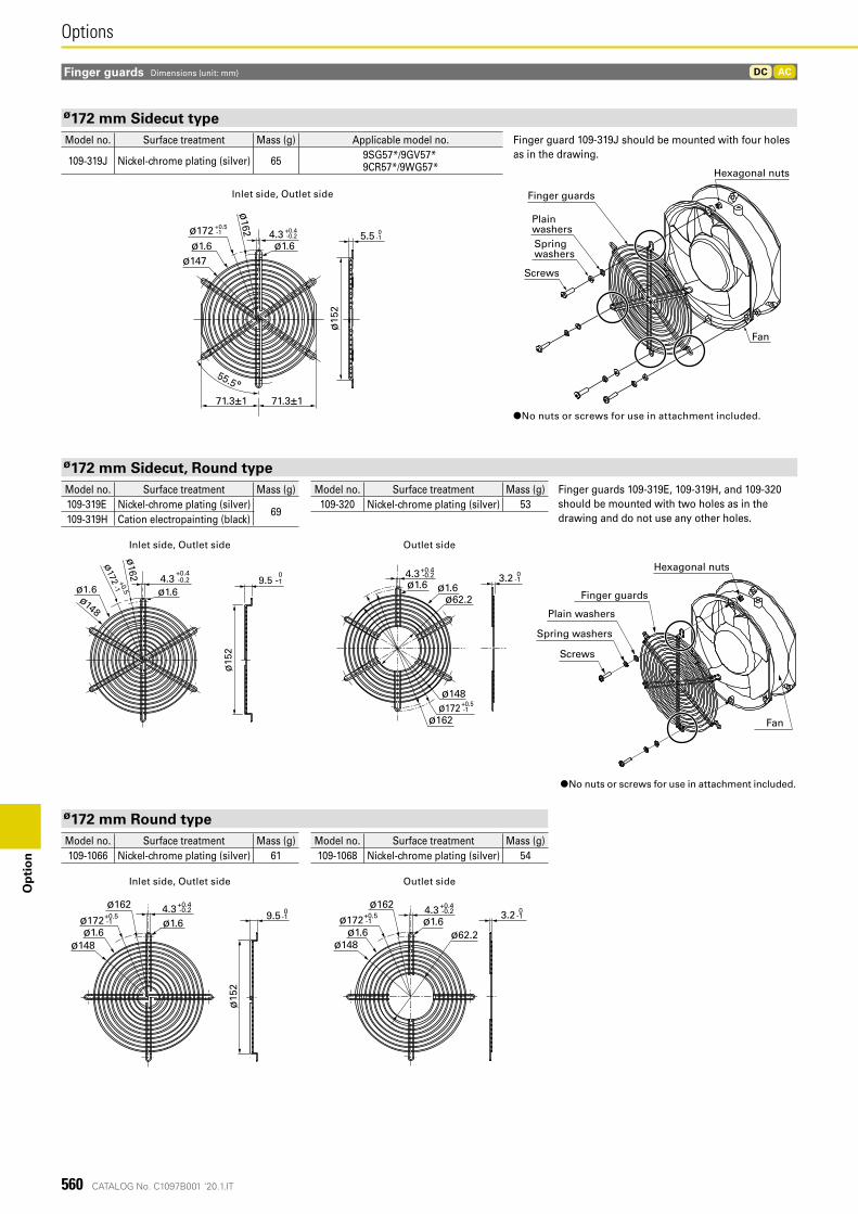
CATALOG No. C1097B001 '20.1.IT
ACDC
0-1
ø15
2
5.5+0.5-1ø172 +0.4
-0.24.3ø1.6ø1.6
55.5°
ø162
71.3±171.3±1
ø147
ø148
ø162
ø1.6 ø1.6
ø15
2
+0.44.3 -0.2
09.5 -1+0.5
ø172
-1
ø172 +0.5-1
ø148
ø162
ø62.2ø1.6ø1.6
4.3+0.4 -0.2 3.2 0
-1
ø1.6ø1.6
ø15
2
ø162
ø1724.3
9.5
ø148
+0.5-1
+0.4-0.2 0
-1 ø1.64.3 3.2
ø162
ø172
ø148ø1.6 ø62.2
+0.5-1
+0.4-0.2 0
-1
560
OptionsO
pti
on
Finger guards
Fan
Hexagonal nuts
Screws
Spring washers
Plain washers
Finger guards Dimensions (unit: mm)
Plain washers
Finger guards
Screws
Spring washers
Hexagonal nuts
Fan
ø172 mm Sidecut typeModel no. Surface treatment Mass (g) Applicable model no. Finger guard 109-319J should be mounted with four holes
as in the drawing.109-319J Nickel-chrome plating (silver) 65 9SG57*/9GV57*9CR57*/9WG57*
Inlet side, Outlet side
Inlet side, Outlet side
Outlet side
Outlet side
Inlet side, Outlet side
ø172 mm Sidecut, Round typeModel no. Surface treatment Mass (g) Model no. Surface treatment Mass (g) Finger guards 109-319E, 109-319H, and 109-320
should be mounted with two holes as in the drawing and do not use any other holes.
109-319E Nickel-chrome plating (silver)69
109-320 Nickel-chrome plating (silver) 53109-319H Cation electropainting (black)
ø172 mm Round typeModel no. Surface treatment Mass (g) Model no. Surface treatment Mass (g)109-1066 Nickel-chrome plating (silver) 61 109-1068 Nickel-chrome plating (silver) 54
●No nuts or screws for use in attachment included.
●No nuts or screws for use in attachment included.
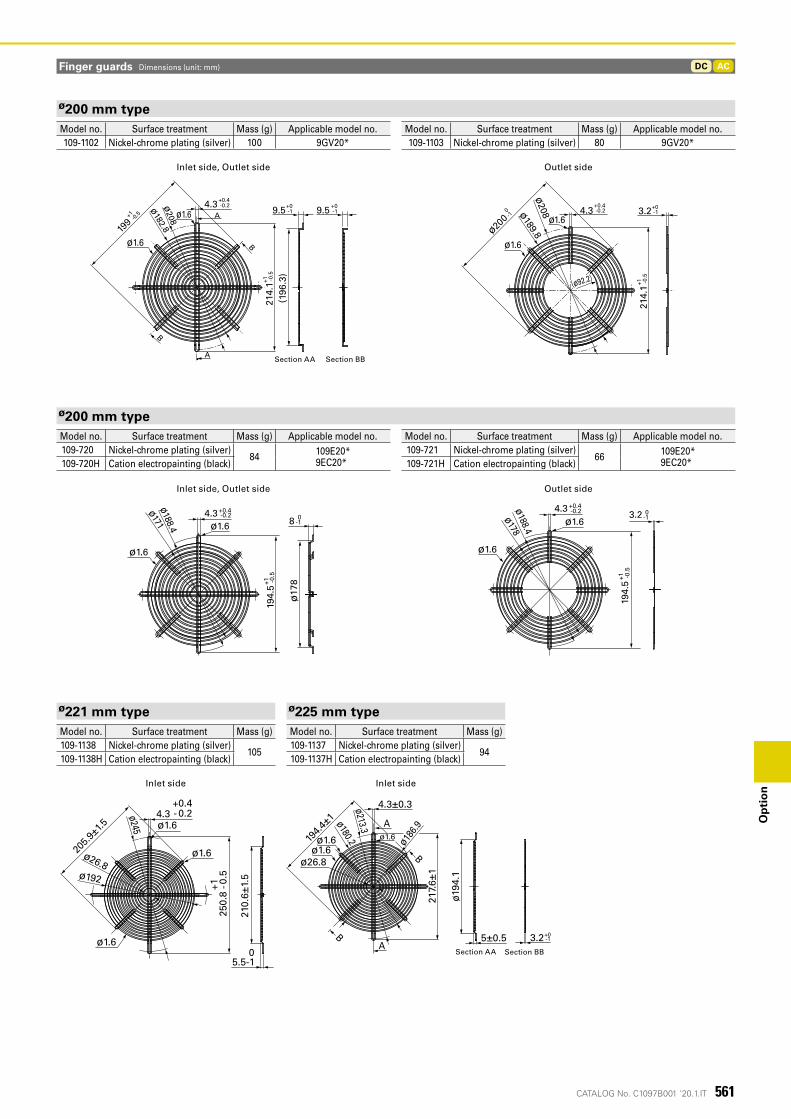
CATALOG No. C1097B001 '20.1.IT
ACDC
4.3
ø1.6
ø1.6-0.2+0.4
214.
1-0
.5+1
199
-0.5+1
9.5 -1+0 9.5 -1
+0
A
A
B
B
ø208
(196
.3)
ø182.8
断面BB断面AA
4.3 -0.2+0.4
3.2 -1+0
214.
1-0
.5+1
ø200 -1 0
ø1.6
ø1.6
ø189.8ø
208
(ø92.2)
+0.4-0.2
+1 -0.5
0-1
4.3
ø188.4
ø1.6
ø1.6 8
194.
5
ø17
8
ø171
0-1
+0.4-0.24.3ø188.4
ø178
ø1.6
ø1.6
+1 -0.5
194.
5
3.2
ø1.6
ø1.6
ø1.6
ø26.8
4.3+0.4- 0.2
250.
8+1 -0
.5
205.9
±1.5
210.
6±1.
5
ø245
05.5-1
ø192
A
A断面 AA 断面BB
B
Bø1.6
ø26.8
ø1.6
217.
6±1
4.3±0.3
194.4
±1
3.2+0-15±0.5
ø194
.1ø180.2
ø213.3
ø186
.9
ø1.6
561
Op
tio
n
Finger guards Dimensions (unit: mm)
Inlet side, Outlet side
Inlet side, Outlet side
Outlet side
Outlet side
ø200 mm typeModel no. Surface treatment Mass (g) Applicable model no. Model no. Surface treatment Mass (g) Applicable model no.109-1102 Nickel-chrome plating (silver) 100 9GV20* 109-1103 Nickel-chrome plating (silver) 80 9GV20*
ø200 mm typeModel no. Surface treatment Mass (g) Applicable model no. Model no. Surface treatment Mass (g) Applicable model no.109-720 Nickel-chrome plating (silver)
84 109E20*9EC20*
109-721 Nickel-chrome plating (silver)66 109E20*
9EC20*109-720H Cation electropainting (black) 109-721H Cation electropainting (black)
Inlet side Inlet side
ø221 mm type ø225 mm typeModel no. Surface treatment Mass (g) Model no. Surface treatment Mass (g)109-1138 Nickel-chrome plating (silver)
105109-1137 Nickel-chrome plating (silver)
94109-1138H Cation electropainting (black) 109-1137H Cation electropainting (black)
Section AA Section BB
Section AA Section BB
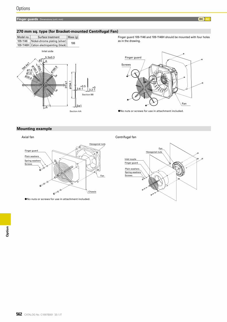
CATALOG No. C1097B001 '20.1.IT
A
B
5.3±0.3
194.4
±1
ø186.
9
ø26.8
ø180.2ø305.7
ø1.6ø1.6
ø2
A
B 3.2+0-1
5±1
ø19
4.1
311 ±
1
3.6+0.5-1
断面AA
断面BB
フィンガーガード
ネジ
ファン
ACDC
562
OptionsO
pti
on
Chassis
Fan
Hexagonal nuts
Screws
Spring washers
Plain washers
Finger guardFan
Hexagonal nuts
Inlet nozzle
Finger guard
ScrewsSpring washers
Plain washers
Fan
Finger guard
Screws
Section AA
Section BB
Finger guards Dimensions (unit: mm)
Inlet side
270 mm sq. type (for Bracket-mounted Centrifugal Fan)Model no. Surface treatment Mass (g) Finger guard 109-1146 and 109-1146H should be mounted with four holes
as in the drawing.109-1146 Nickel-chrome plating (silver)106
109-1146H Cation electropainting (black)
Mounting example
Axial fan Centrifugal fan
●No nuts or screws for use in attachment included.
●No nuts or screws for use in attachment included.
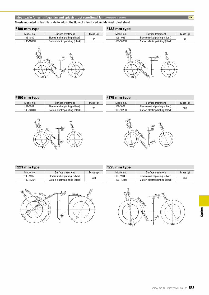
CATALOG No. C1097B001 '20.1.IT
7±1
ø139±
1ø
128±0.5
4-ø4.5±0.5
ø100±
0.5
(R6)
(1)
90°±1°(等配)
ø158±
0.5
ø170±
1
4-ø4.5±0.5
90°±1°(等配)
14±1(1)
(R10)
ø126±
0.5
90°±1°(等配)
4-ø4.3±0.5
ø128±
1
(R4.8)
(1)5±1
ø70±
0.5
ø116.6±
0.5 13±190°±1°(等配)
(1)
ø129±
1ø
118±0.5
ø85±
0.5
4-ø4.5±0.5
DC
90°±
1°(等配)
45°±1°60°±1°(等配)
6-ø5.5±0.5 118±1
ø245±0.5
4-ø4.3±0.5
ø155
.2±0.5ø252±1
(R22)
(0.8)21±1
ø242±0.5
ø210±0.5
ø223±1
4-4.5±0.5
90°±1°(等配)
(1.5)29.5±1
ø146±0.5
(R24)
563
Op
tio
n
(Each)
(Each)
(Each)
(Each)
Inlet nozzle for centrifugal fan and splash proof centrifugal fan Dimensions (unit: mm)
ø100 mm type ø133 mm typeModel no. Surface treatment Mass (g) Model no. Surface treatment Mass (g)109-1080 Electro nickel plating (silver)
80109-1069 Electro nickel plating (silver)
76109-1080H Cation electropainting (black) 109-1069H Cation electropainting (black)
ø150 mm type ø175 mm typeModel no. Surface treatment Mass (g) Model no. Surface treatment Mass (g)109-1081 Electro nickel plating (silver)
70109-1073 Electro nickel plating (silver)
100109-1081H Cation electropainting (black) 109-1073H Cation electropainting (black)
ø221 mm type ø225 mm typeModel no. Surface treatment Mass (g) Model no. Surface treatment Mass (g)109-1135 Electro nickel plating (silver)
230109-1134 Electro nickel plating (silver)
360109-1135H Cation electropainting (black) 109-1134H Cation electropainting (black)
Nozzle mounted in fan inlet side to adjust the flow of introduced air. Material: Steel sheet
(Each)
(Each)
(Eac
h)
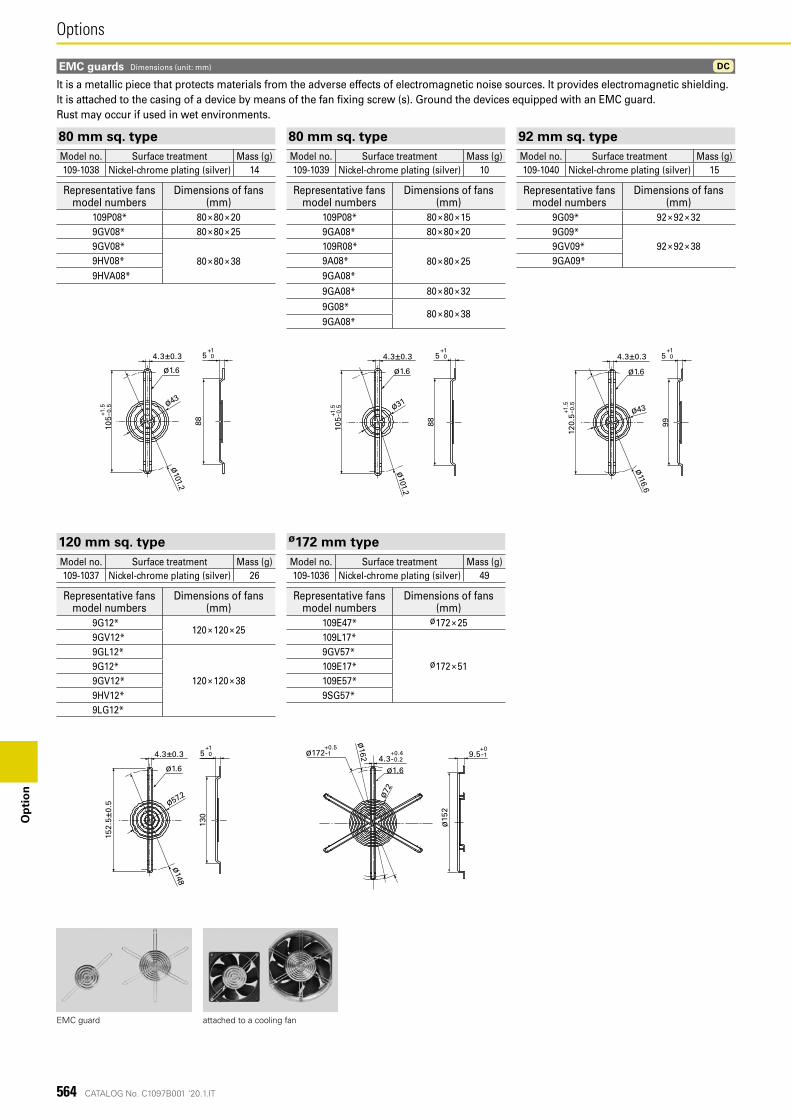
CATALOG No. C1097B001 '20.1.IT
+15 0
+1.5
105
-0.5
4.3±0.3
ø1.6
ø101.2
ø43
88
+1.5
105
-0.5
4.3±0.3+1
5 0
ø1.6
ø101.2
ø31
88
+1.5
120.
5-0
.5
4.3±0.3+1
5 0
ø116.6
ø1.6
ø43
99
152.
5±0.
5
4.3±0.3+1
5 0
ø1.6
ø148
ø57.2
130
ø15
2
+09.5-1
ø1.6
ø72
ø162 +0.4
+0.5
4.3-0.2ø172-1
DC
564
OptionsO
pti
on
EMC guard attached to a cooling fan
EMC guards Dimensions (unit: mm)
It is a metallic piece that protects materials from the adverse effects of electromagnetic noise sources. It provides electromagnetic shielding.It is attached to the casing of a device by means of the fan fixing screw (s). Ground the devices equipped with an EMC guard.Rust may occur if used in wet environments.
80 mm sq. type 80 mm sq. type 92 mm sq. typeModel no. Surface treatment Mass (g) Model no. Surface treatment Mass (g) Model no. Surface treatment Mass (g)109-1038 Nickel-chrome plating (silver) 14 109-1039 Nickel-chrome plating (silver) 10 109-1040 Nickel-chrome plating (silver) 15
Representative fans model numbers
Dimensions of fans(mm)
Representative fans model numbers
Dimensions of fans(mm)
Representative fans model numbers
Dimensions of fans(mm)
109P08* 80 × 80 × 20 109P08* 80 × 80 × 15 9G09* 92 × 92 × 329GV08* 80 × 80 × 25 9GA08* 80 × 80 × 20 9G09*
92 × 92 × 389GV08*80 × 80 × 38
109R08*80 × 80 × 25
9GV09*9HV08* 9A08* 9GA09*9HVA08* 9GA08*
9GA08* 80 × 80 × 32
9G08*80 × 80 × 38
9GA08*
120 mm sq. type ø172 mm typeModel no. Surface treatment Mass (g) Model no. Surface treatment Mass (g)109-1037 Nickel-chrome plating (silver) 26 109-1036 Nickel-chrome plating (silver) 49
Representative fans model numbers
Dimensions of fans(mm)
Representative fans model numbers
Dimensions of fans(mm)
9G12*120 × 120 × 25
109E47* ø172 × 259GV12* 109L17*
ø172 × 519GL12*
120 × 120 × 38
9GV57*9G12* 109E17*9GV12* 109E57*9HV12* 9SG57*9LG12*
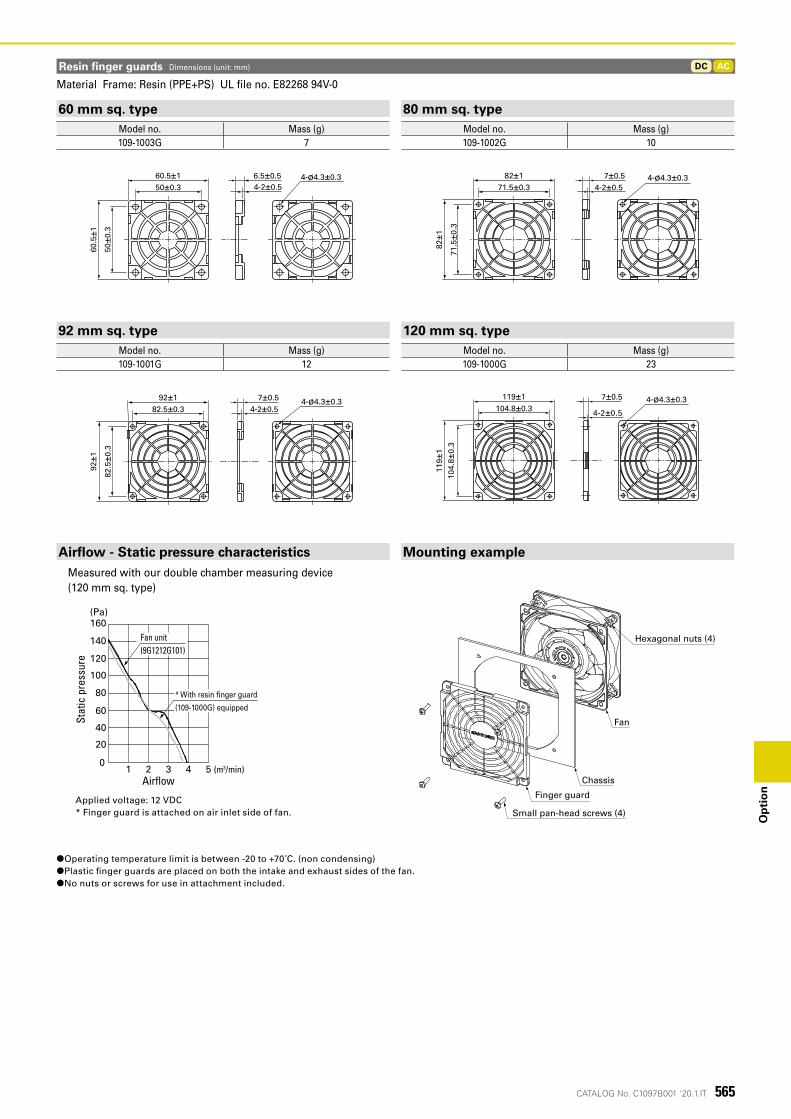
CATALOG No. C1097B001 '20.1.IT
60.5
±1
50±0
.3
60.5±150±0.3
4-ø4.3±0.36.5±0.54-2±0.5 4-2±0.5
82±1
82±1
71.5±0.3
71.5
±0.3
4-ø4.3±0.37±0.5
4-2±0.5
92±1
82.5
±0.3
92±182.5±0.3
4-ø4.3±0.37±0.5
4-2±0.5
119±
110
4.8±
0.3
119±1104.8±0.3
4-ø4.3±0.37±0.5
ACDC
565
Op
tio
n
Resin finger guards Dimensions (unit: mm)
Applied voltage: 12 VDC* Finger guard is attached on air inlet side of fan.
1 2 3 4 5
160 (Pa)
140
120
100
80
60
40
20
0
Stat
ic p
ress
ure
Air�ow(m3/min)
Fan unit (9G1212G101)
* With resin �nger guard
(109-1000G) equipped
Small pan-head screws (4)
Hexagonal nuts (4)
Fan
Finger guard
Chassis
60 mm sq. type 80 mm sq. typeModel no. Mass (g) Model no. Mass (g)109-1003G 7 109-1002G 10
92 mm sq. type 120 mm sq. typeModel no. Mass (g) Model no. Mass (g)109-1001G 12 109-1000G 23
Material Frame: Resin (PPE+PS) UL file no. E82268 94V-0
Airflow - Static pressure characteristics Mounting exampleMeasured with our double chamber measuring device (120 mm sq. type)
●Operating temperature limit is between -20 to +70˚C. (non condensing) ●Plastic finger guards are placed on both the intake and exhaust sides of the fan. ●No nuts or screws for use in attachment included.
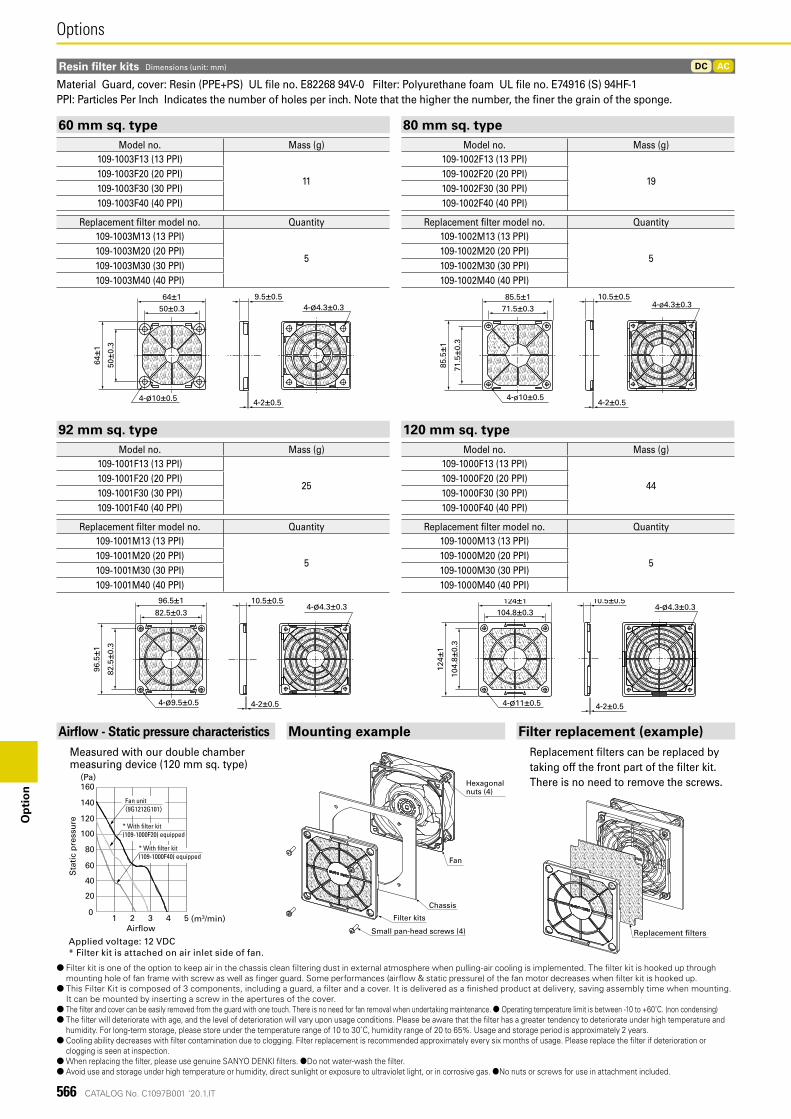
CATALOG No. C1097B001 '20.1.IT
9.5±0.5
4-2±0.5
64±1
4-ø10±0.5
50±0
.3
64±150±0.3 4-ø4.3±0.3
85.5±1
85.5
±1
4-ø10±0.5
71.5±0.3
71.5
±0.3
4-ø4.3±0.310.5±0.5
4-2±0.5
4-ø9.5±0.5
96.5
±182
.5±0
.3
96.5±1
82.5±0.34-ø4.3±0.3
10.5±0.5
4-2±0.5
10.5±0.5
4-2±0.54-ø11±0.5
124±
1
104.
8±0.
3
124±1104.8±0.3
4-ø4.3±0.3
ACDC
566
OptionsO
pti
on
Resin filter kits Dimensions (unit: mm)
Applied voltage: 12 VDC* Filter kit is attached on air inlet side of fan.
1 2 3 4 5 (m3/min)
160(Pa)
140
120
100
80
60
40
20
0
Sta
tic
pre
ssu
re
Air�ow
Fan unit(9G1212G101)
* With �lter kit (109-1000F20) equipped
* With �lter kit (109-1000F40) equipped
Hexagonal nuts (4)
Small pan-head screws (4)
Filter kits
Chassis
Fan
Airflow - Static pressure characteristics Mounting example Filter replacement (example)Measured with our double chamber measuring device (120 mm sq. type)
Replacement filters can be replaced by taking off the front part of the filter kit. There is no need to remove the screws.
● Filter kit is one of the option to keep air in the chassis clean �ltering dust in external atmosphere when pulling-air cooling is implemented. The �lter kit is hooked up through mounting hole of fan frame with screw as well as �nger guard. Some performances (air�ow & static pressure) of the fan motor decreases when �lter kit is hooked up.
● This Filter Kit is composed of 3 components, including a guard, a �lter and a cover. It is delivered as a �nished product at delivery, saving assembly time when mounting. It can be mounted by inserting a screw in the apertures of the cover.
● The �lter and cover can be easily removed from the guard with one touch. There is no need for fan removal when undertaking maintenance. ● Operating temperature limit is between -10 to +60˚C. (non condensing) ● The �lter will deteriorate with age, and the level of deterioration will vary upon usage conditions. Please be aware that the �lter has a greater tendency to deteriorate under high temperature and
humidity. For long-term storage, please store under the temperature range of 10 to 30˚C, humidity range of 20 to 65%. Usage and storage period is approximately 2 years. ● Cooling ability decreases with �lter contamination due to clogging. Filter replacement is recommended approximately every six months of usage. Please replace the �lter if deterioration or
clogging is seen at inspection. ● When replacing the �lter, please use genuine SANYO DENKI �lters. ●Do not water-wash the �lter. ● Avoid use and storage under high temperature or humidity, direct sunlight or exposure to ultraviolet light, or in corrosive gas. ●No nuts or screws for use in attachment included.
Material Guard, cover: Resin (PPE+PS) UL file no. E82268 94V-0 Filter: Polyurethane foam UL file no. E74916 (S) 94HF-1PPI: Particles Per Inch Indicates the number of holes per inch. Note that the higher the number, the finer the grain of the sponge.
60 mm sq. type 80 mm sq. typeModel no. Mass (g) Model no. Mass (g)
109-1003F13 (13 PPI)
11
109-1002F13 (13 PPI)
19109-1003F20 (20 PPI) 109-1002F20 (20 PPI)109-1003F30 (30 PPI) 109-1002F30 (30 PPI)109-1003F40 (40 PPI) 109-1002F40 (40 PPI)
Replacement filter model no. Quantity Replacement filter model no. Quantity109-1003M13 (13 PPI)
5
109-1002M13 (13 PPI)
5109-1003M20 (20 PPI) 109-1002M20 (20 PPI)109-1003M30 (30 PPI) 109-1002M30 (30 PPI)109-1003M40 (40 PPI) 109-1002M40 (40 PPI)
92 mm sq. type 120 mm sq. typeModel no. Mass (g) Model no. Mass (g)
109-1001F13 (13 PPI)
25
109-1000F13 (13 PPI)
44109-1001F20 (20 PPI) 109-1000F20 (20 PPI)109-1001F30 (30 PPI) 109-1000F30 (30 PPI)109-1001F40 (40 PPI) 109-1000F40 (40 PPI)
Replacement filter model no. Quantity Replacement filter model no. Quantity109-1001M13 (13 PPI)
5
109-1000M13 (13 PPI)
5109-1001M20 (20 PPI) 109-1000M20 (20 PPI)109-1001M30 (30 PPI) 109-1000M30 (30 PPI)109-1001M40 (40 PPI) 109-1000M40 (40 PPI)
Replacement �lters
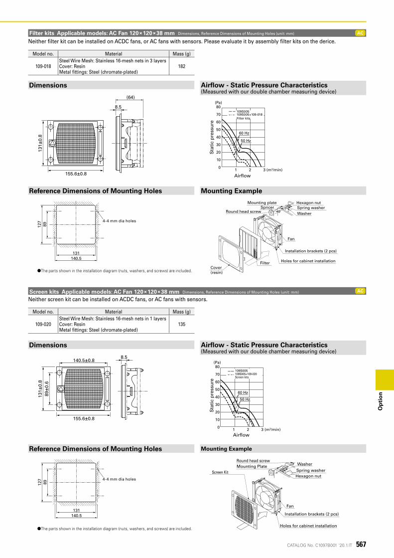
CATALOG No. C1097B001 '20.1.IT
131±
0.8
155.6±0.8
8.5
(64)
131±
0.8
89±0
.6
155.6±0.8
140.5±0.88.5
AC
AC
127
89
4-ø4穴
140.5131
127
89
4-ø4穴
140.5131
567
Op
tio
n
Sta
tic
pre
ssu
re
Air�ow
80
70
60
50
40
30
20
10
0 1 2 3 (m3/min)
60 Hz
109S005109S005+109-020Screen kits
(Pa)
50 Hz
Washer
Hexagon nutSpring washer
Fan
Installation brackets (2 pcs)
Holes for cabinet installation
Screen KitMounting PlateRound head screw
Washer
Hexagon nutSpring washer
Fan
Installation brackets (2 pcs)
Holes for cabinet installationFilterCover (resin)
Mounting plateSpncer
Round head screw
80
70
60
50
40
30
20
10
01 2 3 (m3/min)
60 Hz
109S005+109-018Filter kits
109S005
Sta
tic
pre
ssu
re
Air�ow
(Pa)
50 Hz
4-4 mm dia holes
4-4 mm dia holes
Filter kits Applicable models: AC Fan 120×120×38 mm Dimensions, Reference Dimensions of Mounting Holes (unit: mm)
Screen kits Applicable models: AC Fan 120×120×38 mm Dimensions, Reference Dimensions of Mounting Holes (unit: mm)
Neither filter kit can be installed on ACDC fans, or AC fans with sensors. Please evaluate it by assembly filter kits on the derice.
Neither screen kit can be installed on ACDC fans, or AC fans with sensors.
Model no. Material Mass (g)
109-018Steel Wire Mesh: Stainless 16-mesh nets in 3 layersCover: ResinMetal fittings: Steel (chromate-plated)
182
Model no. Material Mass (g)
109-020Steel Wire Mesh: Stainless 16-mesh nets in 1 layersCover: ResinMetal fittings: Steel (chromate-plated)
135
Dimensions
Dimensions
Reference Dimensions of Mounting Holes
Reference Dimensions of Mounting Holes
Airflow - Static Pressure Characteristics(Measured with our double chamber measuring device)
Airflow - Static Pressure Characteristics(Measured with our double chamber measuring device)
Mounting Example
Mounting Example
●The parts shown in the installation diagram (nuts, washers, and screws) are included.
●The parts shown in the installation diagram (nuts, washers, and screws) are included.
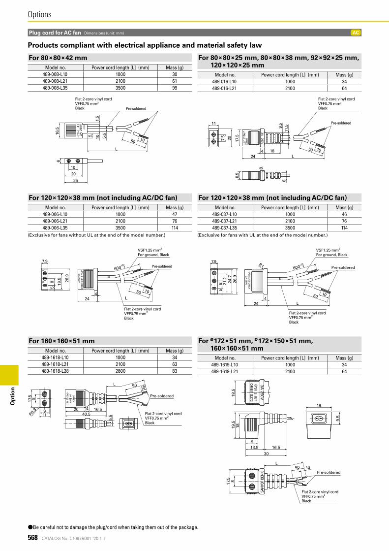
CATALOG No. C1097B001 '20.1.IT
AC
568
OptionsO
pti
on
Pre-soldered
Flat 2-core vinyl cordVFF0.75 mm2
Black
5 101.
5
5.616
.56
10
20
25
50 10
L
<PS
>E
JET
OR
IEX
3A 2
50V Pre-soldered
Flat 2-core vinyl cordVFF0.75 mm2
Black
50424
10
9.5
18
8
6
7.5
11.5
113A
250V
ORIEX
<PS>E JET
L
20
8.9
17.5
50424
58
19.5 26
.9
7.9
10
3A 250V
ING
G
<PS> E JET O
RIEX
L
Pre-soldered
VSF1.25 mm2
For ground, Black
Flat 2-core vinyl cordVFF0.75 mm2
Black
600 0+20
50 10
24
R1
58 24
.726
.9
7.9
21.2
3A 250V
ING
G
600 0+20
<PS>E JET O
RIEX
4
Pre-soldered
L
VSF1.25 mm2
For ground, Black
Flat 2-core vinyl cordVFF0.75 mm2
Black
50
40.520
5.5
OR
IEX
3A 250V
〈P
S〉 E JE
T
16.59
R0.3
817.5
11
4
10
Pre-soldered
L
Flat 2-core vinyl cordVFF0.75 mm2
Black
817.5
〈P
S〉 E JE
TO
RIE
X S
272
3A 250V
19
9.5
30
16.513.59
1819.5
18.5
50 10Pre-soldered
L
Flat 2-core vinyl cordVFF0.75 mm2
Black
Plug cord for AC fan Dimensions (unit: mm)
Products compliant with electrical appliance and material safety law
●Be careful not to damage the plug/cord when taking them out of the package.
For 80×80×42 mmModel no. Power cord length [L] (mm) Mass (g)
489-008-L10 1000 30489-008-L21 2100 61489-008-L35 3500 99
For 160×160×51 mmModel no. Power cord length [L] (mm) Mass (g)
489-1618-L10 1000 34489-1618-L21 2100 63489-1618-L28 2800 83
For 120×120×38 mm (not including AC/DC fan)Model no. Power cord length [L] (mm) Mass (g)
489-006-L10 1000 47489-006-L21 2100 76489-006-L35 3500 114
(Exclusive for fans without UL at the end of the model number.)
For 80×80×25 mm, 80×80×38 mm, 92×92×25 mm, 120×120×25 mm
Model no. Power cord length [L] (mm) Mass (g)489-016-L10 1000 34489-016-L21 2100 64
For ø172×51 mm, ø172×150×51 mm, 160×160×51 mm
Model no. Power cord length [L] (mm) Mass (g)489-1619-L10 1000 34489-1619-L21 2100 64
For 120×120×38 mm (not including AC/DC fan)Model no. Power cord length [L] (mm) Mass (g)
489-037-L10 1000 46489-037-L21 2100 76489-037-L35 3500 114
(Exclusive for fans with UL at the end of the model number.)
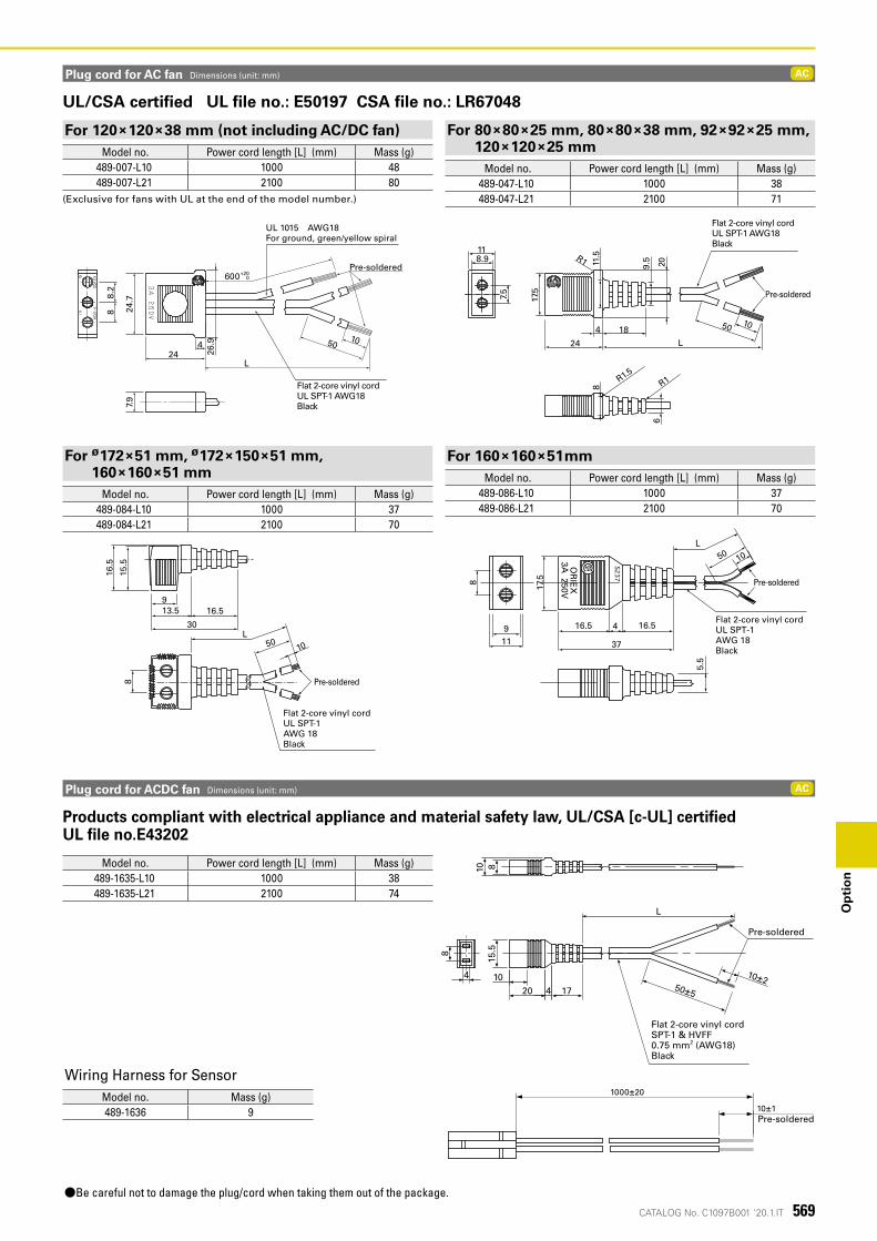
CATALOG No. C1097B001 '20.1.IT
AC
AC
先端予備はんだ
50±5
10±2
L
20 4 1710
15.5
810
8
4
平形2芯ビニールコードSPT-1 & HVFF 0.75 mm2 (AWG18) 黒
1000±20
10±1
569
Op
tio
n
600
5010
+200
L
8
4
8.2
24.7
7.9
26.9
24
Flat 2-core vinyl cordUL SPT-1 AWG18Black
UL 1015 AWG18For ground, green/yellow spiral
Pre-soldered
Plug cord for AC fan Dimensions (unit: mm)
UL/CSA certified UL file no.: E50197 CSA file no.: LR67048
L18
9.5
6
R1R1.5
811
.5
118.9
7.5
R1
4
24
1050
17.5
20
Pre-soldered
Flat 2-core vinyl cordUL SPT-1 AWG18Black
8
16.5
15.5
L50
10
913.5 16.5
30
Flat 2-core vinyl cordUL SPT-1AWG 18Black
Pre-soldered
5.5
8 17.5
50 10
119
37
16.5 4 16.5
OR
IEX
3A 250V
L
Flat 2-core vinyl cordUL SPT-1AWG 18Black
Pre-soldered
Products compliant with electrical appliance and material safety law, UL/CSA [c-UL] certified UL file no.E43202
Plug cord for ACDC fan Dimensions (unit: mm)
●Be careful not to damage the plug/cord when taking them out of the package.
Pre-soldered
Pre-soldered
Flat 2-core vinyl cordSPT-1 & HVFF 0.75 mm2 (AWG18) Black
For 120×120×38 mm (not including AC/DC fan)Model no. Power cord length [L] (mm) Mass (g)
489-007-L10 1000 48489-007-L21 2100 80
(Exclusive for fans with UL at the end of the model number.)
For ø172×51 mm, ø172×150×51 mm, 160×160×51 mm
Model no. Power cord length [L] (mm) Mass (g)489-084-L10 1000 37489-084-L21 2100 70
Model no. Power cord length [L] (mm) Mass (g)489-1635-L10 1000 38489-1635-L21 2100 74
For 80×80×25 mm, 80×80×38 mm, 92×92×25 mm, 120×120×25 mm
Model no. Power cord length [L] (mm) Mass (g)489-047-L10 1000 38489-047-L21 2100 71
For 160×160×51mmModel no. Power cord length [L] (mm) Mass (g)
489-086-L10 1000 37489-086-L21 2100 70
Wiring Harness for SensorModel no. Mass (g)489-1636 9
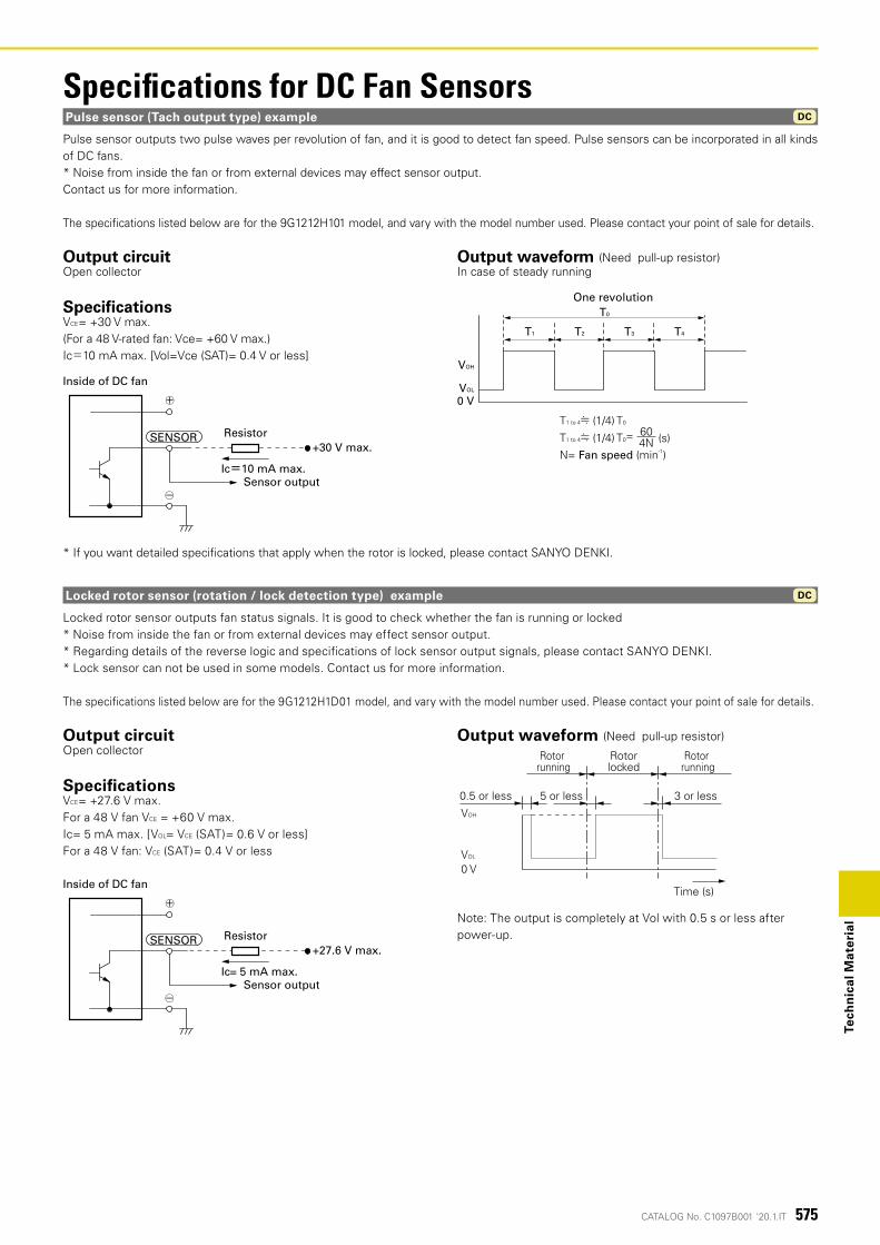
575CATALOG No. C1097B001 '20.1.IT
DC
Tech
nic
al M
ater
ial
Pulse sensor outputs two pulse waves per revolution of fan, and it is good to detect fan speed. Pulse sensors can be incorporated in all kinds of DC fans. * Noise from inside the fan or from external devices may effect sensor output.Contact us for more information.
The speci�cations listed below are for the 9G1212H101 model, and vary with the model number used. Please contact your point of sale for details.
* If you want detailed speci�cations that apply when the rotor is locked, please contact SANYO DENKI.
Output circuitOpen collector
SpecificationsVCE= +30 V max.(For a 48 V-rated fan: Vce= +60 V max.)Ic=10 mA max. [Vol=Vce (SAT)= 0.4 V or less]
Output waveform (Need pull-up resistor)In case of steady running
DCPulse sensor (Tach output type) example
Specifications for DC Fan Sensors
(s)604N
T1 to 4≒ (1/4) T0
T1 to 4≒ (1/4) T0=
N= Fan speed (min-1)
T0
One revolution
T1
0 VVOL
VOH
T2 T3 T4
Inside of DC fan
○-
○+
Ic=10 mA max.
+30 V max.
Sensor output
ResistorSENSOR
Locked rotor sensor outputs fan status signals. It is good to check whether the fan is running or locked* Noise from inside the fan or from external devices may effect sensor output.* Regarding details of the reverse logic and speci�cations of lock sensor output signals, please contact SANYO DENKI.* Lock sensor can not be used in some models. Contact us for more information.
The speci�cations listed below are for the 9G1212H1D01 model, and vary with the model number used. Please contact your point of sale for details.
Output circuit Open collector
SpecificationsVCE= +27.6 V max.For a 48 V fan VCE = +60 V max.Ic= 5 mA max. [VOL= VCE (SAT)= 0.6 V or less]For a 48 V fan: VCE (SAT)= 0.4 V or less
Output waveform (Need pull-up resistor)
Note: The output is completely at Vol with 0.5 s or less after power-up.
Locked rotor sensor (rotation / lock detection type) example
Inside of DC fan
○-
○+
Ic= 5 mA max.
+27.6 V max.
Sensor output
ResistorSENSOR
VOH
VOL
0 V
Time (s)
5 or less0.5 or less 3 or less
Rotor running
Rotorlocked
Rotor running
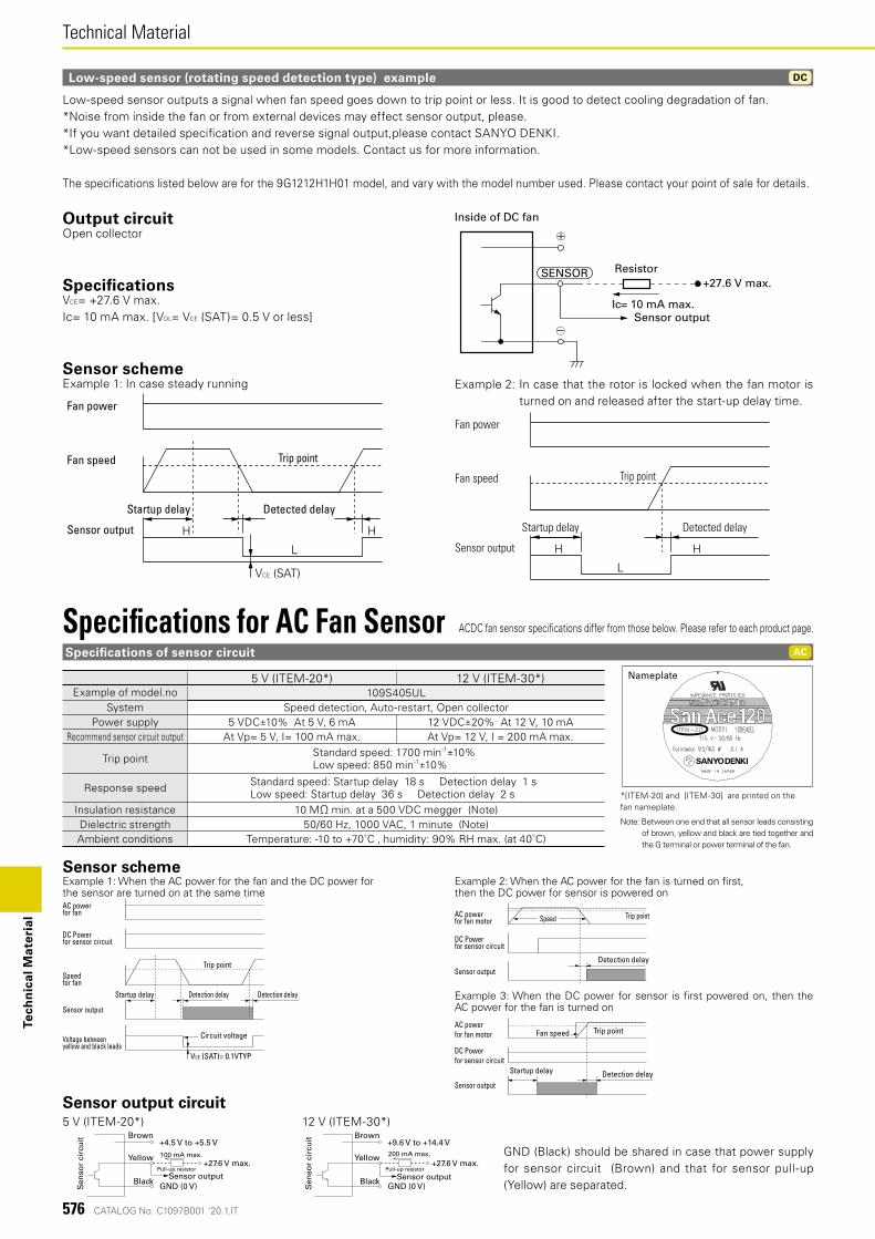
576 CATALOG No. C1097B001 '20.1.IT
DC
Technical MaterialTe
chn
ical
Mat
eria
l
Low-speed sensor outputs a signal when fan speed goes down to trip point or less. It is good to detect cooling degradation of fan. *Noise from inside the fan or from external devices may effect sensor output, please.*If you want detailed speci�cation and reverse signal output,please contact SANYO DENKI. *Low-speed sensors can not be used in some models. Contact us for more information.
The speci�cations listed below are for the 9G1212H1H01 model, and vary with the model number used. Please contact your point of sale for details.
Output circuitOpen collector
SpecificationsVCE= +27.6 V max.Ic= 10 mA max. [VOL= VCE (SAT)= 0.5 V or less]
Sensor schemeExample 1: In case steady running
Low-speed sensor (rotating speed detection type) example
Inside of DC fan
○-
○+
Ic= 10 mA max.
+27.6 V max.
Sensor output
ResistorSENSOR
H H
L
VCE (SAT)
Fan power
Fan speed Trip point
Sensor output
Startup delay Detected delay
Example 2: In case that the rotor is locked when the fan motor is turned on and released after the start-up delay time.
H H
L
Fan power
Fan speed Trip point
Sensor output
Startup delay Detected delay
GND (Black) should be shared in case that power supply for sensor circuit (Brown) and that for sensor pull-up (Yellow) are separated.
Specifications of sensor circuit
Specifications for AC Fan Sensor ACDC fan sensor speci�cations differ from those below. Please refer to each product page.
5 V (ITEM-20*) 12 V (ITEM-30*)Example of model.no 109S405UL
System Speed detection, Auto-restart, Open collectorPower supply 5 VDC±10% At 5 V, 6 mA 12 VDC±20% At 12 V, 10 mA
Recommend sensor circuit output At Vp= 5 V, I= 100 mA max. At Vp= 12 V, I = 200 mA max.
Trip point Standard speed: 1700 min-1±10%Low speed: 850 min-1±10%
Response speed Standard speed: Startup delay 18 s Detection delay 1 sLow speed: Startup delay 36 s Detection delay 2 s
Insulation resistance 10 MΩ min. at a 500 VDC megger (Note)Dielectric strength 50/60 Hz, 1000 VAC, 1 minute (Note)Ambient conditions Temperature: -10 to +70˚C , humidity: 90% RH max. (at 40˚C)
Note: Between one end that all sensor leads consisting of brown, yellow and black are tied together and the G terminal or power terminal of the fan.
Sensor schemeExample 1: When the AC power for the fan and the DC power forthe sensor are turned on at the same time
DC Power for sensor circuit
Speed for fan
Trip point
Sensor output
AC power for fan
Startup delay Detection delay Detection delay
Circuit voltage
VCE (SAT)= 0.1VTYP
Voltage between yellow and black leads
Example 2: When the AC power for the fan is turned on �rst,then the DC power for sensor is powered on
DC Powerfor sensor circuit
Speed Trip point
Sensor output
AC power for fan motor
Detection delay
Example 3: When the DC power for sensor is �rst powered on, then the AC power for the fan is turned on
DC Powerfor sensor circuit
Fan speed Trip point
Sensor output
AC power for fan motor
Detection delayStartup delay
+4.5 V to +5.5 V
GND (0 V)Sen
sor
circ
uit Brown
Yellow
Black
+27.6 V max.100 mA max.
Sensor outputPull-up resistor
+9.6 V to +14.4 V
GND (0 V)Sen
sor
circ
uit Brown
Yellow
Black
+27.6 V max.200 mA max.
Sensor outputPull-up resistor
5 V (ITEM-20*) 12 V (ITEM-30*)
*[ITEM-20] and [ITEM-30] are printed on the fan nameplate.
Nameplate
AC
Sensor output circuit
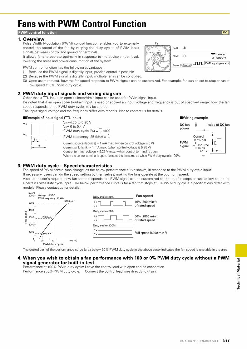
577CATALOG No. C1097B001 '20.1.IT
Tech
nic
al M
ater
ial
Fans with PWM Control FunctionPWM control function DC
1. OverviewPulse Width Modulation (PWM) control function enables you to externally control the speed of the fan by varying the duty cycles of PWM input signals between control and grounding terminals.It allows fans to operate optimally in response to the device's heat level, lowering the noise and power consumption of the system.
PWM control function has the following advantages:(1) Because the PWM signal is digitally input, precise control is possible.(2) Because the PWM signal is digitally input, multiple fans can be controlled.(3) Upon users request, how the fan speed responds to PWM signals can be customized. For example, fan can be set to stop or run at
low speed at 0% PWM duty cycle.
2. PWM duty input signals and wiring diagramOther than a TTL input, an open collector/drain input can be used for PWM signal input.Be noted that if an open collector/drain input is used or applied an input voltage and frequency is out of speci�ed range, how the fan speed responds to the PWM duty cycle may be altered.The input signal voltage and the frequency differ with models. Please contact us for details.
■Wiring example■Example of input signal (TTL input)
Power supply
Fan(Red)
(Black)
(Brown) ControlPWM signal generator
PWM signal
DC fan power
IsourceIsink
Control Terminal
Inside of DC fan
T1
T
VIL
VIHVIH=4.75 to 5.25 VVIL= 0 to 0.4 VPWM duty cycle (%) = T1
T×100
PWM frequency 25 (kHz) = 1T
Current source (Isource) = 1 mA max. (when control voltage is 0 V)Current sink (Isink) = 1 mA max. (when control voltage is 5.25 V)Control terminal voltage = 5.25 V max. (when control terminal is open)When the control terminal is open, fan speed is the same as when PWM duty cycle is 100%.
3. PWM duty cycle – Speed characteristicsFan speed of PWM control fans change, as the below performance curve shows, in response to the PWM duty cycle input.If necessary, users can do the speed setting by themselves, making the fans operate at the optimum speed.Also, upon user's request, how fan speed responds to a PWM signal can be customized so that the fan stops or runs at low speed for a certain PWM duty cycle input. The below performance curve is for a fan that stops at 0% PWM duty cycle. Speci�cations differ with models. Please contact us for details.
100502000
PWM duty cycle
6000
5000
4000
2000
3000
1000
Fan
sp
eed
5000 min-1
2800 min-1
800 min-1
PWM frequency: 25 kHzVoltage: 12 VDC
(min-1)
(%)
Fan speed
Duty cycle=100%
5 V
0 V
Duty cycle=50%
5 V
0 V
Duty cycle=20%
5 V
0 V
Full speed (5000 min-1)
56% (2800 min-1)of rated speed
16% (800 min-1)of rated speed
The dotted part of the performance curve (area below 20% PWM duty cycle in the above case) indicates the fan speed is unstable in the area.
4. When you wish to obtain a fan performance with 100 or 0% PWM duty cycle without a PWM signal generator for built-in test.Performance at 100% PWM duty cycle: Leave the control lead wire open and no connection.Performance at 0% PWM duty cycle: Connect the control lead wire directly to ⊖ pin.
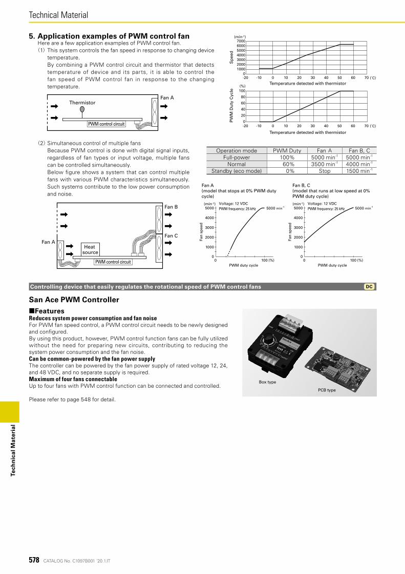
578 CATALOG No. C1097B001 '20.1.IT
Technical MaterialTe
chn
ical
Mat
eria
l
San Ace PWM Controller■FeaturesReduces system power consumption and fan noiseFor PWM fan speed control, a PWM control circuit needs to be newly designed and con�gured.By using this product, however, PWM control function fans can be fully utilized without the need for preparing new circuits, contributing to reducing the system power consumption and the fan noise.Can be common-powered by the fan power supplyThe controller can be powered by the fan power supply of rated voltage 12, 24, and 48 VDC, and no separate supply is required.Maximum of four fans connectableUp to four fans with PWM control function can be connected and controlled.
Please refer to page 548 for detail.
Fan B
Fan CFan A
PWM control circuit
Heat source
10000
5000
4000
2000
3000
1000
PWM duty cycle
Fan A(model that stops at 0% PWM duty cycle)
Fan
sp
eed
5000 min-1PWM frequency: 25 kHzVoltage: 12 VDC
10000
5000
4000
2000
3000
1000
PWM duty cycle
Fan
sp
eed
5000 min-1PWM frequency: 25 kHzVoltage: 12 VDC
(%)
(min-1)
(%)
(min-1)
Fan B, C(model that runs at low speed at 0% PWM duty cycle)
(2) Simultaneous control of multiple fans Because PWM control is done with digital signal inputs,
regardless of fan types or input voltage, multiple fans can be controlled simultaneously.
Below �gure shows a system that can control multiple fans with various PWM characteristics simultaneously. Such systems contribute to the low power consumption and noise.
Operation mode PWM Duty Fan A Fan B, CFull-power 100% 5000 min-1 5000 min-1
Normal 60% 3500 min-1 4000 min-1
Standby (eco mode) 0% Stop 1500 min-1
Controlling device that easily regulates the rotational speed of PWM control fans DC
PCB type
Box type
Fan AThermistor
PWM control circuit
01000200030004000500060007000
-20 -10 0 10 20 30 40 50 60 70
Sp
eed
0
20
40
60
80
100
-20 -10 0 10 20 30 40 50 60 70
PW
M D
uty
Cyc
le
Temperature detected with thermistor
Temperature detected with thermistor(%)
(˚C)
(˚C)
(min-1)5. Application examples of PWM control fanHere are a few application examples of PWM control fan.(1) This system controls the fan speed in response to changing device
temperature. By combining a PWM control circuit and thermistor that detects
temperature of device and its parts, it is able to control the fan speed of PWM control fan in response to the changing temperature.
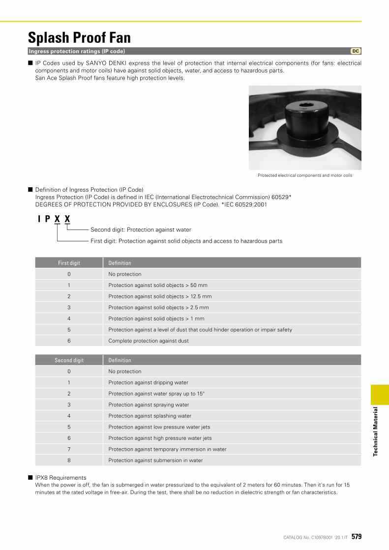
579CATALOG No. C1097B001 '20.1.IT
DC
Tech
nic
al M
ater
ial
Ingress protection ratings (IP code)
■ IP Codes used by SANYO DENKI express the level of protection that internal electrical components (for fans: electrical components and motor coils) have against solid objects, water, and access to hazardous parts.
San Ace Splash Proof fans feature high protection levels.
■ De�nition of Ingress Protection (IP Code) Ingress Protection (IP Code) is de�ned in IEC (International Electrotechnical Commission) 60529* DEGREES OF PROTECTION PROVIDED BY ENCLOSURES (IP Code). *IEC 60529:2001
First digit Definition
0 No protection
1 Protection against solid objects > 50 mm
2 Protection against solid objects > 12.5 mm
3 Protection against solid objects > 2.5 mm
4 Protection against solid objects > 1 mm
5 Protection against a level of dust that could hinder operation or impair safety
6 Complete protection against dust
Second digit Definition
0 No protection
1 Protection against dripping water
2 Protection against water spray up to 15°
3 Protection against spraying water
4 Protection against splashing water
5 Protection against low pressure water jets
6 Protection against high pressure water jets
7 Protection against temporary immersion in water
8 Protection against submersion in water
■ IPX8 Requirements When the power is off, the fan is submerged in water pressurized to the equivalent of 2 meters for 60 minutes. Then it's run for 15 minutes at the rated voltage in free-air. During the test, there shall be no reduction in dielectric strength or fan characteristics.
I P X XSecond digit: Protection against water
First digit: Protection against solid objects and access to hazardous parts
Protected electrical components and motor coils
Splash Proof Fan
582 CATALOG No. C1097B001 '20.1.IT
Standards and Certi�cationsS
tan
dar
ds
and
Cer
tifi
cati
on
s
Safety StandardsOur products conform to these directives and safety standards. For compliance with standards, see individual product pages.
1. UL ratings (USA)
Underwriters Laboratories Inc. was established by the American Union of Fire Insurance Underwriters. The purpose of UL is to ensure safety of machines, equipment, and materials and protect human lives and property from fire and other accidents. To that end, UL has conducted numerous tests and extensive research and, as a result, set up UL ratings. Any seller of products in any of the majority of the states of the USA must produce their products according to the UL ratings, have them pass UL-specified safety inspections, and have them listed in UL's registration book. Therefore, to export and sell any product in the United States, one must in most cases apply for UL-listing. Additionally, UL is accredited by The Standards Council of Canada (SCC) as both a Certification Organization (CO) and a Testing Organization (TO) and is officially recognized in all provinces and territories throughout Canada. Accordingly, our products can be tested by UL for compliance with Canadian safety standards. Certified products are entitled to display the cUL Mark, which authorizes their use and sale in Canada. If products are deemed to be compliant with both U.S. and Canadian standards, then both the UL Mark and cUL Mark can be displayed or a combination U.S. and Canadian mark (bottom left).Our fans are certified as satisfying all UL 507 requirements.
The Canadian Standards Association (CSA) was set up in response to the advice of the Canadian government. In Canada, the law prohibits the use and sale of any product other than those approved under CSA in terms of safety. CSA has set up CSA standards as inspection procedures and other requirements to ensure product safety. Our products are certified as satisfying the CSA standard C22.2 No. 113.
In the EU territory, the harmonization of industrial standards and safety standards of different countries is under way. The unified standards are called Harmonized Standards. Each of these standards is marked EN above the standard number. EN standards offer the grounds in design and manufacture when one exports a product to the EU territory. In order for a product to receive a safety marking, the product must be found to conform to TÜV, VDE, or other relevant standard. Our products are certified by TÜV Rheinland to meet the requirements of EN 60950-1/EN 62368-1. (San Ace Controller complies with EN 60730-1)
As of April 1, 2001, the Electrical Appliance and Material Control Law has been revised and reenacted as the Electrical Appliance and Material Safety Law.AC fans are classified as ‘Blowers’ under ‘Electric motor-operated appliances’. They are categorized as electrical products other than specific electrical appliances (with the exception of some models) and are required to be labeled to indicate PSE certification.
To distribute their equipment in the EU territory, manufacturers are obligated to give a CE marking as proof that the equipment conforms to related EC directives. Manufacturers use EN standards as criteria of judgment as to whether the equipment satisfies the requirements of specific directives or, in the absence of applicable EN standards, they use IEC standards. Manufacturers then prepare a self-declaration to indicate that the equipment conforms to related directives and apply a CE marking. (Depending on the degree of risk of the equipment, some kinds of equipment are required to receive type tests conducted by certified authorities and, after a type test certificate is obtained, manu-facturers make a self-declaration.) Scope of application of major EC directives Machine directivesThese directives apply to equipment that has a moving part that may injure humans. The directives generally apply to a wide range of machine tools and other industrial machines.EMC directivesThey apply to equipment which may be affected by electromagnetic interference (EMI) or has ele-ctromagnetic susceptibility (EMS).Low-voltage directive This directive applies to equipment that is used in an AC range between 50 and 1000 V and in a DC range between 75 and 1500 V.ErP DirectiveEnergy related Products Directive aims to protect the environment and requires eco-design.RoHS DirectiveThis directive restricts of the use of certain hazardous substances contained in electrical and electronic equipment.Radio Equipment DirectiveThis directive sets requirements that radio and communications equipment should meet.
PSE
5. CE marking
PSE
2. CSA standards (Canada)
3. EN standards (EU members)
PSE
4. Electrical appliance and material safety law
583CATALOG No. C1097B001 '20.1.IT
Sta
nd
ard
s an
d C
erti
fica
tio
ns
Eco-productsEfforts for designing Eco-productsAs for product design, we are carrying out R&D to incorporate the latest energy-saving technologies into our new products. At the same time, we carry out product assessments to evaluate the environmental impact of products at each stage, such as component and material procurement, manufacture, distribution, use, recycling, and disposal.Newly developed products are compared with commercially available and existing products and are certified as Eco-products (Eco-design products) if they satisfy the specified evaluation standards. Eco-products are presented in catalogues and other materials with a LEAF symbol.
Life cycle assessment (LCA)LCA is one of the techniques used to provide a general quantitative measure of levels of environmental impact including global warming that products have through their life cycles. We evaluate the environmental compatibility of a product using this method. Our rate of implementing LCA in our Ecoproducts was 90%.
RoHS Directive ComplianceAll products listed in this catalog conform to the EU RoHS Directive 2011/65/EU and EU 2015/863.These Directives restrict the following ten hazardous substances: cadmium, lead, mercury, tetravalent chromium, PBB, PBDE, DEHP, BBP, DBP, and DIBP.Implementation schedule is as follows:
Products Implementation date
Fans, PWM Controller, San Ace Controller Produced in and after January 2019
Plug cords Shipped in and after October 2018
Finger guards, �lter kits Shipped in and after January 2018
Air�ow Tester Produced in and after July 2019
6. Technical Standard Conformity Certification
The Technical Standard Conformity Certification mark, set by Japanese Ministry of Internal Affairs and Communications, indicates that the product is certified as either or both of the following: specific radio equipment defined in the Radio Act and terminal equipment defined in the Telecommunications Business Act.Our San Ace Controller has built-in Technical Standard Conformity-certified specific radio equipment defined in the Radio Act in Japan.It is also a certified terminal equipment based on the Telecommunications Business Act in Japan.
7. VCCI VCCI is a membership organization in Japan that aims to suppress electromagnetic interference generated from information technology equipment by industry self-regulation. It sets standards for noise, which affects other communications equipment, generated from data-processing equipment. VCCI categorizes information technology equipment in two classes: Class A equipment is used in commercial and industrial areas and Class B equipment is used in residential and adjacent areas.Our San Ace Controller is categorized as Class B information technology equipment.
8. FCC Federal Communications Commission (FCC) is an independent U.S. government agency responsible for implementing and enforcing U.S. communications law and regulations. Obtaining an FCC certification is required to sell communications equipment including radio equipment in the U.S.Our San Ace Controller complies with FCC Part 15 Class B.
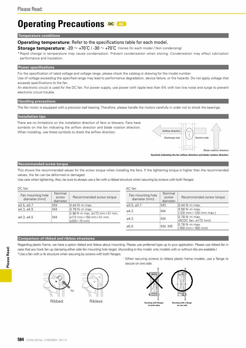
584 CATALOG No. C1097B001 '20.1.IT
Please Read:P
leas
e R
ead
:
DC fan
Fan mounting hole diameter [mm]
Nominal screw
diameterRecommended screw torque
ø3.5, ø3.7 M3 0.44 N・m max.ø4.3, ø4.5 M4 0.78 N・m max.
ø4.3, ø4.5 M40.98 N・m max. (ø172 mm× 51 mm, ø172 mm× 150 mm× 51 mm, ø200 × 70 mm)
AC fan
Fan mounting hole diameter [mm]
Nominal screw
diameterRecommended screw torque
ø3.5, ø3.7 M3 0.44 N・m max.
ø4.3 M4 0.58 N・m max. (120 mm× 120 mm max.)
ø4.3 M4 0.78 N・m max. (ACDC fan, ø172 mm)
ø5.5 M4, M5 0.78 N・m max. (160 mm× 160 mm)
Temperature conditions
Operating temperature: Refer to the specifications table for each model.Storage temperature: -20~ +70˚C / -30~ +70˚C (Varies for each model / Non condensing)
* Rapid change in temperature may cause condensation. Prevent condensation when storing. Condensation may affect lubrication performance and insulation.
Power specifications
For the speci�cation of rated voltage and voltage range, please check the catalog or drawing for the model number.Use of voltage exceeding the speci�ed range may lead to performance degradation, device failure, or �re hazards. Do not apply voltage that exceeds speci�cations to the fan.An electronic circuit is used for the DC fan. For power supply, use power with ripple less than 5% with low line noise and surge to prevent electronic circuit trouble.
Handling precautions
The fan motor is equipped with a precision ball bearing. Therefore, please handle the motors carefully in order not to shock the bearings.
Installation tips
There are no limitations on the installation direction of fans or blowers. Fans have symbols on the fan indicating the airflow direction and blade rotation direction. When installing, use these symbols to check the air�ow direction. Air�ow direction
Symbols indicating the fan air�ow direction and blade rotation direction
Blade rotation direction
Suction sideDischarge side
Operating Precautions DC AC
Rib
Ribbed Ribless Securing with flanges on both sides
Securing with a flange on one side
Comparison of ribbed and ribless structures
Regarding plastic frame, we have a option ribbed and ribless about mounting. Please use preferred type up to your application. Please use ribbed fan in case that you hook fan up clamping either side fan mounting hole target. (According to the model, only models with or without ribs are available.)*Use a fan with a rib structure when securing by screws with both �anges.
・ When securing screws to ribless plastic frame models, use a flange to secure on one side.
Recommended screw torque
This shows the recommended values for the screw torque when installing the fans. If the tightening torque is higher than the recommended values, the fan can be deformed or damaged. Use care when tightening. Also, be sure to always use a fan with a ribbed structure when securing by screws with both �anges.
586 CATALOG No. C1097B001 '20.1.IT
Please Read:P
leas
e R
ead
:
・ To ensure that this product is used safely, be sure that you read and understand the following precautions fully and use the product only as directed.
・ Be sure to read the Safety Precautions carefully before installing, connecting, operating, maintaining, or inspecting this product. Follow all the precautions and directions given here.
・ This product has been designed and manufactured for use as a device to be used in general industrial machinery, and may not be used as a standalone product.
・ The product of our company (hereinafter called the product) falls into the category of the products speci�ed in the Attached List 1, Item 16 (Class 84, Item 14) of the Export Trade Control Ordinance. To export the product as an individual part or to export a product into which the product is assembled, the “Informing Requirements” and “Objective Requirements” that the Ministry of Economy, Trade and Industry of Japan established based on the “Catch-all Controls” must be studied for applicability. Accordingly, appropriate export formalities must be performed.
・ When disposing the product, treat it as industrial waste. Please contact your local government of�ce for further details about disposal.
To prevent any possible bodily injury or damage to property or equipment, the following precautions for ensuring safety are displayed according to the following two ranks of importance:
Danger Handling or using the product improperly and in disregard of the instructions with this mark may result in serious bodily injury or death.
Caution Handling or using the product improperly and in disregard of the instructions with this mark may result in bodily injury or physical damage.
Note: Items marked ‘Caution’ may also result in serious bodily injury or death in some circumstances. Always follow the instructions the same as for items marked ‘Danger.’
Descriptions of the precautions to be taken to ensure safety are given below.
Danger・ When using the product in the following environments, use it at your own discretion only after deploying suf�cient safety measures and making prior evaluations.
Equipment such as medical equipment related to human life, facilities that have serious social and public effects, or environments with vibrations such as in automobiles or ships.
・ Ensure that wiring has been correctly done. Failure to do so may result in �re, burns, or electrical shock.・ If there are any grounding taps or wires, ground them securely. There is danger of electric shock.・ Never use in explosive atmospheres, as doing so might result in �res, burns, or bodily injury. Otherwise, it may result in �re, burns, bodily injury, or electrical shock.・ Do not operate the product when electronic components are exposed. There is danger of electric shock.・ Never allow any persons or objects to approach or come into contact with the rotor while in operation, as doing so might result in damage or personal injury.・ Turn off the power and stop using the product immediately if you notice any sparks, smoke, odd odors, sounds, or anything unusual during operation. There is danger of
electrical shock, �res, or bodily injury.・ Never allow the product to fall, topple over, or otherwise be subjected to excessive shocks when moving it, as doing so might result in product breakdown or substandard
operation.・ The product should be handled only by personnel with suf�cient training and knowledge and under the responsibility of the end user.・ Never attempt to disassemble or alter this product in any way. There is danger of electrical shock, �res, or bodily injury.
CautionHandling・ Installation, placement, connections, wiring, or relocation of the product should be performed by knowledgeable or correctly licensed personnel. Never perform such work
while the product is on, as this might lead to injury, electrical shock, burns, or �re.・ Do not use the fan if it is not �xed, nor while held in hand.・ Never allow yourself to come into contact with the ends of wires or plugs when measuring insulation resistance or dielectric strength voltage. There is danger of electric
shock.・ Never attempt to disassemble or alter this product in any way. Doing so may invalidate any warranties concerning the functions or performance of the product, and may
also result in �re, burns, bodily injury, or electrical shock.
Cautions for operation・ Give proper consideration to the device for its protection in case the fan stops during operation.・ Never use the product at voltages, temperatures, or any other settings which exceed those given in the product speci�cations. This might result in substandard operation,
breakdown, �re, bodily injury, or electrical shock.・ The fan may fail to operate properly if there is insuf�cient power capacity, because a starting current several times larger than the rated current will �ow at the moment
voltage is supplied to the fan. Be sure to inquire about starting current levels for individual models.・ Do not control the speed of the fan by changing power voltage using PWM. It may cause fan failure.・ Devices with multiple fans may encounter internal interference. In this case, all fans should be turned on at the same time. Starting a fan while it is being blown on by
another fan may result in fan failure or malfunction. Also, use at your own risk after pre-evaluating the effect of interference on each fan.・ Never insert or remove any lead wires, plug cords or connectors while the power is turned on. Turn off the fan then, while holding the frame, insert or remove plugs or
connectors. Failure to do so might result in damage or electrical shock.・ Do not remove the lead wire of the fan from the frame hook. Doing so may scratch and damage the surface of the lead wire.・ Do not remove the nameplate. There is danger of electrical shock or failure.・ Do not push the nameplate of the fan with strong force. The nameplate may break or come in contact with the shaft.・ The product might become damaged if foreign objects or external forces interfere with normal fan operation.・ Do not implement ON-OFF on the negative power supply line. That might damage the fan.
Safety Precautions DC AC
587CATALOG No. C1097B001 '20.1.IT
Ple
ase
Rea
d:
Installation・ When �xing this product into place, be sure to take the product's weight, vibrations generated during operation, and all other relevant factors into consideration. Failure
to do so may result in the product or its parts falling, resulting in bodily injury or device failure.・ Be sure to check the installation direction (i.e., the fan), as failing to do so might result in bodily injury or mechanical breakdown.・ To ensure that the product operates properly, allow spaces for ventilation and take necessary steps to prevent the entry of foreign objects. Failure to do so might result in
bodily injury or mechanical breakdown.・ When �xing the fan with screws, make sure the screw and sheet metal have not deformed the frame of the fan before operation. If the frame of the fan is deformed,
mechanical failure may occur or speci�ed performance may not be achieved.・ When �xing the fan with screws, ensure the screwing torque. If the screwing torque exceeds the recommended torque, the fan frame may be deformed or damaged. Use
a ribbed frame when using screws to af�x fans with plastic frames. To prevent loose screws, use plain washers or spring lock washers. For the screwing torque of each fan type, contact SANYO DENKI or a SANYO DENKI distributor.
・ When �xing the fan with self-tapping screws, the fan frame may be damaged.・ When excessive shock is applied to the fan, the impeller may protrude from the surface of the fan frame. Make sure that the impeller does not touch covers, such as
�nger guards or mounting plates.・ Do not subject fans to excessive shock to avoid fan failure and performance deterioration.・ Pulling or pinching lead wires could result in damage to the wire; avoid placing excessive stress on wires. The device should be installed so that the lead wires do not
come into contact with the rotor or blades. Failure to do so might result in damage or electrical shock.・ Take proper precautions against static electricity when making electrical connections. Failure to do so might cause the breakdown of the fan or device.・ Install a �nger guard or other cover if there is any danger of �ngers, hands, or objects coming into contact with the rotor or blades. Failure to do so might result in bodily
injury or mechanical breakdown.・ Install �nger guards, �lters, and plates in the correct position while avoiding touching the rotor blade. Avoiding this will prevent device failure. Please use only genuine
SANYO DENKI �nger guards and �lter kits.・ Make electrical connections properly. If not there is a possibility that the device might break, or that the product might malfunction, breakdown, or have degraded
performance.
Installation of Centrifugal Fan・ Use screws to af�x the fan. For screw size of each fan type, refer to drawing or catalog.・ Do not use screws whose length exceeds the depth of the mounting screws. If the screw hole is damaged it may not be possible to affix the fan.
For screw size of each fan type, refer to drawing or catalog.・ When �xing the fan with screws, ensure the screwing torque. If the screwing torque exceeds the recommended torque, the screw hole may be deformed or damaged. To
prevent loose screws, use plain washers or spring lock washers. For the screwing torque of each fan type, contact SANYO DENKI or a SANYO DENKI distributor.・ Install the inlet nozzle, �nger guard, and plate to the fan in the correct position while avoiding touching the rotor blade. Avoiding this will prevent device failure. Please
use only genuine SANYO DENKI inlet nozzles.
Operating environment・ Avoid using or storing the product in the following areas and environments. There is the possibility that a �re may occur, the product may malfunction, or its performance
may deteriorate. Flammable or corrosive gas atmospheres, in places where water or oil splashes (excluding to Splash Proof or Oil Proof Fans), in places where there is much dust or
humidity, in places where condensation occurs, in places where the product is exposed to radioactive rays or is in direct sunlight, in places where a salty sea breeze blows or seawater splashes, or in an environment where the product may be contaminated by such corrosive materials as sulfurous water, sulfurous volcanic ash, organic solvents, acidic chemicals, alkali chemicals, etc., or such hazardous substances as nuclear fuel materials, etc.
・ Avoid using or storing the product in the following areas and environments. Doing so might result in product breakdown or substandard operation. Environments where it could be constantly exposed to vibrations, strong shocks, centrifugal force, acceleration (excluding G Proof Fans), magnetic or electromagnetic noise, areas in which the electromagnetic noise overlaps into power voltage, or areas subjected to rapid environmental �uctuations (temperature, humidity, etc.)
Maintenance・ Maintenance and inspections should always be performed by personnel with suf�cient training and knowledge. Otherwise, it may result in �re, burns, bodily injury, or
electrical shock.・ Never perform any maintenance or inspections while the product is in operation. Also note that the blades continue to rotate for some time immediately after operation
ceases. Always con�rm that all rotating parts have come to a stop before beginning work. Otherwise, it may result in bodily injury.・ Never use gasoline, paint thinner, benzene, or other organic solvents to clean the product, as this could result in deformation or substandard operation.
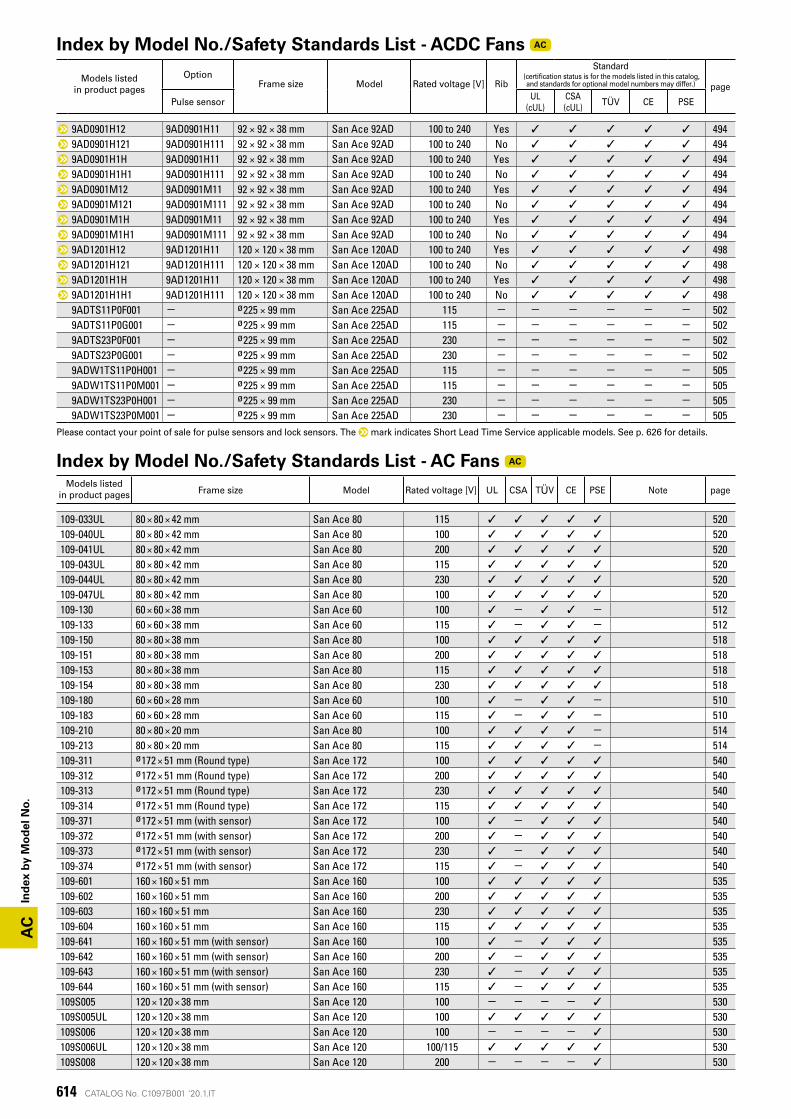
AC
CATALOG No. C1097B001 '20.1.IT614
Ind
ex b
y M
od
el N
o.
Index by Model No./Safety Standards List - ACDC Fans AC
Models listedin product pages
OptionFrame size Model Rated voltage [V] Rib
Standard (certification status is for the models listed in this catalog,
and standards for optional model numbers may differ.) page
Pulse sensorUL
(cUL)CSA (cUL)
TÜV CE PSE
9AD0901H12 9AD0901H11 92 × 92 × 38 mm San Ace 92AD 100 to 240 Yes ✓ ✓ ✓ ✓ ✓ 4949AD0901H121 9AD0901H111 92 × 92 × 38 mm San Ace 92AD 100 to 240 No ✓ ✓ ✓ ✓ ✓ 4949AD0901H1H 9AD0901H11 92 × 92 × 38 mm San Ace 92AD 100 to 240 Yes ✓ ✓ ✓ ✓ ✓ 4949AD0901H1H1 9AD0901H111 92 × 92 × 38 mm San Ace 92AD 100 to 240 No ✓ ✓ ✓ ✓ ✓ 4949AD0901M12 9AD0901M11 92 × 92 × 38 mm San Ace 92AD 100 to 240 Yes ✓ ✓ ✓ ✓ ✓ 4949AD0901M121 9AD0901M111 92 × 92 × 38 mm San Ace 92AD 100 to 240 No ✓ ✓ ✓ ✓ ✓ 4949AD0901M1H 9AD0901M11 92 × 92 × 38 mm San Ace 92AD 100 to 240 Yes ✓ ✓ ✓ ✓ ✓ 4949AD0901M1H1 9AD0901M111 92 × 92 × 38 mm San Ace 92AD 100 to 240 No ✓ ✓ ✓ ✓ ✓ 4949AD1201H12 9AD1201H11 120 × 120 × 38 mm San Ace 120AD 100 to 240 Yes ✓ ✓ ✓ ✓ ✓ 4989AD1201H121 9AD1201H111 120 × 120 × 38 mm San Ace 120AD 100 to 240 No ✓ ✓ ✓ ✓ ✓ 4989AD1201H1H 9AD1201H11 120 × 120 × 38 mm San Ace 120AD 100 to 240 Yes ✓ ✓ ✓ ✓ ✓ 4989AD1201H1H1 9AD1201H111 120 × 120 × 38 mm San Ace 120AD 100 to 240 No ✓ ✓ ✓ ✓ ✓ 4989ADTS11P0F001 - ø225 × 99 mm San Ace 225AD 115 - - - - - - 5029ADTS11P0G001 - ø225 × 99 mm San Ace 225AD 115 - - - - - - 5029ADTS23P0F001 - ø225 × 99 mm San Ace 225AD 230 - - - - - - 5029ADTS23P0G001 - ø225 × 99 mm San Ace 225AD 230 - - - - - - 5029ADW1TS11P0H001 - ø225 × 99 mm San Ace 225AD 115 - - - - - - 5059ADW1TS11P0M001 - ø225 × 99 mm San Ace 225AD 115 - - - - - - 5059ADW1TS23P0H001 - ø225 × 99 mm San Ace 225AD 230 - - - - - - 5059ADW1TS23P0M001 - ø225 × 99 mm San Ace 225AD 230 - - - - - - 505
Please contact your point of sale for pulse sensors and lock sensors. The mark indicates Short Lead Time Service applicable models. See p. 626 for details.
Index by Model No./Safety Standards List - AC Fans AC
Models listedin product pages Frame size Model Rated voltage [V] UL CSA TÜV CE PSE Note page
109-033UL 80 × 80 × 42 mm San Ace 80 115 ✓ ✓ ✓ ✓ ✓ 520109-040UL 80 × 80 × 42 mm San Ace 80 100 ✓ ✓ ✓ ✓ ✓ 520109-041UL 80 × 80 × 42 mm San Ace 80 200 ✓ ✓ ✓ ✓ ✓ 520109-043UL 80 × 80 × 42 mm San Ace 80 115 ✓ ✓ ✓ ✓ ✓ 520109-044UL 80 × 80 × 42 mm San Ace 80 230 ✓ ✓ ✓ ✓ ✓ 520109-047UL 80 × 80 × 42 mm San Ace 80 100 ✓ ✓ ✓ ✓ ✓ 520109-130 60 × 60 × 38 mm San Ace 60 100 ✓ - ✓ ✓ - 512109-133 60 × 60 × 38 mm San Ace 60 115 ✓ - ✓ ✓ - 512109-150 80 × 80 × 38 mm San Ace 80 100 ✓ ✓ ✓ ✓ ✓ 518109-151 80 × 80 × 38 mm San Ace 80 200 ✓ ✓ ✓ ✓ ✓ 518109-153 80 × 80 × 38 mm San Ace 80 115 ✓ ✓ ✓ ✓ ✓ 518109-154 80 × 80 × 38 mm San Ace 80 230 ✓ ✓ ✓ ✓ ✓ 518109-180 60 × 60 × 28 mm San Ace 60 100 ✓ - ✓ ✓ - 510109-183 60 × 60 × 28 mm San Ace 60 115 ✓ - ✓ ✓ - 510109-210 80 × 80 × 20 mm San Ace 80 100 ✓ ✓ ✓ ✓ - 514109-213 80 × 80 × 20 mm San Ace 80 115 ✓ ✓ ✓ ✓ - 514109-311 ø172 × 51 mm (Round type) San Ace 172 100 ✓ ✓ ✓ ✓ ✓ 540109-312 ø172 × 51 mm (Round type) San Ace 172 200 ✓ ✓ ✓ ✓ ✓ 540109-313 ø172 × 51 mm (Round type) San Ace 172 230 ✓ ✓ ✓ ✓ ✓ 540109-314 ø172 × 51 mm (Round type) San Ace 172 115 ✓ ✓ ✓ ✓ ✓ 540109-371 ø172 × 51 mm (with sensor) San Ace 172 100 ✓ - ✓ ✓ ✓ 540109-372 ø172 × 51 mm (with sensor) San Ace 172 200 ✓ - ✓ ✓ ✓ 540109-373 ø172 × 51 mm (with sensor) San Ace 172 230 ✓ - ✓ ✓ ✓ 540109-374 ø172 × 51 mm (with sensor) San Ace 172 115 ✓ - ✓ ✓ ✓ 540109-601 160 × 160 × 51 mm San Ace 160 100 ✓ ✓ ✓ ✓ ✓ 535109-602 160 × 160 × 51 mm San Ace 160 200 ✓ ✓ ✓ ✓ ✓ 535109-603 160 × 160 × 51 mm San Ace 160 230 ✓ ✓ ✓ ✓ ✓ 535109-604 160 × 160 × 51 mm San Ace 160 115 ✓ ✓ ✓ ✓ ✓ 535109-641 160 × 160 × 51 mm (with sensor) San Ace 160 100 ✓ - ✓ ✓ ✓ 535109-642 160 × 160 × 51 mm (with sensor) San Ace 160 200 ✓ - ✓ ✓ ✓ 535109-643 160 × 160 × 51 mm (with sensor) San Ace 160 230 ✓ - ✓ ✓ ✓ 535109-644 160 × 160 × 51 mm (with sensor) San Ace 160 115 ✓ - ✓ ✓ ✓ 535109S005 120 × 120 × 38 mm San Ace 120 100 - - - - ✓ 530109S005UL 120 × 120 × 38 mm San Ace 120 100 ✓ ✓ ✓ ✓ ✓ 530109S006 120 × 120 × 38 mm San Ace 120 100 - - - - ✓ 530109S006UL 120 × 120 × 38 mm San Ace 120 100/115 ✓ ✓ ✓ ✓ ✓ 530109S008 120 × 120 × 38 mm San Ace 120 200 - - - - ✓ 530
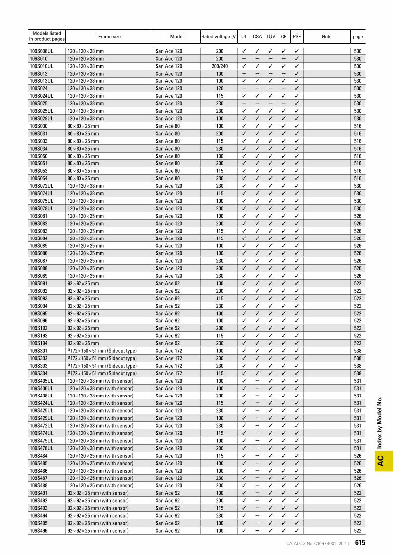
AC
CATALOG No. C1097B001 '20.1.IT 615
Ind
ex b
y M
od
el N
o.
Models listedin product pages Frame size Model Rated voltage [V] UL CSA TÜV CE PSE Note page
109S008UL 120 × 120 × 38 mm San Ace 120 200 ✓ ✓ ✓ ✓ ✓ 530109S010 120 × 120 × 38 mm San Ace 120 200 - - - - ✓ 530109S010UL 120 × 120 × 38 mm San Ace 120 200/240 ✓ ✓ ✓ ✓ ✓ 530109S013 120 × 120 × 38 mm San Ace 120 100 - - - - ✓ 530109S013UL 120 × 120 × 38 mm San Ace 120 100 ✓ ✓ ✓ ✓ ✓ 530109S024 120 × 120 × 38 mm San Ace 120 120 - - - - ✓ 530109S024UL 120 × 120 × 38 mm San Ace 120 115 ✓ ✓ ✓ ✓ ✓ 530109S025 120 × 120 × 38 mm San Ace 120 230 - - - - ✓ 530109S025UL 120 × 120 × 38 mm San Ace 120 230 ✓ ✓ ✓ ✓ ✓ 530109S029UL 120 × 120 × 38 mm San Ace 120 100 ✓ ✓ ✓ ✓ ✓ 530109S030 80 × 80 × 25 mm San Ace 80 100 ✓ ✓ ✓ ✓ ✓ 516109S031 80 × 80 × 25 mm San Ace 80 200 ✓ ✓ ✓ ✓ ✓ 516109S033 80 × 80 × 25 mm San Ace 80 115 ✓ ✓ ✓ ✓ ✓ 516109S034 80 × 80 × 25 mm San Ace 80 230 ✓ ✓ ✓ ✓ ✓ 516109S050 80 × 80 × 25 mm San Ace 80 100 ✓ ✓ ✓ ✓ ✓ 516109S051 80 × 80 × 25 mm San Ace 80 200 ✓ ✓ ✓ ✓ ✓ 516109S053 80 × 80 × 25 mm San Ace 80 115 ✓ ✓ ✓ ✓ ✓ 516109S054 80 × 80 × 25 mm San Ace 80 230 ✓ ✓ ✓ ✓ ✓ 516109S072UL 120 × 120 × 38 mm San Ace 120 230 ✓ ✓ ✓ ✓ ✓ 530109S074UL 120 × 120 × 38 mm San Ace 120 115 ✓ ✓ ✓ ✓ ✓ 530109S075UL 120 × 120 × 38 mm San Ace 120 100 ✓ ✓ ✓ ✓ ✓ 530109S078UL 120 × 120 × 38 mm San Ace 120 200 ✓ ✓ ✓ ✓ ✓ 530109S081 120 × 120 × 25 mm San Ace 120 100 ✓ ✓ ✓ ✓ ✓ 526109S082 120 × 120 × 25 mm San Ace 120 200 ✓ ✓ ✓ ✓ ✓ 526109S083 120 × 120 × 25 mm San Ace 120 115 ✓ ✓ ✓ ✓ ✓ 526109S084 120 × 120 × 25 mm San Ace 120 115 ✓ ✓ ✓ ✓ ✓ 526109S085 120 × 120 × 25 mm San Ace 120 100 ✓ ✓ ✓ ✓ ✓ 526109S086 120 × 120 × 25 mm San Ace 120 100 ✓ ✓ ✓ ✓ ✓ 526109S087 120 × 120 × 25 mm San Ace 120 230 ✓ ✓ ✓ ✓ ✓ 526109S088 120 × 120 × 25 mm San Ace 120 200 ✓ ✓ ✓ ✓ ✓ 526109S089 120 × 120 × 25 mm San Ace 120 230 ✓ ✓ ✓ ✓ ✓ 526109S091 92 × 92 × 25 mm San Ace 92 100 ✓ ✓ ✓ ✓ ✓ 522109S092 92 × 92 × 25 mm San Ace 92 200 ✓ ✓ ✓ ✓ ✓ 522109S093 92 × 92 × 25 mm San Ace 92 115 ✓ ✓ ✓ ✓ ✓ 522109S094 92 × 92 × 25 mm San Ace 92 230 ✓ ✓ ✓ ✓ ✓ 522109S095 92 × 92 × 25 mm San Ace 92 100 ✓ ✓ ✓ ✓ ✓ 522109S096 92 × 92 × 25 mm San Ace 92 100 ✓ ✓ ✓ ✓ ✓ 522109S192 92 × 92 × 25 mm San Ace 92 200 ✓ ✓ ✓ ✓ ✓ 522109S193 92 × 92 × 25 mm San Ace 92 115 ✓ ✓ ✓ ✓ ✓ 522109S194 92 × 92 × 25 mm San Ace 92 230 ✓ ✓ ✓ ✓ ✓ 522109S301 ø172 × 150 × 51 mm (Sidecut type) San Ace 172 100 ✓ ✓ ✓ ✓ ✓ 538109S302 ø172 × 150 × 51 mm (Sidecut type) San Ace 172 200 ✓ ✓ ✓ ✓ ✓ 538109S303 ø172 × 150 × 51 mm (Sidecut type) San Ace 172 230 ✓ ✓ ✓ ✓ ✓ 538109S304 ø172 × 150 × 51 mm (Sidecut type) San Ace 172 115 ✓ ✓ ✓ ✓ ✓ 538109S405UL 120 × 120 × 38 mm (with sensor) San Ace 120 100 ✓ - ✓ ✓ ✓ 531109S406UL 120 × 120 × 38 mm (with sensor) San Ace 120 100 ✓ - ✓ ✓ ✓ 531109S408UL 120 × 120 × 38 mm (with sensor) San Ace 120 200 ✓ - ✓ ✓ ✓ 531109S424UL 120 × 120 × 38 mm (with sensor) San Ace 120 115 ✓ - ✓ ✓ ✓ 531109S425UL 120 × 120 × 38 mm (with sensor) San Ace 120 230 ✓ - ✓ ✓ ✓ 531109S429UL 120 × 120 × 38 mm (with sensor) San Ace 120 100 ✓ - ✓ ✓ ✓ 531109S472UL 120 × 120 × 38 mm (with sensor) San Ace 120 230 ✓ - ✓ ✓ ✓ 531109S474UL 120 × 120 × 38 mm (with sensor) San Ace 120 115 ✓ - ✓ ✓ ✓ 531109S475UL 120 × 120 × 38 mm (with sensor) San Ace 120 100 ✓ - ✓ ✓ ✓ 531109S478UL 120 × 120 × 38 mm (with sensor) San Ace 120 200 ✓ - ✓ ✓ ✓ 531109S484 120 × 120 × 25 mm (with sensor) San Ace 120 115 ✓ - ✓ ✓ ✓ 526109S485 120 × 120 × 25 mm (with sensor) San Ace 120 100 ✓ - ✓ ✓ ✓ 526109S486 120 × 120 × 25 mm (with sensor) San Ace 120 100 ✓ - ✓ ✓ ✓ 526109S487 120 × 120 × 25 mm (with sensor) San Ace 120 230 ✓ - ✓ ✓ ✓ 526109S488 120 × 120 × 25 mm (with sensor) San Ace 120 200 ✓ - ✓ ✓ ✓ 526109S491 92 × 92 × 25 mm (with sensor) San Ace 92 100 ✓ - ✓ ✓ ✓ 522109S492 92 × 92 × 25 mm (with sensor) San Ace 92 200 ✓ - ✓ ✓ ✓ 522109S493 92 × 92 × 25 mm (with sensor) San Ace 92 115 ✓ - ✓ ✓ ✓ 522109S494 92 × 92 × 25 mm (with sensor) San Ace 92 230 ✓ - ✓ ✓ ✓ 522109S495 92 × 92 × 25 mm (with sensor) San Ace 92 100 ✓ - ✓ ✓ ✓ 522109S496 92 × 92 × 25 mm (with sensor) San Ace 92 100 ✓ - ✓ ✓ ✓ 522
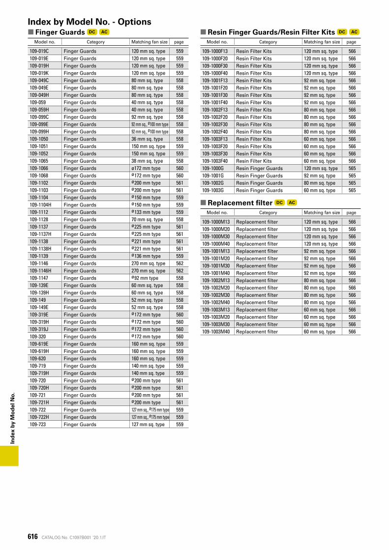
616
Ind
ex b
y M
od
el N
o.
CATALOG No. C1097B001 '20.1.IT
■ Finger Guards DC AC
Model no. Category Matching fan size page
109-019C Finger Guards 120 mm sq. type 559109-019E Finger Guards 120 mm sq. type 559109-019H Finger Guards 120 mm sq. type 559109-019K Finger Guards 120 mm sq. type 559109-049C Finger Guards 80 mm sq. type 558109-049E Finger Guards 80 mm sq. type 558109-049H Finger Guards 80 mm sq. type 558109-059 Finger Guards 40 mm sq. type 558109-059H Finger Guards 40 mm sq. type 558109-099C Finger Guards 92 mm sq. type 558109-099E Finger Guards 92 mm sq., ø100 mm type 558109-099H Finger Guards 92 mm sq., ø100 mm type 558109-1050 Finger Guards 36 mm sq. type 558109-1051 Finger Guards 150 mm sq. type 559109-1052 Finger Guards 150 mm sq. type 559109-1065 Finger Guards 38 mm sq. type 558109-1066 Finger Guards ø172 mm type 560109-1068 Finger Guards ø172 mm type 560109-1102 Finger Guards ø200 mm type 561109-1103 Finger Guards ø200 mm type 561109-1104 Finger Guards ø150 mm type 559109-1104H Finger Guards ø150 mm type 559109-1112 Finger Guards ø133 mm type 559109-1128 Finger Guards 70 mm sq. type 558109-1137 Finger Guards ø225 mm type 561109-1137H Finger Guards ø225 mm type 561109-1138 Finger Guards ø221 mm type 561109-1138H Finger Guards ø221 mm type 561109-1139 Finger Guards ø136 mm type 559109-1146 Finger Guards 270 mm sq. type 562109-1146H Finger Guards 270 mm sq. type 562109-1147 Finger Guards ø92 mm type 558109-139E Finger Guards 60 mm sq. type 558109-139H Finger Guards 60 mm sq. type 558109-149 Finger Guards 52 mm sq. type 558109-149E Finger Guards 52 mm sq. type 558109-319E Finger Guards ø172 mm type 560109-319H Finger Guards ø172 mm type 560109-319J Finger Guards ø172 mm type 560109-320 Finger Guards ø172 mm type 560109-619E Finger Guards 160 mm sq. type 559109-619H Finger Guards 160 mm sq. type 559109-620 Finger Guards 160 mm sq. type 559109-719 Finger Guards 140 mm sq. type 559109-719H Finger Guards 140 mm sq. type 559109-720 Finger Guards ø200 mm type 561109-720H Finger Guards ø200 mm type 561109-721 Finger Guards ø200 mm type 561109-721H Finger Guards ø200 mm type 561109-722 Finger Guards 127 mm sq., ø175 mm type 559109-722H Finger Guards 127 mm sq., ø175 mm type 559109-723 Finger Guards 127 mm sq. type 559
Index by Model No. - Options■ Resin Finger Guards/Resin Filter Kits DC AC
Model no. Category Matching fan size page
109-1000F13 Resin Filter Kits 120 mm sq. type 566109-1000F20 Resin Filter Kits 120 mm sq. type 566109-1000F30 Resin Filter Kits 120 mm sq. type 566109-1000F40 Resin Filter Kits 120 mm sq. type 566109-1001F13 Resin Filter Kits 92 mm sq. type 566109-1001F20 Resin Filter Kits 92 mm sq. type 566109-1001F30 Resin Filter Kits 92 mm sq. type 566109-1001F40 Resin Filter Kits 92 mm sq. type 566109-1002F13 Resin Filter Kits 80 mm sq. type 566109-1002F20 Resin Filter Kits 80 mm sq. type 566109-1002F30 Resin Filter Kits 80 mm sq. type 566109-1002F40 Resin Filter Kits 80 mm sq. type 566109-1003F13 Resin Filter Kits 60 mm sq. type 566109-1003F20 Resin Filter Kits 60 mm sq. type 566109-1003F30 Resin Filter Kits 60 mm sq. type 566109-1003F40 Resin Filter Kits 60 mm sq. type 566109-1000G Resin Finger Guards 120 mm sq. type 565109-1001G Resin Finger Guards 92 mm sq. type 565109-1002G Resin Finger Guards 80 mm sq. type 565109-1003G Resin Finger Guards 60 mm sq. type 565
■ Replacement filter DC AC
Model no. Category Matching fan size page
109-1000M13 Replacement filter 120 mm sq. type 566109-1000M20 Replacement filter 120 mm sq. type 566109-1000M30 Replacement filter 120 mm sq. type 566109-1000M40 Replacement filter 120 mm sq. type 566109-1001M13 Replacement filter 92 mm sq. type 566109-1001M20 Replacement filter 92 mm sq. type 566109-1001M30 Replacement filter 92 mm sq. type 566109-1001M40 Replacement filter 92 mm sq. type 566109-1002M13 Replacement filter 80 mm sq. type 566109-1002M20 Replacement filter 80 mm sq. type 566109-1002M30 Replacement filter 80 mm sq. type 566109-1002M40 Replacement filter 80 mm sq. type 566109-1003M13 Replacement filter 60 mm sq. type 566109-1003M20 Replacement filter 60 mm sq. type 566109-1003M30 Replacement filter 60 mm sq. type 566109-1003M40 Replacement filter 60 mm sq. type 566
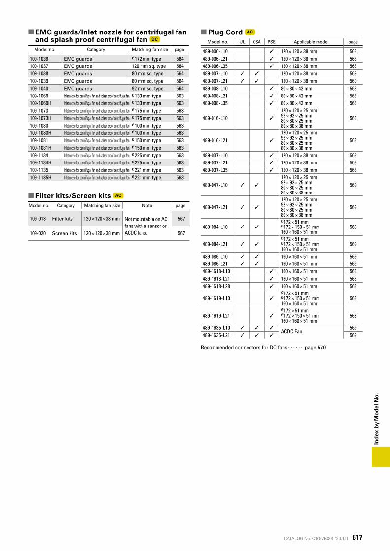
617
Ind
ex b
y M
od
el N
o.
CATALOG No. C1097B001 '20.1.IT
■ EMC guards/Inlet nozzle for centrifugal fan and splash proof centrifugal fan DC
Model no. Category Matching fan size page
109-1036 EMC guards ø172 mm type 564109-1037 EMC guards 120 mm sq. type 564109-1038 EMC guards 80 mm sq. type 564109-1039 EMC guards 80 mm sq. type 564109-1040 EMC guards 92 mm sq. type 564109-1069 Inlet nozzle for centrifugal fan and splash proof centrifugal fan ø133 mm type 563109-1069H Inlet nozzle for centrifugal fan and splash proof centrifugal fan ø133 mm type 563109-1073 Inlet nozzle for centrifugal fan and splash proof centrifugal fan ø175 mm type 563109-1073H Inlet nozzle for centrifugal fan and splash proof centrifugal fan ø175 mm type 563109-1080 Inlet nozzle for centrifugal fan and splash proof centrifugal fan ø100 mm type 563109-1080H Inlet nozzle for centrifugal fan and splash proof centrifugal fan ø100 mm type 563109-1081 Inlet nozzle for centrifugal fan and splash proof centrifugal fan ø150 mm type 563109-1081H Inlet nozzle for centrifugal fan and splash proof centrifugal fan ø150 mm type 563109-1134 Inlet nozzle for centrifugal fan and splash proof centrifugal fan ø225 mm type 563109-1134H Inlet nozzle for centrifugal fan and splash proof centrifugal fan ø225 mm type 563109-1135 Inlet nozzle for centrifugal fan and splash proof centrifugal fan ø221 mm type 563109-1135H Inlet nozzle for centrifugal fan and splash proof centrifugal fan ø221 mm type 563
■ Filter kits/Screen kits AC
Model no. Category Matching fan size Note page
109-018 Filter kits 120 × 120 × 38 mm Not mountable on AC fans with a sensor or ACDC fans.
567
109-020 Screen kits 120 × 120 × 38 mm 567
■ Plug Cord AC
Model no. UL CSA PSE Applicable model page
489-006-L10 ✓ 120 × 120 × 38 mm 568489-006-L21 ✓ 120 × 120 × 38 mm 568489-006-L35 ✓ 120 × 120 × 38 mm 568489-007-L10 ✓ ✓ 120 × 120 × 38 mm 569489-007-L21 ✓ ✓ 120 × 120 × 38 mm 569489-008-L10 ✓ 80 × 80 × 42 mm 568489-008-L21 ✓ 80 × 80 × 42 mm 568489-008-L35 ✓ 80 × 80 × 42 mm 568
489-016-L10 ✓
120 × 120 × 25 mm 92 × 92 × 25 mm 80 × 80 × 25 mm 80 × 80 × 38 mm
568
489-016-L21 ✓
120 × 120 × 25 mm 92 × 92 × 25 mm 80 × 80 × 25 mm 80 × 80 × 38 mm
568
489-037-L10 ✓ 120 × 120 × 38 mm 568489-037-L21 ✓ 120 × 120 × 38 mm 568489-037-L35 ✓ 120 × 120 × 38 mm 568
489-047-L10 ✓ ✓
120 × 120 × 25 mm 92 × 92 × 25 mm 80 × 80 × 25 mm 80 × 80 × 38 mm
569
489-047-L21 ✓ ✓
120 × 120 × 25 mm 92 × 92 × 25 mm 80 × 80 × 25 mm 80 × 80 × 38 mm
569
489-084-L10 ✓ ✓
ø172 × 51 mmø172 × 150 × 51 mm160 × 160 × 51 mm
569
489-084-L21 ✓ ✓
ø172 × 51 mmø172 × 150 × 51 mm160 × 160 × 51 mm
569
489-086-L10 ✓ ✓ 160 × 160 × 51 mm 569489-086-L21 ✓ ✓ 160 × 160 × 51 mm 569489-1618-L10 ✓ 160 × 160 × 51 mm 568489-1618-L21 ✓ 160 × 160 × 51 mm 568489-1618-L28 ✓ 160 × 160 × 51 mm 568
489-1619-L10 ✓
ø172 × 51 mmø172 × 150 × 51 mm160 × 160 × 51 mm
568
489-1619-L21 ✓
ø172 × 51 mmø172 × 150 × 51 mm160 × 160 × 51 mm
568
489-1635-L10 ✓ ✓ ✓ACDC Fan
569489-1635-L21 ✓ ✓ ✓ 569
Recommended connectors for DC fans ‥‥‥ page 570