Embed Size (px)
Citation preview
Accurate SINR Estimation Model for System LevelSimulation of LTE NetworksJosep Colom Ikuno, Stefan Pendl, Michal Simko, Markus Rupp
Institute of TelecommunicationsVienna University of Technology, Austria
Gusshausstrasse 25/389, A-1040 Vienna, AustriaEmail: {jcolom, spendl, msimko, mrupp}@nt.tuwien.ac.at
Web: http://www.nt.tuwien.ac.at/ltesimulator
Abstract—This paper presents an SINR prediction model forLTE systems with the aim of improving the accuracy of physicallayer models used for higher-than-physical-level simulations.This physical layer SINR abstraction for zero-forcing receiverstakes channel estimation errors into account. It allows for thecalculation of the post-equalization receive SINR of an LTEMIMO transmission on a per-layer and subcarrier basis. Thisestimate is further used as input for a link performance modelto accurately predict the receiver throughput. The accuracyof the model is validated by simulations for 2×2 and 4×4MIMO antenna configurations with different levels of spatialmultiplexing employing also the precoding matrices defined inthe LTE standard. Memory requirements and complexity for themodel are quantified as well. The whole simulation environmenttogether with the fully reproducible results of this paper aremade available for download from our homepage.
I. INTRODUCTION
System-level simulations, also referred to as network-levelsimulations, aim at evaluating the performance of networks.Besides being able to test optimizations at the network level,such as cell planning or transmitter placing in cellular net-works, their purpose is also to evaluate whether improvementsat the link level still prove beneficial when taking into ac-count the structure of the whole network and undesired butperformance-limiting effects such as interference [2].
The accuracy of system-level simulations relies on models.These abstract the link-level procedures at low complexity,as full-fledged simulations of all of the procedures performedon every link would result in prohibitively computationally-complex simulations when simulating whole networks. SimpleLTE single-link simulations take in the order of hours [3],mostly due to the complexity of MIMO decoding [4], so setupssuch as a typical wireless cellular network layout consistingof two rings of transmitters each with three sectors are justtoo unpractical to realize by means of link level simulations.
As such, evaluation of link-level improvements at systemlevel is only as accurate as the underlying PHY layer ab-straction model [5], which should be able to capture as manyaspects as possible of the physical layer while still retaininglow complexity. In this paper, we present a post-equalizationSINR estimation model that aims at accurately predictingthe performance of LTE for the purpose of obtaining moreaccurate throughput results in system level simulations. Themodel proposed here addresses the following issues:
(i) Inclusion of channel estimation error in the SINR esti-mation: while generally not taken into account in system levelsimulations, channel estimation error does affect throughputperformance [6], which is in the end the final system perfor-mance measure of our system. This effect is at its strongest atcell edge, and taking it into account is thus necessary if themodel is to be accurate.
(ii) Appropriate modeling of the post-equalization SINR:the SINR, as seen by the channel decoder, depends not onlyon the received interference powers, but also on the receiverstructure. While for SISO systems simpler models such as [7]may suffice, correct modeling of the peformance of the MIMOreceiver and the interference between the several data streamsbeing simultaneously transmitted is necessary if a meaningfulvalidation of link level concepts at system level is expected.
(iii) Results are shown to be accurate with non-i.i.d MIMOchannels, in this case using the Winner II+ channel model [8].
(iv) Although the performance of the Zero-Forcing (ZF)receiver has already been studied [9], this model extends andshows the accuracy of the model to more realistic LTE sce-narios that include Closed Loop Spatial Multiplexing (CLSM)MIMO transmission with precoders chosen from the LTEcodebook [10], and multi-cell scenarios.
The remainder of this paper is organized as follows. InSection II we explain the role of the SINR model in thelink abstraction and formulate its basis. In Section III, thesetup for the validation of the model is presented, as well assimulation results for both a single-cell and a multi-cell setup.Section IV analyzes the memory and complexity requirementsof the model for use in system level simulations. We concludethe paper in Section V.
II. SINR MODEL
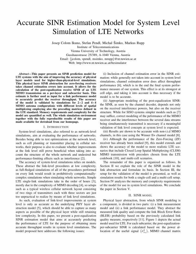
Physical layer abstraction, from which SINR modeling isa component, is divided in two parts: (i) a link measurementmodel and (ii) a link performance model. They abstract themeasured link quality and compute the link Block Error Ratio(BLER) probability based on the previously calculated linkquality measure, respectively [11]. Figure 1 depicts the actualmodel used for LTE. For each subcarrier, the post-equalization-per-subcarrier SINR is calculated based on: the power al-location of the useful signal
(σ2x0
), MIMO channel matrix
link performance model
BLER...
linkmeasurement
model ...
SINR - BLERmapping
(AWGN curves )
SINRcompresion(MIESM)
subcarrier SINR vector
AWGN-equivalent SINR
throughput
Modulation and Coding Scheme
RB allocation
target transmitter
interferers
noise
frequency-domain scheduling
Fig. 1. Physical layer abstraction for LTE system level modeling.
(H0), precoding matrix (W0), the corresponding parametersfor each of the Nint interferers
(σ2xi,Hi,Wi
), thermal noise
power(σ2n
), and frequency allocation, referred to as Resource
Block (RB) allocation in LTE. The SINR is calculated overthe decoded symbols (prior to channel decoding), and thereforecan be used to assess how well the decoding procedure willperform. To allow for a non-multi-dimensional SINR-to-BLERmapping, the set of subcarrier SINRs is non-linearly averagedto a single value in the mutual information domain [12, 13]and then mapped to BLER, from which the throughput can beobtained.
The received signal for one subcarrier can be expressed as:
y = H0W0x0 + n +
Nint∑i=1
HiWixi, (1)
where H0 is the MIMO channel matrix of size numberof transmit antennas (NTX) times number of receive anten-nas (NRX) of the target signal, x0 a vector of ν symbolswhich are being simultaneously transmitted over the channel(ν ≤ min (NTX, NRX)). The precoding matrix W0 maps theν symbols to the NTX transmit antennas. The same notationis used for the Nint interfering signals. Here, n denotes thethermal noise vector of length NRX .
At receiver side, the ZF receiver filter G is expressed as
G =(HH
0 H0
)−1
HH0 , (2)
H0 = H0 + E, (3)
eij ∼ CN(0, σ2
e
), (4)
where G is calculated as the pseudoinverse of the estimatedchannel H0, denoted also in this paper as a generalized inverseH−1
0 . The estimated channel is modeled as the actual channelplus an error matrix whose entries (eij) are modeled ascomplex-normal with mean power σ2
e [9].For convenience, an effective channel matrix H is defined,
which also includes the precoding. Thus:
H = HW, (5)
G = ((H0 + E)W0)−1 (6)
In the model, the mean power of each of the entries of thechannel matrix H are normalized to one, and are assumed to beflat. This assumption is justified by the use of OFDM in LTE,which as long as the cyclic prefix is of long enough, ensuresa flat channel response per subcarrier. In order to accountfor pathloss, the average symbol power σ2
x of each of thetransmitted symbols is scaled with a correspondent pathlossfactor Li, where i = {0, . . . , Nint}
The estimated received symbol vector x0 is obtained as
x0 = Gy, (7)
where the average post-equalization SINR for the k-th symbol(layer), expressed as γk, can be expressed as
γk =σ2x0
ekHMSE ek, (8)
where ek is an all-zero column vector of length ν except fora one on its k-th position. The Mean Squared Error (MSE) ofthe estimated received symbol x0 is then calculated as
MSE = E{
(x0 − x0) (x0 − x0)H}. (9)
Applying a Taylor approximation at E = 0, i.e. valid for asmall variance σ2
e [14], and truncating after the linear terms,the expression in (10) is obtained.
The equation in (10) can then be simplified by excludingthe Tr () parameter [9], obtaining
MSE =(σ2eσ
2x0
+ σ2v
) (HH
0 H0
)−1
(16)
+
Nint∑i=1
[H−1
0
(σ2xiHiWiW
Hi H
Hi
) (H−1
0
)H], (17)
where σxi is the transmit power over all antennas for the i-thuser divided by its pathloss factor Li.
For the purpose of model validation, a fixed value for σ2e
could be used. This setting would, however, not be realistic.As the quality of the channel estimation varies with the qualityof the pilot symbols from which the estimation is done, it istherefore a function of the signal level of the pilots. Adaptingfrom [15], we express the channel estimation error σ2
e as:
σ2e =
ceσ2x0
(σ2n +
Nint∑i=1
σ2xi
), (18)
where a typical value for ce for pedestrian simulations and anLMMSE channel estimator would be 0.0544 [15, 16].
III. SIMULATION RESULTS
The SINR estimation algorithm has been validated in twoscenarios. In the first one, no interfering transmitters werepresent, so the simulation is over an SNR range. In the secondcase, six interferers are placed on a hexagonal grid layout withomnidirectional antennas and the simulation is run over allpoints of the center sector instead of over an SNR range.
In both cases, the model is validated for 2×2 and 4×4antenna configurations. The precoding book specified forLTE [17] allows for transmission of ν spatial layers (i.e.
MSE = E{
(x0 − x0) (x0 − x0)H}
(10)
≈ H−10 E
{EW0x0x
H0 W
H0 E
H
}(H−1
0
)H(11)
+ H−10 E
{nnH
}(H−1
0
)H+ H−1
0 E{EW0H
−10 nnH
(H−1
0
)HWH
0 EH
}(H−1
0
)H(12)
+
Nint∑i=0
[H−1
0 E{Hixix
Hi H
Hi
}(H−1
0
)H+ H−1
0 E{EW0H
−10 Hixixi
HHHi
(H−1
0
)HWHEH
}(H−1
0
)H](13)
=(σ2eσ
2x0
+ σ2v + σ2
vσ2eTr
((HH
0 H0
)−1))(
HH0 H0
)−1
(14)
+
I∑i=1
[H−1
0
(σ2xiHiWiW
Hi H
Hi + σ2
xiσ2eTr
(HiH
Hi
(HH
0 H0
)−1)(
H−10
)H)](15)
simultaneous symbols), where ν ≤ min (NTX, NRX). Themodel is validated for all the possible number of spatial layersfor each antenna configuration. Thus, ν = {1, 2} (2× 2 case)and ν = {1, 2, 3, 4} (4 × 4 case). As the switching betweennumber of layers needs to be performed at run-time, it is notin the scope of validating the accuracy of the model to showthe combined performance of the using a variable number oflayers rather than to evaluate whether the prediction for thechosen one, whichever that may be, is accurate.
In both cases, the channel matrix is obtained from animplementation of the Winner II+ channel model [8], and theprecoding matrix chosen so as to maximize the achievablecapacity [10]. Since no interference coordination is assumed,each interferer is assigned a random precoding matrix from theprecoding codebook (i.e., the channel for which the interferingeNodeB is optimizing its precoding and the actual interferingchannel are assumed uncorrelated). The output of the SINRmodel, when used in the context of system level simulations, isa per-subcarrier SINR estimation. Thus, in order to validate it,the simulations are carried out on a single subcarrier: 15 kHz,as in the most commonly deployed LTE settings [18].
For the modeled case, the average post-equalization SINRfor each channel realization is calculated. For comparison,an actual transmission of symbols is performed, with enoughsymbols per channel realization so as to ensure enough av-eraging. The sum-over-all-streams achievable capacity fromthe actual SINR and the one from the model, calculatedwithout taking into account the maximum rate of the LTEsystem, is then compared. Since the aim is to value theaccuracy of the SINR estimation in in the terms of capacity,the omission of this ceiling is not relevant. On both cases,each simulation point consists of 100 channel realizations, forwhich 50 different symbol/noise realizations are transmitted.For each case, the overall mean achievable capacity for eachchannel realization H0 is calculated as:
Csum =
ν∑i=1
log2
(1 +
1
γi
). (19)
0 5 10 15 20 25 300
2
4
6
8
10
12
14
16
18
SNR [dB]
Ach
ieva
ble
capa
city
[bit/
s/H
z]
1 layer2 layers
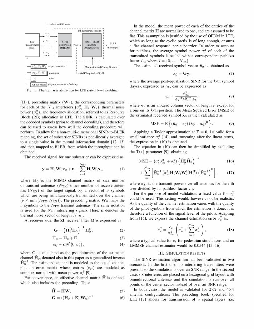
Fig. 2. 2×2 results. Solid line: achievable capacity calculated from the SINRmodel, Dashed line: achievable capacity obtained from the SINR calculatedfrom the actual transmission.
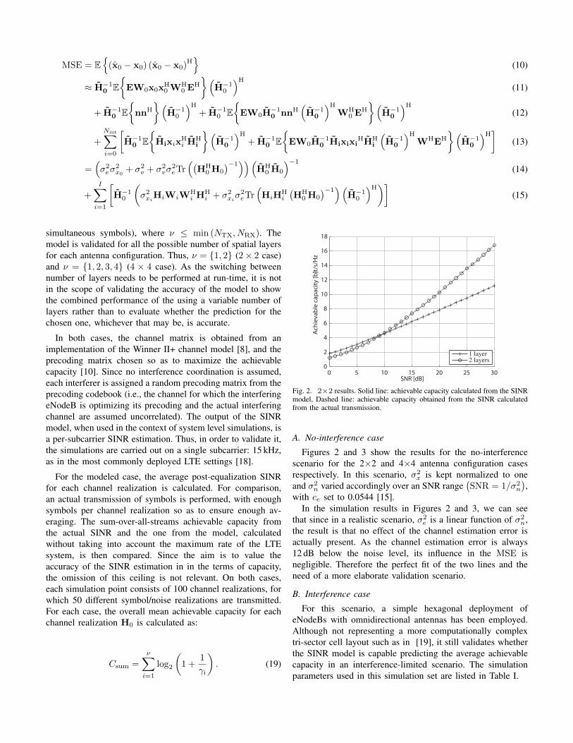
A. No-interference case
Figures 2 and 3 show the results for the no-interferencescenario for the 2×2 and 4×4 antenna configuration casesrespectively. In this scenario, σ2
x is kept normalized to oneand σ2
n varied accordingly over an SNR range(SNR = 1/σ2
n
),
with ce set to 0.0544 [15].In the simulation results in Figures 2 and 3, we can see
that since in a realistic scenario, σ2e is a linear function of σ2
n,the result is that no effect of the channel estimation error isactually present. As the channel estimation error is always12 dB below the noise level, its influence in the MSE isnegligible. Therefore the perfect fit of the two lines and theneed of a more elaborate validation scenario.
B. Interference case
For this scenario, a simple hexagonal deployment ofeNodeBs with omnidirectional antennas has been employed.Although not representing a more computationally complextri-sector cell layout such as in [19], it still validates whetherthe SINR model is capable predicting the average achievablecapacity in an interference-limited scenario. The simulationparameters used in this simulation set are listed in Table I.
0 5 10 15 20 25 300
5
10
15
20
25
30
SNR [dB]
Ach
ieva
ble
capa
city
[bit/
s/H
z]
1 layer2 layers3 layers4 layers
Fig. 3. 4×4 results. Solid line: achievable capacity calculated from the SINRmodel, Dashed line: achievable capacity obtained from the SINR calculatedfrom the actual transmission.
TABLE ISIMULATION PARAMETERS FOR THE INTERFERENCE CASE.
Inter-eNodeB distance 500 mNoise density -173 dBm/Hz
Bandwidth 15 kHzPathloss L = 128.1 + 37.6 log10 (R) [19]
Antenna type Omnidirectional, 0 dB gainMinimum coupling loss 70 dB [19]
Number of points in the target sector 8 658
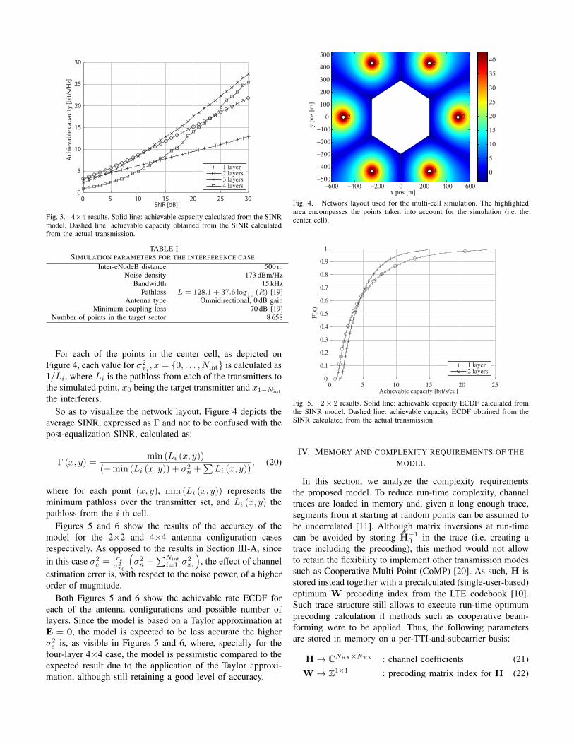
For each of the points in the center cell, as depicted onFigure 4, each value for σ2
xi, x = {0, . . . , Nint} is calculated as
1/Li, where Li is the pathloss from each of the transmitters tothe simulated point, x0 being the target transmitter and x1−Nint
the interferers.So as to visualize the network layout, Figure 4 depicts the
average SINR, expressed as Γ and not to be confused with thepost-equalization SINR, calculated as:
Γ (x, y) =min (Li (x, y))
(−min (Li (x, y)) + σ2n +
∑Li (x, y))
, (20)
where for each point (x, y), min (Li (x, y)) represents theminimum pathloss over the transmitter set, and Li (x, y) thepathloss from the i-th cell.
Figures 5 and 6 show the results of the accuracy of themodel for the 2×2 and 4×4 antenna configuration casesrespectively. As opposed to the results in Section III-A, sincein this case σ2
e = ceσ2x0
(σ2n +
∑Nint
i=1 σ2xi
), the effect of channel
estimation error is, with respect to the noise power, of a higherorder of magnitude.
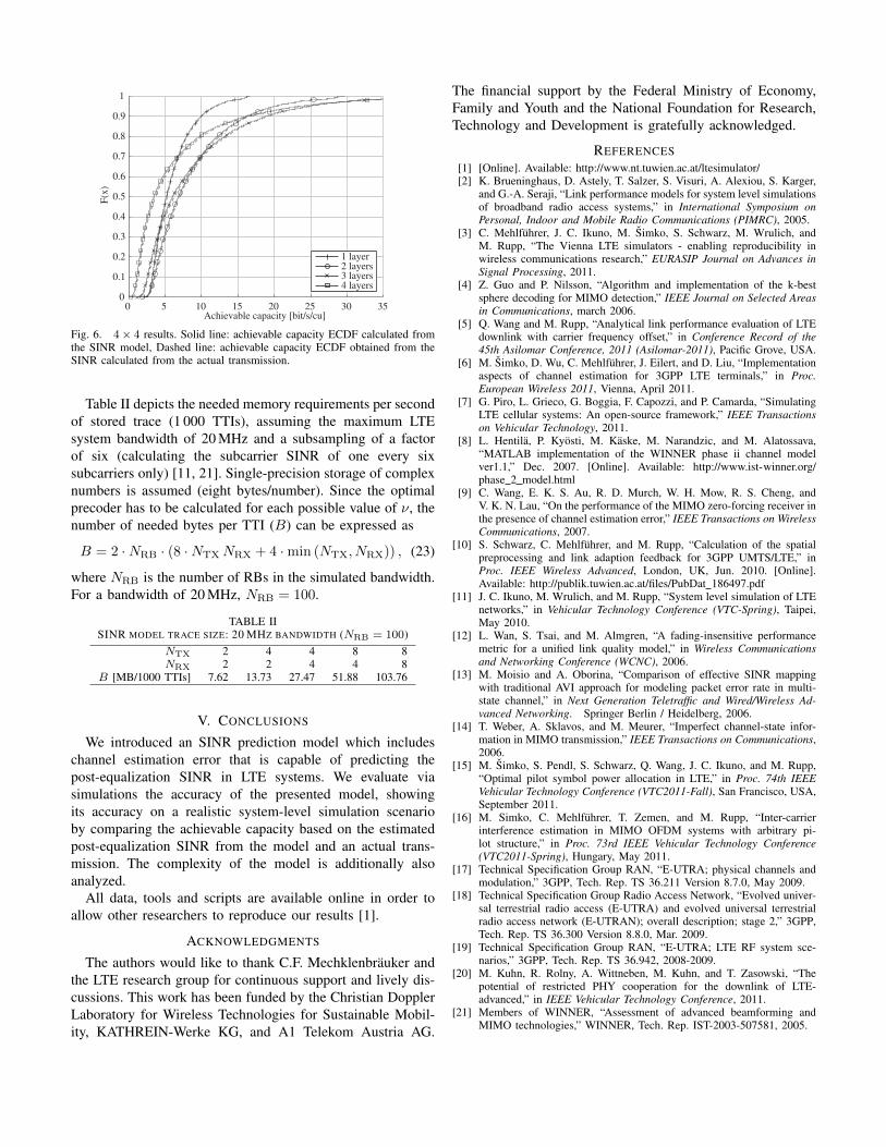
Both Figures 5 and 6 show the achievable rate ECDF foreach of the antenna configurations and possible number oflayers. Since the model is based on a Taylor approximation atE = 0, the model is expected to be less accurate the higherσ2e is, as visible in Figures 5 and 6, where, specially for the
four-layer 4×4 case, the model is pessimistic compared to theexpected result due to the application of the Taylor approxi-mation, although still retaining a good level of accuracy.
x pos [m]
y po
s [m
]
1
2
3
4
5
6
7
−600 −400 −200 0 200 400 600−500
−400
−300
−200
−100
0
100
200
300
400
500
0
5
10
15
20
25
30
35
40
Fig. 4. Network layout used for the multi-cell simulation. The highlightedarea encompasses the points taken into account for the simulation (i.e. thecenter cell).
0 5 10 15 20 250
0.1
0.2
0.3
0.4
0.5
0.6
0.7
0.8
0.9
1
Achievable capacity [bit/s/cu]
F(x)
1 layer2 layers
Fig. 5. 2× 2 results. Solid line: achievable capacity ECDF calculated fromthe SINR model, Dashed line: achievable capacity ECDF obtained from theSINR calculated from the actual transmission.
IV. MEMORY AND COMPLEXITY REQUIREMENTS OF THEMODEL
In this section, we analyze the complexity requirementsthe proposed model. To reduce run-time complexity, channeltraces are loaded in memory and, given a long enough trace,segments from it starting at random points can be assumed tobe uncorrelated [11]. Although matrix inversions at run-timecan be avoided by storing H−1
0 in the trace (i.e. creating atrace including the precoding), this method would not allowto retain the flexibility to implement other transmission modessuch as Cooperative Multi-Point (CoMP) [20]. As such, H isstored instead together with a precalculated (single-user-based)optimum W precoding index from the LTE codebook [10].Such trace structure still allows to execute run-time optimumprecoding calculation if methods such as cooperative beam-forming were to be applied. Thus, the following parametersare stored in memory on a per-TTI-and-subcarrier basis:
H→ CNRX×NTX : channel coefficients (21)
W→ Z1×1 : precoding matrix index for H (22)
0 5 10 15 20 25 30 350
0.1
0.2
0.3
0.4
0.5
0.6
0.7
0.8
0.9
1
Achievable capacity [bit/s/cu]
F(x)
1 layer2 layers3 layers4 layers
Fig. 6. 4× 4 results. Solid line: achievable capacity ECDF calculated fromthe SINR model, Dashed line: achievable capacity ECDF obtained from theSINR calculated from the actual transmission.
Table II depicts the needed memory requirements per secondof stored trace (1 000 TTIs), assuming the maximum LTEsystem bandwidth of 20 MHz and a subsampling of a factorof six (calculating the subcarrier SINR of one every sixsubcarriers only) [11, 21]. Single-precision storage of complexnumbers is assumed (eight bytes/number). Since the optimalprecoder has to be calculated for each possible value of ν, thenumber of needed bytes per TTI (B) can be expressed as
B = 2 ·NRB · (8 ·NTXNRX + 4 ·min (NTX, NRX)) , (23)
where NRB is the number of RBs in the simulated bandwidth.For a bandwidth of 20 MHz, NRB = 100.
TABLE IISINR MODEL TRACE SIZE: 20 MHZ BANDWIDTH (NRB = 100)
NTX 2 4 4 8 8NRX 2 2 4 4 8
B [MB/1000 TTIs] 7.62 13.73 27.47 51.88 103.76
V. CONCLUSIONS
We introduced an SINR prediction model which includeschannel estimation error that is capable of predicting thepost-equalization SINR in LTE systems. We evaluate viasimulations the accuracy of the presented model, showingits accuracy on a realistic system-level simulation scenarioby comparing the achievable capacity based on the estimatedpost-equalization SINR from the model and an actual trans-mission. The complexity of the model is additionally alsoanalyzed.
All data, tools and scripts are available online in order toallow other researchers to reproduce our results [1].
ACKNOWLEDGMENTS
The authors would like to thank C.F. Mechklenbrauker andthe LTE research group for continuous support and lively dis-cussions. This work has been funded by the Christian DopplerLaboratory for Wireless Technologies for Sustainable Mobil-ity, KATHREIN-Werke KG, and A1 Telekom Austria AG.
The financial support by the Federal Ministry of Economy,Family and Youth and the National Foundation for Research,Technology and Development is gratefully acknowledged.
REFERENCES[1] [Online]. Available: http://www.nt.tuwien.ac.at/ltesimulator/[2] K. Brueninghaus, D. Astely, T. Salzer, S. Visuri, A. Alexiou, S. Karger,
and G.-A. Seraji, “Link performance models for system level simulationsof broadband radio access systems,” in International Symposium onPersonal, Indoor and Mobile Radio Communications (PIMRC), 2005.
[3] C. Mehlfuhrer, J. C. Ikuno, M. Simko, S. Schwarz, M. Wrulich, andM. Rupp, “The Vienna LTE simulators - enabling reproducibility inwireless communications research,” EURASIP Journal on Advances inSignal Processing, 2011.
[4] Z. Guo and P. Nilsson, “Algorithm and implementation of the k-bestsphere decoding for MIMO detection,” IEEE Journal on Selected Areasin Communications, march 2006.
[5] Q. Wang and M. Rupp, “Analytical link performance evaluation of LTEdownlink with carrier frequency offset,” in Conference Record of the45th Asilomar Conference, 2011 (Asilomar-2011), Pacific Grove, USA.
[6] M. Simko, D. Wu, C. Mehlfuhrer, J. Eilert, and D. Liu, “Implementationaspects of channel estimation for 3GPP LTE terminals,” in Proc.European Wireless 2011, Vienna, April 2011.
[7] G. Piro, L. Grieco, G. Boggia, F. Capozzi, and P. Camarda, “SimulatingLTE cellular systems: An open-source framework,” IEEE Transactionson Vehicular Technology, 2011.
[8] L. Hentila, P. Kyosti, M. Kaske, M. Narandzic, and M. Alatossava,“MATLAB implementation of the WINNER phase ii channel modelver1.1,” Dec. 2007. [Online]. Available: http://www.ist-winner.org/phase 2 model.html
[9] C. Wang, E. K. S. Au, R. D. Murch, W. H. Mow, R. S. Cheng, andV. K. N. Lau, “On the performance of the MIMO zero-forcing receiver inthe presence of channel estimation error,” IEEE Transactions on WirelessCommunications, 2007.
[10] S. Schwarz, C. Mehlfuhrer, and M. Rupp, “Calculation of the spatialpreprocessing and link adaption feedback for 3GPP UMTS/LTE,” inProc. IEEE Wireless Advanced, London, UK, Jun. 2010. [Online].Available: http://publik.tuwien.ac.at/files/PubDat 186497.pdf
[11] J. C. Ikuno, M. Wrulich, and M. Rupp, “System level simulation of LTEnetworks,” in Vehicular Technology Conference (VTC-Spring), Taipei,May 2010.
[12] L. Wan, S. Tsai, and M. Almgren, “A fading-insensitive performancemetric for a unified link quality model,” in Wireless Communicationsand Networking Conference (WCNC), 2006.
[13] M. Moisio and A. Oborina, “Comparison of effective SINR mappingwith traditional AVI approach for modeling packet error rate in multi-state channel,” in Next Generation Teletraffic and Wired/Wireless Ad-vanced Networking. Springer Berlin / Heidelberg, 2006.
[14] T. Weber, A. Sklavos, and M. Meurer, “Imperfect channel-state infor-mation in MIMO transmission,” IEEE Transactions on Communications,2006.
[15] M. Simko, S. Pendl, S. Schwarz, Q. Wang, J. C. Ikuno, and M. Rupp,“Optimal pilot symbol power allocation in LTE,” in Proc. 74th IEEEVehicular Technology Conference (VTC2011-Fall), San Francisco, USA,September 2011.
[16] M. Simko, C. Mehlfuhrer, T. Zemen, and M. Rupp, “Inter-carrierinterference estimation in MIMO OFDM systems with arbitrary pi-lot structure,” in Proc. 73rd IEEE Vehicular Technology Conference(VTC2011-Spring), Hungary, May 2011.
[17] Technical Specification Group RAN, “E-UTRA; physical channels andmodulation,” 3GPP, Tech. Rep. TS 36.211 Version 8.7.0, May 2009.
[18] Technical Specification Group Radio Access Network, “Evolved univer-sal terrestrial radio access (E-UTRA) and evolved universal terrestrialradio access network (E-UTRAN); overall description; stage 2,” 3GPP,Tech. Rep. TS 36.300 Version 8.8.0, Mar. 2009.
[19] Technical Specification Group RAN, “E-UTRA; LTE RF system sce-narios,” 3GPP, Tech. Rep. TS 36.942, 2008-2009.
[20] M. Kuhn, R. Rolny, A. Wittneben, M. Kuhn, and T. Zasowski, “Thepotential of restricted PHY cooperation for the downlink of LTE-advanced,” in IEEE Vehicular Technology Conference, 2011.
[21] Members of WINNER, “Assessment of advanced beamforming andMIMO technologies,” WINNER, Tech. Rep. IST-2003-507581, 2005.