Embed Size (px)
Citation preview

Accurate Profile Measurement of the Low Intensity Secondary Beams in the CERN Experimental Areas
LPHE Seminar – 30/04/2018 – EPFL
Inaki Ortega

Outline
1. Introduction
2. First Prototype
3. Beam Tests of the First Prototype
4. Instrumentation for the Neutrino Platform
5. Beam Tests of the XBPF
6. Cosmic setup
7. Conclusions
2

Outline
1. Introduction
2. First Prototype
3. Beam Tests of the First Prototype
4. Instrumentation for the Neutrino Platform
5. Beam Tests of the XBPF
6. Cosmic setup
7. Conclusions
3
Objective of the thesis work:
Develop a new monitor, as well as the associated electronics, in order to accurately determine the beam position and profile for the lowest intensity beams that are delivered to the CERN Experimental Areas.
4

What are the experimental areas?
5

Secondary beam lines
Fixed Target
Injector
Slow extraction
PS or SPS machine
Experimental Areas
Beam monitor
6

- Wide variety of beams: different particle types, intensities, and energies.7
- Large number of experiments and researchers: R&D in physics, particle detectors and accelerators technology, among others. Well known by LPHE researchers.
- The EA utilise ~41% of the protons produced at CERN.

The North Area Extension: The CERN Neutrino Platform
ProtoDUNE: Neutrino detectors consisting in ~700 tons of liquid Argon
8
- Very low energy beams- Very low rate- Large beam spot size

Monitors in the experimental areas:
- Multi-wire analogue chambers- Delay wire chambers (DWC)- Finger scintillator scanner (FISC)
A FISC profile
Multi-wire analogue chamber
These detectors have greatly performed for decades.
However:- They are ageing.- They cannot fulfil the requirements of the Neutrino
Platform, particularly individual particle detection and active area size.
9

- High detection efficiency: > 90%.
10
- Spatial resolution: 0.5 or 1 mm.
- Maximum beam intensity: ~107 particles/second/mm2.
- Wide dynamic range: 0.5 GeV to 450 GeV.
- Minimise material budget: < 0.5% radiation thickness (x/X0).
- Two detector sizes: 10cm x 10cm and 20cm x 20cm.
- Moderate radiation hard: ~kGy.
- Robust and easy to maintain.
- Reasonable cost.
- Operation in vacuum.
Requirements of the new instrumentation:
- Individual particle detection.
Review of most common tracking technologies: GEM, Micromegas, Semiconductors, and Scintillating Fibres
11

12
GEM Micromegas
Disadvantages:- Sparks (especially at high rates).
Main physical processes:- Gas ionisation.- Avalanche.

13
Semiconductor Detectors Scintillating Fibres
Advantage: high performance.Disadvantages: - Expensive- Cooling needed.
Advantage: non expensive material.Disadvantage: production can be cumbersome.
“Solid state ionisation chamber”:Semiconductor ionisation + drift.Low gain → sensitive electronics.
Working principle:Excitation of atoms → scintillation (light).Light trapping + photodetector.
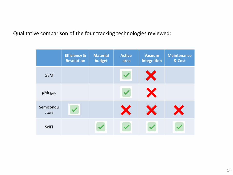
Efficiency & Resolution
Material budget
Activearea
Vacuum integration
Maintenance& Cost
GEM
μMegas
Semiconductors
SciFi
Qualitative comparison of the four tracking technologies reviewed:
14

Outline
1. Introduction
2. First Prototype
3. Beam Tests of the First Prototype
4. Instrumentation for the Neutrino Platform
5. Beam Tests of the XBPF
6. Cosmic setup
7. Conclusions
15

- One plane of 64 packed square fibres of 1mm profile reconstruction over 64mm.
- Mirror on one end to increase light collection.
- The number of particles/channel is counted profile and intensity measurement.
- Fibres in vacuum, photodetector in air Monitor integrated in vacuum.
- Pixelated readout every ‘fibre – photodetector’ pair is a channel.
16

Choice of Scintillating Fibre
Small setups to characterise the signal from different fibres → Measurements done in LPHE.
17
• Square cross-section → good beam coverage with a single or double layer design.
• Two main manufacturers reviewed: Saint-Gobain and Kuraray.
• Two thicknesses investigated: 0.5mm and 1mm.
18
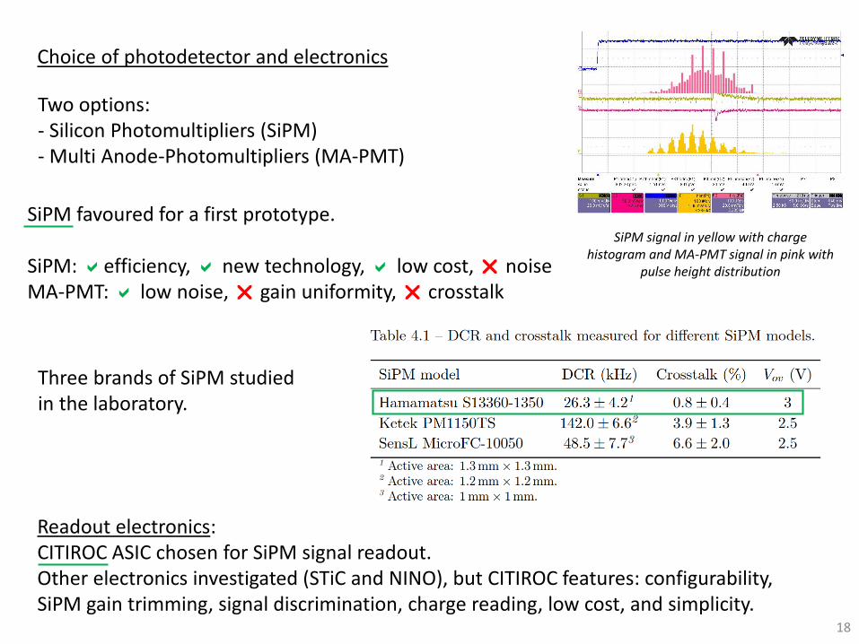
Choice of photodetector and electronics
Two options:- Silicon Photomultipliers (SiPM)- Multi Anode-Photomultipliers (MA-PMT)
Three brands of SiPM studied in the laboratory.
Readout electronics:CITIROC ASIC chosen for SiPM signal readout.Other electronics investigated (STiC and NINO), but CITIROC features: configurability, SiPM gain trimming, signal discrimination, charge reading, low cost, and simplicity.
SiPM signal in yellow with charge histogram and MA-PMT signal in pink with
pulse height distribution
SiPM favoured for a first prototype.
SiPM: efficiency, new technology, low cost, noiseMA-PMT: low noise, gain uniformity, crosstalk

The array of fibres hanging upside down for glue drying Polishing of the fibres on the mirror end
19
First prototype built in the workshops of LPHE

Fibre connector after polishing PCB board housing the 32 SiPM.The alignment to the fibre connector is guaranteed by
precision dowel pins
20

The SiPM board connected to the CITIROC board The prototype mounted and being tested in the lab.The VME counters are in the lower part of the table
21

Outline
1. Introduction
2. First Prototype
3. Beam Tests of the First Prototype
4. Instrumentation for the Neutrino Platform
5. Beam Tests of the XBPF
6. Cosmic setup
7. Conclusions
22

23
Beam tests in the North Area

SciFi
DWC
FISC
SciFi intensity
Scintillator Paddle intensity
24

Profile analysis of 180 GeV/c proton/pion beams of three different intensities
Intensity = 3.4×10⁴ particles/second
Intensity = 8.2×10⁴ particles/second
Intensity = 6.5×10⁵ particles/second
SciFi DWC FISC
25
The SciFi performed well in all intensities; the DWC had troubles with high intensities;the FISC could not resolve low intensity beams.

26
Measurements with lead ion beams
SciFi profiles were wider than the DWC.
Believed to be optical crosstalk between the fibres, caused by the large energy deposition of lead ions.
Possible solution: aluminium coating of the fibres.

Outline
1. Introduction
2. First Prototype
3. Beam Tests of the First Prototype
4. Instrumentation for the Neutrino Platform
5. Beam Tests of the XBPF
6. Cosmic setup
7. Conclusions
27

28
Specific requirements:• 200mm X 200mm active area• Individual particle detection• 1mm spatial resolution• High efficiency > 90%• Fibre multiplicity information• Use White Rabbit for common
time reference• Vacuum integrated• Detector size constraint
Two versions of the detector with different functions.
XBPF:• Beam profile• Momentum spectrometer
XSCINT• Trigger generation• Time-of-flight
Beam instrumentation for the Neutrino Platform: XBPF

XBPF
29
Fibres chosen: Kuraray, 1mm thickness.

30

31
XSCINT

32
Different functions in the beam line
Trigger + ToF: 1 XSCINT
Profile + Trigger + ToF:2 XBPF - 1 XSCINT
Spectrometer + Profile: 4 XBPF

33
Electronics Architecture
- Trigger generation for the beam instrumentation and the neutrino experiments.
- Single event time-stamping with White Rabbit (special low latency network for high-performance time transfer).
- Dataflow from front end to back end via optical link.

34
Front End Board
• 192 SiPM aligned to the XBPF fibres.
• Hamamatsu C11204 power supply for SiPM.
• 6 CITIROC ASIC.
• Xilinx FPGA Artix 7.
• SFP module with Gbit transceiver.
New development that features:
35
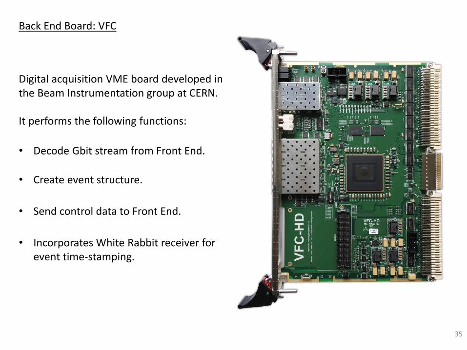
Back End Board: VFC
• Decode Gbit stream from Front End.
• Create event structure.
• Send control data to Front End.
• Incorporates White Rabbit receiver for event time-stamping.
Digital acquisition VME board developed in the Beam Instrumentation group at CERN.
It performs the following functions:

Outline
1. Introduction
2. First Prototype
3. Beam Tests of the First Prototype
4. Instrumentation for the Neutrino Platform
5. Beam Tests of the XBPF
6. Cosmic setup
7. Conclusions
36

37
Two weeks of accelerator time booked for us: from 20 November to 4 December 2017.
Fighting against the clock
The fibre assemblies were ready at the beginning of October.
The vacuum tanks arrived in the middle of October.
The front end boards were ready for testing at the beginning of November.
Next beam time available would be May 2018 (with much luck…).
October November December
Beam timeFibres ready
Vacuum tanks @CERN
ElectronicsAccelerator stops

But we did it!!
38
Large efforts were done in the last quarter of 2017 in order to be ready for the beam tests.
Even the Time-of-Flight system was working!

39
Vacuum tests
10-3 mbar achieved(North Area requirement)

Debugging in the laboratory
40

First profile of a Sr90 source obtained locally (via USB) in the laboratory
41

42
First profile of a Sr90 source obtained remotely via the VFC (optical link) in the laboratory
LocalRemote

Installation of the monitors in the T10 beam line of the East Area
(24 November)
43

One XBPF and one XSCINT per tank
Layout of the T10 setup
*DWC = Delay Wire Chamber for beam profile reconstruction*SCINT = Scintillator paddles for beam intensity measurement
44

Upstream monitor, close to a DWC and a Scintillator Paddle
Downstream monitor 14m further away
45

XBPF front end board installed on top of the fibres
Control room: VME crate with the VFC board and the Time-of-Flight TDC
All the electronics have the same time reference provided via White Rabbit.
46
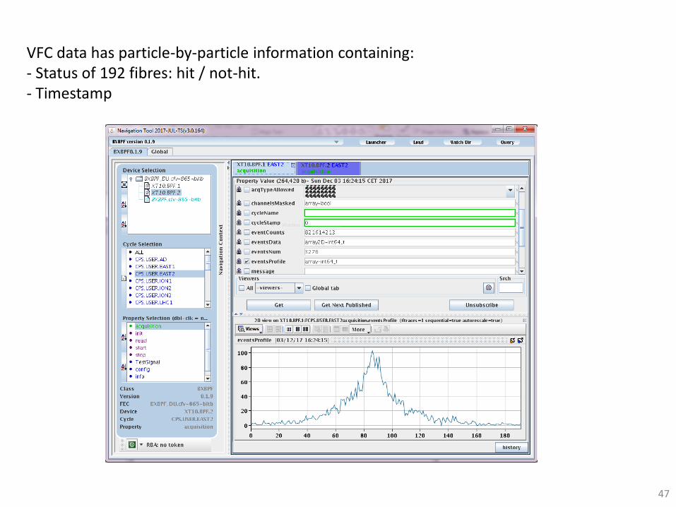
VFC data has particle-by-particle information containing:- Status of 192 fibres: hit / not-hit.- Timestamp
47

Preliminary results of the East Area tests
The first analysed data sets showed an overall good performance with:- Efficiency higher than 90% - Fibre crosstalk lower than 3%
However, the analysis is long and hard and is still ongoing. There are some phenomena that have to be understood.
48
Example of analysis plots:
→ Preliminary
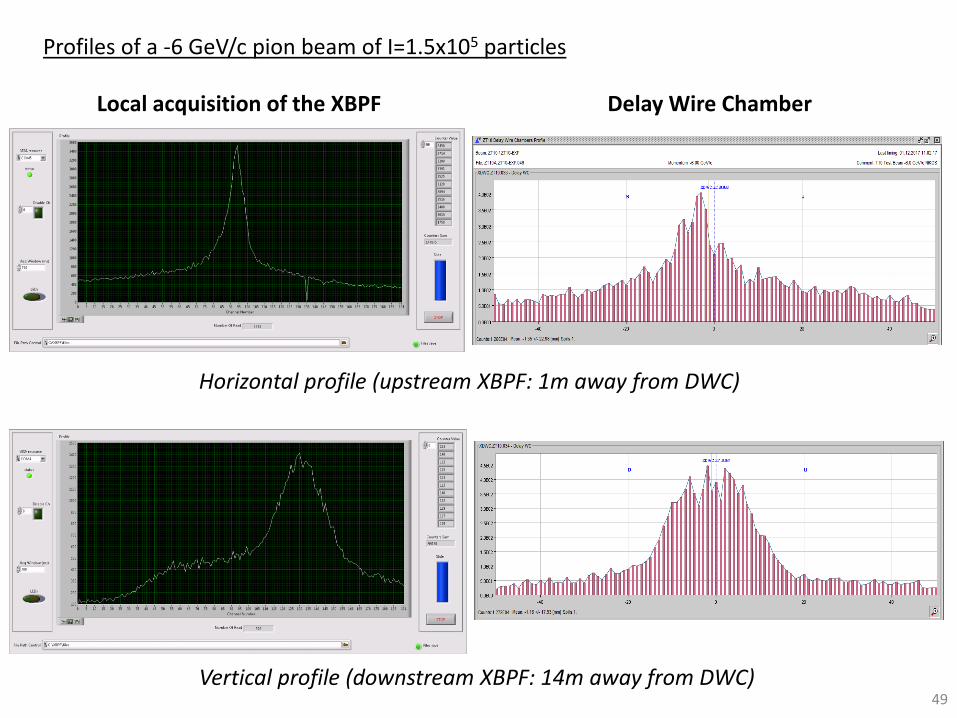
Local acquisition of the XBPF Delay Wire Chamber
Profiles of a -6 GeV/c pion beam of I=1.5x10⁵ particles
Horizontal profile (upstream XBPF: 1m away from DWC)
Vertical profile (downstream XBPF: 14m away from DWC)49

XSCINT detection efficiency = 94.0 ± 0.1%
Trigger efficiency measurement
50

What about the time of flight?
51

52
Time-of-flight principle
XSCINT 1 XSCINT 2
Incoming particle:- known momentum (p)- unknown mass (m)
∆𝑡 = 𝑡2 − 𝑡1 =𝐿
𝑝𝑐2𝑚2𝑐4 + 𝑝2𝑐2
The time resolution of our system limits our ability to identify particles.
t1 t2
L
Secondary beams are composed of many particles not identified

53
TDC used: SVEC FMC-TDC
Mezzanine board mounted in the SVEC VME carrier.
Incorporates ACAM Time-to-digital converter.
Fully compatible with White-Rabbit.
81 ps time resolution (1 sigma).
Constant Fraction Discriminator used: CAEN N842
NIM module quickly available and easy to use.
400ps time walk.
NIM output → signals need TTL conversion for compatibility with TDC.

Time-of-Flight performance in the East Area tests
Preliminary
Time resolution of 900ps: allows distinguishing beam composition at low momenta.
54

Outline
1. Introduction
2. First Prototype
3. Beam Tests of the First Prototype
4. Instrumentation for the Neutrino Platform
5. Beam Tests of the XBPF
6. Cosmic setup
7. Conclusions
55

56
Sandwich of 2 XSCINT and 1 XBPF.
Excellent way of measuring the performance of the detector.
Generates data uninterruptedly → people for protoDUNE DAQ working on integration can access real data from cosmics.
Cosmic setup
No time pressure as in the accelerators → scan on various parameters to investigate the performance of the detector.

Example measurement with the SiPM overvoltage = 3V, preamp value 16 (x 12.8), discriminator’s threshold to 3.5 photons:


Monte Carlo simulation of the cosmic setup
• Recreates geometry of the setup.
Straight tracks are originated at a fixed altitude, with an arbitrary x0 and an arbitrary angle distribution according to cos2θ.
• Generates data file identical to XBPF monitor, so it can be analysed identically.
• Uses random generator to create cosmic’s tracks.

Simulation data analysed:
The high multiplicity is due to real particles crossing 2 fibres due to their angle!
The optical crosstalk for the uncoated fibres is <3%.For the aluminised fibres <1%.

65
Time-of-flight improvements are also being investigated:
• Use of better cables.
• Constant Fraction Discriminators with less walk time.
• Constant Fraction Discriminators with direct TTL output to avoid logic conversion.
<700ps achieved in the cosmic test bench with good quality cables (50m)

Outline
1. Introduction
2. First Prototype
3. Beam Tests of the First Prototype
4. Instrumentation for the Neutrino Platform
5. Beam Tests of the XBPF
6. Cosmic setup
7. Conclusions
66

Conclusions
• A SciFi monitor based on a pixelated readout, and integrated in vacuum, performs better than the present monitors under secondary beams.
• It shows limitations with Pb-ions that are believed to come from crosstalk → still under investigation.
• The expected lifespan of the monitor is long, several years. In case of failure, the modular design would allow for an easy replacement of the faulty component.
• It is also capable of extending the functionalities with the Time-of-Flight at low momenta.
• The cost of the SciFi monitor is lower than the present detectors and its maintenance is simpler (no gas, no HV).
67
Final remark
This simple and cost-effective development could extend its application to other fields outside particle physics, such as: radioprotection, management of radioactive waste, medicine, or even industrial applications in which it is necessary to track charged particles.
68

Thank you very much for your attention!
69

Backup slides
70

Additionally, the measurements done with the fibres were used to tune a Geant4 simulation.
71
Saint-Gobain can produce square multi-clad fibres → improved light trapping.
Kuraray show better overall quality in controls done at CERN [C Joram et al. Characterization studies on scintillating fibres. Technical report, CERN, 2006]
The choice for the first prototype: Saint-Gobain fibres, 1mm thickness → guarantee a clear signal to reconstruct the beam profile.