Embed Size (px)
Citation preview
Accurate Localization of RFID Tags Using PhaseDifference
Cory Hekimian-Williams, Brandon Grant, Xiuwen Liu, Zhenghao Zhang, and Piyush KumarDepartment of Computer Science, Florida State University, Tallahassee, FL 32306
{hekimian,bgrant,liux,zzhang,piyush}@cs.fsu.edu
Abstract—Due to their light weight, low power, and practicallyunlimited identification capacity, radio frequency identification(RFID) tags and associated devices offer distinctive advantagesand are widely recognized for their promising potential incontext-aware computing; by tagging objects with RFID tags,the environment can be sensed in a cost- and energy-efficientmeans. However, a prerequisite to fully realizing the potential isaccurate localization of RFID tags, which will enable and enhancea wide range of applications. In this paper we show how to exploitthe phase difference between two or more receiving antennas tocompute accurate localization. Phase difference based localizationhas better accuracy, robustness and sensitivity when integratedwith other measurements compared to the currently populartechnique of localization using received signal strength. Usinga software-defined radio setup, we show experimental resultsthat support accurate localization of RFID tags and activityrecognition based on phase difference.
Index Terms—RFID localization, phase difference, maximumlikelihood estimation, software-defined radio.
I. INTRODUCTION
With the integration of computing into everyday objectsand activities, ubiquitous computing has become part of ourday to day lives. Due to the mobility and dynamic natureof the communication structure as well as the physical en-vironment, ubiquitous computing has unique challenges andpresents unprecedented opportunities [1], making context-aware computing a new paradigm. In this emerging context-aware computing, the applications adapt not only to thecomputing and communication constraints and resources, butalso to the contextual information, such as the objects inthe surroundings and people and activities in the vicinity,and even emotional and other states of the user [1]. Torealize these potential improvements and make the context-aware applications cost-effective, the systems must be able to“sense” the environment effectively, with low energy and lowcost [22], [21]. While traditional approaches such as vision-sensor and active sensor based methods are obvious choicesfor object recognition and localization [17], realization of arobust and cost-effective system based on these sensors hasyet to be implemented after several decades of research.1
Recent deployment of radio frequency identification (RFID)technology for efficient asset tracking and management hasmade RFID tags and associated devices widely available withlow cost and low energy usage. For example, there are active
1This does not imply that computer vision does not make any progress; onthe contrary, computer vision has made numerous important breakthroughs.
RFID tags that typically last for five to seven years witha compact battery as a reliable wireless signal transmitter;obviously passive RFID tags have practically no lifetime limit.Clearly RFID tags, at a coarser level, provide a cost-effectiveand energy-efficient way of solving the environment sensingproblem. One straightforward solution is to attach one or moreRFID tags to each object of interest in the environment. AsRFID tags have a limited range of readability, by reading allthe tags in the proximity, using a reader or similar device, acomputer can approximate its environment based on the sensedobjects. Additionally, a unique advantage of RFID technologyover vision and other sensor based methods is that RFID tagsdo not require line of sight in order to be “seen” and thus avoidproblems associated with occlusion. Because of the uniqueand strategic advantages of RFID tags, they have been heavilyinvestigated for numerous applications (e.g. [8], [17], [3], [16],[9], [15]).
While coarse-grained localization, that is, whether an objectis present or absent in the proximity, is sufficient for manyapplications, a large number of applications will benefit fromaccurate location information of objects. For example, in asmart house setting, a low-cost solution of knowing preciselywhere people are and what objects are close to them willenable optimization of user interfaces and energy utilizationand enhanced convenience. In addition, it is often important totrack the motion of people/objects so that dynamic activitiescan be recognized and modeled. These applications havemotivated numerous localization schemes and systems forRFID devices (see [5], [27] for recent reviews). Even thoughthere are other schemes for localization such as using WiFidevices, WiFi devices are much larger in size and have muchmore strict power requirements, which makes RFID tags themost attractive choice for numerous applications.
In this paper, to achieve a fine-grained localization, weexploit the phase difference of the received signals at differentantennas. While the received signal strength can attenuatequickly and therefore may lead to significant estimation errorsof the location, the phase difference, on the other hand,can be estimated much more reliably as long as the signal-to-noise ratio is not too small. A unique advantage of theproposed phase difference method is that by measuring thephase difference between pulses within the same burst, onecan estimate the motion of the object, thus making it feasibleto monitor human activities at natural speeds. For example,our experiments suggest that we can reliably measure phase
difference within 0.57◦ (see Figs. 6 and 7). Another advantageof phase difference is that it can be combined with received-signal-strength-based scene analysis methods to improve thelocalization accuracy by using phase difference to estimate thelocal distance to reference tags.
To evaluate the effectiveness of phase difference for local-ization, we set up a plot study system that consists of activeRFID tags, Universal Software Radio Peripheral (USRP) asreceivers, and a pan-tilt unit to accurately place tags for variouscontrolled experiments. Note that the model and the phasedifference estimation methods apply to passive RFID tags ina similar manner2; here we limit our scope to active RFIDtags, mainly so that our experiments are easy to replicate.The initial results we have are encouraging even though morelocalization experiments under real-world settings need to befurther investigated.
The rest of the paper is organized as follows. Section IIoutlines the general localization problem and then reviews therelated work on localization using RFID technology in thegiven framework by categorizing them based on several crite-ria. In Section III we describe the phase difference model andSection IV presents algorithms for phase difference estimation.Section V presents experimental results on localization andmotion estimation and modeling. Section VI concludes thepaper with a summary and discussion.
II. RELATED WORK
The most general setup for RFID localization can be postedin a statistical inference framework [6], [14]. We representthe region of interest as a scene that consists of K RFIDtags (wireless signal transmitters), whose configuration attime t is given by the location in the three dimensionalspace, the orientation of the transmitter’s antenna, and thepower level3; and N receivers, whose configuration is givensimilarly. Given a number of measurements between the tagsand the receivers, the localization problem is to estimatethe probability distribution of the location of the tags andreceivers. Note that even though the localization algorithmsdeveloped for wireless ad-hoc networks and in particular,wireless sensor networks [14], can, in theory, be appliedto localization using RFID technology, due to the uniquecharacteristics of RFID technology, for example, no or verylimited computation capabilities available on the tags, thepotential large number of tags, and typical indoor operatingenvironments; localization algorithms specific to RFIDs shouldbe developed and studied [4].
The existing localization methods can be categorized basedon 1) the constraints (i.e., range-free (based on connectivityinformation) or continuous measurements (such as receivedsignal strength)), 2) the temporal nature of locations of tagsand receivers (e.g., anchor-free or with reference tags orreceivers at fixed locations), 3) and the statistical inference
2For example, we can use one RFID reader to power and initiate wirelesscommunications from passive tags.
3The power level of an active RFID tag is constant; for a passive tag, itcan be changed by changing the power level of the reader.
algorithm given the constraints. In the given setting, it isclear that range-free localization methods can be seen as aspecial case of using received signal strength, where onlybinary values of received signal strengths are available throughreachability.
Before we summarize existing methods and systems forlocalization using RFID technology, we stress the significantdifferences between the results based only on computer simu-lations and the results based on physical system measurements.While RFID tags and readers are widely available, settingup an experimental system is not a straightforward task, ascapturing wireless signals is full of challenges [23]. To avoiddifficulties associated with prototyping, simulation is oftenused in various localization studies. For example, Wang etal. [20] propose an active scheme and passive scheme forRFID localization and provide supporting evidence throughsimulation in Matlab; Zhang et al. [25] propose the use ofdirection estimation for two dimensional localization; whilethey propose to use the phase difference to estimate thedirection of arrival but they provide only simulation results.Bouet and Pujolle [4] use connectivity constraints throughdetectability of tags of mobile readers. While simulationresults can be used to verify principles and theoretical aspectsof localization and other methods, they are not sufficient toevaluate RFID localization performance as the wireless signalsare affected by many other factors. Therefore, localizationaccuracy comparison between methods based on physicalsystem measurements and methods based on simulation results(e.g. [4]) should be interpreted carefully.
Due to the difficulties of capturing and processing RFIDcommunications, localization systems commonly rely on avail-able wireless measurements at the receivers (e.g., RFIDreaders) such as received signal strength (RSS) (e.g., [11],[13]).4 These RSS measurements can be binarized using somehardware or software threshold, resulting in binary readabil-ity/reachability values, which can be used as connectivityconstraints in range-free localization systems. When the trans-mitting power of the transmitters can be dynamically changed,one can obtain a multi-level approximation of the range usingmultiple readability values [13]. This can be interpreted as anintermediate range representation between continuous valuesand range-free binary values. These measurements lead toconstraints on the location and the orientation of tags as wellas on the readers, which are then used by a statistical inferencealgorithm for localization. The localization step is often calledthe scene analysis step [5].
As the measurements and therefore constraints are pairwisebetween transmitters and receivers, they can be used to localizeeither transmitters or receivers using known fixed receiversor transmitters (called anchors), or both as in anchor-freesystems. For example, SpotON [11] is based on RSS measure-ments estimated from adjustable sensors and the measurements
4There are other measurements that can be used to estimate the distance,such as time difference of arrival [18] and time of arrival; these measurementsare rarely used in RFID technology as these measurements are difficult andexpensive to implement.
are used to estimate inter-tag distances with improved accuracyby calibrating radio signals to reduce the effects of hardwarevariability; as custom-built sensors used in SpotON are bothtransmitters and receivers, the system is more similar toa wireless ad-hoc network than to an RFID-based system.Landmarc [13] localizes RFID tags through comparing profileswith a number of reference tags with known locations; inthis system nine readers with eight different power levels areused and a number of reference tags (i.e., tags with fixed andknown location) are used for localization. To localize a tag, itsestimated signal strengths from all the readers are comparedto the corresponding measurements of reference tags. Theestimated tag location is given by a weighted average of the k-nearest neighbors. The system is robust to some environmentalfactors as the reference and the unknown tags are subject tothe same conditions; however, it is sensitive to tag orientationas the reference tags and the unknown tag can be orienteddifferently, specially when the tag is used to track moving ob-jects. VIRE [26] uses the same localization method as in [13]and improves the efficiency of Landmarc by introducing aproximity map so that only tags in the neighboring areas needto be compared, rather than all the tags as in [13]. Zhang etal. [24] improves the localization accuracy of [13] by modelingthe noise so that dissimilarity among tags is reduced for morereliable nearest neighbor matching and estimation. While the Knearest-neighbor estimation is commonly used as the inferencealgorithm, statistical inference algorithms are also used. Forexample, Bekkali et al. [2] propose to use Kalman filtering toestimate locations of unknown tags based on multilaterationto the reference tags using two mobile RFID readers. A moregeneral statistical inference framework is to use the Bayesiannetwork [12] to estimate the locations and even orientation oftags and readers.
In this paper, we study the phase difference for accuratelocalization and motion tracking and activity recognition.In contrast to Zhang et al. [25], where phase difference isused only in simulations, our phase difference estimation isimplemented and demonstrated using a prototype system andtherefore our study is directly relevant to RFID applicationsthat rely on localization. Our experiments show the phasedifference can be estimated with high accuracy and can beused for three dimensional positioning. To the best of ourknowledge, this is the first time that phase differences fromRFID tags are measured reliably and are used for threedimensional positioning, motion estimation and tracking.
III. SYSTEM SETUP AND COMMUNICATION MODEL
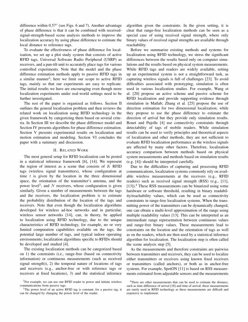
In this paper, we focus on quantitative models of phasedifference for RFID tags. The phase difference measurementsare based on software-defined radios due to their flexibilityin implementing various algorithms. To be more precise inpresenting our model and algorithms, our formulation is basedon the following setup we have. Clearly, for a different setup,the phase difference estimation algorithm and results shouldbe similar even though changes may need to be made. Asshown in Fig. 1, the system we have consists of RFID tags,
Fig. 1. The system setup (consisting a software-defined radio (USRP), RFIDtags, and a pan-tilt unit) we have used for accurate manipulation and placementof tags for controlled experiments.
a software-defined radio system, and a pan-tilt unit. Thetags we use are the M100 asset tags from RF Code5. Thecarrier frequency of the tags is 433.92 MHz with typicaltransmission range over 90 meters (sufficient to cover entirelytypical houses and offices). The tag uses the on-off keying(OOK) for communication, as it is simple to implement andis energy efficient (to prolong battery life). To meet theenergy efficiency requirement, the signals are transmitted ina burst only at almost regular internals6. Using a compactbattery (Lithium CR2032, which is replaceable), a tag typicallylasts over seven years. During each burst, a fixed number ofpulses are transmitted at seemingly the same magnitude withpredetermined intervals, where we suspect that the lengths ofthe intervals are used to identify the tag. Each pulse is basicallya sine wave for a short period of time on the carrier frequency.
To be able to implement various phase difference estima-tion algorithms and measure various aspects of the wirelesscommunication, we have used software-defined radios for theexperiments due to their flexibility7. The software-definedradios are based on the USRP from Ettus Research LLC8,along with software modules and packages from the GNUsoftware-defined ratio project9. We have used two RFX400daughter boards, where both are configured as receivers. Inorder to estimate phase difference, the two receivers mustbe driven with the same sampling clock; otherwise, even atiny mismatch between the clock will result in a huge phasedifference. The USRP guarantees that the two channels aredriven by the same sampling clock. In our system, the daughterboards are tuned to 433.92 MHz.
A. Communication Model
The wireless communication between the tags and theUSRP unit is a typical wireless communication system and
5Specifications available from http://www.rfcode.com.6The intervals are randomly perturbed for collision avoidance.7Note the algorithms presented can be implemented in hardware efficiently
if a hardware implementation is desired.8http://www.ettus.com/.9Available http://gnuradio.org.
here we follow the model in [19]. Based on our observation,the wireless signal from an RFID tag in one pulse can bedescribed as A cos(2πfct), where A is the constant magnitudeand fc is the carrier frequency. At each daughter board,the received signal at its antenna is amplified and down-converted to the baseband. A baseband signal is representedby the inphase and quadrature components, denoted as I(t)and Q(t), respectively. If the carrier of the tag and the USRPare on exactly the same frequency, both I(t) and Q(t) shouldbe a constant, depending only on the phase of the carriers.However, there will always be a frequency difference betweenthe carrier of the tag and the carrier of the USRP due tothe manufacturing process of the oscillator. Let fr denote thefrequency tuned to at the receivers. The waveforms at receiver1 can be represented as
I1(t) = A1 cos(2π(fr − fc)t + φ1) + σ1n11,Q1(t) = A1 sin(2π(fr − fc)t + φ1) + σ1n12,
(1)
where A1 is the received signal magnitude, φ1 is the initialphase difference between the carrier at the tag and the carrierat the receiver, the initial carrier phase at the receiver, n11 andn12 are Gaussian noise terms of unit variance, and σ1 is thenoise level. Using similar notations, the waveforms at receiver2 can be represented as
I2(t) = A2 cos(2π(fr − fc)t + φ2) + σ2n21,Q2(t) = A2 sin(2π(fr − fc)t + φ2) + σ2n22.
(2)
Wireless signals travel at the speed of light, such that φ1
and φ2 depend on the lengths of the paths from the tag to thereceivers. However, the exact values of φ1 and φ2 also dependon the initialization process of the hardware, such that theycannot be used directly for distance and location estimation.Fortunately, the phase difference, i.e., φ1 − φ2, captures thedifference of the distances of the paths, which can be used forlocation estimation.
B. Measured Waveforms and Phase Difference
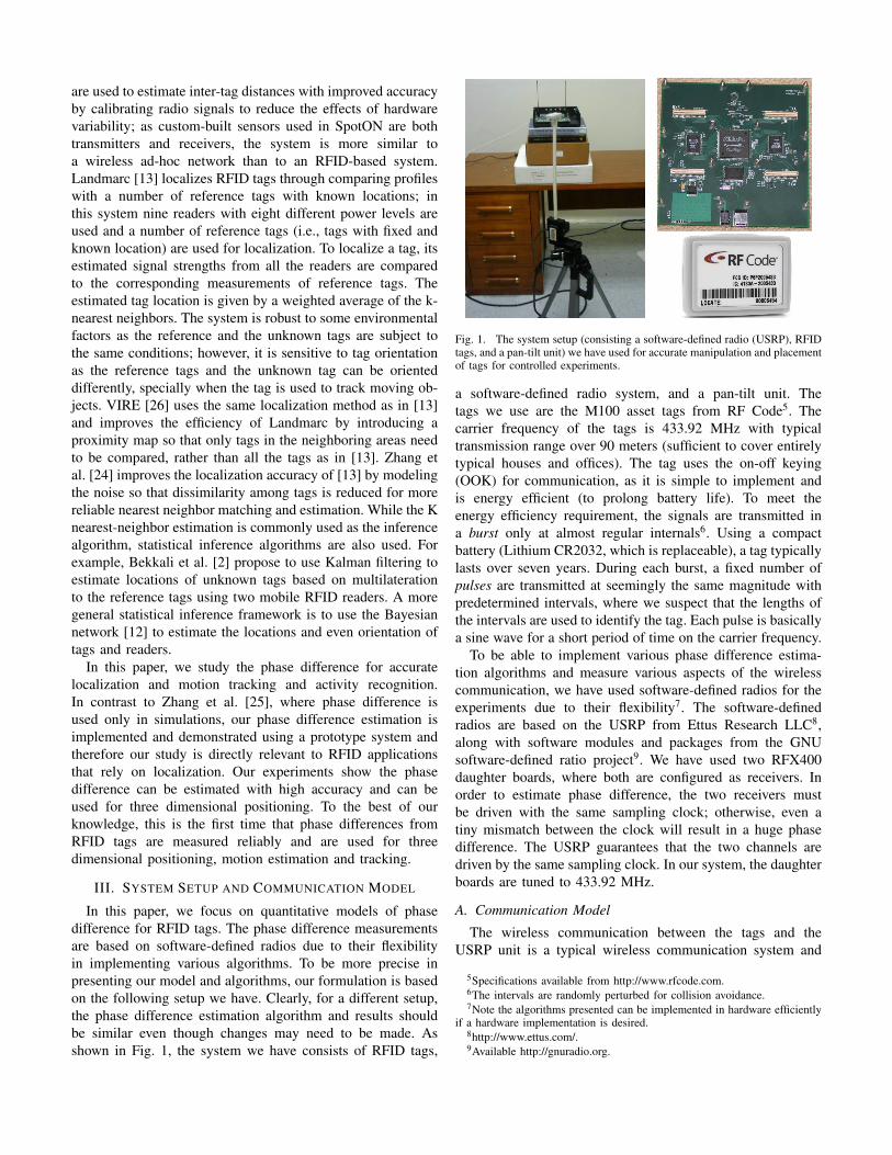
To demonstrate that the wireless signals are reliable forphase difference estimation, Fig. 2 shows one burst receivedat the two antennas along with a zoomed version showing thesignals during one pulse. These plots show clearly that thesignals are robust and allow for reliable phase estimation andthus the phase difference estimation.
The waveforms received at the antennas as given in Eqs.(1) and (2) allow a straightforward estimation the phasedifference. That is, at time t, the phase difference should betan−1(Q1(t)/I1(t)) − tan−1(Q2(t)/I2(t)). Figure 3 showsone example of estimated phases during a pulse and a typicaldistribution of estimated phase difference during a burst.Figure 3(a) plots I1(t) v.s. Q1(t) (green ’+’) and I2(t) v.s.Q2(t) (red ’+’); where the time is encoded by the intensityof the colors; it shows clearly the constant phase difference.Figure 3(b) shows the probability distribution of the phasedifferences of a stationary tag during one burst; here theprobability distribution is estimated using the Parzen windowmethod [10]. In this typical example, the standard deviation
(a)
(b)
Fig. 2. Waveforms received at antennas during a transmission of a burst.(a) Estimated magnitudes of the signals received at two antennas (top andbottom); (b) Each panel shows the received signals at an antenna, here theblue plot shows I(t), and the red one shows Q(t), and the black dashed oneshows the magnitude
pI(t)2 + Q(t)2.
(a) (b)
Fig. 3. Phase difference estimation example for one pulse. (a) The signals attwo antennas, showing clearly the constant phase shift; (b) The estimatedprobability distribution of the estimated phase differences during a burst;here it is estimated using a Parzen window and the standard deviation ofthe distribution is 0.954◦.
of the phase differences is 0.954◦. For the waveforms at433.92 MHz, this corresponds to a localization accuracy of 1.8millimeters.10 While the estimated accuracy is under an idealsituation, it shows clearly the feasibility of phase differenceestimation for accurate localization.
IV. MAXIMUM LIKELIHOOD ESTIMATION OF THE PHASEDIFFERENCE
While the straightforward estimation the phase difference isoften sufficient, for more reliable and accurate estimation in
10Given by 0.954360
× 299792458433920000
meter = 0.0018 meter, where 299792458is the speed of light (meters/second).
cases such as phase difference tracking for moving RFID tags,one can use the maximum likelihood estimation. One optionis to estimate the phase for each antenna separately and thencompute the phase difference. The other option is to directlyestimate the phase difference. In the first case, suppose wehave n samples from the first antenna, I1(t1), . . . , I1(tn), andQ1(t1), . . . , Q1(tn). As the sampling rate of the channels isconstant and known, we have ti = i×∆t, where ∆t is givenby the sampling rate.
Under the common assumption that the noise terms arestatistically independent and follow the Gaussian distribution,we have
φ̂1 = arg maxφ1
∏i=ni=1 (P (I1(ti)|φ1)× P (Q1(ti)|φ1)
= arg minφ1
∑i=ni=1 (I1(ti)−A1 cos(∆ω × i + φ1))2
+(Q1(ti)−A1 sin(∆ω × i + φ1))2,(3)
where ∆ω = 2π(fr−fc)∆t. Here we assume that the originalwaveform is a pulse with a constant amplitude and thereforeA1 does not depend on i; we utilize the assumption that theI1(ti) − A1 cos(∆ω × i + φ1) and Q1(ti) − A1 sin(∆ω ×i + φ1) are Gaussian distributed. This leads to a nonlinearoptimization problem and it can be solved through a gradientmethod by initializing the variables with the mean estimationof the variables. For example, A1 can be initialized with theaverage amplitude during the active pulse transmission.
Note that the joint optimization of φ1 and φ2 can be done byweighting the criterion used in Eq. (3) by σ2
1 and σ22 , which
can be estimated using the channel signals when no pulsesare being transmitted. We have implemented the maximumlikelihood using a nonlinear optimization function in Matlab11.In typical waveforms, maximum likelihood estimation givesan improved phase difference estimation, even though theimprovement is not always significant.
V. EXPERIMENTAL RESULTS
In this section we show the experimental results using thesystem setup outlined in Section II. In these experiments, wemount an RFID tag on the pan-tilt unit and set up the USRPunit with two receiving antennas tuned to 433.92 MHz; all theexperiments were carried out in a room (roughly of 3.0m ×6.0m × 3.5m) with all the fixtures (desks, chairs, and booksso on) in the room. While the set up we have may not beas realistic as in situations required by some applications, allthe effects including multiple path, noise, and environmentfactors are intrinsically part of the measurements. Compared tosimulation only studies (e.g. [20], [25]), our results are directlyrelevant and applicable to localization applications.
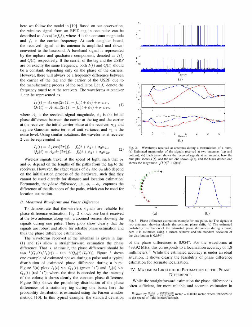
A critical test is whether the phase difference can be esti-mated reliably and whether the phase difference is discriminat-ing, i.e., whether it changes smoothly when the tag is moved.Figure 4 shows one of the experiments that demonstrates theseimportant features of the phase difference. In this experiment,
11We used fminsearch function; the Matlab is available fromhttp://www.mathworks.com.
(a)
(b)
Fig. 4. Phase differences on a surface patch. (a) Top-down view; (b) sideview to show the distribution in the three dimensional space.
we vary both the pan and tilt of the pan-tilt unit to cover aportion in the three dimensional space, which is similar toa portion of a sphere. For accurate measurements of phasedifference, we systematically move the tag; at each locationwhen the tag stops moving, we wait until we capture anactive burst of pulses and then we move the tag to the nextlocation. Figure 4 shows the phase difference on the surface;Fig. 4(a) gives a two-dimensional view of the surface to showthe detailed variations and Fig. 4(b) shows a three-dimensionalview. It is clear that the phase difference varies smoothly,depending on the three dimensional location of the tag. Inother words, the phase difference provides information of thetag position in the three dimensional space.
Figure 5 shows a one-dimensional localization experiment.Due to an equipment constraint (as we have only one USRPunit with complete configurations), the localization is onedimensional. In these particular experiments, we demonstratethe localization accuracy based on profiling. Here we fix thetilt angle and change the pan from -130◦ to 70◦ with a 25◦ stepsize. For each run, we generate a profile as in [13], i.e., thephase differences along the path, and use the phase differences
(a)
(b)
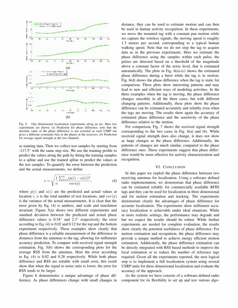
Fig. 5. One dimensional localization experiments along an arc. Here twoexperiments are shown. (a) Prediction for phase difference; note that theabsolute value of the phase difference is not essential as each USRP rungives a different systematic bias to the phases at the receivers; (b) Predictionfor average signal strength at the two channels.
as training data. Then we collect test samples by starting from-117.5◦ with the same step size. We use the training profile topredict the values along the path by fitting the training samplesto a spline and use the trained spline to predict the values atthe test samples. To quantify the error between the predictionand the actual measurements, we define
e =
√1n
∑ni=1(p(i)− a(i))2
var(a), (4)
where p(i) and a(i) are the predicted and actual values atlocation i, n is the total number of test locations, and var(a)is the variance of the actual measurements. It is clear that theerror given by Eq. (4) is unitless, and scale and translationinvariant. Figure 5(a) shows two different experiments andstandard deviation between the predicted and actual phasedifference values is 0.34◦ and 2.3◦ respectively; the erroraccording to Eq. (4) is 0.02 and 0.12 for the top and the bottomexperiment respectively. These examples show clearly thatphase difference is a reliable measurement of the difference indistances from the antennas to the tag, allowing for millimeteraccuracy prediction. To compare with received signal strengthestimation, Fig. 5(b) shows the corresponding plots for theaverage RSS from the antennas. Here the error accordingto Eq. (4) is 0.02 and 0.28 respectively. While both phasedifference and RSS are reliable with small error, this resultshow that when the signal to noise ratio is lower, the error forRSS tends to be larger.
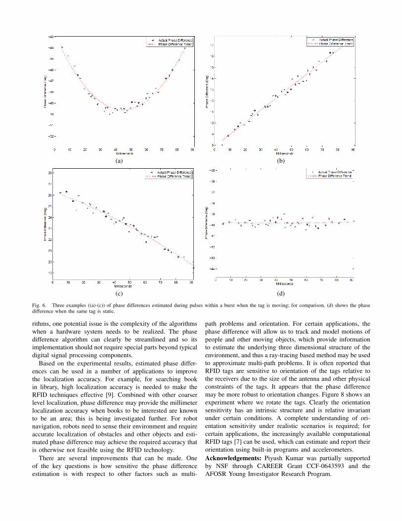
Figure 6 demonstrates a unique advantage of phase dif-ference. As phase differences change with small changes in
distance, they can be used to estimate motion and can thenbe used in human activity recognition. In these experiments,we move the mounted tag with a constant pan motion whilewe capture the wireless signals; the moving speed is roughly1.3 meters per second, corresponding to a typical humanwalking speed. Note that we do not stop the tag to acquiredata as in the previous experiments. Here we estimate thephase difference using the samples within each pulse; thepulses are detected based on a threshold of the magnitudeabove a constant factor of the noise level, that is estimatedautomatically. The plots in Fig. 6(a)-(c) shows the estimatedphase difference during a burst while the tag is in motion;Fig. 6(d) shows the phase difference when the tag is static forcomparison. These plots show interesting patterns and maylead to new and efficient ways of modeling activities. In thethree examples when the tag is moving, the phase differencechanges smoothly in all the three cases, but with differentchanging patterns. Additionally, these plots show the phasedifference can be estimated accurately and reliably even whenthe tags are moving. The results show again the accuracy ofestimated phase difference and the sensitivity of the phasedifference relative to the motion.
For comparison, Fig. 7 shows the received signal strengthcorresponding to the two cases in Fig. 6(a) and (b). Whilereceived signal strength does also change, it does not showas large changes as the phase difference. Additionally, thepatterns of changes are much similar, compared to the phasedifference ones. These experiments suggest that phase differ-ence would be more effective for activity characterization andrecognition.
VI. CONCLUSION
In this paper we exploit the phase difference between tworeceiving antennas for localization. Using a software definedradio implementation, we demonstrate that phase differencecan be estimated reliably for commercially available RFIDtags and they can be used for localization in three dimensionaland for motion estimation and tracking. The experimentsdemonstrate clearly the advantages of phase difference foraccurate localization. The experiments show millimeter accu-racy localization is achievable under ideal situations. Whilein more realistic settings, the performance may degrade andbut we expect the results should be robust. While furtherexperiments are needed for complete evaluation, the resultsshow clearly the potential usefulness of phase difference. Formotion estimation and recognition, the phase difference mayprovide a unique method to achieve energy efficient motionestimation. Additionally, the phase difference estimation canbe directly integrated with RSS based methods to improve thelocal estimation or to reduce the number of reference tagsrequired. Given all the experiments reported, the next logicalstep is to implement a full localization system using severalUSRP units for three dimensional localization and evaluate theaccuracy of the approach.
As the system we have consists of a software-defined radiocomponent for its flexibility to set up and test various algo-
(a) (b)
(c) (d)
Fig. 6. Three examples ((a)-(c)) of phase differences estimated during pulses within a burst when the tag is moving; for comparison, (d) shows the phasedifference when the same tag is static.
rithms, one potential issue is the complexity of the algorithmswhen a hardware system needs to be realized. The phasedifference algorithm can clearly be streamlined and so itsimplementation should not require special parts beyond typicaldigital signal processing components.
Based on the experimental results, estimated phase differ-ences can be used in a number of applications to improvethe localization accuracy. For example, for searching bookin library, high localization accuracy is needed to make theRFID techniques effective [9]. Combined with other coarserlevel localization, phase difference may provide the millimeterlocalization accuracy when books to be interested are knownto be an area; this is being investigated further. For robotnavigation, robots need to sense their environment and requireaccurate localization of obstacles and other objects and esti-mated phase difference may achieve the required accuracy thatis otherwise not feasible using the RFID technology.
There are several improvements that can be made. Oneof the key questions is how sensitive the phase differenceestimation is with respect to other factors such as multi-
path problems and orientation. For certain applications, thephase difference will allow us to track and model motions ofpeople and other moving objects, which provide informationto estimate the underlying three dimensional structure of theenvironment, and thus a ray-tracing based method may be usedto approximate multi-path problems. It is often reported thatRFID tags are sensitive to orientation of the tags relative tothe receivers due to the size of the antenna and other physicalconstraints of the tags. It appears that the phase differencemay be more robust to orientation changes. Figure 8 shows anexperiment where we rotate the tags. Clearly the orientationsensitivity has an intrinsic structure and is relative invariantunder certain conditions. A complete understanding of ori-entation sensitivity under realistic scenarios is required; forcertain applications, the increasingly available computationalRFID tags [7] can be used, which can estimate and report theirorientation using built-in programs and accelerometers.Acknowledgements: Piyush Kumar was partially supportedby NSF through CAREER Grant CCF-0643593 and theAFOSR Young Investigator Research Program.
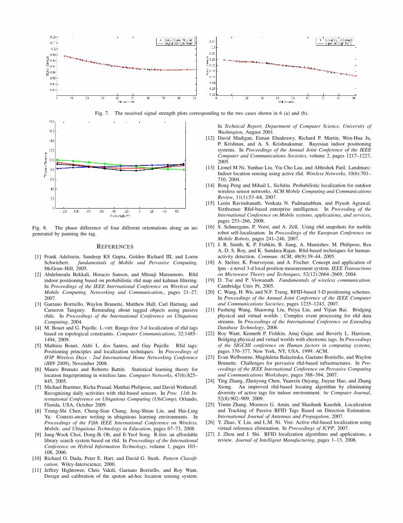
Fig. 7. The received signal strength plots corresponding to the two cases shown in 6 (a) and (b).
Fig. 8. The phase difference of four different orientations along an arcgenerated by panning the tag.
REFERENCES
[1] Frank Adelstein, Sandeep KS Gupta, Golden Richard III, and LorenSchwiebert. fundamentals of Mobile and Pervasive Computing.McGraw-Hill, 2005.
[2] Abdelmoula Bekkali, Horacio Sanson, and Mitsuji Matsumoto. Rfidindoor positioning based on probabilistic rfid map and kalman filtering.In Proceedings of the IEEE International Conference on Wireless andMobile Computing, Networking and Communication,, pages 21–27,2007.
[3] Gaetano Borriello, Waylon Brunette, Matthew Hall, Carl Hartung, andCameron Tangney. Reminding about tagged objects using passiverfids. In Proceedings of the International Conference on UbiquitousComputing, 2004.
[4] M. Bouet and G. Pujolle. L-virt: Range-free 3-d localization of rfid tagsbased on topological constraints. Computer Communications, 32:1485–1494, 2009.
[5] Mathieu Bouet, Aldri L. dos Santos, and Guy Pujolle. Rfid tags:Positioning principles and localization techniques. In Proceedings ofIFIP Wireless Days - 2nd International Home Networking Conference(IHN 2008), November 2008.
[6] Mauro Brunato and Roberto Battiti. Statistical learning theory forlocation fingerprinting in wireless lans. Computer Networks, 47(6):825–845, 2005.
[7] Michael Buettner, Richa Prasad, Matthai Philipose, and David Wetherall.Recognizing daily activities with rfid-based sensors. In Proc. 11th In-ternational Conference on Ubiquitous Computing (UbiComp), Orlando,Florida, USA, October 2009.
[8] Tzung-Shi Chen, Cheng-Sian Chang, Jeng-Shian Lin, and Hui-LingYu. Context-aware writing in ubiquitous learning environments. InProceedings of the Fifth IEEE International Conference on Wireless,Mobile, and Ubiquitous Technology in Education, pages 67–73, 2008.
[9] Jung-Wook Choi, Dong-Ik Oh, and Il-Yeol Song. R-lim: an affordablelibrary search system based on rfid. In Proceedings of the InternationalConference on Hybrid Information Technology, volume 1, pages 103–108, 2006.
[10] Richard O. Duda, Peter E. Hart, and David G. Stork. Pattern Classifi-cation. Wiley-Interscience, 2000.
[11] Jeffrey Hightower, Chris Vakili, Gaetano Borriello, and Roy Want.Design and calibration of the spoton ad-hoc location sensing system.
In Technical Report, Department of Computer Science, University ofWashington, August 2001.
[12] David Madigan, Eiman Elnahrawy, Richard P. Martin, Wen-Hua Ju,P. Krishnan, and A. S. Krishnakumar. Bayesian indoor positioningsystems. In Proceedings of the Annual Joint Conference of the IEEEComputer and Communications Societies, volume 2, pages 1217–1227,2005.
[13] Lionel M Ni, Yunhao Liu, Yiu Cho Lau, and Abhishek Patil. Landmarc:Indoor location sensing using active rfid. Wireless Networks, 10(6):701–710, 2004.
[14] Rong Peng and Mihail L. Sichitiu. Probabilistic localization for outdoorwireless sensor networks. ACM Mobile Computing and CommunicationsReview, 11(1):53–64, 2007.
[15] Lenin Ravindranath, Venkata N. Padmanabhan, and Piyush Agrawal.Sixthsense: Rfid-based enterprise intelligence. In Proceeding of theInternational Conference on Mobile systems, applications, and services,pages 253–266, 2008.
[16] S. Schneegans, P. Vorst, and A. Zell. Using rfid snapshots for mobilerobot self-localization. In Proceedings of the European Conference onMobile Robots, pages 241–246, 2007.
[17] J. R. Smith, K. P. Fishkin, B. Jiang, A. Mamishev, M. Philipose, ReaA, D, S. Roy, and K. Sundara-Rajan. Rfid-based techniques for human-activity detection. Commun. ACM, 48(9):39–44, 2005.
[18] A. Stelzer, K. Pourvoyeur, and A. Fischer. Concept and application oflpm - a novel 3-d local position measurement system. IEEE Transactionson Microwave Theory and Techniques, 52(12):2664–2669, 2004.
[19] D. Tse and P. Viswanath. Fundamentals of wireless communication.Cambridge Univ Pr, 2005.
[20] C. Wang, H. Wu, and N.F. Tzeng. RFID-based 3-D positioning schemes.In Proceedings of the Annual Joint Conference of the IEEE Computerand Communications Societies, pages 1235–1243, 2007.
[21] Fusheng Wang, Shaorong Liu, Peiya Liu, and Yijian Bai. Bridgingphysical and virtual worlds : Complex event processing for rfid datastreams. In Proceedings of the International Conference on ExtendingDatabase Technology, 2006.
[22] Roy Want, Kenneth P. Fishkin, Anuj Gujar, and Beverly L. Harrison.Bridging physical and virtual worlds with electronic tags. In Proceedingsof the SIGCHI conference on Human factors in computing systems,pages 370–377, New York, NY, USA, 1999. ACM.
[23] Evan Welbourne, Magdalena Balazinska, Gaetano Borriello, and WaylonBrunette. Challenges for pervasive rfid-based infrastructures. In Pro-ceedings of the IEEE International Conference on Pervasive Computingand Communications Workshops, pages 388–394, 2007.
[24] Ting Zhang, Zhenyong Chen, Yuanxin Ouyang, Jiuyue Hao, and ZhangXiong. An improved rfid-based locating algorithm by eliminatingdiversity of active tags for indoor environment. he Computer Journal,52(8):902–909, 2009.
[25] Yimin Zhang, Moeness G. Amin, and Shashank Kaushik. Localizationand Tracking of Passive RFID Tags Based on Direction Estimation.International Journal of Antennas and Propagation, 2007.
[26] Y. Zhao, Y. Liu, and L.M. Ni. Vire: Active rfid-based localization usingvirtual reference elimination. In Proceedings of ICPP, 2007.
[27] J. Zhou and J. Shi. RFID localization algorithms and applications, areview. Journal of Intelligent Manufacturing, pages 1–13, 2008.


![BVIRE improved algorithm for indoor localization based on RFID … · LANDMARC algorithm is one of the most well-known indoor localization techniques using active RFID tags [3]. When](https://img.pdfslide.us/doc/110x75/60a28997bc0657765832dc36/bvire-improved-algorithm-for-indoor-localization-based-on-rfid-landmarc-algorithm.jpg)