Embed Size (px)
Citation preview

Atlanta (Monroe) GA 770-267-3787
[email protected] www.gpmhydraulic.com
WHAT YOU DON’T KNOW
ABOUT ACCUMULATORS CAN KILL YOU!

What You Don’t Know About Hydraulic Accumulators Can Kill You
TABLE OF CONTENTS
Accumulator Function and Dangers of Pre-Charging with Oxygen 1
Safety Procedure for Pre-Charging an Accumulator 2 - 4 Checking the Pre-Charge Hydraulically and
Proper Gauge Location 4, 5 Operation of the Piston Accumulator 5 - 8 Maintenance Safety Procedures of
Removing the Piston 9 Operation of the Bladder Accumulator 10 - 11 Maintenance Safety Procedures for Removing and
Replacing the Bladder 11 - 13 Accumulator Dump Valves 14 – 16 Accumulator Safety Procedures When Working on
or Around the Machine 17 - 18
Accumulators And Flow Controls
Accumulators
Hydraulic accumulators are used to storepressurized hydraulic fluid. The accumulatorperforms the same function in a hydrauliccircuit that a capacitor does in an electricalcircuit. Dry nitrogen is used to “pre-charge”one side of the accumulator. A piston or sometype of rubber element (bladder or diaphragm)is used to separate the hydraulic fluid and thenitrogen.
Accumulators primarily will perform two functions in the hydraulic circuit:
1) Supply additional oil flow to the system at a very fast rate. Theaccumulator amd pump volumes are combined together to rapidlycycle hydraulic cylnders.
2) Absorb shock. Hydraulic oil flows through the system at a rate ofapproximately 20 feet per second. When a cylinder piston bottomsout or a valve is rapidly closed, shock occurs in the system.
Dry Nitrogen
Dry nitrogen is used to pre-chargeaccumulators because it is an inert gas.Although any inert gas can be used,nitrogen is cheaper because it is morereadily available. 78% of the earth’satmosphere is nitrogen, 21% oxygen, and1% is made up of Argon and other gases.An inert gas will not react readily withother chemicals. Oxygen orcompressed air should never be usedto pre-charge an accumulator. Asoxygen is compressed it heats up and cancause a fire or explosion when mixing withthe hydraulic oil.
Hydraulic Accumulator Maintenance & Safety Page 1
Accumulators

Charging the Accumulator with Nitrogen
In order for the accumulator to deliver the right amount of oil, the nitrogenpre-charge pressure must be correct. A good rule of thumb is topre-charge to half the maximum system pressure. In systems usingpressure compensating pumps, the maximum system pressure is determinedby the compensator setting. The relief valve setting determines maximumsystem pressure in fixed displacement pump circuits (see pg. 20). This rule ofthumb applies only to accumulators used for volume. Accumulators used forshock require a different pre-charge and are discussed later in this section.
In the example shown, thecompensator settingdetermines the maximumsystem pressure. Theaccumulator pre-charge inthis system should be ½ of2000 PSI or 1000 PSI.
To charge the accumulator,the pressure on the oil sideshould be bled down to 0 PSI.In the example circuit, valveNo. 1 should be closed first,then valve No. 2 should beopened. If the hydraulicpump is turned off, valve No.2 should still be openedallowing the oil pressure todrop to 0 PSI.
Once the hydraulic pressure is bled to 0 PSI(Figure 1), the protective valve cover on top ofthe accumulator can be removed. The gaugeand charging rig are then installed onto theaccumulator gas valve.
Page 2 Hydraulic Accumulator Maintenance & Safety
Accumulators

With the bleeder valve closed, turn the gas chuck handle clockwise. Thepre-charge pressure should then be indicated on the pressure gauge.Cracking the bleeder valve open will relieve the nitrogen pressure toatmosphere if overcharged. Before charging a piston accumulator, bleed allthe nitrogen off, as there may be oil build up on top of the piston due tobypassing(see pg. 12).
To charge with nitrogen turn the gas chuck handle counterclockwise. To ventthe pressure out of the charging assembly open and then re-close the bleedervalve. Connect the hose from the nitrogen bottle to the charging rig.
Hydraulic Accumulator Maintenance & Safety Page 3
Accumulators
Figure 1

The bottles normally are originally pre-charged to 2200 PSI. With the nitrogenbottle gas valve closed, turn the gas chuck handle clockwise to depress theaccumulator gas valve. Gradually open the valve on the nitrogen bottle. Setthe regulator on the nitrogen bottle to the desired pressure. Close the nitrogenbottle gas valve when pre-charged to the proper pressure. After pre-charging,turn the gas chuck handle counterclockwise and open the bleeder valve torelieve the pressure in the hose. The hose and charging rig can now beremoved. The accumulator gas valve cover should be replaced.
Checking the Nitrogen Pre-charge Hydraulically
Instead of attaching thecharging rig for checking thepre-charge, a hydraulicmethod is available. Whenthe pump is turned off,pressure is locked in thesystem.
Page 4 Hydraulic Accumlator Maintenance & Safety
Accumulators

Open the No. 2 manual dumpvalve a small amount. Thepressure in the system willslowly drop. The pressure willdrop to a point, then rapidly 0PSI. The pressure that itrapidly drops to 0 is thepre-charge pressure.
Types of Accumulators
PistonThe piston accumulator is similar to a cylinderwithout the rod. The piston separates thenitrogen and oil. Piston types are usually usedwhen larger accumulators are required.Although it can be mounted in any position, avertical mounting is better. If mountedhorizontal, the barrel will wear on the bottomside because of the weight of the piston andcontamination.
Hydraulic Accumulator Maintenance & Safety Page 5
Accumulators

In the example circuit, the pump is off and the ¼” hand valve is open. Thenitrogen pre-charge pressure has forced the piston all the way to the bottom.Any oil in the accumulator is drained to tank through the ¼” dump valve.
Page 6 Hydraulic Accumulator Maintenance & Safety
Accumulators

With the ¼” manual dump valve closed and the pump turned on, the pumpvolume will begin filling the accumulator. As the accumulator fills, the drynitrogen is compressed. The pump will continue to fill and pressurize theaccumulator until both the nitrogen and hydraulic pressures are 2000 PSI(pump compensator setting). At this point the accumulator is fully chargedand the pump will compensate.
Hydraulic Accumulator Maintenance & Safety Page 7
Accumulators

When the directional valve is energized in the “A” position, pressure in thesystem will drop. The pressure drops because it takes less than 2000 PSI tomove the load. The dry nitrogen forces the oil out of the accumulatorcombining it with the pump volume. The oil is ported through the directionalvalve to move the load. When the cylinder piston fully bottoms out or thedirectional valve is de-energized the pump will again fill the accumulator.
Page 8 Hydraulic Accumulator Maintenance & Safety
Accumulators

Bypassing Test and Piston RemovalTo check for bypassing and to inspectthe piston, install the charging rig. Foreasy removal of the piston it should beforced to the top. The followingprocedures will accomplish this easilyand safely.
1. With the pump on, open the No. 3 bleeder valve on the charging rig.The nitrogen should be forced out of the top of the piston and the nitrogenpressure should drop to 0 PSI. On most charging rigs, the bleeder valve canbe removed and a hose put in its place to prevent an oil spill.
2. Close the No. 1 isolationvalve. The pump can also beturned off at this time.
3. Open the ¼” manual dumpvalve (No. 2). Hydraulic pressurein the accumulator will bleed backto tank. The piston should remainat the top due to the friction of theseals.
4. Remove the charging rig andthe top of the accumulator. Apuller can then be attached to thepiston for removal.
Hydraulic Accumulator Maintenance & Safety Page 9
Accumulators

Bladder Accumulator
The bladder accumulator uses a thickrubber type balloon as the device thatseparates the oil from the nitrogen.Drawing “A” shows the bladder filled withnitrogen (1000 PSI). The expandedbladder is holding the poppet valveclosed. The purpose of the poppet valveis to prevent the bladder from protrudinginto the piping and system.
Page 10 Hydraulic Accumulator Maintenance & Safety
Accumulators
Poppet Valve
Bladder

In drawing “B”, the hydraulic pressure hascompressed the nitrogen to the maximumsystem pressure (2000 PSI). Thehydraulic and nitrogen pressures areequal at this point.
When the directional valves areenergized to extend the cylinders (C), thehydraulic pressure drops. The nitrogen inthe bladder forces the fluid out at a highrate of flow. In normal operation thebladder should not contact the poppetvalve.
Hyadrulic Accumulator Maintenance Safety Page 11
Accumulators
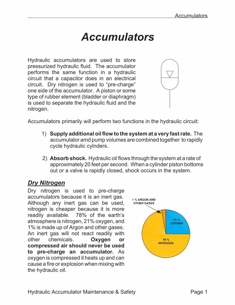
Replacing the Bladder for Bottom Repairable AccumulatorsInstall the charging rig to the bladder valve and release the nitrogenpre-charge. Insure that the hydraulic pumps have been locked out and thepressure has been bled down to 0 PSI prior to removing the accumulator fromthe machine. All oil should be drained before disconnecting the hydrauliclines.
1) Remove the accumulator andplace on a work bench. Installthe charging rig again to insurethat the precharge has beenreleased. It is always a goodidea to remove the valve stemfrom the bladder. In some caseswhen the bladder ruptures anddeflates, it will fold over insidetrapping a small amount ofnitrogen pressure.
2) Remove the nut, washersand the O-ring on the poppetvalve assembly. You will alsoneed to remove the smaller nuton the bladder.
3) The poppet will have to be pushed inside the shell to remove the retainerring. Sometimes the retainer will stick to the accumulator shell or the poppetvalve. The retainer is designed to fold in half for removal. The retainer ring willhave to be removed before the poppet valve.
Page 12 Hydraulic Accumulator Maintenance & Safety
Accumulators
Removing the Poppet Valve
Poppet Valve Assembly

4) Once the poppet valve isremoved, the bladder can beremoved as well. A 5-gallonbucket can be used to catchthe oil that is inside theruptured bladder.
5) Prior to installing a new bladder, theinner shell should be cleaned. Also,inspect the old retainer ring for damage.
It is always best to replace the oldretainer ring with a new one. There is agood possibility that the hydraulic systemhas over heated prior to removal. Heatcauses rubber to harden and get brittle.
6) The inner shell of the accumulator and the bladder should be lubricated withhydraulic oil. This provides a slippery surface that will make it a little easier toinstall the new bladder. A threaded tool can be attached to the bladder to helppull the bladder into the shell.
7) The poppet valve assembly can now be installed in the reverse order.Never pre-charge the accumulator in the shop. Install it first! Slightly open thenitrogen bottle valve when initially pre-charging the first 50 PSI. Otherwise thecold nitrogen introduced quickly can cause the rubber to become brittle andrupture.
Hydraulic Accumulator Maintenance & Safety Page 13
Accumulators
Removing the Bladder
Damaged Retainer Ring

Accumulator Dump Valves
A circuit using a hydraulic accumulator must have a method of bleeding thepressure down when the system is turned off. All accumulator systems shoulduse a manual or automatic dump valve to accomplish this. If the pressure isnot bled down then the accumulator will remain charged over a period of time.Prior to working on the system you should verify that the pressure isbled down by observing the pressure gauge when the machine is turnedoff.
In some cases, the electric motor is turned off, however control power to thesystem directional valves remains on. If a photocell, limit switch, or proximityswitch is made accidentally, the directional valve can shift causing the cylinderto move.
Manual Dump ValveThe manual dump valve isnormally a small valve, ¼” orless. Anytime the pump isturned off and maintenance isperformed, the valve shouldbe opened.
Page 14 Hydraulic Accumulator Maintenance & Safety
Accumulators

Solenoid Operated DumpValveThe solenoid on the normallyopen dump valve is usually wiredin to the electric motor starter.When the motor is started thevalve will shift closed, blockingflow back to the tank. When thepump is turned off, electricalpower is removed from the dumpvalve solenoid. The valve spoolwill then spring return to the openposition. The pressurized fluid inthe accumulator willautomatically bleed to tankthrough the dump valve.
Pilot to Close Check ValveWhen the pump is turned on,pilot pressure plus the springpressure holds the valve closed.Flow is then blocked back totank. When the pump is turnedoff, pressure in the pilot line willbleed down through the internalclearances inside the pump.Pressurized fluid in theaccumulator will shift the valveopen, dumping the oil back totank.
Hydraulic Accumulator Maintenance & Safety Page 15
Accumulators
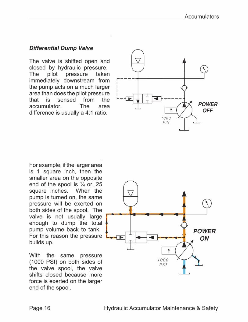
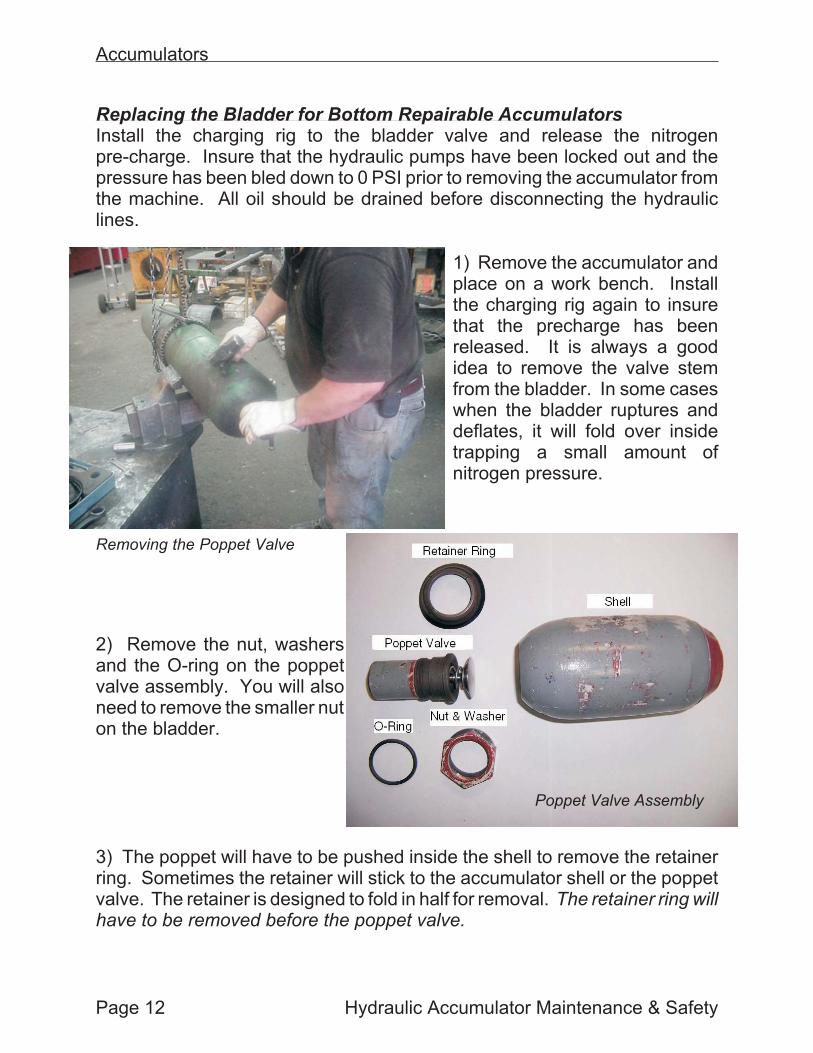
Differential Dump Valve
The valve is shifted open andclosed by hydraulic pressure.The pilot pressure takenimmediately downstream fromthe pump acts on a much largerarea than does the pilot pressurethat is sensed from theaccumulator. The areadifference is usually a 4:1 ratio.
For example, if the larger areais 1 square inch, then thesmaller area on the oppositeend of the spool is ¼ or .25square inches. When thepump is turned on, the samepressure will be exerted onboth sides of the spool. Thevalve is not usually largeenough to dump the totalpump volume back to tank.For this reason the pressurebuilds up.
With the same pressure(1000 PSI) on both sides ofthe valve spool, the valveshifts closed because moreforce is exerted on the largerend of the spool.
Page 16 Hydraulic Accumulator Maintenance & Safety
Accumulators

Force to Shift Closed = PSI x Area
Force to Shift Closed = 1000 PSI x 1 square inch
Force to Shift Closed = 1000 lbs force
Force on Opposite End = 1000 PSI x .25 square inches
Force on Opposite End = 250 lbs force
When the pump is turned off, the valve shifts back into the open positionshown in the Power Off condition. The oil in the accumulator then returns backto tank.
Accumulator Safety
The accumulator is the most dangerous hydraulic component in the system,simply because it is a source of stored energy. Several safety proceduresshould be followed when working with accumulators. Follow all ZES lock out.
• LOCK OUT the pump, Then make sure the pressure is bled downout of the hydraulic system and accumulator before working on oraround the machine.
• Watch the pressure gauge when the system is turned off. If anautomatic dump valve is used, then the pressure should graduallydrop to 0 PSI. If the pressure is not bled down, locate the manualdump valve. Open the valve and recheck the pressure. If it is bleddown, LOCK the valve into the open position. In a quiet area, youcan hear the pressurized fluid returning to tank through the valve.
Hydraulic Accumulator Maintenance & Safety Page 17
Accumulators

• Release the nitrogen pressure with a charging rig before removingthe accumulator from the system. If the protective cap cannot beremoved, do not cut it off with a torch. The compressed nitrogencan be released violently, causing possible hearing and otherphysical damage.
• Always pre-charge the accumulator once installed on the machine.NEVER pre-charge an accumulator in the shop and carry it into theplant. NEVER pre-charge with nitrogen pressure above themaximum pressure of the accumulator. The maximum pressure isstamped on the outer housing of the accumulator.
• Make sure accumulators are properly clamped.
Page 18 Hydraulic Accumulator Maintenance & Safety
Accumulators