Embed Size (px)
Citation preview

AccuCore STA Introduction Training
AccuCore Static Timing Analysis Commands and Concepts

AccuCore STA Introduction Training
AccuCore Static Timing Analysis
High Performance SoC Timing Solution Levels of Design Abstraction History of Digital Functional Verification Definitions of Key STA Terminology Key capabilities of AccuCore Block-level STA Key Capabilities of Full Chip STA Using AccuCore STA in a Standalone Flow Using AccuCore STA in a Unified Flow Basic AccuCore STA Operations
2
AccuCore STA Introduction Training
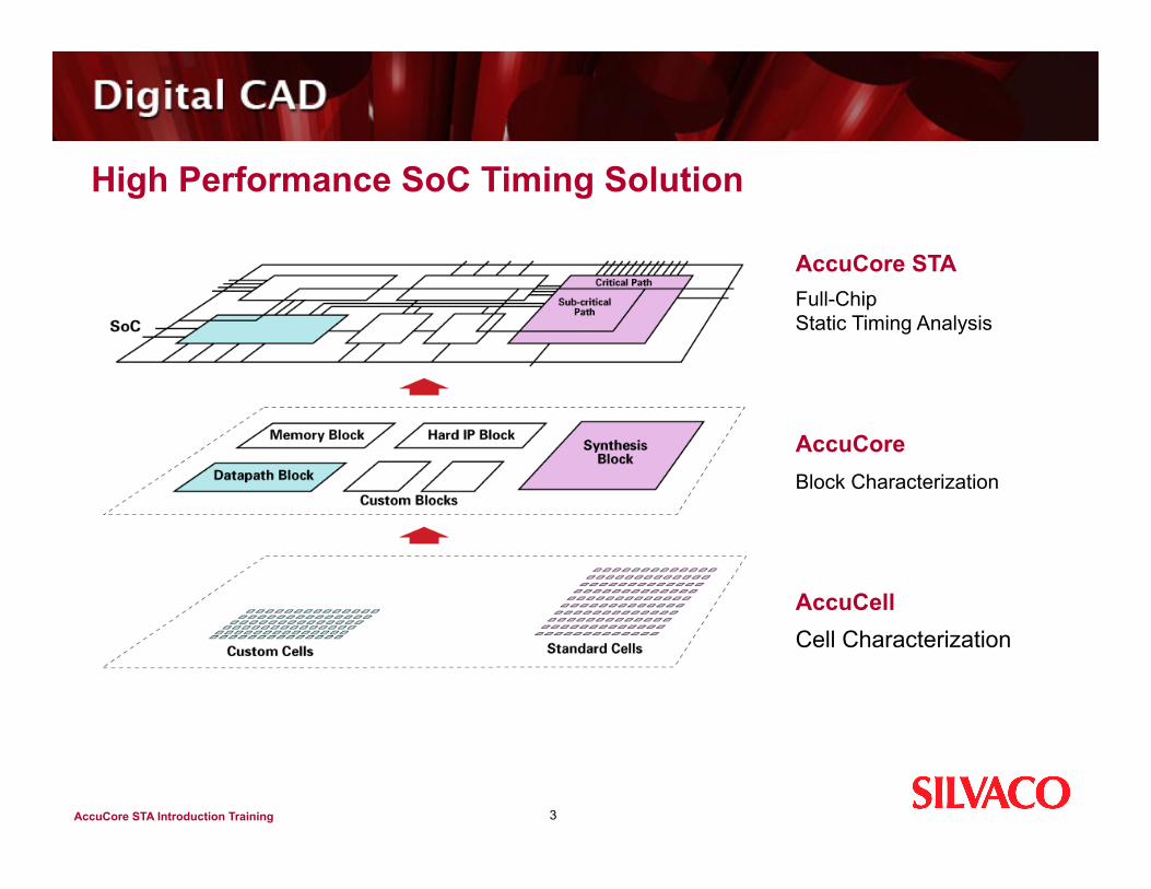
High Performance SoC Timing Solution
3
AccuCore STA Full-Chip Static Timing Analysis
AccuCore Block Characterization
AccuCell Cell Characterization

AccuCore STA Introduction Training
Static Timing Analysis and Characterization in Your Design Flow
4
Silvaco supports both a top-down and bottom-up timing strategy to ensure accurate results and optimize timing closure
Custom Block Design
Timing Verification
Layout
Characterization Block Model
Timing Verification/
Timing Closure
Place & Route Integration
Gate-level Verification
Logic Synthesis
RTL Verification
RTL Design
Characterization Block Model
Layout
Timing Verification
Embedded Memory Design
Characterization Block Model
Hard IP Design
Characterization Block Model
Layout
Timing/Power Verification
Cell Library Design

AccuCore STA Introduction Training
In-Circuit Characterization Engine
5
Timing Model Generation
Automatic Circuit Partitioning Circuit Functional Extraction Automatic Vector Generation Ultra-Fast / Accurate Spice
Functional Model
Generation
Static Timing Analysis
Power Characterization
Tool Performance: Fastest Characterization Incremental Analysis
Engineering Performance: Automation Ease of use
Design Performance: Highest accuracy Complete modeling

AccuCore STA Introduction Training
Scalable Characterization Solution
6
Full-Chip Environment
Timing Models .lib (all paths) .lib (compressed) .lib (black box)
Functional Models Verilog (gate level)
Power Models .lib (standard cell)
Silvaco’s characterization technology scales-up from standard cells to hard IP cores for use in Full-Chip STA

AccuCore STA Introduction Training
Digital Circuit Verification Methods
Non-Hierarchical True SPICE Simulation Highest accuracy, but with limited capacity, too slow, large manual vector
generation effort and will not achieve 100% coverage Gate Level Simulation with SDF Back Annotation
Requires expensive dedicated emulation/acceleration hardware to simulate in reasonable timeframes
Requires large manual vector generation effort and will not achieve 100% coverage
7

AccuCore STA Introduction Training
Digital Circuit Verification Methods (cont’d)
RTL Simulation with Formal Verification and Static Timing Analysis (STA) Dependent on some manual manual vector generation and has reduced timing
accuracy for advanced designs and advanced processes Limitations in design style for high performance (dynamic logic, asynchronous) Requires detailed exhaustive library characterization effort
Switch Level/Fast SPICE Simulation Requires detailed exhaustive library characterization effort Adequate capacity but reduced accuracy, requires large manual vector
generation effort and will not achieve 100% coverage
- 8 -

AccuCore STA Introduction Training
Static Timing Analysis (STA)
Static Timing Analysis is a method of computing the expected timing of a digital circuit without requiring simulation In a synchronous digital system, data is supposed to move in lockstep,
advancing one stage on each tick of the clock signal This is enforced by synchronizing elements such as flip-flops or latches,
which copy their input to their output when instructed to do so by the clock On first order, only two kinds of timing errors are possible in such a system:
A hold time violation, when a signal arrives too early, and advances one clock cycle before it should
A setup time violation, when a signal arrives too late, and misses the time when it should advance
9

AccuCore STA Introduction Training
Static Timing Analysis (STA) (cont’d)
The time when a signal arrives can vary due to many reasons The input data may vary The circuit may perform different operations The temperature and voltage may change There are:
lot-to-lot wafer-to-wafer die-to-die manufacturing differences
The main goal of static timing analysis is to verify that despite these possible variations, all signals will arrive neither too early nor too late, and hence proper circuit operation can be assured
- 10 -

AccuCore STA Introduction Training
Definitions of Key STA Terminology
The critical path is defined as the path between an input and an output with the maximum delay Once the circuit timing has been computed by one of techniques below, the
critical path can easily found by using a traceback method The arrival time of a signal is the time elapsed for a signal to arrive at a
certain point The reference, or time 0.0, is often taken as the arrival time of a clock signal To calculate the arrival time, delay calculation of all the component of the path
will be required Arrival times, and indeed almost all times in timing analysis, are normally kept
as a pair of values the earliest possible time at which a signal can change, and the latest
11

AccuCore STA Introduction Training
Definitions of Key STA Terminology (cont’d)
Another useful concept is required time This is the latest time at which a signal can arrive without making the
clock cycle longer than desired The computation of the required time proceeds as follows At each primary output, the required times for rise/fall are set according
to the specifications provided to the circuit Next, a backward topological traversal is carried out
processing each gate when the required times at all of its fanouts are known
The slack associated with each connection is the difference between the required time and the arrival time A positive slack at a node implies that the arrival time at that node may
be increased by without affecting the overall delay of the circuit Conversely, negative slack implies that a path is too slow
must be sped up if the whole circuit is to work at the desired speed
- 12 -

AccuCore STA Introduction Training
AccuCore Static Timing Analyzer (STA)
AccuCore Static Timing Analyzer (STA) is a hierarchical gate level analyzer with full chip capabilities
It handles both sequential and combinational devices and can be used either as a standalone analyzer or as part of a unified characterization flow
In a standalone flow, STA operates independently of characterization reading both a verilog netlist and multiple timing libraries in Liberty format
It can also read interconnect parasitic data in DSPF or SDF formats when used in a unified flow the process includes characterization of the partitioned cells creation of a verilog interconnect netlist And Liberty formatted timing libraries that eventually feed back into STA
Both flows enable full chip analysis of custom and ASIC blocks in a single run
13

AccuCore STA Introduction Training
AccuCore Block Level STA Capabilities
Path Tracing Finds the longest and shortest paths through the design Traces critical and subcritical paths separately Uses options to direct and limit search paths to areas of interest Uses element function to propagate constants Contains elaborate path-blocking capabilities Accommodates clock propagation
14

AccuCore STA Introduction Training
AccuCore Block Level STA Capabilities (cont’d)
Timing verification Verifies timing of flip-flops, latches, domino logic, dynamic elements,
muxes, and tristate elements; Analyzes gated clocks and designs with clocks of varying frequencies; Performs data-to-data timing checks for arbitrary nets in the design; Accommodates multicycle paths Performs customized timing checks for gated clocks and sequential
elements; Back annotates interconnect parasitics information using DSPF and
SDF formats
- 15 -

AccuCore STA Introduction Training
AccuCore Block Level STA Capabilities
Reporting Reports longest and shortest paths Includes clock paths and data paths in timing check reports Reports path-based net-slack and gate pin slack Provides data on the worst arrival and required time for both the net
and gate pins Reports the worst falling and rising arrival time on the net
Delay calculation Supports conditional delays Supports scalar, one-dimensional and 2-dimensional tables of slope
and delay values Supports max and min delay values with different vectors from the
Silvaco library
16

AccuCore STA Introduction Training
AccuCore Block Level STA Capabilities (cont’d)
SPICE deck generation Generates SPICE deck of critical paths Generates SPICE deck of a clock tree
Modeling Generates multiple models of the analyzed design
- 17 -

AccuCore STA Introduction Training
AccuCore Full-Chip Level STA Capabilities (1 of 3)
STA Reads hierarchical Verilog netlist Reads multiple libraries in the Silvaco and standard industry synthesis formats Back-annotates interconnect parasitics information using transistor or gate level
DSPF and SDF formats Considers black box and compressed models Enables constraint management
Modeling Generates black box timing model Generates compressed models, hiding details of the combinational paths Generates interface compressed model to enable gate level DSPF back
annotation at the full chip level Propagates slope tables during compressed model generation Generates interface models with a detailed view of interface logic
18

AccuCore STA Introduction Training
AccuCore Full-Chip Level STA Capabilities (3 of 3)
Block constraint generation and slack allocation Generates external timing and load gate pin or net based constraints for
hierarchical blocks from full chip timing analysis Performs driver-receiver slack allocation based on user directives
Clock skew analysis Allows the user to specify uncertainty, i.e. a skew relationship between
clock nets Uses clock skew to find timing violations
19

AccuCore STA Introduction Training
AccuCore Full-Chip Level STA Capabilities (2 of 3)
Debugging capabilities Provides complete information about clock propagation and clock
waveforms Provides netlist, library, and analysis verification commands
Application Program Interface (API) Enables access to STA databases through TCL functions Allows for the creation of customized reports Allows for the creation of timing models in user-defined formats
- 20 -

AccuCore STA Introduction Training
Using STA in a Standalone Flow
21
STEP 1: Creation of the Configuration File Create configuration file
STEP 2: Creation of a TCL Script Call the configuration file with the sta_read_cfg Library Verification – verify timing accuracy of library of cells Verify connectivity between verilog netlist and cell library with sta_verify_netlist Commands to find critical paths and verify critical and subcritical setup and hold timing checks Validate the script with verify_checks and report_checks
STEP 3: Clock Verification Clock propagation verification with find_paths, print_clock_waveforms and report_warnings -all
STEP 4: Analysis Limit analysis to specific nets, analyze false paths and subcritical nets
STEP 5: Evaluation of Results Generate statistics and verify with SPICE using print_spice_paths
AccuCore STA Introduction Training
STA in a Unified Flow
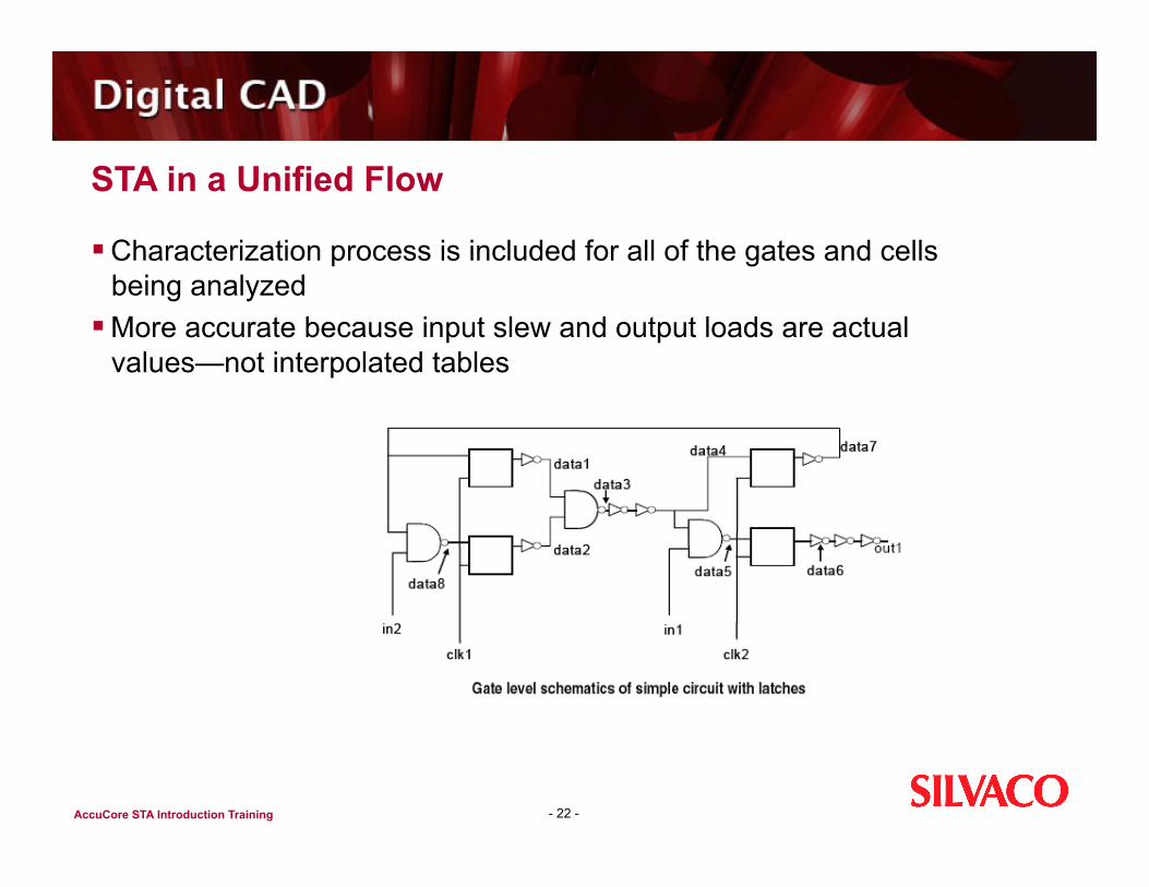
Characterization process is included for all of the gates and cells being analyzed
More accurate because input slew and output loads are actual values—not interpolated tables
- 22 -

AccuCore STA Introduction Training
Using STA in a Unified Flow
- 23 -
STEP 1: Creation of the Configuration File Create configuration file with commands to characterize the circuit using in_file, lib_cmd, do_sta, clock_time, input_time, output_time
Validate the configuration file with sta_read_cfg
STEP 2: Creation of a TCL Script Commands to find critical paths and verify critical and subcritical setup and hold timing check
with gen_model file.cfg added to initialize characterization
STEP 3: Running AccuCore with STA Include gen_model file.cfg to analyze the block, partition the circuit into design clusters,
characterize them, and create the library
STEP 4: Evaluation of Preliminary STA Results Analyze default report and run additional reports by adding commands to the TCL file and .cfg
file
STEP 5: Examining the User-requested Reports Use verify_checks to evaluate timing constraints on latch inputs and primary outputs Note that a negative margin indicates a violation
AccuCore STA Introduction Training
Outline for Basic STA Operations
24
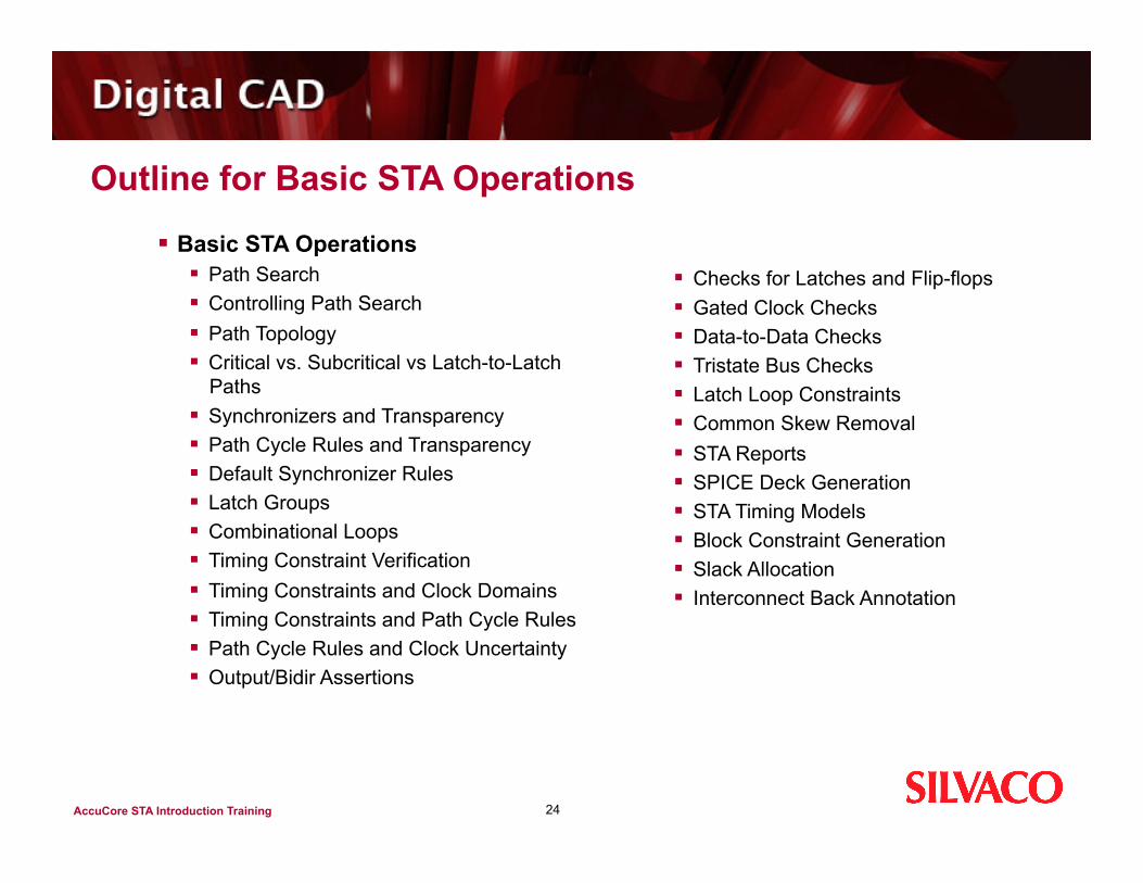
Basic STA Operations Path Search Controlling Path Search Path Topology Critical vs. Subcritical vs Latch-to-Latch
Paths Synchronizers and Transparency Path Cycle Rules and Transparency Default Synchronizer Rules Latch Groups Combinational Loops Timing Constraint Verification Timing Constraints and Clock Domains Timing Constraints and Path Cycle Rules Path Cycle Rules and Clock Uncertainty Output/Bidir Assertions
Checks for Latches and Flip-flops Gated Clock Checks Data-to-Data Checks Tristate Bus Checks Latch Loop Constraints Common Skew Removal STA Reports SPICE Deck Generation STA Timing Models Block Constraint Generation Slack Allocation Interconnect Back Annotation
AccuCore STA Introduction Training
Path Search
Ability to determine arrival time and the required time of all nets and use the information to prune the search space
Ability to locate all paths that contribute to a timing violation thereby avoiding the multi-layer "onion peeling“ problem when implementing a fix
Full modeling of transparency for latches and other synchronizer types Ability to handle domino gates in combination with AccuCore
characterization Ability to manually control searches through blocking, constant
propagation, and cycle specifications
25

AccuCore STA Introduction Training
Path Search (cont’d)
- 26 -
The two primary commands used with path search are: find_paths - For path-only searches with the results sorted according to path
endtime or path length verify_checks - For determining the errors/margins of timing constraints
and the corresponding clock and data paths The results are sorted according to error/margin value
AccuCore STA Introduction Training
Controlling Path Search
- 27 -
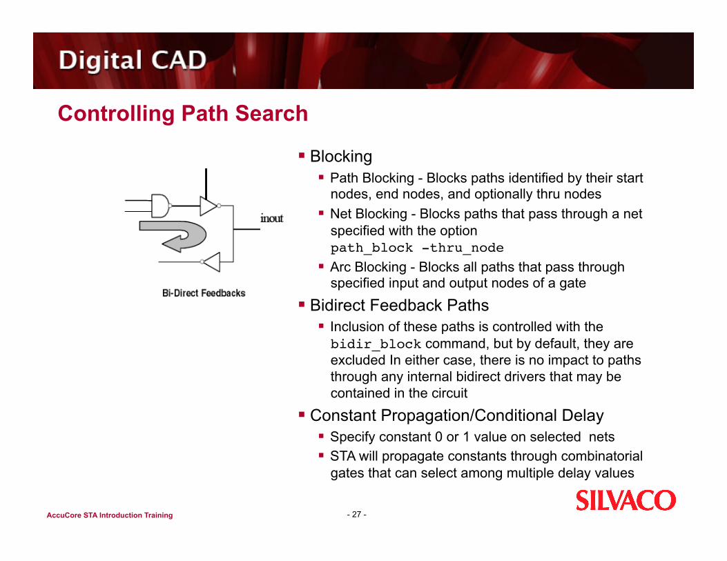
Blocking Path Blocking - Blocks paths identified by their start
nodes, end nodes, and optionally thru nodes Net Blocking - Blocks paths that pass through a net
specified with the option path_block -thru_node
Arc Blocking - Blocks all paths that pass through specified input and output nodes of a gate
Bidirect Feedback Paths Inclusion of these paths is controlled with the bidir_block command, but by default, they are excluded In either case, there is no impact to paths through any internal bidirect drivers that may be contained in the circuit
Constant Propagation/Conditional Delay Specify constant 0 or 1 value on selected nets STA will propagate constants through combinatorial
gates that can select among multiple delay values
AccuCore STA Introduction Training
Path Topology
- 28 -
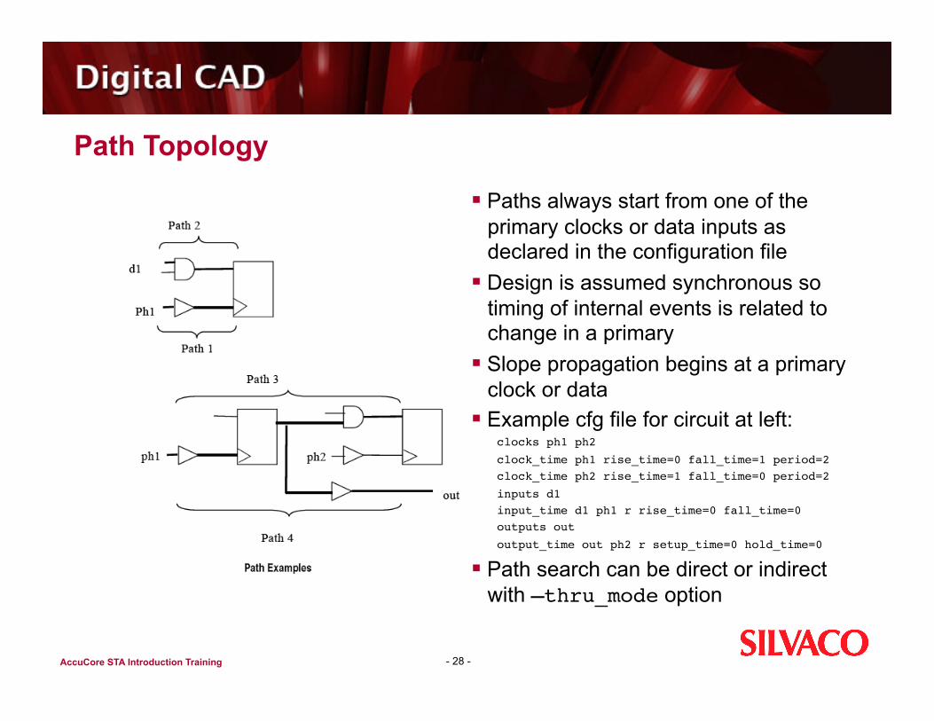
Paths always start from one of the primary clocks or data inputs as declared in the configuration file
Design is assumed synchronous so timing of internal events is related to change in a primary
Slope propagation begins at a primary clock or data
Example cfg file for circuit at left: clocks ph1 ph2
clock_time ph1 rise_time=0 fall_time=1 period=2 clock_time ph2 rise_time=1 fall_time=0 period=2
inputs d1 input_time d1 ph1 r rise_time=0 fall_time=0 outputs out
output_time out ph2 r setup_time=0 hold_time=0
Path search can be direct or indirect with –thru_mode option

AccuCore STA Introduction Training
Critical vs Subcritical vs. Latch-to-Latch Paths
- 29 -
Critical path refers to the longest (setup) or shortest (hold) path for a specific endpoint
Subcritical path is any non-critical path to an endpoint
Latch-to-latch paths refers to a subset of the subcritical paths to endpoints which differ from each other in the preceding latch of the path, or in the primary input if there is no preceding latch Each path of the subset is the worst-case path from its preceding latch or primary input
At left, if the 9.0ps path is the critical path to latch L4, then the latch-to-latch paths to L4 would also include the 8.5ps and 8.8ps paths The complete set of subcritical paths to L4 would also include the 7.0ps path If the cycle time is 8ps, then not only the critical path, but also the 8.5ps and 8.8ps paths must be found and corrected

AccuCore STA Introduction Training
Critical vs. Subcritical vs. Latch-to-Latch Paths
Critical and subcritical path searches are useful for different purposes and, for efficiency, STA uses different algorithms for each of them
Modes for the path search commands: -critical(default mode) -subcritical -latch_to_latch
A critical path search uses the calculation of arrival time windows to prune the search
A -subcritical path search uses the calculation of net slacks to prune the search and is best for exploring timing problems
- 30 -
Critical Path Search using Arrival Time Windows

AccuCore STA Introduction Training
Subcritical and Latch-to-latch Path Search
- 31 -
A subcritical path search is also needed when the path search must be forced to go through specified nets using the -thru_node option of the verify_checks or find_paths commands
The latch-to-latch path mode can be thought of as intermediate between a critical path search and a full subcritical path search.
Subcritical searches tend to find large numbers of paths with the same sending and receiving latches, so it may not give broad coverage of the circuit within reasonable parameters for memory and runtime
The latch-to-latch mode can cover all latch pairs and provide more information than the critical search without the detail of a full subcritical
Another difference between the path modes is in the pruning of subcritical paths at transparent latches
In critical and latch-to-latch mode, any subcritical paths will be pruned out at a transparent latch
In subcritical mode, however, there is no pruning of valid paths at transparent synchronizers

AccuCore STA Introduction Training
Synchronizers and Transparency
- 32 -
Except for the purely combinational case, STA analyzes a circuit as a collection of synchronizers controlled by the clocks defined in the configuration file and connected by blocks of combinational logic
Synchronizers are the gates where signals may have to wait for a clock and can be latches, flip-flops, or domino gates
In addition, tristate-able gates and clocked muxes are treated as synchronizers if they were characterized by AccuCore and if they have an unambiguous clock input
But, if there is no clock input whatsoever, the synchronizers are treated as combinational gates
With the exception of flip-flops, synchronizers are transparent when their clock is active
As a result, the latest output arrival time may be determined either by the latest data input arrival time or by the latest clock enable time as shown in the figure to the left
In the case where data input is later than the clock enable, the terms “timing borrowing” or “flow thru” are sometimes applied

AccuCore STA Introduction Training
Synchronizers and Transparency (cont’d)
- 33 -
For both critical and subcritical paths, path search works through transparent synchronizers
Transparency is checked by comparing the arrival times of the data inputs and the clock enable The process also takes into account the cycle rules between sending and receiving synchronizers
There are two methods for determining the earliest synchronizer output time when the data is later than the clock: In conservative mode, the earliest output time is determined
by the earliest clock enable time only This ensures that any transient effects from initialization are included
In non-conservative mode, the earliest output time is determined by the later of the earliest clock enable and the earliest data input arrival time as shown at left An example of how this might be used is in the analysis of a pipeline circuit in its steady state

AccuCore STA Introduction Training
Path Cycle Rules and Transparency
- 34 -
AccuCore STA needs to know the intended source and destination clock edge times for any pair of synchronizers
Based just on the clocks specifications in the configuration file, the edge times are only defined up to some multiple of the clock period as shown in the Cycle Rules figure at left
As a result, it is necessary to make default assumptions and provide a way to manually override them
The manual overrides are often referred to as multi-cycle path constraints

AccuCore STA Introduction Training
Cycle Rules and path_cycle Command
- 35 -
The default clocking assumptions are changed with the path_cycle command that comes in 3 types: path_cycle -sync <path_src_spec> <path_dest_spec> -cycle <value><R|L> path_cycle -setup <path_src_spec> <path_dest_spec> -cycle <value><R|L> path_cycle -hold <path_src_spec> <path_dest_spec> -cycle <value><R|L>
The -cycle value determines the number of cycles between the clock edges in terms of an interval
The R or L suffix indicates whether the interval includes equality on the right or left end Insertion delays are not included when comparing clock edge times When the source is a primary input/bidir, cycle rules are applied as if the input were
coming from a latch that is enabled by the edge specified with the command input_time in the configuration file

AccuCore STA Introduction Training
Default Synchronizer Rules - Latch-to-Latch Pairs
- 36 -
Since a latch is actually a generic synchronizer, the rule for latch-to-latch pairs applies to any synchronizer, with the exception of domino gates
It says that the nominal time of the enable edge at the destination latch can be the same as the nominal time of the enable edge of the sending latch
It can also be later, but not a whole cycle later This corresponds to the usual ways that latches
are clocked: data is passed between two phases that are less than a cycle apart, and in some cases the phases are the same as shown at left

AccuCore STA Introduction Training
Default Synchronizer Rules - Latch Groups
- 37 -
Path searching through transparent synchronizers becomes more complex when there is sequential looping in the circuit
To address this, the search is sub-divided into latch groups, a set of synchronizer gates connected by sequential feedback paths
This means there is a topological path from the output of any synchronizer in the group to the input of any other synchronizer and that the path passes through combinational blocks and possibly other synchronizers in the group
For example, a latch group might correspond to a state machine constructed using latches and a two-phase clock
Synchronizers that are not in any sequential feedback loop are in a latch group by themselves. This is always the case for flip-flops

AccuCore STA Introduction Training
Latch Group Errors - Latch Loop Violation
When data passes transparently through all latches of a loop, the requirement for synchronous operation is violated
More specifically, the data should have to wait for the clock in at least one latch of any loop, but if the total delay exceeds the sum of the clock phases around the loop, an error occurs
- 38 -
AccuCore STA Introduction Training
Latch Group Errors - Latch Depth Violation and Latch Output Clipping
- 39 -
Latch Depth Violation This error occurs when data passes transparently through more latches than is
allowed. The default value is 10, but this can be overridden with the sta_set_max_depth command
Latch Output Clipping This error results if data arrives at any latch of a group after the clock disable edge Depending on the options used with the path_search command, the errors can be
handled in one of two ways: By disabling the diagnostics with the no_latch_group_diagnostics option, which is
also the default; or By enabling diagnostics with the latch_group_diagnostics option.
If the diagnostics are disabled, a warning is generated and all the data-to-output arcs of all the synchronizers in the group are made non-transparent
Although the analysis of the group is completed, no flow-through paths are included for the synchronizers in the group. This option is more efficient and is very useful for the initial run of a circuit.

AccuCore STA Introduction Training
Combinational Loops
- 40 -
When STA finds a combinational loop, it breaks it by arbitrarily selecting one cell arc along the loop and blocking it
All paths through the blocked arc are then excluded If a default break point would result in missing an important path, the break point can
be moved to a different arc of the loop by blocking the desired arc with the arc_block command. (Loop breaks, however, cannot be changed using the path_block command)
A list of the loop paths and their break points can be obtained using the report_warnings -comb_loops command
Combinational loops often occur in interconnected groups called Strongly Connected Components, SCC’s “pseudo-cells”
These are analogous to the latch groups discussed earlier, but are composed of just combinational gates
For SCC’s it can be helpful to know the whole structure and not just the individual loops that are broken
The report_warnings -comb_sccs command shows all the gates, nets, inputs, and outputs of each SCC found

AccuCore STA Introduction Training
Timing Constraint Verification
- 41 -
A timing constraint is a restriction on the minimum or maximum allowed time between two signal edges
AccuCore STA can verify these types of timing constraints: Output/Bidir assertions Latch/flip-flop checks Domino gate checks Gated clock checks Data-to-data checks Tristate bus checks Latch loop constraints
Timing constraints that are explicitly defined, either in the library or by configuration commands, are verified using the verify_checks command
This will determine the error/margin value as well as the paths for each check. The checks will be sorted according to the error/margin value
AccuCore STA Introduction Training
Timing Constraints and Clock Domains
- 42 -
In STA, the term clock domain refers to a set of clocks that are related in frequency and phase
A clock domain is defined by a clocks command in the configuration file. (In STA, complimentary domains like “main” and “!main” are combined as a single domain.)
STA carries out the analysis of each domain independently AccuCore STA does not consider synchronization or timing checks
between different domains. Data launched by a clock in one domain will not pass through a synchronizer under control of a clock in a different domain, or have timing checks done against data controlled by a clock in a different domain

AccuCore STA Introduction Training
Timing Constraints and Path Cycle Rules
- 43 -
Clock cycle calculations are controlled by the path_cycle command with setup and hold having the following form: path_cycle -setup <path_src_spec> <path_dest_spec> -cycle <value><R|L> path_cycle -hold <path_src_spec> <path_dest_spec> -cycle <value><R|L>
There is a set of default setup/hold rules, which in most cases can be selectively overridden by adding path_cycle commands to the configuration file
The setup and hold rules operate independently of each other and of the synchronization rules discussed earlier
When performing a setup or hold check, STA considers the source and destination synchronizers and looks for a rule that matches the synchronizer pair. If a match is found, the cycle rule value determines the number of clock cycles to assume between source clock enable edge and the destination clock edge specified by the check. If no matching rule is found, the check is omitted
The default rules are all based on a “less than or equal to one cycle” assumption for the time between source and destination clock edges

AccuCore STA Introduction Training
Path Cycle Rules and Clock Uncertainty
- 44 -
If the reference clock edge times in the configuration file have a min-max uncertainty range, then it is the ranges that are shifted by a multiple of the period to satisfy the cycle value of a path_cycle rule
When comparing two ranges, the minimum of one is compared with the maximum of the other; equality means that they overlap
When data is passed between clocks of different frequencies, but in the same clock domain, there can be more than one source-destination clock edge pair to consider when verifying constraints to ensure that the worst case is found
The possible edge pairs are still determined by applying the default or user-specified path_cycle rules, but the clock period used with the rule depends on the rule type

AccuCore STA Introduction Training
Cycle Rule and Multi-frequency Clocks
- 45 -
For setup and sync rules, the default is the destination clock period, but for hold rules, it is the source clock period. The defaults can be overridden with the –use_src_period and –use_dest_period options of the path_cycle command
Figure at left shows examples of the edge pairs that would be checked for rules having four different combinations of edges, cycle values, and selected clock periods

AccuCore STA Introduction Training
Output/Bidir Assertions
- 46 -
Example: clocks main ph1 clock_time ph1 rise_time=0 fall_time=1 period=2 outputs out1 output_time out1 ph1 r setup_time=0.2 hold_time=0.1
Output/bidir assertions are constraints imposed by the external environment. They are defined in the configuration file by the output_time command
When checking output assertions, cycle rules are applied as if the output signal were being latched by the same clock edge as specified with the output_time command
In the example below, the out1 signal is treated as if it were connected to a latch that opens on the falling edge of ph1 and closes on the rising edge

AccuCore STA Introduction Training
Checks for Latches and Flip-flops (1 of 4)
- 47 -
The checks for latches and flip-flops include setup, hold, recovery, removal, skew and minimum pulse width constraints
In Silvaco-formatted libraries the checks are defined by cons_arc statements. For AccuCore-generated libraries, the setup and hold values are determined by characterization
The default cycle rules for the setup and hold checks are: path_cycle -setup-src_local_edge latch_enable \-dest_local_edge latch_disable -cycle 1R
path_cycle -hold -src_local_edge latch_enable \-dest_local_edge latch_disable -cycle 0R
These rules will match any latch or flip-flop source and destination. For a flip-flop, the latch_enable edge type and the latch_disable edge type are both equivalent to the active clock edge of the flop
AccuCore STA Introduction Training
Checks for Latches and Flip-flops (2 of 4)
- 48 -
The first rule says that the nominal time of the clock edge for setup at the destination latch is later than the nominal time of the enable edge of the sending latch Not more than one cycle later The destination edge is assumed to be later, rather than equal, since equality
would imply a normally unintended race condition, and also to handle the usual flop-to-flop timing case
The second rule says that the nominal time of the hold clock edge at the destination latch may be equal to the nominal time of the enable edge of the sending latch, or it may be earlier by less than one cycle Note that the -setup rule also applies to gated clock setup, tristate setup, and
recovery checks The -hold rule also applies to gated clock hold, tristate hold and removal
checks

AccuCore STA Introduction Training
Checks for Latches and Flip-flops (3 of 4)
- 49 -
A
B
C
The example at left shows an example of modifying the path_cycle rules for a two-cycle path between two latches
It assumes that hold checks should be done against the same edges as those for single-cycle paths
Note that the hold rule is the same as the default and so it could be omitted
“B” is the default of the three examples at left

AccuCore STA Introduction Training
Checks for Latches and Flip-flops (4 of 4)
- 50 -
A
B
C
At left is an example of modifying the path_cycle rules for a two-cycle path between two latches
It assumes that hold checks should be done against the same edges as those for single-cycle paths. Note that the hold rule is the same as the default and so it could be omitted
For minimum pulse width checks, the default cycle rule assumes that the signal edges come from consecutive, or the nearest possible source, clock edges
This rule cannot be changed “B” is the default of the three examples at left
AccuCore STA Introduction Training
Gated Clock Checks
- 51 -
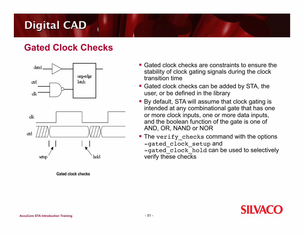
Gated clock checks are constraints to ensure the stability of clock gating signals during the clock transition time
Gated clock checks can be added by STA, the user, or be defined in the library
By default, STA will assume that clock gating is intended at any combinational gate that has one or more clock inputs, one or more data inputs, and the boolean function of the gate is one of AND, OR, NAND or NOR
The verify_checks command with the options -gated_clock_setup and -gated_clock_hold can be used to selectively verify these checks

AccuCore STA Introduction Training
Common Skew Removal
- 52 -
Common skew occurs when the data and clock paths of a timing constraint have shared gates and the shared gates have a delay uncertainty or min/max range
By default, STA will use the max delay values in the long path and the min delays in the short path, resulting in an overly pessimistic value for the margin
The resolve_common_skew option of the verify_checks command will detect common skew and adjust the margins to eliminate it

AccuCore STA Introduction Training
STA Reports
AccuCore STA reports enable designers to: Verify timing check violations for clock controlled elements and primary
outputs Analyze path lengths and signal arrival times Perform net bottleneck analysis based on the net slacks Create a net timing window report that can be used to further tune
timing by introducing a noise (x-coupling) factor to the analysis
- 53 -

AccuCore STA Introduction Training
STA Report report_checks
- 54 -
The report_checks command is based on timing checks performed by the verify_checks command
The report is sorted in order of increasing margin, or slack
Two paths are reported for every timing check The data path from the
clock/primary input to the point where the timing check is performed
The clock path for the clock that is used in the timing check

AccuCore STA Introduction Training
STA Report report_checks (cont’d)
Using report_checks, designers can see how many setup and hold violations there are as well as their severity The first run usually includes just the critical checks using only the worst
timing checks for every timing check instance This report is preferred when checking the overall timing of the circuit
When exploring specific problems, the ability to view multiple timing checks for the same timing check instance may be desired Such a report can be generated with the verify_checkscommand in
a special subcritical mode The path format in the report can be customized using the sta_path_format command
- 55 -

AccuCore STA Introduction Training
STA Report report_paths
The data for report_paths is based on path delays is created using the find_paths command
The report is sorted by the path length and can be customized with the sta_path_format command
The find_paths command has two modes: Critical when only critical paths are reported (default) Subcritical that includes critical and subcritical paths
The critical mode refers to the path with the worst-case length or end time for a given end point and edge (rise or fall)
If the critical path for a given end point and edge is not unique, then a critical-only report will include one path, chosen arbitrarily; and the other paths will be contained in the subcritical report
- 56 -
AccuCore STA Introduction Training
STA Report report_paths (cont’d)
- 57 -
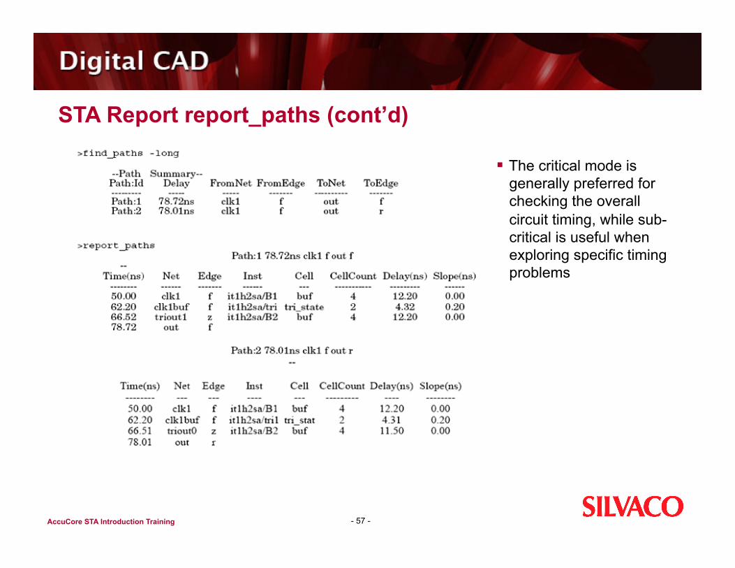
The critical mode is generally preferred for checking the overall circuit timing, while sub-critical is useful when exploring specific timing problems
AccuCore STA Introduction Training
STA Report report_net_slacks
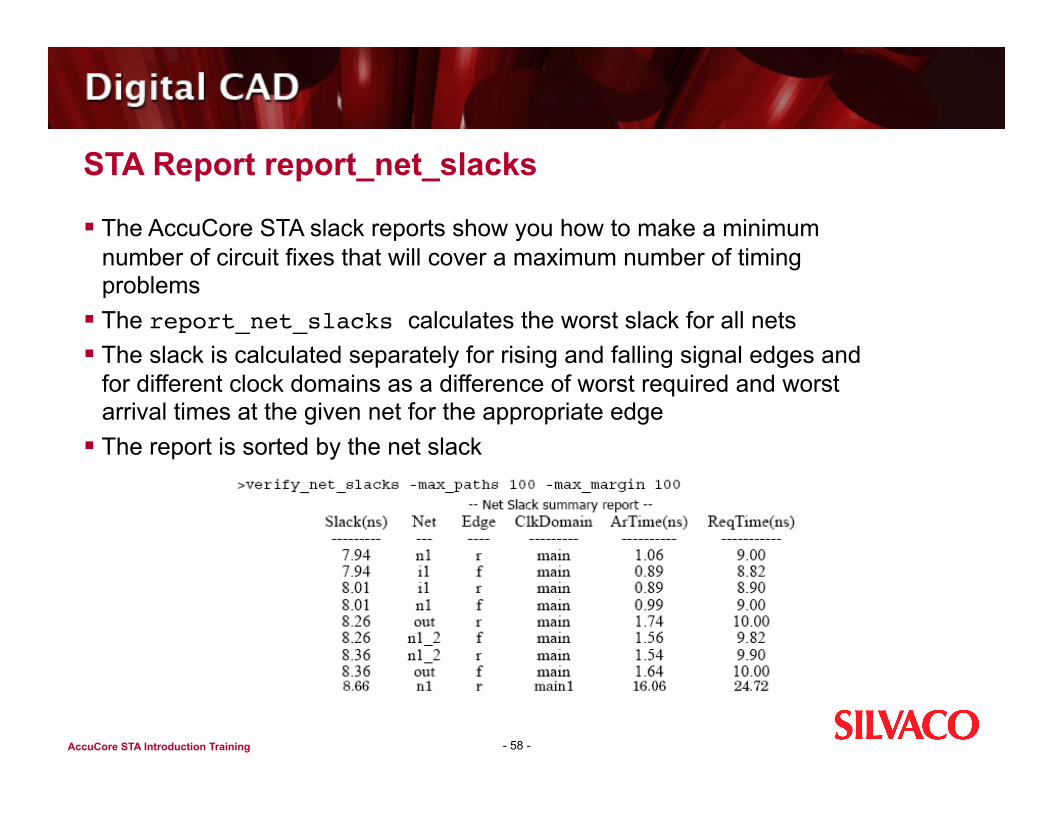
The AccuCore STA slack reports show you how to make a minimum number of circuit fixes that will cover a maximum number of timing problems
The report_net_slacks calculates the worst slack for all nets The slack is calculated separately for rising and falling signal edges and
for different clock domains as a difference of worst required and worst arrival times at the given net for the appropriate edge
The report is sorted by the net slack
- 58 -

AccuCore STA Introduction Training
STA Report report_path_slacks
The report_path_slacks is based on the results of the preceding verify_checks, can be formatted with sta_slack_format must be run in the subcritical mode
This report lists the unique gates/nets that occurred in the paths, with worst-case output net slack, path count, worst-case delay, and worst-case slope
The slack limit and/or count limit can be optionally specified
- 59 -

AccuCore STA Introduction Training
STA Report report_net_timing_window
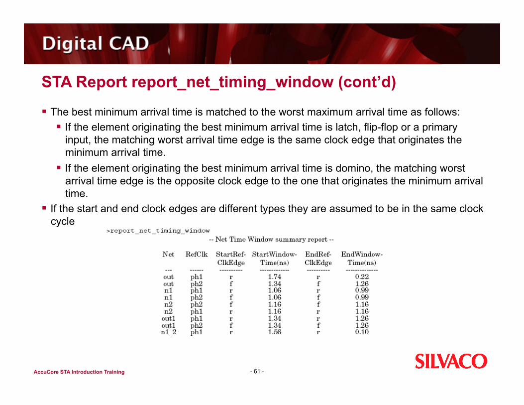
report_net_timing_window aids in identifying net groups that may require additional analysis or that may need to be excluded from further tuning
The timing window is defined by the worst maximum arrival time and the best minimum arrival time relative to the edge of the reference clock for a stable (“0” or “1”) signal
Multiple timing windows are generated for different reference clocks. For the same reference clock multiple timing windows are generated for different starting edges of the reference clock. The starting clock edge is the edge that generates the worst maximum arrival time
60
AccuCore STA Introduction Training
STA Report report_net_timing_window (cont’d)
The best minimum arrival time is matched to the worst maximum arrival time as follows: If the element originating the best minimum arrival time is latch, flip-flop or a primary
input, the matching worst arrival time edge is the same clock edge that originates the minimum arrival time.
If the element originating the best minimum arrival time is domino, the matching worst arrival time edge is the opposite clock edge to the one that originates the minimum arrival time.
If the start and end clock edges are different types they are assumed to be in the same clock cycle
- 61 -

AccuCore STA Introduction Training
SPICE Deck Generation
You can generate SPICE decks of critical paths to verify STA results print_spice_paths should follow the find_paths or verify_checks command
For the verify_checks command the SPICE deck includes both a reference path and a data path. Path numbers are taken from the previous enumerated paths summary or from the detailed path report generated by the preceding find_paths or verify_checks command. For example: print_spice_paths 1-3 file=3.spi
AccuCore characterization generates the .out file with transistor views of simulated partitions. This file should be included in the configuration file of the STA run using the in_txnetlist_name command. For example: in_txnetlist_name design.out
62

AccuCore STA Introduction Training
Running SPICE on Generated Critical Paths and Clock Trees The SPICE deck contains a PWL waveform for each primary input with
slope taken from either the input_time or the clock_time specification in the configuration file
The technology and analysis parameters and output load are included if specified with the output_time command. Retain the MOSFET_TYPE command from the configuration file
Run SPICE and compare the delay of the path with the STA analysis The -add_measure option can be added to the print_spice_paths
command to automatically generate measure statements that assess the delays from path input to path output and from gate inputs to gate outputs
63

AccuCore STA Introduction Training
Running SPICE on Generated Critical Paths and Clock Trees (cont’d) The generated SPICE deck contains useful debugging information
about paths in the SPICE comments such as gate names, cell names, net names, pin names, vectors, etc.
STA can generate the SPICE deck of a complete clock tree with the print_clock_spice_deck command. It marks all gates traversed during clock propagation, collects the termination load and then generates the clock tree SPICE deck
- 64 -

AccuCore STA Introduction Training
STA Timing Models
The sta_create_model command generates an abstract representation of the timing behavior of a block of circuitry
Models also allow for the distribution of designs between different design groups or even between different companies where each design group can: Perform a complete analysis of its share of the circuitry Generate a timing model Pass it to the design integration group that will perform a sign-off timing
verification at the chip level AccuCore STA supports:
Non-transparent black box models Compressed timing models
65

AccuCore STA Introduction Training
Black Box Models
The non-transparent black box model contains only boundary pin information from the block Inputs are modeled using setup and hold times to the first latch, outputs are modeled as
clock to output times, and combinational delays between primary input pins and primary output pins are modeled as pin-to-pin delays
The black box model is environment independent meaning that all abstracted timing arcs are independent of input arrival times and clocking conditions
The output of the black box generation is a single library file consisting of one element which can easily be integrated into the next level of timing analysis
66

AccuCore STA Introduction Training
Compressed Timing Models
AccuCore STA compresses all connected combinational gates of the design to a single gate without changing the sequential parts of the circuit
The output of the compressed model generation flow consists of two files: a new netlist file for the design and a new library file
The library file contains newly generated library cells for combinational parts of the circuit as well as sequential elements from the original library
The model netlist contains newly generated combinational blocks with sequential elements and interface pins
Using these two files, the compressed model can be integrated as a separate module into the full chip netlist for the final analysis
67

AccuCore STA Introduction Training
Block Constraint Generation and Slack Allocation
External timing and load constraints may be created for hierarchical blocks defined by the command sta_generate_constraints
All blocks must be defined as verilog modules in the verilog netlist Timing constraints are created for every primary pin of the hierarchical
block The following constraints are created for different pins:
Inputs/Inouts Worst rise/fall min/max slopes Worst rise/fall max/min arrival times
Outputs/Inouts Worst rise/fall max/min setup times Max/min rise/fall capacitances
68

AccuCore STA Introduction Training
Block Constraint Generation
All constraints will be generated with respect to the edges or reference clocks
If more than one timing constraint is presented for the same module pin with respect to the same reference clock and the same edge, they will be merged and only the worst one will be recorded
Timing constraints for different clock edges of the same reference clock and for different reference clocks will be recorded separately
The output capacitance is the net capacitance for the net without parasitics
If parasitics are present on the net, the constraint cap will be the worst ceff cap for the module output pin
69
AccuCore STA Introduction Training
Block Constraint Generation Options
By default, AccuCore STA generates timing constraints to the block boundary pins
Options to the sta_generate_constraints command enable you to have constraints to the gate pins inside the instance, rather than to the instance boundary pins
This option can be used when several drivers/receivers connected through the distributed RC net on the full chip level and their constraints may be different based on the appropriate RC delay
STA then generates multiple timing constraints to the gate pins which allows better tuning of individual blocks
70

AccuCore STA Introduction Training
Slack Allocation
Both drivers and receivers get 100% of slack by default but the user can specify a slack allocation by using a special option of the sta_generate_constraints command
STA will first allocate the negative slacks based on the user-specified parameter
Each driver/receiver will be assigned the worst slack after analyzing all driver-receiver combinations based on the user-defined criteria
After the negative slack is assigned, STA will allocate positive slacks to only those drivers/receivers that don’t yet have any allocated slack
For positive slacks, the best case is assigned to each driver/receiver
71

AccuCore STA Introduction Training
Interconnect Back Annotation (1 of 5)
STA accepts information about resistive and capacitive interconnects of the gate level netlist in the form of Detailed Standard Parasitics Format (DSPF)
Usually AccuCore characterization accounts for all resistors and capacitors at the block level
DSPF back annotation comes at a top level and represents interconnects between blocks
DSPF can also represent interconnects at a gate level Use the command in_spf_name to specify a DSPF file, or in_hier_spf_name to specify a hierarchical DSPF file
72
AccuCore STA Introduction Training
Interconnect Back Annotation (2 of 5)
The DSPF parasitics file may contain RCs extracted either to the block or gate pins for ASIC blocks, or to the transistor pins for blocks characterized by AccuCore
For the latter case, a special file will be generated containing transistor-to-gate mapping information that is used to match DSPF transistor names with a gate level netlist
- 73 -

AccuCore STA Introduction Training
Interconnect Back Annotation (3 of 5)
STA reads the DSPF file and models every net as a combination of driver-receiver pairs. The figure below shows the driver-receiver model for two inputs and one output
74
The driver is the pi-network and represents the RC circuit as seen by the driving gate
The parameters of the pi-network are found by matching three moments of the RC circuit
The receiver is represented by Elmore delay RC, which is found by matching the first moment of voltage transfer function of the RC circuit

AccuCore STA Introduction Training
Interconnect Back Annotation (4 of 5)
STA calculates delays through interconnect in two stages First, the effective capacitance of the driver is calculated Second, the resulting waveform is used to calculate delay to the receiver pin The total delay is equal to the delay of the gate and the interconnect delay
The effective capacitance is calculated by matching the charge accumulated in the pi-network to the charge accumulated at the effective lumped capacitance The effective capacitance is a function of the input slope at the driving point
which in turn is a function of the effective capacitance and calculated from the slope table representing the cell
The calculation uses an iterative algorithm which requires it to make a consistent input slope at the RC input node with effective capacitance
75

AccuCore STA Introduction Training
Interconnect Back Annotation (5 of 5)
At the second stage, the calculated waveform is applied at the receiver and the delay of interconnect is calculated
The total delay is equal to the delay of the gate and the interconnect delay
- 76 -

AccuCore STA Introduction Training
Parasitic Reduction
The simplest form of interconnect information is a lumped capacitance of the net In this case, net capacitance can be annotated using the command sta_node_cap Note that all occurrences of this command may be collected in one file that can be sourced from the
configuration file STA will account for the net capacitance during delay calculation
An SDF file can be used to account for parasitics delay In this case the file name is specified using the command in_sdf_name STA reads the SDF interconnect delays and includes them in the total delay to the receiver pin of the
next gate
77

AccuCore STA Introduction Training
Input Libraries Merging Options
You can specify default (typical), max, or min libraries in either svc or synthesis formats The libraries are merged internally into the final library that is used for sta analysis The final library may be printed out using sta_print_lib command
The library merge is done using the following rules: First, the master library is chosen If all three types of libraries are presented the default library is chosen as a master
library If no default library is presented, the max library becomes a default library If multiple libraries of the same type are presented they are merged into one library.
The new library will consist of original library cells so that every cell appears in a new library no more than once
If multiple cells with the same name and the same type are presented only once, the arbitrary chosen cell is saved
78

AccuCore STA Introduction Training
Input Libraries Merging Order
The order of the merge if all 3 types of libraries are presented is: max library into the default library min library into the default library The libraries are merged cell by cell The cell from the merged library will be merged into the master library only if
the identical cell exists in the master library. Otherwise, the merged cell is ignored
Two cells are identical if they have the same name, the same number of pins, the same pin names and the same cell and pin attributes
When identical cells are found the timing information is merged pin by pin into the master library
79
AccuCore STA Introduction Training
Corners and STA
Behavior of an electronic circuit is often dependent on various factors in its environment like temperature or local voltage variations In such a case either STA needs to be performed for more than one such set of
conditions, or STA must be prepared to work with a range of possible delays for each component, as opposed to a single value
If the design works at each extreme condition, then under the assumption of monotonic behavior, the design is also qualified for all intermediate points
80

AccuCore STA Introduction Training
Corners and STA (cont’d)
The use of corners in static timing analysis has several limitations It may be overly optimistic, since it assumes perfect tracking - if one
gate is fast, all gates are assumed fast, or if the voltage is low for one gate, it's also low for all others
Corners may also be overly pessimistic, for the worst case corner may seldom occur
In an IC, for example, it may not be rare to have one metal layer at the thin or thick end of its allowed range, but it would be very rare for all 10 layers to be at the same limit, since they are manufactured independently
- 81 -

AccuCore STA Introduction Training
Summary
AccuCore Transistor and Gate Level Full-Chip STA with Automatic Block Characterization provides Static Timing Analysis (STA) of complex designs with mixed design styles
It gives designers the ability to characterize a multi-million transistor design with SmartSpice accuracy and perform block or full-chip static timing analysis
Key Benefits Complete Static Timing Analysis (STA) environment quickly identifies timing
bottlenecks leveraging state-dependent models Automated False Path removal addresses bi-directional transistors Easy setup enables mixing of custom and ASIC blocks in SoC environment Automatically partitions multi-million transistor, flat or hierarchical design with
parasitics into cells for accurate SPICE level characterization Largest collection of calibrated SPICE models for CMOS and SOI, including BSIM3,
BSIM3SOI, BSIM4, PSP, and HiSIM Produces timing models for Liberty .lib format Generates fully-sensitized SPICE deck for critical paths and clock trees
82