Embed Size (px)
Citation preview
116© Crown copyright 2009
AAIB Bulletin: 2/2009 Paramotor EW/C2007/07/02
ACCIDENT
Wing: Paramania Revolution 23
Paramotor unit: Modified H & E Paramotores R120 series
Year of Manufacture: 2005
Date & Time (UTC): 8 July 2007 at 1950 hrs
Location: Middle Barn Farm, Bexhill, East Sussex
Type of Flight: Private
Persons on Board: Crew - 1 Passengers - None
Injuries: Crew - 1 (Fatal) Passengers - N/A
Nature of Damage: Substantial
Commander’s Licence: None required
Commander’s Age: 42 years
Commander’s Flying Experience: 5 years (paramotors)
Information Source: AAIB Field Investigation
Synopsis
The paramotor was being operated by an experienced pilot who was also an instructor. He was seen to initiate what was described as a ‘wingover’ manoeuvre to the right, at about 1,000 ft, but this was seen to develop into a rapid spiral to the left which continued for several turns, with a high rate of descent. The aircraft started to recover at a late stage but the pilot received fatal injuries in the impact with the ground.
There was no defect identified within the wing (canopy and rigging) but structural failures were identified within the paramotor unit, consistent with having occurred in flight and precipitating the spiral descent.
One Safety Recommendation is made to the Civil Aviation Authority concerning self-regulation of this activity.
AAIB Special Bulletin 4/07
In-flight structural failures were identified in the early stages of the investigation and the AAIB published ‘Special Bulletin 4/07’ in August 2007. This was to draw attention to the structural failures, which appeared to have precipitated this accident and also to highlight the lack of regulation concerning the design and construction of paramotors. The Special Bulletin also advised that pilots should refrain from extreme manoeuvres until the structural integrity of these machines be ascertained.
History of the flight
Several instructors, students and other pilots of a paramotor school had spent the day at the site discussing paramotor flying, conducting ground instruction and waiting for conditions to become suitable for flying. At around 1930 hrs, in conditions
117© Crown copyright 2009
AAIB Bulletin: 2/2009 Paramotor EW/C2007/07/02
described as a light west-southwesterly wind and good visibility, three of the more experienced pilots launched.
The pilot involved in the accident was flying a combination of wing and paramotor unit belonging to the school, at which he was an instructor. He had aborted his first three attempts to launch because on each occasion the wing made an uncommanded left turn. On the first launch the wing “dipped” left and the paramotor’s propeller took “a couple of turns around the lines”. Another paramotor pilot freed the lines, the pilot checked them himself and then prepared for the next launch. On the second and third launches the wing turned left again and the assisting pilot noticed that a buckle was caught in the webbing at the base of the lines, fouling the rigging: this was in the ‘B’ line webbing and resulted in the ‘B’ line being shorter than the other flying lines, inducing the uncommanded turn to the left. After the assisting pilot had freed the buckle, the pilot launched without apparent difficulty. He then climbed to approximately 500 ft and appeared to “attempt a wingover”, during which the right side of the wing collapsed over approximately 40% of its span. It re-inflated almost immediately. The pilot then flew normally for several minutes and was seen to conduct some “low skimming”, before climbing to approximately 1,000 ft.
From that altitude he appeared to initiate a wingover to the right but the aircraft almost immediately entered a wingover to the left that developed into a left-hand spiral. The first three turns of this spiral appeared “normal” to the witnesses, in the sense that the speed of rotation was similar to other spiral manoeuvres they had observed. However, the fourth and subsequent turns appeared to develop into a fast rotational manoeuvre in which the vertical axis
of the wing/paramotor unit combination appeared almost horizontal and the axis of rotation appeared to be between the wing and the harness. The aircraft completed five or six such turns until, at approximately 150 ft above the ground, witnesses heard the note of the engine increase, indicating to them that the pilot may have applied full power. The manoeuvre appeared to become less severe, as though the aircraft was beginning to recover to normal flight but, shortly afterwards, it was clear that it had hit the ground, although approximately the last 30 ft of the descent were obscured by low hedges and trees.
The school’s other instructor directed another pilot, who was airborne at the time, to fly over to the site of the impact, some distance from the main gathering. Several witnesses made their way on foot or by car but were hampered by numerous ditches which separated the fields. Others alerted the emergency services, the first of which arrived in vehicles which were also unable to reach the site. One person was able to identify the location using a handheld GPS and directed the air ambulance to within a short distance of the injured pilot.
The pilot was attended at the scene by paramedics then flown to hospital. He remained unconscious throughout and died two days later.
Pilot information
The pilot had flown paragliders since the 1980s. Although no formal record of pilot experience existed (nor was required), family members recalled that he began to fly paramotors five years before the accident. He was a member of the British Microlight Aircraft Association (BMAA) and held a current Foot Launched Microlight Instructor Rating.

118© Crown copyright 2009
AAIB Bulletin: 2/2009 Paramotor EW/C2007/07/02
Colleagues of the pilot described him as having a keen interest in improving the safety of the sport. Members of his family provided documentary evidence of this interest, including drafts of an amended syllabus of training to fly paramotors and notes of discussions he had with several other participants, regarding the foundation of a single organisation to oversee the sport.
Medical and pathological information
The post-mortem revealed the presence of relatively severe coronary artery disease. No acute changes were evident, however, and it is likely that this was an incidental finding. The post-mortem report for HM Coroner stated that the cause of death was multiple injuries.
Meteorological information
No official meteorological observations were available at the accident site. Other paramotor pilots present stated that the surface wind was from the west-southwest at about 4 mph. The wind was stronger aloft, “perhaps 16-18 mph” according to one pilot, but there was little or no thermal activity and no other turbulence. Visibility was “good”, with a mostly clear sky and some cloud to the west with an estimated base at 4,000 ft.
Description of the paramotor A complete paramotor (Figure 1) consists of a wing (canopy) and a system of suspension lines and risers (shrouds), akin to a paraglider, and a lower ‘paramotor unit’ assembly, accommodating the pilot and powerplant. In the accident aircraft the wing and paramotor units came from separate manufacturers and the paramotor unit had been modified.
The fabric wing relies on air pressure at the leading edge to inflate it and produce its aerofoil shape. The upper
and lower surfaces are stitched together at the trailing edge and around the wing tips, but the leading edge has openings and chordwise vertical ribs are attached to the upper and lower surfaces of the wing, dividing it into cells. Holes in the ribs permit the cross-flow of air, so that air pressure inside the wing is equalised. The air pressure inside the wing is dependent on airspeed and the direction of the relative airflow.
In this design, four sets of cords or ‘lines’ are attached to the lower surface of the wing at specific chordwise locations. The lines are made of synthetic fibre and are grouped according to their chordwise location. The ‘A’ lines are attached to the leading edge of the wing, with the ‘B’, ‘C’ and ‘D’ lines being attached at progressively more rearward positions on the wing. Thus, inadvertent shortening of the ‘B’ line webbing on the left, as mentioned earlier, would tend to induce an uncommanded turn in that direction.
The structure of the paramotor unit, the lower assembly, supports the engine and propeller, as well as the rear attachment of the occupant seat support webbing. Hinged arms extend forward from the structure and
Figure 1
Paramotor aircraft - typical
119© Crown copyright 2009
AAIB Bulletin: 2/2009 Paramotor EW/C2007/07/02
during flight support the front attachment webbing of the seat. The arms are suspended at approximately mid-length by a system carrying the lift loads provided by the shrouds of the wing. Limit stops prevent the arms from rotating above a position approximately parallel to the seat base.
A series of holes in the arms enables the attachment point of the lift loads to be altered fore and aft. The largely unchanging load of the engine, propeller and fixed structure is centred behind the rear of the seat attachment, whereas the variable load provided by the occupant is positioned near the mid point of the seat. Variable fore and aft positioning of the lift attachments enables the balance of the system to be adjusted to allow for varying occupant weights.
The lift system is attached generally by shackles, the bolts/pins of which pass through specific holes in the arms chosen to create the desired balance between the suspended mass of the basic unit and that of the occupant. A system of webbing straps provides an alternative load path between the seat support fabric and the lift system, bypassing the arms and their attachments.
The fixed structure of the paramotor unit has slight asymmetry, to balance engine torque, causing the total suspended mass to be offset and leading to a difference in lift forces between the left and right sets of shrouds. This would normally lead to the unit having a curving flight path but the torque reaction of the engine and propeller act in the opposite direction, leading to a balanced condition where the combination has an approximately straight flight path when flying under typical engine power conditions.
Examination of damaged aircraft
General
The paramotor structure, machinery, shrouds and wing
from the accident were subjected to examination some
days after the accident. Examination of the wing and
shrouds revealed no evidence of damage which could
be attributed to any in-flight loading. Sections of the
fabric webbing forming the seat and harness had been
cut; this is understood to have occurred during the
rescue of the pilot.
The normal lift force attachments of the wing to the
hinged arms of the paramotor unit had, however, suffered
a number of failures, leaving the webbing straps as the
sole attachments of the seat base to the shrouds. The
nature of these failures did not indicate that they had
resulted from the ground impact, which predominantly
affected the pilot and was not immediately fatal. In
contrast, very high locally concentrated forces had
failed the metallic lift attachments.
The lift arms attached to this paramotor unit were not
those originally fitted to it by the manufacturer and
these arms had then been further modified. As noted
above, each lift arm was equipped with a row of holes
which enabled the lift load attachment position to be
varied to take account of different occupant weights,
allowing these to be balanced with the fixed weight
of the engine, propeller and mounting structure. In
this example, the right hand side of the paramotor unit
was equipped with a fitting, not forming part of the
original structure, which appeared to be positioned to
alter the offset of the lift load from the centre line
of the box section of the arm. On the left side, the
lift shackle was attached in a more conventional way,
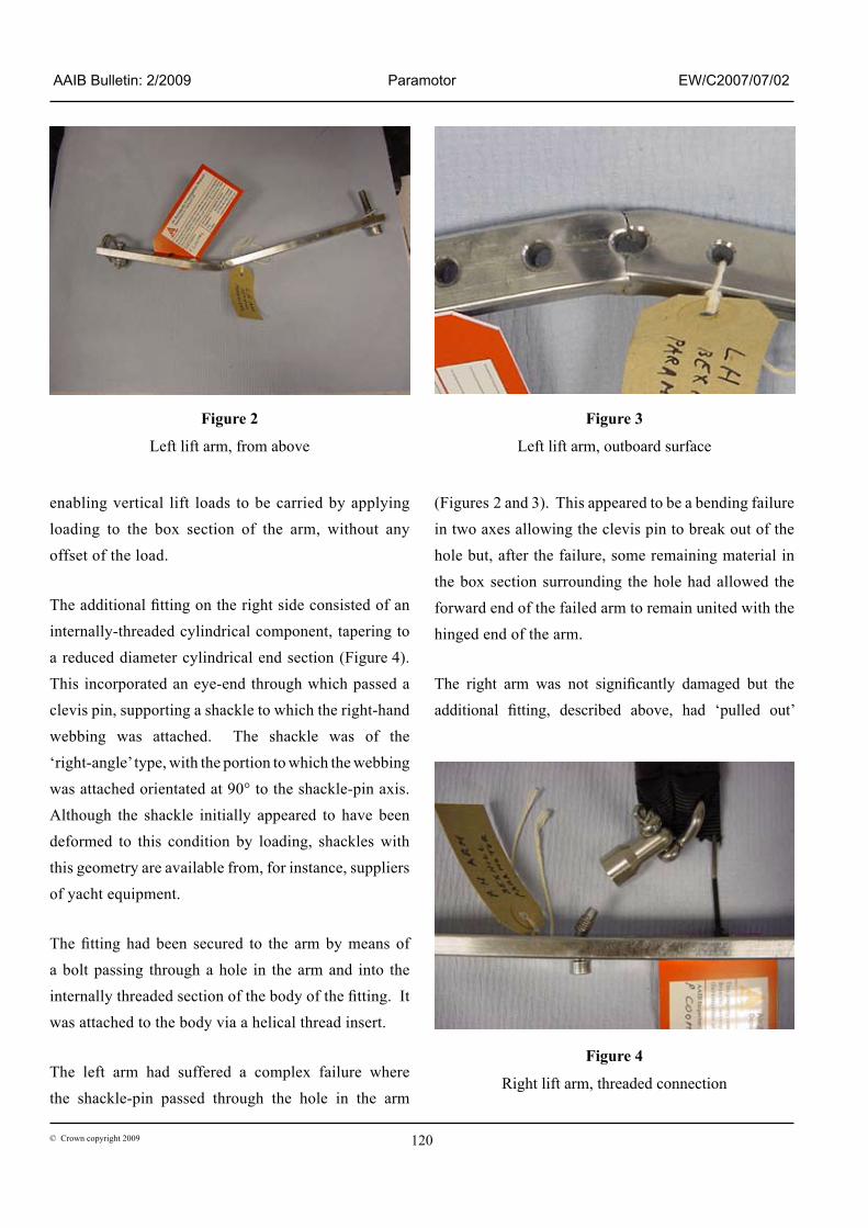
by means of a shackle pin passing through one of the
holes in the corresponding arm (Figures 2 and 3), thus
120© Crown copyright 2009
AAIB Bulletin: 2/2009 Paramotor EW/C2007/07/02
enabling vertical lift loads to be carried by applying loading to the box section of the arm, without any offset of the load.
The additional fitting on the right side consisted of an internally-threaded cylindrical component, tapering to a reduced diameter cylindrical end section (Figure 4). This incorporated an eye-end through which passed a clevis pin, supporting a shackle to which the right-hand webbing was attached. The shackle was of the ‘right-angle’ type, with the portion to which the webbing was attached orientated at 90° to the shackle-pin axis. Although the shackle initially appeared to have been deformed to this condition by loading, shackles with this geometry are available from, for instance, suppliers of yacht equipment.
The fitting had been secured to the arm by means of a bolt passing through a hole in the arm and into the internally threaded section of the body of the fitting. It was attached to the body via a helical thread insert.
The left arm had suffered a complex failure where the shackle-pin passed through the hole in the arm
(Figures 2 and 3). This appeared to be a bending failure in two axes allowing the clevis pin to break out of the hole but, after the failure, some remaining material in the box section surrounding the hole had allowed the forward end of the failed arm to remain united with the hinged end of the arm.
The right arm was not significantly damaged but the additional fitting, described above, had ‘pulled out’
Figure 2
Left lift arm, from above
Figure 3
Left lift arm, outboard surface
Figure 4
Right lift arm, threaded connection
121© Crown copyright 2009
AAIB Bulletin: 2/2009 Paramotor EW/C2007/07/02
(Figure 4) as a result of the threaded insert failing to retain the bolt within the body of that fitting, under the influence of an axial load component. This bolt was also found to be severely bent.
The plywood seat base, on which the pilot would be directly supported, appeared to have suffered partial fracture approximately along its centre line.
Paramotor operations
During the investigation it became apparent that lift arms occasionally deform and fail on paramotors during ‘high load’ manoeuvres, as do the plywood seat bases, but that safe continuation of flight has generally been achieved. In such circumstances, the additional webbing straps, which are normally slack, become the connection between the loaded mid-section of the seat and the load support system, bypassing the relevant arm. In doing so, however, they lose the precise degree of individual occupant balance previously established by the selection of the fore-and-aft attachment position.
The operation of a paraglider (that is, the unpowered type of equipment from which the paramotor family is derived) normally involves suspension of the harness and seat beneath the canopy, in a symmetrical condition. Certain manoeuvres, however, cause geometric asymmetry of this arrangement and ‘normal’ acceleration, resulting from manoeuvres, raise the shroud attachment loads well above those relating to the basic ‘1G’ condition experienced in straight and level flight, or whilst gently altering flight direction.
As previously stated, the paramotor has a further complication in that the torque reaction of the propeller requires a built-in asymmetry of the lower mechanical unit to enable the machine to be easily flown in a straight line during normal powered transit flights.
There is thus a considerable range of load magnitudes
and directions in which forces are applied to the arms.
During a dynamic manoeuvre, the increased loads may
not be evenly distributed between left and right lift
systems and failure of one system may cause sudden
load transfer to the other side with a consequent
‘domino’ failure effect. With the differences in design
and modification between the left and right support
systems in this aircraft, the strengths of the left and
right lift attachments, when loaded in any direction,
would also be different. Since the loads can also
vary in magnitude and direction, especially during
manoeuvring flight, there would be a greater probability
of an initial asymmetric failure leading to load transfer
onto the second lift attachment and then rapidly to a
further failure.
Detailed examination
The structural failures in the paramotor unit were
examined in detail, both at the AAIB and at a specialist
engineering agency. Based on the detail of the failures,
and likely material strengths, a calculation was also
made of the probable failure loads on the two sides.
Examination and sectioning of the right-hand load
attachment fitting revealed that only two threads were
fully engaged and a further four were only partly
engaged. This would significantly reduce the failure
load. In addition, a series of other variable factors would
influence the strength of the attachments:
(1) Equivalent bolt class of the insert (a function
of material, heat treatment and detailed
geometry)
(2) Bolt hardness
(3) Assumed number of thread depths engaged
122© Crown copyright 2009
AAIB Bulletin: 2/2009 Paramotor EW/C2007/07/02
(4) Assumed level of engagement between insert
and connector
(5) Ultimate tensile load of bolt
(6) Estimated remaining load capacity due to
number of threads engaged
(7) Estimated remaining load capability due to
level of engagement of the insert
(8) Magnification of tensile load due to applied
moment
(9) Initial static thread pre-loading resulting from
torque/tension relationship arising from level
of tightness of bolt in fitting.
Calculation showed that, with a direct load (at 90° to
the bolt and fitting, the ‘suspended’ load), the strength
of the right attachment was at its lowest. The failure
load progressively increased to a maximum as the load
angle changed from a direct lateral load on the bolt/
fitting assembly (directly suspended loading) to a pure
axial load on the bolt (entirely lateral load imparted by
canopy to lower unit).
The bending of the bolt during the failure of the fitting
on the right arm indicated a substantial load component
at right angles to the bolt axis. This suggested a failure
load range falling only slightly above the lowest
range of the figures predicted for a direct lateral bolt
load. Circular regions of compressive distortion of
the material of the right arm surrounding the shackle
holes were evident. These indicated that the bolt had
been torque-tightened into the fitting on a number of
occasions, whilst mounted in a number of different
holes. The hole occupied by the bolt on the occasion
of the failure was amongst those with significant
compressive distortion. Calculations showed that
a reduction of load-carrying capacity would have
been created by elevated stresses in the thread form produced by the pre-load forces of the tightened bolt. The small number of threads engaged would also have reduced the attachment strength.
In summary, the conclusion from the calculation of the failure loads was that it was probable that the failure of the bolted attachment (the right side of the paramotor unit) occurred first and load transfer to the shackle/pin attachment (the left side) followed. This sequence was further indicated by the bending directions of the failed left-hand arm, suggesting its failure load occurred after the seat and occupant had rotated about a longitudinal axis following failure of the right-hand attachment.
The likely effect of this sequence is detailed in the Analysis section at the end of this report.
Wing characteristics
The advent of ‘reflex’ wing designs, of which the Paramania Revolution series is an example, has caused a debate within the paraglider and paramotor communities concerning their characteristics and the effects on flight handling. Features of the reflex wing design may cause behavioural differences between this and the more established wing types and such differences may be to the flight path following significant control inputs, but would not manifest themselves in normal flight.
Eyewitness accounts
There were detailed accounts from witnesses with a range of levels of experience. One witness, who knew the accident pilot and was himself an experienced paramotor pilot, commented that “he had self-induced (the initial spiral manoeuvre) at good height but then accelerated. The canopy was juddering which is typical of high speed.” With reference to the broken
123© Crown copyright 2009
AAIB Bulletin: 2/2009 Paramotor EW/C2007/07/02
arms of the paramotor unit, he explained that “a left break would cause a right turn and vice versa.”
One of the students stated that ground training earlier in the day had included a discussion of recovery from spirals, which involved using the reserve parachute if the paramotor failed to recover from a spiral in three turns. The student recalled being told that “a reserve might work even from 80 ft”. The student noted that a reserve parachute is normally an individual purchase and that no reserves were fitted to the club machines. The accident pilot was flying a club machine, to which no reserve parachute was attached during the accident flight.
Another student stated that he understood a “spiral” to involve a high rate of rotation with a high rate of descent, but did not consider this an unusual manoeuvre for an experienced pilot. He had seen several pilots, including the pilot involved in the accident, conduct the manoeuvre on previous flights. Stressing that the accident pilot did not indulge in reckless manoeuvres, one witness commented that a spiral dive was “probably the most radical thing he (the accident pilot) did”.
Regulatory background
The operation of paramotors, in common with all other aircraft in the UK, must comply with the Rules of the Air promulgated in the Air Navigation Order (ANO) in relation to collision avoidance, weather and flight over built up areas. However, they enjoy significant exemptions from registration, certification, maintenance and licensing requirements.
Article 153 of the ANO states:
‘The CAA may exempt from any of the provisions of this Order (other than articles 85, 87, 93, 138, 139, 140, 141 or 154) or any regulations made thereunder, any aircraft or persons or classes of aircraft or persons, either absolutely or subject to such conditions as it thinks fit.’
In the United Kingdom the issue was first addressed in Aeronautical Information Circular (AIC) 109/2000 – ‘Foot launched powered flying machine: (powered paragliders and hang gliders)’, issued by the Civil Aviation Authority on 14 December 2000. It stated that:
‘The arrangements described in this Circular for the operation of such Foot Launched Powered Flying Machines (FLPFMs) have been established with the specific intention of deregulating the activity as much as possible.’
The Circular included a statement exempting FLPFMs from certain provisions of the Air Navigation Order 2000.
On 24 December 2003 the CAA issued the ‘Letter of Consultation – ‘Proposal to Amend Article 129 of the Air Navigation Order 2000 to regularise the operation of foot launched self-propelled hang-gliders (including paragliders) in the United Kingdom’. This document discussed progress on the issue since the issue of AIC 109/2000, noting that since such aircraft were excluded from regulation by the European Aviation Safety Agency (EASA) any regulatory measures remained a matter for national arrangements. It noted that:
124© Crown copyright 2009
AAIB Bulletin: 2/2009 Paramotor EW/C2007/07/02
‘Application of conventional aeroplane requirements would be unlikely to have significant safety benefits.’
In support of this contention, Annex B to the Letter included the following statements:
‘Some flying activities have always been conducted without CAA regulation, for example gliding which can be considered to be self-regulated by the British Gliding Association (BGA). Hang-gliding and paragliding are newer forms of gliding and these operate on a similar basis. In each case these arrangements have been developed and refined over many years, to the satisfaction of the regulator and the relevant airsports association or governing body. The degree of supervision that can be exercised varies from one activity to another. Gliding is of necessity conducted in a club environment, whereas paragliders and paramotors can take off from any suitable site and as a consequence do not easily lend themselves to increased supervision. Nevertheless, structured training syllabi and a culture of responsibility are evident in all these activities. Safety education and information is engendered through a variety of means: by national associations, within the clubs and by individual instructors.’
The Letter concluded that:
‘if the proposed course of action (to amend the Article 129) were to be rejected, the existing legal provisions for aeroplanes would be applicable to foot-launched powered aircraft. This would have some cost implications
for owners, operators and the CAA, yet the registration, certification, maintenance and licensing requirements would be unlikely to have significant safety benefits.’
In the subsequent amendment of the ANO dated January 2007, Article 129 became Article 155.
Definition of self-propelled hang-glider
For regulatory purposes paramotor aircraft fall within the definition of self-propelled hang-gliders and are defined in Article 155 of the ANO as follows:
‘Self-propelled hang-glider’ means an aircraft comprising an aerofoil wing and a mechanical propulsion device which:
(a) is foot launched;
(b) has a stall speed or minimum steady flight speed in the landing configuration not exceeding 35 knots calibrated airspeed;
(c) carries a maximum of two persons;
(d) has a maximum fuel capacity of 10 litres; and
(e) has a maximum unladen weight, including full fuel, of 60 kg for single place aircraft and 70 kg for two place aircraft;’
Article 155 also states that:
‘a reference in this Order to a glider shall include a reference to a self-sustaining glider and a self-propelled hang-glider.’
Consequently, any regulation or exemption applying to gliders also applies to paramotors.
125© Crown copyright 2009
AAIB Bulletin: 2/2009 Paramotor EW/C2007/07/02
Under the terms of Articles 3 and 8 of the ANO
respectively, a paramotor operating on a private flight
which takes place entirely over the United Kingdom is
thus exempt from the requirement to be registered or to
have a certificate of airworthiness. Under the terms of
Article 26, the pilot of a paramotor aircraft operated in
this way is not required to hold a licence.
Organisational information
The school with which the pilot was associated was
affiliated to the BMAA. In the United Kingdom,
the operation of paramotors is supported by both the
BMAA and the British Hang gliding and Paragliding
Association (BHPA). Historically the BMAA has been
associated most closely with small fixed-wing flying
machines and states on its website that:
‘The British Microlight Aircraft Association looks after the interests of microlight owners in the UK. It is an organisation approved by the Civil Aviation Authority (CAA) and has powers delegated to it to control training and airworthiness.’
Similarly, the BHPA states on its website that:
‘The British Hang Gliding & Paragliding Association oversees pilot and instructor training standards, provides technical support, such as airworthiness standards, runs coaching courses for pilots, and supports a network of recreational clubs and registered schools, providing the infrastructure within which UK hang gliding and paragliding thrive.’
Participants in the sport may, but are not required
to, be members of either organisation. Neither
organisation is in fact responsible for the airworthiness
of paramotors and, because no licence is required to operate them, neither organisation has any practical control over training to do so. Both previously offered a syllabus of suggested training but the BMAA ceased to do so in April 2008. Nevertheless, the BMAA and BHPA communicate on matters relating to paramotor operation and the BMAA has stated that it refers to the BHPA questions from participants regarding training. Referring to paramotors as ‘foot launched microlight aircraft, the BMAA is recognised by the Fédération Aéronautique Internationale (the world governing body for air sports and aeronautic world records) as a competent organisation for records and competitions involving these aircraft.
Other applicable legislation
Annex 6 to the Memorandum of Understanding between the Health and Safety Executive (HSE) and the CAA Safety Regulation Group, entitled ‘Recreational Flying and Parachuting’, outlines the interface between the HSE and the CAA in relation to the health and safety of persons involved with, or affected by, recreational flying activities and parachuting. In this context parachuting is taken to include paragliding though not specifically paramotoring. It states, in part:
‘The CAA is responsible, under the terms of the Civil Aviation Act and the Air Navigation Order (ANO) for generally regulating the safety of all aviation activities.
In all cases overall responsibility for the safe regulation of the flying activity remains with the CAA, however the CAA recognises the important role played by the governing bodies of sport. The degree of self-regulation exercised by these sporting bodies is not the same for each activity.’
126© Crown copyright 2009
AAIB Bulletin: 2/2009 Paramotor EW/C2007/07/02
Also,
‘The HSE and the relevant Local Authority (LA) are responsible for enforcing health and safety law at all premises.
Health and Safety Commission (HSC) policy is that duplication of regulatory effort should be avoided. Therefore, HSE inspectors/LA enforcement officers would not normally take enforcement action on those matters which are subject to legislation enforced by the CAA. This includes matters relating to airworthiness of aircraft and the competence, training and conduct of pilots. However, if HSE/LA inspectors have reason for concern they should report this to the relevant authority.’
It concludes that:
‘The CAA will lead on those issues which concern the conduct of any flying activity itself. The HSE/LA will lead on those issues which concern the safety of premises and ground-based activities which involve employment, the self-employed or the provision of non-domestic premises as a place of work.’
Analysis
Engineering aspects
Following this accident unusual damage, not consistent
with ground impact was found in the failures of both
lift arm attachments, and of the plywood seat. This
damage appeared consistent with the behaviour of the
paramotor observed by the witnesses on the ground. The
calculations of the likely failure loads on the two sides,
and the distortion of the hardware, indicated that the
right-hand attachment fitting probably failed first. This
could have precipitated the failure of the left lift arm, at
the hole in that arm supporting the clevis pin carrying
the flight loads.
Effect of structural failure on flight control
Failure of the bolted (right-hand) attachment would
result in an effective increase in the length of the
lines on the right-hand side and an increased tendency
of the paramotor to turn left. If the paramotor was
already in a left-hand spiral, this would increase the
speed of the spiral and might make recovery difficult
using conventional control inputs. If the left-hand
attachment failed subsequently it would restore some
symmetry to the control system and allow the aircraft
to recover more readily, which might accord with
the sequence of manoeuvres and the partial recovery
seen by some witnesses. It is likely, however, that
this change occurred too late for the pilot to effect a
complete recovery before striking the ground.
The lack of recorded information (from photographs,
video, radar or onboard recording) made it impossible
to quantify the speeds and attitudes of this aircraft’s final
manoeuvres. However, it is likely that a combination
of the manoeuvring and the modified structure were the
significant contributing factors in the accident.
Possible ‘fouling’ of the rigging buckle
During the three unsuccessful launches, fouling of the
buckle in the webbing of the left lines resulted in the ‘B’
line being shorter than the other flying lines to the extent
that it induced an uncommanded left turn. The success
of the fourth launch indicates that the buckle was no
longer fouled when the paramotor was launched. The
geometry of the webbing under flight load is such that
the buckle could not then have become fouled except
if this load was removed. The only opportunity for
127© Crown copyright 2009
AAIB Bulletin: 2/2009 Paramotor EW/C2007/07/02
such unloading was presented by the partial collapse of the wing following the manoeuvre characterised by witnesses as an “attempted wingover”. However, since it was the right side of the wing that collapsed it is highly unlikely that the left side would have been unloaded sufficiently for the buckle to become fouled again. There is also no indication from subsequent manoeuvres, during a period of several minutes prior to the commencement of the final spiral, that the pilot was having difficulty controlling the aircraft. It is therefore highly unlikely that the buckle had become fouled at any time during the flight, following the successful fourth launch. Regulation
Many participants have expressed a desire for greater regulation of paramotor activity. In this case the pilot involved was engaged in a flying activity with which he was familiar, in conditions that his colleagues considered suitable. He was widely regarded as experienced, competent and safety conscious and there was documentary evidence that he was a proponent of more rigorous training and oversight of the sport. Given his background, therefore, there is no evidence that greater regulation of the operation of paramotors (as distinct from their airworthiness - design, manufacture and maintenance) would have prevented this accident.
In assessing the effects of exempting self-propelled hang-gliders from certain requirements, the CAA envisaged that:
‘Safety education and information’ would be ‘engendered through a variety of means: by national associations, within the clubs and by individual instructors.’
Although in practice the BMAA and BHPA aim to communicate on related issues, oversight by two organisations risks the division of the sport into two ‘camps’, potentially with opposing views and lacking a common voice. Likewise, there is no single body to which recommendations can be addressed and no single body able to identify, and implement, suitable codes for design, manufacture and maintenance. The gliding movement in the United Kingdom has, in general, developed effectively and safely under the single entity of the British Gliding Association and this is an example of ‘enlightened self-regulation’ in sports aviation.
Under current legislation, the CAA retains ultimate responsibility for the regulation of sport flying activities in the United Kingdom and accordingly the following Safety Recommendation is made:
Safety Recommendation 2008-052
It is recommended that the Civil Aviation Authority should actively develop oversight of the sport of self-propelled hang-gliders, including paramotors, by a single organisation.
41© Crown copyright 2009
AAIB Bulletin: 4/2009 Paramotor EW/C2007/07/02
BULLETIN CORRECTION
AAIB File: EW/C2007/07/02
Wing: Paramania Revolution 23
Paramotor Unit: Modified H & E Paramotores R120 series
Date & Time (UTC): 8 July 2007 at 1950 hrs
Location: Middle Barn Farm, Bexhill, East Sussex
Information Source: AAIB Field Investigation
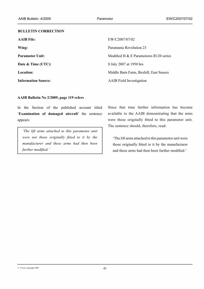
AAIB Bulletin No 2/2009, page 119 refers
In the Section of the published account titled ‘Examination of damaged aircraft’ the sentence appears:
‘The lift arms attached to this paramotor unit were not those originally fitted to it by the manufacturer and these arms had then been further modified.’
Since that time further information has become available to the AAIB demonstrating that the arms were those originally fitted to this paramotor unit. The sentence should, therefore, read:
‘The lift arms attached to this paramotor unit were those originally fitted to it by the manufacturer and these arms had then been further modified.’