Embed Size (px)
Citation preview
AIRCRAFT ACCIDENT REPORT 1/2004
ACCIDENT INVESTIGATION DIVISION
Civil Aviation Department Hong Kong
Report on the accident to Boeing MD11 B-150
at Hong Kong International Airport on 22 August 1999
Hong Kong December 2004
Contents Page
GLOSSARY...............................................................................................................................i
SYNOPSIS................................................................................................................................1
1. FACTUAL INFORMATION ......................................................................................3
1.1. History of the flight..........................................................................................3
1.2. Injuries to persons............................................................................................7
1.3. Damage to aircraft ...........................................................................................7
1.4. Other damage ...................................................................................................8
1.5. Personnel information .....................................................................................9
1.5.1. Flight crew qualifications ........................................................................................9
1.5.2. Flight crew histories ..............................................................................................11
1.5.3. Cabin crew.............................................................................................................12
1.6. Aircraft information ......................................................................................13
1.6.1. Aircraft particulars ................................................................................................13
1.6.2. Maintenance history ..............................................................................................14
1.6.3. Automatic Flight System.......................................................................................15
1.6.4. Windshear Alert and Guidance System .................................................................16
1.6.5. Longitudinal Stability Augmentation System........................................................17
1.6.6. Rain clearance .......................................................................................................18
1.6.7. Radio altitude voice warnings ...............................................................................19
1.7. Meteorological information...........................................................................19
1.7.1. Airport meteorological office ................................................................................19
1.7.2. General weather situation ......................................................................................20
1.7.3. Weather forecasts for Hong Kong International Airport........................................20
1.7.4. Actual weather conditions at Hong Kong International Airport ............................21
1.7.5. Automatic Terminal Information Service ..............................................................23
1.7.6. Runway visual range .............................................................................................23
1.7.7. Surface wind measurement....................................................................................24
1.7.8. Cloud base measurement.......................................................................................25
1.7.9. Rainfall ..................................................................................................................26
1.7.10. Local wind effects at Hong Kong International Airport ........................................26
I
1.7.11. Windshear and Turbulence Warning System .........................................................27
1.7.12. Pilot reports of weather .........................................................................................28
1.8. Aids to navigation ..........................................................................................29 1.8.1. Approach aids........................................................................................................29
1.9. Communications ............................................................................................30
1.10. Aerodrome information.................................................................................30
1.10.1. General ..................................................................................................................30
1.10.2. Lighting aids..........................................................................................................32
1.10.3. Air traffic services .................................................................................................33
1.10.4. Meteorological services.........................................................................................34
1.10.5. Airport fire services...............................................................................................34
1.11. Flight recorders..............................................................................................35
1.11.1. General ..................................................................................................................35
1.11.2. Flight data recorder ...............................................................................................36
1.11.3. Cockpit voice recorder ..........................................................................................37
1.11.4. Quick access recorder............................................................................................38
1.11.5. Data presentation...................................................................................................38
1.11.6. Interpretation of the data .......................................................................................39
1.12. Wreckage and impact information...............................................................41
1.13. Medical and pathological information.........................................................43
1.14. Fire ..................................................................................................................45
1.15. Survival aspects..............................................................................................46
1.15.1. The occurrence ......................................................................................................46
1.15.2. Damage to the cabin ..............................................................................................48
1.15.3. The evacuation ......................................................................................................49
1.15.4. The search and rescue operation............................................................................51
1.16. Tests and analysis ...........................................................................................54 1.16.1. Material and process engineering report................................................................55
1.16.1.1. Testing and examination........................................................................................56
1.16.1.2. Discussion on result of testing and analysis ..........................................................57
1.16.1.3. Conclusion.............................................................................................................59
1.16.2. Sequence and characteristics of structural failure..................................................60
II
1.16.2.1. Analysis techniques ...............................................................................................60
1.16.2.2. Landing conditions and simulation........................................................................62
1.16.2.3. Loads experienced by the structures......................................................................62
1.16.2.4. Structural failure sequence analysis.......................................................................63
1.16.3. Summary of Non-volatile Memory data analysis ..................................................66
1.16.4. Summary of analysis of Electronic Engine Control data.......................................66
1.16.4.1. No. 1 Electronic Engine Control ...........................................................................66
1.16.4.2. No. 2 Electronic Engine Control ...........................................................................68
1.16.4.3. No. 3 Electronic Engine Control ...........................................................................69
1.16.5. Tests of fluid samples ............................................................................................70
1.16.6. Tests of windshield wiper systems ........................................................................71
1.16.7. Test of seat belt at seat 37B ...................................................................................71
1.17. Organisational and management information ............................................71
1.18. Additional information..................................................................................72
1.18.1. Flight crew manuals ..............................................................................................72
1.18.2. En-route and approach charts ................................................................................74
1.18.3. Approaches by other aircraft .................................................................................74
1.18.4. Additional flight data.............................................................................................75
1.18.5. Eyewitness accounts..............................................................................................76
1.18.6. Interviews with the pilots ......................................................................................79
1.18.7. Wind Analysis and Flight Simulations ..................................................................80
1.18.8. MD11 landing accident – Newark International Airport, USA .............................84
2. ANALYSIS..................................................................................................................85
2.1. Scope................................................................................................................85
2.2. Reconstruction of the accident......................................................................85 2.2.1. Descent and intermediate approach.......................................................................85
2.2.2. Final approach .......................................................................................................87
2.2.3. The landing and after landing................................................................................92
2.3. Aircraft serviceability ....................................................................................93
2.4. Weather...........................................................................................................94
2.4.1. Relevance ..............................................................................................................94
2.4.2. Cloud base .............................................................................................................94
2.4.3. Rain and visibility .................................................................................................95
III
2.4.4. Wind conditions.....................................................................................................95
2.5. Hong Kong International Airport ................................................................97 2.5.1. Location of Passenger Terminal Building .............................................................97
2.5.2. Location of Runway 25L touchdown anemometer................................................98
2.6. Flight crew procedures ..................................................................................98 2.6.1. The approach briefing............................................................................................99
2.6.2. Calculation of the final approach speed...............................................................100
2.6.3. Control of power on the approach .......................................................................100
2.7. Cockpit resource management ...................................................................101 2.7.1. Training requirement ...........................................................................................101
2.7.2. CRM aspects of the approach..............................................................................101
2.7.2.1. Delayed approach briefing ..................................................................................101
2.7.2.2. Monitoring by the co-pilot...................................................................................102
2.7.2.3. Use of the autothrottle system .............................................................................104
3. CONCLUSIONS ......................................................................................................106
3.1. Findings.........................................................................................................106
3.2. Causal factors ............................................................................................... 111
4. RECOMMENDATIONS......................................................................................... 112
5. APPENDICES
Appendix 1 - ATIS information reports
Appendix 2 - Survey map: wreckage plot/burn & skid marks
Appendix 3 - Plan of Hong Kong International Airport (HKIA)
Appendix 4 - Record of runway visual ranges
Appendix 5 - Record of wind data
Appendix 6 - Record of cloud base heights
Appendix 7 - Record of rainfall data
IV

Appendix 8 - Record of WTWS alerts
Appendix 9 - ILS approach charts RW 25L/25R
Appendix 10 - Cockpit Voice Recorder transcript
Appendix 11 - Plan of Airfield Ground Lighting at HKIA
Appendix 12 - Plan of rescue services locations at HKIA
Appendix 13 - FDR tabulated/graphical data
Appendix 14 - Calculation of sink rate at touchdown
Appendix 15 - Photographs of wreckage
Appendix 16 - Seat location of seriously injured persons
Appendix 17 - Photographs of damaged fuselage
Appendix 18 - Structural failure sequence analysis
Appendix 19 - Report on windshield wiper tests
Appendix 20 - Summary of approaches
Appendix 21 - Comparative 2000 and 2003 wind data
Appendix 22 - China Airlines MD11 ‘Preparation for Descent Procedure’
Appendix 23 - Comments on the draft final report by the Aviation Safety Council, Taiwan, China
V
GLOSSARY
AAIB Air Accident Investigation Branch (UK)
ACARS Aircraft Communications Addressing and Reporting System Airport Fire ContingentAFC
AGL Airfield Ground Lighting
AIP Aeronautical Information Publication
AND Airplane Nose Down
ANU Airplane Nose Up
APT Automatic Pitch Trim
APV Airport Passenger Vehicle
ASC Aviation Safety Council, Taiwan, China
ATC Air Traffic Control
ATIS Automatic Terminal Information Service
ATS Auto Throttle System
CAM Cockpit Area Microphone
CAWS Central Aural Warning System
CRM Cockpit Resource Management
CVR Cockpit Voice Recorder
°# degree(s)
DFDR Digital Flight Data Recorder
EEC Electronic Engine Control(s)
EEPROM Electrically Erasable Programmable Read Only Memory
EEROM Electrically Erasable Read Only Memory
ETA Estimated Time of Arrival
EPR Engine Pressure Ratio
FCC Flight Control Computer(s)
FCOM Flight Crew Operations Manual
FOM Flight Operations Manual
ft feet
fpm feet per minute
fps feet per second
i
GP Glide Path
GSD Geographic Situation Display(s)
HKIA Hong Kong International Airport
HKO Hong Kong Observatory
hpa hectopascal(s)
hr hour(s)
ICAO International Civil Aviation Organisation
ILS Instrument Landing System
kg kilogram(s)
km kilometre(s)
kN kilonewton
kt knot(s)
L1, L2, L3, L4 Identification of left-side aircraft cabin doors from forward (L1) to rear (L4)
lb pound(s)
L/D Let Down
LMLG Left Main Landing Gear
LSAS Longitudinal Stability Augmentation System
m metre(s)
mm millimeter(s)
m Magnetic
MAC Mean Aerodynamic Chord
METAR Meteorological Actual Report
MLW Maximum Landing Weight
MN meganewton
MSA Minimum Safe Altitude
nm nautical mile(s)
no. number
NVM Non Volatile Memory
NTSB National Transportation Safety Board (USA)
PA Passenger Address
PFD Primary Flight Display
PAPI Precision Approach Path Indicator
ii

PNF Pilot Not Flying
PTB Passenger Terminal Building
QAR Quick Access Recorder
QFE Pressure setting related to touchdown elevation
QNH Pressure setting related to mean sea level
R1, R2, R3, R4 Identification of right-side aircraft cabin doors from forward (R1) to rear (R4)
RA Radio Altitude
RMLG Right Main Landing Gear
RTF Radio telephony
RVR Runway Visual Range
RW Runway
S-B-F-T-T-P Side-Brace-Fitting-To-Trapezoidal –Panel
SCC Stress Corrosion Cracking
SCT Scattered
SIGMET Significant Meteorological warning
SOP Standard Operational Procedure
SPECI Special Meteorological Report
SSCVR Solid State Cockpit Voice Recorder
SSFDR Solid State Flight Data Recorder
STS Severe Tropical Storm
TAF Terminal Area Forecast
Taiwan Taiwan, China
TDZ Touchdown Zone
TDWR Terminal Doppler Weather Radar
TEMPO Temporarily
TRA Throttle Resolver Angle(s)
UTC Universal Time co-ordinated
VHF Very High Frequency
Vref Landing reference speed
WAGS Windshear Alert and Guidance System
WTWS Windshear and Turbulence Warning System
iii
ACCIDENT INVESTIGATION DIVISION
CIVIL AVIATION DEPARTMENT
Aircraft Accident Report 1/2004
Registered Owner : Civil Aeronautics Administration, Taiwan, China
Operator : China Airlines
Aircraft Type : Boeing MD11
Nationality and Registration Mark : B-150
Place of Accident : Hong Kong International Airport
Hong Kong Special Administrative Region
China
Date and time : 22 August 1999 at 1043 hr (1843 hr local time)
All times in this report are UTC and are based on the Hong Kong Air Traffic Control Master
Clock System, except where otherwise specified.
SYNOPSIS
At the time of the accident, Hong Kong International Airport (HKIA) was affected by
weather associated with a tropical cyclone centred approximately 50 kilometres to the north
east. At the airport there was a strong gusting wind from the northwest with heavy rain,
resulting in a wet runway. The Automatic Terminal Information Service (ATIS) included a
warning to pilots to expect significant windshear and severe turbulence on the approach.
1
The aeroplane carried out an Instrument Landing System approach to Runway 25 Left
(RW 25L). After becoming visual with the runway at approximately 700 feet, the
commander then disconnected the autopilot but left the autothrottle system engaged. The
aeroplane continued to track the extended runway centreline, but descended and stabilised
slightly low on the glide-slope until the normal flare height was reached. Although an
attempt was made to flare the aeroplane, this did not arrest the rate of descent and resulted in
an extremely hard impact with the runway in a slightly right wing-down attitude, at an
estimated landing weight of 443 lbs (201 kg) below maximum landing weight. This was
followed by collapse of the right main landing gear, separation of the right wing, an outbreak
of fire and an uncontrollable roll and yaw to the right. The aeroplane ended up in an
inverted, reversed position on a grass area just to the right of the runway.
Rescue vehicles quickly arrived on the scene and suppressed the fire on and in the vicinity of
the aeroplane, allowing rescue of the passengers and crew to progress in very difficult
conditions. Two passengers rescued from the wreckage were certified dead on arrival at
hospital and one passenger died five days later in hospital. A total of 219 persons, including
crewmembers, were admitted to hospital, of whom 50 were seriously injured and 153
sustained minor injuries.
The investigation team identified the cause of the accident as the commander’s inability to
arrest the high rate of descent existing at 50 ft Radio Altitude (RA).
Other probable and possible contributory causes are listed at paragraphs 3.2.2 and 3.2.3 of the
report.
During the course of the investigation, ten safety recommendations were made and are
summarised at paragraph 4 of the report.
2
1. FACTUAL INFORMATION
1.1. History of the flight
China Airline’s flight CI642 was scheduled to operate from Bangkok to Taipei
with an intermediate stop in Hong Kong. The crew had carried out the sector
from Taipei to Bangkok, passing through Hong Kong on the previous day.
On that flight, the crew were aware of the Severe Tropical Storm (STS) ‘Sam’
approaching Hong Kong and the possibility that it would be in the vicinity of
Hong Kong at about the scheduled time of arrival on the following evening.
Weather information provided at the preflight briefing for the return flight
indicated the continuing presence of STS ‘Sam’ with its associated strong
winds and heavy precipitation.
The flight departed from Bangkok on schedule with 300 passengers and 15
crew on board, with an estimated time of arrival (ETA) of 1038 hour (hr) in
Hong Kong. The commander had elected to carry sufficient fuel to permit a
variety of options on arrival – to hold, to make an approach, or to divert. If
an immediate approach was attempted, the aircraft would be close to its
Maximum Landing Weight (MLW) involving, in consequence, a relatively
high speed for the approach and landing.
Throughout the initial stages of the flight and during the cruise, the
commander was aware of the crosswind component to be expected in Hong
Kong and reviewed the values of wind direction and speed which would bring
it within the company’s crosswind limit as applicable to wet runways of 24 kt.
In the latter stage of the cruise, the crew obtained information ‘Whisky’ from
3
the Automatic Terminal Information Service (ATIS) timed at 0940 hr, which
gave a mean surface wind of 320 degrees (º) / 30 knots (kt) maximum 45 kt in
heavy rain, and a warning to expect significant windshear and severe
turbulence on the approach. Although this gave a crosswind component of
26 kt which was in excess of the company’s wet runway limit of 24 kt, the
commander was monitoring the gradual change in wind direction as the storm
progressed, which indicated that the wind direction would possibly shift
sufficiently to reduce the component and thus permit a landing. Hong Kong
Area Radar Control issued a descent clearance to the aircraft at 1014 hr and,
following receipt of ATIS information ‘X-ray’ one minute later, which
included a mean surface wind of 300º at 35 kt, descent was commenced at
1017 hr. Copies of the information sheets used by Air Traffic Control (ATC)
as the basis for ATIS broadcasts ‘Whisky’ and ‘X-ray’ are at Appendix 1.
The approach briefing was initiated by the commander just after commencing
descent. The briefing was given for an Instrument Landing System (ILS)
approach to Runway 25 Right (RW 25R) at HKIA. However, the active
runway, as confirmed by the ATIS was RW 25L. Despite the inclusion in the
ATIS broadcasts of severe turbulence and possible windshear warnings, no
mention was made in the briefing of the commander’s intentions relating to
these weather phenomena nor for any course of action in the event that a
landing could not be made, other than a cursory reference to the published
missed approach procedure.
The descent otherwise continued uneventfully and a routine handover was
made at 1025 hr to Hong Kong Approach Control which instituted radar
vectoring for an ILS approach to what the crew still believed was RW 25R.
4
At 1036 hr, after having been vectored through the RW 25L localiser for
spacing, CI642 was given a heading of 230º to intercept the localiser from the
right and cleared for ILS to RW 25L. The co-pilot acknowledged the
clearance for ILS 25L but queried the RVR (runway visual ranges); these were
passed by the controller, the lowest being 1300 m at the touchdown point.
The commander then quickly re-briefed the minimums and go-around
procedure for RW 25L.
At 1038 hr, about 14 nautical miles (nm) to touchdown, the aircraft was
transferred to Hong Kong Tower and told to continue the approach. At 1041
hr, the crew were given a visibility at touchdown of 1600 metres (m) and
touchdown wind of 320º at 25 kt gusting 33 kt, and cleared to land.
The crew of flight CI642 followed China Airline’s standard procedures during
the approach. Using the autoflight modes of the aircraft, involving full use of
autopilot and autothrottle systems, the flight progressed along the ILS
approach until 700 ft where the crew became visual with the runway and
approach lights of RW 25L. Shortly after this point the commander
disconnected the autopilot and flew the aircraft manually, leaving the
autothrottle system engaged to control the aircraft’s speed.
After autopilot disconnect, the aircraft continued to track the runway
centreline but descended and stabilised slightly low (one dot) on the glideslope.
Despite the gustiness of the wind, the flight continued relatively normally for
the conditions until approximately 250 ft above the ground at which point the
co-pilot noticed a significant decrease in indicated airspeed. Thrust was
applied as the co-pilot called ‘Speed’ and, as a consequence, the indicated
5
airspeed rose to a peak of 175 kt. In response to this speed in excess of the
target approach speed, thrust was reduced and, in the process of accomplishing
this, the aircraft passed the point (50 ft RA) at which the autothrottle system
commands the thrust to idle for landing.
Coincidentally with this, the speed decreased from 175 kt and the rate of
descent began to increase in excess of the previous 750-800 feet per minute
(fpm). Although an attempt was made to flare the aircraft, the high rate of
descent was not arrested, resulting in an extremely hard impact with the
runway in a slightly right wing down attitude (less than 4º), prior to the normal
touchdown zone. The right mainwheels contacted the runway first, followed
by the underside of the right engine cowling. The right main landing gear
collapsed outward, causing damage to the right wing assembly, resulting in its
failure. As the right wing separated, spilled fuel was ignited and the aircraft
rolled inverted and came to rest upside-down alongside the runway facing in
the direction of the approach.
The cockpit crew were disorientated by the inverted position of the aircraft
and found difficulty in locating the engine controls to carry out engine shut
down drills. After extricating themselves, they went through the cockpit
door into the cabin and exited the aircraft through L1 door and began helping
passengers from the aircraft through a hole in the fuselage. Airport fire and
rescue services were quickly on the scene, extinguishing the fuel fire and
evacuating the passengers through the available aircraft exits and ruptures in
the fuselage.
As a result of the accident, two passengers were found dead on arrival at
6
hospital, and six crew members and 45 passengers were seriously injured.
One of the seriously injured passengers died five days later in hospital.
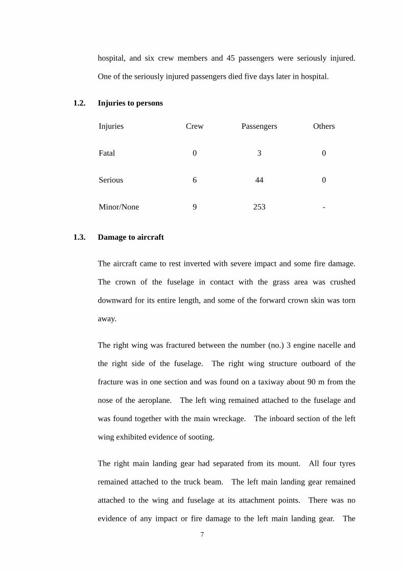
1.2. Injuries to persons
Injuries
Fatal
Crew
0
Passengers
3
Others
0
Serious 6 44 0
Minor/None 9 253
1.3. Damage to aircraft
The aircraft came to rest inverted with severe impact and some fire damage.
The crown of the fuselage in contact with the grass area was crushed
downward for its entire length, and some of the forward crown skin was torn
away.
The right wing was fractured between the number (no.) 3 engine nacelle and
the right side of the fuselage. The right wing structure outboard of the
fracture was in one section and was found on a taxiway about 90 m from the
nose of the aeroplane. The left wing remained attached to the fuselage and
was found together with the main wreckage. The inboard section of the left
wing exhibited evidence of sooting.
The right main landing gear had separated from its mount. All four tyres
remained attached to the truck beam. The left main landing gear remained
attached to the wing and fuselage at its attachment points. There was no
evidence of any impact or fire damage to the left main landing gear. The
7
centre landing gear was fractured at the bottom of the cylinder near the axle.
Its wheel truck with tyres was found on the runway near the wreckage. The
nose landing gear remained attached to the front section of the fuselage with
minimal structural damage, although the right hand nosewheel had separated
from the hub.
All three engines were found at the crash site. No. 1 engine (mounted on the
left wing) remained attached to its pylon structure. No. 2 engine (mounted at
the rear) remained attached to the inlet and engine mounting structure but the
whole assembly was detached from the rear fuselage. No. 3 engine (mounted
on the right wing) remained attached to its pylon structure; however, the whole
assembly was separated from, but lay close to, the wing on the taxiway.
1.4. Other damage
Scratch marks were found on the runway pavement surface starting as a light
skid mark about 250 m to the west of the threshold and 12 m to the north of
the centre line. This mark was almost continuous along the track of the
aircraft, with multiple scratched marks developed on its sides starting from
about 300 m west of the threshold. At around that distance, intermittent
scratch marks were observed close to the centre line. All the scratch marks
ranged from a few centimetres to over one metre wide and from surface
scratches to a maximum depth of 25 millimetres (mm). These marks were
seen deviating to the right from about 450 m west of the threshold extending
to the grass area where the aircraft came to rest.
An area of the runway pavement of about 120 m long and 10 m wide starting
from about 470 m west of the threshold was contaminated by burning fuel.
8
Similar contamination was found on the pavement at taxiway J7 over an area
of about 50 m x 40 m adjacent to the grass area to the east. Burn marks were
also apparent on the grass areas along the path of the aircraft.
A number of inset airfield light fittings including adapter rings, upper cans and
lenses had been damaged by the aircraft. These damaged light fittings
consisted of 10 touchdown zone lights, four runway centre line lights, two stop
bar lights and four exit taxiway centre line lights. In addition, a total of 26
elevated lights including six runway edge lights, 19 taxiway lights and one
runway guard light, plus two movement area guidance signs, were damaged.
However, it is believed that while the aircraft had caused damage to a few of
these lights and to the guidance signs, most of the damage was caused by
vehicles during the rescue operation.
A survey map showing the scratched and burn marks is at Appendix 2.
1.5. Personnel information
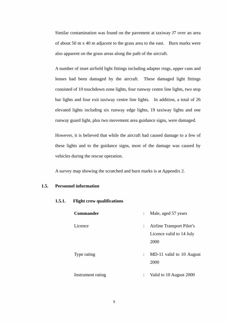
1.5.1. Flight crew qualifications
Commander : Male, aged 57 years
Licence : Airline Transport Pilot’s
Licence valid to 14 July
2000
Type rating : MD-11 valid to 10 August
2000
Instrument rating : Valid to 10 August 2000
9
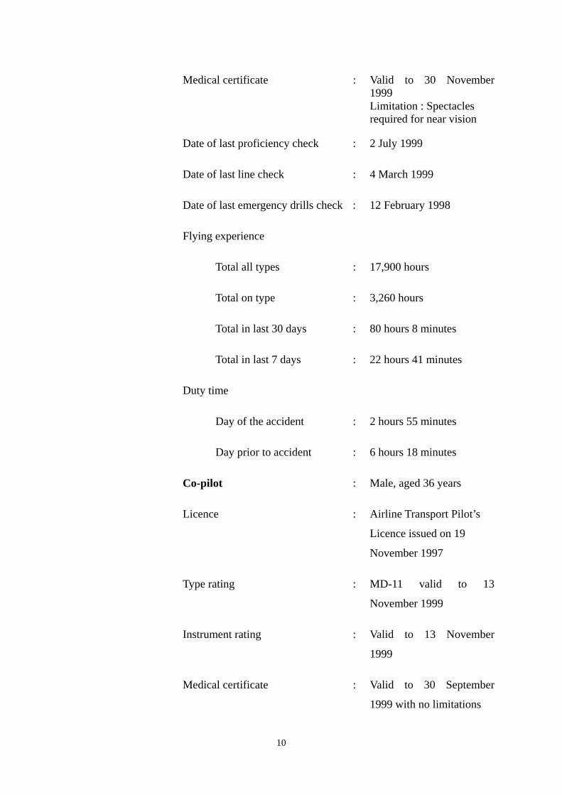
Medical certificate : Valid to 30 November 1999 Limitation : Spectacles required for near vision
Date of last proficiency check : 2 July 1999
Date of last line check : 4 March 1999
Date of last emergency drills check : 12 February 1998
Flying experience
Total all types : 17,900 hours
Total on type : 3,260 hours
Total in last 30 days : 80 hours 8 minutes
Total in last 7 days : 22 hours 41 minutes
Duty time
Day of the accident : 2 hours 55 minutes
Day prior to accident : 6 hours 18 minutes
Co-pilot : Male, aged 36 years
Licence : Airline Transport Pilot’s
Licence issued on 19
November 1997
Type rating : MD-11 valid to 13
November 1999
Instrument rating : Valid to 13 November
1999
Medical certificate : Valid to 30 September
1999 with no limitations
10
Date of last proficiency check : 4 March 1999
Date of last line check : 30 May 1999
Date of last emergency drills check : 7 April 1999
Flying experience
Total all types : 4,630 hours
Total on type : 2,780 hours
Total in last 30 days : 83 hours 49 minutes
Total in last 7 days : 14 hours 11 minutes
Duty time
On day of the accident : 2 hours 55 minutes
On day before the accident : 6 hours 18 minutes
1.5.2. Flight crew histories
The commander joined China Airlines in May 1997 as a MD-11 line
captain following his retirement from a major European national
airline, where he had been an instructor pilot on MD-11 aircraft.
He had a total of 2,300 hours as commander on the MD-11 aircraft.
Following a simulator course and an abridged line training course,
the commander was cleared to fly the MD-11 as a fully qualified
line captain. After two years in this capacity, he underwent a
simulator training course to qualify as a line instructor on the MD-11
and satisfactorily completed this training at the end of May 1999.
11
Throughout his periodic sessions of training and checking, only
minor comments were made on his ability and he was generally
awarded an ‘average’ grading. Earlier in August 1999, the
commander underwent annual training in Cockpit Resource
Management (CRM).
The co-pilot joined China Airlines as an ab initio entrant in May
1989. Following three years of training in the United States, he
graduated as a commercial pilot and commenced a training course
with China Airlines as a co-pilot on B737 aircraft. This was
successfully completed in September 1992. In November 1994, he
commenced a transition course on the MD-11 at the manufacturer’s
facility in Long Beach, California and qualified as a co-pilot in
March 1995. More recently, in November 1998, he qualified as an
in-flight relief captain enabling him to act as relief commander
whilst in the cruise on long haul flights.
The co-pilot’s ability was classed as ‘average’ throughout his career
with China Airlines, with no adverse comments on his training
records. Approximately one month prior to the accident, the
co-pilot also underwent annual CRM training.
Both pilots underwent windshear training in the course of recurrent
simulator training/checking.
1.5.3. Cabin crew
The cabin crew consisted of one purser and twelve flight attendants.
12
All were medically fit and were qualified to carry out their duties in
accordance with the regulatory requirements of Taiwan, China. All
had completed safety and emergency procedure training, and had
been checked by the company, within the 12 months prior to the
accident.
1.6. Aircraft information
1.6.1. Aircraft particulars
Model No. : MD-11, serial no. 48468
Manufacturer : McDonnell Douglas Corporation (now
Boeing Company)
Registered Owner : Civil Aeronautics Administration, Taiwan, China
Registration No. : B-150
Operator : China Airlines
Date of Manufacture : 30 October 1992
Engines : Three Pratt and Whitney PW4460 turbofans
Maximum Landing Weight : 430,000 lbs (195,454 kg)
Estimated Landing Weight : 429,557 lbs (195,253 kg)
Zero Fuel Weight : 388,757 lbs (176,707 kg)
Certificate of Airworthiness : No. 87-09-127, valid from
30 September 1998 – 30 September
1999
Certificate of Registration : No. 81-497, issued on 30 October1992
Total Flying Hours : 30721:32 hours
Total Cycles : 5824
13
1.6.2. Maintenance history
The aircraft was maintained under a China Airlines MD11
Maintenance Programme approved by Civil Aeronautics
Administration, Taiwan, China. The last major checks accomplished
were as follows:
Check Type Date Flying Hours
1A 31 July 1999 30450
7C 28 August 1998 26773
5-year Structural Inspection 18 November 1997 23467
The last weight check was carried out on 12 April 1998. Aircraft
basic weight was 282,400 lbs (128,400 kg); centre of gravity was
32.31% Mean Aerodynamic Chord (MAC).
The aircraft had previously experienced two hard landings. The
first one was on 25 February 1995. Both nose wheels and steering
actuator pressure line were damaged and replaced and the nose
landing gear was removed for detailed inspection. Structural repair
was carried out on wrinkled fuselage skin just aft of the nose landing
gear wheel well. The second hard landing was on 8 August 1997.
The ‘hard landing’ inspection was accomplished and no damage was
found.
Maintenance log pages from November 1997 to August 1999 were
inspected. No significant discrepancy was found.
14
1.6.3. Automatic Flight System
The MD11 is designed to be operated most efficiently through its
automatic flight system. This system is comprised of multiple
autopilots and an autothrottle system which together direct and
control the aircraft in virtually all regimes of flight as required either
by the pilot when utilising basic autoflight modes, or by the Flight
Management System (FMS) when using computer controlled
modes.
In the approach mode, given correct information inserted into the
FMS, the autothrottle controls the aircraft’s airspeed as demanded by
the FMS target. The speed is calculated by the FMS from the
aircraft’s current all-up weight, which provides a basic landing
reference speed (Vref) to which a factor for wind must be added.
This factor makes allowance for the effect of the wind expected on
the approach and is able to account for gusts. In conditions of light
winds, a constant factor of 5 kt is added to the Vref; in stronger
winds, a calculated factor of up to a maximum of 20 kt is added, and
the higher of these two resulting speeds is used for the approach.
Vref + 5 kt is automatically generated by the FMS and this is the
speed on the approach to which the autothrottle will control unless
the speed is modified by the crew. The approach speed may be
modified through the FMS which would normally be done in the
course of the approach briefing, or the current speed target may be
instantly changed by selection and insertion on the mode control
panel in order to cater for wind conditions not foreseen earlier. For
15
CI642’s approach, the crew were using an approach speed of 170 kt,
which had been programmed into the FMS early in the descent.
This is further discussed at paragraph 2.6.2.
The programme for the autothrottle in the final stages of the
approach is designed to ensure that the aircraft crosses the runway
threshold at Vref + 5 kt and touches down at Vref. To accomplish
this, the system receives a radio altitude signal as the aircraft passes
50 ft, at which point the thrust levers are commanded to idle with a
consequent decrease in thrust. This will occur irrespective of the
aircraft’s speed or environmental conditions, unless the autothrottle
is overridden by the handling pilot or the go-around switch is
pressed. Once reverse thrust is selected, autothrottle is disengaged.
1.6.4. Windshear Alert and Guidance System
The MD11 is equipped with a sophisticated Windshear Alert and
Guidance System (WAGS) which provides detection, alerting and
guidance through windshear. Wind and inertia information is
detected by the aircraft’s Central Air Data Computers and by the
Inertial Reference Systems and transmitted to the Flight Control
Computers (FCCs) for windshear detection, warning and guidance.
On approach, the aircraft enters the protection envelope on passing
1500 ft RA and exits on descending below 50 ft RA. Visible
warning of windshear is provided on the pilots’ Primary Flight
Displays (PFDs) and, at the same time, audio warnings are also
generated. Windshear pitch guidance, which is provided to the
16
flight directors and dual autopilots, is only available on the approach
when either the go-around switch is pressed or the thrust is manually
or automatically increased to 95% or more of the go-around thrust
value. Below 50 ft RA, windshear alerting and guidance are not
available and automatic increase in thrust is not provided. In the
course of CI642’s approach, WAGS did not trigger any windshear
warnings.
1.6.5. Longitudinal Stability Augmentation System
The aircraft is equipped with a Longitudinal Stability Augmentation
System (LSAS) which provides pitch attitude hold and limiting pitch
rate damping, automatic pitch trim, speed protection and stall
protection. LSAS is not provided when the autopilot is engaged.
Below 100 ft RA, and transparent to the pilot, LSAS is progressively
removed from the pitch control system.
LSAS holds the aircraft’s current pitch attitude if there is no force on
the control column and the bank angle is less than 30º. If the pilot
manually changes pitch attitude and then removes the control
column force, the aircraft will hold the new pitch attitude.
LSAS holds pitch attitude by deflecting the elevators up to 5º, and
the stabiliser is then automatically adjusted to relieve sustained
elevator deflection and maintain a full 5º of elevator authority.
LSAS also limits pitch attitude to less than 10º of aircraft nose down
(AND) or 30º of aircraft nose up (ANU). Below 15,000 ft, if there
is more than approximately two pounds (lb) (0.9 kilogram) of force
17
on the control column, LSAS is inoperative: once the pilot applies
about four lb (1.8 kg) of control column force, the elevators respond
to the pilot’s commands. Above 20,000 feet, LSAS provides pitch
rate damping when force is applied to the control column. This
damping is gradually reduced to zero between 20,000 and 15,000
feet.
Automatic Pitch Trim (APT) is available when LSAS is in operation.
APT positions the horizontal stabiliser to off-load any steady state
elevator deflections, and varies the trim rate with airspeed for best
performance in all flight conditions. On a manual approach, APT
is inhibited if more than two lb (0.9 kg) force is applied to the
control column, or bank angle exceeds 5º.
1.6.6. Rain clearance
A separate wiper system is installed for the left and right
windshields, each system being independently controlled by a
selector on the forward overhead panel. When the wipers are
selected off, the wiper assembly is designed to move to a parked
position below its windshield and out of the airstream.
Each wiper system contains two protecting circuit breakers, one
rated at five amperes for control and the other rated at 15 amperes
for the motor.
The optional rain repellent system was not fitted to the accident
aircraft.
18
1.6.7. Radio altitude voice warnings
The aircraft is equipped with a Central Aural Warning System
(CAWS) which monitors the aircraft’s two radio altimeters.
Included in the automatic voice callouts, which are triggered by the
system, are callouts of ‘50/40/30/20/10’ ft on the approach. These
callouts, and their cadence, assist pilots in initiating and controlling
the flare immediately prior to touchdown.
1.7. Meteorological information
1.7.1. Airport meteorological office
Forecasts and observations issued by the Hong Kong Observatory’s
(HKO) Airport Meteorological Office (AMO) at Hong Kong
International Airport (HKIA) were disseminated in real time by
video monitor, by point-to-point dedicated circuits and by scheduled
broadcasts, with additional meteorological information available on
request. Routine, special and extra meteorological reports,
trend-type landing forecasts, aerodrome forecasts, SIGMET
information, current RVRs, aerodrome warnings and other relevant
supplementary information were provided to air traffic services units.
Meteorological information transmitted by local data network to
displays at the various ATC positions comprised half-hourly reports,
special reports, aerodrome forecasts, surface wind information and
windshear warnings for HKIA. The locations of the
meteorological sensors for surface wind and RVR measurement at
HKIA are shown on the plan at Appendix 3.
19
1.7.2. General weather situation
The weather on 22 August 1999 was influenced by STS ‘Sam’
which had formed over the Pacific Ocean and was approaching
Hong Kong on a northwesterly track.
A tropical cyclone bulletin issued by the HKO at 0945 hr on
22 August 1999 advised that ‘Sam’ was then centred about
25 kilometres (km) east-northeast of the Observatory (51 km or
27 nm east-northeast of HKIA), and was forecast to move northwest
at about 15 km per hour (8 kt). The ‘Number 8 Northwest Gale or
Storm Signal’ was hoisted, which meant that winds with sustained
speeds of 63 – 117 km per hour (34 - 63 kt) could be expected from
the northwest quarter, with the possibility of gusts exceeding 180 km
per hour (97 kt).
The weather in Hong Kong was overcast with occasional heavy
showers and squalls. The cloud base was generally about 1,000 ft
with visibility falling below 1,000 m at times in rain. Gale force
northwesterly winds prevailed as ‘Sam’ approached the region.
1.7.3. Weather forecasts for Hong Kong International Airport
Before leaving Bangkok, both pilots were aware that weather
conditions at Hong Kong were being influenced by a tropical
cyclone. They were in possession of the relevant significant
weather chart, winds at altitude, terminal approach forecasts and
recent weather reports. The pictorial significant weather chart,
20
valid for 0300 hr on 22 August, showed that an extensive area of
cumulonimbus clouds associated with ‘Sam’ was covering the Hong
Kong area.
The Terminal Area Forecast (TAF) passed to the crew before
departure from Bangkok was issued by HKO at 0400 hr on 22
August and covered the 24 hr period from 0600 hr that day. For
the aircraft’s ETA, the relevant contents can be summarised as
follows:
Wind 320º/30 kt gusting 42 kt; visibility 9,000 m; cloud base - few
1,200 ft, scattered 2,500 ft, broken 10,000 ft.
TEMPO between 0600 - 1200 hr : wind 310º/42 kt gusting 55 kt;
0600 - 0600 hr : visibility 3,000 m; heavy shower or thunderstorm
with moderate rain; cloud - few 800 ft, scattered cumulonimbus
1,400 ft, broken 8,000 ft.
Routine updates to the forecasts were issued by the AMO at 0654 hr
and 0751 hr and were available to the crew via the aircraft’s Aircraft
Communications Addressing and Reporting System (ACARS).
However there were no significant changes from the TAF passed to
the crew before departure.
1.7.4. Actual weather conditions at Hong Kong International Airport
The most recent Meteorological Actual Report (METAR) for HKIA
passed to the crew before departure from Bangkok was issued at
0600 hr on 22 August. The observation included the following
21
relevant details:
Wind 320º/35 kt gusting 47 kt; visibility 6,000 m in light rain
showers; cloud base - few 2,000 ft, scattered 3,000 ft, broken
8,000 ft.
TEMPO: 340º/35 kt gusting 57 kt; 3,000 m; heavy rain shower;
cloud - few cumulonimbus 1,000 ft, scattered 2,000 ft, broken
8,000 ft.
This report was followed by updates at approximately 30-minute
intervals which were available to the crew via ACARS. The
updates did not suggest any significant changes other than
temporary fluctuations in visibility in the heavy showers.
An ‘EXTRA’ observation taken at 1044 hr immediately following
the accident included the following relevant details:
Wind 310º/33 kt maximum 47 kt; visibility 1,400 m; present weather
moderate rain shower; cloud base - few 1,000 ft, scattered 1,600 ft,
broken 8,000 ft; temperature 25º Celsius; dew point 24º Celsius;
QNH 987 hPa; QFE 986 hPa; turbulence warning: moderate to
severe turbulence in vicinity of cumulonimbus on approach and
departure.
TEMPO: wind 330º/38 kt gusting 58 kt; visibility 600 m in heavy
rain shower or thunderstorm with moderate rain; cloud base - few
cumulonimbus 1,000 ft, scattered 2,000 ft, broken 8,000 ft.
22
Note: The turbulence warning had been in effect from 0735 hr until
1732 hr on 22 August 1999 and was included in all ATIS broadcasts
during that period - see paragraph 1.7.5.
1.7.5. Automatic Terminal Information Service
Shortly after commencing descent, the flight crew listened to the
ATIS weather broadcast by VHF radio. A transcript of the
broadcast follows:
‘This is Hong Kong International Airport. Information X-ray at
time one zero zero six. Runway in use two five left, runway two five
right available on request. Expect ILS/DME approach. Runway
surface wet. Braking action reported as good. Surface wind
three zero zero degrees three five knots. Visibility eight hundred
metres in heavy rain. Runway visual range two five left six five
zero metres. Cloud few at one thousand feet, scattered at one
thousand six hundred feet. Temperature two five, dew point two
four. QNH nine eight six hectopascals. Expect significant
windshear and severe turbulence on approach and departure.
Acknowledge information X-ray on frequency one one nine decimal
three five for arrival and one two nine nine for departure.’
1.7.6. Runway visual range
A system for measuring RVR was operating at the time of the
accident, and consisted of three transmissometers for each runway.
Those for RW 07L/25R were situated approximately 80 m north of
23
that runway and those for RW 07R/25L some 90 m south of this
runway, with one transmissometer abeam each touchdown zone and
one abeam the midpoint of each runway. The one-minute mean
touchdown RVR recorded at the time of the accident (1043 hr) was
1900 m for RW 25L and 900 m for RW 25R as shown on the record
for the period 1025-1045 hr at Appendix 4.
1.7.7. Surface wind measurement
Surface wind at HKIA was measured by six sets of anemometers
located abeam the touchdown zones and also abeam the midpoints
of each runway, 10 m above the ground. For RW 25L, the
touchdown zone anemometer was located 330 m west of the
threshold and 120 m north of the runway centre line i.e. between the
runway and the Passenger Terminal Building (PTB), while the other
two anemometers for RW 07R/25L were a similar distance to the
south of the runway; all three anemometers for RW 07L/25R were
located 120 m to the north of that runway (see Appendix 3). The
midpoint wind information from RW 07R/25L site was taken as the
official wind for weather observations, while the information from
all six sites were fed into the windshear and turbulence warning
system for the airport. The surface wind passed to an aircraft with
its landing clearance was taken from the appropriate runway
touchdown zone anemometer.
At each anemometer location, there were two anemometers on the
mast, one designated as operating and the other as stand-by.
24
Consistency checks were performed by the maintenance staff by
comparing the two-minute mean wind readings between the
operating and stand-by anemometers at about 0215 hr on 21 August.
Another consistency check was accomplished at about 0544 hr on
23 August. On both occasions, the differences in readings between
the operating and stand-by anemometers were less than one kt in
speed and 10º in wind direction (directions rounded to nearest 10º)
for all six anemometer locations. The HKO stated that all
anemometers were considered to be operating properly.
Appendix 5-1 shows the two-minute mean wind direction, speed,
and gust values recorded every 10 seconds for the period from 1025
hr to 1045 hr at the six anemometer locations. These values are
utilised, as recommended by the International Civil Aviation
Organisation (ICAO), for reports used for take off and landing and
for wind indicators in air traffic services units.
Appendix 5-2 shows the 10-second mean wind direction and speed
values also recorded every 10 seconds for the same six anemometers
over the same period.
Appendix 5-3 shows the 1-second mean wind direction and speed
values also recorded every 1-second for the same six anemometers.
1.7.8. Cloud base measurement
Cloud base at HKIA was measured by one ceilometer located at the
meteorological enclosure near the ATC tower.
25
Appendix 6 records the one-minute mean cloud base height
(ft above mean sea level) at 10-second intervals from 1041 hr to
1044 hr, and these values indicate a cloud base varying between
781 ft and 2281 ft above aerodrome elevation.
1.7.9. Rainfall
A rain gauge, also located at the meteorological enclosure recorded
5-minute cumulative rainfall data in millimetres.
Appendix 7 shows the 5-minute cumulative values taken at
10-second intervals for the period 1041 hr - 1044 hr and these values
indicate a light to moderate rainfall.
1.7.10. Local wind effects at Hong Kong International Airport
The Aeronautical Information Publication (AIP) Section VHHH AD
2.23 for Hong Kong, dated October 1998 contained the following
text concerning the local effects of northerly winds.
‘Northwesterly Through Northeasterly Winds
When winds are from the north with speeds in excess of 15 kt,
significant low-level windshear and moderate turbulence is expected
to occur along the final approach due to the disturbance by the hills
to the north. Severe turbulence may be expected should the wind
speeds exceed 30 knots. Turbulence level is however less severe
near touchdown than at around 1,000 ft – 2,000 ft. Pilots should
be well prepared for significant crosswind at touchdown.’
26
1.7.11. Windshear and Turbulence Warning System
A Windshear and Turbulence Warning System (WTWS) was
installed at HKIA. Components of the WTWS included
anemometers on and off the airport, wind profilers, and a Terminal
Doppler Weather Radar (TDWR) installed at Tai Lam Chung, about
12 kilometres northeast of HKIA.
The WTWS and TDWR continuously monitor low level windshear
and turbulence induced by terrain and caused by convection within
three nm of the runway thresholds. Alerts from TDWR are
integrated with those from WTWS to provide comprehensive
windshear and turbulence alerts in the vicinity of the airport.
Alerts are given as microburst, windshear, and turbulence, with
associated intensity and location. For windshear and microburst
alerts, the intensity is given as headwind loss or gain in kt, 15 kt
or greater in the case of windshear and 30 kt or greater for
microbursts. For turbulence alerts, the intensity is given as
moderate or severe.
Windshear alerts generated by the TDWR or WTWS are based on
the highest priority, the maximum intensity and the location of the
first encounter with any occurrence for that runway. When both
loss and gain events impact the same area, loss events would have
higher priority over gain events. Event locations for windshear
alerts are given as one, two or three nautical miles on approach or
departure, or on the runway. Event locations for turbulence alerts
27
are given as departure or approach.
WTWS alerts are displayed as alphanumeric messages on dedicated
terminals for use by air traffic controllers. In addition, WTWS
Geographic Situation Displays (GSD) are located in the ATC tower
for use by ATC supervisors and in the AMO for use by HKO
personnel. The GSD shows the horizontal profile of the various
hazardous weather areas as well as the text alert messages.
Appendix 8 shows the WTWS alerts generated between 1005 hr and
1045 hr, which includes the time when CI642 was on its approach to
HKIA. While the system warned of moderate or severe turbulence
throughout the quoted period, the last windshear warning occurred at
1017 hr, some 26 minutes before the accident.
1.7.12. Pilot reports of weather
Although pilots making approaches to HKIA prior to the accident
did confirm some aspects of the prevailing weather conditions, ATC
did not receive any reports of windshear alerts generated by their
aircraft’s onboard windshear warning systems.
The commander of a B747 aircraft which landed at 1036 hr reported
later that, after passing 1,000 ft, the turbulence was moderate in a
steady crosswind of 35 kt. The commander was fully visual by 400
ft, and his visibility was unobscured to touchdown. At 250 ft, he
experienced moderate to severe mechanical turbulence which
decreased at 150 ft, as did the crosswind which he estimated as
28
20-25 kt in the flare.
The commander of a B777 aircraft which landed on RW 25L some
four minutes before CI642 stated later that he became fully visual by
400 ft, although in driving rain. Between 200 and 100 ft, the
aircraft encountered some violent gusts which resulted in speed
fluctuations of 10 – 15 kt, and ‘a large speed reduction’ on entering
the flare, which was successfully countered by a rapid, manual,
application of power.
1.8. Aids to navigation
All relevant navigational aids were serviceable during the period of the
accident flight.
1.8.1. Approach aids
The approach aid in use at the time of the accident was the Category
II instrument landing system (ILS) to RW 25L. The localiser
centre line was aligned to 253°M and the glide-path (GP) was set
at 3°. A distance measuring equipment was co-located with the GP.
Copies of the RW 25L and 25R ILS approach charts are at
Appendix 9.
The ILS was calibrated at quarterly intervals. At the time of the
accident, a calibration aircraft was stationed in Hong Kong for the
periodic calibration. The post accident flight check carried out by
the calibration aircraft confirmed that the ILS was operating
normally.
29
1.9. Communications
The radio callsign for the accident flight was ‘Dynasty 642’. At 1025 hr,
Dynasty 642 established radio communication with Hong Kong Approach
Control on 119.35 MHz, and continued on this frequency until 1038 hr when
the aircraft was passed to Hong Kong Tower on frequency 118.4 MHz.
Continuous speech recording equipment was in operation on both frequencies
and a satisfactory transcript of the communications exchanged between
Dynasty 642 and ATC was obtained and correlated with cockpit voice
recordings (see paragraph 1.11.3). The transcript shows that radiotelephony
(RTF) conversations on both frequencies 119.35 MHz and 118.4 MHz were
conducted in English and proceeded normally. No difficulties in
transmission or reception were evident.
The transcript of relevant RTF messages is included at Appendix 10.
1.10. Aerodrome information
1.10.1. General
HKIA is situated primarily on reclaimed land on the western side of
the Hong Kong Special Administrative Region and is managed by
the Airport Authority Hong Kong. Open seas surround the airport
on three sides. A narrow channel separates the southern side of the
airport and Lantau Island on which high ground rises to a height of
933 m above mean sea level.
The HKIA had two parallel runways, namely runway 07R/25L and
runway 07L/25R, separated by a distance of 1540 m between the
30
centre lines of the two runways. The PTB and the passenger
aprons were located in between the runways on the eastern side of
the airport. Runway 25L was the runway in use at the time of the
accident. It had the following physical characteristics:
Direction : 253°M
Length : 3800 m
Width : 60 m
Shoulders : 7.5 m either side
Surface : Asphalt
Central 54 m grooved (6mm x 6mm) at 32 mm
spacing for a length of 3400 m
Landing Distance Available : 3800 m
Takeoff Run Available : 3800 m
Accelerated Stop Distance Available : 3800 m
Takeoff Distance Available : 4100 m
Runway markings : Runway designation, threshold,
touchdown zone, centre line, fixed
distance markers, side stripe and
runway exits.
A plan of HKIA is at Appendix 3.
31
1.10.2. Lighting aids
The Airfield Ground Lighting (AGL) system at the HKIA was in
compliance with the ICAO Standards and Recommended Practices
for precision approach Category II/III operations. The lighting was
available 24 hours a day and controlled by ATC. The AGL
consisted of both elevated and inset lights. Generally, edge lights
were elevated fixtures with frangible supporting structures and low
enough in height to clear aircraft engine pods and propellers. All
centre line lights were inset fixtures, capable of withstanding aircraft
weight. All lighting had independent intensity variance control to
suit the operational conditions. The AGL comprised the following
lighting systems:
i) Approach lighting consisting of centre line barrettes, side
barrettes, inner crossbar, outer crossbar and sequenced flashing
lights;
ii) Runway lighting consisting of threshold lights, centre line
lights, touchdown zone lights, edge lights and end lights;
iii) Taxiway and taxilane lights consisting of centre line lights,
edge lights, exit taxiway centre line lights, taxiway intersection
lights and hold bars;
iv) Stop bars and runway guard lights at every taxiway entrance to
the runways.
32
v) Precision Approach Path Indicators (PAPIs) installed on both
sides of Runway 25L at a distance of 497 m from the threshold,
with the nominal glide path set at 3° giving a minimum eye
height of 22 m over the threshold.
The daily lighting inspection conducted between 0838 and 0920 on
the day of 22 August 1999 found that all lights were serviceable.
At the time of the accident, the approach lighting and PAPI for RW
25L and the runway lighting were at 100% brightness. Post
accident flight calibration confirmed that the PAPI indication was
coincidental with the ILS glide-path angle.
A plan of the AGL system is at Appendix 11.
In addition, movement area guidance signs were located with
distances from the runway and taxiway pavements, and with heights
in accordance with the ICAO requirements. These signs were
supported by frangible structures.
1.10.3. Air traffic services
The air traffic services at HKIA were provided by the Air Traffic
Management Division of the Civil Aviation Department which was
responsible for the control of air traffic within the Hong Kong Flight
Information Region (FIR) and the additional Area of Responsibility
(AOR).
The Air Traffic Control Centre, which provided Approach Radar
Control, Terminal Radar Control, Area Radar Control and Area
33
Control services, was located at the ATC Complex in the mid-field
area of the airport. This complex also included the ATC Tower,
which provided Air Movement Control, Ground Movement Control,
Zone Control and Clearance Delivery Control services.
1.10.4. Meteorological services
The meteorological services at HKIA were provided by the Airport
Meteorological Office (AMO) of the Hong Kong Observatory. The
AMO was situated in the ATC Complex and performed the
following functions:
a) Aeronautical Meteorological Station
b) Aerodrome Meteorological Office
c) Meteorological Watch Office.
A Meteorological Briefing Area was available in the PTB from
which flight crew members and airline operators could obtain
relevant meteorological information.
1.10.5. Airport fire services
The HKIA had two fire stations and two sea rescue berths. The
main fire station was located south of RW 07R/25L and the sub fire
station was located in between the two runways north of the ATC
complex. The sea rescue berths were located on the north-eastern
and south-western shores of the airport island. The locations of the
fire stations and sea rescue berths are shown in Appendix 12.
34
The fire stations and rescue berths were manned 24 hours a day in
accordance with established procedures. The fire services
personnel were at immediate readiness due to the prevailing adverse
weather conditions. Each fire station had seven rescue and fire
fighting vehicles and one ambulance. The rescue and fire fighting
vehicles consisted of two Rapid Intervention Vehicles (RIV), two
Major Foam Tenders (MFT), two Hose Foam Carriers (HFC) and
one Jackless Snorkel (JS). A total amount of 84,800 litres of water
and 22,080 litres of foam compound meeting the ICAO performance
level B was carried by these vehicles. Additionally, fire hydrants
were installed along the runway shoulders at intervals of 150 m.
The sea rescue berths provided berthing facilities for two command
boats. The command boats were supported by six speed boats.
1.11. Flight recorders
1.11.1. General
All flight recording equipment was recovered from the wreckage by
members of the investigating team shortly after the accident, and
transported to the UK Air Accident Investigation Branch (AAIB) for
replay. The equipment comprised a Digital Flight Data Recorder
(DFDR), Cockpit Voice Recorder (CVR) and a Quick Access
Recorder (QAR). All three units were found to be undamaged on
recovery.
Two members of the US National Transportation Safety Board
35
(NTSB) were present during the replays, and copies of all recovered
information were made available to NTSB and the Air Safety
Council of Taiwan, China.
1.11.2. Flight data recorder
The aircraft was fitted with a Fairchild model F1000 solid-state flight
data recorder (SSFDR). The F1000 stores flight data in a
compressed form in electrically erasable programmable read only
memory (EEPROM).
Almost 350 parameters were recorded on the SSFDR. The
compressed data was downloaded into computer memory via the
SSFDR serial data link, and then decompressed and reduced to
engineering values. In order to ensure all the data pertaining to the
accident flight was recovered, the last bytes of compressed data were
decompressed manually. The SSFDR status information was also
downloaded and confirmed that the equipment ‘BITE’ had detected
no faults.
The recording of longitudinal acceleration was found to be defective,
but all other recorded parameters pertinent to the understanding of
the accident were operational. The lack of longitudinal acceleration
data did make subsequent calculation of the winds experienced by
the aircraft on its final approach more complicated and potentially
less precise than would have been the case with a fully serviceable
SSFDR.
36
1.11.3. Cockpit voice recorder
The CVR installed in the aircraft was a Fairchild Aviation Recorder
Model A200S solid-state cockpit voice recorder (SSCVR).
The SSCVR stores two hours of cockpit audio using EEPROM
recording medium. The recording consisted of four channels of full
bandwidth audio and an additional two hours of reduced bandwidth
audio. During the most recent 30 minutes of recording, both full
bandwidth and reduced bandwidth audio recordings were available.
The channels allocated to the 30-minute recording were:
Channel 1: Passenger Address (PA) and FDR synchronisation signal
Channel 2: Co-pilot (P2) live microphone and Radiotelephony (RTF)
Channel 3: Captain (P1) live microphone and RTF,
Channel 4: Cockpit area microphone (CAM).
The channels allocated to two hour reduced quality recording were:
Channel 1: Reduced quality CAM, channel 4
Channel 2: Reduced quality voice, channel 1, 2 & 3 combined.
The stored information was copied on to audiotapes and the SSCVR
status information was also downloaded. This confirmed that the
equipment ‘BITE’ had detected no faults.
A transcript of the relevant CVR extracts during the descent and final
37
approach produced by the Aviation Safety Council, is included at
Appendix 10.
1.11.4. Quick access recorder
The QAR fitted to the aircraft was a Penny & Giles Type D51434-1.
Documentation obtained from the QAR manufacturer confirmed that
the data was buffered in volatile memory before it was written on
tape. The block structure of the recorded data would result in about
39 seconds of data being lost if the recorder was switched off in a
non-standard way e.g. through interruption of the power supply, as
was the case in the accident flight. As a consequence, data
pertaining to the final 500 feet of the aircraft’s approach was lost due
to interruption of the power supply at impact which caused loss of
the data in the volatile buffer storage.
Data that was available was recovered by the UK AAIB utilising
modified data reduction software which enables recovered data to be
reduced to engineering values.
1.11.5. Data presentation
Time synchronisation of the data obtained from the SSFDR and
SSCVR was achieved by use of a frequency shift keying code,
generated by the flight data acquisition unit, and recorded every four
seconds on the CVR.
Graphs of relevant flight data are at Appendix 13 and show the
38
following parameters:
Appendix 13-1: Tabulated FDR data from 500 ft RA to touchdown.
Appendix 13-2: Graphical FDR data from 700 ft RA to touchdown.
1.11.6. Interpretation of the data
According to the DFDR, the aircraft was following a relatively
stabilised approach in the landing configuration in turbulent and
gusty wind conditions. The airspeed varied about a mean of 165 kt
by approximately +7 and –4 kt and followed the ILS glide slope at a
vertical speed of 750 to 800 feet per minute (fpm). Mean pitch
attitude was about 2.5º airplane nose up (ANU) with some variations
in pitch, possibly in response to wind gusts. The Auto Throttle
System (ATS) remained engaged throughout the approach and the
Throttle Resolver Angles (TRAs) varied generally between 44 and 50 º.
From the point on the approach at which manual control was
established at about 480 ft RA, considerable flight control activity
took place which resulted in vertical accelerations varying between
0.7 and 1.3g.
At 300 ft RA, there was a rapid decrease in indicated air speed from
166 kt to 157 kt, the pitch attitude reduced to less than 2º ANU, the
descent rate increased to approximately 1,100 fpm and the flight
deviated progressively below the ILS glide slope to in excess of one
dot low. The thrust levers then advanced to TRAs between 59 and
62º at a rate of some 3º per second for five seconds, with engine
39
thrust consequently increasing to 1.3 EPR. Indicated airspeed
increased to 175 kt, accompanied by an increase in the angle of
attack to 9º and in pitch to 5º ANU. This stabilised the aircraft at
one dot low on the glide slope and re-established the rate of descent
associated with a normal 3º approach, albeit with the aircraft below
the glideslope.
As the aircraft passed 135 ft, the indicated airspeed approached 175
kt and TRA began to decrease, achieving an angle of approximately
38º as the aircraft passed 60 ft RA. Engine thrust simultaneously
decreased towards flight idle, where it remained until touchdown.
At the same time, the pitch attitude rapidly decreased to 2º ANU and
the angle of attack reduced to a mean of 4º.
Entering the final one hundred feet of the approach, the angle of
attack, as sensed by the two angle of attack (AoA) sensors, fluctuated
with increasing divergence between 3º and 8º, consistent with
significant wind gustiness, these variations oscillating about a one
second period. At the same time, pitch attitudes varied with a
slower periodicity, probably in response to the angle of attack
variations and, possibly, without pilot input.
As the aircraft approached 45 ft RA, elevator angle was quickly
increased to 12º up, then rapidly reversed to 8.5º down, and
maintained at a negative angle of around 5º until approaching 21 ft
RA; during this period, the pitch angle increased from around 3º
ANU to just over 4º then returned to about 3.5º ANU, while the
40
airspeed decreased from 172 kt to 166 kt.
At 21 ft RA, the elevator angle was reversed and was progressively
increased to reach 15.7º up just before touchdown, the pitch angle
simultaneously reached 4.9º ANU and the speed further reduced to
152 kt at touchdown.
During this last 45 ft, the roll angle varied between approximately
wings level and 3º to 4º right wing down, consistent with a
wing-down approach manoeuvre in the prevailing gusting crosswind
conditions, and resulted in the aircraft touching down some 3.5° - 4°
right wing low.
RA data from the FDR indicated an average rate of descent of
approximately 16 feet per second (fps), or 960 fpm, over the last 300
feet of the approach, while The Boeing Company later calculated the
actual rate at the right main landing gear at touchdown as 18 fps, or
1080 fpm.
The methodology used in these calculations has been verified by the
NTSB, and is shown at Appendix 14.
1.12. Wreckage and impact information
After the accident, survey photographs were taken to record the final position
of the main wreckage, the wreckage parts and the skid marks evident on
RW 25L and adjacent landscape areas. Based on the information from these
photographs, a wreckage plot was produced which is shown on the survey
map at Appendix 2.
41
The inverted fuselage wreckage was found on the landscaped area between
Taxiway J6 and J7, with the nose pointing in an approximately easterly
direction. Wreckage parts were also found scattered on the runway and
Taxiways J, J7 and J8. Photographs of the wreckage are included in
Appendix 15.
The broken right wing was found on Taxiway J7 at a location of about 75 m
from the nose of the main wreckage and 30 m from the edge of the runway.
The vertical stabilizer and rudder assembly were found on Taxiway J7 at a
location of approximately 60 m from the nose of the main wreckage and 30 m
from the edge of the runway. Both left-hand and right-hand horizontal
stabilizers and their associate elevators remained attached to the main
fuselage.
The left main landing gear remained attached to the left wing attachment
points. The right main landing gear was detached from the right wing and
rested next to the right-hand horizontal stabilizer of the inverted main
wreckage. The centre landing gear truck bogie had broken off from the shock
strut and was found on the runway. The shock strut remained attached to the
fuselage attachment points. The nose landing gear remained attached to the
fuselage attachment points though its left-hand wheel was detached from the
axle.
No. 1 engine remained attached to the left wing of the main wreckage. No. 2
engine was detached from the main fuselage and was found at approximately
15 m behind the left wing of the main wreckage. No. 3 engine was detached
from the right wing and was found on the edge of Taxiway J7 at a location of
approximately 120 m from the nose of the main wreckage and 30 m from the
42
edge of the runway.
From the wreckage plot, there were three main burn mark areas noted
indicative of post-accident fire. The first one was at the landscape area
between Taxiways J6 and J7 where the main wreckage was located, and took
the shape of a rectangle (90 m x 15 m) together with a triangle (base 45 m x
15 m height). The second one was in the form of a triangle (base 180 m x 45
m height) spreading across Taxiway J7 and the landscape area between
Taxiway J7 and J8. The third one was in the form of a rectangle (120 m x 10 m)
on the runway commencing at a point some 450 m from the runway threshold.
Scrape marks were first noted at a point some 250 m from the runway
threshold. They were initially parallel to the centre line of the runway for a
distance of approximately 380 m where their path started to curve towards the
landscape area between Taxiway J7 and J8, and entered that area at a point
approximately 820 m from the runway threshold. Their path then continued
across Taxiway J7 and into the landscape area between J6 and J7 where the
inverted wreckage finally settled.
1.13. Medical and pathological information
A total of 212 persons, including passengers and crew members, were
admitted to six local hospitals for treatment immediately after the accident.
This figure included two passengers who were certified dead on admission,
and one who died five days later from injuries received in the accident.
Within seven days of the accident, seven more passengers from this flight
reported at various hospitals requesting medical assistance for injuries
apparently sustained in the accident.
43
Urine samples were obtained from the commander and co-pilot about five
hours after the accident, and sent to the Hong Kong Government Laboratory
for testing. Medical examinations of both pilots were conducted some 15
hours after the accident by an aeromedically-qualifed examiner approved by
the Hong Kong Government. There was no evidence of any pre-existing
medical or physical conditions which might have contributed to the accident.
Autopsies of the three fatal passengers were carried out by Medical and Health
Officers from the Forensic Pathology Service of the Department of Health.
The causes of death of the three fatalities were found to be different and were
as follows:
i) The cause of death of the deceased on seat 1K was determined to be
drowning. However, traces of sand and grass were also found in his
trachea, which suggested that he was knocked unconscious at the time
of the accident, but continued to breathe in a mixture of water, sand
and grass.
ii) The passenger who occupied seat 37B had visible bruises to her face
and back. Investigators found that seat 37B seat belt functioned as
required and exhibited no evidence of malfunction. In addition, the
passenger’s autopsy report revealed that there were no marks on her
abdomen associated with seatbelt use, and that she died as a result of
multiple injuries.
iii) The passenger who was on seat 25J died five days later in hospital,
having suffered extensive second degree burns to approximately 55%
of his total body area.
44
The injuries to those admitted to hospital were classified as follows:
♦ 45 burn or scald injuries, of which the majority of the wounds were
located on the limbs, especially on lower limbs;
♦ 45 head injuries;
♦ 31 limb injuries other than burn, scald, contusion, abrasion or laceration;
♦ 22 abrasions or lacerations;
♦ 19 contusions;
♦ 16 neck injuries;
♦ 15 inhalations of smoke or fuel/engine fluid vapor;
♦ 12 back injuries;
♦ 11 chest or rib injuries;
♦ 9 injuries at the waist, hip, pelvic or buttock area; and
♦ 7 shoulder injuries
Some passengers suffered more than one type of injury as classified above.
Some passengers also sustained other minor injuries such as abdominal pain or
soft tissue damage.
A diagram showing the seats occupied by those persons who suffered fatal or
serious injury is at Appendix 16.
1.14. Fire
As the starboard wing of the aircraft began to detach from the fuselage, fire
broke out at the point of failure between the fuselage and the wing, leaving a
trail of fire along the tracks of the aircraft and the starboard wing to their final
45
resting places on the grass area to the right of the runway and on taxiway J7
respectively.
The Duty Air Movement Controller activated the crash alarm to call out the
Airport Fire Contingent (AFC) before the aircraft had come to rest. A total
of 14 AFC appliances arrived at the scene within one minute and immediately
commenced fire fighting at the following locations:
i) detached starboard wing and no. 3 engine on taxiway J7, together with
a trail of spilt fuel pointing to the east covering an area of about 100 m
x 20 m;
ii) rear portion of the aircraft fuselage;
iii) no. 2 engine detached and lying about 20 m to the south of the tail of
the overturned aircraft; and
iv) port wing and no. 1 engine.
It was also apparent that flashes of fire had gone through the R3 door into the
cabin.
The fire on the aircraft fuselage was brought under control within two minutes
and suppressed within five minutes. The fires at the other locations were
completely extinguished within 15 minutes.
1.15. Survival aspects
1.15.1. The occurrence
Prior to landing, the cabin attendants conducted a visual inspection
46
to check that passengers had fastened their seatbelts. After that,
they returned to their respective seats and strapped in for the
landing.
According to statements from surviving passengers, the approach to
land was turbulent and the landing was heavy. Some felt that the
aircraft had tilted to the right and touched down on only the
starboard undercarriage, followed by bumpy movements before the
aircraft overturned. During the sequence, a short flash of fire
entered the cabin from the right wing area near door R3, possibly
prior to or during the overturning of the aircraft. After the aircraft
rolled upside down and yawed through 180 ° to the right, the
forward section of the fuselage impacted the ground first followed
by the aft section and the fuselage then slid backwards due to its
inertia. During the sequence, the flight attendant seated next to
door R1 was thrown outside the aircraft. The crown of the fuselage
was crushed downwards resulting in head injuries to many of the
persons onboard. The aircraft came to rest to the right of RW 25L
at a distance of 1,110 m from the runway threshold - see photograph
of main wreckage in Appendix 17.
The entire cabin was in comparative darkness, except where
illuminated dimly from light sources outside the aircraft, and from
some emergency lights in the aircraft ceiling (which was now
effectively, the cabin floor) which had automatically illuminated on
loss of main aircraft power. Some passengers later commented on
the presence of what they described as these ‘dim lights’.
47
1.15.2. Damage to the cabin
During the crash sequence, the forward fuselage skin was torn and
crushed just aft of the R1 and L1 doors, corresponding to business
class seats 1A and 1K through 5A and 5K, along the left and right
sides of the cabin. A passenger seated on 1K was rendered
unconscious and subsequently drowned. A picture of seats 1J and
1K taken after the accident is included in Appendix 17. The cabin
wall on the right fuselage next to seats 1K through 5K was deformed
inboard, with seats 1J and 1K separated from their respective seat
tracks. The cabin floor and lower seat structures surrounding seat
25J, located in front of the R3 exit, were scorched and burned. The
flight attendant seat adjacent to door R3 was also burned and heavily
sooted, and the flight attendant at this seat suffered serious burn
injuries. The lavatory forward wall immediately aft of door R3
was burned and blistered. A large section of the left side of the
fuselage was torn forward and aft of door L2 and parallel with the
window belt, corresponding to seats in rows 4A/4B through
17A/17B.
The back of the seats 25J and 25K were burned, and passenger
windows were severely crazed between seats 20K and 32K. This
was consistent with the statements of survivors that the short flash of
fire entered the cabin via the R3 door. A picture of the burned and
blistered lavatory wall is included in Appendix 17. Many
passengers seated on the starboard side in the mid-section of the
cabin suffered burns varying from minor to severe to the leg, back
48
and/or right side of the body. The passenger on seat 25J sustained
extensive second degree burns and died five days later in hospital.
Doors L1, R2, R3, L4 and R4 were jammed either closed or partially
open due to damage sustained to the crown of the fuselage, while
doors R1, L2 and L3 were separated from the aircraft.
During the crash sequence, rainwater lying on the grass surface of
the airport to the right of RW25L entered the cabin through the gaps
and cracks which opened in the fuselage just aft of the R1 and L1
doors. The cabin also became quickly contaminated with fuel and
hydraulic fluid.
1.15.3. The evacuation
Immediately after the aircraft came to a halt, the flight attendants
began to look for torches to assist them in the evacuation. The task
of locating torches was complicated by the aircraft being inverted
and the fact that the aircraft ceiling (now floor) was cluttered with
debris.
Statements given by surviving passengers confirmed that their
seatbelts had been fastened for the landing. However, some
passengers stated that they unbuckled their seatbelts immediately
after the first touchdown; one passenger confirmed that she had
unfastened her seatbelt just before the aircraft rolled inverted, and
was then thrown around inside the cabin until the aircraft came to a
halt. Some passengers dropped down and were injured on
49
releasing their seatbelts, while others had difficulty in releasing their
seatbelts and had to be assisted by companions or by rescue crew.
The restraining effect of the seatbelts, and of unfastening them and
falling to the ceiling from the inverted position, appears to be
consistent with the reports of persons suffering from injuries to the
neck, shoulder, back, chest, ribs, waist, hip, pelvis or buttocks.
Sensing the emergency, many of the passengers commenced
evacuation on their own initiative. The cabin crew also started to
direct passengers to the available exits. After completion of the
emergency checklist, the flight crew also assisted in directing
passengers to the nearest exit. Some passengers also elected to stay
inside the cabin to assist in the evacuation of other passengers.
During the initial stage of the evacuation, several passengers were
struck by objects falling from the cabin floor above, possibly
damaged cabin furnishings or passengers’ personal belongings.
They were also subjected to dripping water and a liquid which smelt
like fuel. The clothing of most passengers became soaked. Some
passengers commented that their evacuation was slowed by the
debris inside the cabin, and also by other passengers who were
trying to recover their hand luggage. The presence of debris and of
belongings of other passengers lying on the aircraft ceiling therefore
became a distinct hindrance to the evacuation. As a result, many
persons sustained lower limb injuries during the evacuation.
Pictures of the business and economy class sections after the
accident are included in Appendix 17.
50
In the early stage of the evacuation, some passengers and crew
members attempted to open doors L1, R2, R3, L4 and R4 without
success, and they subsequently followed other passengers to leave
the aircraft via the available exits. These exits were doors L3 and
R1, and the cracked hole that was torn open by the impact in the
fuselage aft of door L2. Pictures of these exit areas are shown in
Appendix 17.
Once outside, the passengers began to spread out in all directions to
distance themselves from the aircraft, which was still burning
around the area where the right wing had detached. Considerable
efforts were required by the rescue crew to re-direct evacuees away
from the aircraft, and to avoid some other fires which were still
burning on the ground.
1.15.4. The search and rescue operation
The fire-fighting and rescue operations were conducted concurrently
by the rescue services upon their arrival at the scene shortly after
1045 hr. Initially two ambulances from the AFC arrived together
with the fire appliances. More rescue services in terms of firemen,
ambulance crews and medical practitioners were called from areas
outside the airport to assist in the search and rescue operations.
The ambulance crew who arrived at the scene shortly after 1045 hr
set up a first casualty clearing station at taxiway J6 to provide
immediate medical treatment to the casualties.
The first fireman who entered the cabin via door R1 at around
51
1048 hr described later that there was smoke and a smell of jet fuel
but no fire inside the cabin. More firemen wearing breathing
apparatus began to enter the cabin to release passengers who were
still strapped onto their seats in the inverted position, or to assist
persons who were not able to evacuate by themselves. The search
and rescue operation inside the aircraft was constrained by the
narrow space and the absence of a clear gangway. The entire cabin
was in comparative darkness and flooded with water to about 0.6 m
high.
Some passengers were assisted to evacuate the aircraft by firemen
through the fuselage skin that was torn open by the impact in the
area aft of door L2, and through doors L3 and R1 respectively. The
AFC had attempted to further open the cracked hole but they had
limited success and only managed to extend the opening by two to
three inches. The AFC also made considerable efforts to force
open other closed doors, and subsequently managed to fully open
door R2 and partially open door R4 after the various fires were
extinguished. After the passengers were assisted from the aircraft,
they were led to safety at temporary collection points on RW
07R/25L, taxiway J and taxiway J6.
Firemen found a passenger who had occupied seat 37B lying on the
cabin ceiling near seat 37B. She was certified dead on arrival at
hospital.
52
By 1053 hr, some 200 passengers had been rescued and led to safety
at the temporary collection points. The remaining passengers left
the aircraft in the early stages of the evacuation either unassisted or
assisted by other passengers or crew members. At 1111 hr, the first
ambulance conveying five casualties departed for hospital. A
second casualty clearing station was established at taxiway J7 at
1145 hr. A temporary mortuary was also established at the scene
utilising an ambulance. A triage point was set up at the South
Airport Passenger Vehicle (APV) lounge on the ground floor of the
PTB. Eleven transport vehicles from an airport service provider
were sent to the scene for transporting crew members and
passengers to the South APV lounge. As all occupants in the
aircraft had not been accounted for, the search for occupants
continued in comparative darkness. At 1300 hr, the AFC reported
that a seat unit, which was later confirmed to be seat 1J and K, was
found to be separated from the seat tracks and was lying on the
ground immediately beside door R1 partly immersed in water. A
passenger, who was certified dead on arrival at hospital, was
restrained in seat 1K. The fireman who found the deceased stated
that water had accumulated up to knee level in and around the
fuselage in that area.
At 1350 hr, all known casualties had been treated and/or conveyed
to various hospitals for further treatment. Search operations
continued until 1935 hr when confirmation was received from the
Police that all persons had been accounted for.
53
Some passengers who suffered burn injuries developed skin
infections later and required further treatment in hospital. Medical
teams from the Department of Health and from the airport private
clinic were called to assist in the treatment of casualties at the scene
and at the South APV lounge.
1.16. Tests and analysis
The objective of this section of the report is to provide a brief account of the
tests and analysis completed on these wreckage parts by the Engineering
Group. There is no intention to describe any details of a particular test,
which are covered in the original reports.
After the accident, the Engineering Group had some mechanical parts and
on-board computers removed from the wreckage and sent to Boeing, Long
Beach for metallurgical and non-volatile memory (NVM) data analysis. The
three Electronic Engine Controls (EEC) were sent to Pratt & Whitney for data
analysis, and components of the windshield wiper system were tested for
serviceability in Hong Kong. The seat belt from seat 37B was forwarded to
NTSB for confirmation of its functioning capability.
The Engineering Group met twice in September and November 1999 at
Boeing, Long Beach to discuss the scope of the metallurgical analysis required
and witnessed some of the testing. The Engineering Group also agreed with
Boeing to send parts to the original equipment manufacturer (OEM) for
analysis if required.
54
Subsequent to the analysis, Boeing has produced three reports to consolidate
the findings. These reports are:
a) Material and Process Engineering Report on China Airlines MD11
Fuselage Number 518 Accident at Hong Kong International Airport,
Hong Kong, China.
b) Sequence and Characteristics of the Structural Failure of the China
Airlines MD11 Fuselage Number 518 – August 22, 1999 Accident at
Hong Kong International Airport, Hong Kong, China.
c) NVM Summary – China Airlines Accident, Flight 642 MD11
Fulselage 518, August 22, 1999.
Also, Pratt & Whitney has produced evaluation reports of the three EECs
examined. The title of these reports is ‘Evaluation of Data Recovered from
China Airlines MD11 Flight 642 Electronic Engine Control – Engine #1/2/3’.
1.16.1. Material and process engineering report
The report details the metallurgical examination and analysis of
selected structural parts sent to Boeing, Long Beach. Each part
was analysed for failure modes, failure origin areas and
abnormalities. Hardness and conductivity measurements, chemical
analysis, tensile, and dimensional inspection were performed only
on selected parts.
The report subdivides the various parts into eight major categories:
i) Wing rear spar and support structure
55
ii) Wing front spar and support structure (inboard of no. 3
pylon)
iii) Trapezoidal panel and support structure
iv) Right main landing gear (RMLG) and support structure
v) Left main landing gear (LMLG) and support structure
vi) Centre landing gear and support structure
vii) No. 3 engine pylon and support structure
viii) Passenger’s seat 1 J/K and seat track (1st class section)
1.16.1.1. Testing and examination
With the concurrence and participation of the
Engineering Group, all the wreckage parts sent to
Boeing, Long Beach underwent the following tests and
examinations, where appropriate, to determine the
failure characteristics.
a) Visual Inspection
b) Dimensional Inspection
c) Macroscopic Examination
d) Hardness Test
e) Tensile Test
56
f) Conductivity Test
g) Scanning Electron Microscope Analysis
h) Chemical Analysis
1.16.1.2. Discussion on result of testing and analysis
All the primary fractures of the failed assemblies and
components that were analyzed, evaluated, and/or tested
by Boeing, Long Beach occurred by ductile overload.
There was no evidence found that associated the
initiation of any of the primary fractures to brittle
failure mechanism (stress corrosion cracking (SCC),
fatigue, etc.). Also, there was no evidence to associate
the cause of the fractures to other than the accident at
HKIA.
The overall fracture characteristics and directions of
deformation of the RMLG forward trunnion bolt
indicated that the forward portion of the failed trunnion
bolt had been pushed forward and had rotated. The
inboard position of the lubrication (zirk) fitting
appeared to indicate that the aft sleeve and most likely
the aft forward RMLG fractured trunnion bolt had not
rotated. These observations appeared to suggest that
the forward RMLG trunnion bolt had moved upward
relative to the wing attachment support (support
57
fitting/attachment fitting). The oblique region found
on the fracture surface of the RMLG trunnion bolt,
which extended outside of the zero-margin groove,
appeared to be the terminal portion of the fracture.
Evidence on the aft axle of the RMLG showed that it
was deformed (bent) upwards at the inboard and
outboard ends, due to the accident sequence.
Some of the components analysed exhibited secondary
intergranular and quasi-cleavage fractures, indicating
brittle failure mechanisms. These secondary brittle
failures are the result of SCC, which is supported by the
following facts:
a) They appeared to be associated with mechanical
damaged regions or adjacent to primary fracture
surfaces which are sources of high sustained
residual stresses.
b) The parts were exposed to harsh and hostile
environments (moisture, fire, extinguisher
chemicals, water, etc.) after the accident, which
could also include the transportation to Long
Beach by ocean shipment.
58
The analysis of the seat tracks and seat did indicate that
the seat separated from its tracks when the seat tracks
failed by ductile overload.
There are differences in the acid number and particle
count found between the results of the analysis
performed on the fluid from RMLG and LMLG and that
of the requirements of Douglas Process Manual
Specification DPM 6176 and DPM 6177 and/or
Military Specification MIL-H-5056. Such differences
cannot be explained completely. However, the
possibility of contamination, testing techniques, the
accident sequence, post-accident conditions (including
the transport of the landing gears to Long Beach) can be
considered to be contributing factors in the lack of
correspondence.
1.16.1.3. Conclusion
The primary fractures of all the failed parts occurred by
ductile overload failure.
All the parts/components and assemblies analysed,
evaluated and/or tested met the applicable engineering
drawings and specifications.
All secondary cracks were due to stress corrosion
cracking.
59
There was no evidence to associate the cause of the
fractures to other than the accident at HKIA.
1.16.2. Sequence and characteristics of structural failure
After the accident, Boeing conducted a structural failure sequence
analysis on the accident and produced a report, which details the
analysis techniques applied to determine the structural failure
sequence of the accident, based on the information obtained from
site investigation and metallurgical analysis of wreckage parts.
The following is a summary of the report, which is reproduced in
full at Appendix 18.
1.16.2.1. Analysis techniques
When the wreckage parts were examined and analysed
at Boeing, Long Beach, it was found that the structural
failure observed from this accident aircraft was very
similar to that from the FedEx MD-11 involved in an
accident at Newark, New Jersey on 31 July 1997,
particularly that of the right wing rear spar.
During the investigation of the FedEx MD-11 accident,
a significant amount of analysis was conducted to
simulate the accident and estimate structural loads on
the RMLG, the RMLG-to-wing attachment fitting, the
right wing rear spar, and the right landing gear
side-brace-fitting-to-trapezoidal-panel (S-B-F-T-T-P)
60
joint. This analysis was conducted using an in-house
aircraft dynamic landing program (B7DC), a
commercially available finite element program (MSC
NASTRAN), and a commercially available nonlinear
kinematics code (ADAMS).
Based on knowledge and experience gained from the
FedEx accident, a simplified analysis technique was
developed for studying the effects of very high sink rate
landings on aircraft structure. The crash landing
analysis performed for this accident utilized MSC
NASTRAN. A transient nonlinear solution was run
using a detailed finite element model of the MD-11
inboard wing and center fuselage, combined with a
coarser idealization of the remaining structure. The
main landing gear was idealized by using a nonlinear
spring and damper element (BUSH1D), which allowed
the gear characteristics to be input in table form. The
results from this model were compared and correlated
with certification analysis (for cases within the design
limits of the aircraft) and with the FedEx ADAMS
analysis and were shown to be satisfactory.
The most significant difference in the structural loads
applied to the aircraft during the FedEx and the China
Airlines accidents lay in the drag loads applied to the
right main landing gear, which in the FedEx case was
61
minimal. To cater for this difference, an adjustment to
the simplified MSC NASTRAN was made. Spin-up
and spring-back loads were estimated using B7DC and
the time history was manually input into the MSC
NASTRAN solution. The peak load from the B7DC
time history was phased to correspond with the peak
right main landing gear vertical load.
1.16.2.2. Landing conditions and simulation
The attitude of the accident aircraft, along with the
velocity and acceleration components, were estimated
from the data obtained from the flight data recorder.
The sink rate was estimated to be in the vicinity of
18 fps. The roll attitude was estimated to be
approximately 3.5-4º right-wing-down and the pitch
attitude was estimated to be 4.5º nose-up.
1.16.2.3. Loads experienced by the structures
By applying the simulation techniques mentioned, the
peak loads experienced by the RMLG strut and the
RMLG forward trunnion bolt at the time of the accident
was estimated to be 1.4 million lb (6.23 MN) and
1.2 million lb (5.34 MN) respectively. Also, the peak
rear spar shear flow was estimated to be 35,000 lb per
inch (6,129 kN per m). The rear spar shear flow is
well in excess of what is required to fail the rear spar
62
shear web and the forward trunnion bolt load is roughly
that required to fail it.
1.16.2.4. Structural failure sequence analysis
The result of the analysis confirms that loads high
enough to fail the RMLG forward trunnion bolt and the
rear spar web were feasible, and that the failure
sequence described in the following subparagraphs is
reasonable.
♦ Due to the combination of a high sink rate and a
right-wing-low rolled attitude, the right main
landing gear shock strut bottomed and the vertical
load on the right main gear ‘spiked’.
♦ The forward trunnion bolt on the right main landing
gear sheared upwards as a result of a very high
vertical gear load combined with a large
‘springback’ moment.
♦ The forward trunnion of the right main landing gear
was driven upwards and contacted the
MLG-to-wing attachment fitting, damaging the
fitting.
♦ The rear spar web and caps inboard of the
MLG-to-wing attachment fitting of the right wing
fractured.
63
♦ The inboard upper wing panel of the right wing
began to collapse from back to front.
♦ The outboard (right) wing twisted significantly
nose down, which caused the MLG-to-wing
attachment fitting to move up and the main landing
gear tires to move aft and outboard.
♦ The track attached to the inboard flap on the right
wing was pried off the rollers that support it at the
fuselage side-of-body.
♦ The inboard flap on the right wing twisted off its
outboard hinge support fitting and separated from
the aircraft.
♦ Excessive movement of the right main landing gear
and its wing attachment fitting imparted large
‘prying’ loads on the S-B-F-T-T-P joint.
♦ The right main landing gear fixed brace failed near
the S-B-F-T-T-P joint.
♦ With the side brace failed, large sideloads were
introduced to the S-B-F-T-T-P joint by the folding
side brace.
♦ The S-B-F-T-T-P joint failed; first the inboard
attachment bolt fractured, then an outboard section
64
of the outboard trapezoidal panel ‘split off’
releasing the outboard attachment bolt and its barrel
nut.
♦ The right main landing gear strut, now released
from the fuselage (trap panel), pivoted outboard;
the trunnion arms contacted the MLG-to-wing
attachment fitting. The resulting ‘short couple’
(prying) loads completed the separation of the
landing gear from the attachment fitting.
♦ The right nacelle contacted the runway (at about the
same time as the inboard flap was separating and
the S-B-F-T-T-P joint was failing) and the right
wing engine/pylon assembly was twisted off. The
pylon-wing separation appears to have been
dominated by side loads applied to the nacelle
rather than vertical loads.
♦ The aircraft began to roll clockwise having lost the
integrity of the right wing, yet still carrying enough
speed to generate meaningful lift on the left hand
wing.
♦ Failures beyond this point were consequential, are
not considered particularly relevant, and were not
studied in detail.
65
1.16.3. Summary of Non-volatile Memory data analysis
The following avionics components were sent to Boeing for
Non-volatile Memory (NVM) data retrieval and analysis:
a) Brake Temperature Monitor / Tyre Pressure Indicator
b) Electrical Power Control Unit
c) Three Generator Control Units
d) Auxiliary Data Acquisition System / Data Management Unit
e) Flight Control Computers
On conclusion of the analysis, none of the NVM in the components
that were sent to Boeing provided any information or evidence that
may have contributed to the cause of the accident.
1.16.4. Summary of analysis of Electronic Engine Control data
This summary provides a description of the Electrically Erasable
Read Only Memory (EEROM) data that was recovered from each
channel of the three Electronic Engine Control (EEC) units of the
CI642 wreckage.
1.16.4.1. No. 1 Electronic Engine Control
The EEROM data from the EEC mounted on no. 1
Engine were successfully recovered. A review of these
data has revealed that channel A contained diagnostic
messages that spanned the last 573 flight hours and 293
66
flight cycles while channel B contained messages that
spanned the last 400 flight hours and 293 flight cycles.
Neither channel A nor channel B had recorded any
messages for 28 flights prior to the terminal flight. On
the terminal flight, 11 messages involving channel A
and 10 messages involving channel B were recorded.
On channel A, three of the messages are consistent with
interruptions on circuits between engine and aircraft.
Five of the messages provide troubleshooting guidance,
but do not identify a specific system or component. The
remaining three messages identify anomalies with the
engine inlet pressure/temperature sense system and the
execution of the compressor Stall Recovery Logic.
These recorded messages are consistent with either the
dynamics of the aircraft during the accident or the
observed engine damage from the accident.
On channel B, three of the messages are consistent with
interruptions on circuits between engine and aircraft.
Four of the messages provide troubleshooting guidance,
but do not point to a specific system or component. The
remaining three messages identify anomalies with the
engine inlet pressure/temperature sense system and the
execution of the compressor Stall Recovery Logic.
These recorded messages are consistent with either the
67
dynamics of the aircraft during the accident or the
observed engine damage from the accident.
1.16.4.2. No. 2 Electronic Engine Control
The EEROM data from the EEC mounted on no. 2
Engine were successfully recovered. A review of these
data has revealed that both channel A and channel B
contained diagnostic messages that spanned the last 315
flight hours and 232 flight cycles. Neither channel A nor
channel B had recorded any messages for 137 flights
prior to the terminal flight. On the terminal flight, 16
messages involving channel A were recorded and 11
messages involving channel B were recorded.
On channel A, three of the messages are consistent with
interruptions on circuits between engine and aircraft.
Nine of the messages provide troubleshooting guidance,
but do not identify a specific system or component. The
remaining four messages identify anomalies with the
engine inlet pressure/temperature sense system and the
execution of the compressor Stall Recovery Logic.
These recorded messages are consistent with either the
dynamics of the aircraft during the accident or the
observed engine damage from the accident.
On channel B, three of the messages are consistent with
interruptions on circuits between engine and aircraft.
68
Five of the messages provide troubleshooting guidance,
but do not point to a specific system or component. The
remaining three messages identify anomalies with the
engine inlet pressure/temperature sense system and the
execution of the compressor Stall Recovery Logic.
These recorded messages are consistent with either the
dynamics of the aircraft during the accident or the
observed engine damage from the accident.
1.16.4.3. No. 3 Electronic Engine Control
The EEROM data from the EEC mounted on no. 3
Engine were successfully recovered. A review of these
data has revealed that both channel A and channel B
contained diagnostic messages that spanned the last 203
flight hours and 150 flight cycles. Neither channel A nor
channel B had recorded any messages for two flights
prior to the terminal flight. On the terminal flight, 15
messages involving channel A and nine messages
involving channel B were recorded.
On channel A, five of the messages are consistent with
interruptions on circuits between engine and aircraft.
Five of the messages provide troubleshooting guidance,
but do not identify a specific system or component. The
remaining five messages identify anomalies with the
engine inlet pressure/temperature sense system, the
69
torque motor circuits for the fuel metering unit and
stator vane actuator, and the thrust reverser system.
These recorded messages are consistent with either the
dynamics of the aircraft during the accident or the
observed engine damage from the accident.
On channel B, one of the messages is consistent with
interruptions on circuits between engine and aircraft.
Seven of the messages provide troubleshooting
guidance, but do not point to a specific system or
component. The remaining message identifies
anomalies with the engine inlet pressure/temperature
sense system. These recorded messages are consistent
with either the dynamics of the aircraft during the
accident or the observed engine damage from the
accident.
1.16.5. Tests of fluid samples
After the accident, fluid samples were collected from all three
engine oil systems, all three hydraulic systems and the no. 1 inboard
fuel tank for laboratory tests. Fuel samples from other tank
locations were not available due to the damage sustained by both
wings during the accident. The laboratory tests did not indicate
any abnormal conditions.
70
1.16.6. Tests of windshield wiper systems
On examination of the cockpit controls and switches immediately
following the accident, the position of the left windshield wiper
selector was found to be OFF and the circuit breaker protecting the
left wiper motor tripped. In addition, the left wiper was out of its
parked position. As a result of these anomalies, the related
components were removed for testing.
The tests were carried out by a local aircraft engineering company
under the direct supervision of a member of the Engineering Group
of the accident investigation team. The tests did not reveal any
reasons why the system should not have been operating normally at
the time of the accident, nor for the inconsistencies between the
positions of the components referred to above.
A report on the tests carried out is at Appendix 19.
1.16.7. Test of seat belt at seat 37B
As the passenger on seat 37B suffered fatal injuries consistent with
lack of restraint, the seat belt from that seat was sent to NTSB for
testing. NTSB confirmed that the seat belt had normal functioning
capability.
1.17. Organisational and management information
Pertinent information concerning organisations and their management
involved in influencing the operation of the aircraft is included in relevant
71
parts of this report.
1.18. Additional information
1.18.1. Flight crew manuals
The flight manual and operations manuals used by China Airlines
MD11 fleet were prepared and issued by the Boeing Company, Long
Beach Division (previously McDonnell Douglas Corporation). The
Airplane Flight Manual (AFM) was Boeing document no.
MDC–K0041, last revised 16 March 1999. The Flight Crew
Operations Manual (FCOM) consisted of four relevant volumes.
Volume 1, ‘Flight Handbook’, containing Emergency and Abnormal
procedures extracted from Volume II for ‘quick reference’, was
Boeing document CI MD-11, applicable to aircraft ‘DEU 910 and
Subs’, and last revised 15 April 1999. Volume II, ‘Operating
Procedures’, was Boeing document CI-L53-VAC/995/0005 last
revised 15 April 1999; a later revision dated 13 August 1999 had not
been incorporated in the accident aircraft copy of the manual but the
subject matter did not affect the circumstances of the accident.
Volume III covered systems descriptions, and Volume V contained
performance data for Pratt and Whitney-engined aircraft. (Volume IV
was for the General Electric-engined aircraft, and therefore not
applicable to the accident aircraft).
China Airlines made no changes or additions to these manuals other
than the incorporation of frontispiece pages in each manual for
company administrative purposes, and of routine textual revisions
72
supplied by the Boeing Company. Copies of the AFM and relevant
volumes of the FCOM were carried on the flight deck.
Additional instructions from the airline to its flight crew were
contained in China Airlines Flight Operations Manual (FOM) last
revised November 1998, and in MD11 Standard Operation Procedure
(SOP) manual, last revised 25 January 1996. The FOM contained
general company organisation, regulations and procedures applicable
to all fleets. The SOP manual contained MD-11 type-specific
standard operating procedures. Copies of both documents were
carried on the flight deck. China Airlines also provided
plastic-covered normal aircraft checklists copied from FCOM
Volume 2-1, and a briefing reminder for use by the crew when
briefing before take off or landing. These cards were both carried
and stowed in a readily accessible position on the flight deck.
China Airlines IP (Instructor Pilot) Manual Vol. 1, documentation no.
OZ-OT-01, published on 5 May 1999, contained general, non
type-specific information on company training requirements.
The Training Manual for the MD11 fleet was a China Airlines
produced document, originally dated 1 April 1996, and last revised
on 15 June 1999. This was essentially a structural document,
containing syllabuses to be followed and equipment available for use
for various aspects of MD11 training. It did not contain advice to
training staff on techniques to be followed in such areas of aircraft
operation as in crosswind landings, or as in control of aircraft in the
flare. It was therefore recommended to China Airlines that they
73
consider the introduction of a ‘Flight Instructor Guide’ of a type used
by other MD11 operators, which does contain such advice.
Study of the published manuals did reveal contradictions in the
figures quoted as crosswind limitations. The FOM lists the limits
for the MD11 as 35 kt dry and 24 kt wet, while the MD11 SOP
quotes comparable figures of 30 kt and 25 kt respectively. While
these contradictions did not have any direct bearing on the accident,
it was recommended to China Airlines that they should be resolved.
Other inconsistencies between some of these documents in one area
of aircraft operation pertinent to the accident (use of autothrottle) are
discussed in paragraph 2.6.3 of the report.
1.18.2. En-route and approach charts
The en-route and approach charts used by China Airlines were
supplied by the Jeppesen company. The airline made no changes or
additions to the Jeppesen manuals other than incorporating routine
revisions supplied by Jeppesen.
1.18.3. Approaches by other aircraft
ATC recorded all missed approaches (or ‘go-arounds’) and landings
at HKIA. During the early afternoon, when a crosswind of
35-45 kt prevailed and RW 07R was in use, ATC reported that there
had been many go-arounds because of the weather conditions, and
only occasional successful landings. Following go-arounds by
three successive aircraft between 0727 hr and 0742 hr, and with the
74
wind observed as backing to northwesterly, the runway was changed
to 25L. Two further go-arounds followed, but the successful
landing rate then improved so that in the period between 0947 hr
and the accident at 1043 hr, six aircraft landed and only one had to
go-around, the latter occurring at 1034 hr.
A tabular summary of all approaches during the period 0657 hr –
1043 hr showing the times of landing or go-around is at
Appendix 20.
1.18.4. Additional flight data
Data was recovered from the QAR of a B777 aircraft which landed
on RW 25L some four minutes before the accident i.e. at 1039 hr.
The data was analysed to provide a comparison of the wind
conditions at that time to those prevalent during the final approach of
CI642. As the QAR data for CI642 could not be recovered (see
paragraph 1.11.4), the winds for the accident flight had to be derived
from a combination of FDR data and performance calculations.
These latter calculations were undertaken by the Boeing Company
whose methodology was verified by NTSB.
The comparison of the data for the two aircraft, which concentrated
on the last 200 ft of flight in each case, indicated that down to 50 feet
RA, the wind speed experienced by both aircraft were essentially
similar. According to the Boeing study below 50 feet RA, both
aircraft experienced dissimilar winds which varied in direction and
75

magnitude (see Appendix 21-1/2). However the lack of
longitudinal acceleration data did make subsequent calculation of the
winds experienced by the aircraft on its final approach more
complicated and potentially less precise than would have been the
case with a fully serviceable SSFDR (paragraph 1.11.2).
In the absence of QAR data from CI642, the derived data was
included in the wind model used in the flight simulations described
in paragraph 1.18.7. However as a result of a Boeing review of
these winds (hereinafter referred to as the 2000 winds) the Boeing
Company produced a further wind study in 2003 (hereinafter referred
to as the 2003 winds) which indicated an error in the application of
the 2000 winds during these simulator trials.
It is therefore recommended that the Boeing Company and the
equipment vendor should conduct a study to examine methods for
preventing the loss of QAR data in the event the equipment is
switched off in a non standard way such as by an interruption to the
power supply.
1.18.5. Eyewitness accounts
Accounts were obtained from several pilots shortly after the
accident.
An off-duty pilot sitting in a car parked on a service road at the
airport, at a location estimated to be approximately 100 m north of
76
the RW 25L approach centre line and 400 m from the threshold,
observed the aircraft for its last 25-30 seconds of flight. He
estimated the cloud base at about 500 ft and visibility in excess of
1,000 m. He described the final approach as generally stable, with
the aircraft noticeably crabbing into wind, and making some
centreline adjustments. The aircraft appeared to descend but then
stabilise ‘slightly low, perhaps about one degree below the glidepath’.
He described the rate of descent near touchdown as high, in a slightly
right wing low attitude and with no flare. A flash occurred at
touchdown, which he thought was a pod strike, followed by a major
explosion upwards and along the right side of the aircraft. The left
wing was then seen to rise up through the vertical as the aircraft
banked 90 º to the right and then disappeared from his view.
Accounts were received from the pilots of an aircraft at the J10
holding point, which was cleared by ATC to ‘line-up after the MD11
on short final’. The commander thought that the MD11 appeared to
be somewhat low from around 200 ft with considerable crab (15-20º)
as it passed the threshold but close to the centre line of the runway,
but otherwise stable in both pitch and roll. He noted that it
appeared to touch down somewhat short of the normal touchdown
point. His attention was immediately focused on fire erupting from
the area of the MD11’s right engine/gear area, in what appeared to be
a 10º right wing low touchdown, consistent with the strong
crosswinds. The MD11 immediately started to veer to the right,
with increasing and spreading fire intensity around the right hand
77
engine/gear area, and a tightening of the turn radius. The left wing
then appeared to rise very slowly into the air and the aircraft rolled
completely on to its back. His co-pilot also thought that the aircraft
appeared low as it came over the approach lights and that it crossed
the threshold no more than 30 ft above the ground descending at a
very rapid rate. The aircraft appeared to hit the runway in a nose up
attitude with the right wing slightly low, first on the right main gear,
but then with the centre and left wheels. The co-pilot’s description
of the aircraft’s subsequent behaviour closely followed that of his
commander.
The co-pilot of a B777 aircraft which landed four minutes before the
accident aircraft and was taxiing east bound on ‘Juliet’ confirmed
that after the MD11 landed, he observed sparks which appeared to be
coming from under the right engine. He thought that these must
have been from the engine pod scraping along the runway. After
about a second, the aircraft appeared to come down on the main gear,
followed by separation of the right wing. The left wing then started
rising causing the aircraft to roll and turn to the right, after which the
tail of the aircraft rose and the aircraft somersaulted.
The controllers on duty in the ATC tower were interviewed shortly
after the accident. From their positions, those controllers who did
view the aircraft’s final approach and landing regarded them as
normal until the aircraft was seen to catch fire and veered to the right
off the runway.
78
Therefore to facilitate the monitoring of the touch down zones, it is
recommended that CAD give consideration to the installation of
equipment, such as video recorders, to monitor the touch down zones
of Runways 25 R/L and 07 R/L.
1.18.6. Interviews with the pilots
Both pilots were interviewed on a preliminary basis by members of
the accident investigation team about four hours after the accident.
The basis for the interview was to allow the pilots to provide their
recollection of the aircraft’s descent and final approach while it was
still fresh in their memory, and with minimal involvement by the
investigators.
Arrangements were made to interview both pilots again, on a more
structured basis, on 24 August 1999. On arrival, the commander
was accompanied by members of the Hong Kong Aircrew Officers
Association and one of their nominated lawyers, and declined to be
interviewed except in the presence of one of these representatives.
The interview was therefore deferred whilst this was being
considered, and during which time, on or about 26 August 1999, the
commander left Hong Kong. This action was taken without
reference to the accident investigators or to his company. All
further attempts to interview him have been frustrated. However,
he did answer certain queries put to him by telefax on 4 September
1999, and later forwarded a prepared statement dated 2 February
2000 of his recollections of the final approach and landing. The
79
content of the latter is not entirely consistent with some of the
statements previously made either by himself or his co-pilot.
The co-pilot was further interviewed as planned on 24 August 1999,
and again on 2 September 1999.
1.18.7. Wind Analysis and Flight Simulations
The weather conditions and operating parameters associated with the
accident were replicated in full flight simulators in Taipei and Long
Beach in an attempt to gain a better understanding of the pilot tasks
and difficulties.
The simulations in Taipei involved the use of a China Airline’s
MD11 training simulator. As the simulator could not be
programmed with variable windspeeds and gusts, the results of these
simulations, during which successful landings could be achieved,
were considered to be inconclusive.
Further simulations were therefore carried out in Boeing’s (Long
Beach Division) MD11 engineering development simulator, which is
also used for crew training. The three-dimensional wind model
used was the 2000 wind developed from the accident FDR data by
Boeing performance engineers, verified by NTSB, and included both
horizontal and vertical wind variations. Due to simulator
programming limitations, it was not possible to replicate the varying
gusts to which the aircraft would have been subjected in the final
stages of its approach, and a standard training turbulence programme
80
had to be utilised instead. The simulator FCC was initially loaded
with the standard – 907 model FCC software used in the accident
aircraft, and a series of approaches were flown by a number of
Boeing and China Airline pilots, and by a HKCAD accident
investigator type-qualified on the MD11. During these approaches,
ability to flare the simulator below 50 ft using the technique
recommended in the China Airlines Operations Manual and achieve
a normal touchdown at a low rate of descent proved unsuccessful on
the majority of approaches flown; if power was manually applied late
in the flare, the rate of descent could be reduced but was still high at
touchdown. By comparison, and although the crosswind exceeded
the published limits for autolanding, successful autolandings could
be completed but involved an exaggerated pitch up to nearly 10°,
well beyond that which would normally be expected.
The China Airline’s co-pilot involved in the accident observed the
latter simulations. He subjectively assessed the simulated
conditions as realistic, except that he recalled the turbulence level
below about 150 ft as being greater on the accident approach than
even the highest level which could be set in the simulator.
However, as stated at paragraph 1.18.4, during the review of the 2000
winds using processes that had been recently enhanced, Boeing
identified that the sign convention for rudder deflection was
inadvertently reversed when calculating sideslip angle. In addition,
the calculation of the angle of attack parameter was revised. These
changes affected the calculated horizontal winds and the previously
81
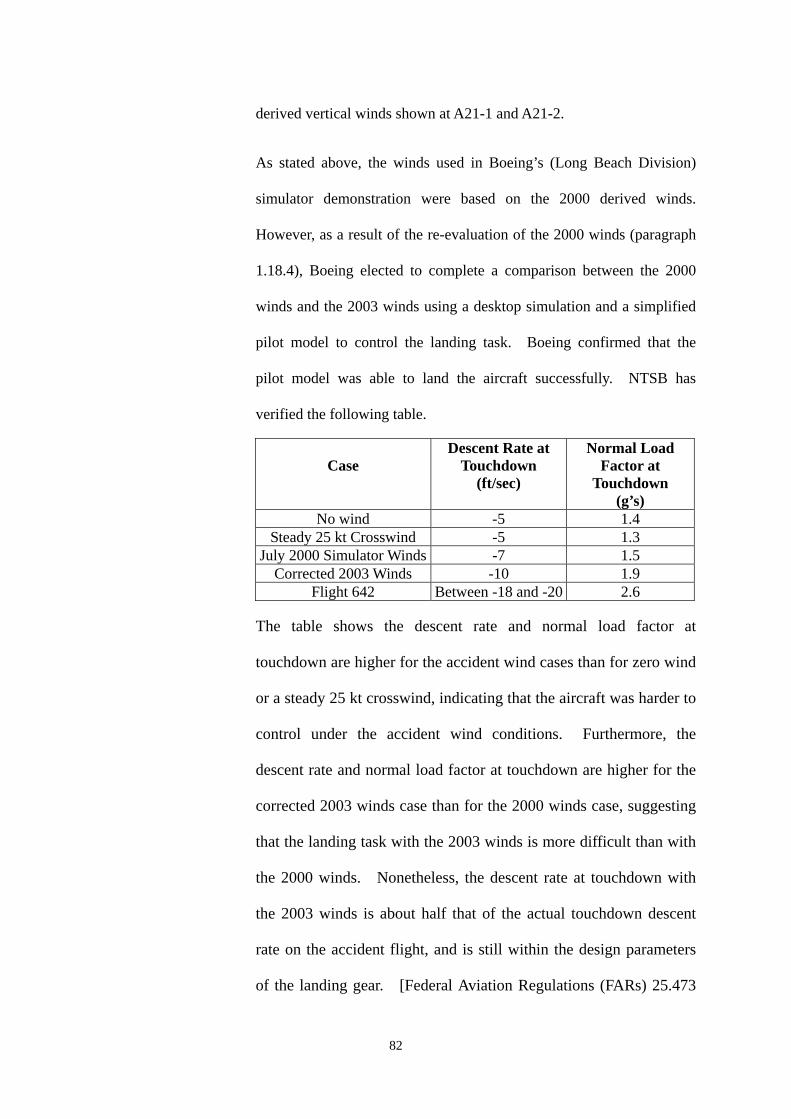
derived vertical winds shown at A21-1 and A21-2.
As stated above, the winds used in Boeing’s (Long Beach Division)
simulator demonstration were based on the 2000 derived winds.
However, as a result of the re-evaluation of the 2000 winds (paragraph
1.18.4), Boeing elected to complete a comparison between the 2000
winds and the 2003 winds using a desktop simulation and a simplified
pilot model to control the landing task. Boeing confirmed that the
pilot model was able to land the aircraft successfully. NTSB has
verified the following table.
Case Descent Rate at
Touchdown (ft/sec)
Normal Load Factor at
Touchdown (g’s)
No wind -5 1.4 Steady 25 kt Crosswind -5 1.3
July 2000 Simulator Winds -7 1.5 Corrected 2003 Winds -10 1.9
Flight 642 Between -18 and -20 2.6
The table shows the descent rate and normal load factor at
touchdown are higher for the accident wind cases than for zero wind
or a steady 25 kt crosswind, indicating that the aircraft was harder to
control under the accident wind conditions. Furthermore, the
descent rate and normal load factor at touchdown are higher for the
corrected 2003 winds case than for the 2000 winds case, suggesting
that the landing task with the 2003 winds is more difficult than with
the 2000 winds. Nonetheless, the descent rate at touchdown with
the 2003 winds is about half that of the actual touchdown descent
rate on the accident flight, and is still within the design parameters
of the landing gear. [Federal Aviation Regulations (FARs) 25.473
82
requires a descent rate of 10 ft/sec to be used in the analysis of
touchdown ground loads at the design landing weight.]
Consequently, the simulations show that, even with the corrected
2003 winds, there does exist a set of flight control inputs that will
land the aircraft safely, and that the weather conditions were not
beyond the performance or control capabilities of the MD11. This
is the same determination reached after the July 2000 simulator
exercise. It will be noted from A21-6 (Segments 1 through 4) that
the Boeing 2003 wind study verified by NTSB∗ indicates the
following:
♦# From 55 ft RA (4½ seconds before impact) to 22 ft RA
(2 seconds before impact) the Rate of Descent (ROD) of CI 642
varied between 1080 ft/min and 900 ft/min, reducing
momentarily to 840 ft/min passing 35 ft RA. From 35 ft RA to
5ft RA the ROD progressively increased to 1200 ft/min with
the elevator deflection changing from 8 degrees elevator down
at 35 ft RA to 1 degree elevator up passing through 22 ft RA
and increasing to 9 degrees elevator up at 5 ft RA. The time
span between 22 ft RA and 5 ft RA was 1½ seconds.
♦# Commensurate with the aforementioned elevator movement,
spoiler movement on the right wing varied between 10 degrees
up and 25- 30 degrees up, with the majority of the latter figures
being prevalent from 25 ft RA to impact.
∗ The NTSB reviewed and concurred with the theory and method used by Boeing to perform the 2003 wind calculations and desktop simulations, but did not attempt to duplicate the numerical results of these computations.
83
♦# From 55ft RA to impact the thrust levers were at idle, with the
engine thrust reducing from 1.02 EPR to 1.0 EPR at 30 ft RA.
♦# The comparisons of 2000 winds and the 2003 winds are shown
at A21-3, A21-4 and individual details of the 2003 winds are
shown at A21-5 to A21-10.
1.18.8. MD11 landing accident – Newark International Airport, USA
On 31 July 1997, a MD11 freighter aircraft was involved in an
accident with similar consequences when landing at Newark
International Airport, New Jersey, USA. In that accident, which
occurred in good weather conditions, the aircraft also suffered
structural failure of the RMLG and right wing rear spar, and came to
rest inverted.
The US National Transportation Safety Board (NTSB) investigation
concluded that the probable cause of the accident was overcontrol of
the aircraft during landing. This involved elevator deflections
varying from 26º ANU to 18º AND, and resulted in an initial
touchdown that become airborne again followed by a heavy second
touchdown during which the structural failure occurred. The
second touchdown was in a 9.5º right wing down attitude with a rate
of descent at the RMLG calculated as 13.5 feet per second.
84
2. ANALYSIS
2.1. Scope
The combined wealth of eye witness reports, recorded data, crew interviews
and wreckage analysis enabled a detailed reconstruction of the process which
led to the accident. The reconstruction draws upon all the available evidence
to define what happened and the order in which significant events occurred.
The serviceability of the aircraft was not in question leading to the deduction
that the causal factors were probably aspects of the weather, and the
performance of the flight crew. Relevant aspects of the weather, the design
of the aircraft, and the airport are identified and analysed before the human
factors are examined in detail. Possible changes and additions to crew
procedures and use of the aircraft systems are reviewed. Throughout the
analysis, factors which may have contributed to the accident are identified and
where applicable, safety recommendations are made. The analysis concludes
with a list of the findings and a summary of the safety recommendations.
2.2. Reconstruction of the accident
2.2.1. Descent and intermediate approach
Flight CI642 appears to have been a routine operation until
approaching top of descent into HKIA. The crew were aware of
the proximity of STS ‘Sam’ to the airport and of its associated
weather conditions. The commander had uplifted extra fuel prior
to departure from Bangkok to allow himself operational flexibility in
terms of either initiating an approach to land, holding, or diverting to
85
one of several available alternate airports in the region. In
consequence, the loadsheet estimated that the aircraft would only be
443 lbs (201 kg) below its MLW if a landing was attempted in Hong
Kong, which would result in a relatively high approach speed. The
commander was also monitoring the surface winds from the regular
ATIS broadcasts for HKIA, and comparing these with the company’s
crosswind limits for the type. The crew were therefore well aware
that an approach to land at HKIA would necessarily involve
demanding and near limiting conditions.
Just after commencing descent, the commander commenced briefing
for an approach to RW 25L but was interrupted by the co-pilot who
was sure that the runway in use was 25R. This mistaken
impression may have been due to the co-pilot hearing another
aircraft ahead requesting an approach to RW 25R, which was later
withdrawn because of a deterioration in visibility on that runway.
After questioning this, the commander continued his briefing but
now referred to RW 25R. Playback of the CVR indicates that the
briefing was diminished by discussion, radio call interruptions and
misunderstanding, and that the description of the approach
procedure appeared to be only a recitation, with the attention of both
pilots being focussed elsewhere. No mention was made of the
warnings on successive ATIS broadcasts of severe turbulence and
significant windshear, or of the commander’s intentions in relation
to such conditions, or his intentions if a landing could not be made
other than a cursory reference to the published missed approach
86
procedure.
As the arrival progressed, the crew continued with their mistaken
impression of the runway in use. It was not until Hong Kong
Approach, who had radar vectored the aircraft through the ILS
localiser for RW 25L to the north for spacing, gave the aircraft a
heading of 230° and cleared it for an ILS approach to 25L that the
pilots realised their mistake. The commander later referred, briefly,
to the minimums for an ILS approach to RW 25L and the relevant
missed approach procedure. Relevant extracts from the CVR
transcript are at Appendix 10.
While the late and sporadic crew briefings for the approach,
including reference to the wrong runway, are not considered to have
contributed directly to the accident, they do have human factors
aspects which are further discussed at paragraph 2.7.2.1.
2.2.2. Final approach
With the autopilot and autothrottle systems engaged, the aircraft
captured the ILS localiser beam and then the glide path. The
approach continued relatively normally for the conditions, the
autoflight system coping adequately with the gusty winds.
At approximately 13 nm on the approach, air traffic control passed
the current surface wind as 330°/26 kt gusting 36 kt which the
commander judged to be in excess of the crosswind limit, but
continued the approach with the intention of rechecking the surface
87
wind as the aircraft descended below 1,000 ft.
Because of the late realisation of which runway was in use and the
fact that the missed approach procedure for runway 25L differs
significantly from that of 25R, the commander then correctly
reviewed the initial missed approach procedure altitude for runway
25L as ‘2000’. The co-pilot mistakenly interjected ‘actually 4500’,
but then agreed with the commander’s insistence that the figure was
‘2000 until 3 mile’.
Prior to reaching 1,000 ft, ATC passed the current surface wind as
320°/25 kt gusting 33 kt, and cleared the aircraft to land. The
commander elected to continue with the intention of requesting a
final wind check below 1,000 ft.
At about 700 ft RA, visual contact with the approach lights was
established and ATC passed a final surface wind check of 320°/28 kt
gusting 36 kt, which indicated a small increase in the steady state
speed and put the crosswind component at 26 kt, 2 kt in excess of
the required limit. Shortly after this, the commander disconnected
the autopilot to fly the aircraft manually but kept the autothrottle
system engaged, in accordance with normal MD11 operating
philosophy. The FDR indicates that the approach continued within
reasonable tolerances, though control activity, particularly aileron,
increased considerably by comparison to that with the autopilot
engaged. The commander later confirmed that his windshield
wiper was selected to the ‘FAST’ position at this stage and that
88
visibility through the windshield was ‘moderate’.
The autothrottle controlled the speed adequately within a four or five
kt tolerance either side of a mean speed of 165 kt until just below
300 ft RA when the indicated airspeed fell to 157 kt. The co-pilot
called ‘Speed’ and claimed to have moved the thrust levers forward
when there was no apparent response from the commander; however,
in a later statement the commander claimed that he had moved the
thrust levers forward. The thrust then increased significantly from
a previous average of 1.05 EPR to almost 1.3 EPR, with a
consequential increase in speed to 175 kt. In response to this
excessive speed the thrust levers were at the fully closed position by
about 70 ft RA, and the thrust decayed to an average of 1.0 EPR by
50 ft RA (the altitude at which the autothrottle would normally
commence thrust lever retard), and to idle thrust by 35 ft AGL.
The commander used the basic crosswind approach technique
described in the MD11 SOP Part 2 page 4. Runway alignment was
maintained by crabbing into wind until approximately 130 ft RA.
After this point, the aircraft’s heading was progressively aligned
with the runway direction of 253°, which was achieved by 50 ft RA,
and sideslip used as recommended to maintain runway alignment.
The commander’s crosswind approach technique is therefore not
considered to be contributory to the accident.
89
Under ‘Landing Techniques’, the MD11 SOP states at Part 1 page
117 that:
‘The recommended landing procedure for the MD11 calls for
reducing the sink rate at approximately 30 feet radio altitude. Only
a 2° attitude change is required to reduce (but not stop) the rate of
descent. As this attitude is being held, power should be slowly
reduced’.
On the actual approach, the attempt made to flare the aircraft after it
passed 50 ft RA, with thrust levers already retarded and
descending increasingly below the GP from its previous one dot low
perspective, was not effective. This involved an initial up elevator
input of 12º at about 45 ft RA, immediately followed by a reversal to
8.5º down, which only succeeded in achieving a momentary increase
in pitch attitude from about 3.5º ANU to 4.2º, then returning to 3.2º.
As the aircraft passed 21 ft RA, up elevator was again applied,
reaching almost 16º immediately before touchdown. While this did
increase the pitch attitude to 4.5º ANU, it did not succeed in
reducing the high rate of descent, which was calculated to be
approximately 18 feet per second at the RMLG as it impacted the
runway. This continuing high rate of descent is evident from
playback of the CVR tape recording, which does not indicate any
slowing in the cadence of the CAWS readouts of ‘50/40/30/20/10’ as
would normally occur in the flare.
90
While the first attempt to flare the aircraft may have been slightly
early, and may have led to some minor overcontrol in pitch, this
could have been prompted by the gusting, turbulent conditions
which prevailed. The aircraft’s loss of 20 kt indicated airspeed
below 50 ft RA, consequent upon a loss of headwind component due
to the varying wind conditions and the early retardation of the thrust
levers, would have resulted in a significant decrease in lift at a
critical stage of the approach; this could only be compensated for by
a marked increase in pitch attitude (as was demonstrated in the flight
simulations described in paragraph 1.18.7) or by an increase in
thrust, or a combination of both. In the event, the commander's
attempt to flare the aircraft by limited use of elevator alone, and
without the application of thrust, was inadequate and proved
unsuccessful in the conditions with which he was contending. Not
only was the recommended change in pitch attitude of 2° not
achieved and then held, but the flight simulations described in
paragraph 1.18.7 indicated that a much greater change would have
been required to successfully flare the aircraft from its increasingly
high rate of descent.
It was therefore recommended to China Airlines that, in association
with the Boeing Company, they amend the recommended landing
procedures in the MD11 SOP to include procedures for approaches
and landings in more demanding weather conditions.
91
2.2.3. The landing and after landing
The first tyre marks identified as possibly having been made by
CI642 were from the right main gear impacting at about 140m
(460 ft) from the RW 25L threshold, and some 11m (35 ft) to the
right of the runway centre line. This was followed by the body
gear apparently impacting about 180m (600 ft) from the threshold
but only 1.5m (4-5 ft) right of the centre line, and later a scrape mark,
thought to be from the no. 3 engine nacelle, commencing some
285m (940 ft) from the threshold and 14m (40 ft) right of the centre
line. These indications tally with FDR data and eye witness
accounts to confirm that the aircraft was well aligned for landing
although slightly right wing low, but touched down considerably
short of the normal aiming point, the marking for which is 400 m
(1,312 ft) from the threshold. The scrape mark curved gently off to
the right and indicated that the aircraft left the runway some 820 m
(2,700 ft) from the threshold. It was during this period when the
aircraft was in the process of departing the runway that, at the
preliminary interview, the co-pilot stated that he called ‘go-around’
but the commander thought that ‘on the ground we are heading
towards the grass and if I do have full power something worse may
happen’. The CVR does not record the co-pilot’s call of
‘go-around’ or if the commander responded verbally, but power
interruption to the CVR may already have occurred.
92
After the aircraft rolled, yawed and came to rest inverted, the
commander stated that he saw fire and attempted to do some
emergency procedures; however, he had difficulty in locating the
fire handle but turned off the engine fuel switches before vacating
the cockpit. He made no reference to altering his windshield wiper
control, which was later found in the ‘OFF’ position with the control
circuit breaker tripped. As the wiper arm was found in an
unparked position after the accident, and all system components
subsequently tested satisfactorily, no conclusions can be drawn that
would substantiate the positions of the commander’s windshield
wiper control and circuit breaker as referred to above.
2.3. Aircraft serviceability
The aircraft was dispatched from Bangkok with only one deferred item in the
Technical Log. This item related to peeling of paint from the right winglet,
and was not significant in the context of the accident.
The wealth of recorded data, coupled with the absence of any reported
handling problem during the approach prior to entering the flare, established
beyond all reasonable doubt that the aircraft controls were responding as
designed to demands made by the commander.
Therefore, the serviceability of the aircraft was not considered to be a
contributory factor to this accident.
93
2.4. Weather
2.4.1. Relevance
The weather conditions associated with STS ‘Sam’, which have
been comprehensively detailed in paragraph 1.7 and the associated
annexes, made approaches to HKIA difficult during the afternoon
and early evening of 22 August 1999. Strong crosswinds, lateral
gusts, severe turbulence, possible windshear and heavy rain all
added to operating flight crew workload. In consequence, of
26 approaches flown in the period of three and three-quarter hours
up to the accident, 10 resulted in go-arounds as a result of the
weather conditions. Analysis of the prevalent weather conditions is
therefore appropriate to establish the possible contribution of these
factors to the accident.
2.4.2. Cloud base
ATIS information ‘X-ray’, current at the time of the accident, gave
the cloud base as FEW at 1,000 ft and SCT (‘scattered’) at 1,600 ft.
By comparison, the ceilometer located near the centre of the airport
recorded the cloud base as fluctuating between 781 and 2,281 ft in
the two minutes before the accident. The co-pilot advised
‘approach light ahead’ to the commander just after the CAWS call
at 1,000 ft and later advised ATC ‘runway in sight around 700 ft’.
Hence, the cloud base was not a contributory factor in this accident.
94
2.4.3. Rain and visibility
ATIS information ‘X-ray’ gave a visibility of 800 m in heavy rain
and a touchdown zone RVR of 650 m for RW 25L; however, a later
touchdown zone RVR of 1,600 m was passed by ATC to the crew at
1041 hr with their landing clearance, some two minutes before the
accident. Braking action was reported as good. The rain gauge
situated near the centre of HKIA recorded 0.1 mm of rainfall in the
five minutes before the accident, which the HKO has categorised as
‘light to moderate’. Sunset was due at 1050 hr.
The commander, in answer to a written query, gave his assessment
of visibility through his windshield on final approach as ‘moderate’.
Despite that assessment, it is possible that the impending sunset,
overcast conditions, and rainwater on the windshields outside the
sweep of the windshield wipers and on the unswept sidewindows,
may have affected his peripheral vision; this may have resulted in
him not appreciating the aircraft’s high rate of descent as it passed
the normal flare height.
Therefore, visibility from the flight deck may have been a
contributory factor to the accident.
2.4.4. Wind conditions
All the forecast and actual weather reports available to the
commander, including those available on the ATIS broadcast, and
the surface wind read by ATC from the RW 25L touchdown
95
anemometer some 40 seconds before the accident, should have left
the commander in no doubt as to the general conditions to expect on
final approach - a strong gusting northwesterly crosswind on the
company limit for a wet runway, severe turbulence and the
possibility of windshear. Indeed, the commander of the B777
aircraft which landed successfully four minutes before the accident
aircraft stated, in a later written report, that he was ‘well aware of
the shear effect that the aircraft would encounter in the final critical
stage of landing’.
Comparison of surface wind records from the four TDZ
anenometers taken over the period encompassing the time of the
accident, demonstrates a differing variation in wind speed and
direction between the anemometer located at 25L TDZ and the other
three TDZ anemometers (A5-3).
Unfortunately, the lack of QAR data meant that the actual winds
experienced by CI642 on its final approach were not readily
available to the investigators as described in paragraph 1.18.4.
However in accordance with the Boeing study (paragraph 1.18.7),
the net effect on CI642 was that the aircraft apparently suffered a
loss of 20 kt airspeed but only 6 kt groundspeed in the last 50 ft of
its approach. Whereas part of this loss may be attributable to early
retardation of the thrust levers (see paragraph 2.2.2), part of the loss
in the airspeed case could also be attributed to a loss of headwind
component in the varying wind conditions.
96
Therefore, the variations in wind conditions experienced by CI642
on its final approach were a probable contributory factor to the
accident.
With reference to Northwesterly through Northeasterly winds (see
paragraph 1.7.10) it was considered that more information should be
provided in the AIP regarding the presence of windshear and
turbulence affecting the approaches and the TDZ areas for RW 25L
and RW 25R during periods of STS.
It is therefore recommended that the HKO should provide CAD with
more advisory meteorological information for inclusion in the AIP
Section VHHH AD 2.23 paragraph 1.3.2.
2.5. Hong Kong International Airport
There were two aspects of the existing infrastructure at HKIA that are
considered to be worthy of comment. These arise from examination of the
surface wind velocities recorded by the RW 25R and 25L touchdown
anemometers, as discussed in paragraph 2.4.4, and involve the location of the
PTB in relation to the touchdown areas of the two runways referred to, and the
unique location of the RW 25L touchdown anemometer.
2.5.1. Location of Passenger Terminal Building
HKIA is a comparatively new airport, having been opened in July
1998, and was designed to comply with all aspects of ICAO
standards or guidelines. In particular, the proximity of buildings to
active runways does meet the standards required by ICAO Annex 14.
97
It is also common knowledge that high terrain or man-made
structures at certain major airports do cause local variations in
certain wind conditions, and that these can affect aircraft on final
approach or immediately after take off, but are within the control
capabilities of modern public transport aircraft.
Despite the variations noted in paragraph 2.4.4 between readings
from the RW 25R and 25L touchdown anemometers, and also in
those extracted from the previous landing aircraft’s QAR and that
derived from CI642’s FDR, the last windshear warning from the
airport’s WTWS for a RW 25L arrival occurred at 1016 hr, some 27
minutes before the accident. While this may have resulted from the
equipment assessing any subsequent windshears as not exceeding its
15 kt design trigger point, both the previous landing aircraft and
CI642 did experience some windshear as they entered the flare.
2.5.2. Location of Runway 25L touchdown anemometer
The location of the RW 25L touchdown anemometer, while unique
compared with the other five anemometers located on the airport
(see paragraph 1.7.7), does meet the guidelines contained in ICAO
Document 8896.
2.6. Flight crew procedures
The remainder of the analysis examines flight crew procedures in respect of
approach briefing, calculation of final approach speed and control of power on
98
the approach.
2.6.1. The approach briefing
‘Crew Briefing’ is the fifth item in the ‘Preparation for Descent
Procedure’ detailed at page NORM-10-33 of China Airlines MD11
FCOM Volume II. However, the briefing was not initiated until
just after descent was commenced, and therefore due to increasing
workload, arising from a combination of factors including
observance of descent constraints, radio communications and
weather avoidance, the briefing became disjointed, inaccurate and
incomplete.
Of the items listed in the ‘Flight Crew Before L/D Briefing’ at page
94 of the MD11 SOP (a plasticised version of which was carried on
the aircraft’s flight deck), those referring to alternate airport,
transition level, MSA (i.e. minimum safe altitude), field elevation,
and aircraft go-around procedure (as opposed to the ATC missed
approach procedure) were not included in the briefing, although
some or all could have been of significance on the subsequent
approach.
In the event, the inadequate approach briefing did not make a direct
contribution to the accident, but did reflect negatively on the
commander’s attitude towards cockpit resource management.
Extracts from the quoted manuals showing the ‘Preparation for
Descent Procedure’ and ‘Flight Crew Before L/D Briefing’ are at
99
Appendix 22.
2.6.2. Calculation of the final approach speed
The landing reference speed (Vref), provided by the aircraft’s flight
management system computer, is determined from the aircraft’s
weight on landing as predicted by the computer and the
crew-entered landing flap setting. This function should be
completed as part of the ‘Preparation for Descent Procedure’
detailed in the MD11 SOP, and provides a basic reference speed to
which additives must be made. In this instance, the commander
determined that the final approach speed should be 170 kt.
2.6.3. Control of power on the approach
The commander of CI642 elected to retain the use of the ATS
throughout the approach. In consequence, as a response to the
increase in speed to 175 kt at about 120 ft, the ATS had begun to
retard the thrust, the throttles reaching the idle position by about
70 ft, so that the aircraft entered the flare with the power already at,
or near, flight idle.
Therefore, the commander of CI642’s failure to override the
autothrottle system and apply power was a contributory factor to the
aircraft’s high rate of descent at touchdown, and therefore to the
accident.
100
2.7. Cockpit resource management
2.7.1. Training requirement
China Airlines has a formal training requirement in Cockpit
Resource Management (CRM) for all its flight deck crew. Both
pilots had completed annual CRM training in the month preceding
the accident.
2.7.2. CRM aspects of the approach
There were three aspects of crew performance prior to or during the
approach which, although not bearing directly on the accident, do
require comment. These were the delay in completing the
approach briefing, the co-pilot’s provision of incorrect information
to the commander during the approach, and the control of power on
the approach.
2.7.2.1. Delayed approach briefing
While some procedural aspects of the delayed approach
briefing have already been discussed in paragraph 2.6.1,
there are other more philosophical aspects which
impinge on good CRM practice.
Thorough planning and briefing is the key to a safe,
unhurried, professional approach, as is well emphasised
in the China Airlines Flight Crew Training Manual for
another of their aircraft types (B747-400). It is normal
101
airline practice to complete the approach briefing late in
the cruise phase of flight but at a suitable time prior to
the descent, when crew activity is at a comparatively
low level. Delaying the briefing into what might
become a very busy descent, as did the commander of
CI642, negates the aims as stated in the B747-400
manual, and puts undue pressure on the crew members
prior to commencing what might well be a very
demanding approach, as proved to be the case for CI642.
It is therefore recommended that China Airlines reminds
its MD11 pilots of the need for an early, complete
approach briefing, and emphasises the rationale for this
in both its CRM training and in the MD11 SOP.
2.7.2.2. Monitoring by the co-pilot
Perhaps as a result of his recent completion of company
CRM training, when the need for good monitoring by
the pilot-not-flying (PNF) would have been emphasised,
there were two occasions during the approach when
incorrect prompting by the co-pilot led the commander
into actions which needlessly added pressure to the
latter in his role both as handling pilot and aircraft
commander.
The first occasion occurred when the co-pilot, who had
just copied ATIS information ‘X-ray’ which included
102
the runway in use as RW 25L, advised the commander,
who had commenced briefing for an approach to RW
25L, that the runway in use was RW 25R. This led the
commander to unnecessarily change the briefing for an
approach to RW 25R. This mistaken impression was
maintained for some 15 minutes of the descent and
intermediate approach, and was only corrected when
ATC radar vectored the aircraft for an ILS approach to
RW 25L, and led to another hasty re-brief.
The second occasion was at about 2,000 ft on the
approach when the commander queried if the co-pilot
was ready for a go-around and correctly quoted the
initial go-around altitude as ‘2000’. To this the
co-pilot interjected ‘actually 4500’, but the commander
insisted, correctly, ‘2000 until 3 mile’, with which the
co-pilot then concurred. Such an unnecessary
distraction at a late stage of the approach, while
comparatively minor itself, detracts from the aim of a
well coordinated crew performance. These interjections
by the co-pilot, coming so soon after he had completed
CRM training, may have arisen from a misplaced
interpretation of the role of the monitoring pilot.
It is therefore recommended that China Airlines reviews
the content of its CRM training course to ensure that
contributions made by the monitoring pilot, in
103
operational situations, are both accurate and
appropriate.
In addition, it may be construed from the CVR that,
after the copilot’s call with regard to the decreasing
indicated air speed (IAS) (at approximately 250 ft above
the ground), his attention became fixed outside the
cockpit. Certainly, the high rate of descent which was
developing near the ground, coupled with the
rapidly-decaying air speed, were not perceived by either
pilot, either by sensory perception or by instrument
indication.
It is further recommended therefore that China Airlines
re-emphasise to flight crews the need, on instrument
approaches, to continue to monitor the flight
instruments as prescribed in the China Airlines Flight
Operations Manual (FOM).
2.7.2.3. Use of the autothrottle system
The potentially confusing references in China Airline’s
operating manuals to use of the autothrottle system have
been discussed in paragraph 2.6.3. In view of the
significance of engine power in this accident, there
would appear to be a need to address not only these
confusing references, but also what may have become
over-reliance by pilots on an automated system.
104
The autothrottle system in the MD11 is a ‘full-time’
system capable of automatically controlling a variety of
parameters of the flight’s progress from the initiation of
the take-off roll until 50 ft RA on final approach, after
which it remains armed but normally inactive unless the
‘go-around’ switch is pressed to discontinue an
approach. The pilot may disconnect the system by
simply pressing a button on the outside of no. 1 or no. 3
thrust lever, or by selecting reverse thrust after landing.
He may also intervene and adjust the thrust temporarily
in flight by manually moving the thrust levers.
Whilst the operations manuals are not explicit regarding
use of the autothrottle system, full time use of the
system is known to have been encouraged by the
manufacturer in operation of MD11 aircraft, and also in
that of its predecessor, the DC 10. As in other areas of
automation on the flight deck, this may encourage
over-reliance on the automated system, to the point
where the pilot may no longer be aware of the need to
intervene when the system is either not coping with the
operating conditions affecting the aircraft, or the
operational situation is outside the system’s design
parameters. One of the pilots did intervene by
advancing the thrust levers when the speed fell to 157 kt
just below 250 ft; however, more critically, the
105
commander did not react to override the early
retardation of the thrust levers and apply thrust to
counteract the increasing rate of descent in the flare, as
the commander of the previously landing aircraft did.
It is therefore recommended that China Airlines should
review its MD11 training syllabuses to ensure that the
crew monitor the automated systems on the flight deck,
so as to be ready to intervene, or override manually,
whenever necessary.
3. CONCLUSIONS
3.1. Findings
3.1.1. Both pilots met the required regulatory licensing and checking
requirements to operate the flight.
3.1.2. The aircraft was properly maintained and serviceable to operate the
flight.
3.1.3. The weather conditions encountered by CI642 were similar to the
forecasts and observations available to the crew.
3.1.4. ATIS information X-ray at time one zero zero six referred to the
runway in use as being runway two five left and that runway two
five right was available on request. It further advised that the pilot
could expect significant windshear and severe turbulence on
approach and departure.
106
3.1.5. The reported visibility/RVR during the approach and landing met
China Airlines’ approach minima.
3.1.6. For more than an hour before the accident, the WTWS had been
issuing turbulence alerts almost continuously for RW25L arrival.
Between 1005 to 1016 hrs, the turbulence alerts were overridden
intermittently by windshear alerts. After 1017 hrs, the WTWS
issued turbulence alerts which remained effective up to the time of
the accident and beyond. No windshear alerts were issued by
WTWS during this period.
3.1.7. The descent clearance was given to CI642 at 1014. Shortly after
commencing descent at 1017, the commander commenced the
approach briefing for the wrong runway. No mention was made of
the warnings of severe turbulence or significant windshear, or that
the ATIS reported that RW 25R was available. This briefing given
by the commander did not meet the China Airlines Operations
Manual requirements in respect of either timing or content.
3.1.8. The co-pilot twice provided incorrect information to the commander
during the descent and approach.
3.1.9. The approach was de-stabilised at about 250 ft by an excessive
application of power, which increased the indicated airspeed to
175 kt, 15 kt above the correct final approach speed.
107
3.1.10. The commander used the crosswind landing approach technique
recommended in the MD11 SOP, and had the aircraft correctly
aligned in azimuth as it approached the flare.
3.1.11. The thrust levers began to retard towards the idle stop at 135 ft RA,
reaching that position by 70 ft. Consequently, the thrust
progressively reduced to flight idle by 35 ft where it remained to
touchdown.
3.1.12. During the last thirteen seconds of flight, from approximately 150 ft
RA, to touchdown, the aircraft’s rate of descent varied between
1,200 ft/min and 240 ft/min. At 30 ft it was approximately
770 ft/min and progressively increased to 1,080 ft/min at touchdown.
3.1.13. Visibility from the flight deck may have contributed to the
commander’s failure to appreciate the increasing rate of descent
prior to touchdown.
3.1.14. Neither pilot perceived the increasing rate of descent and decreasing
indicated airspeed as the aircraft approached the landing flare.
3.1.15. The commander’s attempt to flare the aircraft by initiating a small
increase in pitch attitude, as prescribed in the MD11 Standard
Operation Procedure (SOP) Manual was in the circumstances
ineffective.
3.1.16. The maximum allowable landing weight for MD11, Registration
B-150, was 430,000 lbs (195,454 kg). The estimated landing
weight for CI642 at the time of the accident was 429,557 lbs
108
(195,253 kg), therefore the aircraft approached the flare only 443 lb
(201 kg) below maximum landing weight, with the thrust levers
already fully retarded which, in combination with a probable loss of
headwind component, led to a loss of airspeed of 20 kt and an
increasing rate of descent which reached approximately 18 feet per
second at touchdown.
3.1.17. QAR information relating to the final 500 feet of the approach was
lost due to the interruption of the power supply at impact, which
caused loss of data in the volatile buffer storage.
3.1.18. At the time of the accident, the anemometer at the touchdown zone
of RW25R had recorded wind speeds and direction over a period of
time, which remained relatively constant. However, over the same
period of time, the wind speeds and direction recorded at RW25L
showed periodic variations which on occasions were significant.
3.1.19. The aircraft touched down slightly right wing low (3.5-4°) on its
right main landing gear at a rate of descent calculated as
approximately 18 feet per second, well beyond the design structural
limit of 12 feet per second.
3.1.20. The energy transmitted into the right main landing gear at
touchdown exceeded the MD11’s maximum certificated landing
energy and was sufficient to fully compress (bottom) the right main
landing gear strut exceeding the entire design margin, and to cause
structural failure of the forward trunnion bolt and rear spar shear
web.
109
3.1.21. The structural failure of the right wing rear spar resulted in the
rupture of the right wing fuel tanks and subsequent fire.
3.1.22. The aircraft suffered extensive structural damage during its rolling
and yawing movement following detachment of the right wing.
3.1.23. Subsequent tests and analysis indicated that the failures in the
aircraft’s structure were due to ductile overload and not to causes
other than the accident.
3.1.24. Rescue services were on the scene within about one minute and
immediately commenced fire-fighting and then rescue operations.
3.1.25. Passengers were evacuated through doors L3 and R1 and through a
hole in the aircraft skin aft of door L2, and later through doors R2
and R4.
3.1.26. Some 200 passengers were rescued and led to safety within 8
minutes of the arrival at the scene of the rescue services. The
remaining passengers left the aircraft in the early stages of the
evacuation either unassisted or assisted by other passengers or crew
members.
3.1.27. Two passengers died in the accident and one later in hospital, while
50 passengers and crewmembers received serious injuries and 153
received minor injuries.
3.1.28. Some passengers reported that there were not enough temporary
shelters available, and that they had to stand in the open in heavy
110
rain for 20 to 30 minutes.
3.2. Causal factors
3.2.1. The cause of the accident was the commander’s inability to arrest the
high rate of descent existing at 50 ft RA.
3.2.2. Probable contributory causes to the high rate of descent were:
(i) The commander’s failure to appreciate the combination of a
reducing airspeed, increasing rate of descent, and with the
thrust decreasing to flight idle.
(ii) The commander’s failure to apply power to counteract the
high rate of descent prior to touchdown.
(iii) Probable variations in wind direction and speed below 50 ft
RA may have resulted in a momentary loss of headwind
component and, in combination with the early retardation of
the thrust levers, and at a weight only just below the
maximum landing weight, led to a 20 kt loss in indicated
airspeed just prior to touchdown.
3.2.3. A possible contributory cause may have been a reduction in
peripheral vision as the aircraft entered the area of the landing flare,
resulting in the commander not appreciating the high rate of descent
prior to touchdown.
111
4. RECOMMENDATIONS
As a result of the investigations, the following recommendations are made:
4.1. China Airlines should remind its MD11 pilots of the need for an early and
complete approach briefing (paragraph 2.7.2.1).
4.2. China Airlines should review the content of its CRM training course to ensure
that contributions made by the monitoring pilot, in operational situations, are
both accurate and appropriate (paragraph 2.7.2.2).
4.3. China Airlines should review its MD11 training syllabuses to ensure the crew
monitor the automated systems on the flight deck, so as to be ready to
intervene, or override manually, whenever necessary (paragraph 2.7.2.3).
4.4. China Airlines should consider the introduction of a ‘Flight Instructor Guide’
of a type used by other MD11 operators and which includes advice to training
staff on techniques to be followed during crosswind landings (paragraph
1.18.1).
4.5. China Airlines should, in association with the Boeing Company, amend the
recommended landing procedures in the MD11 SOP to include procedures for
approaches and landings in more demanding weather conditions (paragraph
2.2.2).
4.6. China Airlines should ensure that crosswind landing limitations noted in its
publications are consistent throughout (paragraph 1.18.1).
112
4.7. China Airlines should re-emphasise to flight crews the need on instrument
approaches, to continue to monitor the flight instruments in the final stages of
the approach as prescribed in the China Airlines Flight Operations Manual
(FOM) (paragraph 2.7.2.2).
4.8. The Boeing Company and the equipment vendor should conduct a study to
examine methods for preventing the loss of QAR data in the event the
equipment is switched off in a non standard way such as by an interruption to
the power supply (paragraphs 1.11.4/1.18.4).
4.9. CAD should give consideration to the installation of equipment, such as video
recorders, to monitor the touch down zones of Runways 25 R/L and 07 R/L
(paragraph 1.18.5).
4.10. With reference to local wind effects, HKO should provide information
regarding the character of airflow in the vicinity of the TDZ of RW 25L and
RW 25R in conditions of severe tropical storms and, in particular, when the
wind directions are between northwest, through north, to south with the
purpose of providing the CAD with further advisory meteorological
information to be included in the Hong Kong AIP (paragraph 2.4.4 and 2.5.1).
These recommendations are addressed to the regulatory authority or concerned party, having
responsibility for the matters with which the particular recommendation is concerned. It is
for that authority or party, to decide whether and what action is taken.
113
ACKNOWLEDGEMENT
The invaluable contributions of the Aviation Safety Council, Air Accident Investigation
Branch (UK), the National Transportation Safety Board (USA) and The Boeing Commercial
Airplane Group, Long Beach are gratefully acknowledged.
Y.K. LEUNG
Inspector of Accidents
Accident Investigation Division
Civil Aviation Department
Hong Kong Special Administrative Region
China
114