Embed Size (px)
Citation preview
7© Crown copyright 2013
AAIB Bulletin: 10/2013 AAIB Bulletin: 10/2013 G-DRFC EW/C2012/06/01
ACCIDENT
Aircraft Type and Registration: ATR 42-320, G-DRFC
No & Type of Engines: 2 Pratt & Whitney Canada PW121 turboprop engines
Year of Manufacture: 1986 (Serial no: 7)
Date & Time (UTC): 16 June 2012 at 0723 hrs
Location: Jersey Airport, Jersey, Channel Islands
Type of Flight: Commercial Air Transport (Passenger)
Persons on Board: Crew - 3 Passengers - 40
Injuries: Crew - None Passengers - 4 (minor)
Nature of Damage: Left main landing gear, wingtip, fuselage skin, and left propeller damaged
Commander’s Licence: Airline Transport Pilot’s Licence
Commander’s Age: 49 years
Commander’s Flying Experience: 6,106 hours (of which 1,255 were on type) Last 90 days - 103 hours Last 28 days - 49 hours
Information Source: AAIB Field Investigation
Synopsis
The aircraft suffered a main landing gear collapse
following an uneventful approach to land. It was
determined that the left side brace upper arm had
suffered a fatigue failure. The failure rendered the side
brace ineffective and the unrestrained main trunnion
continued to translate outboard, leading to the collapse
of the gear. The aluminium brace was found to contain a
small metallurgical feature at the crack origin which was
consistent with titanium rich particles (TiB2) particles
which are introduced as a grain refiner during casting
of the billet prior to forging. The size of the feature
was within the defined specifications for AL7010-T74.
Analysis of the area surrounding the crack origin
revealed an area of static loading before propagating
a crack in fatigue, indicating that there may have been
a single overload event at some point in the history of
the side brace upper arm. The aircraft manufacturer
determined that failure of the brace late in a take-off
run is hazardous under EASA certification specification
(CS) 25.1309.
History of the flight
The crew, comprising a commander, co-pilot and cabin
crewmember, reported for duty at 0620 hrs at Guernsey
Airport. The commander was conducting line training
of the co-pilot, a first officer who had recently joined the
company.
8© Crown copyright 2013
AAIB Bulletin: 10/2013 AAIB Bulletin: 10/2013 G-DRFC EW/C2012/06/01
The first sector was to be from Guernsey to Jersey. No problems were identified during the pre-flight preparation and the aircraft departed on time at 0705 hrs, with the commander acting as handling pilot.
The short flight was without incident and the weather for landing was reported as good, with the wind from 210° at 16 kt, FEW1 cloud at 2,000 ft and visibility in excess of 10 km. The commander elected to carry out a visual approach to Runway 27 at Jersey, using a planned approach speed of 107 kt and flap 30 selected for landing. During the approach, the gear was selected down and the flight crew confirmed the three green ‘gear safe’ indication lights were illuminated, indicating that the gear was locked in the down position. The commander reported that both the approach and touchdown seemed normal, with the crosswind from the left resulting in the left main gear touching first.
Just after touchdown both pilots heard a noise and the commander stated the aircraft appeared to settle slightly differently from usual. This made him believe that a tyre had burst. The cabin crewmember also heard a noise after touchdown which she too thought was from a tyre bursting. The commander selected ground idle and partial reverse pitch and, as the aircraft decelerated through 70 kt, the co-pilot took over control of the ailerons, as per standard procedures, to allow the commander to take control of the steering tiller. The co-pilot reported that despite applying corrective inputs the aircraft continued rolling to the left. A member of ground operations staff, situated at Holding Point E, reported to the tower controller2 that the left landing gear leg of the aircraft did not appear to be down properly as it passed him.
Footnote
1 1-2 oktas (eighths) cloud cover.2 The tower controller was also controlling ground movements on the tower frequency as the ground frequency was not in use.
The aircraft continued to quickly roll to the left until the left wingtip and propeller contacted the runway.
The aircraft remained on the runway, rapidly coming to a halt to the left of the centreline, approximately abeam Holding Point D. Both propellers continued to rotate and the commander selected the condition levers to the fuel shutoff position and pulled the fire handles to shut both engines down. The tower controller, seeing the incident, pressed the crash alarm and airfield emergency services were quickly in attendance.
Aircraft evacuation - cabin
As the aircraft begun to roll to the left after touchdown, some of the passengers, concerned about the situation, moved from their seats. In particular, they reported being concerned by a smell of burning. The cabin crewmember quickly instructed them to sit down again but, once the aircraft came to a halt, passengers left their seats and started to move towards the main exit at the rear of the cabin, next to where the cabin crewmember was seated. She realised the aircraft had suffered some kind of accident and that it would be difficult to contact the pilots whilst trying to control the passengers wishing to leave the aircraft. Knowing the engines had stopped she therefore decided to initiate an evacuation.3 She opened the main door which, due to the angle of the aircraft and the fact the door was hinged at the bottom, could not be opened fully. As the steps are integrated into the door for normal use, this presented an awkward surface for the passengers to negotiate. However, all the passengers were able to vacate the aircraft through the door. One of the passengers had also opened the forward right cabin emergency exit during the evacuation, although it was not used.
Footnote
3 Operations manual Part E, Section 4.6.3 gives instructions for cabin crew to initiate an evacuation if necessary.
9© Crown copyright 2013
AAIB Bulletin: 10/2013 AAIB Bulletin: 10/2013 G-DRFC EW/C2012/06/01
Aircraft evacuation – flight deck
Once the commander had shut down both engines he began to assess the situation, aware that the aircraft had suffered an obvious failure, the exact nature of which was not immediately apparent. He decided to order an evacuation and started to make an announcement on the Passenger Address system. However, as he did so he could see through his side window that passengers were already leaving the aircraft so he did not continue with the message. He returned to ensuring the aircraft had been made safe, assisted by the co-pilot. They reported they did not refer to the Quick Reference Handbook (QRH) as no one checklist seemed immediately appropriate.
There were no signs of fire apparent to the commander. He attempted to contact the fire crew by radio on 121.6 MHz4 to seek further reassurance and to inform them of the status of the aircraft, but received no response.
Having helped secure the aircraft, the co-pilot left the flight deck to assist the cabin crewmember with the passengers outside. The commander switched off the battery power and walked through the cabin ensuring everyone had left the aircraft before evacuating and joining the passengers on the runway.
The crew and passengers, some of whom had sustained minor injuries, were then transported to the designated emergency reception centre within the terminal building.
Quick Reference Handbook (QRH) Checklist
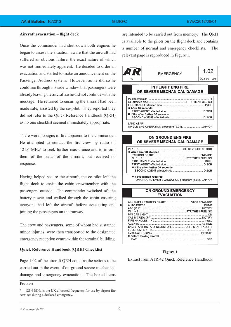
Page 1.02 of the aircraft QRH contains the actions to be carried out in the event of on-ground severe mechanical damage and emergency evacuation. The boxed items
Footnote
4 121.6 MHz is the UK allocated frequency for use by airport fire services during a declared emergency.
are intended to be carried out from memory. The QRH is available to the pilots on the flight deck and contains a number of normal and emergency checklists. The relevant page is reproduced in Figure 1.
Figure 1
Extract from ATR 42 Quick Reference Handbook
10© Crown copyright 2013
AAIB Bulletin: 10/2013 AAIB Bulletin: 10/2013 G-DRFC EW/C2012/06/01
Recorded data
The aircraft was fitted with a tape-based 25-hour Flight Data Recorder (FDR) and a solid state two-hour Cockpit Voice Recorder (CVR); both recorders captured the accident.
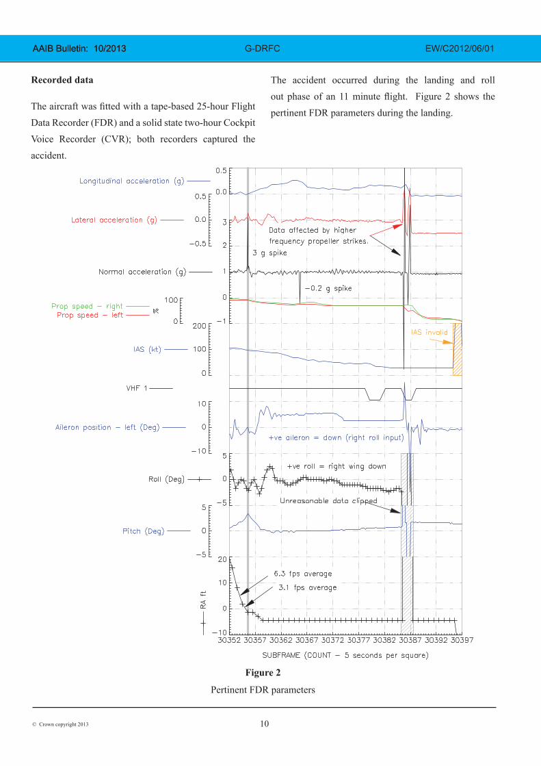
The accident occurred during the landing and roll out phase of an 11 minute flight. Figure 2 shows the pertinent FDR parameters during the landing.
Figure 2
Pertinent FDR parameters
11© Crown copyright 2013
AAIB Bulletin: 10/2013 AAIB Bulletin: 10/2013 G-DRFC EW/C2012/06/01
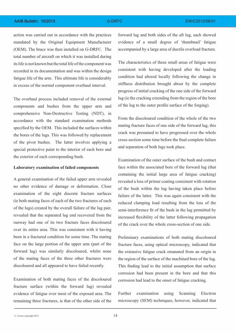
The FDR recorded a 3g normal acceleration spike on touchdown, significantly higher than would be expected during a landing. However, the recorded radio altitude profile indicated a descent rate averaging approximately 3.1 fps over the second just prior to touchdown which was only slightly higher than normal when compared to ten other flights recorded by the FDR. These calculated descent rate figures have limitations due to the low sample rate of once per second; the final height loss may have occurred within a shorter period than the one second between samples.
An isolated -0.2g spike in normal acceleration was recorded approximately 10 seconds after touchdown. No other parameter activity was associated with this spike. Many isolated spikes, that are also similar in value, are present throughout the FDR recording, in flight and on the ground. These are not considered real events. A similar comparison for the 3g spike recorded on landing showed that the other high value spikes were all associated with spikes in other parameters that were not evident during the landing and were likely to be associated with power interrupts. This indicates that the 3g normal acceleration spike is genuine.
Approximately 30 seconds after touchdown many of the parameters became briefly erratic. This is associated with the recorded dip in left propeller speed for a couple of seconds and is likely to be due to the high energy vibrations of the propeller blades striking the runway.
Examination of aircraft
On initial examination, it was found that the left landing-gear had collapsed allowing the wing-tip and rotating propeller to come into contact with the runway surface. A fractured metallic component, identified as part of an attachment lug, was reported to have been found on the runway near the touchdown area.
Landing gear description
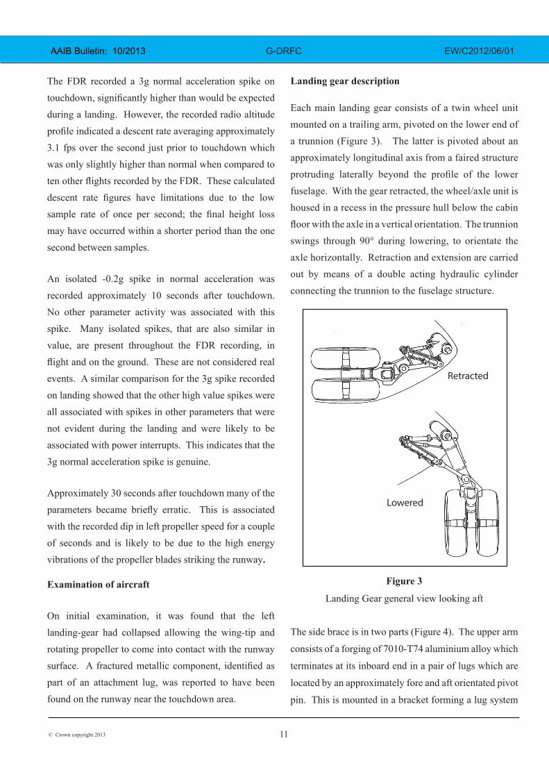
Each main landing gear consists of a twin wheel unit mounted on a trailing arm, pivoted on the lower end of a trunnion (Figure 3). The latter is pivoted about an approximately longitudinal axis from a faired structure protruding laterally beyond the profile of the lower fuselage. With the gear retracted, the wheel/axle unit is housed in a recess in the pressure hull below the cabin floor with the axle in a vertical orientation. The trunnion swings through 90° during lowering, to orientate the axle horizontally. Retraction and extension are carried out by means of a double acting hydraulic cylinder connecting the trunnion to the fuselage structure.
Retracted
Lowered
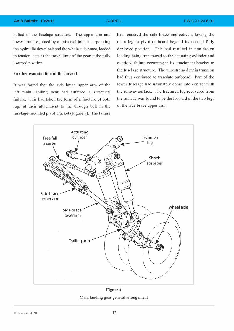
The side brace is in two parts (Figure 4). The upper arm
consists of a forging of 7010-T74 aluminium alloy which
terminates at its inboard end in a pair of lugs which are
located by an approximately fore and aft orientated pivot
pin. This is mounted in a bracket forming a lug system
Figure 3
Landing Gear general view looking aft
12© Crown copyright 2013
AAIB Bulletin: 10/2013 AAIB Bulletin: 10/2013 G-DRFC EW/C2012/06/01
bolted to the fuselage structure. The upper arm and lower arm are joined by a universal joint incorporating the hydraulic downlock and the whole side brace, loaded in tension, acts as the travel limit of the gear at the fully lowered position.
Further examination of the aircraft
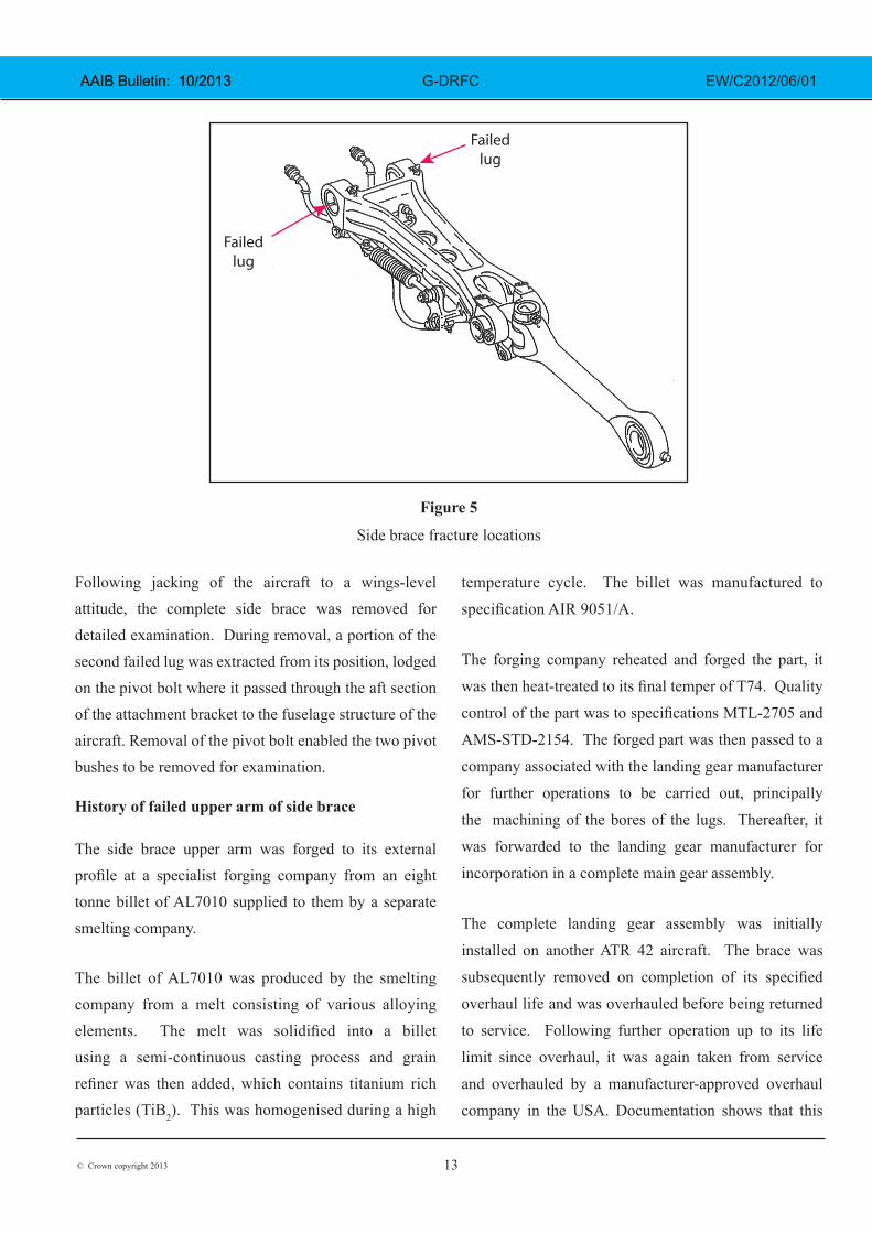
It was found that the side brace upper arm of the left main landing gear had suffered a structural failure. This had taken the form of a fracture of both lugs at their attachment to the through bolt in the fuselage-mounted pivot bracket (Figure 5). The failure
had rendered the side brace ineffective allowing the main leg to pivot outboard beyond its normal fully deployed position. This had resulted in non-design loading being transferred to the actuating cylinder and overload failure occurring in its attachment bracket to the fuselage structure. The unrestrained main trunnion had thus continued to translate outboard. Part of the lower fuselage had ultimately come into contact with the runway surface. The fractured lug recovered from the runway was found to be the forward of the two lugs of the side brace upper arm.
Free fallassister
Actuatingcylinder
Side braceupper arm
Side bracelowerarm
Trailing arm
Shockabsorber
Trunnionleg
Wheel axle
Figure 4
Main landing gear general arrangement
13© Crown copyright 2013
AAIB Bulletin: 10/2013 AAIB Bulletin: 10/2013 G-DRFC EW/C2012/06/01
Following jacking of the aircraft to a wings-level attitude, the complete side brace was removed for detailed examination. During removal, a portion of the second failed lug was extracted from its position, lodged on the pivot bolt where it passed through the aft section of the attachment bracket to the fuselage structure of the aircraft. Removal of the pivot bolt enabled the two pivot bushes to be removed for examination.
History of failed upper arm of side brace
The side brace upper arm was forged to its external profile at a specialist forging company from an eight tonne billet of AL7010 supplied to them by a separate smelting company.
The billet of AL7010 was produced by the smelting company from a melt consisting of various alloying elements. The melt was solidified into a billet using a semi-continuous casting process and grain refiner was then added, which contains titanium rich particles (TiB2). This was homogenised during a high
temperature cycle. The billet was manufactured to
specification AIR 9051/A.
The forging company reheated and forged the part, it
was then heat-treated to its final temper of T74. Quality
control of the part was to specifications MTL-2705 and
AMS-STD-2154. The forged part was then passed to a
company associated with the landing gear manufacturer
for further operations to be carried out, principally
the machining of the bores of the lugs. Thereafter, it
was forwarded to the landing gear manufacturer for
incorporation in a complete main gear assembly.
The complete landing gear assembly was initially
installed on another ATR 42 aircraft. The brace was
subsequently removed on completion of its specified
overhaul life and was overhauled before being returned
to service. Following further operation up to its life
limit since overhaul, it was again taken from service
and overhauled by a manufacturer-approved overhaul
company in the USA. Documentation shows that this
Failedlug
Failedlug
Figure 5
Side brace fracture locations
14© Crown copyright 2013
AAIB Bulletin: 10/2013 AAIB Bulletin: 10/2013 G-DRFC EW/C2012/06/01
action was carried out in accordance with the practices
mandated by the Original Equipment Manufacturer
(OEM). The brace was then installed on G-DRFC. The
total number of aircraft on which it was installed during
its life is not known but the total life of the component was
recorded in its documentation and was within the design
fatigue life of the arm. This ultimate life is considerably
in excess of the normal component overhaul interval.
The overhaul process included removal of the external
components and bushes from the upper arm and
comprehensive Non-Destructive Testing (NDT), in
accordance with the standard examination methods
specified by the OEM. This included the surfaces within
the bores of the lugs. This was followed by replacement
of the pivot bushes. The latter involves applying a
special protective paint to the interior of each bore and
the exterior of each corresponding bush.
Laboratory examination of failed components
A general examination of the failed upper arm revealed
no other evidence of damage or deformation. Close
examination of the eight discrete fracture surfaces
(ie both mating faces of each of the two fractures of each
of the lugs) created by the overall failure of the lug pair,
revealed that the separated lug end recovered from the
runway had one of its two fracture faces discoloured
over its entire area. This was consistent with it having
been in a fractured condition for some time. The mating
face on the large portion of the upper arm (part of the
forward lug) was similarly discoloured, whilst none
of the mating faces of the three other fractures were
discoloured and all appeared to have failed recently.
Examination of both mating faces of the discoloured
fracture surface (within the forward lug) revealed
evidence of fatigue over most of the exposed area. The
remaining three fractures, ie that of the other side of the
forward lug and both sides of the aft lug, each showed evidence of a small degree of ‘thumbnail’ fatigue accompanied by a large area of ductile overload fracture. The characteristics of these small areas of fatigue were consistent with having developed after the loading condition had altered locally following the change in stiffness distribution brought about by the complete progress of initial cracking of the one side of the forward lug (ie the cracking extending from the region of the bore of the lug to the outer profile surface of the forging).
From the discoloured condition of the whole of the two mating fracture faces of one side of the forward lug, this crack was presumed to have progressed over the whole cross-section some time before the final complete failure and separation of both lugs took place.
Examination of the outer surface of the bush and contact face within the associated bore of the forward lug (that containing the initial large area of fatigue cracking) revealed a loss of primer coating consistent with rotation of the bush within the lug having taken place before failure of the latter. This was again consistent with the reduced clamping load resulting from the loss of the semi-interference fit of the bush in the lug permitted by increased flexibility of the latter following propagation of the crack over the whole cross-section of one side.
Preliminary examinations of both mating discoloured fracture faces, using optical microscopy, indicated that the extensive fatigue crack emanated from an origin in the region of the surface of the machined bore of the lug. This finding lead to the initial assumption that surface corrosion had been present in the bore and that this corrosion had lead to the onset of fatigue cracking.
Further examination using Scanning Electron microscopy (SEM) techniques, however, indicated that
15© Crown copyright 2013
AAIB Bulletin: 10/2013 AAIB Bulletin: 10/2013 G-DRFC EW/C2012/06/01
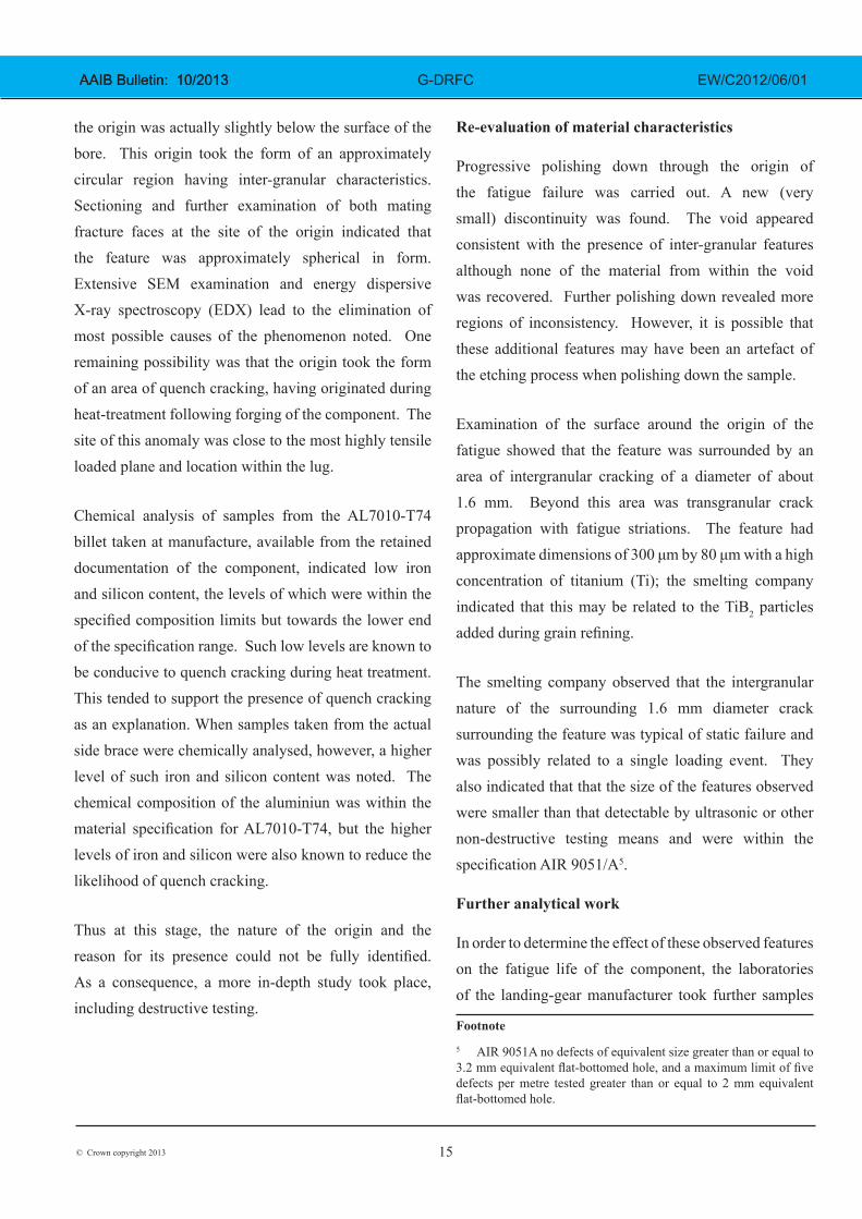
the origin was actually slightly below the surface of the bore. This origin took the form of an approximately circular region having inter-granular characteristics. Sectioning and further examination of both mating fracture faces at the site of the origin indicated that the feature was approximately spherical in form. Extensive SEM examination and energy dispersive X-ray spectroscopy (EDX) lead to the elimination of most possible causes of the phenomenon noted. One remaining possibility was that the origin took the form of an area of quench cracking, having originated during heat-treatment following forging of the component. The site of this anomaly was close to the most highly tensile loaded plane and location within the lug.
Chemical analysis of samples from the AL7010-T74 billet taken at manufacture, available from the retained documentation of the component, indicated low iron and silicon content, the levels of which were within the specified composition limits but towards the lower end of the specification range. Such low levels are known to be conducive to quench cracking during heat treatment. This tended to support the presence of quench cracking as an explanation. When samples taken from the actual side brace were chemically analysed, however, a higher level of such iron and silicon content was noted. The chemical composition of the aluminiun was within the material specification for AL7010-T74, but the higher levels of iron and silicon were also known to reduce the likelihood of quench cracking.
Thus at this stage, the nature of the origin and the reason for its presence could not be fully identified. As a consequence, a more in-depth study took place, including destructive testing.
Re-evaluation of material characteristics
Progressive polishing down through the origin of the fatigue failure was carried out. A new (very small) discontinuity was found. The void appeared consistent with the presence of inter-granular features although none of the material from within the void was recovered. Further polishing down revealed more regions of inconsistency. However, it is possible that these additional features may have been an artefact of the etching process when polishing down the sample.
Examination of the surface around the origin of the fatigue showed that the feature was surrounded by an area of intergranular cracking of a diameter of about 1.6 mm. Beyond this area was transgranular crack propagation with fatigue striations. The feature had approximate dimensions of 300 μm by 80 μm with a high concentration of titanium (Ti); the smelting company indicated that this may be related to the TiB2 particles added during grain refining.
The smelting company observed that the intergranular nature of the surrounding 1.6 mm diameter crack surrounding the feature was typical of static failure and was possibly related to a single loading event. They also indicated that that the size of the features observed were smaller than that detectable by ultrasonic or other non-destructive testing means and were within the specification AIR 9051/A5.
Further analytical work
In order to determine the effect of these observed features on the fatigue life of the component, the laboratories of the landing-gear manufacturer took further samples
Footnote
5 AIR 9051A no defects of equivalent size greater than or equal to 3.2 mm equivalent flat-bottomed hole, and a maximum limit of five defects per metre tested greater than or equal to 2 mm equivalent flat-bottomed hole.
16© Crown copyright 2013
AAIB Bulletin: 10/2013 AAIB Bulletin: 10/2013 G-DRFC EW/C2012/06/01
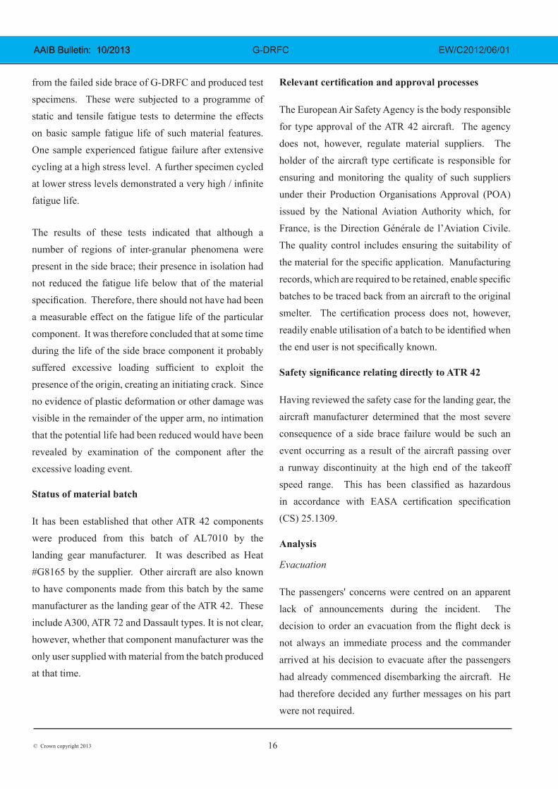
from the failed side brace of G-DRFC and produced test specimens. These were subjected to a programme of static and tensile fatigue tests to determine the effects on basic sample fatigue life of such material features. One sample experienced fatigue failure after extensive cycling at a high stress level. A further specimen cycled at lower stress levels demonstrated a very high / infinite fatigue life.
The results of these tests indicated that although a number of regions of inter-granular phenomena were present in the side brace; their presence in isolation had not reduced the fatigue life below that of the material specification. Therefore, there should not have had been a measurable effect on the fatigue life of the particular component. It was therefore concluded that at some time during the life of the side brace component it probably suffered excessive loading sufficient to exploit the presence of the origin, creating an initiating crack. Since no evidence of plastic deformation or other damage was visible in the remainder of the upper arm, no intimation that the potential life had been reduced would have been revealed by examination of the component after the excessive loading event.
Status of material batch
It has been established that other ATR 42 components were produced from this batch of AL7010 by the landing gear manufacturer. It was described as Heat #G8165 by the supplier. Other aircraft are also known to have components made from this batch by the same manufacturer as the landing gear of the ATR 42. These include A300, ATR 72 and Dassault types. It is not clear, however, whether that component manufacturer was the only user supplied with material from the batch produced at that time.
Relevant certification and approval processes
The European Air Safety Agency is the body responsible
for type approval of the ATR 42 aircraft. The agency
does not, however, regulate material suppliers. The
holder of the aircraft type certificate is responsible for
ensuring and monitoring the quality of such suppliers
under their Production Organisations Approval (POA)
issued by the National Aviation Authority which, for
France, is the Direction Générale de l’Aviation Civile.
The quality control includes ensuring the suitability of
the material for the specific application. Manufacturing
records, which are required to be retained, enable specific
batches to be traced back from an aircraft to the original
smelter. The certification process does not, however,
readily enable utilisation of a batch to be identified when
the end user is not specifically known. Safety significance relating directly to ATR 42
Having reviewed the safety case for the landing gear, the
aircraft manufacturer determined that the most severe
consequence of a side brace failure would be such an
event occurring as a result of the aircraft passing over
a runway discontinuity at the high end of the takeoff
speed range. This has been classified as hazardous
in accordance with EASA certification specification
(CS) 25.1309.
Analysis
Evacuation
The passengers' concerns were centred on an apparent
lack of announcements during the incident. The
decision to order an evacuation from the flight deck is
not always an immediate process and the commander
arrived at his decision to evacuate after the passengers
had already commenced disembarking the aircraft. He
had therefore decided any further messages on his part
were not required.
17© Crown copyright 2013
AAIB Bulletin: 10/2013 AAIB Bulletin: 10/2013 G-DRFC EW/C2012/06/01
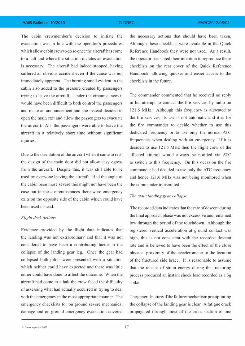
The cabin crewmember’s decision to initiate the
evacuation was in line with the operator’s procedures
which allow cabin crew to do so once the aircraft has come
to a halt and where the situation dictates an evacuation
is necessary. The aircraft had indeed stopped, having
suffered an obvious accident even if the cause was not
immediately apparent. The burning smell evident in the
cabin also added to the pressure created by passengers
trying to leave the aircraft. Under the circumstances it
would have been difficult to both control the passengers
and make an announcement and she instead decided to
open the main exit and allow the passengers to evacuate
the aircraft. All the passengers were able to leave the
aircraft in a relatively short time without significant
injuries.
Due to the orientation of the aircraft when it came to rest,
the design of the main door did not allow easy egress
from the aircraft. Despite this, it was still able to be
used by everyone leaving the aircraft. Had the angle of
the cabin been more severe this might not have been the
case but in these circumstances there were emergency
exits on the opposite side of the cabin which could have
been used instead.
Flight deck actions
Evidence provided by the flight data indicates that
the landing was not extraordinary and that it was not
considered to have been a contributing factor in the
collapse of the landing gear leg. Once the gear had
collapsed both pilots were presented with a situation
which neither could have expected and there was little
either could have done to affect the outcome. When the
aircraft had come to a halt the crew faced the difficulty
of assessing what had actually occurred in trying to deal
with the emergency in the most appropriate manner. The
emergency checklists for on ground severe mechanical
damage and on ground emergency evacuation covered
the necessary actions that should have been taken.
Although these checklists were available in the Quick
Reference Handbook they were not used. As a result,
the operator has stated their intention to reproduce these
checklists on the rear cover of the Quick Reference
Handbook, allowing quicker and easier access to the
checklists in the future.
The commander commented that he received no reply
in his attempt to contact the fire services by radio on
121.6 MHz. Although this frequency is allocated to
the fire services, its use is not automatic and it is for
the fire commander to decide whether to use this
dedicated frequency or to use only the normal ATC
frequencies when dealing with an emergency. If it is
decided to use 121.6 MHz then the flight crew of the
affected aircraft would always be notified via ATC
to switch to this frequency. On this occasion the fire
commander had decided to use only the ATC frequency
and hence 121.6 MHz was not being monitored when
the commander transmitted.
The main landing gear collapse
The recorded data indicates that the rate of descent during
the final approach phase was not excessive and remained
low through the period of the touchdown. Although the
registered vertical acceleration at ground contact was
high, this is not consistent with the recorded descent
rate and is believed to have been the effect of the close
physical proximity of the accelerometer to the location
of the fractured side brace. It is reasonable to assume
that the release of strain energy during the fracturing
process produced an instant shock load recorded as a 3g
spike.
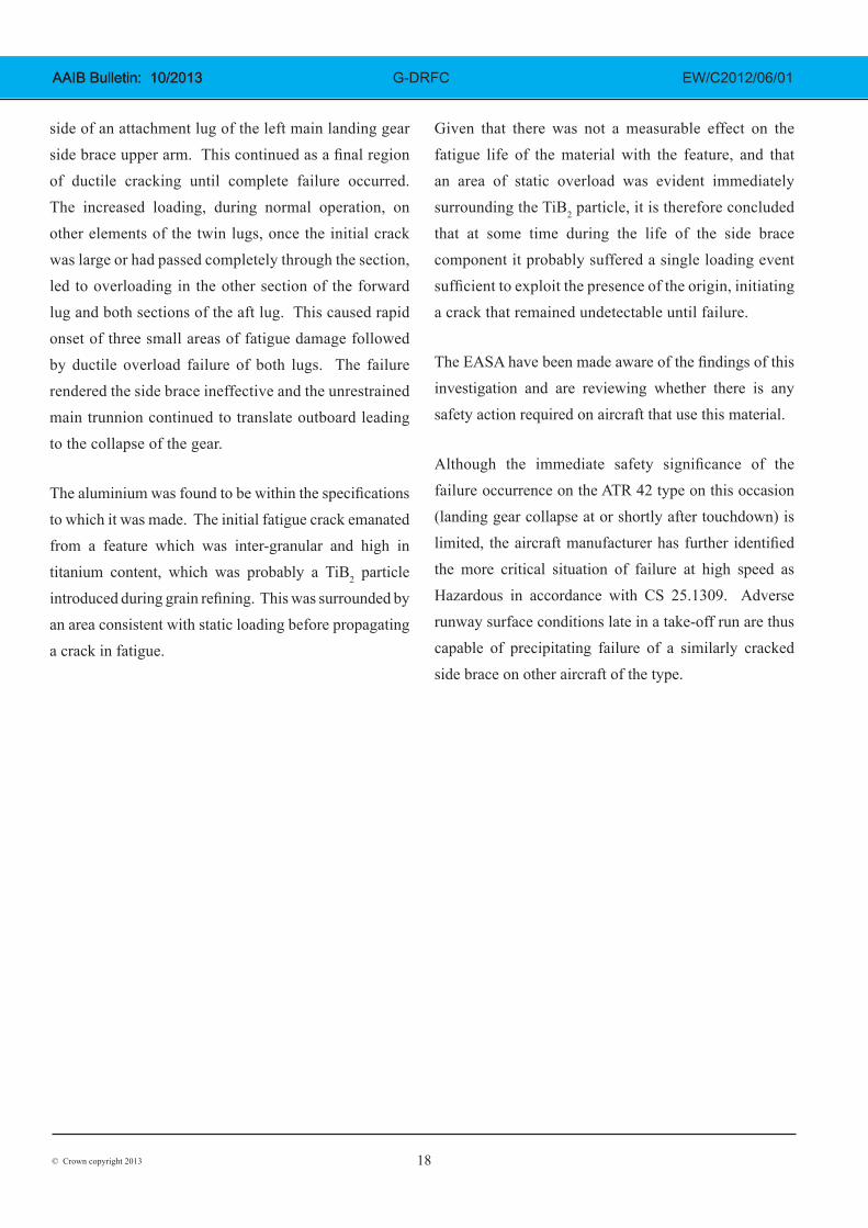
The general nature of the failure mechanism precipitating
the collapse of the landing gear is clear. A fatigue crack
propagated through most of the cross-section of one
18© Crown copyright 2013
AAIB Bulletin: 10/2013 AAIB Bulletin: 10/2013 G-DRFC EW/C2012/06/01
side of an attachment lug of the left main landing gear side brace upper arm. This continued as a final region of ductile cracking until complete failure occurred. The increased loading, during normal operation, on other elements of the twin lugs, once the initial crack was large or had passed completely through the section, led to overloading in the other section of the forward lug and both sections of the aft lug. This caused rapid onset of three small areas of fatigue damage followed by ductile overload failure of both lugs. The failure rendered the side brace ineffective and the unrestrained main trunnion continued to translate outboard leading to the collapse of the gear.
The aluminium was found to be within the specifications to which it was made. The initial fatigue crack emanated from a feature which was inter-granular and high in titanium content, which was probably a TiB2 particle introduced during grain refining. This was surrounded by an area consistent with static loading before propagating a crack in fatigue.
Given that there was not a measurable effect on the fatigue life of the material with the feature, and that an area of static overload was evident immediately surrounding the TiB2 particle, it is therefore concluded that at some time during the life of the side brace component it probably suffered a single loading event sufficient to exploit the presence of the origin, initiating a crack that remained undetectable until failure.
The EASA have been made aware of the findings of this investigation and are reviewing whether there is any safety action required on aircraft that use this material.
Although the immediate safety significance of the failure occurrence on the ATR 42 type on this occasion (landing gear collapse at or shortly after touchdown) is limited, the aircraft manufacturer has further identified the more critical situation of failure at high speed as Hazardous in accordance with CS 25.1309. Adverse runway surface conditions late in a take-off run are thus capable of precipitating failure of a similarly cracked side brace on other aircraft of the type.