Embed Size (px)
Citation preview
Issue Date
August 2013
INSTALLATION
INSTRUCTIONS
Accessory Application Publication No.
MII 14607
© 2013 Honda Motor Co., Ltd. - All Rights Reserved.
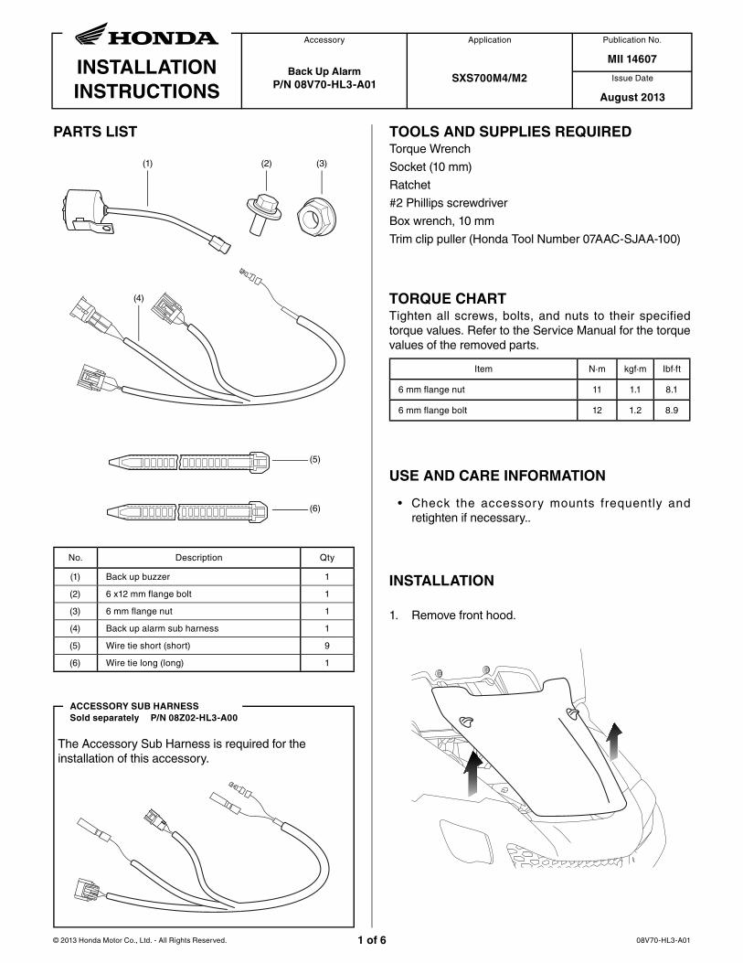
PARTS LIST
08V70-HL3-A011 of 6
Back Up Alarm
P/N 08V70-HL3-A01SXS700M4/M2
No. Description Qty
(1) Back up buzzer 1
(2) 6 x12 mm flange bolt 1
(3) 6 mm flange nut 1
(4) Back up alarm sub harness 1
(5) Wire tie short (short) 9
(6) Wire tie long (long) 1
TORQUE CHARTTighten all screws, bolts, and nuts to their specified torque values. Refer to the Service Manual for the torque values of the removed parts.
Item N·m kgf·m Ibf·ft
6 mm flange nut 11 1.1 8.1
6 mm flange bolt 12 1.2 8.9
USE AND CARE INFORMATION
• Check the accessory mounts frequently and retighten if necessary..
TOOLS AND SUPPLIES REQUIREDTorque Wrench
Socket (10 mm)
Ratchet
#2 Phillips screwdriver
Box wrench, 10 mm
Trim clip puller (Honda Tool Number 07AAC-SJAA-100)
INSTALLATION
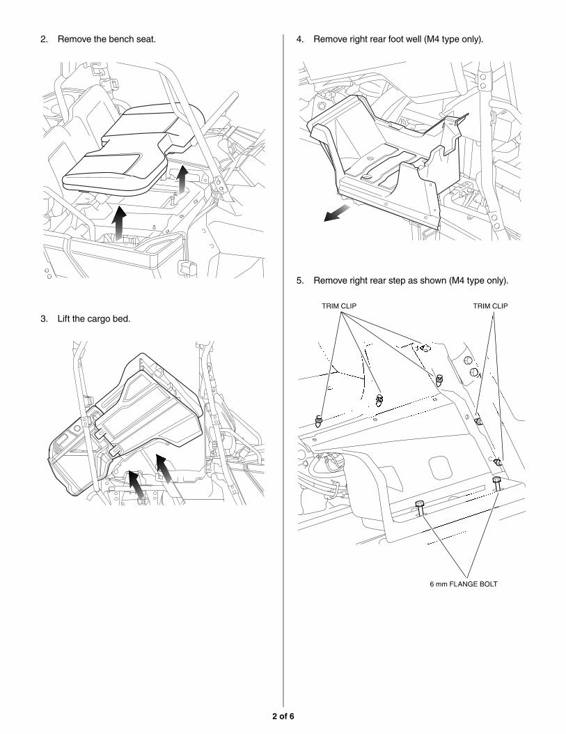
1. Remove front hood.
(1) (2) (3)
(4)
(5)
(6)
The Accessory Sub Harness is required for the installation of this accessory.
ACCESSORY SUB HARNESS
Sold separately P/N 08Z02-HL3-A00
2 of 6
3. Lift the cargo bed.
4. Remove right rear foot well (M4 type only).2. Remove the bench seat.
5. Remove right rear step as shown (M4 type only).
TRIM CLIP TRIM CLIP
6 mm FLANGE BOLT
3 of 6
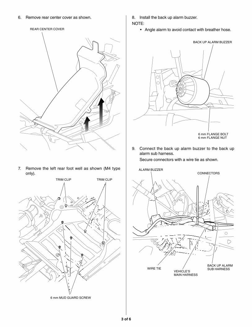
6. Remove rear center cover as shown.
REAR CENTER COVER
8. Install the back up alarm buzzer.
NOTE:
• Angle alarm to avoid contact with breather hose.
7. Remove the left rear foot well as shown (M4 type only).
TRIM CLIP TRIM CLIP
6 mm MUD GUARD SCREW
9. Connect the back up alarm buzzer to the back up alarm sub harness.
Secure connectors with a wire tie as shown.
BACK UP ALARM BUZZER
CONNECTORS
WIRE TIEVEHICLE’SMAIN HARNESS
6 mm FLANGE BOLT6 mm FLANGE NUT
ALARM BUZZER
BACK UP ALARMSUB HARNESS
4 of 6
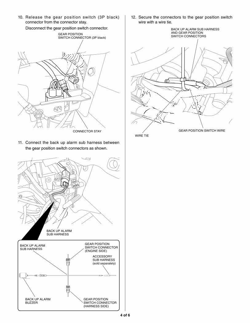
10. Release the gear position switch (3P black) connector from the connector stay.
Disconnect the gear position switch connector.
12. Secure the connectors to the gear position switch wire with a wire tie.
BACK UP ALARM SUB HARNESS AND GEAR POSITIONSWITCH CONNECTORS
WIRE TIE
GEAR POSITION SWITCH WIRE
GEAR POSITIONSWITCH CONNECTOR (3P black)
CONNECTOR STAY
BACK UP ALARMSUB HARNESS
GEAR POSITIONSWITCH CONNECTOR(ENGINE SIDE)
GEAR POSITIONSWITCH CONNECTOR(HARNESS SIDE)
BACK UP ALARMSUB HARNESS
BACK UP ALARMBUZZER
ACCESSORY SUB HARNESS(sold separately)p
11. Connect the back up alarm sub harness between the gear position switch connectors as shown.
5 of 6
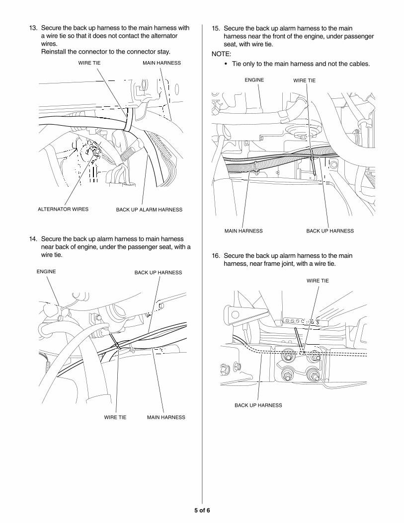
14. Secure the back up alarm harness to main harness near back of engine, under the passenger seat, with a wire tie.
15. Secure the back up alarm harness to the main harness near the front of the engine, under passenger seat, with wire tie.
NOTE:
• Tie only to the main harness and not the cables.
16. Secure the back up alarm harness to the main harness, near frame joint, with a wire tie.
BACK UP HARNESS
WIRE TIE MAIN HARNESS
WIRE TIE
MAIN HARNESS BACK UP HARNESS
WIRE TIE
BACK UP HARNESS
13. Secure the back up harness to the main harness with a wire tie so that it does not contact the alternator wires.Reinstall the connector to the connector stay.
WIRE TIE MAIN HARNESS
ALTERNATOR WIRES BACK UP ALARM HARNESS
ENGINE
ENGINE
6 of 6
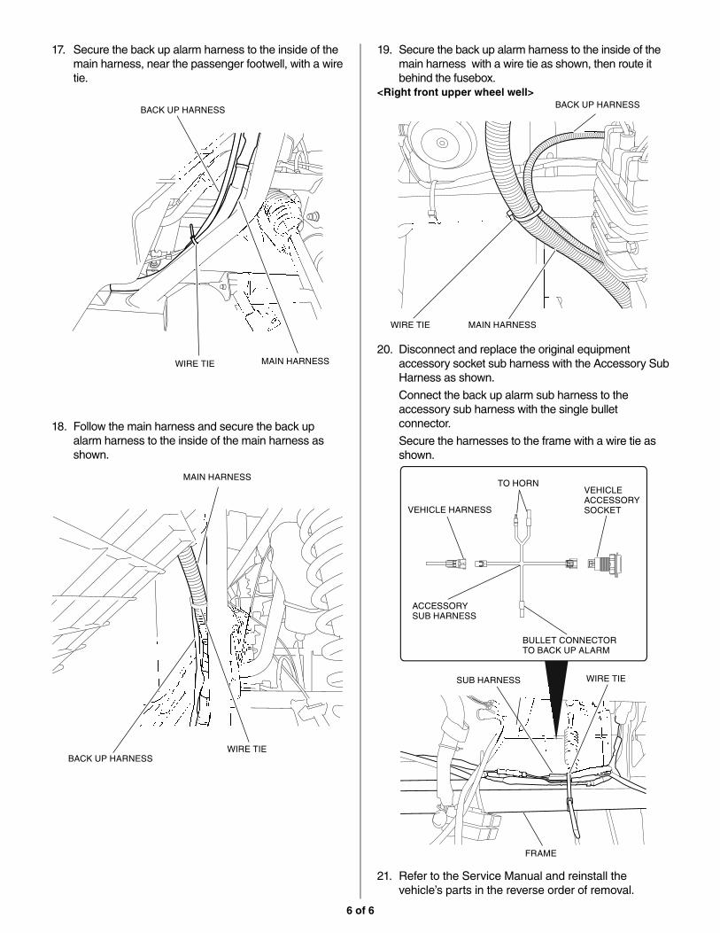
18. Follow the main harness and secure the back up alarm harness to the inside of the main harness as shown.
19. Secure the back up alarm harness to the inside of the main harness with a wire tie as shown, then route it behind the fusebox.
20. Disconnect and replace the original equipment accessory socket sub harness with the Accessory Sub Harness as shown.
Connect the back up alarm sub harness to the accessory sub harness with the single bullet connector.
Secure the harnesses to the frame with a wire tie as shown.
MAIN HARNESS
BACK UP HARNESSWIRE TIE
WIRE TIESUB HARNESS
FRAME
17. Secure the back up alarm harness to the inside of the main harness, near the passenger footwell, with a wire tie.
BACK UP HARNESS
WIRE TIE MAIN HARNESS
BACK UP HARNESS
WIRE TIE MAIN HARNESS
<Right front upper wheel well>
TO HORN
VEHICLE HARNESS
VEHICLE ACCESSORY SOCKET
BULLET CONNECTORTO BACK UP ALARM
ACCESSORYSUB HARNESS
21. Refer to the Service Manual and reinstall the vehicle’s parts in the reverse order of removal.


![HL3 Series Insert Manual...with 2 side shields 0 30 30 6 92 20 ft. from burner 0 11 11 6 44 HL3 (50, 60, 70) - 200 [N, P] 0 41 41 6 94 45 63 8 10 94 with 1 side shield 0 54 8 6 94](https://img.pdfslide.us/doc/110x75/5f0527c57e708231d4118be7/hl3-series-insert-manual-with-2-side-shields-0-30-30-6-92-20-ft-from-burner.jpg)


![cans.ubclss.comcans.ubclss.com/.../cans/...Winter_2014_Lucy_Yuan.docx · Web viewA. Representations and Terms2. Heilbut, Symons & Co v Buckleton [1913] HL3. Leaf v International](https://img.pdfslide.us/doc/110x75/5ea11b4a8cba9f44f01f5119/cans-web-view-a-representations-and-terms2-heilbut-symons-co-v-buckleton.jpg)