Embed Size (px)
Citation preview

OfficeConnect OC20 Access PointInstallation Guide
The OfficeConnect OC20 wireless access points (APs) support IEEE802.11ac standards for high-performance WLAN, and are equipped with two radios. Multiple-in, Multiple-output (MIMO) technology allows these APs to deliver high-performance 802.11n 2.4 GHz and 802.11ac 5 GHz functionality, while also supporting 802.11a/b/g wireless services.
The OC20 access points provide the following capabilities:
Wireless transceiver IEEE 802.11a/b/g/n/ac operation as a wireless access point
or air monitor Compatibility with IEEE 802.3af PoE Centralized management configuration and upgrade Integrated Bluetooth Low Energy (BLE) Radio
Package Contents OC20 access point Ceiling Rail Adapter (spare: AP-220-MNT-C1) AP-220-MNT-W1W Quick Start Guide
!
This device must be professionally installed and serviced by a trained ACMP or similar HPE-certified technician. HPE access points are classified as radio transmission devices, and are subject to government regulations of the host country. The network administrator(s) is/are responsible for ensuring that configuration and operation of this equipment is in compliance with their country’s regulations. For complete list of approved channels in your country, refer to the refer to the ArubaOS Downloadable Regulatory Table Release Notes at http://h20565.www2.hpe.com/hpsc/doc/public/display?docId=a00026718en_us.
Inform your supplier if there are any incorrect, missing, or damaged parts. If possible, retain the carton, including the original packing materials. Use these materials to repack and return the unit to the supplier if needed.
Rev 06 | March 2018
Software
OC20 Hardware OverviewFigure 1 Front
LEDs
The OC20 access points have two LEDs that indicate the system and radio status of the device. These two LEDs can be configured into three separate modes:
Normal mode (by default): See Table 1 Both LEDs off Blink mode: Both LEDs blink green (synchronized)
!Access points are radio transmission devices and are subject to governmental regulation. Network administrators responsible for the configuration and operation of access points must comply with local broadcast regulations. Specifically, access points must use channel assignments appropriate to the location in which the access point will be used.
Table 1 OC20 LEDs Status in Normal Mode
LED Color/State Meaning
System Status(Left)
Off Device powered off
Green- Blinking
Device booting, not ready for use
Green- Solid Device ready for use, no restrictions
Green- Flashing
Device ready for use, uplink negotiated in sub optimal speed (<1Gbps)
Red- Solid System error condition
Radio Status(Right)
Off Device powered off, or both radios disabled
Green- Solid Both radios enabled in access mode
Green- Blinking
One radio enabled in access mode
Amber- Solid Both radios enabled in monitor mode
Amber- Blinking
One radio enabled in monitor mode
Alternating Green: one radio in access mode Amber: one radio in monitor mode
System Status
Radio Status
1

Figure 2 Back Panel
Console Port
The serial console port is located at the back of the OC20 and is a 4-pin connector covered by a dust cover. An optional serial adapter cable (AP-CBL-SER) is sold separately to connect the AP to a serial terminal or a laptop for direct local management.
Ethernet Port
The OC20 access points are equipped with one 10/100/1000Base-T (RJ-45) auto-sensing, MDI/MDX Ethernet port (ENET0) for wired network connectivity. This port supports IEEE 802.3af Power over Ethernet (PoE), as a standard defined Powered Device (PD) from a Power Sourcing Equipment (PSE) such as a PoE midspan injector or network infrastructure that supports PoE.
Kensington Lock Slot
The OC20 access points are equipped with a Kensington lock slot for additional security.
Reset Button
To reset a OC20 access point to factory default settings:
1. Press and hold down the reset button using a small, narrow object such as a paper clip while the OC20 access point is not powered on (either via DC power or PoE.)
2. Connect the power supply (DC or PoE) to the OC20 access point while the reset button is being held down.
3. Release the reset button on the OC20 access point after 15 seconds.
DC Power Socket
If PoE is not available, an optional AP-AC-12V30B power adapter kit (sold separately) can be used to power the OC20 access points.
Additionally, a locally-sourced AC-to-DC adapter (or any DC source) can be used to power this device, as long as it complies with all applicable local regulatory requirements and the DC interface meets the following specifications:
12 Vdc (+/- 5%) and at least 12W Center-positive 2.1/5.5 mm circular plug, 9.5 mm length
Before You Begin
Pre-Installation Checklist
Before installing your OC20 access points, ensure that you have the following:
Cat5E or better UTP cable of required length One of the following power sources:
IEEE 802.3af-compliant Power over Ethernet (PoE) source.
HPE Aruba AP-AC-12V30B power adapter kit (sold separately)
Identifying Specific Installation LocationsYou can mount the OC20 access point on the ceiling or a wall. Use your RF plan or wireless deployment modeling tools to determine the proper installation location(s). Each location should be as close as possible to the center of the intended coverage area and should be free from obstructions or obvious sources of interference. These RF absorbers/reflectors/interference sources will impact RF propagation and should have been accounted for during the planning phase and adjusted for in your RF plan.
Identifying Known RF Absorbers, Reflectors and Interference SourcesIdentifying known RF absorbers, reflectors, and interference sources while in the field during the installation phase is critical. Make sure that these sources are taken into consideration when you attach an access point to its fixed location. Examples of sources that degrade RF performance include:
Cement and brick Objects that contain water Metal Microwave ovens Wireless phones and headsets
CONSOLEENET
12V 1A
350mA57V
Console Port
Ethernet Port DC Power Socket
Reset Button
Kensington Lock Slot
!FCC Statement: Improper termination of access points installed in the United States configured to non-US model controllers will be in violation of the FCC grant of equipment authorization. Any such willful or intentional violation may result in a requirement by the FCC for immediate termination of operation and may be subject to forfeiture (47 CFR 1.80).
!
EU Statement: Lower power radio LAN product operating in 2.4 GHz and 5 GHz bands. Produit radio basse puissance pour réseau local opérant sur les fréquences 2,4 GHz et 5 GHz. Niedrigenergie-Funk-LAN-Produkt, das im 2,4-GHz- und im 5-GHz-Band arbeitet. Apparati Radio LAN a bassa Potenza, operanti a 2.4 GHz e 5 GHz.
2 OfficeConnect OC20 Access Point | Installation Guide

Installing the Access Point
The OC20 access point ships with a ceiling rail adapter and an AP-220-MNT-W1W mount bracket. Additional ceiling or wall mount kits are sold separately as accessories.
Using the Ceiling Rail Adapter
The included ceiling rail adapter can be used to attach the OC20 access point to a 9/16” or 15/16” ceiling rail.
1. Pull the necessary cables through a prepared hole in the ceiling tile near where the access point will be placed.
2. Place the adapter against the back of the access point with the adapter at an angle of approximately 30 degrees to the tabs (see Figure 3).
3. Twist the adapter clockwise until it snaps into place in the tabs (see Figure 3).
Figure 3 Attaching the Ceiling Rail Adapter to the AP
4. Hold the access point next to the ceiling tile rail with the mounting slots at approximately a 30-degree angle to the ceiling tile rail (see Figure 4 and Figure 5). Make sure that any cable slack is above the ceiling tile.
5. Pushing toward the ceiling tile, rotate the access point clockwise until the device clicks into place on the ceiling tile rail.
Figure 4 Mounting the Access Point to a 15/16” ceiling rail
Figure 5 Mounting the Access Point to a 9/16” ceiling rail
Using the AP-220-MNT-W1W Bracket
The included AP-220-MNT-W1W bracket can be used to mount the OC20 access point to a wall.
1. Begin by attaching the bracket to the wall as shown in Figure 6 or Figure 7.
a. Install any necessary wall anchors. Wall anchors are not included in the package.
b. Align the screw holes in the bracket with the previously installed anchors or demarcated screw points.
c. Insert the screws to secure the bracket. Screws are not included in the package.
Figure 6 Attaching the Bracket to a Wall
Figure 7 Attaching the Bracket to a Wall (Alternate)
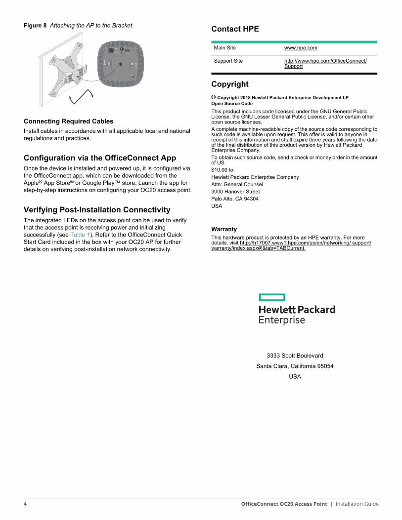
2. Attach the AP to the secured bracket as shown in Figure 8.
a. Align the AP with the bracket, placing the AP so that its mounting tabs are at an angle of approximately 30 degrees to the bracket.
3. Pushing toward the wall, rotate the AP clockwise until it clicks into place (see Figure 8).
Service to all Hewlett Packard Enterprise access points should be performed by an AMCP certified technician or similar.
!The installer is responsible for securing the access point onto the ceiling tile rail in accordance with the steps below. Failure to properly install this product may result in physical injury and/or damage to property.
AP-130_003
AP-130_006
3 OfficeConnect OC20 Access Point | Installation Guide
Contact HPE
Copyright
© Copyright 2018 Hewlett Packard Enterprise Development LPOpen Source Code
This product includes code licensed under the GNU General Public License, the GNU Lesser General Public License, and/or certain other open source licenses.A complete machine-readable copy of the source code corresponding to such code is available upon request. This offer is valid to anyone in receipt of this information and shall expire three years following the date of the final distribution of this product version by Hewlett Packard Enterprise Company.To obtain such source code, send a check or money order in the amount of US$10.00 to:Hewlett Packard Enterprise CompanyAttn: General Counsel3000 Hanover StreetPalo Alto, CA 94304USA
WarrantyThis hardware product is protected by an HPE warranty. For more details, visit http://h17007.www1.hpe.com/us/en/networking/ support/warranty/index.aspx#!&tab=TABCurrent.
3333 Scott Boulevard
Santa Clara, California 95054
USA
Main Site www.hpe.com
Support Site http://www.hpe.com/OfficeConnect/Support
Figure 8 Attaching the AP to the Bracket
Connecting Required Cables
Install cables in accordance with all applicable local and national regulations and practices.
Configuration via the OfficeConnect AppOnce the device is installed and powered up, it is configured via the OfficeConnect app, which can be downloaded from the Apple® App Store® or Google Play™ store. Launch the app for step-by-step instructions on configuring your OC20 access point.
Verifying Post-Installation ConnectivityThe integrated LEDs on the access point can be used to verify that the access point is receiving power and initializing successfully (see Table 1). Refer to the OfficeConnect Quick Start Card included in the box with your OC20 AP for further details on verifying post-installation network connectivity.
4 OfficeConnect OC20 Access Point | Installation Guide