Embed Size (px)
Citation preview

Cisco SeOL-21122-01
C H A P T E R 9
Access Layer Security DesignOne of the most vulnerable points of the network is the access edge. The access layer is where end users connect to the network. In the past, network administrators have largely relied on physical security to protect this part of the network. Unauthorized users were not allowed to enter a secure building where they could plug into the network, and students didn't carry computers with them. Today, contractors and consultants regularly have access to secure areas, and a student carrying a laptop is unsurprising. Once inside, there is nothing to prevent a contractor or student from plugging into a wall jack and gaining access to the corporate network. There is no need to enter an employee office to do this. Conference rooms frequently offer network access through wall jacks or even desktop switches. Once connected to the network, everyone (employees, contractors, consultants, guests, students, and malicious users) has access to all the resources on the network.
What is commonly called the access layer in network design is the business end of the network, the part of the network that your users see and interact with. The end users do not see or appreciate the power of your collapsed core distribution layer, the elegance of your addressing plans, or the genius of your end to end network design. Your more technical users may be able to identify an RJ-45 port or WLAN access point if asked, but most users simply expect the network to be there. Training users on using the access is focused upon small—the smaller the better—number of steps users must go through to gain access to their network applications.
At the same time as providing simple uncomplicated network access for users, the access layer provides the first line of security defense for the network, provide service differentiation based upon management policies and, providing power to support the deployment of specialized devices.
The roles can be broken broadly into the following areas:
• Access layer security
• Access layer QoS
• Access layer Power-over-Ethernet (PoE)
Access Layer SecurityThe access layer is where your client’s network devices directly connect to your network. You want their connection to be as efficient, simple, and secure as possible. This involves controlling who accesses the network and for what services. Controlling access may be as simple as blocking access, or it may involve a redirection or quarantining action.
To continue the general security metaphor part of controlling the boundary is also observing inappropriate behavior at the boundary can also result in blocked access.
9-1rvice Ready Architecture for Schools Design Guide

Chapter 9 Access Layer Security Design Access Layer Security
The Schools SRA uses the native Cisco switch features and Cisco security products to provide boundary control services. The primary tools for access layer security in the schools are as follows:
• Catalyst Integrated Security Features (CISF)
• Cisco Clean Access (NAC)
• Cisco Identity-Based Network Networking Services (IBNS)
When implementing the security features, consideration needs to be made upon the client requirements using the access layer. In the Schools SRA, the following client connections are considered:
• Ethernet PC client ports
• Printer ports
• IP phone ports
• Wireless clients
• AP ports
• Access layer PoE
• Access layer QoS
Catalyst Integrated Security Features (CISF) Protected PortsCatalyst Integrated Security Features (CISF) includes private VLANs, port security, DHCP snooping, IPSource Guard, secure Address Resolution Protocol (ARP) detection, and dynamic ARP inspection. These features protect the network against attacks such as man-in-the-middle, spoofing, and infrastructure denial-of-service (DoS) attacks.
• Port Security—Where the number of MAC addresses allows on a switch port is monitored, and the switch can respond to violations with management messages and changes in the port state.
• DHCP snooping—Where DHCP messages are inspected, and filtered to ensure that DHCP server messages only come from a trusted interface.
• IPSource Guard—Where the IP traffic is restricted based upon DHCP or static IP address MAC bindings to ensure a host doesn't attempt to use the IP address of a neighboring host
• Dynamic ARP inspection—Where the all ARP packets from untrusted interfaces are inspected to ensure that they contain valid MAC address and IP address pairings, preventing ARP spoofing attacks
• ARP rate limiting—Where an excessive rate of ARP request (which must be processed by network hosts CPUs), and the switch responds with access restriction if this rate is exceeded.
• Storm Control—Prevents traffic on a LAN from being disrupted by a broadcast, multicast, or unicast storm
CISF Port Configuration
switchport port-security maximum 2 switchport port-security switchport port-security aging time 2 switchport port-security violation restrict switchport port-security aging type inactivity ip arp inspection limit rate 100 ip dhcp snooping limit rate 100 storm-control broadcast level 20.00 10.00 storm-control multicast level 50.00 30.00
9-2Cisco Service Ready Architecture for Schools Design Guide
OL-21122-01

Chapter 9 Access Layer Security Design Access Layer Security
NAC Protected PortsThis section discusses he Cisco NAC Appliance (also known as Cisco Clean Access) in the Schools SRA. It is not intended to be a comprehensive guide on the Cisco NAC Appliance solution itself. This chapter focuses on general NAC Appliance design principles and how they apply to components of the Schools SRA.
Cisco NAC Appliance is an easily deployed NAC product that uses the network infrastructure to enforce security policy compliance on all devices seeking to access network computing resources. With Cisco NAC Appliance, network administrators can authenticate, authorize, evaluate, and remediate wired, wireless, and remote users and their machines prior to network access. The Cisco NAC Appliance identifies whether networked devices such as laptops, or IP phones are compliant with network security policies, and repairs any vulnerabilities before permitting access to the network.
When deployed, the Cisco NAC Appliance provides the following benefits:
• Recognizes users, their devices, and their roles in the network. This first step occurs at the point of authentication, before malicious code can cause damage.
• Evaluates whether machines are compliant with security policies. Security policies can include specific anti-virus or anti-spyware software, OS updates, or patches. Cisco NAC Appliance supports policies that vary by user type, device type, or operating system.
• Enforces security policies by blocking, isolating, and repairing non-compliant machines.
• Non-compliant machines are redirected to a quarantine network, where remediation occurs at the discretion of the administrator.
Figure 9-1 shows the following four key functions of the NAC:
• Authenticate and authorize
• Scan and evaluate
• Quarantine and enforce
• Update and remediate
Figure 9-1 The Four Functions of the NAC Framework
Authenticate and Authorize
• Enforces authorizationpolicies and privilges
• Supports multiple user roles
Quarantine and Enforce
• Isolate non-compliant devicesfrom rest of network
• MAC and IP-based quarantineeffective at a per-user level
Scan and Evaluate
• Agent scan for required versionsof hotfixes, AV, etc.
• Network scan for virus and worm infections and port vulnerbilities
Update and Remediate
• Network-based tools forvulnerbility and threatremediation
• Help-desk integration
2274
97
9-3Cisco Service Ready Architecture for Schools Design Guide
OL-21122-01

Chapter 9 Access Layer Security Design Access Layer Security
For a more in-depth overview of the Clean Access Server and Clean Access Manager, see the following URLs:
• Cisco NAC Appliance-Clean Access Server Installation and Administration Guide http://www.cisco.com/application/pdf/en/us/guest/products/ps7122/c1626/ccmigration_09186a00807a4090.pdf
• Cisco NAC Appliance-Clean Access Manager Installation and Administration Guide http://www.cisco.com/en/US/docs/security/nac/appliance/configuration_guide/45/cam/45cam-book.html
Cisco Clean Access Components
Cisco NAC Appliance is a network-centric integrated solution administered from the Cisco Clean Access Manager web console and enforced through the Clean Access Server and (optionally) the Clean Access Agent or Cisco NAC Web Agent. Cisco NAC Appliance checks client systems, enforces network requirements, distributes patches and antivirus software, and quarantines vulnerable or infected clients for remediation before clients access the network. Cisco NAC Appliance consists of the components shown in Figure 9-2.
Figure 9-2 NAC Components (Source Document NAC CAM Configuration Guide)
Clean AccessServer (CAS)
Authentication sources(LDAP, RADIUS, Kerberos,
WindowsNT)
DNSserver
Clean AccessManager (CAM)
Firewall
2274
98PCs with
Clean Access Agent (CAA)
SwitchL2
RouterL3
Internet
eth1 eth0
Admin laptop
Clean Access ManagerWeb admin console
LAN/Intranet
9-4Cisco Service Ready Architecture for Schools Design Guide
OL-21122-01

Chapter 9 Access Layer Security Design Access Layer Security
Clean Access Manager (CAM)
CAM is the administration server for Clean Access deployment. The secure web console of the Clean Access Manager is the single point of management for up to 20 Clean Access Servers in a deployment (or 40 CASs if installing a SuperCAM). For Out-of-Band (OOB) deployment, the web admin console allows you to control switches and VLAN assignment of user ports through the use of SNMP. In the Schools SRA, the CAM would be located at the district office.
Clean Access Server (CAS)
CAS is the enforcement server between the untrusted (managed) network and the trusted network. The CAS enforces the policies you have defined in the CAM web admin console, including network access privileges, authentication requirements, bandwidth restrictions, and Clean Access system requirements. You can install a CAS as either a standalone appliance (like the Cisco NAC-3300 Series) or as a network module (Cisco NME-NAC-K9) in a Cisco ISR chassis and deploy it in-band (always inline with user traffic) or OOB (inline with user traffic only during authentication/posture assessment).
The CAS can also be deployed in Layer 2 mode (users are Layer-2-adjacent to CAS) or Layer 3 mode (users are multiple Layer-3 hops away from the CAS). You can also deploy several CASs of varying size/capacity to fit the needs of varying network segments. You can install Cisco NAC-3300 Series appliances in your company headquarters core, for example to handle thousands of users and simultaneously install one or more Cisco NAC network modules in ISR platforms to accommodate smaller groups of users at a satellite office, for example.
In the Schools SRA, the CAS would be located at the schools sites and the district office, and it would be used to provide Layer-2 or Layer-3 OOB authentication/posture assessment.
Clean Access Agent (CAA)
CAA is optional read-only agent that resides on Windows clients. It checks applications, files, services, or registry keys to ensure that clients meets your specified network and software requirements prior to gaining access to the network.
Note There is no client firewall restriction with CAA posture assessment. The agent can check the client registry, services, and applications even if a personal firewall is installed and running.
If NAC is implemented as part of the Schools SRA it is recommended that the CAA be used.
Cisco NAC Web Agent
The Cisco NAC Web Agent provides temporal posture assessment for client machines. Users launch the Cisco NAC Web Agent executable, which installs the Web Agent files in a temporary directory on the client machine via ActiveX control or Java applet. When the user terminates the Web Agent session, the Web Agent logs the user off of the network and their user ID disappears from the Online Users list.
Clean Access Policy Updates
Regular updates of prepackaged policies/rules that can be used to check the up-to-date status of operating systems, antivirus (AV), antispyware (AS), and other client software. Provides built-in support for 24 AV vendors and 17 AS vendors.
9-5Cisco Service Ready Architecture for Schools Design Guide
OL-21122-01

Chapter 9 Access Layer Security Design Access Layer Security
NAC Appliance Modes and Positioning
NAC Appliance allows multiple deployment options and may be placed at different points in the network. The modes of operation can be generally defined as follows:
• Out-of-band (OOB) virtual gateway
• OOB IP gateway
• In-band (IB) virtual gateway
• IB real IP gateway
OOB Modes
OOB deployments require user traffic to traverse through the NAC Appliance only during authentication, posture assessment, and remediation. When a user is authenticated and passes all policy checks, their traffic is switched normally through the network and bypasses the appliance. See Figure 9-3.
Figure 9-3 Layer-2 OOB Topology
To deploy the NAC Appliance in this manner, the client device must be directly connected to the network via a Catalyst switch port. After the user is authenticated and passes posture assessment, the Clean Access Manager (CAM) instructs the switch to map the user port from an unauthenticated VLAN (which switches or routes user traffic to the NAC) to an authenticated (authorized) VLAN that offers full access privileges. For example, as shown in Figure 9-3, the client PC is connected through VLAN 110 to the NAC Clean Access Server for the authentication and posture assessment, and is moved to VLAN 10 once it successfully completes the authentication and authorize, and scan and evaluation phases of the NAC framework.
In-Band Modes
When the NAC Appliance is deployed in-band, all user traffic, both unauthenticated and authenticated, passes through the NAC Appliance, which may be positioned logically or physically between end users and the network(s) being protected. See Figure 9-4 for a logical in-band topology example and Figure 9-5 for a physical in-band topology example.
MGR
VLAN 900
802.1q TrunkVLANs 110 and 10
VLAN 10Authenticated
Network Access
VLAN 10
VLAN 110Authentication andPosture Assessment
VLAN 10
VLAN 110
2212
97
9-6Cisco Service Ready Architecture for Schools Design Guide
OL-21122-01

Chapter 9 Access Layer Security Design Access Layer Security
Figure 9-4 In-Band Virtual Gateway Topology
Figure 9-5 Physical In-Band Topology
In-Band Virtual Gateway
When the NAC Appliance is configured as a virtual gateway, it acts as a bridge between end users and the default gateway (router) for the client subnet being managed. The following two bridging options are supported by the NAC Appliance:
• Transparent—For a given client VLAN, the NAC Appliance bridges traffic from its untrusted interface to its trusted interface. Because the appliance is aware of “upper layer protocols”, by default it blocks all traffic except for Bridge Protocol Data Unit (BPDU) frames (spanning tree) and
MGR
VLAN 900
VLAN 110
VLAN 10
VLAN 110
Posture AssessmentAuthenticated Access
VLAN 10
VLAN 110
2212
98MGR
VLAN 900
VLAN 10
VLAN 110
Posture AssessmentAuthenticated Access
VLAN 10
2212
99
9-7Cisco Service Ready Architecture for Schools Design Guide
OL-21122-01

Chapter 9 Access Layer Security Design Access Layer Security
those protocols explicitly permitted in the “unauthorized” role; for example, DNS and DHCP. In other words, it permits those protocols that are necessary for a client to connect to the network, authenticate, undergo posture assessment, and remediation. This option is viable when the NAC Appliance is positioned physically in-band between end users and the upstream network(s) being protected, as shown in Figure 5.
• VLAN mapping—This is similar in behavior to the transparent method except that rather than bridging the same VLAN from the untrusted side to the trusted side of the appliance, two VLANs are used. For example, Client VLAN 131 is defined for the untrusted interface of the NAC Appliance. There is no routed interface or switched virtual interface (SVI) associated with VLAN 131. VLAN 31 is configured between the trusted interface of the NAC Appliance and the next-hop router interface/SVI for the client subnet. A mapping rule is made in the NAC Appliance that forwards packets arriving on VLAN 131 and forwards them out VLAN 31 by swapping VLAN tag information. The process is reversed for packets returning to the client. Note that in this mode, BPDUs are not passed from the untrusted-side VLANs to their trusted-side counterparts.
The VLAN mapping option is usually selected when the NAC Appliance is positioned logically in-band between clients and the networks being protected. This is the bridging option that should be used if the NAC Appliance is going to be deployed in the virtual gateway mode.
In-Band Real IP Gateway
When the NAC Appliance is configured as a “real” IP gateway, it behaves like a router and forwards packets between its interfaces. In this scenario, one or more client VLAN/subnets reside behind the untrusted interface. The NAC Appliance acts as a default gateway for all clients residing on those networks. Conversely, a single VLAN/subnet is defined on the trusted interface, which represents the path to the protected upstream network(s).
After successful client authentication and posture assessment, the NAC Appliance by default routes traffic from the untrusted networks to the trusted interface, where it is then forwarded based on the routing topology of the network.
The NAC Appliance is not currently able to support dynamic routing protocols. As such, static routes must be configured within the trusted side of the Layer 3 network for each client subnet terminating on or residing behind the untrusted interface. These static routes should reference, as a next hop, the IP address of the trusted interface of the NAC.
If one or more Layer-3 hops exist between the untrusted NAC interface and the end-client subnets, static routes to the client networks must be configured in the NAC Appliance. Likewise, a static default route (0/0) is required within the downstream Layer 3 network (referencing the IP address of the untrusted NAC interface) to facilitate default routing behavior from the client networks to the NAC Appliance.
Depending on the topology, multiple options exist to facilitate routing to and from the NAC Appliance, including static routes, VRF-Lite, MPLS VPN, and other segmentation techniques. It is beyond the scope of this design guide to examine all possible methods.
In-Band Versus Out-of-Band
Table 9-1 summarizes different characteristics of each type of deployment.
9-8Cisco Service Ready Architecture for Schools Design Guide
OL-21122-01
Chapter 9 Access Layer Security Design Access Layer Security
Out-of-Band Requirements
OOB implementation of Cisco NAC Appliance requires the switches and Wireless LAN Controllers be supported by the Cisco NAC Appliance software. All the switches tested as part of the development of the Schools SRA, apart from the Cisco Catalyst 2975, are supported by the Cisco NAC OOB, and the Wireless LAN Controllers are also supported by the NAC Appliance software used in this design guide. If the Catalyst 2975 is to be used as an access switch with the Cisco NAC Appliance, the NAC solution must be an in-band solution.
Note To obtain the latest list of supported devices, check the latest version of the Cisco NAC Appliance-Clean Access Manager Installation and Administration Guide at the following URL: http://www.cisco.com/en/US/docs/security/nac/appliance/configuration_guide/45/cam/45cam-book.html
Out-Of-Band, Layer 2 and Layer 3
The proposed design for the Schools SRA is an OOB design, in order the highest possible performance and scalability for traffic that has passed through the authentication, posture assessment, and remediation stages of NAC. The Schools SRA offers two different access layer options, a Layer-2 access layer for smaller schools and a hybrid Layer-2/Layer-3 access layer for larger schools. This means that either a Layer-2 OOB solution or a Layer-3 OOB NAC solution may be deployed.
NAC Deployment in the Schools SRA The Schools SRA provides for a Cisco NAC Appliance solution at each site type, District Office, School Site 1, and School Site 2, with a CAM at the District Office, and a CAS at the District Office and Schools Sites. In each of the different site types the CAS is directly connected to the core/distribution.
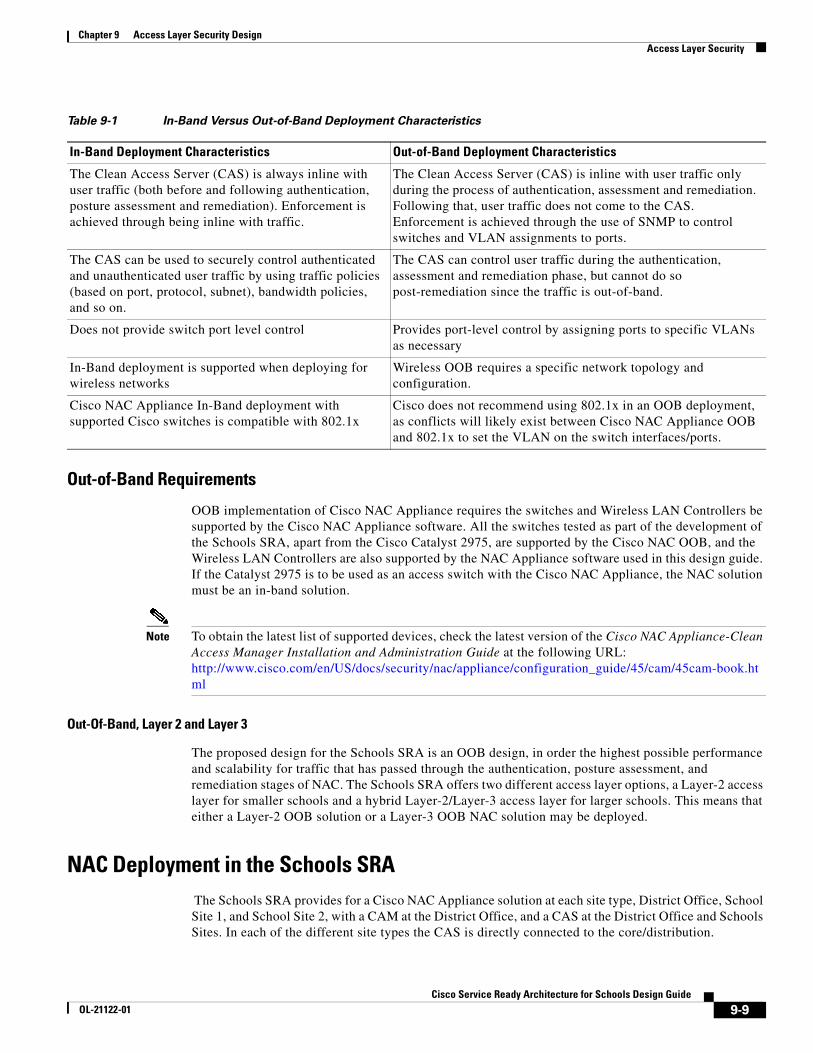
Table 9-1 In-Band Versus Out-of-Band Deployment Characteristics
In-Band Deployment Characteristics Out-of-Band Deployment Characteristics
The Clean Access Server (CAS) is always inline with user traffic (both before and following authentication, posture assessment and remediation). Enforcement is achieved through being inline with traffic.
The Clean Access Server (CAS) is inline with user traffic only during the process of authentication, assessment and remediation. Following that, user traffic does not come to the CAS. Enforcement is achieved through the use of SNMP to control switches and VLAN assignments to ports.
The CAS can be used to securely control authenticated and unauthenticated user traffic by using traffic policies (based on port, protocol, subnet), bandwidth policies, and so on.
The CAS can control user traffic during the authentication, assessment and remediation phase, but cannot do so post-remediation since the traffic is out-of-band.
Does not provide switch port level control Provides port-level control by assigning ports to specific VLANs as necessary
In-Band deployment is supported when deploying for wireless networks
Wireless OOB requires a specific network topology and configuration.
Cisco NAC Appliance In-Band deployment with supported Cisco switches is compatible with 802.1x
Cisco does not recommend using 802.1x in an OOB deployment, as conflicts will likely exist between Cisco NAC Appliance OOB and 802.1x to set the VLAN on the switch interfaces/ports.
9-9Cisco Service Ready Architecture for Schools Design Guide
OL-21122-01

Chapter 9 Access Layer Security Design Access Layer Security
The simple topology used in the Schools SRA sites means that a VLAN from an access layer to the untrusted interface of the NAC Appliance is always available as a standard component of the design, and untrusted traffic should never need to be tunneled to the CAS. This allows a common the network configuration, to support NAC at any of the School sites, regardless of whether the client devices are using a Layer-2 or Layer-3 access model. As the client can use a Layer-2 connection to the untrusted interface of the NAS in either Layer 2 or Layer 3 access mode (this requires a trunk between the Layer-3 access switch and the core/distribution. One VLAN of the trunk would carry the untrusted VLAN, and the other VLAN the IP routing for all other traffic), and the VLAN used once the client is trusted will be either be a Layer-2 access VLAN from the core/distribution switch or a Layer-3 access switch VLAN depending upon the site requirements.
This is illustrated in Figure 9-6 and Figure 9-7. In Figure 9-6, there is a simple Layer-2 NAC OOB connection where a client device upon initial connection to the network is given VLAN 264, which connects them directly to the untrusted interface of the NAS. The mapping of this interface through the NAC VLAN 64 trusted interface allows the client to obtain an IP address that belongs on VLAN 64. To perform any action permitted by an untrusted client, upon success completion of the NAC function, the access switch is instructed, via SNMP, to change the client VLAN to VLAN 64. Even though the client has changed Layer-2 VLANs its Layer-3 network connections are unchanged.
In Figure 9-7, the same processes are followed when the client is untrusted, but once the client has successfully completed its NAC functions the access switch is instructed via SNMP to change the client VLAN to VLAN 67—a subnet local to the access switch. As the Layer-3 information for the client has changed the switch is also instructed to “bounce” the client switch port to initiate a new DHCP request for an IP address appropriate to VLAN 67.
Figure 9-6 Layer 2 OOB topology
L2 UntrustedVLAN 264
L2 TrustedVLAN 64
2274
99
9-10Cisco Service Ready Architecture for Schools Design Guide
OL-21122-01

Chapter 9 Access Layer Security Design Access Layer Security
Figure 9-7 Layer 3 OOB Topology
Configuring the CAS and CAM The initial CAS and CAM configuration are done via directly on the server interface, and this is described in the installation guide, Cisco NAC Appliance Hardware Installation, Release 4.1. During the configuration stage the multiple steps must be followed in configuring the NAC Appliance with IP addresses, VLANs. passwords, etc. The installation guide contains worksheets assist in the gathering and preparation of this information for both the CAM and CAS.
Once the CAM(s) and CAS(s) are configured they can be configured by their web interfaces. Almost all of the NAC Appliance solution can be configured through the CAM, and it have be access via HTTPS to the IP address assigned during the appliance configuration stages.
The first task on the CAM before beginning configuration is the installation the licenses for the solution. A license must be installed for the CAM, and the CAS servers that the CAM control. The Cisco NAC Appliance Ordering Guide, provides information on the ordering options.
Licenses can be entered via the CAM web interface, as show in Figure 9-8.
L2 UntrustedVLAN 264
L2 TrustedVLAN 64
L3 TrustedVLAN 67
2275
00
9-11Cisco Service Ready Architecture for Schools Design Guide
OL-21122-01

Chapter 9 Access Layer Security Design Access Layer Security
Figure 9-8 NAC Appliance Licensing
Adding a CAS to the CAM
For a CAS server to be managed by the CAM, it must be added to the list of managed servers on the CAM. To do this the CAM needs to know the IP address of the CAS, and the Server Type (its role in the network) of the CAS. In addition to this the CAS and the CAM must have the same shared secret. The shared secret is configured during the server installation. An example of adding a CAS to the CAM, is shown in Figure 9-9.
9-12Cisco Service Ready Architecture for Schools Design Guide
OL-21122-01
Chapter 9 Access Layer Security Design Access Layer Security
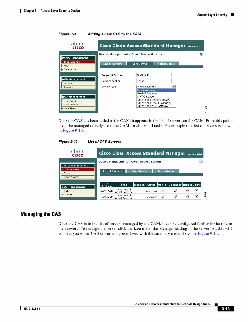
Figure 9-9 Adding a new CAS to the CAM
Once the CAS has been added to the CAM, it appears in the list of servers on the CAM. From this point, it can be managed directly from the CAM for almost all tasks. An example of a list of servers is shown in Figure 9-10.
Figure 9-10 List of CAS Servers
Managing the CAS
Once the CAS is in the list of servers managed by the CAM, it can be configured further for its role in the network. To manage the server click the icon under the Manage heading in the server list, this will connect you to the CAS server and present you with the summary menu shown in Figure 9-11.
9-13Cisco Service Ready Architecture for Schools Design Guide
OL-21122-01

Chapter 9 Access Layer Security Design Access Layer Security
Figure 9-11 CAS Management Menu
Under the CAS Network setting tab, shown in Figure 9-12. the basic network settings for the CAS can be seen and altered, if needed. In this example, we are keeping the network configuration performed during the server installation. The primary dialog under the Network Tab is the IP dialog, shown in Figure 9-12, the other dialogs allow the DHCP options to the configured—our example uses the default of DHCP passthrough— and the DNS options where host name, domain name, and DNS server information is added, as shown in Figure 9-13.
Figure 9-12 CAS Network Settings
9-14Cisco Service Ready Architecture for Schools Design Guide
OL-21122-01
Chapter 9 Access Layer Security Design Access Layer Security
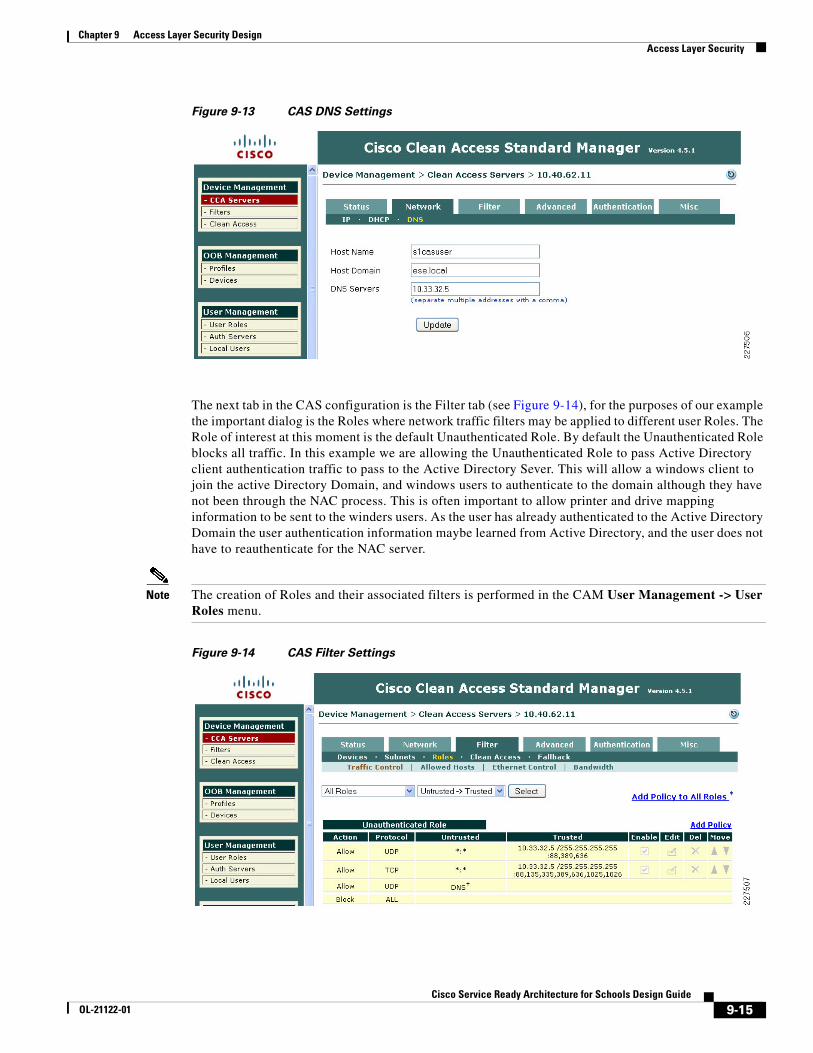
Figure 9-13 CAS DNS Settings
The next tab in the CAS configuration is the Filter tab (see Figure 9-14), for the purposes of our example the important dialog is the Roles where network traffic filters may be applied to different user Roles. The Role of interest at this moment is the default Unauthenticated Role. By default the Unauthenticated Role blocks all traffic. In this example we are allowing the Unauthenticated Role to pass Active Directory client authentication traffic to pass to the Active Directory Sever. This will allow a windows client to join the active Directory Domain, and windows users to authenticate to the domain although they have not been through the NAC process. This is often important to allow printer and drive mapping information to be sent to the winders users. As the user has already authenticated to the Active Directory Domain the user authentication information maybe learned from Active Directory, and the user does not have to reauthenticate for the NAC server.
Note The creation of Roles and their associated filters is performed in the CAM User Management -> User Roles menu.
Figure 9-14 CAS Filter Settings
9-15Cisco Service Ready Architecture for Schools Design Guide
OL-21122-01

Chapter 9 Access Layer Security Design Access Layer Security
The next tab that requires configuration is the Advanced tab. This has multiple dialogs that require configuration. The first of these is the Managed Subnet dialog, where each of the trusted VLAN subnets is added to the CAS for management. An example of this shown in Figure 9-15.
Figure 9-15 CAS Managed Subnet
The next dialog of the Advanced Tab is the VLAN Mapping dialog, which tells the CAS which trusted VLAN to be mapped to an untrusted VLAN, an example of this is shown in Figure 9-16. In our example VLAN Prunning and VLAN Mapping is also enabled.
Figure 9-16 VLAN Mapping
9-16Cisco Service Ready Architecture for Schools Design Guide
OL-21122-01

Chapter 9 Access Layer Security Design Access Layer Security
The next tab of interest is the Authentication Tab (see Figure 9-17), this tab has multiple dialogs for configuring different authentication options. The first dialog is the Login Page Dialog. This allows the configuration of different web login pages depending upon the untrusted subnet being used for authenticating client.
Figure 9-17 Authentication Login Page
The other Authentication dialog of interest in this example is the Windows Auth dialog, as Windows Single Sign On (SSO) is used in this example. To perform Windows SSO the CAS needs to be able to communicate with Active Directory to determine the authentication state of the windows user. If Active Directory confirms that the user has authenticated to Active Directory the user doesn't need to perform additional authentication to the CAS. An example of this configuration is shown in Figure 9-18. There are a number of steps required configure Active Directory SSO, as these are described in the Cisco NAC Appliance —Clean Access Server Installation and Configuration Guide. The key components in this configuration are:
• The creation of a Active Directory client account for the CAS
• Using the KTPass Application on Active Directory to convert the account encryption to DES encryption
9-17Cisco Service Ready Architecture for Schools Design Guide
OL-21122-01

Chapter 9 Access Layer Security Design Access Layer Security
Figure 9-18 CAS Windows Authentication
Clean Access Roles
The unauthenticated role is common to all clients, but once the client has been authenticated a different role may be applied based upon the identity of the client, different roles may be assigned for admin staff, teachers, or students.
User roles allow you to aggregate various policies into a user role. These policies include:
• Traffic policies
• Bandwidth policies
Note If bandwidth policies are to be enforced by the Clean Access Server it must be operating in band.
• VLAN ID retagging
• Clean Access network port scanning plugins
• Clean Access Agent/Cisco NAC Web Agent client system requirements
For example, an Admin, Teacher and Student roles could each have different traffic polices and VLANs, in addition the Student Role may enforce bandwidth policies by keeping the Student Traffic In band.
For more information on roles, refer to the Cisco NAC Appliance - Clean Access Manager Installation and Configuration Guide at the following URL:
http://www.cisco.com/en/US/docs/security/nac/appliance/configuration_guide/45/cam/45cam-book.html
Layer 2 OOB Example
Figure 9-19 shows an example of a Layer-2 OOB deployment. Where a wired client connected to an access switch is originally on the untrusted VLAN 264 and is switched to a trusted VLAN 64 once it has completed the NAC functions. The first NAC function is the authentication and authorization function, and this is the first design decision in implementing the NAC solution. That is, how will authentication and authorization be achieved, and what will the user experience be.
9-18Cisco Service Ready Architecture for Schools Design Guide
OL-21122-01

Chapter 9 Access Layer Security Design Access Layer Security
This example is focused upon the virtual gateway example, as virtual gateway provides the simplest deployment. In the virtual gateway example the original IP addressing, interfaces, and VLANs are maintained, and normal traffic flows are maintained. The only changes are the addition of the untrusted VLANs that carry client traffic during the NAC Authentication and Authorization, Scanning and evaluation, remediation, and quarantine modes.
Figure 9-19 Layer 2 OOB Example
NAC Authentication Options
The authentication option in the NAC solution can be broadly categorized as NAC Authentication or NAC Single Sign On
• NAC Authentication—NAC authentication gives the NAC system the role of authenticating users, a user database, either local to the NAC system or a separate system such as RADIUS, or LDAP
• NAC Single Sign On—NAC SSO, addresses systems that already perform authentication as part of their normal operation. For example 802.1X, VPN access, or Active Directory. NAC SSO learns the authentication state of clients through RADIUS accounting, or Active Director and therefore doesn't require the user to reenter authentication.
Topology Considerations
The Layer-2 OOB solution relies upon their being a Layer-2 network connection available between the the client devices and the Cisco CAS, in figure 5 a trunk connects the access switch to the core/distribution switch. The Cisco CAS is connected to the core/distribution switch through two
L2 UntrustedVLAN 264
VLAN 64VLAN 264
CAS
CAM10.40.94.15 AD
L2 TrustedVLAN 64
2275
12
MetroESchool District Network
9-19Cisco Service Ready Architecture for Schools Design Guide
OL-21122-01

Chapter 9 Access Layer Security Design Access Layer Security
interfaces—trusted and untrusted. In such a simple network it is relatively easy to provide a Layer-2 connection between the client and the Cisco CAS, for larger networks Layer-3 OOB, which is discussed later in this section, may be a better choice.
The roles of the untrusted and trusted interfaces:
• Untrusted Interface—The untrusted interface connects the client to the to the Cisco CAS during the NAC Authentication and Authorization, Scanning and Evaluation, Remediation, and Quarantine modes
• Trusted Interface—The trusted interface connects the NAC CAS to the “normal” network interface. This makes a network connection available to the CAS while it is sitting between the client and the network, thus allowing client access to services such as DHCP and DNS -and user defined services. Once a client has successfully completed its authentication and scanning phases, the CAM uses SNMP to change the client VLAN, on the access switch, from the untrusted VLAN to the trusted VLAN. Thus providing a direct connection to the network that was on the other side of the CAS (the trusted network).
Availability Considerations
Both the CAS and CAM are both highly involved in client network access, and consideration must be given to the impact on clients if either a CAS or CAM should fail or need to be taken out of service for a period of time.
The CAS is inline with client devices during the authentication, authorization, and posture assessment phases of NAC, and if “In Band NAC” is being used it may be inline at all times. A CAS outage in an OOB deployment would not impact already connected clients but would prevent network access for new clients. A CAS outage for “In Line” clients prevents access for all clients.
In situations where availability of a CAS is critical an HA CAS solution may be implemented where a pair of CAS servers are installed using a primary CAS, and a secondary in hot standby. For more information refer to the Cisco NAC Appliance - Clean Access Server Installation and Configuration Guide.
The CAM is also a critical part of the authentication, authorization, and posture assessment phases of NAC, although it doesn't pass client traffic, it the impact of its availability needs to be considered in the network design as well. Like the CAS the CAM has a HA solution that provides for a primary server and a hot standby secondary server. In addition, each CAS may be configured with a “fallback” option (as shown in Figure 9-20) that defines how it will manage client traffic in a situation where the CAM is unavailable.
In both HA CAM, and HA CAS, HA licenses are use that address the HA role of the server.
The use of the HA features will be dependent upon a Schools requirements, but CAS fallback should always configured to ensure that critical network services are available in even of a network outage.
9-20Cisco Service Ready Architecture for Schools Design Guide
OL-21122-01

Chapter 9 Access Layer Security Design Access Layer Security
Figure 9-20 CAS Fallback
Basic Clean Access switch Configuration For OOB-based Clean Access some simple configuration must be performed on the switches implementing NAC This configuration is primarily to enable SNMP communication between the switches and the CAM. Table 9-2 shows a simple SNMP v1 configuration (SNMPv2c and SNMPv3 are supported).
In addition to the switch SNMP configuration, the required trusted and untrusted VLANs must exist and be operational on the switch. If a switch has more than one IP address the snmp-server source interface must be specified, as the CAM must be configured with the source IP address that OOB SNMP messages will originate from, alternatively all IP addresses of interfaces on the switch can be added to the CAM. If SNMP access filtering is applied on the switch (as recommended as a best practice) the CAM must be added as a trusted address.
Basic Clean Access Out of Band Switch configuration
Table 9-2 SNMPv1 Configuration
Switch Port Configuration Global Switch Configuration
snmp trap mac-notification change added
snmp-server enable traps mac-notification snmp-server enable traps snmp linkup linkdown mac-address-table aging-time 3600 snmp-server host 172.16.1.61 traps version 1 cam_v1 udp-port 162 mac-notification snmp
9-21Cisco Service Ready Architecture for Schools Design Guide
OL-21122-01

Chapter 9 Access Layer Security Design Access Layer Security
802.1X Protected PortsThe best and most secure solution to vulnerability at the access edge is to leverage the intelligence of the network. The Cisco IBNS solution is a set of Cisco IOS software services designed to enable secure user and host access to enterprise networks powered by Cisco Catalyst switches and wireless LANs. It provides standards-based network access control at the access layer by using the 802.1X protocol to secure the physical ports where end users connect. 802.1X is an IEEE standard for media-level (Layer 2) access control, offering the capability to permit or deny network connectivity based on the identity of the end user or device. 802.1X is well-known as a way to secure wireless network access. It is equally essential in securing wired network access.
What is 802.1X?
The IEEE 802.1X protocol allows Cisco Catalyst switches to offer network access control at the port level. Every port on the switch is individually enabled or disabled based on the identity of the user or device connecting to it. When 802.1X is first enabled on a port, the switch automatically drops all traffic received on that port. There is one exception to this rule. The only traffic a switch will accept is a request to start 802.1X authentication. Only after the 802.1X authentication has successfully completed will the switch accept any other kind of traffic on the port.
The high-level message exchange in Figure 9-21 illustrates how port-based access control works within an identity-based system. First, a client, such as a laptop equipped with an 802.1X supplicant, connects to an IEEE 802.1X-enabled network and sends a start message to the LAN switch the authenticator. Once the start message is received, the LAN switch sends a login request to the client and the client replies with a login response. The switch forwards the response to the policy database authentication server which authenticates the user. After the user identity is confirmed, the policy database authorizes network access for the user and informs the LAN switch. The LAN switch then enables the port connected to the client.
Figure 9-21 Port-Based Access Control
2275
15
EAPOL Start1
Login Request2
Login Response3
Check with Policy DB4
Switch Enables Port7
Policy DB ConfirmsID and Grants Access
5
Policy DB Informs Switch6
AuthenticationServer
Authenticator
9-22Cisco Service Ready Architecture for Schools Design Guide
OL-21122-01

Chapter 9 Access Layer Security Design Access Layer Security
User or device credentials are processed by a AAA server. The AAA server is able to reference user or device policy profile information either internally, using the integrated user database, or externally, using database sources such as Microsoft Active Directory, LDAP, Novell NDS or Oracle databases. This enables the integration of the system into exiting user management structures and schemes, thereby simplifying overall deployment.
802.1X and EAP
When authenticating users for the purposes of network access control, the system must provide user and/or device identification using strong authentication technologies known to be secure and reliable. IEEE 802.1X does not by itself dictate how this is achieved. Rather, the 802.1X protocol defines an encapsulation for the transport of the Extensible Authentication Protocol (EAP) from the client to the switch. The 802.1X encapsulation is sometimes referred to as EAP over LAN (EAPoL). The switch in turn relays the EAP information to the authentication server using the RADIUS protocol (EAP over RADIUS).
EAP, which is defined by RFC 3748, is itself a framework---not a specific authentication method. EAP provides a way for the client and the authentication server to negotiate an authentication method that they both support. There are many EAP methods but the ones used more frequently for 802.1X wired authentication include EAP-TLS, EAP-PEAP, and EAP-FAST.
How 802.1X Impacts the NetworkBefore enabling 802.1X in the network, it is essential to review the default security posture of a port enabled for 802.1X authentication: all traffic is dropped except 802.1X EAPoL packets. This is a fundamental change from the traditional model in which the port is enabled and all traffic is allowed from the moment that a device plugs into the port. Ports that were traditionally open will now be closed by default. This is one of the cornerstones of the strong security and network access control provided by 802.1X. However, this change in the default network access model can have a profound impact on network devices and applications. Understanding and providing for the impacts of this change will make for a smooth deployment of 802.1X network access control.
Non-802.1X-Enabled Devices
802.1X must be enabled on both the host device and on the switch to which the device connects. If a device without an 802.1X supplicant attempts to connect to a port that is enabled for 802.1X, it will be subjected to the default security policy. The default security policy says that 802.1X authentication must succeed before access to the network is granted. Therefore, by default, non-802.1X-capable devices cannot get access to an 802.1X-protected network.
Although many devices increasingly support 802.1X, there will always be devices that require network connectivity but do not and/or cannot support 802.1X. Examples of such devices include network printers, badge readers, legacy servers, and PXE boot machines. Some provision must be made for these devices.
Cisco provides two features to accommodate non-802.1X devices. These are MAC Authentication Bypass (MAB) and the Guest VLAN. These features provide fallback mechanisms when there is no 802.1X supplicant. After 802.1X times out on a port, the port can move to an open state if MAB succeeds or if the Guest VLAN is configured. Judicious application of either or both of these features will be required for a successful 802.1X deployment.
9-23Cisco Service Ready Architecture for Schools Design Guide
OL-21122-01

Chapter 9 Access Layer Security Design Access Layer Security
Note Network-specific testing will be required to determine the optimal values for 802.1X timers to accommodate the various non-802.1X-capable devices on your network.
802.1X in SchoolsAs mentioned above on the requirement for 802.1X authentication is the requirement for a supplicant. This has typically been a challenge in the schools environment with a wide range of the devices and limited or no management of many of these devices. In many schools this is still the case, and this makes a district wide 802.1X very challenging. At the same time there are pockets of a school network where 802.1X may be a good choice.
For example 802.1X protected ports may be a good choice for the network ports in the District Office, and the school administrator office, as these locations are more likely to have managed PCs.
Other locations in the schools network still need protection, but student network access may be better served by a NAC Appliance solution. Network access ports in open areas such as classrooms may use 802.1X or Cisco Clean Access NAC to protect these ports.
When considering the 802.1X deployment, there are four main 802.1X authentication options to consider.
• Basic 802.1X Authentication—An 802.1X controlled port with an 802.1X client directly connected
• IP Phone Ports—An IP Phone and an 802.1X controlled port with an 802.1X client connected to the phone
• MAC Auth By-Pass—Using the MAC address of the client to provide authentication and bypass the 802.1X authentication process. Printer and legacy device support are typical applications
• Web Auth—Allowing a user to authenticate by entering username and passwords in a web page. Legacy device support and guest access are typical deployment applications
Basic 802.1X Switch ConfigurationThe basic 802.1X configuration controls access to an access VLAN depending upon the success or failure of the an 802.1X authentication. If the 802.1X authentication is successful, there are three basic options:
• Access to the VLAN configured on the switch port
• Access to the VLAN configured on the switch port an controlled by a access list downloaded from the AAA server
• Access to a VLAN passed to the switch by the AAA server
Table 9-3 shows example 802.1X configurations.
9-24Cisco Service Ready Architecture for Schools Design Guide
OL-21122-01

Chapter 9 Access Layer Security Design Access Layer Security
For more information upon the 3750 802.1X configuration refer to the following documents:
Catalyst 3750-E and 3560-E Switch Software Configuration Guide, 12.2(50)SE ->Configuring IEEE 802.1x Port-Based Authentication
http://www.cisco.com/en/US/docs/switches/lan/catalyst3750e_3560e/software/release/12.2_50_se/configuration/guide/sw8021x.html
Catalyst 2960 Switch Software Configuration Guide, Rel. 12.2(50)SE Configuring IEEE 802.1x Port-Based Authentication
http://www.cisco.com/en/US/docs/switches/lan/catalyst2960/software/release/12.2_50_se/configuration/guide/sw8021x.html
NAC 802.1X and CISF in CombinationThe three key access security features discussed above have been discussed in isolation, but can be combined. In particular, the CISF features should be considered “baseline” features that are applied on all access ports, and either NAC or 802.1X maybe overlaid on top of the CiSF configuration.
The Cisco Clean Access and 802.1X configuration are also compatible (although they are not often combined in wired networks), the key consideration in combining the two is how to give the appearance of a SSO for the end user. Both 802.1X and NAC require authentication, as 802.1X authenticates the client initially, a mechanism of communicating the 802.1X authentication result to the Cisco Clean Access system is required.
If the authenticating clients join an Windows Active Directory network, the Cisco Clean Access Active Directory SSO feature allows the clients to authenticate to active directory once they have performed there 802.1X authentication. The CAM, when a client is detected, checks Active Directory to see if the client has authenticated; this allows a SSO experience for client devices that are using 802.1X and NAC.
DMP PortsA DMP connection to the network is like that of a typical IP client. There should only be one MAC address and one IP address on that port. This means that typical PC client port security settings will work.
An DMP is primarily are receiver for packets, but if traffic classification from the DMP is important the DSCP from the DMP should trusted
Table 9-3 802.1X Switch Configuration
Example 3750 802.1X PC Port Configuration Example 3750 Global Configuration
authentication port-control auto authentication periodic dot1x pae authenticator
aaa new-model aaa authentication dot1x default group radius dot1x system-auth-control ip radius source-interface Vlan300 radius-server host 10.40.62.9 auth-port 1812 acct-port 1813 key cisco radius-server host 10.40.94.9 auth-port 1812 acct-port 1813 key cisco
9-25Cisco Service Ready Architecture for Schools Design Guide
OL-21122-01

Chapter 9 Access Layer Security Design Access Layer Security
Surveillance Camera PortAn the Surveillance Camera connection to the network is like that of a typical IP client. There should only be one MAC address and one IP address on that port. This means that typical PC client port security settings will work.
An the camera marks packets with DSCP marking based upon its configured QoS policies. Therefore, to ensure that the QoS policy is effective the network must trust the DSCP Markings from the camera.
Power-over-EthernetThe APs in the Schools SRA are 802.11n APs, and can provide greater than 100Mbps throughput, and therefore they should use 1-Gigabit Ethernet.
An LWAPP AP connection to the network is like that of a typical IP client. There should only be one MAC address and one IP address on that port. This means that typical PC client port security settings will work. If 802.1X is used on the network the APs are able to act as 802.1X supplicants and authenticate to the network. An LWAPP AP marks the LWAPP packets with DSCP marking based upon the CUWN QoS policies. Therefore to ensure that the QoS policy is effective the network must trust the DSCP Markings from the AP.
If the switch or module supports PoE, it may be able to power the APs connected to its ports.
Although the LWAPP APs can connect to the network in the same manner as a trusted PC client, it is recommend that the LWAPP APs have their own dedicated subnet and VLAN. This makes AP specific policies easier to implement within the network, and generally make network management tasks easier.
1250 Power-over-Ethernet
Today's PoE standard, 802.3af, peaks at getting 15.4 watts to the devices it powers. Unfortunately, 11n requires a bit more power in order to realize the new standard's full potential. As a result, the Aironet 1250 Series access point requires 18.5 watts in full operational mode.*Note:*There is no getting around the higher power requirements of 11n unless you either remove a radio (the Aironet 1250 Series access point can run with a single radio on 802.3af) or remove valuable 11n functionality. Though others may opt to do so, Cisco has chosen not to remove 11n's key features (such as spatial division multiplexing support or multiple transmitters/receivers) in order to allow it to be powered with legacy PoE infrastructure.How can you still use PoE functionality for a device that requires more wattage than the current standard delivers? Midspan PoE, in which an injector powers the AP, is the simple answer. Just make sure you purchase an injector that can support the additional power requirements. These can be ordered along with the Aironet 1250 or separately; the midspan PoE injector part number is AIR-PWRINJ4= and the AC adapter is AIR-PWR-SPLY1=). End-span PoE, in which the AP pulls power from the switch to which it is connected, requires a bit more planning.In 2005, the IEEE came together to address the issue of increasing power requirements and formed the 802.3at Working Group to push through a higher power PoE standard. This new standard has yet to be ratified, which would make it a full, industry-accepted protocol, but it does provide an archetype by which up to 30 watts may be delivered to a device across existing Cat5 cabling. While 802.3at makes its way through the approval process, Cisco provides an enhanced PoE (often called PoE Plus) option available in some of its flagship switching products.Using Cisco Discover Protocol (CDP) and robust power subsystem engineering, Cisco offers the Cisco Catalyst®3560E and 3750E with additional support (beyond the 802.3af specification) for customers who wish to fully power a dual-radio Aironet 1250 Series access point.If you decide that powering an Aironet 1250 Series access point via 802.2af is so important that you are willing to forgo supporting either 2.4 GHz (11b/g/n) or 5 GHz (11a/n), you can use just one RF band. In
9-26Cisco Service Ready Architecture for Schools Design Guide
OL-21122-01

Chapter 9 Access Layer Security Design Access Layer Security
such cases, plan to support a 2.4-GHz environment (due to the overwhelming majority of clients that support this spectrum) and upgrade to support 5 GHz when budgetary, infrastructure, and user needs align.
1140 Power-over-Ethernet (PoE)
The Cisco 1140 access point is 802.3af (15.4 W)-compliant and can be powered by any of the following 802.3af compliant devices: 2106 controller-WS-C3550, WS-C3560, and WS-C3750 switches-C1880 switch-2600, 2610, 2611, 2621, 2650, and 2651 multiservice platforms-2610XM, 2611XM, 2621XM, 2650XM, 2651XM, and 2691 multiservice platforms-2811, 2821, and 2851 integrated services routers-3620, 3631-telco, 3640, and 3660 multiservice platforms-3725 and 3745 multiservice access routers-3825 and 3845 integrated services routers-Any 802.3af compliant power injector.
Note The Cisco 1140 Series access point requires a Gigabit Ethernet link to prevent the Ethernet port from becoming a bottleneck for traffic because wireless traffic speeds exceed transmit speeds of a 10/100 Ethernet port.
Note The Cisco 1250 Series access point can also be powered by a power injector (AIR-PWRINJ4) or local power (AIR-PWR-SPLY).
IP PhonesThe IP phones used in the Schools SRA are all able to use Power-over-Ethernet (PoE) and are able to be powered by any of the PoE access switches discussed in this guide.
9-27Cisco Service Ready Architecture for Schools Design Guide
OL-21122-01

Chapter 9 Access Layer Security Design Access Layer Security
9-28Cisco Service Ready Architecture for Schools Design Guide
OL-21122-01