Embed Size (px)
Citation preview
Acceptance and re-verification tests forCoordinate Measuring Machines.A brief introduction.
2
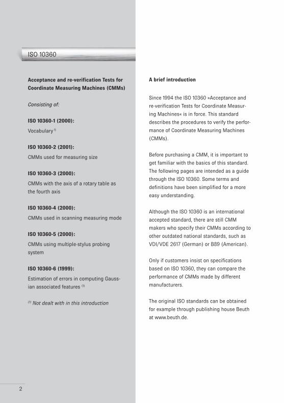
ISO 10360
Acceptance and re-verification Tests for
Coordinate Measuring Machines (CMMs)
Consisting of:
ISO 10360-1 (2000):
Vocabulary 1)
ISO 10360-2 (2001):
CMMs used for measuring size
ISO 10360-3 (2000):
CMMs with the axis of a rotary table as
the fourth axis
ISO 10360-4 (2000):
CMMs used in scanning measuring mode
ISO 10360-5 (2000):
CMMs using multiple-stylus probing
system
ISO 10360-6 (1999):
Estimation of errors in computing Gauss-
ian associated features (1)
(1) Not dealt with in this introduction
A brief introduction
Since 1994 the ISO 10360 »Acceptance and
re-verification Tests for Coordinate Measur-
ing Machines« is in force. This standard
describes the procedures to verify the perfor-
mance of Coordinate Measuring Machines
(CMMs).
Before purchasing a CMM, it is important to
get familiar with the basics of this standard.
The following pages are intended as a guide
through the ISO 10360. Some terms and
definitions have been simplified for a more
easy understanding.
Although the ISO 10360 is an international
accepted standard, there are still CMM
makers who specify their CMMs according to
other outdated national standards, such as
VDI/VDE 2617 (German) or B89 (American).
Only if customers insist on specifications
based on ISO 10360, they can compare the
performance of CMMs made by different
manufacturers.
The original ISO standards can be obtained
for example through publishing house Beuth
at www.beuth.de.
3
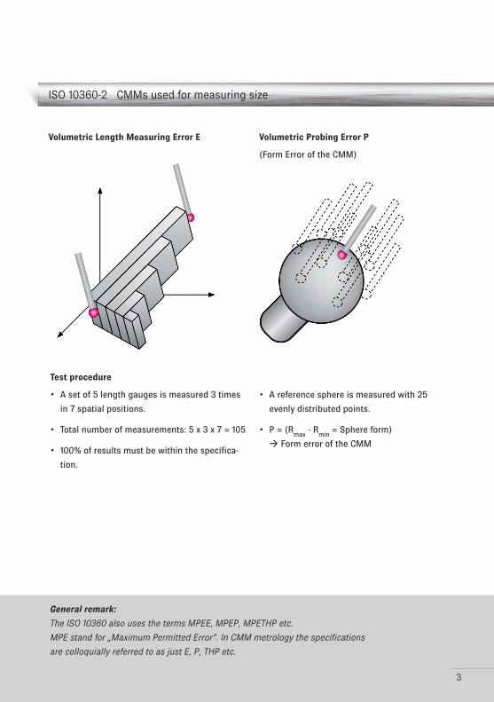
Volumetric Length Measuring Error E
ISO 10360-2 CMMs used for measuring size
Test procedure
A set of 5 length gauges is measured 3 times •
in 7 spatial positions.
Total number of measurements: 5 x 3 x 7 = 105•
100% of results must be within the specifica-•
tion.
Volumetric Probing Error P
(Form Error of the CMM)
A reference sphere is measured with 25 •
evenly distributed points.
P = (R•max
- Rmin
= Sphere form)
Form error of the CMM
General remark:
The ISO 10360 also uses the terms MPEE, MPEP, MPETHP etc.
MPE stand for „Maximum Permitted Error“. In CMM metrology the specifications
are colloquially referred to as just E, P, THP etc.
4
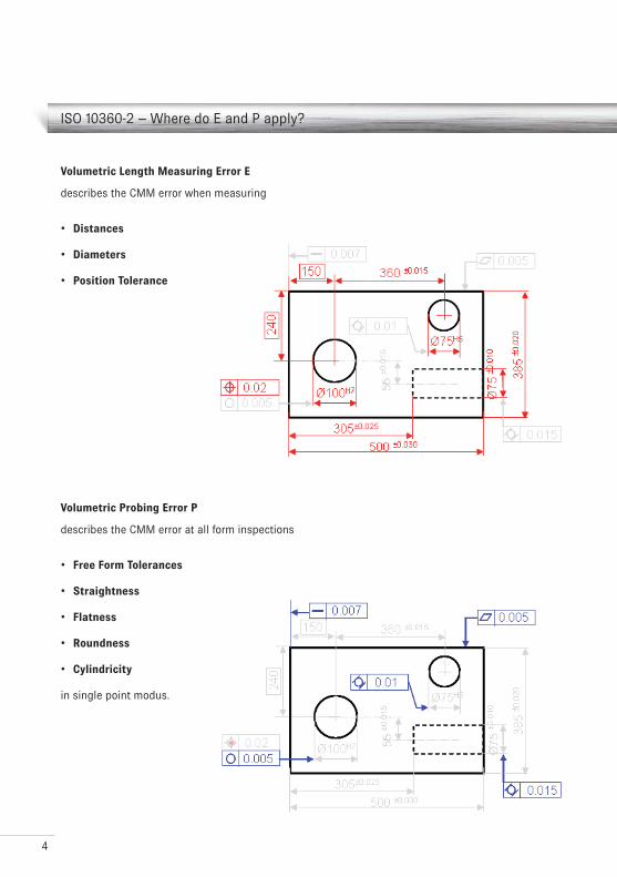
ISO 10360-2 – Where do E and P apply?
Volumetric Length Measuring Error E
describes the CMM error when measuring
Distances•
Diameters•
Position Tolerance•
Volumetric Probing Error P
describes the CMM error at all form inspections
Free Form Tolerances•
Straightness•
Flatness•
Roundness•
Cylindricity•
in single point modus.
5
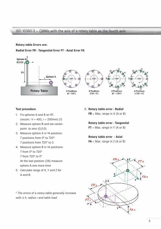
ISO 10360-3 – CMMs with the axis of a rotary table as the fourth axis
Test procedure
1. Fix spheres A and B on RT.
(recom.: h = 400, r = 200mm).(1)
2. Measure sphere B and set center-
point to zero (0,0,0).
3. Measure sphere A in 14 positons:
7 positions from 0° to 720°
7 positions from 720° to 0.
4. Measure sphere B in 14 positions:
7 from 0° to 720°
7 from 720° to 0°
At the last position (28) measure
sphere A one more time
5. Calculate range of X, Y and Z for
A and B.
1) The errors of a rotary table generally increase
with ∆ h, radius r and table load.
6. Rotary table error - Radial
FR = Max. range in X (A or B)
Rotary table error - Tangential
FT = Max. range in Y (A or B)
Rotary table error - Axial
FA = Max. range in Z (A or B)
Rotary table Errors are:
Radial Error FR - Tangential Error FT - Axial Error FA
6
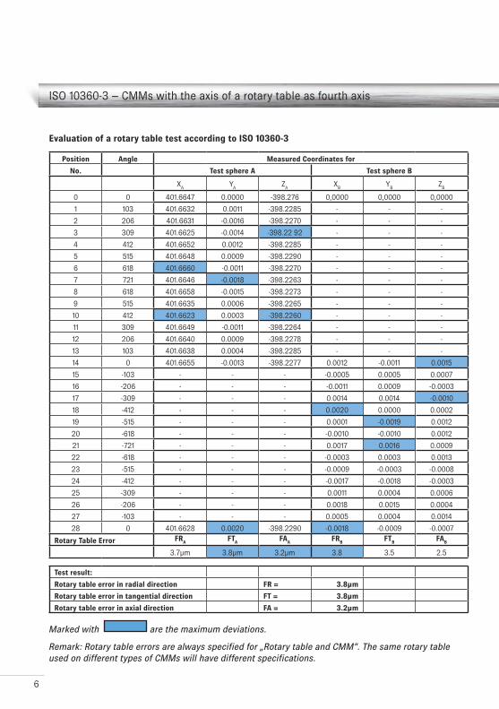
ISO 10360-3 – CMMs with the axis of a rotary table as fourth axis
Evaluation of a rotary table test according to ISO 10360-3
Marked with are the maximum deviations.
Remark: Rotary table errors are always specified for „Rotary table and CMM“. The same rotary table used on different types of CMMs will have different specifications.
Position Angle Measured Coordinates for
No. Test sphere A Test sphere B
XA
YA
ZA
XB
YB
ZB
0 0 401.6647 0.0000 -398.276 0,0000 0,0000 0,0000
1 103 401.6632 0.0011 -398.2285 - - -
2 206 401.6631 -0.0016 -398.2270 - - -
3 309 401.6625 -0.0014 -398.22 92 - - -
4 412 401.6652 0.0012 -398.2285 - - -
5 515 401.6648 0.0009 -398.2290 - - -
6 618 401.6660 -0.0011 -398.2270 - - -
7 721 401.6646 -0.0018 -398.2263 - - -
8 618 401.6658 -0.0015 -398.2273 - - -
9 515 401.6635 0.0006 -398.2265 - - -
10 412 401.6623 0.0003 -398.2260 - - -
11 309 401.6649 -0.0011 -398.2264 - - -
12 206 401.6640 0.0009 -398.2278 - - -
13 103 401.6638 0.0004 -398.2285 - - -
14 0 401.6655 -0.0013 -398.2277 0.0012 -0.0011 0.0015
15 -103 - - - -0.0005 0.0005 0.0007
16 -206 - - - -0.0011 0.0009 -0.0003
17 -309 - - - 0.0014 0.0014 -0.0010
18 -412 - - - 0.0020 0.0000 0.0002
19 -515 - - - 0.0001 -0.0019 0.0012
20 -618 - - - -0.0010 -0.0010 0.0012
21 -721 - - - 0.0017 0.0016 0.0009
22 -618 - - - -0.0003 0.0003 0.0013
23 -515 - - - -0.0009 -0.0003 -0.0008
24 -412 - - - -0.0017 -0.0018 -0.0003
25 -309 - - - 0.0011 0.0004 0.0006
26 -206 - - - 0.0018 0.0015 0.0004
27 -103 - - - 0.0005 0.0004 0.0014
28 0 401.6628 0.0020 -398.2290 -0.0018 -0.0009 -0.0007
Rotary Table Error FRA
FTA
FAA
FRB
FTB
FAB
3.7µm 3.8µm 3.2µm 3.8 3.5 2.5
Test result:
Rotary table error in radial direction FR = 3.8µm
Rotary table error in tangential direction FT = 3.8µm
Rotary table error in axial direction FA = 3.2µm
2
1
3
4
7
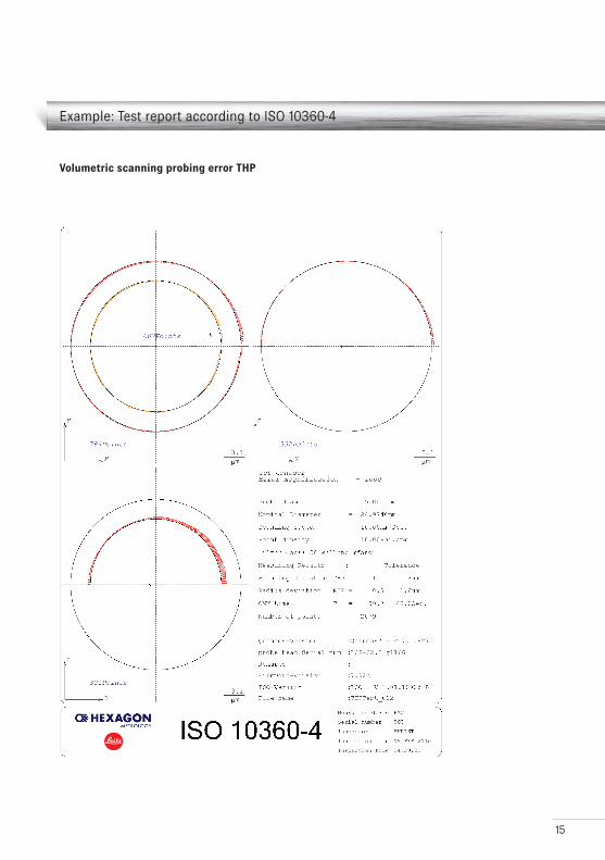
ISO 10360-4 – CMMs used in scanning measuring mode
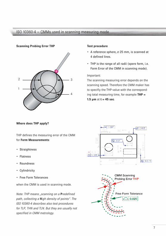
Scanning Probing Error THP
Where does THP apply?
THP defines the measuring error of the CMM
for Form Measurements:
Straightness•
Flatness•
Roundness•
Cylindricity•
Free Form Tolerances•
when the CMM is used in scanning mode.
Note: THP means „scanning on a Predefined
path, collecting a High density of points“. The
ISO 10360-4 describes also test procedures
for TLP, THN and TLN. But they are usually not
specified in CMM metrology.
Test procedure
A reference sphere,• Ø 25 mm, is scanned at
4 defined lines.
THP is the range of all radii (spere form, i.e. •
Form Error of the CMM in scanning mode).
Important:
The scanning measuring error depends on the
scanning speed. Therefore the CMM maker has
to specifiy the THP-value with the correspond-
ing total measuring time, for example THP =
1.5 µm at t = 45 sec.
8
ISO 10360-5 – CMMs using multiple-stylus probing system
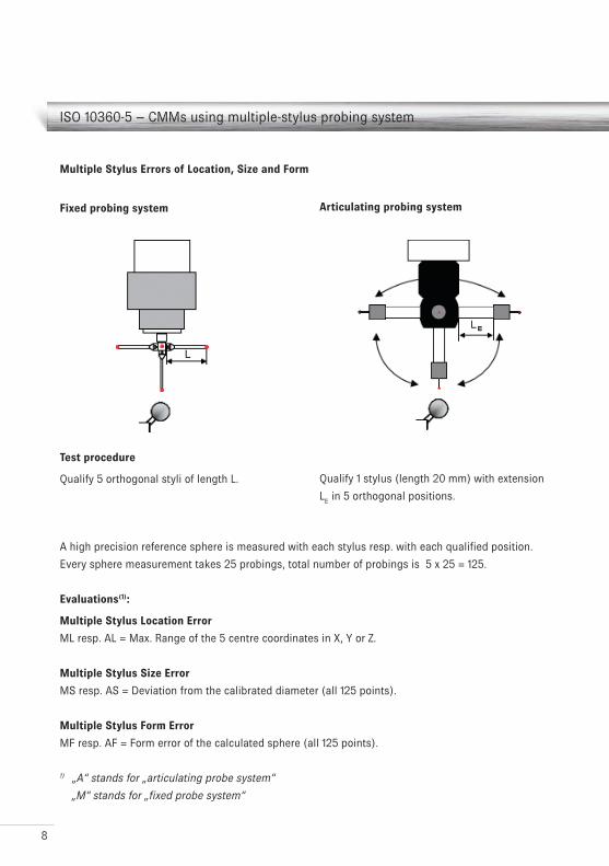
Multiple Stylus Errors of Location, Size and Form
Fixed probing system
Test procedure
Qualify 5 orthogonal styli of length L. Qualify 1 stylus (length 20 mm) with extension
LE in 5 orthogonal positions.
A high precision reference sphere is measured with each stylus resp. with each qualified position.
Every sphere measurement takes 25 probings, total number of probings is 5 x 25 = 125.
Evaluations(1):
Multiple Stylus Location Error
ML resp. AL = Max. Range of the 5 centre coordinates in X, Y or Z.
Multiple Stylus Size Error
MS resp. AS = Deviation from the calibrated diameter (all 125 points).
Multiple Stylus Form Error
MF resp. AF = Form error of the calculated sphere (all 125 points).
1) „A“ stands for „articulating probe system“
„M“ stands for „fixed probe system“
Articulating probing system
9
ISO 10360-5 – CMMs using multiple-stylus probing system
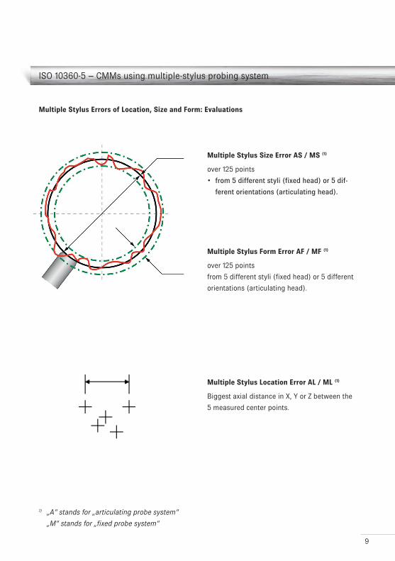
Multiple Stylus Errors of Location, Size and Form: Evaluations
Multiple Stylus Location Error AL / ML (1)
Biggest axial distance in X, Y or Z between the
5 measured center points.
Multiple Stylus Form Error AF / MF (1)
over 125 points
from 5 different styli (fixed head) or 5 different
orientations (articulating head).
1) „A“ stands for „articulating probe system“
„M“ stands for „fixed probe system“
Multiple Stylus Size Error AS / MS (1)
over 125 points
from 5 different styli (fixed head) or 5 dif-•
ferent orientations (articulating head).
10
ISO 10360-5 – Where do AL, AS and AF apply?
Multi Stylus Probing Errors for CMMs with
articulating probe system
AL (Location),
AS (Size) and
AF (Form)
have to be considered, if for a measurement of
a feature the probe system has to be articu-
lated.
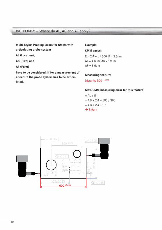
Example:
CMM specs:
E = 2.4 + L / 300; P = 2.8µm
AL = 4.8µm; AS = 1.9µm
AF = 8.6µm
Measuring feature:
Distance 500 ±0.030
Max. CMM measuring error for this feature:
= AL + E
= 4.8 + 2.4 + 500 / 300
= 4.8 + 2.4 + 1.7
8.9µm
11
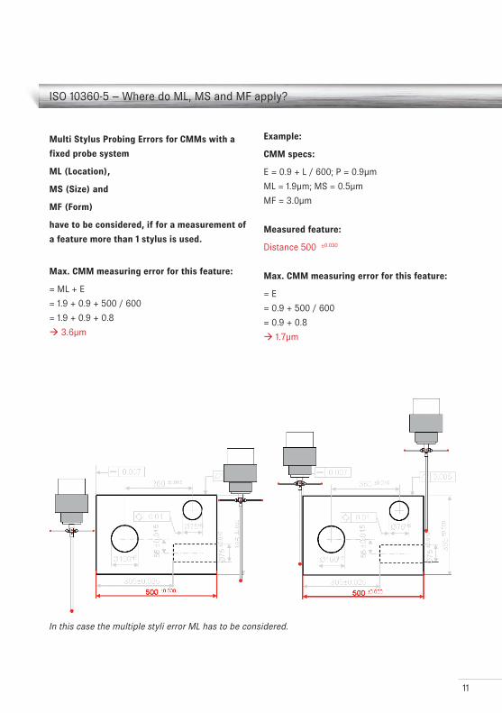
ISO 10360-5 – Where do ML, MS and MF apply?
Multi Stylus Probing Errors for CMMs with a
fixed probe system
ML (Location),
MS (Size) and
MF (Form)
have to be considered, if for a measurement of
a feature more than 1 stylus is used.
Max. CMM measuring error for this feature:
= ML + E
= 1.9 + 0.9 + 500 / 600
= 1.9 + 0.9 + 0.8
3.6µm
Example:
CMM specs:
E = 0.9 + L / 600; P = 0.9µm
ML = 1.9µm; MS = 0.5µm
MF = 3.0µm
Measured feature:
Distance 500 ±0.030
Max. CMM measuring error for this feature:
= E
= 0.9 + 500 / 600
= 0.9 + 0.8
1.7µm
In this case the multiple styli error ML has to be considered.
12
Attention should also be paid to the following restrictions
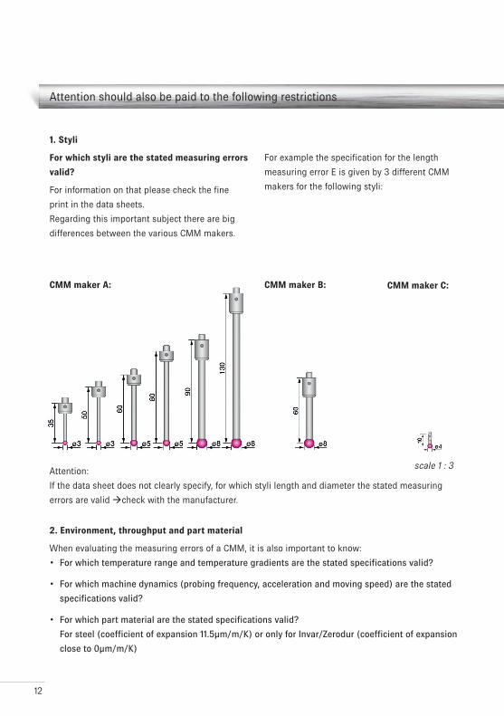
1. Styli
For which styli are the stated measuring errors
valid?
For information on that please check the fine
print in the data sheets.
Regarding this important subject there are big
differences between the various CMM makers.
CMM maker A: CMM maker B: CMM maker C:
2. Environment, throughput and part material
When evaluating the measuring errors of a CMM, it is also important to know:
For which temperature range and temperature gradients are the stated specifications valid?•
For which machine dynamics (probing frequency, acceleration and moving speed) are the stated •
specifications valid?
For which part material are the stated specifications valid? •
For steel (coefficient of expansion 11.5µm/m/K) or only for Invar/Zerodur (coefficient of expansion
close to 0µm/m/K)
For example the specification for the length
measuring error E is given by 3 different CMM
makers for the following styli:
scale 1 : 3Attention:
If the data sheet does not clearly specify, for which styli length and diameter the stated measuring
errors are valid check with the manufacturer.
13
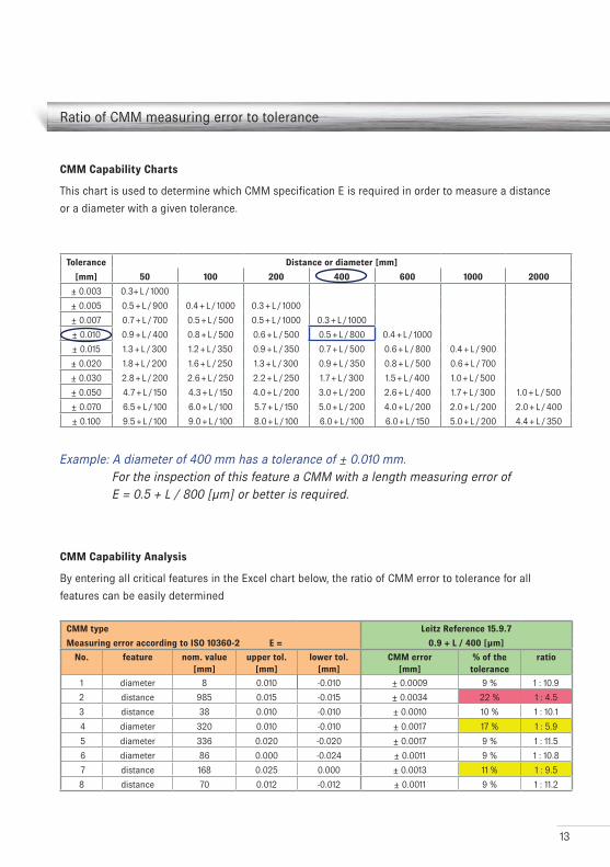
Ratio of CMM measuring error to tolerance
Tolerance Distance or diameter [mm]
[mm] 50 100 200 400 600 1000 2000
± 0.003 0.3+ L / 1000
± 0.005 0.5 + L / 900 0.4 + L / 1000 0.3 + L / 1000
± 0.007 0.7 + L / 700 0.5 + L / 500 0.5 + L / 1000 0.3 + L / 1000
± 0.010 0.9 + L / 400 0.8 + L / 500 0.6 + L / 500 0.5 + L / 800 0.4 + L / 1000
± 0.015 1.3 + L / 300 1.2 + L / 350 0.9 + L / 350 0.7 + L / 500 0.6 + L / 800 0.4 + L / 900
± 0.020 1.8 + L / 200 1.6 + L / 250 1.3 + L / 300 0.9 + L / 350 0.8 + L / 500 0.6 + L / 700
± 0.030 2.8 + L / 200 2.6 + L / 250 2.2 + L / 250 1.7 + L / 300 1.5 + L / 400 1.0 + L / 500
± 0.050 4.7 + L / 150 4.3 + L / 150 4.0 + L / 200 3.0 + L / 200 2.6 + L / 400 1.7 + L / 300 1.0 + L / 500
± 0.070 6.5 + L / 100 6.0 + L / 100 5.7 + L / 150 5.0 + L / 200 4.0 + L / 200 2.0 + L / 200 2.0 + L / 400
± 0.100 9.5 + L / 100 9.0 + L / 100 8.0 + L / 100 6.0 + L / 100 6.0 + L / 150 5.0 + L / 200 4.4 + L / 350
Example: A diameter of 400 mm has a tolerance of ± 0.010 mm. For the inspection of this feature a CMM with a length measuring error of E = 0.5 + L / 800 [µm] or better is required.
CMM Capability Charts
This chart is used to determine which CMM specification E is required in order to measure a distance
or a diameter with a given tolerance.
CMM Capability Analysis
By entering all critical features in the Excel chart below, the ratio of CMM error to tolerance for all
features can be easily determined
CMM type Leitz Reference 15.9.7
Measuring error according to ISO 10360-2 E = 0.9 + L / 400 [µm]
No. feature nom. value upper tol. lower tol. CMM error % of the ratio[mm] [mm] [mm] [mm] tolerance
1 diameter 8 0.010 -0.010 ± 0.0009 9 % 1 : 10.9
2 distance 985 0.015 -0.015 ± 0.0034 22 % 1 : 4.5
3 distance 38 0.010 -0.010 ± 0.0010 10 % 1 : 10.1
4 diameter 320 0.010 -0.010 ± 0.0017 17 % 1 : 5.9
5 diameter 336 0.020 -0.020 ± 0.0017 9 % 1 : 11.5
6 diameter 86 0.000 -0.024 ± 0.0011 9 % 1 : 10.8
7 distance 168 0.025 0.000 ± 0.0013 11 % 1 : 9.5
8 distance 70 0.012 -0.012 ± 0.0011 9 % 1 : 11.2
14
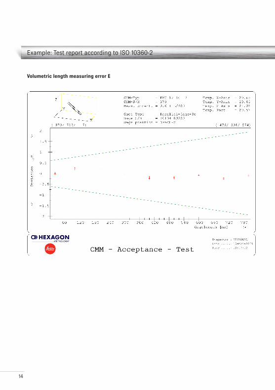
Example: Test report according to ISO 10360-2
Volumetric length measuring error E
15
Example: Test report according to ISO 10360-4
Volumetric scanning probing error THP
16
LeitzThe Leitz brand as part of Hexagon Metrologystands for high accuracy coordinate measuring machines, gear inspection centers and probes. Leitz measurement systems master quality as-surance tasks equally well both in metrology labs as well as on the shop floor. The development and production are located in Wetzlar, Germany. For more than 30 years Leitz has been offering its customers the best innovative measurement technology available. The primary goal remains offering modern solutions for demanding mea-surement tasks.
Hexagon MetrologyHexagon Metrology is part of the Hexagon group and brings leading brands from the field of industrial metrology under one roof.
Hexagon Metrology GmbHLeitz DivisionSiegmund-Hiepe-Straße 2 – 1235578 WetzlarGermany
E-mail [email protected] +49 (0) 6441 207 0Fax +49 (0) 6441 207 122
www.leitz-metrology.comwww.hexagonmetrology.com
M42-510-004-231
© 2010 Hexagon Metrology GmbH
All right reserved.
Printed in Switzerland. February 2010.7801
48