Embed Size (px)
Citation preview
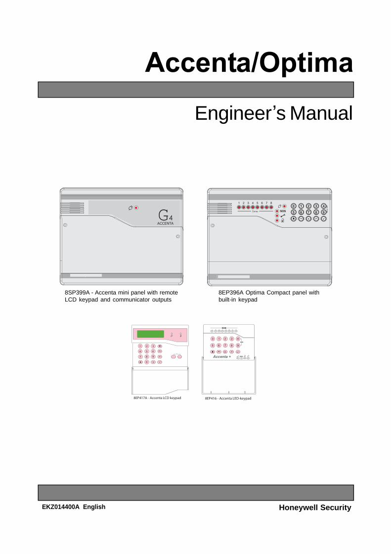
Engineer s Manual
Honeywell Security
8SP399A - Accenta mini panel with remoteLCD keypad and communicator outputs
8EP396A Optima Compact panel withbuilt-in keypad
EKZ014400A English

Accenta/Optima Engineer s Manual Table of Contents
i
ContentsIntroduction............................................................................................................ 1Features .................................................................................................................. 1Installation Design ................................................................................................ 2Fixing the Control Panel ....................................................................................... 3PCB.......................................................................................................................... 4Wiring the System................................................................................................. 4Tamper Network..................................................................................................... 4Connecting Remote Keypads............................................................................... 5Fitting the Remote Keypad................................................................................... 6Security Zones....................................................................................................... 6Fire Zone ................................................................................................................ 7PA Circuit ................................................................................................................ 8Extension Speaker ................................................................................................ 8External Siren (Bell Box) Output.......................................................................... 9
13V Supply Output ............................................................................................................. 10Set ........................................................................................................................................ 10
Remote Signalling Input and Outputs............................................................... 11Filtering of Intruder alarms............................................................................................... 12
Factory Set Condition......................................................................................... 13Mains Connection ............................................................................................... 14Testing the System.............................................................................................. 14First Power Up...................................................................................................... 15Engineer Program Mode..................................................................................... 16
Indications on LED Keypads............................................................................................ 16System Indications.............................................................................................. 16Entering/Exiting Engineer Program Mode........................................................ 17Defaulting Panel to Factory Settings ................................................................ 17Defaulting User Code 1 and Engineer Code..................................................... 17
Accenta/Optima Engineer s ManualTable of Contents
ii
Menu Options....................................................................................................... 180 = Walk Test ....................................................................................................................... 181 = Alarm Test ..................................................................................................................... 192 = Test Outputs ................................................................................................................. 203 = System Flags................................................................................................................ 214 = Time and Date............................................................................................................... 245 = Language...................................................................................................................... 246 = Zone Names.................................................................................................................. 247 = Timers............................................................................................................................ 258 = Codes............................................................................................................................. 28C = View Event Log ............................................................................................................ 30O = Omit Allow and Double Knock................................................................................... 31P = Programs ...................................................................................................................... 34
Operating the System.......................................................................................... 42Setting the System............................................................................................................. 42Resetting After an Alarm, Tamper or PA.......................................................................... 43Unsetting the System........................................................................................................ 43
Faults .................................................................................................................... 45Specifications ...................................................................................................... 46Appendix 1 - Event Log Messages.................................................................... 47Appendix 2 - Library............................................................................................ 49Servicing Organisation Details.......................................................................... 51Parts...................................................................................................................... 51

Accenta/Optima Engineer s Manual
1
IntroductionThis manual provides information on Installation design, panel fixing, wiring, power up and programming of theintruder panels.
Features
8 zones programmable for Security, 2 zones for Fire.
PA input.
Tamper input.
Outputs for External Siren (Bell) and Strobe.
4 Access level Codes, User 1, User 2, Engineer and Duress, all programmable.
3 fully selectable part set programs.
Chime on any security zone.
250 event memory (LCD Keypad), 8 event memory (LED keypad).
Programmable timers including bell cut off.
Walk Test facilities.
Quick set feature.
Supports up to four remote keypads with on board PA and illuminated keys positioned up to100 meters from the panel.
Users can choose from 7 languages for the LCD display: Dutch, English, French, German, Italian,Portuguese and Spanish.
Keypads can be wired in a star or daisy chain configuration from the panel.
Optima is supplied with a built in keypad.
Support of Prox set and unset with Simple Set keypad.
NVM for protection of engineer program and event log.
5 digital outputs for a wire-in digital communicator or dialler(Not applicable for Optima compact panel).
Battery capacity of up to 2.1Ah.
Features
42
Accenta/Optima Engineer s Manual
2
Installation
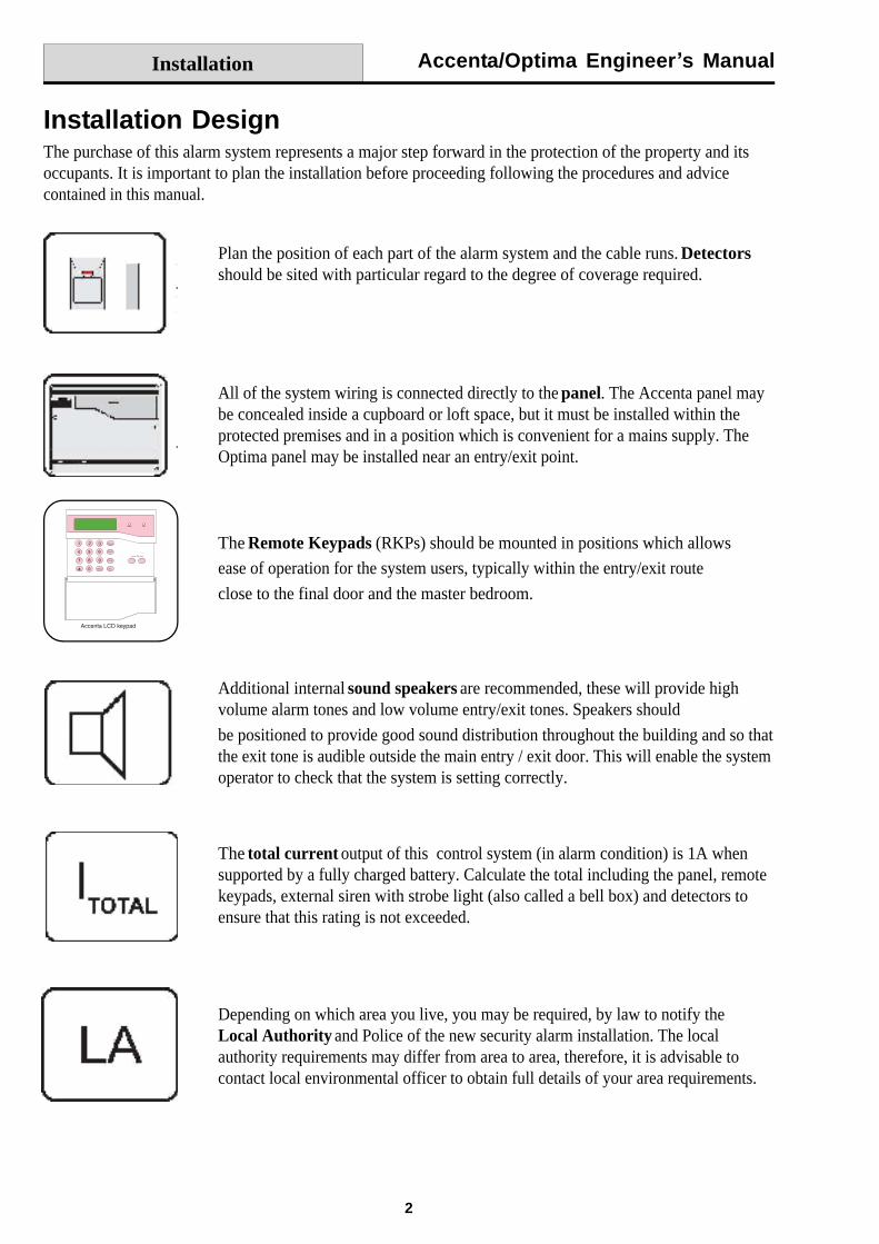
Installation DesignThe purchase of this alarm system represents a major step forward in the protection of the property and itsoccupants. It is important to plan the installation before proceeding following the procedures and advicecontained in this manual.
Plan the position of each part of the alarm system and the cable runs. Detectorsshould be sited with particular regard to the degree of coverage required.
All of the system wiring is connected directly to the panel. The Accenta panel maybe concealed inside a cupboard or loft space, but it must be installed within theprotected premises and in a position which is convenient for a mains supply. TheOptima panel may be installed near an entry/exit point.
The Remote Keypads (RKPs) should be mounted in positions which allows
ease of operation for the system users, typically within the entry/exit route
close to the final door and the master bedroom.
Additional internal sound speakers are recommended, these will provide highvolume alarm tones and low volume entry/exit tones. Speakers should
be positioned to provide good sound distribution throughout the building and so thatthe exit tone is audible outside the main entry / exit door. This will enable the systemoperator to check that the system is setting correctly.
The total current output of this control system (in alarm condition) is 1A whensupported by a fully charged battery. Calculate the total including the panel, remotekeypads, external siren with strobe light (also called a bell box) and detectors toensure that this rating is not exceeded.
Depending on which area you live, you may be required, by law to notify theLocal Authority and Police of the new security alarm installation. The localauthority requirements may differ from area to area, therefore, it is advisable tocontact local environmental officer to obtain full details of your area requirements.
Accenta/Optima Engineer s Manual
3
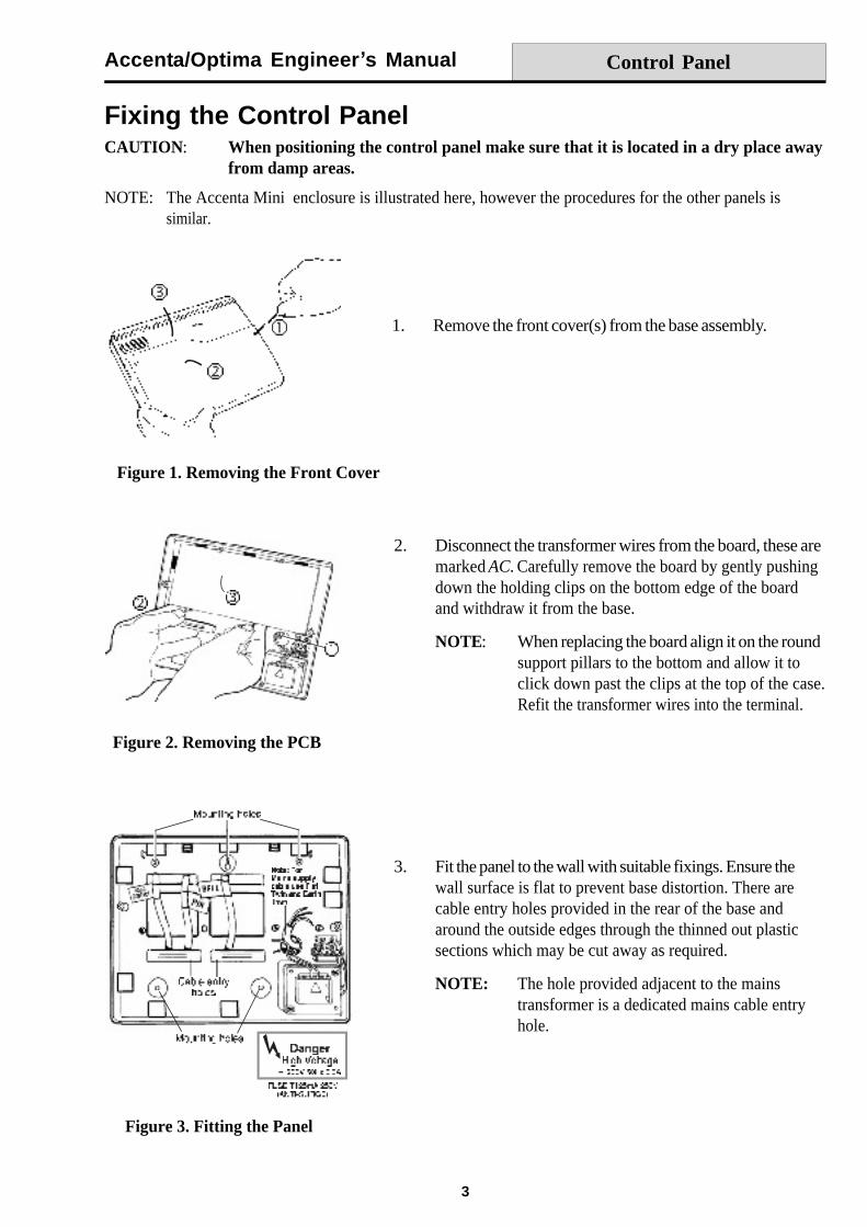
Fixing the Control PanelCAUTION: When positioning the control panel make sure that it is located in a dry place away
from damp areas.
NOTE: The Accenta Mini enclosure is illustrated here, however the procedures for the other panels issimilar.
Control Panel
2. Disconnect the transformer wires from the board, these aremarked AC. Carefully remove the board by gently pushingdown the holding clips on the bottom edge of the boardand withdraw it from the base.
NOTE: When replacing the board align it on the roundsupport pillars to the bottom and allow it toclick down past the clips at the top of the case.Refit the transformer wires into the terminal.
1. Remove the front cover(s) from the base assembly.
3. Fit the panel to the wall with suitable fixings. Ensure thewall surface is flat to prevent base distortion. There arecable entry holes provided in the rear of the base andaround the outside edges through the thinned out plasticsections which may be cut away as required.
NOTE: The hole provided adjacent to the mainstransformer is a dedicated mains cable entryhole.
Figure 1. Removing the Front Cover
Figure 2. Removing the PCB
Figure 3. Fitting the Panel
Accenta/Optima Engineer s Manual
4
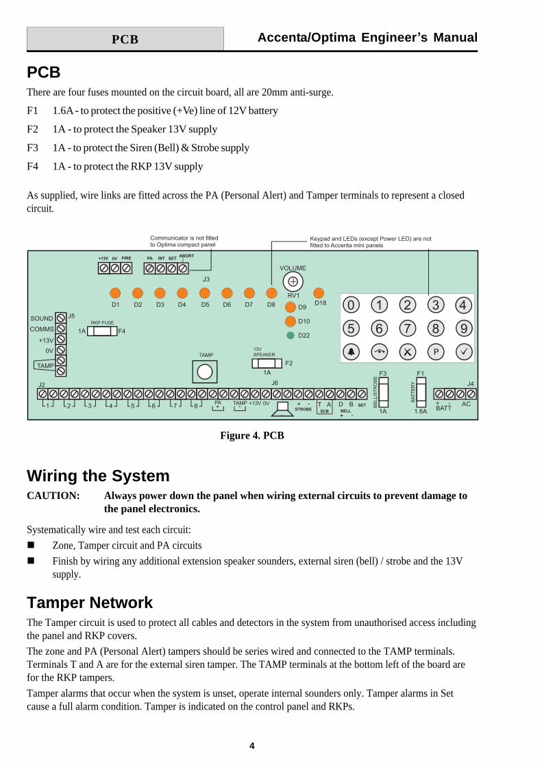
PCBThere are four fuses mounted on the circuit board, all are 20mm anti-surge.
F1 1.6A - to protect the positive (+Ve) line of 12V battery
F2 1A - to protect the Speaker 13V supply
F3 1A - to protect the Siren (Bell) & Strobe supply
F4 1A - to protect the RKP 13V supply
As supplied, wire links are fitted across the PA (Personal Alert) and Tamper terminals to represent a closedcircuit.
Wiring the SystemCAUTION: Always power down the panel when wiring external circuits to prevent damage to
the panel electronics.
Systematically wire and test each circuit:
Zone, Tamper circuit and PA circuits
Finish by wiring any additional extension speaker sounders, external siren (bell) / strobe and the 13Vsupply.
Tamper NetworkThe Tamper circuit is used to protect all cables and detectors in the system from unauthorised access includingthe panel and RKP covers.
The zone and PA (Personal Alert) tampers should be series wired and connected to the TAMP terminals.Terminals T and A are for the external siren tamper. The TAMP terminals at the bottom left of the board arefor the RKP tampers.
Tamper alarms that occur when the system is unset, operate internal sounders only. Tamper alarms in Setcause a full alarm condition. Tamper is indicated on the control panel and RKPs.
Figure 4. PCB
PCB
Accenta/Optima Engineer s Manual
5
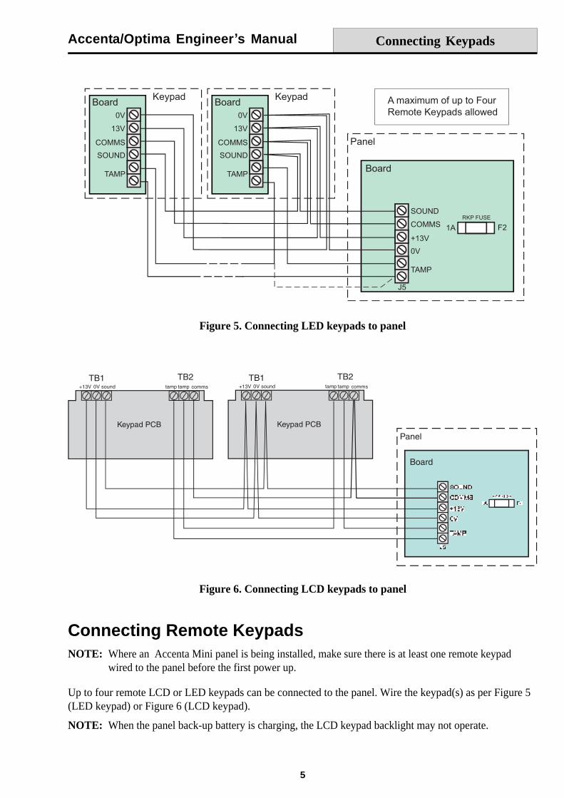
Figure 5. Connecting LED keypads to panel
Connecting Keypads
Connecting Remote KeypadsNOTE: Where an Accenta Mini panel is being installed, make sure there is at least one remote keypad
wired to the panel before the first power up.
Up to four remote LCD or LED keypads can be connected to the panel. Wire the keypad(s) as per Figure 5(LED keypad) or Figure 6 (LCD keypad).
NOTE: When the panel back-up battery is charging, the LCD keypad backlight may not operate.
Figure 6. Connecting LCD keypads to panel
Accenta/Optima Engineer s Manual
6
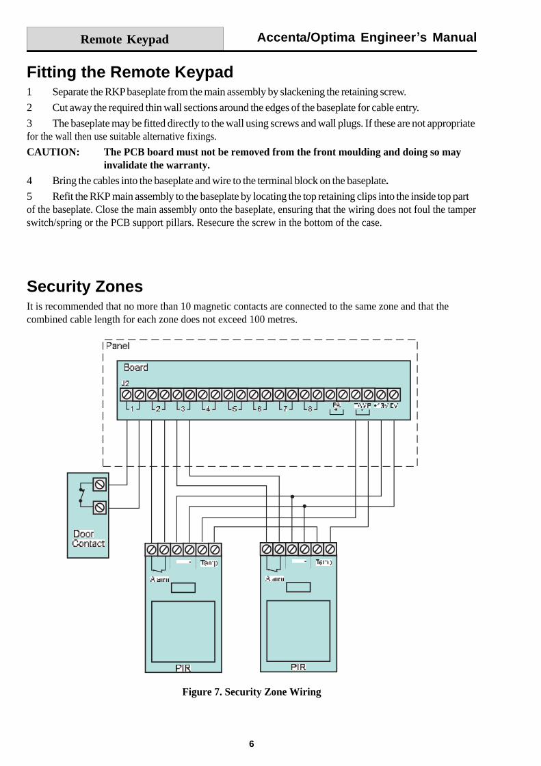
Security ZonesIt is recommended that no more than 10 magnetic contacts are connected to the same zone and that thecombined cable length for each zone does not exceed 100 metres.
Figure 7. Security Zone Wiring
Fitting the Remote Keypad1 Separate the RKP baseplate from the main assembly by slackening the retaining screw.
2 Cut away the required thin wall sections around the edges of the baseplate for cable entry.
3 The baseplate may be fitted directly to the wall using screws and wall plugs. If these are not appropriatefor the wall then use suitable alternative fixings.
CAUTION: The PCB board must not be removed from the front moulding and doing so mayinvalidate the warranty.
4 Bring the cables into the baseplate and wire to the terminal block on the baseplate.5 Refit the RKP main assembly to the baseplate by locating the top retaining clips into the inside top partof the baseplate. Close the main assembly onto the baseplate, ensuring that the wiring does not foul the tamperswitch/spring or the PCB support pillars. Resecure the screw in the bottom of the case.
Remote Keypad
Accenta/Optima Engineer s Manual
7
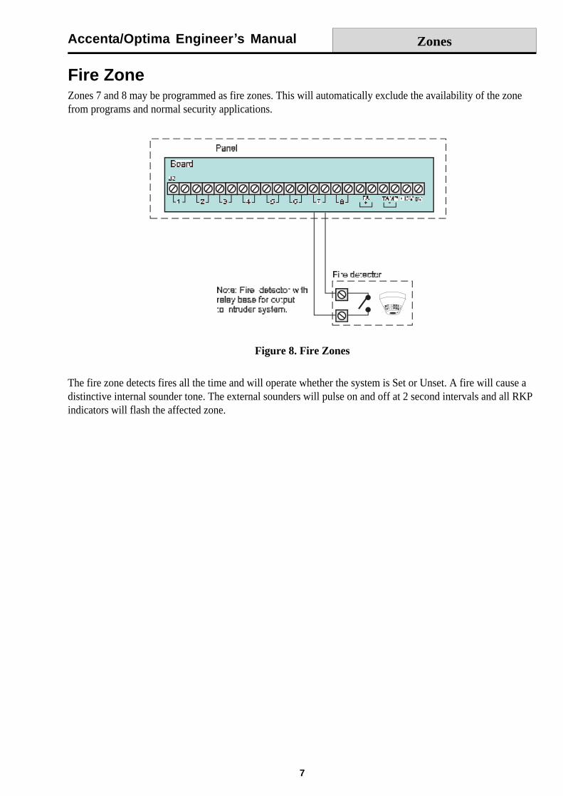
Fire ZoneZones 7 and 8 may be programmed as fire zones. This will automatically exclude the availability of the zonefrom programs and normal security applications.
Figure 8. Fire Zones
The fire zone detects fires all the time and will operate whether the system is Set or Unset. A fire will cause adistinctive internal sounder tone. The external sounders will pulse on and off at 2 second intervals and all RKPindicators will flash the affected zone.
Zones

Accenta/Optima Engineer s Manual
8
PA CircuitIt is recommended that no more than 10 Normally Closed type personal attack buttons may be wired in seriesand then connected to the PA circuit.Operational in Unset and Set, the PA circuit will cause a full alarm condition when activated. PA isindicated on the control panel or RKP.
PA buttons may be fitted near the front door or in a bedroom.
Figure 9. PA Circuit
Extension SpeakerExtension speakers may be connected to the loudspeaker terminals to produce high volume alarm tones andlow volume entry / exit / fault tones.
Up to two 16 ohm extension speakers may be wired across the speaker terminals. Mounted in convenientpositions within the installation the extension speakers will reproduce all of the alarm tones generated by thecontrol panel.
A control marked VOLUME may be used to adjust the low volume entry/exit tones to suit environmentalconditions.
Figure 10. Extension Speaker Wiring
PA Circuit
Accenta/Optima Engineer s Manual
9
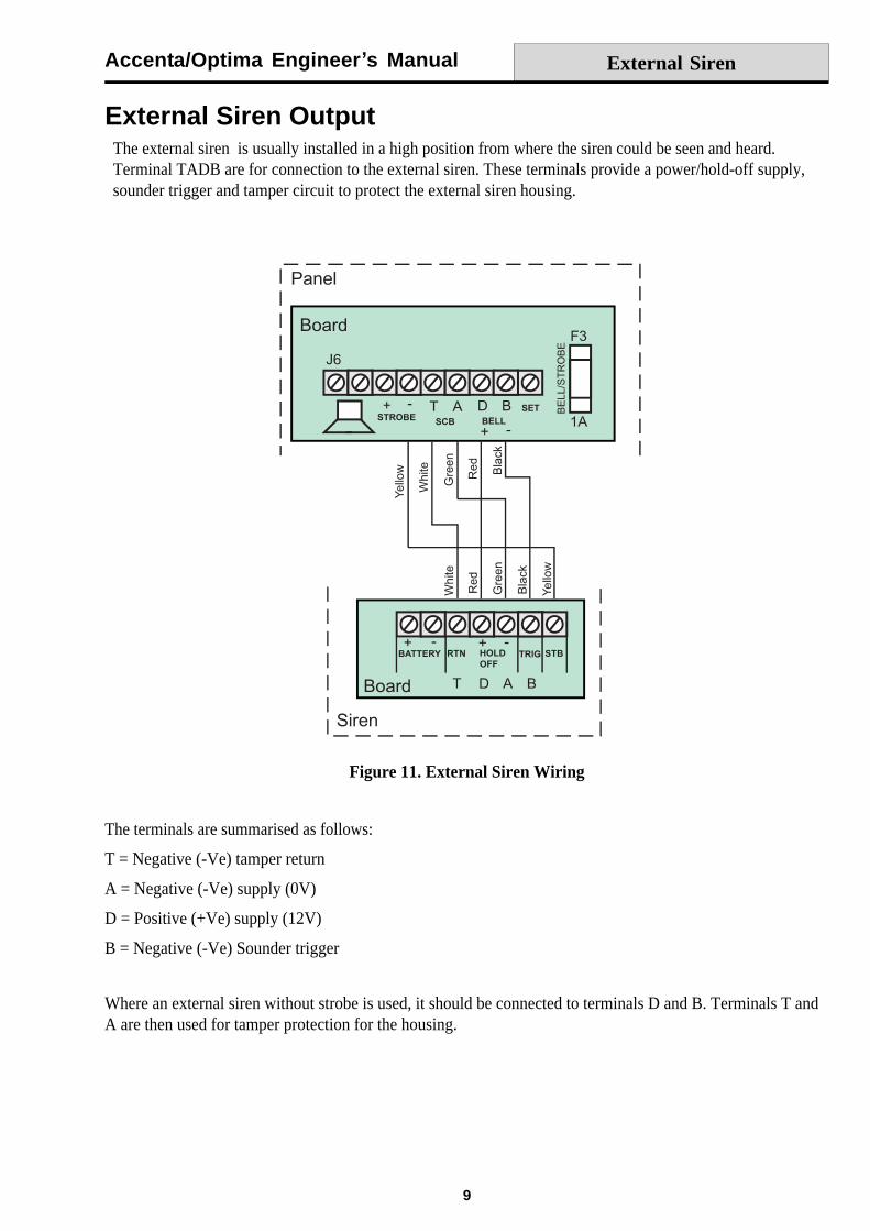
External Siren OutputThe external siren is usually installed in a high position from where the siren could be seen and heard.Terminal TADB are for connection to the external siren. These terminals provide a power/hold-off supply,sounder trigger and tamper circuit to protect the external siren housing.
Figure 11. External Siren Wiring
The terminals are summarised as follows:
T = Negative (-Ve) tamper return
A = Negative (-Ve) supply (0V)
D = Positive (+Ve) supply (12V)
B = Negative (-Ve) Sounder trigger
Where an external siren without strobe is used, it should be connected to terminals D and B. Terminals T andA are then used for tamper protection for the housing.
External Siren
Accenta/Optima Engineer s Manual
10
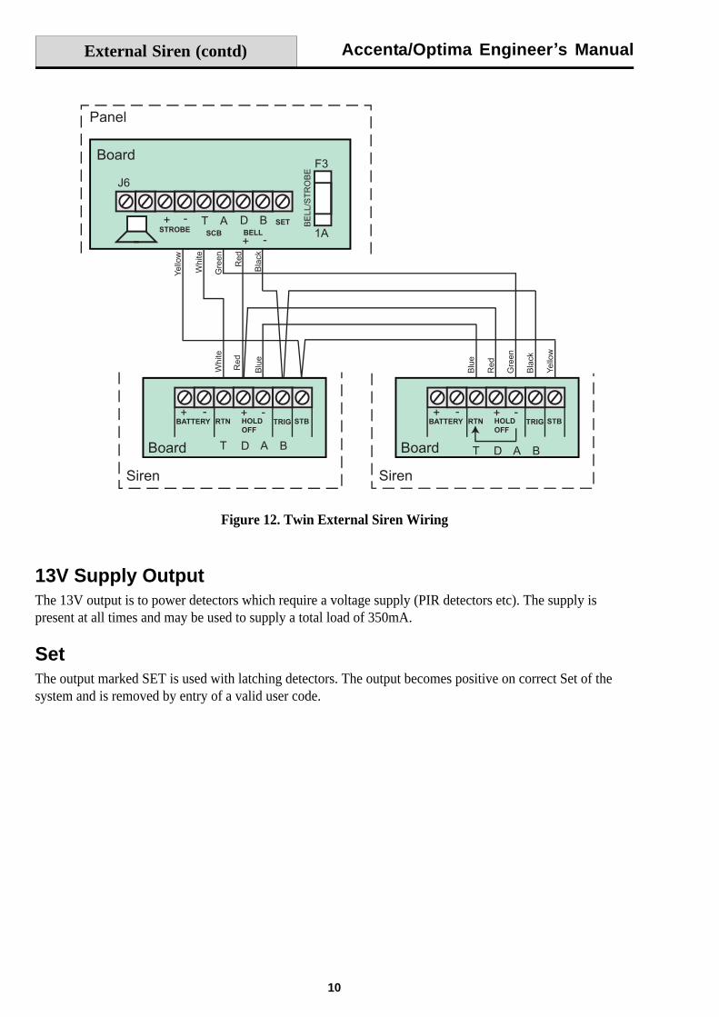
Figure 12. Twin External Siren Wiring
13V Supply OutputThe 13V output is to power detectors which require a voltage supply (PIR detectors etc). The supply ispresent at all times and may be used to supply a total load of 350mA.
SetThe output marked SET is used with latching detectors. The output becomes positive on correct Set of thesystem and is removed by entry of a valid user code.
External Siren (contd)
Accenta/Optima Engineer s Manual
11
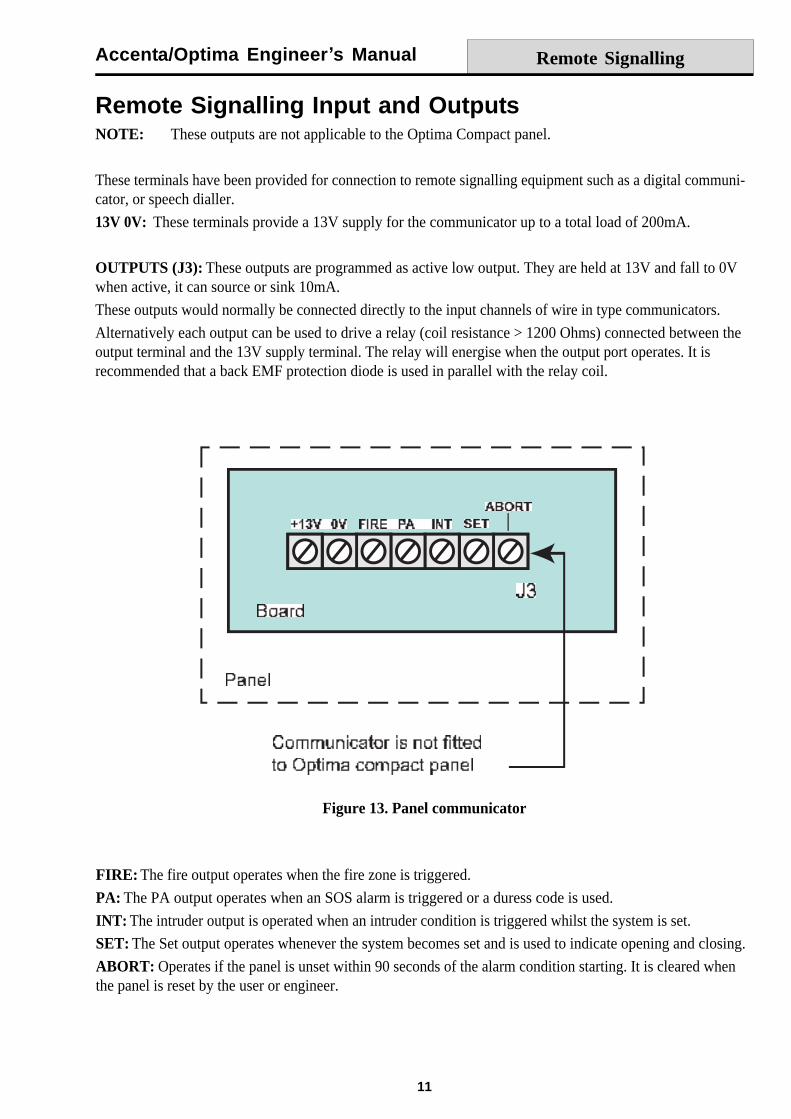
Remote Signalling Input and OutputsNOTE: These outputs are not applicable to the Optima Compact panel.
These terminals have been provided for connection to remote signalling equipment such as a digital communi-cator, or speech dialler.
13V 0V: These terminals provide a 13V supply for the communicator up to a total load of 200mA.
OUTPUTS (J3): These outputs are programmed as active low output. They are held at 13V and fall to 0Vwhen active, it can source or sink 10mA.
These outputs would normally be connected directly to the input channels of wire in type communicators.
Alternatively each output can be used to drive a relay (coil resistance > 1200 Ohms) connected between theoutput terminal and the 13V supply terminal. The relay will energise when the output port operates. It isrecommended that a back EMF protection diode is used in parallel with the relay coil.
FIRE: The fire output operates when the fire zone is triggered.
PA: The PA output operates when an SOS alarm is triggered or a duress code is used.
INT: The intruder output is operated when an intruder condition is triggered whilst the system is set.
SET: The Set output operates whenever the system becomes set and is used to indicate opening and closing.
ABORT: Operates if the panel is unset within 90 seconds of the alarm condition starting. It is cleared whenthe panel is reset by the user or engineer.
Figure 13. Panel communicator
Remote Signalling

Accenta/Optima Engineer s Manual
12
Important Notes1. Each output has been configured as active low.
2. Where the communicator is powered from an external source, not the panel and the outputs are beingused without relays, the panel and external power supply will require a common negative supply rail.
3. If the communicator is not fitted inside the panel and abort is being used, care should be taken to ensurethat the abort connection cannot be damaged or severed as this could cause the ARC to incorrectlyfilter an alarm signal.
4. It is very important that communicating systems are fully tested and that all signals are correctly receivedat the ARC when the system is installed and serviced.
Filtering of Intruder alarmsThe exact method of filtering should be decided according to the security services / keyholder requirementsand ARC procedures.
In general, the panels offer the following methods that could be used to filter an alarm.
Set/Unset A Set or Unset signal which is received by the ARC at around the same time as an intruder signalcan be used to filter the alarm.
Abort Output The abort output operates whenever a user code is entered to switch off an intruder alarmcondition. When an abort signal is received by ARC at or around the same time as an intruder signal, the alarmcan be filtered.
Restore of the Intruder Output The intruder alarm output is restored to 12V whenever a user code isentered to switch off an intruder alarm condition. Where an intruder alarm is shortly followed by a restore atthe ARC, this can be used to filter the alarm.
Remote Signalling (contd)
Accenta/Optima Engineer s Manual
13
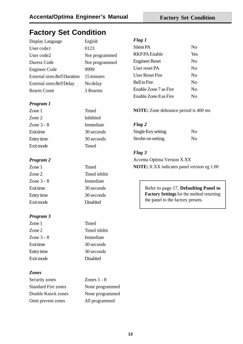
Factory Set ConditionDisplay Language English
User code1 0123
User code2 Not programmed
Duress Code Not programmed
Engineer Code 9999
External siren Bell Duration 15 minutes
External siren Bell Delay No delay
Rearm Count 3 Rearms
Program 1
Zone 1 Timed
Zone 2 Inhibited
Zone 3 - 8 Immediate
Exit time 30 seconds
Entry time 30 seconds
Exit mode Timed
Program 2
Zone 1 Timed
Zone 2 Timed inhibit
Zone 3 - 8 Immediate
Exit time 30 seconds
Entry time 30 seconds
Exit mode Disabled
Program 3
Zone 1 Timed
Zone 2 Timed inhibit
Zone 3 - 8 Immediate
Exit time 30 seconds
Entry time 30 seconds
Exit mode Disabled
Zones
Security zones Zones 1 - 8
Standard Fire zones None programmed
Double Knock zones None programmed
Omit prevent zones All programmed
Flag 1
Silent PA No
RKP PA Enable Yes
Engineer Reset No
User reset PA No
User Reset Fire No
Bell in Fire No
Enable Zone 7 as Fire No
Enable Zone 8 as Fire No
NOTE: Zone debounce period is 400 ms
Flag 2
Single Key setting No
Strobe on setting No
Flag 3
Accenta Optima Version X.XX
NOTE: X.XX indicates panel version eg 1.00
Factory Set Condition
Refer to page 17, Defaulting Panel toFactory Settings for the method returningthe panel to the factory presets.
Accenta/Optima Engineer s Manual
14
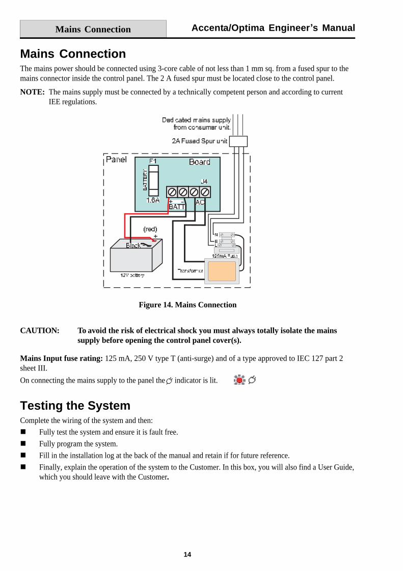
Mains ConnectionThe mains power should be connected using 3-core cable of not less than 1 mm sq. from a fused spur to themains connector inside the control panel. The 2 A fused spur must be located close to the control panel.
NOTE: The mains supply must be connected by a technically competent person and according to currentIEE regulations.
Figure 14. Mains Connection
CAUTION: To avoid the risk of electrical shock you must always totally isolate the mainssupply before opening the control panel cover(s).
Mains Input fuse rating: 125 mA, 250 V type T (anti-surge) and of a type approved to IEC 127 part 2sheet III.
On connecting the mains supply to the panel the indicator is lit.
Testing the SystemComplete the wiring of the system and then:
Fully test the system and ensure it is fault free.
Fully program the system.
Fill in the installation log at the back of the manual and retain if for future reference.
Finally, explain the operation of the system to the Customer. In this box, you will also find a User Guide,which you should leave with the Customer.
Mains Connection
Accenta/Optima Engineer s Manual
15
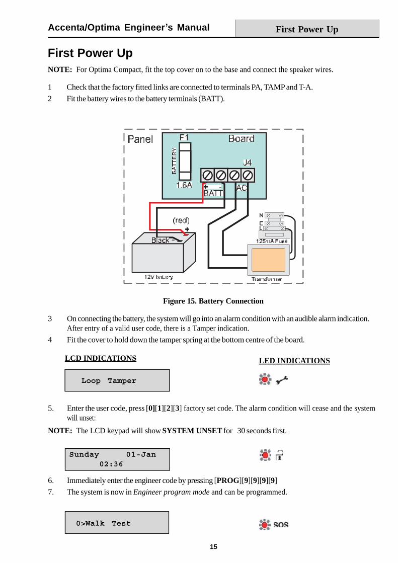
First Power UpNOTE: For Optima Compact, fit the top cover on to the base and connect the speaker wires.
1 Check that the factory fitted links are connected to terminals PA, TAMP and T-A.
2 Fit the battery wires to the battery terminals (BATT).
3 On connecting the battery, the system will go into an alarm condition with an audible alarm indication.After entry of a valid user code, there is a Tamper indication.
4 Fit the cover to hold down the tamper spring at the bottom centre of the board.
Figure 15. Battery Connection
First Power Up
LCD INDICATIONS LED INDICATIONS
5. Enter the user code, press [0][1][2][3] factory set code. The alarm condition will cease and the systemwill unset:
6. Immediately enter the engineer code by pressing [PROG][9][9][9][9]
7. The system is now in Engineer program mode and can be programmed.
NOTE: The LCD keypad will show SYSTEM UNSET for 30 seconds first.
Accenta/Optima Engineer s Manual
16
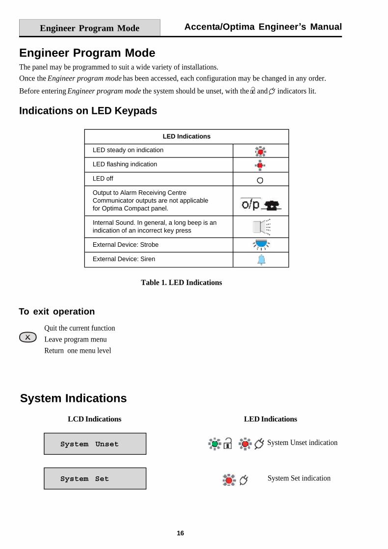
Engineer Program ModeThe panel may be programmed to suit a wide variety of installations.
Once the Engineer program mode has been accessed, each configuration may be changed in any order.
Before entering Engineer program mode the system should be unset, with the and indicators lit.
Indications on LED Keypads
Table 1. LED Indications
System Indications
System Set indication
LCD Indications LED Indications
Engineer Program Mode
System Unset indication
LED Indications
LED steady on indication
LED flashing indication
LED off
Output to Alarm Receiving CentreCommunicator outputs are not applicablefor Optima Compact panel.
Internal Sound. In general, a long beep is anindication of an incorrect key press
External Device: Strobe
External Device: Siren
To exit operation
Quit the current function
Leave program menu
Return one menu level
Accenta/Optima Engineer s Manual
17
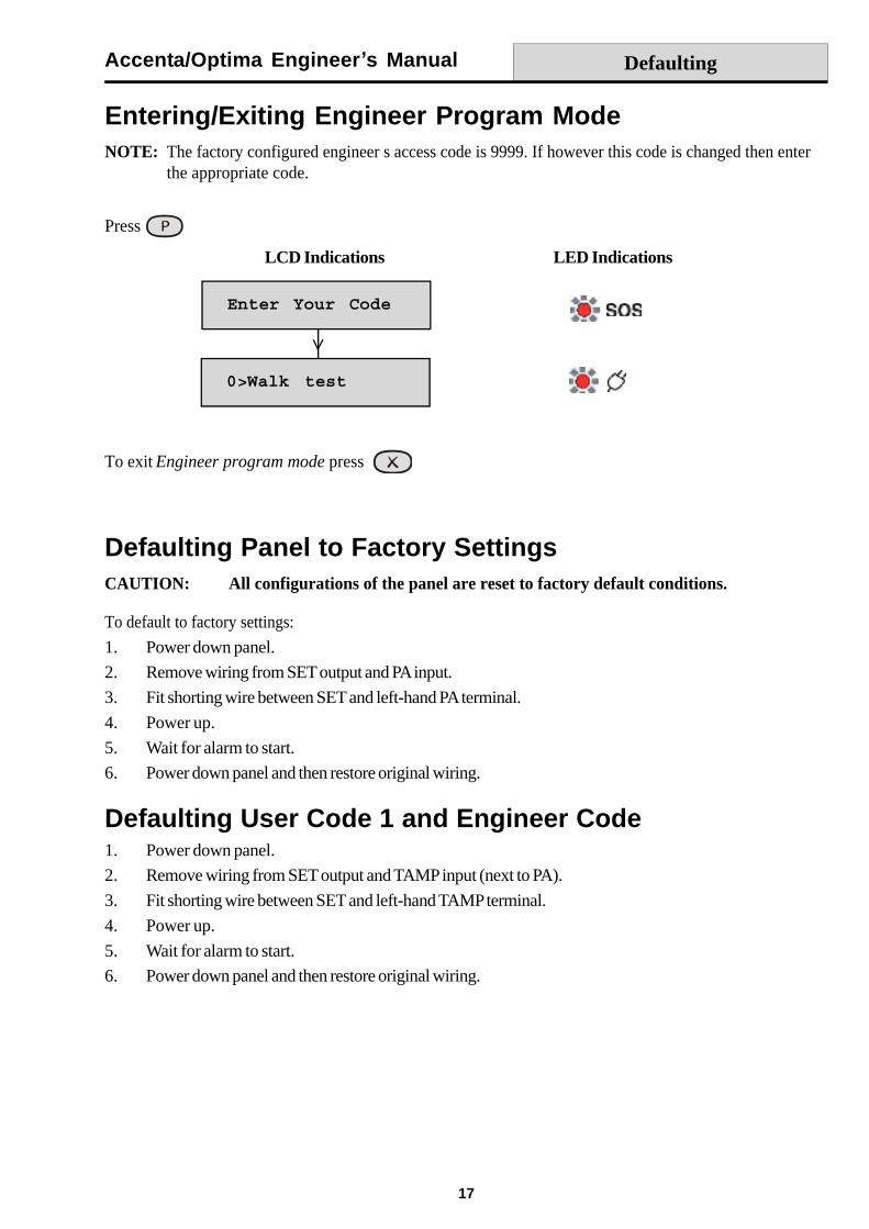
Entering/Exiting Engineer Program ModeNOTE: The factory configured engineer s access code is 9999. If however this code is changed then enter
the appropriate code.
LCD Indications LED Indications
Press
To exit Engineer program mode press
Defaulting Panel to Factory SettingsCAUTION: All configurations of the panel are reset to factory default conditions.
To default to factory settings:
1. Power down panel.
2. Remove wiring from SET output and PA input.
3. Fit shorting wire between SET and left-hand PA terminal.
4. Power up.
5. Wait for alarm to start.
6. Power down panel and then restore original wiring.
Defaulting User Code 1 and Engineer Code1. Power down panel.
2. Remove wiring from SET output and TAMP input (next to PA).
3. Fit shorting wire between SET and left-hand TAMP terminal.
4. Power up.
5. Wait for alarm to start.
6. Power down panel and then restore original wiring.
Defaulting
Accenta/Optima Engineer s Manual
18
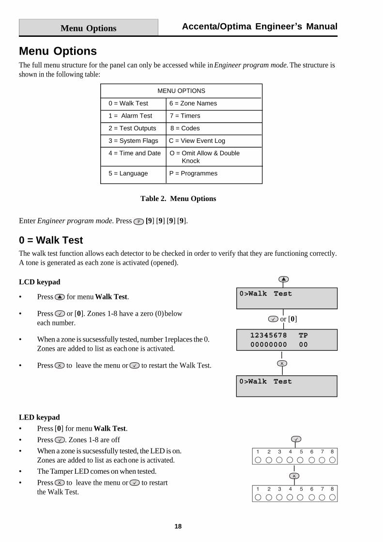
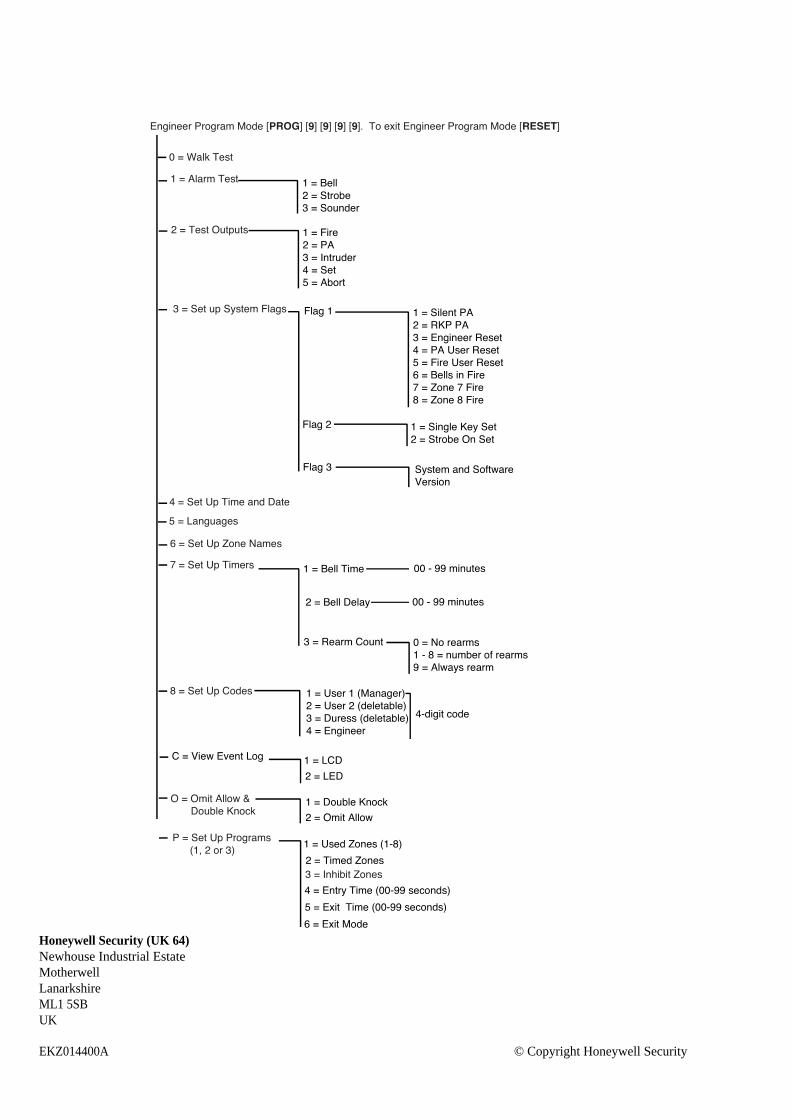
Menu OptionsThe full menu structure for the panel can only be accessed while in Engineer program mode. The structure isshown in the following table:
Table 2. Menu Options
Menu Options
Enter Engineer program mode. Press [9] [9] [9] [9].
0 = Walk TestThe walk test function allows each detector to be checked in order to verify that they are functioning correctly.A tone is generated as each zone is activated (opened).
LED keypadPress [0] for menu Walk Test.
Press . Zones 1-8 are off
When a zone is sucsessfully tested, the LED is on.Zones are added to list as eachone is activated.
The Tamper LED comes on when tested.
Press to leave the menu or to restartthe Walk Test.
LCD keypad
Press for menu Walk Test.
Press or [0]. Zones 1-8 have a zero (0)beloweach number.
When a zone is sucsessfully tested, number 1replaces the 0.Zones are added to list as eachone is activated.
Press to leave the menu or to restart the Walk Test.
MENU OPTIONS
0 = Walk Test 6 = Zone Names
1 = Alarm Test 7 = Timers
2 = Test Outputs 8 = Codes
3 = System Flags C = View Event Log
4 = Time and Date O = Omit Allow & Double Knock
5 = Language P = Programmes
or [0]
Accenta/Optima Engineer s Manual
19
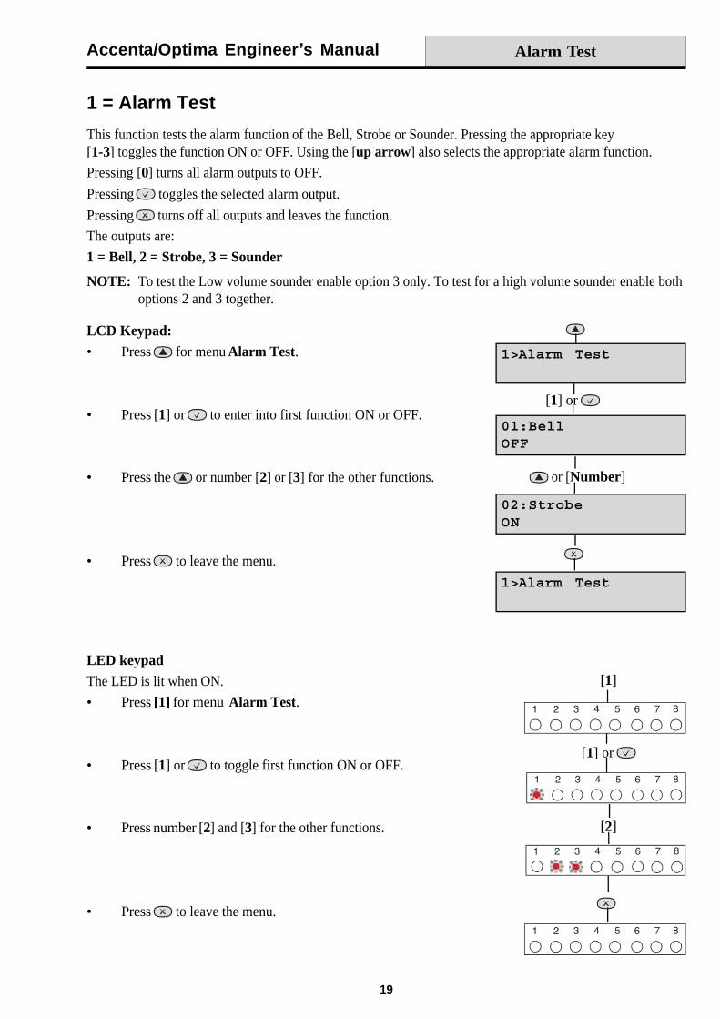
1 = Alarm Test
This function tests the alarm function of the Bell, Strobe or Sounder. Pressing the appropriate key[1-3] toggles the function ON or OFF. Using the [up arrow] also selects the appropriate alarm function.
Pressing [0] turns all alarm outputs to OFF.
Pressing toggles the selected alarm output.
Pressing turns off all outputs and leaves the function.
The outputs are:
1 = Bell, 2 = Strobe, 3 = Sounder
NOTE: To test the Low volume sounder enable option 3 only. To test for a high volume sounder enable bothoptions 2 and 3 together.
LCD Keypad:Press for menu Alarm Test.
Press [1] or to enter into first function ON or OFF.
Press the or number [2] or [3] for the other functions.
Press to leave the menu.
LED keypadThe LED is lit when ON.
Press [1] for menu Alarm Test.
Press [1] or to toggle first function ON or OFF.
Press number [2] and [3] for the other functions.
Press to leave the menu.
Alarm Test
[1] or
or [Number]
[1]
[1] or
[2]
Accenta/Optima Engineer s Manual
20
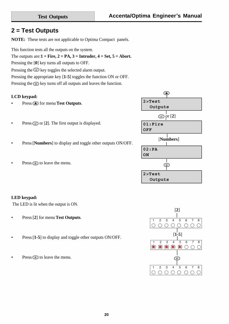
2 = Test OutputsNOTE: These tests are not applicable to Optima Compact panels.
This function tests all the outputs on the system.
The outputs are:1 = Fire, 2 = PA, 3 = Intruder, 4 = Set, 5 = Abort.Pressing the [0] key turns all outputs to OFF.
Pressing the key toggles the selected alarm output.
Pressing the appropriate key [1-5] toggles the function ON or OFF.
Pressing the key turns off all outputs and leaves the function.
LCD keypad:
Press for menu Test Outputs.
Press or [2]. The first output is displayed.
Press [Numbers] to display and toggle other outputs ON/OFF.
Press to leave the menu.
LED keypad: The LED is lit when the output is ON.
Press [2] for menu Test Outputs.
Press [1-5] to display and toggle other outputs ON/OFF.
Press to leave the menu.
Test Outputs
or [2]
[Numbers]
[2]
[1-5]
Accenta/Optima Engineer s Manual
21
Test Outputs
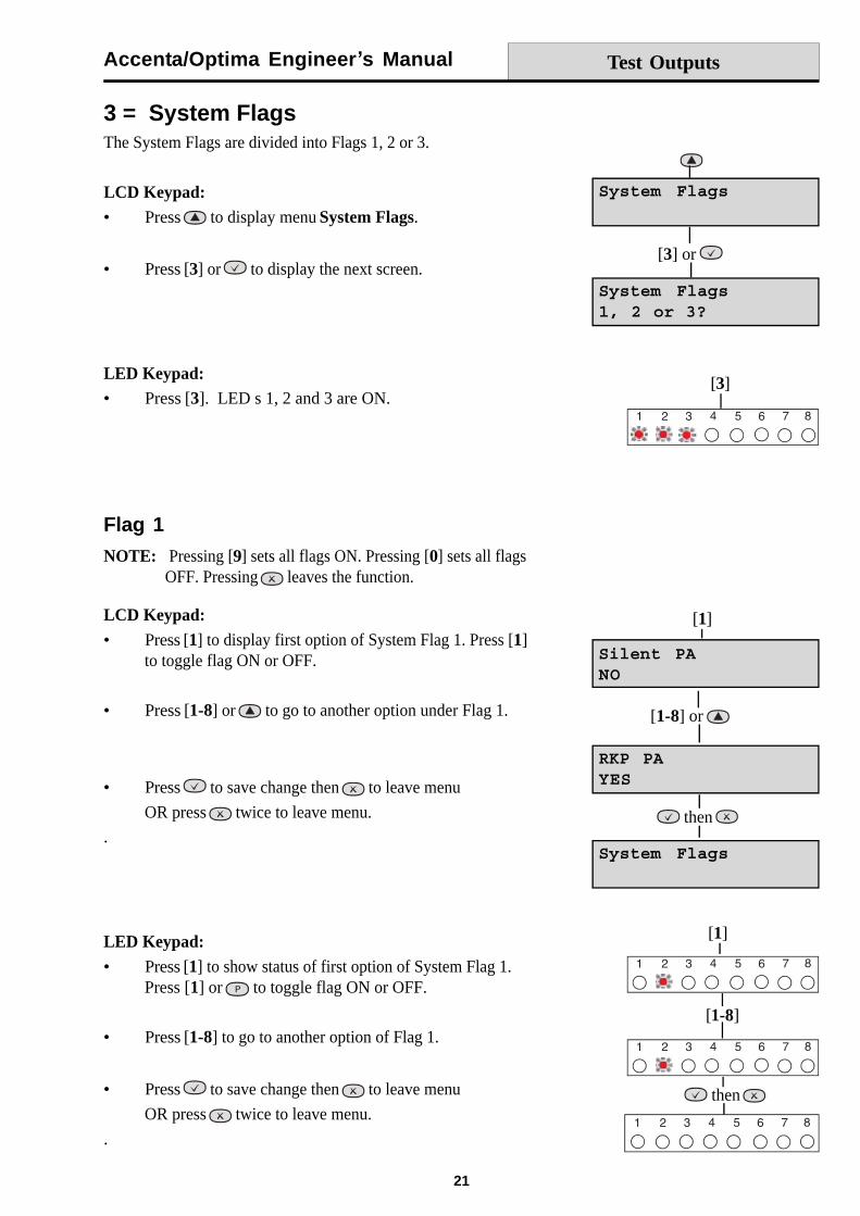
3 = System FlagsThe System Flags are divided into Flags 1, 2 or 3.
LCD Keypad:Press to display menu System Flags.
Press [3] or to display the next screen.
LED Keypad:Press [3]. LED s 1, 2 and 3 are ON.
Flag 1
NOTE: Pressing [9] sets all flags ON. Pressing [0] sets all flagsOFF. Pressing leaves the function.
LCD Keypad:Press [1] to display first option of System Flag 1. Press [1]to toggle flag ON or OFF.
Press [1-8] or to go to another option under Flag 1.
Press to save change then to leave menu
OR press twice to leave menu.
.
LED Keypad:Press [1] to show status of first option of System Flag 1.Press [1] or to toggle flag ON or OFF.
Press [1-8] to go to another option of Flag 1.
Press to save change then to leave menu
OR press twice to leave menu.
.
[3]
[3] or
[1]
[1-8] or
then
[1]
[1-8]
then

Accenta/Optima Engineer s Manual
22
System Flags
Flag 1 - OptionsThere are eight options under Flag1 which are described below:
1 = Silent PAWhen this flag is set to ON, operating SOS will cause a silent alarm. Pressing [1] toggles the flag ON or OFF.
2 = RKP PAWhen this flag is set to ON, the keypad SOS keys are enabled. Pressing [2] toggles the flag ON or OFF.
3 = Engineer ResetWhen this flag is set to ON, an engineer code must be entered to reset the system after Tamper, SOS or Firealarm. When the flag is set to OFF the system can be reset by the user. Pressing the [3] key toggles the flagON or OFF.
4 = PA User Reset
When this flag is set to ON, it permits the user to reset the system after an SOS alarm, by pressing . Theuser can reset the system even if the Engineer Reset flag is set to ON. Pressing [4] toggles the flag ON orOFF.
5 = Fire User Reset
When this flag is set to ON, it permits the user to reset the system after a Fire alarm by pressing . The usercan reset the system even if the Engineer Reset flag is set to ON. Pressing [5] toggles the flag ON or OFF.
6 = Bells in FireWhen this flag is set to ON, the external siren Bell box will sound two seconds On/two second Off during thefire alarm. Pressing [6] toggles the flag ON or OFF.
7 = Zone 7 FireWhen this flag is set to ON it permits zone 7 to be used as a Fire zone. Pressing [7] toggles the flag ON orOFF.
8 = Zone 8 FireWhen this flag is set to ON it permits zone 8 to be used as a Fire zone. Pressing [8] toggles the flag ON orOFF.
Accenta/Optima Engineer s Manual
23
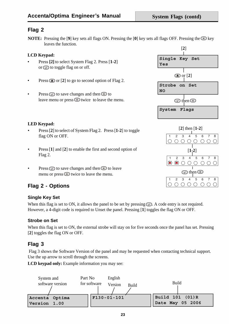
Flag 2
NOTE: Pressing the [9] key sets all flags ON. Pressing the [0] key sets all flags OFF. Pressing the keyleaves the function.
System andsoftware version
Part Nofor software
English
Version Build Build
Flag 2 - Options
Single Key SetWhen this flag is set to ON, it allows the panel to be set by pressing . A code entry is not required.However, a 4-digit code is required to Unset the panel. Pressing [1] toggles the flag ON or OFF.
Strobe on SetWhen this flag is set to ON, the external strobe will stay on for five seconds once the panel has set. Pressing[2] toggles the flag ON or OFF.
Flag 3 Flag 3 shows the Software Version of the panel and may be requested when contacting technical support.Use the up arrow to scroll through the screens.
LCD keypad only: Example information you may see:
LCD Keypad:
Press [2] to select System Flag 2. Press [1-2]or to toggle flag on or off.
Press or [2] to go to second option of Flag 2.
Press to save changes and then toleave menu or press
twice to leave the menu.
LED Keypad:Press [2] to select of System Flag 2. Press [1-2] to toggleflag ON or OFF.
Press [1] and [2] to enable the first and second option ofFlag 2.
Press to save changes and then to leavemenu or press twice to leave the menu.
System Flags (contd)
[2]
or [2]
then
[2] then [1-2]
[1-2]
then
Accenta/Optima Engineer s Manual
24
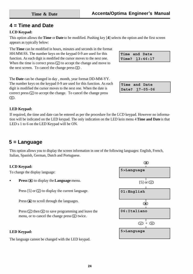
4 = Time and DateLCD Keypad:This option allows the Time or Date to be modified. Pushing key [4] selects the option and the first screenappears as typically below:
The Time can be modified in hours, minutes and seconds in the formatHH:MM:SS. The number keys on the keypad 0-9 are used for thisfunction. As each digit is modified the cursor moves to the next one.When the time is correct press to accept the change and move tothe next screen. To cancel the change press .
The Date can be changed in day , month, year format DD-MM-YY.The number keys on the keypad 0-9 are used for this function. As eachdigit is modified the cursor moves to the next one. When the date iscorrect press to accept the change. To cancel the change press
.
Time & Date
LED Keypad:If required, the time and date can be entered as per the procedure for the LCD keypad. However no informa-tion will be indicated on the LED keypad. The only indication on the LED kein menu 4 Time and Date is thatLED s 1 to 6 on the LED Keypad will be ON.
5 = Language
This option allows you to display the screen information in one of the following languages: English, French,Italian, Spanish, German, Dutch and Portuguese.
LCD Keypad:To change the display language:
Press to display the Language menu.
Press [5] or to display the current language.
Press to scroll through the languages.
Press then to save programming and leave themenu, or to cancel the change press twice.
LED Keypad:
The language cannot be changed with the LED keypad.
[5] or
+
Accenta/Optima Engineer s Manual
25
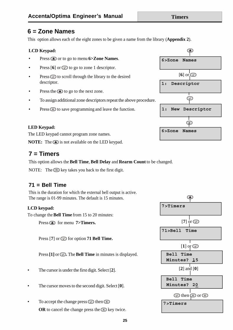
6 = Zone NamesThis option allows each of the eight zones to be given a name from the library (Appendix 2).
LCD Keypad:
Press or to go to menu 6>Zone Names.
Press [6] or to go to zone 1 descriptor.
Press to scroll through the library to the desireddescriptor.
Press the to go to the next zone.
To assign additional zone descriptors repeat the above procedure.
Press to save programming and leave the function.
LED Keypad:The LED keypad cannot program zone names.
NOTE: The is not available on the LED keypad.
Timers
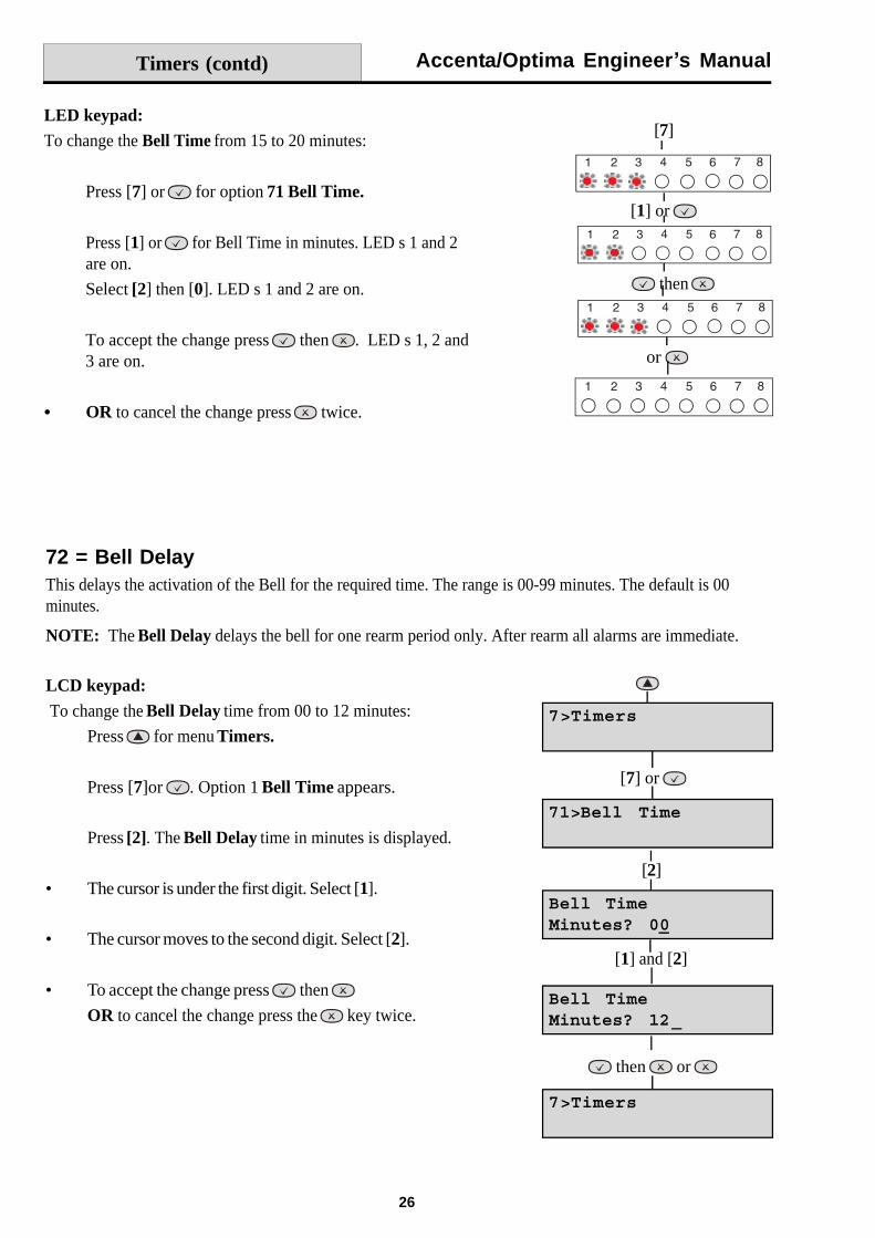
LCD keypad:To change the Bell Time from 15 to 20 minutes:
Press for menu 7>Timers.
Press [7] or for option 71 Bell Time.
Press [1] or . The Bell Time in minutes is displayed.
The cursor is under the first digit. Select [2].
The cursor moves to the second digit. Select [0].
To accept the change press then
OR to cancel the change press the key twice.
7 = TimersThis option allows the Bell Time, Bell Delay and Rearm Count to be changed.
NOTE: The key takes you back to the first digit.
71 = Bell TimeThis is the duration for which the external bell output is active.The range is 01-99 minutes. The default is 15 minutes.
[7] or
then or
[2] and [0]
[6] or
[1] or
Accenta/Optima Engineer s Manual
26
Timers (contd)
LCD keypad: To change the Bell Delay time from 00 to 12 minutes:
Press for menu Timers.
Press [7]or . Option 1 Bell Time appears.
Press [2]. The Bell Delay time in minutes is displayed.
The cursor is under the first digit. Select [1].
The cursor moves to the second digit. Select [2].
To accept the change press then
OR to cancel the change press the key twice.
72 = Bell DelayThis delays the activation of the Bell for the required time. The range is 00-99 minutes. The default is 00minutes.
NOTE: The Bell Delay delays the bell for one rearm period only. After rearm all alarms are immediate.
[2]
[7] or
then or
[1] and [2]
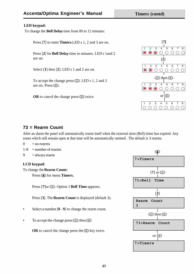
LED keypad:To change the Bell Time from 15 to 20 minutes:
Press [7] or for option 71 Bell Time.
Press [1] or for Bell Time in minutes. LED s 1 and 2are on. Select [2] then [0]. LED s 1 and 2 are on.
To accept the change press then . LED s 1, 2 and3 are on.
OR to cancel the change press twice.
[7]
or
[1] or
then
Accenta/Optima Engineer s Manual
27
Timers (contd)
LED keypad:To change the Bell Delay time from 00 to 12 minutes:
Press [7] to enter Timers.LED s 1, 2 and 3 are on.
Press [2] for Bell Delay time in minutes. LED s 1and 2are on.
Select [1] then [2]. LED s 1 and 2 are on.
To accept the change press . LED s 1, 2 and 3are on. Press .
OR to cancel the change press twice.
[7]
then
[2]
or
73 = Rearm CountAfter an alarm the panel will automatically rearm itself when the external siren (Bell) timer has expired. Anyzones which still remain open at that time will be automatically omitted . The default is 3 rearms.
0 = no rearms
1-8 = number of rearms
9 = always rearm
LCD keypad:To change the Rearm Count:
Press for menu Timers.
Press [7]or . Option 1 Bell Time appears.
Press [3]. The Rearm Count is displayed (default 3).
Select a number [0 - 9] to change the rearm count.
To accept the change press then
OR to cancel the change press the key twice.
[3]
[7] or
or
then
Accenta/Optima Engineer s Manual
28
8 = CodesThere are four codes used in the system, all are 4 digit and can be set to any number from 0000 to 9999. Theaccess codes ensure that only authorised users can operate the system.
User 1 and 2 codes
The user 1 and user 2 codes have the same operation for testing, Setting and Unsetting, but user 1 code whichis usually considered to be the Manager s code has the authority to add, change or delete the user 2 code andduress code.
Duress code
Should be used in a hold up situation where there is pressure to Set or Unset the system. Entry of the codewill allow the system to work normally but also generate a silent SOS type alarm by operating the PA commu-nicator output. The duress code is not applicable for Optima Compact system.
Engineer code
Accesses the Engineer program mode to allow the system to be programmed. The engineer code will not setor unset the system.
If configured the Engineer s code can be used to reset the system after an alarm.
NOTE: Entering an invalid user code will operate the code tamper. After 17 incorrect keypushes a full alarmcondition will be generated.
Codes (contd)
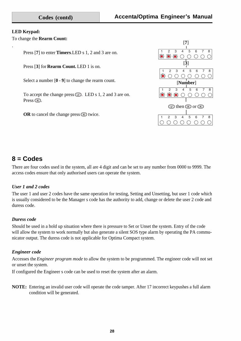
LED Keypad:To change the Rearm Count:.
Press [7] to enter Timers.LED s 1, 2 and 3 are on.
Press [3] for Rearm Count. LED 1 is on.
Select a number [0 - 9] to change the rearm count.
To accept the change press . LED s 1, 2 and 3 are on.Press .
OR to cancel the change press twice.
[7]
then or
[3]
[Number]
Accenta/Optima Engineer s Manual
29
Codes (contd)
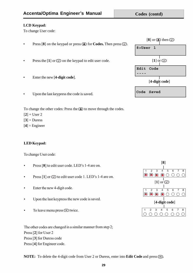
To change the other codes: Press the to move through the codes.
[2] = User 2
[3] = Duress
[4] = Engineer
LCD Keypad:To change User code:
Press [8] on the keypad or press for Codes. Then press .
Press the [1] or on the keypad to edit user code.
Enter the new [4-digit code].
Upon the last keypress the code is saved.
[8] or then
[1] or
[4-digit code]
NOTE: To delete the 4-digit code from User 2 or Duress, enter into Edit Code and press .
[8]
[1] or
[4-digit code]
Accenta/Optima Engineer s Manual
30
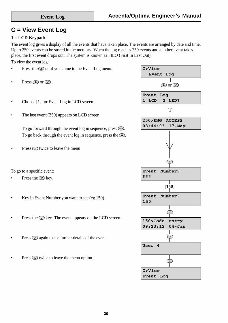
C = View Event Log1 = LCD Keypad:The event log gives a display of all the events that have taken place. The events are arranged by date and time.Up to 250 events can be stored in the memory. When the log reaches 250 events and another event takesplace, the first event drops out. The system is known as FILO (First In Last Out).
To view the event log:
Press the until you come to the Event Log menu.
Press or .
Choose [1] for Event Log in LCD screen.
The last event (250) appears on LCD screen.
To go forward through the event log in sequence, press .
To go back through the event log in sequence, press the .
Press twice to leave the menu
To go to a specific event:
Press the key.
Key in Event Number you want to see (eg 150).
Press the key. The event appears on the LCD screen.
Press again to see further details of the event.
Press twice to leave the menu option.
Event Log
or
[1]
[150]
Accenta/Optima Engineer s Manual
31
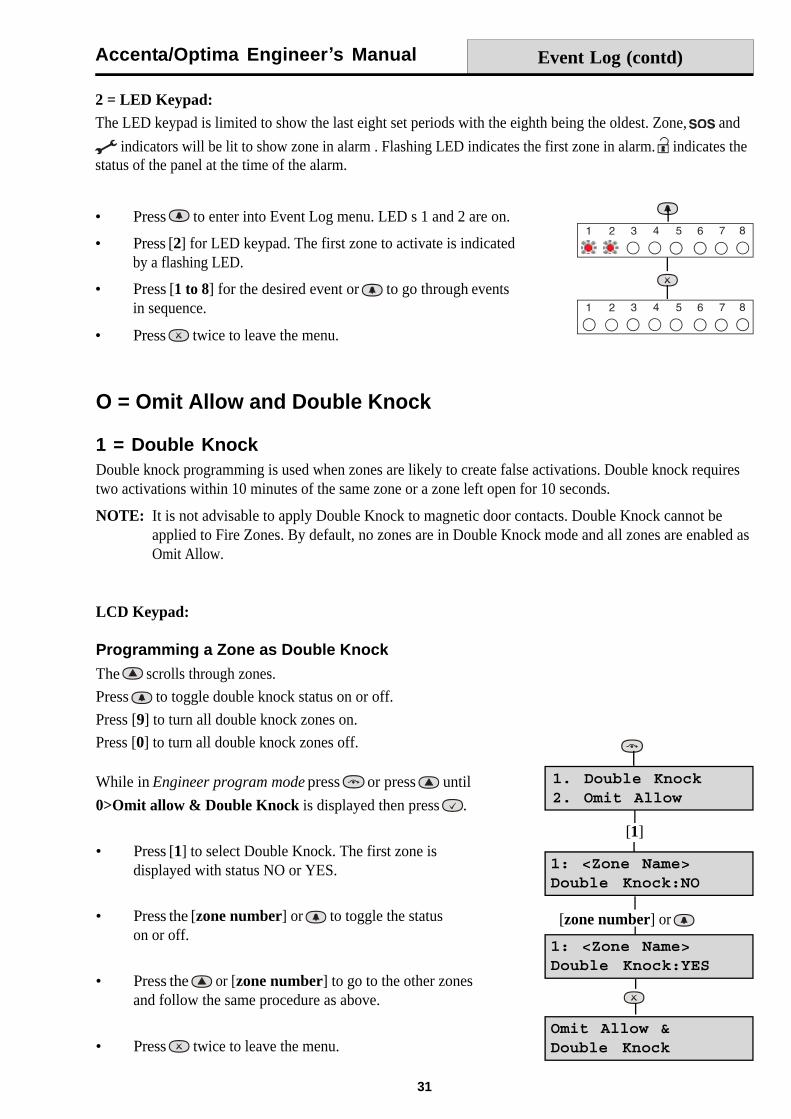
2 = LED Keypad:The LED keypad is limited to show the last eight set periods with the eighth being the oldest. Zone, and
indicators will be lit to show zone in alarm . Flashing LED indicates the first zone in alarm. indicates thestatus of the panel at the time of the alarm.
O = Omit Allow and Double Knock
1 = Double KnockDouble knock programming is used when zones are likely to create false activations. Double knock requirestwo activations within 10 minutes of the same zone or a zone left open for 10 seconds.
NOTE: It is not advisable to apply Double Knock to magnetic door contacts. Double Knock cannot beapplied to Fire Zones. By default, no zones are in Double Knock mode and all zones are enabled asOmit Allow.
LCD Keypad:
Programming a Zone as Double Knock
The scrolls through zones.
Press to toggle double knock status on or off.
Press [9] to turn all double knock zones on.
Press [0] to turn all double knock zones off.
Press to enter into Event Log menu. LED s 1 and 2 are on.
Press [2] for LED keypad. The first zone to activate is indicatedby a flashing LED.
Press [1 to 8] for the desired event or to go through eventsin sequence.
Press twice to leave the menu.
While in Engineer program mode press or press until
0>Omit allow & Double Knock is displayed then press .
Press [1] to select Double Knock. The first zone isdisplayed with status NO or YES.
Press the [zone number] or to toggle the statuson or off.
Press the or [zone number] to go to the other zonesand follow the same procedure as above.
Press twice to leave the menu.
Event Log (contd)
[1]
[zone number] or
Accenta/Optima Engineer s Manual
32
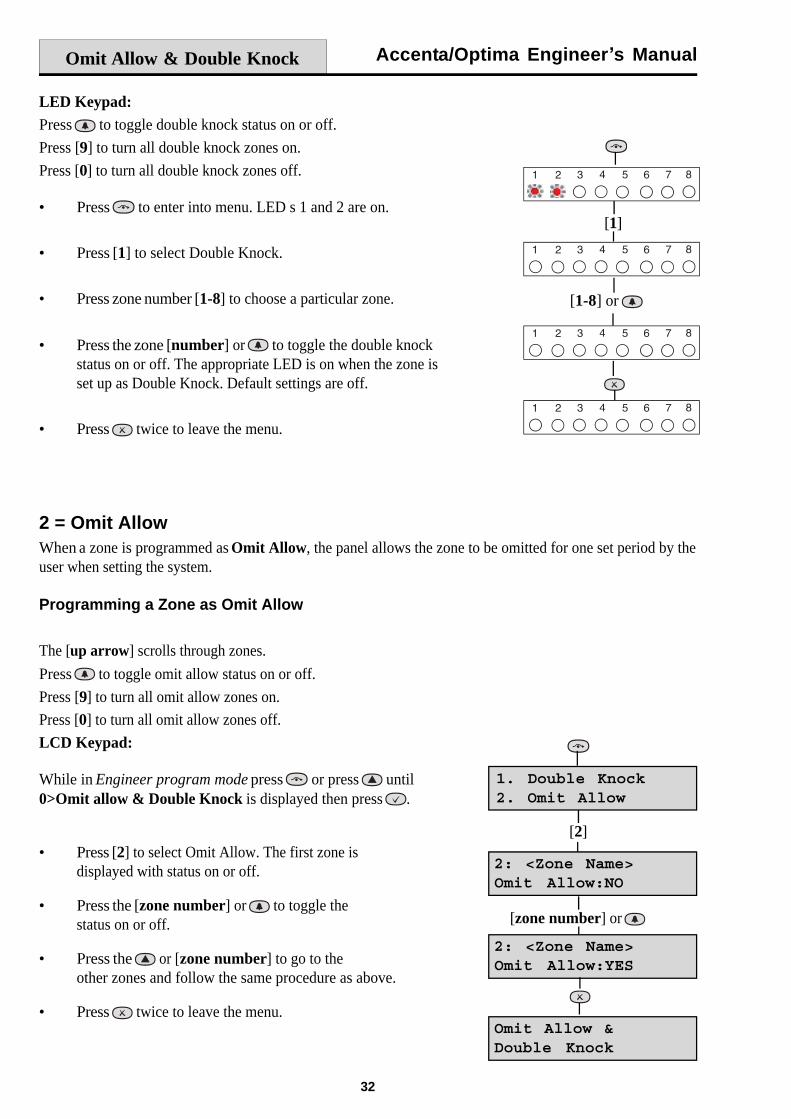
LED Keypad:Press to toggle double knock status on or off.
Press [9] to turn all double knock zones on.
Press [0] to turn all double knock zones off.
Press to enter into menu. LED s 1 and 2 are on.
Press [1] to select Double Knock.
Press zone number [1-8] to choose a particular zone.
Press the zone [number] or to toggle the double knockstatus on or off. The appropriate LED is on when the zone isset up as Double Knock. Default settings are off.
Press twice to leave the menu.
2 = Omit AllowWhen a zone is programmed as Omit Allow, the panel allows the zone to be omitted for one set period by theuser when setting the system.
Programming a Zone as Omit Allow
The [up arrow] scrolls through zones.
Press to toggle omit allow status on or off.
Press [9] to turn all omit allow zones on.
Press [0] to turn all omit allow zones off.
LCD Keypad:
While in Engineer program mode press or press until0>Omit allow & Double Knock is displayed then press .
Press [2] to select Omit Allow. The first zone isdisplayed with status on or off.
Press the [zone number] or to toggle thestatus on or off.
Press the or [zone number] to go to theother zones and follow the same procedure as above.
Press twice to leave the menu.
Omit Allow & Double Knock
[1]
[1-8] or
[2]
[zone number] or
Accenta/Optima Engineer s Manual
33
Omit Allow & Double Knock
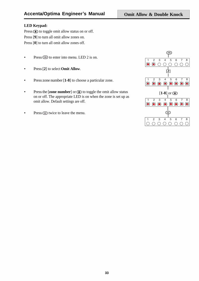
LED Keypad:Press to toggle omit allow status on or off.
Press [9] to turn all omit allow zones on.
Press [0] to turn all omit allow zones off.
Press to enter into menu. LED 2 is on.
Press [2] to select Omit Allow.
Press zone number [1-8] to choose a particular zone.
Press the [zone number] or to toggle the omit allow statuson or off. The appropriate LED is on when the zone is set up asomit allow. Default settings are off.
Press twice to leave the menu.
[2]
[1-8] or
Accenta/Optima Engineer s Manual
34
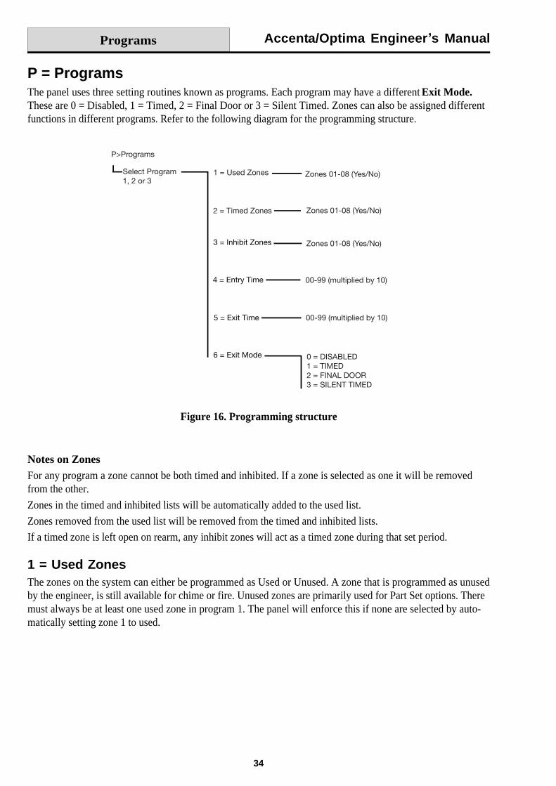
P = ProgramsThe panel uses three setting routines known as programs. Each program may have a different Exit Mode.These are 0 = Disabled, 1 = Timed, 2 = Final Door or 3 = Silent Timed. Zones can also be assigned differentfunctions in different programs. Refer to the following diagram for the programming structure.
Figure 16. Programming structure
Programs
Notes on ZonesFor any program a zone cannot be both timed and inhibited. If a zone is selected as one it will be removedfrom the other.
Zones in the timed and inhibited lists will be automatically added to the used list.
Zones removed from the used list will be removed from the timed and inhibited lists.
If a timed zone is left open on rearm, any inhibit zones will act as a timed zone during that set period.
1 = Used ZonesThe zones on the system can either be programmed as Used or Unused. A zone that is programmed as unusedby the engineer, is still available for chime or fire. Unused zones are primarily used for Part Set options. Theremust always be at least one used zone in program 1. The panel will enforce this if none are selected by auto-matically setting zone 1 to used.
Accenta/Optima Engineer s Manual
35
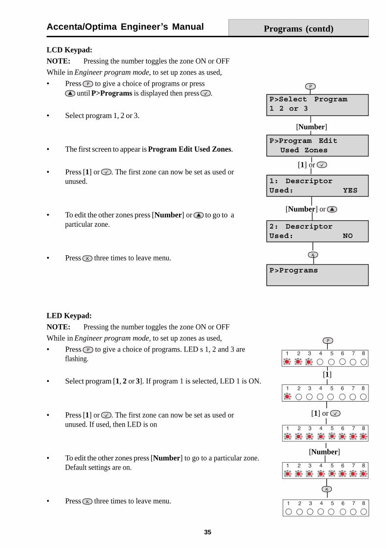
LCD Keypad:NOTE: Pressing the number toggles the zone ON or OFF
While in Engineer program mode, to set up zones as used,
Press to give a choice of programs or press until P>Programs is displayed then press .
Select program 1, 2 or 3.
The first screen to appear is Program Edit Used Zones.
Press [1] or . The first zone can now be set as used orunused.
To edit the other zones press [Number] or
to go to aparticular zone.
Press three times to leave menu.
LED Keypad:NOTE: Pressing the number toggles the zone ON or OFF
While in Engineer program mode, to set up zones as used,
Press to give a choice of programs. LED s 1, 2 and 3 areflashing.
Select program [1, 2 or 3]. If program 1 is selected, LED 1 is ON.
Press [1] or . The first zone can now be set as used orunused. If used, then LED is on
To edit the other zones press [Number] to go to a particular zone.Default settings are on.
Press three times to leave menu.
Programs (contd)
[1]
[1] or
[Number]
[1] or
[Number]
[Number] or
Accenta/Optima Engineer s Manual
36
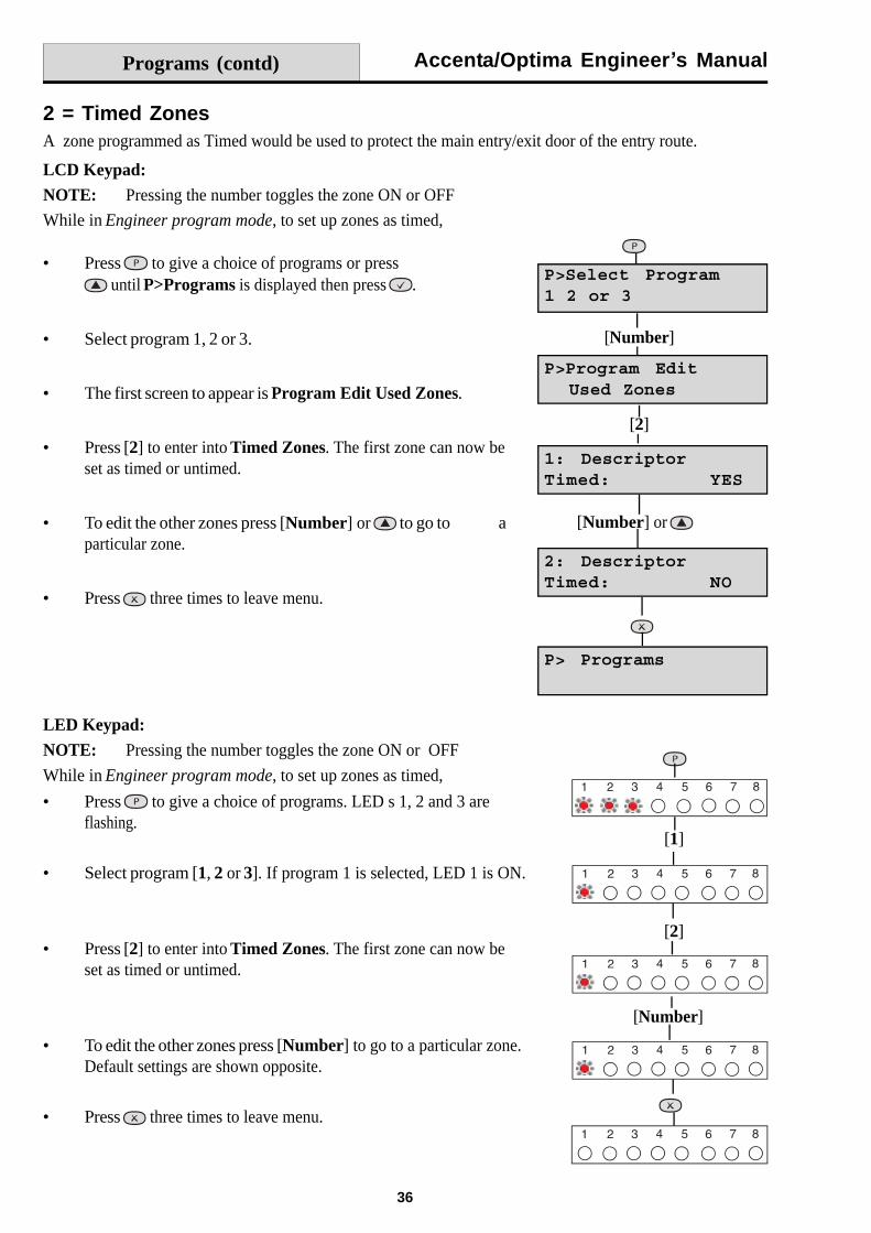
2 = Timed ZonesA zone programmed as Timed would be used to protect the main entry/exit door of the entry route.
LCD Keypad:NOTE: Pressing the number toggles the zone ON or OFF
While in Engineer program mode, to set up zones as timed,
Press to give a choice of programs or press until P>Programs is displayed then press .
Select program 1, 2 or 3.
The first screen to appear is Program Edit Used Zones.
Press [2] to enter into Timed Zones. The first zone can now beset as timed or untimed.
To edit the other zones press [Number] or
to go to aparticular zone.
Press three times to leave menu.
LED Keypad:NOTE: Pressing the number toggles the zone ON or OFF
While in Engineer program mode, to set up zones as timed,
Press to give a choice of programs. LED s 1, 2 and 3 areflashing.
Select program [1, 2 or 3]. If program 1 is selected, LED 1 is ON.
Press [2] to enter into Timed Zones. The first zone can now beset as timed or untimed.
To edit the other zones press [Number] to go to a particular zone.Default settings are shown opposite.
Press three times to leave menu.
Programs (contd)
[2]
[Number]
[Number] or
[1]
[2]
[Number]
Accenta/Optima Engineer s Manual
37
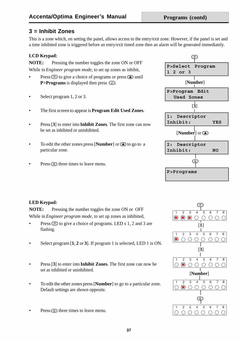
3 = Inhibit ZonesThis is a zone which, on setting the panel, allows access to the entry/exit zone. However, if the panel is set anda time inhibited zone is triggered before an entry/exit timed zone then an alarm will be generated immediately.
LCD Keypad:NOTE: Pressing the number toggles the zone ON or OFF
While in Engineer program mode, to set up zones as inhibit,
Press to give a choice of programs or press untilP>Programs is displayed then press .
Select program 1, 2 or 3.
The first screen to appear is Program Edit Used Zones.
Press [3] to enter into Inhibit Zones. The first zone can nowbe set as inhibited or uninhibited.
To edit the other zones press [Number] or
to go to aparticular zone.
Press three times to leave menu.
LED Keypad:NOTE: Pressing the number toggles the zone ON or OFF
While in Engineer program mode, to set up zones as inhibited,
Press to give a choice of programs. LED s 1, 2 and 3 areflashing.
Select program [1, 2 or 3]. If program 1 is selected, LED 1 is ON.
Press [3] to enter into Inhibit Zones. The first zone can now beset as inhibited or uninhibited.
To edit the other zones press [Number] to go to a particular zone.Default settings are shown opposite.
Press three times to leave menu.
Programs (contd)
[3]
[Number]
[Number] or
[1]
[3]
[Number]
Accenta/Optima Engineer s Manual
38
Programs (contd)
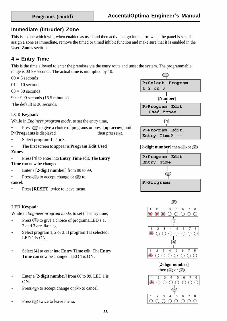
Immediate (Intruder) ZoneThis is a zone which will, when enabled as used and then activated, go into alarm when the panel is set. Toassign a zone as immediate, remove the timed or timed inhibit function and make sure that it is enabled in theUsed Zones section.
4 = Entry TimeThis is the time allowed to enter the premises via the entry route and unset the system. The programmablerange is 00-99 seconds. The actual time is multiplied by 10.
00 = 5 seconds
01 = 10 seconds
03 = 30 seconds
99 = 990 seconds (16.5 minutes)
The default is 30 seconds.
LCD Keypad:While in Engineer program mode, to set the entry time,
Press to give a choice of programs or press [up arrow] untilP>Programs is displayed then press .
Select program 1, 2 or 3.
The first screen to appear is Program Edit UsedZones.
Press [4] to enter into Entry Time edit. The EntryTime can now be changed.
Enter a [2-digit number] from 00 to 99.
Press to accept change or tocancel.
Press [RESET] twice to leave menu.
LED Keypad:While in Engineer program mode, to set the entry time,
Press to give a choice of programs.LED s 1,2 and 3 are flashing.
Select program 1, 2 or 3. If program 1 is selected,LED 1 is ON.
Select [4] to enter into Entry Time edit. The EntryTime can now be changed. LED 1 is ON.
Enter a [2-digit number] from 00 to 99. LED 1 isON.
Press to accept change or to cancel.
Press twice to leave menu.
[4]
[Number]
[2-digit number] then or
[1]
[4]
[2-digit number]then or
Accenta/Optima Engineer s Manual
39
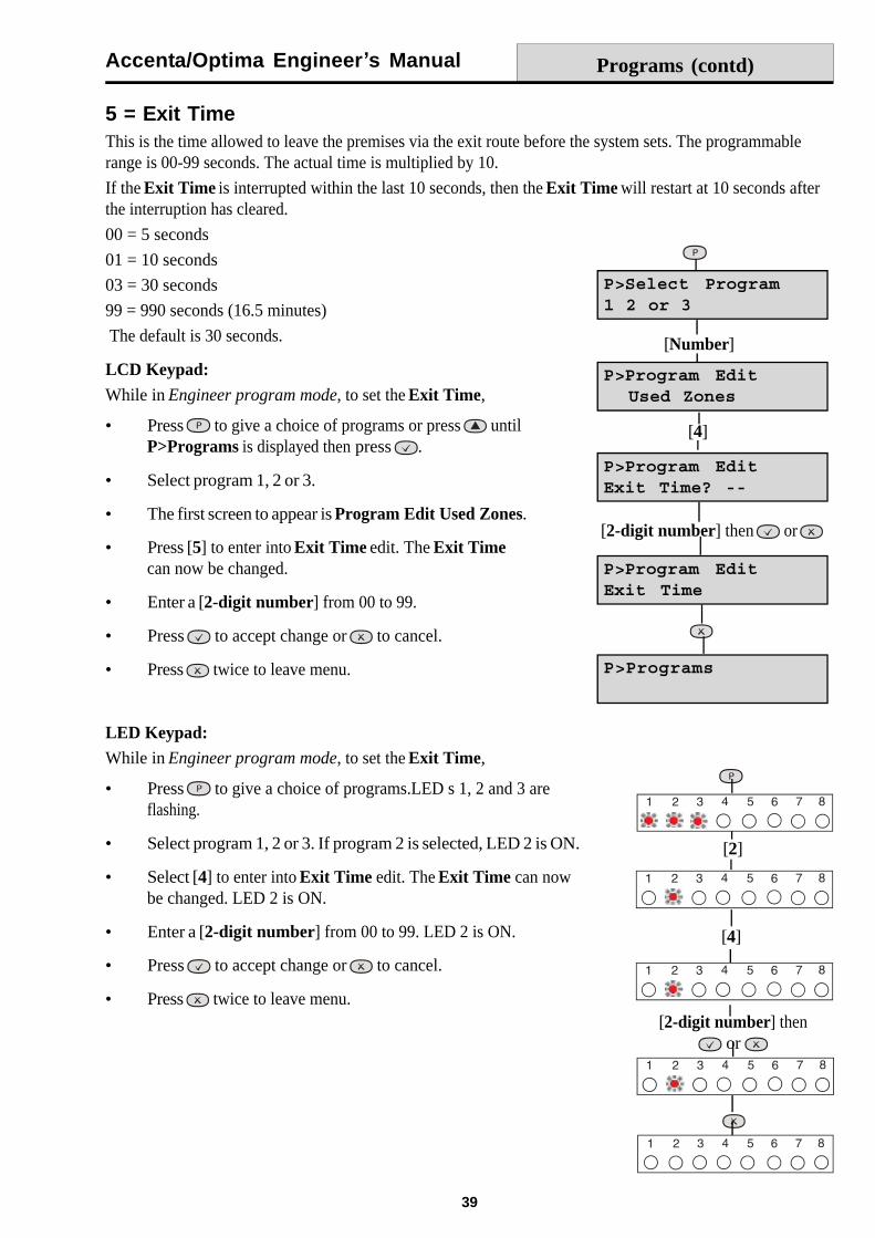
5 = Exit TimeThis is the time allowed to leave the premises via the exit route before the system sets. The programmablerange is 00-99 seconds. The actual time is multiplied by 10.
If the Exit Time is interrupted within the last 10 seconds, then the Exit Time will restart at 10 seconds afterthe interruption has cleared.
00 = 5 seconds
01 = 10 seconds
03 = 30 seconds
99 = 990 seconds (16.5 minutes)
The default is 30 seconds.
LCD Keypad:While in Engineer program mode, to set the Exit Time,
Press to give a choice of programs or press untilP>Programs is displayed then press .
Select program 1, 2 or 3.
The first screen to appear is Program Edit Used Zones.
Press [5] to enter into Exit Time edit. The Exit Timecan now be changed.
Enter a [2-digit number] from 00 to 99.
Press to accept change or to cancel.
Press twice to leave menu.
LED Keypad:While in Engineer program mode, to set the Exit Time,
Press to give a choice of programs.LED s 1, 2 and 3 areflashing.
Select program 1, 2 or 3. If program 2 is selected, LED 2 is ON.
Select [4] to enter into Exit Time edit. The Exit Time can nowbe changed. LED 2 is ON.
Enter a [2-digit number] from 00 to 99. LED 2 is ON.
Press to accept change or to cancel.
Press twice to leave menu.
Programs (contd)
[4]
[Number]
[2-digit number] then or
[2]
[4]
[2-digit number] then or

Accenta/Optima Engineer s Manual
40
6 = Exit ModeThis program determines the way the panel functions during the exit time. There are four settings:
0 = DisabledA disabled program is not available for use and cannot be selected at setting time. Program 1 cannot bedisabled.
1 = TimedA timed program will become Set as the Exit timer expires.
2 = Final DoorA final door program will be set five seconds after a timed zone is closed if the rest of the zones are clear toset.
NOTE: Final door programs must have a timed zone in order to operate correctly.
3 = Silent TimedThis operates exactly the same as Timed but completely silent without internal sounder signal.
NOTE: If a program is not selected when the user sets the system, program 1 will automatically set.Therefore program 1 is usually considered as the Full Set Program containing all the zones.
LCD Keypad:While in Engineer program mode, to set the Exit Mode ,
Press to give a choice of programs or press untilP>Programs is displayed then press .
Select program 1, 2 or 3.
The first screen to appear is Program Edit Used Zones.
Press [6] to enter into Exit Mode edit. The Exit Mode cannow be changed.
Enter [0, 1, 2 or 3] for required Exit Mode.
NOTE: Program Mode DISABLED is not available in program 1.
Press three times to save change and leave menu.
Programs (contd)
[6]
[Number]
[0, 1, 2 or 3]
Accenta/Optima Engineer s Manual
41
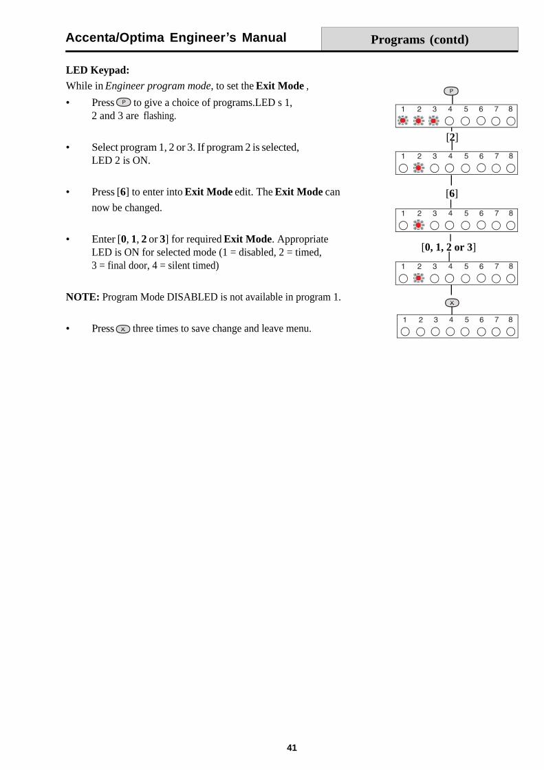
LED Keypad:While in Engineer program mode, to set the Exit Mode ,
Press to give a choice of programs.LED s 1,2 and 3 are flashing.
Select program 1, 2 or 3. If program 2 is selected,LED 2 is ON.
Press [6] to enter into Exit Mode edit. The Exit Mode can
now be changed.
Enter [0, 1, 2 or 3] for required Exit Mode. AppropriateLED is ON for selected mode (1 = disabled, 2 = timed,3 = final door, 4 = silent timed)
NOTE: Program Mode DISABLED is not available in program 1.
Press three times to save change and leave menu.
Programs (contd)
[2]
[6]
[0, 1, 2 or 3]
Accenta/Optima Engineer s Manual
42
Operating System
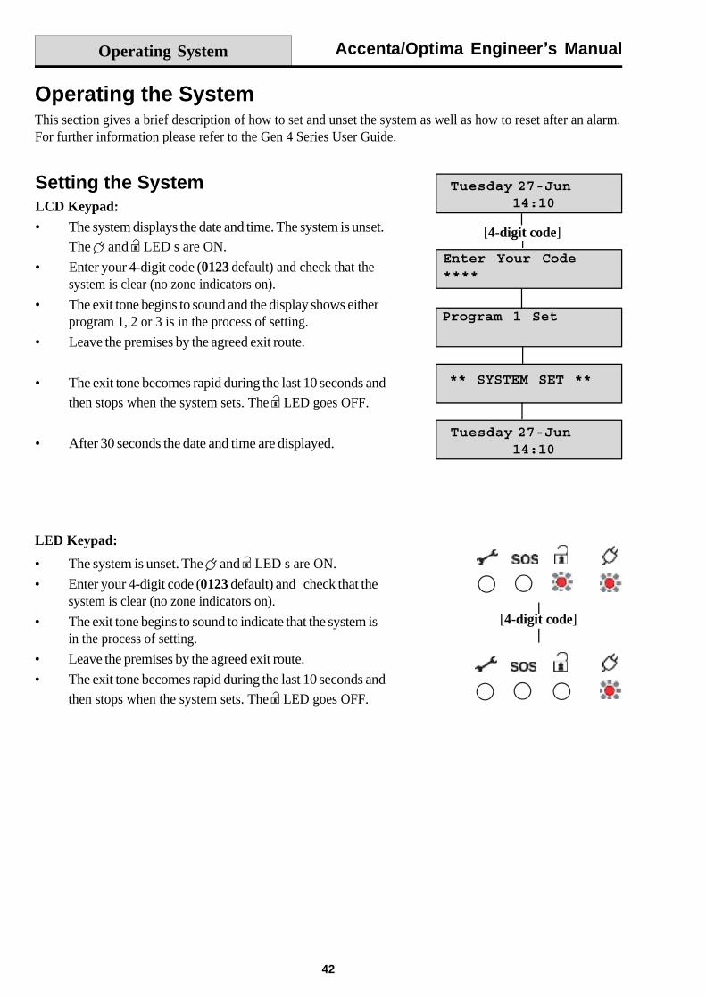
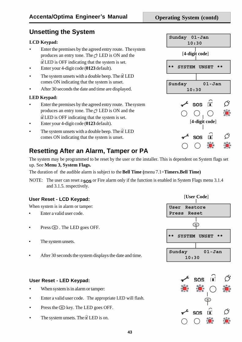
Operating the SystemThis section gives a brief description of how to set and unset the system as well as how to reset after an alarm.For further information please refer to the Gen 4 Series User Guide.
Setting the SystemLCD Keypad:
The system displays the date and time. The system is unset.The and LED s are ON.
Enter your 4-digit code (0123 default) and check that thesystem is clear (no zone indicators on).
The exit tone begins to sound and the display shows eitherprogram 1, 2 or 3 is in the process of setting.
Leave the premises by the agreed exit route.
The exit tone becomes rapid during the last 10 seconds andthen stops when the system sets. The LED goes OFF.
After 30 seconds the date and time are displayed.
LED Keypad:
The system is unset. The and LED s are ON.
Enter your 4-digit code (0123 default) and check that thesystem is clear (no zone indicators on).
The exit tone begins to sound to indicate that the system isin the process of setting.
Leave the premises by the agreed exit route.
The exit tone becomes rapid during the last 10 seconds andthen stops when the system sets. The LED goes OFF.
[4-digit code]
[4-digit code]
Accenta/Optima Engineer s Manual
43
LCD Keypad:Enter the premises by the agreed entry route. Thesystemproduces an entry tone. The LED is ON and the
LED is OFF indicating that the system is set.Enter your 4-digit code (0123 default).
The system unsets with a double beep. The LEDcomes ON indicating that the system is unset.
After 30 seconds the date and time are displayed.
Resetting After an Alarm, Tamper or PAThe system may be programmed to be reset by the user or the installer. This is dependent on System flags setup. See Menu 3, System Flags.The duration of the audible alarm is subject to the Bell Time (menu 7.1=Timers.Bell Time)
NOTE: The user can reset a or Fire alarm only if the function is enabled in System Flags menu 3.1.4and 3.1.5. respectively.
LED Keypad:Enter the premises by the agreed entry route. Thesystemproduces an entry tone. The LED is ON and the
LED is OFF indicating that the system is set.Enter your 4-digit code (0123 default).
The system unsets with a double beep. The LEDcomes ON indicating that the system is unset.
User Reset - LCD Keypad:When system is in alarm or tamper:
Enter a valid user code.
Press . The LED goes OFF.
The system unsets.
After 30 seconds the system displays the date and time.
User Reset - LED Keypad:
When system is in alarm or tamper:
Enter a valid user code. The appropriate LED will flash.
Press the key. The LED goes OFF.
The system unsets. The LED is on.
Operating System (contd)
Unsetting the System
[4-digit code]
[User Code]
[4-digit code]
Accenta/Optima Engineer s Manual
44
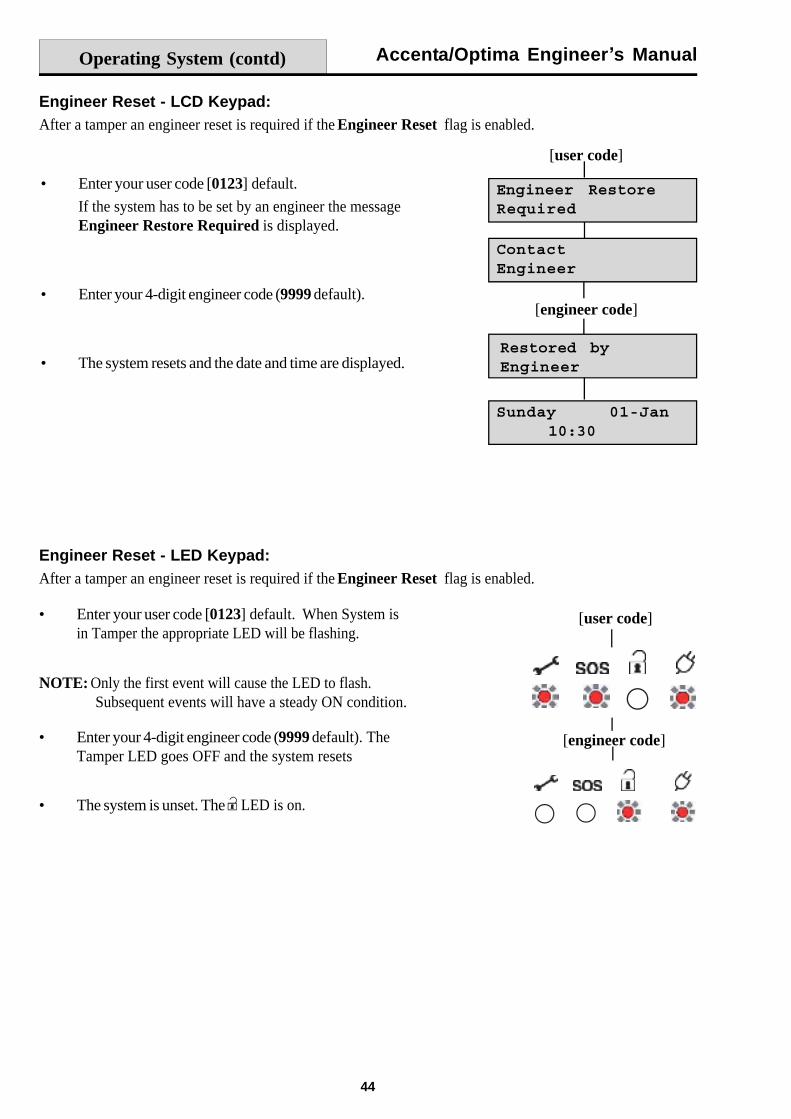
Engineer Reset - LCD Keypad:After a tamper an engineer reset is required if the Engineer Reset flag is enabled.
Enter your user code [0123] default. When System isin Tamper the appropriate LED will be flashing.
NOTE: Only the first event will cause the LED to flash.Subsequent events will have a steady ON condition.
Enter your 4-digit engineer code (9999 default). TheTamper LED goes OFF and the system resets
The system is unset. The LED is on.
Operating System (contd)
Enter your user code [0123] default.
If the system has to be set by an engineer the messageEngineer Restore Required is displayed.
Enter your 4-digit engineer code (9999 default).
The system resets and the date and time are displayed.
Engineer Reset - LED Keypad:After a tamper an engineer reset is required if the Engineer Reset flag is enabled.
[engineer code]
[user code]
[engineer code]
[user code]

Accenta/Optima Engineer s Manual
45
FaultsFault conditions are often the result of minor installation errors.
Whenever working close to the mains supply or connector, you should exercise extreme caution. Alwaysisolate the mains supply before removing the control panel covers.
CodesAs supplied the default user code is 0123 and the engineer code is 9999. Both codes can revert back todefault settings. See Defaulting Panel to Factory Settings and Defaulting User Code 1 and EngineerCode.
Engineer ModeWhen the system is unset, the Engineer Program is accessed directly, using the engineer code.
Tamper/SOS/Fire FaultsIf a tamper, SOS or Fire fault is present on the system, it will go to a lock out condition (showing theappropriate indication). The keypad will produce audible responses and the system will allow an engineer toaccess the panel and rectify the fault. The panel will remain in lockout until the fault has been rectified.
Zone WiringIt is recommended that only one detector is wired to each zone as this allows the event log to record theoperation of each detector. However, if multiple detectors are connected to a zone, their alarm outputs mustbe wired in series.
If used, all detector tamper outputs are wired in series back to the control panel to the terminal markedTAMP. (see Figure 7. Security Zone Wiring).
Zone Faults Where a permanent zone fault is showing and the loop resistance is found to be in order, the mostprobable cause is a short circuit between the zone wiring and the tamper wiring. When measured with amultimeter the series resistance between the zone and tamper wiring should be infinitely high.
If after thorough investigation a fault condition persists the panel can be set to factory defaults (see DefaultingPanel to Factory Settings).
Fuses Before testing or replacing any fuses, ALL power must be removed. Fuses which fail continually arealmost certainly the result of a short circuit or low resistance across the 13V supply or external siren(bell box) supply (terminal D).
Faults
Accenta/Optima Engineer s Manual
46
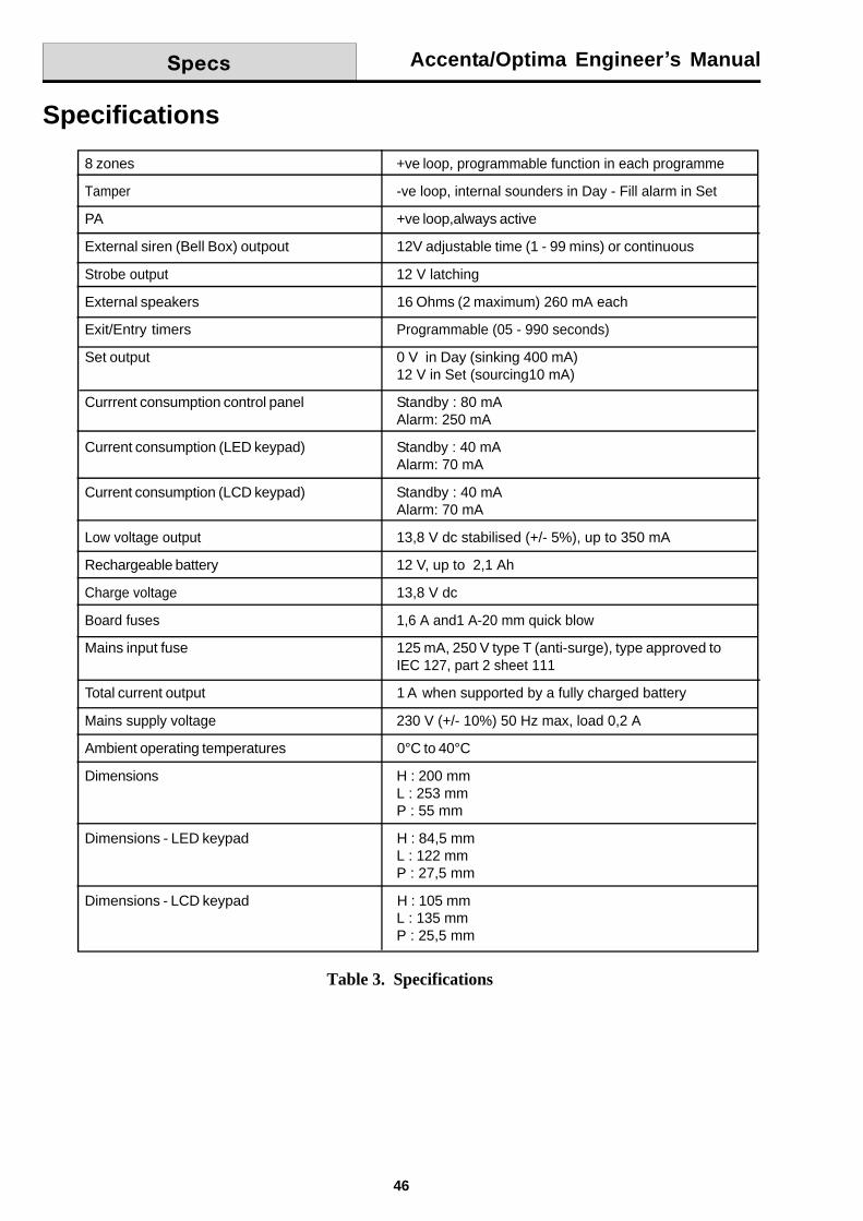
Specifications
Table 3. Specifications
8 zones +ve loop, programmable function in each programme
Tamper -ve loop, internal sounders in Day - Fill alarm in Set
PA +ve loop,always active
External siren (Bell Box) outpout 12V adjustable time (1 - 99 mins) or continuous
Strobe output 12 V latching
External speakers 16 Ohms (2 maximum) 260 mA each
Exit/Entry timers Programmable (05 - 990 seconds)
Set output 0 V in Day (sinking 400 mA)12 V in Set (sourcing10 mA)
Currrent consumption control panel Standby : 80 mAAlarm: 250 mA
Current consumption (LED keypad) Standby : 40 mAAlarm: 70 mA
Current consumption (LCD keypad) Standby : 40 mAAlarm: 70 mA
Low voltage output 13,8 V dc stabilised (+/- 5%), up to 350 mA
Rechargeable battery 12 V, up to 2,1 Ah
Charge voltage 13,8 V dc
Board fuses 1,6 A and1 A-20 mm quick blow
Mains input fuse 125 mA, 250 V type T (anti-surge), type approved toIEC 127, part 2 sheet 111
Total current output 1 A when supported by a fully charged battery
Mains supply voltage 230 V (+/- 10%) 50 Hz max, load 0,2 A
Ambient operating temperatures 0°C to 40°C
Dimensions H : 200 mmL : 253 mmP : 55 mm
Dimensions - LED keypad H : 84,5 mmL : 122 mmP : 27,5 mm
Dimensions - LCD keypad H : 105 mmL : 135 mmP : 25,5 mm
Accenta/Optima Engineer s Manual
47
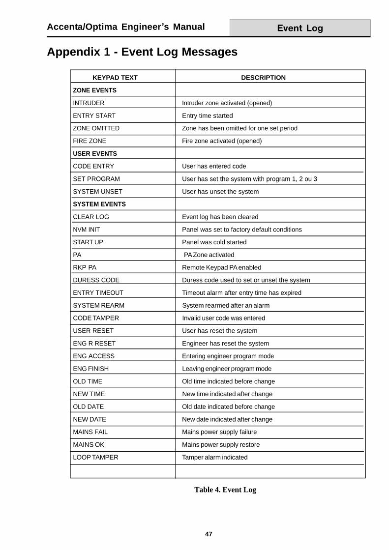
Appendix 1 - Event Log Messages
Table 4. Event Log
KEYPAD TEXT DESCRIPTION
ZONE EVENTS
INTRUDER Intruder zone activated (opened)
ENTRY START Entry time started
ZONE OMITTED Zone has been omitted for one set period
FIRE ZONE Fire zone activated (opened)
USER EVENTS
CODE ENTRY User has entered code
SET PROGRAM User has set the system with program 1, 2 ou 3
SYSTEM UNSET User has unset the system
SYSTEM EVENTS
CLEAR LOG Event log has been cleared
NVM INIT Panel was set to factory default conditions
START UP Panel was cold started
PA PA Zone activated
RKP PA Remote Keypad PA enabled
DURESS CODE Duress code used to set or unset the system
ENTRY TIMEOUT Timeout alarm after entry time has expired
SYSTEM REARM System rearmed after an alarm
CODE TAMPER Invalid user code was entered
USER RESET User has reset the system
ENG R RESET Engineer has reset the system
ENG ACCESS Entering engineer program mode
ENG FINISH Leaving engineer program mode
OLD TIME Old time indicated before change
NEW TIME New time indicated after change
OLD DATE Old date indicated before change
NEW DATE New date indicated after change
MAINS FAIL Mains power supply failure
MAINS OK Mains power supply restore
LOOP TAMPER Tamper alarm indicated

Accenta/Optima Engineer s Manual
48

Accenta/Optima Engineer s Manual
49
Appendix 2 - Library
Attic
Back Door
Basement
Bathroom
Bedroom 1
Bedroom 2
Bedroom 3
Conservatory
Dining Room
Fire Zone
Front Door
Garage
Hall
Kitchen
Landing
Living Room
Lounge
Patio
Porch
Stairs
Study
Utility Room
Window 1
Window 2
Window 3

Accenta/Optima Engineer s Manual
50

Accenta/Optima Engineer s Manual
51
Servicing Organisation Details
Servicing Organisation name:
Telephone number:
Date of Installation:
Account Number:
Parts8SP399A Accenta mini panel with LCD keypad
8EP396A Optima compact panel
8EP417A Accenta LCD remote keypad
8EP416 Accenta LED remote keypad
8EP276A Informa
8EP289 Extension speaker
IS215T 12 meter PIR
Servicing/Parts
Resistance( ) Area protection and equipment used (eg PIR, Contacts)
Zone 1
Zone 2
Zone 3
Zone 4
Zone 5
Zone 6
Zone 7
Zone 8
Table 5. Zones and Resistance
Accenta/Optima Engineer s Manual
52
Honeywell Security (UK 64)Newhouse Industrial EstateMotherwellLanarkshireML1 5SBUK
© Copyright Honeywell SecurityEKZ014400A