Embed Size (px)
DESCRIPTION
Accelerator Assembly & Installation Planning. Gregory Fries Project Engineer, Accelerator Systems Division ASAC Review of NSLS-II October 14-15, 2010. Outline. Storage Ring Magnet/Girder Integration Phasing of Installation Coordination with Conventional Facilities - PowerPoint PPT Presentation
Citation preview

1 BROOKHAVEN SCIENCE ASSOCIATES
Accelerator Assembly & Installation Planning
Gregory FriesProject Engineer, Accelerator Systems Division
ASAC Review of NSLS-IIOctober 14-15, 2010

2 BROOKHAVEN SCIENCE ASSOCIATES
Outline
• Storage Ring Magnet/Girder Integration• Phasing of Installation• Coordination with Conventional Facilities• Storage Ring Installation• Injector Installation• Storage and Rigging• Experimental Installation• Magnetic Measurement Lab• Labor Profile• Challenges• Summary

3 BROOKHAVEN SCIENCE ASSOCIATES
Key Aspects of Production and Installation
Accelerator Production –• We procure injector sub-systems (Linac, Booster Ring) • We build (integrate) Transfer Lines, B-RF and SR components
Accelerator Installation –• Storage Ring BNL• Storage Ring RF BNL w/ vendor installing transmitter• Booster RF BNL• Transport Lines BNL• Linac Vendor w/ BNL oversight• Booster Ring Vendor using BNL technicians for all
hands–on work w/ BNL oversight
4 BROOKHAVEN SCIENCE ASSOCIATES
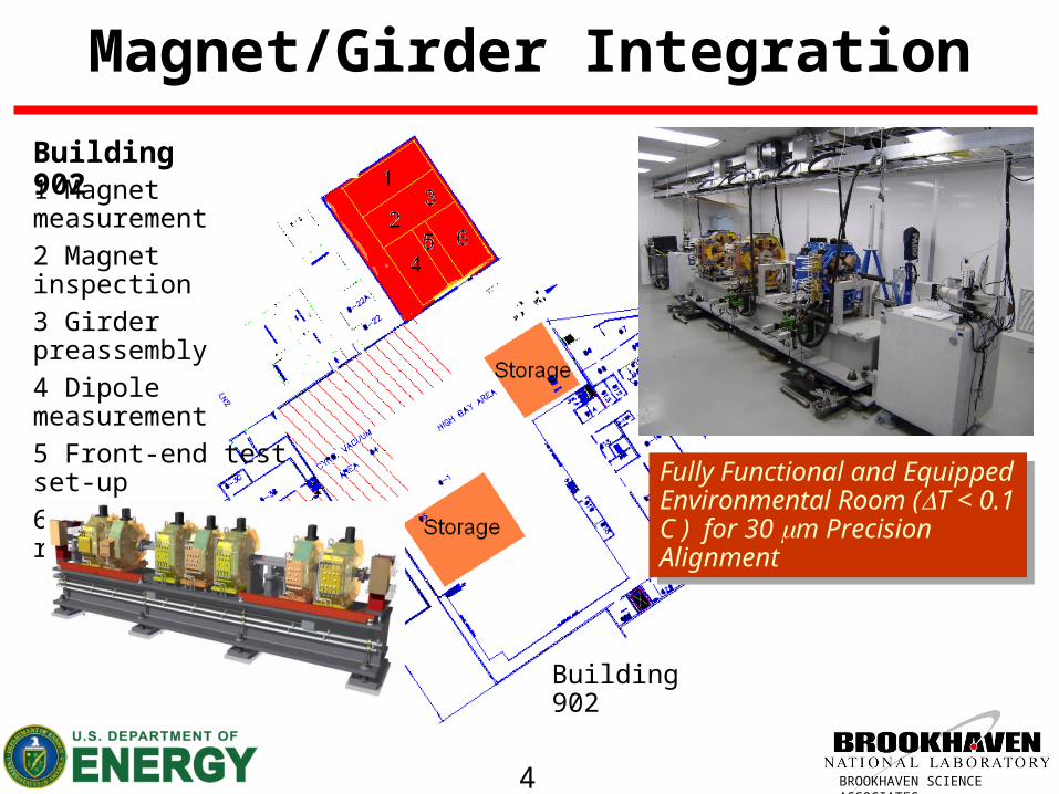
Magnet/Girder Integration
1 Magnet measurement2 Magnet inspection3 Girder preassembly4 Dipole measurement5 Front-end test set-up6 Environmental room
Building 902
Building 902
Fully Functional and Equipped Environmental Room (T < 0.1 C ) for 30 m Precision Alignment
Fully Functional and Equipped Environmental Room (T < 0.1 C ) for 30 m Precision Alignment

5 BROOKHAVEN SCIENCE ASSOCIATES
Magnet/Girder Integration WorkflowIn Cleanroom
• 90 MP girders• 60 dipole girders

6 BROOKHAVEN SCIENCE ASSOCIATES
Magnet/Girder Precision Alignment Workflow
2 girders /months 2 girders / week
@ 18 months (incl. learning curve effect)
Starting March, 2011 Finish Oct, 2012
• Will be learning curve• In beginning, 2nd
survey will occur
• Workflow flexible based on component availability
• Prec. Alignment without all magnets
• Final magnets installed in tunnel
• Pre-assemble and store partially completed girders

7 BROOKHAVEN SCIENCE ASSOCIATES
Phasing of Construction and InstallationBeneficial Occupancy
Area DatePentant 1, Cooling Tower, Vehicle & Utility Tunnels
1-Feb-11
RF Building 23-Mar-11Injector Building 18-May-11Pentant 2 2-Jun-11Pentant 3 27-Sep-11Pentant 4 28-Nov-11Pentant 5 9-Feb-12

8 BROOKHAVEN SCIENCE ASSOCIATES
Installation and Operation Zones
Key Points:
• Utilities and infrastructure are segmented as shown by pentant
• Temp walls constructed separating BOD segments
• Installation and testing within these segments
• Linac/Booster test/commission may overlap with construction activities
1
2
B
L
34
5
RFRF

9 BROOKHAVEN SCIENCE ASSOCIATES
Coordination with Conventional Facilities
• Lay-down area for storage containers outside of building• Beneficial occupancy conditions for installation• Systematic hand-off of completed building zones
• BNL BORE process to be used for occupancy permits• Access to space with beneficial occupancy for installation
while construction continues• Interaction of installation activity with LOB construction to
avoid potential interference• CFD represented in ASD installation meetings• ASD reviewing all CFD ECNs for impact

10 BROOKHAVEN SCIENCE ASSOCIATES
Storage Ring Systems Installation
Per Pentant• Mechanical Utilities • Electrical Utilities• Magnet/Girder Assemblies• Vacuum System• Power Supplies• Beam Instrumentation• ControlsWhere Applicable• RF Systems• Beam Line FEs, DWs, IDs• Injection Straight
11 BROOKHAVEN SCIENCE ASSOCIATES
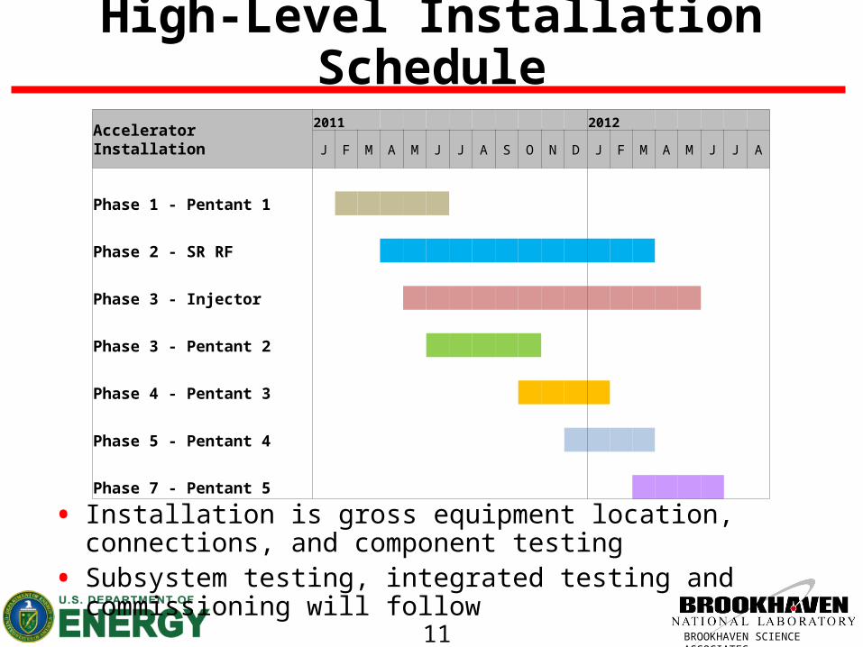
High-Level Installation Schedule
Accelerator Installation2011 2012
J F M A M J J A S O N D J F M A M J J A
Phase 1 - Pentant 1
Phase 2 - SR RF
Phase 3 - Injector
Phase 3 - Pentant 2
Phase 4 - Pentant 3
Phase 5 - Pentant 4
Phase 7 - Pentant 5
• Installation is gross equipment location, connections, and component testing• Subsystem testing, integrated testing and commissioning will follow

12 BROOKHAVEN SCIENCE ASSOCIATES
Storage Ring Pentant 1 Installation: Week
24 25 27 2823
Exp’l floor
Tunnel
Service Building
24 25 26 2722
Mezzanine
23
Status:~ 1/3 of material in buildingInstallation starting
26
Activities:•Prepare tunnel•Stage components on floor•Start cable tray on mezzanine
2

13 BROOKHAVEN SCIENCE ASSOCIATES
Storage Ring Pentant 1 Installation: Week 6
24 25 27 2823
Exp’l floor
Tunnel
Service Building
24 25 26 2722
Mezzanine
23
Status:Most material in buildingInstallation on mezzanineInstallation in tunnel
26
Activities:•Tray and manifolds in place in tunnel•Racks well underway•Stage cable and start pulling

14 BROOKHAVEN SCIENCE ASSOCIATES
Storage Ring Pentant 1 Installation: Week 12
24 25 27 2823
Exp’l floor
Tunnel
Service Building
24 25 26 2722
Mezzanine
23
Status:Most wiring pulledProcess utilities connected
26
Activities:•Girder installation•Populating racks•Terminating cables

15 BROOKHAVEN SCIENCE ASSOCIATES
Storage Ring Pentant 1 Installation: Week 20
24 25 27 2823
Exp’l floor
Tunnel
Service Building
24 25 26 2722
Mezzanine
23
Status:All equipment in placeSystem testing underway
26
Activities:• Final utility connections• Equipment shakeout

16 BROOKHAVEN SCIENCE ASSOCIATES
SR RF Installation
• BOD date for RF building – Mar 23, 2011• All systems delivered directly to RF building• RF Transmitter w/ klystron installed by vendor• Remaining RF systems installed by BNL
SR RF Installation2011 2012 2013
J F M A M J J A S O N D J F M A M J J A S O N D J F M A
Mech & Elect Utilities
Cabling, Wiring, Piping
RF Transmitter
Liquid Nitrogen System
Valve Box & Piping
Refrigeration System
RF Cavity

17 BROOKHAVEN SCIENCE ASSOCIATES
Injector Installation Phases
• Mechanical & Electrical Utilities• Booster RF• LtB Transport Line Part 1
• Through wall, up to vac valve in booster vault, needed to commission linac
• Linac• Booster• LtB Transport Line Part 2
• TL complete, need to commission booster• BtS Transport line Part 1
• Up to beam dump, needed to commission booster

18 BROOKHAVEN SCIENCE ASSOCIATES
Injector Installation Phases Layout
BtS TL Part 1
Booster
LtB TL Part 2Linac
LtB TL Part 1Phase Separation
Booster RF
Phase Separation (end of injector install)

19 BROOKHAVEN SCIENCE ASSOCIATES
Transport Line Magnet/Girder Integration
• Preassembly in injector service building
• Magnets, Girders, Vacuum, Diagnostics
• Pre-alignment• Pre-test

20 BROOKHAVEN SCIENCE ASSOCIATES
Injector Installation Schedule
Injector Installation2011 2012
J F M A M J J A S O N D J F M A M J J
Utilities - Mech & Elec
Phase 1 - Booster RF
Phase 2 - LtB TL Part 1
Phase 3 - Linac
Phase 4 - Booster
Phase 5 - LtB TL Part 2
Phase 6 - BtS Part 1
• Booster RF split into two phases: BR RF cavity & BR RF transmitter• BtS Part 2 is considered part of SR installation

21 BROOKHAVEN SCIENCE ASSOCIATES
Component Storage & Staging
• Reviewing storage requirements for each ASD group• Finalizing number of sea containers needed at site for storage
• Approx. 10-15 - 8 ft x 8 ft x 40 ft containers• Experimental floor will be used for staging
• Temporary cages may be installed

22 BROOKHAVEN SCIENCE ASSOCIATES
Lay-down Areas for Sea ContainersLay-down Area for SR Component Storage Containers
Lay-down Area for Linac & Booster Containers
Outside Access to Experimental Floor for Unloading(column 102)

23 BROOKHAVEN SCIENCE ASSOCIATES
Rigging Requirements
Item Qty. UOM DateHours (team)
TotalHours(team)
Weight(lbs)
Total Weight(lbs)
Dimensions From To Comments
RF Group
SR Transmitter 1 EA Jun-11 8 8 5,000 5,0006 x 2 x 2.3m
tentativeTruck RF Building
SR Transmitter 1 EA TBD 8 8 5,000 5,0006 x 2 x 2.3m
tentativeTruck RF Building
SR Transmitter Transformer 1 EA Jun-11 2 2 5,500 5,500 Truck RF Building Installed separately
SR Transmitter Transformer 1 EA TBD 2 2 5,500 5,500 Truck RF Building Installed separately
SR Klystron 1 EA Jun-11 4 4 2,750 2,750 Truck RF Building Horizontal-to-Vertical
SR Klystron 1 EA TBD 4 4 2,750 2,750 Truck RF Building Horizontal-to-Vertical
SR Cavity 1 EA Aug-12 16 16 10,000 10,000 TruckRF Straight in
TunnelInstalled in 20cm trench
SR Cavity 1 EA Nov-12 2 2 10,000 10,000 Truck 832 Installed in 20cm trench
Cold Box 1 EA Nov-11 8 8 5,600 5,600 TruckRF Building - Cryo
Mezzanine
Requires special forklift to 20', unit for rent identified by Bob Sikora
Dewar 1 EA Nov-11 4 4 3,800 3,800 `RF Building - Cryo
Mezzanine
Valve Box 2 EA Nov-11 6 12 3,300 6,600 TruckTunnel Mezzanine at
RFVerify difficulty to get on mezzanine
Booster Transmitter 1 EA Dec-11 8 8 5,000 5,000 Truck Injector RF Building
Booster Cavity 1 EA Dec-11 4 4 2,200 2,200 832 Booster TunnelAs soon as tunnel is available; preceeds transmitter

24 BROOKHAVEN SCIENCE ASSOCIATES
Rigging Summary & Status
• Reviewed requirements with the riggers• Will have two dedicated 3-man rigging teams• ASD installation coordinator will be contact to riggers• Rigging requirements will continue to be detailed

25 BROOKHAVEN SCIENCE ASSOCIATES
Component Transport
• Forklift has been ordered• 10,000 lbs. capacity• 208” max lift to reach mezzanine from
experimental floor
• Dolly system will be used for magnet/girder assembly transport

26 BROOKHAVEN SCIENCE ASSOCIATES
Installation Schedule
• Installation schedule currently being reviewed with each CAM and expanded for completeness, durations and logic
• Emphasis will be placed on installation schedule flexibility based on building and component availability

27 BROOKHAVEN SCIENCE ASSOCIATES
Experimental Installation
XFD Installation follows ASD installation by pentant
Activities Per Beamline• Pentant Hand-off from ASD• Pentant Clean-up• Hutches• Utilities• Beamline Components

28 BROOKHAVEN SCIENCE ASSOCIATES
Magnetic Measurement Lab
• 46’ x 25’ environmental room for ID measurement
• Located in building 832• 95% Complete• BORE scheduled for Oct. 18,
2010• Measurement equipment to
start arriving in Nov. 2010• No safety incidents during
construction

29 BROOKHAVEN SCIENCE ASSOCIATES
Installation Labor Profiles
• Installation ramps up midway through FY 11
• Peak effort is 108 FTE• ASD significant effort by term
technicians and contract labor• XFD extensive use of
installation labor provided by suppliers
• Note that this is project labor only; does not include additional beamlines or beamline transfer
0
20
40
60
80
100
120
FY11 FY12 FY13 FY14
Experimental
Accelerator
0
20
40
60
80
100
120
FY11 FY12 FY13 FY14
Assigned labor
Technician
Engineer
Scientist / Mgr

30 BROOKHAVEN SCIENCE ASSOCIATES
Challenges
• Coordinating multiple activities/teams/access during installation• Maintaining component delivery schedules• Adapting to delivery delays• Will epoxy floor installation on experimental floor impact ASD
installation schedule?• XFD installation needs might conflict with required flexibility of ASD
installation schedule (hand-over delays)

31 BROOKHAVEN SCIENCE ASSOCIATES
Summary
• Magnet/Girder integration plan well defined• Installation schedule in process of being expanded and re-
evaluated• Focus on flexibility in installation schedule based on availability of
building and components• Building to be available for start of ASD installation Feb ‘11• Detailing installation logistics • Rigging and storage requirements in process• Good communication established with CFD & XFD• Required labor profile in place• Conclusion: Installation Planning is very advanced

32 BROOKHAVEN SCIENCE ASSOCIATES
Acknowledgements
A. Broadbent, L. Doom, O. Dyling, R. Fliller, G. Ganetis, E. Golnar, D. Hatton, H. Hseuh, E. Johnson, J. O’Malley, J. Rose, T.
Shaftan, S. Sharma, O. Singh, J. Skaritka, T. Tanabe, F. Willeke