Embed Size (px)
Citation preview
National Energy Technology Laboratory
David C. Miller and James C. Fisher II
National Energy Technology Laboratory
July 2013
Accelerating Technology Development: Post Combustion Capture Sorbents
2 2
• Carbon Capture Challenge
• Computational Tools to Accelerate Technology Development
• Experimental Carbon Capture Research @ NETL
• Multiscale Model Development, Simulation & Optimization
• Experimental Validation
• Conclusions
Outline
3
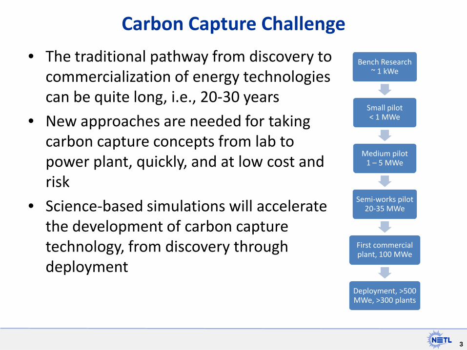
Carbon Capture Challenge
• The traditional pathway from discovery to commercialization of energy technologies can be quite long, i.e., 20-30 years
• New approaches are needed for taking carbon capture concepts from lab to power plant, quickly, and at low cost and risk
• Science-based simulations will accelerate the development of carbon capture technology, from discovery through deployment
Bench Research ~ 1 kWe
Small pilot < 1 MWe
Medium pilot 1 – 5 MWe
Semi-works pilot 20-35 MWe
First commercial plant, 100 MWe
Deployment, >500 MWe, >300 plants

4 4
For Accelerating Technology Development
National Labs Academia Industry
Identify promising concepts
Reduce the time for design &
troubleshooting
Quantify the technical risk, to enable reaching
larger scales, earlier
Stabilize the cost during commercial
deployment
5 5
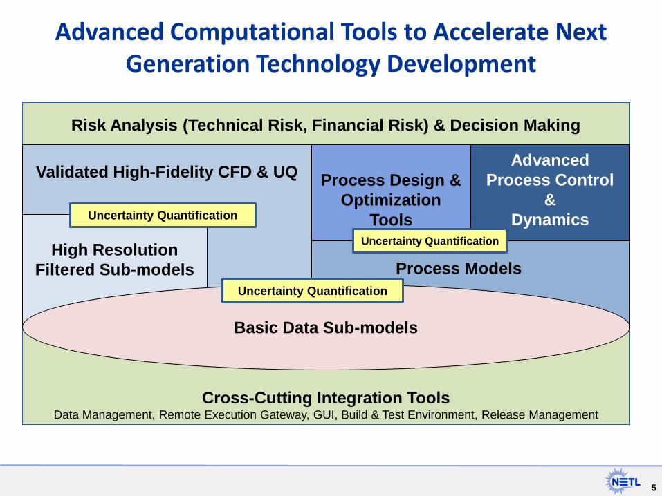
Risk Analysis (Technical Risk, Financial Risk) & Decision Making
Process Design &
Optimization Tools
Cross-Cutting Integration Tools Data Management, Remote Execution Gateway, GUI, Build & Test Environment, Release Management
Process Models
Validated High-Fidelity CFD & UQ
High Resolution
Filtered Sub-models
Advanced Computational Tools to Accelerate Next Generation Technology Development
Basic Data Sub-models
Advanced Process Control
& Dynamics
Uncertainty Quantification
Uncertainty Quantification
Uncertainty Quantification
6 6
Simulation & Experiments to reduce time for design/troubleshooting
Heat-transfer-tube-scale hydrodynamics
Expe
rimen
tal V
alid
atio
n
Process Models & Optimized Process
Experimental Kinetic/Mass Transfer Data
7 7
• Carbon Capture Challenge
• Computational Tools to Accelerate Technology Development
• Experimental Carbon Capture Research @ NETL
• Multiscale Model Development, Simulation & Optimization
• Experimental Validation
• Conclusions
Outline
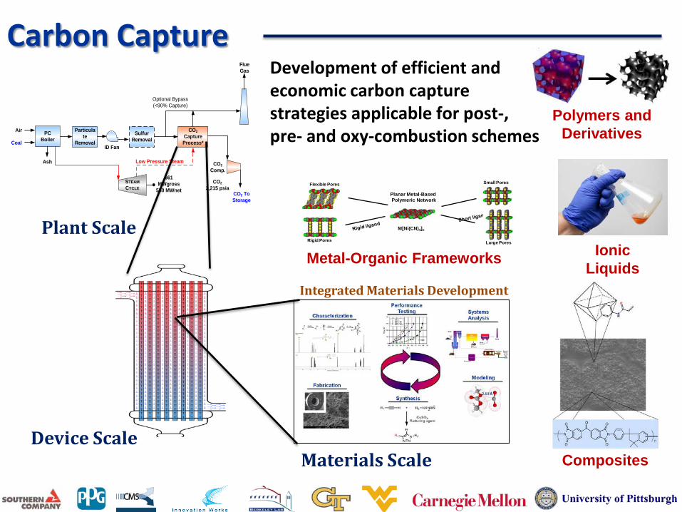
Carbon Capture
PC Boiler
Sulfur Removal
Particulate
Removal
Ash
Coal
STEAMCYCLE
CO2 CaptureProcess*
ID Fan
Air
CO22,215 psia
661 MWgross
550 MWnet
CO2Comp.
Flue Gas
CO2 To Storage
Low Pressure Steam
Optional Bypass(<90% Capture)
Plant Scale
Device Scale
Integrated Materials Development
Ionic Liquids
Composites
Small Pores
Large Pores
Flexible Pores
Rigid Pores
Planar Metal-Based Polymeric Network
M[Ni(CN)4]n
Metal-Organic Frameworks
Polymers and Derivatives
Materials Scale
Development of efficient and economic carbon capture strategies applicable for post-, pre- and oxy-combustion schemes
9
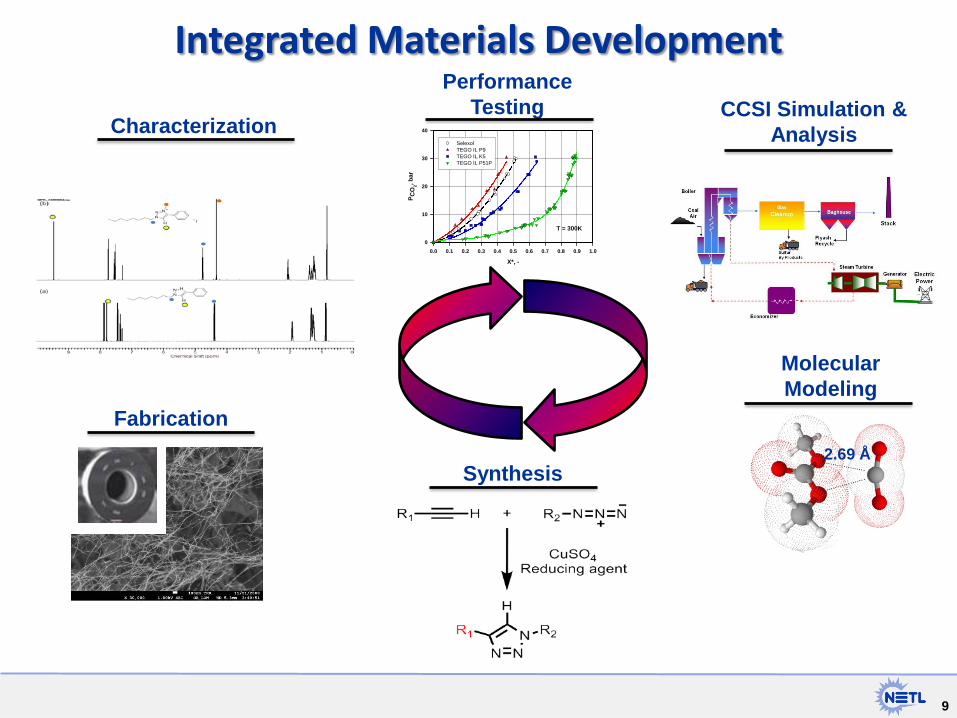
Integrated Materials Development
Synthesis
Molecular Modeling
Characterization
Performance Testing CCSI Simulation &
Analysis
X*, -
0.0 0.1 0.2 0.3 0.4 0.5 0.6 0.7 0.8 0.9 1.0
P CO
2, bar
0
10
20
30
40
SelexolTEGO IL P9TEGO IL K5TEGO IL P51P
T = 300K
2.69 Å
Fabrication
10
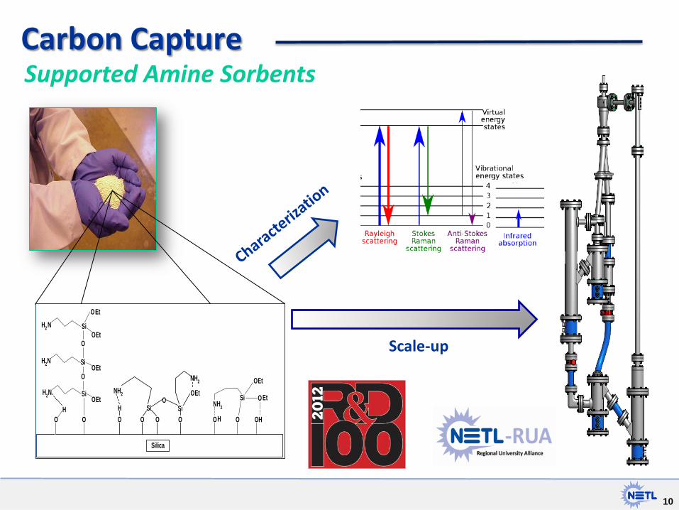
Supported Amine Sorbents
Et
NH2
NH2
OH
OOOSi
OSi
O
O
H2
H2
H2
OH
N Si
O
N Si
SiN
O
O
OEt
Et
Et
Et
O
O
O O OHH
Si O
O
NH2
Et
Et
Silica
Scale-up
Carbon Capture
11
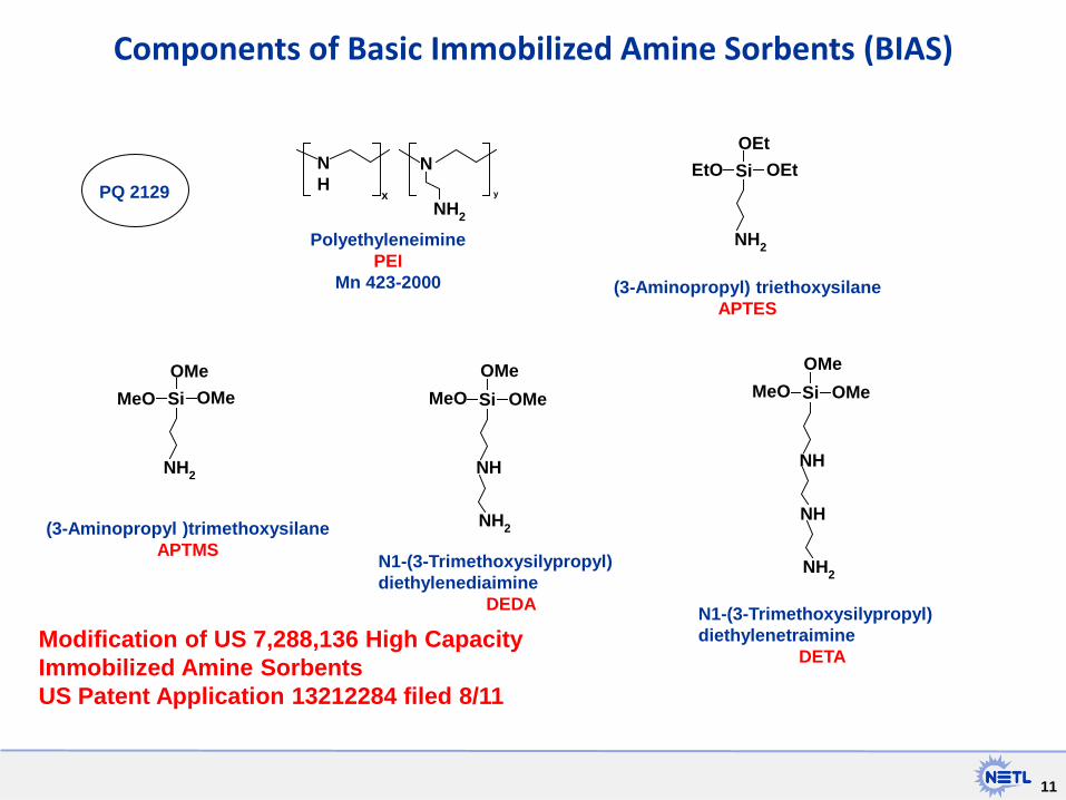
Components of Basic Immobilized Amine Sorbents (BIAS)
OEtSiOEt
EtO
NH2
Si OMeOMe
MeO
NH2
Si
NH
NH2
OMeOMeMeO Si
NH
OMeOMeMeO
NH2
NH
NH
N
NH2
x y
N1-(3-Trimethoxysilypropyl) diethylenetraimine
DETA
N1-(3-Trimethoxysilypropyl) diethylenediaimine
DEDA
(3-Aminopropyl )trimethoxysilane APTMS
(3-Aminopropyl) triethoxysilane APTES
Polyethyleneimine PEI
Mn 423-2000
Modification of US 7,288,136 High Capacity Immobilized Amine Sorbents US Patent Application 13212284 filed 8/11
PQ 2129

12
Sorbent AX Two BIAS sorbents are being tested: AX and 32D Sorbent AX
• 40% PEI - BASF Mn 2000
• Mesoporous Silica support- PQ Inc 2129
• 8 - 15 gal. drums from ADA
• Capacity (avg.) = 2.82 mmole CO2/g adsorbent ranging from 2.60-2.87 for n=7
• ADA packed bed, 13-14% CO2, ~55oC Capacity ( avg.) =1.25 avg. mmole CO2/g adsorbent
• umf=0.48 cm/s
• Particles behavior is Geldart Group A
Sauter mean particle diameter (μm) 114
Spericity (UNITLESS) 0.86
Particle porosity (UNITLESS) 0.39
Particle skeletal density (g/cc) 1.50
Particle density (g/cc) 0.91 0
0.2
0.4
0.6
0.8
1
1.2
0.000 0.002 0.004 0.006 0.008 0.010 0.012
ΔP·
A/g·
m (F
ract
ion)
Velocity (m/s)

13
BIAS Sorbent Testing
0
0.5
1
1.5
2
2.5
3
0 100 200 300
CO2
Capa
city
(mol
/kg)
Cycle Number
250 cycle stability under humidified conditions Regeneration at 105 oC with 90% steam
0
25
50
75
100
11:00 12:00 13:00 14:00 15:00 16:00
H2O
(%)
Time
H2O …
Sorbent ∆ CO2 Capacity/ Cum SO2 (mol/mol)
∆ CO2 Capacity/ Cum NO2 (mol/mol)
PEI / PMMA 0.91 0.68
PEI / Cariact 1.04 0.96
0 10 20 30 40 50 60 70 80 90
100
0 1 2 3 4 5 6 7 8 9 10 11 12 Run Number
CO2 SO2
Accelerated SOX testing
14 14
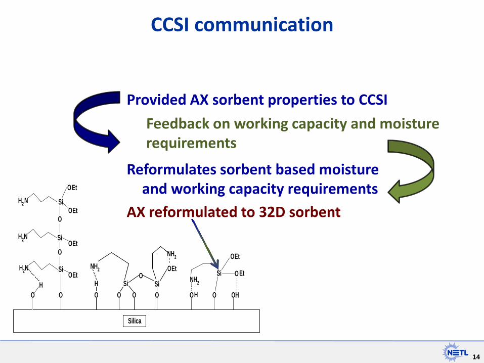
CCSI communication
Feedback on working capacity and moisture requirements
Et
NH2
NH2
OH
OOOSi
OSi
O
O
H2
H2
H2
OH
N Si
O
N Si
SiN
O
O
OEt
Et
Et
Et
O
O
O O OHH
Si O
O
NH2
Et
Et
Silica
Provided AX sorbent properties to CCSI
Reformulates sorbent based moisture and working capacity requirements
AX reformulated to 32D sorbent

15
Polyethyleneimine Silane Coupling
NH
N
NH2
x y
Polyethyleneimine Mn 423-2000
Simple Scalable Acceptable Capacity Moisture Resistance Stability Saleable
Pressure Chemical – Pan Dyer
Aminosilanes
NH
N
NH2
x y
Si
NH2
OEt
OEt
O Si
NH2
OEt
OEt
Synthesis was scaled to 1,000 lb range
16
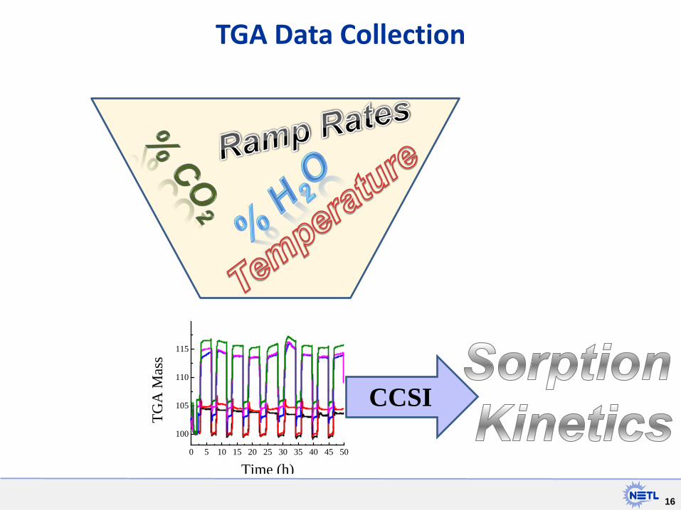
TGA Data Collection
0 5 10 15 20 25 30 35 40 45 50
100
105
110
115
TGA
Mas
s
Time (h)
CCSI
17
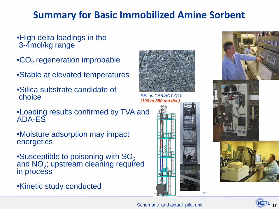
Summary for Basic Immobilized Amine Sorbent
PEI on CARiACT Q10 (100 to 350 µm dia.)
Schematic and actual pilot unit
•High delta loadings in the 3-4mol/kg range
•CO2 regeneration improbable
•Stable at elevated temperatures
•Silica substrate candidate of choice
•Loading results confirmed by TVA and ADA-ES
•Moisture adsorption may impact energetics
•Susceptible to poisoning with SO2 and NO2; upstream cleaning required in process
•Kinetic study conducted 17
18 18
• Carbon Capture Challenge
• Computational Tools to Accelerate Technology Development
• Experimental Carbon Capture Research @ NETL
• Multiscale Model Development, Simulation & Optimization
• Experimental Validation
• Conclusions
Outline
19 19
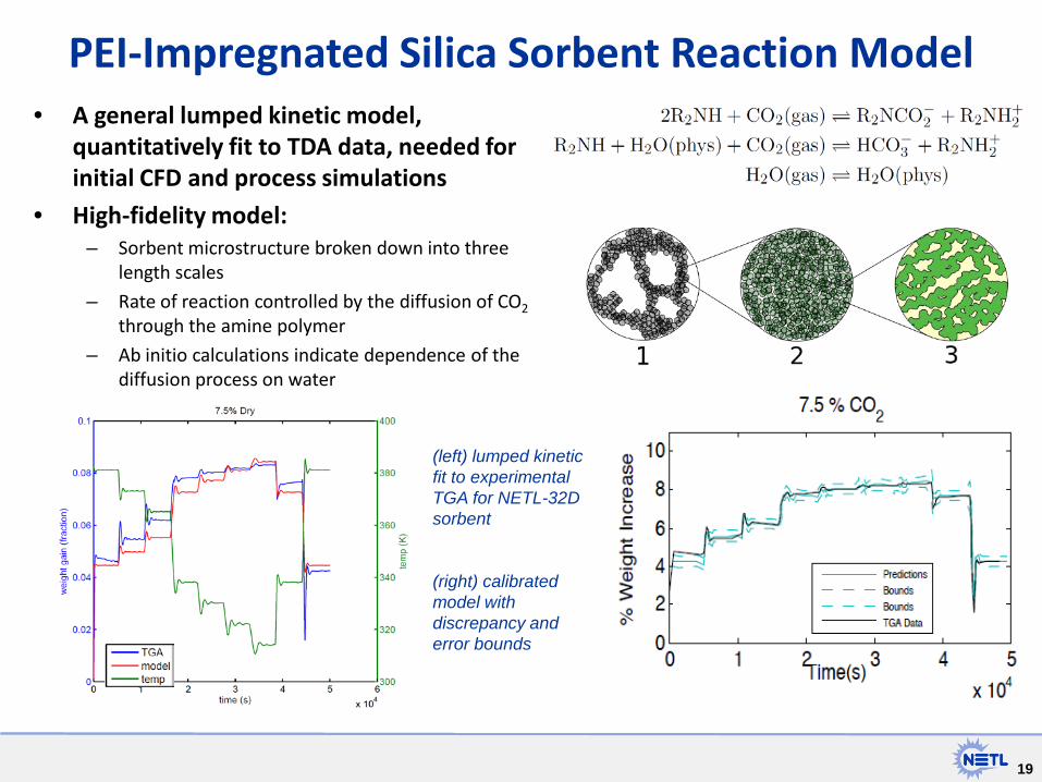
• A general lumped kinetic model, quantitatively fit to TDA data, needed for initial CFD and process simulations
• High-fidelity model: – Sorbent microstructure broken down into three
length scales
– Rate of reaction controlled by the diffusion of CO2 through the amine polymer
– Ab initio calculations indicate dependence of the diffusion process on water
PEI-Impregnated Silica Sorbent Reaction Model
(left) lumped kinetic fit to experimental TGA for NETL-32D sorbent (right) calibrated model with discrepancy and error bounds

20
Bayesian Methods in Parameter Estimation
• Experimental data tends to constrict the prior distribution, resulting in a experiment-based estimate influenced by theoretical calculations.
• A stochastic function representing the model error can also be estimated in this way.
Above: schematic of the calibration process. Left to right: draws from the prior, draws from the posterior, discrepancy, and predictions.
Right: model-plus-discrepancy (a) and model-only predictions (b), with confidence bounds.
Mebane DS, Bhat KS, Kress JD, Fauth DJ, Gray ML, Lee A, Miller DC., Bayesian calibration of thermodynamic models for the uptake of CO2 in supported amine sorbents using ab initio priors. Phys Chem Chem Phys. 15 (2013) 4355-66. doi: 10.1039/c3cp42963f.

21 21
CCSI Tools to develop an optimized process using rigorous models
Uncertainty Quantification
Superstructure Optimization (Determine Configuration)
Optimized Process
Simulation-Based Optimization
Process Models
Basic Data Submodels
Operating condition
Sys
tem
per
form
ance
Algebraic Surrogate Models
Miller, D.C.; Sahinidis, N.V.; Cozad, A.; Lee, A.; Kim, H.; Morinelly, J.; Eslick, J.; Yuan, Z. "Computational Tools for Accelerating Carbon Capture Process Development". In Proceedings of The 38th International Technical Conference on Clean Coal & Fuel Systems, Clearwater, FL, USA. June 2 to 6, 2013.

22 22
Solid Sorbent System Models Bubbling Fluidized Bed (BFB) Models
Flexible BFB models with immersed heat exchangers have been developed to be used as adsorber or regenerator, as needed, with varying locations for solids inlet and outlet streams Any number of BFB adsorbers and/or regenerators can be connected in series and/or in parallel depending on the user requirements A 2-stage adsorption model with customized variables suitable for incorporating UQ has been developed
Moving Bed (MB) Models External resistance to mass transfer has been modeled. This is particularly important in the regenerator model due to the high operating temperature. Heat exchanger model, mass and heat transfer coefficients, boundary conditions, temperature specifications, and properties models are revisited for better model accuracy.
23 23
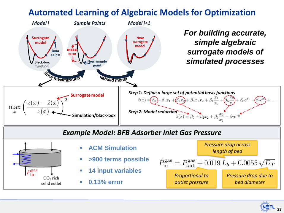
Automated Learning of Algebraic Models for Optimization
For building accurate, simple algebraic
surrogate models of simulated processes
Example Model: BFB Adsorber Inlet Gas Pressure
ACM Simulation
>900 terms possible
14 input variables
0.13% error
Pressure drop across length of bed
Proportional to outlet pressure
Pressure drop due to bed diameter
24 24
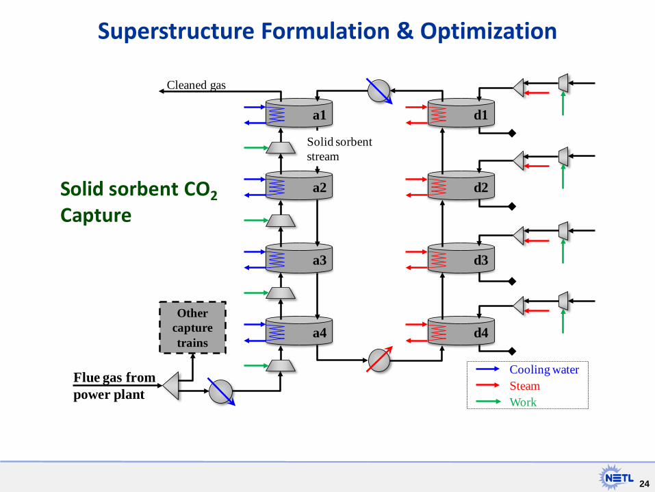
Superstructure Formulation & Optimization
Flue gas from power plant
a1
a2
a3
a4
d1
d2
d3
d4
Solid sorbent stream
Cleaned gas
Other capture trains
Cooling waterSteamWork
Solid sorbent CO2
Capture
25 25
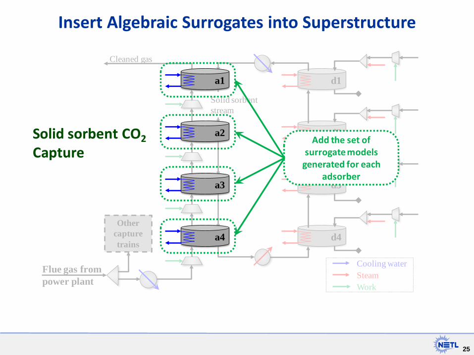
Insert Algebraic Surrogates into Superstructure
Flue gas from power plant
a1
a2
a3
a4
d1
d2
d3
d4
Solid sorbent stream
Cleaned gas
Other capture trains
Cooling waterSteamWork
Solid sorbent CO2
Capture
a1
a2
a3
a4
Add the set of surrogate models
generated for each adsorber
Solid sorbent CO2
Capture
26 26
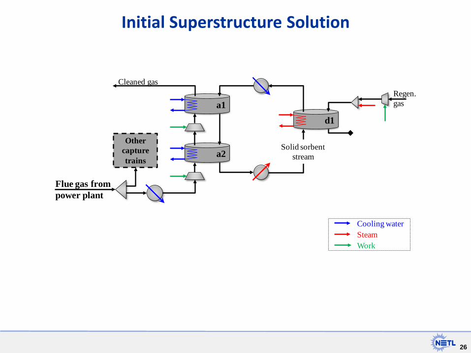
Initial Superstructure Solution
a1
Flue gas from power plant
a2
d1
Solid sorbent stream
Cleaned gas
Other capture trains
Regen.gas
Cooling waterSteamWork

27 27
Turbine Gateway (runs simulations and stores results
can run simulations in parallel)
Simulation-Based Optimization Framework
Graphical Interface
Optimization Engine
Derivative-free optimizer
Meta-flowsheet connects simulations in various software
Option for rigorous heat integration
Sam
ple
Poi
nts
Obj
ectiv
e Fu
nctio
ns
Miller, D.C.; Sahinidis, N.V.; Cozad, A.; Lee, A.; Kim, H.; Morinelly, J.; Eslick, J.; Yuan, Z. "Computational Tools for Accelerating Carbon Capture Process Development". In Proceedings of The 38th International Technical Conference on Clean Coal & Fuel Systems, Clearwater, FL, USA. June 2 to 6, 2013.;

28 28
Turbine Science Gateway
29 29
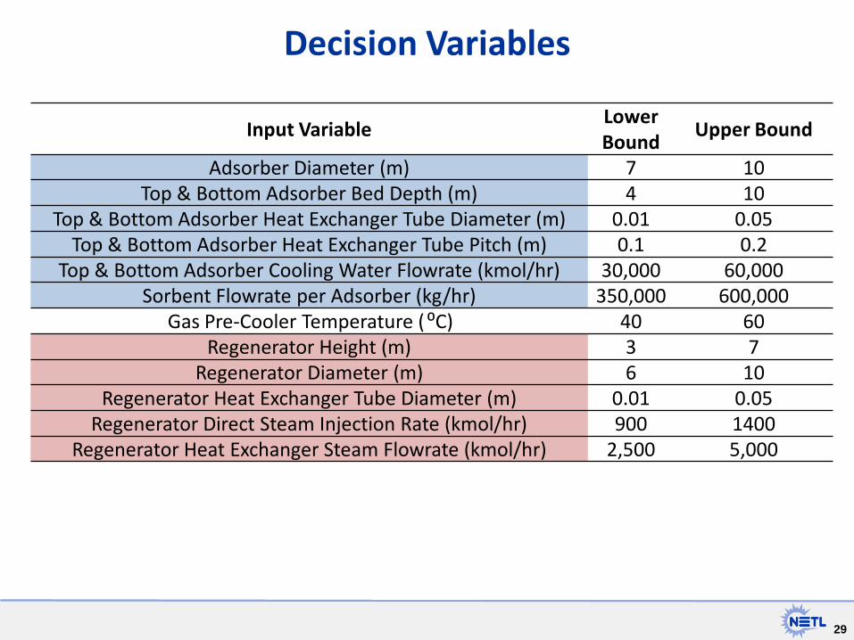
Decision Variables
Input Variable Lower Bound Upper Bound
Adsorber Diameter (m) 7 10 Top & Bottom Adsorber Bed Depth (m) 4 10
Top & Bottom Adsorber Heat Exchanger Tube Diameter (m) 0.01 0.05 Top & Bottom Adsorber Heat Exchanger Tube Pitch (m) 0.1 0.2
Top & Bottom Adsorber Cooling Water Flowrate (kmol/hr) 30,000 60,000 Sorbent Flowrate per Adsorber (kg/hr) 350,000 600,000
Gas Pre-Cooler Temperature (⁰C) 40 60 Regenerator Height (m) 3 7
Regenerator Diameter (m) 6 10 Regenerator Heat Exchanger Tube Diameter (m) 0.01 0.05
Regenerator Direct Steam Injection Rate (kmol/hr) 900 1400 Regenerator Heat Exchanger Steam Flowrate (kmol/hr) 2,500 5,000

30 30
Optimized Capture Process Developed using CCSI Toolset
∆Loading 1.8 mol CO2/kg
0.66 mol H2O/kg
Miller, D.C.; Sahinidis, N.V.; Cozad, A.; Lee, A.; Kim, H.; Morinelly, J.; Eslick, J.; Yuan, Z. "Computational Tools for Accelerating Carbon Capture Process Development". In Proceedings of The 38th International Technical Conference on Clean Coal & Fuel Systems, Clearwater, FL, USA. June 2 to 6, 2013.
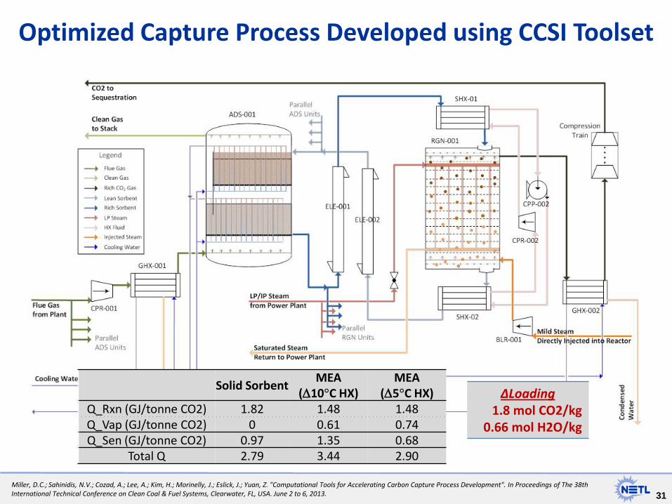
31 31
Optimized Capture Process Developed using CCSI Toolset
∆Loading 1.8 mol CO2/kg
0.66 mol H2O/kg
Miller, D.C.; Sahinidis, N.V.; Cozad, A.; Lee, A.; Kim, H.; Morinelly, J.; Eslick, J.; Yuan, Z. "Computational Tools for Accelerating Carbon Capture Process Development". In Proceedings of The 38th International Technical Conference on Clean Coal & Fuel Systems, Clearwater, FL, USA. June 2 to 6, 2013.
Solid Sorbent MEA (∆10°C HX)
MEA (∆5°C HX)
Q_Rxn (GJ/tonne CO2) 1.82 1.48 1.48 Q_Vap (GJ/tonne CO2) 0 0.61 0.74 Q_Sen (GJ/tonne CO2) 0.97 1.35 0.68
Total Q 2.79 3.44 2.90

32 32
Uncertainty Quantification: How certain are we that our model can predict the system performance accurately?
CCSI simulation
Risk analysis
How to quantify these error bounds a priori? How to reduce these bounds?
Operating condition
Sys
tem
per
form
ance
How does the uncertainty in the prediction affect the risk assessment outcome?
Scaled-up design

33 33
Multi-Scale Uncertainty Quantification Framework
Chemistry model
Bayesian inference
With model-form correction Sorbent
Process Model
Sorbent Process Model
Optimization & UQ Framework
Unified interface for UQ, steady-state RM, and optimization.
• UQ for basic data models – Bayesian UQ methodology – Integration of model form discrepancy into process & CFD models
• UQ for CFD models – Adaptive sampling capability for RM/UQ – Bayesian calibration capability – UQ of discrepancy between CFD/process models
• UQ for process models – Integration with optimization platform – Optimization under uncertainty
34 34
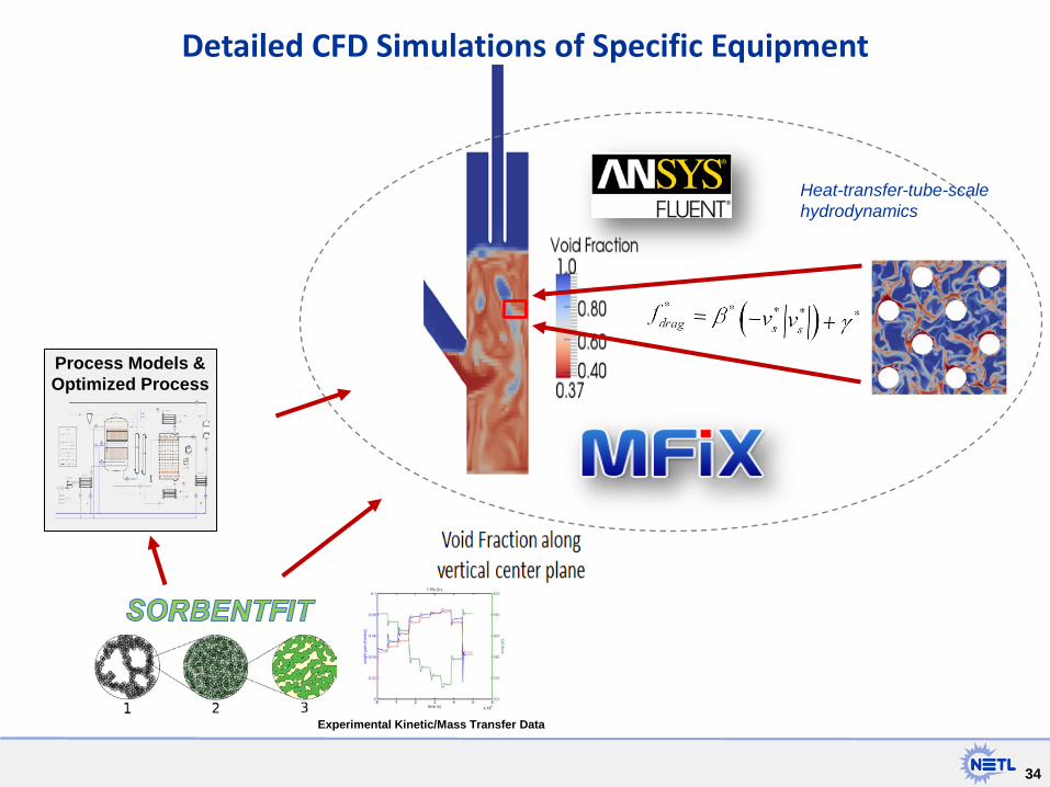
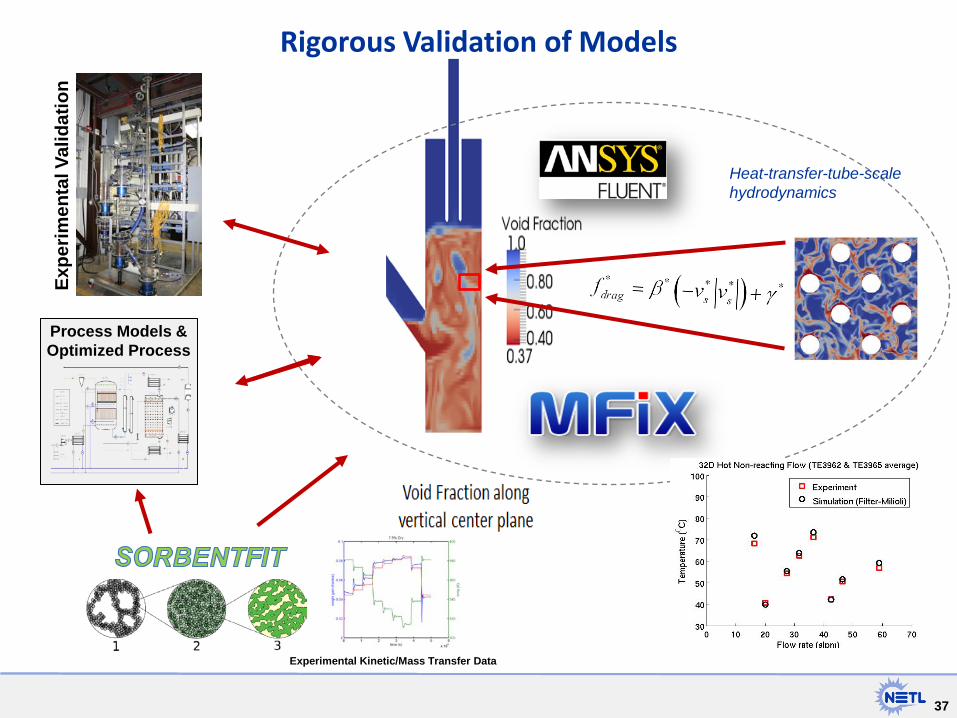
Detailed CFD Simulations of Specific Equipment
Heat-transfer-tube-scale hydrodynamics
Process Models & Optimized Process
Experimental Kinetic/Mass Transfer Data
35
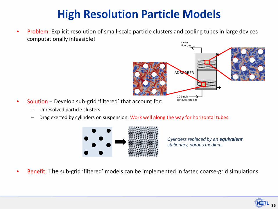
• Problem: Explicit resolution of small-scale particle clusters and cooling tubes in large devices computationally infeasible!
• Solution ‒ Develop sub-grid ‘filtered’ that account for: – Unresolved particle clusters.
– Drag exerted by cylinders on suspension. Work well along the way for horizontal tubes
• Benefit: The sub-grid ‘filtered’ models can be implemented in faster, coarse-grid simulations.
High Resolution Particle Models
Cylinders replaced by an equivalent stationary, porous medium.
36
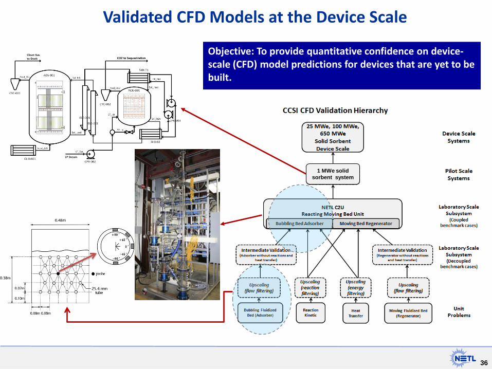
Validated CFD Models at the Device Scale
Objective: To provide quantitative confidence on device-scale (CFD) model predictions for devices that are yet to be built.
1 MWe solid sorbent system
37 37
Rigorous Validation of Models
Heat-transfer-tube-scale hydrodynamics
Expe
rimen
tal V
alid
atio
n
Process Models & Optimized Process
Experimental Kinetic/Mass Transfer Data
38
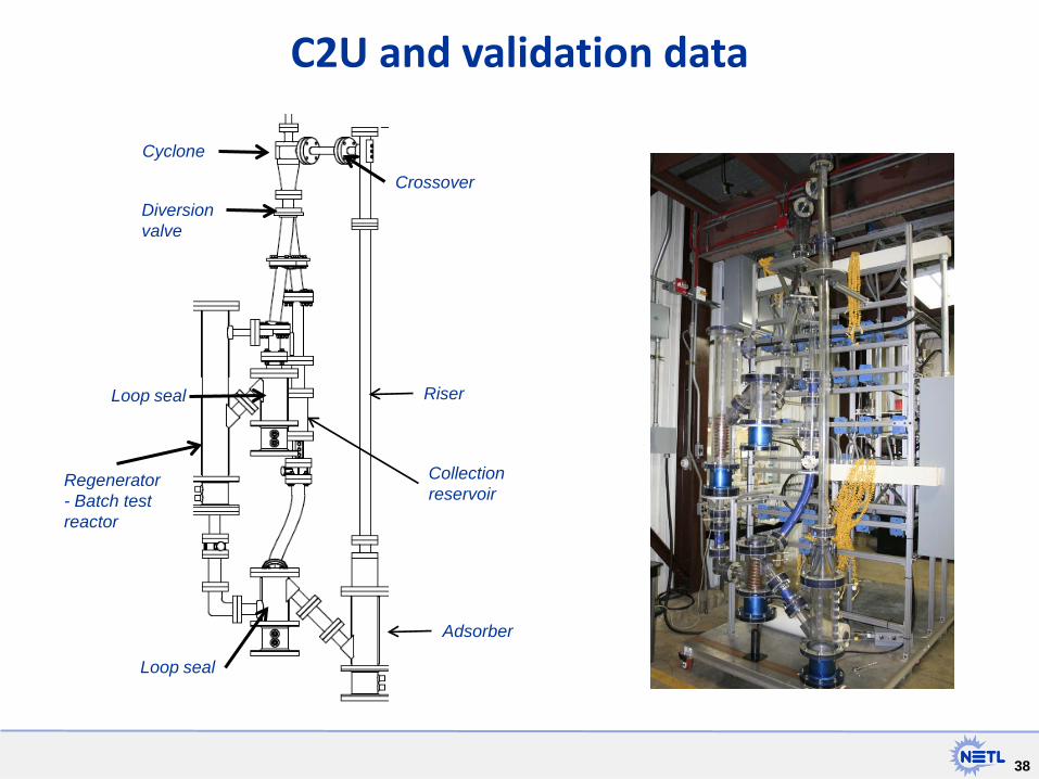
C2U and validation data
Adsorber
Riser
Crossover
Cyclone
Diversion valve
Loop seal
Loop seal
Regenerator - Batch test reactor
Collection reservoir
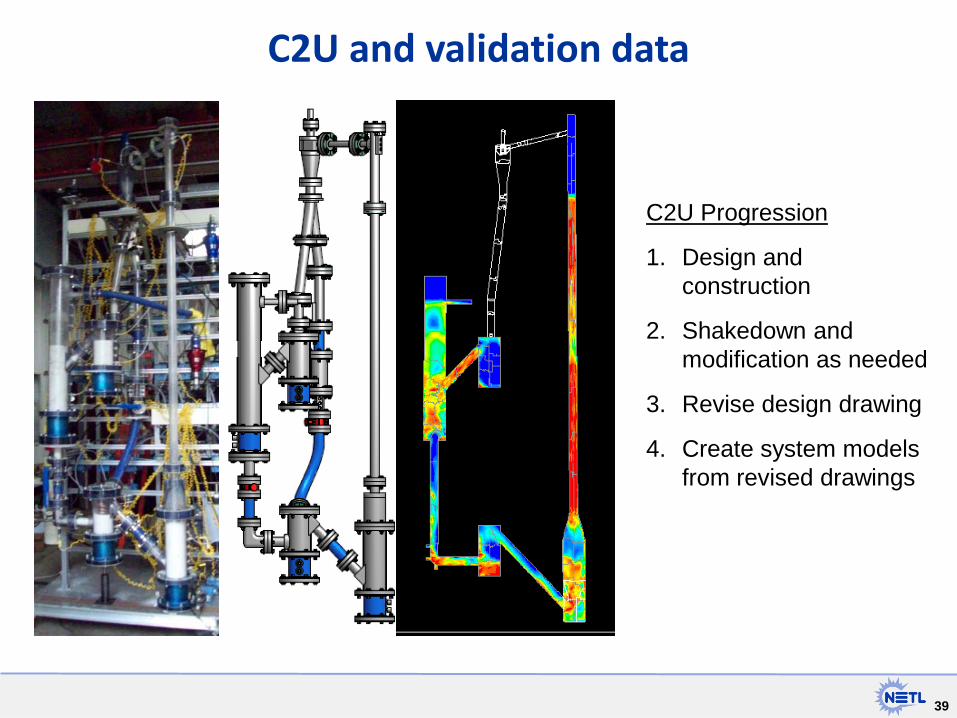
39
C2U and validation data
C2U Progression
1. Design and construction
2. Shakedown and modification as needed
3. Revise design drawing
4. Create system models from revised drawings
40
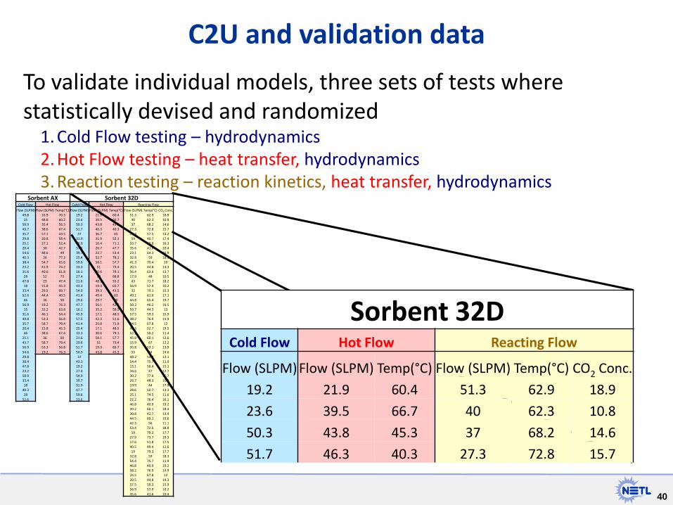
To validate individual models, three sets of tests where statistically devised and randomized
1. Cold Flow testing – hydrodynamics 2. Hot Flow testing – heat transfer, hydrodynamics 3. Reaction testing – reaction kinetics, heat transfer, hydrodynamics
C2U and validation data
Sorbent AX Sorbent 32D Cold Flow Hot Flow Cold Flow Hot Flow Reacting Flow
Flow (SLPM) Flow (SLPM) Temp(°C) Flow (SLPM) Flow (SLPM) Temp(°C) Flow (SLPM) Temp(°C) CO2 Conc. 49.8 16.9 70.3 19.2 21.9 60.4 51.3 62.9 18.9 15 48.8 60.2 23.6 39.5 66.7 40 62.3 10.8
58.9 35.4 56.3 50.3 43.8 45.3 37 68.2 14.6 43.7 38.6 67.4 51.7 46.3 40.3 27.3 72.8 15.7 35.7 57.1 43.5 37 36.7 65 23.3 57.5 14.2 29.8 20.8 58.4 31.9 31.9 52.1 59 40.7 17.4 25.1 27.1 52.4 45.9 16.4 71.1 33.7 69.8 16.3 20.4 30 42.7 57.5 26.7 47.7 35.6 41.6 10.4 54.6 48.6 49 39.7 22.7 53.4 23.1 64.3 16.9 40.3 26 77.2 25.4 52.7 78.1 32.8 59 18.3 38.4 54.7 65.6 59.6 58.1 57.7 41.3 70.4 20 23.2 41.9 74.2 33.3 51 73.4 20.5 44.8 14.3 31.6 40.6 61.8 16.1 30.6 79.1 56.4 63.6 13.7 28 52 73 27.4 59 68.8 17.9 48 10.5
47.8 23 47.4 21.6 48.1 55.2 43 71.7 18.2 18 15.8 45.3 43.3 19.3 65.7 56.9 57.9 10.2
33.4 29.5 69.7 54.9 39.3 43.5 32 79.1 15.3 52.6 44.4 40.5 41.4 49.4 63 49.1 61.6 17.1 46 36 50 29.6 29.7 76 44.8 65.4 19.7
56.9 19.2 76.3 47.7 56.1 42.6 50.2 46.2 16.5 15 32.2 63.8 16.1 35.2 58.5 59.7 44.3 13
31.6 46.1 54.4 45.9 17.1 48.5 57.5 59.3 15.9 49.8 53.3 56.8 57.5 42.3 51.6 38.2 76.9 14.9 35.7 58.7 79.4 41.4 25.8 71.9 24.5 67.8 12 20.4 15.8 45.3 25.4 17.1 48.5 49.3 52.7 19.5 46 38.6 67.4 33.3 30.6 79.1 52.2 50.2 11.4
25.1 36 50 21.6 58.1 57.7 45.9 60.1 12.6 43.7 58.7 79.4 29.6 51 73.4 15.9 67 12.2 56.9 53.3 56.8 51.7 19.3 65.7 35.8 53.1 13.9 54.6 19.2 76.3 50.3 43.8 45.3 55 54 14.6 29.8 37 48.2 54.9 13.1 38.4 43.3 54.4 75.7 11.9 47.8 19.2 15.1 56.4 15.1 23.2 27.4 34.6 47 12.7 58.9 54.9 30.2 77.6 16.7 33.4 39.7 26.7 48.3 10.8 18 31.9 19.9 44 17.9
40.3 47.7 28.6 50.7 13.3 28 59.6 25.1 74.5 11.6
52.6 23.6 22.2 76.4 16.1 46.8 40.9 19.2 39.2 66.1 18.4 30.8 42.7 13.4 44.5 69.1 15.6 42.3 56 11.1 53.4 72.5 18.8 19 79.3 17.7
27.9 73.7 19.3 17.6 51.8 17.5 40.5 49.4 11.6 19 79.3 17.7
32.8 59 18.3 54.4 75.7 11.9 46.8 40.9 19.2 38.2 76.9 14.9 24.5 67.8 12 20.5 44.8 14.3 57.5 59.3 15.9 56.9 57.9 10.2 35.6 41.6 10.4
Sorbent 32D Cold Flow Hot Flow Reacting Flow
Flow (SLPM) Flow (SLPM) Temp(°C) Flow (SLPM) Temp(°C) CO2 Conc.
19.2 21.9 60.4 51.3 62.9 18.9
23.6 39.5 66.7 40 62.3 10.8
50.3 43.8 45.3 37 68.2 14.6
51.7 46.3 40.3 27.3 72.8 15.7

41
35
50
65
80
95
110
125
-1.0
0.0
1.0
2.0
3.0
4.0
5.0
23300 23800
Bed
Tem
pera
ture
(°C)
CO2
adso
rpti
on (s
lpm
)
Time (s)
Regeneration - BIAS
CO2
Bed temp- TE3962A
35
50
65
80
95
110
125
-1.0
0.0
1.0
2.0
3.0
4.0
5.0
19200 19700 20200 20700 21200
Bed
Tem
pera
ture
(°C)
CO2
adso
rpti
on (s
lpm
)
Time (s)
Adsorption-BIAS
CO2
Bed temp- TE3962A
C2U Initial testing data
35
50
65
80
95
110
125
-5.0
-4.0
-3.0
-2.0
-1.0
0.0
1.0
21300 21800 22300 22800 23300
Bed
Tem
pera
ture
(°C)
CO2
ads
orpt
ion
(slp
m)
Time (s)
Transition to Regeneration - BIAS
CO2
Bed temp- TE3962A
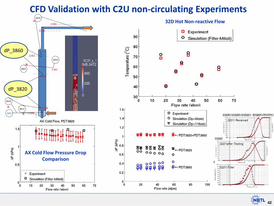
Batch test conducted in the regenerator with the BIAS sorbent
Most CO2 is released before achieving the regeneration temperature
42
32D Hot Non-reactive Flow
CFD Validation with C2U non-circulating Experiments
AX Cold Flow Pressure Drop Comparison
1.378
2.457
3.092
3.016
1.937
1.848
1.518
2820
3860
H
3870H
3801
H
3812
H
3820
H
3830
H
3805
H
dP_3820
dP_3860

43 43
• Coupling experimental development with simulation enables – New approaches to be screened more quickly – Focuses development on most promising material and
process conditions • Simulation with uncertainty quantification
– Focuses experimental efforts on elements with the most impact to the process/technology
• Focused experiments for model validation enable – Lower risk for scale up through quantitative confidence of
model predictions
Conclusion
44
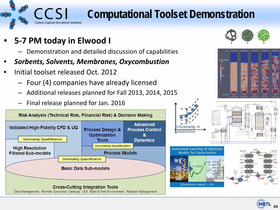
• 5-7 PM today in Elwood I – Demonstration and detailed discussion of capabilities
• Sorbents, Solvents, Membranes, Oxycombustion • Initial toolset released Oct. 2012
– Four (4) companies have already licensed – Additional releases planned for Fall 2013, 2014, 2015
– Final release planned for Jan. 2016
Computational Toolset Demonstration