Embed Size (px)
Citation preview
Accelerated Corrosion Tests of Nuclear Reactor Pressure Vessel Materialsin NaClH3BO3 Solutions+1
Hiroyuki Kaneko+2, Tokiko Nakagawa, Kousei Hiraizumi+3 and Ryo Sakai+4
Department of Materials Science and Engineering, Graduate School of Engineering and Resource Science,Akita University, Akita 010-8502, Japan
Following the 2011 accident at the Fukushima Daiichi nuclear power station, sea water for cooling and boric acid for maintaining a non-critical condition, both corrosive liquids, were injected into nuclear pressure vessels. In order to estimate corrosive characteristics of the pressurevessels an experimental study was undertaken to provide an accelerated corrosion test on SA533B low alloy steel and Inconel 600, materialsused in the construction of the pressure vessels. In a typical experiment, samples of these materials were immersed in saturated NaCl andconcentrated H3BO3 aqueous solutions at a temperature of 423K. SA533B suffered little or no corrosion in saturated NaCl solution, significantcorrosion in concentrated H3BO3 solution and substantial corrosion in the binary saturated NaCl-concentrated H3BO3 solution. Galvaniccorrosion of SA533B was accelerated when Inconel 600 was also immersed in the same solution and the two samples were electricallyconnected either externally by a wire lead or internally by a screw made of SA533B or both. Corrosion rate in the initial stage was 0.07mm perhour. The corrosion product on SA533B was porous and easily detachable, indicating corrosion to be progressive without producing a stableprotective corrosion layer. The validity of the extreme experimental condition for accelerated corrosion tests is discussed and experimentalprograms for further investigation are proposed. [doi:10.2320/matertrans.M2012405]
(Received December 10, 2012; Accepted March 1, 2013; Published April 25, 2013)
Keywords: nuclear accident, boiling water reactor, galvanic corrosion, crevice corrosion, SA533B
1. Introduction
On 11th March 2011, a nuclear disaster of Level 7 (INES:International Nuclear Event Scale) occurred at the FukushimaDaiichi nuclear power station of the Tokyo Electric PowerCompany. As a result, cooling of three reactor pressurevessels became almost impossible. An analysis by the TokyoElectric Power Company1) estimated that the vessels wouldhave been seriously damaged due to the meltdown ofcontaining nuclear fuels.
The Nuclear and Industrial Safety Agency2) also an-nounced that sea water for cooling and ‘boric acid’ formaintaining a non-critical condition were being injected intothe vessels as emergency measures, although it is not clear atpresent whether the announced ‘boric acid’ was pure boricacid or a boric compound such as sodium pentaborate.Sodium chloride contained in seawater and boric acid arestrongly corrosive reagents towards nuclear vessel materials.As a result, the possibility of serious corrosion of vesselmaterials during a long-term maintenance period prior to theirdecommissioning must be carefully considered, althoughcooling water was changed from seawater to light water laterin the process.
Even now, there is still insufficient information on thecorrosion of reactor pressure vessel materials exposed tosevere accidental conditions. In the case of the Three MileIsland nuclear accident in 1979, which was of Level 5, avessel containing nuclear fuels suffered partial melt-down butwas not destroyed3) and seawater was not injected into thevessel. However, it is well known that vessel materials areseverely corroded by boric acid. In the case of the David-
Besse pressurized water reactor in 2002, a hole wasdiscovered in the head of the vessel and it was verified thatit was due to the invasion of boric acid injected forcontrolling neutron flux to the low alloy steel vessel itselfvia a crevice with Inconel cladding.4) After this accident,thorough laboratory experiments were carried out.5) As atypical example, a high corrosion rate of 40mm/year wasobserved in aerated concentrated H3BO3 at 370.5K.
The nuclear reactors involved in the accident at theFukushima Daiichi nuclear power station are of the boiling-water type; the vessels themselves are made of low alloy steeltogether with stainless steel cladding inside a large part of thevessels. A cladding of nickel-based super alloy is incorpo-rated inside a part of the bottom of the vessels and welded tothe sheaths of the control rods. Therefore, if cladding mate-rials of the vessels are damaged and outer steel is exposed tocoolant, corrosion of steel proceeds. In addition, if a galvaniccouple is formed between steel and corrosion-resistantcladding material, galvanic corrosion is likely to occur. Thepossibility of such corrosion has not yet been discussed.
Therefore, our purpose in this study is to investigate thenature of the corrosion process and its rate according to thefollowing procedures. The first is to make a model of thedamaged vessel in a corrosive coolant environment. Thesecond is to choose appropriate experimental conditions foraccelerated corrosion testing. The third is to determine theresults of accelerated corrosion tests. Finally, some recom-mended experimental projects for future investigation areproposed.
2. Proposal of a Model of the Vessel for AcceleratedCorrosion Test
Reactors subject to the accident, units 1, 2 and 3 are of theboiling-water type. Reactors, units 1, 2 and 3 were madeduring different periods but are treated generally withoutconsidering this difference in this study.
+1This Paper was Originally Published in Japanese in J. Japan Inst. Metals76 (2012) 615623.
+2Corresponding author, E-mail: [email protected]+3Undergraduate Student, Akita University. Present address: Akita BranchOffice, East Japan Railway Company, Akita 010-0001, Japan
+4Undergraduate Student, Akita University
Materials Transactions, Vol. 54, No. 5 (2013) pp. 755 to 764©2013 The Japan Institute of Metals and Materials

In Fig. 1, schematic diagrams of the vessel are shown. InFig. 1(a), a diagram of the usual vessel is shown. Detaileddiagrams of vessels are shown in a government report.6) Ingeneral, a reactor is made of low alloy steel 1516 cm thick,and is internally clad with corrosion-resistant materials suchas stainless steel and nickel-based super alloy to preventcorrosion. Degradation of the vessel material is checked byinserting surveillance test specimens with the same compo-sition into the vessel.7)
The most important matters are degradation of materials bystrong neutron radiation and generation of stress corrosioncracking and if it is found that cladded materials are notdestroyed, it is concluded that there is no severe corrosion ofthe vessel material in a short time.
On the other hand, there is insufficient informationregarding the present situation of vessels involved in theaccidents. According to an analysis by Tokyo Electric PowerCompany,1) nuclear fuels in the unit 1 reactor dropped downinto the containment vessel from the pressure vessel. In site 2and 3 reactors, melt-down fuel remains in the pressurevessels. Although the situation depends upon whether athrough-hole in the vessels exists or not, it is possible thatwelded parts of control rods are easily destroyed.
Therefore, a model of a damaged vessel is shown inFig. 1(b). It is postulated that a part of the welded nickel-based super alloy was destroyed and low alloy steel wasdirectly exposed to coolant; also a through-hole wasgenerated so that a galvanic couple was formed betweenthe welded nickel-based super alloy and the steel. If melt-down fuel remains at the bottom of the vessel, vessel materialundergoes local heating by decay products and is highlyactivated by strong nuclear radiation. In addition, at hightemperature and high pressure, injected seawater and boricacid are concentrated by boiling the coolant. After this,although cooling was attempted, melt-down fuels provide astrong source of heat, resulting in exceptionally corrosivecircumstances for vessel materials.
3. Experimental Conditions for Accelerated CorrosionTest
Although a simple model of the damaged vessel ispresented in Fig. 1(b), there is almost no reliable informationon the present situation as yet. It is important that a decision
be made urgently concerning what experiments should bedone involving appropriate experimental conditions forinvestigating the possible corrosion of the vessel materialseven where there is almost no information without waitinguntil sufficient information becomes available. In order toinvestigate the possibility of unexpectedly severe corrosion,experimental conditions for accelerated corrosion test areproposed in some detail below. Of course, test materials andchemical constituents of test solutions should resemble asclosely as possible those pertinent to the accident includingchemical substances in coolants during the period of theaccident. On the other hand, experimental parameters such astemperature, applied pressure, concentrations of chemicalsubstances and so on, should be chosen so as to be suitablefor accelerated corrosion tests. Once experimental results atan appropriate experimental condition are obtained, it isexpected that experimental parameters will be modified stepby step in response to more realistic conditions, as soon asnew reliable information on the vessel situation becomesavailable.
As a test vessel material, a modified low alloy steel,SA533B, used at present as vessel material was chosen,because it is not easy to obtain the material which has thesame chemical compositions as the original vessel materialsubjected to the accident, and furthermore the present com-mercially available material is useful for further investigation.
In Table 1, chemical compositions of the materials usedare shown. As a heat treatment, a SA533B plate 55mm thick,was quenched after holding at 1153K for 0.6 ks, and beingtempered at a rate of 1.8 ks/25mm at 923K. As a reference,some chemical compositions of the vessel material of thedamaged Unit 1 reactor are also shown.8) According to areview on the improvement of vessel materials by Kodaira,9)
concentrations of copper, phosphorus and sulfur, especiallycopper were decreased in order to obtain purified materialsappropriate to those used around the year of 1973. But, thevessel material of Unit 1 reactor was made even earlier.For example, Takeuchi et al.10) investigated the influence ofchemical compositions on neutron irradiation embrittlementof vessel material. Also, from the standpoint of corrosion, thecopper content can act as a local cathode, resulting in agalvanic corrosion by forming a galvanic couple with ironin low alloy steel.11) Therefore, employing a presently usedlow alloy steel with reduced copper concentration means itscorrosion is expected to be less than that of the steel subjectto the accident. Nevertheless, as shown later, even the presentlow alloy steel corrodes very severely.
As a reference material for comparing the corrosioncharacteristic, pure iron was chosen, because pure iron ismore easily obtainable, and comparison of the corrosioncharacteristic is very important allowing the contribution ofadded elements in the steel to be assessed. Stainless steel isused as cladding inside most parts of the steel comprising thevessel. A cladding of nickel-based super alloy is incorporatedon the inside of the base of the steel and welded to the sheathsof the controlling rods. Although the possibility of destructionof the stainless part is not negligible, nickel-based superalloy part-welded to the sheaths of the controlling rods isliable to be destroyed. Therefore, as a test specimen inaddition to SA533B, a typical nickel-based super alloy,
Through hole
Stainless steel(clad)
Low-alloy steel
Melted nuclear fuelHigh radioactivityHigh temperature source
CoolantSeawaterBoric acid
Nickel based superalloy(weld metal)
Recirculatingwater inlet
steam
Crack
Steam outlet
Shroud
Coolant inlet
Control rods Fuel
steam
Steam separator
(a) (b)
Fig. 1 Schematic diagrams of boiling water reactor pressure vessel: (a) adiagram of the usual vessel and (b) a model of the damaged vessel.
H. Kaneko, T. Nakagawa, K. Hiraizumi and R. Sakai756

Inconel 600 was chosen. The specimen used in this study isexpressed as Ni16Cr7Fe according to its principal chemicalcompositions shown in Table 1. The corrosion characteristicof Inconel 600 used as a nuclear material is well known.12)
Seawater was injected as an emergency coolant at thebeginning of the accident. “Boric acid” was also sometimesinjected in order to maintain the non-critical condition. Ingeneral, boric acid, H3BO3 (acidic in nature for pressurizedwater reactors), and sodium pentaborate, NaB5O8·5H2O(basic in nature for boiling water reactors) are used. Sodiumpentaborate, NaB5O8·5H2O is a compound of borax,Na2B4O7·10H2O and boric acid, H3BO3. But, it is not clearwhat kind of ‘boric acid’ was injected in the emergency.
By considering that a main component of injected seawateris 3mass% NaCl, it is reasonable that the coolant solutionshould mainly be treated as the system NaClH3BO3Na2B4O7. There are some causes expected to lower the pHof the coolant. The pH of sodium pentaborate decreases withincreasing concentration, reaching the almost neutral valueof 6.8 at 14mass%.13) UO2
2+ ions generated from melteduranium fuel react with H2O, to lower the pH, according tothe following reaction: UO2
2þ þ H2O ¼ UO3 þ 2Hþ:Anyway, it is reasonable to suppose that it was not easy to
maintain stable chemical compositions and pH of the coolantinside the vessel during the duration of the severe accident.In this study, as an extremely acidic condition, a test solutionof the NaClH3BO3 system was prepared.
Temperature was set at 423K for two reasons. Accordingto a report of Tokyo Electric Power Company,1) hightemperatures above 473K continued in the beginning of theaccident for units 1, 2 and 3 reactors, and were above 373Keven after 2 months. However, from a reference,5) corrosionrate of SA533B in a saturated H3BO3 solution at 298K,decreases above 423K. Therefore, a temperature of 423Kwas chosen for an accelerated corrosion test by judgingthat experiments above 423K are not always appropriate.To investigate temperature dependence on the corrosion,experiments were also carried out at 298 and 373K.
A main test solution was a NaClH3BO3 mixed solution,and also both a NaCl solution and a H3BO3 solution wereused as references. In Table 2, chemical compositions ofsolutions are shown. The amounts of H2O were fixed at25.00 g in all three solutions in this study. Concentrations aremeasured using the unit of molality, mol/kg H2O. Solubilitiesof NaCl14) in a NaCl solution and H3BO3
15) in a H3BO3
solution are curve-fitted data obtained from the reference.Mutual solubilities of NaCl and H3BO3 in the mixed solutionare not shown, because there is insufficient information onthe mutual solubilities. Corresponding to the condition ofinsufficient cooling during the accident at high temperatureand high pressure, NaCl is set up so as to be saturated at anytemperature measured. H3BO3 is saturated at temperaturesbelow 373K, but, is adjusted so as to become moreconcentrated, but not saturated at 423K. Solubility ofH3BO3 is very high at 423K, and saturated solution at423K has a low mole ratio of H2O/H3BO3, resulting ininsufficient water for full ion-solvation. It is therefore notappropriate to investigate corrosion in such a solution, sothat the use of the saturated condition was not attempted. Inaddition, a reference4) shows that when the amount of H2Ois substantially decreased, contrarily corrosion decreases. ThepH of the mixed solution was 3.23 at 298K.
In Table 2, the effect of mutual solubilities is not shown,but a reference16) including mutual solubilities of NaCl andH3BO3 in mixed solutions at 303373K, shows saturatedconcentrations are 7.149mol/kg for NaCl and 6.797mol/kgfor H3BO3 at 373K.
Although possible irradiation effects on the corrosion ofthe materials should be investigated, such an experiment cannot be carried out in a standard laboratory. Therefore, anyirradiation effect on the materials is out of consideration inthis study. But, hydrogen, oxygen and hydrogen peroxidecan be generated by the radiohydrolysis of water due to themelted nuclear fuel.3) The effect of oxygen generated byradiohydrolysis is examined by experimenting with oxygenat high pressure in this study.
4. Experimental
Apparatuses used in this study are the same as those usedfor investigating the galvanic corrosion of a FeZn coupleat high temperature and high pressure by one of the presentauthors.17) Experimental procedures in this study are similarunless otherwise described. A specimen, 3.5 cm long, 1 cmwide with a given thickness was cut and polished withprogressively finer emery paper finishing with a grade of 800,and then washed with acetone. The specimen was covered
Table 1 Chemical compositions of materials.
Low alloy steel (SA533B):
Element Fe C Si Mn P Cu Ni Cr Mo S
Composition(mass%)
(Bal.) 0.19 0.23 1.41 0.003 0.01 0.65 0.16 0.57 0.00
Fukushimareactor
® ® 0.29 ® 0.020 0.23 0.55 ® ® ®
Ni16Cr7Fe alloy (Inconel 600):
Element C Si Mn P S Cu Ni Cr Fe
Composition(mass%)
0.04 0.01 0.24 0.008 0.001 0.07 76.05 15.75 7.02
Pure iron: Fe > 99.99%
Table 2 Chemical compositions of solutions.*1
NaCl H3BO3 H2O
Amount 20.00 g 20.00 g 25.00 g
Maximumconcentration
13.7mol/kg 12.9mol/kg
423K7.23mol/kg
(Saturated concentration)12.9mol/kg*2
373K6.71mol/kg
(Saturated concentration)6.15mol/kg
(Saturated concentration)
298K6.14mol/kg
(Saturated concentration)0.93mol/kg
(Saturated concentration)
*1Three solutions with the same amount of H2O were prepared: 20.00 gNaCl and 20.00 g H3BO3 in 25.00 g H2O (as a NaClH3BO3 solution);20.00 g NaCl, in 25.00 g H2O (as a NaCl solution); 20.00 g H3BO3 in25.00 g H2O (as a H3BO3 solution).*2At 423K, the maximum concentration (12.9mol/kg) of H3BO3 islower than the saturated concentration (19.4mol/kg).
Accelerated Corrosion Tests of Nuclear Reactor Pressure Vessel Materials in NaClH3BO3 Solutions 757

with Teflon tape except for an area on each side of 1 cm ©2 cm. After the immersion experiment, the part of thespecimen covered with Teflon was checked and found notto be corroded. This fact indicates that insulation of thespecimen except for the exposed surface area is sufficient.The specimen was connected with a rod (lead) made of thesame material by a screw made of acryl resin, and set up in anautoclave.
The autoclave was set up so that the specimen was hanginginto the solution inside a glass beaker with a volume of70mL. When the specimen was inserted into the solution, thelower part of the specimen was inserted into the region whereinsoluble NaCl and H3BO3 remained at the bottom of thebeaker, but there was no apparent difference between thecorrosion characteristics of the specimen observed. The testsolution was degassed by a flow of nitrogen gas and whenthe temperature reached 363K, the flow of nitrogen gas wasstopped and the stopcocks of the gas inlet and outlet wereclosed. When the temperature reached 373K, the stopcock ofthe gas outlet was opened for an instant to release residualnitrogen and then the stopcock was closed to retain watervapor within the autoclave. An experiment at 373K wascarried out at this condition. For the experiments at 423K, thetemperature was increased after this. It took about 1.2 ks toheat and cool from room temperature to 423K. In addition,an experiment at a total applied pressure of 2MPa was carriedout by applying oxygen. In the case of this experiment, inorder to avoid an abrupt increase of temperature by injectingoxygen due to adiabatic compression, a total pressure of1.7MPa was attained by applying oxygen when the temper-ature reached 393K, and then, to keep the applied pressureat 2MPa oxygen was applied at 423K. An experiment wasthen carried out using this pressured oxygen condition.
Electrochemical experiments, such as measurements ofelectrode potential and current, polarization measurement,galvanic potential and current were carried out. As areference electrode, a Ag·AgCl electrode was used. Surfaceobservation of the specimens was carried out using an opticalmicroscope and EPMA.
5. Results
Experiments were done according to experimental con-dition proposed in the previous section, that is, at 423K in aNaClH3BO3 mixed solution for 14.4 ks (4 h) unless other-wise described.
In Fig. 2, electrode potentials for specimens used in thisstudy are shown. Potentials versus Ag·AgCl electrode werestable until reaching about 10 ks. The potentials are about¹0.30V for Ni16Cr7Fe alloy, ¹0.45V for SA533B and¹0.55V for pure iron. The potential of Ni16Cr7Fe alloy isthe most positive among the specimens measured, and that ofiron is the most negative. Therefore, iron and SA533B canbecome anodic and Ni16Cr7Fe alloy cathodic, indicatinggalvanic corrosion of iron or SA533B will proceed whencoupled with Ni16Cr7Fe alloy. The difference of electrodepotential between coupled specimens indicates that galvaniccorrosion of iron can be more remarkable than that ofSA533B. After about 10 ks had elapsed, the electrodepotential of Ni16Cr7Fe alloy became unstable with time.
Also, the electrode potential of Fe transferred toward thenoble direction with time, and as a result a reversal ofpotential can occur. Reversal of electrode potential wasobserved for Fe/Ni16Cr7Fe and SA533B/Ni16Cr7Fecouples when the time exceeded around 14.4 ks, althoughlong term experiments were not intended in this study.
In Fig. 3, the results of polarization measurements forSA533B and Ni16Cr7Fe alloy are shown. Reproducibilityof measurements, especially that of Ni16Cr7Fe alloy waslacking. The solution used is a weak acid, pH ranging from3 to 4. Therefore, it is considered for SA533B that cathodicreactions are both the generation of hydrogen and reductionof dissolved oxygen, and the anodic reaction is dissolutionof iron contained in SA533B. Reaction mechanisms arediscussed later.
The cathodic reaction on Ni16Cr7Fe alloy is similarto that on SA533B. Corrosion current density for SA533Bobtained by extrapolating measured anodic and cathodicpolarization curves is about 500A·m¹2, that is, a corrosionrate of 0.07mm/h assuming that the corrosion rate isindependent of time. The potential difference betweenSA533B and Ni16Cr7Fe alloy is less than 200mV, andin the case of a galvanic couple, the cathodic current onNi16Cr7Fe alloy is not negligible. By considering that theanodic current of SA533B is equal to the sum of cathodiccurrent densities on SA533B and Ni16Cr7Fe alloy,
-1
-0.9
-0.8
-0.7
-0.6
-0.5
-0.4
-0.3
-0.2
-0.1
0
0 2 4 6 8 10 12 14
Pot
enti
al, E
/V v
s A
g · A
gCl
Time, t/ ks
Fe
Ni-16Cr-7Fe alloy
SA533B
Fig. 2 Open-circuit potentials for SA533B, Ni16Cr7Fe alloy and Fe.
1
10
100
1000
10000
-0.8 -0.7 -0.6 -0.5 -0.4 -0.3 -0.2 -0.1 0
Cur
rent
Den
sity
, i/A
·m-2
Potential, E/V vs Ag ·AgCl
Galvanic couple− 0.350 V 600 A ·m-2
Total cathodic current
Ni-16Cr-7Fe alloySA533B
Open circiut− 0.40 V500 A·m-2
Fig. 3 Polarization curves obtained at a sweep rate of 0.5mV/s forSA533B and Ni16Cr7Fe alloy.
H. Kaneko, T. Nakagawa, K. Hiraizumi and R. Sakai758

corrosion current density of SA533B is estimated to be about600A·m¹2, that is, a corrosion rate of 0.08mm/h. In thiscase, the contribution of the galvanic couple is estimatedto be about 100A·m¹2. The corrosion of SA533B itself isremarkable and is accelerated by the formation of a galvaniccouple. However, the reproducibility of polarization measure-ments is low and an analytical value has a considerableerror, because there is some uncertainty in the extrapolationmethod.
In Fig. 4, galvanic corrosion currents of a couple ofSA533B and Ni16Cr7Fe alloy measured by two methodsare shown: one is with a continuous connection and theother one minute on-off cycling. Both the current profilesare essentially similar to each other, although the currentmeasured by on-off cycling is a little larger than with acontinuous connection.
In Fig. 5, electrode potential corresponding to Fig. 4(b) isshown. Potentials of SA533B and Ni17Cr6Fe alloy weremeasured alternately at intervals of ten minutes. SA533B waspolarized anodically by about 20mV by coupling with Ni16Cr7Fe alloy, indicating that the corrosion characteristic ofthe couple is cathodically controlled. Anodic current densityat the anodically polarized potential of 20mV, as shownin Fig. 3, is 30A·m¹2, which is in good agreement with40A·m¹2 measured in the initial stage of the galvaniccoupling.
The effects of several experimental factors on the galvaniccorrosion of the SA533B/Ni16Cr7Fe alloy couple wereinvestigated, as shown in Figs. 6 to 9.
In Fig. 6, a comparison of corrosion between two kinds ofgalvanic couples, is shown. The galvanic current for Fe/Ni16Cr7Fe alloy is significantly larger than that for SA533B/Ni16Cr7Fe alloy, which corresponds to the fact that thepotential difference between iron and Ni16Cr7Fe alloy islarger than that between SA533B and Ni16Cr7Fe alloyas shown in Fig. 2. Galvanic current density for SA533B/Ni16Cr7Fe alloy is about 40A·m¹2 in the initial stage andthen decreases with time, the average value for 14.4 ks beingabout 5A·m¹2. On the other hand, the current density forFe/Ni16Cr7Fe alloy was 200A·m¹2 in the initial stage,leading to a stable value of about 30A·m¹2 after an extendedperiod. Calculated galvanic corrosion rate is 0.004mm/h, or3.4 cm/y, showing that the contribution of galvanic corrosionis certainly not negligible.
In Fig. 7, comparison of galvanic potential and current ofthe SA533B/Ni16Cr7Fe alloy couple for the three kinds ofsolutions is shown. A very low value of 0.04A·m¹2 in NaClsolution, but high values, 1A·m¹2 in H3BO3 solution and5A·m¹2 in mixed solution, respectively, were obtained. Whysuch a difference exists, will be discussed later. The galvanicpotential in each solution was relatively stable during themeasuring period.
0
10
20
30
40
50
60
70
0 2 4 6 8 10 12 14
Cur
rent
Den
sity
, i/A
· m-2
Time, t/ks
(b)
0
10
20
30
40
50
60
70(a)
Fig. 4 Galvanic current densities for SA533B/Ni16Cr7Fe alloy couples:(a) continuous connecting and (b) one minute onoff cycling.
-0.6
-0.55
-0.5
-0.45
-0.4
-0.35
-0.3
-0.25
0 2 4 6 8 10 12 14
Pot
enti
al, E
/V v
s A
g · A
gCl
Time, t/ks
Ni-16Cr-7Fe alloy (before coupling)
SA533B (before coupling)
Ni-16Cr-7Fe alloy
SA533B
Fig. 5 Galvanic potential of SA533B corresponding to Fig. 4(b). Potentialsof SA533B and Ni16Cr7Fe alloy were measured alternatively atintervals of ten minutes.
0
20
40
60
80
100
120
140
160
180
200
0 2 4 6 8 10 12 14
Cur
rent
Den
sity
, i/A
· m-2
Time, t/ks
Fe/Ni-16Cr-7Fe alloy
SA533B/Ni-16Cr-7Fe alloy
Fig. 6 Galvanic current densities for SA533B/Ni16Cr7Fe alloy andFe/Ni16Cr7Fe alloy couples.
-505
10152025303540
Cur
rent
Den
sity
, i/A
· m-2
NaCl- H3BO3mixed solution
NaCl solution
H3BO3 solution
-1-0.9-0.8-0.7-0.6-0.5-0.4-0.3-0.2-0.1
0
0 2 4 6 8 10 12 14
Time, t/ks
Pot
enti
al, E
/V v
s A
g ·A
gCl
Fig. 7 Dependence of galvanic current density and galvanic potential onchemical composition of solutions for a SA533B/Ni16Cr7Fe alloycouple.
Accelerated Corrosion Tests of Nuclear Reactor Pressure Vessel Materials in NaClH3BO3 Solutions 759
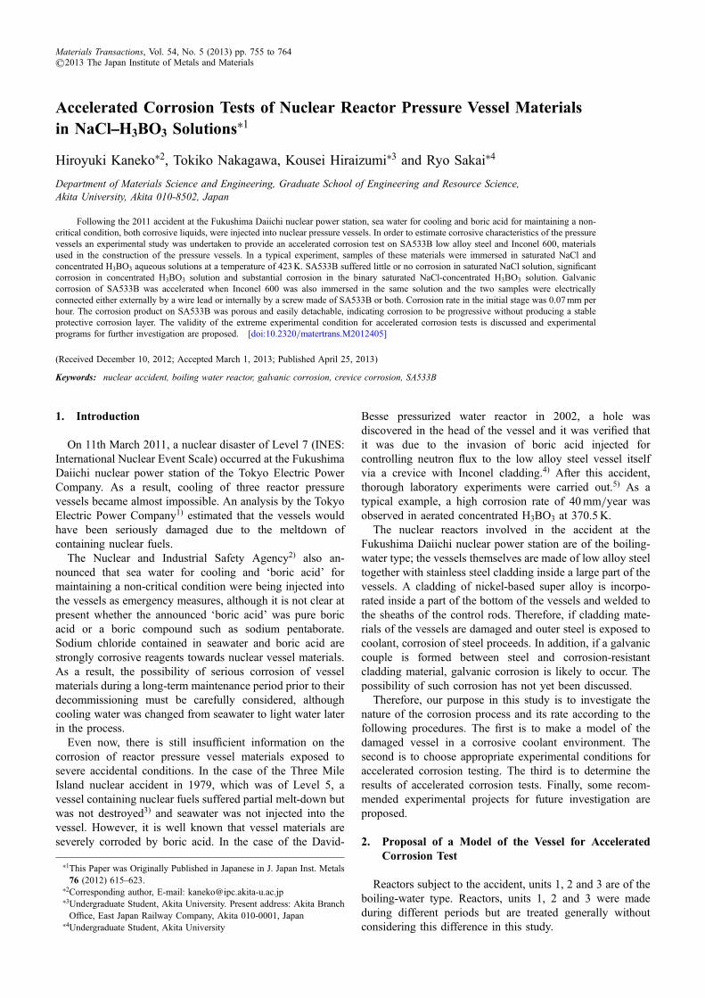
In Fig. 8, temperature dependence of corrosion current isshown. At 373K, a relatively large current flows. Therefore,even when the temperature is lowered from 423 to 373K,galvanic corrosion is decreased but it is not negligible. Froma reference,4) it is verified that corrosion in H3BO3 solutionis not changed much in the range 373 to 423K. At 298K,current density was a low value of 0.01A·m¹2.
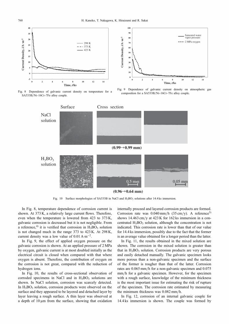
In Fig. 9, the effect of applied oxygen pressure on thegalvanic corrosion is shown. At an applied pressure of 2MPaby oxygen, galvanic current is at most doubled initially as theelectrical circuit is closed when compared with that whereoxygen is absent. Therefore, the contribution of oxygen onthe corrosion is not great, compared with the reduction ofhydrogen ions.
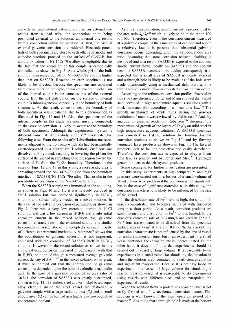
In Fig. 10, the results of cross-sectional observation ofcorroded specimens in NaCl and in H3BO3 solutions areshown. In NaCl solution, corrosion was scarcely detected.In H3BO3 solution, corrosion products were observed on thesurface and they appeared to be layered and detached layer bylayer leaving a rough surface. A thin layer was observed ata depth of 10 µm from the surface, showing that oxidation
internally proceed and layered corrosion products are formed.Corrosion rate was 0.040mm/h (35 cm/y). A reference5)
shows 14.463 cm/y at 423K for 162 ks immersion in a con-centrated H3BO3 solution, although the concentration is notindicated. This corrosion rate is lower than that of our valuefor 14.4 ks immersion, possibly due to the fact that the formeris an average value obtained for a longer period than the latter.
In Fig. 11, the results obtained in the mixed solution areshown. The corrosion in the mixed solution is greater thanthat in H3BO3 solution. Corrosion products are very porousand easily detached manually. The galvanic specimen looksmore porous than a non-galvanic specimen and the surfaceof the former is rougher than that of the latter. Corrosionrates are 0.065mm/h for a non-galvanic specimen and 0.075mm/h for a galvanic specimen. However, for the specimenwith a rough surface, knowledge of the minimum thicknessis the most important issue for estimating the risk of ruptureof the specimen. The corrosion rate estimated by measuringthe minimum thickness was 0.082mm/h.
In Fig. 12, corrosion of an internal galvanic couple for14.4 ks immersion is shown. The couple was formed by
0
10
20
30
40
50
60
70
80
90
100
0 2 4 6 8 10 12 14
Cur
rent
Den
sity
, i/A
· m-2
Time, t/ks
Saturated water vapor pressure
2 MPa oxygen
Fig. 9 Dependence of galvanic current density on atmospheric gascomposition for a SA533B/Ni16Cr7Fe alloy couple.
-5
0
5
10
15
20
25
30
35
40
0 2 4 6 8 10 12 14
Cur
rent
Den
sity
, i/A
· m-2
Time, t/ks
298 K
423 K373 K
Fig. 8 Dependence of galvanic current density on temperature for aSA533B/Ni16Cr7Fe alloy couple.
1 mm 0.5 mm
(0.96 0.64 mm)
NaClsolution
(0.99 0.99 mm)
0.05 mm
Surface Cross section
H3BO3
solution
Fig. 10 Surface morphologies of SA533B in NaCl and H3BO3 solutions after 14.4 ks immersion.
H. Kaneko, T. Nakagawa, K. Hiraizumi and R. Sakai760

connecting together a small piece of SA533B and a pieceof Ni16Cr7Fe of the same size; this was achieved bymachining a screw thread on the former and rotating this intoa corresponding threaded hole in the latter until tight.In appearance, SA533B was severely corroded and corrosionproducts on SA533B are easily detached. An enlargedphotograph shows that the interface is not smooth and Ni16Cr7Fe alloy appears to be corroded. The corrosion rateof SA533B determined by measuring the thickness of thecorrosion layer is 0.066mm/h.
In order to investigate the effect of the ratio of cathodicarea/anodic area, another internal galvanic couple with aratio of 36.5/1 was used; a hole was made in the center of adisc (5mm thick, 20mm diameter) of Ni16Cr7Fe alloy,into which a screw of SA533B of 4mm diameter wasinserted. Cross-sectional views of two specimens are shownin Fig. 13. Top parts of the SA533B screws were morecorroded than their bottom parts, indicating that at the topparts, evolved hydrogen is readily detached and the corrosionproceeds. On the other hand, at the bottom parts, evolved
hydrogen is trapped and the metal is isolated from directcontact with the solution thus hindering corrosion. Corrosionrates of top parts of two SA533B specimens were differentfrom each other; one was 0.26mm/h and the other was0.52mm/h. These values are very high, compared with thecorrosion rate of about 0.07mm/h for a cathodic area/anodic
SA533Bnot coupled
1 mm
SA533Bcoupled with Ni-16Cr-7Fe alloy
0.5 mm
(1.00 0.40 mm)
0.05 mm
Surface
(0.60 0.08 mm)
Cross section
Fig. 11 Surface morphologies of SA533B in NaClH3BO3 solution after 14.4 ks immersion.
SA533B
Ni-16Cr-7Fe alloy
1 mm5 mm1 mm
Surface Cross section
Fig. 12 Surface morphology of an internal galvanic couple. (Cathodic area/anodic area: 1/1)
Sample A Sample B
1 mm 1 mm
SA533BNi-16Cr-7Fe alloy Ni-16Cr-7Fe alloy
Fig. 13 Surface morphology of an internal galvanic couple. (Cathodicarea/anodic area: 36.5/1)
Accelerated Corrosion Tests of Nuclear Reactor Pressure Vessel Materials in NaClH3BO3 Solutions 761

area ratio of 1/1. In addition, it is well known that a nickel-based super alloy such as Inconel is corrosion-resistant ingeneral, but, crevice corrosion sometimes occurs.12) Thepossibility of crevice corrosion will be checked, if a long-term experiment is carried out.
In Table 3, comparison of the corrosion rates is shown.The results obtained from both of the polarization measure-ments and cross-sectional observation of the specimen are inagreement with each other. However, the result obtained bypolarization measurement is a rounded value, because theanalysis is dependent upon the calculation method, as shownpreviously. The values obtained by cross-sectional observa-tion are directly measured. But considering the experimentalerrors, accurate estimation of the effect of galvanic corrosionis not easy. As shown in Fig. 4, the measured average valueof 5A·m¹2, equivalent to 0.0006mm/h is difficult to bedetected from the cross-sectional observation of the speci-men. Nevertheless, in the initial stage of immersion, galvaniccurrent density of 40A·m¹2 or corrosion rate of 0.005mm/hwas detected, showing that the corrosion is accelerated atleast in the initial stage. Corrosion rate in NaClH3BO3 isabout 0.07mm/h (60 cm/y), both for non-galvanic andgalvanic specimens.
6. Discussion
The reaction mechanism is now discussed based uponthe experimental results. Iron is the major component ofSA533B; the other minor metallic components are morecorrosion-resistant than Fe. As a result, a principal anodicreaction is the oxidation of Fe to dissolved Fe2+ ions.
Fe ¼ Fe2þ þ 2e� ð1ÞBoric acid, H3BO3 is a weak acid and is partially dissolved
in H2O.13)
H3BO3 ð¼ BðOHÞ3Þ þ H2O ¼ BðOHÞ4� þ Hþ ð2ÞA cathodic reaction in an acidic solution is the reduction of
hydrogen ions to generate hydrogen gas.
2Hþ þ 2e� ¼ H2 ð3ÞThe net reaction resulting from the combination of
reactions (1) and (3) is the following.
Feþ 2Hþ ¼ Fe2þ þ H2 ð4ÞIt follows that corrosion of Fe in H3BO3 solution is
accompanied by hydrogen evolution. At the elevated tem-
perature of 423K, hydrogen overpotential may be lowerthan that at room temperature and reaction (4) is likely toproceed.
It was found that pH measured at 298K before and afterthe immersion experiment of 4 h duration in the NaClH3BO3
solution changed from 3.23 to 3.83, which indicates theconsumption of hydrogen ions during the corrosion process.In addition, hydrogen generation was verified by surveyingthe internal pressure of the experimental vessel: the pressurewas increased from the saturated water vapor pressure ofabout 0.5MPa at 423K to a total pressure of about 0.8MPawithin 1 h and then it remained at an steady value during theexperiment.
Hydrolysis of Fe2+ ions proceeds in the solution.18)
Fe2þ þ 4=3H2O ¼ 1=3Fe3O4 þ 2Hþ þ 1=3H2 ð5ÞHydrogen ions are generated according to reaction (5),
but consumed in reaction (4), so that corrosion of Fe isaccelerated. The solution after an immersion experimentlooks blue-colored. The surface of SA533B is black-coloredSo that in the solution surrounded by deaerated water vapor,corrosion does not reach the point corresponding to theformation of Fe2O3. Therefore, it is considered that thecorrosion product formed in the initial stage is Fe3O4.
At a high oxygen pressure or where dissolved oxygen isnot removed from solution by degassing, oxygen reductionproceeds as a cathodic reaction in acidic solution in additionto reaction (3).
1=2 O2 þ 2Hþ þ 2e� ¼ H2O ð6ÞThe effect of oxygen on the corrosion of Fe was verified,
as shown in Fig. 9.For the corrosion in NaClH3BO3 mixed solution, the
effect of added Cl¹ ions must be also considered as follows.
Fe2þ þ Cl� ¼ FeClþ ð7ÞAt a rough estimate, the ratio of [FeCl+]/[Fe2+] is 33 by
applying an association constant of 4.57 (mol/kg)¹1 at 423Kfor this reaction19) and a saturated chloride ion concentrationof 7.23mol/kg and by assuming that activity coefficients ofions are unity. As a result of the formation of soluble FeCl+
ions, the concentration of Fe2+ ions is lowered promotingthe dissolution of Fe2+ ions, so that the corrosion of Fe isalso accelerated. This may be the reason why SA533B wasscarcely corroded in neutral NaCl solution but its corrosionin H3BO3 solution was accelerated by adding NaCl.
In the FeBO system,20) many complex iron boratesare known. In the experiment in H3BO3 solution,4) FeB2O4
was identified as a corrosion product. For the formation ofFeB2O4, Fe2+ ions react with B(OH)4¹ ions, followed by adehydration step,
Fe2þ þ 2BðOHÞ4� ¼ FeB2O4 þ 4H2O ð8ÞFrom the experiment in H3BO3 in this study, the formation
of a corrosion product involving Fe, B and O was verifiedby EPMA, but a stoichiometric FeB2O4 is not identified.Corrosion products obtained in NaClH3BO3 solutioninvolved Fe, B, O and Cl.
Consider now the reaction mechanism for galvaniccorrosion via the SA533B/Ni16Cr7Fe alloy couple. There
Table 3 Calculated corrosion rates of SA533B at 423K.
NaCl H3BO3 NaClH3BO3
Not coupled Not coupled Not coupledCoupled with
Nickel based superalloy
Not detected0.040mm/h(35 cm/y)
0.065mm/h(57 cm/y)
0.075mm/h (External)(66 cm/y)
0.066mm/h (Internal)(58 cm/y)
0.07mm/h*(60 cm/y)
0.08mm/h*(70 cm/y)
*From the polarization analyses (see Fig. 3)
H. Kaneko, T. Nakagawa, K. Hiraizumi and R. Sakai762
are external and internal galvanic couples: an external oneresults from a lead wire, the connection point beingpositioned external to the solution; an internal one resultsfrom a connection within the solution. At first, the case ofexternal galvanic corrosion is considered. Electrode poten-tials of both specimens are close to each other and anodic andcathodic reactions proceed on the surface of SA533B, butanodic oxidation of Ni16Cr7Fe alloy is negligible due tothe fact that the corrosion of this couple is cathodicallycontrolled, as shown in Fig. 5. As a whole, pH of the bulksolution is increased but pH on Ni16Cr7Fe alloy is higherthan that on SA533B. Reaction on each specimen is notlikely to be affected, because the specimens are separatedfrom one another. In principle, corrosion reaction mechanismof the internal couple is the same as that of the externalcouple. But, the pH distribution on the surface of internalcouple is inhomogeneous, especially at the boundary of bothspecimens. As the result, corrosion near the boundary ofboth specimens was substantial due to this phenomenon asillustrated in Figs. 12 and 13. Also, the specimens of theinternal couple in this study are mechanically connected,so that crevice corrosion is likely to occur at the boundaryof both specimens. Although the experimental system isdifferent from that of this study, authors21) investigated thefollowing case. From the results of pH distribution measure-ments adjacent to the iron onto which Zn had been partiallyelectrodeposited in a neutral NaCl solution, Zn2+ ions aredissolved and hydrated, resulting in lowering the pH on thesurface of the Zn and in spreading an acidic region toward thesurface of Fe from the Fe/Zn boundary. Therefore, in thecases of Figs. 12 and 13 in this study, a more acidic area isspreading toward the Ni16Cr7Fe side from the boundaryinterface of SA533B/Ni16Cr7Fe alloy. That results in thepossibility of corrosion of the Ni16Cr7Fe alloy.
When the SA533B sample was immersed in the solutions,as shown in Figs. 10 and 11, it was scarcely corroded inNaCl solution but was corroded significantly in H3BO3
solution and substantially corroded in a mixed solution. Inthe case of the galvanic corrosion experiments, as shown inFig. 7, there was a very low corrosion current in NaClsolution, and was a low current in H3BO3 and a substantialcorrosion current in the mixed solution. So, galvaniccorrosion characteristic in the examined solutions is similarto corrosion characteristic of non-coupled specimen, in spiteof different experimental methods. A reference7) shows thatthe contribution of galvanic corrosion is not important,compared with the corrosion of SA533B itself in H3BO3
solution. However, in the mixed solution as shown in thisstudy, galvanic corrosion increased in comparison with thatin H3BO3 solution. Although a measured average galvaniccurrent density of 5A·m¹2 in the mixed solution is not great,it must be pointed out that the contribution of galvaniccorrosion is dependent upon the ratio of cathodic area/anodicarea. In the case of a galvanic couple of an area ratio of36.5/1, the corrosion of SA533B was greatly accelerated,shown in Fig. 13. If stainless steel and/or nickel based superalloy cladding inside the steel vessel are destroyed, agalvanic couple with a large cathodic area (Sc) and a smallanodic area (Sa) can be formed in a highly electro-conductiveconcentrated coolant.
As a first approximation, anodic current is proportional tothe area ratio Sc/Sa22) which is likely to be in the range 100to 1000. Therefore, even if the corrosion current measuredat a galvanic couple of the same areas of cathode and anodeis relatively low, it is possible that substantial galvaniccorrosion occurs depending upon the cathode/anode arearatio. Assuming that some corrosion resistant cladding isdestroyed and as a result, SA533B is exposed to the coolant,anodic current flows locally on SA533B and the coolantnear the SA533B becomes more acidic; consequently, it isexpected that a small area of SA533B is locally attackedand a through-hole is likely to be made, as if the hole weremade intentionally using a mechanical drill. Further, if athrough-hole is made, flow-accelerated corrosion can occur.
According to the references, corrosion profiles observed inthis study are discussed. Potter and Mann showed that a mildsteel corroded in high temperature aqueous solutions with athick laminated film according to a linear time law.23) Thegrowth mechanism of oxide films during the gaseousoxidation of metals was reviewed by Atkinson.24) And, byanalogy to gaseous oxidation, Robertson18) discussed themechanism of growth of the layers of Fe3O4 on mild steel inhigh temperature aqueous solutions. A SA533B specimenwas corroded in H3BO3 solution by forming layeredcorrosion products as shown in Fig. 10, and by forminglaminated layer products as shown in Fig. 11. The layeredproducts look to be non-protective and easily detachable.Therefore, the corrosion rate is expected to obey a lineartime law, as pointed out by Potter and Man.23) Hydrogengeneration acts to detach layered products.
Some comments for further investigation are presented.In this study, experiments at high temperature and high
pressure were carried out in a beaker of a small volume of70mL. There is no problem if the corrosion is not significant,but in the case of significant corrosion as in this study, thecorrosion characteristic is likely to be influenced by the sizeof the vessel.
If the dissolution rate of Fe2+ ions is high, the solution iseasily concentrated and becomes saturated with dissolvedions in a short period. As a result, corrosion products areeasily formed and dissolution of Fe2+ ions is limited. In thecase of a corrosion rate of 0.07mm/h analyzed in Table 3,Fe2+ ions are estimated to be dissolved from the specimensurface area of 4 cm2 at a rate of 0.4mol/h. As a result, thecorrosion characteristic is not influenced by the size of vesselfor a short immersion time, but if an experiment in a smallvessel continues, the corrosion rate is underestimated. On theother hand, it does not follow that experiments should becarried out in vessel of large volume. It is reasonable to doexperiments in a small vessel for simulating the situation inwhich the solution is concentrated by insufficient circulationand significant evaporation. Because it is not easy to do anexperiment in a vessel of large volume for simulating areactor pressure vessel, it is reasonable to do experimentsusing vessels with different sizes and to extrapolate theexperimental results.
When the solution flows, a protective corrosion layer is noteasily formed and flow-accelerated corrosion occurs. Thisproblem is well known in the usual operation period of areactor.25) Assuming that a through-hole is made at the bottom
Accelerated Corrosion Tests of Nuclear Reactor Pressure Vessel Materials in NaClH3BO3 Solutions 763

of the reactor pressure vessel, flow-accelerated corrosion willbe serious. If a pressure difference of 0.4MPa between theinside and outside of the reactor vessel and a coolant heightin the vessel of 5m are assumed, the flow rate calculatedby Torricelli’s formula (2 gh)0.5, approximates to the highvelocity of 30m/s. However, if the solution flows at highspeed, it is not easily concentrated; because the two effects arecontrary to each other it is not possible to predict which effectwill be dominant with regard to corrosion.
The solution system in which seawater and ‘boric acid’are injected, is generally expressed as the NaClH3BO3Na2B4O7 system. In this study, as an extremely acidiccondition, the NaClH3BO3 system was chosen. As a result,the corrosion of SA533B is significant, and as shown inFigs. 12 and 13, when SA533B and Ni16Cr7Fe alloy areconnected with each other and then if a crevice is formedbetween them, the boundary becomes acidic and corrosion isaccelerated. In further investigations, experiments should becarried out in NaClH3BO3Na2B4O7.
In this study, accelerated experiments were performed bymodeling an extremely serious situation for the corrosion ofthe reactor pressure vessel subjected to the accident atFukushima Daiichi nuclear plant. At present, cooling water ischanged from sea water to light water, and evaporation of thecoolant is substantially decreased by decreasing the temper-ature below 373K, and the concentration of the coolant ischanged very little. However, for at least two months reactorpressure vessels subjected to the accident were exposed in avery serious situation. Even if the situation is improved atpresent, hysteresis of vessel materials remains. As shown inthis study, corrosion products on SA533B are very porousand easily detached. Therefore, corrosion products involveNaCl and H3BO3, and a stable protective corrosion layer isnot easily formed, even if the situation is improved. For thecorrosion study on reactor vessels subject to the accident, it isnecessary to do experiments taking into consideration thepossible hysteresis of vessels.
7. Conclusions
In emergency, corrosive seawater and ‘boric acid’ wereinjected into the reactor vessels of Fukushima Daiichi nuclearpower station. In general, the solution system is considered toapproximate to NaClH3BO3Na2B4O7 system. Experimentalconditions for accelerated corrosion tests were consideredfor SA533B and Ni16Cr7Fe alloy (Inconel 600) as vesselmaterials. Experiments for non-galvanic SA533B andgalvanic couple with Ni16Cr7Fe alloy were carried outespecially in a saturated NaCl-concentrated H3BO3 solution.
The results are:(1) SA533B is scarcely corroded in NaCl solution,
significantly corroded in H3BO3 solution and substan-tially corroded in NaClH3BO3 solution.
(2) The corrosion of SA533B is accelerated by forming agalvanic couple with Ni16Cr7Fe alloy.
(3) The corrosion rate in the initial stage is 0.07mm/h, onthe assumption that the corrosion rate is constant withtime, this is equivalent to 60 cm/y.
(4) Corrosion products are porous and easily detached andas a result a protective corrosion layer is not formed.
As the next step, the possibility of significant corrosionshould be checked in a wide range of experimentalconditions. Some comments for further investigation arepresented.
Acknowledgements
This study was supported by Grant-in-Aid for ChallengingExploratory Research (24656433) of the Ministry ofEducation, Culture, Sports, Science and Technology. Wethank Emeritus Professor Masayuki Hasegawa of TohokuUniversity for his useful comments.
REFERENCES
1) The evaluation status of reactor core damage at Fukushima Daiichinuclear power station units 1 to 3, (Tokyo Electric Power Company,Nov. 30, 2011): http://www.tepco.co.jp/nu/fukushima-np/images/handouts_111130_07-j.pdf.
2) Seismic damage information in the period Mar. 11Jul. 31, (Nuclearand Industrial Safety Agency, Sep. 1, 2011): http://www.meti.go.jp/press/2011/09/20110901006/20110901006-6.pdf.
3) B. Ray Sejgal (ed.): Nuclear Safety in Light Water Reactors, (AcademicPress, 2012) pp. 2733.
4) NRC information notice 2002-11, (US Nuclear Regulatory Com-mission, Washington, 2002): http://www.nrc.gov/reading-rm/doc-collections/gen-comm/info-notices/2002/in02011.html.
5) NUREG/CR-6875, (US Nuclear Regulatory Commission, Washington,2005) pp. 148.
6) Interim report of the Investigation Committee on the accident at theFukushima nuclear power stations of Tokyo Electric Power Company,(Dec. 26, 2011) p. II-13.
7) T. Toyama, Y. Nagai, Z. Tang, M. Hasegawa, A. Almazouzi, E. vanWalle and R. Gerad: Acta Mater. 55 (2007) 68526860.
8) Technical assessment of aging: On unit 1 at the Fukushima nuclearpower stations of Tokyo Electric Power Company, (Japan NuclearEnergy Safety Organization, Feb. 3, 2011): http://plec.jnes.go.jp/vlr_index.html.
9) T. Kodaira: Tetsu-to-Hagane 73 (1987) 16561667.10) T. Takeuchi, A. Kuramoto, J. Kameda, T. Toyama, Y. Nagai, M.
Hasegawa, T. Ohkubo, T. Yoshiie, Y. Nishiyama and K. Onizawa:J. Nucl. Mater. 402 (2010) 93101.
11) NUREG/CR-6988, (US Nuclear Regulatory Commission, Washington,2009) pp. 3335.
12) NUREG-1823, (US Nuclear Regulatory Commission, Washington,2005) pp. 319.
13) K. Othmer: Encyclopedia of Chemical Technology, (John Wiley andSons, Inc., New York, 1978) Vol. 4, p. 85.
14) W. F. Linke: Solubilities of Inorganic and MetalOrganic Compounds,(Van Nostrand, New York, 1958) Vol. II, p. 959.
15) W. F. Linke: Solubilities of Inorganic and MetalOrganic Compounds,(Van Nostrand, New York, 1958) Vol. I, p. 262.
16) G. Di Giacomo, P. Brandani, V. Brandani and G. Del Re: Desalination91 (1993) 2133.
17) T. Nakagawa: J. Japan Inst. Metals 68 (2004) 1420.18) J. Robertson: Corros. Sci. 29 (1989) 12751291.19) C. A. Heinrich and T. M. Seward: Geochim. Cosmochim. Acta 54
(1990) 22072221.20) J. S. Knyrim and H. Huppertz: J. Solid State Chem. 181 (2008) 2092
2098.21) E. Tada, K. Sugawara and H. Kaneko: Electrochim. Acta 49 (2004)
10191026.22) F. Mansfeld: Corrosion 27 (1971) 436442.23) E. C. Potter and G. M. W. Mann: Br. Corros. J. 1 (1965) 2635.24) A. Atkinson: Rev. Modern Phys. 57 (1985) 437470.25) NRC information notice 97-84, (US Nuclear Regulatory Commission,
Washington, 1997): http://www.nrc.gov/reading-rm/doc-collections/gen-comm/info-notices/1997/in97084.html.
H. Kaneko, T. Nakagawa, K. Hiraizumi and R. Sakai764