Embed Size (px)
Citation preview

Accela Open Autosampler
Hardware Manual60357-97102 Revision B March 2011

© 2011 Thermo Fisher Scientific Inc. All rights reserved.
Xcalibur is a registered trademark of Thermo Fisher Scientific Inc. in the United States.
The following are registered trademarks in the United States and other countries: Microsoft and Windows are registered trademarks of Microsoft Corporation. Teflon and Kalrez are registered trademarks of E.I. du Pont de Nemours & Company. Unimetrics is a registered trademark of Unimetrics Company. Tygon is a registered trade mark of Saint-Gobain Performance Plastics Company. Rheodyne and the Rheodyne logo are registered trademarks of Rheodyne, L.P. PAL is a trademark of CTC Analytics AG. Agilent is a registered trademark of Agilent Technologies Inc. Ryton is a registered trademark of Chevron Phillips Chemical Company. Valco, VICI, and Cheminert are registered trademarks of Valco Instruments Company, Inc. Simriz is a registered trademark of Carl Freudenberg KG Corporation. Torx is a registered trademark of Textron Inc.
PEEK is a trademark of Victrex plc.
All other trademarks are the property of Thermo Fisher Scientific and its subsidiaries.
Thermo Fisher Scientific Inc. provides this document to its customers with a product purchase to use in the product operation. This document is copyright protected and any reproduction of the whole or any part of this document is strictly prohibited, except with the written authorization of Thermo Fisher Scientific Inc.
The contents of this document are subject to change without notice. All technical information in this document is for reference purposes only. System configurations and specifications in this document supersede all previous information received by the purchaser.
Thermo Fisher Scientific Inc. makes no representations that this document is complete, accurate or error-free and assumes no responsibility and will not be liable for any errors, omissions, damage or loss that might result from any use of this document, even if the information in the document is followed properly.
This document is not part of any sales contract between Thermo Fisher Scientific Inc. and a purchaser. This document shall in no way govern or modify any Terms and Conditions of Sale, which Terms and Conditions of Sale shall govern all conflicting information between the two documents.
Release history: Revision A, April, 2010; Revision B, March 2011.
Software versions: LC Devices 2.5.0 or later; ChromQuest 5.0 or later.
For Research Use Only. Not for use in diagnostic procedures.
Regulatory Compliance
Thermo Fisher Scientific performs complete testing and evaluation of its products to ensure full compliance with applicable domestic and international regulations. When the system is delivered to you, it meets all pertinent electromagnetic compatibility (EMC) and safety standards.
Changes that you make to your system may void compliance with one or more of these EMC and safety standards. Changes to your system include replacing a part or adding components, options, or peripherals not specifically authorized and qualified by Thermo Fisher Scientific. To ensure continued compliance with EMC and safety standards, replacement parts and additional components, options, and peripherals must be ordered from Thermo Fisher Scientific or one of its authorized representatives.
Accela Open Autosampler
EMC Directive 2004/108/EC
EMC compliance has been evaluated by CTC Analytics for the HTC PAL™ autosampler.
Low Voltage Safety Compliance
Low Voltage Safety Compliance has been evaluated by CTC Analystics for the HTC PAL autosampler.
This device complies with Low Voltage Directive 2006/95/EC and harmonized standard EN 61010-1:2001, IEC 61010-1:2001, ANSI/UL 61010 A-1:2004, CAN/CSA 22.2 61010-1:2004.
FCC Compliance Statement
IEC 61326-1:2005 IEC 61326-2-6:2005
EN 61326-1:1997, A1:1998 CISPR 22:2005, A1:2005, A2:2006
FCC Class A, CFR 47 Part 15:2003
THIS DEVICE COMPLIES WITH PART 15 OF THE FCC RULES. OPERATION IS SUBJECT TO THE FOLLOWING TWO CONDITIONS: (1) THIS DEVICE MAY NOT CAUSE HARMFUL INTERFERENCE, AND (2) THIS DEVICE MUST ACCEPT ANY INTERFERENCE RECEIVED, INCLUDING INTERFERENCE THAT MAY CAUSE UNDESIRED OPERATION.

Notice on Lifting and Handling ofThermo Scientific Instruments
For your safety, and in compliance with international regulations, the physical handling of this Thermo Fisher Scientific instrument requires a team effort to lift and/or move the instrument. This instrument is too heavy and/or bulky for one person alone to handle safely.
Notice on the Proper Use ofThermo Scientific Instruments
In compliance with international regulations: Use of this instrument in a manner not specified by Thermo Fisher Scientific could impair any protection provided by the instrument.
Notice on the Susceptibility to Electromagnetic Transmissions
Your instrument is designed to work in a controlled electromagnetic environment. Do not use radio frequency transmitters, such as mobile phones, in close proximity to the instrument.
For manufacturing location, see the label on the instrument.
CAUTION Read and understand the various precautionary notes, signs, and symbols contained inside this manual pertaining to the safe use and operation of this product before using the device.
WEEE Compliance
This product is required to comply with the European Union’s Waste Electrical & Electronic Equipment (WEEE) Directive 2002/96/EC. It is marked with the following symbol:
Thermo Fisher Scientific has contracted with one or more recycling or disposal companies in each European Union (EU) Member State, and these companies should dispose of or recycle this product. See www.thermo.com/WEEERoHS for further information on Thermo Fisher Scientific’s compliance with these Directives and the recyclers in your country.
WEEE Konformität
Dieses Produkt muss die EU Waste Electrical & Electronic Equipment (WEEE) Richtlinie 2002/96/EC erfüllen. Das Produkt ist durch folgendes Symbol gekennzeichnet:
Thermo Fisher Scientific hat Vereinbarungen mit Verwertungs-/Entsorgungsfirmen in allen EU-Mitgliedsstaaten getroffen, damit dieses Produkt durch diese Firmen wiederverwertet oder entsorgt werden kann. Mehr Information über die Einhaltung dieser Anweisungen durch Thermo Fisher Scientific, über die Verwerter, und weitere Hinweise, die nützlich sind, um die Produkte zu identifizieren, die unter diese RoHS Anweisung fallen, finden sie unter www.thermo.com/WEEERoHS.

Conformité DEEE
Ce produit doit être conforme à la directive européenne (2002/96/EC) des Déchets d'Equipements Electriques et Electroniques (DEEE). Il est marqué par le symbole suivant:
Thermo Fisher Scientific s'est associé avec une ou plusieurs compagnies de recyclage dans chaque état membre de l’union européenne et ce produit devrait être collecté ou recyclé par celles-ci. Davantage d'informations sur la conformité de Thermo Fisher Scientific à ces directives, les recycleurs dans votre pays et les informations sur les produits Thermo Fisher Scientific qui peuvent aider la détection des substances sujettes à la directive RoHS sont disponibles sur www.thermo.com/WEEERoHS.
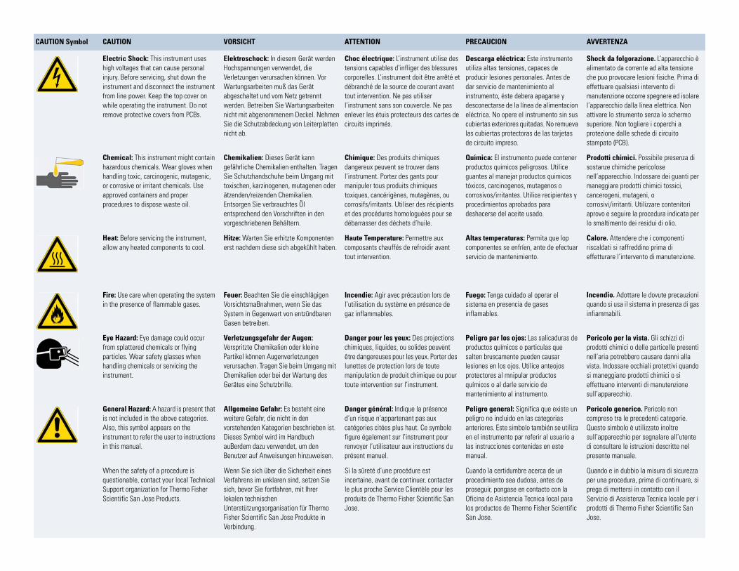
CAUTION Symbol CAUTION VORSICHT ATTENTION PRECAUCION AVVERTENZA
Electric Shock: This instrument uses high voltages that can cause personal injury. Before servicing, shut down the instrument and disconnect the instrument from line power. Keep the top cover on while operating the instrument. Do not remove protective covers from PCBs.
Elektroschock: In diesem Gerät werden Hochspannungen verwendet, die Verletzungen verursachen können. Vor Wartungsarbeiten muß das Gerät abgeschaltet und vom Netz getrennt werden. Betreiben Sie Wartungsarbeiten nicht mit abgenommenem Deckel. Nehmen Sie die Schutzabdeckung von Leiterplatten nicht ab.
Choc électrique: L’instrument utilise des tensions capables d’infliger des blessures corporelles. L’instrument doit être arrêté et débranché de la source de courant avant tout intervention. Ne pas utiliser l’instrument sans son couvercle. Ne pas enlever les étuis protecteurs des cartes de circuits imprimés.
Descarga eléctrica: Este instrumento utiliza altas tensiones, capaces de producir lesiones personales. Antes de dar servicio de mantenimiento al instrumento, éste debera apagarse y desconectarse de la línea de alimentacion eléctrica. No opere el instrumento sin sus cubiertas exteriores quitadas. No remueva las cubiertas protectoras de las tarjetas de circuito impreso.
Shock da folgorazione. L’apparecchio è alimentato da corrente ad alta tensione che puo provocare lesioni fisiche. Prima di effettuare qualsiasi intervento di manutenzione occorre spegnere ed isolare l’apparecchio dalla linea elettrica. Non attivare lo strumento senza lo schermo superiore. Non togliere i coperchi a protezione dalle schede di circuito stampato (PCB).
Chemical: This instrument might contain hazardous chemicals. Wear gloves when handling toxic, carcinogenic, mutagenic, or corrosive or irritant chemicals. Use approved containers and proper procedures to dispose waste oil.
Chemikalien: Dieses Gerät kann gefährliche Chemikalien enthalten. Tragen Sie Schutzhandschuhe beim Umgang mit toxischen, karzinogenen, mutagenen oder ätzenden/reizenden Chemikalien. Entsorgen Sie verbrauchtes Öl entsprechend den Vorschriften in den vorgeschriebenen Behältern.
Chimique: Des produits chimiques dangereux peuvent se trouver dans l’instrument. Portez des gants pour manipuler tous produits chimiques toxiques, cancérigènes, mutagènes, ou corrosifs/irritants. Utiliser des récipients et des procédures homologuées pour se débarrasser des déchets d’huile.
Química: El instrumento puede contener productos quimicos peligrosos. Utilice guantes al manejar productos quimicos tóxicos, carcinogenos, mutagenos o corrosivos/irritantes. Utilice recipientes y procedimientos aprobados para deshacerse del aceite usado.
Prodotti chimici. Possibile presenza di sostanze chimiche pericolose nell’apparecchio. Indossare dei guanti per maneggiare prodotti chimici tossici, cancerogeni, mutageni, o corrosivi/irritanti. Utilizzare contenitori aprovo e seguire la procedura indicata per lo smaltimento dei residui di olio.
Heat: Before servicing the instrument, allow any heated components to cool.
Hitze: Warten Sie erhitzte Komponenten erst nachdem diese sich abgekühlt haben.
Haute Temperature: Permettre aux composants chauffés de refroidir avant tout intervention.
Altas temperaturas: Permita que lop componentes se enfríen, ante de efectuar servicio de mantenimiento.
Calore. Attendere che i componenti riscaldati si raffreddino prima di effetturare l’intervento di manutenzione.
Fire: Use care when operating the system in the presence of flammable gases.
Feuer: Beachten Sie die einschlägigen VorsichtsmaBnahmen, wenn Sie das System in Gegenwart von entzündbaren Gasen betreiben.
Incendie: Agir avec précaution lors de l’utilisation du système en présence de gaz inflammables.
Fuego: Tenga cuidado al operar el sistema en presencia de gases inflamables.
Incendio. Adottare le dovute precauzioni quando si usa il sistema in presenza di gas infiammabili.
Eye Hazard: Eye damage could occur from splattered chemicals or flying particles. Wear safety glasses when handling chemicals or servicing the instrument.
Verletzungsgefahr der Augen: Verspritzte Chemikalien oder kleine Partikel können Augenverletzungen verursachen. Tragen Sie beim Umgang mit Chemikalien oder bei der Wartung des Gerätes eine Schutzbrille.
Danger pour les yeux: Des projections chimiques, liquides, ou solides peuvent être dangereuses pour les yeux. Porter des lunettes de protection lors de toute manipulation de produit chimique ou pour toute intervention sur l’instrument.
Peligro par los ojos: Las salicaduras de productos químicos o particulas que salten bruscamente pueden causar lesiones en los ojos. Utilice anteojos protectores al mnipular productos químicos o al darle servicio de mantenimiento al instrumento.
Pericolo per la vista. Gli schizzi di prodotti chimici o delle particelle presenti nell’aria potrebbero causare danni alla vista. Indossare occhiali protettivi quando si maneggiano prodotti chimici o si effettuano interventi di manutenzione sull’apparecchio.
General Hazard: A hazard is present that is not included in the above categories. Also, this symbol appears on the instrument to refer the user to instructions in this manual.
Allgemeine Gefahr: Es besteht eine weitere Gefahr, die nicht in den vorstehenden Kategorien beschrieben ist. Dieses Symbol wird im Handbuch auBerdem dazu verwendet, um den Benutzer auf Anweisungen hinzuweisen.
Danger général: Indique la présence d’un risque n’appartenant pas aux catégories citées plus haut. Ce symbole figure également sur l’instrument pour renvoyer l’utilisateur aux instructions du présent manuel.
Peligro general: Significa que existe un peligro no incluido en las categorias anteriores. Este simbolo también se utiliza en el instrumento par referir al usuario a las instrucciones contenidas en este manual.
Pericolo generico. Pericolo non compreso tra le precedenti categorie. Questo simbolo è utilizzato inoltre sull’apparecchio per segnalare all’utente di consultare le istruzioni descritte nel presente manuale.
When the safety of a procedure is questionable, contact your local Technical Support organization for Thermo Fisher Scientific San Jose Products.
Wenn Sie sich über die Sicherheit eines Verfahrens im unklaren sind, setzen Sie sich, bevor Sie fortfahren, mit Ihrer lokalen technischen Unterstützungsorganisation für Thermo Fisher Scientific San Jose Produkte in Verbindung.
Si la sûreté d’une procédure est incertaine, avant de continuer, contacter le plus proche Service Clientèle pour les produits de Thermo Fisher Scientific San Jose.
Cuando la certidumbre acerca de un procedimiento sea dudosa, antes de proseguir, pongase en contacto con la Oficina de Asistencia Tecnica local para los productos de Thermo Fisher Scientific San Jose.
Quando e in dubbio la misura di sicurezza per una procedura, prima di continuare, si prega di mettersi in contatto con il Servizio di Assistenza Tecnica locale per i prodotti di Thermo Fisher Scientific San Jose.
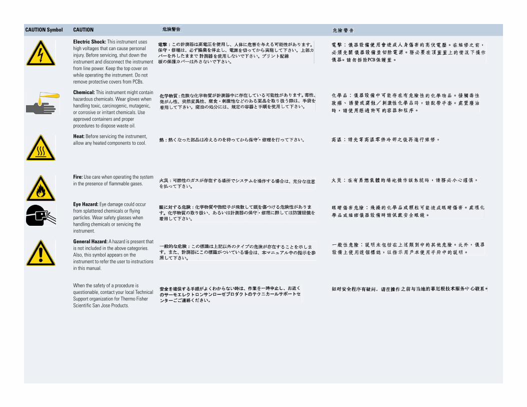
CAUTION Symbol CAUTION
Electric Shock: This instrument uses high voltages that can cause personal injury. Before servicing, shut down the instrument and disconnect the instrument from line power. Keep the top cover on while operating the instrument. Do not remove protective covers from PCBs.
Chemical: This instrument might contain hazardous chemicals. Wear gloves when handling toxic, carcinogenic, mutagenic, or corrosive or irritant chemicals. Use approved containers and proper procedures to dispose waste oil.
Heat: Before servicing the instrument, allow any heated components to cool.
Fire: Use care when operating the system in the presence of flammable gases.
Eye Hazard: Eye damage could occur from splattered chemicals or flying particles. Wear safety glasses when handling chemicals or servicing the instrument.
General Hazard: A hazard is present that is not included in the above categories. Also, this symbol appears on the instrument to refer the user to instructions in this manual.
When the safety of a procedure is questionable, contact your local Technical Support organization for Thermo Fisher Scientific San Jose Products.
Thermo Scientific Accela Open Autosampler Hardware Manual ix
C
Preface . . . . . . . . . . . . . . . . . . . . . . . . . . . . . . . . . . . . . . . . . . . . . . . . . . . . . . . . . . . . . .xvRelated Documentation . . . . . . . . . . . . . . . . . . . . . . . . . . . . . . . . . . . . . . . . . . xvSafety and Special Notices . . . . . . . . . . . . . . . . . . . . . . . . . . . . . . . . . . . . . . . . xvContacting Us . . . . . . . . . . . . . . . . . . . . . . . . . . . . . . . . . . . . . . . . . . . . . . . . .xvi
Chapter 1 Introduction . . . . . . . . . . . . . . . . . . . . . . . . . . . . . . . . . . . . . . . . . . . . . . . . . . . . . . . . . . .1Open Autosampler Components . . . . . . . . . . . . . . . . . . . . . . . . . . . . . . . . . . . . . 1
Main Components . . . . . . . . . . . . . . . . . . . . . . . . . . . . . . . . . . . . . . . . . . . . . 1Dynamic Load and Wash (DLW) . . . . . . . . . . . . . . . . . . . . . . . . . . . . . . . . . . 3
Specifications. . . . . . . . . . . . . . . . . . . . . . . . . . . . . . . . . . . . . . . . . . . . . . . . . . . . 6Physical Specifications . . . . . . . . . . . . . . . . . . . . . . . . . . . . . . . . . . . . . . . . . . . . . 8Operating and Environmental Requirements . . . . . . . . . . . . . . . . . . . . . . . . . . . 9Sound Pressure Level . . . . . . . . . . . . . . . . . . . . . . . . . . . . . . . . . . . . . . . . . . . . . 9
Chapter 2 Installing the Accela Open Autosampler . . . . . . . . . . . . . . . . . . . . . . . . . . . . . . . . .11Installing the Autosampler and DLW . . . . . . . . . . . . . . . . . . . . . . . . . . . . . . . . 11
Unpacking the Components . . . . . . . . . . . . . . . . . . . . . . . . . . . . . . . . . . . . . 11Assembling the Open Autosampler . . . . . . . . . . . . . . . . . . . . . . . . . . . . . . . . 14Installing the DLW . . . . . . . . . . . . . . . . . . . . . . . . . . . . . . . . . . . . . . . . . . . . 26Electrical Connections. . . . . . . . . . . . . . . . . . . . . . . . . . . . . . . . . . . . . . . . . . 35
System Synchronization Connections . . . . . . . . . . . . . . . . . . . . . . . . . . . . . . . . 38Connecting the Accela Open Autosampler Interconnect Cable . . . . . . . . . . . 39Connecting the Adapter Cable for an Accela Detector or TSQ Series
MS Detector . . . . . . . . . . . . . . . . . . . . . . . . . . . . . . . . . . . . . . . . . . . . . . . 42Connecting the Accela Pump Adapter Cable . . . . . . . . . . . . . . . . . . . . . . . . . 46
Connecting the Accela Open Autosampler to the Data System Computer. . . . . 49Accela Open Autosampler Object Positions. . . . . . . . . . . . . . . . . . . . . . . . . . . . 49
Defining Object Positions . . . . . . . . . . . . . . . . . . . . . . . . . . . . . . . . . . . . . . . 49Description of Object Positions. . . . . . . . . . . . . . . . . . . . . . . . . . . . . . . . . . . 51
Injection Valve . . . . . . . . . . . . . . . . . . . . . . . . . . . . . . . . . . . . . . . . . . . . . . . . . 60Valve Drives and Valves – General Remarks . . . . . . . . . . . . . . . . . . . . . . . . . 60Injection Valve Flow Path . . . . . . . . . . . . . . . . . . . . . . . . . . . . . . . . . . . . . . . 60
Contents
Contents
x Accela Open Autosampler Hardware Manual Thermo Scientific
Chapter 3 Operating the Accela Open Autosampler. . . . . . . . . . . . . . . . . . . . . . . . . . . . . . . . .65Control Terminal . . . . . . . . . . . . . . . . . . . . . . . . . . . . . . . . . . . . . . . . . . . . . . . 65
Menu Screens . . . . . . . . . . . . . . . . . . . . . . . . . . . . . . . . . . . . . . . . . . . . . . . . 66Function Keys . . . . . . . . . . . . . . . . . . . . . . . . . . . . . . . . . . . . . . . . . . . . . . . . 67ESC and STOP Keys. . . . . . . . . . . . . . . . . . . . . . . . . . . . . . . . . . . . . . . . . . . 67Scroll Knob and Enter Button . . . . . . . . . . . . . . . . . . . . . . . . . . . . . . . . . . . . 67
Methods . . . . . . . . . . . . . . . . . . . . . . . . . . . . . . . . . . . . . . . . . . . . . . . . . . . . . . 67Creating Methods . . . . . . . . . . . . . . . . . . . . . . . . . . . . . . . . . . . . . . . . . . . . . 67Editing and Viewing Methods . . . . . . . . . . . . . . . . . . . . . . . . . . . . . . . . . . . . 68Deleting Methods . . . . . . . . . . . . . . . . . . . . . . . . . . . . . . . . . . . . . . . . . . . . . 69
Job and Job Queue . . . . . . . . . . . . . . . . . . . . . . . . . . . . . . . . . . . . . . . . . . . . . . 69Building and Starting a Job Queue . . . . . . . . . . . . . . . . . . . . . . . . . . . . . . . . 70Cancelling a Job Queue. . . . . . . . . . . . . . . . . . . . . . . . . . . . . . . . . . . . . . . . . 71Restarting a Cancelled Job Queue . . . . . . . . . . . . . . . . . . . . . . . . . . . . . . . . . 71
Utility Functions . . . . . . . . . . . . . . . . . . . . . . . . . . . . . . . . . . . . . . . . . . . . . . . . 71Syringe . . . . . . . . . . . . . . . . . . . . . . . . . . . . . . . . . . . . . . . . . . . . . . . . . . . . . 72Tray. . . . . . . . . . . . . . . . . . . . . . . . . . . . . . . . . . . . . . . . . . . . . . . . . . . . . . . . 73Injector . . . . . . . . . . . . . . . . . . . . . . . . . . . . . . . . . . . . . . . . . . . . . . . . . . . . . 74Wash Station . . . . . . . . . . . . . . . . . . . . . . . . . . . . . . . . . . . . . . . . . . . . . . . . . 75Vial . . . . . . . . . . . . . . . . . . . . . . . . . . . . . . . . . . . . . . . . . . . . . . . . . . . . . . . . 76Dilutors . . . . . . . . . . . . . . . . . . . . . . . . . . . . . . . . . . . . . . . . . . . . . . . . . . . . . 76Tools . . . . . . . . . . . . . . . . . . . . . . . . . . . . . . . . . . . . . . . . . . . . . . . . . . . . . . . 77
Logfile . . . . . . . . . . . . . . . . . . . . . . . . . . . . . . . . . . . . . . . . . . . . . . . . . . . . . . . . 78Info Functions. . . . . . . . . . . . . . . . . . . . . . . . . . . . . . . . . . . . . . . . . . . . . . . . . . 78
Hardware . . . . . . . . . . . . . . . . . . . . . . . . . . . . . . . . . . . . . . . . . . . . . . . . . . . 79Software . . . . . . . . . . . . . . . . . . . . . . . . . . . . . . . . . . . . . . . . . . . . . . . . . . . . 79Maintenance . . . . . . . . . . . . . . . . . . . . . . . . . . . . . . . . . . . . . . . . . . . . . . . . . 79Free Objects/Free Items. . . . . . . . . . . . . . . . . . . . . . . . . . . . . . . . . . . . . . . . . 80
Setup Functions . . . . . . . . . . . . . . . . . . . . . . . . . . . . . . . . . . . . . . . . . . . . . . . . 80Sound . . . . . . . . . . . . . . . . . . . . . . . . . . . . . . . . . . . . . . . . . . . . . . . . . . . . . . 81Time . . . . . . . . . . . . . . . . . . . . . . . . . . . . . . . . . . . . . . . . . . . . . . . . . . . . . . . 81Objects . . . . . . . . . . . . . . . . . . . . . . . . . . . . . . . . . . . . . . . . . . . . . . . . . . . . . 82
Communicating with the Computer . . . . . . . . . . . . . . . . . . . . . . . . . . . . . . . . . 82
Chapter 4 Installing Cycle Composer Macros or ICC Cycles Used for the DLW Option85Installing the Thermo PAL Driver Macros or ICC Cycles . . . . . . . . . . . . . . . . . 86General Considerations . . . . . . . . . . . . . . . . . . . . . . . . . . . . . . . . . . . . . . . . . . . 86Priming the Solvent Lines, Wash1 and Wash2 . . . . . . . . . . . . . . . . . . . . . . . . . 87Standard DLW Injection Cycle . . . . . . . . . . . . . . . . . . . . . . . . . . . . . . . . . . . . . 88Fast DLW Injection Cycle. . . . . . . . . . . . . . . . . . . . . . . . . . . . . . . . . . . . . . . . . 91
Chapter 5 Operating Dynamic Load and Wash (DLW) . . . . . . . . . . . . . . . . . . . . . . . . . . . . . . .93Priming the Solvent Lines . . . . . . . . . . . . . . . . . . . . . . . . . . . . . . . . . . . . . . . . . 93Location of Solvent and Waste Bottles . . . . . . . . . . . . . . . . . . . . . . . . . . . . . . . 93
Contents
Thermo Scientific Accela Open Autosampler Hardware Manual xi
Functionality of the DLW Option . . . . . . . . . . . . . . . . . . . . . . . . . . . . . . . . . . 94DLW Pumps . . . . . . . . . . . . . . . . . . . . . . . . . . . . . . . . . . . . . . . . . . . . . . . . . 94DLW Actuator/Solenoid . . . . . . . . . . . . . . . . . . . . . . . . . . . . . . . . . . . . . . . . 94
DLW Cycle Step-By-Step . . . . . . . . . . . . . . . . . . . . . . . . . . . . . . . . . . . . . . . . . 96Cycle for Standard Injection . . . . . . . . . . . . . . . . . . . . . . . . . . . . . . . . . . . . . 96Additional Valve Toggle Step to DLW Standard Cycle . . . . . . . . . . . . . . . . 109Cycle for Fast Injection . . . . . . . . . . . . . . . . . . . . . . . . . . . . . . . . . . . . . . . . 118
Chapter 6 Operating the Temperature Controllable Stack Coolers . . . . . . . . . . . . . . . . . . .131Temperature Setting, Control, and Alarm . . . . . . . . . . . . . . . . . . . . . . . . . . . . 131
Temperature Setting . . . . . . . . . . . . . . . . . . . . . . . . . . . . . . . . . . . . . . . . . . 131Temperature Control . . . . . . . . . . . . . . . . . . . . . . . . . . . . . . . . . . . . . . . . . 132Temperature Alarm . . . . . . . . . . . . . . . . . . . . . . . . . . . . . . . . . . . . . . . . . . . 133
Temperature Stability . . . . . . . . . . . . . . . . . . . . . . . . . . . . . . . . . . . . . . . . . . . 133Condensation Build-Up . . . . . . . . . . . . . . . . . . . . . . . . . . . . . . . . . . . . . . . . . 134
Condensation Build-Up in Accela Open Autosampler Stack Coolers. . . . . . 134Condensation Build-Up in PAL Tray Coolers . . . . . . . . . . . . . . . . . . . . . . . 135
Chapter 7 Troubleshooting. . . . . . . . . . . . . . . . . . . . . . . . . . . . . . . . . . . . . . . . . . . . . . . . . . . . . .137Troubleshooting Using Observed Symptoms or Error Messages . . . . . . . . . . . 137Cooled Stack Power Supply Error Messages . . . . . . . . . . . . . . . . . . . . . . . . . . 141Troubleshooting Considerations . . . . . . . . . . . . . . . . . . . . . . . . . . . . . . . . . . . 142
Tubing Connections . . . . . . . . . . . . . . . . . . . . . . . . . . . . . . . . . . . . . . . . . . 142Solvent Delivery Pumps Not Priming . . . . . . . . . . . . . . . . . . . . . . . . . . . . . 147Solvent Delivery Pump Not Functioning . . . . . . . . . . . . . . . . . . . . . . . . . . 147
Standard Chromatographic Tests . . . . . . . . . . . . . . . . . . . . . . . . . . . . . . . . . . 148Carryover Test with UV-Detection . . . . . . . . . . . . . . . . . . . . . . . . . . . . . . . 149Repeatability Test with UV-Detection. . . . . . . . . . . . . . . . . . . . . . . . . . . . . 150
Chapter 8 Replacement Parts . . . . . . . . . . . . . . . . . . . . . . . . . . . . . . . . . . . . . . . . . . . . . . . . . . .153DLW Pump Module . . . . . . . . . . . . . . . . . . . . . . . . . . . . . . . . . . . . . . . . . . . . 154DLW Wash Station. . . . . . . . . . . . . . . . . . . . . . . . . . . . . . . . . . . . . . . . . . . . . 154DLW Syringe . . . . . . . . . . . . . . . . . . . . . . . . . . . . . . . . . . . . . . . . . . . . . . . . . 154DLW Syringe Holder Assembly . . . . . . . . . . . . . . . . . . . . . . . . . . . . . . . . . . . 154DLW Option Spare Parts Ordering Information. . . . . . . . . . . . . . . . . . . . . . . 155DLW-2 Option Spare Parts Ordering Information . . . . . . . . . . . . . . . . . . . . . 159Control-xt Board . . . . . . . . . . . . . . . . . . . . . . . . . . . . . . . . . . . . . . . . . . . . . . 160Injection Valve and Valve Rotor . . . . . . . . . . . . . . . . . . . . . . . . . . . . . . . . . . . 161
Cleaning or Replacing Injection Valves . . . . . . . . . . . . . . . . . . . . . . . . . . . . 161Cleaning or Replacing Valve Rotors . . . . . . . . . . . . . . . . . . . . . . . . . . . . . . 162
Injection Unit . . . . . . . . . . . . . . . . . . . . . . . . . . . . . . . . . . . . . . . . . . . . . . . . . 163
Chapter 9 Maintenance . . . . . . . . . . . . . . . . . . . . . . . . . . . . . . . . . . . . . . . . . . . . . . . . . . . . . . . .165Cooled Stack Maintenance . . . . . . . . . . . . . . . . . . . . . . . . . . . . . . . . . . . . . 166
Contents
xii Accela Open Autosampler Hardware Manual Thermo Scientific
Appendix A Appendix. . . . . . . . . . . . . . . . . . . . . . . . . . . . . . . . . . . . . . . . . . . . . . . . . . . . . . . . . . . .169Glossary. . . . . . . . . . . . . . . . . . . . . . . . . . . . . . . . . . . . . . . . . . . . . . . . . . . . . . 169Naming Convention . . . . . . . . . . . . . . . . . . . . . . . . . . . . . . . . . . . . . . . . . . . . 171Special Functions . . . . . . . . . . . . . . . . . . . . . . . . . . . . . . . . . . . . . . . . . . . . . . 172
Accessing Extended User Mode . . . . . . . . . . . . . . . . . . . . . . . . . . . . . . . . . . 172Section F3-Setup . . . . . . . . . . . . . . . . . . . . . . . . . . . . . . . . . . . . . . . . . . . . . 173Section F3-Setup/Objects . . . . . . . . . . . . . . . . . . . . . . . . . . . . . . . . . . . . . . 178
PAL Firmware Overview . . . . . . . . . . . . . . . . . . . . . . . . . . . . . . . . . . . . . . . . . 191PAL Firmware Error Codes . . . . . . . . . . . . . . . . . . . . . . . . . . . . . . . . . . . . . . . 194External Connectors for Accela Open Autosampler . . . . . . . . . . . . . . . . . . . . . 200System Limitations . . . . . . . . . . . . . . . . . . . . . . . . . . . . . . . . . . . . . . . . . . . . . 206
Accela Open Autosampler . . . . . . . . . . . . . . . . . . . . . . . . . . . . . . . . . . . . . . 206Sample Volume . . . . . . . . . . . . . . . . . . . . . . . . . . . . . . . . . . . . . . . . . . . . . . 206Wetted Parts and Material . . . . . . . . . . . . . . . . . . . . . . . . . . . . . . . . . . . . . . 206Tubing Internal Diameter (ID) and System Backpressure . . . . . . . . . . . . . . 207
Interfacing the Open Autosampler to Other Devices . . . . . . . . . . . . . . . . . . . . 207Synchronization and Output Signals . . . . . . . . . . . . . . . . . . . . . . . . . . . . . . 207
Appendix B PAL Loader . . . . . . . . . . . . . . . . . . . . . . . . . . . . . . . . . . . . . . . . . . . . . . . . . . . . . . . . . .211Introduction . . . . . . . . . . . . . . . . . . . . . . . . . . . . . . . . . . . . . . . . . . . . . . . . . . 211New Features of PAL Loader Software 2.1.x . . . . . . . . . . . . . . . . . . . . . . . . . . 212Installation of PAL Loader Software . . . . . . . . . . . . . . . . . . . . . . . . . . . . . . . . 212
Requirements . . . . . . . . . . . . . . . . . . . . . . . . . . . . . . . . . . . . . . . . . . . . . . . 212PAL Loader Software Version 2.1.x Installation. . . . . . . . . . . . . . . . . . . . . . 213
Multiple Shortcuts Assignment . . . . . . . . . . . . . . . . . . . . . . . . . . . . . . . . . . . . 214Dedicated Shortcut for Serial Communication . . . . . . . . . . . . . . . . . . . . . . 215Creating Multiple Shortcuts . . . . . . . . . . . . . . . . . . . . . . . . . . . . . . . . . . . . 216
PAL Loader Software Operation . . . . . . . . . . . . . . . . . . . . . . . . . . . . . . . . . . . 217Starting the PAL Loader Software . . . . . . . . . . . . . . . . . . . . . . . . . . . . . . . . 217Setting up COM Ports . . . . . . . . . . . . . . . . . . . . . . . . . . . . . . . . . . . . . . . . 218Serial Communication. . . . . . . . . . . . . . . . . . . . . . . . . . . . . . . . . . . . . . . . . 219Reset PAL-xt to Serial Communication . . . . . . . . . . . . . . . . . . . . . . . . . . . . 221Backing Up the PAL Firmware . . . . . . . . . . . . . . . . . . . . . . . . . . . . . . . . . . 221Updating the PAL Firmware . . . . . . . . . . . . . . . . . . . . . . . . . . . . . . . . . . . . 223
Troubleshooting . . . . . . . . . . . . . . . . . . . . . . . . . . . . . . . . . . . . . . . . . . . . . . . 226Serial Communication with PAL Loader Software. . . . . . . . . . . . . . . . . . . . 226Reset PAL to Serial Communication . . . . . . . . . . . . . . . . . . . . . . . . . . . . . . 228Erratic Behavior of Software or Flash Memory . . . . . . . . . . . . . . . . . . . . . . 231Failure to Complete BACKUP or UPDATE Process. . . . . . . . . . . . . . . . . . 231
Limitations . . . . . . . . . . . . . . . . . . . . . . . . . . . . . . . . . . . . . . . . . . . . . . . . . . . 232
Appendix C Installing and Using the PAL Object Manager Software. . . . . . . . . . . . . . . . . . .233
Contents
Thermo Scientific Accela Open Autosampler Hardware Manual xiii
Installing PAL Object Manager . . . . . . . . . . . . . . . . . . . . . . . . . . . . . . . . . . . . 234Verifying System Requirements . . . . . . . . . . . . . . . . . . . . . . . . . . . . . . . . . . 234Installing the Object Manager Software to the Local Hard Drive . . . . . . . . 235Installing the PAL Object Lists . . . . . . . . . . . . . . . . . . . . . . . . . . . . . . . . . . 235
Getting Started with PAL Object Manager . . . . . . . . . . . . . . . . . . . . . . . . . . . 236Setting Up the Communication Mode . . . . . . . . . . . . . . . . . . . . . . . . . . . . 236Troubleshooting the Serial Communication Mode . . . . . . . . . . . . . . . . . . . 237Using PAL Object Manager to Change Your System Configuration . . . . . . 238
Index . . . . . . . . . . . . . . . . . . . . . . . . . . . . . . . . . . . . . . . . . . . . . . . . . . . . . . . . . . . . . . .241

Thermo Scientific Accela Open Autosampler Hardware Manual xv
P
Preface
This manual describes the features, installation, and maintenance of the Accela™ Open Autosampler.
To provide us with comments about this document, click the link below. Thank you in advance for your help.
Related DocumentationIn addition to this guide, Thermo Fisher Scientific provides the following documentation as PDF files:
• Accela Open Autosampler User Guide
• Accela Open Autosampler Help
To access the manuals for LC Devices 2.5 or later, from the data system computer, choose Start > All Programs> Thermo Instruments > Manuals > LC Devices > Accela > AccelaOpenAs.
Safety and Special NoticesMake sure to follow the precautionary statements presented in this guide. The safety and other special notices appear in boxes.
Safety and special notices include the following:
CAUTION Highlights hazards to humans, property, or the environment. Each CAUTION notice is accompanied by an appropriate CAUTION symbol.
Preface
xvi Accela Open Autosampler Hardware Manual Thermo Scientific
Contacting UsThere are several ways to contact Thermo Fisher Scientific for the information you need.
To contact Technical Support
Find software updates and utilities to download at mssupport.thermo.com.
To contact Customer Service for ordering information
To get local contact information for sales or service
Go to www.thermoscientific.com/wps/portal/ts/contactus.
To copy manuals from the Internet
Go to mssupport.thermo.com, agree to the Terms and Conditions, and then click Customer Manuals in the left margin of the window.
IMPORTANT Highlights information necessary to prevent damage to software, loss of data, or invalid test results; or might contain information that is critical for optimal performance of the system.
Note Highlights information of general interest.
Tip Highlights helpful information that can make a task easier.
Phone 800-532-4752
Fax 561-688-8736
E-mail [email protected]
Knowledge base www.thermokb.com
Phone 800-532-4752
Fax 561-688-8731
E-mail [email protected]
Web site www.thermo.com/ms
Preface
Thermo Scientific Accela Open Autosampler Hardware Manual xvii
To suggest changes to documentation or to Help
• Fill out a reader survey online at www.surveymonkey.com/s/PQM6P62.
• Send an e-mail message to the Technical Publications Editor at [email protected].

Thermo Scientific Accela Open Autosampler Hardware Manual 1
1
Introduction
For an overview of the Accela Open Autosampler, read the following topics.
Open Autosampler ComponentsThis section introduces you to the major components of the Accela Open Autosampler.
• Main Components
• Dynamic Load and Wash (DLW)
Main Components
Figure 1 on page 2 shows where major system components for the Accela Open Autosampler are located.
Contents
• Open Autosampler Components
• Specifications
• Physical Specifications
• Operating and Environmental Requirements
• Sound Pressure Level
1 IntroductionOpen Autosampler Components
2 Accela Open Autosampler Hardware Manual Thermo Scientific
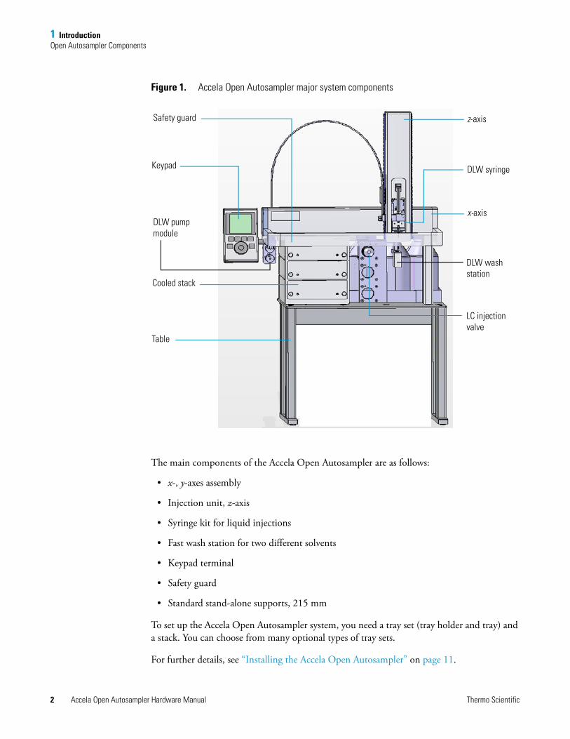
Figure 1. Accela Open Autosampler major system components
The main components of the Accela Open Autosampler are as follows:
• x-, y-axes assembly
• Injection unit, z-axis
• Syringe kit for liquid injections
• Fast wash station for two different solvents
• Keypad terminal
• Safety guard
• Standard stand-alone supports, 215 mm
To set up the Accela Open Autosampler system, you need a tray set (tray holder and tray) and a stack. You can choose from many optional types of tray sets.
For further details, see “Installing the Accela Open Autosampler” on page 11.
x-axis
z-axis
DLW syringe
DLW wash station
LC injection valve
Safety guard
Keypad
DLW pump module
Cooled stack
Table
1 IntroductionOpen Autosampler Components
Thermo Scientific Accela Open Autosampler Hardware Manual 3
Dynamic Load and Wash (DLW)
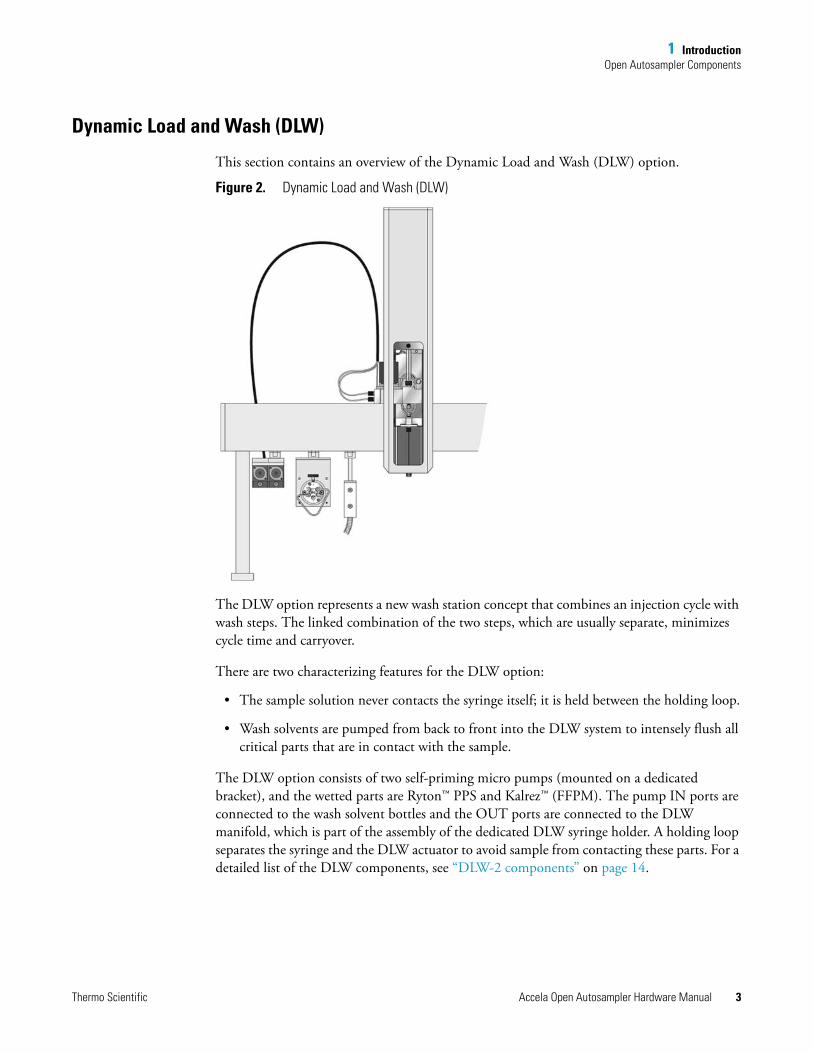
This section contains an overview of the Dynamic Load and Wash (DLW) option.
Figure 2. Dynamic Load and Wash (DLW)
The DLW option represents a new wash station concept that combines an injection cycle with wash steps. The linked combination of the two steps, which are usually separate, minimizes cycle time and carryover.
There are two characterizing features for the DLW option:
• The sample solution never contacts the syringe itself; it is held between the holding loop.
• Wash solvents are pumped from back to front into the DLW system to intensely flush all critical parts that are in contact with the sample.
The DLW option consists of two self-priming micro pumps (mounted on a dedicated bracket), and the wetted parts are Ryton™ PPS and Kalrez™ (FFPM). The pump IN ports are connected to the wash solvent bottles and the OUT ports are connected to the DLW manifold, which is part of the assembly of the dedicated DLW syringe holder. A holding loop separates the syringe and the DLW actuator to avoid sample from contacting these parts. For a detailed list of the DLW components, see “DLW-2 components” on page 14.
1 IntroductionOpen Autosampler Components
4 Accela Open Autosampler Hardware Manual Thermo Scientific
The syringe and holding loop are preloaded with wash solvent #1 at the start. The sample is picked up and remains separated from wash solvent #1 by an air gap. After loading the loop and injection, wash solvent #1 is pushed into the system, followed directly by wash solvent #2 to flush the critical valve paths.
The DLW syringe assembly is moved to the wash station for further cleaning steps and for preparing the Syringe and holding loop for the next cycle.
For further details, see “DLW Cycle Step-By-Step” on page 96.
There has been continuous development on the DLW option. The current version, DLW-2, has the following improvements over the DLW option:
• Holding Loop
The DLW-2 Holding Loop consists of one single piece from the needle to the loop, which eliminates several tube connections and replaces the needle and flow diverter. The Holding Loop is made of high-quality stainless steel and the inner surface is passivated with acid.
• DLW Syringe Holder back plate
The DLW-2 Syringe Holder back plate has changed in size and form to allow a replacement of the Holding Loop. The Actuator is supported fromt the back side to provide higher mechanical stability.
• DLW Pump Assembly
The DLW-2 Pump Assembly is equipped with a housing to protect the electrical parts from solvent splashes.
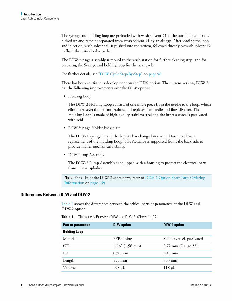
Differences Between DLW and DLW-2
Table 1 shows the differences between the critical parts or parameters of the DLW and DLW-2 option.
Note For a list of the DLW-2 spare parts, refer to DLW-2 Option Spare Parts Ordering Information on page 159
Table 1. Differences Between DLW and DLW-2 (Sheet 1 of 2)
Part or parameter DLW option DLW-2 option
Holding Loop
Material FEP tubing Stainless steel, passivated
OD 1/16" (1.58 mm) 0.72 mm (Gauge 22)
ID 0.50 mm 0.41 mm
Length 550 mm 855 mm
Volume 108 μL 118 μL
1 IntroductionOpen Autosampler Components
Thermo Scientific Accela Open Autosampler Hardware Manual 5
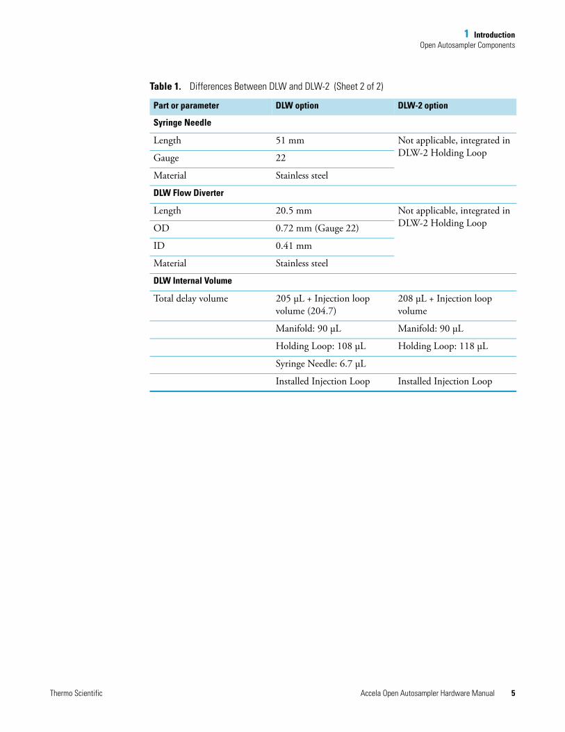
Syringe Needle
Length 51 mm Not applicable, integrated in DLW-2 Holding LoopGauge 22
Material Stainless steel
DLW Flow Diverter
Length 20.5 mm Not applicable, integrated in DLW-2 Holding LoopOD 0.72 mm (Gauge 22)
ID 0.41 mm
Material Stainless steel
DLW Internal Volume
Total delay volume 205 μL + Injection loop volume (204.7)
208 μL + Injection loop volume
Manifold: 90 μL Manifold: 90 μL
Holding Loop: 108 μL Holding Loop: 118 μL
Syringe Needle: 6.7 μL
Installed Injection Loop Installed Injection Loop
Table 1. Differences Between DLW and DLW-2 (Sheet 2 of 2)
Part or parameter DLW option DLW-2 option
1 IntroductionSpecifications
6 Accela Open Autosampler Hardware Manual Thermo Scientific
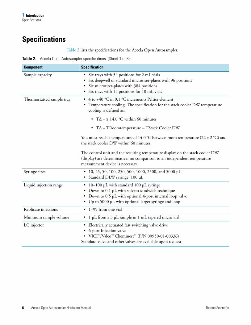
SpecificationsTable 2 lists the specifications for the Accela Open Autosampler.
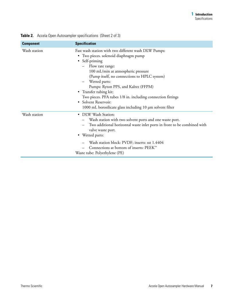
Table 2. Accela Open Autosampler specifications (Sheet 1 of 3)
Component Specification
Sample capacity • Six trays with 54 positions for 2 mL vials• Six deepwell or standard microtiter-plates with 96 positions• Six microtiter-plates with 384 positions• Six trays with 15 positions for 10 mL vials
Thermostatted sample tray • 4 to +40 °C in 0.1 °C increments Peltier element• Temperature cooling: The specification for the stack cooler DW temperature
cooling is defined as:
• TΔ = ≥ 14.0 °C within 60 minutes
• TΔ = TRoomtemperature – TStack Cooler DW
You must reach a temperature of 14.0 °C between room temperature (22 ± 2 °C) and the stack cooler DW within 60 minutes.
The control unit and the resulting temperature display on the stack cooler DW (display) are determinative; no comparison to an independent temperature measurement device is necessary.
Syringe sizes • 10, 25, 50, 100, 250, 500, 1000, 2500, and 5000 μL• Standard DLW syringe: 100 μL
Liquid injection range • 10–100 μL with standard 100 μL syringe• Down to 0.1 μL with solvent sandwich technique• Down to 0.5 μL with optional 4-port internal loop valve• Up to 5000 μL with optional larger syringe and loop
Replicate injections • 1–99 from one vial
Minimum sample volume • 1 μL from a 3 μL sample in 1 mL tapered micro vial
LC injector • Electrically actuated fast switching valve drive• 6-port Injection valve • VICI™/Valco™ Cheminert™ (P/N 00950-01-00336)
Standard valve and other valves are available upon request.
1 IntroductionSpecifications
Thermo Scientific Accela Open Autosampler Hardware Manual 7
Wash station Fast wash station with two different wash DLW Pumps:• Two pieces. solenoid diaphragm pump• Self-priming
– Flow rate range: 100 mL/min at atmospheric pressure(Pump itself, no connections to HPLC system)
– Wetted parts:Pumps: Ryton PPS, and Kalrez (FFPM)
• Transfer tubing kit: Two pieces. PFA tubes 1/8 in. including connection fittings
• Solvent Reservoir:1000 mL borosilicate glass including 10 μm solvent filter
Wash station • DLW Wash Station: – Wash station with two solvent ports and one waste port. – Two additional horizontal waste inlet ports in front to be combined with
valve waste port.• Wetted parts:
– Wash station block: PVDF; inserts: sst 1.4404– Connections at bottom of inserts: PEEK™
Waste tube: Polyethylene (PE)
Table 2. Accela Open Autosampler specifications (Sheet 2 of 3)
Component Specification
1 IntroductionPhysical Specifications
8 Accela Open Autosampler Hardware Manual Thermo Scientific
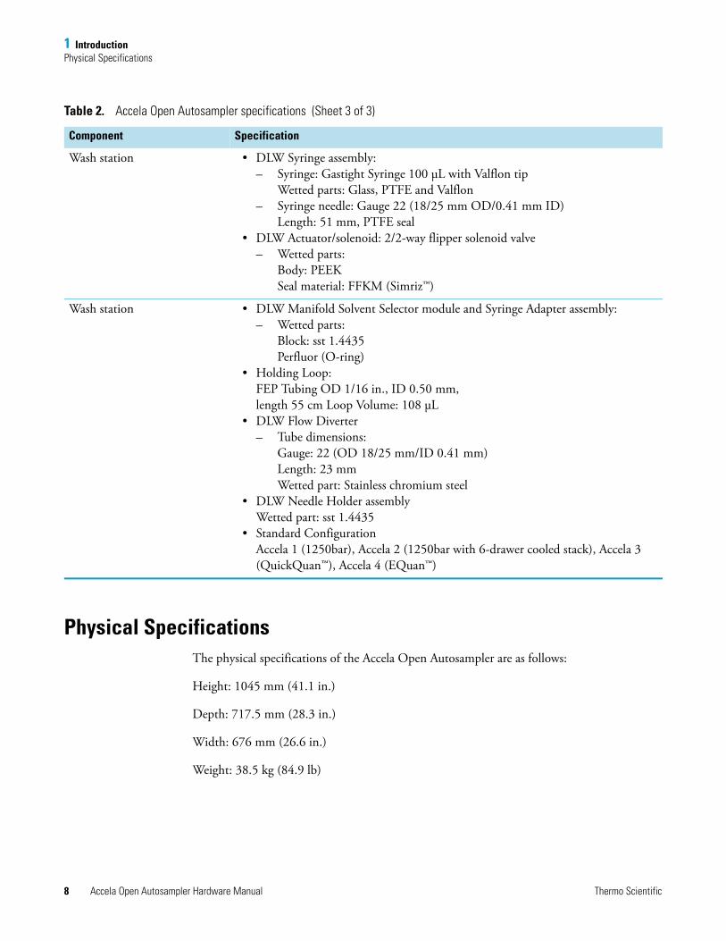
Physical SpecificationsThe physical specifications of the Accela Open Autosampler are as follows:
Height: 1045 mm (41.1 in.)
Depth: 717.5 mm (28.3 in.)
Width: 676 mm (26.6 in.)
Weight: 38.5 kg (84.9 lb)
Wash station • DLW Syringe assembly: – Syringe: Gastight Syringe 100 μL with Valflon tip
Wetted parts: Glass, PTFE and Valflon– Syringe needle: Gauge 22 (18/25 mm OD/0.41 mm ID)
Length: 51 mm, PTFE seal• DLW Actuator/solenoid: 2/2-way flipper solenoid valve
– Wetted parts: Body: PEEK Seal material: FFKM (Simriz™)
Wash station • DLW Manifold Solvent Selector module and Syringe Adapter assembly:– Wetted parts:
Block: sst 1.4435Perfluor (O-ring)
• Holding Loop:FEP Tubing OD 1/16 in., ID 0.50 mm, length 55 cm Loop Volume: 108 μL
• DLW Flow Diverter– Tube dimensions:
Gauge: 22 (OD 18/25 mm/ID 0.41 mm)Length: 23 mmWetted part: Stainless chromium steel
• DLW Needle Holder assembly Wetted part: sst 1.4435
• Standard ConfigurationAccela 1 (1250bar), Accela 2 (1250bar with 6-drawer cooled stack), Accela 3 (QuickQuan™), Accela 4 (EQuan™)
Table 2. Accela Open Autosampler specifications (Sheet 3 of 3)
Component Specification
1 IntroductionOperating and Environmental Requirements
Thermo Scientific Accela Open Autosampler Hardware Manual 9
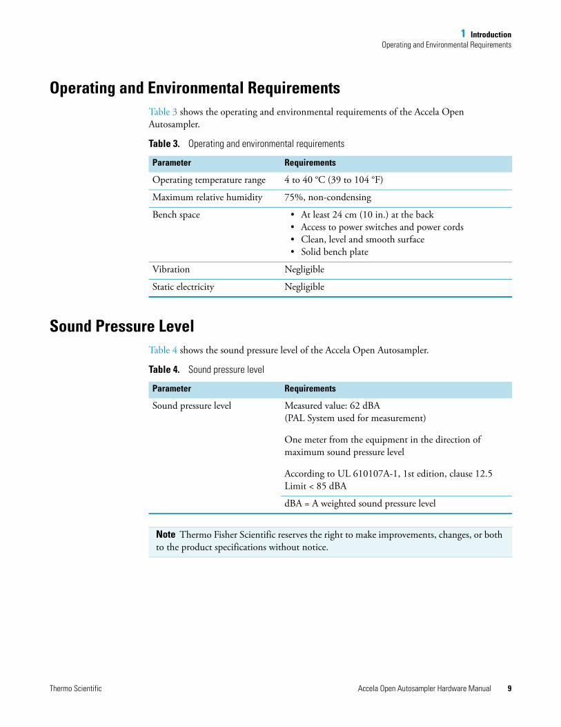
Operating and Environmental RequirementsTable 3 shows the operating and environmental requirements of the Accela Open Autosampler.
Sound Pressure Level Table 4 shows the sound pressure level of the Accela Open Autosampler.
Table 3. Operating and environmental requirements
Parameter Requirements
Operating temperature range 4 to 40 °C (39 to 104 °F)
Maximum relative humidity 75%, non-condensing
Bench space • At least 24 cm (10 in.) at the back• Access to power switches and power cords• Clean, level and smooth surface• Solid bench plate
Vibration Negligible
Static electricity Negligible
Table 4. Sound pressure level
Parameter Requirements
Sound pressure level Measured value: 62 dBA(PAL System used for measurement)
One meter from the equipment in the direction of maximum sound pressure level
According to UL 610107A-1, 1st edition, clause 12.5 Limit < 85 dBA
dBA = A weighted sound pressure level
Note Thermo Fisher Scientific reserves the right to make improvements, changes, or both to the product specifications without notice.

Thermo Scientific Accela Open Autosampler Hardware Manual 11
2
Installing the Accela Open Autosampler
This chapter describes the installation, contact closure cable connection, computer connection, object positions, and injection valve of the Accela Open Autosampler.
Installing the Autosampler and DLWThis section contains information about unpacking components and assembling the open autosampler, installing the DLW, electrical connections, and the cool stack.
Unpacking the Components
An Accela Open Autosampler system is shipped in four boxes. The contents of these boxes are as follows:
Box 1: Contains the x-, y-axes assembly, the injection unit, keypad terminal, stand-alone supports, connecting cables, power supply, syringe kit, wash station assembly, safety guard, and miscellaneous parts. See “Open Autosampler Components” on page 1.
Box 2: Contains the DLW injection kit.
Box 3: Contains the cooled stack.
Box 4: Contains the Accela Open Autosampler table.
Contents
• Installing the Autosampler and DLW
• System Synchronization Connections
• Connecting the Accela Open Autosampler to the Data System Computer
• Accela Open Autosampler Object Positions
• Injection Valve
2 Installing the Accela Open AutosamplerInstalling the Autosampler and DLW
12 Accela Open Autosampler Hardware Manual Thermo Scientific
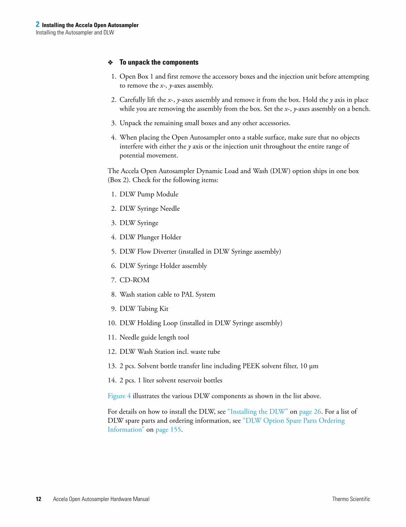
To unpack the components
1. Open Box 1 and first remove the accessory boxes and the injection unit before attempting to remove the x-, y-axes assembly.
2. Carefully lift the x-, y-axes assembly and remove it from the box. Hold the y axis in place while you are removing the assembly from the box. Set the x-, y-axes assembly on a bench.
3. Unpack the remaining small boxes and any other accessories.
4. When placing the Open Autosampler onto a stable surface, make sure that no objects interfere with either the y axis or the injection unit throughout the entire range of potential movement.
The Accela Open Autosampler Dynamic Load and Wash (DLW) option ships in one box (Box 2). Check for the following items:
1. DLW Pump Module
2. DLW Syringe Needle
3. DLW Syringe
4. DLW Plunger Holder
5. DLW Flow Diverter (installed in DLW Syringe assembly)
6. DLW Syringe Holder assembly
7. CD-ROM
8. Wash station cable to PAL System
9. DLW Tubing Kit
10. DLW Holding Loop (installed in DLW Syringe assembly)
11. Needle guide length tool
12. DLW Wash Station incl. waste tube
13. 2 pcs. Solvent bottle transfer line including PEEK solvent filter, 10 μm
14. 2 pcs. 1 liter solvent reservoir bottles
Figure 4 illustrates the various DLW components as shown in the list above.
For details on how to install the DLW, see “Installing the DLW” on page 26. For a list of DLW spare parts and ordering information, see “DLW Option Spare Parts Ordering Information” on page 155.
2 Installing the Accela Open AutosamplerInstalling the Autosampler and DLW
Thermo Scientific Accela Open Autosampler Hardware Manual 13
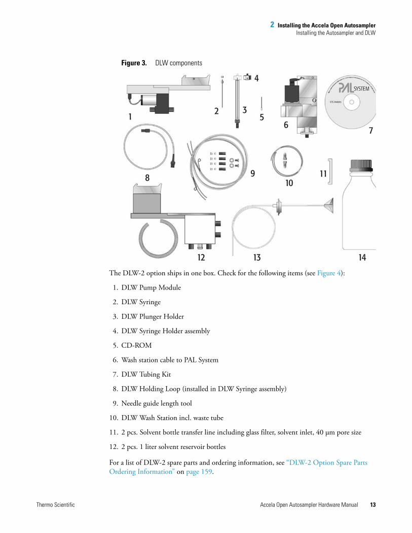
Figure 3. DLW components
The DLW-2 option ships in one box. Check for the following items (see Figure 4):
1. DLW Pump Module
2. DLW Syringe
3. DLW Plunger Holder
4. DLW Syringe Holder assembly
5. CD-ROM
6. Wash station cable to PAL System
7. DLW Tubing Kit
8. DLW Holding Loop (installed in DLW Syringe assembly)
9. Needle guide length tool
10. DLW Wash Station incl. waste tube
11. 2 pcs. Solvent bottle transfer line including glass filter, solvent inlet, 40 μm pore size
12. 2 pcs. 1 liter solvent reservoir bottles
For a list of DLW-2 spare parts and ordering information, see “DLW-2 Option Spare Parts Ordering Information” on page 159.
2 Installing the Accela Open AutosamplerInstalling the Autosampler and DLW
14 Accela Open Autosampler Hardware Manual Thermo Scientific
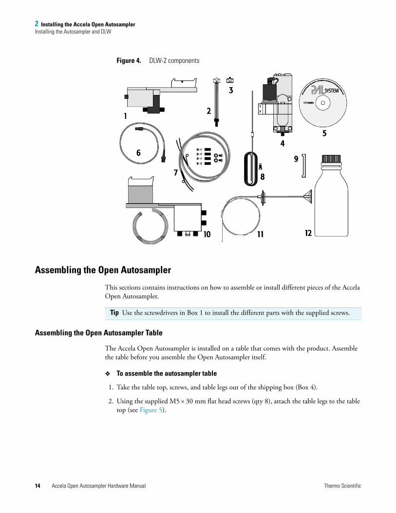
Figure 4. DLW-2 components
Assembling the Open Autosampler
This sections contains instructions on how to assemble or install different pieces of the Accela Open Autosampler.
Assembling the Open Autosampler Table
The Accela Open Autosampler is installed on a table that comes with the product. Assemble the table before you assemble the Open Autosampler itself.
To assemble the autosampler table
1. Take the table top, screws, and table legs out of the shipping box (Box 4).
2. Using the supplied M5 × 30 mm flat head screws (qty 8), attach the table legs to the table top (see Figure 5).
Tip Use the screwdrivers in Box 1 to install the different parts with the supplied screws.
2 Installing the Accela Open AutosamplerInstalling the Autosampler and DLW
Thermo Scientific Accela Open Autosampler Hardware Manual 15
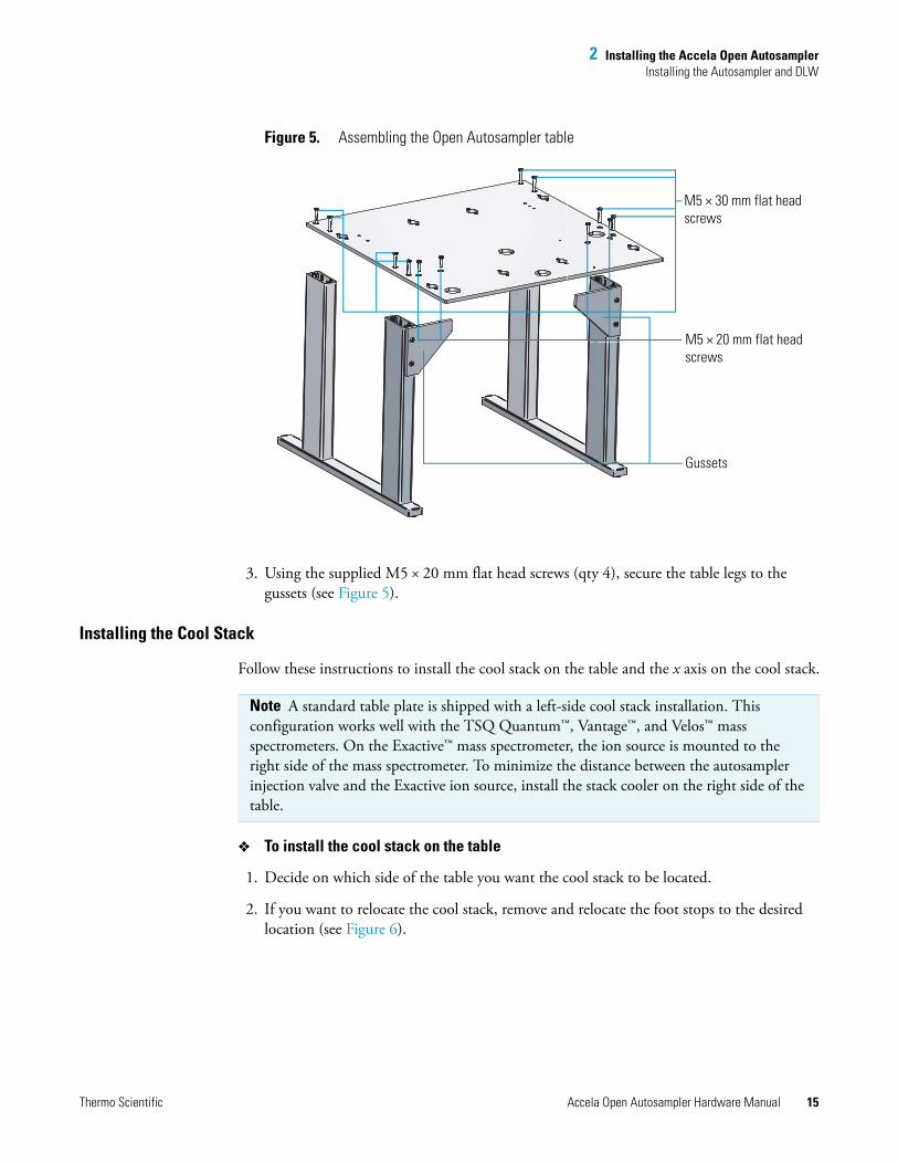
Figure 5. Assembling the Open Autosampler table
3. Using the supplied M5 × 20 mm flat head screws (qty 4), secure the table legs to the gussets (see Figure 5).
Installing the Cool Stack
Follow these instructions to install the cool stack on the table and the x axis on the cool stack.
To install the cool stack on the table
1. Decide on which side of the table you want the cool stack to be located.
2. If you want to relocate the cool stack, remove and relocate the foot stops to the desired location (see Figure 6).
AM5 × 30 mm flat head screws
M5 × 20 mm flat head screws
Gussets
Note A standard table plate is shipped with a left-side cool stack installation. This configuration works well with the TSQ Quantum™, Vantage™, and Velos™ mass spectrometers. On the Exactive™ mass spectrometer, the ion source is mounted to the right side of the mass spectrometer. To minimize the distance between the autosampler injection valve and the Exactive ion source, install the stack cooler on the right side of the table.
2 Installing the Accela Open AutosamplerInstalling the Autosampler and DLW
16 Accela Open Autosampler Hardware Manual Thermo Scientific
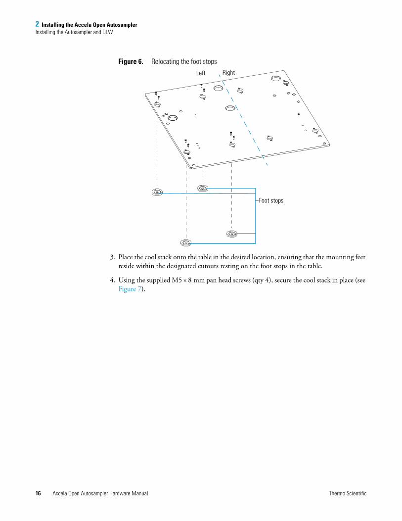
Figure 6. Relocating the foot stops
3. Place the cool stack onto the table in the desired location, ensuring that the mounting feet reside within the designated cutouts resting on the foot stops in the table.
4. Using the supplied M5 × 8 mm pan head screws (qty 4), secure the cool stack in place (see Figure 7).
RightLeft
Foot stops
2 Installing the Accela Open AutosamplerInstalling the Autosampler and DLW
Thermo Scientific Accela Open Autosampler Hardware Manual 17
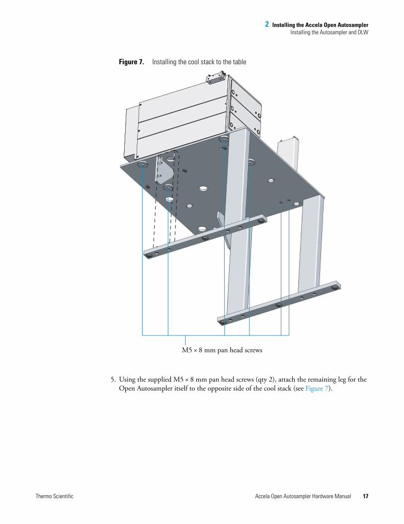
Figure 7. Installing the cool stack to the table
5. Using the supplied M5 × 8 mm pan head screws (qty 2), attach the remaining leg for the Open Autosampler itself to the opposite side of the cool stack (see Figure 7).
M5 × 8 mm pan head screws
2 Installing the Accela Open AutosamplerInstalling the Autosampler and DLW
18 Accela Open Autosampler Hardware Manual Thermo Scientific
To install the x axis on the cool stack
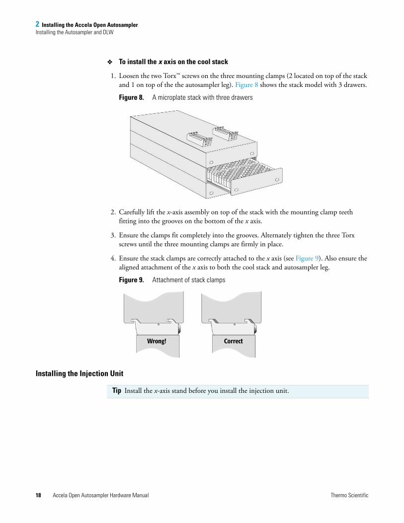
1. Loosen the two Torx™ screws on the three mounting clamps (2 located on top of the stack and 1 on top of the the autosampler leg). Figure 8 shows the stack model with 3 drawers.
Figure 8. A microplate stack with three drawers
2. Carefully lift the x-axis assembly on top of the stack with the mounting clamp teeth fitting into the grooves on the bottom of the x axis.
3. Ensure the clamps fit completely into the grooves. Alternately tighten the three Torx screws until the three mounting clamps are firmly in place.
4. Ensure the stack clamps are correctly attached to the x axis (see Figure 9). Also ensure the aligned attachment of the x axis to both the cool stack and autosampler leg.
Figure 9. Attachment of stack clamps
Installing the Injection Unit
Tip Install the x-axis stand before you install the injection unit.
2 Installing the Accela Open AutosamplerInstalling the Autosampler and DLW
Thermo Scientific Accela Open Autosampler Hardware Manual 19
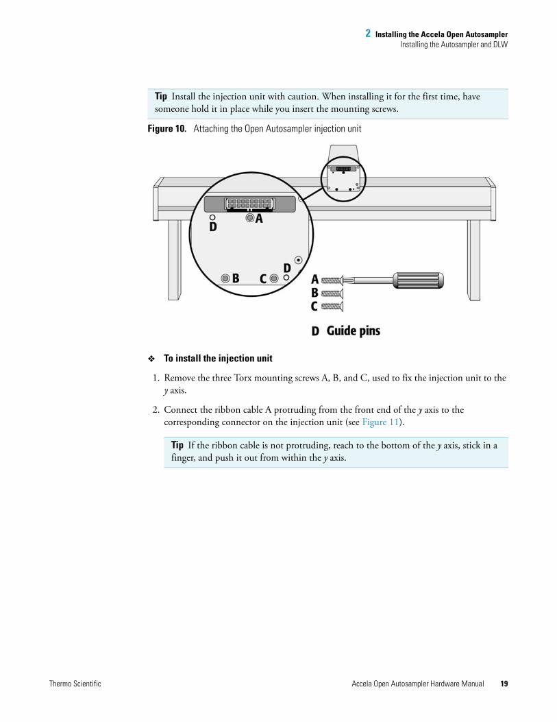
Figure 10. Attaching the Open Autosampler injection unit
To install the injection unit
1. Remove the three Torx mounting screws A, B, and C, used to fix the injection unit to the y axis.
2. Connect the ribbon cable A protruding from the front end of the y axis to the corresponding connector on the injection unit (see Figure 11).
Tip Install the injection unit with caution. When installing it for the first time, have someone hold it in place while you insert the mounting screws.
Tip If the ribbon cable is not protruding, reach to the bottom of the y axis, stick in a finger, and push it out from within the y axis.
2 Installing the Accela Open AutosamplerInstalling the Autosampler and DLW
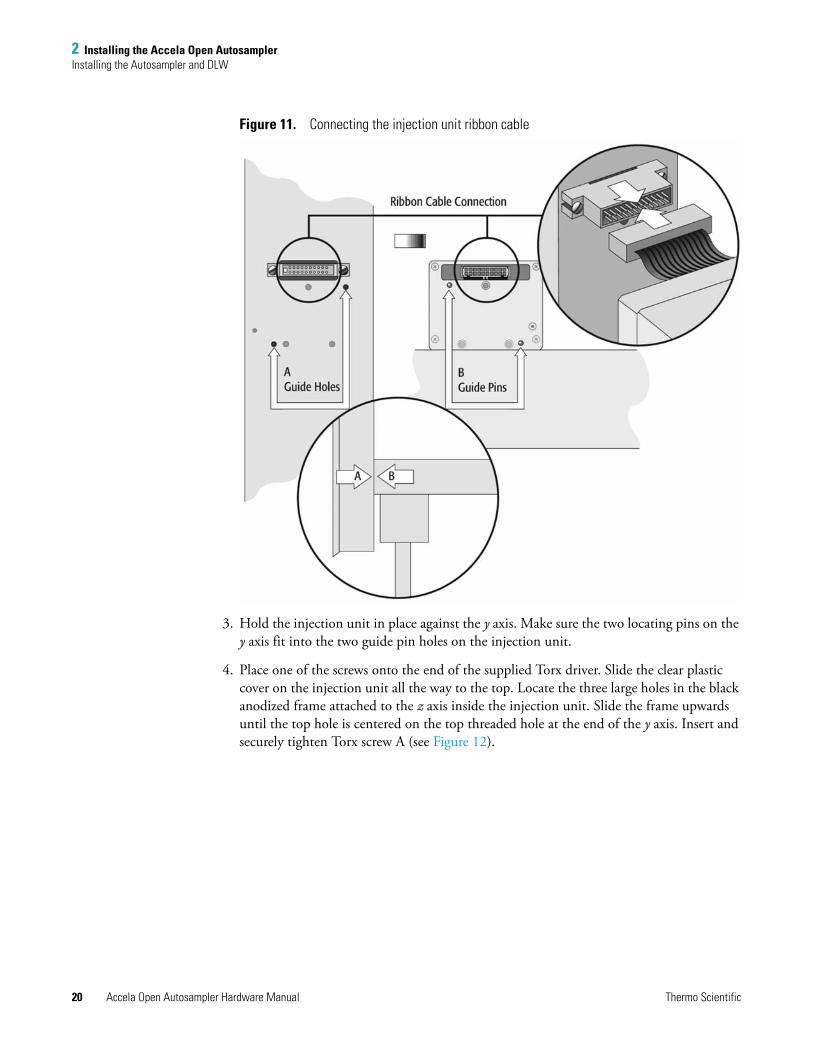
20 Accela Open Autosampler Hardware Manual Thermo Scientific
Figure 11. Connecting the injection unit ribbon cable
3. Hold the injection unit in place against the y axis. Make sure the two locating pins on the y axis fit into the two guide pin holes on the injection unit.
4. Place one of the screws onto the end of the supplied Torx driver. Slide the clear plastic cover on the injection unit all the way to the top. Locate the three large holes in the black anodized frame attached to the z axis inside the injection unit. Slide the frame upwards until the top hole is centered on the top threaded hole at the end of the y axis. Insert and securely tighten Torx screw A (see Figure 12).
2 Installing the Accela Open AutosamplerInstalling the Autosampler and DLW
Thermo Scientific Accela Open Autosampler Hardware Manual 21
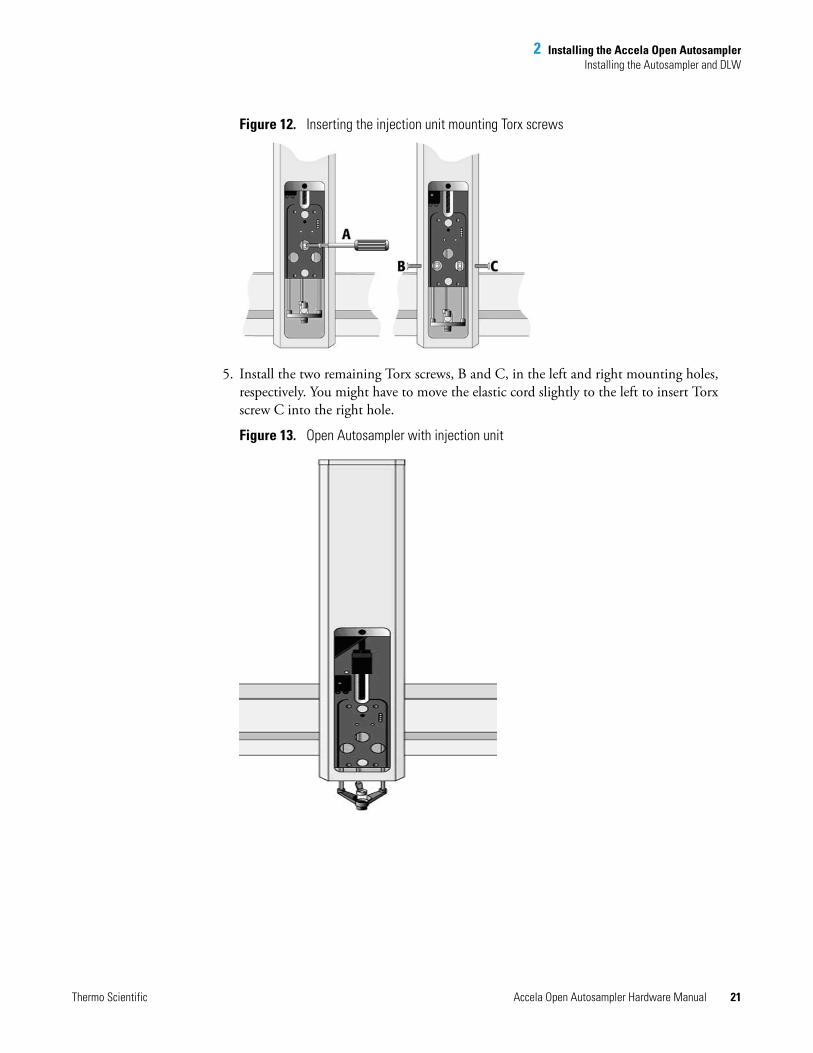
Figure 12. Inserting the injection unit mounting Torx screws
5. Install the two remaining Torx screws, B and C, in the left and right mounting holes, respectively. You might have to move the elastic cord slightly to the left to insert Torx screw C into the right hole.
Figure 13. Open Autosampler with injection unit
2 Installing the Accela Open AutosamplerInstalling the Autosampler and DLW
22 Accela Open Autosampler Hardware Manual Thermo Scientific
Installing the Keypad Terminal
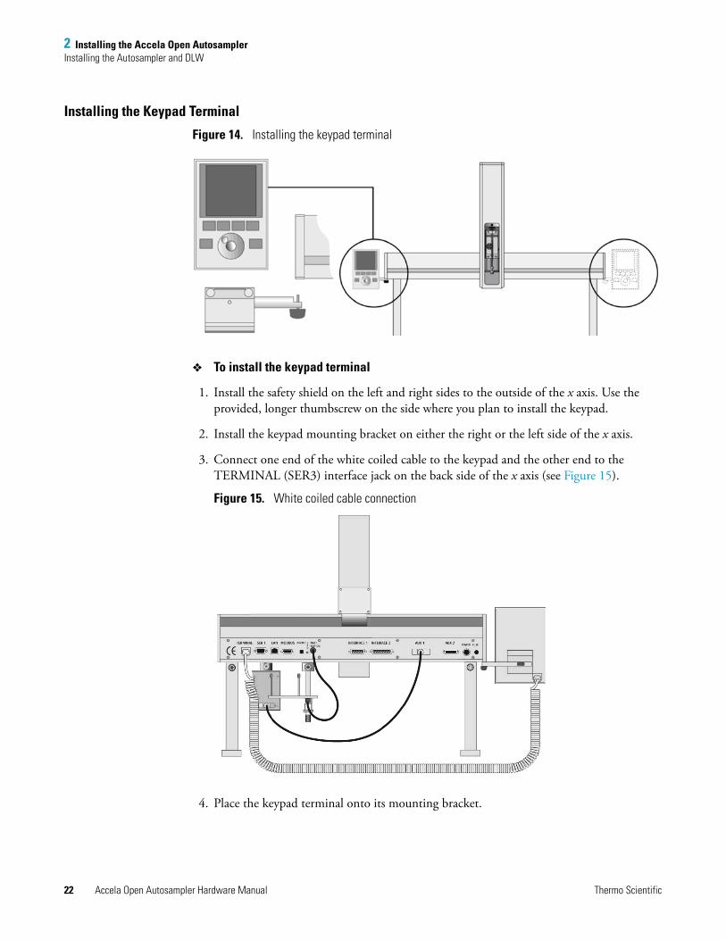
Figure 14. Installing the keypad terminal
To install the keypad terminal
1. Install the safety shield on the left and right sides to the outside of the x axis. Use the provided, longer thumbscrew on the side where you plan to install the keypad.
2. Install the keypad mounting bracket on either the right or the left side of the x axis.
3. Connect one end of the white coiled cable to the keypad and the other end to the TERMINAL (SER3) interface jack on the back side of the x axis (see Figure 15).
Figure 15. White coiled cable connection
4. Place the keypad terminal onto its mounting bracket.
2 Installing the Accela Open AutosamplerInstalling the Autosampler and DLW
Thermo Scientific Accela Open Autosampler Hardware Manual 23
Installing the Power Supply
To install the power supply
1. Locate the power supply, the DC power cable, and the AC power cable.
2. Set the power supply switch to OFF.
3. Connect one end of the DC power cable to the power supply and the other end to the POWER connector at the back of the x axis.
4. Connect the female end of the AC power cable to the power supply. Then connect the male end to an AC power outlet.
Installing the LC Injection Valve
To install the LC injection valve
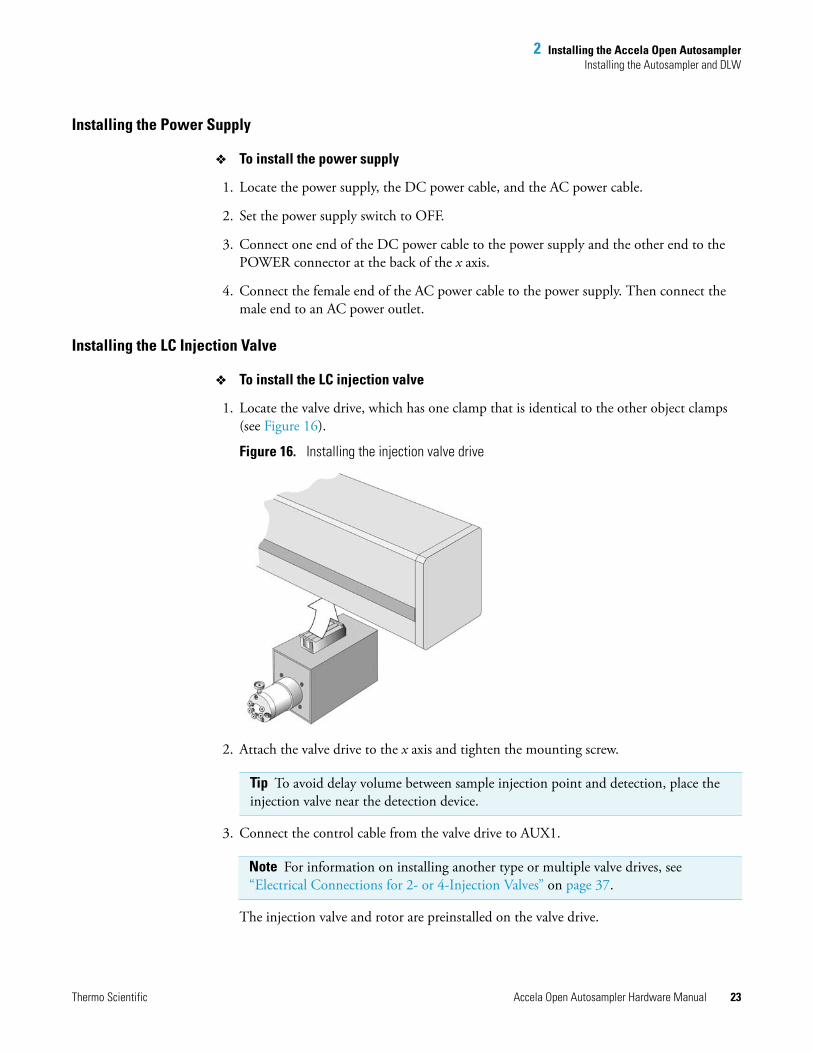
1. Locate the valve drive, which has one clamp that is identical to the other object clamps (see Figure 16).
Figure 16. Installing the injection valve drive
2. Attach the valve drive to the x axis and tighten the mounting screw.
3. Connect the control cable from the valve drive to AUX1.
The injection valve and rotor are preinstalled on the valve drive.
Tip To avoid delay volume between sample injection point and detection, place the injection valve near the detection device.
Note For information on installing another type or multiple valve drives, see “Electrical Connections for 2- or 4-Injection Valves” on page 37.
2 Installing the Accela Open AutosamplerInstalling the Autosampler and DLW
24 Accela Open Autosampler Hardware Manual Thermo Scientific
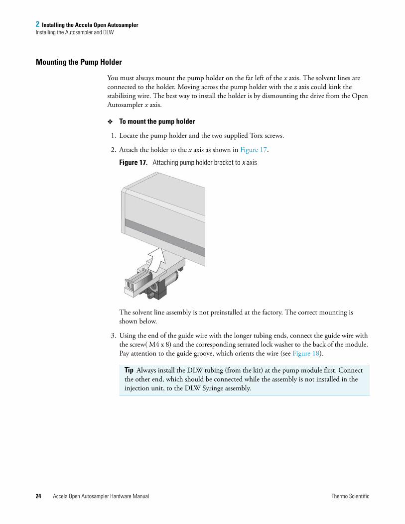
Mounting the Pump Holder
You must always mount the pump holder on the far left of the x axis. The solvent lines are connected to the holder. Moving across the pump holder with the z axis could kink the stabilizing wire. The best way to install the holder is by dismounting the drive from the Open Autosampler x axis.
To mount the pump holder
1. Locate the pump holder and the two supplied Torx screws.
2. Attach the holder to the x axis as shown in Figure 17.
Figure 17. Attaching pump holder bracket to x axis
The solvent line assembly is not preinstalled at the factory. The correct mounting is shown below.
3. Using the end of the guide wire with the longer tubing ends, connect the guide wire with the screw( M4 x 8) and the corresponding serrated lock washer to the back of the module. Pay attention to the guide groove, which orients the wire (see Figure 18).
Tip Always install the DLW tubing (from the kit) at the pump module first. Connect the other end, which should be connected while the assembly is not installed in the injection unit, to the DLW Syringe assembly.
2 Installing the Accela Open AutosamplerInstalling the Autosampler and DLW
Thermo Scientific Accela Open Autosampler Hardware Manual 25
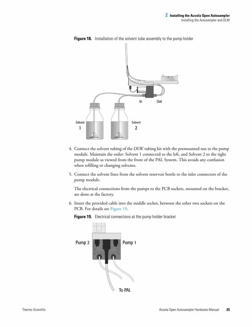
Figure 18. Installation of the solvent tube assembly to the pump holder
4. Connect the solvent tubing of the DLW tubing kit with the premounted nut to the pump module. Maintain the order: Solvent 1 connected to the left, and Solvent 2 to the right pump module as viewed from the front of the PAL System. This avoids any confusion when refilling or changing solvents.
5. Connect the solvent lines from the solvent reservoir bottle to the inlet connectors of the pump module.
The electrical connections from the pumps to the PCB sockets, mounted on the bracket, are done at the factory.
6. Insert the provided cable into the middle socket, between the other two sockets on the PCB. For details see Figure 19.
Figure 19. Electrical connections at the pump holder bracket
2 Installing the Accela Open AutosamplerInstalling the Autosampler and DLW
26 Accela Open Autosampler Hardware Manual Thermo Scientific
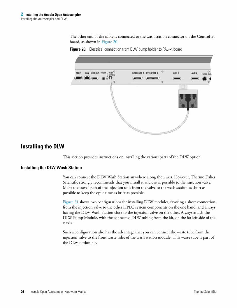
The other end of the cable is connected to the wash station connector on the Control-xt board, as shown in Figure 20.
Figure 20. Electrical connection from DLW pump holder to PAL-xt board
Installing the DLW
This section provides instructions on installing the various parts of the DLW option.
Installing the DLW Wash Station
You can connect the DLW Wash Station anywhere along the x axis. However, Thermo Fisher Scientific strongly recommends that you install it as close as possible to the injection valve. Make the travel path of the injection unit from the valve to the wash station as short as possible to keep the cycle time as brief as possible.
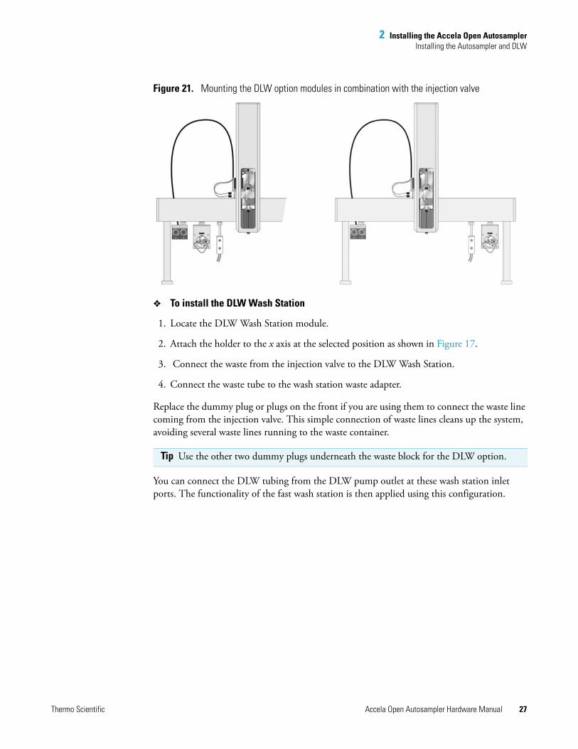
Figure 21 shows two configurations for installing DLW modules, favoring a short connection from the injection valve to the other HPLC system components on the one hand, and always having the DLW Wash Station close to the injection valve on the other. Always attach the DLW Pump Module, with the connected DLW tubing from the kit, on the far left side of the x axis.
Such a configuration also has the advantage that you can connect the waste tube from the injection valve to the front waste inlet of the wash station module. This waste tube is part of the DLW option kit.
2 Installing the Accela Open AutosamplerInstalling the Autosampler and DLW
Thermo Scientific Accela Open Autosampler Hardware Manual 27
Figure 21. Mounting the DLW option modules in combination with the injection valve
To install the DLW Wash Station
1. Locate the DLW Wash Station module.
2. Attach the holder to the x axis at the selected position as shown in Figure 17.
3. Connect the waste from the injection valve to the DLW Wash Station.
4. Connect the waste tube to the wash station waste adapter.
Replace the dummy plug or plugs on the front if you are using them to connect the waste line coming from the injection valve. This simple connection of waste lines cleans up the system, avoiding several waste lines running to the waste container.
You can connect the DLW tubing from the DLW pump outlet at these wash station inlet ports. The functionality of the fast wash station is then applied using this configuration.
Tip Use the other two dummy plugs underneath the waste block for the DLW option.
2 Installing the Accela Open AutosamplerInstalling the Autosampler and DLW
28 Accela Open Autosampler Hardware Manual Thermo Scientific
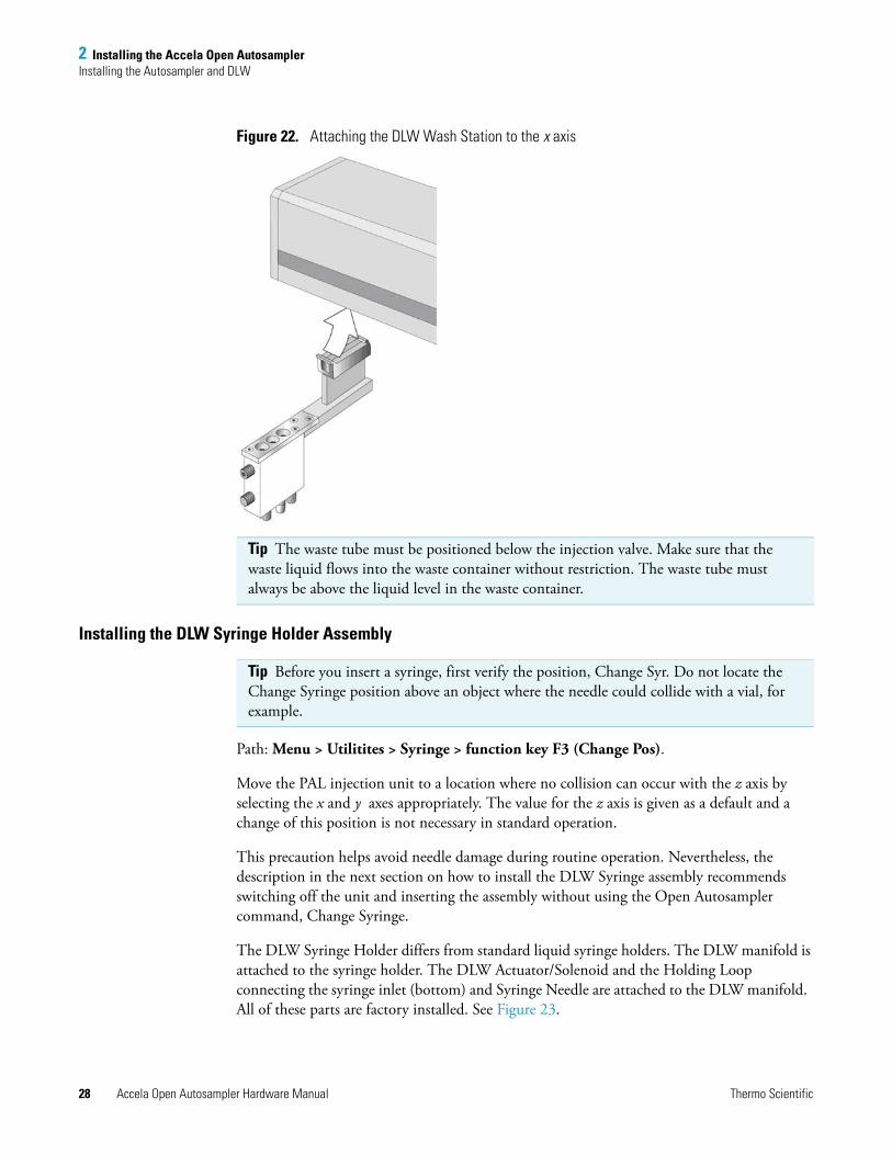
Figure 22. Attaching the DLW Wash Station to the x axis
Installing the DLW Syringe Holder Assembly
Path: Menu > Utilitites > Syringe > function key F3 (Change Pos).
Move the PAL injection unit to a location where no collision can occur with the z axis by selecting the x and y axes appropriately. The value for the z axis is given as a default and a change of this position is not necessary in standard operation.
This precaution helps avoid needle damage during routine operation. Nevertheless, the description in the next section on how to install the DLW Syringe assembly recommends switching off the unit and inserting the assembly without using the Open Autosampler command, Change Syringe.
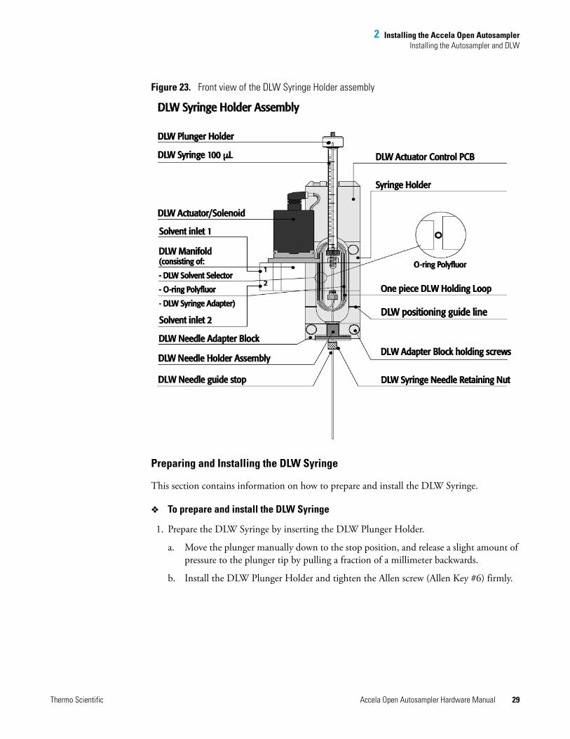
The DLW Syringe Holder differs from standard liquid syringe holders. The DLW manifold is attached to the syringe holder. The DLW Actuator/Solenoid and the Holding Loop connecting the syringe inlet (bottom) and Syringe Needle are attached to the DLW manifold. All of these parts are factory installed. See Figure 23.
Tip The waste tube must be positioned below the injection valve. Make sure that the waste liquid flows into the waste container without restriction. The waste tube must always be above the liquid level in the waste container.
Tip Before you insert a syringe, first verify the position, Change Syr. Do not locate the Change Syringe position above an object where the needle could collide with a vial, for example.
2 Installing the Accela Open AutosamplerInstalling the Autosampler and DLW
Thermo Scientific Accela Open Autosampler Hardware Manual 29
Figure 23. Front view of the DLW Syringe Holder assembly
Preparing and Installing the DLW Syringe
This section contains information on how to prepare and install the DLW Syringe.
To prepare and install the DLW Syringe
1. Prepare the DLW Syringe by inserting the DLW Plunger Holder.
a. Move the plunger manually down to the stop position, and release a slight amount of pressure to the plunger tip by pulling a fraction of a millimeter backwards.
b. Install the DLW Plunger Holder and tighten the Allen screw (Allen Key #6) firmly.
2 Installing the Accela Open AutosamplerInstalling the Autosampler and DLW
30 Accela Open Autosampler Hardware Manual Thermo Scientific
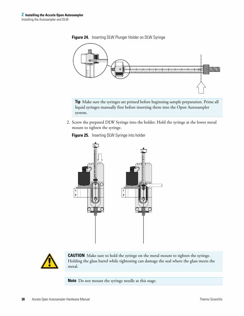
Figure 24. Inserting DLW Plunger Holder on DLW Syringe
2. Screw the prepared DLW Syringe into the holder. Hold the syringe at the lower metal mount to tighten the syringe.
Figure 25. Inserting DLW Syringe into holder
Tip Make sure the syringes are primed before beginning sample preparation. Prime all liquid syringes manually first before inserting them into the Open Autosampler system.
CAUTION Make sure to hold the syringe on the metal mount to tighten the syringe. Holding the glass barrel while tightening can damage the seal where the glass meets the metal.
Note Do not mount the syringe needle at this stage.
2 Installing the Accela Open AutosamplerInstalling the Autosampler and DLW
Thermo Scientific Accela Open Autosampler Hardware Manual 31
Connecting the DLW Tubing to the Syringe Holder
To connect the DLW tubing to the syringe holder
1. Connect the end of the sleeved tubing with the short tubes to the DLW Syringe Holder assembly. See “Mounting the Pump Holder ” on page 24.
2. Use the groove in the block at the back of the DLW Manifold to orient the guide wire. To connect, use the provided screw (M3×5) and the corresponding serrated lock washer.
3. Test to see if the wire tension is enough to keep the tubing in an upright position but low enough to move the syringe holder manually along the x axis.
4. Connect solvent line 1 to the upper port and solvent line 2 to the lower port at the left side of the DLW Manifold.
Make sure the order of the tube connections, upper or lower, is consistent. In certain applications you cannot mix types of solvents; for example, biofluid sample solution should not come in contact with highly concentrated organic solvents.
Note Thermo Fisher Scientific recommends connecting the DLW tubing from the kit to the syringe holder while the assembly is not inserted in the x axis.
Note The wetted parts of the DLW Actuator/Solenoid are PEEK for the body and FFKM (Simriz) for the seal material.
PEEK tubing exhibits excellent chemical resistance to most of the chemicals used. However, the following solvents are not recommended for use with PEEK: DMSO, THF, methylene chloride (dichloromethane), nitric acid, or sulfuric acid. For more details, refer to the compatibility tables provided by the manufacturer of PEEK material or components.
Note The design of the DLW Manifold and the concept of washing by active pumping and active closing of the lines by the DLW Actuator theoretically do not require a predefined solvent line position.
A problem could occur if solvent is refilled or exchanged while the tubing still contains solvent from the previous setup. Always keep the lines at the same position, and prime the entire system with caution to prevent unnecessary confusion. For further details, see Chapter 5, “Operating Dynamic Load and Wash (DLW).”
2 Installing the Accela Open AutosamplerInstalling the Autosampler and DLW
32 Accela Open Autosampler Hardware Manual Thermo Scientific
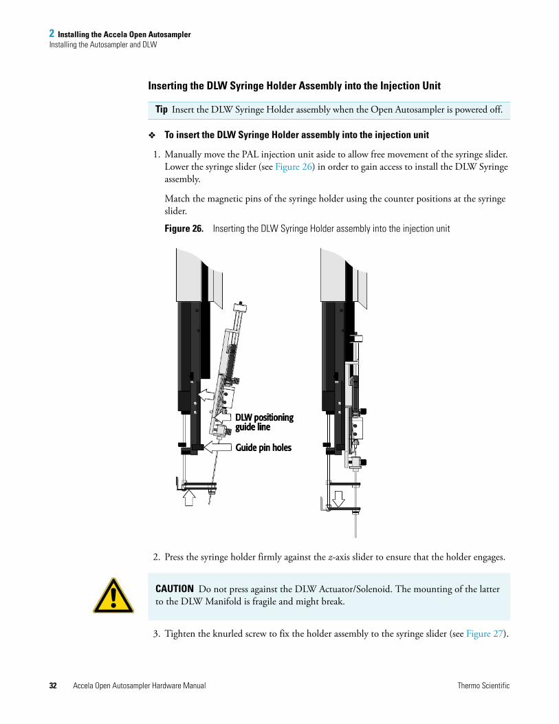
Inserting the DLW Syringe Holder Assembly into the Injection Unit
To insert the DLW Syringe Holder assembly into the injection unit
1. Manually move the PAL injection unit aside to allow free movement of the syringe slider. Lower the syringe slider (see Figure 26) in order to gain access to install the DLW Syringe assembly.
Match the magnetic pins of the syringe holder using the counter positions at the syringe slider.
Figure 26. Inserting the DLW Syringe Holder assembly into the injection unit
2. Press the syringe holder firmly against the z-axis slider to ensure that the holder engages.
3. Tighten the knurled screw to fix the holder assembly to the syringe slider (see Figure 27).
Tip Insert the DLW Syringe Holder assembly when the Open Autosampler is powered off.
CAUTION Do not press against the DLW Actuator/Solenoid. The mounting of the latter to the DLW Manifold is fragile and might break.
2 Installing the Accela Open AutosamplerInstalling the Autosampler and DLW
Thermo Scientific Accela Open Autosampler Hardware Manual 33
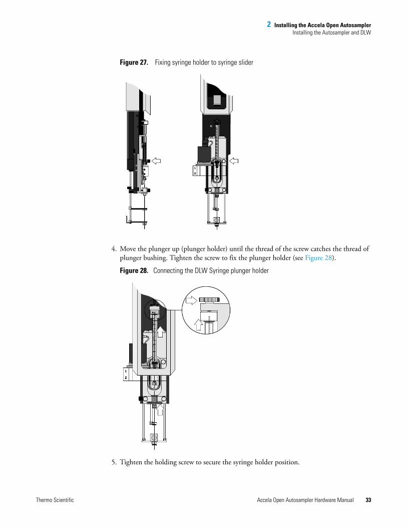
Figure 27. Fixing syringe holder to syringe slider
4. Move the plunger up (plunger holder) until the thread of the screw catches the thread of plunger bushing. Tighten the screw to fix the plunger holder (see Figure 28).
Figure 28. Connecting the DLW Syringe plunger holder
5. Tighten the holding screw to secure the syringe holder position.
2 Installing the Accela Open AutosamplerInstalling the Autosampler and DLW
34 Accela Open Autosampler Hardware Manual Thermo Scientific
6. Move the lower needle guide carefully up and down to make sure that the needle tip does not catch on the guide.
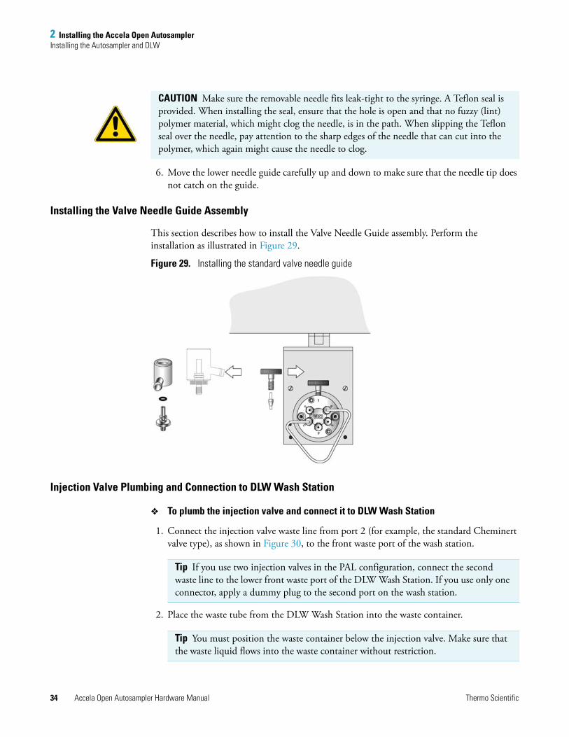
Installing the Valve Needle Guide Assembly
This section describes how to install the Valve Needle Guide assembly. Perform the installation as illustrated in Figure 29.
Figure 29. Installing the standard valve needle guide
Injection Valve Plumbing and Connection to DLW Wash Station
To plumb the injection valve and connect it to DLW Wash Station
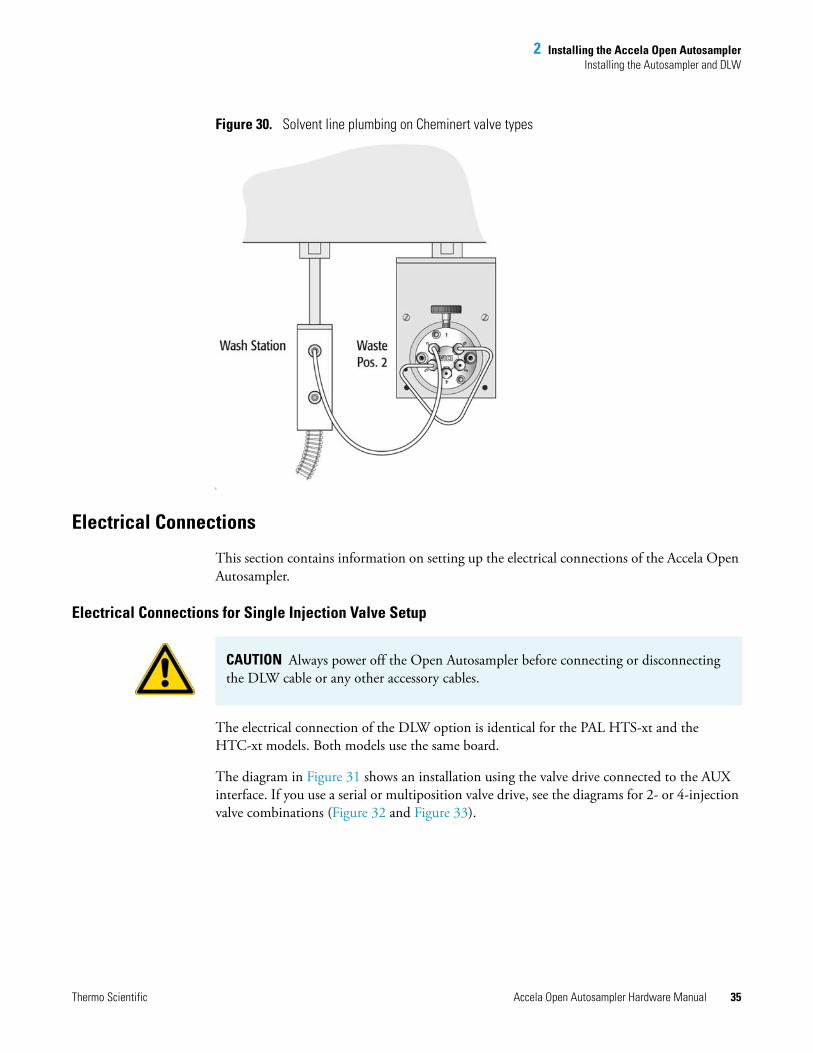
1. Connect the injection valve waste line from port 2 (for example, the standard Cheminert valve type), as shown in Figure 30, to the front waste port of the wash station.
2. Place the waste tube from the DLW Wash Station into the waste container.
CAUTION Make sure the removable needle fits leak-tight to the syringe. A Teflon seal is provided. When installing the seal, ensure that the hole is open and that no fuzzy (lint) polymer material, which might clog the needle, is in the path. When slipping the Teflon seal over the needle, pay attention to the sharp edges of the needle that can cut into the polymer, which again might cause the needle to clog.
Tip If you use two injection valves in the PAL configuration, connect the second waste line to the lower front waste port of the DLW Wash Station. If you use only one connector, apply a dummy plug to the second port on the wash station.
Tip You must position the waste container below the injection valve. Make sure that the waste liquid flows into the waste container without restriction.
2 Installing the Accela Open AutosamplerInstalling the Autosampler and DLW
Thermo Scientific Accela Open Autosampler Hardware Manual 35
Figure 30. Solvent line plumbing on Cheminert valve types
).
Electrical Connections
This section contains information on setting up the electrical connections of the Accela Open Autosampler.
Electrical Connections for Single Injection Valve Setup
The electrical connection of the DLW option is identical for the PAL HTS-xt and the HTC-xt models. Both models use the same board.
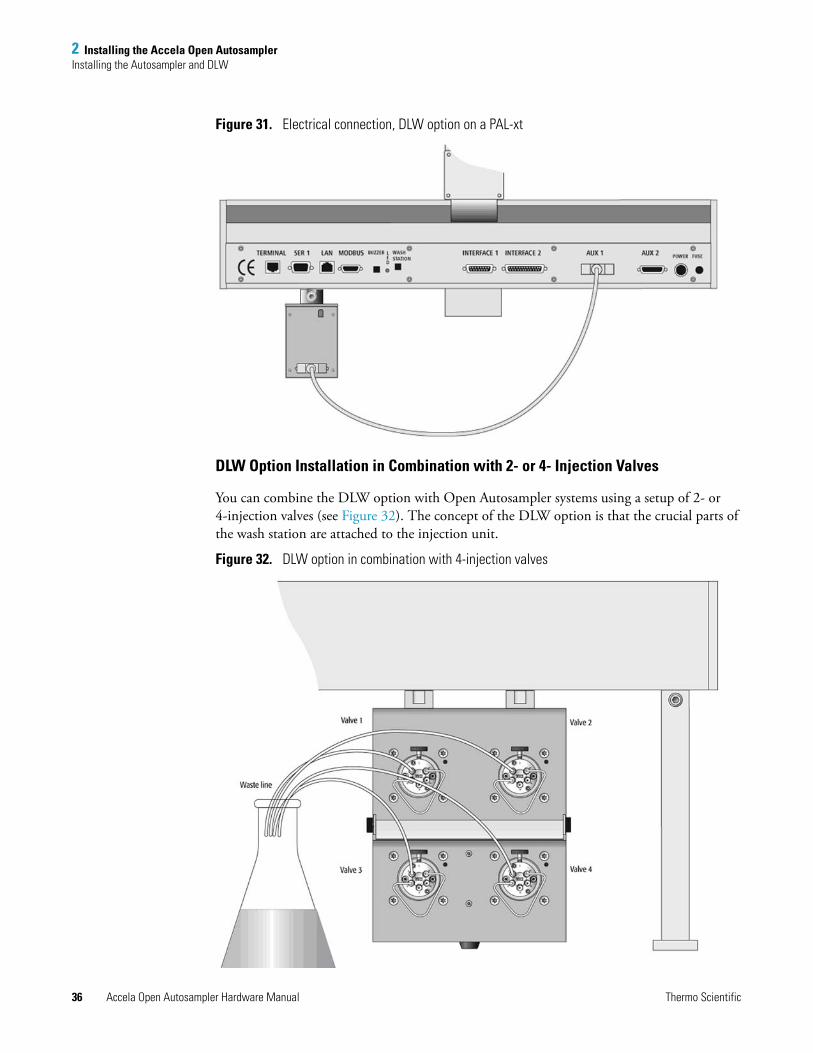
The diagram in Figure 31 shows an installation using the valve drive connected to the AUX interface. If you use a serial or multiposition valve drive, see the diagrams for 2- or 4-injection valve combinations (Figure 32 and Figure 33).
CAUTION Always power off the Open Autosampler before connecting or disconnecting the DLW cable or any other accessory cables.
2 Installing the Accela Open AutosamplerInstalling the Autosampler and DLW
36 Accela Open Autosampler Hardware Manual Thermo Scientific
Figure 31. Electrical connection, DLW option on a PAL-xt
DLW Option Installation in Combination with 2- or 4- Injection Valves
You can combine the DLW option with Open Autosampler systems using a setup of 2- or 4-injection valves (see Figure 32). The concept of the DLW option is that the crucial parts of the wash station are attached to the injection unit.
Figure 32. DLW option in combination with 4-injection valves
2 Installing the Accela Open AutosamplerInstalling the Autosampler and DLW
Thermo Scientific Accela Open Autosampler Hardware Manual 37
The sample is taken up into the Holding Loop, and the syringe is actually the prepared reservoir for the following wash step after the loop filling and injection step.
Following this concept allows for more than one injection valve in the Open Autosampler configuration. Neither a special setup nor additional modules are necessary to inject into and clean one or more valves connected to the Open Autosampler system. As mentioned, the crucial DLW parts are attached to the injection unit at any available position.
Electrical Connections for 2- or 4-Injection Valves
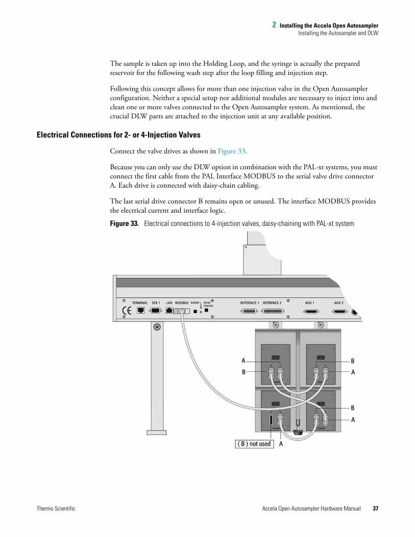
Connect the valve drives as shown in Figure 33.
Because you can only use the DLW option in combination with the PAL-xt systems, you must connect the first cable from the PAL Interface MODBUS to the serial valve drive connector A. Each drive is connected with daisy-chain cabling.
The last serial drive connector B remains open or unused. The interface MODBUS provides the electrical current and interface logic.
Figure 33. Electrical connections to 4-injection valves, daisy-chaining with PAL-xt system
2 Installing the Accela Open AutosamplerSystem Synchronization Connections
38 Accela Open Autosampler Hardware Manual Thermo Scientific
Installing the Power Supply for the Cooled Stack
The power supply for the cooled stack has a built-in control unit with display (P/N CH-952995).
To install the power supply
1. Locate the power supply and the AC power cable.
2. Set the power supply switch to OFF.
3. Connect the open end of the DC power cable from the stack/tray cooler to the power supply connector labeled, Peltier Thermostat.
4. Connect the female end of the AC power cable to the power supply, and then connect the male end to an AC power outlet.
5. Set the switch on the power supply to ON.
6. Observe the display to ensure that it reads the preset temperature of +10 °C.
System Synchronization ConnectionsThe system interconnect cables and adapter cables that synchronize the run signals for an LC or LC/MS system with an Accela Open Autosampler depend on the Accela pump model, the mass spectrometer model, and whether the LC system includes an Accela detector.
Table 5 lists the system interconnect and adapter cables that Thermo Fisher Scientific supplies with the Accela Open Autosampler or by special order.
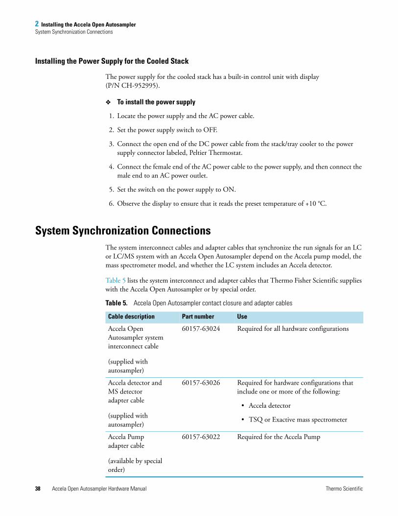
Table 5. Accela Open Autosampler contact closure and adapter cables
Cable description Part number Use
Accela Open Autosampler system interconnect cable
(supplied with autosampler)
60157-63024 Required for all hardware configurations
Accela detector and MS detector adapter cable
(supplied with autosampler)
60157-63026 Required for hardware configurations that include one or more of the following:
• Accela detector
• TSQ or Exactive mass spectrometer
Accela Pump adapter cable
(available by special order)
60157-63022 Required for the Accela Pump
2 Installing the Accela Open AutosamplerSystem Synchronization Connections
Thermo Scientific Accela Open Autosampler Hardware Manual 39
To connect the required cables listed in Table 5, follow these procedures as appropriate:
• Connecting the Accela Open Autosampler Interconnect Cable
• Connecting the Adapter Cable for an Accela Detector or TSQ Series MS Detector
• Connecting the Accela Pump Adapter Cable
Connecting the Accela Open Autosampler Interconnect Cable
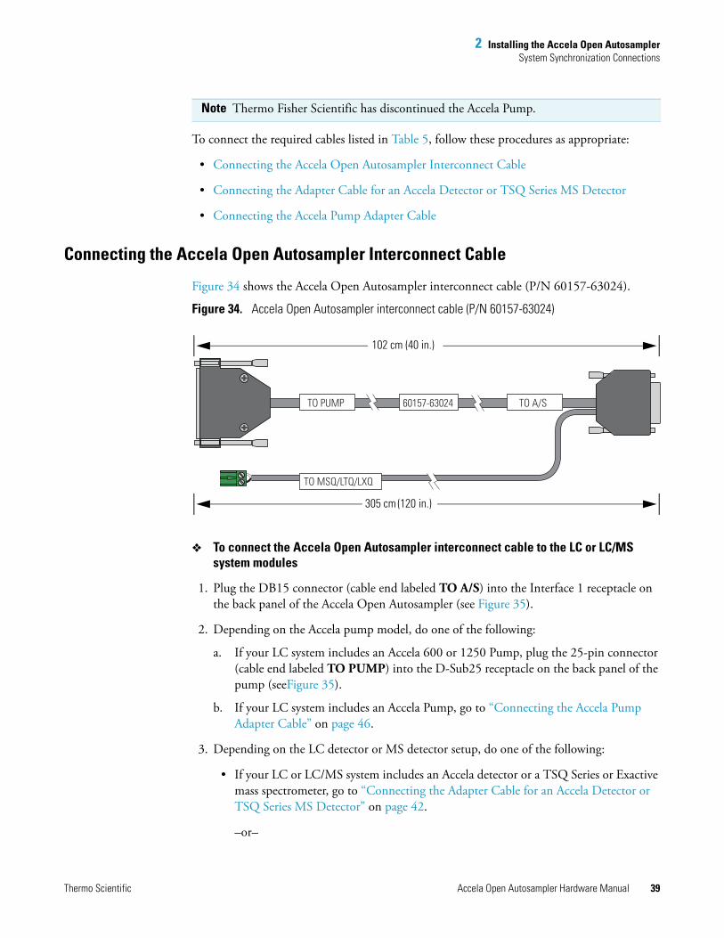
Figure 34 shows the Accela Open Autosampler interconnect cable (P/N 60157-63024).
Figure 34. Accela Open Autosampler interconnect cable (P/N 60157-63024)
To connect the Accela Open Autosampler interconnect cable to the LC or LC/MS system modules
1. Plug the DB15 connector (cable end labeled TO A/S) into the Interface 1 receptacle on the back panel of the Accela Open Autosampler (see Figure 35).
2. Depending on the Accela pump model, do one of the following:
a. If your LC system includes an Accela 600 or 1250 Pump, plug the 25-pin connector (cable end labeled TO PUMP) into the D-Sub25 receptacle on the back panel of the pump (seeFigure 35).
b. If your LC system includes an Accela Pump, go to “Connecting the Accela Pump Adapter Cable” on page 46.
3. Depending on the LC detector or MS detector setup, do one of the following:
• If your LC or LC/MS system includes an Accela detector or a TSQ Series or Exactive mass spectrometer, go to “Connecting the Adapter Cable for an Accela Detector or TSQ Series MS Detector” on page 42.
–or–
Note Thermo Fisher Scientific has discontinued the Accela Pump.
TO MSQ/LTQ/LXQ
TO PUMP 60157-63024 TO A/S
102 cm (40 in.)
305 cm (120 in.)
2 Installing the Accela Open AutosamplerSystem Synchronization Connections
40 Accela Open Autosampler Hardware Manual Thermo Scientific
• If your LC/MS system includes an MSQ Plus Mass Detector or an LTQ Series mass spectrometer, but does not include an Accela detector, go to step 4.
4. Connect the cable labeled TO MSQ/LTQ/LXQ to the mass spectrometer as follows:
• For the MSQ Plus Mass Detector, connect the cable to the User I/O Start In pins on the MS detector’s back panel (see Figure 35).
• For the LTQ Series mass spectrometer, connect the cable to the Peripheral Control Start In pins on the MS detector’s right panel (see Figure 35).
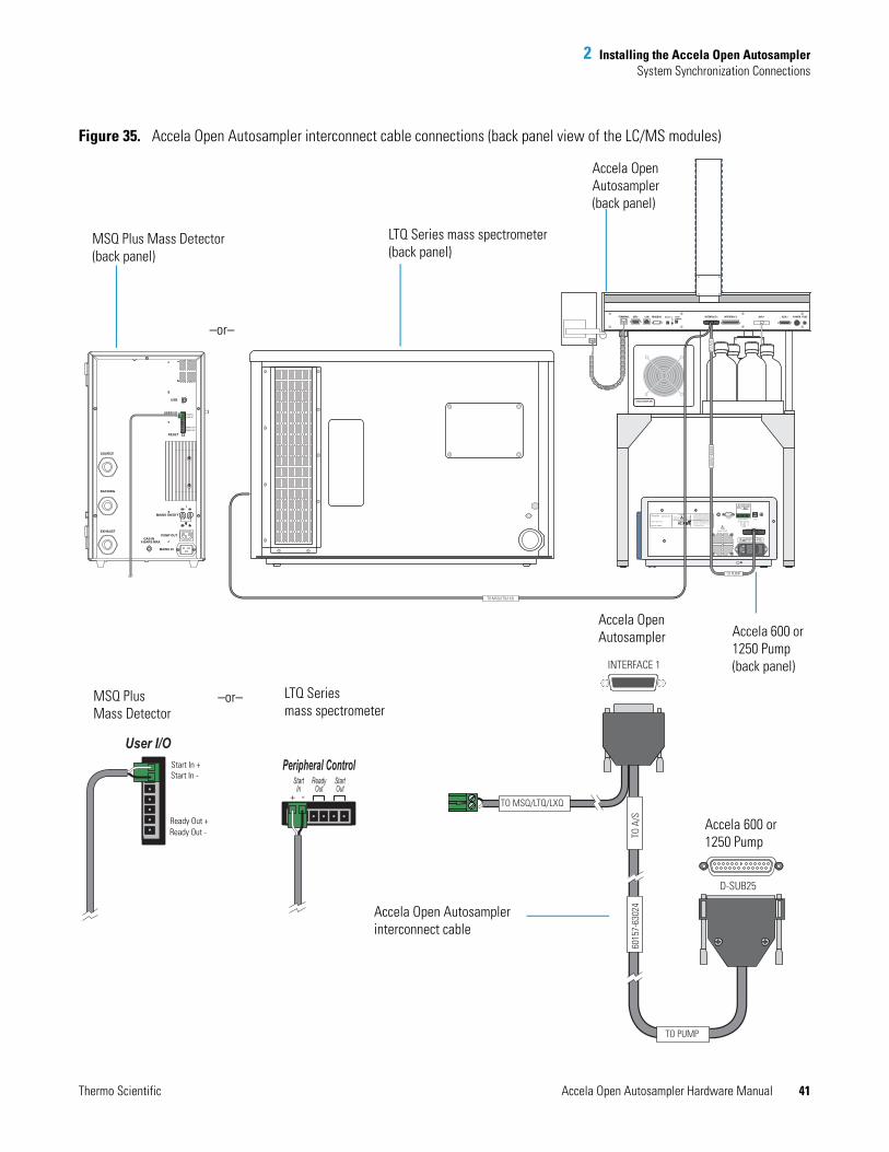
2 Installing the Accela Open AutosamplerSystem Synchronization Connections
Thermo Scientific Accela Open Autosampler Hardware Manual 41
Figure 35. Accela Open Autosampler interconnect cable connections (back panel view of the LC/MS modules)
AU
X
AUX 2 POWER FUSEAUX 1INTERFACE 2INTERFACE 1TERMINAL SER1 LAN MODBUS BUZZER WASHSTATION
LED
355 River Oaks ParkwaySan Jose, CA, U.S.A
This device complies with FCC Rules, Part 15.Operation is subject to the following conditions(1) This device may not cause harmful interference,and (2) This device must accept any interferencereceived, including interference that may causeundesired operation.This product is manufactured under, and coveredby, one or more of the following U.S. patents:
CAUTIONREFER ALL SERVICE
TO QUALIFIED
PERSONNEL ONLY.
DISCONNECT INPUT
POWER BEFORE
OPENING COVER.
RE
SE
RV
ED
RE
SE
RV
ED
GN
D
GN
D
INJE
CT H
OLD
PU
MP R
EA
DY
GR
AD
. STA
RT
5V
USB
D-SUB25
Model: 1250 Pump
Serial No: 925000
DO NOT COVER
RS232
5,653,876 6,248,157 B1
Futher patent pending
DO NOT USETOGETHER
WITHD-SUB25
!
!EP 2107241A2
1 2 3 4 5 6 7 8
EN61010 1
LINEFUSE
100V 115V 230V 50/60 HZ
T2.0A T1.0A 220VA
!
STACK COOLER DW
D-SUB25
INTERFACE 1
Peripheral ControlStart
InReady
OutStartOut
TO PUMP
TO A
/S60
157-
6302
4
TO MSQ/LTQ/LXQ
Start In +
Ready Out +
Start In -
Ready Out -
PUMP OUT
MAINS IN
MAINS ON/OFF
RESET
USER I/OSTART IN +START IN -
USB
READY OUT +
READY OUT -
GAS IN6 BARS MAX
SOURCE
BACKING
EXHAUST
User I/O
TO PUMP
6015
7-63
024
TO A
/S
TO MSQ/LTQ/LXQ
Accela Open Autosampler(back panel)
LTQ Series mass spectrometer (back panel)
MSQ Plus Mass Detector(back panel)
Accela 600 or 1250 Pump(back panel)
Accela Open Autosampler
Accela 600 or 1250 Pump
LTQ Series mass spectrometer
MSQ Plus Mass Detector
–or–
–or–
Accela Open Autosamplerinterconnect cable
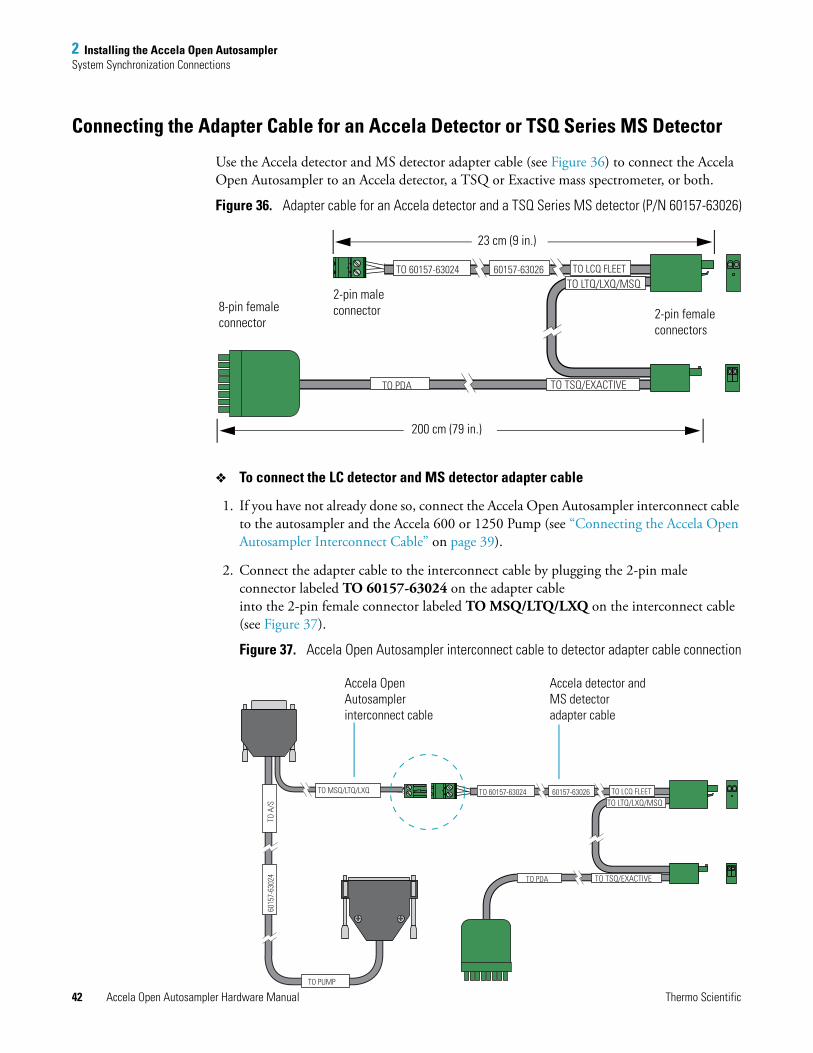
2 Installing the Accela Open AutosamplerSystem Synchronization Connections
42 Accela Open Autosampler Hardware Manual Thermo Scientific
Connecting the Adapter Cable for an Accela Detector or TSQ Series MS Detector
Use the Accela detector and MS detector adapter cable (see Figure 36) to connect the Accela Open Autosampler to an Accela detector, a TSQ or Exactive mass spectrometer, or both.
Figure 36. Adapter cable for an Accela detector and a TSQ Series MS detector (P/N 60157-63026)
To connect the LC detector and MS detector adapter cable
1. If you have not already done so, connect the Accela Open Autosampler interconnect cable to the autosampler and the Accela 600 or 1250 Pump (see “Connecting the Accela Open Autosampler Interconnect Cable” on page 39).
2. Connect the adapter cable to the interconnect cable by plugging the 2-pin male connector labeled TO 60157-63024 on the adapter cable into the 2-pin female connector labeled TO MSQ/LTQ/LXQ on the interconnect cable (see Figure 37).
Figure 37. Accela Open Autosampler interconnect cable to detector adapter cable connection
TO 60157-63024 60157-63026 TO LCQ FLEETTO LTQ/LXQ/MSQ
TO TSQ/EXACTIVETO PDA
2-pin male connector 2-pin female
connectors
8-pin female connector
23 cm (9 in.)
200 cm (79 in.)
TO 60157-63024 60157-63026 TO LCQ FLEETTO LTQ/LXQ/MSQ
TO TSQ/EXACTIVETO PDA
TO MSQ/LTQ/LXQ
TO PUMP
6015
7-63
024
TO A
/S
Accela detector and MS detector adapter cable
Accela Open Autosamplerinterconnect cable
2 Installing the Accela Open AutosamplerSystem Synchronization Connections
Thermo Scientific Accela Open Autosampler Hardware Manual 43
3. Using the adapter cable connectors, make the appropriate connections to an Accela detector, a Thermo Scientific mass spectrometer, or both as follows:
• For an Accela detector (UV/Vis, PDA, or RI), connect the 8-pin connector attached to the cable labeled TO PDA to pins 1 through 8 on the detector’s back panel.
• For an MSQ Plus Mass Detector, connect the 2-pin connector attached to the cable labeled TO LTQ/LXQ/MSQ to the Start In pins on the mass spectrometer’s back panel.
• For an LTQ Series mass spectrometer, connect the 2-pin connector attached to the cables labeled TO LTQ/LXQ/MSQ and TO LCQ FLEET to the Start In pins on the right side of the mass spectrometer.
• For a TSQ or Exactive mass spectrometer, connect the cable labeled TSQ/EXACTIVE to the Start In pins on the right side of the mass spectrometer.
Figure 38 and Figure 39 show the contact closure connections for a standalone Accela LC system and an LC/MS system, respectively.
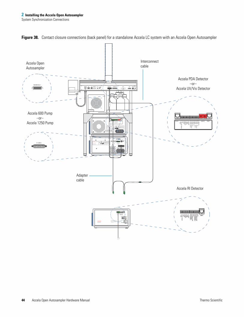
2 Installing the Accela Open AutosamplerSystem Synchronization Connections
44 Accela Open Autosampler Hardware Manual Thermo Scientific
Figure 38. Contact closure connections (back panel) for a standalone Accela LC system with an Accela Open Autosampler
ENET1 2 3 4 5 6 7 8 9 10 11 12 13 14 15 16
PURG
EG
ND
ZEROREA
DY
RUN
NC
+5V @ 150m
AG
ND
NC
CHA
SSIS GN
DIN
TEGRATO
R --IN
TEGRATO
R +N
CCH
ASSIS G
ND
RECORD
ER --RECO
RDER +
355 River Oaks ParkwaySan Jose, CA 95134 U.S.A.
This device complies with Part 15 of the FCC Rules.Operation is subject to the following two conditions:1) This device may not cause harmful interference, and2) This device must accept any interference received, including interference that may cause undesired operation.
61010 - 1
CAUTIONDisconnect Input Power Before Opening Cover
Service by Qualified Personnel
220V T1.6AL 250V 100VA110V T3.15AL 250V 100VA
FUSE
110V/220V 50/60HZLINE
AU
X
AUX 2 POWER FUSEAUX 1INTERFACE 2INTERFACE 1TERMINAL SER1 LAN MODBUS BUZZER WASHSTATION
LED
USE ONLY WITH250 V FUSES
DISCONNECT POWERBEFORE REPLACING FUSES
This device complies with FCC Rules, Part 15.Operation is subject to the following conditions(1) This device may not cause harmful interference,and (2) This device must accept any interferencereceived, including interference that may causeundesired operation.
355 River Oaks ParkwaySan Jose, CA 95134, U.S.A
Model:Serial No:Part No:Option/Firmware
Accela PDA 80 Hz Detector940XXX60057-601415cm Lightpipe / 3.00
This product is manufactured under, and coveredby, one or more of the following U.S. patents:
REFER ALL SERVICE
TO QUALIFIED
PERSONNEL ONLY
DISCONNECT INPUT
POWER BEFORE
OPENING COVER.
5, 608, 51761010 1
CAUTION
LINEFUSE
100V 115V 230V 50/60 HZ
T3.15A/250V T1.6A/250V 100VA
GN
D B
CH
B - 1V
CH
B - 100m
VC
HB
- 10mV
GN
D A
CH
A - 1VC
HA - 100m
VC
HA - 10m
V
1 2 3 4 5 6 7 8 ENETRS232 UNIT ID9 10 11 12 13 14 15 16
EV
EN
TG
ND
ZER
OR
EA
DY
RU
NN
C+5V
@ 150m
AG
ND
12 3
45
6
78
90
1
2 3 45
6
78
90
355 River Oaks ParkwaySan Jose, CA, U.S.A
This device complies with FCC Rules, Part 15.Operation is subject to the following conditions(1) This device may not cause harmful interference,and (2) This device must accept any interferencereceived, including interference that may causeundesired operation.This product is manufactured under, and coveredby, one or more of the following U.S. patents:
CAUTIONREFER ALL SERVICE
TO QUALIFIED
PERSONNEL ONLY.
DISCONNECT INPUT
POWER BEFORE
OPENING COVER.
RE
SE
RV
ED
RE
SE
RV
ED
GN
D
GN
D
INJE
CT H
OLD
PU
MP R
EA
DY
GR
AD
. STA
RT
5V
USB
D-SUB25
Model: 1250 Pump
Serial No: 925000
DO NOT COVER
RS232
5,653,876 6,248,157 B1
Futher patent pending
DO NOT USETOGETHER
WITHD-SUB25
!
!EP 2107241A2
1 2 3 4 5 6 7 8
EN61010 1
LINEFUSE
100V 115V 230V 50/60 HZ
T2.0A T1.0A 220VA
!
STACK COOLER DWTO
A/S
TO PUMP
TO MSQ/LTQ/LXQ
6015
7-63
024
TO L
CQ F
LEET
TO LTQ/
LXQ/
MSQ
TO 60157-6302460157-63026
TO TSQ
/EXA
CTIV
ETO
PDA
ENET
PURG
EG
ND
ZEROREA
DY
RUN
NC
+5V @ 150m
AG
ND
NC
CHA
SSIS GN
DIN
TEGRATO
R --IN
TEGRATO
R +N
CCH
ASSIS G
ND
RECORD
ER --RECO
RDER +
1 2 3 4 5 6 7 8 9 10 11 12 13 14 15 16
1
2 3
45
67
8
1
2 3
45
678
INTERFACE 1
D-SUB25
Accela 600 Pump–or–
Accela 1250 Pump
Accela RI Detector
Accela PDA Detector–or–
Accela UV/Vis Detector
Accela Open Autosampler
Interconnect cable
Adapter cable
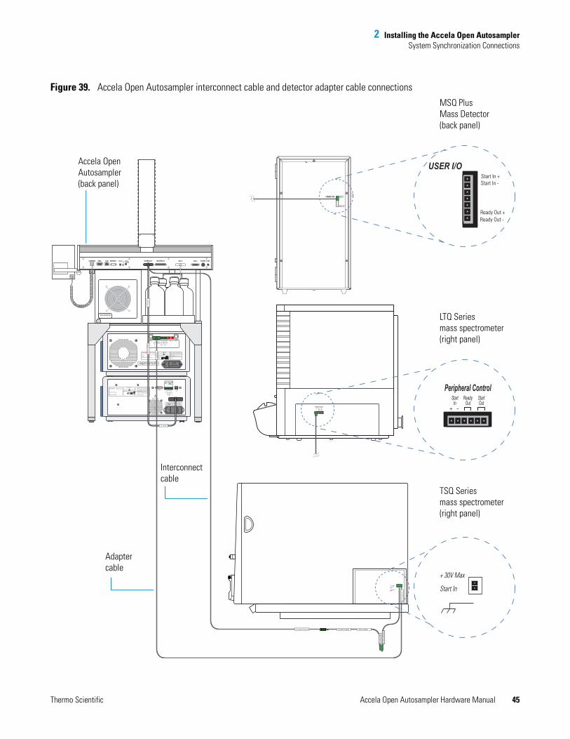
2 Installing the Accela Open AutosamplerSystem Synchronization Connections
Thermo Scientific Accela Open Autosampler Hardware Manual 45
Figure 39. Accela Open Autosampler interconnect cable and detector adapter cable connections
AU
X
AUX 2 POWER FUSEAUX 1INTERFACE 2INTERFACE 1TERMINAL SER1 LAN MODBUS BUZZER WASHSTATION
LED
USE ONLY WITH250 V FUSES
DISCONNECT POWERBEFORE REPLACING FUSES
This device complies with FCC Rules, Part 15.Operation is subject to the following conditions(1) This device may not cause harmful interference,and (2) This device must accept any interferencereceived, including interference that may causeundesired operation.
355 River Oaks ParkwaySan Jose, CA 95134, U.S.A
Model:Serial No:Part No:Option/Firmware
Accela PDA 80 Hz Detector940XXX60057-601415cm Lightpipe / 3.00
This product is manufactured under, and coveredby, one or more of the following U.S. patents:
REFER ALL SERVICE
TO QUALIFIED
PERSONNEL ONLY
DISCONNECT INPUT
POWER BEFORE
OPENING COVER.
5, 608, 51761010 1
CAUTION
LINEFUSE
100V 115V 230V 50/60 HZ
T3.15A/250V T1.6A/250V 100VA
GN
D B
CH
B - 1V
CH
B - 100m
VC
HB
- 10mV
GN
D A
CH
A - 1VC
HA - 100m
VC
HA - 10m
V
1 2 3 4 5 6 7 8 ENETRS232 UNIT ID9 10 11 12 13 14 15 16
EV
EN
TG
ND
ZER
OR
EA
DY
RU
NN
C+5V
@ 150m
AG
ND
1
2 3
45
6
78
90
1
2 3 45
678
90
355 River Oaks ParkwaySan Jose, CA, U.S.A
This device complies with FCC Rules, Part 15.Operation is subject to the following conditions(1) This device may not cause harmful interference,and (2) This device must accept any interferencereceived, including interference that may causeundesired operation.This product is manufactured under, and coveredby, one or more of the following U.S. patents:
CAUTIONREFER ALL SERVICE
TO QUALIFIED
PERSONNEL ONLY.
DISCONNECT INPUT
POWER BEFORE
OPENING COVER.
RE
SE
RV
ED
RE
SE
RV
ED
GN
D
GN
D
INJE
CT H
OLD
PU
MP R
EA
DY
GR
AD
. STA
RT
5V
USB
D-SUB25
Model: 1250 Pump
Serial No: 925000
DO NOT COVER
RS232
5,653,876 6,248,157 B1
Futher patent pending
DO NOT USETOGETHER
WITHD-SUB25
!
!EP 2107241A2
1 2 3 4 5 6 7 8
EN61010 1
LINEFUSE
100V 115V 230V 50/60 HZ
T2.0A T1.0A 220VA
!
STACK COOLER DW
TO A
/S
TO PUMP
6015
7-63
024
TO MSQ/LTQ/LXQ
+ 30V Max
Start In
USER I/O START IN +START IN -
READY OUT +READY OUT -
Start In +
Ready Out +
Start In -
Ready Out -
USER I/O
Peripheral ControlStart
InReady
OutStartOut
+ 30V MaxStart In
TO 60157-63024
TO TSQ
/EXA
CTIV
E
TO L
CQ F
LEET
TO LTQ/
LXQ/
MSQ
TO P
DA
60157-63026
Peripheral ControlStart
InReady
OutStartOut
Accela Open Autosampler(back panel)
Interconnectcable
Adapter cable
MSQ PlusMass Detector (back panel)
LTQ Series mass spectrometer(right panel)
TSQ Series mass spectrometer(right panel)
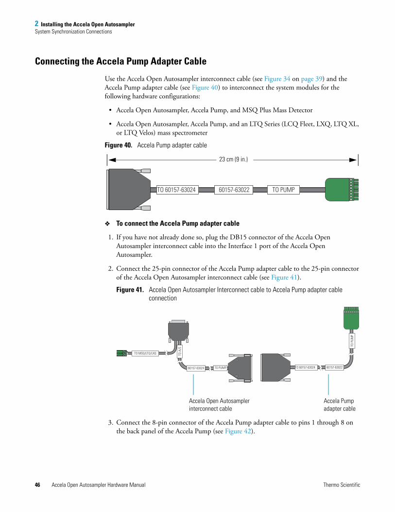
2 Installing the Accela Open AutosamplerSystem Synchronization Connections
46 Accela Open Autosampler Hardware Manual Thermo Scientific
Connecting the Accela Pump Adapter Cable
Use the Accela Open Autosampler interconnect cable (see Figure 34 on page 39) and the Accela Pump adapter cable (see Figure 40) to interconnect the system modules for the following hardware configurations:
• Accela Open Autosampler, Accela Pump, and MSQ Plus Mass Detector
• Accela Open Autosampler, Accela Pump, and an LTQ Series (LCQ Fleet, LXQ, LTQ XL, or LTQ Velos) mass spectrometer
Figure 40. Accela Pump adapter cable
To connect the Accela Pump adapter cable
1. If you have not already done so, plug the DB15 connector of the Accela Open Autosampler interconnect cable into the Interface 1 port of the Accela Open Autosampler.
2. Connect the 25-pin connector of the Accela Pump adapter cable to the 25-pin connector of the Accela Open Autosampler interconnect cable (see Figure 41).
Figure 41. Accela Open Autosampler Interconnect cable to Accela Pump adapter cable connection
3. Connect the 8-pin connector of the Accela Pump adapter cable to pins 1 through 8 on the back panel of the Accela Pump (see Figure 42).
TO PUMP60157-63022TO 60157-63024
23 cm (9 in.)
TO P
UMP
TO 60157-63024 60157-63022
TO A
/STO
A/S
TO A
/STO
A/S
TO A
/STO
A/S
TO A
/STO
A/S
60157-63024
TO MSQ/LTQ/LXQ
TO PUMP
Accela Open Autosamplerinterconnect cable
Accela Pumpadapter cable

2 Installing the Accela Open AutosamplerSystem Synchronization Connections
Thermo Scientific Accela Open Autosampler Hardware Manual 47
4. Connect the 2-pin connector of the Accela Open Autosampler interconnect cable to the mass spectrometer (see “Connecting the Accela Open Autosampler Interconnect Cable” on page 39).
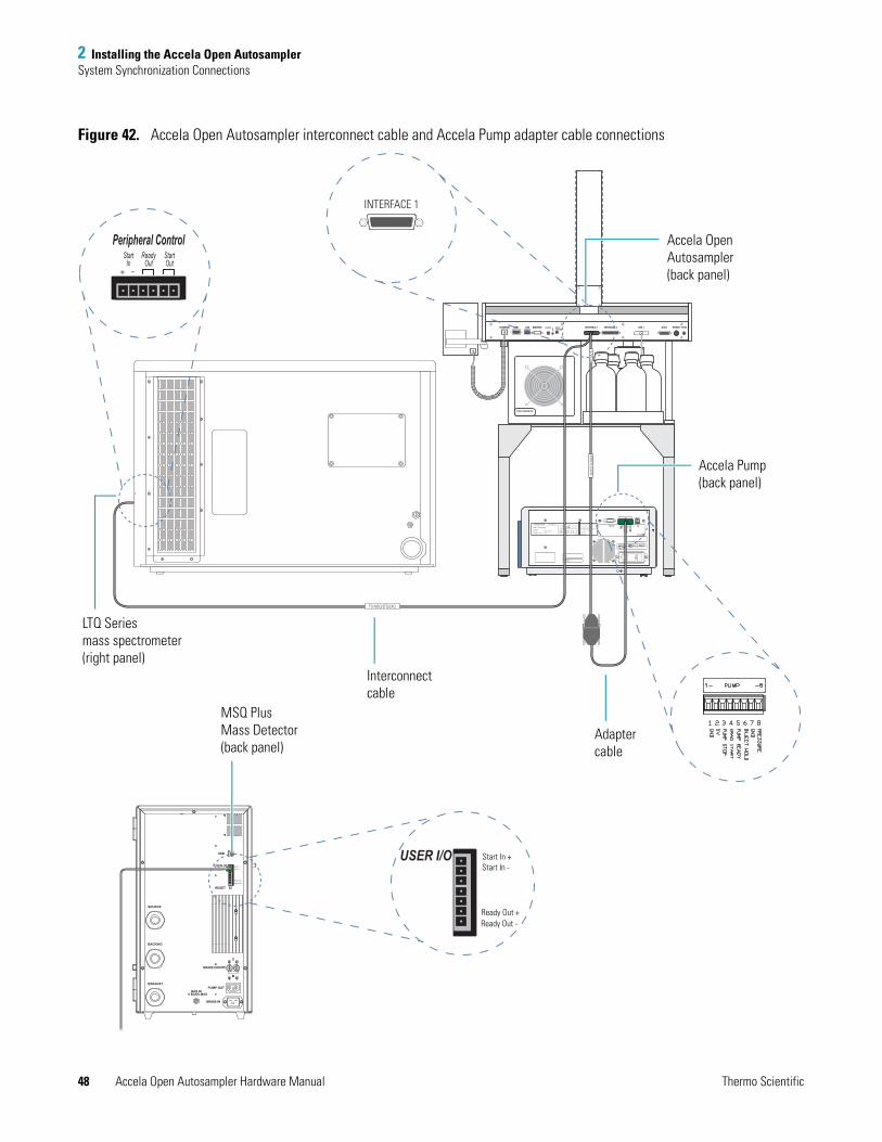
2 Installing the Accela Open AutosamplerSystem Synchronization Connections
48 Accela Open Autosampler Hardware Manual Thermo Scientific
Figure 42. Accela Open Autosampler interconnect cable and Accela Pump adapter cable connections
PUMP OUT
MAINS IN
MAINS ON/OFF
RESET
USB
GAS IN6 BARS MAX
SOURCE
BACKING
EXHAUST
Start In +
Ready Out +
Start In -
Ready Out -
USER I/OStart In +
Ready Out +
Start In -
Ready Out -
USER I/O
AU
X
AUX 2 POWER FUSEAUX 1INTERFACE 2INTERFACE 1TERMINAL SER1 LAN MODBUS BUZZER WASHSTATION
LED
355 River Oaks ParkwaySan Jose, CA, U.S.A
This device complies with FCC Rules, Part 15.Operation is subject to the following conditions(1) This device may not cause harmful interference,and (2) This device must accept any interferencereceived, including interference that may causeundesired operation.This product is manufactured under, and coveredby, one or more of the following U.S. patents:
CAUTIONREFER ALL SERVICE
TO QUALIFIED
PERSONNEL ONLY.
DISCONNECT INPUT
POWER BEFORE
OPENING COVER.
RE
SE
RV
ED
RE
SE
RV
ED
GN
D
GN
D
INJE
CT H
OLD
PU
MP R
EA
DY
GR
AD
. STA
RT
5V
USB
D-SUB25
Model: 1250 Pump
Serial No: 925000
DO NOT COVER
RS232
5,653,876 6,248,157 B1
Futher patent pending
DO NOT USETOGETHER
WITHD-SUB25
!
!EP 2107241A2
1 2 3 4 5 6 7 8
EN61010 1
LINEFUSE
100V 115V 230V 50/60 HZ
T2.0A T1.0A 220VA
!
STACK COOLER DW
Accela Pump
60057-6001012472
5,653,8766,248,157B1
61010 - 1
Model:
Serial No:
Part No:
Options/Firmware:
This product is manufactured under, and covered by,one or more of the following U.S. patents:
355 River Oaks ParkwaySan Jose, CA 95134 U.S.A.
This device complies with FCC Rules, Part 15. Operation is subject to the following two conditions: (1) This device may not cause harmful interference, and (2) This device must accept any interference received, including interference that may cause undesired operation.
DISCONNECT INPUT POWER BEFORE OPENING COVER.
REFER ALL SERVICETO QUALIFIEDPERSONNEL ONLY.
CAUTION
INTERFACE 1
Peripheral ControlStart
InReady
OutStartOut
TO MSQ/LTQ/LXQ
TO A
/S60
157-
6302
4
Accela Open Autosampler(back panel)
MSQ PlusMass Detector (back panel)
LTQ Series mass spectrometer(right panel)
Accela Pump(back panel)
Interconnectcable
Adapter cable
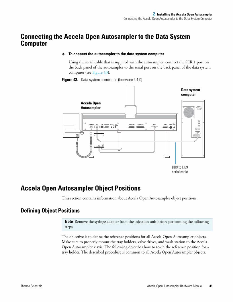
2 Installing the Accela Open AutosamplerConnecting the Accela Open Autosampler to the Data System Computer
Thermo Scientific Accela Open Autosampler Hardware Manual 49
Connecting the Accela Open Autosampler to the Data System Computer
To connect the autosampler to the data system computer
Using the serial cable that is supplied with the autosampler, connect the SER 1 port on the back panel of the autosampler to the serial port on the back panel of the data system computer (see Figure 43).
Figure 43. Data system connection (firmware 4.1.0)
Accela Open Autosampler Object PositionsThis section contains information about Accela Open Autosampler object positions.
Defining Object Positions
The objective is to define the reference positions for all Accela Open Autosampler objects. Make sure to properly mount the tray holders, valve drives, and wash station to the Accela Open Autosampler x axis. The following describes how to teach the reference position for a tray holder. The described procedure is common to all Accela Open Autosampler objects.
AUX 2 POWER FUSEAUX 1INTERFACE 2INTERFACE 1TERMINAL SER1 LAN MODBUS BUZZER WASHSTATION
LED
Accela Open Autosampler
Data system computer
DB9 to DB9 serial cable
Note Remove the syringe adapter from the injection unit before performing the following steps.
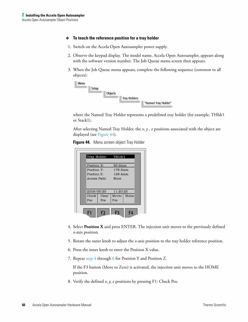
2 Installing the Accela Open AutosamplerAccela Open Autosampler Object Positions
50 Accela Open Autosampler Hardware Manual Thermo Scientific
To teach the reference position for a tray holder
1. Switch on the Accela Open Autosampler power supply.
2. Observe the keypad display. The model name, Accela Open Autosampler, appears along with the software version number. The Job Queue menu screen then appears.
3. When the Job Queue menu appears, complete the following sequence (common to all objects):
where the Named Tray Holder represents a predefined tray holder (for example, THldr1 or Stack1).
After selecting Named Tray Holder, the x, y , z positions associated with the object are displayed (see Figure 44).
Figure 44. Menu screen object Tray Holder
4. Select Position X and press ENTER. The injection unit moves to the previously defined x-axis position.
5. Rotate the outer knob to adjust the x-axis position to the tray holder reference position.
6. Press the inner knob to enter the Position X value.
7. Repeat step 4 through 6 for Position Y and Position Z.
If the F3 button (Move to Zero) is activated, the injection unit moves to the HOME position.
8. Verify the defined x, y, z positions by pressing F1: Check Pos.
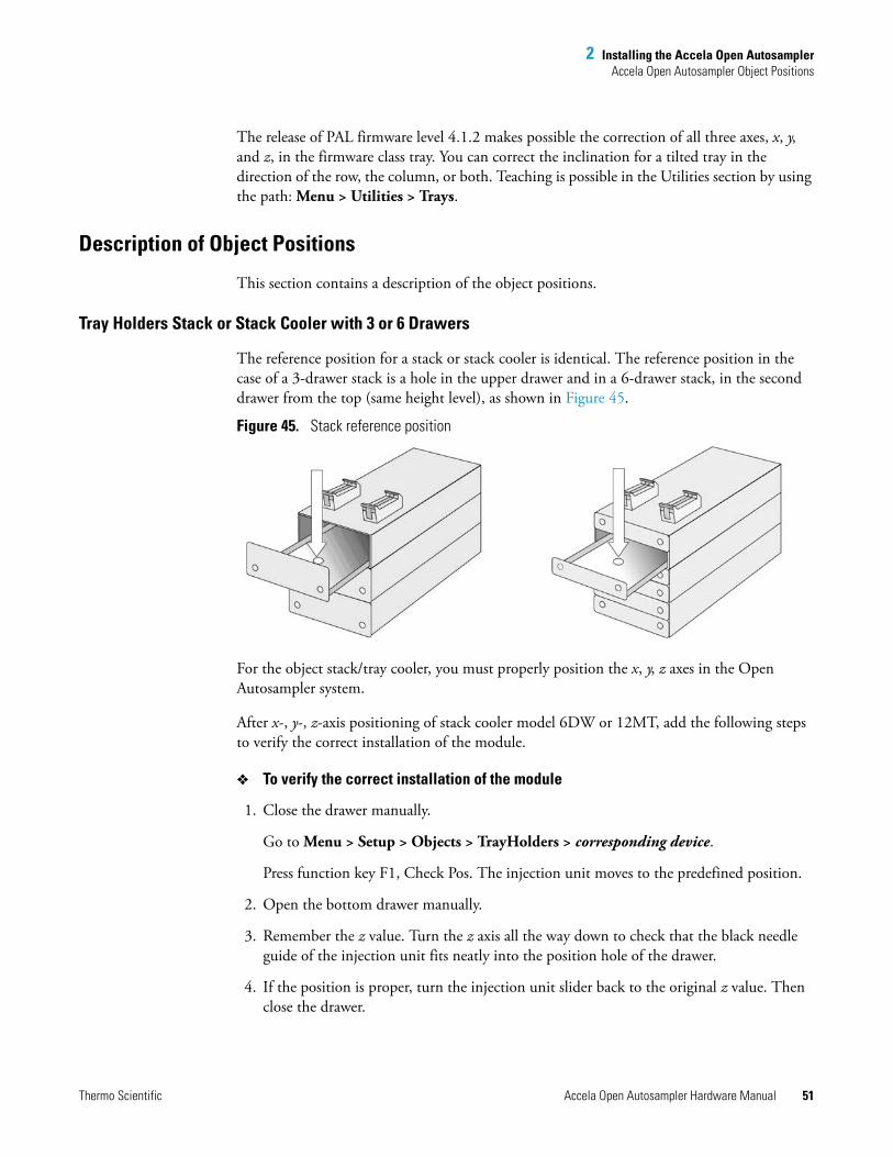
2 Installing the Accela Open AutosamplerAccela Open Autosampler Object Positions
Thermo Scientific Accela Open Autosampler Hardware Manual 51
The release of PAL firmware level 4.1.2 makes possible the correction of all three axes, x, y, and z, in the firmware class tray. You can correct the inclination for a tilted tray in the direction of the row, the column, or both. Teaching is possible in the Utilities section by using the path: Menu > Utilities > Trays.
Description of Object Positions
This section contains a description of the object positions.
Tray Holders Stack or Stack Cooler with 3 or 6 Drawers
The reference position for a stack or stack cooler is identical. The reference position in the case of a 3-drawer stack is a hole in the upper drawer and in a 6-drawer stack, in the second drawer from the top (same height level), as shown in Figure 45.
Figure 45. Stack reference position
For the object stack/tray cooler, you must properly position the x, y, z axes in the Open Autosampler system.
After x-, y-, z-axis positioning of stack cooler model 6DW or 12MT, add the following steps to verify the correct installation of the module.
To verify the correct installation of the module
1. Close the drawer manually.
Go to Menu > Setup > Objects > TrayHolders > corresponding device.
Press function key F1, Check Pos. The injection unit moves to the predefined position.
2. Open the bottom drawer manually.
3. Remember the z value. Turn the z axis all the way down to check that the black needle guide of the injection unit fits neatly into the position hole of the drawer.
4. If the position is proper, turn the injection unit slider back to the original z value. Then close the drawer.
2 Installing the Accela Open AutosamplerAccela Open Autosampler Object Positions
52 Accela Open Autosampler Hardware Manual Thermo Scientific
5. If the position is off by one or two millimeters, compensate for any discrepancy in the x, y position seen between the upper and lower drawer.
6. If the position is off by more than one or two millimeters, check the bracket attachment of the module to the x axis carefully. If in doubt, loosen the claws again and reposition the unit on the x axis.
If this action is not successful, check the x- to y-axis angle and the y- to z-axis angle. If one of these angles is not 90°, make corrections.
Ensure also that the y axis runs parallel to the open drawer. If this is not the case, the bracket alignment is probably out of square.
Trays
Generally, you do not need to teach a tray position. The tray holder has a teaching position, as described earlier. The firmware assigns a tray to the tray holder. The numbers (values) for the relevant items are stored in the firmware object tray. To complete the combination of a tray holder and a tray, you must assign the corresponding tray type to the tray.
The tray type contains the geometric data for the tray and information, such as how many samples are in a row and a column in the tray. A tray type defines the pattern and sampling sequence of the sample location within a tray.
Again, the tray is physically placed in the tray holder, the firmware assigns the tray to the tray holder and the tray type to the tray. This is routine procedure as long as no special circumstances intervene, such as customized trays or tray types.
PAL Firmware level 4.1.2 or later now makes a correction possible if the tray surface is not exactly horizontal and planar but is inclined in one or more axes. The ability to make the correction is standard at level 4.1.x. A dialog box opens the moment the tray has been checked out at the corners to verify vial positions and heights. The following sections explain how to correct a possible inclination.
Note The y axis tolerance for the teaching point is limited to 129.4 mm (5.09 in.).
When defining the position of the stack cooler, make sure you stay within this tolerance with the reference point at the top drawer.
CAUTION Do not use vials without a sealing cap or a microtiter- or deepwell-plate without a plate seal. Vapor phase from organic solvents can be hazardous and flammable. Acidic vapor phase can cause corrosion to critical mechanical parts.
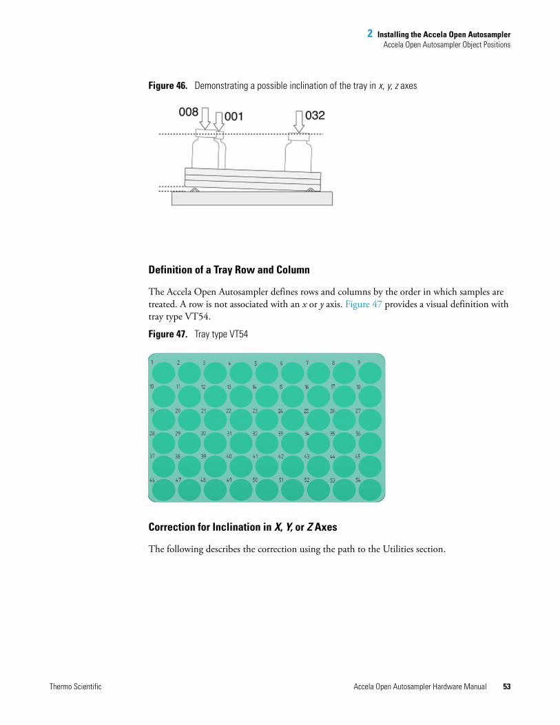
2 Installing the Accela Open AutosamplerAccela Open Autosampler Object Positions
Thermo Scientific Accela Open Autosampler Hardware Manual 53
Figure 46. Demonstrating a possible inclination of the tray in x, y, z axes
Definition of a Tray Row and Column
The Accela Open Autosampler defines rows and columns by the order in which samples are treated. A row is not associated with an x or y axis. Figure 47 provides a visual definition with tray type VT54.
Figure 47. Tray type VT54
Correction for Inclination in X, Y, or Z Axes
The following describes the correction using the path to the Utilities section.
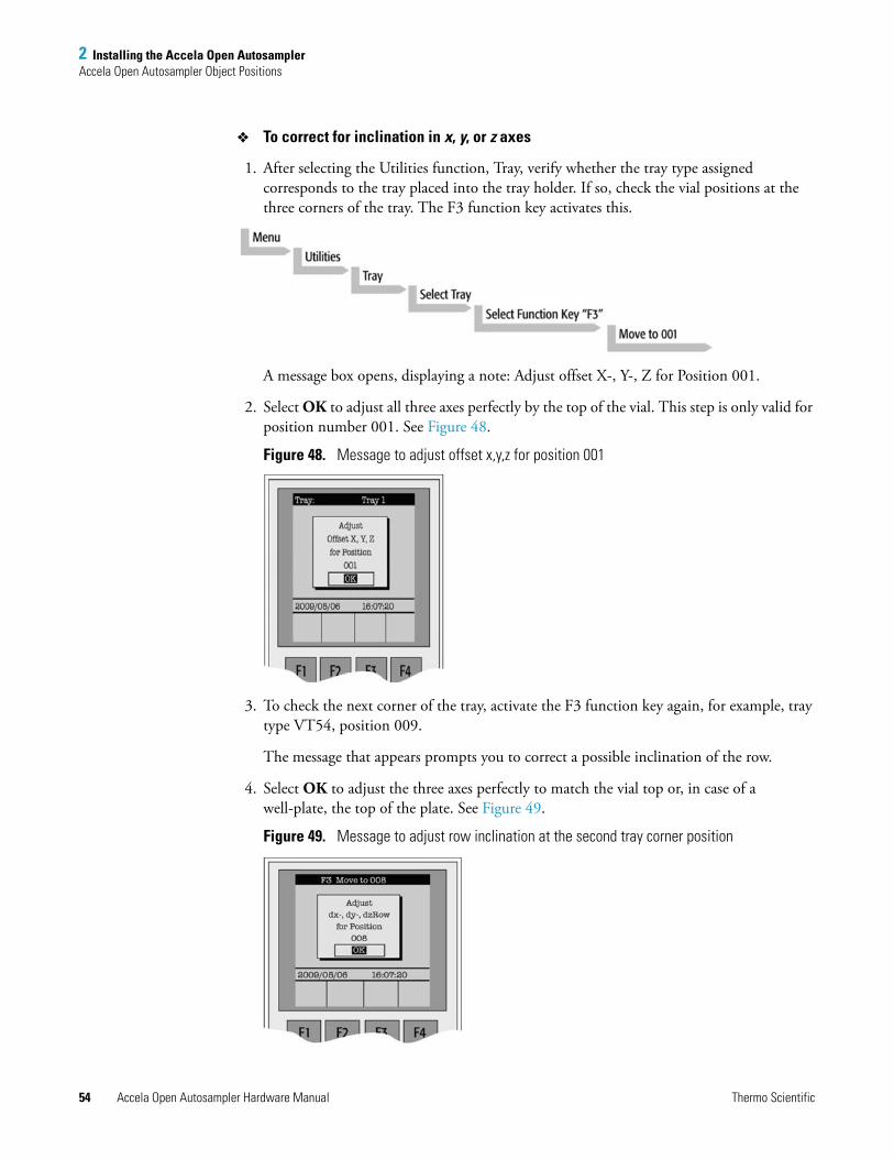
2 Installing the Accela Open AutosamplerAccela Open Autosampler Object Positions
54 Accela Open Autosampler Hardware Manual Thermo Scientific
To correct for inclination in x, y, or z axes
1. After selecting the Utilities function, Tray, verify whether the tray type assigned corresponds to the tray placed into the tray holder. If so, check the vial positions at the three corners of the tray. The F3 function key activates this.
A message box opens, displaying a note: Adjust offset X-, Y-, Z for Position 001.
2. Select OK to adjust all three axes perfectly by the top of the vial. This step is only valid for position number 001. See Figure 48.
Figure 48. Message to adjust offset x,y,z for position 001
3. To check the next corner of the tray, activate the F3 function key again, for example, tray type VT54, position 009.
The message that appears prompts you to correct a possible inclination of the row.
4. Select OK to adjust the three axes perfectly to match the vial top or, in case of a well-plate, the top of the plate. See Figure 49.
Figure 49. Message to adjust row inclination at the second tray corner position
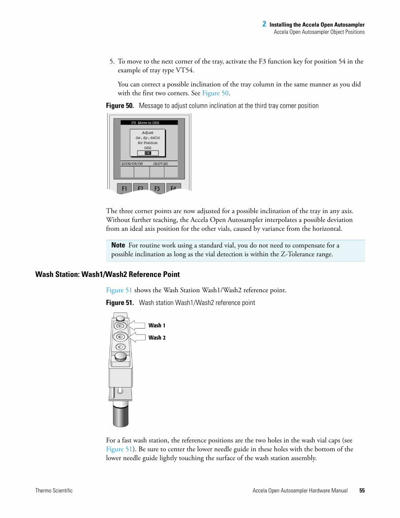
2 Installing the Accela Open AutosamplerAccela Open Autosampler Object Positions
Thermo Scientific Accela Open Autosampler Hardware Manual 55
5. To move to the next corner of the tray, activate the F3 function key for position 54 in the example of tray type VT54.
You can correct a possible inclination of the tray column in the same manner as you did with the first two corners. See Figure 50.
Figure 50. Message to adjust column inclination at the third tray corner position
The three corner points are now adjusted for a possible inclination of the tray in any axis. Without further teaching, the Accela Open Autosampler interpolates a possible deviation from an ideal axis position for the other vials, caused by variance from the horizontal.
Wash Station: Wash1/Wash2 Reference Point
Figure 51 shows the Wash Station Wash1/Wash2 reference point.
Figure 51. Wash station Wash1/Wash2 reference point
For a fast wash station, the reference positions are the two holes in the wash vial caps (see Figure 51). Be sure to center the lower needle guide in these holes with the bottom of the lower needle guide lightly touching the surface of the wash station assembly.
Note For routine work using a standard vial, you do not need to compensate for a possible inclination as long as the vial detection is within the Z-Tolerance range.
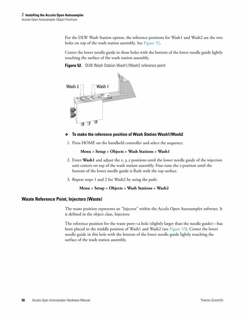
2 Installing the Accela Open AutosamplerAccela Open Autosampler Object Positions
56 Accela Open Autosampler Hardware Manual Thermo Scientific
For the DLW Wash Station option, the reference positions for Wash1 and Wash2 are the two holes on top of the wash station assembly. See Figure 52.
Center the lower needle guide in these holes with the bottom of the lower needle guide lightly touching the surface of the wash station assembly.
Figure 52. DLW Wash Station Wash1/Wash2 reference point
To make the reference position of Wash Station Wash1/Wash2
1. Press HOME on the handheld controller and select the sequence:
Menu > Setup > Objects > Wash Stations > Wash1
2. Enter Wash1 and adjust the x, y, z positions until the lower needle guide of the injection unit centers on top of the wash station assembly. Fine-tune the z position until the bottom of the lower needle guide is flush with the top surface.
3. Repeat steps 1 and 2 for Wash2 by using the path:
Menu > Setup > Objects > Wash Stations > Wash2
Waste Reference Point, Injectors (Waste)
The waste position represents an "Injector" within the Accela Open Autosampler software. It is defined in the object class, Injectors.
The reference position for the waste port—a hole (slightly larger than the needle guide)—has been placed in the middle position of Wash1 and Wash2 (see Figure 53). Center the lower needle guide in this hole with the bottom of the lower needle guide lightly touching the surface of the wash station assembly.
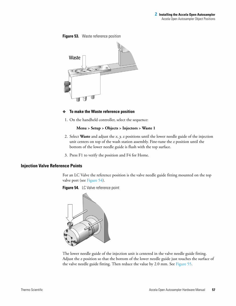
2 Installing the Accela Open AutosamplerAccela Open Autosampler Object Positions
Thermo Scientific Accela Open Autosampler Hardware Manual 57
Figure 53. Waste reference position
To make the Waste reference position
1. On the handheld controller, select the sequence:
Menu > Setup > Objects > Injectors > Waste 1
2. Select Waste and adjust the x, y, z positions until the lower needle guide of the injection unit centers on top of the wash station assembly. Fine-tune the z position until the bottom of the lower needle guide is flush with the top surface.
3. Press F1 to verify the position and F4 for Home.
Injection Valve Reference Points
For an LC Valve the reference position is the valve needle guide fitting mounted on the top valve port (see Figure 54).
Figure 54. LC Valve reference point
The lower needle guide of the injection unit is centered in the valve needle guide fitting. Adjust the z position so that the bottom of the lower needle guide just touches the surface of the valve needle guide fitting. Then reduce the value by 2.0 mm. See Figure 55.
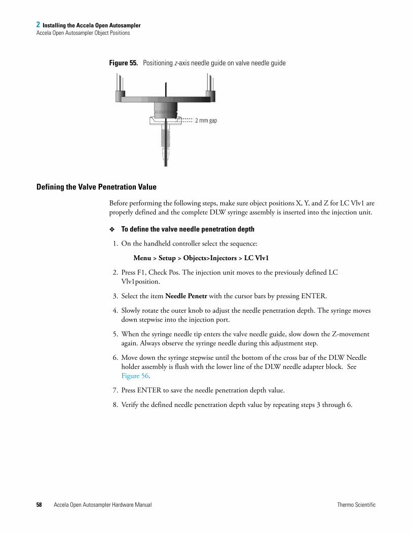
2 Installing the Accela Open AutosamplerAccela Open Autosampler Object Positions
58 Accela Open Autosampler Hardware Manual Thermo Scientific
Figure 55. Positioning z-axis needle guide on valve needle guide
Defining the Valve Penetration Value
Before performing the following steps, make sure object positions X, Y, and Z for LC Vlv1 are properly defined and the complete DLW syringe assembly is inserted into the injection unit.
To define the valve needle penetration depth
1. On the handheld controller select the sequence:
Menu > Setup > Objects>Injectors > LC Vlv1
2. Press F1, Check Pos. The injection unit moves to the previously defined LC Vlv1position.
3. Select the item Needle Penetr with the cursor bars by pressing ENTER.
4. Slowly rotate the outer knob to adjust the needle penetration depth. The syringe moves down stepwise into the injection port.
5. When the syringe needle tip enters the valve needle guide, slow down the Z-movement again. Always observe the syringe needle during this adjustment step.
6. Move down the syringe stepwise until the bottom of the cross bar of the DLW Needle holder assembly is flush with the lower line of the DLW needle adapter block. See Figure 56.
7. Press ENTER to save the needle penetration depth value.
8. Verify the defined needle penetration depth value by repeating steps 3 through 6.
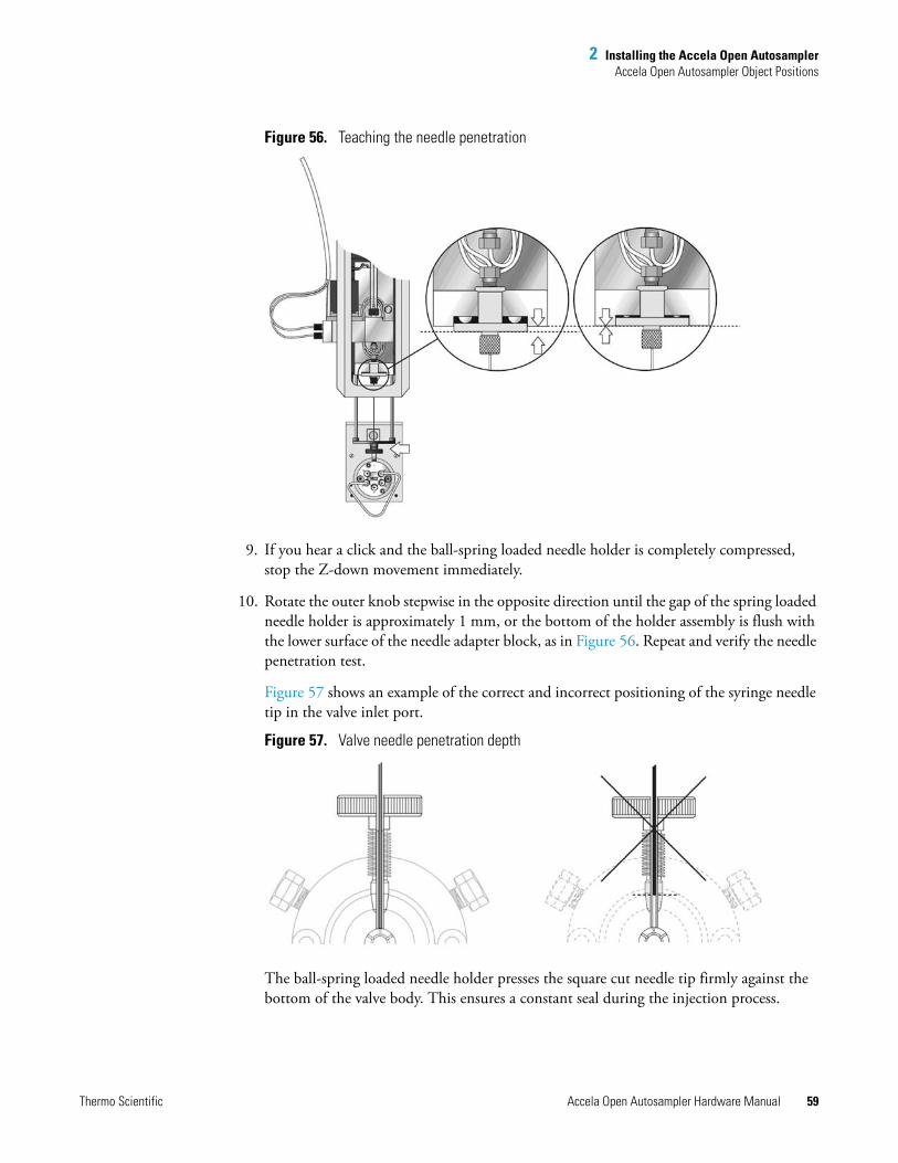
2 Installing the Accela Open AutosamplerAccela Open Autosampler Object Positions
Thermo Scientific Accela Open Autosampler Hardware Manual 59
Figure 56. Teaching the needle penetration
9. If you hear a click and the ball-spring loaded needle holder is completely compressed, stop the Z-down movement immediately.
10. Rotate the outer knob stepwise in the opposite direction until the gap of the spring loaded needle holder is approximately 1 mm, or the bottom of the holder assembly is flush with the lower surface of the needle adapter block, as in Figure 56. Repeat and verify the needle penetration test.
Figure 57 shows an example of the correct and incorrect positioning of the syringe needle tip in the valve inlet port.
Figure 57. Valve needle penetration depth
The ball-spring loaded needle holder presses the square cut needle tip firmly against the bottom of the valve body. This ensures a constant seal during the injection process.
2 Installing the Accela Open AutosamplerInjection Valve
60 Accela Open Autosampler Hardware Manual Thermo Scientific
Injection ValveThis section contains information about the injection valve.
Valve Drives and Valves – General Remarks
An Accela Open Autosampler can be equipped with one LC injection valve connected and controlled through the auxiliary interface (AUX). If you need to configure more than one valve, or if an auxiliary interface is occupied by another module, such as a dilutor, then multiposition or serial valve drives are required. The serial valve drives are connected at MODBUS interface.
Accela Open Autosampler is equipped with the control board APR Control-xt, which provides two auxiliary interfaces, AUX1 and AUX2. You have the choice to connect one more valve drive.
Injection Valve Flow Path
The six-port valves are connected to the detection system according to the flow paths as shown in Figure 58.
Standard LC Injection Valve, Cheminert 6-Port
The standard LC injection valve is a six-port, two-way switching valve with a flat rotary plate and has a special needle guide (see Figure 58).
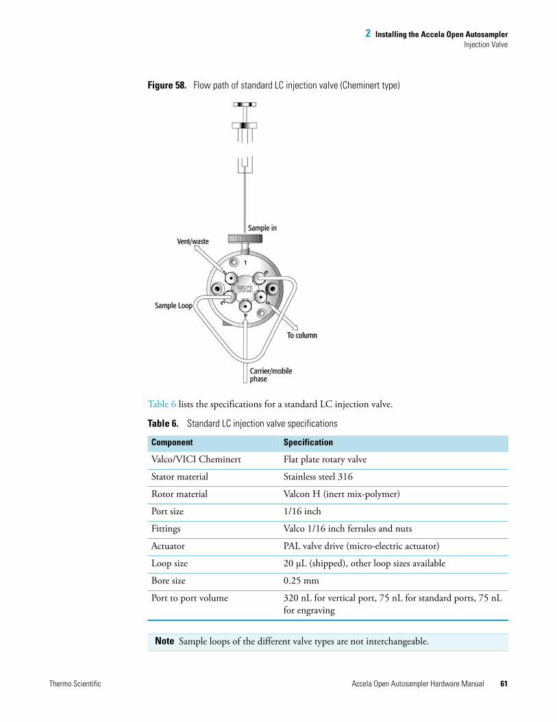
2 Installing the Accela Open AutosamplerInjection Valve
Thermo Scientific Accela Open Autosampler Hardware Manual 61
Figure 58. Flow path of standard LC injection valve (Cheminert type)
Table 6 lists the specifications for a standard LC injection valve.
Table 6. Standard LC injection valve specifications
Component Specification
Valco/VICI Cheminert Flat plate rotary valve
Stator material Stainless steel 316
Rotor material Valcon H (inert mix-polymer)
Port size 1/16 inch
Fittings Valco 1/16 inch ferrules and nuts
Actuator PAL valve drive (micro-electric actuator)
Loop size 20 μL (shipped), other loop sizes available
Bore size 0.25 mm
Port to port volume 320 nL for vertical port, 75 nL for standard ports, 75 nL for engraving
Note Sample loops of the different valve types are not interchangeable.
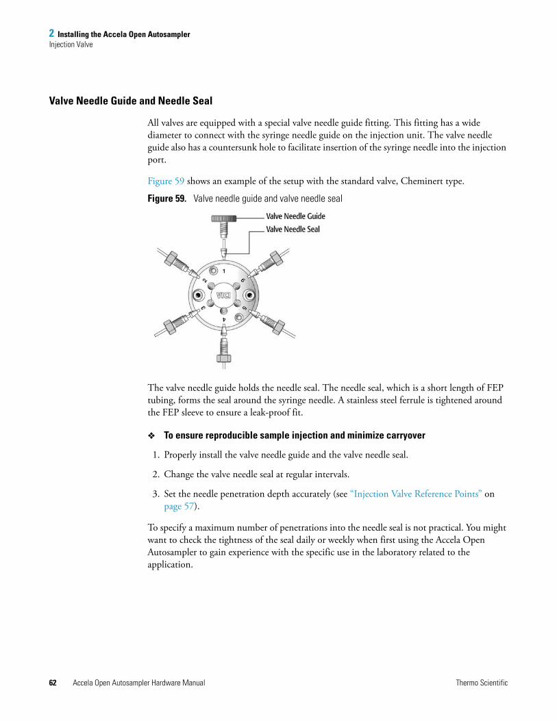
2 Installing the Accela Open AutosamplerInjection Valve
62 Accela Open Autosampler Hardware Manual Thermo Scientific
Valve Needle Guide and Needle Seal
All valves are equipped with a special valve needle guide fitting. This fitting has a wide diameter to connect with the syringe needle guide on the injection unit. The valve needle guide also has a countersunk hole to facilitate insertion of the syringe needle into the injection port.
Figure 59 shows an example of the setup with the standard valve, Cheminert type.
Figure 59. Valve needle guide and valve needle seal
The valve needle guide holds the needle seal. The needle seal, which is a short length of FEP tubing, forms the seal around the syringe needle. A stainless steel ferrule is tightened around the FEP sleeve to ensure a leak-proof fit.
To ensure reproducible sample injection and minimize carryover
1. Properly install the valve needle guide and the valve needle seal.
2. Change the valve needle seal at regular intervals.
3. Set the needle penetration depth accurately (see “Injection Valve Reference Points” on page 57).
To specify a maximum number of penetrations into the needle seal is not practical. You might want to check the tightness of the seal daily or weekly when first using the Accela Open Autosampler to gain experience with the specific use in the laboratory related to the application.
2 Installing the Accela Open AutosamplerInjection Valve
Thermo Scientific Accela Open Autosampler Hardware Manual 63
To test the tightness of the seal
1. Take the needle seal out of the valve port.
2. Manually insert a syringe needle gauge 22 (or gauge 22S) from the top, down into the tube, and past the sealing point of the ferrule.
3. If you observe a restriction, continue to use the needle seal. If not, replace the needle seal.
Interval to Replace Needle Seal
The interval to replace the needle seal depends on the number of penetrations. Consider these two factors for the decision to replace the needle seal:
• Leak, seal not reliable
Remove the needle seal from the inlet port and insert a syringe manually with the corresponding needle gauge (standard Gauge 22 OD 18/25 mm). Move the needle below the seal point of the ferrule. If you do not observe resistance at this point, replace the needle seal.
• Carryover
If you suspect any contamination of the needle seal with a compound, replace the needle seal.
Contamination can occur if the sample solution is accidentally dispensed too fast into the valve system. The restriction of valve and loop might cause backpressure, forcing the sample solution into the inlet port of the valve.
After running routinely for a few weeks, the warning limit for the inject counter gradually becomes evident and will be a valuable tool in routine work.
Path:
Menu > Info > Maintenance > Inject Limit (Inject counts reflect the actual number of injections.)
Table 7 lists the part numbers for replacement needle seals.
Note PAL Firmware (level 2.4.x or later) provides a counter for the number of injections performed using the PAL System. This counter monitors the valve switches and not the number of penetrations into the injection port; for example, cleaning the valve requires an extra penetration. You might want to monitor this counter in conjunction with the test for the tightness of the needle seal as described above.
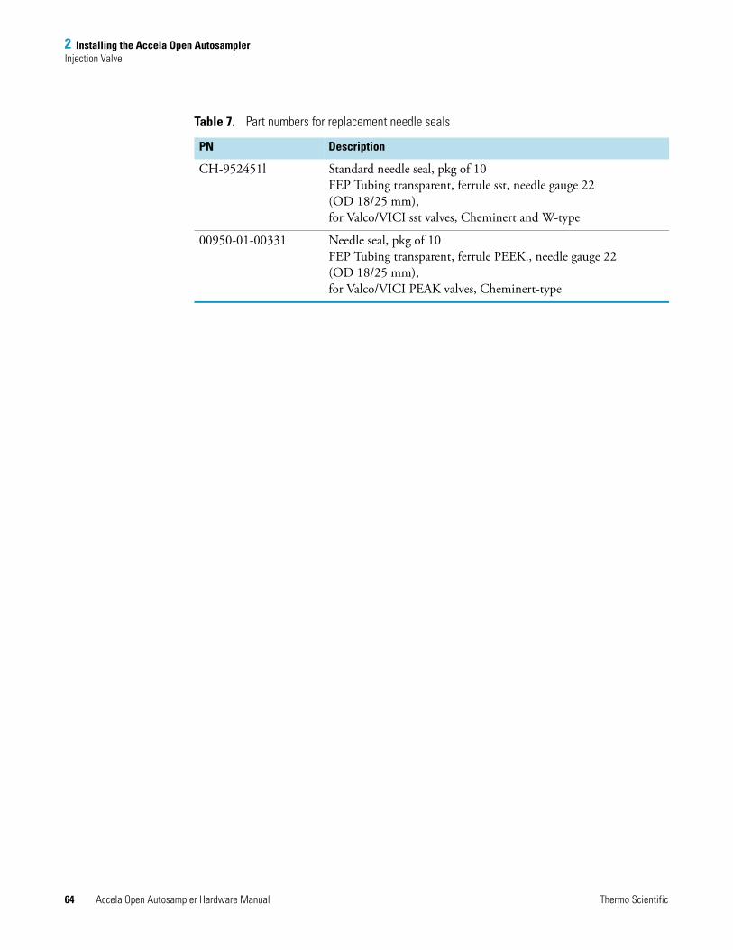
2 Installing the Accela Open AutosamplerInjection Valve
64 Accela Open Autosampler Hardware Manual Thermo Scientific
Table 7. Part numbers for replacement needle seals
PN Description
CH-952451l Standard needle seal, pkg of 10FEP Tubing transparent, ferrule sst, needle gauge 22 (OD 18/25 mm), for Valco/VICI sst valves, Cheminert and W-type
00950-01-00331 Needle seal, pkg of 10FEP Tubing transparent, ferrule PEEK., needle gauge 22 (OD 18/25 mm), for Valco/VICI PEAK valves, Cheminert-type
Thermo Scientific Accela Open Autosampler Hardware Manual 65
3
Operating the Accela Open Autosampler
This chapter describes how to operate the Accela Open Autosampler including how to use the control terminal, methods, job queue, utility functions, and logfile; and how to set up functions.
Control TerminalThe following procedures present the key steps required to set up and process multiple groups of samples with the Accela Open Autosampler. These procedures provide an overview for new users and a reminder for infrequent users. Make sure that the Accela Open Autosampler and all accessories are installed with objects defined correctly. In addition, ensure installation of a syringe of the specific type called for by a particular method.
Figure 60 illustrates the Open Autosampler control terminal and the conventions used to enter, edit, and view information.
Contents
• Control Terminal
• Methods
• Job and Job Queue
• Utility Functions
• Logfile
• Info Functions
• Setup Functions
• Communicating with the Computer
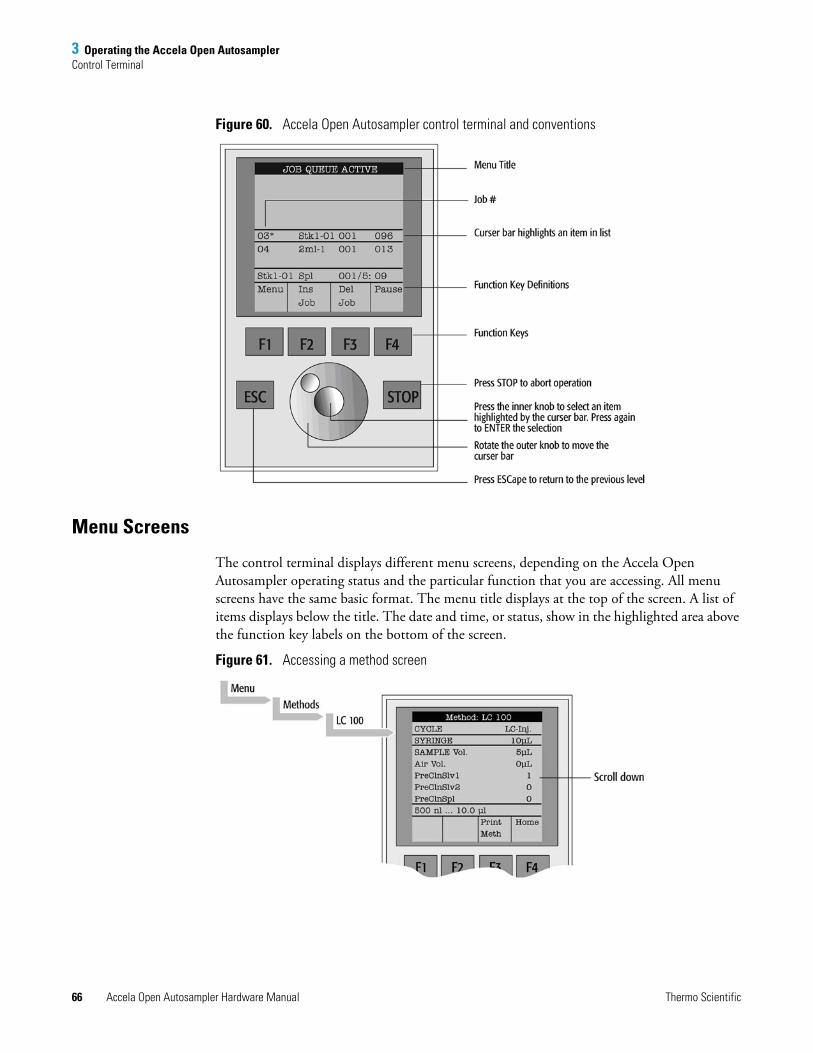
3 Operating the Accela Open AutosamplerControl Terminal
66 Accela Open Autosampler Hardware Manual Thermo Scientific
Figure 60. Accela Open Autosampler control terminal and conventions
Menu Screens
The control terminal displays different menu screens, depending on the Accela Open Autosampler operating status and the particular function that you are accessing. All menu screens have the same basic format. The menu title displays at the top of the screen. A list of items displays below the title. The date and time, or status, show in the highlighted area above the function key labels on the bottom of the screen.
Figure 61. Accessing a method screen
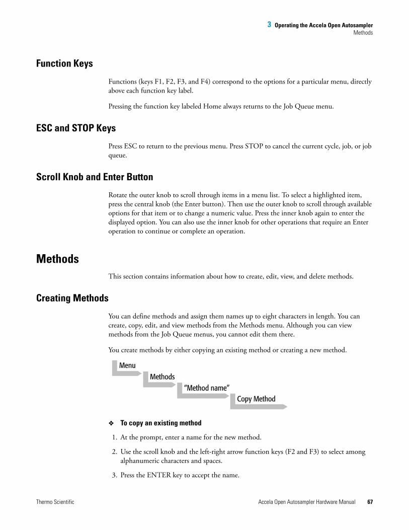
3 Operating the Accela Open AutosamplerMethods
Thermo Scientific Accela Open Autosampler Hardware Manual 67
Function Keys
Functions (keys F1, F2, F3, and F4) correspond to the options for a particular menu, directly above each function key label.
Pressing the function key labeled Home always returns to the Job Queue menu.
ESC and STOP Keys
Press ESC to return to the previous menu. Press STOP to cancel the current cycle, job, or job queue.
Scroll Knob and Enter Button
Rotate the outer knob to scroll through items in a menu list. To select a highlighted item, press the central knob (the Enter button). Then use the outer knob to scroll through available options for that item or to change a numeric value. Press the inner knob again to enter the displayed option. You can also use the inner knob for other operations that require an Enter operation to continue or complete an operation.
MethodsThis section contains information about how to create, edit, view, and delete methods.
Creating Methods
You can define methods and assign them names up to eight characters in length. You can create, copy, edit, and view methods from the Methods menu. Although you can view methods from the Job Queue menus, you cannot edit them there.
You create methods by either copying an existing method or creating a new method.
To copy an existing method
1. At the prompt, enter a name for the new method.
2. Use the scroll knob and the left-right arrow function keys (F2 and F3) to select among alphanumeric characters and spaces.
3. Press the ENTER key to accept the name.
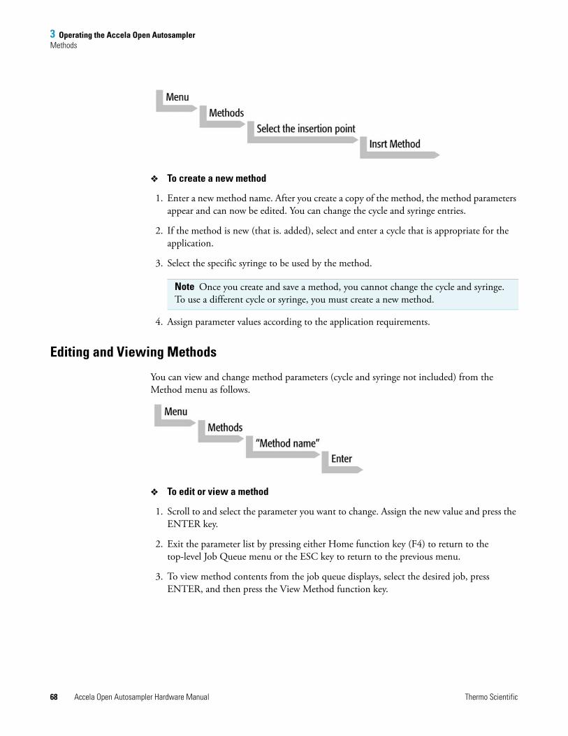
3 Operating the Accela Open AutosamplerMethods
68 Accela Open Autosampler Hardware Manual Thermo Scientific
To create a new method
1. Enter a new method name. After you create a copy of the method, the method parameters appear and can now be edited. You can change the cycle and syringe entries.
2. If the method is new (that is. added), select and enter a cycle that is appropriate for the application.
3. Select the specific syringe to be used by the method.
4. Assign parameter values according to the application requirements.
Editing and Viewing Methods
You can view and change method parameters (cycle and syringe not included) from the Method menu as follows.
To edit or view a method
1. Scroll to and select the parameter you want to change. Assign the new value and press the ENTER key.
2. Exit the parameter list by pressing either Home function key (F4) to return to the top-level Job Queue menu or the ESC key to return to the previous menu.
3. To view method contents from the job queue displays, select the desired job, press ENTER, and then press the View Method function key.
Note Once you create and save a method, you cannot change the cycle and syringe. To use a different cycle or syringe, you must create a new method.
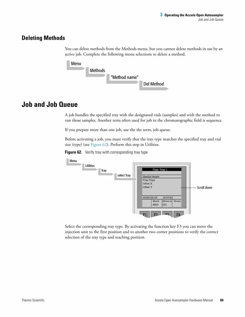
3 Operating the Accela Open AutosamplerJob and Job Queue
Thermo Scientific Accela Open Autosampler Hardware Manual 69
Deleting Methods
You can delete methods from the Methods menu, but you cannot delete methods in use by an active job. Complete the following menu selections to delete a method.
Job and Job QueueA job bundles the specified tray with the designated vials (samples) and with the method to run those samples. Another term often used for job in the chromatographic field is sequence.
If you prepare more than one job, use the the term, job queue.
Before activating a job, you must verify that the tray type matches the specified tray and vial size (type) (see Figure 62). Perform this step in Utilities.
Figure 62. Verify tray with corresponding tray type
Select the corresponding tray type. By activating the function key F3 you can move the injection unit to the first position and to another two corner positions to verify the correct selection of the tray type and teaching position.
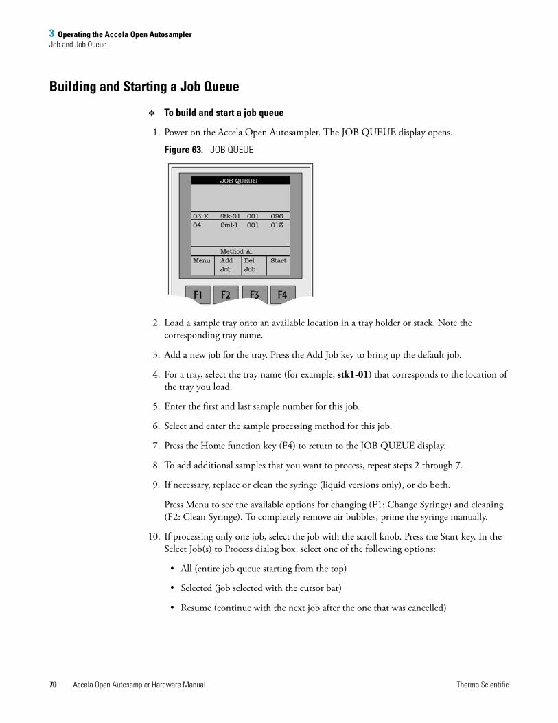
3 Operating the Accela Open AutosamplerJob and Job Queue
70 Accela Open Autosampler Hardware Manual Thermo Scientific
Building and Starting a Job Queue
To build and start a job queue
1. Power on the Accela Open Autosampler. The JOB QUEUE display opens.
Figure 63. JOB QUEUE
2. Load a sample tray onto an available location in a tray holder or stack. Note the corresponding tray name.
3. Add a new job for the tray. Press the Add Job key to bring up the default job.
4. For a tray, select the tray name (for example, stk1-01) that corresponds to the location of the tray you load.
5. Enter the first and last sample number for this job.
6. Select and enter the sample processing method for this job.
7. Press the Home function key (F4) to return to the JOB QUEUE display.
8. To add additional samples that you want to process, repeat steps 2 through 7.
9. If necessary, replace or clean the syringe (liquid versions only), or do both.
Press Menu to see the available options for changing (F1: Change Syringe) and cleaning (F2: Clean Syringe). To completely remove air bubbles, prime the syringe manually.
10. If processing only one job, select the job with the scroll knob. Press the Start key. In the Select Job(s) to Process dialog box, select one of the following options:
• All (entire job queue starting from the top)
• Selected (job selected with the cursor bar)
• Resume (continue with the next job after the one that was cancelled)
3 Operating the Accela Open AutosamplerUtility Functions
Thermo Scientific Accela Open Autosampler Hardware Manual 71
Cancelling a Job Queue
To cancel a job queue
1. In the JOB QUEUE display, press STOP.
2. Select one of the available options:
Continue, Sample, Job, or Job Queue.
• To resume processing with the current sample, select Continue.
• If there is a problem with only the current sample, select Sample. Processing resumes with the next sample.
• To cancel processing all samples in the current job, select Job. Processing resumes with the next job. The cancelled job is marked with an X.)
• To cancel processing all jobs, select Job Queue. The JOB QUEUE display appears. The cancelled job is marked with an X.
Restarting a Cancelled Job Queue
To restart a cancelled job queue
1. In the JOB QUEUE display, press START.
2. Select Resume. The job after the last one marked as cancelled starts.
Utility FunctionsUtility functions, selectable from the Menu display, provide quick access to checking operations and parameters that you might need to change. These functions are available for the actual syringe, trays, injectors, and wash station. They provide access to key functions without having to set up and execute a method and job.
Note If the sample processing cycle uses an item, the method value overwrites the appropriate utility value.
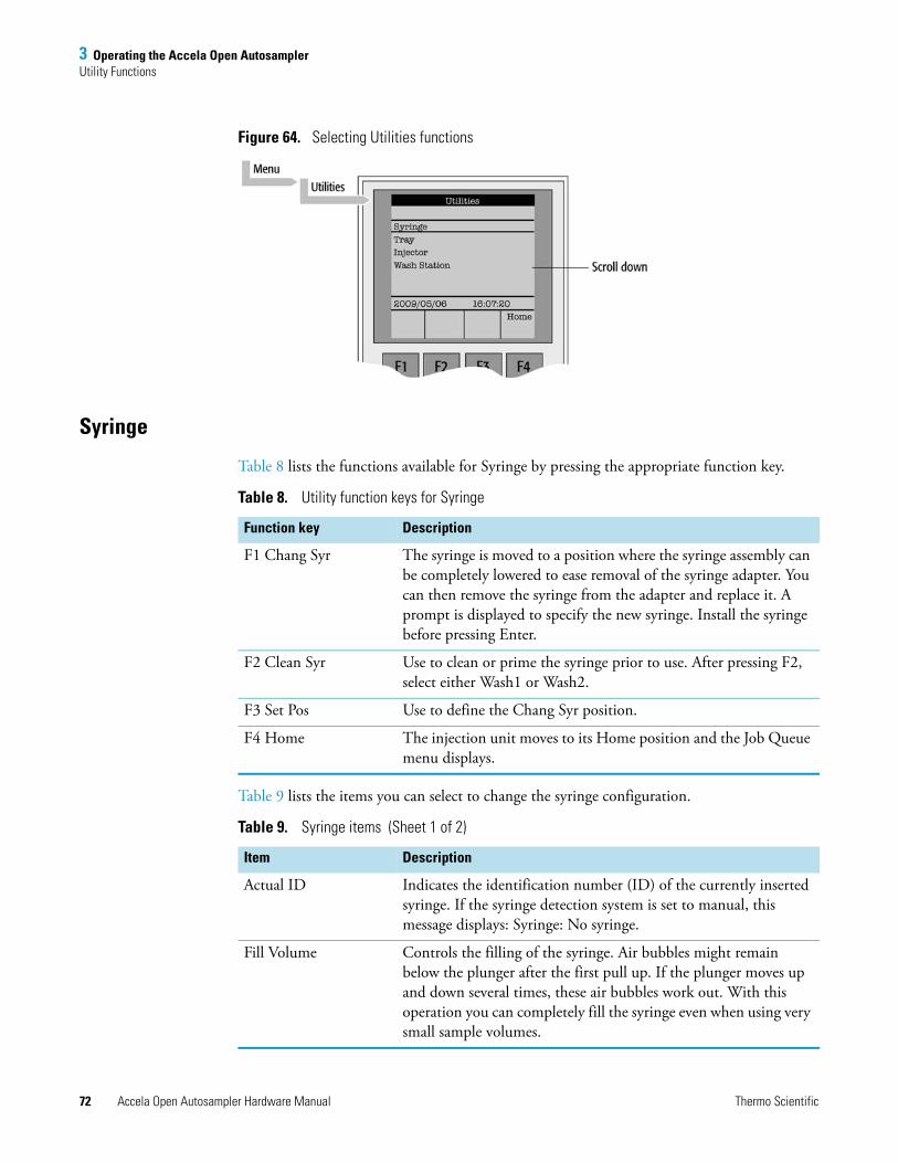
3 Operating the Accela Open AutosamplerUtility Functions
72 Accela Open Autosampler Hardware Manual Thermo Scientific
Figure 64. Selecting Utilities functions
Syringe
Table 8 lists the functions available for Syringe by pressing the appropriate function key.
Table 9 lists the items you can select to change the syringe configuration.
Table 8. Utility function keys for Syringe
Function key Description
F1 Chang Syr The syringe is moved to a position where the syringe assembly can be completely lowered to ease removal of the syringe adapter. You can then remove the syringe from the adapter and replace it. A prompt is displayed to specify the new syringe. Install the syringe before pressing Enter.
F2 Clean Syr Use to clean or prime the syringe prior to use. After pressing F2, select either Wash1 or Wash2.
F3 Set Pos Use to define the Chang Syr position.
F4 Home The injection unit moves to its Home position and the Job Queue menu displays.
Table 9. Syringe items (Sheet 1 of 2)
Item Description
Actual ID Indicates the identification number (ID) of the currently inserted syringe. If the syringe detection system is set to manual, this message displays: Syringe: No syringe.
Fill Volume Controls the filling of the syringe. Air bubbles might remain below the plunger after the first pull up. If the plunger moves up and down several times, these air bubbles work out. With this operation you can completely fill the syringe even when using very small sample volumes.
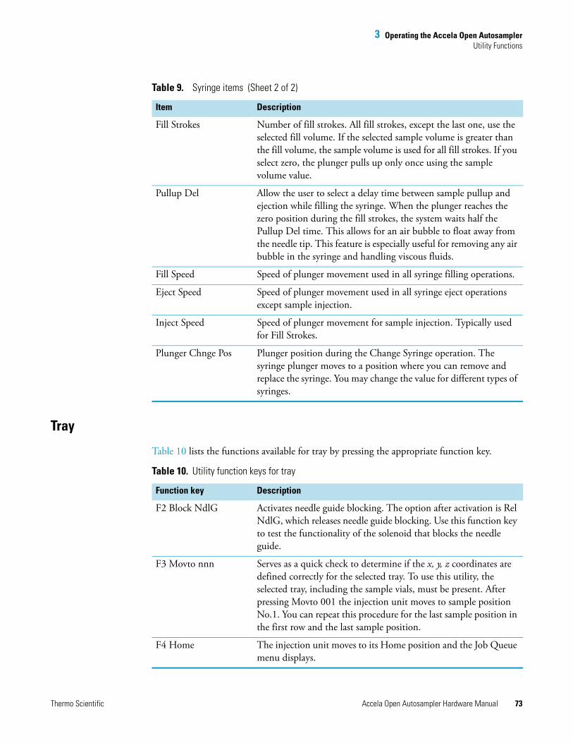
3 Operating the Accela Open AutosamplerUtility Functions
Thermo Scientific Accela Open Autosampler Hardware Manual 73
Tray
Table 10 lists the functions available for tray by pressing the appropriate function key.
Fill Strokes Number of fill strokes. All fill strokes, except the last one, use the selected fill volume. If the selected sample volume is greater than the fill volume, the sample volume is used for all fill strokes. If you select zero, the plunger pulls up only once using the sample volume value.
Pullup Del Allow the user to select a delay time between sample pullup and ejection while filling the syringe. When the plunger reaches the zero position during the fill strokes, the system waits half the Pullup Del time. This allows for an air bubble to float away from the needle tip. This feature is especially useful for removing any air bubble in the syringe and handling viscous fluids.
Fill Speed Speed of plunger movement used in all syringe filling operations.
Eject Speed Speed of plunger movement used in all syringe eject operations except sample injection.
Inject Speed Speed of plunger movement for sample injection. Typically used for Fill Strokes.
Plunger Chnge Pos Plunger position during the Change Syringe operation. The syringe plunger moves to a position where you can remove and replace the syringe. You may change the value for different types of syringes.
Table 9. Syringe items (Sheet 2 of 2)
Item Description
Table 10. Utility function keys for tray
Function key Description
F2 Block NdlG Activates needle guide blocking. The option after activation is Rel NdlG, which releases needle guide blocking. Use this function key to test the functionality of the solenoid that blocks the needle guide.
F3 Movto nnn Serves as a quick check to determine if the x, y, z coordinates are defined correctly for the selected tray. To use this utility, the selected tray, including the sample vials, must be present. After pressing Movto 001 the injection unit moves to sample position No.1. You can repeat this procedure for the last sample position in the first row and the last sample position.
F4 Home The injection unit moves to its Home position and the Job Queue menu displays.
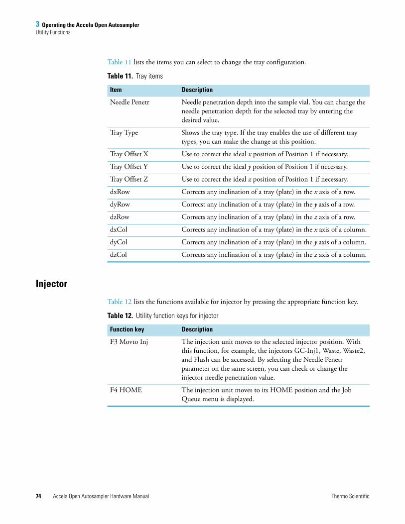
3 Operating the Accela Open AutosamplerUtility Functions
74 Accela Open Autosampler Hardware Manual Thermo Scientific
Table 11 lists the items you can select to change the tray configuration.
Injector
Table 12 lists the functions available for injector by pressing the appropriate function key.
Table 11. Tray items
Item Description
Needle Penetr Needle penetration depth into the sample vial. You can change the needle penetration depth for the selected tray by entering the desired value.
Tray Type Shows the tray type. If the tray enables the use of different tray types, you can make the change at this position.
Tray Offset X Use to correct the ideal x position of Position 1 if necessary.
Tray Offset Y Use to correct the ideal y position of Position 1 if necessary.
Tray Offset Z Use to correct the ideal z position of Position 1 if necessary.
dxRow Corrects any inclination of a tray (plate) in the x axis of a row.
dyRow Correcst any inclination of a tray (plate) in the y axis of a row.
dzRow Corrects any inclination of a tray (plate) in the z axis of a row.
dxCol Corrects any inclination of a tray (plate) in the x axis of a column.
dyCol Corrects any inclination of a tray (plate) in the y axis of a column.
dzCol Corrects any inclination of a tray (plate) in the z axis of a column.
Table 12. Utility function keys for injector
Function key Description
F3 Movto Inj The injection unit moves to the selected injector position. With this function, for example, the injectors GC-Inj1, Waste, Waste2, and Flush can be accessed. By selecting the Needle Penetr parameter on the same screen, you can check or change the injector needle penetration value.
F4 HOME The injection unit moves to its HOME position and the Job Queue menu is displayed.
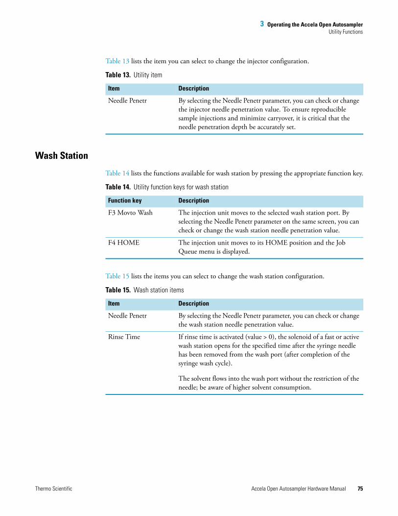
3 Operating the Accela Open AutosamplerUtility Functions
Thermo Scientific Accela Open Autosampler Hardware Manual 75
Table 13 lists the item you can select to change the injector configuration.
Wash Station
Table 14 lists the functions available for wash station by pressing the appropriate function key.
Table 15 lists the items you can select to change the wash station configuration.
Table 13. Utility item
Item Description
Needle Penetr By selecting the Needle Penetr parameter, you can check or change the injector needle penetration value. To ensure reproducible sample injections and minimize carryover, it is critical that the needle penetration depth be accurately set.
Table 14. Utility function keys for wash station
Function key Description
F3 Movto Wash The injection unit moves to the selected wash station port. By selecting the Needle Penetr parameter on the same screen, you can check or change the wash station needle penetration value.
F4 HOME The injection unit moves to its HOME position and the Job Queue menu is displayed.
Table 15. Wash station items
Item Description
Needle Penetr By selecting the Needle Penetr parameter, you can check or change the wash station needle penetration value.
Rinse Time If rinse time is activated (value > 0), the solenoid of a fast or active wash station opens for the specified time after the syringe needle has been removed from the wash port (after completion of the syringe wash cycle).
The solvent flows into the wash port without the restriction of the needle; be aware of higher solvent consumption.
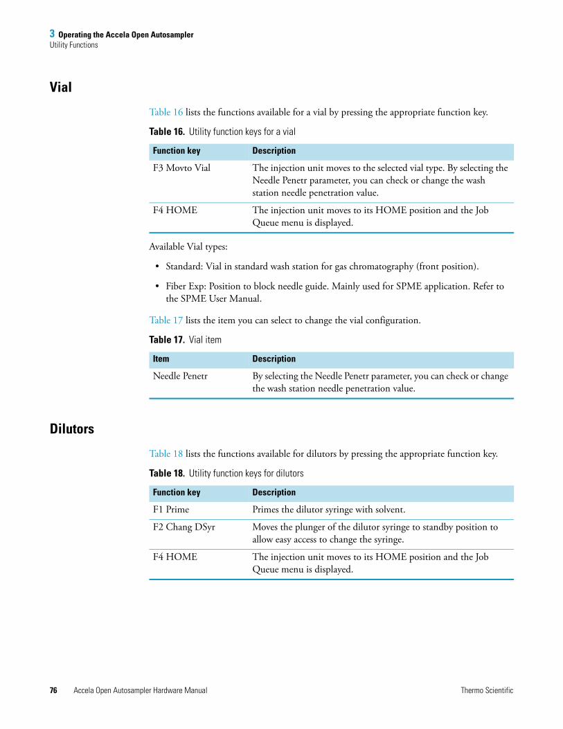
3 Operating the Accela Open AutosamplerUtility Functions
76 Accela Open Autosampler Hardware Manual Thermo Scientific
Vial
Table 16 lists the functions available for a vial by pressing the appropriate function key.
Available Vial types:
• Standard: Vial in standard wash station for gas chromatography (front position).
• Fiber Exp: Position to block needle guide. Mainly used for SPME application. Refer to the SPME User Manual.
Table 17 lists the item you can select to change the vial configuration.
Dilutors
Table 18 lists the functions available for dilutors by pressing the appropriate function key.
Table 16. Utility function keys for a vial
Function key Description
F3 Movto Vial The injection unit moves to the selected vial type. By selecting the Needle Penetr parameter, you can check or change the wash station needle penetration value.
F4 HOME The injection unit moves to its HOME position and the Job Queue menu is displayed.
Table 17. Vial item
Item Description
Needle Penetr By selecting the Needle Penetr parameter, you can check or change the wash station needle penetration value.
Table 18. Utility function keys for dilutors
Function key Description
F1 Prime Primes the dilutor syringe with solvent.
F2 Chang DSyr Moves the plunger of the dilutor syringe to standby position to allow easy access to change the syringe.
F4 HOME The injection unit moves to its HOME position and the Job Queue menu is displayed.
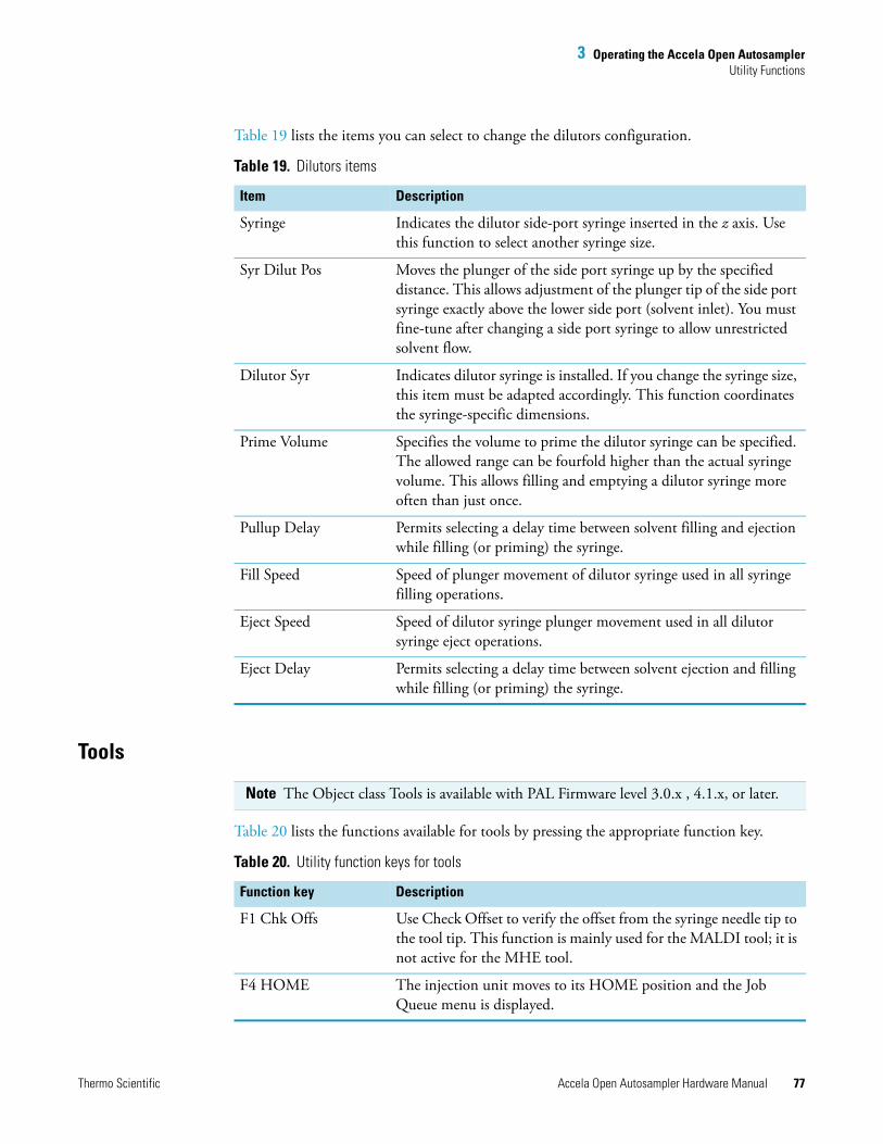
3 Operating the Accela Open AutosamplerUtility Functions
Thermo Scientific Accela Open Autosampler Hardware Manual 77
Table 19 lists the items you can select to change the dilutors configuration.
Tools
Table 20 lists the functions available for tools by pressing the appropriate function key.
Table 19. Dilutors items
Item Description
Syringe Indicates the dilutor side-port syringe inserted in the z axis. Use this function to select another syringe size.
Syr Dilut Pos Moves the plunger of the side port syringe up by the specified distance. This allows adjustment of the plunger tip of the side port syringe exactly above the lower side port (solvent inlet). You must fine-tune after changing a side port syringe to allow unrestricted solvent flow.
Dilutor Syr Indicates dilutor syringe is installed. If you change the syringe size, this item must be adapted accordingly. This function coordinates the syringe-specific dimensions.
Prime Volume Specifies the volume to prime the dilutor syringe can be specified. The allowed range can be fourfold higher than the actual syringe volume. This allows filling and emptying a dilutor syringe more often than just once.
Pullup Delay Permits selecting a delay time between solvent filling and ejection while filling (or priming) the syringe.
Fill Speed Speed of plunger movement of dilutor syringe used in all syringe filling operations.
Eject Speed Speed of dilutor syringe plunger movement used in all dilutor syringe eject operations.
Eject Delay Permits selecting a delay time between solvent ejection and filling while filling (or priming) the syringe.
Note The Object class Tools is available with PAL Firmware level 3.0.x , 4.1.x, or later.
Table 20. Utility function keys for tools
Function key Description
F1 Chk Offs Use Check Offset to verify the offset from the syringe needle tip to the tool tip. This function is mainly used for the MALDI tool; it is not active for the MHE tool.
F4 HOME The injection unit moves to its HOME position and the Job Queue menu is displayed.
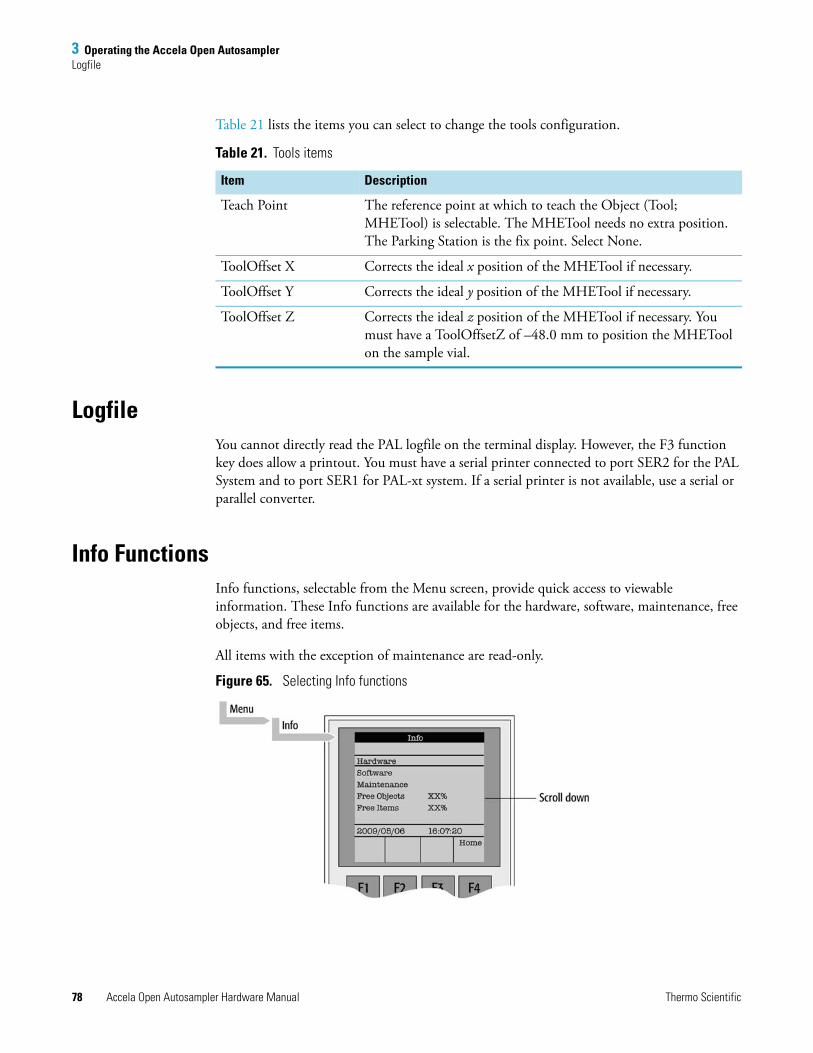
3 Operating the Accela Open AutosamplerLogfile
78 Accela Open Autosampler Hardware Manual Thermo Scientific
Table 21 lists the items you can select to change the tools configuration.
LogfileYou cannot directly read the PAL logfile on the terminal display. However, the F3 function key does allow a printout. You must have a serial printer connected to port SER2 for the PAL System and to port SER1 for PAL-xt system. If a serial printer is not available, use a serial or parallel converter.
Info FunctionsInfo functions, selectable from the Menu screen, provide quick access to viewable information. These Info functions are available for the hardware, software, maintenance, free objects, and free items.
All items with the exception of maintenance are read-only.
Figure 65. Selecting Info functions
Table 21. Tools items
Item Description
Teach Point The reference point at which to teach the Object (Tool; MHETool) is selectable. The MHETool needs no extra position. The Parking Station is the fix point. Select None.
ToolOffset X Corrects the ideal x position of the MHETool if necessary.
ToolOffset Y Corrects the ideal y position of the MHETool if necessary.
ToolOffset Z Corrects the ideal z position of the MHETool if necessary. You must have a ToolOffsetZ of –48.0 mm to position the MHETool on the sample vial.
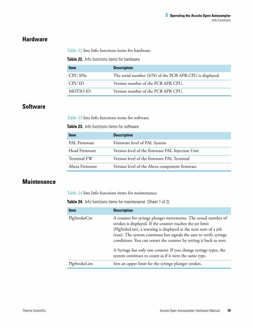
3 Operating the Accela Open AutosamplerInfo Functions
Thermo Scientific Accela Open Autosampler Hardware Manual 79
Hardware
Table 22 lists Info functions items for hardware.
Software
Table 23 lists Info functions items for software.
Maintenance
Table 24 lists Info functions items for maintenance.
Table 22. Info functions items for hardware
Item Description
CPU SNo The serial number (S/N) of the PCB APR CPU is displayed.
CPU ID Version number of the PCB APR CPU.
MOTIO ID Version number of the PCB APR CPU.
Table 23. Info functions items for software
Item Description
PAL Firmware Firmware level of PAL System
Head Firmware Version level of the firmware PAL Injection Unit
Terminal FW Version level of the firmware PAL Terminal
Altera Firmware Version level of the Altera component firmware
Table 24. Info functions items for maintenance (Sheet 1 of 2)
Item Description
PlgStrokeCnt A counter for syringe plunger movements. The actual number of strokes is displayed. If the counter reaches the set limit (PlgStrkeLim), a warning is displayed at the next start of a job (run). The system continues but signals the user to verify syringe conditions. You can restart the counter by setting it back to zero.
A Syringe has only one counter. If you change syringe types, the system continues to count as if it were the same type.
PlgStrokeLim Sets an upper limit for the syringe plunger strokes.
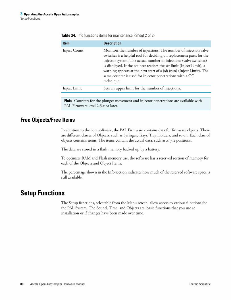
3 Operating the Accela Open AutosamplerSetup Functions
80 Accela Open Autosampler Hardware Manual Thermo Scientific
Free Objects/Free Items
In addition to the core software, the PAL Firmware contains data for firmware objects. There are different classes of Objects, such as Syringes, Trays, Tray Holders, and so on. Each class of objects contains items. The items contain the actual data, such as x, y, z positions.
The data are stored in a flash memory backed up by a battery.
To optimize RAM and Flash memory use, the software has a reserved section of memory for each of the Objects and Object Items.
The percentage shown in the Info section indicates how much of the reserved software space is still available.
Setup FunctionsThe Setup functions, selectable from the Menu screen, allow access to various functions for the PAL System. The Sound, Time, and Objects are basic functions that you use at installation or if changes have been made over time.
Inject Count Monitors the number of injections. The number of injection valve switches is a helpful tool for deciding on replacement parts for the injector system. The actual number of injections (valve switches) is displayed. If the counter reaches the set limit (Inject Limit), a warning appears at the next start of a job (run) (Inject Limit). The same counter is used for injector penetrations with a GC technique.
Inject Limit Sets an upper limit for the number of injections.
Note Counters for the plunger movement and injector penetrations are available with PAL Firmware level 2.5.x or later.
Table 24. Info functions items for maintenance (Sheet 2 of 2)
Item Description
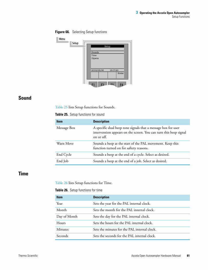
3 Operating the Accela Open AutosamplerSetup Functions
Thermo Scientific Accela Open Autosampler Hardware Manual 81
Figure 66. Selecting Setup functions
Sound
Table 25 lists Setup functions for Sounds.
Time
Table 26 lists Setup functions for Time.
Table 25. Setup functions for sound
Item Description
Message Box A specific dual beep tone signals that a message box for user intervention appears on the screen. You can turn this beep signal on or off.
Warn Move Sounds a beep at the start of the PAL movement. Keep this function turned on for saftety reasons.
End Cycle Sounds a beep at the end of a cycle. Select as desired.
End Job Sounds a beep at the end of a job. Select as desired.
Table 26. Setup functions for time
Item Description
Year Sets the year for the PAL internal clock.
Month Sets the month for the PAL internal clock.
Day of Month Sets the day for the PAL internal clock.
Hours Sets the hours for the PAL internal clock.
Minutes Sets the minutes for the PAL internal clock.
Seconds Sets the seconds for the PAL internal clock.
3 Operating the Accela Open AutosamplerCommunicating with the Computer
82 Accela Open Autosampler Hardware Manual Thermo Scientific
After setting or resetting the date and time, use the F1 function key (F1 Set Time) to save your changes.
Objects
You can directly access common functions for the various PAL Firmware Object classes. For a detailed listing, see “PAL Firmware Overview” on page 191.
Communicating with the ComputerThis section describes how the Accela Open Autosampler communicates with a computer.
The PAL System provides a serial communication protocol with a PC. The Accela Open Autosampler system requires a dedicated APR Control-xt board and PAL Firmware level 4.1.x or later.
The COM port settings are normally defined in:
Windows\Control Panel\Device Manager\Ports
Figure 67 shows the standard settings for the serial communication. Be aware that the application (for example, PAL Loader software) does actively set the communication parameters, and the baud rate is set for optimized use.
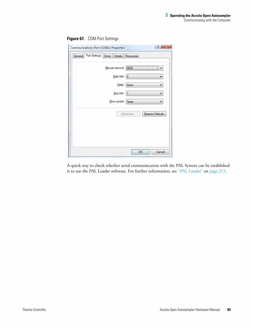
3 Operating the Accela Open AutosamplerCommunicating with the Computer
Thermo Scientific Accela Open Autosampler Hardware Manual 83
Figure 67. COM Port Settings
A quick way to check whether serial communication with the PAL System can be established is to use the PAL Loader software. For further information, see “PAL Loader” on page 211.

Thermo Scientific Accela Open Autosampler Hardware Manual 85
4
Installing Cycle Composer Macros or ICC Cycles Used for the DLW Option
You can only operate the Open Autosampler DLW option in combination with PAL control software, such as Thermo PAL driver for Xcalibur or Cycle Editor, for ICC interpretation in another data handling system software.
For software control, three macros or three cycles are provided.
The first of three macros covers the initial and daily priming of the solvent lines and covers a complete injection cycle, a second macro is used for Standard speed with optimized washing possibilities, and the last for a Fast cycle for optimized throughput and less focus on carryover. See Table 27.
For detailed descriptions of all macros (or cycles), see Table 27, Table 28, and Table 29.
Table 27. The DLW macro definitions
Macro name Macro description
Priming Accela Open For initial and daily routine priming of the solvent lines and DLW manifold. The Clean Time for both wash solvents is a variable for the user to define the intensity of washing.
Standard Injection Accela Open
Standard injection cycle using all possibilities of the DLW option. The injection valve inlet port and the needle are washed with both wash solvents (inside and out). You can add an extra Stator Wash for intensive washing of the injection valve (valve toggle).
Fast Injection Accela Open
Tuned for speed and high-throughput application. It differs from the Standard DLW macro in that some steps are left out to shorten the cycle time.
4 Installing Cycle Composer Macros or ICC Cycles Used for the DLW OptionInstalling the Thermo PAL Driver Macros or ICC Cycles
86 Accela Open Autosampler Hardware Manual Thermo Scientific
Installing the Thermo PAL Driver Macros or ICC CyclesThe Accela Open Autosampler is shipped with a CD-ROM containing various cycles for the DLW option. Macros for the Xcalibur data system are installed by the LC Devices 2.5 installer.
Copy these macros to your Thermo PAL driver method folder or corresponding folder for application within the integrated system.
To copy cycles to your Cycle Composer
1. Navigate in Windows™ Explorer to the Thermo PAL driver folder. The usual folder location is as follows:
drive:\Thermo\Instruments\LC Devices\ThermoPAL\PAL
2. If you wish to add the DLW option macros to an existing method folder, copy the macros (*.pma) and the methods (*.pme) files from the DLW Option folder on the CD-ROM to the method folder.
If the PAL System is integrated in a data system software that controls the PAL using the Cycle Editor for PAL ICC interpretation (for example, Analyst, ChemStation, Empower, EZChrom, MassLynx, Xcalibur), an ICC Cycle is used and not the Cycle Composer Macro. The cycle extension is *.cyx.
General ConsiderationsYou must establish the duration of the wash steps for each configuration and application. Consider factors such as the viscosity and surface tension of the individual wash solvent composition and the backpressure of the system.
Be aware that a higher backpressure builds up if the valve bore size (standard valve bore 0.25 mm) or the installed loop internal diameter is lower. Standard loop internal diameter (ID) for Thermo-defined loops with a volume of 5, 10, and 20 μL is 0.25 mm. The loop with 2 μL content volume has an ID of 0.125 mm.
Keep the tubing internal diameters of the tubing in line with the valve dimensions, loop ID, and flow rate.
Note You can convert a Cycle Composer macro to a cycle (extension *.cyx) by using the Cycle Editor software. Conversion is available starting with Cycle Editor version 1.4.0.4.
Note The provided macros are written for standard injection valve drives, which are controlled and activated through the AUX interface.
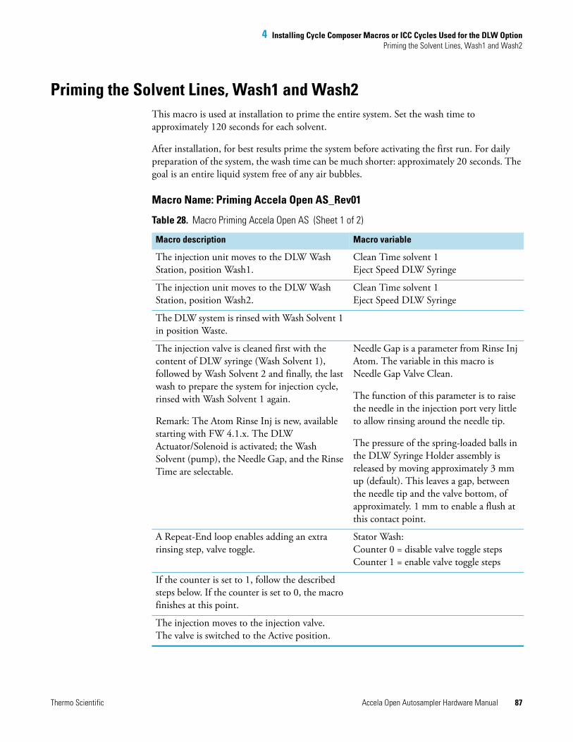
4 Installing Cycle Composer Macros or ICC Cycles Used for the DLW OptionPriming the Solvent Lines, Wash1 and Wash2
Thermo Scientific Accela Open Autosampler Hardware Manual 87
Priming the Solvent Lines, Wash1 and Wash2This macro is used at installation to prime the entire system. Set the wash time to approximately 120 seconds for each solvent.
After installation, for best results prime the system before activating the first run. For daily preparation of the system, the wash time can be much shorter: approximately 20 seconds. The goal is an entire liquid system free of any air bubbles.
Macro Name: Priming Accela Open AS_Rev01
Table 28. Macro Priming Accela Open AS (Sheet 1 of 2)
Macro description Macro variable
The injection unit moves to the DLW Wash Station, position Wash1.
Clean Time solvent 1Eject Speed DLW Syringe
The injection unit moves to the DLW Wash Station, position Wash2.
Clean Time solvent 1Eject Speed DLW Syringe
The DLW system is rinsed with Wash Solvent 1 in position Waste.
The injection valve is cleaned first with the content of DLW syringe (Wash Solvent 1), followed by Wash Solvent 2 and finally, the last wash to prepare the system for injection cycle, rinsed with Wash Solvent 1 again.
Remark: The Atom Rinse Inj is new, available starting with FW 4.1.x. The DLW Actuator/Solenoid is activated; the Wash Solvent (pump), the Needle Gap, and the Rinse Time are selectable.
Needle Gap is a parameter from Rinse Inj Atom. The variable in this macro is Needle Gap Valve Clean.
The function of this parameter is to raise the needle in the injection port very little to allow rinsing around the needle tip.
The pressure of the spring-loaded balls in the DLW Syringe Holder assembly is released by moving approximately 3 mm up (default). This leaves a gap, between the needle tip and the valve bottom, of approximately. 1 mm to enable a flush at this contact point.
A Repeat-End loop enables adding an extra rinsing step, valve toggle.
Stator Wash: Counter 0 = disable valve toggle stepsCounter 1 = enable valve toggle steps
If the counter is set to 1, follow the described steps below. If the counter is set to 0, the macro finishes at this point.
The injection moves to the injection valve.The valve is switched to the Active position.
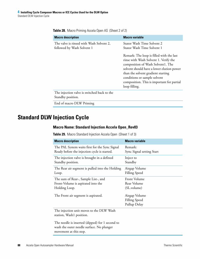
4 Installing Cycle Composer Macros or ICC Cycles Used for the DLW OptionStandard DLW Injection Cycle
88 Accela Open Autosampler Hardware Manual Thermo Scientific
Standard DLW Injection Cycle
Macro Name: Standard Injection Accela Open_Rev03
The valve is rinsed with Wash Solvent 2, followed by Wash Solvent 1
Stator Wash Time Solvent 2Stator Wash Time Solvent 1
Remark: The loop is filled with the last rinse with Wash Solvent 1. Verify the composition of Wash Solvent1. The solvent should have a lower elution power than the solvent gradient starting conditions or sample solvent composition. This is important for partial loop filling.
The injection valve is switched back to the Standby position.
End of macro DLW Priming
Table 28. Macro Priming Accela Open AS (Sheet 2 of 2)
Macro description Macro variable
Table 29. Macro Standard Injection Accela Open (Sheet 1 of 3)
Macro description Macro variable
The PAL System waits first for the Sync Signal Ready before the injection cycle is started.
Remark:Sync Signal setting Start
The injection valve is brought in a defined Standby position.
Inject to Standby
The Rear air segment is pulled into the Holding Loop.
Airgap Volume Filling Speed
The sum of Rear-, Sample List-, and Front-Volume is aspirated into the Holding Loop.
The Front air segment is aspirated.
Front VolumeRear Volume(SL.volume)
Airgap VolumeFilling SpeedPullup Delay
The injection unit moves to the DLW Wash station, Wash1 position.
The needle is inserted (dipped) for 1 second to wash the outer needle surface. No plunger movement at this step.
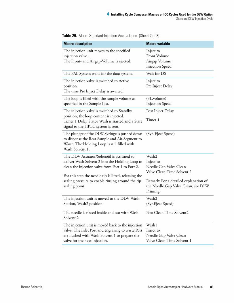
4 Installing Cycle Composer Macros or ICC Cycles Used for the DLW OptionStandard DLW Injection Cycle
Thermo Scientific Accela Open Autosampler Hardware Manual 89
The injection unit moves to the specified injection valve.The Front- and Airgap-Volume is ejected.
Inject toFront VolumeAirgap VolumeInjection Speed
The PAL System waits for the data system. Wait for DS
The injection valve is switched to Active position.The time Pre Inject Delay is awaited.
Inject toPre Inject Delay
The loop is filled with the sample volume as specified in the Sample List.
(SL.volume)Injection Speed
The injection valve is switched to Standby position; the loop content is injected.Timer 1 Delay Stator Wash is started and a Start signal to the HPLC system is sent.
Post Inject Delay
Timer 1
The plunger of the DLW Syringe is pushed down to dispense the Rear Sample and Air Segment to Waste. The Holding Loop is still filled with Wash Solvent 1.
(Syr. Eject Speed)
The DLW Actuator/Solenoid is activated to deliver Wash Solvent 2 into the Holding Loop to clean the injection valve from Port 1 to Port 2.
For this step the needle tip is lifted, releasing the sealing pressure to enable rinsing around the tip sealing point.
Wash2Inject toNeedle Gap Valve CleanValve Clean Time Solvent 2
Remark: For a detailed explanation of the Needle Gap Valve Clean, see DLW Priming.
The injection unit is moved to the DLW Wash Station, Wash2 position.
The needle is rinsed inside and out with Wash Solvent 2.
Wash2(Syr.Eject Speed)
Post Clean Time Solvent2
The injection unit is moved back to the injection valve. The Inlet Port and engraving to waste Port are flushed with Wash Solvent 1 to prepare the valve for the next injection.
Wash1Inject toNeedle Gap Valve CleanValve Clean Time Solvent 1
Table 29. Macro Standard Injection Accela Open (Sheet 2 of 3)
Macro description Macro variable
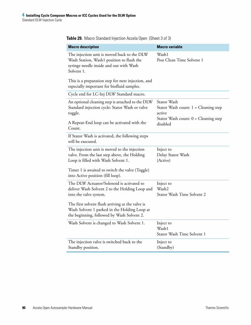
4 Installing Cycle Composer Macros or ICC Cycles Used for the DLW OptionStandard DLW Injection Cycle
90 Accela Open Autosampler Hardware Manual Thermo Scientific
The injection unit is moved back to the DLW Wash Station, Wash1 position to flush the syringe needle inside and out with Wash Solvent 1.
This is a preparation step for next injection, and especially important for biofluid samples.
Wash1Post Clean Time Solvent 1
Cycle end for LC-Inj DLW Standard macro.
An optional cleaning step is attached to the DLW Standard injection cycle: Stator Wash or valve toggle.
A Repeat-End loop can be activated with the Count.
Stator WashStator Wash count: 1 = Cleaning step activeStator Wash count: 0 = Cleaning step disabled
If Stator Wash is activated, the following steps will be executed.
The injection unit is moved to the injection valve. From the last step above, the Holding Loop is filled with Wash Solvent 1.
Timer 1 is awaited to switch the valve (Toggle) into Active position (fill loop).
Inject toDelay Stator Wash(Active)
The DLW Actuator/Solenoid is activated to deliver Wash Solvent 2 to the Holding Loop and into the valve system.
The first solvent flush arriving at the valve is Wash Solvent 1 parked in the Holding Loop at the beginning, followed by Wash Solvent 2.
Inject toWash2Stator Wash Time Solvent 2
Wash Solvent is changed to Wash Solvent 1. Inject toWash1Stator Wash Time Solvent 1
The injection valve is switched back to the Standby position.
Inject to(Standby)
Table 29. Macro Standard Injection Accela Open (Sheet 3 of 3)
Macro description Macro variable

4 Installing Cycle Composer Macros or ICC Cycles Used for the DLW OptionFast DLW Injection Cycle
Thermo Scientific Accela Open Autosampler Hardware Manual 91
Fast DLW Injection CycleThe Fast injection cycle differs from the Standard cycle as follows:
• The needle is not dipped in the Wash station Wash1 after sample pickup and before it moves to the injection valve.
• The wash steps after injection are reduced to Valve Clean with Wash Solvent 1 and Wash Solvent 2. The DLW needle is flushed in the DLW Wash Station with Wash Solvent 1 only.
• Stator Wash (valve toggle) is not available.
Macro Name: Fast Injection Accela Open_Rev03
Table 30. Macro Fast Injection Accela Open (Sheet 1 of 2)
Macro description Macro variable
The PAL System waits first for the Sync Signal Ready before the injection cycle is started.
Remark:Sync Signal setting Start
The injection valve is brought to a defined position: Standby.
Inject toStandby
The Rear air segment is pulled into the Holding Loop.
Airgap VolumeFilling Speed
The sum of Rear-, Sample List-, and Front-Volume is aspirated into the Holding Loop.
The Front air segment is aspirated.
Front VolumeRear Volume(SL.volume)Airgap VolumeFilling SpeedPullup Delay
The injection unit moves to the specified injection valve.The Front- and Airgap-Volume is ejected to Waste.
Inject toFront VolumeAirgap VolumeInjection Speed
The PAL System waits for the data system Wait for DS
The injection valve is switched to Active position.The Pre Inject Delay time is awaited.
The loop is filled with the sample volume as specified in the sample list.
The injection valve is switched to Standby position, the loop content is injected.
Inject to
Pre Injection Delay
(SL.volume)
Injection SpeedPost Inject Delay
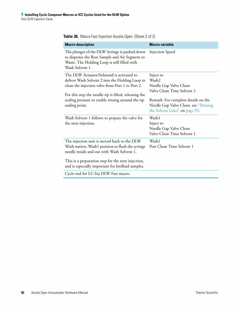
4 Installing Cycle Composer Macros or ICC Cycles Used for the DLW OptionFast DLW Injection Cycle
92 Accela Open Autosampler Hardware Manual Thermo Scientific
The plunger of the DLW Syringe is pushed down to dispense the Rear Sample and Air Segment to Waste. The Holding Loop is still filled with Wash Solvent 1.
Injection Speed
The DLW Actuator/Solenoid is activated to deliver Wash Solvent 2 into the Holding Loop to clean the injection valve from Port 1 to Port 2.
For this step the needle tip is lifted, releasing the sealing pressure to enable rinsing around the tip sealing point.
Inject toWash2Needle Gap Valve CleanValve Clean Time Solvent 2
Remark: For complete details on the Needle Gap Valve Clean, see “Priming the Solvent Lines” on page 93.
Wash Solvent 1 follows to prepare the valve for the next injection.
Wash1Inject toNeedle Gap Valve CleanValve Clean Time Solvent 1
The injection unit is moved back to the DLW Wash station, Wash1 position to flush the syringe needle inside and out with Wash Solvent 1.
This is a preparation step for the next injection, and is especially important for biofluid samples.
Wash1Post Clean Time Solvent 1
Cycle end for LC-Inj DLW Fast macro.
Table 30. Macro Fast Injection Accela Open (Sheet 2 of 2)
Macro description Macro variable
Thermo Scientific Accela Open Autosampler Hardware Manual 93
5
Operating Dynamic Load and Wash (DLW)
This chapter describes how to operate the Dynamic Load and Wash (DLW) option.
Priming the Solvent Lines
In order to make the initial and daily priming efficient and controllable, the Open Autosampler comes with a Thermo PAL driver macro, or ICC cycle.
For information on macros, see “Installing Cycle Composer Macros or ICC Cycles Used for the DLW Option” on page 85.
To prime the solvent lines
1. Load the macros and methods into the folder.
2. Start the corresponding macro for initial or daily priming.
3. Check the solvent lines and prime until air bubbles are no longer visible.
4. Press F4 for Home.
Location of Solvent and Waste BottlesThe DLW option contains self-priming membrane pumps. The solvent bottles can be placed either in the fast wash station holder or on the lab bench.
Contents
• Priming the Solvent Lines
• Location of Solvent and Waste Bottles
• Functionality of the DLW Option
• DLW Cycle Step-By-Step
Tip For trouble-free DLW operation, make sure the two solvent lines are free of air bubbles at all times. If the solvent lines are being connected for the first time or during a solvent change, you must prime the solvent lines properly until air bubbles are no longer visible. For best results, use solvent degassing.
5 Operating Dynamic Load and Wash (DLW)Functionality of the DLW Option
94 Accela Open Autosampler Hardware Manual Thermo Scientific
You must place the Waste bottle greater than 30 cm (12 in.) below the injection valve. Make sure that the waste liquid can flow into the waste bottle without restriction. Place the waste tubing above the level of the liquid. Ideally, the tube is fixed at the neck of the waste bottle.
Functionality of the DLW OptionThis section contains information about the functionality of the DLW option, including the DLW pumps and the DLW Actuator/Solenoid.
DLW Pumps
From the control viewpoint, the DLW pumps respond in the same manner as the fast wash station. Power-out signals activate the pumps. Because the electric current setting for the DLW is different, the corresponding PAL Firmware Objects must be loaded for the DLW wash station type.
The wetted parts in the pump are made from the following materials:
• Membrane: Kalrez (FFPM)
• Body, valves: Ryton PPS
The pumps are self priming with a suction lift of up to a 3 m water column.
DLW Actuator/Solenoid
The DLW Actuator/Solenoid has the function of separating and completely shutting off the lines in the direction of the syringe (sample loading) or the wash solvent lines.
After opening the DLW Actuator/Solenoid for the wash solvent lines, you can pump the desired wash solvent into the system by activating the corresponding DLW pump.
Figure 68 illustrates this functionality.
The wetted parts in the DLW Actuator Solenoid are made from the following materials:
• Solenoid body: PEEK
• Seal material: FFKM (Simriz)
Tip Use good laboratory practice to avoid contaminating the wash solvents and the wash bottles. Avoid biological growth in pure water by either replacing it regularly or adding a small percentage of organic solvents, such as methanol or acetonitrile. Certain buffer solutions can decompose at room temperature when exposed to light. Filtering the wash solvents before filling the bottle, especially if using salt buffers, is mandatory to avoid any clogging of the solvent paths.
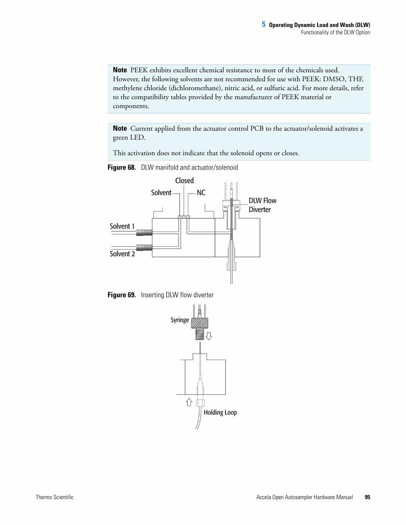
5 Operating Dynamic Load and Wash (DLW)Functionality of the DLW Option
Thermo Scientific Accela Open Autosampler Hardware Manual 95
Figure 68. DLW manifold and actuator/solenoid
Figure 69. Inserting DLW flow diverter
Note PEEK exhibits excellent chemical resistance to most of the chemicals used. However, the following solvents are not recommended for use with PEEK: DMSO, THF, methylene chloride (dichloromethane), nitric acid, or sulfuric acid. For more details, refer to the compatibility tables provided by the manufacturer of PEEK material or components.
Note Current applied from the actuator control PCB to the actuator/solenoid activates a green LED.
This activation does not indicate that the solenoid opens or closes.
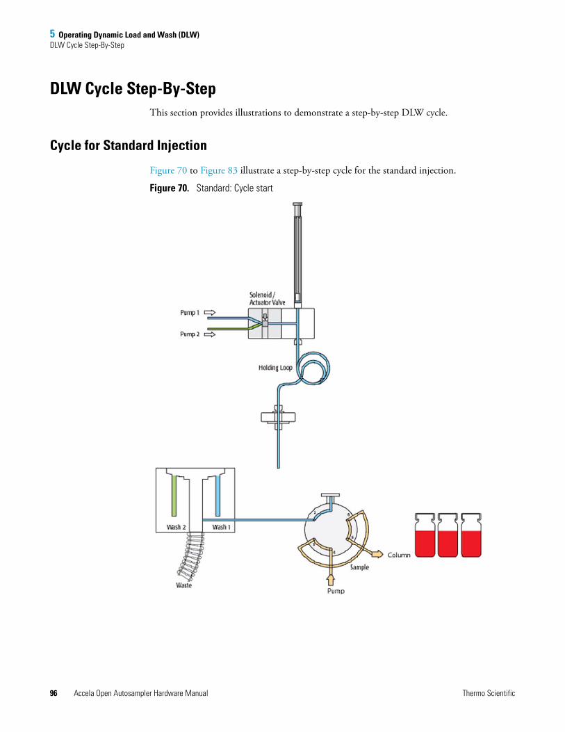
5 Operating Dynamic Load and Wash (DLW)DLW Cycle Step-By-Step
96 Accela Open Autosampler Hardware Manual Thermo Scientific
DLW Cycle Step-By-StepThis section provides illustrations to demonstrate a step-by-step DLW cycle.
Cycle for Standard Injection
Figure 70 to Figure 83 illustrate a step-by-step cycle for the standard injection.
Figure 70. Standard: Cycle start
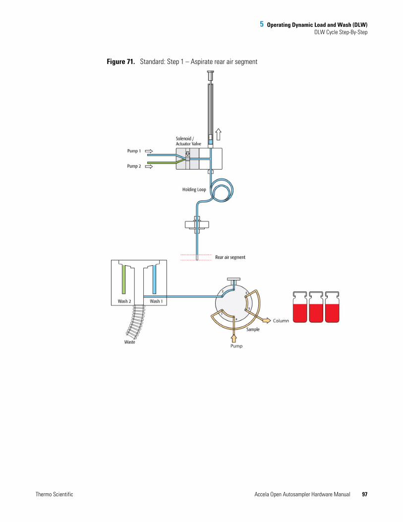
5 Operating Dynamic Load and Wash (DLW)DLW Cycle Step-By-Step
Thermo Scientific Accela Open Autosampler Hardware Manual 97
Figure 71. Standard: Step 1 – Aspirate rear air segment
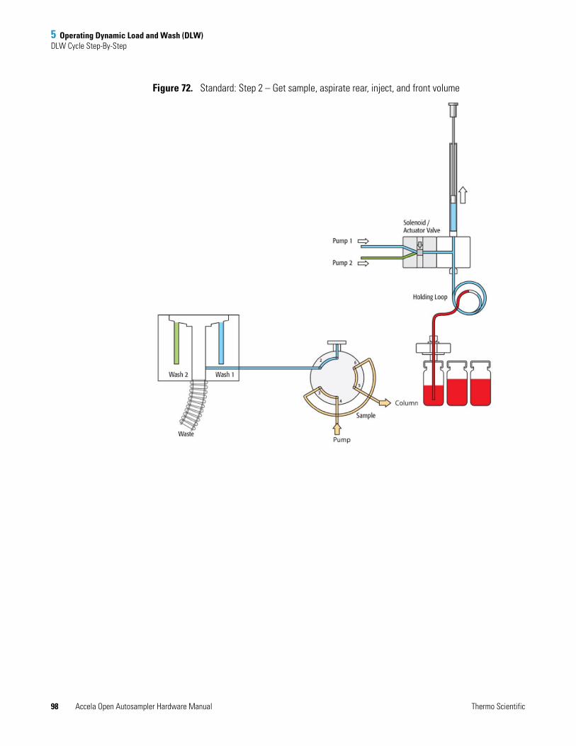
5 Operating Dynamic Load and Wash (DLW)DLW Cycle Step-By-Step
98 Accela Open Autosampler Hardware Manual Thermo Scientific
Figure 72. Standard: Step 2 – Get sample, aspirate rear, inject, and front volume

5 Operating Dynamic Load and Wash (DLW)DLW Cycle Step-By-Step
Thermo Scientific Accela Open Autosampler Hardware Manual 99
Figure 73. Standard: Steps 3 - 4 – Aspirate front air segment
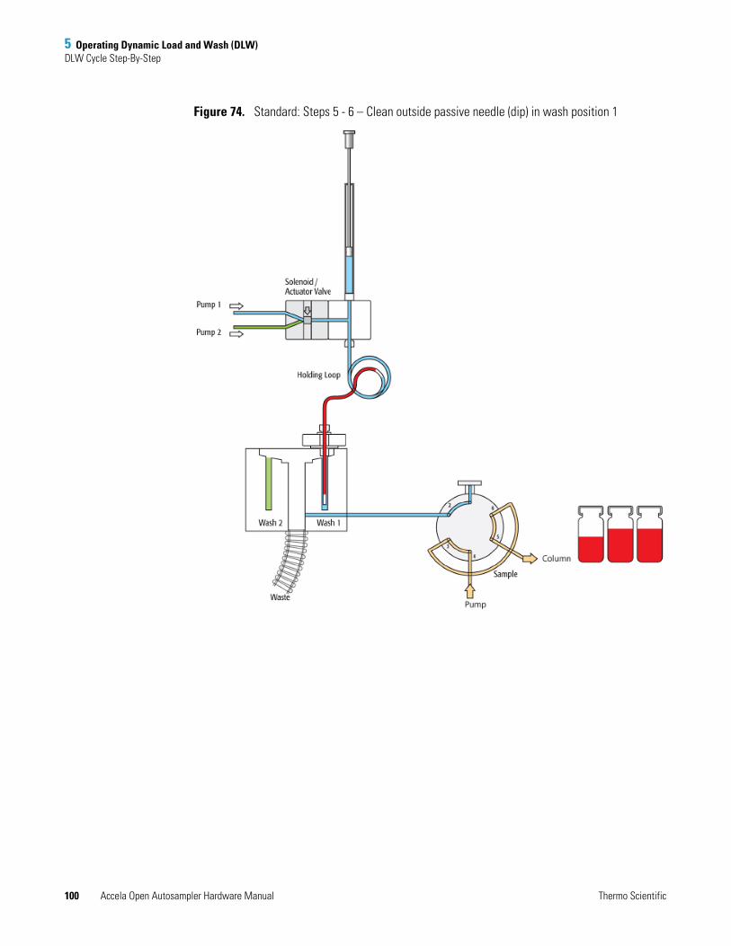
5 Operating Dynamic Load and Wash (DLW)DLW Cycle Step-By-Step
100 Accela Open Autosampler Hardware Manual Thermo Scientific
Figure 74. Standard: Steps 5 - 6 – Clean outside passive needle (dip) in wash position 1
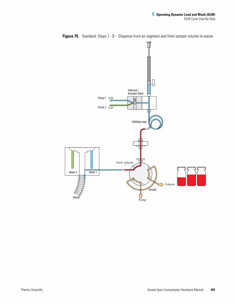
5 Operating Dynamic Load and Wash (DLW)DLW Cycle Step-By-Step
Thermo Scientific Accela Open Autosampler Hardware Manual 101
Figure 75. Standard: Steps 7 - 8 – Dispense front air segment and front sample volume to waste
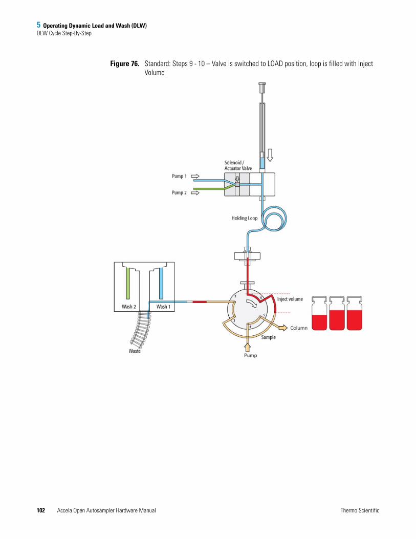
5 Operating Dynamic Load and Wash (DLW)DLW Cycle Step-By-Step
102 Accela Open Autosampler Hardware Manual Thermo Scientific
Figure 76. Standard: Steps 9 - 10 – Valve is switched to LOAD position, loop is filled with Inject Volume
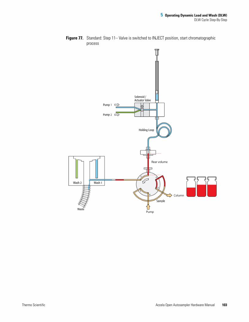
5 Operating Dynamic Load and Wash (DLW)DLW Cycle Step-By-Step
Thermo Scientific Accela Open Autosampler Hardware Manual 103
Figure 77. Standard: Step 11– Valve is switched to INJECT position, start chromatographic process
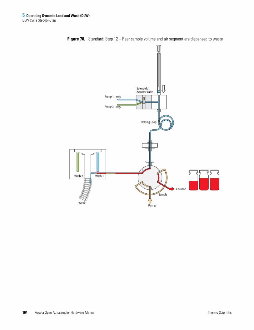
5 Operating Dynamic Load and Wash (DLW)DLW Cycle Step-By-Step
104 Accela Open Autosampler Hardware Manual Thermo Scientific
Figure 78. Standard: Step 12 – Rear sample volume and air segment are dispensed to waste
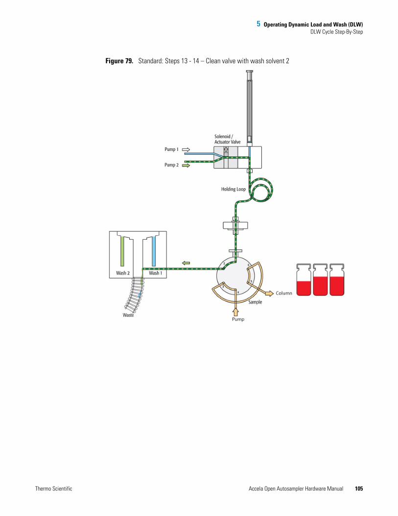
5 Operating Dynamic Load and Wash (DLW)DLW Cycle Step-By-Step
Thermo Scientific Accela Open Autosampler Hardware Manual 105
Figure 79. Standard: Steps 13 - 14 – Clean valve with wash solvent 2
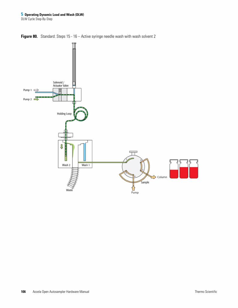
5 Operating Dynamic Load and Wash (DLW)DLW Cycle Step-By-Step
106 Accela Open Autosampler Hardware Manual Thermo Scientific
Figure 80. Standard: Steps 15 - 16 – Active syringe needle wash with wash solvent 2
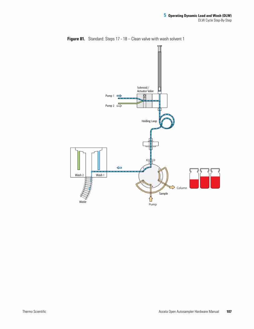
5 Operating Dynamic Load and Wash (DLW)DLW Cycle Step-By-Step
Thermo Scientific Accela Open Autosampler Hardware Manual 107
Figure 81. Standard: Steps 17 - 18 – Clean valve with wash solvent 1

5 Operating Dynamic Load and Wash (DLW)DLW Cycle Step-By-Step
108 Accela Open Autosampler Hardware Manual Thermo Scientific
Figure 82. Standard: Steps 19 - 20 – Wash active syringe needle with wash solvent 1
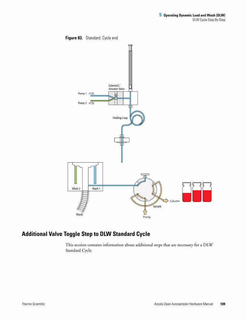
5 Operating Dynamic Load and Wash (DLW)DLW Cycle Step-By-Step
Thermo Scientific Accela Open Autosampler Hardware Manual 109
Figure 83. Standard: Cycle end
Additional Valve Toggle Step to DLW Standard Cycle
This section contains information about additional steps that are necessary for a DLW Standard Cycle.
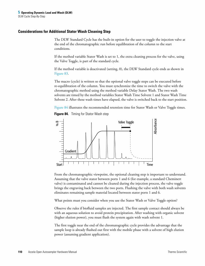
5 Operating Dynamic Load and Wash (DLW)DLW Cycle Step-By-Step
110 Accela Open Autosampler Hardware Manual Thermo Scientific
Considerations for Additional Stator Wash Cleaning Step
The DLW Standard Cycle has the built-in option for the user to toggle the injection valve at the end of the chromatographic run before equilibration of the column to the start conditions.
If the method variable Stator Wash is set to 1, the extra cleaning process for the valve, using the Valve Toggle, is part of the standard cycle.
If the method variable is deactivated (setting, 0), the DLW Standard cycle ends as shown in Figure 83.
The macro (cycle) is written so that the optional valve toggle steps can be executed before re-equilibration of the column. You must synchronize the time to switch the valve with the chromatographic method using the method variable Delay Stator Wash. The two wash solvents are timed by the method variables Stator Wash Time Solvent 1 and Stator Wash Time Solvent 2. After these wash times have elapsed, the valve is switched back to the start position.
Figure 84 illustrates the recommended retention time for Stator Wash or Valve Toggle times.
Figure 84. Timing for Stator Wash step
From the chromatographic viewpoint, the optional cleaning step is important to understand. Assuming that the valve stator between ports 1 and 6 (for example, a standard Cheminert valve) is contaminated and cannot be cleaned during the injection process, the valve toggle brings the engraving back between the two ports. Flushing the valve with both wash solvents eliminates remaining sample material located between stator ports 1 and 6.
What points must you consider when you use the Stator Wash or Valve Toggle option?
Observe the rules if biofluid samples are injected. The first sample contact should always be with an aqueous solution to avoid protein precipitation. After washing with organic solvent (higher elution power), you must flush the system again with wash solvent 1.
The first toggle near the end of the chromatographic cycle provides the advantage that the sample loop is already flushed out first with the mobile phase with a solvent of high elution power (assuming gradient application).
5 Operating Dynamic Load and Wash (DLW)DLW Cycle Step-By-Step
Thermo Scientific Accela Open Autosampler Hardware Manual 111
The second valve toggle time follows immediately after finishing the second solvent flush. You cannot program a second switching time. The waiting time for the second valve toggle should be long enough so that the entire system is flushed out by both wash solvents.
Consider the entire delay volume to determine the second valve switch. The DLW internal volumes are as follows:
Manifold, 90 μL Holding Loop,108 μL Syringe Needle Gauge 22, 6.7 μL Installed Injection Loop
Total delay volume: 205 μL + Loop content volume
Toggle the second valve (back to the starting condition) before the system equilibration time has started. The loop content is ideally a solvent of a low elution power when switched back.
If isocratic chromatography is applied, the remaining contaminants might be washed into the system and can build up higher background noise for the column, the detector, or both over a longer period of time.
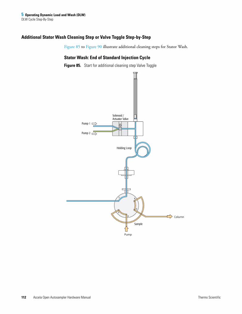
5 Operating Dynamic Load and Wash (DLW)DLW Cycle Step-By-Step
112 Accela Open Autosampler Hardware Manual Thermo Scientific
Additional Stator Wash Cleaning Step or Valve Toggle Step-by-Step
Figure 85 to Figure 90 illustrate additional cleaning steps for Stator Wash.
Stator Wash: End of Standard Injection Cycle
Figure 85. Start for additional cleaning step Valve Toggle
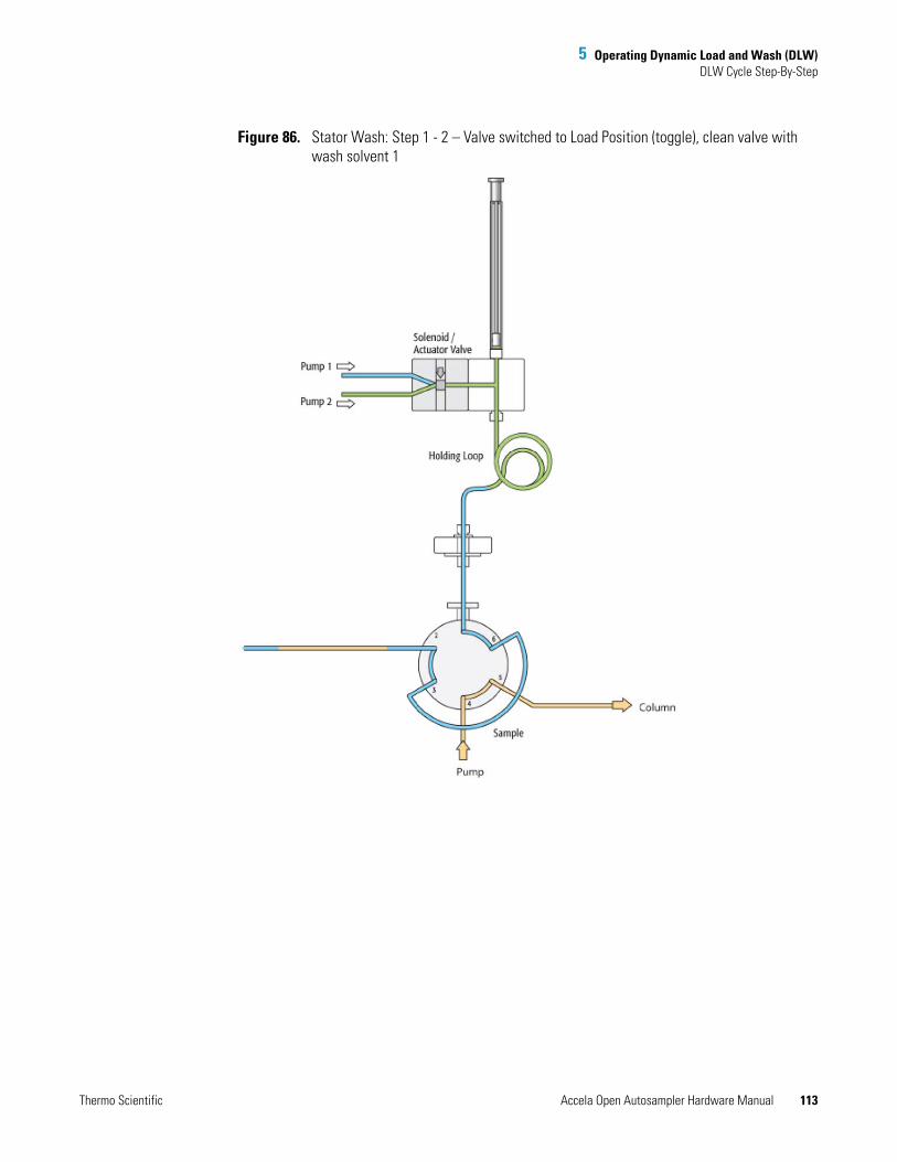
5 Operating Dynamic Load and Wash (DLW)DLW Cycle Step-By-Step
Thermo Scientific Accela Open Autosampler Hardware Manual 113
Figure 86. Stator Wash: Step 1 - 2 – Valve switched to Load Position (toggle), clean valve with wash solvent 1
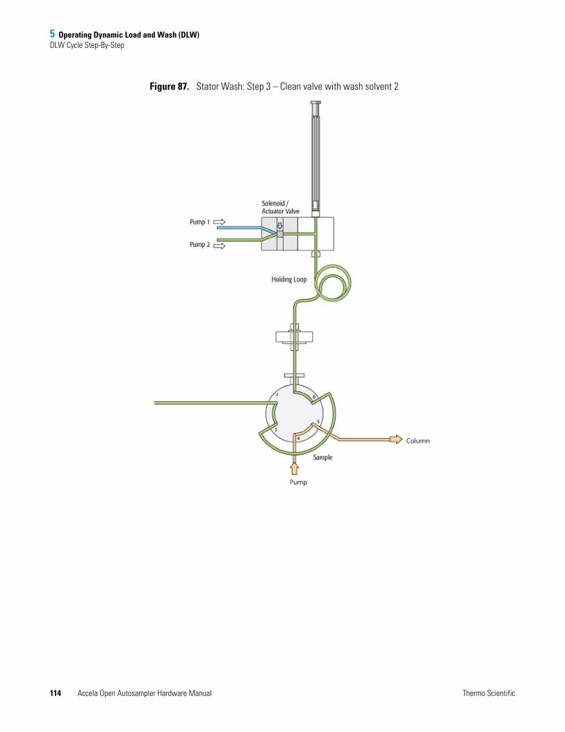
5 Operating Dynamic Load and Wash (DLW)DLW Cycle Step-By-Step
114 Accela Open Autosampler Hardware Manual Thermo Scientific
Figure 87. Stator Wash: Step 3 – Clean valve with wash solvent 2
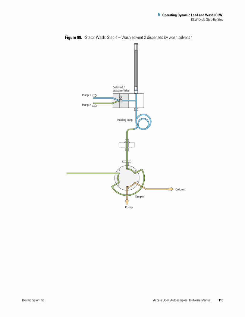
5 Operating Dynamic Load and Wash (DLW)DLW Cycle Step-By-Step
Thermo Scientific Accela Open Autosampler Hardware Manual 115
Figure 88. Stator Wash: Step 4 – Wash solvent 2 dispensed by wash solvent 1
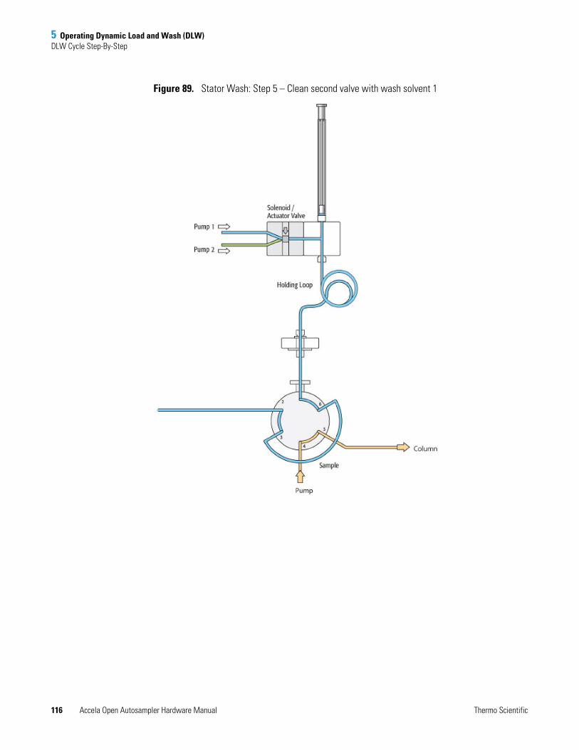
5 Operating Dynamic Load and Wash (DLW)DLW Cycle Step-By-Step
116 Accela Open Autosampler Hardware Manual Thermo Scientific
Figure 89. Stator Wash: Step 5 – Clean second valve with wash solvent 1
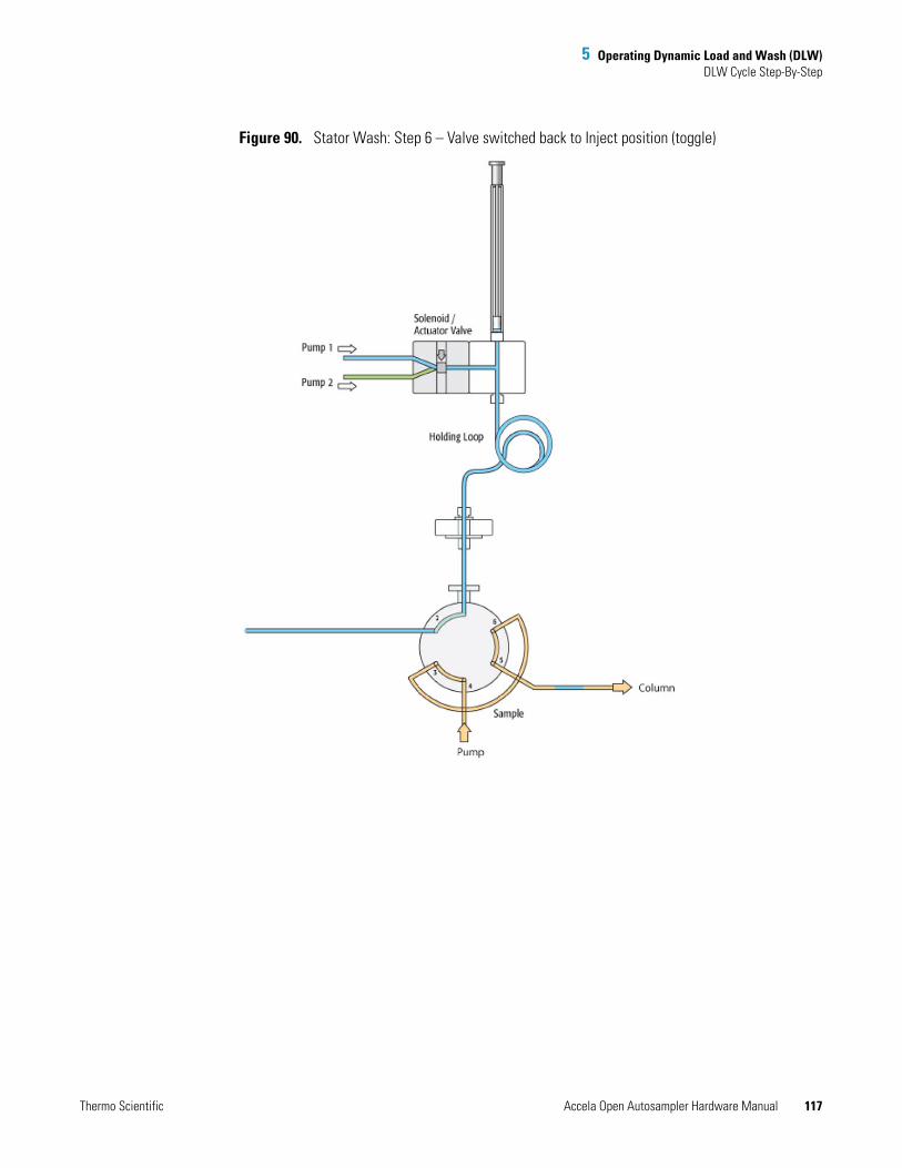
5 Operating Dynamic Load and Wash (DLW)DLW Cycle Step-By-Step
Thermo Scientific Accela Open Autosampler Hardware Manual 117
Figure 90. Stator Wash: Step 6 – Valve switched back to Inject position (toggle)
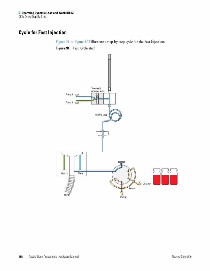
5 Operating Dynamic Load and Wash (DLW)DLW Cycle Step-By-Step
118 Accela Open Autosampler Hardware Manual Thermo Scientific
Cycle for Fast Injection
Figure 91 to Figure 102 illustrate a step-by-step cycle for the Fast Injection.
Figure 91. Fast: Cycle start
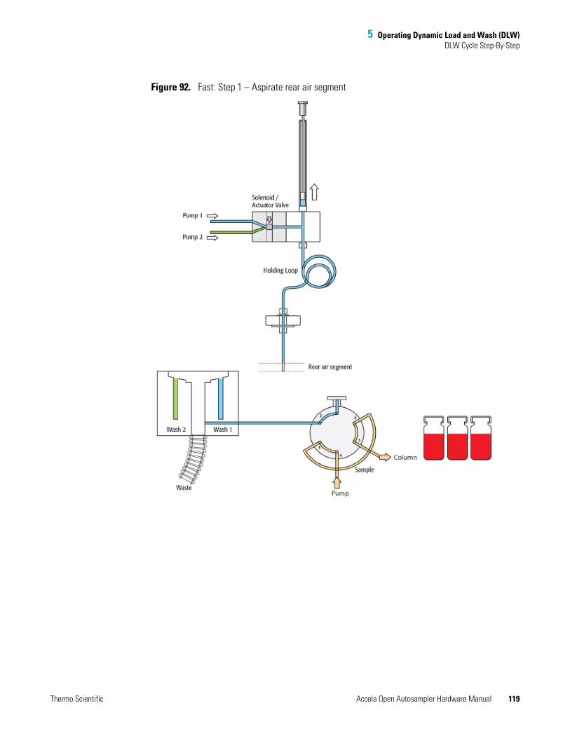
5 Operating Dynamic Load and Wash (DLW)DLW Cycle Step-By-Step
Thermo Scientific Accela Open Autosampler Hardware Manual 119
Figure 92. Fast: Step 1 – Aspirate rear air segment

5 Operating Dynamic Load and Wash (DLW)DLW Cycle Step-By-Step
120 Accela Open Autosampler Hardware Manual Thermo Scientific
Figure 93. Fast: Step 2 – Get sample, aspirate rear, inject, and front volume
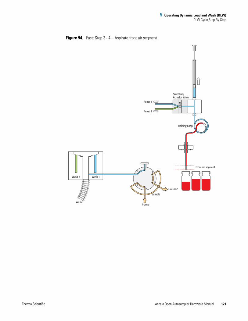
5 Operating Dynamic Load and Wash (DLW)DLW Cycle Step-By-Step
Thermo Scientific Accela Open Autosampler Hardware Manual 121
Figure 94. Fast: Step 3 - 4 – Aspirate front air segment
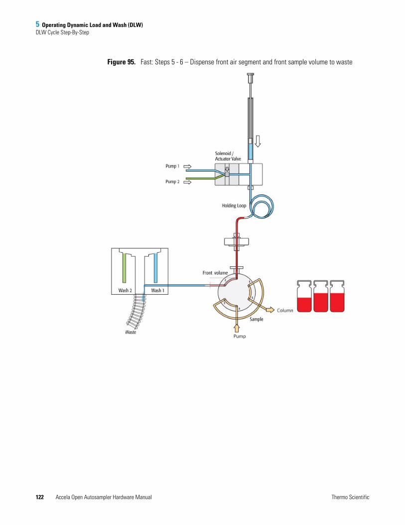
5 Operating Dynamic Load and Wash (DLW)DLW Cycle Step-By-Step
122 Accela Open Autosampler Hardware Manual Thermo Scientific
Figure 95. Fast: Steps 5 - 6 – Dispense front air segment and front sample volume to waste
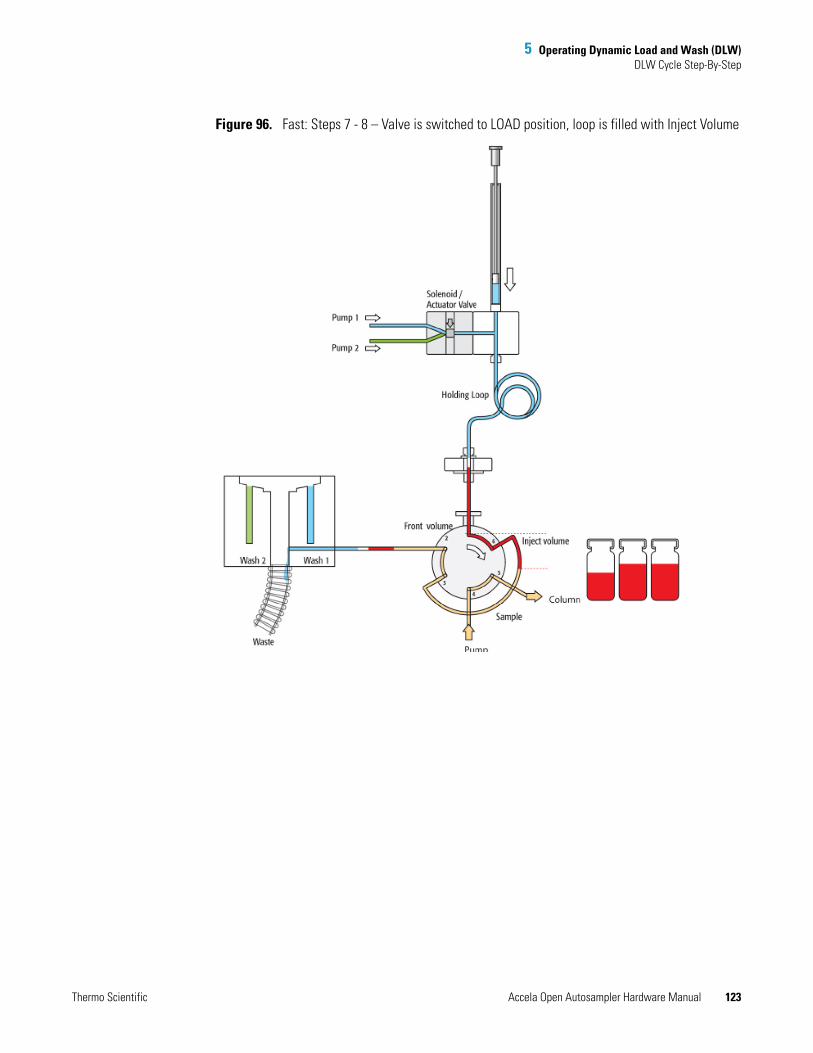
5 Operating Dynamic Load and Wash (DLW)DLW Cycle Step-By-Step
Thermo Scientific Accela Open Autosampler Hardware Manual 123
Figure 96. Fast: Steps 7 - 8 – Valve is switched to LOAD position, loop is filled with Inject Volume
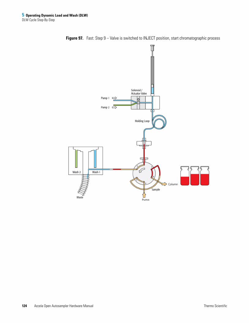
5 Operating Dynamic Load and Wash (DLW)DLW Cycle Step-By-Step
124 Accela Open Autosampler Hardware Manual Thermo Scientific
Figure 97. Fast: Step 9 – Valve is switched to INJECT position, start chromatographic process
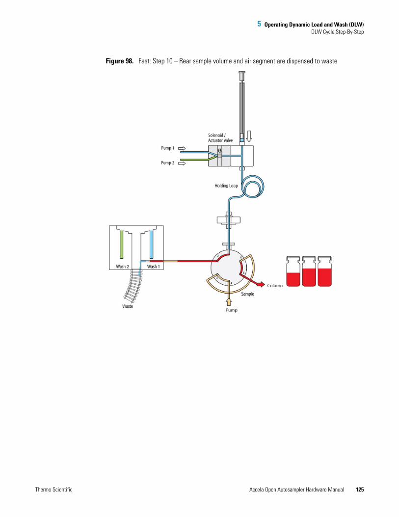
5 Operating Dynamic Load and Wash (DLW)DLW Cycle Step-By-Step
Thermo Scientific Accela Open Autosampler Hardware Manual 125
Figure 98. Fast: Step 10 – Rear sample volume and air segment are dispensed to waste
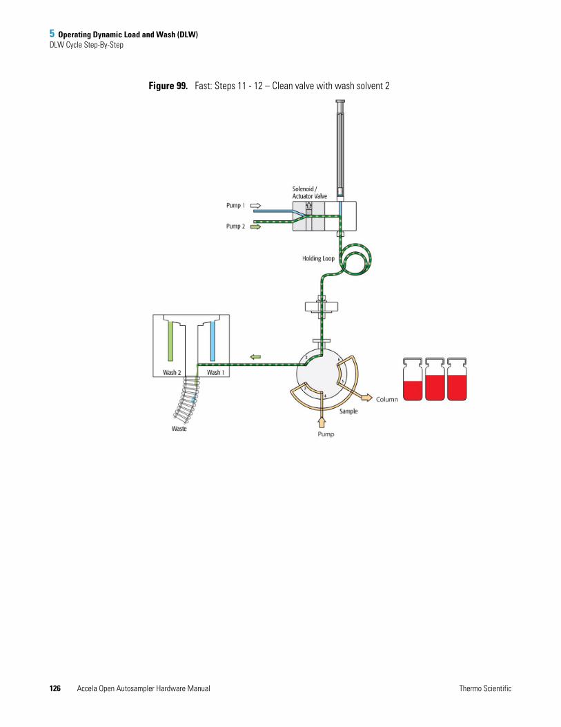
5 Operating Dynamic Load and Wash (DLW)DLW Cycle Step-By-Step
126 Accela Open Autosampler Hardware Manual Thermo Scientific
Figure 99. Fast: Steps 11 - 12 – Clean valve with wash solvent 2
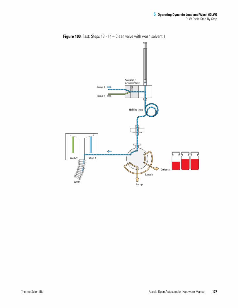
5 Operating Dynamic Load and Wash (DLW)DLW Cycle Step-By-Step
Thermo Scientific Accela Open Autosampler Hardware Manual 127
Figure 100. Fast: Steps 13 - 14 – Clean valve with wash solvent 1
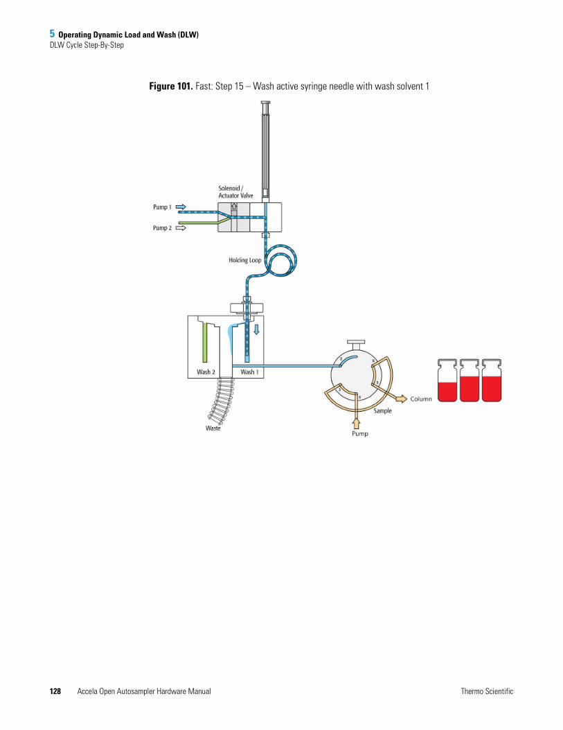
5 Operating Dynamic Load and Wash (DLW)DLW Cycle Step-By-Step
128 Accela Open Autosampler Hardware Manual Thermo Scientific
Figure 101. Fast: Step 15 – Wash active syringe needle with wash solvent 1
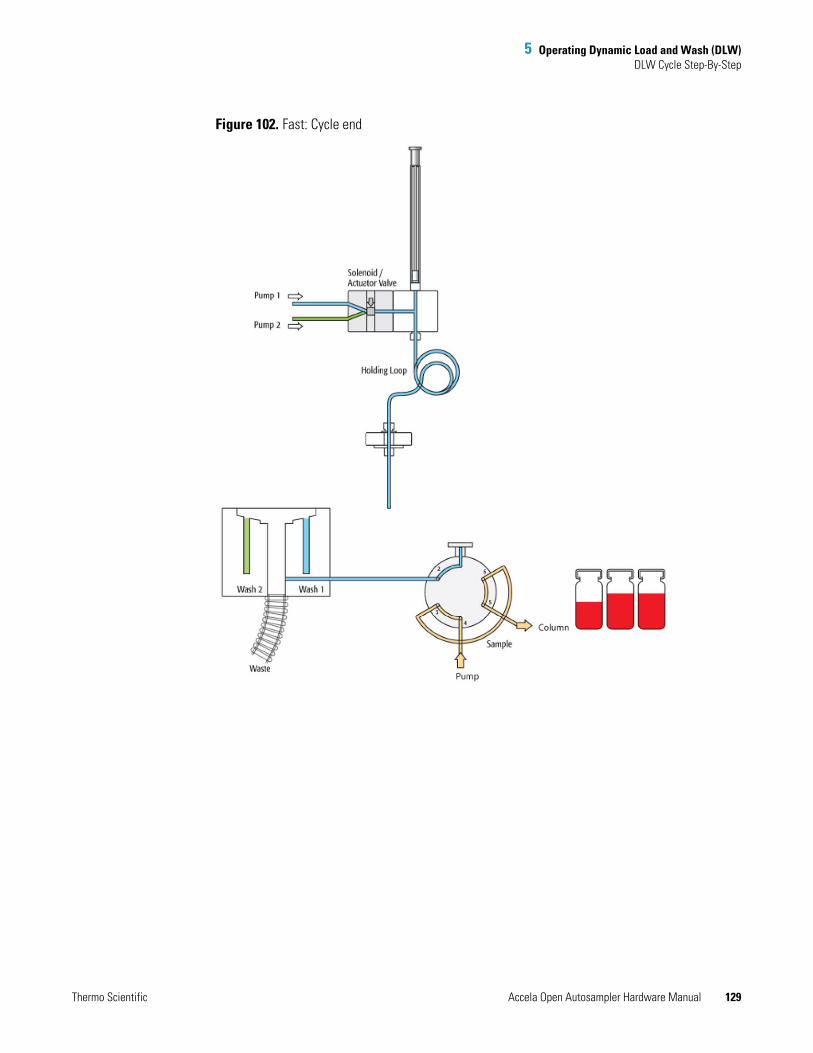
5 Operating Dynamic Load and Wash (DLW)DLW Cycle Step-By-Step
Thermo Scientific Accela Open Autosampler Hardware Manual 129
Figure 102. Fast: Cycle end

Thermo Scientific Accela Open Autosampler Hardware Manual 131
6
Operating the Temperature Controllable Stack Coolers
This chapter describes how to set the temperature, temperature control, and alarm. It also discusses temperature stability and condensation build-up.
Temperature Setting, Control, and AlarmThis section contains information about the temperature setting, temperature control, and temperature alarm.
Temperature Setting
Turning the power on (|) at the power supply module puts the control unit into self-check mode. The set value for the temperature appears after a few seconds.
The stack/tray cooler temperature is preset by the factory to 10 °C.
To change the value
1. Press P briefly (less than two seconds) until SP1 appears.
2. Use the increment/decrement keys to select the desired value.
3. Press P again.
Contents
• Temperature Setting, Control, and Alarm
• Temperature Stability
• Condensation Build-Up
6 Operating the Temperature Controllable Stack CoolersTemperature Setting, Control, and Alarm
132 Accela Open Autosampler Hardware Manual Thermo Scientific
Factory programming blocks the U key.
There are indicators below the display digits that show which relay is in use, OUT1 or OUT2. The arrows indicate if the unit is heating or cooling.
heating temperature within range of set point cooling
Temperature Control
As described in the Specifications section, the cooling/heating capacity of a temperature control device based on the Peltier technique is always related to room temperature. Only a limited maximum temperature difference from ambient temperature can be achieved. PAL stack/tray cooler modules should reach a minimum difference of 14 °C (ΔT).
The controller provides the following temperature setting range:
• Stack cooler: +1 to 45 °C
• Tray cooler: +1 to 70 °C
This wider control range, which is greater than the specification limits (+4 to 40 °C and +4 to 70 °C, respectively), provides cooling or heating when the ambient temperature is too high or too low to easily reach the desired temperature. Heating to a higher temperature could be important for metabolism or kinetics studies at the human body temperature level of 37 °C.
The cooling option is usually necessary to protect the sample from ambient temperature during the analytical run time. Stack/tray cooler devices are rarely used to store a sample at a given temperature for a longer time period.
The measured and displayed temperature represents the temperature in the compartment and not in the sample liquid. To check the temperature control, an independent temperature probe is inserted from the front by removing one plastic screw from the front cover. Position the probe in the middle of the drawer where the tray separator projects up. Tape the probe to the metal plate of the drawer.
To reach +4 °C in the analytical solution, program a set value lower than +4 °C. The material used for the sample may be glass, polypropylene, polyethylene, or similar polymer products. All of these have excellent insulating properties.
Note Pressing the P button for two seconds or longer will access the programming level. You can access values, such as OPEr, ConF, OFF, rEG, tune and OPLO, in the menu by selecting the increment/decrement keys. The user is blocked from all of these menu items. Leaving the unit untouched for approximately two minutes returns the display to the current temperature reading information. Turning the device off/on reinstates the temperature display.
6 Operating the Temperature Controllable Stack CoolersTemperature Stability
Thermo Scientific Accela Open Autosampler Hardware Manual 133
If the sample has to be cooled as low as +4 °C, cool the sample tray first in a refrigerator before the tray is placed into a stack/tray cooler module. This shortens cool-down time considerably.
Temperature Alarm
An internal alarm point of 55 °C protects the upper limit of a stack cooler module; it is 72 °C for a tray cooler. Reaching this point in a single fault situation causes the temperature control unit to automatically force cooling to the fullest extent possible. (The alarm is not audible.) At the same time a corresponding Error message is displayed. For explanations of these messages, see “Cooled Stack Power Supply Error Messages” on page 141.
A fuse to prevent overheating is built in for unattended automated runs.
The Peltier element turns off automatically at +72 ± 5 °C.
Only an authorized representative of Thermo Fisher Scientific can replace a damaged over-temperature fuse.
In case of error, do the following systematically:
1. Check the corresponding error message (see “Cooled Stack Power Supply Error Messages” on page 141).
2. Verify whether the appropriate power supply is being used for the stack cooler and tray cooler.
3. Turn off the power supply, wait a few minutes, and turn it on again.
Ensure that the alarm is off. If the alarm is still on, observe the corresponding error message.
Temperature StabilityThe stack/tray cooler is basically a thermostatted sample tray that keeps the analytical sample below or above ambient temperature.
Thermo Fisher Scientific recommends the following guidelines:
• Switch on the stack/tray cooler at least 30 minutes before the analytical routine run is to be started at +10 °C or 75 minutes, if operated at +4 °C.
• For high-throughput analysis–typical cycle time of 60 seconds or less per analysis–leave the drawers open between injections.
• For longer cycle times, use the Accela Open Autosampler option to close the drawer after each sampling.
You can change the Restore mode to keep the drawer open or closed during a run
6 Operating the Temperature Controllable Stack CoolersCondensation Build-Up
134 Accela Open Autosampler Hardware Manual Thermo Scientific
To change the Restore mode
Complete the following steps starting at the top-level command from the control terminal:
a. Choose Menu > F3-Setup > Objects > Trayholders > Cstack >Restore Mode.
b. Change the default value from Sample to Auto.
c. Press HOME.
Condensation Build-UpThis section contains information about condensation build-up in in stack coolers and tray coolers.
Condensation Build-Up in Accela Open Autosampler Stack Coolers
Condensation build-up is directly related to the temperature and relative humidity/ temperature in ambient air (dew point). Long-term tests showed very little build-up of condensation in an environment of relative humidity up to 60 % and 22 ± 2 °C ambient temperature.
Condensation at the back of the compartments is channeled to the drain outlet labeled Condensation Drain at the lower back portion of the stack cooler. The outlet is plugged with a paper filter. This helps to evaporate the collected water in the drain line using the excess heat from the Peltier element. A drain line from the outlet to a reservoir bottle is not necessary under normal conditions.
If you operate the stack cooler under severe conditions, you can use a flow of dry and clean (oil-free) air or nitrogen to dry the compartments continually. Connect the corresponding gas line to the Swagelok fitting (1/8 in.) at the back of the stack cooler DW labeled Flush Gas. A flow of approximately 300 to 400 mL/min is required to keep the compartments moisture-free.
If acidic vapor phase is anticipated due to the application, use the same gas line connection to flush a stream of inert gas, such as nitrogen or helium, into the compartments. A stream of a few mL/min can help to prevent corrosion of the rolls.
Note The preset mode for the stack cooler in combination with the PAL System closes the drawers after sampling during an analytical run.
CAUTION If a flush gas is used as described below, you are responsible for ensuring that a two-stage safety pressure regulator device is installed between the gas supply and the stack cooler.
Do not use any flammable or explosive gas such as hydrogen.
6 Operating the Temperature Controllable Stack CoolersCondensation Build-Up
Thermo Scientific Accela Open Autosampler Hardware Manual 135
Thermo Fisher Scientific recommends checking regularly for condensation build-up. It is good practice to clean the inside of the stack cooler when changing the analytical samples, dry out the stack cooler at ambient temperature at regular intervals, and open the drawers 1 cm to 5 cm (0.5 in. to 2.0 in.) for air circulation. The compartment drying frequency depends greatly on surrounding conditions.
Condensation Build-Up in PAL Tray Coolers
Condensation build-up is directly related to the temperature and relative humidity/ temperature in ambient air (dew point). Long term tests showed little build-up of condensation in an environment of relative humidity up to 60 percent and 22 ± 2 °C ambient temperature.
A built-in drain line, as installed in stack coolers, is not provided in a tray cooler.
It is also good practice to install the Plexiglass lid whenever possible to avoid condensation build-up. You might not be able to install a lid for certain applications, for example, if a vial has to be transported to an Agitator or a Barcode Reader. In certain situations, the height of the vial is the limiting factor for installing a lid. Operating a tray cooler under less than optimal conditions requires some on-site improvisation. A simple foil or lid with cut-outs for the vials will limit condensation build-up dramatically.
Thermo Fisher Scientific recommends checking regularly for condensation build-up. Clean the inside of the tray cooler when changing the analytical samples, and dry out the tray cooler at ambient temperature at regular intervals.
Note For certain applications, a change from a tray cooler to Stack 2DW Cooler might be indicated. As long as deep well, microtitier plates, or 2 mL vials (TrayType VT54) are being handled, this change is positive with respect to condensation build-up. It would also double the capacity of the trays.

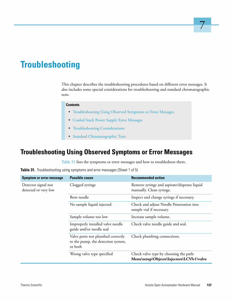
Thermo Scientific Accela Open Autosampler Hardware Manual 137
7
Troubleshooting
This chapter describes the troubleshooting procedures based on different error messages. It also includes some special considerations for troubleshooting and standard chromatographic tests.
Troubleshooting Using Observed Symptoms or Error MessagesTable 31 lists the symptoms or error messages and how to troubleshoot them.
Contents
• Troubleshooting Using Observed Symptoms or Error Messages
• Cooled Stack Power Supply Error Messages
• Troubleshooting Considerations
• Standard Chromatographic Tests
Table 31. Troubleshooting using symptoms and error messages (Sheet 1 of 5)
Symptom or error message Possible cause Recommended action
Detector signal not detected or very low
Clogged syringe Remove syringe and aspirate/dispense liquid manually. Clean syringe.
Bent needle Inspect and change syringe if necessary.
No sample liquid injected Check and adjust Needle Penetration into sample vial if necessary.
Sample volume too low Increase sample volume.
Improperly installed valve needle guide and/or needle seal
Check valve needle guide and seal.
Valve ports not plumbed correctly to the pump, the detection system, or both
Check plumbing connections.
Wrong valve type specified Check valve type by choosing the path: Menu\setup\Objects\Injectors\LCVlv1\valve
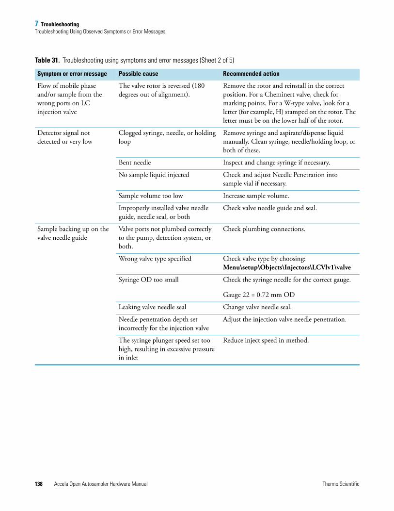
7 TroubleshootingTroubleshooting Using Observed Symptoms or Error Messages
138 Accela Open Autosampler Hardware Manual Thermo Scientific
Flow of mobile phase and/or sample from the wrong ports on LC injection valve
The valve rotor is reversed (180 degrees out of alignment).
Remove the rotor and reinstall in the correct position. For a Cheminert valve, check for marking points. For a W-type valve, look for a letter (for example, H) stamped on the rotor. The letter must be on the lower half of the rotor.
Detector signal not detected or very low
Clogged syringe, needle, or holding loop
Remove syringe and aspirate/dispense liquid manually. Clean syringe, needle/holding loop, or both of these.
Bent needle Inspect and change syringe if necessary.
No sample liquid injected Check and adjust Needle Penetration into sample vial if necessary.
Sample volume too low Increase sample volume.
Improperly installed valve needle guide, needle seal, or both
Check valve needle guide and seal.
Sample backing up on the valve needle guide
Valve ports not plumbed correctly to the pump, detection system, or both.
Check plumbing connections.
Wrong valve type specified Check valve type by choosing: Menu\setup\Objects\Injectors\LCVlv1\valve
Syringe OD too small Check the syringe needle for the correct gauge.
Gauge 22 = 0.72 mm OD
Leaking valve needle seal Change valve needle seal.
Needle penetration depth set incorrectly for the injection valve
Adjust the injection valve needle penetration.
The syringe plunger speed set too high, resulting in excessive pressure in inlet
Reduce inject speed in method.
Table 31. Troubleshooting using symptoms and error messages (Sheet 2 of 5)
Symptom or error message Possible cause Recommended action
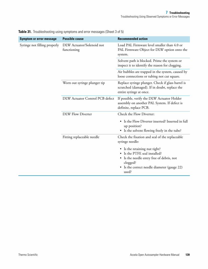
7 TroubleshootingTroubleshooting Using Observed Symptoms or Error Messages
Thermo Scientific Accela Open Autosampler Hardware Manual 139
Syringe not filling properly DLW Actuator/Solenoid not functioning
Load PAL Firmware level smaller than 4.0 or PAL Firmware Object for DLW option onto the system.
Solvent path is blocked. Prime the system or inspect it to identify the reason for clogging.
Air bubbles are trapped in the system, caused by loose connections or tubing not cut square.
Worn out syringe plunger tip Replace syringe plunger. Check if glass barrel is scratched (damaged). If in doubt, replace the entire syringe at once.
DLW Actuator Control PCB defect If possible, verify the DLW Actuator Holder assembly on another PAL System. If defect is definite, replace PCB.
DLW Flow Diverter Check the Flow Diverter:
• Is the Flow Diverter inserted? Inserted in full up position?
• Is the solvent flowing freely in the tube?
Fitting replaceable needle Check the fixation and seal of the replaceable syringe needle:
• Is the retaining nut tight?• Is the PTFE seal installed?• Is the needle entry free of debris, not
clogged?• Is the correct needle diameter (gauge 22)
used?
Table 31. Troubleshooting using symptoms and error messages (Sheet 3 of 5)
Symptom or error message Possible cause Recommended action
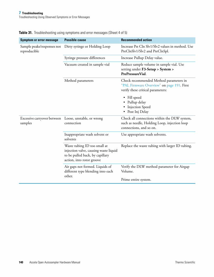
7 TroubleshootingTroubleshooting Using Observed Symptoms or Error Messages
140 Accela Open Autosampler Hardware Manual Thermo Scientific
Sample peaks/responses not reproducible
Dirty syringe or Holding Loop Increase Pst Cln Slv1/Slv2 values in method. Use PreClnSlv1/Slv2 and PreClnSpl.
Syringe pressure differences Increase Pullup Delay value.
Vacuum created in sample vial Reduce sample volume in sample vial. Use setting under F3-Setup > System > PrePressureVial.
Method parameters Check recommended Method parameters in “PAL Firmware Overview” on page 191. First verify these critical parameters:
• Fill speed• Pullup delay• Injection Speed• Post Inj Delay
Excessive carryover between samples
Loose, unstable, or wrong connection
Check all connections within the DLW system, such as needle, Holding Loop, injection loop connections, and so on.
Inappropriate wash solvent or solvents
Use appropriate wash solvents.
Waste tubing ID too small at injection valve, causing waste liquid to be pulled back, by capillary action, into rotor groove
Replace the waste tubing with larger ID tubing.
Air gaps not formed. Liquids of different type blending into each other.
Verify the DLW method parameter for Airgap Volume.
Prime entire system.
Table 31. Troubleshooting using symptoms and error messages (Sheet 4 of 5)
Symptom or error message Possible cause Recommended action
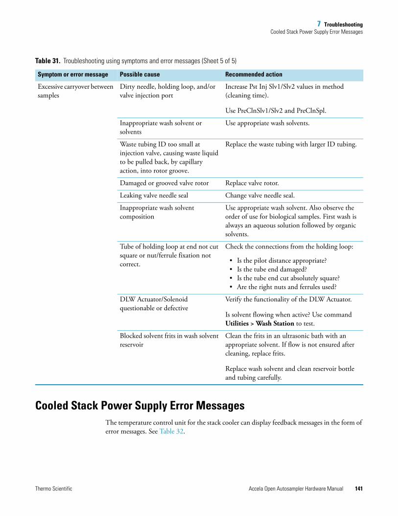
7 TroubleshootingCooled Stack Power Supply Error Messages
Thermo Scientific Accela Open Autosampler Hardware Manual 141
Cooled Stack Power Supply Error MessagesThe temperature control unit for the stack cooler can display feedback messages in the form of error messages. See Table 32.
Excessive carryover between samples
Dirty needle, holding loop, and/or valve injection port
Increase Pst Inj Slv1/Slv2 values in method (cleaning time).
Use PreClnSlv1/Slv2 and PreClnSpl.
Inappropriate wash solvent or solvents
Use appropriate wash solvents.
Waste tubing ID too small at injection valve, causing waste liquid to be pulled back, by capillary action, into rotor groove.
Replace the waste tubing with larger ID tubing.
Damaged or grooved valve rotor Replace valve rotor.
Leaking valve needle seal Change valve needle seal.
Inappropriate wash solvent composition
Use appropriate wash solvent. Also observe the order of use for biological samples. First wash is always an aqueous solution followed by organic solvents.
Tube of holding loop at end not cut square or nut/ferrule fixation not correct.
Check the connections from the holding loop:
• Is the pilot distance appropriate? • Is the tube end damaged?• Is the tube end cut absolutely square?• Are the right nuts and ferrules used?
DLW Actuator/Solenoid questionable or defective
Verify the functionality of the DLW Actuator.
Is solvent flowing when active? Use command Utilities > Wash Station to test.
Blocked solvent frits in wash solvent reservoir
Clean the frits in an ultrasonic bath with an appropriate solvent. If flow is not ensured after cleaning, replace frits.
Replace wash solvent and clean reservoir bottle and tubing carefully.
Table 31. Troubleshooting using symptoms and error messages (Sheet 5 of 5)
Symptom or error message Possible cause Recommended action
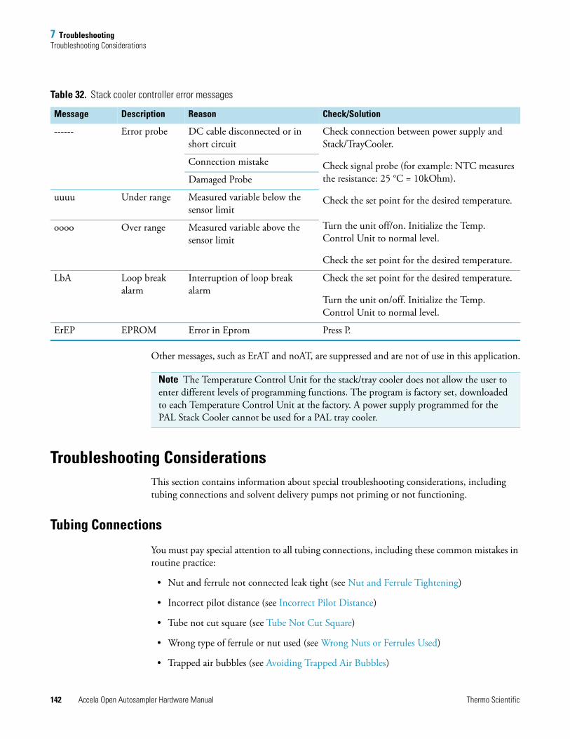
7 TroubleshootingTroubleshooting Considerations
142 Accela Open Autosampler Hardware Manual Thermo Scientific
Other messages, such as ErAT and noAT, are suppressed and are not of use in this application.
Troubleshooting ConsiderationsThis section contains information about special troubleshooting considerations, including tubing connections and solvent delivery pumps not priming or not functioning.
Tubing Connections
You must pay special attention to all tubing connections, including these common mistakes in routine practice:
• Nut and ferrule not connected leak tight (see Nut and Ferrule Tightening)
• Incorrect pilot distance (see Incorrect Pilot Distance)
• Tube not cut square (see Tube Not Cut Square)
• Wrong type of ferrule or nut used (see Wrong Nuts or Ferrules Used)
• Trapped air bubbles (see Avoiding Trapped Air Bubbles)
Table 32. Stack cooler controller error messages
Message Description Reason Check/Solution
------ Error probe DC cable disconnected or in short circuit
Check connection between power supply and Stack/TrayCooler.
Check signal probe (for example: NTC measures the resistance: 25 °C = 10kOhm).
Check the set point for the desired temperature.
Turn the unit off/on. Initialize the Temp. Control Unit to normal level.
Check the set point for the desired temperature.
Connection mistake
Damaged Probe
uuuu Under range Measured variable below the sensor limit
oooo Over range Measured variable above the sensor limit
LbA Loop break alarm
Interruption of loop break alarm
Check the set point for the desired temperature.
Turn the unit on/off. Initialize the Temp. Control Unit to normal level.
ErEP EPROM Error in Eprom Press P.
Note The Temperature Control Unit for the stack/tray cooler does not allow the user to enter different levels of programming functions. The program is factory set, downloaded to each Temperature Control Unit at the factory. A power supply programmed for the PAL Stack Cooler cannot be used for a PAL tray cooler.
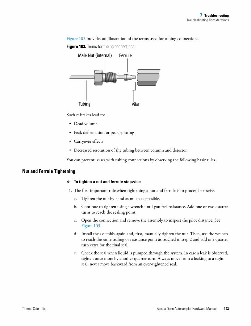
7 TroubleshootingTroubleshooting Considerations
Thermo Scientific Accela Open Autosampler Hardware Manual 143
Figure 103 provides an illustration of the terms used for tubing connections.
Figure 103. Terms for tubing connections
Such mistakes lead to:
• Dead volume
• Peak deformation or peak splitting
• Carryover effects
• Decreased resolution of the tubing between column and detector
You can prevent issues with tubing connections by observing the following basic rules.
Nut and Ferrule Tightening
To tighten a nut and ferrule stepwise
1. The first important rule when tightening a nut and ferrule is to proceed stepwise.
a. Tighten the nut by hand as much as possible.
b. Continue to tighten using a wrench until you feel resistance. Add one or two quarter turns to reach the sealing point.
c. Open the connection and remove the assembly to inspect the pilot distance. See Figure 103.
d. Install the assembly again and, first, manually tighten the nut. Then, use the wrench to reach the same sealing or resistance point as reached in step 2 and add one quarter turn extra for the final seal.
e. Check the seal when liquid is pumped through the system. In case a leak is observed, tighten once more by another quarter turn. Always move from a leaking to a tight seal; never move backward from an over-tightened seal.
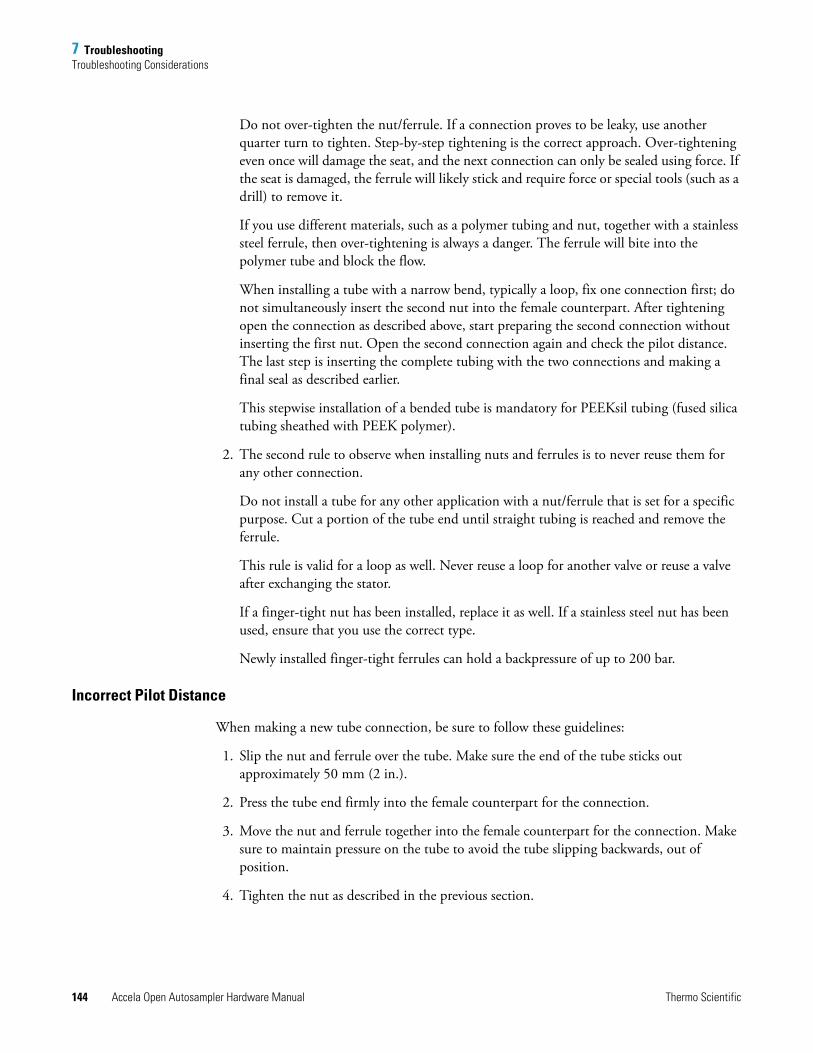
7 TroubleshootingTroubleshooting Considerations
144 Accela Open Autosampler Hardware Manual Thermo Scientific
Do not over-tighten the nut/ferrule. If a connection proves to be leaky, use another quarter turn to tighten. Step-by-step tightening is the correct approach. Over-tightening even once will damage the seat, and the next connection can only be sealed using force. If the seat is damaged, the ferrule will likely stick and require force or special tools (such as a drill) to remove it.
If you use different materials, such as a polymer tubing and nut, together with a stainless steel ferrule, then over-tightening is always a danger. The ferrule will bite into the polymer tube and block the flow.
When installing a tube with a narrow bend, typically a loop, fix one connection first; do not simultaneously insert the second nut into the female counterpart. After tightening open the connection as described above, start preparing the second connection without inserting the first nut. Open the second connection again and check the pilot distance. The last step is inserting the complete tubing with the two connections and making a final seal as described earlier.
This stepwise installation of a bended tube is mandatory for PEEKsil tubing (fused silica tubing sheathed with PEEK polymer).
2. The second rule to observe when installing nuts and ferrules is to never reuse them for any other connection.
Do not install a tube for any other application with a nut/ferrule that is set for a specific purpose. Cut a portion of the tube end until straight tubing is reached and remove the ferrule.
This rule is valid for a loop as well. Never reuse a loop for another valve or reuse a valve after exchanging the stator.
If a finger-tight nut has been installed, replace it as well. If a stainless steel nut has been used, ensure that you use the correct type.
Newly installed finger-tight ferrules can hold a backpressure of up to 200 bar.
Incorrect Pilot Distance
When making a new tube connection, be sure to follow these guidelines:
1. Slip the nut and ferrule over the tube. Make sure the end of the tube sticks out approximately 50 mm (2 in.).
2. Press the tube end firmly into the female counterpart for the connection.
3. Move the nut and ferrule together into the female counterpart for the connection. Make sure to maintain pressure on the tube to avoid the tube slipping backwards, out of position.
4. Tighten the nut as described in the previous section.
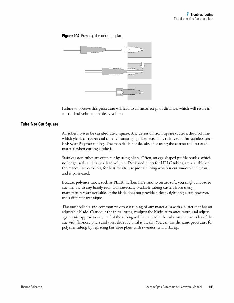
7 TroubleshootingTroubleshooting Considerations
Thermo Scientific Accela Open Autosampler Hardware Manual 145
Figure 104. Pressing the tube into place
Failure to observe this procedure will lead to an incorrect pilot distance, which will result in actual dead volume, not delay volume.
Tube Not Cut Square
All tubes have to be cut absolutely square. Any deviation from square causes a dead volume which yields carryover and other chromatographic effects. This rule is valid for stainless steel, PEEK, or Polymer tubing. The material is not decisive, but using the correct tool for each material when cutting a tube is.
Stainless steel tubes are often cut by using pliers. Often, an egg-shaped profile results, which no longer seals and causes dead volume. Dedicated pliers for HPLC tubing are available on the market; nevertheless, for best results, use precut tubing which is cut smooth and clean, and is passivated.
Because polymer tubes, such as PEEK, Teflon, PFA, and so on are soft, you might choose to cut them with any handy tool. Commercially available tubing cutters from many manufacturers are available. If the blade does not provide a clean, right-angle cut, however, use a different technique.
The most reliable and common way to cut tubing of any material is with a cutter that has an adjustable blade. Carry out the initial turns, readjust the blade, turn once more, and adjust again until approximately half of the tubing wall is cut. Hold the tube on the two sides of the cut with flat-nose pliers and twist the tube until it breaks. You can use the same procedure for polymer tubing by replacing flat-nose pliers with tweezers with a flat tip.
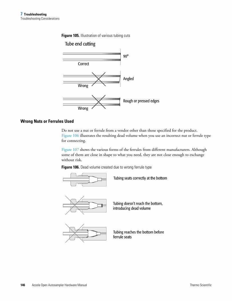
7 TroubleshootingTroubleshooting Considerations
146 Accela Open Autosampler Hardware Manual Thermo Scientific
Figure 105. Illustration of various tubing cuts
Wrong Nuts or Ferrules Used
Do not use a nut or ferrule from a vendor other than those specified for the product. Figure 106 illustrates the resulting dead volume when you use an incorrect nut or ferrule type for connecting.
Figure 107 shows the various forms of the ferrules from different manufacturers. Although some of them are close in shape to what you need, they are not close enough to exchange without risk.
Figure 106. Dead volume created due to wrong ferrule type
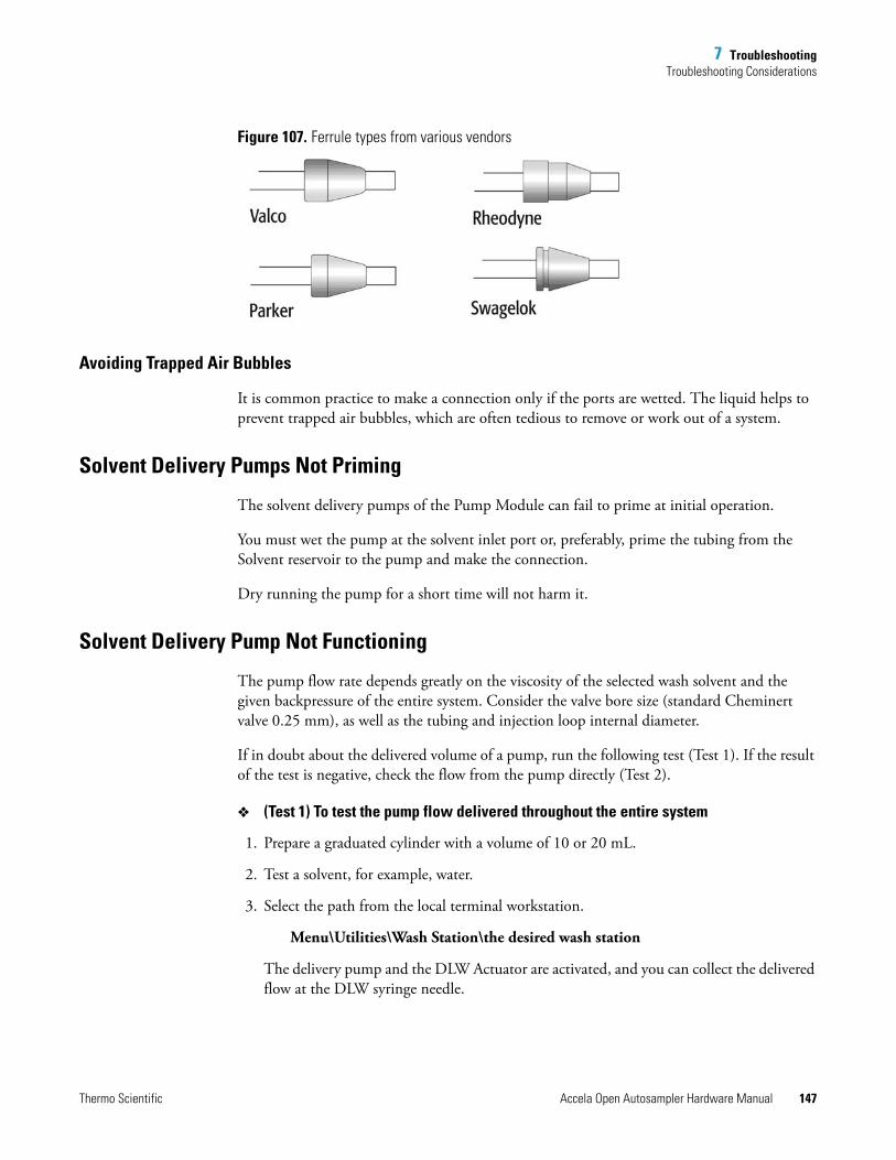
7 TroubleshootingTroubleshooting Considerations
Thermo Scientific Accela Open Autosampler Hardware Manual 147
Figure 107. Ferrule types from various vendors
Avoiding Trapped Air Bubbles
It is common practice to make a connection only if the ports are wetted. The liquid helps to prevent trapped air bubbles, which are often tedious to remove or work out of a system.
Solvent Delivery Pumps Not Priming
The solvent delivery pumps of the Pump Module can fail to prime at initial operation.
You must wet the pump at the solvent inlet port or, preferably, prime the tubing from the Solvent reservoir to the pump and make the connection.
Dry running the pump for a short time will not harm it.
Solvent Delivery Pump Not Functioning
The pump flow rate depends greatly on the viscosity of the selected wash solvent and the given backpressure of the entire system. Consider the valve bore size (standard Cheminert valve 0.25 mm), as well as the tubing and injection loop internal diameter.
If in doubt about the delivered volume of a pump, run the following test (Test 1). If the result of the test is negative, check the flow from the pump directly (Test 2).
(Test 1) To test the pump flow delivered throughout the entire system
1. Prepare a graduated cylinder with a volume of 10 or 20 mL.
2. Test a solvent, for example, water.
3. Select the path from the local terminal workstation.
Menu\Utilities\Wash Station\the desired wash station
The delivery pump and the DLW Actuator are activated, and you can collect the delivered flow at the DLW syringe needle.
7 TroubleshootingStandard Chromatographic Tests
148 Accela Open Autosampler Hardware Manual Thermo Scientific
Expected result: Collection of approximately 8 mL
(Water, DLW syringe needle, gauge 22)
(Test 2) To test the pump flow delivered at the pump outlet
1. Disconnect the outlet tube from the pump module.
2. Connect PEEK tubing with the following dimension to the outlet of the pump module: 85 mm (3.35 in.) ID, 0.25 mm (0.010 in.) ID.
3. If necessary, replace the solvent in the reservoir bottle with water.
4. Activate the pump by selecting this path:
Menu\F3-Setup\Objects\Events\Pwr-Out1 or Pwr-Out2
5. Collect the pumped water in a graduated cylinder.
Expected Result: Within 30 seconds, pump delivery of approximately 10 mL
This short test can indicate whether the system is performing as expected. If you observe no or very little flow, systematically check using a process of elimination. For more details, see Table 31.
Standard Chromatographic TestsThis section describes standard chromatographic tests for carryover and repeatability. These tests provide basic information for both users and technical support.
The tests described are examples only; vary them accordingly if the configuration of the HPLC system changes.
The first test uses PAL standard valves with a bore size of 0.25 mm to provide a flow rate range of 10 to 500 μL/min.
Both tests, carryover and repeatability, test conditions for UV and LC/MS detection.
Details are listed in the next section. Note that the given levels to reach for carryover and repeatability do not reflect the specification value. These described tests should give you confirmation if the system is working to expectation using reasonable effort and time. The tests are more comparable with an OQ Test (Operational Qualification Test).
Note The levels provided in these tests do not reflect the specification value for careover or repeatability. The test results will confirm if the system is working properly with reasonable effort and within the expected time frame. The tests are comparable to Operational Qualification (OQ) tests.
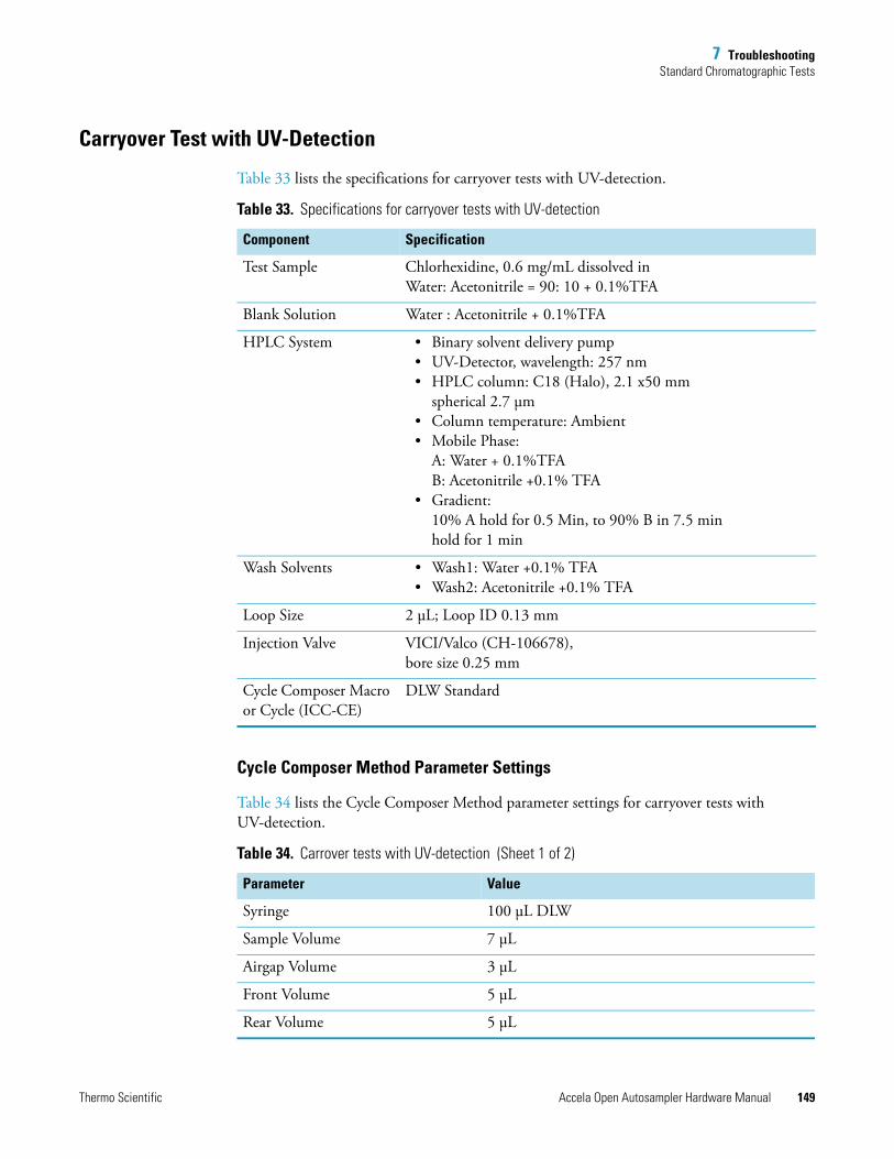
7 TroubleshootingStandard Chromatographic Tests
Thermo Scientific Accela Open Autosampler Hardware Manual 149
Carryover Test with UV-Detection
Table 33 lists the specifications for carryover tests with UV-detection.
Cycle Composer Method Parameter Settings
Table 34 lists the Cycle Composer Method parameter settings for carryover tests with UV-detection.
Table 33. Specifications for carryover tests with UV-detection
Component Specification
Test Sample Chlorhexidine, 0.6 mg/mL dissolved in Water: Acetonitrile = 90: 10 + 0.1%TFA
Blank Solution Water : Acetonitrile + 0.1%TFA
HPLC System • Binary solvent delivery pump• UV-Detector, wavelength: 257 nm• HPLC column: C18 (Halo), 2.1 x50 mm
spherical 2.7 μm• Column temperature: Ambient• Mobile Phase:
A: Water + 0.1%TFA B: Acetonitrile +0.1% TFA
• Gradient: 10% A hold for 0.5 Min, to 90% B in 7.5 minhold for 1 min
Wash Solvents • Wash1: Water +0.1% TFA• Wash2: Acetonitrile +0.1% TFA
Loop Size 2 μL; Loop ID 0.13 mm
Injection Valve VICI/Valco (CH-106678), bore size 0.25 mm
Cycle Composer Macro or Cycle (ICC-CE)
DLW Standard
Table 34. Carrover tests with UV-detection (Sheet 1 of 2)
Parameter Value
Syringe 100 μL DLW
Sample Volume 7 μL
Airgap Volume 3 μL
Front Volume 5 μL
Rear Volume 5 μL
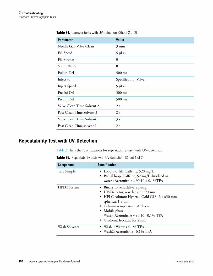
7 TroubleshootingStandard Chromatographic Tests
150 Accela Open Autosampler Hardware Manual Thermo Scientific
Repeatability Test with UV-Detection
Table 35 lists the specifications for repeatability tests with UV-detection.
Needle Gap Valve Clean 3 mm
Fill Speed 5 μL/s
Fill Strokes 0
Stator Wash 0
Pullup Del 500 ms
Inject to Specified Inj. Valve
Inject Speed 5 μL/s
Pre Inj Del 500 ms
Pst Inj Del 500 ms
Valve Clean Time Solvent 2 2 s
Post Clean Time Solvent 2 2 s
Valve Clean Time Solvent 1 3 s
Post Clean Time solvent 1 2 s
Table 34. Carrover tests with UV-detection (Sheet 2 of 2)
Parameter Value
Table 35. Repeatability tests with UV-detection (Sheet 1 of 2)
Component Specification
Test Sample • Loop overfill: Caffeine, 520 mg/L• Partial loop: Caffeine, 52 mg/L dissolved in
water : Acetonitrile = 90:10 + 0.1%TFA
HPLC System • Binary solvent delivery pump• UV-Detector, wavelength: 273 nm• HPLC column: Hypersil Gold C18, 2.1 ×50 mm
spherical 1.9 μm• Column temperature: Ambient• Mobile phase
Water: Acetonitrile = 90:10 +0.1% TFA• Gradient: Isocratic for 2 min
Wash Solvents • Wash1: Water + 0.1% TFA• Wash2: Acetonitrile +0.1% TFA
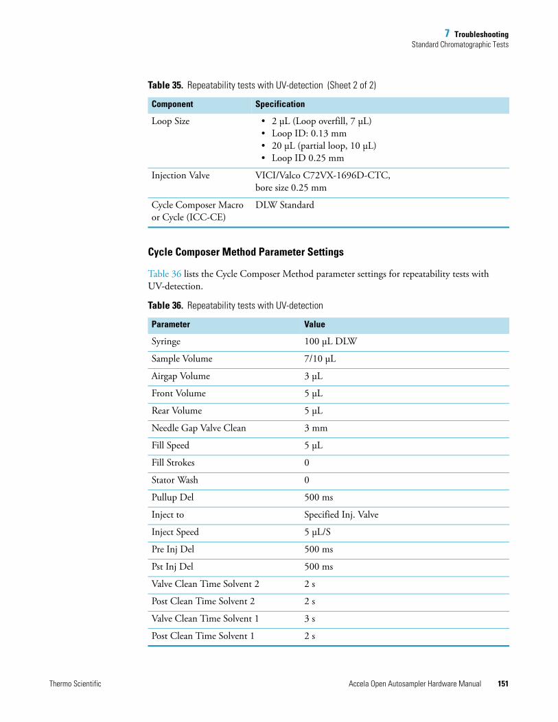
7 TroubleshootingStandard Chromatographic Tests
Thermo Scientific Accela Open Autosampler Hardware Manual 151
Cycle Composer Method Parameter Settings
Table 36 lists the Cycle Composer Method parameter settings for repeatability tests with UV-detection.
Loop Size • 2 μL (Loop overfill, 7 μL)• Loop ID: 0.13 mm• 20 μL (partial loop, 10 μL)• Loop ID 0.25 mm
Injection Valve VICI/Valco C72VX-1696D-CTC, bore size 0.25 mm
Cycle Composer Macro or Cycle (ICC-CE)
DLW Standard
Table 36. Repeatability tests with UV-detection
Parameter Value
Syringe 100 μL DLW
Sample Volume 7/10 μL
Airgap Volume 3 μL
Front Volume 5 μL
Rear Volume 5 μL
Needle Gap Valve Clean 3 mm
Fill Speed 5 μL
Fill Strokes 0
Stator Wash 0
Pullup Del 500 ms
Inject to Specified Inj. Valve
Inject Speed 5 μL/S
Pre Inj Del 500 ms
Pst Inj Del 500 ms
Valve Clean Time Solvent 2 2 s
Post Clean Time Solvent 2 2 s
Valve Clean Time Solvent 1 3 s
Post Clean Time Solvent 1 2 s
Table 35. Repeatability tests with UV-detection (Sheet 2 of 2)
Component Specification

Thermo Scientific Accela Open Autosampler Hardware Manual 153
8
Replacement Parts
This chapter describes the replacement parts for the Accela Open Autosampler and the Dynamic Load and Wash (DLW) option.
This section provides short descriptions of parts that can be replaced in the field.
Contents
• DLW Pump Module
• DLW Wash Station
• DLW Syringe
• DLW Syringe Holder Assembly
• DLW Option Spare Parts Ordering Information
• Control-xt Board
• Injection Valve and Valve Rotor
• Injection Unit
CAUTION
• Before attempting any type of maintenance, always disconnect the power cords from the power supply or from the various power supplies if optional devices are installed.
• To prevent possible shock, do not touch the capacitors. Capacitors inside the instrument can remain charged, even if the instrument is turned off.
• To avoid damaging electrical parts, do not disconnect an electrical assembly while power is supplied to the PAL System. Once the power is turned off, wait approximately 30 seconds before you disconnect an assembly.
8 Replacement PartsDLW Pump Module
154 Accela Open Autosampler Hardware Manual Thermo Scientific
DLW Pump ModuleYou can exchange the following parts individually from the DLW pump module:
• Single-pump module (incl. electrical connection)
• Solvent tubing kit
• Electrical cable (from pump module to PAL System)
• Pump control PCB
• DLW tubing kit
DLW Wash StationYou can exchange the following parts individually from the DLW wash station module.
• Wash station block
• Wash station inserts
• Waste tube
• Waste tube (valve-to-wash station)
• Dummy plugs
DLW SyringeYou can exchange the following parts individually from the DLW syringe assembly:
• DLW syringe 100 μL
• DLW syringe plunger (for syringe 100 μL)
• DLW syringe plunger holder
• DLW syringe retaining nut
• DLW syringe replaceable needles
DLW Syringe Holder AssemblyYou can exchange the following parts individually from the DLW syringe holder assembly:
• DLW syringe holder assembly (complete assembly)
Note The inserts and individual parts of the wash station block will be available in an update for this system part.
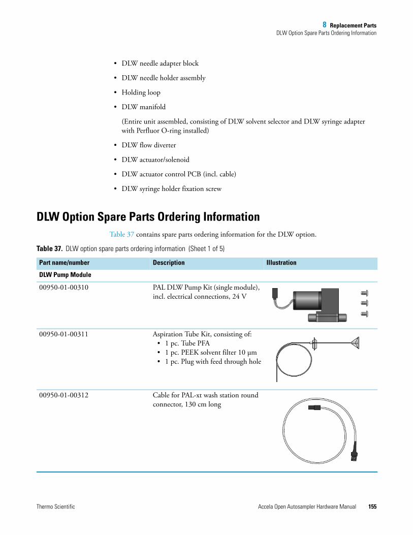
8 Replacement PartsDLW Option Spare Parts Ordering Information
Thermo Scientific Accela Open Autosampler Hardware Manual 155
• DLW needle adapter block
• DLW needle holder assembly
• Holding loop
• DLW manifold
(Entire unit assembled, consisting of DLW solvent selector and DLW syringe adapter with Perfluor O-ring installed)
• DLW flow diverter
• DLW actuator/solenoid
• DLW actuator control PCB (incl. cable)
• DLW syringe holder fixation screw
DLW Option Spare Parts Ordering InformationTable 37 contains spare parts ordering information for the DLW option.
Table 37. DLW option spare parts ordering information (Sheet 1 of 5)
Part name/number Description Illustration
DLW Pump Module
00950-01-00310 PAL DLW Pump Kit (single module), incl. electrical connections, 24 V
00950-01-00311 Aspiration Tube Kit, consisting of:• 1 pc. Tube PFA• 1 pc. PEEK solvent filter 10 μm• 1 pc. Plug with feed through hole
00950-01-00312 Cable for PAL-xt wash station round connector, 130 cm long
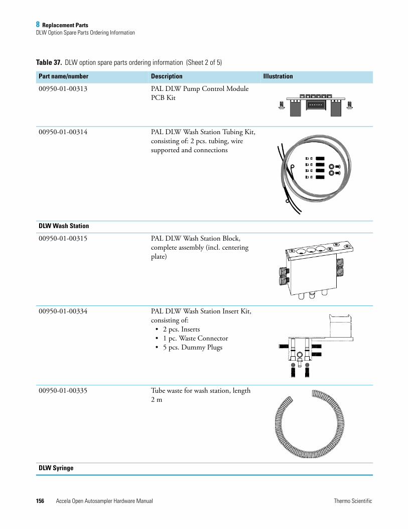
8 Replacement PartsDLW Option Spare Parts Ordering Information
156 Accela Open Autosampler Hardware Manual Thermo Scientific
00950-01-00313 PAL DLW Pump Control Module PCB Kit
00950-01-00314 PAL DLW Wash Station Tubing Kit, consisting of: 2 pcs. tubing, wire supported and connections
DLW Wash Station
00950-01-00315 PAL DLW Wash Station Block, complete assembly (incl. centering plate)
00950-01-00334 PAL DLW Wash Station Insert Kit, consisting of:
• 2 pcs. Inserts• 1 pc. Waste Connector• 5 pcs. Dummy Plugs
00950-01-00335 Tube waste for wash station, length 2 m
DLW Syringe
Table 37. DLW option spare parts ordering information (Sheet 2 of 5)
Part name/number Description Illustration
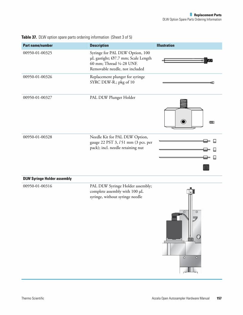
8 Replacement PartsDLW Option Spare Parts Ordering Information
Thermo Scientific Accela Open Autosampler Hardware Manual 157
00950-01-00325 Syringe for PAL DLW Option, 100 μL gastight; Ø7.7 mm; Scale Length 60 mm; Thread ¼-28 UNF. Removable needle, not included
00950-01-00326 Replacement plunger for syringe SYRC DLW-R.; pkg of 10
00950-01-00327 PAL DLW Plunger Holder
00950-01-00328 Needle Kit for PAL DLW Option, gauge 22 PST 3, l 51 mm (3 pcs. per pack); incl. needle retaining nut
DLW Syringe Holder assembly
00950-01-00316 PAL DLW Syringe Holder assembly; complete assembly with 100 μL syringe, without syringe needle
Table 37. DLW option spare parts ordering information (Sheet 3 of 5)
Part name/number Description Illustration
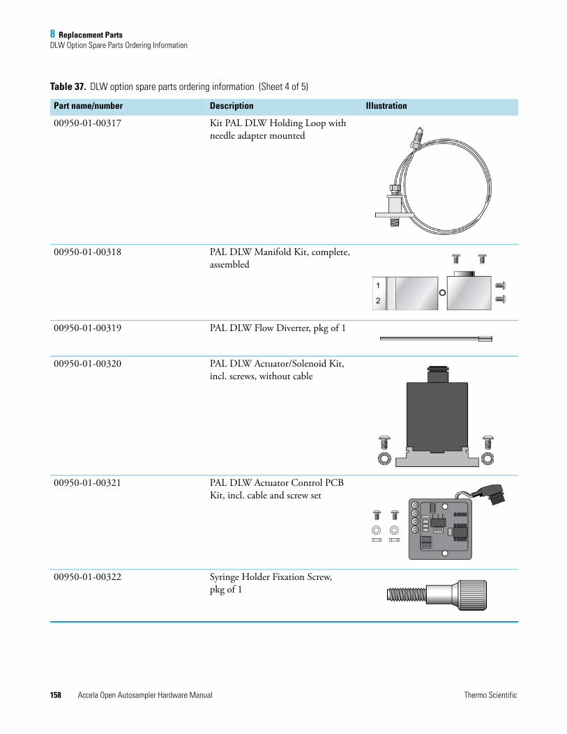
8 Replacement PartsDLW Option Spare Parts Ordering Information
158 Accela Open Autosampler Hardware Manual Thermo Scientific
00950-01-00317 Kit PAL DLW Holding Loop with needle adapter mounted
00950-01-00318 PAL DLW Manifold Kit, complete, assembled
00950-01-00319 PAL DLW Flow Diverter, pkg of 1
00950-01-00320 PAL DLW Actuator/Solenoid Kit, incl. screws, without cable
00950-01-00321 PAL DLW Actuator Control PCB Kit, incl. cable and screw set
00950-01-00322 Syringe Holder Fixation Screw, pkg of 1
Table 37. DLW option spare parts ordering information (Sheet 4 of 5)
Part name/number Description Illustration
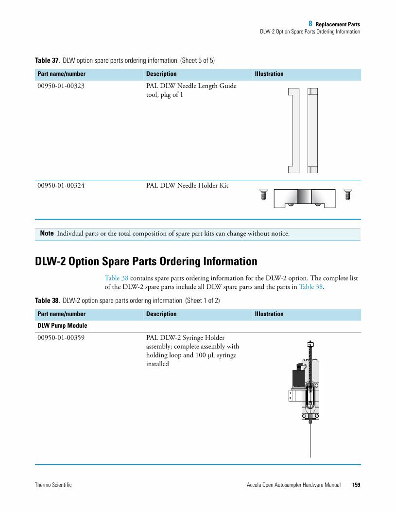
8 Replacement PartsDLW-2 Option Spare Parts Ordering Information
Thermo Scientific Accela Open Autosampler Hardware Manual 159
DLW-2 Option Spare Parts Ordering InformationTable 38 contains spare parts ordering information for the DLW-2 option. The complete list of the DLW-2 spare parts include all DLW spare parts and the parts in Table 38.
00950-01-00323 PAL DLW Needle Length Guide tool, pkg of 1
00950-01-00324 PAL DLW Needle Holder Kit
Table 37. DLW option spare parts ordering information (Sheet 5 of 5)
Part name/number Description Illustration
Note Indivdual parts or the total composition of spare part kits can change without notice.
Table 38. DLW-2 option spare parts ordering information (Sheet 1 of 2)
Part name/number Description Illustration
DLW Pump Module
00950-01-00359 PAL DLW-2 Syringe Holder assembly; complete assembly with holding loop and 100 μL syringe installed
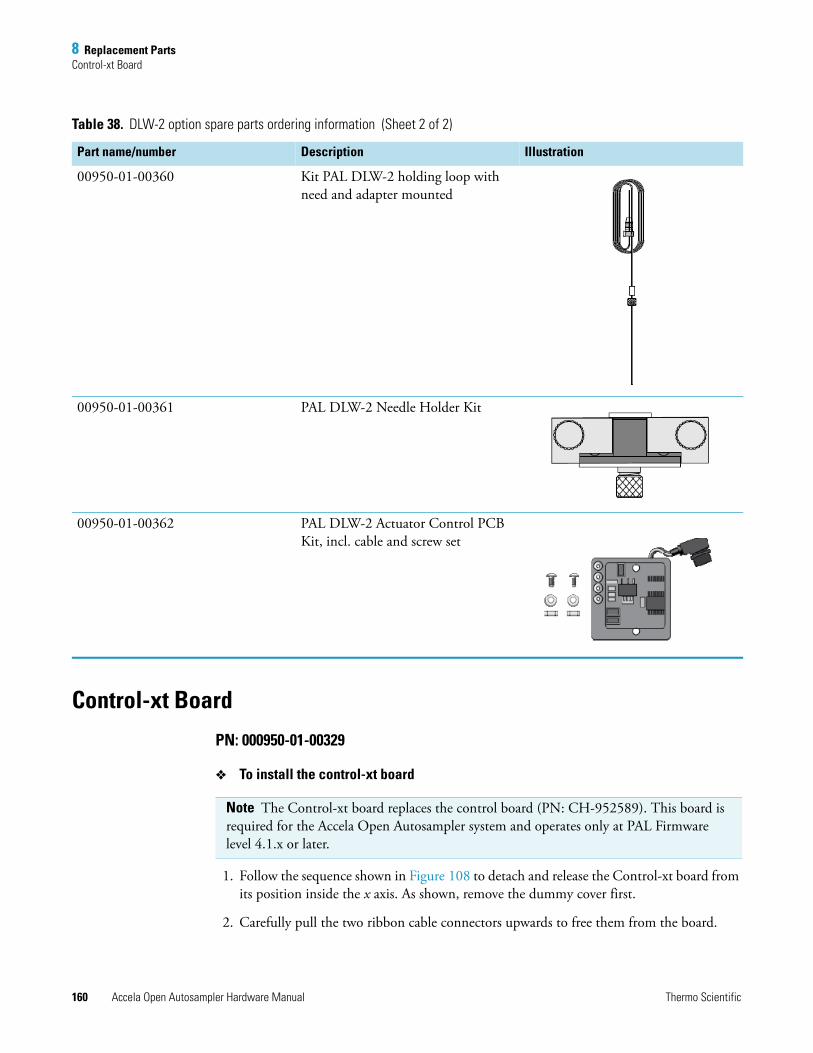
8 Replacement PartsControl-xt Board
160 Accela Open Autosampler Hardware Manual Thermo Scientific
Control-xt Board
PN: 000950-01-00329
To install the control-xt board
1. Follow the sequence shown in Figure 108 to detach and release the Control-xt board from its position inside the x axis. As shown, remove the dummy cover first.
2. Carefully pull the two ribbon cable connectors upwards to free them from the board.
00950-01-00360 Kit PAL DLW-2 holding loop with need and adapter mounted
00950-01-00361 PAL DLW-2 Needle Holder Kit
00950-01-00362 PAL DLW-2 Actuator Control PCB Kit, incl. cable and screw set
Table 38. DLW-2 option spare parts ordering information (Sheet 2 of 2)
Part name/number Description Illustration
Note The Control-xt board replaces the control board (PN: CH-952589). This board is required for the Accela Open Autosampler system and operates only at PAL Firmware level 4.1.x or later.
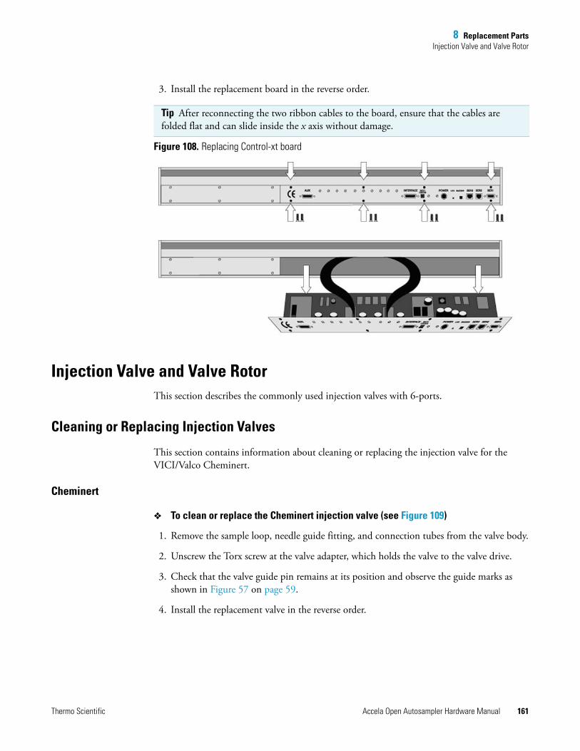
8 Replacement PartsInjection Valve and Valve Rotor
Thermo Scientific Accela Open Autosampler Hardware Manual 161
3. Install the replacement board in the reverse order.
Figure 108. Replacing Control-xt board
Injection Valve and Valve RotorThis section describes the commonly used injection valves with 6-ports.
Cleaning or Replacing Injection Valves
This section contains information about cleaning or replacing the injection valve for the VICI/Valco Cheminert.
Cheminert
To clean or replace the Cheminert injection valve (see Figure 109)
1. Remove the sample loop, needle guide fitting, and connection tubes from the valve body.
2. Unscrew the Torx screw at the valve adapter, which holds the valve to the valve drive.
3. Check that the valve guide pin remains at its position and observe the guide marks as shown in Figure 57 on page 59.
4. Install the replacement valve in the reverse order.
Tip After reconnecting the two ribbon cables to the board, ensure that the cables are folded flat and can slide inside the x axis without damage.
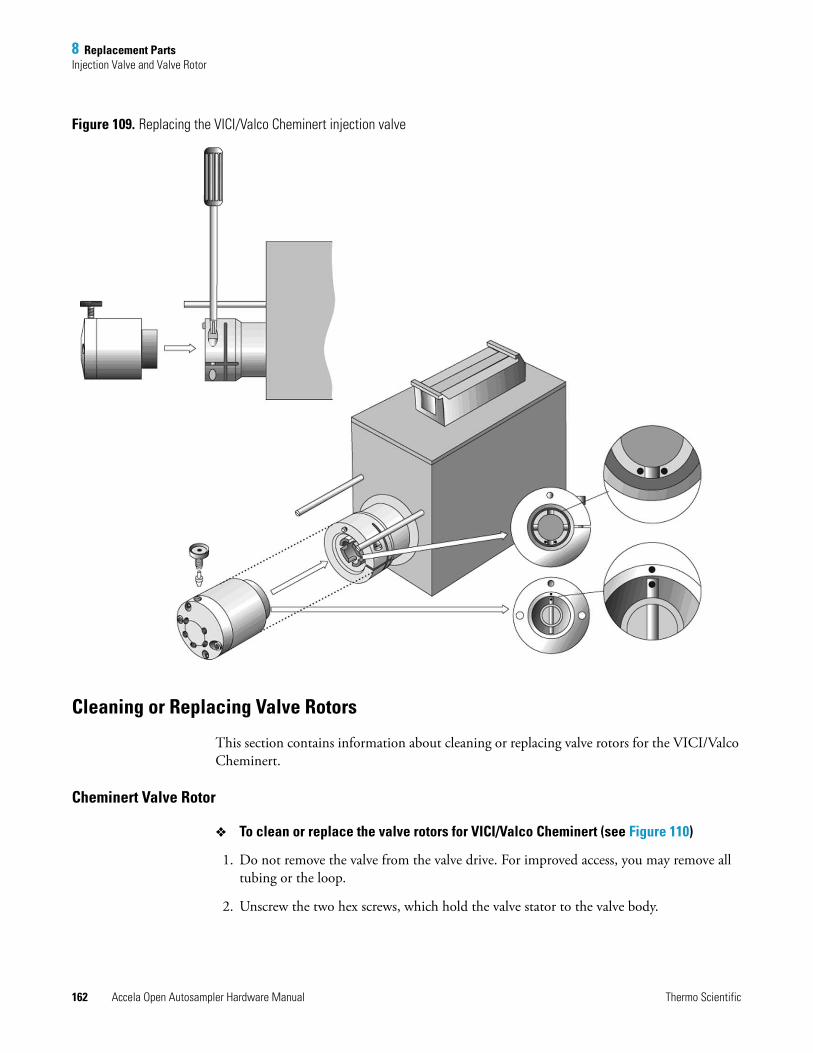
8 Replacement PartsInjection Valve and Valve Rotor
162 Accela Open Autosampler Hardware Manual Thermo Scientific
Figure 109. Replacing the VICI/Valco Cheminert injection valve
Cleaning or Replacing Valve Rotors
This section contains information about cleaning or replacing valve rotors for the VICI/Valco Cheminert.
Cheminert Valve Rotor
To clean or replace the valve rotors for VICI/Valco Cheminert (see Figure 110)
1. Do not remove the valve from the valve drive. For improved access, you may remove all tubing or the loop.
2. Unscrew the two hex screws, which hold the valve stator to the valve body.
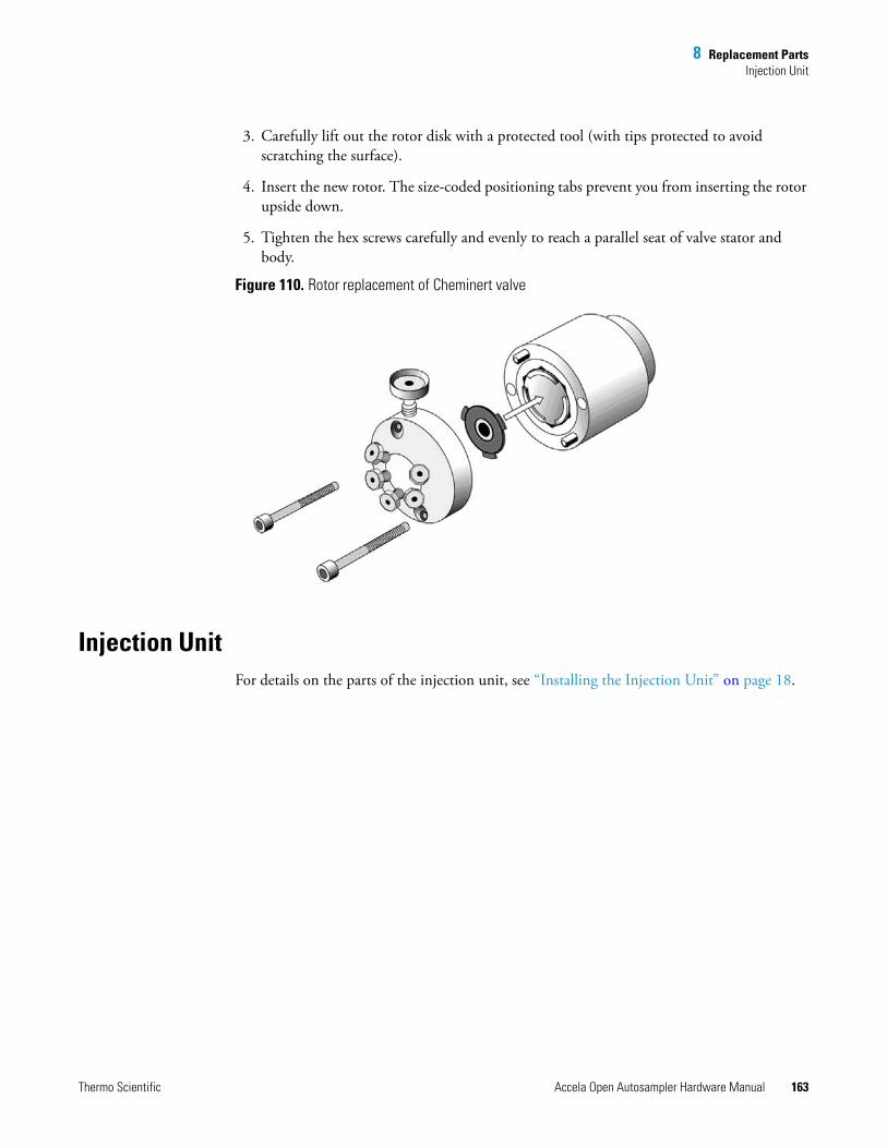
8 Replacement PartsInjection Unit
Thermo Scientific Accela Open Autosampler Hardware Manual 163
3. Carefully lift out the rotor disk with a protected tool (with tips protected to avoid scratching the surface).
4. Insert the new rotor. The size-coded positioning tabs prevent you from inserting the rotor upside down.
5. Tighten the hex screws carefully and evenly to reach a parallel seat of valve stator and body.
Figure 110. Rotor replacement of Cheminert valve
Injection UnitFor details on the parts of the injection unit, see “Installing the Injection Unit” on page 18.

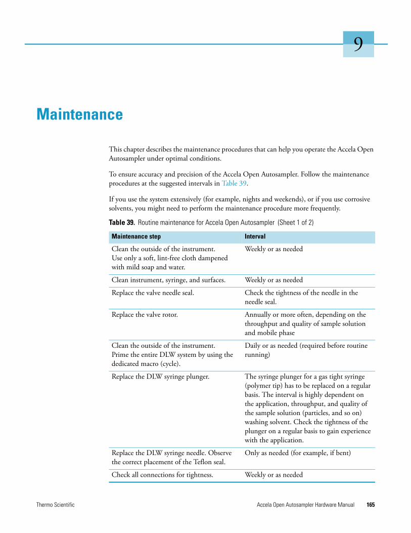
Thermo Scientific Accela Open Autosampler Hardware Manual 165
9
Maintenance
This chapter describes the maintenance procedures that can help you operate the Accela Open Autosampler under optimal conditions.
To ensure accuracy and precision of the Accela Open Autosampler. Follow the maintenance procedures at the suggested intervals in Table 39.
If you use the system extensively (for example, nights and weekends), or if you use corrosive solvents, you might need to perform the maintenance procedure more frequently.
Table 39. Routine maintenance for Accela Open Autosampler (Sheet 1 of 2)
Maintenance step Interval
Clean the outside of the instrument. Use only a soft, lint-free cloth dampened with mild soap and water.
Weekly or as needed
Clean instrument, syringe, and surfaces. Weekly or as needed
Replace the valve needle seal. Check the tightness of the needle in the needle seal.
Replace the valve rotor. Annually or more often, depending on the throughput and quality of sample solution and mobile phase
Clean the outside of the instrument. Prime the entire DLW system by using the dedicated macro (cycle).
Daily or as needed (required before routine running)
Replace the DLW syringe plunger. The syringe plunger for a gas tight syringe (polymer tip) has to be replaced on a regular basis. The interval is highly dependent on the application, throughput, and quality of the sample solution (particles, and so on) washing solvent. Check the tightness of the plunger on a regular basis to gain experience with the application.
Replace the DLW syringe needle. Observe the correct placement of the Teflon seal.
Only as needed (for example, if bent)
Check all connections for tightness. Weekly or as needed
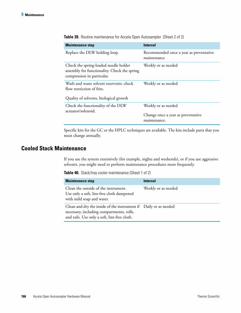
9 Maintenance
166 Accela Open Autosampler Hardware Manual Thermo Scientific
Specific kits for the GC or the HPLC techniques are available. The kits include parts that you must change annually.
Cooled Stack Maintenance
If you use the system extensively (for example, nights and weekends), or if you use aggressive solvents, you might need to perform maintenance procedures more frequently.
Replace the DLW holding loop. Recommended once a year as preventative maintenance
Check the spring-loaded needle holder assembly for functionality. Check the spring compression in particular.
Weekly or as needed
Wash and waste solvent reservoirs: check flow restriction of frits.
Quality of solvents, biological growth
Weekly or as needed
Check the functionality of the DLW actuator/solenoid.
Weekly or as needed
Change once a year as preventative maintenance.
Table 39. Routine maintenance for Accela Open Autosampler (Sheet 2 of 2)
Maintenance step Interval
Table 40. Stack/tray cooler maintenance (Sheet 1 of 2)
Maintenance step Interval
Clean the outside of the instrument.Use only a soft, lint-free cloth dampened with mild soap and water.
Weekly or as needed
Clean and dry the inside of the instrument if necessary, including compartments, rolls, and rails. Use only a soft, lint-free cloth.
Daily or as needed
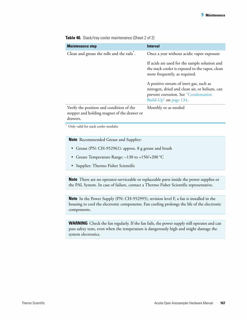
9 Maintenance
Thermo Scientific Accela Open Autosampler Hardware Manual 167
Clean and grease the rolls and the rails*. Once a year without acidic vapor exposure
If acids are used for the sample solution and the stack cooler is exposed to the vapor, clean more frequently, as required.
A positive stream of inert gas, such as nitrogen, dried and clean air, or helium, can prevent corrosion. See “Condensation Build-Up” on page 134.
Verify the position and condition of the stopper and holding magnet of the drawer or drawers.
Monthly or as needed
* Only valid for stack cooler modules
Note Recommended Grease and Supplier:
• Grease (PN: CH-952961): approx. 8 g grease and brush
• Grease Temperature Range: –130 to +150/+200 °C
• Supplier: Thermo Fisher Scientific
Note There are no operator-serviceable or replaceable parts inside the power supplies or the PAL System. In case of failure, contact a Thermo Fisher Scientific representative.
Note In the Power Supply (PN: CH-952995), revision level F, a fan is installed in the housing to cool the electronic components. Fan cooling prolongs the life of the electronic components.
WARNING Check the fan regularly. If the fan fails, the power supply still operates and can pass safety tests, even when the temperature is dangerously high and might damage the system electronics.
Table 40. Stack/tray cooler maintenance (Sheet 2 of 2)
Maintenance step Interval

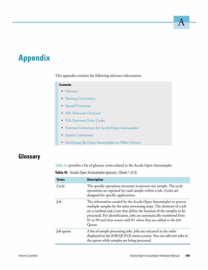
Thermo Scientific Accela Open Autosampler Hardware Manual 169
A
Appendix
This appendix contains the following reference information.
GlossaryTable 41 provides a list of glossary terms related to the Accela Open Autosampler.
Contents
• Glossary
• Naming Convention
• Special Functions
• PAL Firmware Overview
• PAL Firmware Error Codes
• External Connectors for Accela Open Autosampler
• System Limitations
• Interfacing the Open Autosampler to Other Devices
Table 41. Accela Open Autosampler glossary (Sheet 1 of 3)
Terms Description
Cycle The specific operations necessary to process one sample. The cycle operations are repeated for each sample within a job. Cycles are designed for specific applications.
Job The information needed by the Accela Open Autosampler to process multiple samples by the same processing steps. The elements of a job are a method and a tray that define the location of the samples to be processed. For identification, jobs are automatically numbered from 01 to 99 and then restart with 01 when they are added to the Job Queue.
Job queue A list of sample processing jobs. Jobs are executed in the order displayed on the JOB QUEUE menu screens. You can add new jobs to the queue while samples are being processed.
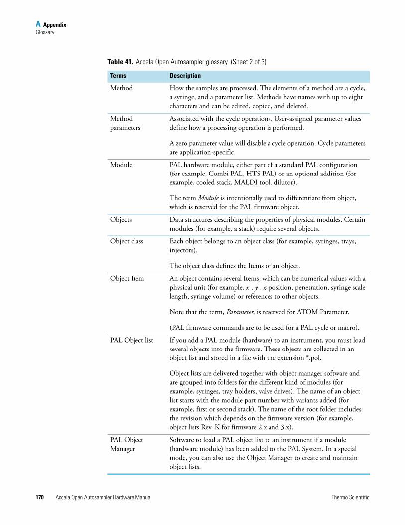
A AppendixGlossary
170 Accela Open Autosampler Hardware Manual Thermo Scientific
Method How the samples are processed. The elements of a method are a cycle, a syringe, and a parameter list. Methods have names with up to eight characters and can be edited, copied, and deleted.
Method parameters
Associated with the cycle operations. User-assigned parameter values define how a processing operation is performed.
A zero parameter value will disable a cycle operation. Cycle parameters are application-specific.
Module PAL hardware module, either part of a standard PAL configuration (for example, Combi PAL, HTS PAL) or an optional addition (for example, cooled stack, MALDI tool, dilutor).
The term Module is intentionally used to differentiate from object, which is reserved for the PAL firmware object.
Objects Data structures describing the properties of physical modules. Certain modules (for example, a stack) require several objects.
Object class Each object belongs to an object class (for example, syringes, trays, injectors).
The object class defines the Items of an object.
Object Item An object contains several Items, which can be numerical values with a physical unit (for example, x-, y-, z-position, penetration, syringe scale length, syringe volume) or references to other objects.
Note that the term, Parameter, is reserved for ATOM Parameter.
(PAL firmware commands are to be used for a PAL cycle or macro).
PAL Object list If you add a PAL module (hardware) to an instrument, you must load several objects into the firmware. These objects are collected in an object list and stored in a file with the extension *.pol.
Object lists are delivered together with object manager software and are grouped into folders for the different kind of modules (for example, syringes, tray holders, valve drives). The name of an object list starts with the module part number with variants added (for example, first or second stack). The name of the root folder includes the revision which depends on the firmware version (for example, object lists Rev. K for firmware 2.x and 3.x).
PAL Object Manager
Software to load a PAL object list to an instrument if a module (hardware module) has been added to the PAL System. In a special mode, you can also use the Object Manager to create and maintain object lists.
Table 41. Accela Open Autosampler glossary (Sheet 2 of 3)
Terms Description
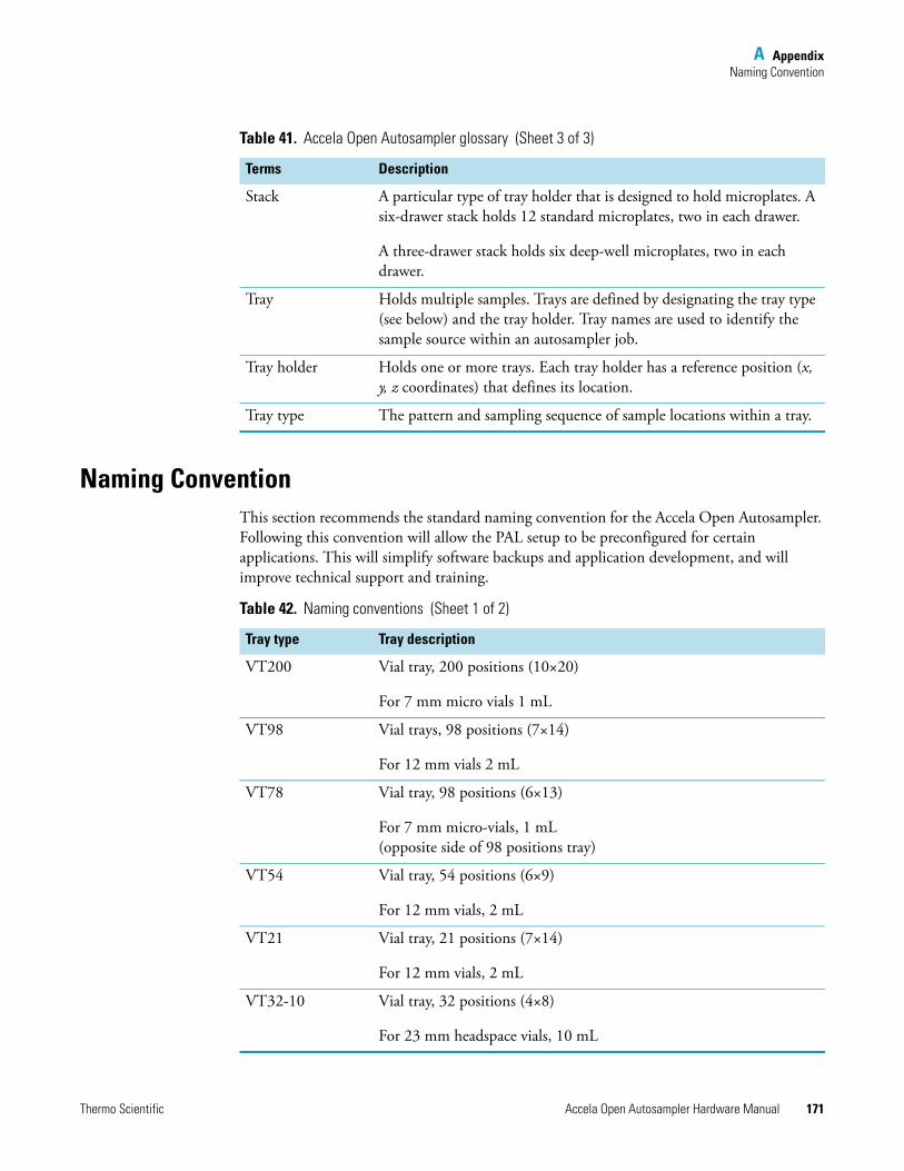
A AppendixNaming Convention
Thermo Scientific Accela Open Autosampler Hardware Manual 171
Naming ConventionThis section recommends the standard naming convention for the Accela Open Autosampler. Following this convention will allow the PAL setup to be preconfigured for certain applications. This will simplify software backups and application development, and will improve technical support and training.
Stack A particular type of tray holder that is designed to hold microplates. A six-drawer stack holds 12 standard microplates, two in each drawer.
A three-drawer stack holds six deep-well microplates, two in each drawer.
Tray Holds multiple samples. Trays are defined by designating the tray type (see below) and the tray holder. Tray names are used to identify the sample source within an autosampler job.
Tray holder Holds one or more trays. Each tray holder has a reference position (x, y, z coordinates) that defines its location.
Tray type The pattern and sampling sequence of sample locations within a tray.
Table 41. Accela Open Autosampler glossary (Sheet 3 of 3)
Terms Description
Table 42. Naming conventions (Sheet 1 of 2)
Tray type Tray description
VT200 Vial tray, 200 positions (10×20)
For 7 mm micro vials 1 mL
VT98 Vial trays, 98 positions (7×14)
For 12 mm vials 2 mL
VT78 Vial tray, 98 positions (6×13)
For 7 mm micro-vials, 1 mL(opposite side of 98 positions tray)
VT54 Vial tray, 54 positions (6×9)
For 12 mm vials, 2 mL
VT21 Vial tray, 21 positions (7×14)
For 12 mm vials, 2 mL
VT32-10 Vial tray, 32 positions (4×8)
For 23 mm headspace vials, 10 mL
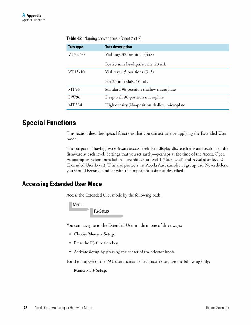
A AppendixSpecial Functions
172 Accela Open Autosampler Hardware Manual Thermo Scientific
Special FunctionsThis section describes special functions that you can activate by applying the Extended User mode.
The purpose of having two software access levels is to display discrete items and sections of the firmware at each level. Settings that you set rarely—perhaps at the time of the Accela Open Autosampler system installation—are hidden at level 1 (User Level) and revealed at level 2 (Extended User Level). This also protects the Accela Autosampler in group use. Nevertheless, you should become familiar with the important points as described.
Accessing Extended User Mode
Access the Extended User mode by the following path:
You can navigate to the Extended User mode in one of three ways:
• Choose Menu > Setup.
• Press the F3 function key.
• Activate Setup by pressing the center of the selector knob.
For the purpose of the PAL user manual or technical notes, use the following only:
Menu > F3-Setup.
VT32-20 Vial tray, 32 positions (4×8)
For 23 mm headspace vials, 20 mL
VT15-10 Vial tray, 15 positions (3×5)
For 23 mm vials, 10 mL
MT96 Standard 96-position shallow microplate
DW96 Deep well 96-position microplate
MT384 High density 384-position shallow microplate
Table 42. Naming conventions (Sheet 2 of 2)
Tray type Tray description
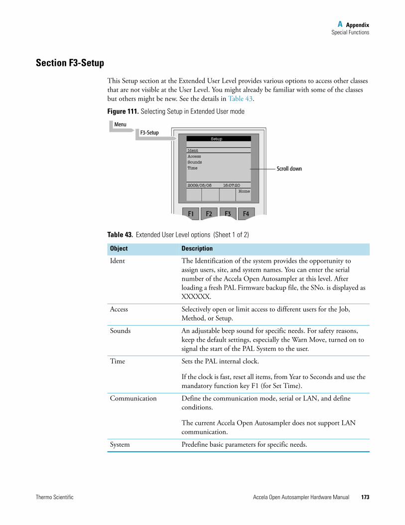
A AppendixSpecial Functions
Thermo Scientific Accela Open Autosampler Hardware Manual 173
Section F3-Setup
This Setup section at the Extended User Level provides various options to access other classes that are not visible at the User Level. You might already be familiar with some of the classes but others might be new. See the details in Table 43.
Figure 111. Selecting Setup in Extended User mode
Table 43. Extended User Level options (Sheet 1 of 2)
Object Description
Ident The Identification of the system provides the opportunity to assign users, site, and system names. You can enter the serial number of the Accela Open Autosampler at this level. After loading a fresh PAL Firmware backup file, the SNo. is displayed as XXXXXX.
Access Selectively open or limit access to different users for the Job, Method, or Setup.
Sounds An adjustable beep sound for specific needs. For safety reasons, keep the default settings, especially the Warn Move, turned on to signal the start of the PAL System to the user.
Time Sets the PAL internal clock.
If the clock is fast, reset all items, from Year to Seconds and use the mandatory function key F1 (for Set Time).
Communication Define the communication mode, serial or LAN, and define conditions.
The current Accela Open Autosampler does not support LAN communication.
System Predefine basic parameters for specific needs.
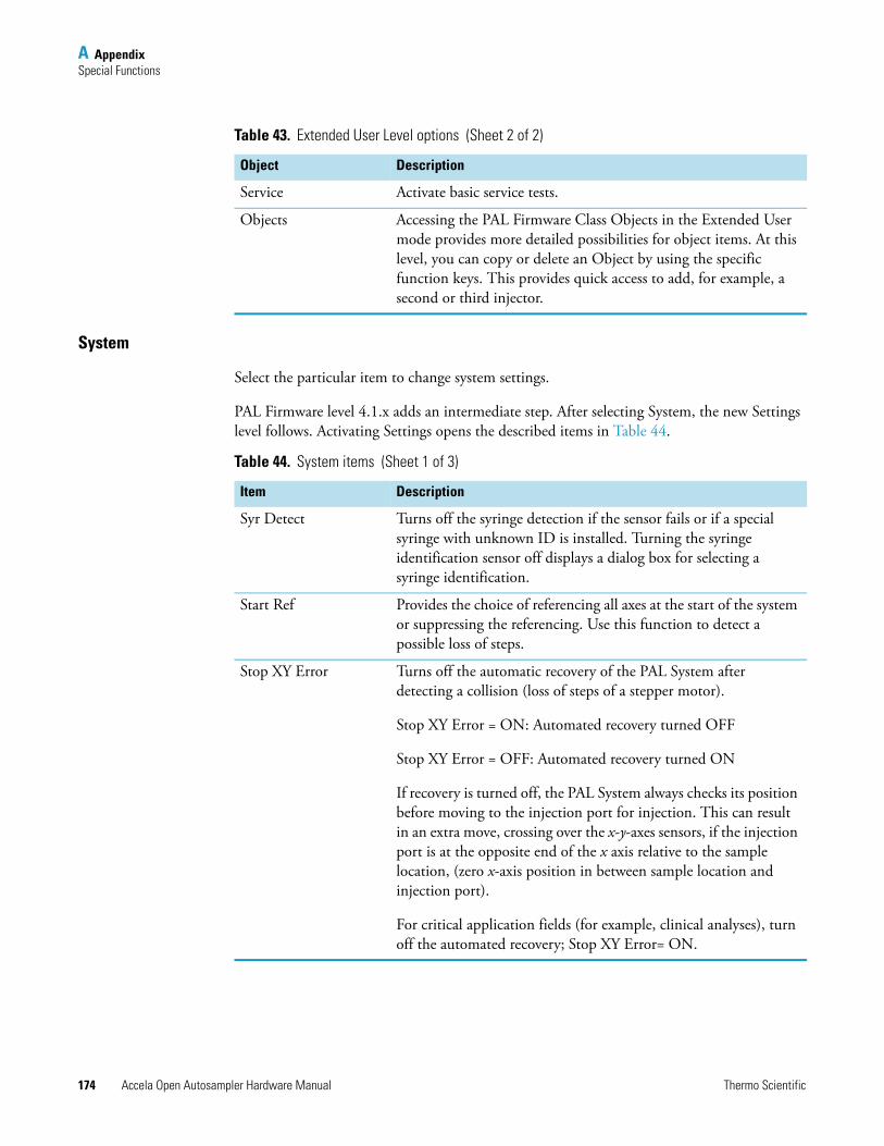
A AppendixSpecial Functions
174 Accela Open Autosampler Hardware Manual Thermo Scientific
System
Select the particular item to change system settings.
PAL Firmware level 4.1.x adds an intermediate step. After selecting System, the new Settings level follows. Activating Settings opens the described items in Table 44.
Service Activate basic service tests.
Objects Accessing the PAL Firmware Class Objects in the Extended User mode provides more detailed possibilities for object items. At this level, you can copy or delete an Object by using the specific function keys. This provides quick access to add, for example, a second or third injector.
Table 43. Extended User Level options (Sheet 2 of 2)
Object Description
Table 44. System items (Sheet 1 of 3)
Item Description
Syr Detect Turns off the syringe detection if the sensor fails or if a special syringe with unknown ID is installed. Turning the syringe identification sensor off displays a dialog box for selecting a syringe identification.
Start Ref Provides the choice of referencing all axes at the start of the system or suppressing the referencing. Use this function to detect a possible loss of steps.
Stop XY Error Turns off the automatic recovery of the PAL System after detecting a collision (loss of steps of a stepper motor).
Stop XY Error = ON: Automated recovery turned OFF
Stop XY Error = OFF: Automated recovery turned ON
If recovery is turned off, the PAL System always checks its position before moving to the injection port for injection. This can result in an extra move, crossing over the x-y-axes sensors, if the injection port is at the opposite end of the x axis relative to the sample location, (zero x-axis position in between sample location and injection port).
For critical application fields (for example, clinical analyses), turn off the automated recovery; Stop XY Error= ON.
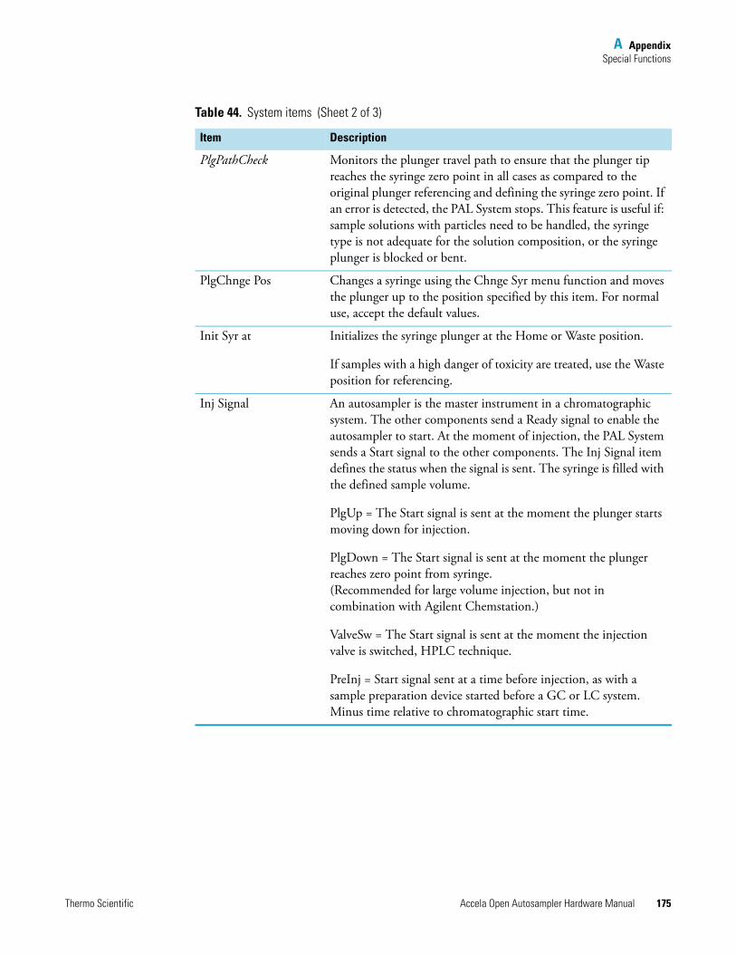
A AppendixSpecial Functions
Thermo Scientific Accela Open Autosampler Hardware Manual 175
PlgPathCheck Monitors the plunger travel path to ensure that the plunger tip reaches the syringe zero point in all cases as compared to the original plunger referencing and defining the syringe zero point. If an error is detected, the PAL System stops. This feature is useful if: sample solutions with particles need to be handled, the syringe type is not adequate for the solution composition, or the syringe plunger is blocked or bent.
PlgChnge Pos Changes a syringe using the Chnge Syr menu function and moves the plunger up to the position specified by this item. For normal use, accept the default values.
Init Syr at Initializes the syringe plunger at the Home or Waste position.
If samples with a high danger of toxicity are treated, use the Waste position for referencing.
Inj Signal An autosampler is the master instrument in a chromatographic system. The other components send a Ready signal to enable the autosampler to start. At the moment of injection, the PAL System sends a Start signal to the other components. The Inj Signal item defines the status when the signal is sent. The syringe is filled with the defined sample volume.
PlgUp = The Start signal is sent at the moment the plunger starts moving down for injection.
PlgDown = The Start signal is sent at the moment the plunger reaches zero point from syringe. (Recommended for large volume injection, but not in combination with Agilent Chemstation.)
ValveSw = The Start signal is sent at the moment the injection valve is switched, HPLC technique.
PreInj = Start signal sent at a time before injection, as with a sample preparation device started before a GC or LC system. Minus time relative to chromatographic start time.
Table 44. System items (Sheet 2 of 3)
Item Description
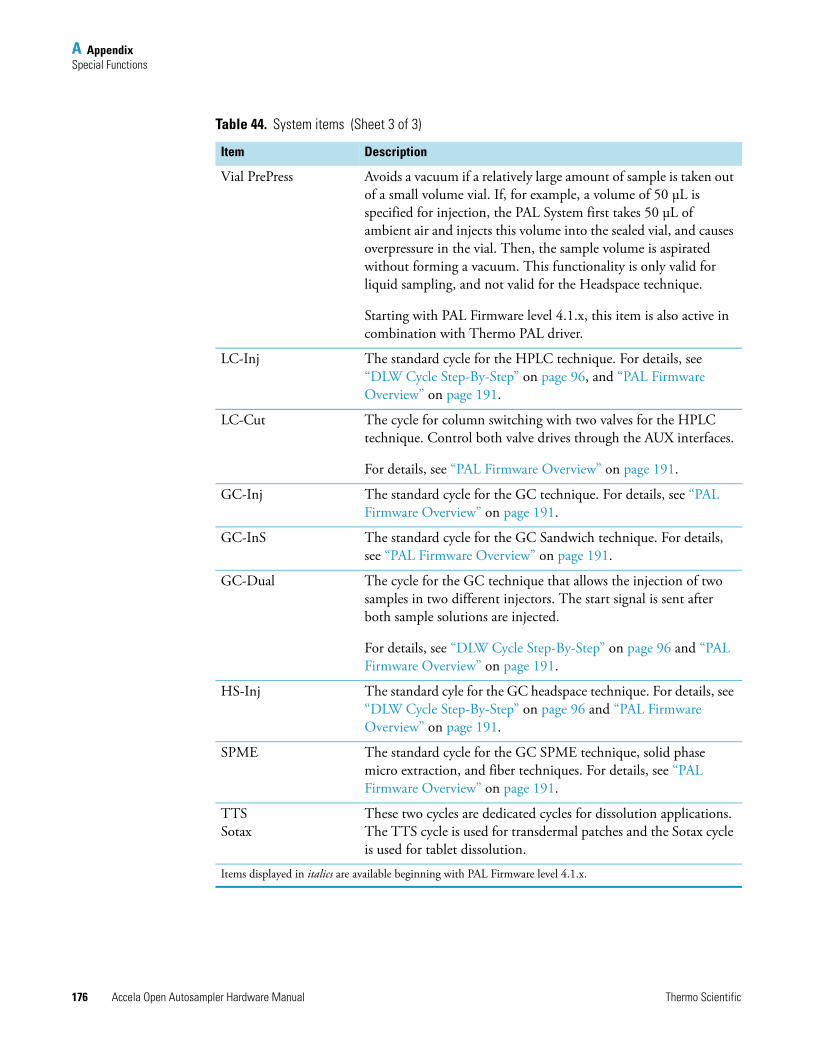
A AppendixSpecial Functions
176 Accela Open Autosampler Hardware Manual Thermo Scientific
Vial PrePress Avoids a vacuum if a relatively large amount of sample is taken out of a small volume vial. If, for example, a volume of 50 μL is specified for injection, the PAL System first takes 50 μL of ambient air and injects this volume into the sealed vial, and causes overpressure in the vial. Then, the sample volume is aspirated without forming a vacuum. This functionality is only valid for liquid sampling, and not valid for the Headspace technique.
Starting with PAL Firmware level 4.1.x, this item is also active in combination with Thermo PAL driver.
LC-Inj The standard cycle for the HPLC technique. For details, see “DLW Cycle Step-By-Step” on page 96, and “PAL Firmware Overview” on page 191.
LC-Cut The cycle for column switching with two valves for the HPLC technique. Control both valve drives through the AUX interfaces.
For details, see “PAL Firmware Overview” on page 191.
GC-Inj The standard cycle for the GC technique. For details, see “PAL Firmware Overview” on page 191.
GC-InS The standard cycle for the GC Sandwich technique. For details, see “PAL Firmware Overview” on page 191.
GC-Dual The cycle for the GC technique that allows the injection of two samples in two different injectors. The start signal is sent after both sample solutions are injected.
For details, see “DLW Cycle Step-By-Step” on page 96 and “PAL Firmware Overview” on page 191.
HS-Inj The standard cyle for the GC headspace technique. For details, see “DLW Cycle Step-By-Step” on page 96 and “PAL Firmware Overview” on page 191.
SPME The standard cycle for the GC SPME technique, solid phase micro extraction, and fiber techniques. For details, see “PAL Firmware Overview” on page 191.
TTSSotax
These two cycles are dedicated cycles for dissolution applications. The TTS cycle is used for transdermal patches and the Sotax cycle is used for tablet dissolution.
Items displayed in italics are available beginning with PAL Firmware level 4.1.x.
Table 44. System items (Sheet 3 of 3)
Item Description
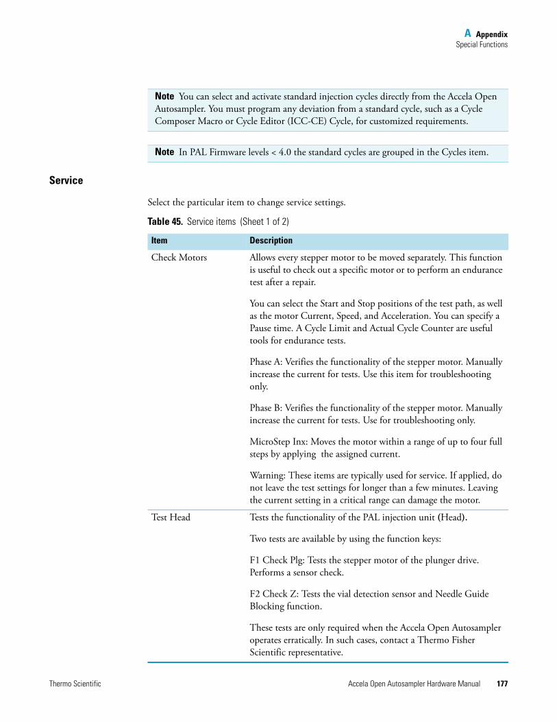
A AppendixSpecial Functions
Thermo Scientific Accela Open Autosampler Hardware Manual 177
Service
Select the particular item to change service settings.
Note You can select and activate standard injection cycles directly from the Accela Open Autosampler. You must program any deviation from a standard cycle, such as a Cycle Composer Macro or Cycle Editor (ICC-CE) Cycle, for customized requirements.
Note In PAL Firmware levels < 4.0 the standard cycles are grouped in the Cycles item.
Table 45. Service items (Sheet 1 of 2)
Item Description
Check Motors Allows every stepper motor to be moved separately. This function is useful to check out a specific motor or to perform an endurance test after a repair.
You can select the Start and Stop positions of the test path, as well as the motor Current, Speed, and Acceleration. You can specify a Pause time. A Cycle Limit and Actual Cycle Counter are useful tools for endurance tests.
Phase A: Verifies the functionality of the stepper motor. Manually increase the current for tests. Use this item for troubleshooting only.
Phase B: Verifies the functionality of the stepper motor. Manually increase the current for tests. Use for troubleshooting only.
MicroStep Inx: Moves the motor within a range of up to four full steps by applying the assigned current.
Warning: These items are typically used for service. If applied, do not leave the test settings for longer than a few minutes. Leaving the current setting in a critical range can damage the motor.
Test Head Tests the functionality of the PAL injection unit (Head).
Two tests are available by using the function keys:
F1 Check Plg: Tests the stepper motor of the plunger drive. Performs a sensor check.
F2 Check Z: Tests the vial detection sensor and Needle Guide Blocking function.
These tests are only required when the Accela Open Autosampler operates erratically. In such cases, contact a Thermo Fisher Scientific representative.
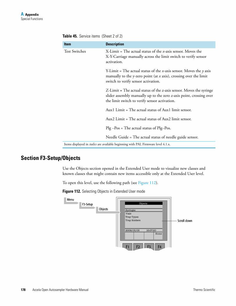
A AppendixSpecial Functions
178 Accela Open Autosampler Hardware Manual Thermo Scientific
Section F3-Setup/Objects
Use the Objects section opened in the Extended User mode to visualize new classes and known classes that might contain new items accessible only at the Extended User level.
To open this level, use the following path (see Figure 112).
Figure 112. Selecting Objects in Extended User mode
Test Switches X-Limit = The actual status of the x-axis sensor. Moves the X-Y-Carriage manually across the limit switch to verify sensor activation.
Y-Limit = The actual status of the x-axis sensor. Moves the y axis manually to the y-zero point (at x axis), crossing over the limit switch to verify sensor activation.
Z-Limit = The actual status of the z-axis sensor. Moves the syringe slider assembly manually up to the zero z-axis point, crossing over the limit switch to verify sensor activation.
Aux1 Limit = The actual status of Aux1 limit sensor.
Aux2 Limit = The actual status of Aux2 limit sensor.
Plg –Pos = The actual status of Plg–Pos.
Needle Guide = The actual status of needle guide sensor.
Items displayed in italics are available beginning with PAL Firmware level 4.1.x.
Table 45. Service items (Sheet 2 of 2)
Item Description
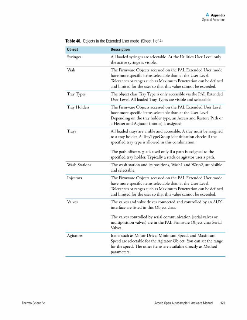
A AppendixSpecial Functions
Thermo Scientific Accela Open Autosampler Hardware Manual 179
Table 46. Objects in the Extended User mode (Sheet 1 of 4)
Object Description
Syringes All loaded syringes are selectable. At the Utilities User Level only the active syringe is visible.
Vials The Firmware Objects accessed on the PAL Extended User mode have more specific items selectable than at the User Level. Tolerances or ranges such as Maximum Penetration can be defined and limited for the user so that this value cannot be exceeded.
Tray Types The object class Tray Type is only accessible via the PAL Extended User Level. All loaded Tray Types are visible and selectable.
Tray Holders The Firmware Objects accessed on the PAL Extended User Level have more specific items selectable than at the User Level. Depending on the tray holder type, an Access and Restore Path or a Heater and Agitator (motor) is assigned.
Trays All loaded trays are visible and accessible. A tray must be assigned to a tray holder. A TrayTypeGroup identification checks if the specified tray type is allowed in this combination.
The path offset x, y, z is used only if a path is assigned to the specified tray holder. Typically a stack or agitator uses a path.
Wash Stations The wash station and its positions, Wash1 and Wash2, are visible and selectable.
Injectors The Firmware Objects accessed on the PAL Extended User mode have more specific items selectable than at the User Level. Tolerances or ranges such as Maximum Penetration can be defined and limited for the user so that this value cannot be exceeded.
Valves The valves and valve drives connected and controlled by an AUX interface are listed in this Object class.
The valves controlled by serial communication (serial valves or multiposition valves) are in the PAL Firmware Object class Serial Valves.
Agitators Items such as Motor Drive, Minimum Speed, and Maximum Speed are selectable for the Agitator Object. You can set the range for the speed. The other items are available directly as Method parameters.
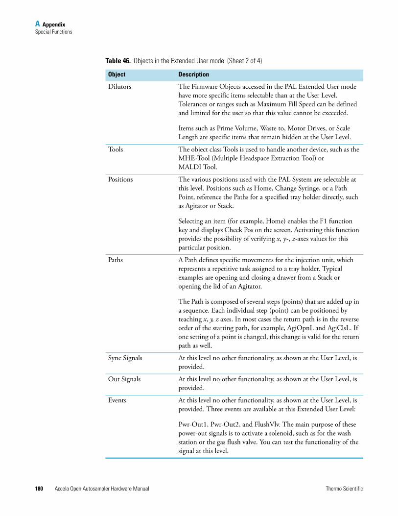
A AppendixSpecial Functions
180 Accela Open Autosampler Hardware Manual Thermo Scientific
Dilutors The Firmware Objects accessed in the PAL Extended User mode have more specific items selectable than at the User Level. Tolerances or ranges such as Maximum Fill Speed can be defined and limited for the user so that this value cannot be exceeded.
Items such as Prime Volume, Waste to, Motor Drives, or Scale Length are specific items that remain hidden at the User Level.
Tools The object class Tools is used to handle another device, such as the MHE-Tool (Multiple Headspace Extraction Tool) or MALDI Tool.
Positions The various positions used with the PAL System are selectable at this level. Positions such as Home, Change Syringe, or a Path Point, reference the Paths for a specified tray holder directly, such as Agitator or Stack.
Selecting an item (for example, Home) enables the F1 function key and displays Check Pos on the screen. Activating this function provides the possibility of verifying x, y-, z-axes values for this particular position.
Paths A Path defines specific movements for the injection unit, which represents a repetitive task assigned to a tray holder. Typical examples are opening and closing a drawer from a Stack or opening the lid of an Agitator.
The Path is composed of several steps (points) that are added up in a sequence. Each individual step (point) can be positioned by teaching x, y, z axes. In most cases the return path is in the reverse order of the starting path, for example, AgiOpnL and AgiClsL. If one setting of a point is changed, this change is valid for the return path as well.
Sync Signals At this level no other functionality, as shown at the User Level, is provided.
Out Signals At this level no other functionality, as shown at the User Level, is provided.
Events At this level no other functionality, as shown at the User Level, is provided. Three events are available at this Extended User Level:
Pwr-Out1, Pwr-Out2, and FlushVlv. The main purpose of these power-out signals is to activate a solenoid, such as for the wash station or the gas flush valve. You can test the functionality of the signal at this level.
Table 46. Objects in the Extended User mode (Sheet 2 of 4)
Object Description
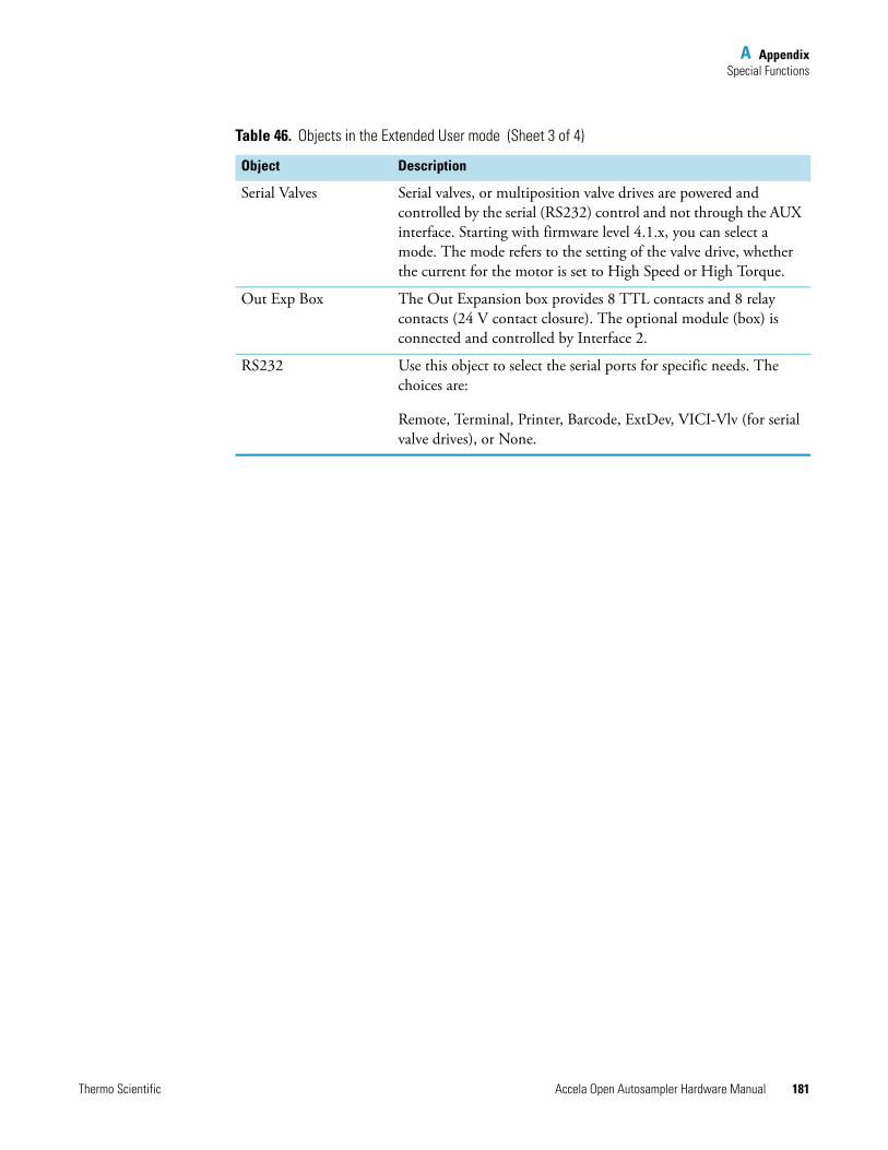
A AppendixSpecial Functions
Thermo Scientific Accela Open Autosampler Hardware Manual 181
Serial Valves Serial valves, or multiposition valve drives are powered and controlled by the serial (RS232) control and not through the AUX interface. Starting with firmware level 4.1.x, you can select a mode. The mode refers to the setting of the valve drive, whether the current for the motor is set to High Speed or High Torque.
Out Exp Box The Out Expansion box provides 8 TTL contacts and 8 relay contacts (24 V contact closure). The optional module (box) is connected and controlled by Interface 2.
RS232 Use this object to select the serial ports for specific needs. The choices are:
Remote, Terminal, Printer, Barcode, ExtDev, VICI-Vlv (for serial valve drives), or None.
Table 46. Objects in the Extended User mode (Sheet 3 of 4)
Object Description
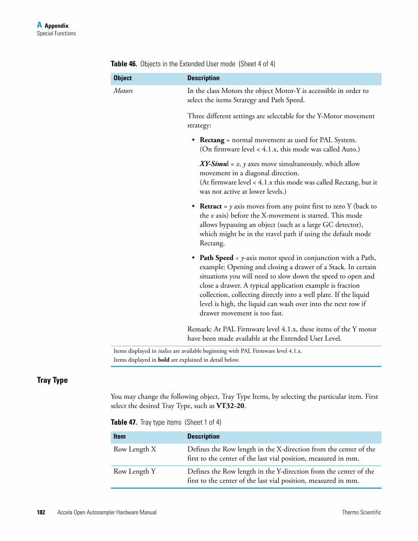
A AppendixSpecial Functions
182 Accela Open Autosampler Hardware Manual Thermo Scientific
Tray Type
You may change the following object, Tray Type Items, by selecting the particular item. First select the desired Tray Type, such as VT32-20.
Motors In the class Motors the object Motor-Y is accessible in order to select the items Strategy and Path Speed.
Three different settings are selectable for the Y-Motor movement strategy:
• Rectang = normal movement as used for PAL System. (On firmware level < 4.1.x, this mode was called Auto.)
XY-Simul = x, y axes move simultaneously, which allow movement in a diagonal direction. (At firmware level < 4.1.x this mode was called Rectang, but it was not active at lower levels.)
• Retract = y axis moves from any point first to zero Y (back to the x axis) before the X-movement is started. This mode allows bypassing an object (such as a large GC detector), which might be in the travel path if using the default mode Rectang.
• Path Speed = y-axis motor speed in conjunction with a Path, example: Opening and closing a drawer of a Stack. In certain situations you will need to slow down the speed to open and close a drawer. A typical application example is fraction collection, collecting directly into a well plate. If the liquid level is high, the liquid can wash over into the next row if drawer movement is too fast.
Remark: At PAL Firmware level 4.1.x, these items of the Y motor have been made available at the Extended User Level.
Items displayed in italics are available beginning with PAL Firmware level 4.1.x.Items displayed in bold are explained in detail below.
Table 46. Objects in the Extended User mode (Sheet 4 of 4)
Object Description
Table 47. Tray type items (Sheet 1 of 4)
Item Description
Row Length X Defines the Row length in the X-direction from the center of the first to the center of the last vial position, measured in mm.
Row Length Y Defines the Row length in the Y-direction from the center of the first to the center of the last vial position, measured in mm.
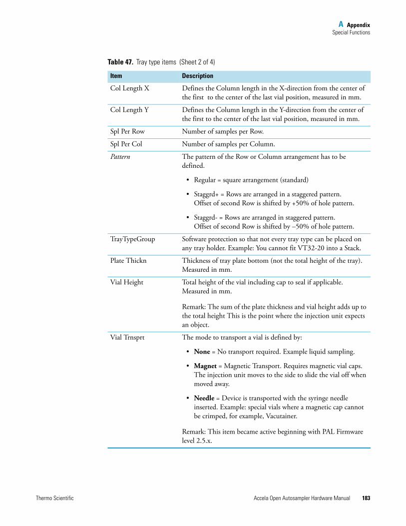
A AppendixSpecial Functions
Thermo Scientific Accela Open Autosampler Hardware Manual 183
Col Length X Defines the Column length in the X-direction from the center of the first to the center of the last vial position, measured in mm.
Col Length Y Defines the Column length in the Y-direction from the center of the first to the center of the last vial position, measured in mm.
Spl Per Row Number of samples per Row.
Spl Per Col Number of samples per Column.
Pattern The pattern of the Row or Column arrangement has to be defined.
• Regular = square arrangement (standard)
• Staggrd+ = Rows are arranged in a staggered pattern. Offset of second Row is shifted by +50% of hole pattern.
• Staggrd- = Rows are arranged in staggered pattern. Offset of second Row is shifted by –50% of hole pattern.
TrayTypeGroup Software protection so that not every tray type can be placed on any tray holder. Example: You cannot fit VT32-20 into a Stack.
Plate Thickn Thickness of tray plate bottom (not the total height of the tray). Measured in mm.
Vial Height Total height of the vial including cap to seal if applicable. Measured in mm.
Remark: The sum of the plate thickness and vial height adds up to the total height This is the point where the injection unit expects an object.
Vial Trnsprt The mode to transport a vial is defined by:
• None = No transport required. Example liquid sampling.
• Magnet = Magnetic Transport. Requires magnetic vial caps. The injection unit moves to the side to slide the vial off when moved away.
• Needle = Device is transported with the syringe needle inserted. Example: special vials where a magnetic cap cannot be crimped, for example, Vacutainer.
Remark: This item became active beginning with PAL Firmware level 2.5.x.
Table 47. Tray type items (Sheet 2 of 4)
Item Description
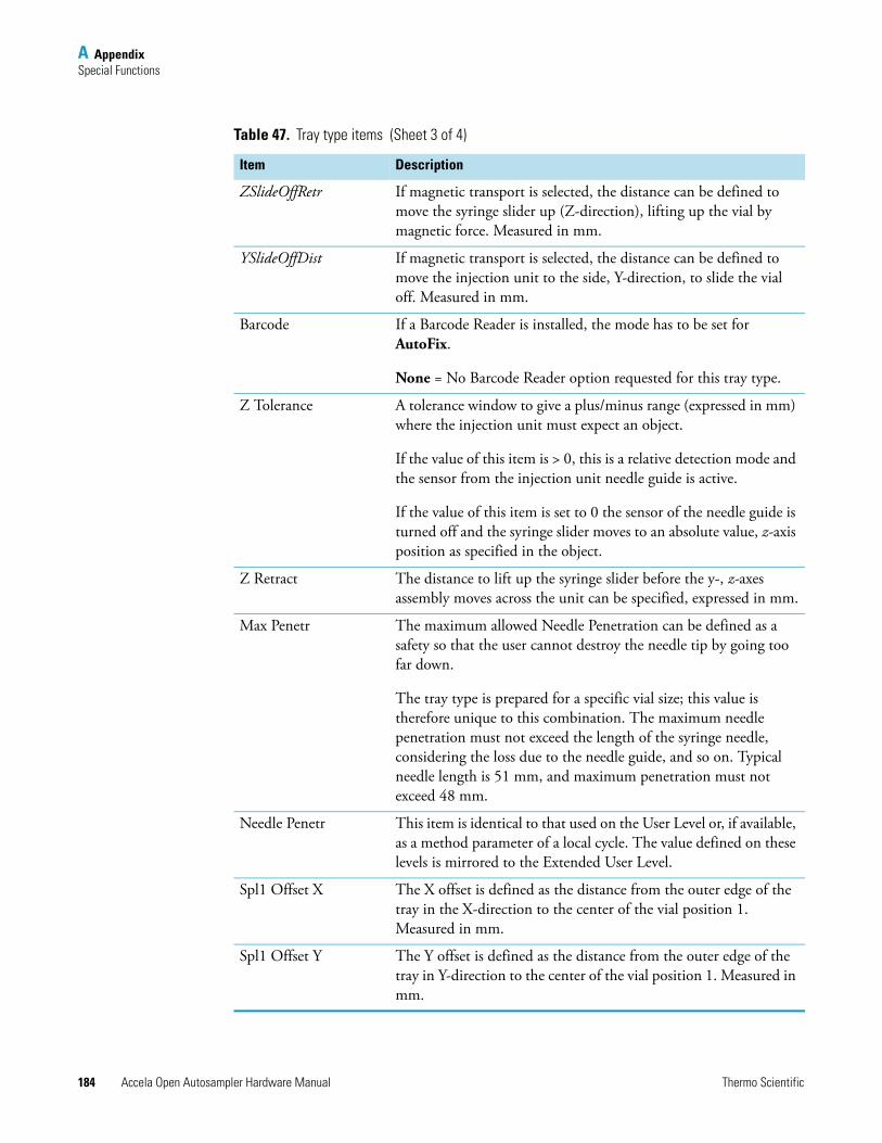
A AppendixSpecial Functions
184 Accela Open Autosampler Hardware Manual Thermo Scientific
ZSlideOffRetr If magnetic transport is selected, the distance can be defined to move the syringe slider up (Z-direction), lifting up the vial by magnetic force. Measured in mm.
YSlideOffDist If magnetic transport is selected, the distance can be defined to move the injection unit to the side, Y-direction, to slide the vial off. Measured in mm.
Barcode If a Barcode Reader is installed, the mode has to be set for AutoFix.
None = No Barcode Reader option requested for this tray type.
Z Tolerance A tolerance window to give a plus/minus range (expressed in mm) where the injection unit must expect an object.
If the value of this item is > 0, this is a relative detection mode and the sensor from the injection unit needle guide is active.
If the value of this item is set to 0 the sensor of the needle guide is turned off and the syringe slider moves to an absolute value, z-axis position as specified in the object.
Z Retract The distance to lift up the syringe slider before the y-, z-axes assembly moves across the unit can be specified, expressed in mm.
Max Penetr The maximum allowed Needle Penetration can be defined as a safety so that the user cannot destroy the needle tip by going too far down.
The tray type is prepared for a specific vial size; this value is therefore unique to this combination. The maximum needle penetration must not exceed the length of the syringe needle, considering the loss due to the needle guide, and so on. Typical needle length is 51 mm, and maximum penetration must not exceed 48 mm.
Needle Penetr This item is identical to that used on the User Level or, if available, as a method parameter of a local cycle. The value defined on these levels is mirrored to the Extended User Level.
Spl1 Offset X The X offset is defined as the distance from the outer edge of the tray in the X-direction to the center of the vial position 1. Measured in mm.
Spl1 Offset Y The Y offset is defined as the distance from the outer edge of the tray in Y-direction to the center of the vial position 1. Measured in mm.
Table 47. Tray type items (Sheet 3 of 4)
Item Description
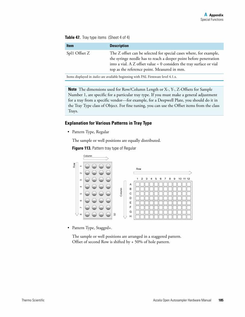
A AppendixSpecial Functions
Thermo Scientific Accela Open Autosampler Hardware Manual 185
Explanation for Various Patterns in Tray Type
• Pattern Type, Regular
The sample or well positions are equally distributed.
Figure 113. Pattern tray type of Regular
• Pattern Type, Staggrd+.
The sample or well positions are arranged in a staggered pattern.Offset of second Row is shifted by + 50% of hole pattern.
Spl1 Offset Z The Z offset can be selected for special cases where, for example, the syringe needle has to reach a deeper point before penetration into a vial. A Z offset value = 0 considers the tray surface or vial top as the reference point. Measured in mm.
Items displayed in italics are available beginning with PAL Firmware level 4.1.x.
Note The dimensions used for Row/Column Length or X-, Y-, Z-Offsets for Sample Number 1, are specific for a particular tray type. If you must make a general adjustment for a tray from a specific vendor—for example, for a Deepwell Plate, you should do it in the Tray Type class of Object. For fine tuning, you can use the Offset items from the class Trays.
Table 47. Tray type items (Sheet 4 of 4)
Item Description
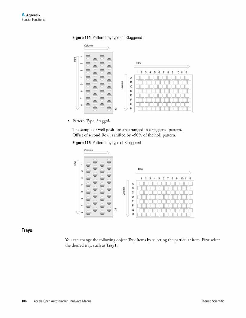
A AppendixSpecial Functions
186 Accela Open Autosampler Hardware Manual Thermo Scientific
Figure 114. Pattern tray type -of Staggered+
• Pattern Type, Staggrd-.
The sample or well positions are arranged in a staggered pattern. Offset of second Row is shifted by –50% of the hole pattern.
Figure 115. Pattern tray type of Staggered-
Trays
You can change the following object Tray Items by selecting the particular item. First select the desired tray, such as Tray1.
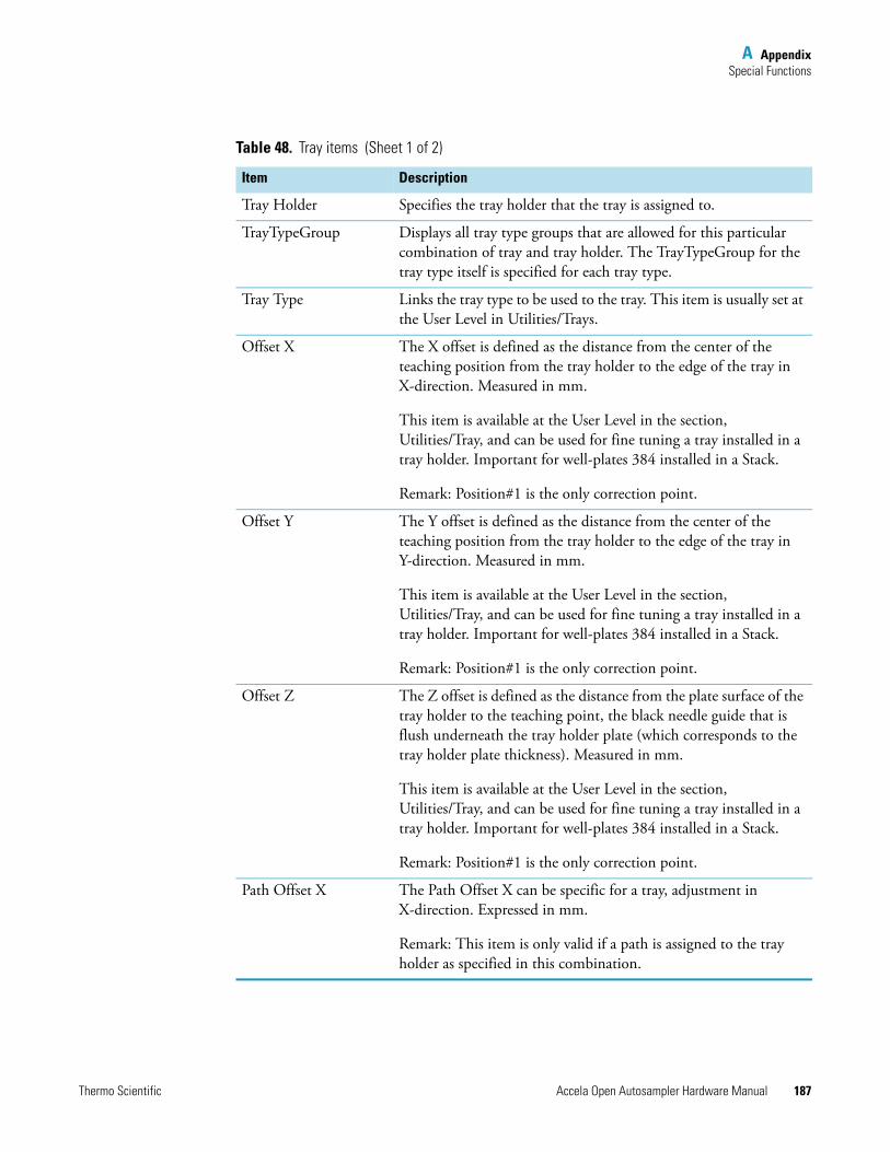
A AppendixSpecial Functions
Thermo Scientific Accela Open Autosampler Hardware Manual 187
Table 48. Tray items (Sheet 1 of 2)
Item Description
Tray Holder Specifies the tray holder that the tray is assigned to.
TrayTypeGroup Displays all tray type groups that are allowed for this particular combination of tray and tray holder. The TrayTypeGroup for the tray type itself is specified for each tray type.
Tray Type Links the tray type to be used to the tray. This item is usually set at the User Level in Utilities/Trays.
Offset X The X offset is defined as the distance from the center of the teaching position from the tray holder to the edge of the tray in X-direction. Measured in mm.
This item is available at the User Level in the section, Utilities/Tray, and can be used for fine tuning a tray installed in a tray holder. Important for well-plates 384 installed in a Stack.
Remark: Position#1 is the only correction point.
Offset Y The Y offset is defined as the distance from the center of the teaching position from the tray holder to the edge of the tray in Y-direction. Measured in mm.
This item is available at the User Level in the section, Utilities/Tray, and can be used for fine tuning a tray installed in a tray holder. Important for well-plates 384 installed in a Stack.
Remark: Position#1 is the only correction point.
Offset Z The Z offset is defined as the distance from the plate surface of the tray holder to the teaching point, the black needle guide that is flush underneath the tray holder plate (which corresponds to the tray holder plate thickness). Measured in mm.
This item is available at the User Level in the section, Utilities/Tray, and can be used for fine tuning a tray installed in a tray holder. Important for well-plates 384 installed in a Stack.
Remark: Position#1 is the only correction point.
Path Offset X The Path Offset X can be specific for a tray, adjustment in X-direction. Expressed in mm.
Remark: This item is only valid if a path is assigned to the tray holder as specified in this combination.
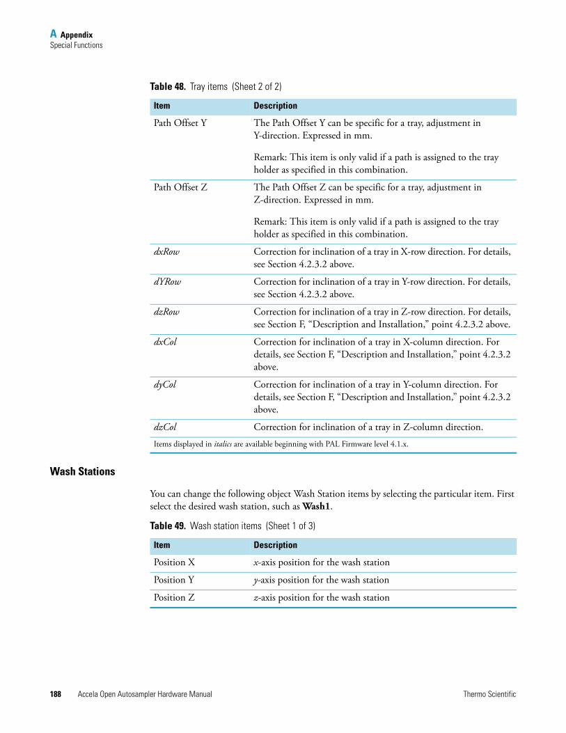
A AppendixSpecial Functions
188 Accela Open Autosampler Hardware Manual Thermo Scientific
Wash Stations
You can change the following object Wash Station items by selecting the particular item. First select the desired wash station, such as Wash1.
Path Offset Y The Path Offset Y can be specific for a tray, adjustment in Y-direction. Expressed in mm.
Remark: This item is only valid if a path is assigned to the tray holder as specified in this combination.
Path Offset Z The Path Offset Z can be specific for a tray, adjustment in Z-direction. Expressed in mm.
Remark: This item is only valid if a path is assigned to the tray holder as specified in this combination.
dxRow Correction for inclination of a tray in X-row direction. For details, see Section 4.2.3.2 above.
dYRow Correction for inclination of a tray in Y-row direction. For details, see Section 4.2.3.2 above.
dzRow Correction for inclination of a tray in Z-row direction. For details, see Section F, “Description and Installation,” point 4.2.3.2 above.
dxCol Correction for inclination of a tray in X-column direction. For details, see Section F, “Description and Installation,” point 4.2.3.2 above.
dyCol Correction for inclination of a tray in Y-column direction. For details, see Section F, “Description and Installation,” point 4.2.3.2 above.
dzCol Correction for inclination of a tray in Z-column direction.
Items displayed in italics are available beginning with PAL Firmware level 4.1.x.
Table 48. Tray items (Sheet 2 of 2)
Item Description
Table 49. Wash station items (Sheet 1 of 3)
Item Description
Position X x-axis position for the wash station
Position Y y-axis position for the wash station
Position Z z-axis position for the wash station
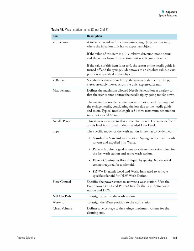
A AppendixSpecial Functions
Thermo Scientific Accela Open Autosampler Hardware Manual 189
Z Tolerance A tolerance window for a plus/minus range (expressed in mm) where the injection unit has to expect an object.
If the value of this item is > 0, a relative detection mode occurs and the sensor from the injection unit needle guide is active.
If the value of this item is set to 0, the sensor of the needle guide is turned off and the syringe slider moves to an absolute value, z-axis position as specified in the object.
Z Retract Specifies the distance to lift up the syringe slider before the y-, z-axes assembly moves across the unit, expressed in mm.
Max Penetrat Defines the maximum allowed Needle Penetration as a safety so that the user cannot destroy the needle tip by going too far down.
The maximum needle penetration must not exceed the length of the syringe needle, considering the loss due to the needle guide and so on. Typical needle length is 51 mm; maximum penetration must not exceed 48 mm.
Needle Penetr This item is identical to that at the User Level. The value defined at this level is mirrored in the Extended User Level.
Type The specific mode for the wash station in use has to be defined:
• Standard = Standard wash station. Syringe is filled with wash solvent and expelled into Waste.
• Pulse = A pulsed signal is sent to activate the device. Used for the fast wash station and active wash station.
• Flow = Continuous flow of liquid by gravity. No electrical contact required for a solenoid.
• DLW = Dynamic Load and Wash. Item used to activate specific solenoid for DLW Wash Station.
Flow Control Specifies the power source to activate a wash station. Uses the Event Power-Out1 and Power-Out2 for the Fast, Active wash station and DLW.
Ndl Cln Path To assign a path to the wash station.
Waste to To assign the Waste position to the wash station.
Clean Volume Defines a percentage of the syringe maximum volume for the cleaning step.
Table 49. Wash station items (Sheet 2 of 3)
Item Description
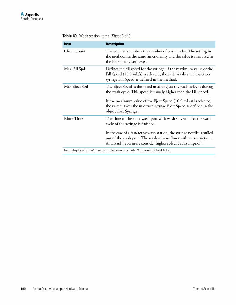
A AppendixSpecial Functions
190 Accela Open Autosampler Hardware Manual Thermo Scientific
Clean Count The counter monitors the number of wash cycles. The setting in the method has the same functionality and the value is mirrored in the Extended User Level.
Max Fill Spd Defines the fill speed for the syringe. If the maximum value of the Fill Speed (10.0 mL/s) is selected, the system takes the injection syringe Fill Speed as defined in the method.
Max Eject Spd The Eject Speed is the speed used to eject the wash solvent during the wash cycle. This speed is usually higher than the Fill Speed.
If the maximum value of the Eject Speed (10.0 mL/s) is selected, the system takes the injection syringe Eject Speed as defined in the object class Syringe.
Rinse Time The time to rinse the wash port with wash solvent after the wash cycle of the syringe is finished.
In the case of a fast/active wash station, the syringe needle is pulled out of the wash port. The wash solvent flows without restriction. As a result, you must consider higher solvent consumption.
Items displayed in italics are available beginning with PAL Firmware level 4.1.x.
Table 49. Wash station items (Sheet 3 of 3)
Item Description
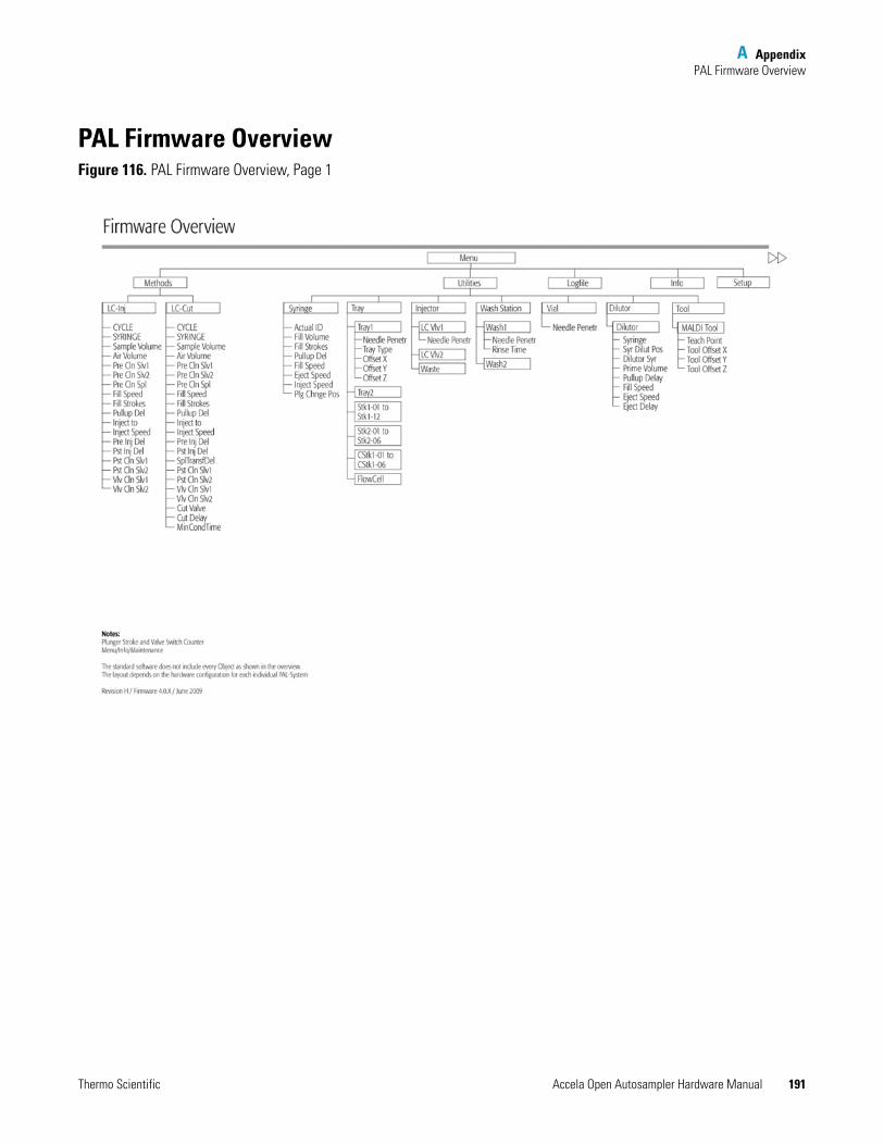
A AppendixPAL Firmware Overview
Thermo Scientific Accela Open Autosampler Hardware Manual 191
PAL Firmware OverviewFigure 116. PAL Firmware Overview, Page 1
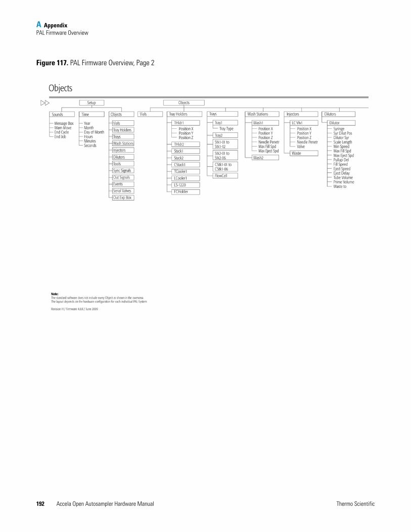
A AppendixPAL Firmware Overview
192 Accela Open Autosampler Hardware Manual Thermo Scientific
Figure 117. PAL Firmware Overview, Page 2
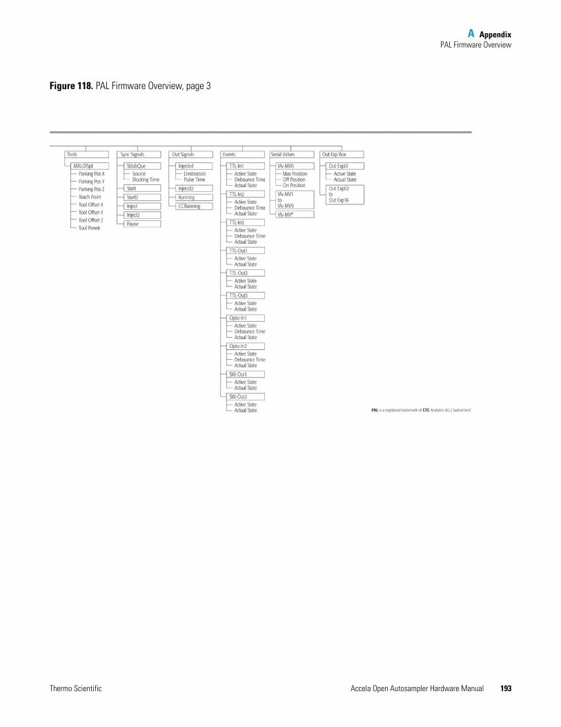
A AppendixPAL Firmware Overview
Thermo Scientific Accela Open Autosampler Hardware Manual 193
Figure 118. PAL Firmware Overview, page 3
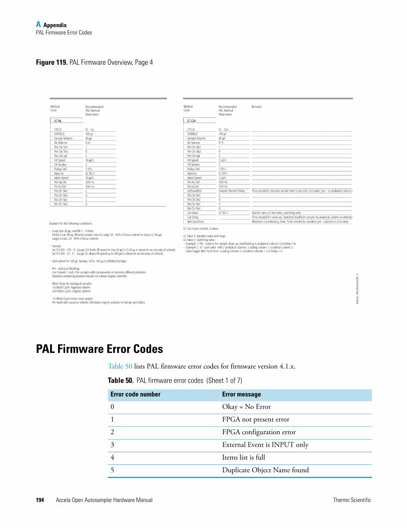
A AppendixPAL Firmware Error Codes
194 Accela Open Autosampler Hardware Manual Thermo Scientific
Figure 119. PAL Firmware Overview, Page 4
PAL Firmware Error CodesTable 50 lists PAL firmware error codes for firmware version 4.1.x.
Table 50. PAL firmware error codes (Sheet 1 of 7)
Error code number Error message
0 Okay = No Error
1 FPGA not present error
2 FPGA configuration error
3 External Event is INPUT only
4 Items list is full
5 Duplicate Object Name found
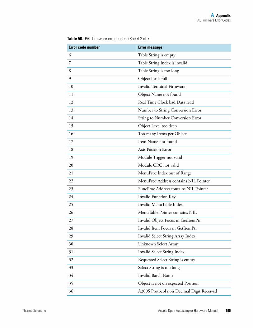
A AppendixPAL Firmware Error Codes
Thermo Scientific Accela Open Autosampler Hardware Manual 195
6 Table String is empty
7 Table String Index is invalid
8 Table String is too long
9 Object list is full
10 Invalid Terminal Firmware
11 Object Name not found
12 Real Time Clock bad Data read
13 Number to String Conversion Error
14 String to Number Conversion Error
15 Object Level too deep
16 Too many Items per Object
17 Item Name not found
18 Axis Position Error
19 Module Trigger not valid
20 Module CRC not valid
21 MenuProc Index out of Range
22 MenuProc Address contains NIL Pointer
23 FuncProc Address contains NIL Pointer
24 Invalid Function Key
25 Invalid MenuTable Index
26 MenuTable Pointer contains NIL
27 Invalid Object Focus in GetItemPtr
28 Invalid Item Focus in GetItemPtr
29 Invalid Select String Array Index
30 Unknown Select Array
31 Invalid Select String Index
32 Requested Select String is empty
33 Select String is too long
34 Invalid Batch Name
35 Object is not on expected Position
36 A200S Protocol non Decimal Digit Received
Table 50. PAL firmware error codes (Sheet 2 of 7)
Error code number Error message
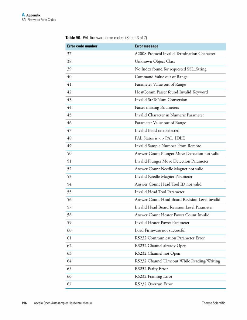
A AppendixPAL Firmware Error Codes
196 Accela Open Autosampler Hardware Manual Thermo Scientific
37 A200S Protocol invalid Termination Character
38 Unknown Object Class
39 No Index found for requested SSL_String
40 Command Value out of Range
41 Parameter Value out of Range
42 HostComm Parser found Invalid Keyword
43 Invalid StrToNum Conversion
44 Parser missing Parameters
45 Invalid Character in Numeric Parameter
46 Parameter Value out of Range
47 Invalid Baud rate Selected
48 PAL Status is < > PAL_IDLE
49 Invalid Sample Number From Remote
50 Answer Count Plunger Move Detection not valid
51 Invalid Plunger Move Detection Parameter
52 Answer Count Needle Magnet not valid
53 Invalid Needle Magnet Parameter
54 Answer Count Head Tool ID not valid
55 Invalid Head Tool Parameter
56 Answer Count Head Board Revision Level invalid
57 Invalid Head Board Revision Level Parameter
58 Answer Count Heater Power Count Invalid
59 Invalid Heater Power Parameter
60 Load Firmware not successful
61 RS232 Communication Parameter Error
62 RS232 Channel already Open
63 RS232 Channel not Open
64 RS232 Channel Timeout While Reading/Writing
65 RS232 Parity Error
66 RS232 Framing Error
67 RS232 Overrun Error
Table 50. PAL firmware error codes (Sheet 3 of 7)
Error code number Error message
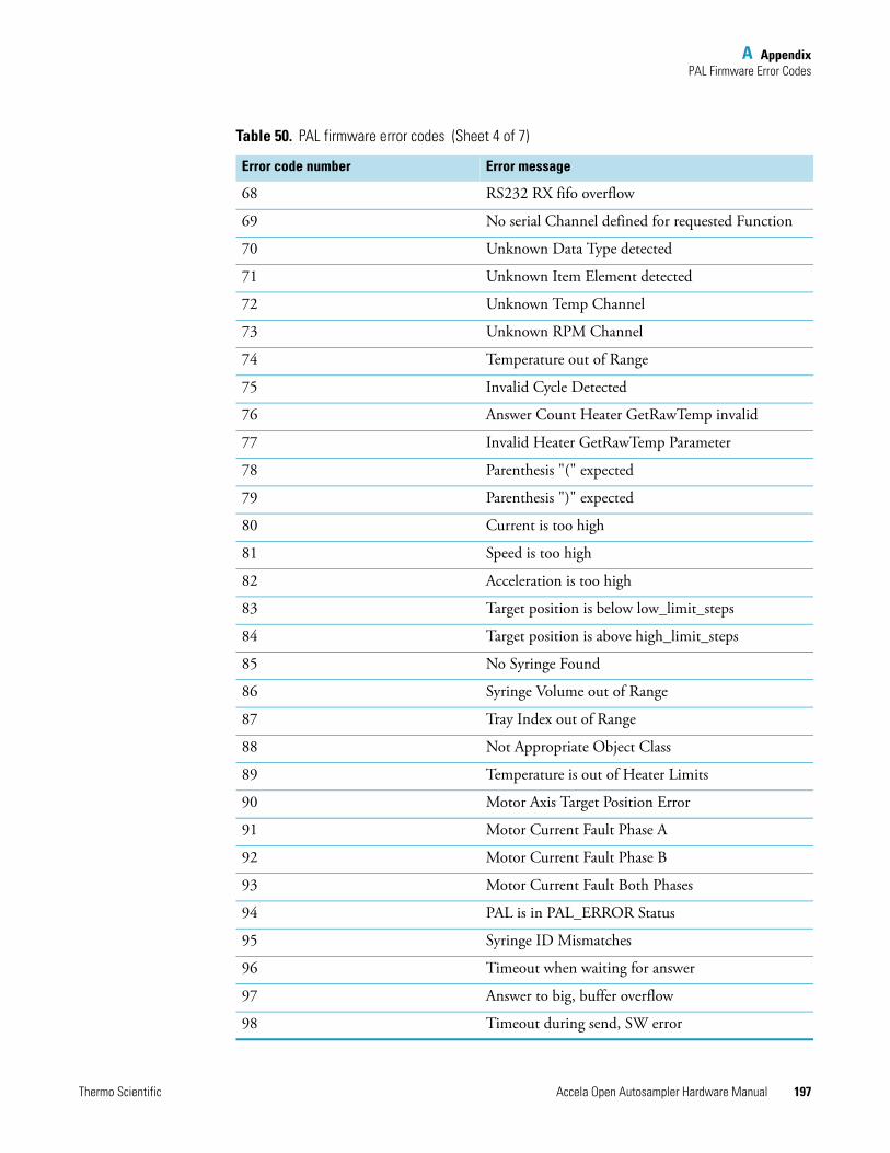
A AppendixPAL Firmware Error Codes
Thermo Scientific Accela Open Autosampler Hardware Manual 197
68 RS232 RX fifo overflow
69 No serial Channel defined for requested Function
70 Unknown Data Type detected
71 Unknown Item Element detected
72 Unknown Temp Channel
73 Unknown RPM Channel
74 Temperature out of Range
75 Invalid Cycle Detected
76 Answer Count Heater GetRawTemp invalid
77 Invalid Heater GetRawTemp Parameter
78 Parenthesis "(" expected
79 Parenthesis ")" expected
80 Current is too high
81 Speed is too high
82 Acceleration is too high
83 Target position is below low_limit_steps
84 Target position is above high_limit_steps
85 No Syringe Found
86 Syringe Volume out of Range
87 Tray Index out of Range
88 Not Appropriate Object Class
89 Temperature is out of Heater Limits
90 Motor Axis Target Position Error
91 Motor Current Fault Phase A
92 Motor Current Fault Phase B
93 Motor Current Fault Both Phases
94 PAL is in PAL_ERROR Status
95 Syringe ID Mismatches
96 Timeout when waiting for answer
97 Answer to big, buffer overflow
98 Timeout during send, SW error
Table 50. PAL firmware error codes (Sheet 4 of 7)
Error code number Error message
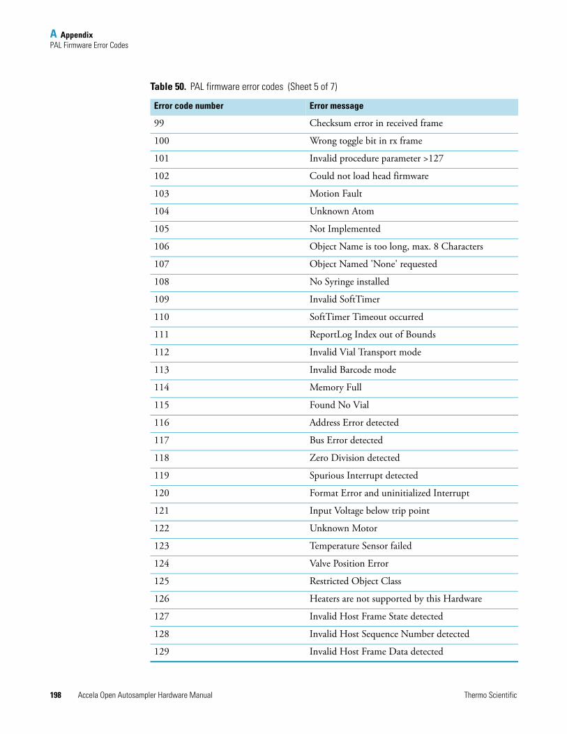
A AppendixPAL Firmware Error Codes
198 Accela Open Autosampler Hardware Manual Thermo Scientific
99 Checksum error in received frame
100 Wrong toggle bit in rx frame
101 Invalid procedure parameter >127
102 Could not load head firmware
103 Motion Fault
104 Unknown Atom
105 Not Implemented
106 Object Name is too long, max. 8 Characters
107 Object Named 'None' requested
108 No Syringe installed
109 Invalid SoftTimer
110 SoftTimer Timeout occurred
111 ReportLog Index out of Bounds
112 Invalid Vial Transport mode
113 Invalid Barcode mode
114 Memory Full
115 Found No Vial
116 Address Error detected
117 Bus Error detected
118 Zero Division detected
119 Spurious Interrupt detected
120 Format Error and uninitialized Interrupt
121 Input Voltage below trip point
122 Unknown Motor
123 Temperature Sensor failed
124 Valve Position Error
125 Restricted Object Class
126 Heaters are not supported by this Hardware
127 Invalid Host Frame State detected
128 Invalid Host Sequence Number detected
129 Invalid Host Frame Data detected
Table 50. PAL firmware error codes (Sheet 5 of 7)
Error code number Error message
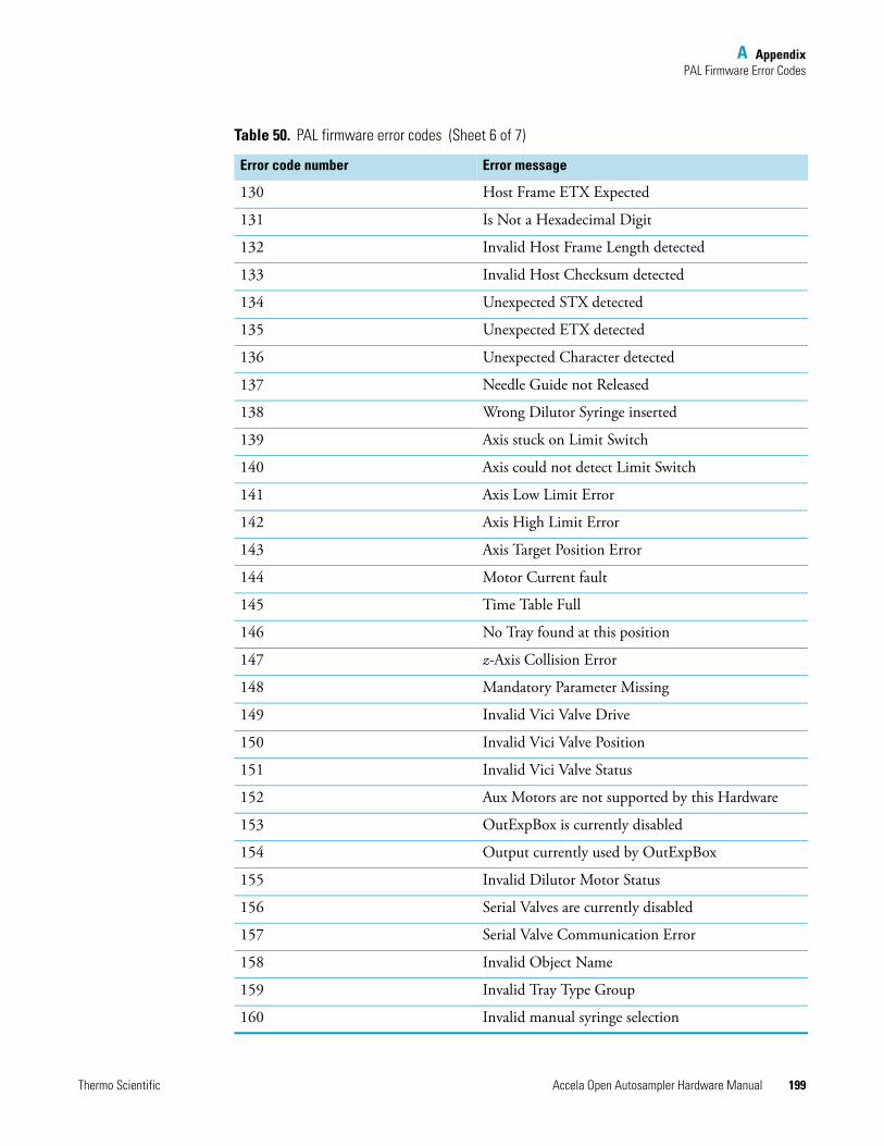
A AppendixPAL Firmware Error Codes
Thermo Scientific Accela Open Autosampler Hardware Manual 199
130 Host Frame ETX Expected
131 Is Not a Hexadecimal Digit
132 Invalid Host Frame Length detected
133 Invalid Host Checksum detected
134 Unexpected STX detected
135 Unexpected ETX detected
136 Unexpected Character detected
137 Needle Guide not Released
138 Wrong Dilutor Syringe inserted
139 Axis stuck on Limit Switch
140 Axis could not detect Limit Switch
141 Axis Low Limit Error
142 Axis High Limit Error
143 Axis Target Position Error
144 Motor Current fault
145 Time Table Full
146 No Tray found at this position
147 z-Axis Collision Error
148 Mandatory Parameter Missing
149 Invalid Vici Valve Drive
150 Invalid Vici Valve Position
151 Invalid Vici Valve Status
152 Aux Motors are not supported by this Hardware
153 OutExpBox is currently disabled
154 Output currently used by OutExpBox
155 Invalid Dilutor Motor Status
156 Serial Valves are currently disabled
157 Serial Valve Communication Error
158 Invalid Object Name
159 Invalid Tray Type Group
160 Invalid manual syringe selection
Table 50. PAL firmware error codes (Sheet 6 of 7)
Error code number Error message
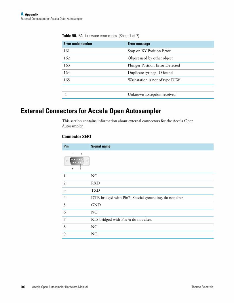
A AppendixExternal Connectors for Accela Open Autosampler
200 Accela Open Autosampler Hardware Manual Thermo Scientific
External Connectors for Accela Open AutosamplerThis section contains information about external connectors for the Accela Open Autosampler.
Connector SER1
161 Stop on XY Position Error
162 Object used by other object
163 Plunger Position Error Detected
164 Duplicate syringe ID found
165 Washstation is not of type DLW
-1 Unknown Exception received
Table 50. PAL firmware error codes (Sheet 7 of 7)
Error code number Error message
Pin Signal name
1 NC
2 RXD
3 TXD
4 DTR bridged with Pin7; Special grounding, do not alter.
5 GND
6 NC
7 RTS bridged with Pin 4; do not alter.
8 NC
9 NC

A AppendixExternal Connectors for Accela Open Autosampler
Thermo Scientific Accela Open Autosampler Hardware Manual 201
Connector TERMINAL or SER3
Connector SER2
Pin Signal name
1 GND
2 RXD
3 TXD
4 NC
5 NC
6 +5V
7 NC
8 GND
Pin Signal name
1 GND
2 RXD
3 TXD
4 NC
5 NC
6 +5V
7 NC
8 GND
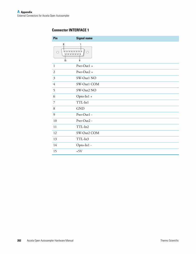
A AppendixExternal Connectors for Accela Open Autosampler
202 Accela Open Autosampler Hardware Manual Thermo Scientific
Connector INTERFACE 1
Pin Signal name
1 Pwr-Out1 +
2 Pwr-Out2 +
3 SW-Out1 NO
4 SW-Out1 COM
5 SW-Out2 NO
6 Opto-In1 +
7 TTL-In1
8 GND
9 Pwr-Out1 -
10 Pwr-Out2 -
11 TTL-In2
12 SW-Out2 COM
13 TTL-In3
14 Opto-In1 -
15 +5V
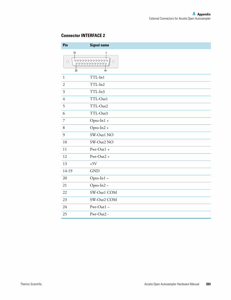
A AppendixExternal Connectors for Accela Open Autosampler
Thermo Scientific Accela Open Autosampler Hardware Manual 203
Connector INTERFACE 2
Pin Signal name
1 TTL-In1
2 TTL-In2
3 TTL-In3
4 TTL-Out1
5 TTL-Out2
6 TTL-Out3
7 Opto-In1 +
8 Opto-In2 +
9 SW-Out1 NO
10 SW-Out2 NO
11 Pwr-Out1 +
12 Pwr-Out2 +
13 +5V
14-19 GND
20 Opto-In1 –
21 Opto-In2 –
22 SW-Out1 COM
23 SW-Out2 COM
24 Pwr-Out1 –
25 Pwr-Out2 -
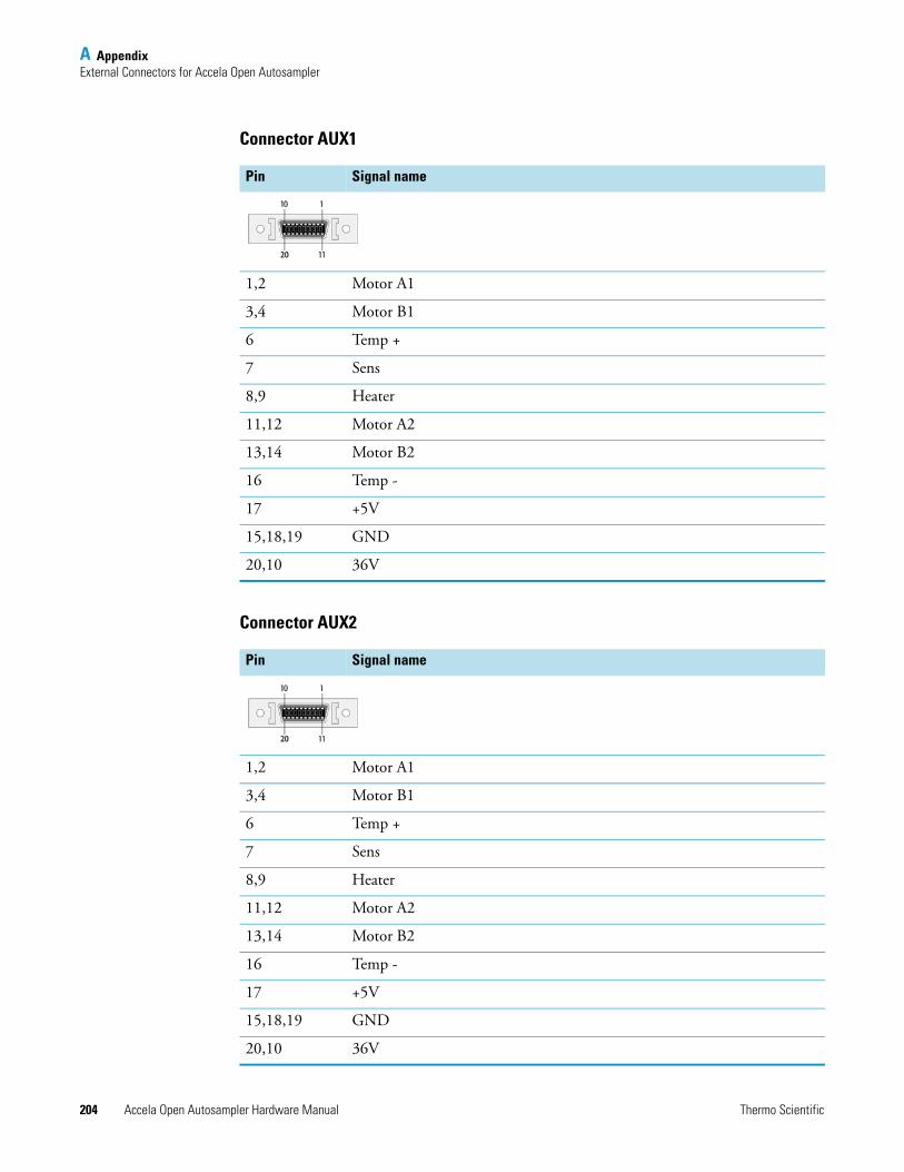
A AppendixExternal Connectors for Accela Open Autosampler
204 Accela Open Autosampler Hardware Manual Thermo Scientific
Connector AUX1
Connector AUX2
Pin Signal name
1,2 Motor A1
3,4 Motor B1
6 Temp +
7 Sens
8,9 Heater
11,12 Motor A2
13,14 Motor B2
16 Temp -
17 +5V
15,18,19 GND
20,10 36V
Pin Signal name
1,2 Motor A1
3,4 Motor B1
6 Temp +
7 Sens
8,9 Heater
11,12 Motor A2
13,14 Motor B2
16 Temp -
17 +5V
15,18,19 GND
20,10 36V
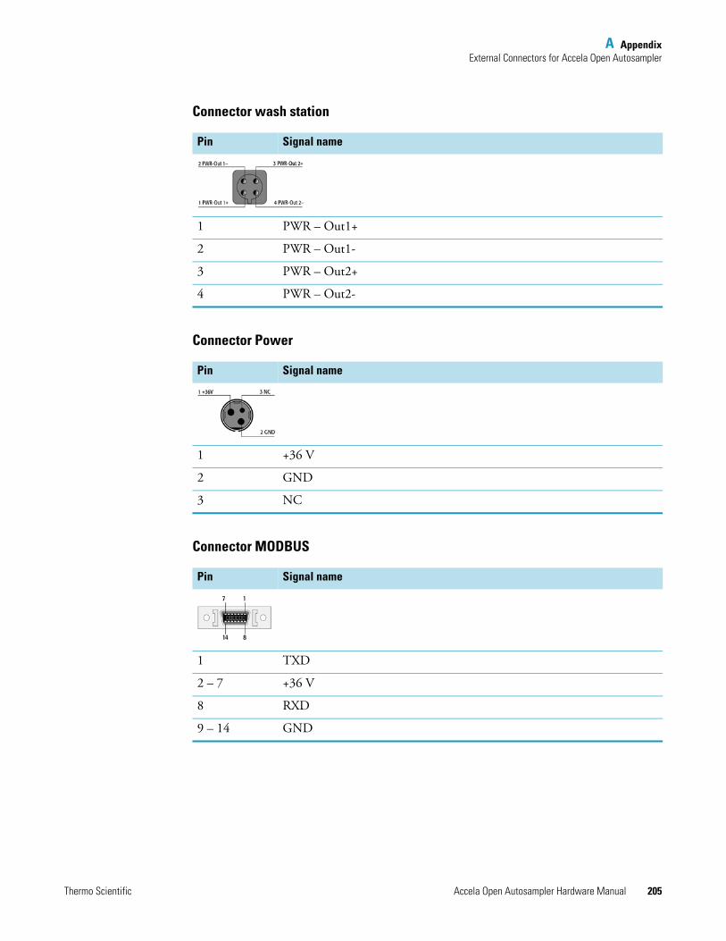
A AppendixExternal Connectors for Accela Open Autosampler
Thermo Scientific Accela Open Autosampler Hardware Manual 205
Connector wash station
Connector Power
Connector MODBUS
Pin Signal name
1 PWR – Out1+
2 PWR – Out1-
3 PWR – Out2+
4 PWR – Out2-
Pin Signal name
1 +36 V
2 GND
3 NC
Pin Signal name
1 TXD
2 – 7 +36 V
8 RXD
9 – 14 GND
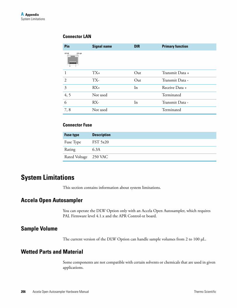
A AppendixSystem Limitations
206 Accela Open Autosampler Hardware Manual Thermo Scientific
Connector LAN
Connector Fuse
System LimitationsThis section contains information about system limitations.
Accela Open Autosampler
You can operate the DLW Option only with an Accela Open Autosampler, which requires PAL Firmware level 4.1.x and the APR Control-xt board.
Sample Volume
The current version of the DLW Option can handle sample volumes from 2 to 100 μL.
Wetted Parts and Material
Some components are not compatible with certain solvents or chemicals that are used in given applications.
Pin Signal name DIR Primary function
1 TX+ Out Transmit Data +
2 TX- Out Transmit Data -
3 RX+ In Receive Data +
4, 5 Not used Terminated
6 RX- In Transmit Data -
7, 8 Not used Terminated
Fuse type Description
Fuse Type FST 5x20
Rating 6.3A
Rated Voltage 250 VAC
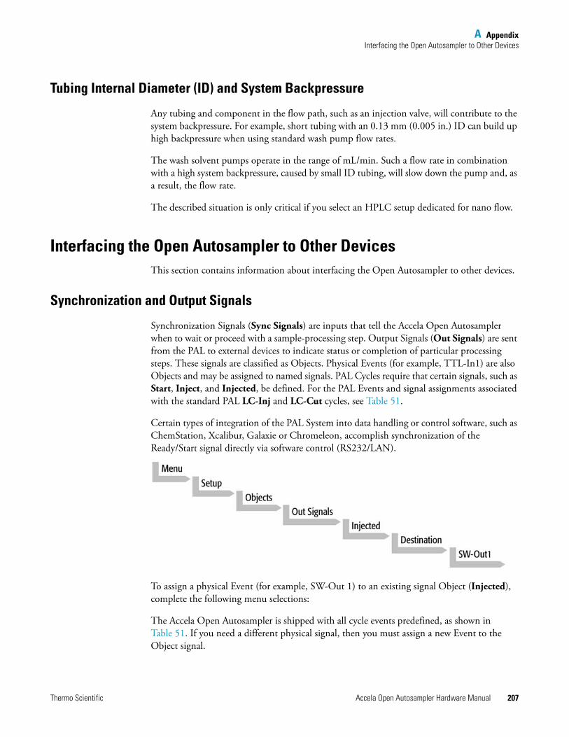
A AppendixInterfacing the Open Autosampler to Other Devices
Thermo Scientific Accela Open Autosampler Hardware Manual 207
Tubing Internal Diameter (ID) and System Backpressure
Any tubing and component in the flow path, such as an injection valve, will contribute to the system backpressure. For example, short tubing with an 0.13 mm (0.005 in.) ID can build up high backpressure when using standard wash pump flow rates.
The wash solvent pumps operate in the range of mL/min. Such a flow rate in combination with a high system backpressure, caused by small ID tubing, will slow down the pump and, as a result, the flow rate.
The described situation is only critical if you select an HPLC setup dedicated for nano flow.
Interfacing the Open Autosampler to Other DevicesThis section contains information about interfacing the Open Autosampler to other devices.
Synchronization and Output Signals
Synchronization Signals (Sync Signals) are inputs that tell the Accela Open Autosampler when to wait or proceed with a sample-processing step. Output Signals (Out Signals) are sent from the PAL to external devices to indicate status or completion of particular processing steps. These signals are classified as Objects. Physical Events (for example, TTL-In1) are also Objects and may be assigned to named signals. PAL Cycles require that certain signals, such as Start, Inject, and Injected, be defined. For the PAL Events and signal assignments associated with the standard PAL LC-Inj and LC-Cut cycles, see Table 51.
Certain types of integration of the PAL System into data handling or control software, such as ChemStation, Xcalibur, Galaxie or Chromeleon, accomplish synchronization of the Ready/Start signal directly via software control (RS232/LAN).
To assign a physical Event (for example, SW-Out 1) to an existing signal Object (Injected), complete the following menu selections:
The Accela Open Autosampler is shipped with all cycle events predefined, as shown in Table 51. If you need a different physical signal, then you must assign a new Event to the Object signal.
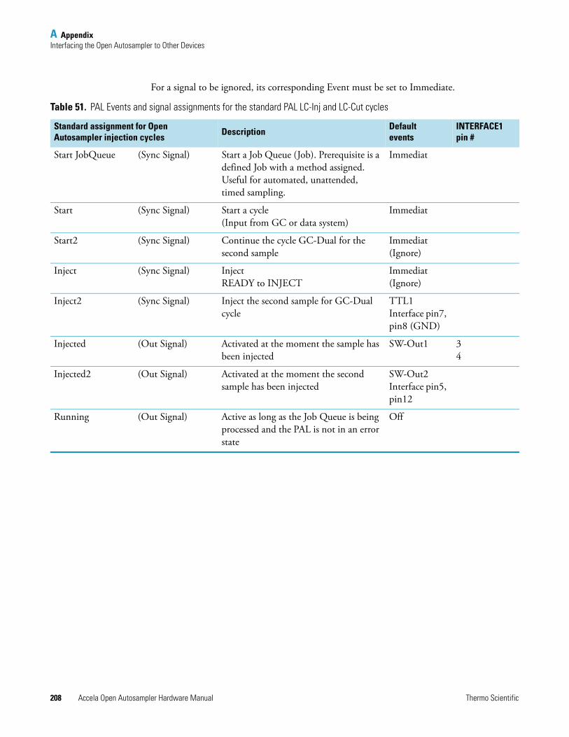
A AppendixInterfacing the Open Autosampler to Other Devices
208 Accela Open Autosampler Hardware Manual Thermo Scientific
For a signal to be ignored, its corresponding Event must be set to Immediate.
Table 51. PAL Events and signal assignments for the standard PAL LC-Inj and LC-Cut cycles
Standard assignment for Open Autosampler injection cycles Description Default
eventsINTERFACE1 pin #
Start JobQueue (Sync Signal) Start a Job Queue (Job). Prerequisite is a defined Job with a method assigned. Useful for automated, unattended, timed sampling.
Immediat
Start (Sync Signal) Start a cycle (Input from GC or data system)
Immediat
Start2 (Sync Signal) Continue the cycle GC-Dual for the second sample
Immediat(Ignore)
Inject (Sync Signal) InjectREADY to INJECT
Immediat(Ignore)
Inject2 (Sync Signal) Inject the second sample for GC-Dual cycle
TTL1Interface pin7, pin8 (GND)
Injected (Out Signal) Activated at the moment the sample has been injected
SW-Out1 34
Injected2 (Out Signal) Activated at the moment the second sample has been injected
SW-Out2Interface pin5, pin12
Running (Out Signal) Active as long as the Job Queue is being processed and the PAL is not in an error state
Off
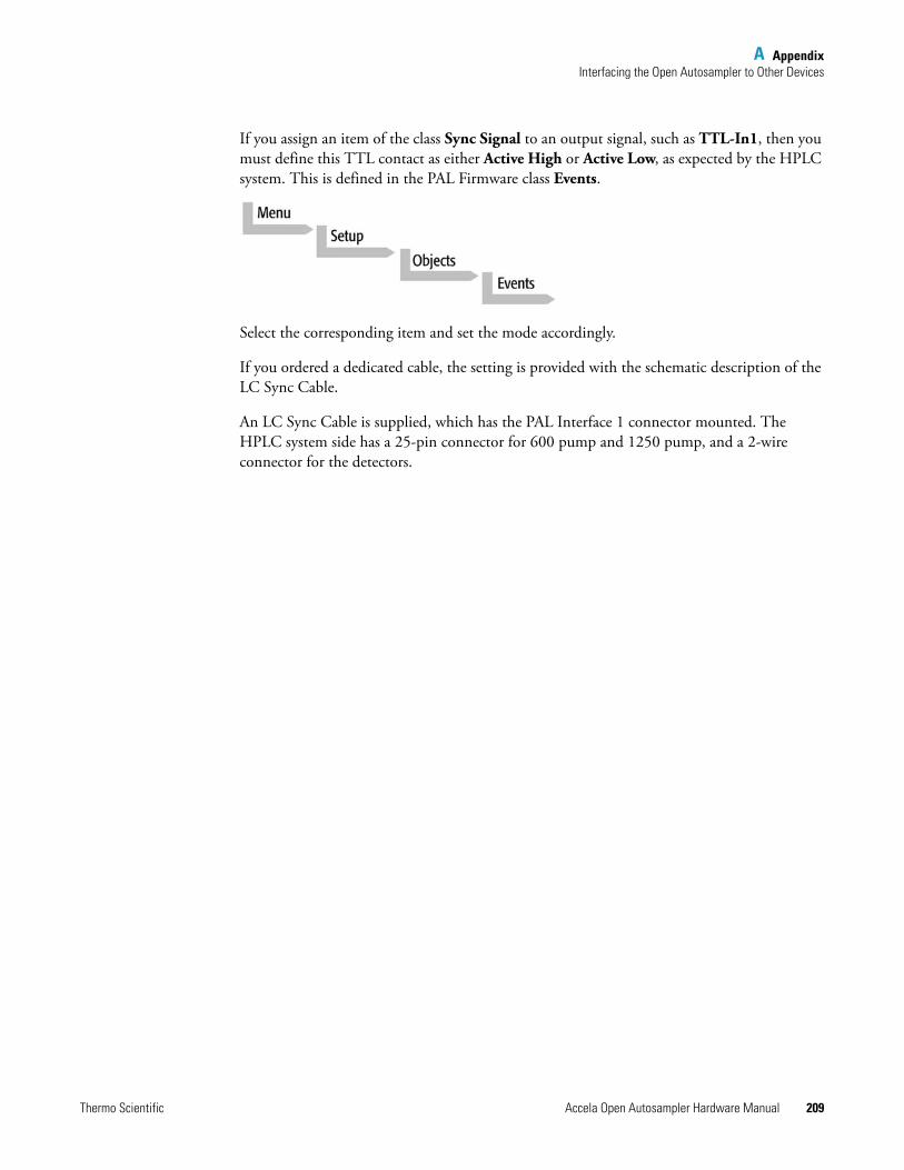
A AppendixInterfacing the Open Autosampler to Other Devices
Thermo Scientific Accela Open Autosampler Hardware Manual 209
If you assign an item of the class Sync Signal to an output signal, such as TTL-In1, then you must define this TTL contact as either Active High or Active Low, as expected by the HPLC system. This is defined in the PAL Firmware class Events.
Select the corresponding item and set the mode accordingly.
If you ordered a dedicated cable, the setting is provided with the schematic description of the LC Sync Cable.
An LC Sync Cable is supplied, which has the PAL Interface 1 connector mounted. The HPLC system side has a 25-pin connector for 600 pump and 1250 pump, and a 2-wire connector for the detectors.

Thermo Scientific Accela Open Autosampler Hardware Manual 211
B
PAL Loader
This chapter describes how to use the PAL Loader sofware version 2.5.0 (or later).
Introduction The purpose of the PAL Loader software is to create a backup file for the complete Accela Open Autosampler firmware. The core software (firmware) and all PAL Firmware Objects, including all settings (Items), local methods, and jobs, are saved as one file.
The PAL Loader software has a second function of loading the firmware or a complete backup file to the Accela Open Autosampler. The PAL Loader application has always been part of the Accela Open Autosampler.
The following PAL Loader software versions are in use:
• PAL Loader version 1.0.1
• PAL Loader version 1.1.1
A new PAL Loader software, version 2.1.0 or later, has been developed for the Accela Open Autosampler.
The Accela Open Autosampler requires PAL Firmware 4.1.x or later, which calls for the new PAL Loader software.
Contents
• Introduction
• New Features of PAL Loader Software 2.1.x
• Installation of PAL Loader Software
• Multiple Shortcuts Assignment
• PAL Loader Software Operation
• Troubleshooting
• Limitations
B PAL LoaderNew Features of PAL Loader Software 2.1.x
212 Accela Open Autosampler Hardware Manual Thermo Scientific
The new PAL Loader software version 2.1.0 (or later) is backwards compatible. The software can be used for all PAL Firmware levels.
The name of the *.exe file has been changed intentionally to avoid conflicts when old and new versions are installed on the same computer:
PAL Loader version 1.1.1: PALLOAD.exe PAL Firmware level up to and including 3.x.x.
PAL Loader version 2.1.x: Setup PALloader.exePAL Firmware level as of 4.1.x or laterbut backwards compatible with lower levels.
New Features of PAL Loader Software 2.1.xThe following features, new since version 1.1.1, are available in the new PAL Loader software:
• The installation software is executable directly from a CD-ROM or any transportable storage device, such as a memory stick.
• The software installation procedure is different from that of Loader version 1.1.1. If they do not already exist, directories are created in the Microsoft™ User Profile.
• The read/write speed for a file is significantly higher. The initial COM Port settings, such as the baud rate, are identical to previous versions. The baud rate is adjusted dynamically during program startup and is displayed on the status line, in the lower right corner of the application window.
• You can create multiple shortcuts and for each one assign a dedicated IP or COM address. This setup facilitates the handling of a number of PAL Systems from a single computer.
Installation of PAL Loader SoftwareThis section contains information about installing the PAL Loader software.
Requirements
PAL Loader software version 2.1.x requires Windows 2000, XP, or Vista™. It does not support lower Windows versions, such as Windows 95, 98, or NT. If installation is necessary in this environment, use PAL Loader version 1.1.1.
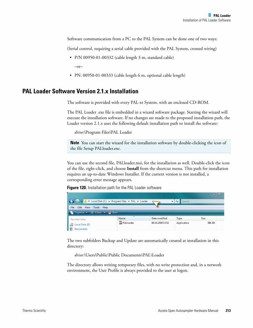
B PAL LoaderInstallation of PAL Loader Software
Thermo Scientific Accela Open Autosampler Hardware Manual 213
Software communication from a PC to the PAL System can be done one of two ways:
(Serial control, requiring a serial cable provided with the PAL System, crossed wiring)
• P/N 00950-01-00332 (cable length 3 m, standard cable)
–or–
• PN: 00950-01-00333 (cable length 6 m, optional cable length)
PAL Loader Software Version 2.1.x Installation
The software is provided with every PAL-xt System, with an enclosed CD-ROM.
The PAL Loader .exe file is embedded in a wizard software package. Starting the wizard will execute the installation software. If no changes are made to the proposed installation path, the Loader version 2.1.x uses the following default installation path to install the software:
drive:\Program Files\PAL Loader
You can use the second file, PALloader.msi, for the installation as well. Double-click the icon of the file, right-click, and choose Install from the shortcut menu. This path for installation requires an up-to-date Windows Installer. If the current version is not installed, a corresponding error message appears.
Figure 120. Installation path for the PAL Loader software
The two subfolders Backup and Update are automatically created at installation in this directory:
drive:\Users\Public\Public Documents\PAL\Loader
The directory allows writing temporary files, with no write protection and, in a network environment, the User Profile is always provided to the user at logon.
Note You can start the wizard for the installation software by double-clicking the icon of the file Setup PALloader.exe.
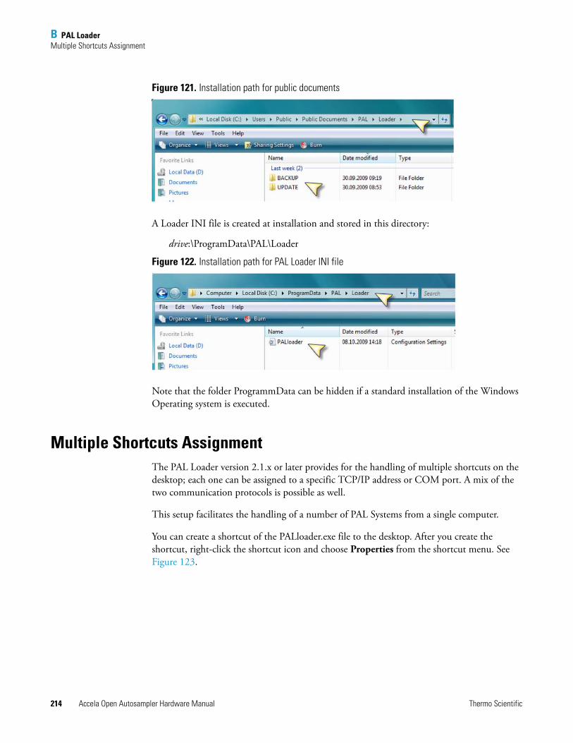
B PAL LoaderMultiple Shortcuts Assignment
214 Accela Open Autosampler Hardware Manual Thermo Scientific
Figure 121. Installation path for public documents
A Loader INI file is created at installation and stored in this directory:
drive:\ProgramData\PAL\Loader
Figure 122. Installation path for PAL Loader INI file
Note that the folder ProgrammData can be hidden if a standard installation of the Windows Operating system is executed.
Multiple Shortcuts AssignmentThe PAL Loader version 2.1.x or later provides for the handling of multiple shortcuts on the desktop; each one can be assigned to a specific TCP/IP address or COM port. A mix of the two communication protocols is possible as well.
This setup facilitates the handling of a number of PAL Systems from a single computer.
You can create a shortcut of the PALloader.exe file to the desktop. After you create the shortcut, right-click the shortcut icon and choose Properties from the shortcut menu. See Figure 123.
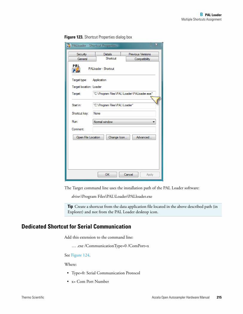
B PAL LoaderMultiple Shortcuts Assignment
Thermo Scientific Accela Open Autosampler Hardware Manual 215
Figure 123. Shortcut Properties dialog box
The Target command line uses the installation path of the PAL Loader software:
drive:\Program Files\PAL\Loader\PALloader.exe
Dedicated Shortcut for Serial Communication
Add this extension to the command line:
… .exe /CommunicationType=0 /ComPort=x
See Figure 124.
Where:
• Type=0: Serial Communication Protocol
• x= Com Port Number
Tip Create a shortcut from the data application file located in the above described path (in Explorer) and not from the PAL Loader desktop icon.
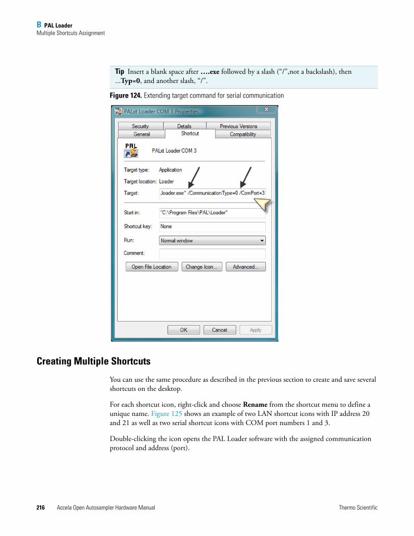
B PAL LoaderMultiple Shortcuts Assignment
216 Accela Open Autosampler Hardware Manual Thermo Scientific
Figure 124. Extending target command for serial communication
Creating Multiple Shortcuts
You can use the same procedure as described in the previous section to create and save several shortcuts on the desktop.
For each shortcut icon, right-click and choose Rename from the shortcut menu to define a unique name. Figure 125 shows an example of two LAN shortcut icons with IP address 20 and 21 as well as two serial shortcut icons with COM port numbers 1 and 3.
Double-clicking the icon opens the PAL Loader software with the assigned communication protocol and address (port).
Tip Insert a blank space after ….exe followed by a slash (“/”,not a backslash), then ...Typ=0, and another slash, “/”.
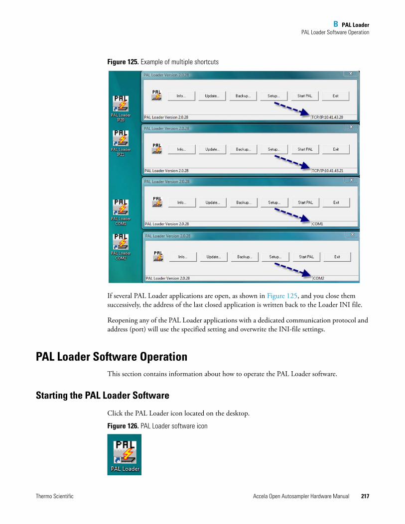
B PAL LoaderPAL Loader Software Operation
Thermo Scientific Accela Open Autosampler Hardware Manual 217
Figure 125. Example of multiple shortcuts
If several PAL Loader applications are open, as shown in Figure 125, and you close them successively, the address of the last closed application is written back to the Loader INI file.
Reopening any of the PAL Loader applications with a dedicated communication protocol and address (port) will use the specified setting and overwrite the INI-file settings.
PAL Loader Software OperationThis section contains information about how to operate the PAL Loader software.
Starting the PAL Loader Software
Click the PAL Loader icon located on the desktop.
Figure 126. PAL Loader software icon
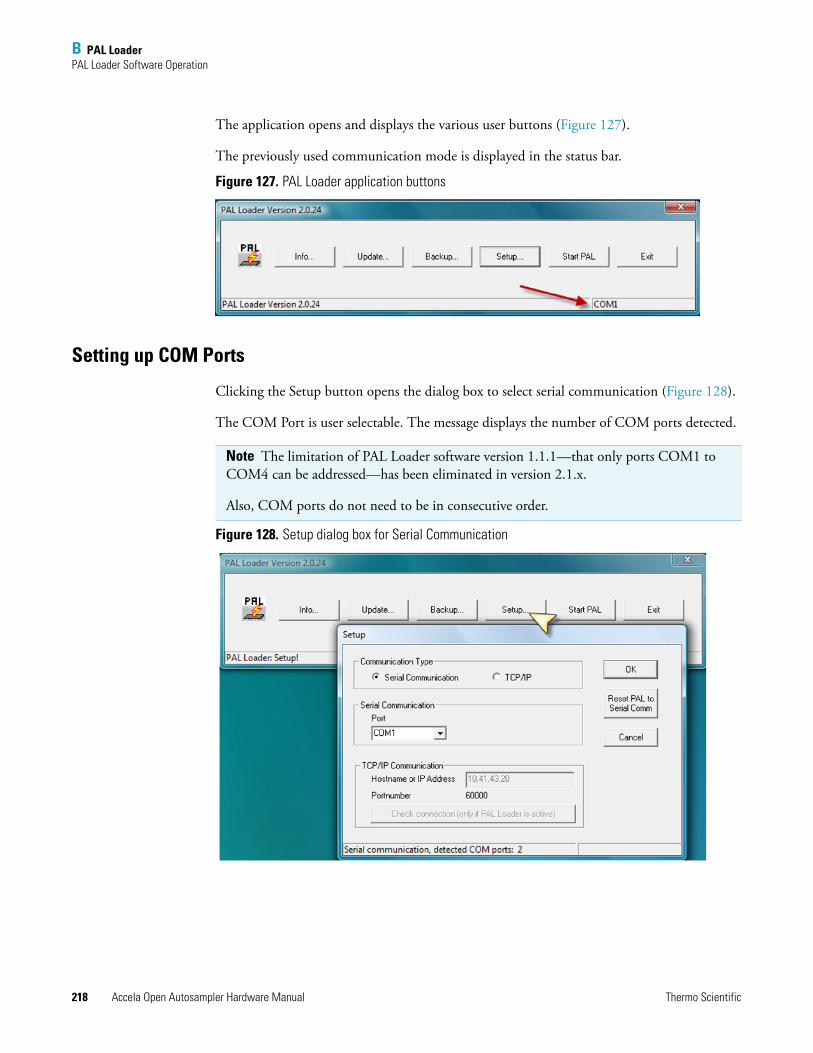
B PAL LoaderPAL Loader Software Operation
218 Accela Open Autosampler Hardware Manual Thermo Scientific
The application opens and displays the various user buttons (Figure 127).
The previously used communication mode is displayed in the status bar.
Figure 127. PAL Loader application buttons
Setting up COM Ports
Clicking the Setup button opens the dialog box to select serial communication (Figure 128).
The COM Port is user selectable. The message displays the number of COM ports detected.
Figure 128. Setup dialog box for Serial Communication
Note The limitation of PAL Loader software version 1.1.1—that only ports COM1 to COM4 can be addressed—has been eliminated in version 2.1.x.
Also, COM ports do not need to be in consecutive order.
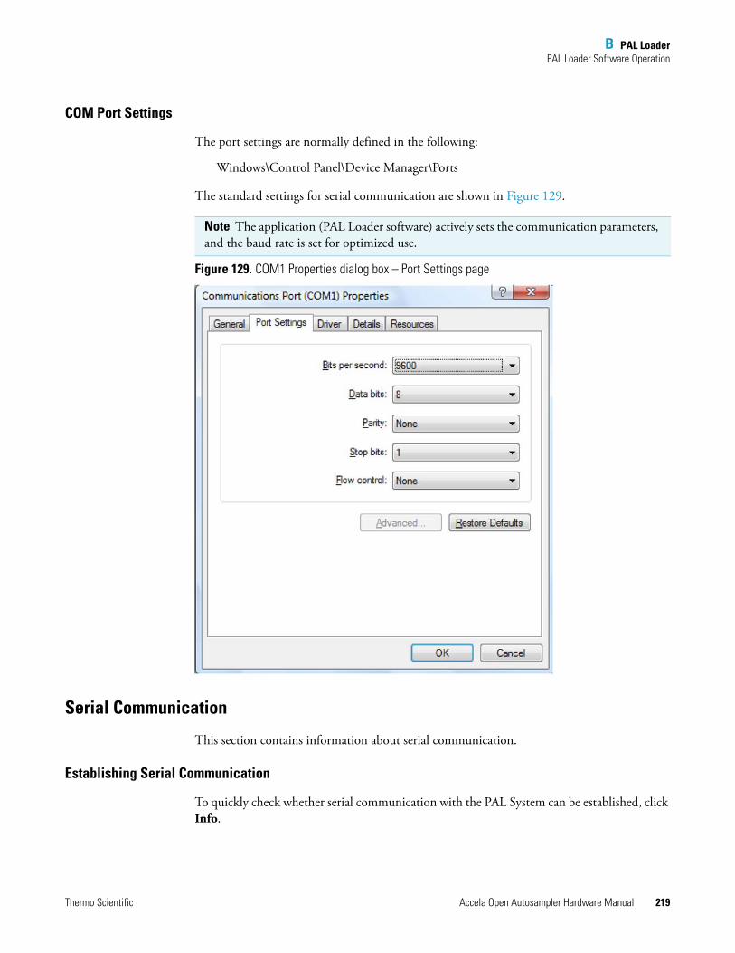
B PAL LoaderPAL Loader Software Operation
Thermo Scientific Accela Open Autosampler Hardware Manual 219
COM Port Settings
The port settings are normally defined in the following:
Windows\Control Panel\Device Manager\Ports
The standard settings for serial communication are shown in Figure 129.
Figure 129. COM1 Properties dialog box – Port Settings page
Serial Communication
This section contains information about serial communication.
Establishing Serial Communication
To quickly check whether serial communication with the PAL System can be established, click Info.
Note The application (PAL Loader software) actively sets the communication parameters, and the baud rate is set for optimized use.
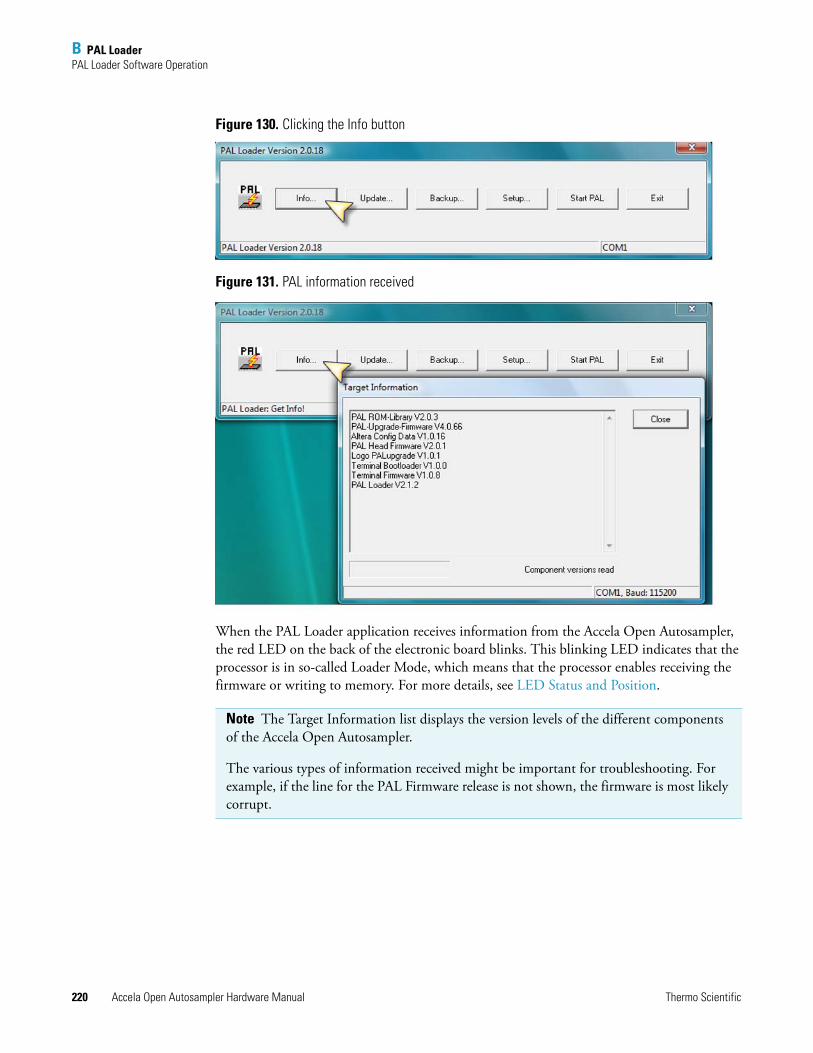
B PAL LoaderPAL Loader Software Operation
220 Accela Open Autosampler Hardware Manual Thermo Scientific
Figure 130. Clicking the Info button
Figure 131. PAL information received
When the PAL Loader application receives information from the Accela Open Autosampler, the red LED on the back of the electronic board blinks. This blinking LED indicates that the processor is in so-called Loader Mode, which means that the processor enables receiving the firmware or writing to memory. For more details, see LED Status and Position.
Note The Target Information list displays the version levels of the different components of the Accela Open Autosampler.
The various types of information received might be important for troubleshooting. For example, if the line for the PAL Firmware release is not shown, the firmware is most likely corrupt.
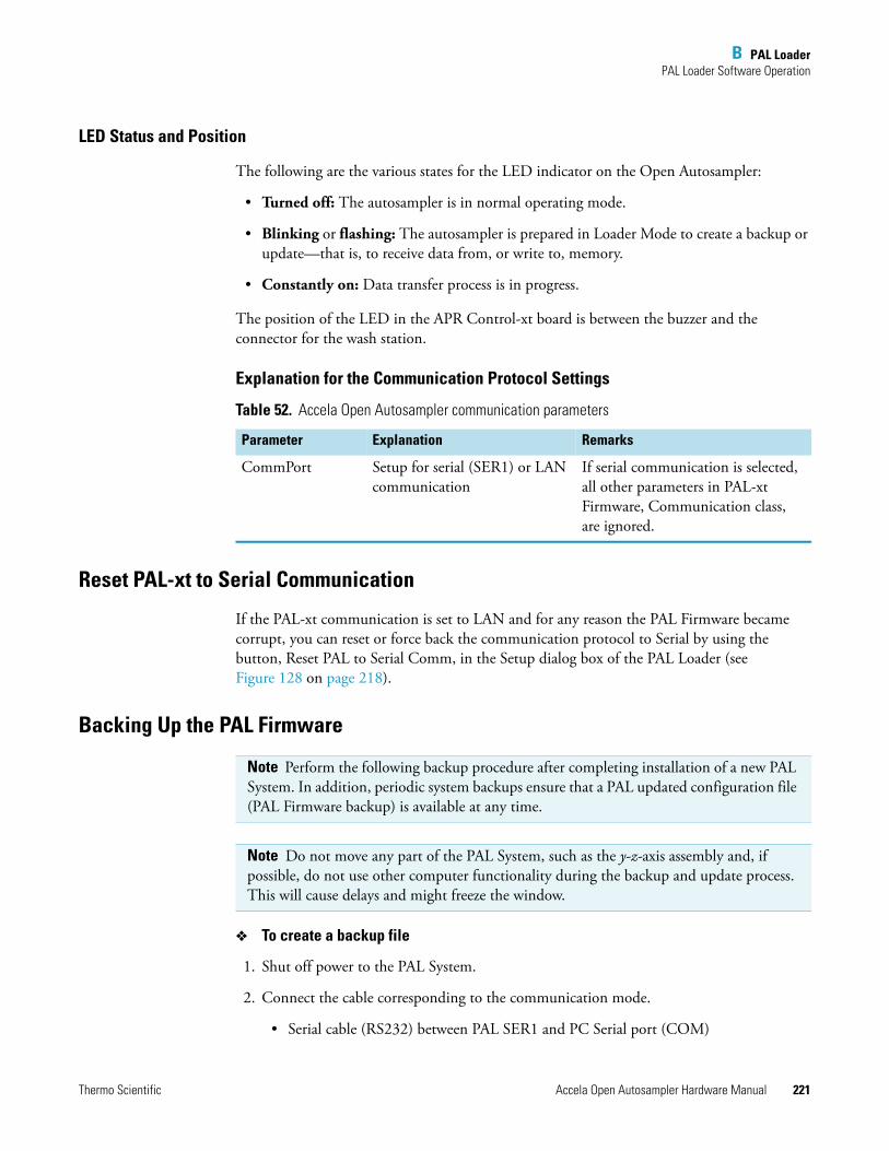
B PAL LoaderPAL Loader Software Operation
Thermo Scientific Accela Open Autosampler Hardware Manual 221
LED Status and Position
The following are the various states for the LED indicator on the Open Autosampler:
• Turned off: The autosampler is in normal operating mode.
• Blinking or flashing: The autosampler is prepared in Loader Mode to create a backup or update—that is, to receive data from, or write to, memory.
• Constantly on: Data transfer process is in progress.
The position of the LED in the APR Control-xt board is between the buzzer and the connector for the wash station.
Explanation for the Communication Protocol Settings
Reset PAL-xt to Serial Communication
If the PAL-xt communication is set to LAN and for any reason the PAL Firmware became corrupt, you can reset or force back the communication protocol to Serial by using the button, Reset PAL to Serial Comm, in the Setup dialog box of the PAL Loader (see Figure 128 on page 218).
Backing Up the PAL Firmware
To create a backup file
1. Shut off power to the PAL System.
2. Connect the cable corresponding to the communication mode.
• Serial cable (RS232) between PAL SER1 and PC Serial port (COM)
Table 52. Accela Open Autosampler communication parameters
Parameter Explanation Remarks
CommPort Setup for serial (SER1) or LAN communication
If serial communication is selected, all other parameters in PAL-xt Firmware, Communication class, are ignored.
Note Perform the following backup procedure after completing installation of a new PAL System. In addition, periodic system backups ensure that a PAL updated configuration file (PAL Firmware backup) is available at any time.
Note Do not move any part of the PAL System, such as the y-z-axis assembly and, if possible, do not use other computer functionality during the backup and update process. This will cause delays and might freeze the window.
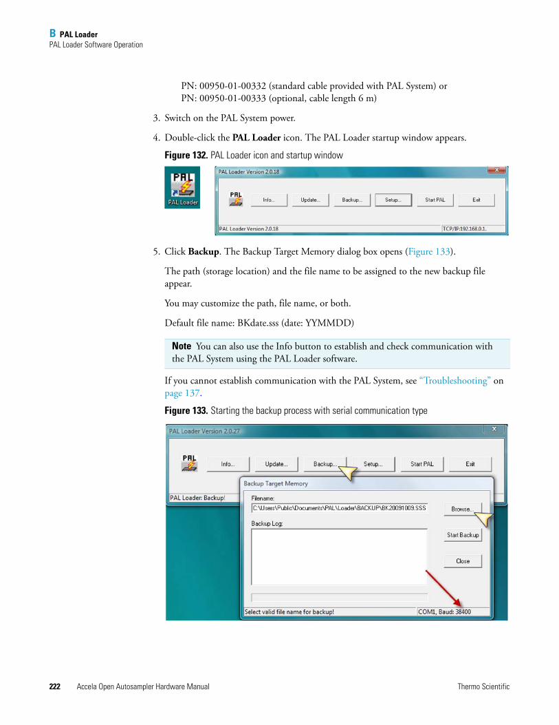
B PAL LoaderPAL Loader Software Operation
222 Accela Open Autosampler Hardware Manual Thermo Scientific
PN: 00950-01-00332 (standard cable provided with PAL System) or PN: 00950-01-00333 (optional, cable length 6 m)
3. Switch on the PAL System power.
4. Double-click the PAL Loader icon. The PAL Loader startup window appears.
Figure 132. PAL Loader icon and startup window
5. Click Backup. The Backup Target Memory dialog box opens (Figure 133).
The path (storage location) and the file name to be assigned to the new backup file appear.
You may customize the path, file name, or both.
Default file name: BKdate.sss (date: YYMMDD)
If you cannot establish communication with the PAL System, see “Troubleshooting” on page 137.
Figure 133. Starting the backup process with serial communication type
Note You can also use the Info button to establish and check communication with the PAL System using the PAL Loader software.
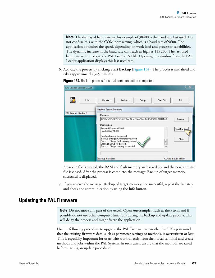
B PAL LoaderPAL Loader Software Operation
Thermo Scientific Accela Open Autosampler Hardware Manual 223
6. Activate the process by clicking Start Backup (Figure 134). The process is initialized and takes approximately 3–5 minutes.
Figure 134. Backup process for serial communication completed
A backup file is created, the RAM and flash memory are backed up, and the newly created file is closed. After the process is complete, the message: Backup of target memory successful is displayed.
7. If you receive the message: Backup of target memory not successful, repeat the last step and check the communication by using the Info button.
Updating the PAL Firmware
Use the following procedure to upgrade the PAL Firmware to another level. Keep in mind that the existing firmware data, such as parameter settings or methods, is overwritten or lost. This is especially important for users who work directly from their local terminal and create methods and jobs within the PAL System. In such cases, ensure that the methods are saved before starting an update procedure.
Note The displayed baud rate in this example of 38400 is the baud rate last used. Do not confuse this with the COM port setting, which is a baud rate of 9600. The application optimizes the speed, depending on work load and processor capabilities. The dynamic increase in the baud rate can reach as high as 115 200. The last used baud rate writes back to the PAL Loader INI file. Opening this window from the PAL Loader application displays this last used rate.
Note Do not move any part of the Accela Open Autosampler, such as the x axis, and if possible do not use other computer functions during the backup and update process. This will delay the process and might freeze the application.
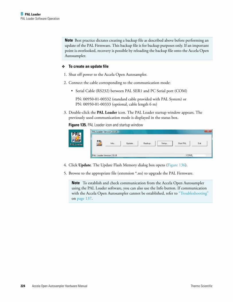
B PAL LoaderPAL Loader Software Operation
224 Accela Open Autosampler Hardware Manual Thermo Scientific
To create an update file
1. Shut off power to the Accela Open Autosampler.
2. Connect the cable corresponding to the communication mode:
• Serial Cable (RS232) between PAL SER1 and PC Serial port (COM)
PN: 00950-01-00332 (standard cable provided with PAL System) or PN: 00950-01-00333 (optional, cable length 6 m)
3. Double-click the PAL Loader icon. The PAL Loader startup window appears. The previously used communication mode is displayed in the status box.
Figure 135. PAL Loader icon and startup window
4. Click Update. The Update Flash Memory dialog box opens (Figure 136).
5. Browse to the appropriate file (extension *.sss) to upgrade the PAL Firmware.
Note Best practice dictates creating a backup file as described above before performing an update of the PAL Firmware. This backup file is for backup purposes only. If an important point is overlooked, recovery is possible by reloading the backup file onto the Accela Open Autosampler.
Note To establish and check communication from the Accela Open Autosampler using the PAL Loader software, you can also use the Info button. If communication with the Accela Open Autosampler cannot be established, refer to “Troubleshooting” on page 137.
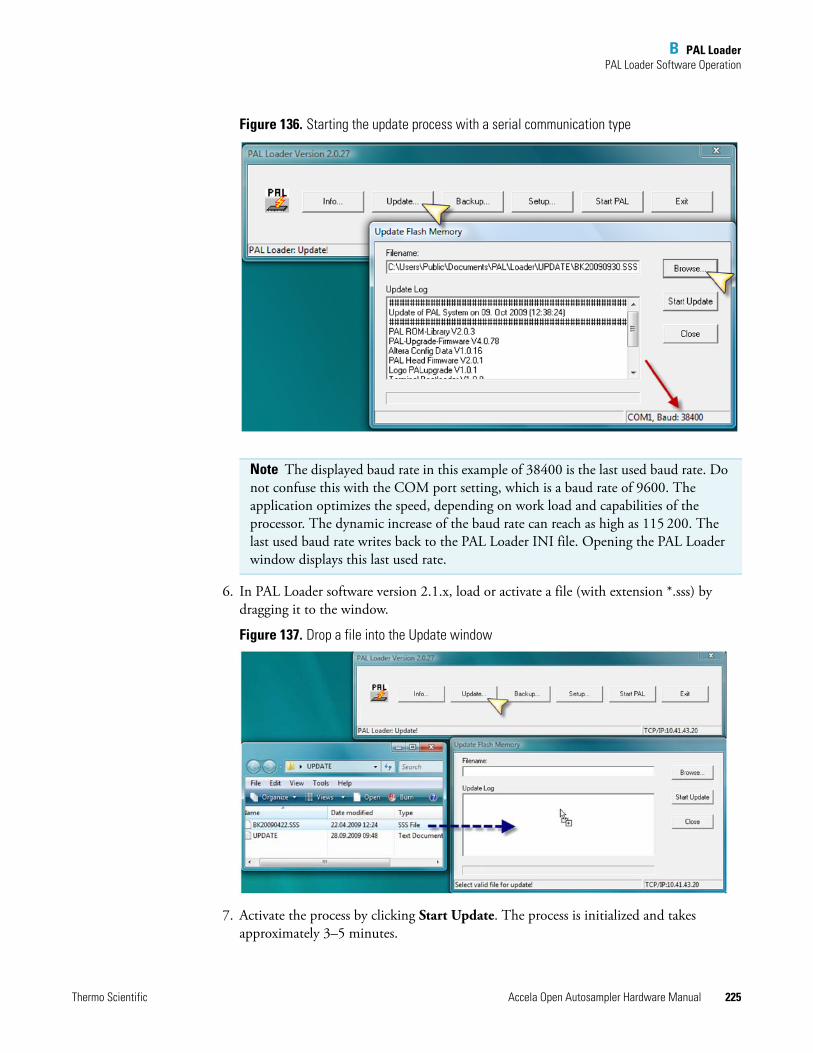
B PAL LoaderPAL Loader Software Operation
Thermo Scientific Accela Open Autosampler Hardware Manual 225
Figure 136. Starting the update process with a serial communication type
6. In PAL Loader software version 2.1.x, load or activate a file (with extension *.sss) by dragging it to the window.
Figure 137. Drop a file into the Update window
7. Activate the process by clicking Start Update. The process is initialized and takes approximately 3–5 minutes.
Note The displayed baud rate in this example of 38400 is the last used baud rate. Do not confuse this with the COM port setting, which is a baud rate of 9600. The application optimizes the speed, depending on work load and capabilities of the processor. The dynamic increase of the baud rate can reach as high as 115 200. The last used baud rate writes back to the PAL Loader INI file. Opening the PAL Loader window displays this last used rate.
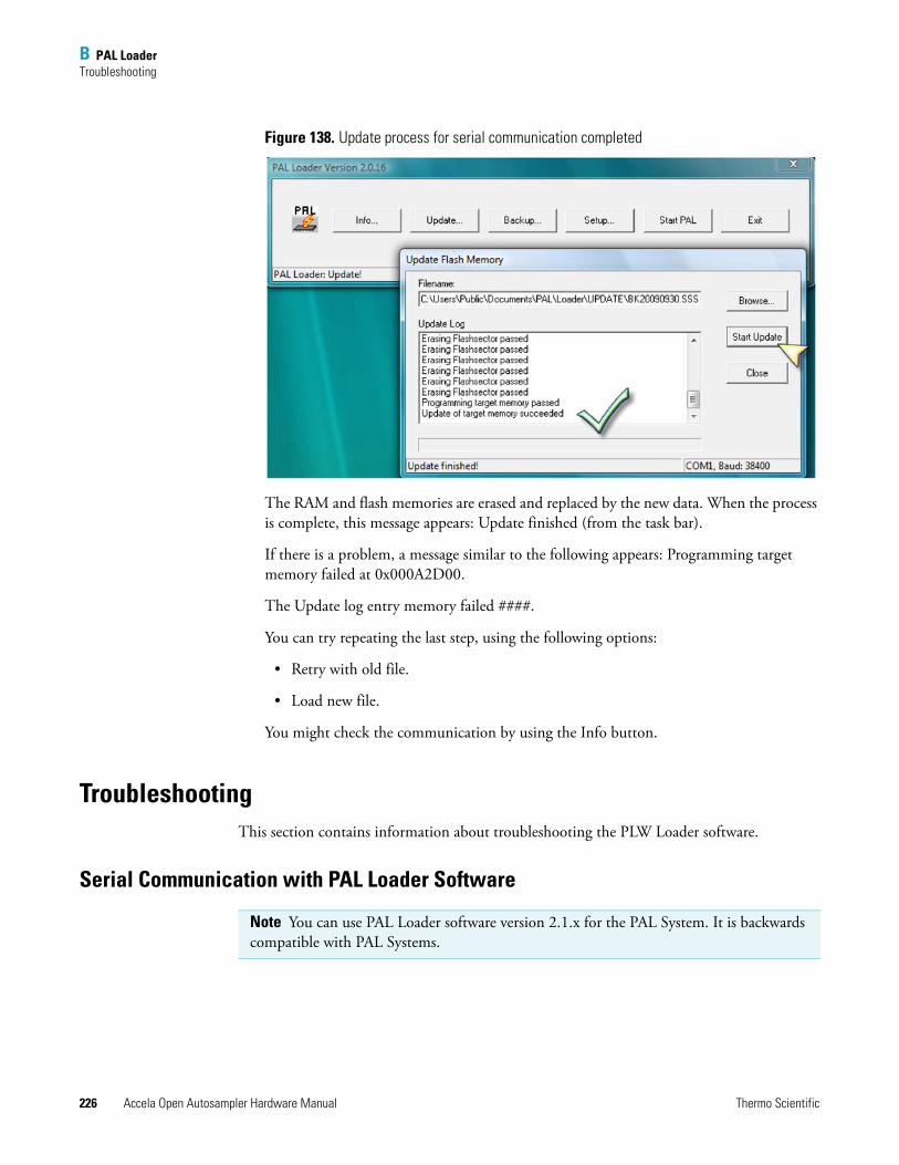
B PAL LoaderTroubleshooting
226 Accela Open Autosampler Hardware Manual Thermo Scientific
Figure 138. Update process for serial communication completed
The RAM and flash memories are erased and replaced by the new data. When the process is complete, this message appears: Update finished (from the task bar).
If there is a problem, a message similar to the following appears: Programming target memory failed at 0x000A2D00.
The Update log entry memory failed ####.
You can try repeating the last step, using the following options:
• Retry with old file.
• Load new file.
You might check the communication by using the Info button.
TroubleshootingThis section contains information about troubleshooting the PLW Loader software.
Serial Communication with PAL Loader Software
Note You can use PAL Loader software version 2.1.x for the PAL System. It is backwards compatible with PAL Systems.
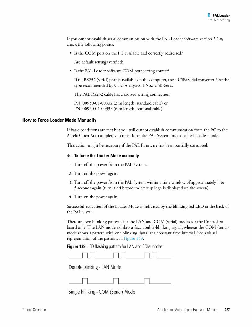
B PAL LoaderTroubleshooting
Thermo Scientific Accela Open Autosampler Hardware Manual 227
If you cannot establish serial communication with the PAL Loader software version 2.1.x, check the following points:
• Is the COM port on the PC available and correctly addressed?
Are default settings verified?
• Is the PAL Loader software COM port setting correct?
If no RS232 (serial) port is available on the computer, use a USB/Serial converter. Use the type recommended by CTC Analytics: PNo.: USB-Ser2.
The PAL RS232 cable has a crossed wiring connection.
PN: 00950-01-00332 (3 m length, standard cable) or PN: 00950-01-00333 (6 m length, optional cable)
How to Force Loader Mode Manually
If basic conditions are met but you still cannot establish communication from the PC to the Accela Open Autosampler, you must force the PAL System into so-called Loader mode.
This action might be necessary if the PAL Firmware has been partially corrupted.
To force the Loader Mode manually
1. Turn off the power from the PAL System.
2. Turn on the power again.
3. Turn off the power from the PAL System within a time window of approximately 3 to 5 seconds again (turn it off before the startup logo is displayed on the screen).
4. Turn on the power again.
Successful activation of the Loader Mode is indicated by the blinking red LED at the back of the PAL x axis.
There are two blinking patterns for the LAN and COM (serial) modes for the Control–xt board only. The LAN mode exhibits a fast, double-blinking signal, whereas the COM (serial) mode shows a pattern with one blinking signal at a constant time interval. See a visual representation of the patterns in Figure 139.
Figure 139. LED flashing pattern for LAN and COM modes
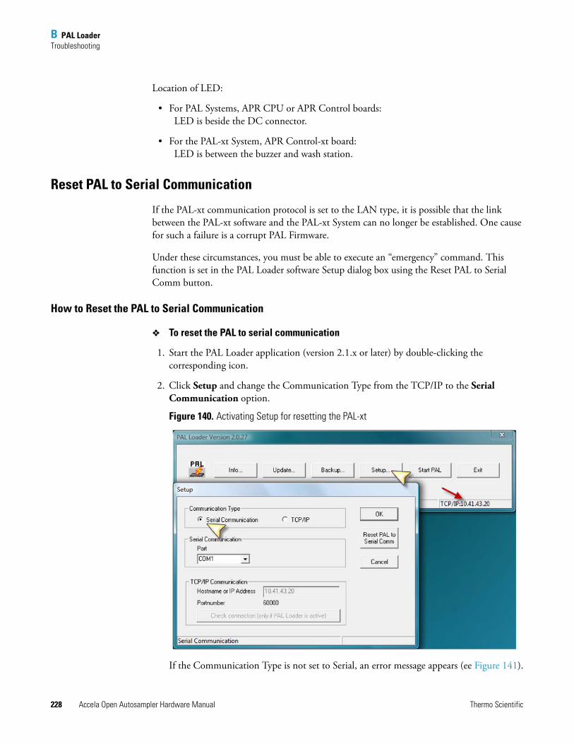
B PAL LoaderTroubleshooting
228 Accela Open Autosampler Hardware Manual Thermo Scientific
Location of LED:
• For PAL Systems, APR CPU or APR Control boards: LED is beside the DC connector.
• For the PAL-xt System, APR Control-xt board: LED is between the buzzer and wash station.
Reset PAL to Serial Communication
If the PAL-xt communication protocol is set to the LAN type, it is possible that the link between the PAL-xt software and the PAL-xt System can no longer be established. One cause for such a failure is a corrupt PAL Firmware.
Under these circumstances, you must be able to execute an “emergency” command. This function is set in the PAL Loader software Setup dialog box using the Reset PAL to Serial Comm button.
How to Reset the PAL to Serial Communication
To reset the PAL to serial communication
1. Start the PAL Loader application (version 2.1.x or later) by double-clicking the corresponding icon.
2. Click Setup and change the Communication Type from the TCP/IP to the Serial Communication option.
Figure 140. Activating Setup for resetting the PAL-xt
If the Communication Type is not set to Serial, an error message appears (ee Figure 141).
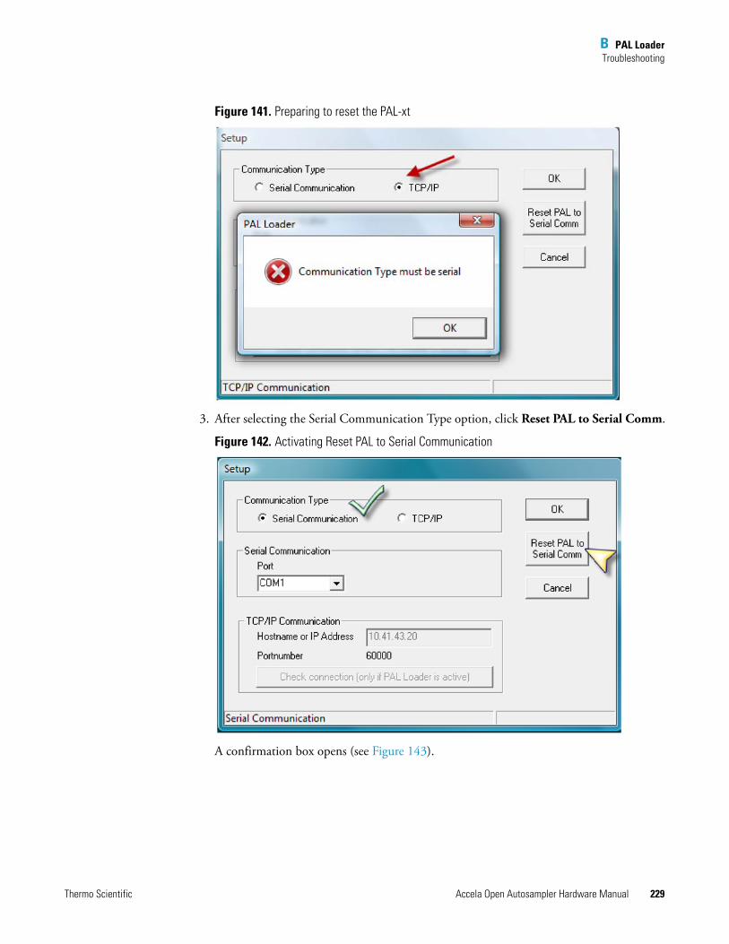
B PAL LoaderTroubleshooting
Thermo Scientific Accela Open Autosampler Hardware Manual 229
Figure 141. Preparing to reset the PAL-xt
3. After selecting the Serial Communication Type option, click Reset PAL to Serial Comm.
Figure 142. Activating Reset PAL to Serial Communication
A confirmation box opens (see Figure 143).
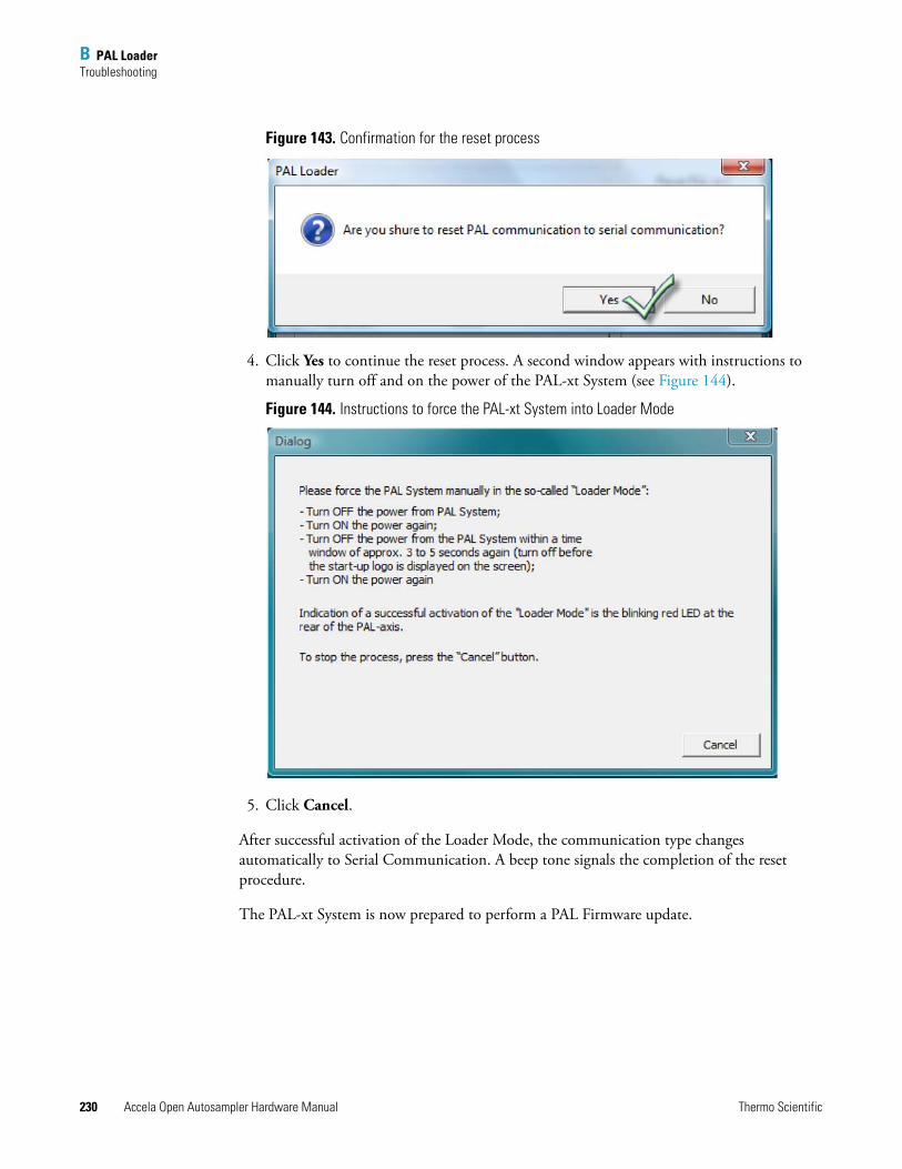
B PAL LoaderTroubleshooting
230 Accela Open Autosampler Hardware Manual Thermo Scientific
Figure 143. Confirmation for the reset process
4. Click Yes to continue the reset process. A second window appears with instructions to manually turn off and on the power of the PAL-xt System (see Figure 144).
Figure 144. Instructions to force the PAL-xt System into Loader Mode
5. Click Cancel.
After successful activation of the Loader Mode, the communication type changes automatically to Serial Communication. A beep tone signals the completion of the reset procedure.
The PAL-xt System is now prepared to perform a PAL Firmware update.
B PAL LoaderTroubleshooting
Thermo Scientific Accela Open Autosampler Hardware Manual 231
Erratic Behavior of Software or Flash Memory
In some rare cases the red LED might continue to blink after a PAL Firmware update. You cannot start the PAL System from the PAL Loader Start PAL button or by powering it off/on. If such a case occurs, take the following steps:
1. Power down and wait at least 30 seconds before the unit is powered up again. If the PAL System is not restored, go to the next step.
2. Reload a complete PAL Firmware backup file. A complete backup file means core software including all PAL Firmware Objects data, content of RAM, and flash memory.
If this action is still unsuccessful, go to the next step.
3. Power down the unit again and remove the board (APR CPU, APR Control, or APR Control -xt). Before you handle an individual board, be careful of static charge.
4. Connect the DC cable, the spiral cable for the terminal, and either the Serial or Ethernet cable to the board on-the-fly.
5. Start the software UPDATE process again.
6. If none of these actions is successful, change the board.
Any severe error requiring changing the board typically means that the Loader section of the flash memory can no longer be addressed, which results in communication failure.
7. Charge the battery overnight (36 V), and reload a complete PAL Firmware backup file (core software and PAL Firmware Objects).
Failure to Complete BACKUP or UPDATE Process
Avoid touching the PAL System during the read or write processes (BACKUP or UPDATE). Do not move, for example, the y-, z-axis assembly during a process. This will delay its completion and could result in an error message and stopping the process completely.
Furthermore, the window can freeze (shown in a frozen progress bar). This might also happen if the computer processor is very busy with other tasks at the same time. Try to avoid using any other computer function during the process.
Note A PCB, APR CPU, APR Control, or APR Control-xt , which has not been connected to current for a period of six months or longer, can result in a low battery level. Because a low battery will no longer support the RAM memory, data loss is likely.
B PAL LoaderLimitations
232 Accela Open Autosampler Hardware Manual Thermo Scientific
LimitationsKnown limitations to consider for troubleshooting purposes relate to the Windows operating system. The PAL Loader software version 2.1.x is compatible with the following systems only:
• XP Professional (Service Pack 2)
• Vista Enterprise (Service Pack 1)
• Windows 7 beta build 7000, preliminary tests fulfilled
Thermo Scientific Accela Open Autosampler Hardware Manual 233
C
Installing and Using the PAL Object Manager Software
Read this chapter to install, set up, and use the PAL Object Manager software. This chapter is intended for frequent Accela Open Autosampler users or new users who are experienced at configuring and using automated systems to run existing analytical methods. Before using the PAL Object Manager, make sure you have properly installed and set up the Accela Open Autosampler using the instructions in “Installing the Accela Open Autosampler” on page 11.
When you add a new hardware module to the Accela Open Autosampler, use the PAL Object Manager software to load new PAL firmware objects onto the system to support those modules. The Object Manager mode also helps create and maintain object lists from an existing Accela Open Autosampler.
After adding an object to the Accela Open Autosampler, choose Restart Pal from the File menu to start the system so other software applications can use the object.
The latest PAL Object Manager software is backwards compatible. You can use the software with all PAL firmware levels.
Contents
• Installing PAL Object Manager
• Getting Started with PAL Object Manager
IMPORTANT Before using the PAL Object Manager software to make changes to your system, back up the current system definition using the PAL Loader software. If problems occur while using the PAL Object Manager software, repair the system using PAL Loader to restore the back up configuration file. See “PAL Loader” on page 211.
Because this software can change your system to the point that the autosampler and Thermo PAL does not function properly, make changes to objects only if you are an advanced user and understand how the changes you make can impair system functioning.
Thermo Fisher has defined the hardware and software configuration for your autosampler. Changes to this configuration can impact system functioning.
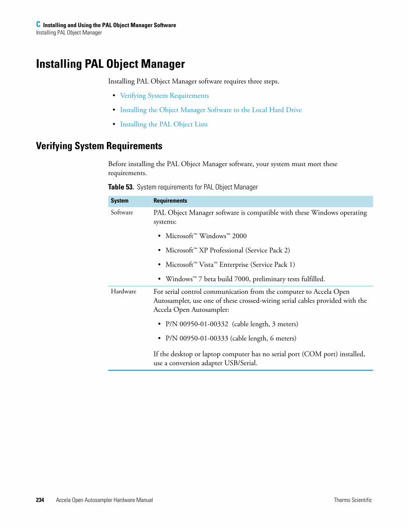
C Installing and Using the PAL Object Manager SoftwareInstalling PAL Object Manager
234 Accela Open Autosampler Hardware Manual Thermo Scientific
Installing PAL Object Manager Installing PAL Object Manager software requires three steps.
• Verifying System Requirements
• Installing the Object Manager Software to the Local Hard Drive
• Installing the PAL Object Lists
Verifying System Requirements
Before installing the PAL Object Manager software, your system must meet these requirements.
Table 53. System requirements for PAL Object Manager
System Requirements
Software PAL Object Manager software is compatible with these Windows operating systems:
• Microsoft™ Windows™ 2000
• Microsoft™ XP Professional (Service Pack 2)
• Microsoft™ Vista™ Enterprise (Service Pack 1)
• Windows™ 7 beta build 7000, preliminary tests fulfilled.
Hardware For serial control communication from the computer to Accela Open Autosampler, use one of these crossed-wiring serial cables provided with the Accela Open Autosampler:
• P/N 00950-01-00332 (cable length, 3 meters)
• P/N 00950-01-00333 (cable length, 6 meters)
If the desktop or laptop computer has no serial port (COM port) installed, use a conversion adapter USB/Serial.
C Installing and Using the PAL Object Manager SoftwareInstalling PAL Object Manager
Thermo Scientific Accela Open Autosampler Hardware Manual 235
Installing the Object Manager Software to the Local Hard Drive
The PAL firmware objects are grouped in various folders that must be linked to the Object Manager software. To avoid any conflicts with the link, load the software to your local hard drive before copying the object folders.
You must have administrative rights to install the software.
To install the Object Manager software to the local hard drive
1. Put the Object Manager CD in your computer.
2. To start the installation, double-click the PAL Object Manager setup.exe file.
The installation wizard begins installing the software.
3. If there is no change to the proposed installation path, install the software to the default location:
C:\Program Files\PAL\Object Manager
Installing the PAL Object Lists
After installing the Object Manager software, install the PAL Object Lists folder. This folder contains all PAL firmware object lists in alphabetical order by class, for example, syringes, trays, and wash stations.
Install the PAL object lists folder in the same directory as the PAL Object Manager software.
To install the PAL Object Lists folder
1. Find the Pal Object Lists folder on the CD.
2. Copy the folder and paste it into the same folder on your hard drive where the PAL Object Manager resides. The default location is C:\Program Files\PAL\Object Manager.
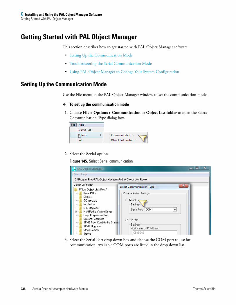
C Installing and Using the PAL Object Manager SoftwareGetting Started with PAL Object Manager
236 Accela Open Autosampler Hardware Manual Thermo Scientific
Getting Started with PAL Object ManagerThis section describes how to get started with PAL Object Manager software.
• Setting Up the Communication Mode
• Troubleshooting the Serial Communication Mode
• Using PAL Object Manager to Change Your System Configuration
Setting Up the Communication Mode
Use the File menu in the PAL Object Manager window to set the communication mode.
To set up the communication mode
1. Choose File > Options > Communication or Object List folder to open the Select Communication Type dialog box.
2. Select the Serial option.
Figure 145. Select Serial communication
3. Select the Serial Port drop down box and choose the COM port to use for communication. Available COM ports are listed in the drop down list.
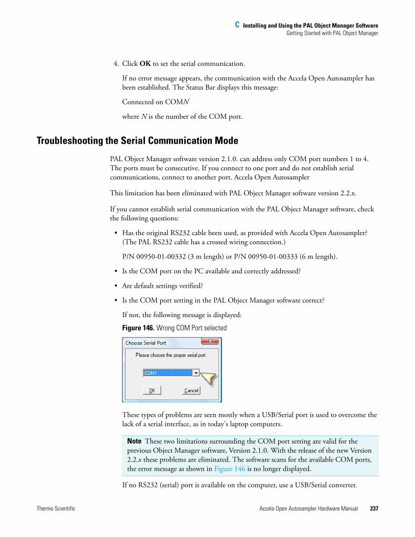
C Installing and Using the PAL Object Manager SoftwareGetting Started with PAL Object Manager
Thermo Scientific Accela Open Autosampler Hardware Manual 237
4. Click OK to set the serial communication.
If no error message appears, the communication with the Accela Open Autosampler has been established. The Status Bar displays this message:
Connected on COMN
where N is the number of the COM port.
Troubleshooting the Serial Communication Mode
PAL Object Manager software version 2.1.0. can address only COM port numbers 1 to 4. The ports must be consecutive. If you connect to one port and do not establish serial communications, connect to another port. Accela Open Autosampler
This limitation has been eliminated with PAL Object Manager software version 2.2.x.
If you cannot establish serial communication with the PAL Object Manager software, check the following questions:
• Has the original RS232 cable been used, as provided with Accela Open Autosampler? (The PAL RS232 cable has a crossed wiring connection.)
P/N 00950-01-00332 (3 m length) or P/N 00950-01-00333 (6 m length).
• Is the COM port on the PC available and correctly addressed?
• Are default settings verified?
• Is the COM port setting in the PAL Object Manager software correct?
If not, the following message is displayed:
Figure 146. Wrong COM Port selected
These types of problems are seen mostly when a USB/Serial port is used to overcome the lack of a serial interface, as in today's laptop computers.
If no RS232 (serial) port is available on the computer, use a USB/Serial converter.
Note These two limitations surrounding the COM port setting are valid for the previous Object Manager software, Version 2.1.0. With the release of the new Version 2.2.x these problems are eliminated. The software scans for the available COM ports, the error message as shown in Figure 146 is no longer displayed.
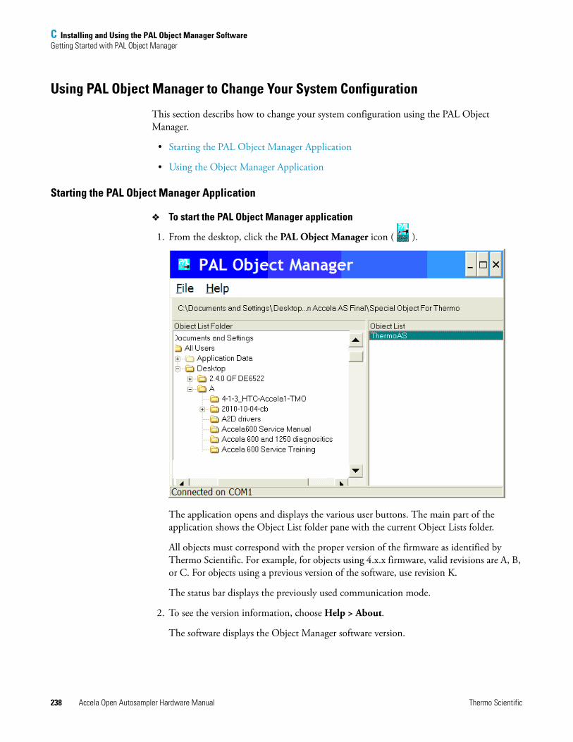
C Installing and Using the PAL Object Manager SoftwareGetting Started with PAL Object Manager
238 Accela Open Autosampler Hardware Manual Thermo Scientific
Using PAL Object Manager to Change Your System Configuration
This section describs how to change your system configuration using the PAL Object Manager.
• Starting the PAL Object Manager Application
• Using the Object Manager Application
Starting the PAL Object Manager Application
To start the PAL Object Manager application
1. From the desktop, click the PAL Object Manager icon ( ).
The application opens and displays the various user buttons. The main part of the application shows the Object List folder pane with the current Object Lists folder.
All objects must correspond with the proper version of the firmware as identified by Thermo Scientific. For example, for objects using 4.x.x firmware, valid revisions are A, B, or C. For objects using a previous version of the software, use revision K.
The status bar displays the previously used communication mode.
2. To see the version information, choose Help > About.
The software displays the Object Manager software version.
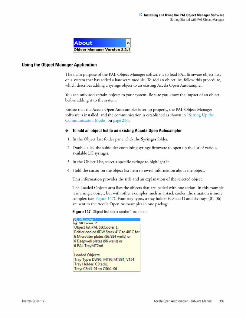
C Installing and Using the PAL Object Manager SoftwareGetting Started with PAL Object Manager
Thermo Scientific Accela Open Autosampler Hardware Manual 239
Using the Object Manager Application
The main purpose of the PAL Object Manager software is to load PAL firmware object lists on a system that has added a hardware module. To add an object list, follow this procedure, which describes adding a syringe object to an existing Accela Open Autosampler.
You can only add certain objects to your system. Be sure you know the impact of an object before adding it to the system.
Ensure that the Accela Open Autosampler is set up properly, the PAL Object Manager software is installed, and the communication is established as shown in “Setting Up the Communication Mode” on page 236.
To add an object list to an existing Accela Open Autosampler
1. In the Object List folder pane, click the Syringes folder.
2. Double-click the subfolder containing syringe firmware to open up the list of various available LC syringes.
3. In the Object List, select a specific syringe to highlight it.
4. Hold the cursor on the object list item to reveal information about the object.
This information provides the title and an explanation of the selected object.
The Loaded Objects area lists the objects that are loaded with one action. In this example it is a single object, but with other examples, such as a stack cooler, the situation is more complex (see Figure 147). Four tray types, a tray holder (CStack1) and six trays (01-06) are sent to the Accela Open Autosampler in one package.
Figure 147. Object list stack cooler 1 example
C Installing and Using the PAL Object Manager SoftwareGetting Started with PAL Object Manager
240 Accela Open Autosampler Hardware Manual Thermo Scientific
Review the information to make sure that the correct object list has been selected and to understand what is included in this list. For example, you need to know whether all necessary tray types for the application are included or if you must specifically select another type and send it to the Accela Open Autosampler as a second task.
5. Click Send to Accela Open Autosampler to read the Accela Open Autosampler configuration and send the selected objects to the Accela Open Autosampler.
The configuration file is temporarily stored in the computer memory.
After the file has been sent successfully to the Accela Open Autosampler, the message “xx objects received” is displayed in the status bar, providing feedback from the Accela Open Autosamplerto the Object Manager application.
In the example using the LC syringe, 25 μL, the Object Manager software might send two objects in a single file. In this case, the first object contains the geometric definition of the syringe itself and the second object specifies which plunger motor driver is assigned to this particular syringe.
The same concept is used to send the desired objects to the Accela Open Autosampler for all other object lists.
The Object Manager always lists the object being sent in the last line of the PAL firmware class, visible from the local terminal. The Object Manager software can quickly check whether the PAL firmware has received the new object.
In some cases—seen in particular in the PAL but not in the PAL-xt System—you might receive an error message: Memory full. To resolve this problem, you must delete as many objects as possible from the Accela Open Autosampler that you are not using. You can link a syringe to a method and a job. First delete the job, then the method, and finally the syringe object. See “To delete objects” on page 240 for information about deleting objects.
Confirm your understanding of the Object List parameters and descriptions to make sure that the correct, desired objects are sent to the PAL firmware. In certain cases where complexity is greater—for example, multi-position valve drives—the guideline provides the correct order of steps in the process to provide reliable functioning of the Accela Open Autosampler.
To delete objects
1. Use the Accela Open Autosampler handheld device to delete objects.
In the handheld device, objects are displayed as a tree. Identify the object and delete it according to instructions in “Operating the Accela Open Autosampler” on page 65.
To delete multi-object items, delete the lowest items first and then remove higher objects until you delete the top-level object.
Thermo Scientific Accela Open Autosampler Hardware Manual 241
I
Symbols 235
AAccela Open Autosampler
adapter cable for detector 42assembling 14components 1electrical connections 35error messages 137external connectors 200firmware overview 191installing 11interconnect cable 39maintenance 165naming convention 171object positions 49operating 65operating and environmental requirements 9physical specifications 8replacement parts 153sound pressure level 9specifications 6system limitations 206unpacking components 11using control terminal 65
Bbacking up PAL firmware, PAL Loader 221
Ccables
Accela Open Autosampler system interconnect cable 39Accela Pump adapter cable 46detector adapter cable 42
communication modesetting up for PAL Object Manager software 236
complianceFCC iii
regulatory iiiWEEE v
control terminalfunction keys 67illustration 66menu screens 66using 65
Cycle 169cycle composer macros 85cycle composer macros or ICC cycles, installing 85Cycle Editor 85
DDLW
Actuator/Solenoid 28characterizing features 3cycle 96cycle for fast injection 118cycle for standard injection 96fast injection cycle 91Flow Diverter 12functionality 94Holding Loop 12–13macro definitions 85manifold 28needle guide length tool 12–13operating 93overview 3Plunger Holder 12–13Pump Module 12–13replacement 153spare parts ordering information 155standard injection cycle 88Syringe 12, 29Syringe Holder assembly 12–13Syringe Needle 12–13Tubing Kit 12–13
DLW Actuator/Solenoid 94DLW pump module, replacing 154DLW Pumps 94
Index
242 Accela Open Autosampler Hardware Manual Thermo Scientific
Index: E
DLW replacing partssyringe 154syringe holder assembly 154wash station 154
DLW Syringe Holder Assembly, installing 28DLW Wash Station
Injection Valve plumbing and connection 34installing 26
DLW-2spare parts ordering information 159
DLW-2, components 13DLW-2, definition 4Dynamic Load and Wash (DLW) 3
Eelectromagnetic compatibility ivEMC compliance iiiExtended User Mode, accessing 172external connectors, Accela Open Autosampler 200
FFast Wash Station for two different solvents 2FCC compliance iiifirmware
error codes 194overview 191
flow path, injection valve 60
IICC cycles 85info functions 78
free objects/free items 80hardware 79maintenance 79software 79
Injection Unit 2installing 18ribbon cable 20
injection unit 11injection valve
flow path 60Valco W-Type 6-Port 62
installing the PAL Object Manager software 235introduction, Object Manager Application 239
JJob 169Job queue 169job queue 69
building and starting 70cancelling 71
Kkeypad terminal 2, 11keypad terminal, installing 22
LLC injection valve, installing 23logfile 78
MMethod 170Method parameters 170methods 67
creating 67deleting 69editing and viewing 68
Module 170MSQ Plus MS detector
Accela Open Autosampler system interconnect cable connection 40, 43
OObject class 170Object Item 170Object list 170Object Manager 170object positions, descriptions 51Objects 170Open Autosampler components 1ordering information, DLW spare parts 155ordering information, DLW-2 spare parts 159
PPAL Firmware, updating 223PAL Loader 211
backing up PAL Firmware 221dedicated shortcut for serial communication 215installing 212multiple shortcuts assignment 214new features 212operating 217reset PAL-xt to serial communication 221serial communication 219setting up COM ports 218starting 217
PAL Object Lists folderinstalling for PAL Object Manager software 235
Thermo Scientific Accela Open Autosampler Hardware Manual 243
Index: R
PAL Object Manager Software 239PAL Object Manager software
backing up your system configuration 233port settings
choose COM port for PAL Object Manager software 236troubleshooting for PAL Object Manager software 237
power supply, installing 23pump holder, mounting 24pumps, self-priming 3
Rreference points
injection valve 57Wash Station 55waste 56
regulatory compliance iiiresetting PAL-xt to serial communication, PAL Loader 221
Ssafety guard 2, 11safety standards iiiself-priming micro pumps 3serial communication, PAL Loader 219setting up COM parts, PAL Loader 218setting up LAN communication, PAL Loader 221setup functions
objects 82selecting 80sounds 81time 81
solvent lines, priming 93Stack 171Stack Cooler
condensation build-up 134temperature alarm 133temperature control 132temperature setting 131temperature stability 133
stand-alone supports 11standard chromatographic tests 148standard liquid syringe holders 28standard stand-alone supports 2starting, PAL Object Manager Application 238syringe kit 2, 11system components, Accela Open Autosampler 2system requirements
PAL Object Manager software 234
TThermo PAL driver for Xcalibur 85Torx driver 20Tray 171tray 2
holder 52position 52rows and columns 53
Tray holder 171Tray Type
pattern explanation 185Tray type 171troubleshooting
Accela Open Autosampler 137PAL Loader 226special considerations 142
Uupdating PAL firware, PAL Loader 223utility functions 71
dilutors 76injector 74syringe 72tools 77tray 73vial 76wash station 75
VValve Needle Guide Assembly, installing 34valve penetration value, defining 58
WWash Station assembly 11Wash Station reference point 55WEEE compliance v
Xx-, y-axes assembly 2
Zz-axis 2