Embed Size (px)
Citation preview

ACC Controller
Owner’s Manual
Installation, Programming, and Operating Instructions
September 2006
ACC Owner’s Manual Rev E - 9/06 1 of 60

ACC Owner’s Manual Introduction The ACC controller, in its many modular configurations, is Hunter’s premium industrial-grade controller for high-performance irrigation control. Its primary purpose is to operate 24VAC irrigation solenoids or low-draw solid state relays for specific durations at specific times. It can also be connected to various sensors, providing automatic shutdown and notification in case of emergencies, and actual flow records and responses in real time. With plug-in Com and other modules, the ACC can also communicate with a computerized central control system via hardwired cable, radio, dial-up telephone, or cellular modem. ACC is also prewired to accept Hunter wireless remote controls.
• This product should not be used for anything other than what is described in this Document.
• This product should only be serviced by trained and authorized personnel. • This product is designed for continuous outdoor use above sea level to 15,000
feet/4.5km at temperatures 0-50°C. • These units have an IPX4 rating.
ACC Owner’s Manual Rev E - 9/06 2 of 60

Introduction ...................................................................................................................................................2 Controller Interface & Key Components .......................................................................................................4 Wiring Compartment Interior .........................................................................................................................6 Explanation of Symbols.................................................................................................................................7 Installation .....................................................................................................................................................7 Metal Cabinet, Wall Mount Installation..........................................................................................................7 Connecting AC Main Power, Wall mount cabinet .........................................................................................8 Metal Cabinet, optional Pedestal Installation ................................................................................................9 Connecting the Metal Pedestal Main AC Power.........................................................................................10 Plastic Pedestal Installation ........................................................................................................................10 Connecting Plastic Pedestal AC Main Power .............................................................................................11 Connecting Earth Ground ...........................................................................................................................13 Installing Station Modules ...........................................................................................................................13 Connecting the valve wires .........................................................................................................................16 Connecting Decoder Output Path wires......................................................................................................17 Decoder Programming ................................................................................................................................17 24 VAC Test Terminal (constant 24V): .......................................................................................................18 Connecting the Master Valve(s) and/or Pump Start Relay(s).....................................................................19 Connecting a Rain or Freeze shut off device (optional & not included)......................................................19 Connecting the Hunter Flow Sensor (optional & not included) ...................................................................20 ICR Remote Control....................................................................................................................................21 Quick Start...................................................................................................................................................23 Controller Programming and Operation ......................................................................................................25 Using the Information button.......................................................................................................................25 Setting current Date and Time ....................................................................................................................25 Setting Program Start Times.......................................................................................................................26 Setting Program Start Times.......................................................................................................................26 Setting Station Run Time Duration .............................................................................................................27 Setting Station watering duration ................................................................................................................27 Changing Seasonal Adjust..........................................................................................................................28 Setting Days to Water .................................................................................................................................28 Setting Pump and Master Valve Operation.................................................................................................30 Setting Pump and Master Valve Operation.................................................................................................30 Setting Station Cycle and Soak durations...................................................................................................30 Setting Station Cycle and Soak durations...................................................................................................30 Setting Flow Monitoring...............................................................................................................................31 Flow Alarms ................................................................................................................................................34
Alarm Logs (also see Historical Data/Data History section).................................................... 35 Tips on Flow Alarms: ............................................................................................................... 35
Setting Clik™ Sensor Operation .................................................................................................................36 Sensor Alarms.............................................................................................................................................37 Setting Program Overlap Options ...............................................................................................................38
Option One: Stack or Overlap................................................................................................... 38 Option Two: Smartstack™ ........................................................................................................ 39 Option Three: SSG/Smartstack................................................................................................. 39
Setting Station & Program Names ..............................................................................................................40 Historical Data/Data History ........................................................................................................................41
Common Fault Messages.......................................................................................................... 42 Hidden Features..........................................................................................................................................43
No Water Window (INFORMATION+Set Program Start Time) ............................................ 43 Delay between Stations INFORMATION+Set Station Run Times ......................................... 44 Making the M/V circuit normally open (INFORMATION+Set Pump Operation).................. 44 Setting the Flow Sensor size and type (INFORMATION+Set Flow Monitoring)................... 45 SSG (Simultaneous Station Group) setup (INFORMATION+Overlap) .................................. 46
ACC Owner’s Manual Rev E - 9/06 3 of 60

Custom Manual program setup (INFORMATION + Manual Operation)................................ 48 To start a Custom Manual:..........................................................................................................................49
Test Program: Programs button (hold) ..................................................................................... 49 Easy Retrieve™ backup (INFORMATION + Programs button at Run position) .................... 50
Manual Operations......................................................................................................................................51 System Off...................................................................................................................................................52 Reset ...........................................................................................................................................................53 Decoder Operations (ACC99D versions)....................................................................................................53
Connecting the 2-wire paths ..................................................................................................... 53 Status Lights (ADM-99 Output Module).................................................................................. 54 Decoder Programming .............................................................................................................. 54 Decoder Pump/Master Valves .................................................................................................. 57
Troubleshooting ..........................................................................................................................................58 Specifications ..............................................................................................................................................59
Dimensions ............................................................................................................................... 59 Electrical ................................................................................................................................... 59
Controller Interface & Key Components
A. LCD Display – Backlit, adjustable contrast display (re-lights when any button is pressed). B. + Button – Increases flashing value, depending on function. C. – Button - Decreases flashing value. Most items in ACC screens “wrap” so that you can continue in either direction through all the choices.
A
B C D E F
G H
I
J
K
L
MN
D. Copy/Learn Button – Copies a time or value in a flashing field, for pasting into similar fields. Also used to Learn typical flow (when a flow sensor has been installed). E. Paste/Pause Button – Pastes a copied time or value into a new field. Also used as Pause/Resume feature during watering, shuts off devices for 30 mins. or until Resumed. F. Programs Button – Selects one of the automatic Programs (A-F), starts Test program, allows Reset (with Reset button). G. Up and Down Arrow Buttons –
ACC Owner’s Manual Rev E - 9/06 4 of 60

Used to move up and down through adjustable functions in various screens, and to select higher or lower numbered items. H. Left and Right Buttons – Used to move left and right in some screens. I. Information Button – Lights display, and provides instant Help and other information, depending on dial position. Also used to access Hidden Features, when held down while turning to specific dial positions. J. Programming Dial – Used to access all functions of ACC. The most basic automatic watering can be set up in the first 4 dial positions. K. Reset Button – recessed switch erases some or all memory when combined with pressing specific buttons. L. Facepack Release Button – Hold down while removing facepack from inner door panel. M. Door Grip – convenient finger grip for opening inner door. N. Logo Badge – removable, for installation of optional communications modules.
ACC Owner’s Manual Rev E - 9/06 5 of 60
Wiring Compartment Interior
A. Inner Door – opens to main wiring compartment.
A B C D E
F
G
HI JK
L
B. AC Wiring compartment – for connection of 120/230V AC power with 1 x .75”/19mm conduit opening.
C. Fuse – 2 Amp (fast) 250V, 6 x 20mm. D. Conduit openings, low voltage - (2 x 2.5”/64mm, 2 x .75”/19mm) E. Wire tie holders for valve wires (valve wiring area) F. Station output terminals (valve wires) – screw terminals on 6-station output modules. G. Upper deck panel with LED status indicators – numbered station lights, green for
active, red for faults. H. Sliding lock for output modules – permits addition or removal of output modules, locks
wired modules in place. I. Master Module – includes sensor, Pump/Master Valve, and other accessory connections. J. Communications module area (cover removed) – removable panel covers installation
compartment for Com modules and radio. K. SmartPort – Integrated connector for ICR/SRR receiver (on side of cabinet). L. Earth Ground Lug – for connection of earth ground copper wire (for surge protection
only). Do not connect valve commons – see Master Module for Common wiring of solenoids and valves.
ACC Owner’s Manual Rev E - 9/06 6 of 60
Explanation of Symbols = AC
= Consult Documentation = Hazardous Voltages Present = Double Insulated Installation (Trained Personnel Only) Metal Cabinet, Wall Mount Installation Tools required:
• Long drill bit and extension • Philips screwdriver or bit (for use with long extension) – magnetic recommended. • Wire strippers
Location Requirement: a) a switch or circuit-breaker shall be included in building installations; b) the switch or breaker shall be in close proximity to the controller, and within easy reach of the operator; c) the switch or breaker shall be marked as the disconnecting device for the controller. Avoid direct exposure to sprinkler spray. Shaded or partially shaded areas are preferable to prolonged direct sunlight.
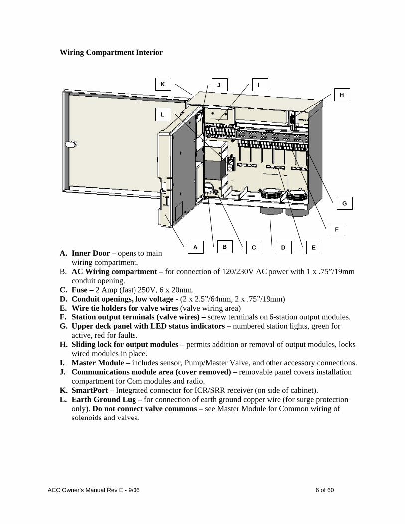
Facepack Door
The ACC controller is relatively heavy, about 30lbs/13.6 kg in tmetal wall mount configuration. Mounting includes a posihanger to assist with installation.
he tioning
reely.
efore mounting, it is easier to remove the metal cabinet door.
be
Positioning Hanger
Mounting hardware has been included, but it is the installer’s responsibility to insure that adequate hardware is used for the physical location. ACC is approximately 15.5”/40cm wide. Allow another 15.5”/40cm to the left of the controller for the door to open f BSwing the door open, grasp the top securely, and push up on thebottom of the door, near the lower hinge. The hinges should disengage and the metal door canremoved.
Mounting Holes
ACC Owner’s Manual Rev E - 9/06 7 of 60

Remove the facepack assembly from the controller. • Open the facepack door using the recess on the right. • Disconnect the gray ribbon cable from the back of the facepack. Pull gently on the
ribbon cable… a slight rocking motion may help disengage the connector. • Push up on the upper door hinge, and tilt the door so that it disengages the hinge posts.
Remove the facepack and set aside in a safe location. OPTIONAL: Locate the positioning hanger in the upper center of the controller’s location on the wall, leaving adequate clearance for the opened door to the left.
• Drill a pilot hole for the anchor and insert. • Install one #10/5mm screw in this hanger position, leaving approximately ¼”(6-7mm) out
of the anchor to allow the controller to hang from this screw. • Hang the controller from the keyhole slot in the positioning hanger. • Place a level on the top of the controller cabinet and level. • Locate the 3 mounting holes in the cabinet. These are visible from the front, with the
facepack removed, in deep recesses in the top two corners, and another shallow recess in the bottom center.
• Mark each of these 3 locations and install anchors. • Reposition controller on the hanger and use a long screwdriver or drill extension
(3”/75mm) with magnetic tip to install the remaining 3 screws, one at each anchor position, and secure.
Connecting AC Main Power, Wall mount cabinet The ACC can operate with either 120VAC or 230VAC power, depending on how the incoming AC wires are connected. Supply wires must be 14AWG (1.85mm) or larger. The ACC is prewired for 120V operation but can easily be changed to 230V. Consult or hire a licensed electrician for these connections as required.
• Turn AC power off at the source, and verify that it is off. • Remove the wiring compartment screws and the wiring compartment door. • Strip approximately ½” (13mm) of insulation from the end of each of the AC power wires,
and route into the wiring compartment through the conduit. • Locate the white plastic terminal block, and wire according to the following diagrams.
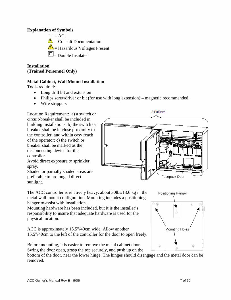
For 120V~ operation, connect the incoming black power wire (hot) to align in the wiring block with the black wire lead from the transformer. Insert the incoming black wire lead into the hole opposite the black transformer wire and tighten screw securely. Connect the incoming neutral (white) wire to align with the blue lead from the transformer.
ACC Owner’s Manual Rev E - 9/06 8 of 60
The 120V~ ground wire (bare, or green) is not used in ACC transformer connections. The service ground wire may be connected to earth ground if required. Tighten screw and replace cover.
For 230V~ operation, connect the incoming power wire (hot, brown in many wiring standards) to align in the wiring block with the brown wire lead from the transformer. Connect the incoming Neutral (blue in some international standards) wire to align with the blue lead from the transformer. Tighten screws and replace cover.
Apply AC~ power and test. Refer to Earth Ground and Station Wiring sections for additional connections. Metal Cabinet, optional Pedestal Installation Location Requirement: a) a switch or circuit-breaker shall be included in building installations; b) the switch or breaker shall be in close proximity to the controller, and within easy reach of the operator; c) the switch or breaker shall be marked as the disconnecting device for the controller.
• Installing the pedestal 1. Assemble the mounting template using the instructions provided with the pedestal.
ACC Owner’s Manual Rev E - 9/06 9 of 60

2. Using the enclosed mounting template, locate the bolts two inches deep in the concrete pad, in the locations indicated. The pad can be any size but at least a two-foot square is recommended. 3. Level the mounting bolts before the concrete sets. 4. After the concrete sets, remove the door of the pedestal and slide the pedestal down onto the four bolts. Secure the pedestal to the bolts using the enclosed washers and nuts. 5. Remove the door and faceplate of the ACC and attach the metal cabinet of the ACC to the top of the pedestal using the ½”/13mm and 2”/50mm metal conduit nuts in the pedestal. Tighten securely by engaging teeth with a screwdriver and tapping in a clockwise direction. Connecting the Metal Pedestal Main AC Power
Conduit nuts
6. Connect AC power wiring as in the metal wall cabinet. Route the AC power wiring through the metal pedestal and up into the ACC wiring compartment. Follow the AC wiring instructions for the metal wall cabinet closely. 7. Replace the pedestal door first and then replace the faceplate and the cabinet door. The pedestal door cannot be removed or replaced when the cabinet door is closed. Refer to Earth Ground and Station Wiring sections for additional connections. Plastic Pedestal Installation Select a location for installation of the controller based upon these factors: 1. Availability of 120/230VAC~ power. 2. Do not locate under overhanging branches of trees or any structure that may attract lightning. 3. Avoid locations where sprinklers supward onto the controller, and low arsubject to flooding.
pray eas
nd
4. Locate controller in a location that is central to all valves/sprinklers that it controls to maintain visible operation areduce wire lengths/costs. Concrete Base Installation: 1. Set forms for a 21" (533 mm) wide x 26" (660 mm) long concrete base. The base pad should be 2" (50 mm) above grade for proper drainage. 2. Position a 11⁄2" to 3" (38 to 76 mm) diameter conduit sweep elbow for the field wires (size will vary depending upon the number of valve wires entering the controller), a 1" (25 mm) conduit sweep elbow for the power supply, and a 1" conduit sweep elbow for any communication wires, if applicable. Secure the sweeps so they will enter the bottom of the controller correctly. 3. Allow approximately 3" of conduit above the surface of the concrete pad. 4. Shape the concrete base to shed any water away from the controller.
ACC Owner’s Manual Rev E - 9/06 10 of 60

5. Prepare the template for insertion in the concrete. Twist one nut on each of the four J-bolts to the bottom of the thread and slide each bolt through the hole in the template. Put a washer and nut on each J-bolt to secure it to the template (allow a minimum of 21⁄2" of thread protruding above each nut). 6. Work the J-bolts down into the concrete until the template sits level on top of the concrete. Smooth and allow the concrete to cure (at least 24 hours). Note: It is important with plastic pedestals to ensure a smooth mounting surface. Uneven surfaces may cause the pedestal to distort, preventing proper sealing of the doors. 7. Remove the nuts and washers from the concrete base. Place the pedestal over the bolts and secure with nuts and washers. Note: Remove both doors and lift the pedestal from the main body. Two people are required for this task. Connecting Plastic Pedestal AC Main Power ACC Plastic Pedestal wiring is somewhat different than wall mount wiring. Read carefully. Verify that AC power is off before proceeding. Insert the two 120/230~ power wires through the AC power conduit (keep power wires separate from low voltage and communication wires) and route into the wiring compartment. The ACC pedestal has a separate wiring junction box below the main transformer assembly. All 120/230~ connections are made in this junction box. Do not remove the cover immediately below the transformer with the fuse holder. The ACC pedestal junction box is equipped with an external power switch, which is connected in the AC wiring path. Remove the screws for the junction box cover, and open carefully to the right. The switch wires remain attached through the wiring process. Locate the two terminal blocks, upper and lower, inside the junction box. Incoming AC power connections are made at the lower of the two terminal blocks. Choosing 120V~ or 230V~ power is performed at the upper of the two terminal blocks. 120VAC (120~) Installation: At the lower terminal block, connect the incoming power wire (black) to align with the brown wire leading to the switch. 120/230~
Switch
Lower Terminal
Block
Upper Terminal
Block
Junction Box
Brown Wire from Switch
ACC Owner’s Manual Rev E - 9/06 11 of 60

Insert stripped wire and tighten screw. Connect the neutral incoming power wire (white) to align with the blue wire in the lower terminal block and tighten. The upper terminal block determines the operating voltage, depending on where the brown wire from the switch is connected. For 120V~ operation, connect the brown wire from the switch to align with the Black wire in the upper terminal block. Insert stripped wire and tighten screw securely. Replace cover, apply AC power, and test. Refer to Earth Ground and Station Wiring sections for additional connections. 230VAC (230~) Installation: At the lower terminal block, connect the incoming power wire (often brown) to align with the brown wire leading to the switch. Insert stripped wire and tighten screw. Connect the neutral incoming power wire (often blue) to align with the blue wire in the lower terminal block and tighten. The upper terminal block determines the operating voltage, depending on where the brown wire from the switch is connected. On the upper terminal block, connect the brown wire from the switch to the screw aligned with the Brown wire in the upper terminal block. Insert the stripped wire and tighten screw securely. Replace cover, apply AC power, and test. Refer to Earth Ground and Station Wiring sections for additional connections.
ACC Owner’s Manual Rev E - 9/06 12 of 60

Connecting Earth Ground (all configurations) The ACC features a copper earth ground lug, to the immediate right of the transformer assembly. This earth ground connection is isolated from the primary AC power and is used to ground incoming surges from the communications and output valve wires. This connection can be used to ground the primary AC power. Do NOT connect any portion of the 120/230V~ input power to this point. With the controller power Off, loosen the slotted screw in the center of the ground lug. Route a bare 6 AWG (4.11mm dia. or greater) earth ground wire into the wiring area through the .75” (19mm) conduit opening directly beneath the ground lug, in the bottom of the controller cabinet. Do not route the ground wire through the same conduit as the incoming primary AC power! Loosen the ground lug screw, insert the ground wire into the ground lug and tighten the screw to secure the ground wire. Do not overtighten.
Ground Wire in .5”/13mm
conduit
Ground LugGrounding hardware should be selected according to standards established by American Society of Irrigation Consultants Earth Grounding guideline 100-2002 (available at their website, www.asic.org). Acceptable grounding consists of an 8’ (2.5m) copper-clad rod or stake, or a 4” x 96” (100mm x 240cm) copper plate, or both, placed in the earth at least 8’(2.5m) away from the controller, and with the ground wire at right angles to the communications and valve wires, if possible. Ideal grounding resistance would be 10 Ohms or less as measured with a “megger” or similar device. Please consult the ASIC reference for more detailed considerations of this critical step. Improper connection to earth ground voids the effectiveness of the output module surge protection. Installing Station Modules ACC expands in 6-station increments with intelligent output modules, requiring no tools to install and only a screwdriver for station wiring connections. The base configuration is 12 stations (two 6-station modules installed) with a maximum station capacity in a metal wall cabinet of 42 stations (7 total output modules x 6 stations, each). ACC can be expanded at any time with either of the following types of modules:
ACC Owner’s Manual Rev E 9/06 13 of 60

1. ACM600, 6-station output module with surge suppression and diagnostic LEDs. 2. AGM600, 6-station output module with heavy-duty surge suppression and diagnostic
LEDs.
These two types of modules may be mixed within the same installation, if desired.
ACC Owner’s Manual Rev E 9/06 14 of 60

Output Modules (ACM600, AGM600)
AGM600 6-station output module with
Heavy Duty Surge Protection
ACM600 6-station output module
A
B
E
D
C
A. Station Output Screw Terminals – Connect no more than two solenoids each. B. Station Status LEDs – Green for station activity, Red for fault or short. C. Locking lugs (for module lock) D. Gold plated electrical contacts (lower rear of module) E. Additional surge components, AGM versions (visible through module)
There is also an optional decoder output module (ADM99) which installs in the first 3 expansion slots. The decoder configuration is 99 stations, maximum.
Upper Deck cover
• To install expansion modules, turn the dial to the
Run position. • Open the inner facepack door, and locate the m
lock. Slide the module lock to the “Unlockposition.
odule ed”
traight
• Flip up the upper deck cover. Slide the modules up, into the next available position, viewed from left to right… do not skip slots by leaving them empty.
• Install a module by aligning it firmly in the lower portion of the next available slot, and sliding sup until it clicks into place. One of the LEDs will illuminate red briefly, to show that the new module has been recognized.
Slide ADM99 in first 3 slots
ACC Owner’s Manual Rev E 9/06 15 of 60

• Tthe silver contact on the back of the controller cabinet must engage a mating slot in the back of the expansion module. Do not “tip” or force the module into place. Slide straight up, from the bottom of the slot.
ADM99 Decoder Output Module
• While at the Run dial position, press the Information button. The current station size will be shown, and should include any new modules you have added.
• Decoder output modules may NOT be mixed with the “conventional” ACM/AGM-600 output modules.
• Decoder output modules are always installed in the first three slots. Connecting the valve wires Each station output module has 6 screw terminals for connection of individual station wires. The terminals will accept from 22 AWG (.64mm dia.) to 12 AWG (2.05mm dia.) wires. Each station output is rated for .56 A, max, or enough to operate two typical Hunter solenoids simultaneously. Once the output module is installed in the slot, the station numbers assigned to the output module appear in the upper deck label above each slot.
• The modules may be removed, if necessary, without
disconnecting the field wiring. However, they must be reinserted into exactly the same slot, or the station addresses will be switched.
Master Module
COM terminals
• Connect the return wires from the valves to one of the 3 terminals on the Master Module marked COM. Since many valve solenoid wires will need to connect to these 3 common terminals,
• Route valve wires between control valve location and controller.
• At valves, attach a common wire to either solenoid wire of all valves. This is most commonly a white colored wire. Attach a separate control wire to the remaining wire of each valve. All wire splice connections should be done using waterproof connectors.
• Open hinged faceplate on the controller to access the terminal area.
• Route valve wires through the conduit and attach conduit to the controller at the large conduit openings on the right side of the bottom of the cabinet.
• Strip 1⁄2" (13 mm) of insulation from ends of all wires. Secure valve common wire to COM (Common) terminals on the Master Module. Then attach all individual valve control wires to appropriate station terminals.
ACC Owner’s Manual Rev E 9/06 16 of 60
Connecting Decoder Output Path wires
Up to 99 stations may be operated over a single pair of wires (known as a “path”) using decoders. The decoder output module allows up to 6 two-wire paths to the field decoders. The maximum number of decoder stations is still 99, but multiple paths allow the shortest wire runs. You may use any number of paths to reach all 99 stations. Each path should consist of Hunter Industries Model IDWIRE1 or IDWIRE2 color-coded decoder wire. This is a twisted, solid-core wire suitable for direct burial, and is always color-coded red and blue. All red/blue connections in the two-wire path must be made with DBR6 waterproof connectors or equal. Each path has a red and a blue terminal with its number on the decoder output module.
• Route decoder path wires through the conduit into the wiring compartment. Leave adequate slack in the wires for thermal contraction.
• Strip 1⁄2" (13 mm) of insulation from the red and blue ends. • Connect the red wire to the red “1” terminal, and the blue wire from the same pair to the
blue “1”. Repeat for any other paths as needed. It is not necessary to connect the paths in a loop, back to any other point in the controller. Simply insert decoders in the path until complete, and stop at the last decoder on the path.
• Do not connect a wire path from one controller to another controller! Decoder Programming When a decoder output module is installed, the controller facepack will recognize it and the station size will change to “99” (regardless of how many stations are in use). This will also unlock the normally hidden Decoder displays in the following dial positions. Advanced Features: Main decoder/station programming will be activated. This is the primary decoder programming position. Set Pump Operation: Will allow decoder stations to be designated as Pump/Master valves. The controller never has more than 2 P/M outputs, but it is possible to assign one or both of them to a decoder output (instead of the terminal on the Master Module). See complete decoder setup information in the Decoder Operations section of this manual.
ACC Owner’s Manual Rev E 9/06 17 of 60

Master Module: Key Connections
A
A
AH
G
E F C
B
D
A. Common Ground Terminals (x 3) – for return wires (often white) from stations and
master valves. Field wiring may be returned to any of these 3 terminals. B. P/M2: Pump/Master Valve output 2, and status light (return P/M wire to [A]
Commons). Output is .320 Amps, max. C. P/M1: Pump/Master Valve output 1, and status light (return P/M wire to [A]
Commons). Output is .320 Amps, max. D. Hardwire terminal connection cover. Remove to install optional ACC-HWIM for
hardwired communications. E. 24VAC: Always-on 24V test terminal, for locating valves in the field. Can also be
used to power low-draw sensor receivers such as Hunter WRC. F. Flow Sensor connections (+ and -): connections for Hunter HFS flow sensor. G. ET connections (+ and -): Not used. H. Sensor Connections (1-4): Connections for up to 4 Clik-family sensors, or other
normally closed switch contacts. 24 VAC Test Terminal (constant 24V): The Master Module features a “constant-hot” 24 VAC output which can be used as a test point for locating valves in the field:
ACC Owner’s Manual Rev E 9/06 18 of 60
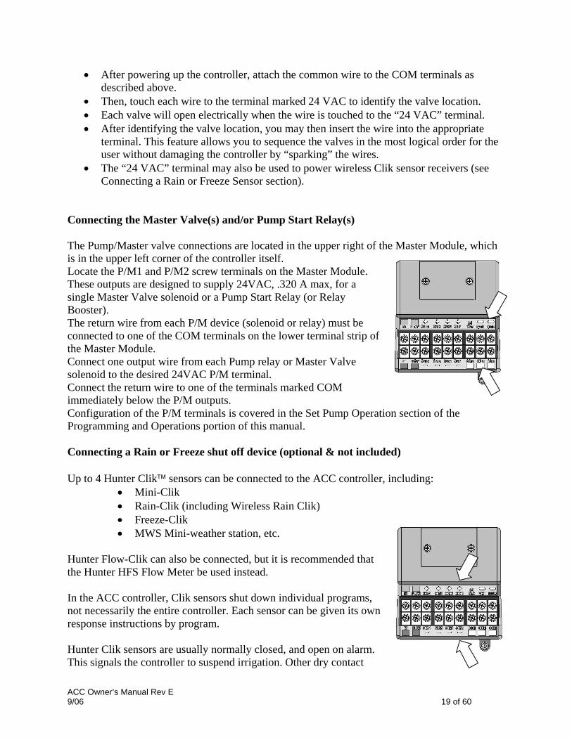
• After powering up the controller, attach the common wire to the COM terminals as described above.
• Then, touch each wire to the terminal marked 24 VAC to identify the valve location. • Each valve will open electrically when the wire is touched to the “24 VAC” terminal. • After identifying the valve location, you may then insert the wire into the appropriate
terminal. This feature allows you to sequence the valves in the most logical order for the user without damaging the controller by “sparking” the wires.
• The “24 VAC” terminal may also be used to power wireless Clik sensor receivers (see Connecting a Rain or Freeze Sensor section).
Connecting the Master Valve(s) and/or Pump Start Relay(s) The Pump/Master valve connections are located in the upper right of the Master Module, which is in the upper left corner of the controller itself. Locate the P/M1 and P/M2 screw terminals on the Master Module. These outputs are designed to supply 24VAC, .320 A max, for a single Master Valve solenoid or a Pump Start Relay (or Relay Booster). The return wire from each P/M device (solenoid or relay) must be connected to one of the COM terminals on the lower terminal strip of the Master Module. Connect one output wire from each Pump relay or Master Valve solenoid to the desired 24VAC P/M terminal. Connect the return wire to one of the terminals marked COM immediately below the P/M outputs. Configuration of the P/M terminals is covered in the Set Pump Operation section of the Programming and Operations portion of this manual. Connecting a Rain or Freeze shut off device (optional & not included) Up to 4 Hunter Clik™ sensors can be connected to the ACC controller, including:
• Mini-Clik • Rain-Clik (including Wireless Rain Clik) • Freeze-Clik • MWS Mini-weather station, etc.
Hunter Flow-Clik can also be connected, but it is recommended that the Hunter HFS Flow Meter be used instead. In the ACC controller, Clik sensors shut down individual programs, not necessarily the entire controller. Each sensor can be given its own response instructions by program. Hunter Clik sensors are usually normally closed, and open on alarm. This signals the controller to suspend irrigation. Other dry contact
ACC Owner’s Manual Rev E 9/06 19 of 60

closure sensors can be used without warranty, provided that a) they require no voltage and b) open the circuit when a shutdown condition is sensed. Hunter makes no claims or representations that such connections will be effective.
• To connect Clik sensors, locate the SEN [1-4] terminals on the Master Module (upper right corner of controller).
• Route the pair of wires from each sensor into the cabinet through one of the low voltage conduit openings in the bottom of the enclosure.
• The sensor connections are made in dedicated pairs: one wire to the sensor number + terminal, the other wire from the sensor to its – terminal. Do not twist common wires together from different sensors and connect them to the same terminal.
• Loosen the screw for the first sensor terminal (SEN1), and connect either of its wires to the + terminal and tighten.
• Connect the other wire from that sensor to the SEN1 – terminal and tighten. • To connect the wireless Rain Clik (WRC) or wireless Rain-Freeze Clik receiver, consult
the instructions supplied with the WRC for mounting and addressing. • Connect either of the receiver’s Yellow power wires to the “24 VAC” terminal on the
Master Module (the “24 VAC” terminal has a 400mA maximum capacity and is adequate for Clik receivers).
• Connect the other Yellow receiver wire to any of the COM terminals. • Complete the wireless Clik installation according to the WRC instructions.
All additional programming is performed at the facepack and is described in the Set Sensor Operation section of Programming and Operations.
• Connecting the ET Module (optional & not included) To connect a Hunter ET System to the ACC controller, use the adapter supplied with the ET System made especially for ACC. The adapter has SmartPort pins to align with the SmartPort plug on the upper left of the controller. It also has a color-coded terminal strip for ET System under its back cover. All ET System connections must be made at the wiring terminals in the adapter. The adapter is then pressed into place on the ACC SmartPort connector. This allows ET System to remain operational, while providing at the same time for ICR (or SRR) remote receiver installation. Connecting the Hunter Flow Sensor (optional & not included) The Hunter HFS Flow Meter is the primary flow meter for which ACC flow functions have been designed. Additional types of flow sensor connections may also be possible. Consult flow sensor mfor wiring and calibration information.
anual
ACC Owner’s Manual Rev E 9/06 20 of 60

• To connect a Hunter HFS Flow Sensor, route the pair of 18AWG (1mm) wires from the sensor into the cabinet through one of the low voltage conduit openings in the bottom of the enclosure.
• Locate the “Flow” red and black coded terminals near the left side of the Master Module. Connect the red wire from the HFS to the red terminal, and the black wire from the HFS to the black terminal.
• Reversing the red and black connections will probably not damage the units, but will not allow the ACC to read flow.
• Flow setup, learning, and configuration is described in the Set Flow Monitoring section of Programming and Operations.
• Connecting other Flow Sensors (optional & not included)
Some other brands or models of flow sensors may be compatible with the ACC controller. One known-compatible model is Data Industrial model IR-220B (also sold as Hunter model GENDATFL). Note: The ACC flow sensor connection is a 20 VDC pulsed output which senses interruptions as “clicks”. It is DC voltage, and the polarity must be observed. The red + terminal corresponds to the red wire on the HFS sensor, and if connecting to other brands of sensor insure that correct polarity is observed. Connect the positive (+) wire to the red Flow terminal on the Master Module, and the negative – wire to the black terminal. ICR Remote Control (optional & not included) The ACC controller has an integrated SmartPort® on the cabinet’s upper left side, or inside the front panel of the plastic pedestal. This connection is automatically compatible with Hunter ICR and SRR remote receivers. To connect: remove the weather-resistant rubber cover (metal cabinet versions), align the remote receiver’s pins with the mating receptacle, and push firmly until the receiver is fully seated. If the ET System adapter is installed, plug the receiver into the mating connector on the adapter. If the receiver address is to be changed, hold in the green button while plugging the receiver into the SmartPort, in accordance with the ICR instructions. WATERING AT 10:11:16
Sta Mode Time 03 ICR 0:03:56
Refer to the remote control’s instructions for additional addressing and operations. However, there are some significant differences in operating the remotes with the ACC controller, from previous Hunter controllers.
ACC Owner’s Manual Rev E 9/06 21 of 60

When a program or station is started by ICR, the ACC display will (as always) show why the program or station is running. Remote starts are followed by “ICR” in the display. To set up an ICR remote control for operations with ACC, consult the ICR instructions. Use the Mode button on the ICR transmitter to select a station size of “240” to allow access to all ACC programs and stations. Multiple Stations simultaneously: ACC is an overlapping controller, and will allow up to 6 stations to run simultaneously. While other Hunter controllers will stop existing stations when a new ICR remote start command is received, the ACC will continue to run existing stations along with the new stations, until the maximum of 6 events has been reached. If 6 events are running and an ICR command is received to start another, the command will be ignored. No new remote commands will be accepted until one of the 6 events times out. ACC can therefore run automatic programs, manual station and programs, and ICR commands simultaneously. Each running event will be shown on the display with the reason for running (programs will be shown with the program letter followed by “ICR” if they were started by the remote), and the remaining time for the event. The display shown here is possible with ACC: six events are running, including ICR station starts (ICR), ICR program starts (A-ICR), manual single-stations (MAN), manual program starts (C-MAN), and an automatic program (D-AUTO).
WATERING AT 10:11:16 Sta Mode Time
03 ICR 0:03:56 11 A-ICR 0:04:12 20 B-ICR 0:08:09 05 C-MAN 0:04:38 24 D-AUTO 0:01:12 06 MAN 0:14:22
If simultaneous operation is not desired, press the Off button on ICR before starting another program or station. Off will stop everything the controller is running, regardless of what started it. Stacking and SmartStack rules are NOT observed when ICR commands are sent to the ACC. The controller will start any station or program sent by ICR until the maximum of six is reached. ICR commands will also be obeyed if the controller is in the OFF position, or in a sensor shutdown mode. ACC will always respond to ICR commands unless 6 events are already running.
• Connecting to IMMS, the Hunter Irrigation Management and Monitoring System (optional & not included)
Available October, 2006.
• Power Failures
ACC Owner’s Manual Rev E 9/06 22 of 60

The ACC’s real time clock is independent of external power or the 9VDC battery, and will keep time during a power failure of virtually any length. When external power is restored, the ACC will still have the correct time and will be ready to irrigate. A Power Outage message will be stored in the Alarm Log, with time of the outage. Another log is stored when power is restored. Quick Start For experienced operators, the fastest steps to initial programming are as follows.
Set Current Date/Time: Use the arrow buttons to navigate, and the +/- buttons to change. Set the Date and Time and choose Units of Measure.
Set Watering Start Time: Each automatic Program has 10 start times. At this position, use the Programs button to select individual programs, and the 10 possible start times for that program will appear. Use arrows to navigate and +/- to change (see Program Overlap Options for important differences in ACC operations).
Set Station Run Times: At this dial position, use the Programs button to select the program you are setting up. Then, use the +/- buttons to change the hours:minutes:seconds run time for each station. Use the up and down arrows to move to the next station. TIP: Use the Copy and Paste buttons to move quickly through large numbers of similar stations. Set the first station’s run time, then press Copy. Use the Up arrow to move to the next station, and press Paste.
Set Days to Water: Use the Programs button to select the Program. Use the arrows to move to Day Sched, and choose Schedule Type (Day of Week, Interval, or Odd/Even).
Set Pump Operation (optional): The two Pump/Master Valve outputs may be set by station at this position. If no pump or Master Valve is in use, this is not required.
Return the dial to the Run position. This is all that is required for the most basic operations. ACC will water automatically in any dial position except “OFF”.
TEST: The Test program will start every station in the controller sequentially, in numerical order, for the specified time (from 1 second to 10 minutes). Turn the dial to the Run position. Test is started by holding down the Programs button for 3 seconds. Enter the Test time and wait 5 seconds for the Test cycle to begin. Each station LED on the output modules will light green when a station is running, red if a fault is detected. Test actually starts stations, and this will cause actual watering in a fully installed system.
Manual Start: Turn the dial to the Manual Operation dial position to manually start any Program, or single station. When the display shows Manual Program, use the Programs button to select the Program, and turn the dial to the Run position. The program will start in a few seconds. TIP: You can also hold down the right arrow button for 3 seconds to shortcut to Manual starts.
To start a Single Station: When “Program” is flashing, use the + button to change to Manual “One Station”. Use the down arrow to move to the station number, and +/- to select a station. Use the down arrow to move to the run time, and +/- to change the run
ACC Owner’s Manual Rev E 9/06 23 of 60

time (hh:mm:ss format, from 1 second to 6 hours). Turn the dial back to the Run position, and the station will start within a few seconds.
ACC Owner’s Manual Rev E 9/06 24 of 60

Controller Programming and Operation Using the Information button The Information button is used to provide programming tips, summary information and/or to unlock hidden features, depending on the dial position. If a flow meter is installed, press the Information button (with dial in the Run position) to see actual flow at any time. If the backlit display turns off while you are programming (it will time out after 5 minutes of inactivity), press the Information button to relight it (to prevent accidental changing of any settings by pressing the other keys). Pressing and holding the Information button will change the screen to either a summary screen of that dial position or will provide a programming tip. Releasing the button will return you to the normal programming screen for that dial position. Some dial positions have hidden features that are accessible by holding down the Information button, and then turning the dial to that position. This will unlock the hidden features. Hidden features are features that are protected from accidental re-programming because they are critical to the proper operation of the controller. Programming these hidden features is explained in the Hidden Features section. The ACC has the following Hidden Features: No Water Window
Delay between Stations Making the M/V circuit Normally On (instead of Normally Off) Setting the Flow Sensor size and type SSG (Simultaneous Station Group) setup Custom Manual program setup Test Program Easy Retrieve™ backup
Setting current Date and Time Three items are programmed at this position:
• Time of Day and Date, the day of the week sets automatically • Daylight Savings time usage • Units of measure, English or Metric
• Turn the dial to the SET CURRENT DATE/ TIME position • Press the + or – button to change the value of the flashing cursor. Hold the button down
to advance rapidly over a large range of numbers. • Press the arrow buttons to change cursor position. Set the hour and the minutes, then
advance to the AM/PM field. Use + or – to select AM, PM, or 24 hour clock (international, or “military” time). If 24 hour clock is selected, Program Start Times and other controller times will also be displayed in 24 hour format.
• Press the arrow buttons to advance and set the date in MM/DD/YY format.
ACC Owner’s Manual Rev E 9/06 25 of 60

• Advance to Daylight Saving and use +/- to select YES or NO. If YES, time will offset one hour at 2 AM on the last Sunday of April and October.
• Units of Measure: choose English or Metric. This will set the unit type for the entire controller.
Setting Program Start Times Three items are programmed at this position: START TIMES
PROGRAM A STACK
1-02:11AM 6-OFF 2-OFF 7-OFF 3-OFF 8-OFF 4-OFF 9-OFF 5-OFF 10-OFF
• Overlap or Stack start time priority • Start times for each of the six programs (A
– F) • Hidden Feature: No Water Window
Setting Program Start Times
• Turn the dial to the SET PROGRAM START TIMES position
• Select the Program (A – F) by pressing the Program button • Select Stack or Overlap for the Program. • Press the + or – button to change the value of the flashing cursor • Press the arrow buttons to change cursor position • The copy and paste buttons may be used to speed up programming (press the Copy
button at any Start Time position, then move to another position and press the Paste button- the same Start Time will be pasted there).
Stacked Start Times Stacking means that programs are not allowed to overlap; if one Program is set to start before another Program has completed, it will be pushed back (“stacked”) regardless of its actual start time. Each of the six programs (A – F) has ten start times available, for a total of sixty available automatic starts. The default is to stack the start times in alphanumeric order. (Program A will read Overlap, but all other programs will read Stack). For instance, start time “Program A at 8:15 AM” would start before “Program B at 8:15 AM” because A comes before B. The Start Time for Program B at 8:15 AM would start following the completion of Program A’s watering. Overlapping Start Times Overlapping start times allows more irrigation to occur simultaneously. Overlap starts Programs at their exact Start Times, regardless of other Programs that may be running (it is the opposite of Stacking). All six programs can be programmed to Overlap and thus potentially run simultaneously. This is great when a short watering window is necessary and the hydraulics of the system allows for high total water flow.
ACC Owner’s Manual Rev E 9/06 26 of 60

CAUTION: Understand your irrigation system’s hydraulic restrictions before allowing programs to overlap. Overlapping programs may overdrive the hydraulics of your system. Overdriving your hydraulics will damage the components and result in inferior sprinkler performance. More advanced programming overlap options are available by turning the dial to the SET PROGRAM OVERLAP OPTIONS dial position. Normally, the cursor will be positioned at the first Start Time hour position when turning the dial to the Set Program Start Time position.
START TIMES PROGRAM A
STACK 1-02:11AM 6-OFF 2-OFF 7-OFF 3-OFF 8-OFF 4-OFF 9-OFF 5-OFF 10-OFF
• To change the Stack/Overlap settings for the Program, use the arrow key to navigate up to the Stack/Overlap indication.
• Use + or – to change between Stack and Overlap.
• Use the arrow keys to move back down to the Start Times if necessary.
To set Start Times for the Program, move to the Start Time number, and use the + or – buttons to set the hour, then minutes, and then AM/PM settings.
• If a Start Time is skipped (for example, a time is set for 1, 2 is left at OFF, and a time is set for 3), the Start Time will be accepted, but when returning to this dial position, the Start Times will be moved to a sequential order (the Start Time set for 3 will have been moved to 2). This is by design.
• If an earlier Start Time is set for a higher-numbered Start (for example, Start 1 is set to 4:00 AM, and Start 2 is set to 3:00 AM), when returning to this dial position the Start Times will have been reorganized in chronological order. The lowest numbered Start Time will always have the earliest time of day (in the example, Start 1 will be at 3:00 and Start 2 will be at 4:00).
Press the Information button while in the Set Watering Start Times position to show a summary of all Start Time information for the selected Program. This will show number of starts, time per start, and total time for the program. No-Water Window
• Programming this feature is explained in the Hidden Features section. Setting Station Run Time Duration
RUNTIME PROGRAM A
PROG A SEAS ADJ 100% _____________________________
STATION 01 PROGRAMMED ACTUAL 0:00:00 0:00:00
Three items are programmed at this position: • Station watering duration • Seasonal Adjust value for the Program • Hidden Feature: Timed Delay between
Stations Setting Station watering duration
ACC Owner’s Manual Rev E 9/06 27 of 60

• Turn the dial to the SET STATION RUN TIMES position • Select the Program (A – F) by pressing the Program button • Press the + or – button to change the value of the flashing cursor. The cursor initially
appears in the minutes field. • Press the right and left arrow buttons to change from minutes to hours or seconds cursor
positions. Set the run time in h:mm:ss format. • Run times may be from 1 second to 6 hours, or any increment in between. • Press the up and down arrow buttons to change to a different station number • The copy and paste buttons may be used to speed up programming.
NOTE: If the ACTUAL value is different from the PROGRAMMED value, Seasonal adjust has been changed from the default of 100% to a new value. The actual run time is the duration the station will water. Press the Information button with any station selected at the Set Station Run Times dial position to see a summary of all watering for a specific station, including all programs in which it will run. Changing Seasonal Adjust Season adjust is used to make global or program specific run time changes without the need to reprogram every station’s run time. Season adjust can either be global (GLBL) where all programs use the same value or program specific. Turn the dial to the SET STATION RUN TIMES position.
RUNTIME PROGRAM A
PROG A SEAS ADJ GLBL GLOBAL SEAS ADJ=100%
_____________________________STATION 01
PROGRAMMED ACTUAL 0:00:00 0:00:00
Using the Global setting: • Press the left arrow button until the cursor is on
the percentage below the GLBL. The percentage immediately below GLBL is the seasonal adjustment percentage for the entire controller.
• Press the + and – buttons to adjust the global season adjust value between 0 and 300%.
Using a program specific setting (set Season Adjust by Program):
• Press the left arrow button until the cursor is on the GLBL. • Press the + and – buttons to adjust the season adjust value between 0 and 300%. • NOTE: If it is desired to return to the global season adjust, move the cursor to the season
adjust percentage then use the + and – buttons to change the value to GLBL. GLBL is located between the 101 and 100% positions.
Timed Delay between Stations
• Programming this feature is explained in the Hidden Features section. Setting Days to Water
ACC Owner’s Manual Rev E 9/06 28 of 60
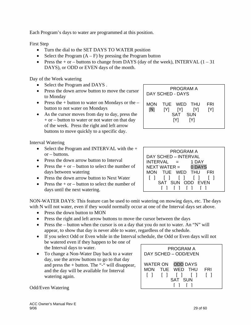
Each Program’s days to water are programmed at this position. First Step
• Turn the dial to the SET DAYS TO WATER position • Select the Program (A – F) by pressing the Program button • Press the + or – buttons to change from DAYS (day of the week), INTERVAL (1 – 31
DAYS), or ODD or EVEN days of the month. Day of the Week watering
• Select the Program and DAYS . PROGRAM A
DAY SCHED - DAYS
MON TUE WED THU FRI [N] [Y] [Y] [Y] [Y]
SAT SUN [Y] [Y]
PROGRAM A DAY SCHED – INTERVAL INTERVAL = 1 DAY NEXT WATER = 0 DAYS MON TUE WED THU FRI [ ] [ ] [ ] [ ] [ ]
SAT SUN ODD EVEN [ ] [ ] [ ] [ ]
• Press the down arrow button to move the cursor to Monday
• Press the + button to water on Mondays or the – button to not water on Mondays
• As the cursor moves from day to day, press the + or – button to water or not water on that day of the week. Press the right and left arrow buttons to move quickly to a specific day.
Interval Watering
• Select the Program and INTERVAL with the + or – buttons.
• Press the down arrow button to Interval • Press the + or – button to select the number of
days between watering • Press the down arrow button to Next Water • Press the + or – button to select the number of
days until the next watering. NON-WATER DAYS: This feature can be used to omit watering on mowing days, etc. The days with N will not water, even if they would normally occur at one of the Interval days set above.
• Press the down button to MON • Press the right and left arrow buttons to move the cursor between the days • Press the – button when the cursor is on a day that you do not to water. An “N” will
appear, to show that day is never able to water, regardless of the schedule. • If you select Odd or Even while in the Interval schedule, the Odd or Even days will not
be watered even if they happen to be one of the Interval days to water. PROGRAM A
DAY SCHED – ODD/EVEN WATER ON ODD DAYS MON TUE WED THU FRI [ ] [ ] [ ] [ ] [ ]
SAT SUN [ ] [ ]
• To change a Non-Water Day back to a water day, use the arrow buttons to go to that day and press the + button. The “-“ will disappear, and the day will be available for Interval watering again.
Odd/Even Watering
ACC Owner’s Manual Rev E 9/06 29 of 60

• Select the Program and ODD/EVEN with the + or – buttons, as shown above in First Step • Press the down arrow button once, to select Odd or Even. • Press the + or – button to toggle between ODD or EVEN day watering
NON-WATER DAYS: This feature is frequently used to omit watering on mowing days, etc. • Press the down button to MON • Press the right and left arrow buttons to move the cursor between the days • Press the – button when the cursor is on a day that you do not to water. An “N” will
appear, to show that day is never able to water, regardless of the schedule. • To change a Non-Water Day back to a water day, use the arrow buttons to go to that day
and press the + button. The “-“ will disappear, and the day will be available for Odd or Even watering again.
Setting Pump and Master Valve Operation Two items are programmed at this position:
• Pump or Master Valve (P/MV) operation by station. Each station may have any combination of P/MV outputs 1, 2, both, or neither, which will activate as specified whenever the station is turned on.
• Hidden Feature: Change the master valve from the default of normally closed (N.C.) to normally open (N.O.)
Setting Pump and Master Valve Operation
• Turn the dial to the SET PUMP OPERATION position • Press the right and left arrow buttons to move between P/MV 1 and P/MV 2 • Press the up and down arrow buttons to change the station number • Press the + or – button to enable or disable the specific Pump or Master Valve for the
given station Changing from normally closed to normally open
• Programming this feature is explained in the Hidden Features section. Setting Station Cycle and Soak durations Each Station’s Cycle and Soak settings are programmed at this position. Cycle and Soak allows the user to break up the total run time of a station into more usable watering durations (cycles), and a minimum soak time between the watering cycles. This feature is great to use on slopes and tight soils because it puts the water down more slowly, helping to prevent run off.
CYCLE & SOAK _____________________________
STATION 01 CYCLE SOAK
(H:MM) (H:MM) 0:01 0:01
Setting Station Cycle and Soak durations
• Turn the dial to the SET CYCLE AND SOAK position
• Press the up or down arrow keys to change stations
ACC Owner’s Manual Rev E 9/06 30 of 60

• Press the right and left arrow buttons to move between hours and minutes and cycle and soak
• Press the + or – button to change the Cycle cursor value. The default cursor value is N/A. Cycles can be set from 1 minute to 6 hours.
• Press the right arrow button to move from Cycle to Soak, once a value has been entered into the Cycle field.
• Press the + or – button to change the Soak cursor value. The default cursor value is N/A. Soaks can be set from 1 minute to 9 hours.
• Press the down arrow to move to the next station. • The Copy and Paste functions are useful for large numbers of stations with similar Cycle
and Soak requirements. To use, set a station’s Cycle and Soak information, then press the Copy button.
• Use the up or down arrows to advance to the next station, and press Paste. Both the Cycle and Soak value will be pasted into the fields.
You can continue to advance through the stations with the up or down arrows, and press Paste to continue pasting the same Cycle and Soak values into subsequent stations. Cycle and Soak Summary: In the Set Cycle and Soak dial position, press the Information button to view a summary of Cycle and Soak with any selected station’s run time. It will display the number of Cycles the station will run with the current settings. Setting Flow Monitoring
FLOW OPERATION SENSOR = HFS FCT100
STATION 01
FLOW LMT DELAY (GPM) (M:SS)
NOT LEARNED
The ACC is capable of monitoring, learning, and reacting to Real-Time flow. The installation of the optional Hunter Flow Sensor (HFS) or a Data Industrial flow sensor is required for this feature to function. The ACC must first learn the normal flow, by station, for flow sensing to operate correctly. Step 1: Select the flow sensor
• Press and hold the INFORMATION button while you turn the dial to the SET FLOW MONITORING position
FLOW OPERATION __________________________
EDIT LEARNED FLOW
SELECT FLOW SENSOR Press ‘+’ to select.
FLOW OPERATION SENSOR = HFS FCT158
‘+’ or ‘-‘ to change..
• Press the down arrow button once so the cursor blinks on SELECT FLOW SENSOR.
• Press the plus button until the correct HFS FCT size is displayed. HFS sensors are always installed in a Hunter FCT fitting, and selecting the fitting size automatically sets calibration for sensor (see sensor installation instructions).
• If you are using a Data Industrial or similar Flow Sensor, press the plus button until OTHER is in the display. Then use the plus, minus and arrow buttons to set the K-Factor
ACC Owner’s Manual Rev E 9/06 31 of 60

and Offset. These values can be found in the Data Industrial or similar suppliers’ literature.
Menu choices: FCT size Pipe dia. Pipe Class
100 1” Sch. 40 150 1.5” Sch. 40 158 1.5” Sch. 80 200 2” Sch. 40 208 2” Sch. 80 300 3” Sch. 40 308 3” Sch. 80 400 4” Sch. 80
OTHER K-factor & offset
K-factor & offset
• Once the flow sensor is selected, turn the dial off the SET FLOW MONITORING position, to any other dial position.
Step 2: Viewing Real-Time Flow
FLOW NOT LEARNED _____________________________
WATERING STATIONS 04, 06
ACTUAL FLOW 20.1GPM [display with Information pressed]
• Once the flow meter is configured, ACC can display real time flow. Turn the dial to the Run position, and press and hold the Information button.
• The display will show which stations, if any, are running, and the current flow (in gallons or liters per minute, depending on your Unit of Measure settings).
• The flow display is not updated while the Information button is pressed. To see an updated view of changing flow conditions, release the Information button and press again after a few seconds. Each press of the button updates the display with the latest flow.
• If individual station flows have not been learned (see step 3), the display will show FLOW NOT LEARNED as a reminder that station-level alarm diagnostics are not available yet. The actual flow may still be viewed, even if flow is not learned.
• If the flow sensor selection has been changed to NONE after learning, the display will show FLOW NOT MONITORED. The actual flow may still be viewed, even if all stations have been set to Not Monitored. Station level alarm diagnostics would not be available, but the flow will be visible.
Step 3: Preparing for Flow Learning • ACC will only learn flows for stations which have run times in Automatic Programs.
Verify that each station has a run time in an Automatic Program (A through F). • ACC can be taught to ignore flow monitoring for stations which operate non-irrigation
devices. • Turn the dial to another position, then hold the Information button while turning
back to the Set Flow Monitoring position. • Select Edit Learned Flow (even if no flow has been learned, yet).
ACC Owner’s Manual Rev E 9/06 32 of 60

• Use the – button to set the non-irrigation stations to Not Monitored. Use the up and down arrow buttons to advance through the stations, and set any stations necessary to the Not Monitored setting.
6:46:04 AM MONDAY 3/07/06
LEARN STATION FLOW
This will turn on stations to learn. Are you SURE?
‘+’ =YES : ‘-‘ =NO
Step 4: Learning the flow
• Turn the dial back to the RUN position. • Press the LEARN button. The display will ask
you to confirm that you want to begin watering to learn flow.
• The ACC will begin watering at the lowest station number to learn its typical flow. Normally this will be station 01, unless it is Not Monitored or has no run time in any programs.
6:46:04 AM MONDAY 3/07/06
**LEARN MODE** PLEASE STAND BY…
• It will run the station for a minimum of 15 seconds, and then begin sampling flow at 5-second intervals until flow has stabilized (at least 4 readings, 5 seconds apart, within a reasonable flow range of one another). It will then store the average flow for this station in its memory, and move on to the next station. It will continue in this manner through all stations which have at least one run time in one of the Automatic Programs, and which are not set to Not Monitored in the Set Flow Monitoring station settings.
WATER AT 6:46:37 Sta Mode Time
01 LEARN 0:05:00
Only stations with a run time in an Automatic Program will be learned. Stations which are not programmed in any Programs will not be sampled, and should be set to Not Monitored (see below) to insure proper operation of the flow meter. If the station Delay setting has been changed, the controller will run the station for Delay period (instead of the 15 second minimum) before sampling and learning flow.
• It may take a full hour or longer to learn flows for an entire 42-station controller. Each station may take from 35 seconds to 5 minutes to be learned, depending on stability of the flow.
Step 4: Review and Edit Flow. The flow values and settings for each station can be reviewed, and manually edited, at the Set Flow Monitoring dial position. It is important to verify the flow settings for each station before leaving the controller in automatic operation.
• Turn the dial to the Set Flow Monitoring position. • Use the up and down arrows to navigate through all stations, and verify that they have a
learned flow or a Not Monitored setting.
ACC Owner’s Manual Rev E 9/06 33 of 60

• Do not leave any station with a “Not Learned” message- either enter a flow manually, or set it to Not Monitored.
• To edit a station’s flow data, turn the dial to any other position, hold down the Information button, and turn the dial back to the Set Flow Monitoring position.
• Use the up and down arrow buttons to move through each station.
• Use the +/- buttons to adjust the flow. Each station can be set from 0.5 GPM(1.9LPM) to 999.5 GPM(2770LPM) in .5 GPM /1.9LM increments. Between the highest value (999.5) and the lowest (0.5/1.9LPM), the Not Learned and Not Monitored choices also appear, as the +/- buttons are pressed.
FLOW OPERATION SENSOR = HFS FCT100
STATION 01
FLOW LMT DELAY (GPM) (M:SS)
15.0 115% 0:15
You can manually replace a Learned flow with another value, if you wish.
• LIMIT: Use the left and right arrow buttons to move to the Limit field (LMT) to edit it, if desired.
The default Limit is always 115%, meaning the station must exceed the flow by 15% before it will be treated as an alarm (to prevent false alarms due to normal flow fluctuations). 110% is the minimum possible Limit setting, and 300% is the maximum.
• DELAY: Use the left and right arrows to move to the Delay setting to edit it, if desired. The default delay is 01:00 in minutes:seconds format. This means the station’s flow will be ignored for the first 1:00 of operation, before the flow will be considered for alarm purposes. The Delay can be set from 0:15 to a maximum of 9:59. Some delay is recommended to prevent false alarms, particularly when stations are initially activated.
• Review all stations to verify their flows, limits, and delays. • Once station flows have been learned, flow
monitoring is in effect. If the Information button is pressed during irrigation, the actual flow will be shown, along with the combined limit of all active stations.
FLOW MONITORING _____________________________
WATERING STATIONS 04, 06
ACTUAL FLOW LIMIT 20.1GPM 25GPM [display with Information pressed]
• Stations that do not operate irrigation devices, and stations that are not used, must be set to Not Monitored to avoid false alarms.
Flow Alarms Once station flow has been learned, ACC will always compare actual flow from the flow meter to the learned flow (even when multiple stations are running). When the actual flow exceeds the limit over learned flow, after the specified delay has elapsed, an alarm will occur.
ACC Owner’s Manual Rev E 9/06 34 of 60

When a Flow Alarm has been detected, the display will show the Fault, Flow Alarm message during the remainder of the automatic programs. Diagnostic routines will begin, and you can view them by pressing the Information button. After irrigation is completed, the display will continue to show that alarms occurred, until any button is pressed. This will usually result in multiple flow alarms since ACC will try to restart stations after Pausing for one minute. Since ACC can run multiple stations at once (Overlap, SSGs, etc.), it will add up the learned flows for all stations that are running, and compare the total to the actual flow, in real time. If an alarm occurs with multiple stations, ACC will enter a diagnostic mode to try to isolate the problem stations. All station delays must be met before the alarm will occur. If multiple stations are running and have different delay times set for Flow Alarm limits, the longest delay must be met before the alarm will occur. To view the diagnostics while they are in progress, press the Information button. This will clear the Fault, Flow Alarm display and show the actual status of the affected stations. While isolation is in progress, the display will then show individual stations in Pause status, as each station’s flow is sampled one at a time.
WATERING AT 03:11:23
FAULT FLOW ALARM
WATERING AT 03:11:23
FAULT FLOW ALARM
7:57:03 THURSDAY 5/11/06
FAULT FLOW ALARM FLOW ALARM
FLOW ALARM FLOW ALARM
Alarm Logs (also see Historical Data/Data History section) When a Flow Alarm is shown on the display, turn the dial to Data History to view the Alarm Logs for an explanation of the alarm (select Alarm Logs and press +). The Last Event is always shown first. Press the – button to step backwards through the logs to view them one at a time. A Missed Irrigation report will be logged for each station event that causes a station to shut down for Overflow or Underflow reasons. The report will show the date and time of the event, and which type of flow alarm occurred (Over or Under). Tips on Flow Alarms:
• There is only one flow meter per ACC controller, and controllers do not share information with one another. If a controller with a meter “sees” flow caused by another controller, drawing water from the same point of connection to the water supply, the controller will experience many false alarms, because it cannot account for the flow. Do not combine controllers on the same point of connection.
ACC Owner’s Manual Rev E 9/06 35 of 60
• Sometimes a Fault will be shown, but no flow alarm log appears in the Alarm Logs. This can happen when a station encounters high or low flow near the end of its schedule run time, and there is not enough run time left on the station to complete the diagnostics. The controller will abandon the diagnostics after the station’s total run time is finished to avoid prolonged watering.
• Most false alarms occur because the Limit % is set too close to “normal” or learned flow. Irrigation systems often experience fluctuations in the amount of flow and increasing the limit % reduces the possibility of false flow alarms.
• The primary purpose of Underflow alarms is to protect a Pump from deadheading, if a station has failed to open. If a station that has learned flow is activated for test purposes without turning on an actual valve, an Underflow alarm may occur. This is normal.
• When two stations are running together with very different flows, such as a high volume spray or rotor zone running together with a low-volume drip zone, it is possible that an alarm condition on the low flow zone may be missed. This is because the Limit % of the high flow zone may include the entire flow range of the low flow zone. For example, a 40 gpm zone with a limit of 115% needs to see 46 gpm to alarm. If it is running together with a 4gpm drip zone set to 115%, the drip zone could exceed its alarm limit (4.6 gpm) but the total would still be under the combined alarm limit for both stations.
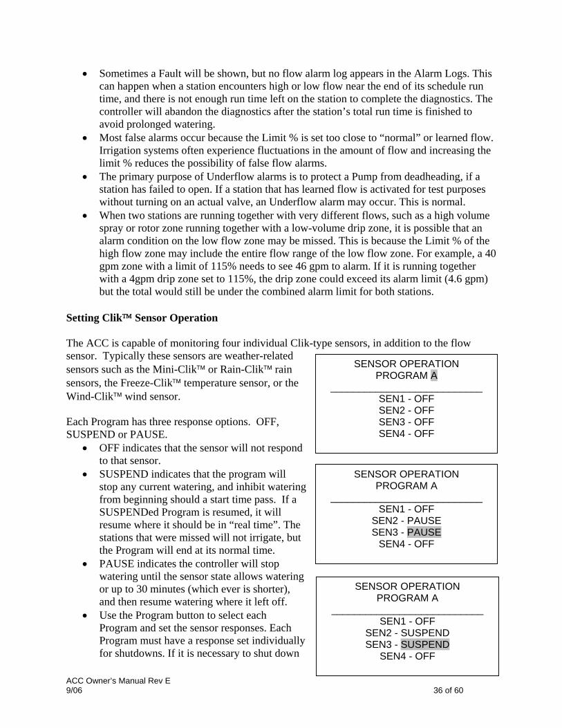
Setting Clik™ Sensor Operation The ACC is capable of monitoring four individual Clik-type sensors, in addition to the flow sensor. Typically these sensors are weather-related sensors such as the Mini-Clik™ or Rain-Clik™ rain sensors, the Freeze-Clik™ temperature sensor, or the Wind-Clik™ wind sensor. Each Program has three response options. OFF, SUSPEND or PAUSE.
• OFF indicates that the sensor will not respond to that sensor.
• SUSPEND indicates that the program will stop any current watering, and inhibit watering from beginning should a start time pass. If a SUSPENDed Program is resumed, it will resume where it should be in “real time”. The stations that were missed will not irrigate, but the Program will end at its normal time.
• PAUSE indicates the controller will stop watering until the sensor state allows watering or up to 30 minutes (which ever is shorter), and then resume watering where it left off.
• Use the Program button to select each Program and set the sensor responses. Each Program must have a response set individually for shutdowns. If it is necessary to shut down
ACC Owner’s Manual Rev E 9/06 36 of 60
SENSOR OPERATION PROGRAM A
___________________________ SEN1 - OFF SEN2 - OFF SEN3 - OFF SEN4 - OFF
SENSOR OPERATION PROGRAM A
___________________________ SEN1 - OFF
SEN2 - PAUSE SEN3 - PAUSE
SEN4 - OFF
SENSOR OPERATION PROGRAM A
___________________________ SEN1 - OFF
SEN2 - SUSPEND SEN3 - SUSPEND
SEN4 - OFF
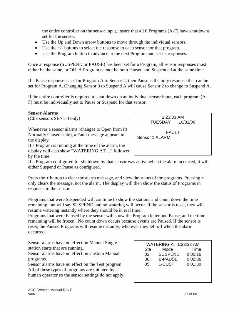
the entire controller on the sensor input, insure that all 6 Programs (A-F) have shutdowns set for the sensor.
• Use the Up and Down arrow buttons to move through the individual sensors. • Use the +/- buttons to select the response to each sensor for that program. • Use the Program button to advance to the next Program and set its responses.
Once a response (SUSPEND or PAUSE) has been set for a Program, all sensor responses must either be the same, or Off. A Program cannot be both Paused and Suspended at the same time. If a Pause response is set for Program A to Sensor 2, then Pause is the only response that can be set for Program A. Changing Sensor 3 to Suspend A will cause Sensor 2 to change to Suspend A. If the entire controller is required to shut down on an individual sensor input, each program (A-F) must be individually set to Pause or Suspend for that sensor. Sensor Alarms (Clik sensors SEN1-4 only) Whenever a sensor alarms (changes to Open from its Normally Closed state), a Fault message appears in the display. If a Program is running at the time of the alarm, the display will also show “WATERING AT…” followed by the time. If a Program configured for shutdown by that sensor was active when the alarm occurred, it will either Suspend or Pause as configured. Press the + button to clear the alarm message, and view the status of the programs. Pressing + only clears the message, not the alarm. The display will then show the status of Programs in response to the sensor. Programs that were Suspended will continue to show the stations and count down the time remaining, but will say SUSPEND and no watering will occur. If the sensor is reset, they will resume watering instantly where they should be in real time. Programs that were Paused by the sensor will show the Program letter and Pause, and the time remaining will be frozen . No count down occurs because events are Paused. If the sensor is reset, the Paused Programs will resume instantly, wherever they left off when the alarm occurred.
1:23:33 AM TUESDAY 10/31/06
FAULT
Sensor 1 ALARM
WATERING AT 1:23:33 AM Sta Mode Time 02 SUSPEND 0:00:16 06 B-PAUSE 0:00:36 05 1-CUST 0:01:30
Sensor alarms have no effect on Manual Single-station starts that are running. Sensor alarms have no effect on Custom Manual programs. Sensor alarms have no effect on the Test program. All of these types of programs are initiated by a human operator so the sensor settings do not apply.
ACC Owner’s Manual Rev E 9/06 37 of 60

However, if an automatic Program (A-F) was started Manually, it will be shut down by an active sensor that is configured to shut down that program. The sample display on the right shows a single active sensor alarm in process, with a range of possible responses. The operator has pressed the + button after the FAULT display, to view controller status. Station 02 was running in Program A, and that Program has been Suspended (the seconds timer would still be counting, but watering would be stopped). Station 06 was running in Program B, and has been Paused. The seconds timer would be frozen (and watering would be stopped). Station 05 was running in a Custom Manual program, and the sensor would have no effect on it. Station 05 would still be watering in Custom Manual 1. There is no direct Override for a Clik sensor. Depending on what needs to be accomplished, the Test program is still available (for winterization functions) and individual stations can still be started from the Manual position. If a sensor is alarmed, and a Manual Program start is attempted for a Program with a response for that sensor, the display will show “CANNOT RUN MANUAL. A sensor is active for this program.” That program cannot be manually started until the sensor is reset. If full operations must be restored when a sensor is in alarm, turn the dial to the Set Sensor Operation position, and use +/- to change the sensor response to Off (by program). View recent alarms, or alarm history, by turning the dial to the Data History position and selecting Alarm Logs (see Data History). Setting Program Overlap Options There are three program overlap options. These options allow you to maximize the number of stations operating simultaneously, if the system’s hydraulics can support the flow. To program the Program Overlap option:
• Turn the dial to the SET PROGRAM OVERLAP OPTIONS position • Use the Up and Down buttons to navigate to changeable portions of each display. • Use the +/- buttons to see and set the choices.
Once the Program Overlap Option has been selected for the controller, individual programs can be set to Overlap or Stack at the Set Program Start Times position. Option One: Stack or Overlap
ACC Owner’s Manual Rev E 9/06 38 of 60

STACK means that the programs will run in alphanumeric order by Program letter and start time chronology. STACK is the default. OVERLAP means that each program will start at the time it is scheduled to start, regardless of what else is watering. Leaving this setting in the “Stack or Overlap” position means that each program can be set to Stack or Overlap, individually. A more detailed explanation of this option can be found in the Setting Program Start Times section of this manual. Option Two: Smartstack™ SmartStack will limit simultaneous operations to the number of stations specified here. The operator may program as many overlapping programs as desired, and the controller will permit overlap up to the number specified here, and stack the rest.
• Smartstack allows from two to five stations to operate simultaneously, before forcing additional stations into a stacked queue.
• Use the up and down arrow buttons to move to the number of stations allowed (after choosing SmartStack).
• Use the +/- buttons to set the number of stations allowed to overlap. This is a great way to minimize the watering window by allowing the controller to run at maximum electrical capacity, if you have sufficient water pressure and flow to support multiple programs. Option Three: SSG/Smartstack (see SSG Setup in the Hidden Features section for more information). An SSG (Simultaneous Station Group) is a group of up to four stations that water at the same time, for the same duration. Any 2 to 4 stations can be placed into an SSG, and from that time on, they will be programmed and operated as a single unit. Combining stations into SSGs shortens programming time, and can also shorten watering time (by running multiple stations at once). SSGs should normally combine similar stations, with similar watering needs and flows, to be used to their best advantage.
START TIME OPTIONS
STACK OR OVERLAP
Set each program to stack or overlap via start time screen.
START TIME OPTIONS
SMARTSTACK
Stack only after 5 stations
are running.
START TIME OPTIONS
SSG/SMARTSTACK
Stack only after 2 stations and
an SSG are running.
When using SSGs, the controller can electrically only handle one SSG, two stations, and two Master Valves simultaneously, maximum. You must
ACC Owner’s Manual Rev E 9/06 39 of 60

choose this option if you plan on using SSGs. If SSG/SmartStack is chosen:
• Use the up and down arrow buttons to navigate to the number of stations (allowed to overlap with an SSG).
• Use the +/- buttons to set the number of stations permitted to overlap an SSG. • Since an SSG may contain up to 4 stations, setting this number to “1” means that up to 5
stations may run at once (up to 4 in the SSG, plus one additional station). Setting the number to “2” means that up to 6 stations may run at once. Setting this to 0 means SSGs must run by themselves and may not overlap individual stations.
• ACC does not adjust overlap and stacking for SSGs which have fewer than 4 stations in them… it assumes that all SSGs have four stations, and the number of stations allowed with an SSG applies, regardless of the SSG’s actual size.
CAUTION: Understand your irrigation system’s hydraulic restrictions before allowing stations to Smartstack or SSG/Smartstack. Overlapping stations may overtax the hydraulics of your system. Overtaxing your hydraulics will damage the components and result in inferior sprinkler performance. Mixing dissimilar stations in SSGs may cause over or underwatering of certain plant types. Setting Station & Program Names All stations and programs of the ACC can be named for easy reference. This can either be setup via the IMMS central control software, or it can be programmed at the controller using the keypad. The Contact Info screen can also be programmed at this position. This sets the display which appears when the controller is turned on, and which also appears in many of the Information screens. The factory default setting is Hunter Industries contact information, but it can be replaced with the company name, telephone number, and/or web site of the appropriate installing or servicing personnel.
ASSIGN CONTACT INFO
HUNTER IND. INC. SAN MARCOS, CA.
760-744-5240 HUNTERINDUSTRIES.COM
ASSIGN CONTACT INFO
KENS WEATHERORNOT FRESNO, CA. 760-744-5240
KENSWEATHERORNOT.COM
To ASSIGN CONTACT INFO:
• Use the up and down arrow buttons to move down to the next line in the display (default name is “Hunter Industries”).
• Use the +/- buttons to select a letter, number, or character for each letter position. It is possible to reprogram a character right over the existing text.
• Hold the + or – button down continuously to advance rapidly through all choices, including capitals, lower case, numbers, and characters.
• Use the left and right arrow buttons to advance to the next character position, and select the next character.
ACC Owner’s Manual Rev E 9/06 40 of 60

• Continue until the line is complete. Use the arrow buttons to move down and reprogram each line.
• Turn the dial to any other position, at any time, to save the text in the Contact Info screen. ASSIGN PROGRAM NAMES
PROG A- LAWNS PROG B-SHRUBS PROG C-FLOWERS PROG D-PROGRAM D PROG E-PROGRAM E PROG F-PROGRAM F
To name a PROGRAM (up to 13 characters and spaces):
• Turn the dial to the SET STATION & PROGRAM NAMES position
• Press the PLUS button once • Use the up and down arrow buttons to select
the program you wish to name • Use the plus and minus buttons to select the
letter or symbol you wish to use. ASSIGN STATION NAMES
STA 01-SOUTH LAWN 1 STA 02-SOUTH LAWN 2 STA 03-WEST LAWN 1 STA 04-WEST LAWN 2 STA 05-AZALEAS STA 06-STATION 06
• Press the right arrow button to advance the cursor and then repeat, using the plus and minus buttons to select the next letter or symbol.
• Repeat until the name is completed. To name a STATION (up to 13 characters and spaces):
• Turn the dial to the SET STATION & PROGRAM NAMES position • Press the + twice, or the - button once. • Use the up and down arrow buttons to select the program you wish to name • Use the plus and minus buttons to select the letter or symbol you wish to use first, press
the right arrow button to advance the cursor and then repeat using the plus and minus buttons to select the next letter or symbol. Repeat until the name is completed.
HISTORICAL DATA _____________________________
• Shortcut: Use Copy and Paste for similar names, and change only the characters that are unique to the station.
FLOW TOTALS ALARM LOG
Press ‘+’ to select.• Turn to any other dial position to save names.
Historical Data/Data History
FLOW TOTALS-Gallons Select total to view
This dial position allows you to view flow totals and alarm logs. CONTROLLER
TODAY
0.0 YESTERDAY
Flow totals can be viewed for:
• The entire controller • An individual program (projected flow)
0.0• An individual SSG • Or an individual station.
ACC Owner’s Manual Rev E 9/06 41 of 60

Once the flow item is selected you can then view:
• The total for today and yesterday • Week to date & last week totals • Month to date and last month totals • Or Year to date and last year totals
To view flow totals:
• Turn the dial to the DATA HISTORY position • Press the plus button once HISTORICAL DATA • Press the plus or minus button until the item you
would like to view is displayed _____________________________
FLOW TOTALS • Press the down arrow button to highlight TODAY ALARM LOG
• Press the plus or minus button until the period
you would like to view is displayed Press ‘+’ to select. To view alarm logs:
• Turn the dial to the DATA HISTORY position • Press the down arrow button to select ALARM LOG • Press the plus button to view the log • Press the plus and minus buttons to scroll through the log. Alarms are logged by type of
alarm, and time and date of occurrence. • The Alarm Log will store up to the last 200 events (the oldest events are replaced by new
ones). Alarm log items labeled “Missed Irrigation” are important, because they have caused stations to not water when they should. The reason for the missed irrigation will always be indicated, as “Overcurrent” (electrical) or “Overflow/Underflow” (hydraulic), etc. Each alarm log entry will have the exact time of the occurrence of the missed irrigation event. Common Fault Messages Overcurrent: Station has exceeded .56 Amps output. This indicates that either too many solenoids are connected or the field wiring or solenoid has a problem, causing an unacceptably high current. All solenoids are different and not all solenoids may be “doubled” on an ACC output. A solenoid with a holding current of .3 A is acceptable, but two of them (equaling .6 A) would exceed the .56 A max limit and cause an Overcurrent.
ALARM EVENT REPORT 08/21/06 11:44:37P
_____________________________
POWER OUTAGE
‘+’ = nxt, ‘-‘ = prev
ALARM EVENT REPORT 08/21/06 06:32:14P
_____________________________MISSED IRRIGATION
Reason: Overflow Mode: Manual Prg All Sta: 005 – Prg: A
‘+’ = nxt, ‘-‘ = prev
P/MV outputs have a max output of .325 A. Pump start relays with very high current requirements may need a dedicated transformer and an additional relay (such as Hunter Model PSRB) for reliable operations.
ACC Owner’s Manual Rev E 9/06 42 of 60

Overflow: A station has exceeded its learned flow upper limit during irrigation. ACC totals the upper limit of the learned flow for all running stations, and compares them to the actual flow at the flow meter. When the combination of stations exceeds the total upper limits (after all Delay times have elapsed), the controller will Pause and go into alarm diagnostic mode. Alarm diagnostics consist of pausing all operations, then starting each station that was running at the time of the alarm individually. Each of these suspect stations has its flow sampled alone, to see if it caused the overflow. If the controller identifies a station as having high flow, it will create a Missed Irrigation report and attempt to continue watering with other stations. Underflow: A station has caused too little flow, indicating a possible problem. The underflow amount cannot be set directly, but is twice the percentage of the Limit amount set for overflow. If a station is set 115% for the upper limit (normal flow + 15%), then 70% will be the underflow amount (normal flow – 30%). Hidden Features No Water Window (INFORMATION+Set Program Start Time) No Water Windows prevent any automatic irrigation from occurring during certain hours, by Program. This can be used to protect high traffic areas from accidental programming, or the results of Seasonal Adjust, during busy times of day. Start in any other dial position, hold the Information button down, and turn the dial to Set Program Start Times. Release the Information button. The display will now permit programming of No Water Windows. To set a No Water Window: Use the Program button to select the program for which a No Water Window is desired. Use the +/- button to set the time for the beginning of the No Water Window (“FROM”) in hh:mm format, including AM/PM if applicable. Use the down arrow to move to the “TO” position, to set the end of the No Water Window. Use +/- to set the end of the window, also in hh:mm format. The No Water Window is now set. Use the Program button to set a No Water Window for another Program, or exit the dial position to save the settings. No Water Window rules: Each Program may have a different No Water Window. If the operator attempts to program a Start Time that falls withing a No Water Window, the display will flash a warning. If the warning is ignored, the Start Time will be saved, but will not run during the No Water Window.
NO WATER WINDOW
PROGRAM A _____________________________FROM – N/A TO – N/A
If a Program starts at a “legal” time, but runs past the beginnng of a No Water Window, irrigation will be stopped (display will show “Suspend”). If the No Water Window ends and the
ACC Owner’s Manual Rev E 9/06 43 of 60

program still has time left, the irrigation will resume where it should be for that time of day. Any irrigation that was suspended during the No Water Window will be missed. Programs that continue into a No Water Window because of Cycle & Soak settings, or because of Seasonal Adjust settings, will also be suspended. However, there will be no warning in the display when these changes are made at Cycle & Soak or Seasonal Adjust. Delay between Stations INFORMATION+Set Station Run Times Delay between Stations allows the operator to set an automatic delay between sequential stations by Program, from 1 second to 6 hours. The original purpose of Delay between Stations was to provide time for slow-closing valves to shut down before the next valve was started, and these delays are usually set in seconds. The Delay can also be used to allow time for a well or pump reservoir to refill before the next station begins. In the ACC, Delay Between Stations can be set by Program, which can be very useful when only certain types of stations (large rotor zones, low flow drip) are grouped within a program. Start in any other dial position, hold the Information button down, and turn the dial to Set Station Run Times. Release the Information button. The display will now permit programming of Delay between Stations. To set a Delay: Use the Program button to select the Program for which the Delay is to be set. Use the +/- keys to set the delay in h:mm:ss format. Use the left and right arrows to move through the hour, minutes, and seconds fields until the delay is set. The Delay Between Stations for the Program is now set. Use the Program button to set a select another Program, or exit the dial position to save the settings. Delay Between Stations rules: Delays occur equally between all stations in a Program. Delays do not occur before the first station, nor after the last station. Delays may cause a Program to run into a No Water Window, and no warning will be flashed. The No Water Window will still prevent any irrigation during the No Water Window times.
Making the M/V circuit normally open (INFORMATION+Set Pump Operation)
DELAY BETWEEN STATIONS
PROGRAM A
0:00:00
P/MV OPERATION P/MV 1 STYLE: N.C. LOCATION: CONTROLLER
P/MV 2 STYLE: N.C. LOCATION: CONTROLLER
ACC’s two Pump/Master Valve outputs (P/M1 and P/M2) are preset to Normally Closed (NC), but either of them can be set to Normally Open (NO). These can also be described as normally off (NC) or normally on (NO). A Normally Open P/M setting means the station output is always hot (providing 24 VAC) until an associated station is activated, at which
ACC Owner’s Manual Rev E 9/06 44 of 60

time the P/M output turns off. Start in any other dial position, hold the Information button down, and turn the dial to Set Pump Operation. Release the Information button. The display will now permit selection of P/MV1 and P/MV2 settings. To change the Normal condition of P/M outputs: Use the +/- keys to set P/M1 to NC or NO. Use the right arrow to move to P/M2, and use +/- to change it between NC or NO. The Location field is only changeable in Decoder controllers (see decoder sections for more). If a P/M output is set to NO, the green light on the Master Module for output activity is always lit, until a station with that P/M is activated. Then the station activity light will go out, to show the output has shut off. Setting the Flow Sensor size and type (INFORMATION+Set Flow Monitoring)
ACC’s Real Time Flow Monitoring is designed to work with Hunter HFS flow sensors. It is necessary to tell ACC what size fitting the HFS has been installed into, so that flow can be measured accurately for pipe size. The ACC may also work with other standard types of flow sensors or meters available, but additional calibration is required. These sensors are set up under the selection, “OTHER”. One known-compatible sensor is Data Industrial Model IR-220B (also sold as Hunter model GENDATFL), and other Data Industrial sensors with the same signal characteristics should perform satisfactorily. The Hunter HFS must be installed into one of the mating FCT fittings designed for that purpose. At this time, there are 7 possible sizes ranging from 1” diameter (25mm) to 4” (100mm), in two different classes of pipe, according to the following table. Pipe Size Metric (rounded) Class Fitting Model 1” 25mm Schedule 40 (white) FCT100 1.5” 38mm Schedule 40 (white) FCT150 1.5” 38mm Schedule 80 (gray) FCT158 2” 50mm Schedule 40 (white) FCT200 2” 50mm Schedule 80 (gray) FCT 208 3” 76mm Schedule 40 (white) FCT 300 3” 76mm Schedule 80 (gray) FCT 308 4” 100mm Schedule 40 (white) FCT 400 After connecting the flow meter according to the HFS installation instructions, the Pipe Size must be entered into ACC for the measurements to be accurate.
FLOW OPERATION SENSOR = HFS FCT100
‘+’ or ‘-‘ to change
To calibrate flow sensor readings: Start in any other dial position, hold the Information button down, and turn the dial to Set Flow Monitoring. Release the Information button to view the Flow Operation screen.
ACC Owner’s Manual Rev E 9/06 45 of 60
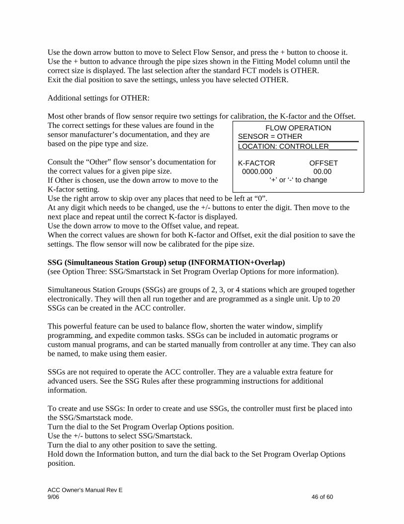
Use the down arrow button to move to Select Flow Sensor, and press the + button to choose it. Use the + button to advance through the pipe sizes shown in the Fitting Model column until the correct size is displayed. The last selection after the standard FCT models is OTHER. Exit the dial position to save the settings, unless you have selected OTHER. Additional settings for OTHER: Most other brands of flow sensor require two settings for calibration, the K-factor and the Offset. The correct settings for these values are found in the sensor manufacturer’s documentation, and they are based on the pipe type and size. Consult the “Other” flow sensor’s documentation for the correct values for a given pipe size. If Other is chosen, use the down arrow to move to the K-factor setting. Use the right arrow to skip over any places that need to be left at “0”.
FLOW OPERATION SENSOR = OTHER LOCATION: CONTROLLER_______ K-FACTOR OFFSET 0000.000 00.00
‘+’ or ‘-‘ to change
At any digit which needs to be changed, use the +/- buttons to enter the digit. Then move to the next place and repeat until the correct K-factor is displayed. Use the down arrow to move to the Offset value, and repeat. When the correct values are shown for both K-factor and Offset, exit the dial position to save the settings. The flow sensor will now be calibrated for the pipe size.
SSG (Simultaneous Station Group) setup (INFORMATION+Overlap) (see Option Three: SSG/Smartstack in Set Program Overlap Options for more information).
Simultaneous Station Groups (SSGs) are groups of 2, 3, or 4 stations which are grouped together electronically. They will then all run together and are programmed as a single unit. Up to 20 SSGs can be created in the ACC controller. This powerful feature can be used to balance flow, shorten the water window, simplify programming, and expedite common tasks. SSGs can be included in automatic programs or custom manual programs, and can be started manually from controller at any time. They can also be named, to make using them easier. SSGs are not required to operate the ACC controller. They are a valuable extra feature for advanced users. See the SSG Rules after these programming instructions for additional information. To create and use SSGs: In order to create and use SSGs, the controller must first be placed into the SSG/Smartstack mode. Turn the dial to the Set Program Overlap Options position. Use the +/- buttons to select SSG/Smartstack. Turn the dial to any other position to save the setting. Hold down the Information button, and turn the dial back to the Set Program Overlap Options position.
ACC Owner’s Manual Rev E 9/06 46 of 60

Release the Information button, and the SSG Setup screen will appear. The first possible SSG will be presented as STA GRP 01, and will display 4 rows (dashed lines in a new installation, station numbers if they have already been programmed). Each line is for a station that can become a member of the SSG.
SSG SETUP STA GRP 01
_ _ _ _ _ _ _ _ _ _ _ _ _ _ _ _ _ _ _ _ _ _ _ _ _ _ _ _ _ _ _ _ _ _ _ _ _ _ _ _
_____________________________
Use the down arrow to go to the first dashed line (or existing station number). Use the +/- buttons to select a station number. Once a station has been assigned to an SSG, it is no longer available for other SSGs, and will not appear as one of the choices while pressing + or – in other SSGs. Use the down arrow to go to the next station line, to add another station to the SSG. Include 2, 3, or 4 stations in the SSGs as needed. (It is possible to create an SSG of only 1 station, but this defeats the purpose of the SSG- single stations may be mixed in a program with SSGs, as long as they are not SSG members). When the SSG is complete, you can create another SSG without exiting the dial position. Use the up arrow to move back to the STA GRP location. Press +/- to select another STA GRP number. Continue to add stations and create SSGs until all desired groups are created and populated. Turn the dial to any other position to save. SSG Rules A station which is included in an SSG may still be started separately at the Manual Operation function or from the ICR remote control. A station which is included in an SSG is not available for individual placement in automatic Programs, while the controller is in SSG/SmartStack mode. In the Set Station Run Times position, individual stations which are SSG members will be shown, but their run times will show as *:**:** and cannot be changed. The display will show the number of the SSG to which they belong, and the run time for the SSG should be changed instead. SSGs are shown at the end of the station list when setting run times, and most other functions. For example, in a 12 station controller, the stations would be displayed as 1, 2, 3…12 followed by SSG 01, SSG 02, etc. Beginning from station 01, use the – button to see the SSGs quickly (like going backward from the beginning of the list to the end of the list). Edit an SSG Changing or deleting an existing SSG is done from the same Hidden Feature. Hold down the Information button, and turn the dial back to the Set Program Overlap Options position. Release the Information button to view the SSG Setup screen.
ACC Owner’s Manual Rev E 9/06 47 of 60

The first SSG will be displayed and highlighted. Change to a different SSG by pressing + or – to move through all SSGs. When the SSG to be edited is selected, use the down arrow to move to the stations area of the display. To replace a station in an SSG (with a different station): Highlight the station to be replaced. Press the + or – buttons to change the line to the new station number. To delete a station in an SSG (without replacement): Highlight the station to be replaced, and use the + or – buttons until the dashed line appears. This choice appears between the highest numbered station, and the lowest station remaining which has not been assigned to an SSG. Leave the dashed line and move to a different field in the display with the arrow buttons.
SSG SETUP SSG 01 – Front Grass
STA 01 – NW Turf STA 03 – NE Turf _ _ _ _ _ _ _ _ _ _ _ _ _ _ _ _ _ _ _ _
_____________________________
To add a station to an SSG: Use the down arrow to move to the next blank dashed line. Use the + or – to select the station to be added. Once all 4 lines are full (contain station numbers or names), the SSG is full and no more can be added. Adding an SSG Enter the SSG Setup mode (Information + Set Program Overlap Options). The first SSG will be highlighted. Use the + button to advance through all existing SSGs, until the next unused SSG appears (having all dashed lines with no station selections), and select stations as desired. Once the controller is in ACC Setup mode, all 20 SSGs are available, whether they are used or not. Deleting an SSG Technically SSGs are never deleted, as there are always 20 available. Instead, simply select the unwanted SSG, and delete the stations contained in it until no stations are listed under the SSG name. SSG Flow Data SSGs use the combined learned flow data for all their member stations. They do not have a flow assigned directly to them. If the stations in an SSG are edited (added or deleted), the flow for the whole SSG will change by the amount of that station. Custom Manual program setup (INFORMATION + Manual Operation) Custom Manual programs are “preset” irrigation sequences which do not run automatically, but can be started at any time from the Manual Operations position. The ACC permits up to 4 Custom Manual programs.
ACC Owner’s Manual Rev E 9/06 48 of 60

Custom Manual programs can be used for many specialized functions that are commonly started from the controller, to save tedious setup each time the function is needed. They also permit very flexible programming for unusual applications. To create a Custom Manual program: Press the Information button, and turn the dial the Manual Operations position. The Custom Manual setup screen will appear. The screen will show a setup form for Custom Manual Prg 01. To set up a different Custom Manual, press the Programs button to advance. To continue setting up the selected Custom Manual, press the down arrow to advance to the first Event. Events can be stations, SSGs, or even Delays. Events are the order in which items will run. Use the + or – button to choose a station or SSG for the first event. Use the right arrow to move to the duration (time) for the event. This can be completely different from any run times that item may have in regular programs (A-F). Use the down arrow to move to the next event, and continue until the Custom Manual program is complete. Custom Manual rules: Delays can be inserted as Events. Use the + or – buttons (the – button is often closer) to scroll through the stations and SSGs to DELAY (occurs below Station 01, and above the highest numbered station or SSG). Set a time for the delay as though it were a station. Stations and SSGs may be mixed in a Custom Manual. The same station (or SSG) may be included multiple times in a Custom Manual. Stations (or SSGs) may run in any order in Custom Manuals, unlike automatic programs. Custom Manuals are always run in an overlapping mode, because they are manually started. To start a Custom Manual:
• Turn the dial to the Manual Operation position. • Use the Program button to select the Custom Manual program (Custom Manual programs
will appear after the A through F selections). • Turn the dial to Run, to start the Program at the beginning. The display will show “To
Manually Start Station 01…”, but this only indicates that it will start at the beginning of the program. Each station will run for its programmed time (including Cycle and Soak settings), and stations with no run time in the selected program will be skipped.
• To start later in the Program (at a higher numbered station), use the down arrow to move to the station number, and press the +/- buttons to advance to the desired station (or SSG) number.
• Turn the dial back to Run to start the Program at the desired station. The Program will begin at that station and continue until the last event, then stop.
The display will show #-CUST under Mode, to show why the stations are running. Test Program: Programs button (hold) ACC has a quick Test program which will run all stations for a selectable period of time, in numerical order. The Test is an easy way to walk through every station in the system to verify
ACC Owner’s Manual Rev E 9/06 49 of 60

proper operation, or perform diagnostics. It also features a quick advance for stepping through stations with the arrow button. Test does not run SSGs or programs. It activates each individual station output in turn. To run a Test Program: Turn the dial to the Run position. Press and hold in the Programs button for approximately 3 seconds. The Test Program screen will appear below the time/date display. The screen will show Station 01 (and its name, if applicable) and the run time field will be highlighted. To start the Test Program on a station higher than 01, use the Up and Down arrow buttons to advance the starting station number. Use the +/- buttons to set the test run time, in mm:ss format. The maximum run time in Test mode is 15 minutes. Use the right and left arrow buttons to move between the minutes and seconds fields to set the universal test time, and then wait a few seconds. The Test program will begin running in 3 seconds if no further buttons are pressed. Each station will show the time remaining in the display. Once the Test program is running, the stations can be advanced or reversed without waiting for the run times to complete. Press the right arrow button to step up one station immediately. Press the left arrow button to back up one station (this will restart the previous station with a new Test run time).
4:15:13 PM THURSDAY 11/15/05
TEST PROGRAM Start with station: STA 01 – NW Turf Run each station: 00:00 (MM:SS)
WATERING AT 4:16:02 PM Sta Mode Time
01 TEST 0:00:58
Easy Retrieve™ backup (INFORMATION + Programs button at Run position) This saves the complete controller setup, including programs, start times, run times, etc., in a safe part of the controller’s memory. Once this info is saved, it can be recalled and the controller can be restored to that condition regardless of what has been programmed or altered since. Once the controller is running its basic programs and settings well after initial installation, this operation must be performed (otherwise, it cannot be recalled later). If other users alter the watering after installation or cannot remember what changes they have made, the Easy Retrieve function can be used to restore the controller to the original operating modes. To save an Easy Retrieve backup: First, make sure the controller is in the desired state of programming, including Days to Water, Start Times, Run Times, names, etc. Turn the dial to the Run position.
ACC Owner’s Manual Rev E 9/06 50 of 60

Press the Information and the Programs buttons at the same time. The Easy Retrieve save screen will appear. SAVE will be highlighted. Press the + button to save the program, and a confirmation message will appear. The Save can still be cancelled with the – button, or press + to complete the save. The backup will be complete if + is pressed.
EASY RETRIEVE SAVE
RESTORE Press + to
restore Easy Retrieve backup
To Restore an Easy Retrieve program: Turn the dial to the Run position. Press the Information and the Programs buttons at the same time, and the Easy Retrieve screen will appear. Use the down arrow button to move from Save to Restore. Press the + button to Restore. A confirmation message will appear. Press – to cancel the Restore, or + to continue with it. If + is pressed to confirm, the original saved Easy Retrieve program will replace the existing controller information. If you wish to make a new backup, leave Save highlighted and press + to create a new backup. This will completely replace the original Easy Retrieve backup with the new one. If no backup has ever been made, the Restore option will not be shown until an Easy Retrieve backup has first been saved. Manual Operations This dial position enables immediate operation of either a single station or an Automatic Program. It can also be used to start an SSG or a Custom Manual Program (if these optional items have been created).
MANUAL PROGRAM PROGRAM A
_____________________________TO MANUALLY START
STATION 01 0:00:00
TURN DIAL TO RUN
• Turn the dial to the Manual Operation position.
• Use the +/- buttons to switch between Manual Program, or Manual One Station.
“Program” will allow an entire Program to be run immediately, and will also allow the Program to be started at any station (to run from that point to the end). • Use the Program button to select the Program (Custom Manual programs will appear
after the A through F selections). • Turn the dial to Run, to start the Program at the beginning. The display will show “To
Manually Start Station 01…”, but this only indicates that it will start at the beginning of the program. Each station will run for its programmed time (including Cycle and Soak settings), and stations with no run time in the selected program will be skipped.
ACC Owner’s Manual Rev E 9/06 51 of 60

• To start later in the Program (at a higher numbered station), use the down arrow to move to the station number, and press the +/- buttons to advance to the desired station (or SSG) number.
• Turn the dial back to Run to start the Program at the desired station. The Program will begin at that station and continue until the last event, then stop.
Manually started Programs and Custom Manual programs do not run for multiple start times. Programs started at a higher station than their beginning station do not start over at the beginning… they run from the designated station and run to the end, then stop.
“Manual One Station” allows any individual station or SSG to be started. • Use the +/- keys to select a station. Any SSGs will appear at the end of the station list. • From the Station 01 position, the – button will go immediately to the highest numbered
station, or the SSGs. • Use the left and right arrow buttons to move between the hours:minutes:seconds fields. • Use the +/- buttons to set the desired run time in h:mm:ss format. • Turn the dial to the RUN position, and observe the display. The station or SSG will begin
irrigating within a few seconds. The display will always show a list of items running, why they are running, and the remaining time for each item. System Off To completely stop all irrigation, including any stations which are already running, turn the dial to the System Off position. Within a few seconds a large OFF will appear in the display. Any stations which were running will be shut down, and no new automatic irrigation will be allowed to start. It is also possible to set a programmable period (from 1 to 31 days) for Off, after which the system will automatically return to automatic irrigation. This is useful for halting irrigation when weather fronts or conditions are expected to persist for several days. To set a programmable Rain Off duration: turn the dial to the Off position. While the controller is in the OFF mode, press the + button and hold for approximately 3 seconds. The Days Left: xx display will appear. Release the + button, and then use the + or – button to set the desired number of Days Off before automatic irrigation will resume. Turn the dial back to Run immediately (the days off setting will time out if it is left more than 5-6 seconds). The display at the Run position will then show the number of days for the Off setting. This display will count down each day, showing the remaining days until automatic irrigation will resume.
ACC Owner’s Manual Rev E 9/06 52 of 60

Reset The ACC controller can be reset, erasing most programmed information. There are 5 different levels of Reset command available, but once any of them is chosen, the information will be permanently erased. These operations are not reversible! Reset should only be performed if:
a) a “clean start” is desired for programming purposes, or b) if directed to do so by Hunter Technical Services as a troubleshooting technique.
To Reset the ACC controller: Turn the dial to the Run position. RESET MEMORY
_____________________________Press and hold the Programs button, and at the same time press in the recessed Reset button with the tip of a ballpoint pen. Release the Reset button and continue holding the Programs button until the Reset Memory screen appears (then release the Programs button).
PROGRAMS FLOW TOTALS
LOGS NAMES
ALL DATA Press ‘+’ to select
The display will show the following Reset options: Programs: Erases Day schedules, start times, and run times. Flow Totals: Clears the running flow total histories (they will restart with 0.0 for all entries), only. Logs: Clears all alarm logs, only. Names: Clears all user-programmed names, including Programs, Stations, and SSGs. All Data: Clears all of the above items, and controller returns to original out-of-the-box programming state. Use the up and down arrows to highlight the desired type of Reset . Press the + button to select it. A confirmation message will appear. If + is pressed again, the selection will be reset. None of the reset functions will erase the Easy Retrieve™ “backup”, if one has been made. Decoder Operations (ACC99D versions) Connecting the 2-wire paths
2-wire path terminals (1-6)
Status LEDs
1. Turn Controller power OFF. 2. If the decoder output module is a replacement for an
existing decoder installation, simply reconnect the 2-wire paths to their screw terminal assignments. If more than one path has been used, attach the original red and blue pairs to the red and blue terminals with
Programming Port
ACC Owner’s Manual Rev E 9/06 53 of 60

the appropriate number. 3. If this is a new installation, or conversion of a conventional controller to decoder operations:
• Route the red and blue wire paths from the field up through the wire openings or conduit into the controller wiring compartment.
• Connect the red and blue 2-wire paths to the decoder output screw terminals. • There are two rows of screw terminals on the decoder output module, one red and one
blue, labeled 1-2-3-4-5-6. Each numbered pair represents a possible 2-wire path to the field (some systems only use one pair, others may use all 6).
• Connect the red wire from a twisted pair to a numbered red terminal, and connect the blue wire to the blue terminal with the same number. Do not connect more than one wire to any of the terminals. Do not mix red from one pair with the blue from another pair. Keep each pair separate, red to red and blue to blue, until all pairs are connected to their numbered terminals.
4. Turn controller power back ON and test. The Line Status LED on the decoder output module
should be a steady green, with no other line activity or stations running. The Module/Line Activity LED will again light for a few seconds.
The decoder output module should now be completely installed and ready for normal operations. Status Lights (ADM-99 Output Module) The ADM-99 decoder output module has four status LEDs which can be helpful with setup and diagnostics. The replacement upper deck label is used to label these lights.
Blank (Off): Normal. Solid Red: Problem in decoder output module Blinking Red: A decoder is faulted (possible solenoid short or damage), or a decoder fails to respond.
Red at power-up then goes out. Blinks Green when watering any station. Blinks Red, Overload or short on 2-wire path. Solid Red, problem in decoder output module.
Green when communicating down 2-wire path Amber when communicating through Programming Port
Green: Normal Blinking Green or Off: Problem in decoder output module.
Decoder Programming Each decoder is programmed with station address(es) at the controller, before installing it in the 2-wire path. The decoder output module has two holes in the lower right called “Programming Port”. Program the station number(s) into the decoders, and then write the station
ACC Owner’s Manual Rev E 9/06 54 of 60

number assignments on the metallic tag on the decoders. Overview of Decoder Programming
If any Decoder stations will be used for PUMP or Master Valve operation, you can also set their options first, before actually programming the decoders (this is recommended but not required). Unlock the Hidden Features at the Set Pump Operation dial position and select. See Special Decoders section for further information.
Then proceed to Decoder Operations at the Advanced Features dial position, described in detail in the next section.
If decoders will not be used for Pump activation, proceed directly to the Advanced Features dial position. Before programming any stations, you should have an exact plan on paper for the location of each decoder and station in the system. ICD decoders are available in 1, 2, 4, and 6-station sizes, and they may be mixed in the same system. However, the numbered station assignments for each decoder will be filled in automatically, depending on the size of the decoder. Do not program the same station number into two different decoders! When programming a 2, 4, or 6-station decoder, you only assign a station number to the first station output. The other stations are automatically filled in by the decoder in numerical order, depending on the decoder size. For example, a 4-station decoder (ICD-400) will activate stations 20, 21, 22, and 23. In programming, the decoder is assigned “20”. Because it is a 4-station decoder, it will automatically fill in the other stations with 21, 22, and 23. Single-station decoders (ICD-100) only receive the station number that is selected for them. DECODER FUNCTIONS
_____________________________Program a Decoder . . . . Press ‘+’ to select.
PROGRAM A DECODER _____________________________DEC TYPE: 1-STATION STATION NUMBER: 001 POWER FACTOR: 2 INRUSH: 5 Press PRG to send.
To Program Decoder Stations:
1. Turn controller power ON. 2. Insert the stripped end of the red wire from a
decoder into one of the two holes labeled Programming Port on the lower right of the decoder output module.
3. Insert the blue wire from the decoder into the other Programming Port hole. Do not let the wires touch each other!
4. Turn the controller dial to the Advanced Features position.
5. The display will show “DECODER FUNCTIONS”. Press the + button to select. (The other functions are
ACC Owner’s Manual Rev E 9/06 55 of 60

explained in detail in the Special Decoders section). 6. The Decoder Functions screen will appear, with “Program a Decoder” highlighted. Press
+ to select. The display will then show “Checking for a decoder…” as it attempts to communicate with the decoder in the Programming Port. The Communicating LED on the output module will light amber when the programming port is in use (communicating with a decoder).
7. The decoder output module will check for the presence of a decoder. If the wires are correctly inserted into the Programming Port, a screen will appear with the decoder settings.
8. If a decoder is recognized, the display will show current settings for the decoder. If the decoder is recognized as a station decoder, the size of the decoder (1, 2, 4 or 6) will show in the DEC TYPE area. Decoder type can be Station or Pump. Most decoders in most systems are type “Station”, which activate irrigation solenoids. • Use the up and down arrow buttons to highlight
different settings, and the + and – buttons to change them.
• Station number (When Dec Type is “Station”) can be any number from 001 to 099. Do not allow more than one decoder in a system to have the same station number!
PROGRAM A DECODER _____________________________DEC TYPE: PUMP P/MV: 1 POWER FACTOR: 2 INRUSH: 5 Press PRG to send.
• P/MV (When Dec Type is “Pump”) can be 1 or 2 (P/MV1 or P/MV2). Do not allow more than one decoder in a system to have the same pump number!
• Power Factor is normally 2 and this is correct for most installations. Possible range is 1 to 5. In certain situations it may be necessary to change this value to hold in heavier solenoid loads. These values will change the duty cycle of the power supplied to the decoder from 10 to 38% in approximately 7% increments. This value should not be adjusted unless absolutely necessary as it may adversely affect the performance of the rest of the system.
• Inrush is normally set to 5 and this is correct for most installations. Possible range is 1 to 9. These values will change the timing of the initial powering of the solenoid from 0 to 90mS in 10mS increments to aid in activating solenoids and relays with higher inrush current requirements.
9. When the decoder settings are correct, push the Program button to send them to the decoder. The display will show “Programming…” for a few seconds until the information is downloaded into the decoder.
10. If the programming (of the decoder) is successful, the display will show “PROGRAMMING COMPLETE” and prompt for another decoder. Using a ball point pen, write the station numbers for each output of the decoder on the aluminum label for later reference. If the decoder has been accidentally disconnected or malfunctions, the display will show “Programming Failed!”. This means the decoder was not programmed (check connection, and try again).
11. When all decoders and stations have been programmed, turn the dial to Run or any other position to continue working with the controller.
Decoders may be reprogrammed at any time. If it is necessary to change the station numbers or other settings of a previously programmed decoder, the decoder may be reconnected to the
ACC Owner’s Manual Rev E 9/06 56 of 60

Programming Port. The old settings will be displayed at the “Program a Decoder” screen. Change the settings and press Program to download the new station numbers or settings into the decoder. Decoder Pump/Master Valves Decoders can be assigned as either, or both, of the 2 possible Pump/Master Valve outputs per controller.
• Pump/Master Valve decoders should be ICD-100 single station decoders. If a multi-station decoder is assigned as a P/M, the other station outputs on that decoder are no longer available. It is possible to use the 200, 400, or 600 as a P/M output, but the other outputs will not function.
• The ACC or AGC controller only supports 2 Pump/Master Valve outputs, total, regardless of how they are connected. There are two “hardwired” output terminals on the controller’s Master Module (P/M1 and P/M2). Any combination of the Master Module terminals and the decoder stations is possible, but there can never be more than two P/M outputs, regardless of where they are connected.
To choose whether Pump/Master Valve outputs will be from the Controller or the Decoder, unlock the Hidden Feature by holding down the Information button on the facepack, while turning the dial to the Set Pump Operation position.
P/MV OPERATION _____________________________P/MV 1 STYLE: N.C. LOCATION: DECODER P/MV 2 STYLE: N.C. LOCATION: CONTROLLER
Release the button, to see the P/MV Operation screen. STYLE: “N.C.” means Normally Closed, which is the normal setting for most Master Valves (this works the same whether a Decoder is selected or not). It is not recommended to use the N.O. setting if the pump/master valve will be controller by a decoder. LOCATION: P/MV 1 and P/MV2 can each be set to either Controller (meaning the hardwired screw terminal position on the Master Module), or Decoder, if a decoder output module has been recognized by the facepack.
• The Decoder option is only shown if the ADM99 module has been installed and recognized by the controller.
“Controller” means the selected P/MV output will operate through the screw terminal with that number on the Master Module, in the controller. “DECODER” means that the selected P/MV will operate through one of the decoders instead. The specific decoder address is assigned in the Decoder Programming functions. .
• Use the Up and Down arrow buttons to move to the Location for the P/MV you wish to change.
• Use the + or – buttons to change the Location from Controller to Decoder, for any Pump/Master Valve you want to reassign.
ACC Owner’s Manual Rev E 9/06 57 of 60

The Decoder location will not work until a Decoder has been programmed for Pump operation (P/M1 or P/M2) in Decoder Programming (Advanced Features dial position). Troubleshooting Problem Causes Solutions No Display. Check AC~ power to controller.
Facepack is not firmly seated and locked, and/or 9-pin connector is not fully connected. Gray ribbon cable is connected from back of inner panel to cabinet.
Fix power supply. Seat facepack in connector. Connect ribbon cable on back of facepack door.
Display reads “Fault” (may be followed by Sensor number)
Sensor is activated. Overflow alarm has occurred (flow meter equipped controllers only).
Turn dial to Data History, select and review Alarm Log for individual alarm events.
Station does not irrigate. Field wiring or solenoid problem. Perform Manual One-Station start and observe display and output light. If light is red, check solenoid and field wiring, including COM (common) wires.
Controller does not irrigate automatically.
Possible programming errors. Sensor shutdown. Programmable Off in effect. Time/Date errors.
Verify all programs Days to Water, Start Times, and Station Run Times. Check display for Fault indication (if yes, press + for status). Check display for Off days. Verify controller time and date, including AM/PM/24 hour settings.
Rain or other Clik sensor does not shut down system.
Incorrect sensor type or connection. Incorrect sensor settings for Program.
Use one normally-closed Clik-type sensor per sensor port (SEN1-4). Verify that one wire from each sensor is to + and one to -. Do not connect multiple sensors to a single port. Turn dial to Set Sensor Operation and verify correct response for each program to the sensor (Pause or Shutdown).
Controller does not recognize output module (station size shown incorrect).
Module seated incorrectly. Module slot skipped. Station output module overloaded.
Verify that modules are seated all the way up in wiring compartment, and module lock is On. Verify that no module slots have been skipped, from left to right. Re-seat module, and observe green station light flashing when module is recognized. No station light, or red light: Swap with known-good module, check for green light. If new module works, replace old module (probably surge overload). If new known-good
ACC Owner’s Manual Rev E 9/06 58 of 60
module also fails to light, check gold and silver contacts for dirt, corrosion, pests.
AC~ fuse blows. Incorrect AC wiring. Surge on AC power line.
Verify that AC connections are correct for AC~ supply voltage. Check for lightning damage in vicinity.
Multiple output module failures.
Lightning. Modules not installed correctly. Overcurrent message.
Check and improve earth ground. Insure that modules are inserted correctly with ground contact in back, and pushed all the way up- red light should light momentarily when module is recognized. Too much current for station output (.56 Amp max). Divide solenoids over more station outputs.
Specifications Dimensions ACC1200 Cabinet : 123/8" H x 15½" W x 67/16" D (31.37 cm H x 39.37 cm W x 16.38 cm D) ACCPED Metal Pedestal: 361/8" H x 15½" W x 5" D (91.45 cm H x 39.37 cm W x 12.7 cm D) ACC1200PP Plastic Pedestal: 383/8" H x 219/16" W x 157/8" D (97.47 cm H x 54.61 cm W x 40.32 cm D) Electrical Transformer Input Supply wires must be 14AWG (1.85mm) or larger! 120/230VAC 50/60 Hz 1.2 A max at 120V/.73A max at 230V Transformer output: 24VAC, 4A, @ 120VAC Station output: .56A @ 24VAC Pump/Master Valve output: 325mA @24 VAC 24 VAC Test terminal output: 300mA @ 24 VAC Solenoid capacity: 2 standard 24 VAC Hunter solenoids per output, 14 solenoids max simultaneous (includes dual P/MV outputs). Battery, facepack: 9VDC alkaline, for facepack remote power only. Battery, facepack, internal: CR2032 lithium for real time clock only.
ACC Owner’s Manual Rev E 9/06 59 of 60

ACC Owner’s Manual Rev E 60 Hunter Industries Incorporated• The Irrigation Innovators 1940 Diamond Street • San Marcos, CA 92078 • TEL: 1 (760) 744-5240 • FAX: 1 (760) 744-7461 www.HunterIndustries.com
9/06