Embed Size (px)
DESCRIPTION
Academic portfolio based on BArch(hon) and Dip.Arch at Edinburgh College of Art.
Citation preview

ARCHITECTUREPORTFOLIO + CVYvonne Donaldson BArch (Hons), Dip.Arch

BOOK CITY/ Detailed Sectional Perspective
KEY
Retaining Wall:
Concrete Contiguous Piles / 400mmMembraneDrainage ChannelInsulation/ 100mm
Foundations/ Ground Floor:Foundations/ Ground Floor:
Concrete pilesConcrete Raft FoundationDamp Proof MembraneThermal Insulation/ 80mmScreed/ 80mmMortar Bed/ 15mmStone FloorStone Floor Tiles/ 15mm
Exterior Wall :
Concrete with polished finish/ 120mmCavity/ 30mmAirtight MembraneInsulation/ 120mmVapour Barrier sealed around window frameReinforced ConcreteReinforced Concrete / 250mm
Floor:
Concrete Ribbed Slab/ 250mmImpact sound insulation / 40mmSeparating Layer / 1mmScreed/ 80mmSlate tiles/ 15mm
Roof:Roof:
Plate-finish aluminium profile panelsThermal Insulation/ 100mmVapour BarrierAluminium trapezoidal sheeting/ 40mmPurlin, UPE section/ 160mmBeam, Parallel Flange Channel section/ 180mmMDF boardMDF board / 15mmPlasterboard/ 9mm
Balcony:
Okoume battens/ 40mmOkoume supporting battens/ 30mmFine Chippings, bonded Protective Fleece Thermal Insulation/ 80mmThermal Insulation/ 80mmCalendered Polymeric Roofing, two layersConcrete Ribbed slab, structural depth/ 300mm

BOOK CITY/ Model Development

BOOK CITY/ Floor Plans
Design Statement
“Within architecture, concept and context are inseparable. Frequently they also conflict. The concept may negate or ignore the circumstances that surround it, while the context may blur or dampen theprecision of an architectural idea.”Bernard Tschumi, 2004
Tschumi’s analysis of concept, context and content has influenced the way I approach design. For the Book City scheme I have contextualised a concept based on a cultural idea relating to literature.the Book City scheme I have contextualised a concept based on a cultural idea relating to literature.When an idea has been formed and then integrated with context and content it becomes aninterchangeable entity that is related to all three.
CONCEPT
My initial ideas for the project were related to literature and cultural ideas. I started the project by researching the development of literature from the Scottish Enlightenment, the philosophers, how it became a publishing centre and a early literate nation to become a city with an international profile. Scotland is defined by literature by many people who have not physically experienced the countrScotland is defined by literature by many people who have not physically experienced the country. The ideas of two contemporary authors interested me.
“I started writing novels as an undergraduate in an attempt to make sense of the city of Edinburghusing a detective as my protagonist. Each book hopefully adds another piece to the jigsaw that is modern Scotland, asking questions about the nations politics, economy, psyche and history...andperhaps pointing towards its possible future.”Ian Rankin
”Its the simplest and most magical thing to turn a page and be transported to a whole new world; see”Its the simplest and most magical thing to turn a page and be transported to a whole new world; seethings through someone else’s eyes.”JK Rowling
CONTEXT
The site is located at the bottom of the New Calton Burial Ground. It is surrounded by a 4m high wallsupported by buttresses at centres of 2.7m. My immediate reaction when I visited the site was that I wanted to reconnect to the surroundings and see out over the wall. There are spectacular views fromthe north side of the burial ground at its highest point. the north side of the burial ground at its highest point. The Palace of Holyrood House , the Scottish Parliament and the Salisbury Crags are visible. From the site itself there are views up to the watchtower , Burns Monument and the Nelson Monument on Calton Hill. The design intent was to reconnect to these views with a tower. I also chose this part of the site in order to connect with the end of the Royal Mile. In terms of the wider context the centre will be expected to form a relationshipwith the existing literary quarter in Edinburgh which is loosely based around the spine of the Royal Mile. Mile. Although this is not the closest point geographically it is where the anticipated flow of people would come from. Due to the public nature of the building and the promotion of Scottish Literature I thought it was appropriate to create a strong street presence.
CONTENT
The accommodation is stacked vertically, wrapped around a core that contains stairs, a lift and toilets.The private office areas for the City of Literature and the Edinburgh International Book Festival are sandwiched between the public areas. The book shop and the box office are on the bottom floor withthe exhibition space overlooking the double height reception area. the exhibition space overlooking the double height reception area. The core has been pushed out over the wall with a polycarbonate facade to screen the neighboring buildings. The top floors contain the writers’ booths and the cafe. The cafe is the focal point of the project. It cantilevers outconnecting to the visual axis created by the views
CAFE/ 6
WRITING/ 5
CITY OF LIT/ 4
FESTIVAL/ 3
OFFICE/ 2
EXHIBITION/ 1
BOOK SHOP BOX OFFICE/ 0

BOOK CITY/ Long Section

BOOK CITY/ 3D Visualisations
Entrance/ Exhibition Office Cafe

ARCHITECTURE + DESIGN SCOTLAND/ Plans and Section
Section B-B Section C-C
Ground Floor First Floor Second Floor Third Floor

ARCHITECTURE + DESIGN SCOTLAND/ Model Development

ARCHITECTURE + DESIGN SCOTLAND, BAKEHOUSE CLOSE/ 3D Visualisations

ARCHITECTURE + DESIGN SCOTLAND/ Detailed Section 1:50Lift Shaft Wall:
Flat sided pre-patinated copper tilesTimber boards/ 15mmReinforced concrete blockwork/ 180mmDamp proof membraneKingspan rigid insulation/ 50mmMdf boards/ 12mmMdf boards/ 12mm
Lift Shaft Roof:
Reinforced concrete ring beam/ 250mm x 180mmTimber wallplate/ 50mm x 50mmSteel gutterLead flashing/ Grade 2/ 50mmMdf boards/ 12mmKingspan insulation/ 80mmKingspan insulation/ 80mmTimber rafters/ 100mmTimber sarking/ 20mmDamp proof membraneFlat sided pre-patinated copper tiles
Lift Car/ 1500mm x 1400mm
Glass Entrance: Prefabricated glass panel bolted to Prefabricated glass panel bolted to wall using steel angle
Rooftop Exhibition Space:
Floor:
Steel Structural Hollow SectionsWide Flange Beams/ 200mmSteel profile trapezoidal floor/ 100mmConcrete filling/ 50mmConcrete filling/ 50mmInsulation/ 100mmDamp proof membraneBattens/ 30mm x 50mmReclaimed teak flooring/ 24mm
Facade:
Aluminium facade sections/ 2300mm x 1500mm2300mm x 1500mmDouble glazing, inner pane of laminated safety glass
Roof:
Standard steel section/ 200mmPlasterboard/ 12mmSteel Profile trapezoidal floor/ 50mmInsulation/ 100mmDamp proof membraneDamp proof membraneTimber sarking board/ 20mmFlat sided unpatinated copper cladding
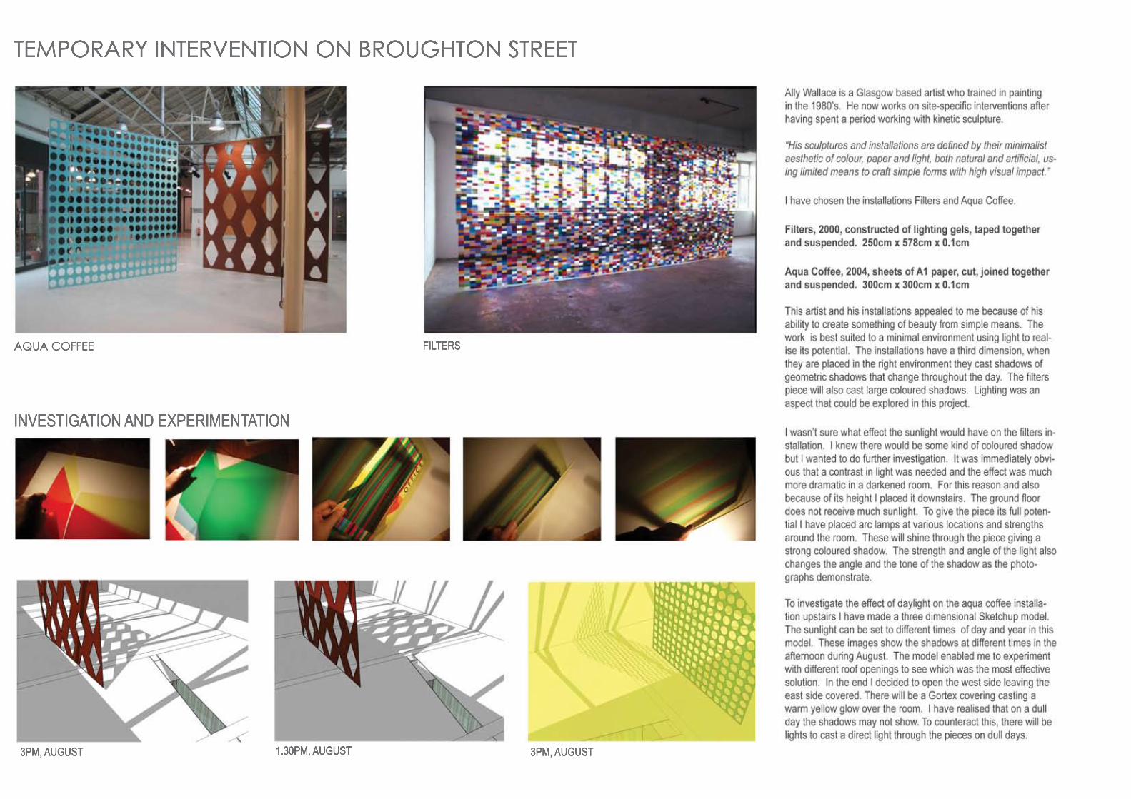
TEMPORARY INTERVENTION ON BROUGHTON STREET
3PM, AUGUST
INVESTIGATION AND EXPERIMENTATION
1.30PM, AUGUST3PM, AUGUST
AQUA COFFEE FILTERS

TEMPORARY INTERVENTION ON BROUGHTON STREET/ Context and Connections
SITE LOCATION PLAN 1:2000
SITE LAYOUT PLAN 1:500
The site is in the Edinburgh New Town. It is situated in ahidden pocket surrounded by tenement buildings. The views out of the site are restricted by the perimeter of buildings. Access to the site itself is down a lane, so isalso quite restricted.
Due to this constraining context, visual connections became important in this scheme. Neighbouring became important in this scheme. Neighbouring volunteers could tack brightly coloured paper to their window frames or shutters so the exhibition could extend beyond the site. This idea can work in the opposite direction as well, the opened roof structurecould expose the exhibition and when it is lit up at nightit acts as a beacon in the neighbourhood.
The purple lines on the site plan demonstrates the visual connections between the exhibition and the adjacent buildings. Since the buildings are going to be demolished I thought it would be fun to paint some of the surfaces around the building to give a link to the colours and geometry of the artworkand geometry of the artwork

TEMPORARY INTERVENTION ON BROUGHTON STREET/ Construction
CONCEPT - SHIFTING PERSPECTIVES
The overall idea was to make only minimal change in terms of structure and expense to maximise the potential of the space for the artist.
The Filters piece will sit at a diagonal on the ground floor, the idea is that in the morning the natural light will shine through it creating a vibrant coloured shadow on the floor. The natural light in this area is limited so when this is not adequate, additional artificial light will shine direct light to enhance the shadow.Arc lamps that have been inserted in the void between the double skinned wall will illuminate the piece at night. This should have quite a dramatic effect. I have placed it at a diagonal in the room to catch the morning sun when it is at its strongest.have placed it at a diagonal in the room to catch the morning sun when it is at its strongest.
There will be a strip removed where the existing windows are. No additional structure will be required. This is to bring in even daylight for viewing and to takeaway the claustrophobic sense of space that exists on the ground floor. There will be mirrored paper tacked between the floor joists to give another dimensionto the viewing of the piece. All of the surfaces in the room will be painted white apart from the floor joists. The paint should be applied directly onto the surfaceof the wall to maintain the existing texture.
I decided to place theI decided to place the Aqua Coffee pieces on the first floor because of their height and because they don’t require a specific quality of light. I have covered the roof on the eastern side so the light is more directed. The installations should cast shadows of geometric shapes across the white painted floor. The exposed structure is covered by clear film tacked to the timber and by carbon fibre rods and gortex on the outside. The pieces can be hung using fishing bait wire and hooks screwed into the structure.
ROOF PLAN
FIRST FLOOR PLAN
AXONOMETRIC OF SLICE THROUGH STRUCTURE
GROUND FLOOR PLAN
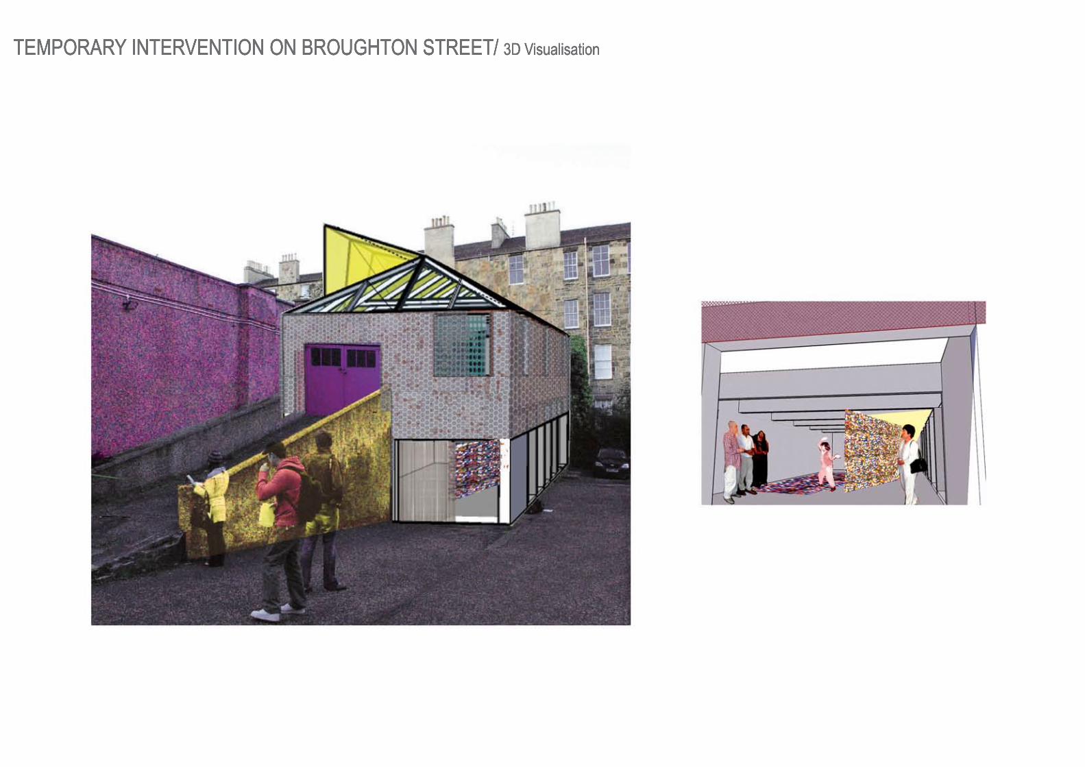
TEMPORARY INTERVENTION ON BROUGHTON STREET/ 3D Visualisation

Centre for Asylum Seekers and Refugees/ Urban Strategy
CONTOURS CANAL
STRETCHED CITYPOPULATION

Centre for Asylum Seekers and Refugees/ Urban Strategy
SIGHTHILL AREA
PORT DUNDAS AREA OF GLASGOW
MOTORWAY
RAILWAY LINE
CLOSE PROXIMITY TO CITY CENTRE
INDUSTRIAL AREA PROPOSED TOW
ER BLOCK SPEIRS W
HARF REGENERATION

CENTRE FOR ASYLUM SEEKERS AND REFUGEES/ 3D Visualisation

CENTRE FOR ASYLUM SEEKERS AND REFUGEES/ Ground Floor Plan 1:500 N
01 Accommodation1 Disabled Access2 Two Bedroom/ Study3 Three Bedroom4 Extended Family5 Studio Flat
0202 Generic Teaching Learning Spaces6 Mini Library7 Computer Suite8 Teaching Space
03 Specialised Facilities9 Market1010 Trading Stall11 Barge Unloading12 Trading Administration13 Market Square14 Cafe15 Kitchen16 Store1717 Staff18 Laundry19 Disposal20 Dining21 Exterior Dining22 Medical Centre23 Reception2424 Waiting25 GP26 Nurse27 Dispensary28 Nursery29 Office30 Reception3131 Laundry32 Kitchen33 Wash34 Open Play Space35 Store36 Quiet Room37 Store/ Maintenance3838 Exterior Play39 Employment Centre40 Reception41 Waiting42 Electronic Job Finder43 Advice44 Finance4545 Meeting Room
04 Live Video Link, MP’s and Local Councillors Suites
46 Conference Room47 Meeting Room

CENTRE FOR ASYLUM SEEKERS AND REFUGEES/ Investigation and exploration through model making

CENTRE FOR ASYLUM SEEKERS AND REFUGEES/ Education and Employment Centre/ Section
KEY:
CURVED THREE PIN TRUSS
01 Structured sealant glazing/ 12mm02 Aluminium mullions / 200mm03 Arched three pin truss Top member/ 100mm Bottom member/ 200mm Strutts/ 75mm04 Diagonal bracing05 Sheet zinc rainwater gutter06 Steel awning bolted to truss and supported by steel tension cable07 End of truss attached to a steel plate and bolted to concrete foundations
WALL/ OPENING
08 Corrugated metal sheeting, galvanised09 Ventilated cavity (vertical sheeting)/ <40mm10 Thermal insulation (cellulose fibres)/ 50mm11 Thermal insulation in steel sheet trays/ 80mm12 Timber windows with integral louvre blind1313 Trimmer14 Rainwater drip (sheet metal)15 Damp proof course
FLOOR
16 Precast slab resting on pile foundations/ 300mm17 Damp proof membrane1818 Cellulose fibre thermal insulation/ 60mm19 Flooring
ROOF
20 Cellular glass insulation21 Protective waterproofing22 Separating and protective layer23 Chippings/ 60mm2424 Concrete flags/ 500mm x 500mm

Detail of three pin arched truss with an awning:1 Inner section of truss, 200mm dia2 Circular steel section purlins, 80mm dia3 Aluminium mullion supporting laminated safety glass4 Steel awning welded to truss5 Steel wire tension cable66 Zinc rainwater gutter
1
1 5 6
7
8 9
13 12
11
10
2 3 4
2 3 4 4
5
6
Detail of the junction between terrace and facade1 Concrete flags, 500 x 500mm2 Chippings, 60mm3 Protective layer4 Cellular glass insulation, 140mm5 Reinforced conrete topping, 60mm66 Trapezoidal metal profile7 Steel safety barrier8 Aluminium corrugated metal sheeting9 Ventiled cavity10 Thermal insulation, 130mm11 Metal ties12 Sqare hollow section, 300mm1313 Universal beam, 305 x 165mm, bolted
CENTRE FOR ASYLUM SEEKERS AND REFUGEES/ Construction Details 1:20

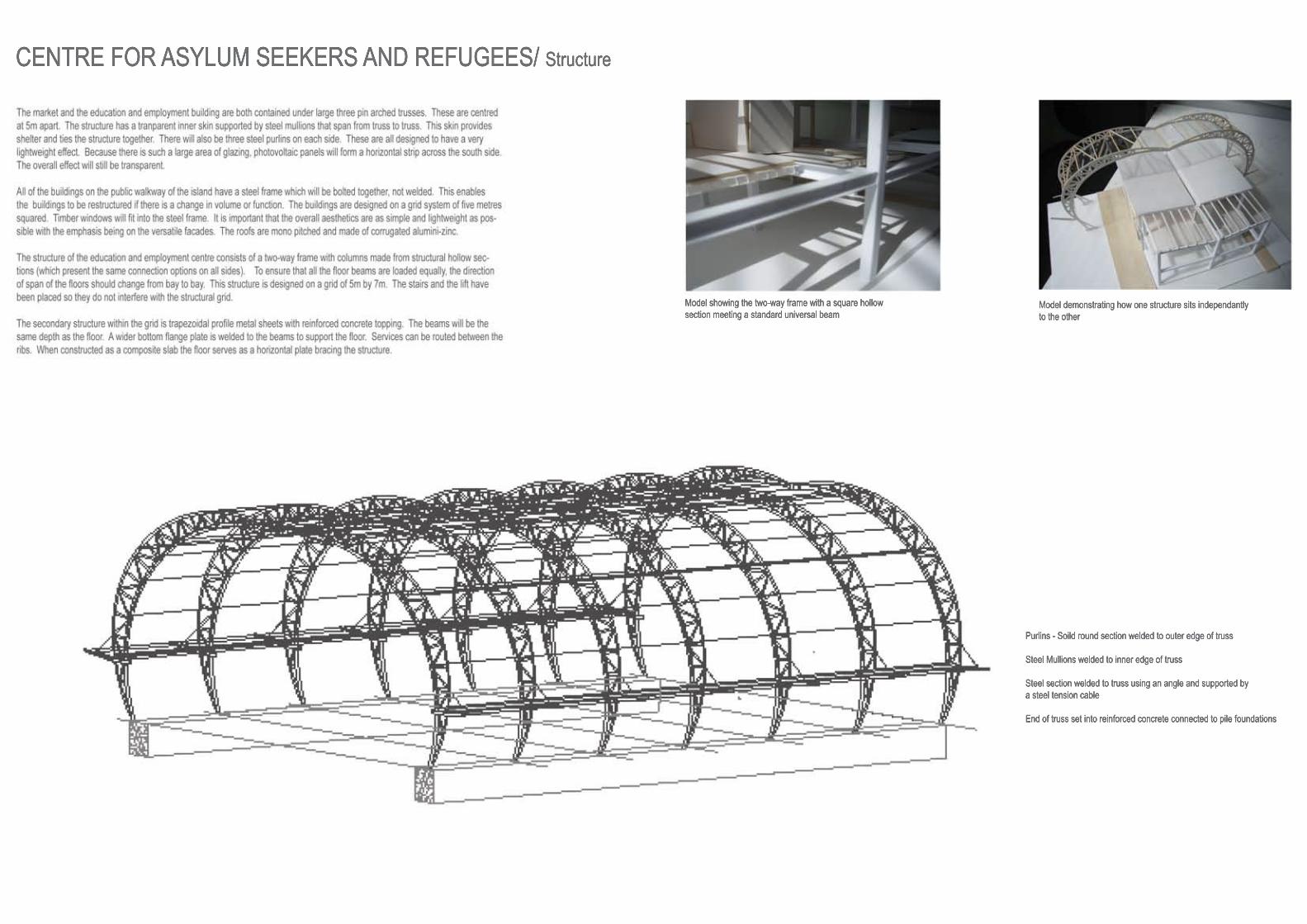
CENTRE FOR ASYLUM SEEKERS AND REFUGEES/ Structure
The accommodation is arranged on a 5 metre squared grid along the edge of the island. The houses are designed within a double plot space of one hundred square metres and are mostly two storeys. They are designed as prefabricated units which will be assembled elsewhere in a factory environment,transported to site by lorry and then craned into position. Each unit is raised off the ground on four parallel steel trusses (350mm deep). I have raised theunits off the ground to create a boundary between public and private space within a confined area. The structure of the unit itself consists of timber and steel. steel. The walls and floors are made up of a platform timber structure with 200 x 50mm floor joists at 550mm centres and 200 x 50mm timber columns. Within this structure and directly attached to the grid of steel below are steel hollow sections with hooks at the top. This means that the houses can be at a later stage of construction because the steel supports the timber structure when the whole unit is being lifted.
On the supporting grid below the units steel square hollow sections are bolded to the trusses in a in a perpendicular direction at centres of 1000mm. The steel columns that run between the timber columns are also attached directly to the steel grid. steel columns that run between the timber columns are also attached directly to the steel grid. Theses are also 80mm steel square hollow sections. Thesesit between the steel columns at centres of 500mm. The floor joists run perpendicular to the steel hollow sections. The first floor and the roof are supported by timber joists which are supported by the platform frame. The houses can be transported in two sections and then assembled together on site. This typeof design makes the units much more flexible in size, use and location.
The houses rest on ground that is very close to the edge of the part of the canal that has been recently constructed. The houses rest on ground that is very close to the edge of the part of the canal that has been recently constructed. This means that the infill that has beenused will not have settled properly. To ensure that the houses will rest evenly on the surface when the ground sinks, the trusses will be supported by solid reinforced concrete slabs that rest on pile foundations that have been driven into the ground
CENTRE FOR ASYLUM SEEKERS AND REFUGEES/ Structure
Model demonstrating how one structure sits independantly to the other
Purlins - Soild round section welded to outer edge of truss
Steel Mullions welded to inner edge of truss
Steel section welded to truss using an angle and supported by a steel tension cable
End of truss set into reinforced concrete connected to pile foundations
Model showing the two-way frame with a square hollowsection meeting a standard universal beam

CRAIGMILLAR PRIMARY SCHOOL +
Ground Floor Plan
First Floor Plan
Key:01 Entrance02 Primary 203 Primary 304 Primary 405 Primary 50606 Primary 607 Primary 708 Communal Space09 Tutorial Space10 Library11 Maintenance1212 Storage13 Administration14 Reception15 Dining16 Kitchen17 Staff18 Plant1919 Laundry/ Store20 Office21 Nursery22 Open Plan Administration23 Principle24 Deputy2525 Business26 Resource27 Staffroom
CRAIGMILLAR PRIMARY SCHOOL +
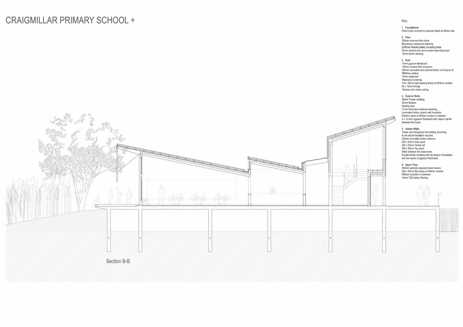
Section B-B
Key:
1 FoundationsPiled in-situ concrete to required depth at 300mm dia
2 Floor300mm concrete floor slabsBituminous waterproof sheeting2x30mm foamed plastic insulating slabs2x30mm foamed plastic insulating slabs50mm cement and sand screed separating layer19mm timber decking
3 Roof15mm gypsum fibreboard140mm mineral fibre insulation300mm laminated and twinned timber roof beams at3500mm centres3500mm centres19mm chipboardWaterproof underlay120 x 60mm load bearing timber at 625mm centres60 x 12mm firringsTitanium zinc sheet roofing
4 Exterior Walls20mm20mm Timber cladding30mm BattensSealing layer21mm laminated softwood sheetingLaminated timber column with insulationPartition studs at 600mm centres in between2 x 12.5mm gypsum fibreboard with vapour barrier between the layersbetween the layers
5 Interior WallsThese vary throughout the building according to the sound insulation required200mm laminated timber columns200 x 50mm Sole piece200 x 20mm Timber sill200 x 50mm200 x 50mm Top pieceWalls between the classrooms:Double timber studding with two layers of insulationand two layers of gypsum fibreboard.
6 Upper Floor300mm partially exposed timber beams200 x 50mm floor joists at 400mm centres 200mm insulation in between200mm insulation in between19mm T&G timber flooring