Embed Size (px)
Citation preview
AC VOLTAGE RATIO MEASUREMENT
HENRY P, HALL, General Radio Company
w HE3 RESISTANCE, mass, length, etc., are measured in term of standards kept by national
Iaboratories, voltage ratio, being dimensionless, has no national, legal standard. Thus anyone may make ratio measurements and may claim my accuracy he feels he can justify, even if it exceeds that claimed by a national laboratory.
At reasonable frequencies and voltages (e.g., 1 kTJq 100 v) , avaihble ratio-measuring systems have sensitivities on the order of one part-per-Won (ppb) of input; comparisons on voltage dividers can be re peated to this accuracy on successive measurements, With two dividers (one reversed with mpect to the other), the comclion for the 0.5 point cctn ,be re peatedly determined to within a few ppb.
One way to evaluate the aocuracy of voltage ratio measurements is to compare results obtained using several different techniques. Many methods have been used for this measurement. Several use precision resis- tors, but at 100 v and 1 kHz, low value resistor^ dhi- pate excessive power and therefore cbange, while high value resistors exhibit excessive phase W. Thus these methods were avoided.
' Three alternative methods were selected: the cyclic capacitor method of Cutkosky and Shields (Ref. I ) , the bootstrap method of Sze (Ref. 2) and Hill (Ref.
3), and a straddling method based on the common re- versing technique.
Cyelie Capacitor Method In this technique, a decade transformer is com-
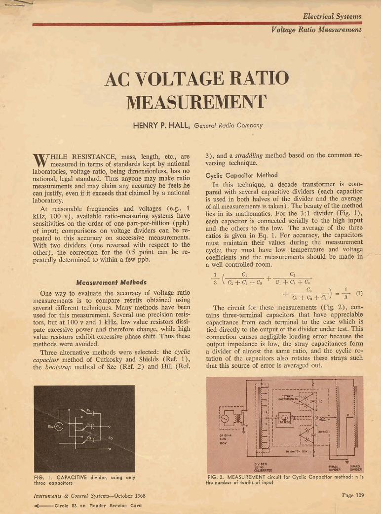
pared with several capacitive dividers (each capacitor is used in both halves of the divider and the average of all measurements is taken). The beauty of the method lies in its mathematics. For the 3 : 1 divider (Fig. 1 ), each capacitor is connected serially to the high input and tbe others to the low. The average of the three ratios is given in Eq. 1, For accuracy, the capacitors must nzahtain their values during the measurtmcnt cycIe; they must have: low tempeathue and voltage coefficients and the measurements should be made in.-/ - - a well controlled room.
The circuit for these measurements (Fig. 2) , con- tains threeterminal capacitors that have appreciable capacitance from each terminal to the case which i8 tied directly to the output of the divider under test. This connection causes negligible loading e m because the output impedance is low, the stray capacitances form a divider of almost the same ratio, and rhe cyclic m tation of the capacitors also rotates thae strays su& that this source of error is averaged out.
F16. I. CAPAClTtVE divider, using only F I ~ . 2, MEASUREMENT C f w H for Cydie C a p a c h ~ mothod; n Is
4-.CtrcIe 8Z on Reader Servtce Card
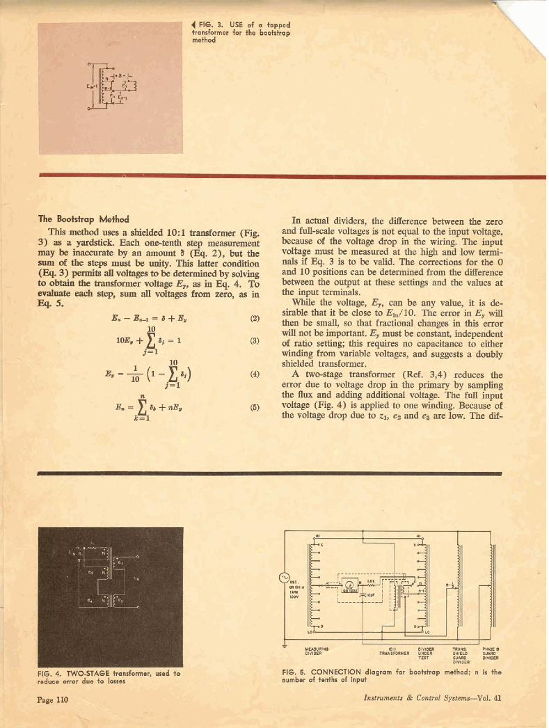
The BooMrap M & d This method uses a shie.lded 10: 1 transformer (Fig.
3) as a ymhtick Each -tenth step measuremmt may be hccurate by an srmount 1 (Eq. 2), but the sam of the step mast be unity. This latter condition (Eq. 3) parnits all voltages to be determined by solving to obtain the transformer voltage E,, m in Eq. 4. To ~ t d ~ & p , s a m a l l d ~ h m z e r o , s u r i n I3q. 5.
In actual dividers, the mexence between the zero and full-scale voltages is not equal to the input voltage, because of the voltage drop in the wiring. The input voltage must be measured at the hihigh and low tenti- d s if Eq. 3 is to be valid. The corrections for the 0 and 10 positions cm be determined from the difference between the output at thae settings and the value8 at the input terminah. While the voltage, E,, can be any valuey it is de-
sirable that it be dose to E d l O . The error in E, will then be small, rn that fractional c h w in this error will not be important. E, must be constant, independent of ratio setting; this r e q h no capacitance to either winding from variable voltages, and mggats a doubly shielded tmsformer.
A two-stage t rdofmer (Ref. 3,4) reduces the ermr due to voltage drop in the primary by sampfing the flux and adding additional voltage. The frill input voltage (Fii 4) is applied to one winding. Because of the voltage drop due to zb e~ and e8 are low. The dif-
Fl6. 8. CONNECTIOH diagram for bootrfrap mdhod; n is the number of tonths of Input
ferenoe between ei. and q is applied to a m n d trans- 30 ppb. Multiple runs, made by the bootstrap meth former whose output is added to q as a correction. all fell within this spread, as did the 0.5 point deter- Such -age transformers wifh errm of lw than mined by h p l e reversal. 20 ppb of input are not difEult to find. With the boot- An NBS calibration, which states lt.200 ppb &'. strap mdhd (Fig. 5 ) , m-mements and calcuIatiom curacy, differed by a maximum of 50 ppb from the for all 1/10 s q s a n be made in one hour, measured average. The repeataliility of the r d t s de
scribed here suggests that the average of the measlu The Straddling Mefhod ments is within 20 ppb of true value,
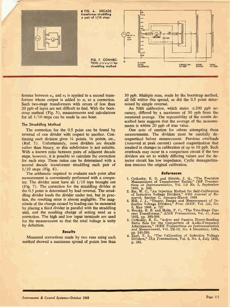
The correction for the 0.5 point can be found by One note of caution for others atkmpting thew reversal of one divider with respect to another. Con- measurements. The dividers must be carefully de- tine such division gives % points, 341 points, etc., magnetized before measurement. Previous o v d d (Ref. 5 ) . Unfortunately, most dividers are decade (removed at peak canmi) caused magnetization that rather tban binary, so this subdivision is not suitabIe. resulted in changes in calibration of up to 10 ppb. Such With a known ratio between pairs of adjacent decade overiods may occur in a comparison circuit if the two
I stepst, however, it is p i b l e to calculate the amredon dividers are set to widely di&hg values and the ds for m& step. Thm ratios can be determined with a tector circuit ha^ low impedance. Cyclic demaguetiza- m u d decade t c a d m e r stmddbg each pair of tim restores the original calibration. 1/10 step (Pig. 6 ) - The arithmetic required to evaluate each point after References
measurement is c01 lvh t ly performed with a compu- 1. Cutkoaky, R. D. and Shields, J. Q., "The Precision ter. The divider must have all 1/10 taps brought out Measurement of Tra+ormer Ratios,'' IRE Tm- (Fig. 7). The correction for the straddling divider at ihm~ on I ~ h w w n ~ , Vol. 1-9 No. 2, September
the 0.5 point i s determined by lead reversal. The s t d - ,, izOId.. 245.
C., -An Injection Method for Self-Cdibratlm dlhg divider loads the divider under test, but in pmc- of fnductive Vol*ge- Dividsrn" NBS Jm-i of Re-
#&, hiection C, danuary-darch 1988 ti% mulag e m -f mdWle. The mag- % ~ m , J. J., u ~ ~ e o ~ , ~ev and ~eanurment o f I.- nitude of the change caused by hading csin be m e a s d ductive Voltage Dividere, PTOC. IEEE, Vol. 115, No.
5, May 11988, p. 727 'Y plaoinp a third in parallel L Brook, & B. .nd Holb F. C,, -Sws. Qlw # unit, and the resulting change of setting used as a rent Tranltfomrc A I E ~ Tm~~dawtbw, Vol. 41, June correction. The high and low input terminah are wed 1022, g ~ . 882-895. for Ulc meamemeat so that the total voltage is unity 6* Cut$sp R. D., L a A ~ t i ~ e and Pasaive Direct-Reding by dehition. Itst10 eta for the Cornpanson of Audio-Frequency
Admittances," IEHE Tramme* 0% I ~ s e t m w t m t a t h a d M~a.au~$?n#tt, Vol. 1-M-13, No. 4 December, 1904,
Resulfs 243-260.
Measured om made by two runs using each 6. T. L, "The Calibration of Inductive Volts ~ividen:' I$A T - W W Vol. 2, No. 3, July 19&
method &owed a maximum spread of points h than g. 196.
Page 111