Embed Size (px)
Citation preview

U.S. Department of Transportation Federal Aviation Administration
Advisory Circular
Subject: Approval Guidance for RNP Procedures with AR
Date: 2/23/11
Initiated by: AFS-400
AC No: 90-101A
Change: 1. PURPOSE. This advisory circular (AC) provides airworthiness and operational approval guidance material for aircraft operators conducting Title 14 of the Code of Federal Regulations (14 CFR) part 97 Area Navigation (RNAV) Required Navigation Performance (RNP) instrument approach procedures (IAP) with Authorization Required (AR), charted as “RNAV (RNP) RWY XX.” Hereafter, refer to these procedures as “RNP AR” within this AC. Operational approvals obtained under the guidelines of this AC also apply to existing RNAV (RNP) IAP with special aircraft and aircrew authorization required (SAAAR). As current RNAV (RNP) SAAAR instrument approach charts are revised or amended, they will be updated to reflect AR.
a. Method of Compliance. This AC provides a method of compliance with public RNP AR IAP requirements. In lieu of following this method without deviation, operators may elect to follow an alternative method, provided the alternative method is acceptable to the Federal Aviation Administration (FAA).
b. Language. This AC uses mandatory terms such as “must” only in the sense of ensuring applicability of these particular methods of compliance when using the acceptable means of compliance described herein. This AC does not change, add, or delete regulatory requirements or authorize deviations from regulatory requirements.
2. DEFINITIONS.
a. Area Navigation (RNAV). A method of navigation, which permits aircraft operation on any desired flightpath within the coverage of ground- or space-based Navigational Aids (NAVAID), within the limits of the capability of self-contained aids, or a combination of these.
b. Estimate of Position Uncertainty (EPU). A measure based on a defined scale in nautical miles (NM), which conveys the current position estimation performance, also known as Actual Navigation Performance (ANP) and Estimate of Position Error (EPE) in certain aircraft. The EPU is not an estimate of the actual error, but a defined statistical indication.
c. Flight Management System (FMS). An integrated system, consisting of airborne sensor, receiver, and computer with both navigation and aircraft performance databases, which provides performance and RNAV guidance to a display and automatic flight control system (AFCS).
d. Global Positioning System (GPS). GPS is a U.S. satellite-based radio navigation system that provides a positioning service anywhere in the world. The definition of the service provided by GPS for civil use is in the GPS Standard Positioning System (SPS) Signal Specification. GPS

AC 90-101A 2/23/11
Page 2 Par 2
is the U.S. core Global Navigation Satellite System (GNSS) satellite constellation providing space-based positioning, velocity, and time. GPS is composed of space, control, and user elements.
e. Global Navigation Satellite System (GNSS). GNSS is a generic term for a worldwide position, velocity, and time determination system, which includes one or more satellite constellations, aircraft receivers, and system integrity monitoring. GNSS includes GPS, Satellite-Based Augmentation Systems (SBAS) such as the Wide Area Augmentation System (WAAS), Ground-Based Augmentation Systems (GBAS) such as the Local Area Augmentation System (LAAS), Global Orbiting Navigation Satellite System (GLONASS), GALILEO, and any other satellite navigation system approved for civil use. GNSS can be augmented as necessary to support the RNP for the actual phase of operation.
f. Primary Optimum Field of View (FOV). For the purpose of this AC, the primary optimum FOV is within 15 degrees of the pilot’s primary line of sight.
g. Radius to a Fix (RF) Leg. An RF leg is defined as a constant radius circular path, around a defined turn center, that starts and terminates at a fix. An RF leg may be published as part of a procedure.
h. Receiver Autonomous Integrity Monitoring (RAIM). An algorithm that verifies the integrity of the position output using GPS measurements or GPS measurements and barometric aiding.
i. Required Navigation Performance (RNP). RNP is a statement of the 95 percent navigation accuracy performance that meets a specified value for a particular phase of flight or flight segment and incorporates associated onboard performance-monitoring and alerting features to notify the pilot when the RNP for a particular phase or segment of a flight is not being met.
j. Required Navigation Performance (RNP) Value. The RNP value designates the lateral performance requirement in NM increments associated with a procedure. Examples of RNP values are RNP 0.3 and RNP 0.15.
3. RELATED READING MATERIAL (current editions).
a. Where You Can Find ACs/Orders/Notices. You can find this AC at http://www.faa.gov/regulations_policies/advisory_circulars and Orders/Notices at https://employees.faa.gov/tools_resources/orders_notices. Inspectors can also access this AC through the Flight Standards Information Management System (FSIMS) at http://fsims.avs.faa.gov (see the link to http://rgl.faa.gov). Operators and the public may find this information at http://fsims.faa.gov (see the link to http://rgl.faa.gov).
(1) Order 8400.12, Required Navigation Performance 10 (RNP 10) Operational Authorization;
(2) Order 8260.52, United States Standard for Required Navigation Performance (RNP) Approach Procedures with Special Aircraft and Aircrew Authorization Required (SAAAR);

2/23/11 AC 90-101A
(3) AC 20-138, Airworthiness Approval of Positioning and Navigation Systems;
(4) AC 20-153, Acceptance of Data Processes and Associated Navigation Databases;
(5) AC 25.1309-1, System Design and Analysis;
(6) AC 25-15, Approval of Flight Management Systems in Transport Category Airplanes;
(7) AC 120-29, Criteria for Approval of Category I and Category II Weather Minima for Approach; and
(8) AC 120-91, Airport Obstacle Analysis.
b. RTCA, Inc., Documents. Obtain copies of the following RTCA documents from RTCA, Inc., 1828 L Street, NW, Suite 805, Washington, DC 20036, or purchased online at http://www.rtca.org:
(1) RTCA/DO-178B, Software Considerations in Airborne Systems and Equipment Certification;
(2) RTCA/DO-187, Minimum Operational Performance Standards for Airborne Area Navigation Equipment Using Multi-Sensor Inputs;
(3) RTCA/DO-189, Minimum Operational Performance Standards for Airborne Distance Measuring Equipment (DME) Operating within the Radio Frequency Range of 960-1215 MHz;
(4) RTCA/DO-200A, Standards for Processing Aeronautical Data;
(5) RTCA/DO-201A, Standards for Aeronautical Information;
(6) RTCA/DO-208, Minimum Operational Performance Standards for Airborne Supplemental Navigation Equipment Using Global Positioning System (GPS);
(7) RTCA/DO-229D, Minimum Operational Performance Standards for Global Positioning System/Wide Area Augmentation System Airborne Equipment;
(8) RTCA/DO-236B, Minimum Aviation System Performance Standards: Required Navigation Performance for Area Navigation; and
(9) RTCA/DO-283A, Minimum Operational Performance Standards for Required Navigation Performance for Area Navigation.
c. FAA Technical Standard Orders (TSO). Obtain copies of the following TSOs from the U.S. Department of Transportation, Publications Department, Ardmore East Business Center, 3341Q 75th Avenue, Landover, MD 20785:
(1) TSO-C115b, Airborne Area Navigation Equipment Using Multi-Sensor Inputs;
Par 3 Page 3

AC 90-101A 2/23/11
Page 4 Par 3
(2) TSO-C129a, Airborne Supplemental Navigation Equipment Using the Global Positioning System (GPS);
(3) TSO-C145c, Airborne Navigation Sensors Using the Global Positioning System (GPS) Augmented by the Satellite Based Augmentation System; and
(4) TSO-C146c, Stand-Alone Airborne Navigation Equipment Using the Global Positioning System Augmented By The Satellite Based Augmentation System.
4. BACKGROUND. RNP AR approaches provide an unprecedented level of flexibility in construction of approach procedures. These operations are RNAV procedures with a specified level of performance and capability. RNP AR approach procedures build upon the performance-based National Airspace System (NAS) concept. When RNP approaches replace visual or Nonprecision Approaches (NPA) safety is enhanced and efficiency improves through more repeatable and optimum flightpaths. A predefined aircraft capability and navigation system are the basis for conventional obstacle evaluation areas for ground-based NAVAIDs. The RNP AR criteria design is flexible in order to adapt to unique operational requirements, which can include avoiding terrain or obstacles, de-conflicting airspace, or resolving environmental constraints. This allows for approach-specific performance requirements.
a. AR. RNP AR approaches include unique capabilities that require special aircraft and aircrew authorization similar to Category (CAT) II/III instrument landing system (ILS) operations. All RNP AR approaches have reduced lateral obstacle evaluation areas and vertical obstacle clearance surfaces predicated on the aircraft and aircrew performance requirements of this AC. In addition, selected procedures may require the capability to fly an RF leg and/or a missed approach, which requires RNP less than 1.0. Appendix 2 of this AC identifies specific aircraft requirements that apply to these capabilities.
b. Navigation Performance Monitoring. A critical component of RNP is the ability of the aircraft navigation system to monitor its achieved performance and to identify for the pilot whether the performance meets set standards during an operation.
5. APPROVAL.
a. Overview. Operators may receive operational approval to conduct RNP AR IAPs through operations specifications (OpSpecs), management specifications (MSpecs), or letters of authorization (LOA), as appropriate to the operator. Operators should comply with the requirements in Appendices 2 through 6. Appendix 7 describes information operators should submit when seeking approval for RNP AR operations. It contains a checklist to use as a guide in preparing the application, as well as an approval process flowchart. Prior to application, operators and manufacturers should review all performance requirements. Installation of equipment by itself does not guarantee final approval for use.
NOTE: Operational approvals issued under the guidance of AC 90-101 also apply to RNP AR approach procedures.
b. Aircraft Qualification and Initial Acceptance of Recommended Operational Documentation.

2/23/11 AC 90-101A
(1) Aircraft Qualification Documentation. Aircraft manufacturers should develop aircraft qualification documentation showing compliance with Appendix 2. This documentation identifies the optional capabilities (e.g., RF legs and RNP missed approaches), the RNP capability of each aircraft configuration, and the navigation system characteristics that may require operational mitigations to meet the requirements of this AC. This documentation should also define the recommended RNP maintenance procedures.
(2) RNP AR Operational Documentation. Aircraft manufacturers are strongly encouraged to develop RNP AR operational documentation. This documentation would provide operators of their aircraft with recommended procedures/practices for: Navigation Database (NDB) validation, flying RNP AR instrument approaches, pilot/dispatcher RNP AR training, and an RNP monitoring program, all in accordance with the requirements of Appendices 3 through 6 of this AC. The operator’s use of manufacturer-developed and FAA-accepted operational documentation would likely facilitate the operational approval process.
(3) FAA Acceptance.
(a) For new aircraft, approval of the aircraft qualification documentation can be part of an aircraft certification project and reflected in the Aircraft Flight Manual (AFM) and related documents. The Aircraft Evaluation Group (AEG) may also receive the RNP AR operational documentation and coordinate with the Flight Technologies and Procedures Division (AFS-400) for final acceptance.
(b) For existing aircraft, the aircraft manufacturer should submit the aircraft qualification and RNP AR operational documentation to AFS-400. AFS-400 will coordinate with other FAA offices and may accept the package as appropriate for RNP AR operations. AFS-400 will document acceptance in a letter to the aircraft manufacturer.
c. Operator Approval. Title 14 CFR part 91, 91 subpart K (part 91K), 121, 125, or 135 operators should provide their Flight Standards District Office (FSDO)/certificate-holding district office (CHDO) with the information listed in Appendix 7, reflecting compliance with the requirements of Appendices 2 through 6. Aircraft qualification and operational documentation provided by the aircraft manufacturer and accepted by the FAA will facilitate the operator’s preparation of the items listed in Appendix 7. The FSDO/CHDO will coordinate with FAA headquarters (HQ) in accordance with Appendix 7, Figure 2, RNP AR Application Flow. Once the operator has satisfied the requirements of this AC, or equivalent, the FSDO/CHDO issues OpSpecs, MSpecs, or an LOA authorizing RNP AR approach procedures.
(1) Interim Authorization. Ordinarily, operators will have authorization to conduct RNP AR approaches using minima associated with RNP 0.3, for a period of 90 days and until the operator has accumulated 100 AR approaches in each aircraft type. For approach procedures with no line of minima associated with RNP 0.3, you must fly the procedure in visual meteorological conditions (VMC).
NOTE: Operators experienced with equivalent RNP approaches may receive credit toward the interim authorization requirements.
NOTE: Experienced RNP AR operators operating new or upgraded aircraft types/systems, derivative types, or different aircraft types with identical crew
Par 5 Page 5

AC 90-101A 2/23/11
interface and procedures may use reduced interim authorization periods (e.g., less than 90 days and 100 approaches) as determined by the CHDO/FSDO.
NOTE: In unique situations where the completion of 100 successful approaches could take operators an unreasonably long period of time due to factors such as a small number of aircraft in the fleet, limited opportunity to use runways having appropriate procedures, etc., consideration of a reduction in the required number of approaches will be on a case-by-case basis. The FSDO/CHDO will coordinate with FAA HQ in consideration of an operator’s request for reduced interim authorization requirements.
(2) Final Authorization. The CHDO/FSDO will issue OpSpecs, MSpecs, or LOA authorizing use of lowest applicable minima after operators satisfactorily complete their interim authorization period and upon the CHDO/FSDO review of reports from the operator’s RNP monitoring program.
(3) Aircraft Modification. If any aircraft system required for RNP AR is modified (e.g., software or hardware change/revision), the operator must obtain the manufacturers’ updated aircraft qualification and operational documentation confirming continued suitability for RNP AR approach operations. AFS-400 and either AFS-200 or AFS-800, must approve the operator’s use of the aircraft with modifications for RNP AR operations. The FSDO/CHDO should coordinate with AFS-470 to facilitate processing of the operator’s request for operational approval with the changed/revised equipment.
/s/ for John M. Allen Director, Flight Standards Service
Page 6 Par 5
2/23/11 AC 90-101A Appendix 1
APPENDIX 1. RNP AR IAPs
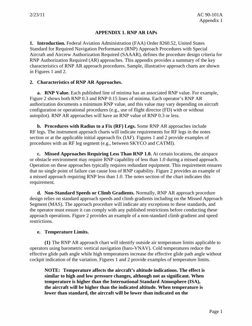
1. Introduction. Federal Aviation Administration (FAA) Order 8260.52, United States Standard for Required Navigation Performance (RNP) Approach Procedures with Special Aircraft and Aircrew Authorization Required (SAAAR), defines the procedure design criteria for RNP Authorization Required (AR) approaches. This appendix provides a summary of the key characteristics of RNP AR approach procedures. Sample, illustrative approach charts are shown in Figures 1 and 2.
2. Characteristics of RNP AR Approaches.
a. RNP Value. Each published line of minima has an associated RNP value. For example, Figure 2 shows both RNP 0.3 and RNP 0.15 lines of minima. Each operator’s RNP AR authorization documents a minimum RNP value, and this value may vary depending on aircraft configuration or operational procedures (e.g., use of flight director (FD) with or without autopilot). RNP AR approaches will have an RNP value of RNP 0.3 or less.
b. Procedures with Radius to a Fix (RF) Legs. Some RNP AR approaches include RF legs. The instrument approach charts will indicate requirements for RF legs in the notes section or at the applicable initial approach fix (IAF). Figures 1 and 2 provide examples of procedures with an RF leg segment (e.g., between SKYCO and CATMI).
c. Missed Approaches Requiring Less Than RNP 1.0. At certain locations, the airspace or obstacle environment may require RNP capability of less than 1.0 during a missed approach. Operation on these approaches typically requires redundant equipment. This requirement ensures that no single point of failure can cause loss of RNP capability. Figure 2 provides an example of a missed approach requiring RNP less than 1.0. The notes section of the chart indicates this requirement.
d. Non-Standard Speeds or Climb Gradients. Normally, RNP AR approach procedure design relies on standard approach speeds and climb gradients including on the Missed Approach Segment (MAS). The approach procedure will indicate any exceptions to these standards, and the operator must ensure it can comply with any published restrictions before conducting these approach operations. Figure 2 provides an example of a non-standard climb gradient and speed restrictions.
e. Temperature Limits.
(1) The RNP AR approach chart will identify outside air temperature limits applicable to operators using barometric vertical navigation (baro-VNAV). Cold temperatures reduce the effective glide path angle while high temperatures increase the effective glide path angle without cockpit indication of the variation. Figures 1 and 2 provide examples of temperature limits.
NOTE: Temperature affects the aircraft’s altitude indications. The effect is similar to high and low pressure changes, although not as significant. When temperature is higher than the International Standard Atmosphere (ISA), the aircraft will be higher than the indicated altitude. When temperature is lower than standard, the aircraft will be lower than indicated on the
Page 1

AC 90-101A 2/23/11 Appendix 1
Page 2
altimeter. For additional information, refer to the Altimeter Errors paragraph in chapter 7 of the Aeronautical Information Manual (AIM).
(2) Operators using baro-VNAV in an aircraft with an airworthiness approval for automatic temperature compensation, or in an aircraft using an alternate means for vertical guidance (e.g., Satellite-Based Augmentation Systems (SBAS)), may disregard the temperature limits (high temperature limit still applies if the system only compensates for low temperature).
f. Aircraft Size. Aircraft size may determine the minimums for an RNP AR approach procedure. Large aircraft may require higher minimums due to gear height and/or wingspan. Approach charts will annotate any applicable aircraft size restrictions when appropriate. Figure 1 provides an example of an aircraft size restriction.

2/23/11 AC 90-101A Appendix 1 FIGURE 1. EXAMPLE OF RNP AR APPROACH PROCEDURES WITH A RADIUS TO
A FIX LEG SEGMENT
Page 3
AC 90-101A 2/23/11 Appendix 1
Page 4
FIGURE 2. EXAMPLE OF RNP AR APPROACH PROCEDURES WITH A RADIUS TO A FIX LEG SEGMENT WITH A MISSED APPROACH REQUIRING RNP
LESS THAN 1.0

2/23/11 AC 90-101A Appendix 2
APPENDIX 2. AIRCRAFT QUALIFICATION
1. Introduction. This appendix describes the performance and functional criteria for aircraft to qualify for RNP AR approaches. Applicants may establish compliance with this appendix as part of a type certification or Supplemental Type Certification (STC) and document this in the Aircraft Flight Manual Supplement (AFMS). The type-certificate holder of a previously certified aircraft can document compliance with these aircraft qualification criteria without a new airworthiness project (e.g., without an Aircraft Flight Manual (AFM) change), and should advise the appropriate Aircraft Certification Office (ACO) of any new performance not covered by the original airworthiness approval. The AFM or other aircraft qualification evidence should address: the required modes of operation to fly an RNP AR approach, the normal and abnormal flightcrew operating procedures, responses to failure alerts and annunciations, and any other operating limitations. In addition to the specific RNP AR guidance in this document, the aircraft must comply with the current edition of AC 20-138, Airworthiness Approval of Positioning and Navigation Systems.
2. Performance Requirements. This paragraph defines the general performance requirements for aircraft qualification. Paragraphs 3, 4, and 5 provide guidance material on an acceptable means of satisfying these requirements.
a. Path Definition. The published instrument approach procedure (IAP) and section 3.2 of RTCA/DO-236B define the path the aircraft must use to evaluate performance. The aircraft’s navigation system will also define all vertical paths in the Final Approach Segment (FAS) by a Flight Path Angle (FPA) (RTCA/DO-236B, Section 3.2.8.4.3) as a trajectory to a fix and altitude.
b. Lateral Accuracy. The aircraft must comply with section 2.1.1 of RTCA/DO-236B.
c. Vertical Accuracy. The vertical system error includes altimetry system error (assuming the temperature and lapse rates of the International Standard Atmosphere (ISA)), the effect of along-track error, system computation error, data resolution error, and Flight Technical Error (FTE). The 99.7 percent of system error in the vertical direction must be less than the following (in feet):
( )( )( ) ( ) ( )( ) ( )( )( )22 2 22 8 36076115 1 225 60 75 88 10 65 10 50. . tan tan . .RNP h h h hθ θ Δ Δ− −⋅ + + + − ⋅ + + ⋅ + +
NOTE: Where θ is the vertical navigation (VNAV) path angle, h is the height of the local altimetry reporting station and Δh is the height of the aircraft above the reporting station.
d. Airspace Containment. The FAA publishes RNP AR approaches as performance-based approaches. As such, they do not inherently require any specific technology or procedure but instead require a level of performance.
(1) Primary Means of Compliance. This AC provides a detailed acceptable means of compliance for aircraft using an Area Navigation (RNAV) system relying primarily on Global
Page 1

AC 90-101A 2/23/11 Appendix 2 Navigation Satellite System (GNSS) and a VNAV system relying on barometric altimetry or Satellite-Based Augmentation Systems (SBAS). Paragraphs 3, 4, and 5, in conjunction with guidance described in Appendices 3 and 4, describe an acceptable means of achieving the required navigation performance. Aircraft and operations complying with these paragraphs provide the requisite airspace containment.
(2) Other Systems or Alternative Means of Compliance (AMOC). For other systems or AMOC, the probability of the aircraft exiting the lateral and vertical extent of the obstacle clearance volume (see FAA Order 8260.52, United States Standard for Required Navigation Performance (RNP) Approach Procedures with Special Aircraft and Aircrew Authorization Required (SAAAR)), must not exceed 10-7 per approach, including the missed approach. An operator may satisfy this requirement through an operational safety assessment applying: appropriate quantitative, numerical methods; qualitative operational and procedural considerations and mitigations; or an appropriate combination of both quantitative and qualitative methods.
NOTE: If the aircraft does not remain within the obstacle clearance volume after annunciating the system’s failure, then this requirement applies to the total probability of excursion outside the obstacle clearance volume. This includes events caused by latent conditions (integrity) and by detected conditions (continuity). When ensuring the aircraft does not exit the obstacle clearance volume, an analysis of the aircraft performance should consider the monitor limit of the alert, the latency of the alert, the crew reaction time, and any aircraft response to the alert. The requirement applies to a single approach, considering the exposure time of the operation and the Navigational Aid (NAVAID) geometry and navigation performance available for each published approach.
NOTE: This containment requirement derives from the operational requirement. This requirement is notably different from the containment requirement specified in RTCA/DO-236B. The requirement in RTCA/DO-236B facilitates airspace design and does not directly equate to obstacle clearance.
e. System Monitoring. The critical components of RNP AR approach procedure implementation are the RNP requirements of the approach and the ability of the aircraft navigation system to both monitor navigation performance and alert the pilot when RNP requirements are not being met.
3. RNP AR General Requirements.
NOTE: RTCA/DO-236B provides additional information concerning many of the required functions for RNP AR aircraft qualification.
a. Position Estimation. The navigation system must estimate the aircraft’s position. This section identifies unique issues for the navigation sensors within the context of RNP AR instrument approaches.
Page 2

2/23/11 AC 90-101A Appendix 2
(1) GNSS.
(a) The GNSS sensor must comply with the guidelines in AC 20-138. The total system accuracy analysis may use the following sensor accuracies without additional substantiation: GNSS sensor accuracy better than 36 meters (95 percent), and augmented GNSS (Ground-Based Augmentation Systems (GBAS) or SBAS) sensor accuracy is better than 2 meters (95 percent).
(b) In the event of a latent GNSS satellite failure and marginal GNSS satellite geometry (e.g., horizontal integrity limit (HIL) equal to the horizontal alert limit), the probability the total system error remains within the procedure design obstacle clearance volume must be greater than 95 percent (both laterally and vertically).
NOTE: GNSS-based sensors output an HIL, also known as a horizontal protection level (HPL) (refer to AC 20-138 appendix 1 and RTCA/DO-229C for an explanation of these terms). HIL is a measure of the position estimation error assuming a latent failure is present. In lieu of a detailed analysis of the effects of latent failures on the total system error, an AMOC for GNSS-based systems is to ensure HIL remains less than twice the RNP value, minus the FTE 95 percent, during the RNP AR approach operation.
(2) Inertial Reference Unit (IRU). An IRU must satisfy the criteria of Title 14 of the Code of Federal Regulations (14 CFR) part 121 appendix G. While appendix G defines the requirement for a drift rate of 2 nautical miles (NM) per hour for flights up to 10 hours, this rate does not apply to an RNAV system after loss of position updating. A manufacturer may assume an IRU demonstrating compliance with part 121 appendix G experiences an initial drift rate of 4 NMs for the first 30 minutes (95 percent) without further substantiation. Aircraft manufacturers and applicants can demonstrate improved inertial performance in accordance with the methods described in Appendix 1 or 2 of FAA Order 8400.12, Required Navigation Performance 10 (RNP-10) Operational Approval.
NOTE: Integrated GNSS/IRU position solutions reduce the rate of degradation after loss of position updating. For “tightly coupled” GNSS/IRUs, RTCA/DO-229C, appendix R, provides additional guidance.
(3) Distance Measuring Equipment (DME). GNSS-updating is the basis for initiating all RNP AR approach procedures. The aircraft may use DME/DME-updating as a reversionary navigation mode during an RNP AR approach or missed approach when the navigation system continues to comply with the required RNP value. The manufacturer should also identify any requirements for the DME infrastructure and/or any necessary operational procedures and limitations for conduct of an RNP AR approach procedure through the use of DME/DME-updating of the aircraft’s position.
(4) Very High Frequency (VHF) Omni-Directional Range Station (VOR). The aircraft’s RNAV system may not use VOR-updating during public RNP AR IAPs. The
Page 3

AC 90-101A 2/23/11 Appendix 2
Page 4
manufacturer should identify any flightcrew procedures or techniques for a given aircraft to comply with this requirement.
NOTE: The aircraft need not have a direct means of inhibiting VOR updating. The operator may meet the requirement of this paragraph by providing operational procedures enabling flightcrews to inhibit VOR-updating or procedures requiring a missed approach upon annunciation of reversion to VOR-updating.
(5) Multi-Sensor Systems. There must be automatic reversion to an alternate RNAV sensor if the primary RNAV sensor fails. However, there need not be automatic reversion from one multi-sensor system to another multi-sensor system.
(6) Altimetry System Error. The 99.7 percent aircraft altimetry system error for each aircraft (assuming the temperature and lapse rates of the ISA) must be less than or equal to the following with the aircraft in the approach configuration:
8 2 388 10 65 10 50. .ASE H H− −= − ⋅ ⋅ + ⋅ ⋅ + (ft) (where H is the true altitude of the aircraft)
(7) Temperature Compensation Systems. Temperature compensation systems with an airworthiness approval providing corrections to the baro-VNAV guidance must comply with RTCA/DO-236B, appendix H.2. This requirement applies to the final approach segment. Manufacturers should document compliance to this standard to allow the operator to conduct RNP AR approaches when the actual temperature exceeds the temperature limits published on the RNP AR approach chart.
b. Path Definition and Flight Planning.
(1) Maintaining Track and Leg Transitions. The aircraft must have the capability to execute leg transitions and maintain tracks consistent with the following paths:
(a) A geodesic line between two fixes;
(b) A direct path to a fix;
(c) A specified track to a fix, defined by a course; and
(d) A specified track to an altitude.
NOTE: You can find the industry standards for these paths in RTCA/DO-236B and ARINC Specification 424, which refer to them as TF, DF, CF, and FA path terminators. Also, certain procedures require RF legs as described in paragraph 4 of this appendix. EUROCAE ED-75A, RTCA/DO-236B and ED-77/DO-201A describe the application of these paths in more detail.

2/23/11 AC 90-101A Appendix 2
NOTE: The navigation system may accommodate other ARINC 424 path terminators (e.g., VM) and the missed approach procedure may use these types of paths when there is no requirement for RNP containment.
(2) Fly-By and Fly-Over Turns. The aircraft must have the capability to execute fly-by and fly-over turns. For fly-by turns, the navigation system must limit the path definition within the theoretical transition area defined in RTCA/DO-236B under the wind conditions identified in FAA Order 8260.52. Since the fly-over turn is not compatible with RNP flight tracks, RNP AR procedure design will use a fly-over turn at a fix only when there is no requirement for RNP containment.
(3) Waypoint Resolution Error. The navigation database (NDB) must provide sufficient data resolution to ensure the navigation system achieves the required accuracy. Waypoint resolution error must be less than or equal to 60 feet, including both the data storage resolution and the RNAV system computational resolution used internally for construction of flight plan waypoints. The NDB must contain vertical angles (FPAs) stored to a resolution of hundredths of a degree, with computational resolution such that the system-defined path is within 5 feet of the published path.
(4) Capability for a “Direct-To” Function. The navigation system must have a “Direct-To” function the flightcrew can activate at any time. This function must be available to any fix. The system must also be capable of generating a geodesic path to the designated “To” fix, without “S-turning” and without undue delay.
NOTE: The manufacturer should identify any limitations associated with the operational use of the aircraft navigation system’s “Direct-To” function. For example, if there are limitations associated with intercepting an RF leg segment, the AFM or aircraft qualification guidance should identify those limitations.
(5) Capability to Define a VPATH. The navigation system must be capable of defining a vertical path by a FPA to a fix. The system must also be capable of specifying a vertical path between altitude constraints at two fixes in the flight plan. The navigation system must also define fixed altitude constraints as one of the following:
(a) An “AT or ABOVE” altitude constraint (for example, 2400A may be appropriate for situations where bounding the vertical path is not a requirement);
(b) An “AT or BELOW” altitude constraint (for example, 4800B may be appropriate for situations where bounding the vertical path is not a requirement);
(c) An “AT” altitude constraint (for example, 5200); or
(d) A “WINDOW” constraint (for example, 2400A3400B).
(6) Altitudes and/or Speeds. The navigation system must extract from the onboard NDB the altitudes and/or speeds defined in published terminal procedures.
Page 5

AC 90-101A 2/23/11 Appendix 2
(7) Path Construction. The navigation system must be able to construct a path to provide guidance from current position to a vertically constrained fix.
(8) Capability to Load Procedures from the NDB. The navigation system must have the capability to load the entire flight procedure into the RNAV system from the onboard NDB. This includes the approach (including vertical angle), the missed approach, and the approach transitions for the selected airport and runway.
(9) Means to Retrieve and Display Navigation Data. The navigation system must provide the means for the flightcrew to verify the flight procedure through review of the data stored in the onboard NDB. This includes the ability to review the data for individual waypoints and for NAVAIDs.
(10) Magnetic Variation. For paths defined by a course (CF and FA path terminators), the navigation system must use the magnetic variation value for the procedure in the NDB.
(11) Changes in RNP Value. Changes to lower RNP values must be complete by the first fix defining the leg with the lower value. The manufacturer must identify any operational procedures necessary to meet this requirement.
NOTE: One acceptable means to meet this requirement may be manually setting the lowest RNP value contained within the RNP AR procedure, prior to commencing the approach.
(12) Automatic Leg Sequencing. The navigation system must provide the capability to automatically sequence to the next leg and display the sequencing to the flightcrew in a readily visible manner.
(13) Altitude Restrictions. A display of the altitude restrictions associated with flight plan fixes must be available to the pilot. The equipment must display the FPA associated with any flight plan leg of an RNP AR procedure.
c. Demonstration of Path Steering Performance. When a demonstration of RNP capability includes a demonstration of the aircraft’s path steering performance (i.e., FTE), you must conduct that demonstration in accordance with AC 120-29, paragraphs 5.19.2.2 and 5.19.3.1.
d. Displays.
(1) Continuous Display of Deviation. The navigation system must provide the capability to continuously display to the pilot flying, on the primary flight instruments for navigation of the aircraft, the aircraft position relative to the RNAV defined path (both lateral and vertical deviation). The display must allow the pilot to readily distinguish if the cross-track deviation exceeds the RNP value (or a smaller value) or if the vertical deviation exceeds 75 feet (or a smaller value).
(a) The aircraft should have an appropriately-scaled, non-numeric deviation display (i.e., lateral deviation indicator and vertical deviation indicator) in the pilot’s primary optimum
Page 6
2/23/11 AC 90-101A Appendix 2
Page 7
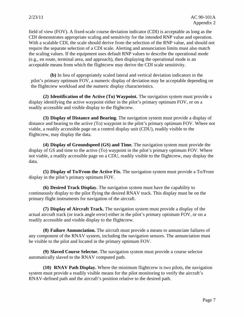
field of view (FOV). A fixed-scale course deviation indicator (CDI) is acceptable as long as the CDI demonstrates appropriate scaling and sensitivity for the intended RNP value and operation. With a scalable CDI, the scale should derive from the selection of the RNP value, and should not require the separate selection of a CDI scale. Alerting and annunciation limits must also match the scaling values. If the equipment uses default RNP values to describe the operational mode (e.g., en route, terminal area, and approach), then displaying the operational mode is an acceptable means from which the flightcrew may derive the CDI scale sensitivity.
(b) In lieu of appropriately scaled lateral and vertical deviation indicators in the pilot’s primary optimum FOV, a numeric display of deviation may be acceptable depending on the flightcrew workload and the numeric display characteristics.
(2) Identification of the Active (To) Waypoint. The navigation system must provide a display identifying the active waypoint either in the pilot’s primary optimum FOV, or on a readily accessible and visible display to the flightcrew.
(3) Display of Distance and Bearing. The navigation system must provide a display of distance and bearing to the active (To) waypoint in the pilot’s primary optimum FOV. Where not viable, a readily accessible page on a control display unit (CDU), readily visible to the flightcrew, may display the data.
(4) Display of Groundspeed (GS) and Time. The navigation system must provide the display of GS and time to the active (To) waypoint in the pilot’s primary optimum FOV. Where not viable, a readily accessible page on a CDU, readily visible to the flightcrew, may display the data.
(5) Display of To/From the Active Fix. The navigation system must provide a To/From display in the pilot’s primary optimum FOV.
(6) Desired Track Display. The navigation system must have the capability to continuously display to the pilot flying the desired RNAV track. This display must be on the primary flight instruments for navigation of the aircraft.
(7) Display of Aircraft Track. The navigation system must provide a display of the actual aircraft track (or track angle error) either in the pilot’s primary optimum FOV, or on a readily accessible and visible display to the flightcrew.
(8) Failure Annunciation. The aircraft must provide a means to annunciate failures of any component of the RNAV system, including the navigation sensors. The annunciation must be visible to the pilot and located in the primary optimum FOV.
(9) Slaved Course Selector. The navigation system must provide a course selector automatically slaved to the RNAV computed path.
(10) RNAV Path Display. Where the minimum flightcrew is two pilots, the navigation system must provide a readily visible means for the pilot monitoring to verify the aircraft’s RNAV-defined path and the aircraft’s position relative to the desired path.

AC 90-101A 2/23/11 Appendix 2
(11) Display of Distance to Go. The navigation system must provide the ability to display distance to go to any waypoint selected by the flightcrew.
(12) Display of Distance between Flight Plan Waypoints. The navigation system must provide the ability to display the distance between flight plan waypoints.
(13) Display of Deviation. The navigation system must provide a numeric display of the vertical deviation with a resolution of 10 feet or less, and the lateral deviation with a resolution of 0.01 NM or less.
(14) Display of Barometric Altitude. The aircraft must display barometric altitude from two independent altimetry sources, one in each pilots’ primary optimum FOV, to support an operational cross check of altitude sources.
NOTE: If the aircraft can automatically compare the output of the independent altitude sources, including independent static air pressure systems, and can provide an alert in the pilot’s primary optimum FOV when deviations between the sources exceed ±100 feet, manufacturers should document this comparator-monitoring function in the AFM or aircraft qualification guidance.
(15) Display of Active Sensors. The aircraft must display the current navigation sensor(s) in use. The aircraft should provide this display in the primary optimum FOV.
NOTE: The flightcrew can use this display for operational contingency procedures. Flightcrew procedures may mitigate the need for this display if the manufacturer and/or operator can demonstrate that the flightcrew workload is acceptable.
e. Design Assurance.
(1) The system design assurance must be consistent with at least a major failure condition for the display of misleading lateral or vertical guidance on an RNP AR approach.
(2) The system design assurance must be consistent with at least a major failure condition for the loss of lateral guidance and a minor failure condition for loss of vertical guidance on a RNP AR approach.
NOTE: Loss of vertical guidance is considered a minor failure condition because the pilot can take action to stop descending or climb when guidance is lost.
f. NDB.
(1) Navigational Database (NDB). The aircraft navigation system must use an onboard NDB which can:
Page 8

2/23/11 AC 90-101A Appendix 2
(a) Receive updates in accordance with the Aeronautic Information Regulation and Control (AIRAC) cycle; and
(b) Allow retrieval and loading of RNP AR procedures into the RNAV system.
(2) Database Protection. The aircraft’s navigation system must not permit the flightcrew to modify the stored data in the onboard NDB.
NOTE: When the flightcrew selects and loads a procedure from the onboard NDB, the RNAV system must execute the procedure as published. This does not preclude the flightcrew from having the means to modify a procedure or route already loaded into the RNAV system. However, no modification of the procedures stored in the onboard NDB may occur, and the procedures must remain intact within the onboard NDB for future use and reference.
(3) Validity Period. The aircraft must provide a means to display to the flightcrew the validity period for the onboard NDB.
4. Requirements for RNP AR Approaches with RF Legs. This section defines additional requirements to conduct approaches with RF legs. The AFM or aircraft qualification guidance should identify whether this is a provided capability.
a. Capability. The navigation system must have the capability to execute leg transitions and maintain tracks consistent with an RF leg between two fixes.
NOTE: If the aircraft cannot proceed “Direct-To” the initial fix defining an RF leg segment, or “Direct-To” an intermediate segment of an RF leg segment, the AFM or aircraft qualification guidance should document these limitations.
b. Electronic Map. The aircraft must have an electronic map display of the selected procedure.
c. Commanding a Bank Angle. The flight management computer (FMC), the flight director (FD) system and autopilot must be capable of commanding a bank angle up to 25 degrees above 400 feet above ground level (AGL) and up to 8 degrees below 400 feet AGL.
d. Flight Guidance Mode. Upon initiating a go-around or missed approach (through activation of Take-off/Go-around (TOGA) or other means), the flight guidance mode should remain in lateral navigation (LNAV).
NOTE: If the flight guidance does not remain in LNAV upon initiation of a go-around or missed approach, then the manufacturer and/or operator should define flightcrew contingency procedures for maintaining compliance with the desired track and re-engaging LNAV as soon as possible. These contingency procedures should clearly address flightcrew actions should a go-around or missed approach begin with the aircraft established on or having just completed an RF leg segment.
Page 9

AC 90-101A 2/23/11 Appendix 2 5. Requirements for Using Lines of Minima Less Than RNP 0.3. The AFM or aircraft qualification documentation should identify if the aircraft is capable of using lines of minima associated with RNP less than 0.3, and the required equipment configuration to achieve this capability. For example, dual autopilots may achieve a smaller RNP capability than dual FDs.
a. Loss of Guidance. No single-point-of-failure can cause the loss of guidance compliant with the RNP value associated with the approach. Typically, the aircraft must have at least the following equipment: dual GNSS sensors, dual flight management systems (FMS), dual air data systems, dual autopilots, and a single IRU.
b. Design Assurance/Misleading Guidance. The system design assurance must be consistent with at least a hazardous (severe/major) failure condition for the display of misleading lateral or vertical guidance on an RNP AR approach where the procedure requires RNP less than 0.3 to avoid obstacles or terrain while executing an approach.
NOTE: The applicant should document systems designed consistent with this effect, and this documentation may eliminate the need for application of operational mitigations for the aircraft.
c. Design Assurance/Loss of Guidance. The system design assurance must be consistent with at least a hazardous (severe/major) failure condition for the loss of lateral guidance and a minor failure condition for the loss of vertical guidance on an RNP AR approach where the procedure requires RNP less than 0.3 to avoid obstacles or terrain while executing the approach.
NOTE: The AFM/RFM should document systems designed consistent with the effect. This documentation should describe the specific aircraft configurations or modes of operation achieving RNP values less than 0.3. Meeting this requirement can substitute for the general requirement for dual equipment (described above).
NOTE: Loss of vertical guidance is considered a minor failure condition because the pilot can take action to stop descending or climb when guidance is lost.
d. Flight Guidance Mode. Upon initiating a go-around or missed approach (through the activation of TOGA or other means), the flight guidance mode should remain in LNAV. If the aircraft does not provide the ability to remain in LNAV, the following requirements apply:
(1) If the aircraft supports RF legs, the lateral path guidance after initiating a go-around, (given a minimum 50-second straight segment between the RF end point and the Decision Altitude (DA)), must be within 1 degree of the track defined by the straight segment through the DA point (refer to Figure 1). The prior turn can be of arbitrary angular extent and radius as small as 1 NM, with speeds commensurate with the approach environment and the radius of the turn.
(2) The flightcrew must be able to couple the autopilot or FD to the RNAV system (engage LNAV) by 400 feet AGL.
Page 10

2/23/11 AC 90-101A Appendix 2
e. Other Means of Navigation. After initiating a go-around or missed approach following loss of GNSS, the aircraft must automatically revert to another means of navigation that complies with the RNP value.
NOTE: Since loss of GNSS is unlikely, one means of compliance with this requirement is to show that in the event GNSS is lost (i.e., when annunciation of the loss of RNP capability occurs prior to the aircraft reaching the DA), the conditional probability of the aircraft exiting the final approach obstacle clearance volume should be less than 0.001 (one in a thousand). This will ensure that 999 times out of 1,000 the aircraft can complete an RNP AR approach should a loss of GNSS occur. Additionally, the conditional probability of the aircraft exiting the missed approach obstacle clearance volume should be less than 0.01 (one in one hundred). This will ensure that 99 times out of 100 the aircraft can complete a missed approach procedure from the lowest minimums should a loss of GNSS occur. Since executing a missed approach is unlikely under normal weather conditions, this conditional probability is less stringent than the requirement for the FAS.
6. Requirements for Approaches with a Missed Approach Requiring RNP Less Than 1.0. The AFM or aircraft qualification documentation should identify if the aircraft is capable of achieving less than RNP 1.0 when executing a missed approach procedure and the required equipment to achieve this capability. For example, dual autopilots may achieve a smaller RNP capability than dual FDs.
a. Loss of Guidance. No single-point-of-failure can cause the loss of guidance compliant with the RNP value associated with a missed approach procedure. Typically, the aircraft must have at least the following equipment: dual GNSS sensors, dual FMSs, dual air data systems, dual autopilots, and a single IRU.
b. Design Assurance. The system design assurance must be consistent with at least a major failure condition for the loss of lateral or vertical guidance on an RNP AR approach when the missed approach procedure requires RNP less than 1.0 to avoid obstacles or terrain.
NOTE: For RNP AR missed approach operations requiring less than 1.0 to avoid obstacles or terrain, the loss of display of lateral guidance is a hazardous (severe/major) failure condition. The AFM should document systems designs consistent with this effect. This documentation should describe the specific aircraft configurations or modes of operation achieving RNP values less than 1.0 during a missed approach procedure. Meeting this requirement can substitute for the general requirement for dual equipment (described above).
c. Flight Guidance Mode. Upon initiating a go-around or missed approach (through the activation of TOGA or other means), the flight guidance mode should remain in LNAV to enable continuous track guidance, particularly during an RF leg. If the aircraft does not provide this capability, the following requirements apply:
Page 11

AC 90-101A 2/23/11 Appendix 2
(1) If the aircraft supports RF legs, the lateral path after initiating a go-around, (given a minimum 50-second straight segment between the RF end point and the DA), must be within 1 degree of the track defined by the straight segment through the DA point (refer to Figure 1). The prior turn can be of arbitrary angular extent and radius as small as 1 NM, with speeds commensurate with the approach environment and the radius of the turn.
(2) The flightcrew must be able to couple the autopilot or FD to the RNAV system (engage LNAV) by 400 feet AGL.
d. Other Means of Navigation. After initiating a go-around or missed approach following the loss of GNSS, the aircraft must automatically revert to another means of navigation that complies with the RNP value.
NOTE: Since loss of GNSS is unlikely, one means of compliance with this requirement is to show that in the event GNSS is lost (i.e., when annunciation of the loss of RNP capability occurs prior to the aircraft reaching the DA) the conditional probability of the aircraft exiting the final approach obstacle clearance volume should be less than 0.001 (one in a thousand). This will ensure that 999 times out of 1,000 the aircraft can complete an RNP AR approach should a loss of GNSS occur. Additionally, the conditional probability of the aircraft exiting the missed approach obstacle clearance volume should be less than 0.01 (one in one hundred). This will ensure that 99 times out of 100 the aircraft can complete a missed approach procedure from the lowest minimums should a loss of GNSS occur. Since executing a missed approach is unlikely under normal weather conditions, this conditional probability is less stringent than the requirement for the FAS.
Page 12

2/23/11 AC 90-101A Appendix 2
FIGURE 1. MINIMUM STRAIGHT PATH BEFORE DECISION ALTITUDE
Public Required Navigation Performance (RNP) Authorization Required (AR) Procedures
Minimum Straight Segments Between Turns and Decision Altitude (DA)
RFin final
DA
LTP
DER
Runway RFin miss
If there is a turn before or after the DA,distance before or after DA computed from
Distance(NM) = GS(KT) * T(SEC)/3600where
GS = Category Speed + 15 kt LTP – Landing Threshold Point DER – Departure End of Runway
Min Time = 50s Direction of Flight
Min Time = 10s
Page 13 (and 14)

2/23/11 AC 90-101A Appendix 3
APPENDIX 3. NAVIGATION DATA VALIDATION PROGRAM
1. Introduction. The aircraft’s onboard NDB defines the RNP AR procedure path and associated constraints, allowing for lateral and vertical guidance. In view of the reduced obstacle clearance associated with RNP AR procedures, the associated NDB information warrants special attention and consideration. This appendix provides guidance for validating RNP AR instrument approach data contained in aircraft NDBs. The guidance in this appendix applies in full to aircraft operators performing RNP AR instrument approach procedures (IAP), as well as to any FAA-approved entity with which an operator may contract to provide NDB validation services.
NOTE: An aircraft operator’s application to conduct RNP AR procedures should specifically describe the extent and nature of the services provided by an outside entity contracted to perform NDB validation services.
2. NDB Management Process. The operator must identify in writing the individual responsible for managing the overall onboard NDB process. The operator must also establish the processes and procedures for accepting, verifying, and loading navigation data into the aircraft in writing and maintain those processes and procedures under configuration control (e.g., formal control of revisions and updates to the process). The operator may not delegate this overall management responsibility to a third party.
3. RNP AR Procedure Data Validation. The operator must ensure the validation of an RNP AR IAP contained in its database before flying that approach in instrument meteorological conditions (IMC). The validation process ensures the RNP AR procedure contained in the NDB accurately reflects the intended procedure design parameters. Proper data validation includes the following steps:
a. Accuracy Check. Compare the RNP AR procedure in the NDB with the government source data. The FAA Form 8260 series, specifically the FAA Forms 8260-3 and 8260-10 defining the procedure, are available at the FAA National Aeronautical Navigation Services (AeroNav Services) Web site at http://aeronav.faa.gov/ndbr.asp. Data for international procedures is available via the respective State’s Aeronautical Information Publication (AIP). Investigate any differences between the database and source data. You can find a list of the specific procedure data parameters, which must be examined during this accuracy check, as well as the allowable differences between source data and that contained in the NDB for each parameter, at the FAA’s Performance Based Flight Systems Branch (AFS-470) Web site located at http://www.faa.gov/about/office_org/headquarters_offices/avs/offices/afs/afs400/afs470/rnp.
b. Flyability Check. An initial flyability check is required for all 14 CFR non-part 97 U.S. RNP AR procedures, as well as all foreign RNP AR procedures the operator is authorized to fly. Using either the actual aircraft in visual meteorological conditions (VMC), a flight simulation training device (FSTD) approved for RNP AR, or appropriately configured desktop/laptop computer, validate the RNP AR procedure contained in the NDB to ensure it matches the published procedure. An FSTD or desktop/laptop computer must utilize software identical to that used by the aircraft (e.g., FMS software) and use an aerodynamic model of the aircraft’s flight characteristics. You must use a map display in the aircraft, FSTD, or computer to compare the database procedure with that published. This validation process requires flying the
Page 1
AC 90-101A 2/23/11 Appendix 3
Page 2
entire procedure and should confirm the path is flyable, does not contain any lateral or vertical discontinuities, and is consistent with the published procedure.
4. Database Updates.
a. Re-Confirm Data Accuracy. Before using an updated NDB (e.g., 28-day update) the operator must ensure the RNP AR approach data contained in that update remains within the tolerances prescribed in subparagraph 3a when compared to the government source data. If the operator finds a data parameter to exceed prescribed tolerances, he or she should consult with the appropriate navigation data supplier to resolve the discrepancy prior to using the approach procedure. Resolve discrepancies by correcting the error within the current cycle, removal of the procedure from the database, or potentially through operational mitigations approved by the FAA until the procedure data can be corrected.
b. Methodology. The method by which an operator conducts this recurring data comparison is optional, subject to the approval of the principal operations inspector (POI) or Flight Standards District Office (FSDO). One acceptable method is to establish a reference database, sometimes referred to as a “golden database,” containing known, validated approach data, and comparing data from subsequent navigation updates against this reference data. Some FMS suppliers provide automated tools, which enable a quick comparison of data parameters between databases and alert to any changes or differences. Operators may also choose to compare the navigation data contained in the updated database directly against the government source data. Regardless of the method used, operators must assure the integrity of the validated navigation data at each update cycle.
NOTE: An operator should be particularly attentive to discrepancies when updates coincide with a change to the data supplier’s packing software. This software is used to format the navigation data into code readable by aircraft avionics.
5. Data Suppliers. As a minimum, data suppliers must have a Letter of Acceptance for processing navigation data in accordance with AC 20-153, Acceptance of Data Processes and Associated Navigation Databases. A Letter of Acceptance recognizes the data supplier as one whose data quality, integrity, and quality management practices are consistent with the criteria of RTCA/DO-200A. The aircraft operator’s supplier (e.g., FMS company) must have a Type 2 Letter of Acceptance. Those entities providing data to the aircraft operator’s supplier likewise must possess either a Type 1 or Type 2 Letter of Acceptance.
6. Aircraft Modifications. If a manufacturer modifies an aircraft system required for RNP AR operations (e.g., software or hardware change), the operator must, before flying any RNP AR procedures in IMC, confirm the aircraft’s ability to fly RNP AR procedures as published with the modified aircraft system(s). The operator should examine a number of RNP AR procedures in its NDB for this flyability check. Use the criteria described in subparagraph 3b to perform this check.

2/23/11 AC 90-101A Appendix 3
NOTE: If the manufacturer documents that the modification has no effect on the NDB or path computation, the operator need not perform this additional confirmation.
7. Recurrent Audits. The processes identified in this appendix for validating and updating RNP AR instrument approaches in NDBs are subject to recurrent FAA audits. The operator’s processes, as well as those performed by any outside entity contracted to provide NDB services, are subject to audit by the FAA. Additionally, operators are expected to conduct their own recurrent audits of entities with whom they contract to provide NDB services described in this appendix.
Page 3 (and 4)
2/23/11 AC 90-101A Appendix 4
APPENDIX 4. OPERATIONAL CONSIDERATIONS
1. General. This appendix provides guidance on the conduct of RNP AR approach operations. In addition to observing the guidance contained herein, the operator must also continue to ensure its flightcrews comply with general RNAV operating requirements, check Notices to Airmen (NOTAM), determine availability of Navigational Aids (NAVAID), and confirm airworthiness of aircraft systems.
2. Preflight Considerations.
a. Minimum Equipment List (MEL). Operator’s MEL should address the equipment requirements for RNP AR instrument approaches. Guidance related to these equipment requirements is available from the aircraft manufacturer and Appendix 2 to this AC. The required equipment may depend on the intended RNP value and whether the missed approach requires RNP less than 1.0.
b. Class A Terrain Awareness Warning System (TAWS). An operable TAWS is required for all RNP AR procedures. The TAWS should use altitude that is compensated for local pressure and temperature effects (e.g., corrected barometric and Global Navigation Satellite System (GNSS) altitude), and include significant terrain and obstacle data.
c. Autopilot and Flight Director (FD). RNP AR procedures with RNP values less than 0.3, or with radius to fix (RF) legs, require the use of autopilot or FD driven by the RNAV system in all cases. The autopilot/FD must operate with suitable accuracy to track the lateral and vertical paths required by the RNP AR procedure.
d. RNP Prediction. The operator must have a predictive performance capability, which can forecast if the specified RNP value will be available at the time and location of a desired RNP AR operation. This capability can be a ground service and need not be resident in the aircraft’s avionics equipment. The operator must establish procedures requiring use of this capability as both a preflight dispatch tool and as a flight-following tool in the event of reported failures.
(1) This predictive capability must account for known and predicted outages of GNSS satellites or other impacts on the aircraft navigation system. The prediction program should not use a mask angle below 5 degrees, as operational experience indicates that satellite signals at low elevations are not reliable. The prediction must use the actual GNSS constellation, and when equipped, the GNSS augmentations with the algorithm identical to or more conservative than that used in the actual equipment. The RNP prediction must show the horizontal protection level (HPL) is less than the required RNP value. For RNP AR approaches with high terrain, use a mask angle appropriate to the terrain.
(2) RNP AR procedures require GNSS updating. Therefore, there is no RNP prediction associated with distance measuring equipment (DME)/DME or very high frequency omni-directional range station (VOR)/DME updating of the aircraft’s RNAV system.
Page 1

AC 90-101A 2/23/11 Appendix 4
Page 2
e. NAVAID Exclusion. The operator must establish procedures to exclude NAVAID facilities (e.g., DMEs, VORs, localizers) in accordance with NOTAMs. Internal avionics reasonableness checks may not be adequate for RNP AR operations.
f. Navigation Database (NDB) Currency. During system initialization, pilots must confirm the NDB is current. NDBs are expected to be current for the duration of the flight. If the Aeronautic Information Regulation and Control (AIRAC) cycle will change during flight, operators must establish procedures to ensure the accuracy of navigation data, including suitability of navigation facilities used to define the routes and procedures for flight. Traditionally, this has been accomplished by verifying electronic data against paper products. One acceptable means is to compare aeronautical charts (new and old) to verify navigation fixes prior to dispatch. If an amended chart is published for the procedure, you must not perform the RNP AR approach with the expired NDB.
3. In-Flight Considerations.
a. Modification of Flight Plan. Pilots are not authorized to fly an RNP AR procedure unless it is retrievable by the procedure name from the aircraft NDB and conforms to the charted procedure. You must not modify the lateral path, with the exception of going direct to a fix, as long as that fix is prior to the final approach fix (FAF) and does not immediately precede a RF leg. For example, referring to Figures 1 or 2 of Appendix 1, a pilot could not accept a vector to go direct to either DEMGE or SKYKO waypoints, nor to the DMIVZ FAF. The only other authorized modification to the loaded procedure is a change of altitude and/or airspeed waypoint constraints on the initial, intermediate, or missed approach segments (e.g., to comply with an air traffic control (ATC) clearance/instruction).
b. Required List of Equipment. The flightcrew must have a readily accessible list of equipment required for conducting RNP AR approaches, as well as methods to address in-flight equipment failures that would prohibit RNP AR approaches (e.g., a quick reference handbook).
c. RNP Management. The flightcrew must ensure the navigation system uses the appropriate RNP values throughout the approach. If multiple lines of minima associated with different RNP values are shown on the approach chart, the crew must confirm the desired RNP value is entered in the RNAV system. If the navigation system does not extract and set the RNP value from the onboard NDB for each leg of the procedure, the flightcrew must ensure the smallest RNP value required to complete the approach or the missed approach is selected before initiating the approach. On approaches with multiple initial approach fixes (IAF), the approach chart may specify an RNP value for each IAF.
d. Sensor Updating.
(1) RNP AR instrument procedures require GNSS performance. If at any time GNSS updating is lost and the navigation system does not have the performance to continue the approach, (i.e., unable to comply with the current RNP value) the flightcrew must abandon the RNP AR approach unless visual conditions exist between the aircraft and the runway of intended landing.

2/23/11 AC 90-101A Appendix 4
(2) Except where specifically designated on a procedure as “Not Authorized,” you may use DME/DME-updating as a reversionary mode during the RNP AR approach or missed approach when:
(a) The navigation system has the performance to continue the procedure, and
(b) An assessment of the DME ground infrastructure has been accomplished.
(3) VOR updating is not authorized on RNP AR approaches.
e. Approach Procedure Confirmation. The flightcrew must confirm the correct procedure has been selected. This process includes confirmation of the waypoint sequence, reasonableness of track angles and distances, and any other parameters that can be altered by the pilot, such as altitude or speed constraints. Do not use a RNP AR procedure if validity of the NDB is in doubt. You must use a navigation system textual display or map display for this procedure confirmation.
f. Track Deviation Monitoring. Pilots must use a lateral deviation indicator, FD and/or autopilot in LNAV mode on RNP AR approach procedures. Pilots of aircraft with a lateral deviation indicator must ensure the lateral deviation indicator scaling (full-scale deflection) is suitable for the navigation accuracy associated with the various segments of the RNP AR approach procedure. Pilots are expected to maintain procedure centerlines, as depicted by onboard lateral deviation indicators and/or flight guidance, during all RNP AR operations unless authorized to deviate by ATC or under emergency conditions. For normal operations, pilots should limit cross-track error/deviation (the difference between the RNP system computed path and the aircraft position relative to the path) to +/- one half the navigation accuracy associated with the procedure segment. Brief lateral deviations from this standard (e.g., overshoots or undershoots) during and immediately after turns, up to a maximum of 1 times the navigation accuracy of the procedure segment, are allowable.
(1) The vertical deviation must be within 75 feet during the FAS. Monitor vertical deviation above and below the glide path. While being above the glide path provides margin against obstacles on the final approach, it can result in a go-around decision closer to the runway and reduce the margin against obstacles in the missed approach.
(2) Pilots must execute a missed approach if the lateral deviation exceeds 1xRNP or the vertical deviation exceeds 75 feet, unless the pilot has acquired the visual references required to continue the approach to the intended runway.
(3) Some aircraft navigation displays do not incorporate lateral and vertical deviation indications, scaled for each RNP AR approach operation, in the primary optimum field of view (FOV). Where a moving map, low–resolution vertical deviation indicator (VDI) or numeric display of deviations are to be used, flightcrew training and procedures must ensure the effectiveness of these displays. Typically this involves demonstration of the procedure with a number of trained crews and inclusion of this monitoring procedure in the recurrent RNP AR approach training program.
Page 3
AC 90-101A 2/23/11 Appendix 4
(4) For aircraft that use a course deviation indicator (CDI) for lateral path tracking, the Aircraft Flight Manual (AFM) or aircraft qualification guidance should state which navigation accuracy and operations the aircraft supports and the operational effects on the CDI scale. The flightcrew must know the CDI full-scale deflection value. The avionics may automatically set the CDI scale (dependent on phase of flight) or the flightcrew may manually set the scale. If the flightcrew manually selects the CDI scale, the operator must have procedures and training in place to ensure the selected CDI scale is appropriate for the intended RNP operation. The deviation limit must be readily apparent given the scale (e.g., full-scale deflection).
g. System Crosscheck. For approaches with RNP values less than 0.3, the flightcrew must crosscheck the lateral and vertical guidance provided by the navigation system with other available data and displays provided by an independent means (e.g., TAWS, weather radar, etc.).
NOTE: This crosscheck may not be necessary if the aircraft meets the requirements of Appendix 2, subparagraphs 2d and 3e. Use of GPS/SBAS vertical guidance precludes the need for independent monitoring.
h. Procedures with RF Legs. An RNP AR procedure may include an RF leg. As not all aircraft have this capability, flightcrews must know if they can conduct these procedures. When flying an RF leg, flightcrew compliance with the desired path is essential to maintain the intended ground track.
(1) If initiating a go-around during or shortly after the RF leg, the flightcrew must be aware of the importance of maintaining the published path as closely as possible. Operators must develop specific procedures to ensure maintenance of the RNP AR ground track in those aircraft which do not remain in LNAV upon initiation of a go-around.
(2) Pilots must not exceed the maximum airspeeds shown in Table 1 throughout the RF leg segment. For example, a Category (CAT) C aircraft must slow to 140 knots indicated airspeed (KIAS) at the FAF or may fly as fast as 165 KIAS if using CAT D minima. A missed approach prior to Decision Altitude (DA) requires maintaining the segment speed to the DA and then observing any speed limitations specified for the missed approach segment.
Page 4

2/23/11 AC 90-101A Appendix 4
TABLE 1. MAXIMUM AIRSPEEDS THROUGHOUT THE RADIUS TO A FIX LEG SEGMENT
Indicated Airspeed (Knots) Indicated Airspeed by Aircraft CAT Segment Cat A Cat B Cat C Cat D Cat E
Initial & Intermediate (IAF to FAF)
150 150 250 250 250
Final (FAF to DA) 90 120 140 165 As Specified Missed Approach (DA to missed approach holding point)
110 150 250 265 As Specified
i. Temperature Compensation. For aircraft equipped with temperature compensation in accordance with Appendix 2, subparagraph 3a(7), flightcrews may disregard the temperature limits on RNP AR procedures if the operator provides pilot training on the use of the temperature compensation function.
NOTE: Since the charted temperature limits ensure obstacle clearance solely in the FAS, and since temperature compensation only affects the vertical guidance, the pilot may need to manually adjust the minimum altitude on the initial and intermediate approach segments and the DA. Pilots must coordinate with ATC prior to use of temperature compensation in order to prevent loss of aircraft separation.
j. Altimeter Crosscheck. The flightcrew must complete an altimetry crosscheck ensuring that both pilots’ altimeters agree within ±100 feet not later than the FAF after receiving the current local altimeter setting at the airport of intended landing. Do not continue the procedure if the altimetry crosscheck fails.
NOTE: This operational crosscheck is not necessary if the aircraft automatically compares the altitudes to within 100 feet (refer to Appendix 2, subparagraph 3d(14)).
k. Altimeter Setting. Due to the reduced obstruction clearance inherent in RNP AR instrument procedures, the flightcrew must verify the current local altimeter at the airport of intended landing is set not later than the FAF. Remote altimeter settings are not allowed.
l. Non-Standard Climb Gradient. When planning to use the DA associated with a non-standard missed approach climb gradient, the operator must ensure the aircraft will be able to comply with the published climb gradient for the planned aircraft loading, atmospheric conditions and operating procedures.
m. Engine-Out Procedures. RNP AR procedures are based on normal operations. However, you can find guidance for developing engine-out extraction procedures in AC 120-91, Airport Obstacle Analysis.
Page 5

AC 90-101A 2/23/11 Appendix 4
n. Go-Around or Missed Approach. There are two types of missed approach procedures: RNP 1.0 and RNP less than 1.0.
(1) RNP AR missed approaches are typically designed to require RNP 1.0 and no additional actions on the part of the flightcrew. The missed approach portion of these procedures is similar to a missed approach on an RNAV Global Positioning System (GPS) approach.
(2) If the MAS requires an RNP value less than 1.0, the approach chart will include the following note: “Missed approach requires RNP less than 1.0.” In order to fly such an RNP AR procedure, aircraft equipage and operating procedures must meet the criteria of Appendix 2, paragraph 6.
(3) In many aircraft, activating Take-off/Go-around (TOGA) causes a change in LNAV. Activating TOGA may also disengage the autopilot and FD from LNAV guidance, with the FD reverting to track-hold derived from the inertial system. LNAV guidance to the autopilot and FD should be re-engaged as quickly as possible.
(4) Flightcrew procedures and training must address the impact on navigation capability and flight guidance if the pilot initiates a go-around while the aircraft is in a turn (e.g., on an RF leg).
o. Contingency Procedures.
(1) Provide guidance to the flightcrew on how to assess and react to en route failures of RNP AR approach required equipment.
(2) The operator’s contingency procedures must also address at least the following conditions occurring during the RNP AR approach:
(a) Failure of RNP system components, including those affecting lateral and vertical path tracking performance (e.g., failures of a GPS sensor, the FD, or automatic pilot); and
(b) Loss of navigation signal-in-space (loss or degradation of external signal).
Page 6

2/23/11 AC 90-101A Appendix 5
APPENDIX 5. TRAINING
1. Introduction. The operator must provide training, as outlined here for pilots and dispatchers, in the flight planning and operation of RNP AR approach procedures. This training must provide sufficient detail on the aircraft’s navigation and flight control systems to enable pilots to identify issues affecting the RNP capability of the aircraft and take appropriate action. Required training must include both knowledge and skill assessments of pilot and dispatcher duties. An individual must have completed the appropriate training before engaging in RNP AR operations. A thorough understanding of the operational procedures and best practices is critical to the safe operation of aircraft during RNP AR operations. A combination of instructional media may be used to satisfy these training requirements.
a. Pilot Training.
(1) Each operator is responsible for the training of pilots for the specific RNP AR operations conducted. Operators must include RNP AR regulatory requirements and procedures in their flight operations and training manuals (as applicable). This material must cover pertinent aspects of the operator’s RNP AR operations including the applicable FAA authorization; i.e., operations specifications (OpSpecs), management specifications (MSpecs), or letter of authorization (LOA).
(2) Flight training must be representative of the type of RNP AR procedures the operator will conduct. Operators that use Advanced Qualification Programs (AQP) may conduct evaluations in Line-Oriented Flight Training (LOFT) scenarios, Selected Event Training (SET) scenarios, or a combination of both. The operator may conduct required flight training in flight simulation training devices (FSTD) and other enhanced training devices as long as these training mediums accurately replicate the operator’s equipment and RNP AR approach operations. The FSTDs must be approved for RNP AR training.
b. Parts 91K, 121, 125, and 135 Pilot Qualification Training.
(1) Operators must address initial RNP AR training and qualifications during initial, transition, upgrade, recurrent, differences, or stand-alone training and qualification programs in a respective qualification category. The qualification standards assess each pilot’s ability to properly understand and use RNP AR approach procedures. The operator must also develop recurrent qualification standards to ensure its pilots maintain appropriate RNP AR knowledge and skills.
(2) Operators may address RNP AR operation topics separately or integrate them with other curriculum elements. For example, an RNP AR pilot qualification may key on a specific aircraft during transition, upgrade, or differences courses. General training may also address RNP AR qualification (e.g., during recurrent training or checking events such as recurrent proficiency check (PC)/proficiency training (PT), line-oriented evaluation, or Special Purpose Operational Training (SPOT)).
(3) Operators desiring to receive credit for previously-conducted RNP training (e.g., Special RNP Approach Procedures) against the requirements specified in this appendix
Page 1

AC 90-101A 2/23/11 Appendix 5
Page 2
must receive specific authorization from their principal operations inspector (POI) or equivalent regulatory authority. In addition to the current RNP training program the operator will need to provide training on the differences between their existing RNP operations and RNP AR requirements.
c. Flight Dispatcher Training. Dispatchers must complete appropriate training before engaging in RNP AR operations. This training must cover all pertinent aspects of the operator’s RNP AR operations including:
(1) Understanding of regulatory requirements and dispatch procedures pertinent to the different types of RNP AR procedures performed, as well as the applicable FAA authorization (OpSpecs, MSpecs, or LOA);
(2) The ability to determine GPS availability and accuracy for RNP AR procedures at the destination, alternate, and en route alternates for the expected time of use; and
(3) Understanding aircraft equipment capabilities and the effects of minimum equipment list (MEL) requirements, aircraft performance, and navigation signal availability on RNP AR capabilities.
2. Pilot Ground Training. Initial RNP AR ground training must address the material listed in subparagraphs 2a through 2c. For recurrent RNP AR training, the curriculum need only address new, revised, or emphasized items.
a. Theory/Knowledge/Definitions. RNP AR ground training must cover RNP AR systems, operation, classifications, and limitations. Training must include general knowledge and operational application of RNP AR IAP, and address the following specific elements:
(1) Definitions of RNAV (RNP), RNAV (GPS), RNP, RNP AR, containment, and the differences between RNAV and RNP;
(2) RNP AR approach charting, to include applicable lines of minima, temperature limitations, non-standard climb gradients, RF legs, speed restrictions, and missed approach RNP requirements;
(3) How to determine if specific RNP values will be available at the destination, alternate, and en route alternates, for the expected time of use;
(4) The different components contributing to Total System Error (i.e., path steering error, path definition error, and position estimation error) and their characteristics;
(5) Compare flight performance of the aircraft to the required flight performance for the RNP AR procedure to be flown, including speed limitations and any non-standard climb gradients required;
(6) Alerts that may occur from the loading and use of improper RNP values for a desired segment of an RNP AR procedure;

2/23/11 AC 90-101A Appendix 5
(7) Performance and/or equipment requirements applicable to a specified RNP value; e.g., requirement to use autopilot or flight director below a specified RNP value;
(8) When and how to terminate RNP navigation and transfer to traditional navigation (e.g., due to loss of RNP and/or required equipment);
(9) Operational limitations if Actual Navigation Performance (ANP) degrades or RNP is lost prior to or during any portion of the approach; and
(10) How bank angle restrictions, wind, and groundspeed impact the ability to remain on the course centerline, particularly on an RF leg.
b. Pilot Procedures. Training should encompass normal and abnormal operating procedures, responses to equipment annunciations, failures, alerts, and any limitations on RNP operation. Training must also address contingency procedures for loss or degradation of RNP capability. The flight operations manuals approved for use (e.g., Flight Operations Manual (FOM) or pilot’s operating handbook (POH)) should contain this information. Training must address the following elements:
(1) Review of modifications to company documents for RNP AR operations, such as Company Flight Manual (CFM), FOM, etc., as well as understanding which checklist items need to be accomplished prior to and during RNP AR approach procedures.
(2) Briefings for all RNP AR procedures including RNP approach and missed approach profiles and normal procedures. Training should address any additional briefings or review cards that may be required or available prior to commencing an RNP AR procedure.
(3) Compliance with charted airspeed limitations. In the absence of charted airspeed limitations, the maximum airspeeds shown in Appendix 4, Table 1 apply for all RF legs. These speed restrictions cannot be waived by air traffic control (ATC).
(4) Understanding of and compliance with the parameters associated with an RNP AR approach, such as ANP versus RNP, cross track error, etc., as well as factors that affect aircraft ability to maintain lateral and vertical path and how to correct for deviations from path.
(5) RNP AR symbology, operation, controls, and displays, as well as equipment or software differences between aircraft as applicable.
(6) Appropriate responses to annunciations, cautions, alerts, and limitations.
(7) Programming and operating the flight management computer (FMC), autopilot, auto throttle/auto thrust, radar, GPS, inertial reference unit (IRU), electronic flight instrument system (EFIS) (including moving maps), and Terrain Awareness Warning Systems (TAWS) in support of RNP AR procedures.
(8) Procedures used to verify that the FMC database and RNP AR approach procedures are current and contain required navigation data.
Page 3

AC 90-101A 2/23/11 Appendix 5
(9) How to select RNP values for RNP AR approaches, and for different phases of flight (if required).
(10) Use of temperature compensation, if applicable.
(11) MEL operating provisions applicable to RNP AR approaches.
(12) Procedures for verifying current local altimeter is set before beginning an RNP AR procedure, including any operational limitations associated with the source(s) for the altimeter setting and the latency of checking and setting the altimeters approaching the FAF.
(13) Events that trigger a missed approach, including deviations from path, as well as issues applicable to the missed approach; e.g., lateral steering mode following initiation of a missed approach during a turn or shortly after rollout, timely re-engagement of lateral navigation (LNAV), and the critical importance of maintaining track within 1xRNP between initiation of the missed approach and re-engagement of LNAV.
(14) Impact of GPS loss during an approach and understanding the performance issues and limitations associated with reversion to radio updating. Also, how to control the navigation updating modes related to RNP AR operations.
(15) Pilots should understand the implications of interrupted approaches in the radar environment; e.g., being vectored off then back on the approach. Consideration should also be given to the non-radar environment, where pilots may be required to hold as published and then resume the approach. Pilots should understand how to resume both lateral and vertical paths, as well as the need to inform ATC immediately when the performance of the aircraft will no longer support RNP AR operations.
c. Abnormals/Failures. The operator’s RNP AR training must address the following:
(1) Pilot contingency procedures for a loss of RNP capability during an approach. Training should emphasize contingency actions that achieve separation from terrain and obstacles. The operator should tailor these contingency procedures to the RNP AR procedures they will fly.
(2) The navigation sensors which form the basis for their RNP operations, and how to assess the impact of failure of any avionics or a known loss of external system(s).
(3) Ability to recognize, evaluate, and take appropriate action in response to any system or instrument failures that affect RNP operations prior to or during an RNP AR approach. Examples of failures that could degrade the RNP capability of the aircraft include:
(a) Autopilot failure,
(b) Autothrottle/Autothrust failure,
(c) GPS failure,
Page 4
2/23/11 AC 90-101A Appendix 5
(d) Right/left/dual FMC failure, and/or
(e) TAWS warning.
3. Flight Training. In addition to ground training, pilots must receive appropriate training in the performance of RNP AR approaches. This training must reflect any operational documentation provided by the Original Equipment Manufacturers (OEM). Operational training must include: RNP AR procedures; flight deck equipment and display setup; recognition of aural advisories, alerts, and other annunciations; and response to loss of RNP capability in a variety of scenarios embracing the breadth of RNP AR procedures the operator plans to use. Such training may be performed in FSTDs that have been approved for RNP AR training.
a. Selection of Approaches for Training. Selection of approaches for use in training shall reflect a variety of approaches in order to enable pilots to become familiar with different requirements, minimums, lateral and vertical paths, etc. Select approaches from those that pilots can expect to fly. For example, if expected approaches contain RF legs, then use approaches in training containing RF legs. Ideally, operators should use site-specific FSTD visual databases (as opposed to generic visual) for RNP AR approach training. You may give credit during initial qualification for training with site-specific FSTD visuals.
b. Flight Training Subject Matter. Address the following subjects during some portion of RNP AR flight training:
(1) RNP AR Approach Setup:
(a) FMC/control display unit (CDU) setup;
(b) FMC/CDU failure conditions and recognition;
(c) Lateral/vertical guidance information;
(d) Maximum deviations and how they are represented;
(e) Use of map displays;
(f) Required equipment and mitigations for failures;
(g) Any emergency issues; and
(h) Ground proximity warning/escape.
(2) Unplanned Issues.
(a) Loss of vertical navigation (VNAV) path and requirements to regain path; and/or
(b) Radar vector off LNAV path and restrictions to regaining path (e.g., no direct to RF legs, etc.).
(3) Approach Briefing:
Page 5

AC 90-101A 2/23/11 Appendix 5
(a) FMC/chart crosscheck;
(b) Verify waypoint names and sequence, speed restrictions, crossing altitudes, and glide path;
(c) Glide path and lateral path issues (e.g., configuration, landing weight, performance, winds, etc.); and
(d) Missed approach requirements.
(4) Missed Approach Briefing:
(a) Immediate turn scenarios—turn radius (bank angle versus speed);
(b) Go around considerations: track hold issues, lateral steering mode during initiation of missed approach in a turn or shortly after rollout from a turn, timely re-engaging of LNAV, and the critical importance of maintaining track to within 1xRNP between the time of initiation of missed approach and re-engagement of LNAV; and/or
(c) Missed approach requiring RNP less than 1.0.
c. RNP AR Approach Requirements.
(1) RNP AR Initial Training. With no prior RNP AR approach experience, each pilot must complete at least four RNP AR approach procedures: two as pilot flying and two as pilot monitoring. These four RNP AR approaches shall employ the unique AR characteristics of the operator’s approved procedures (i.e., RF legs, RNP missed). You must fly two approaches to the DA and two approaches must result in an RNP missed approach procedure. Two of the above approaches will include interrupted approaches resulting in one approach with vectors to resume the approach and one approach resulting in a hold at an initial approach fix (IAF) or transition fix.
NOTE: Pilots with prior experience in RNP or RNAV approach operations may receive credit for all or part of this requirement provided the current operator’s procedures are similar and require no new pilot skills trained in an FSTD.
(2) RNP AR Recurrent Training. Each pilot must complete at least two RNP AR approach procedures: one as pilot flying and one as pilot monitoring. These two RNP AR approaches shall employ the unique AR characteristics of the operator’s approved procedures (i.e., RF legs, RNP missed). You must fly one approach to the DA and one approach must result in an RNP missed approach procedure. One of the above approaches will include either an interrupted approach resulting in vectors to resume the approach or a hold at an IAF or transition fix.
NOTE: An RNP AR procedure may be substituted for any required precision or nonprecision approach.
Page 6

2/23/11 AC 90-101A Appendix 6
APPENDIX 6. RNP AR MONITORING PROGRAM
1. Program Requirements. The operator must implement an ongoing RNP AR monitoring program to ensure continued compliance with the guidance of this AC and to identify any negative trends in performance. The monitoring program should gather information from every attempted RNP AR approach and enable the operator to understand why any approaches were unsuccessful. The program should establish internal processes that provide for regular reviews of approach data by appropriate officials.
2. Reporting Requirements. As part of that monitoring program the operator must, for the duration of the interim authorization period, submit the information listed below every 30 days to the CHDO or FSDO granting the RNP AR operational approval. In the event no interim authorization period is assigned, the operator must submit the information to the CHDO/FSDO for at least 90 days following receipt of initial operational approval.
a. Total Number of RNP AR Procedures Conducted.
b. Number of Satisfactory Approaches by Aircraft/System. Satisfactory if completed as planned without any navigation or guidance system anomalies.
c. Reasons for Unsatisfactory Approaches. Examples include:
• UNABLE REQ NAV PERF, NAV ACCUR DOWNGRAD, or other RNP messages during approaches;
• Excessive lateral or vertical deviation; • Terrain Awareness Warning Systems (TAWS) warning; • Autopilot system disconnect; • Navigation data errors; and/or • Pilot report of any anomaly.
d. Any Pertinent Crew Comments.
Page 1 (and 2)
2/23/11 AC 90-101A Appendix 7
APPENDIX 7. RNP AR APPLICATION PREPARATION AND PROCESSING
1. Application Guidelines. In general terms, the successful RNP AR application is one that addresses each requirement listed in Appendices 2 through 6 of this AC. Operators need to show that their aircraft meets the performance requirement specified in Appendix 2. Operators also need to show they have adjusted their operating procedures and training programs to take into account each of the procedural and training requirements listed in Appendices 3 through 6 as applicable. Operators are not required to submit entire flightcrew operating and training manuals, for example, but rather should provide copies of those portions of the manuals that have been updated to reflect the specific RNP AR requirements outlined in this AC. A “complete” application is one that addresses each requirement in this AC and documents that fact.
2. Application Contents. Operators seeking operational approval to conduct RNP AR approaches should provide the following information, under cover letter, to the applicable POI or FSDO:
a. Aircraft Qualification Documentation. The operator should provide documentation from the aircraft manufacturer showing the proposed aircraft equipment meets the requirements of Appendix 2. This documentation should contain any specific hardware or software equipment requirements, procedural requirements, or limitations.
b. Description of Aircraft Equipment. Provide a configuration list that details use of pertinent components and equipment for the operation. The list should include each make, model, and version of FMS software installed.
c. Operating Procedures and Practices. Revise operating manuals to reflect the requirements of Appendices 4 and 6. Operators should submit pertinent portions of manuals and checklists that include information/guidance used for specific operations requested. Part 91 operators should submit those portions of the Aircraft Flight Manual (AFM) and required supplements which specifically relate to RNP AR performance.
d. Navigation Data Validation Program. The operator should describe, in detail, the processes and procedures it has established to meet the requirements pertaining to aircraft navigation databases as prescribed in Appendix 3.
e. Pilot Training Programs. Operators should submit documentation describing their RNP AR pilot training program in accordance with Appendix 5. Operators should also submit a description of the training conducted using simulation, credit given for simulation, and flight simulation training device (FSTD) qualification (“statement of compliance”).
f. Dispatcher/Flight Follower Training. Operators should show how they intend to train dispatchers/flight followers to perform their duties relating to RNP AR, in accordance with Appendix 5.
g. Maintenance Procedures. The operator should show how they have modified their aircraft maintenance procedures to take into account any unique maintenance requirements
Page 1

AC 90-101A 2/23/11 Appendix 7
Page 2
relating to RNP AR operations. Some aircraft and equipment manufacturers have identified specific procedures to ensure the airworthiness of certain equipment required for RNP AR.
h. RNP AR Monitoring Program. The operator must describe its program for collecting data on RNP AR operations in accordance with Appendix 6.
i. Minimum Equipment List (MEL). The operator should document the revisions to the MEL to account for RNP AR approach equipment requirements. The application should include copies of those revised MEL sections.
j. Validation. The operator should submit a proposed validation test plan that would demonstrate they are capable of RNP AR approach operations. FAA Order 8900.1, Volume 3, Chapter 29 provides guidance on validation tests. The validation plan should include a demonstration of:
(1) Aircraft capability to perform RNP AR procedures;
(2) Operational and dispatch procedures;
(3) Effectiveness of training;
(4) Effectiveness of equipment maintenance procedures; and
(5) MEL procedures.
NOTE: The validation plan should take advantage of ground training devices, FSTDs, and aircraft demonstrations. If the operator chooses to conduct the validation in actual flight, the RNP AR approaches must be completed in day VMC.
NOTE: Each make, model, and version of FMS software installed may require a demonstration.
3. Proposed Operating Conditions/Limitations. Operators should submit any proposed conditions, limitations, or non-standard language for the RNP AR operational approval (i.e., OpSpec, MSpec, or LOA).
4. Application Processing. Figure 1 provides an optional checklist for use by both the operator and FAA personnel processing the application. Figure 2 provides a flow chart describing the process, internal to the FAA, for evaluating an application for RNP AR approval. FAA Order 8900.1, Volume 3, Chapter 18 also provides this flow. While this flow chart describes application evaluation as a sequential process, operators are encouraged to concurrently submit copies of the application to their local FAA inspector, the regional All Weather Operations Program Manager (AWOPM), and to the Performance Based Flight Systems Branch (AFS-470) at the FAA HQ in Washington, DC. This concurrent submission will ordinarily allow quicker evaluation of the application. The local inspector, AWOPM, and AFS-470 personnel will collaborate on evaluating the application.
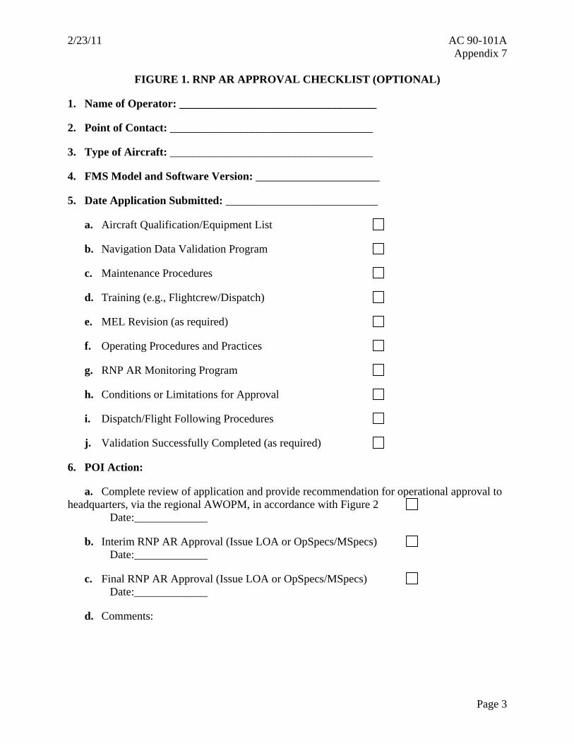
2/23/11 AC 90-101A Appendix 7
FIGURE 1. RNP AR APPROVAL CHECKLIST (OPTIONAL)
1. Name of Operator: ___________________________________
2. Point of Contact: ____________________________________
3. Type of Aircraft: ____________________________________
4. FMS Model and Software Version: ______________________
5. Date Application Submitted: ___________________________
a. Aircraft Qualification/Equipment List
b. Navigation Data Validation Program
c. Maintenance Procedures
d. Training (e.g., Flightcrew/Dispatch)
e. MEL Revision (as required)
f. Operating Procedures and Practices
g. RNP AR Monitoring Program
h. Conditions or Limitations for Approval
i. Dispatch/Flight Following Procedures
j. Validation Successfully Completed (as required)
6. POI Action:
a. Complete review of application and provide recommendation for operational approval to headquarters, via the regional AWOPM, in accordance with Figure 2
Date:_____________
b. Interim RNP AR Approval (Issue LOA or OpSpecs/MSpecs) Date:_____________
c. Final RNP AR Approval (Issue LOA or OpSpecs/MSpecs) Date:_____________
d. Comments:
Page 3

AC 90-101A 2/23/11 Appendix 7
FIGURE 2. RNP AR APPLICATION FLOW
Page 4