Embed Size (px)
Citation preview
INEL 3105 – Electrical Systems Analysis I 3/26/2019
1
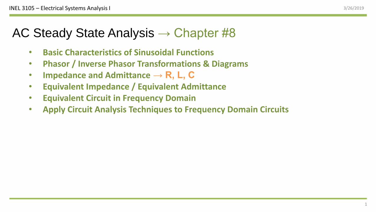
AC Steady State Analysis → Chapter #8
• Basic Characteristics of Sinusoidal Functions• Phasor / Inverse Phasor Transformations & Diagrams• Impedance and Admittance → R, L, C
• Equivalent Impedance / Equivalent Admittance• Equivalent Circuit in Frequency Domain• Apply Circuit Analysis Techniques to Frequency Domain Circuits
INEL 3105 – Electrical Systems Analysis I 3/26/2019
2
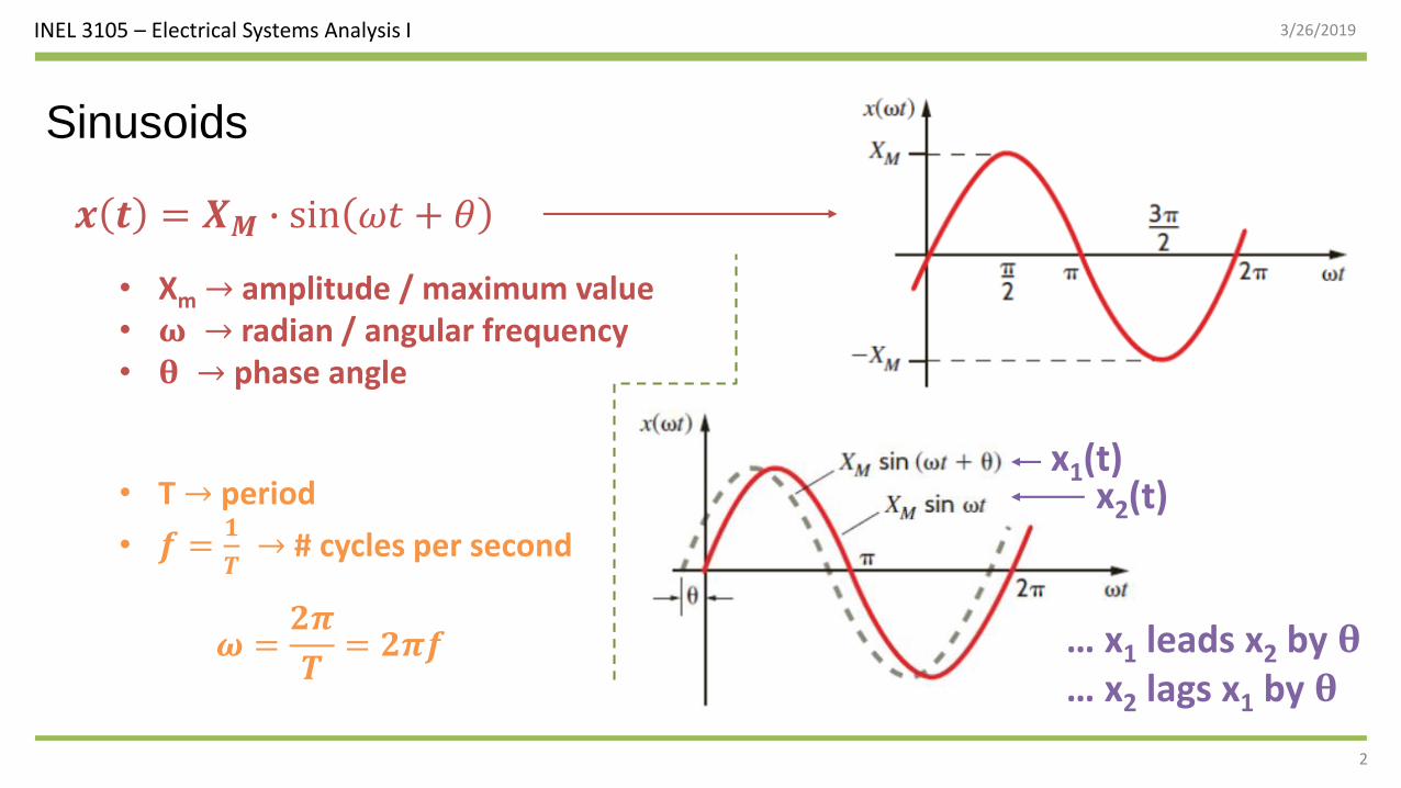
Sinusoids
• Xm → amplitude / maximum value• 𝛚 → radian / angular frequency• 𝛉 → phase angle
𝒙 𝒕 = 𝑿𝑴 ∙ sin 𝜔𝑡 + 𝜃
• T → period
• 𝒇 =𝟏
𝑻→ # cycles per second
𝝎 =𝟐𝝅
𝑻= 𝟐𝝅𝒇
x1(t)x2(t)
… x1 leads x2 by 𝛉… x2 lags x1 by 𝛉
INEL 3105 – Electrical Systems Analysis I 3/26/2019
3
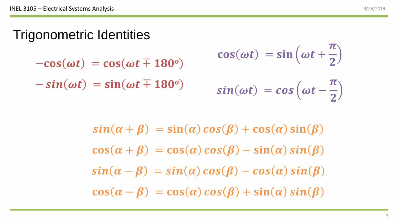
Trigonometric Identities
𝐜𝐨𝐬 𝝎𝒕 = 𝐬𝐢𝐧 𝝎𝒕 +𝝅
𝟐
𝒔𝒊𝒏 𝝎𝒕 = 𝒄𝒐𝒔 𝝎𝒕 −𝝅
𝟐
−𝐜𝐨𝐬 𝝎𝒕 = 𝐜𝐨𝐬 𝝎𝒕 ∓ 𝟏𝟖𝟎𝒐
−𝒔𝒊𝒏 𝝎𝒕 = 𝐬𝐢𝐧 𝝎𝒕 ∓ 𝟏𝟖𝟎𝒐
𝒔𝒊𝒏 𝜶 + 𝜷 = 𝐬𝐢𝐧 𝜶 𝒄𝒐𝒔 𝜷 + 𝐜𝐨𝐬 𝜶 𝐬𝐢𝐧 𝜷
𝐜𝐨𝐬 𝜶 + 𝜷 = 𝐜𝐨𝐬 𝜶 𝒄𝒐𝒔 𝜷 − 𝐬𝐢𝐧 𝜶 𝒔𝒊𝒏 𝜷
𝒔𝒊𝒏 𝜶 − 𝜷 = 𝒔𝒊𝒏 𝜶 𝒄𝒐𝒔 𝜷 − 𝒄𝒐𝒔 𝜶 𝒔𝒊𝒏 𝜷
𝐜𝐨𝐬 𝜶 − 𝜷 = 𝐜𝐨𝐬 𝜶 𝒄𝒐𝒔 𝜷 + 𝐬𝐢𝐧 𝜶 𝒔𝒊𝒏 𝜷
INEL 3105 – Electrical Systems Analysis I 3/26/2019
4
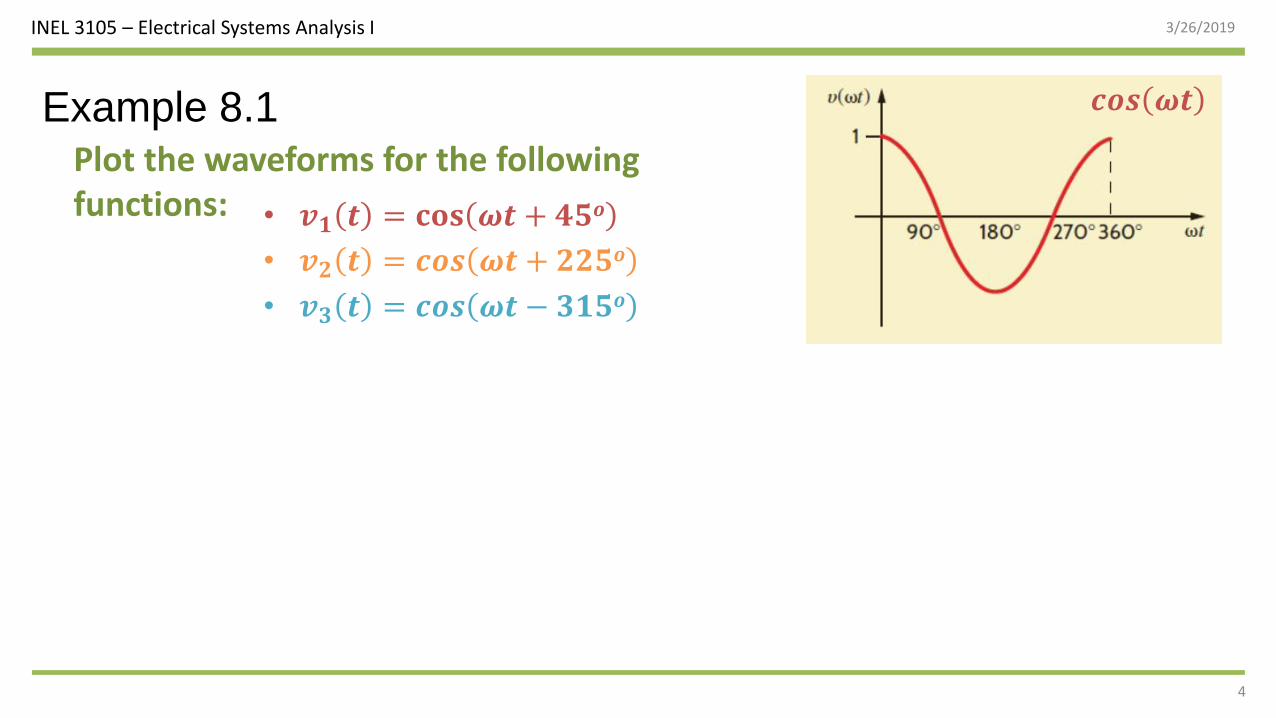
Example 8.1Plot the waveforms for the following functions: • 𝒗𝟏 𝒕 = 𝐜𝐨𝐬 𝝎𝒕 + 𝟒𝟓𝒐
• 𝒗𝟐 𝒕 = 𝒄𝒐𝒔 𝝎𝒕 + 𝟐𝟐𝟓𝒐
• 𝒗𝟑 𝒕 = 𝒄𝒐𝒔 𝝎𝒕 − 𝟑𝟏𝟓𝒐
𝒄𝒐𝒔 𝝎𝒕
INEL 3105 – Electrical Systems Analysis I 3/26/2019
5
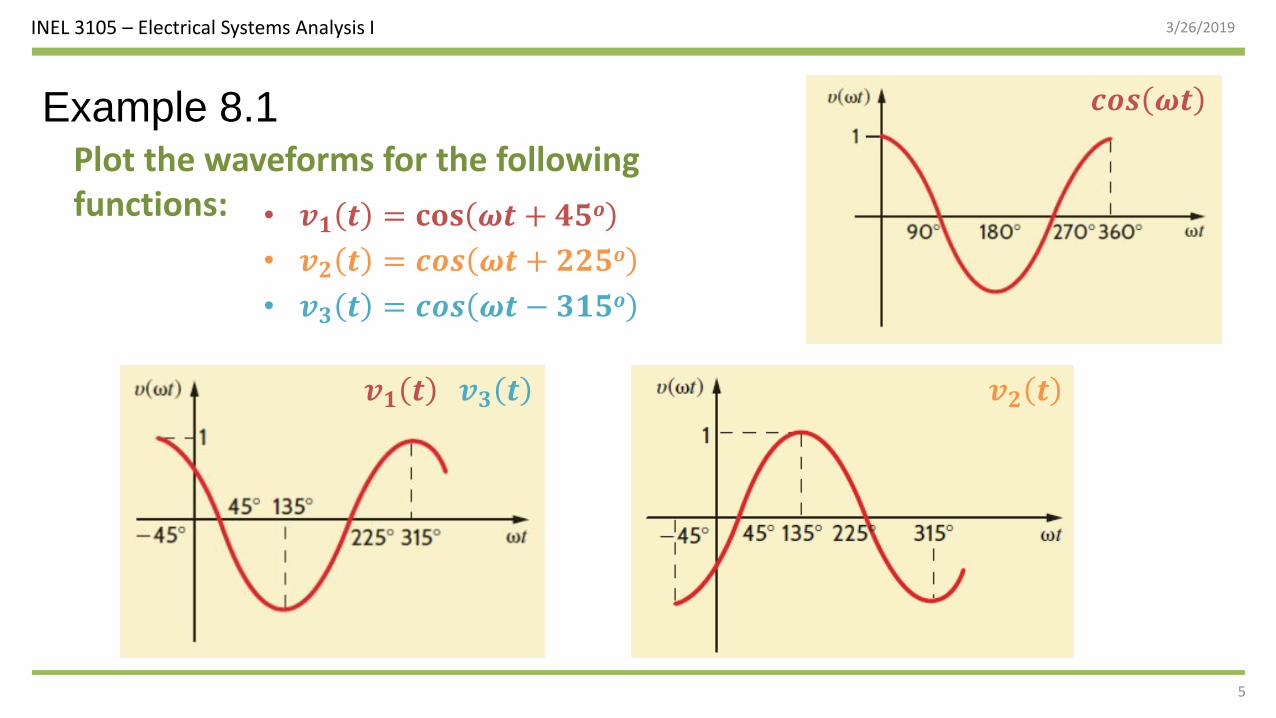
Example 8.1Plot the waveforms for the following functions: • 𝒗𝟏 𝒕 = 𝐜𝐨𝐬 𝝎𝒕 + 𝟒𝟓𝒐
• 𝒗𝟐 𝒕 = 𝒄𝒐𝒔 𝝎𝒕 + 𝟐𝟐𝟓𝒐
• 𝒗𝟑 𝒕 = 𝒄𝒐𝒔 𝝎𝒕 − 𝟑𝟏𝟓𝒐
𝒄𝒐𝒔 𝝎𝒕
𝒗𝟏 𝒕 𝒗𝟐 𝒕𝒗𝟑 𝒕
INEL 3105 – Electrical Systems Analysis I 3/26/2019
6
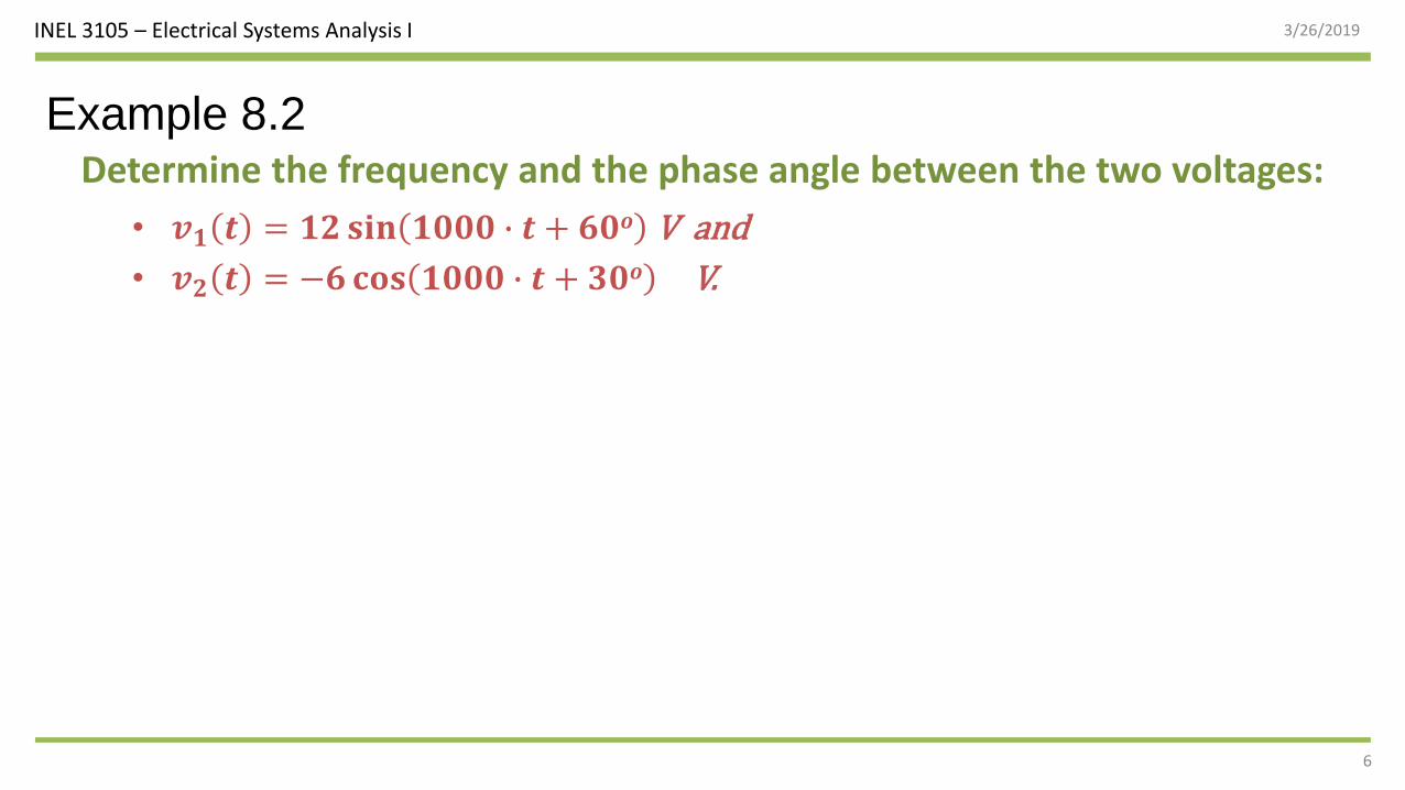
Example 8.2Determine the frequency and the phase angle between the two voltages:
• 𝒗𝟏 𝒕 = 𝟏𝟐 𝐬𝐢𝐧 𝟏𝟎𝟎𝟎 ∙ 𝒕 + 𝟔𝟎𝒐 V and
• 𝒗𝟐 𝒕 = −𝟔𝐜𝐨𝐬 𝟏𝟎𝟎𝟎 ∙ 𝒕 + 𝟑𝟎𝒐 V.

INEL 3105 – Electrical Systems Analysis I 3/26/2019
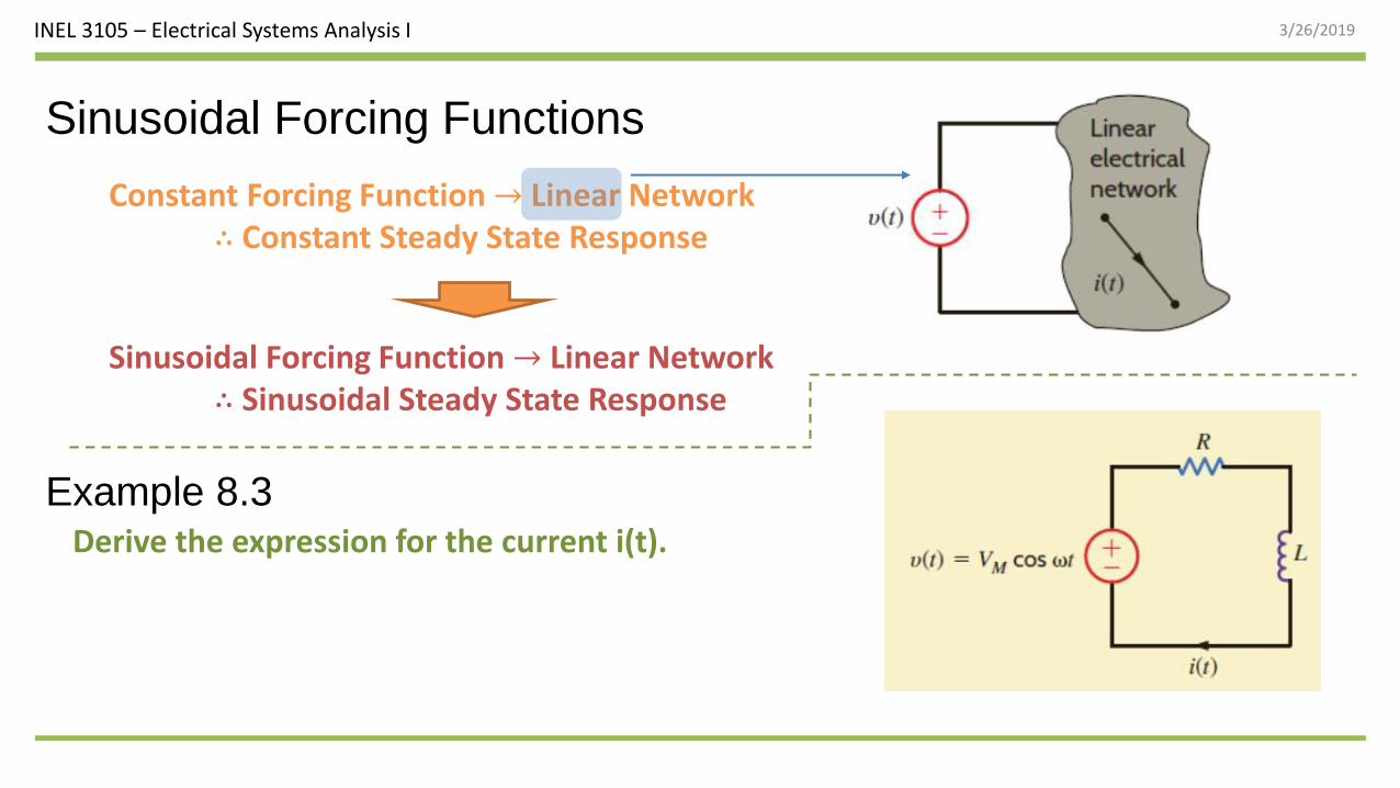
Sinusoidal Forcing Functions
Constant Forcing Function → Linear Network∴ Constant Steady State Response
Sinusoidal Forcing Function → Linear Network∴ Sinusoidal Steady State Response
INEL 3105 – Electrical Systems Analysis I 3/26/2019
Sinusoidal Forcing Functions
Constant Forcing Function → Linear Network∴ Constant Steady State Response
Sinusoidal Forcing Function → Linear Network∴ Sinusoidal Steady State Response
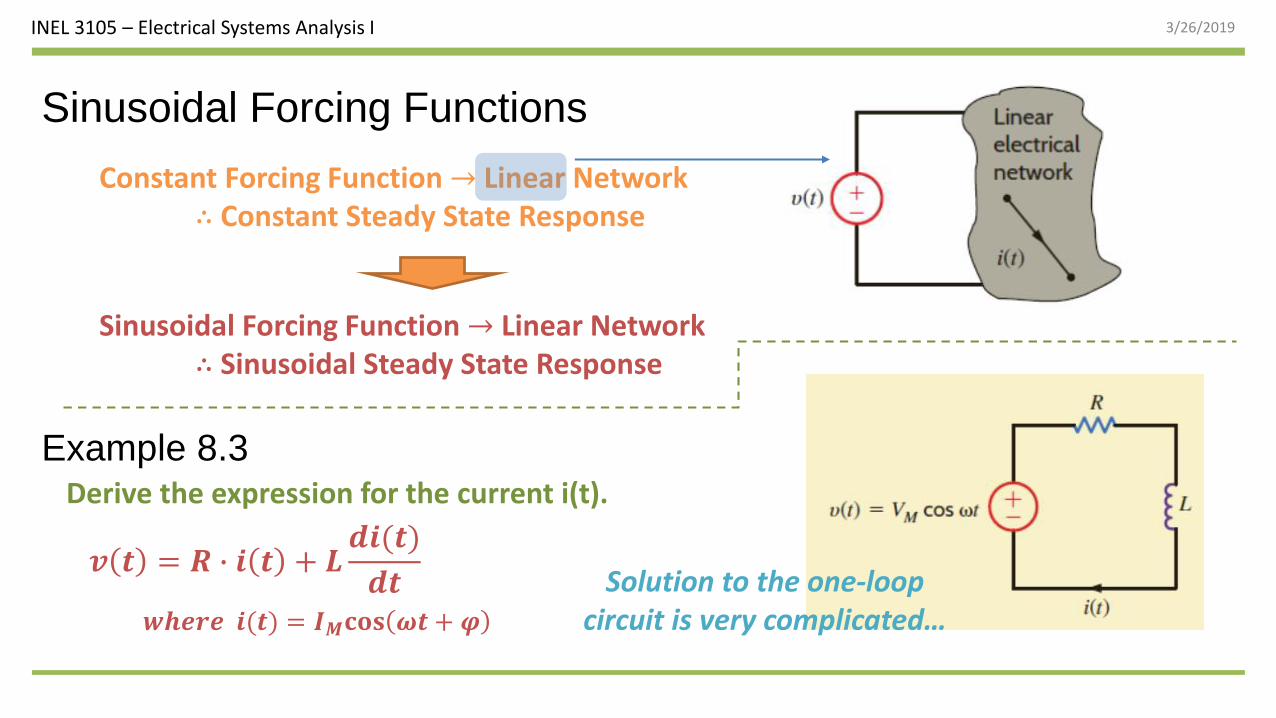
Example 8.3Derive the expression for the current i(t).
INEL 3105 – Electrical Systems Analysis I 3/26/2019
Sinusoidal Forcing Functions
Constant Forcing Function → Linear Network∴ Constant Steady State Response
Sinusoidal Forcing Function → Linear Network∴ Sinusoidal Steady State Response
Example 8.3Derive the expression for the current i(t).
𝒗 𝒕 = 𝑹 ∙ 𝒊 𝒕 + 𝑳𝒅𝒊(𝒕)
𝒅𝒕 Solution to the one-loop circuit is very complicated…𝒘𝒉𝒆𝒓𝒆 𝒊(𝒕) = 𝑰𝑴𝐜𝐨𝐬 𝝎𝒕 + 𝝋
INEL 3105 – Electrical Systems Analysis I 3/26/2019
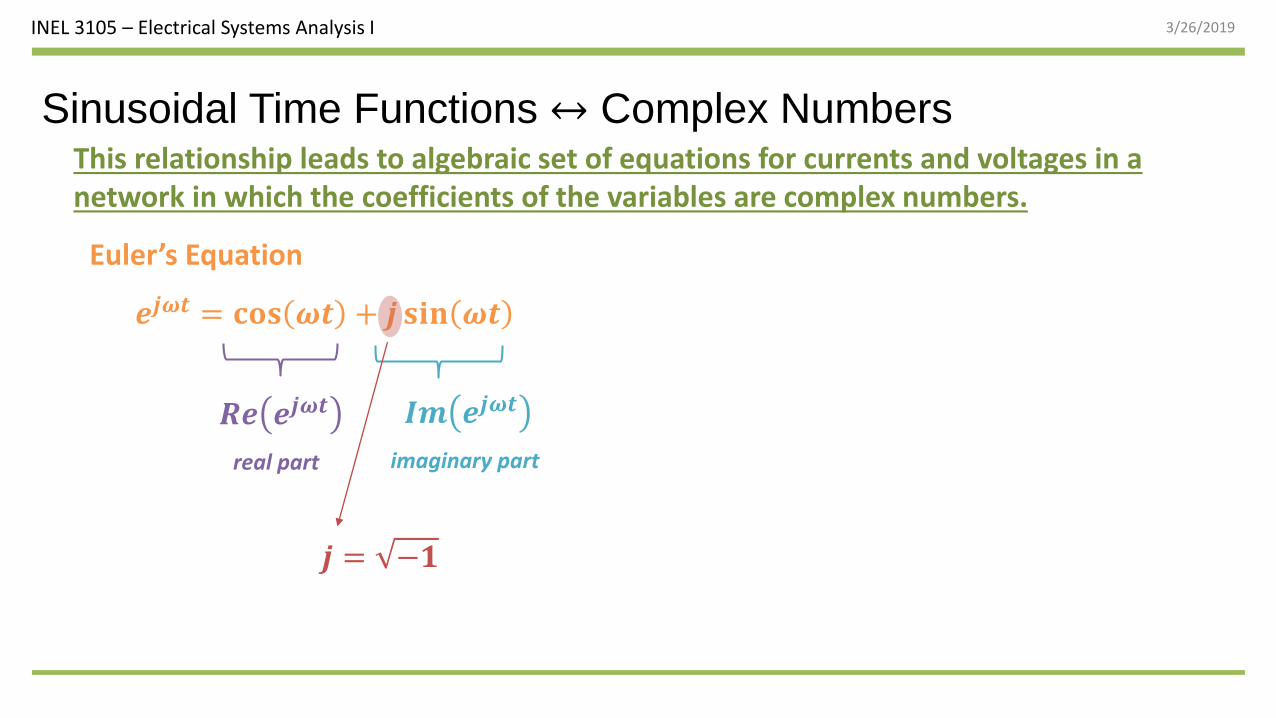
Sinusoidal Time Functions ↔ Complex NumbersThis relationship leads to algebraic set of equations for currents and voltages in a network in which the coefficients of the variables are complex numbers.
𝒆𝒋𝝎𝒕 = 𝐜𝐨𝐬 𝝎𝒕 + 𝒋 𝐬𝐢𝐧 𝝎𝒕
Euler’s Equation
𝑹𝒆 𝒆𝒋𝝎𝒕 𝑰𝒎 𝒆𝒋𝝎𝒕
real part imaginary part
𝒋 = −𝟏
INEL 3105 – Electrical Systems Analysis I 3/26/2019
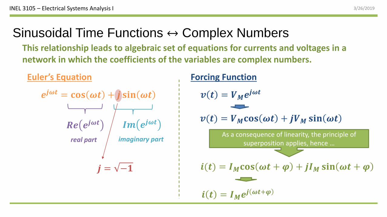
Sinusoidal Time Functions ↔ Complex NumbersThis relationship leads to algebraic set of equations for currents and voltages in a network in which the coefficients of the variables are complex numbers.
𝒆𝒋𝝎𝒕 = 𝐜𝐨𝐬 𝝎𝒕 + 𝒋 𝐬𝐢𝐧 𝝎𝒕
Euler’s Equation
𝑹𝒆 𝒆𝒋𝝎𝒕 𝑰𝒎 𝒆𝒋𝝎𝒕
real part imaginary part
𝒋 = −𝟏
Forcing Function
𝒗(𝒕) = 𝑽𝑴𝐜𝐨𝐬 𝝎𝒕 + 𝒋𝑽𝑴 𝐬𝐢𝐧 𝝎𝒕
𝒗 𝒕 = 𝑽𝑴𝒆𝒋𝝎𝒕
𝒊(𝒕) = 𝑰𝑴𝐜𝐨𝐬 𝝎𝒕 + 𝝋 + 𝒋𝑰𝑴 𝐬𝐢𝐧 𝝎𝒕 + 𝝋
𝒊 𝒕 = 𝑰𝑴𝒆𝒋 𝝎𝒕+𝝋
As a consequence of linearity, the principle of superposition applies, hence …
INEL 3105 – Electrical Systems Analysis I 3/26/2019
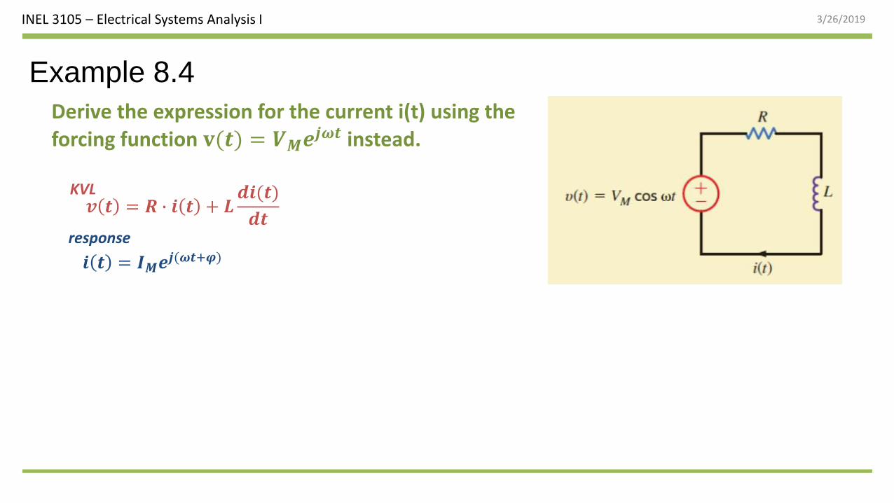
Example 8.4
Derive the expression for the current i(t) using the forcing function 𝐯(𝒕) = 𝑽𝑴𝒆𝒋𝝎𝒕 instead.
𝒗 𝒕 = 𝑹 ∙ 𝒊 𝒕 + 𝑳𝒅𝒊(𝒕)
𝒅𝒕
𝒊 𝒕 = 𝑰𝑴𝒆𝒋(𝝎𝒕+𝝋)
response
KVL
INEL 3105 – Electrical Systems Analysis I 3/26/2019
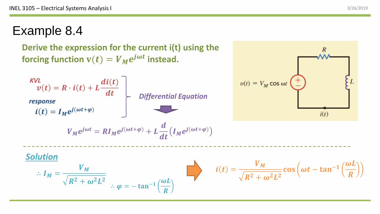
Example 8.4
Derive the expression for the current i(t) using the forcing function 𝐯(𝒕) = 𝑽𝑴𝒆𝒋𝝎𝒕 instead.
𝒊 𝒕 =𝑽𝑴
𝑹𝟐 + 𝝎𝟐𝑳𝟐𝐜𝐨𝐬 𝝎𝒕 − 𝐭𝐚𝐧−𝟏
𝝎𝑳
𝑹
𝒗 𝒕 = 𝑹 ∙ 𝒊 𝒕 + 𝑳𝒅𝒊(𝒕)
𝒅𝒕
𝒊 𝒕 = 𝑰𝑴𝒆𝒋(𝝎𝒕+𝝋)
response
KVL
Differential Equation
𝑽𝑴𝒆𝒋𝝎𝒕 = 𝑹𝑰𝑴𝒆𝒋(𝝎𝒕+𝝋) + 𝑳𝒅
𝒅𝒕𝑰𝑴𝒆𝒋(𝝎𝒕+𝝋)
∴ 𝑰𝑴 =𝑽𝑴
𝑹𝟐 + 𝝎𝟐𝑳𝟐∴ 𝝋 = −𝐭𝐚𝐧−𝟏
𝝎𝑳
𝑹
Solution
INEL 3105 – Electrical Systems Analysis I 3/26/2019
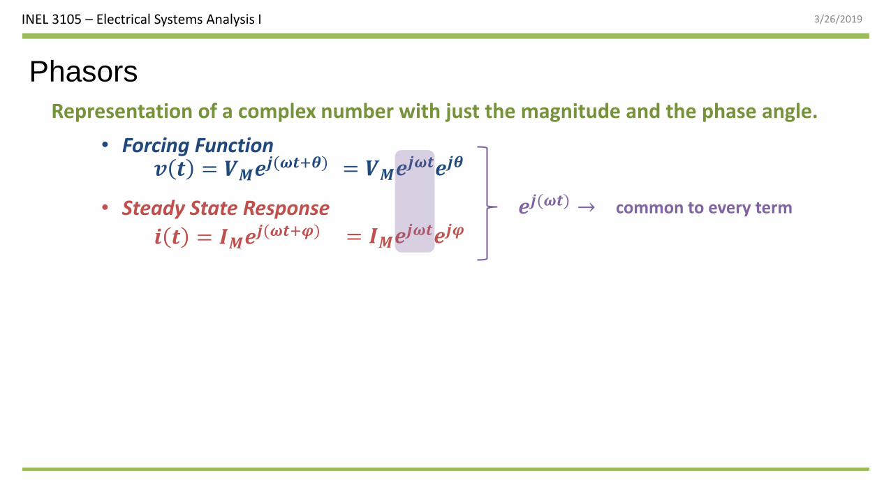
Phasors
Representation of a complex number with just the magnitude and the phase angle.
𝒗 𝒕 = 𝑽𝑴𝒆𝒋(𝝎𝒕+𝜽)• Forcing Function
• Steady State Response
𝒊 𝒕 = 𝑰𝑴𝒆𝒋(𝝎𝒕+𝝋)
common to every term𝒆𝒋(𝝎𝒕) →
= 𝑽𝑴𝒆𝒋𝝎𝒕𝒆𝒋𝜽
= 𝑰𝑴𝒆𝒋𝝎𝒕𝒆𝒋𝝋
INEL 3105 – Electrical Systems Analysis I 3/26/2019
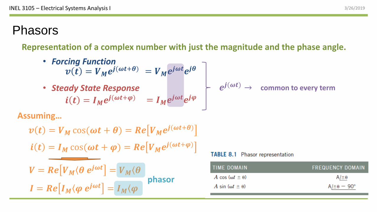
Phasors
Representation of a complex number with just the magnitude and the phase angle.
𝒗 𝒕 = 𝑽𝑴𝒆𝒋(𝝎𝒕+𝜽)• Forcing Function
• Steady State Response
𝒊 𝒕 = 𝑰𝑴𝒆𝒋(𝝎𝒕+𝝋)
common to every term
𝒗 𝒕 = 𝑽𝑴 cos(𝝎𝒕 + 𝜽) = 𝑹𝒆 𝑽𝑴𝒆𝒋(𝝎𝒕+𝜽)
𝑽 = 𝑹𝒆 𝑽𝑴 𝜽 𝒆𝒋𝝎𝒕 = 𝑽𝑴 𝜽phasor
𝒆𝒋(𝝎𝒕) →
= 𝑽𝑴𝒆𝒋𝝎𝒕𝒆𝒋𝜽
= 𝑰𝑴𝒆𝒋𝝎𝒕𝒆𝒋𝝋
𝒊 𝒕 = 𝑰𝑴 cos(𝝎𝒕 + 𝝋) = 𝑹𝒆 𝑽𝑴𝒆𝒋(𝝎𝒕+𝝋)
𝑰 = 𝑹𝒆 𝑰𝑴 𝝋 𝒆𝒋𝝎𝒕 = 𝑰𝑴 𝝋
Assuming…
INEL 3105 – Electrical Systems Analysis I 3/26/2019
Learning Assessment
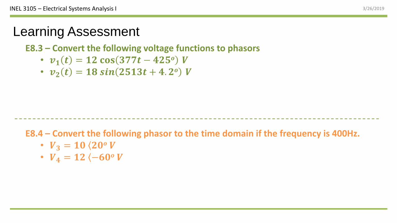
E8.4 – Convert the following phasor to the time domain if the frequency is 400Hz.• 𝑽𝟑 = 𝟏𝟎 𝟐𝟎𝒐 𝑽• 𝑽𝟒 = 𝟏𝟐 −𝟔𝟎𝒐 𝑽
E8.3 – Convert the following voltage functions to phasors• 𝒗𝟏 𝒕 = 𝟏𝟐 𝐜𝐨𝐬 𝟑𝟕𝟕𝒕 − 𝟒𝟐𝟓𝒐 𝑽• 𝒗𝟐 𝒕 = 𝟏𝟖 𝒔𝒊𝒏 𝟐𝟓𝟏𝟑𝒕 + 𝟒. 𝟐𝒐 𝑽
INEL 3105 – Electrical Systems Analysis I 3/26/2019
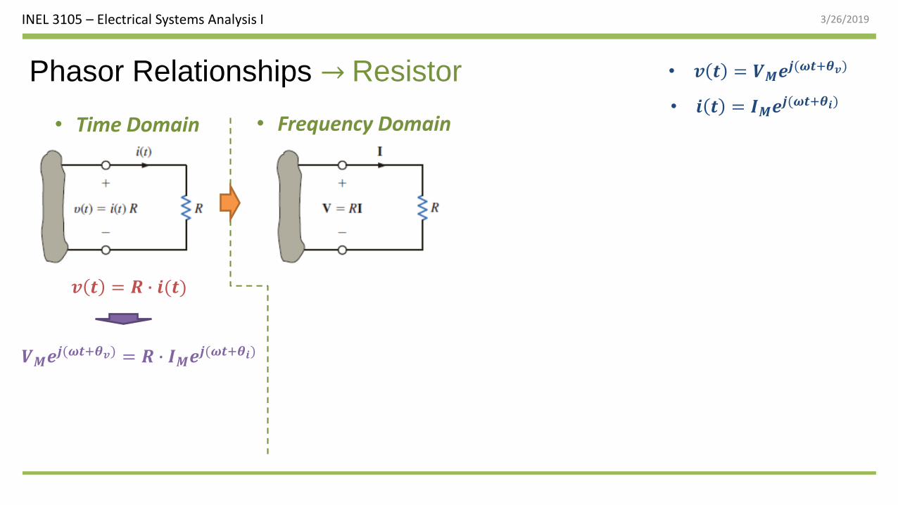
Phasor Relationships → Resistor
𝒗 𝒕 = 𝑹 ∙ 𝒊(𝒕)
𝑽𝑴𝒆𝒋(𝝎𝒕+𝜽𝒗) = 𝑹 ∙ 𝑰𝑴𝒆𝒋(𝝎𝒕+𝜽𝒊)
• 𝒊 𝒕 = 𝑰𝑴𝒆𝒋(𝝎𝒕+𝜽𝒊)
• 𝒗 𝒕 = 𝑽𝑴𝒆𝒋(𝝎𝒕+𝜽𝒗)
• Time Domain • Frequency Domain
INEL 3105 – Electrical Systems Analysis I 3/26/2019
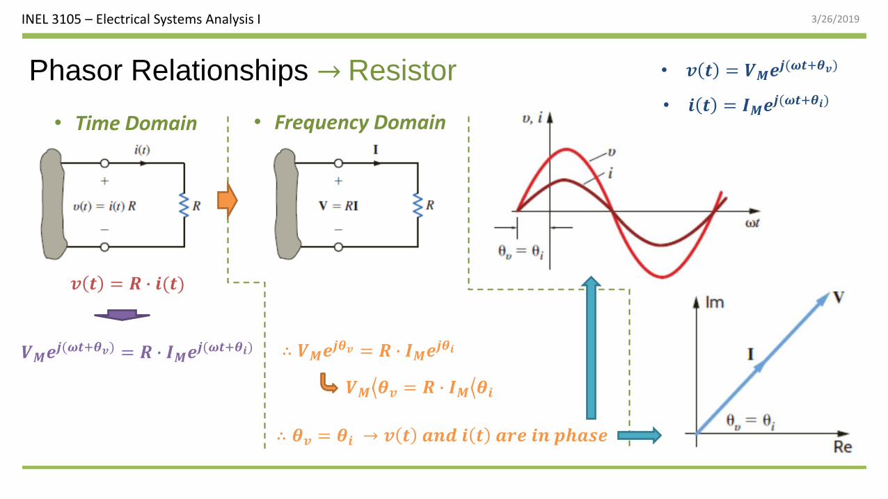
Phasor Relationships → Resistor
𝒗 𝒕 = 𝑹 ∙ 𝒊(𝒕)
𝑽𝑴𝒆𝒋(𝝎𝒕+𝜽𝒗) = 𝑹 ∙ 𝑰𝑴𝒆𝒋(𝝎𝒕+𝜽𝒊) ∴ 𝑽𝑴𝒆𝒋𝜽𝒗 = 𝑹 ∙ 𝑰𝑴𝒆𝒋𝜽𝒊
𝑽𝑴 𝜽𝒗 = 𝑹 ∙ 𝑰𝑴 𝜽𝒊
• 𝒊 𝒕 = 𝑰𝑴𝒆𝒋(𝝎𝒕+𝜽𝒊)
• 𝒗 𝒕 = 𝑽𝑴𝒆𝒋(𝝎𝒕+𝜽𝒗)
∴ 𝜽𝒗 = 𝜽𝒊 → 𝒗 𝒕 𝒂𝒏𝒅 𝒊 𝒕 𝒂𝒓𝒆 𝒊𝒏 𝒑𝒉𝒂𝒔𝒆
• Time Domain • Frequency Domain
INEL 3105 – Electrical Systems Analysis I 3/26/2019
19
Example 8.6
Basic Concepts
If the voltage 𝒗 𝒕 = 𝟐𝟒𝐜𝐨𝐬 𝟑𝟕𝟕𝒕 + 𝟕𝟓𝒐 V is applied to a 6-Ω resistor, find the resultant current.
INEL 3105 – Electrical Systems Analysis I 3/26/2019
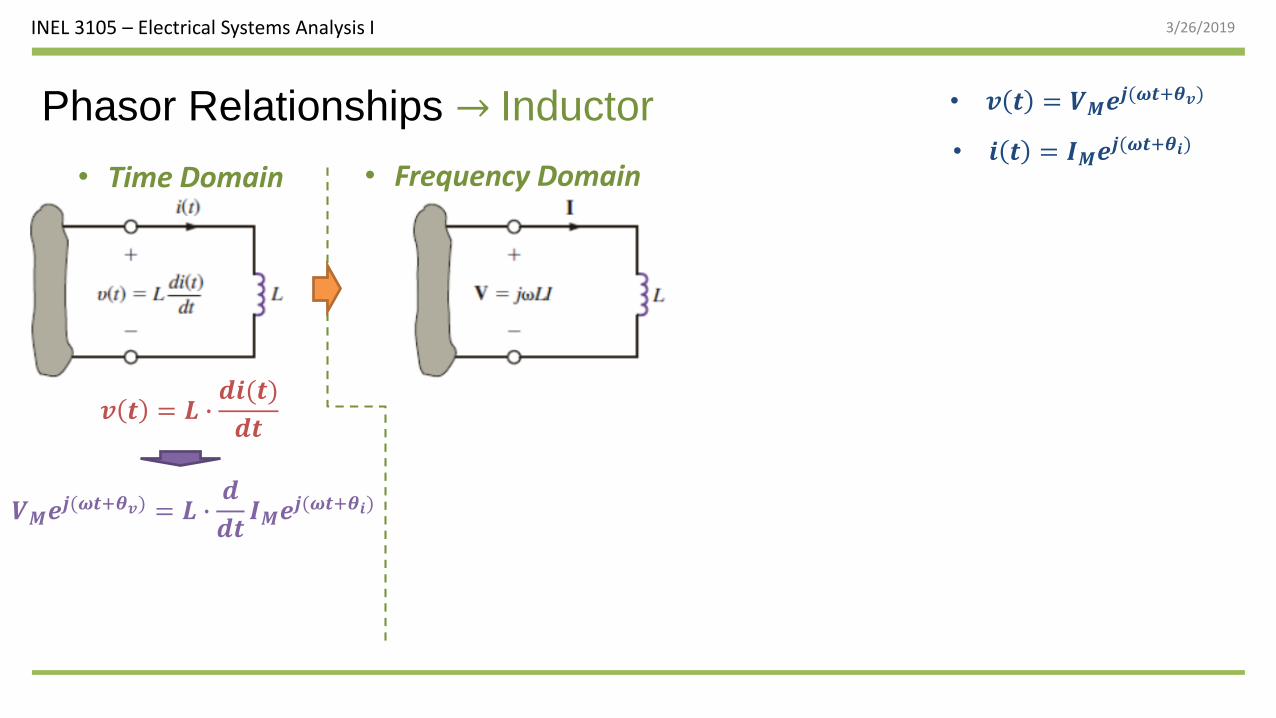
Phasor Relationships → Inductor
𝒗 𝒕 = 𝑳 ∙𝒅𝒊(𝒕)
𝒅𝒕
𝑽𝑴𝒆𝒋(𝝎𝒕+𝜽𝒗) = 𝑳 ∙𝒅
𝒅𝒕𝑰𝑴𝒆𝒋(𝝎𝒕+𝜽𝒊)
• 𝒊 𝒕 = 𝑰𝑴𝒆𝒋(𝝎𝒕+𝜽𝒊)
• 𝒗 𝒕 = 𝑽𝑴𝒆𝒋(𝝎𝒕+𝜽𝒗)
• Time Domain • Frequency Domain
INEL 3105 – Electrical Systems Analysis I 3/26/2019
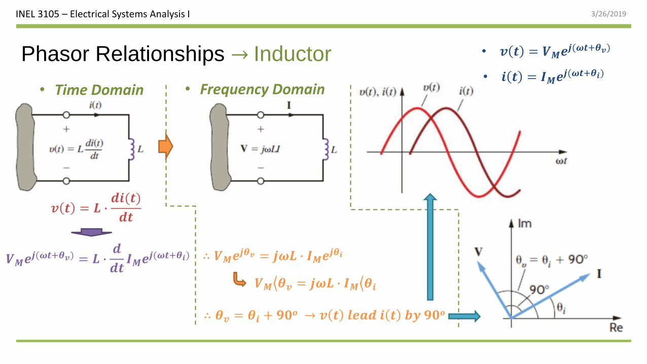
Phasor Relationships → Inductor
𝒗 𝒕 = 𝑳 ∙𝒅𝒊(𝒕)
𝒅𝒕
𝑽𝑴𝒆𝒋(𝝎𝒕+𝜽𝒗) = 𝑳 ∙𝒅
𝒅𝒕𝑰𝑴𝒆𝒋(𝝎𝒕+𝜽𝒊) ∴ 𝑽𝑴𝒆𝒋𝜽𝒗 = 𝒋𝝎𝑳 ∙ 𝑰𝑴𝒆𝒋𝜽𝒊
𝑽𝑴 𝜽𝒗 = 𝒋𝝎𝑳 ∙ 𝑰𝑴 𝜽𝒊
∴ 𝜽𝒗 = 𝜽𝒊 + 𝟗𝟎𝒐 → 𝒗 𝒕 𝒍𝒆𝒂𝒅 𝒊 𝒕 𝒃𝒚 𝟗𝟎𝒐
• 𝒊 𝒕 = 𝑰𝑴𝒆𝒋(𝝎𝒕+𝜽𝒊)
• 𝒗 𝒕 = 𝑽𝑴𝒆𝒋(𝝎𝒕+𝜽𝒗)
• Time Domain • Frequency Domain
INEL 3105 – Electrical Systems Analysis I 3/26/2019
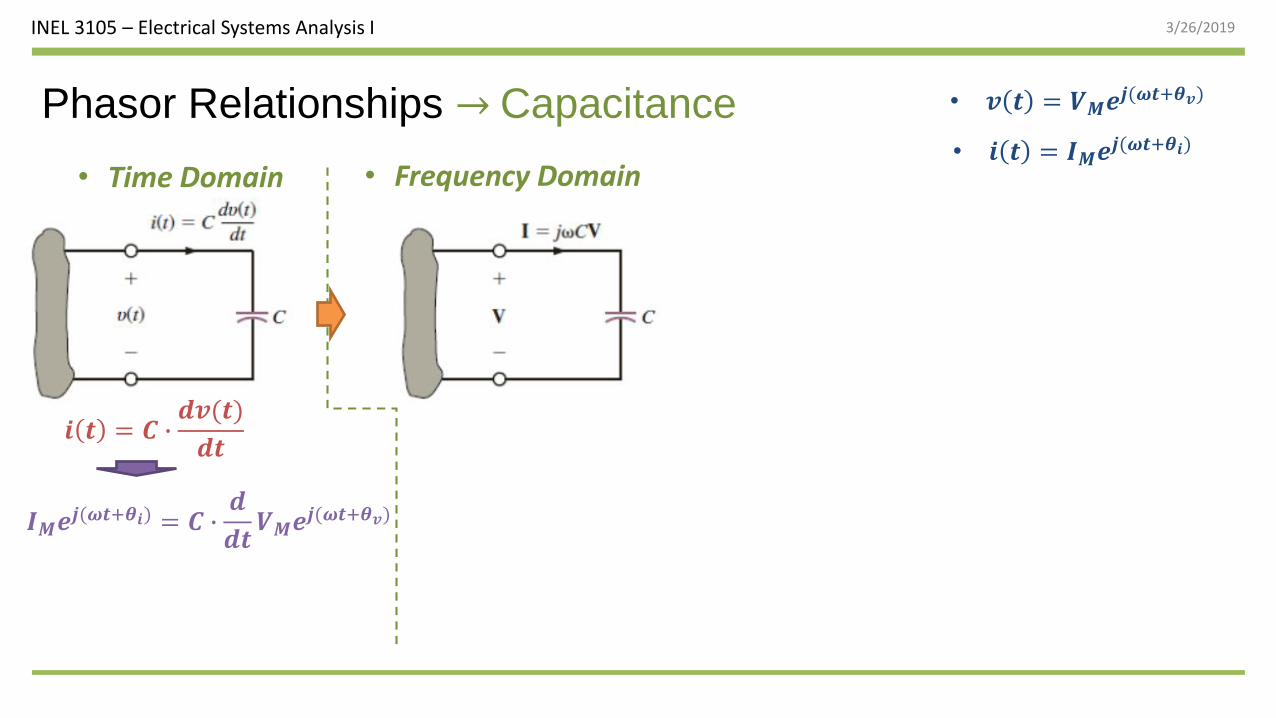
Phasor Relationships → Capacitance
𝒊 𝒕 = 𝑪 ∙𝒅𝒗(𝒕)
𝒅𝒕
𝑰𝑴𝒆𝒋(𝝎𝒕+𝜽𝒊) = 𝑪 ∙𝒅
𝒅𝒕𝑽𝑴𝒆𝒋(𝝎𝒕+𝜽𝒗)
• 𝒊 𝒕 = 𝑰𝑴𝒆𝒋(𝝎𝒕+𝜽𝒊)
• 𝒗 𝒕 = 𝑽𝑴𝒆𝒋(𝝎𝒕+𝜽𝒗)
• Time Domain • Frequency Domain
INEL 3105 – Electrical Systems Analysis I 3/26/2019
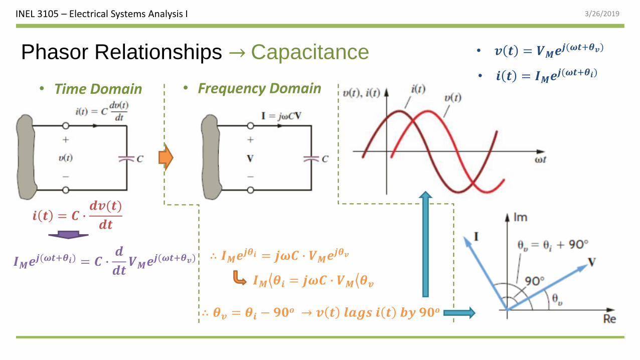
Phasor Relationships → Capacitance
𝒊 𝒕 = 𝑪 ∙𝒅𝒗(𝒕)
𝒅𝒕
𝑰𝑴𝒆𝒋(𝝎𝒕+𝜽𝒊) = 𝑪 ∙𝒅
𝒅𝒕𝑽𝑴𝒆𝒋(𝝎𝒕+𝜽𝒗) ∴ 𝑰𝑴𝒆𝒋𝜽𝒊 = 𝒋𝝎𝑪 ∙ 𝑽𝑴𝒆𝒋𝜽𝒗
𝑰𝑴 𝜽𝒊 = 𝒋𝝎𝑪 ∙ 𝑽𝑴 𝜽𝒗
∴ 𝜽𝒗 = 𝜽𝒊 − 𝟗𝟎𝒐 → 𝒗 𝒕 𝒍𝒂𝒈𝒔 𝒊 𝒕 𝒃𝒚 𝟗𝟎𝒐
• 𝒊 𝒕 = 𝑰𝑴𝒆𝒋(𝝎𝒕+𝜽𝒊)
• 𝒗 𝒕 = 𝑽𝑴𝒆𝒋(𝝎𝒕+𝜽𝒗)
• Time Domain • Frequency Domain
INEL 3105 – Electrical Systems Analysis I 3/26/2019
24
Example 8.8If the voltage 𝒗 𝒕 = 𝟏𝟎𝟎𝐜𝐨𝐬 𝟑𝟏𝟒𝒕 + 𝟏𝟓𝒐 V is applied to a 100-μF capacitor, find the resultant current.