Embed Size (px)
Citation preview

Art. # 608 637 54 / Edition 1.2 February 2004 / Printed in Germany
Driv
es
AC Servo Motors
JL1 Motor Series
Installation Manual

Drives
Edition 1.2
Jetter AG reserves the right to make alterations to its products in the interest of technical progress. These alterations need not to be documented in every single case.
This manual and the information contained herein have been compiled with due diligence. Jetter AG shall not be liable for errors contained herein or for incidental or consequential damage in connection with the furnishing, performance, or use of this material.
The brand names and product names used in this manual are trade marks or registered trade marks of the respective title owner.
2 Jetter AG

JL1 Motor Series
How to Contact us:Jetter AGGräterstraße 2D-71642 LudwigsburgGermany
Phone - Switchboard: 07141/2550-0Phone - Sales: 07141/2550-433Phone - Technical Hotline: 07141/2550-444
Telefax: 07141/2550-425E-Mail - Sales: [email protected] - Technical Hotline: [email protected] address: http://www.jetter.de
This Manual is an Integral Part of theJL1 Motor Series:
To be entered by the customer:
© Copyright 2004 by Jetter AG. Alle rights reserved.
Type:
Serial No:
Year of construction:
Order No.:
Inventory #:
Place of operation:
Jetter AG 3

Drives
Significance of this Installation ManualThis installation manual is an integral part of the Jetter motor belonging to the motor series JL1, and
• must be kept in a way that it is always at hand until the Jetter motor of the JL1 series will be disposed of.
• If the Jetter motor of the JL1 series is sold, transferred or lent, this manual must be handed over.
In any case you encounter difficulties to clearly understand this installation manual, please contact the manufacturer.We would appreciate any kind of suggestion and contributions on your part and would ask you to inform us or the write us. This will help us to produce manuals that aremore user-friendly and to address your wishes and requirements.
From the Jetter motor of the JL1 series may result unavoidable residual risks to persons and property. For this reason, any person who has to deal with the transport, installation, operation, maintenance, and repair of the motor belonging to the JL1 motor series must have been familiarised with it and must be aware of these dangers.Therefore, this person must carefully read, understand and observe this manual, and especially the safety instructions.
Missing or inadequate knowledge of the manual results in the loss of any claim of liability on part of Jetter AG. Therefore, the operating company is recommended to have the instruction of the persons concerned confirmed in writing.
4 Jetter AG

JL1 Motor Series Table of Contents
Table of Contents1 Safety Instructions 72 Installing JL1 Motors 133 Operating Conditions 194 Physical Dimensions 205 Technical Data 216 Description of Connections 247 Maintaining the Motor 268 Troubleshooting 27
AppendicesAppendix A: Glossary 30Appendix B: List of Abbreviations 31Appendix C: Index of Illustrations 32Appendix D: Index 33
Jetter AG 5

Table of Contents Drives
6 Jetter AG

JL1 Motor Series 1 Safety Instructions
Inhalt 1 Safety InstructionsThe Jetter motor series JL1 is in line with the current state of the art. These motors comply with the safety regulations and standards in force. Special emphasis was given to the safety of the users.
Of course, the following regulations apply to the user:
• relevant accident prevention regulations;• accepted safety rules;• EC guidelines and other country-specific regulations.
Usage as Agreed Upon
Usage as agreed upon includes operation in accordance with the installation manual.These motors are designed and approved for operation in electrical installations or machines only. They are used as drives for e.g. conveyors, packaging machines, production plants and handling machines for example in the semiconductor industry.
Usage Other than Agreed Upon
The Jetter JL1 motors must not be used in technical systems which to a very high degree have to be fail save, e.g. ropeways and aeroplanes.If the motors are to be run under operating conditions, which differ from the conditions mentioned in chapter 3, page 19, the manufacturer is to be contacted beforehand.
Who is Allowed to Install Motors of the Jetter Motor Series JL1?
Only instructed, trained and authorised persons are permitted to install the motors.Mounting and backfitting may only be carried out by specially trained personnel, as specific know-how in the fields of mechanical and electrical engineering will be required.Make sure that in the working area only authorised persons are present and that other persons are not exposed to danger by the installation works.
Decommissioning and Disposing of Motors belonging to the Jetter Motor Series JL1
The environmental regulations for the respective country apply to decommissioning and disposing of motors on the operating company’s premises.
Jetter AG 7

1 Safety Instructions Drives
Description of Symbols
Danger
This sign is to indicate a possible impending danger of serious physical damage or death.
Caution
This sign is to indicate a possible impending danger of light physical damage. This sign is also to warn you of material damage.
Important!
This sign is to indicate a possible impending situation which might bring damage to the product or to its surroundings.
Note!
This sign is to indicate an application, e.g installation, and other useful information.
· / - Enumerations are marked by full stops, strokes or scores.
Operating instructions are marked by this arrow.
Automatically running processes or results to be achieved are marked by this arrow.
8 Jetter AG

JL1 Motor Series 1 Safety Instructions
Ensure your Own SafetyIsolate the JL1 motors from the mains, if maintenance works have to be carried out on your machines. By doing so, you will prevent accidents resulting from electric voltage and moving parts.
Modifications and Alterations to the Motors
• Due to safety reasons, no modifications and alterations to the motors and their functions are allowed. Any modifications to the motors not expressly authorised by the manufacturer will result in a loss of any liability claims to Jetter AG.
• The original parts are specifically designed for the Jetter motors. Parts and equipment of other manufacturers are not tested on our part, and are, therefore, not released by us. The installation of such parts may impair the safety and the proper functioning of the motors.
• For any damages resulting from usage other than agreed upon, e.g. the use of non original parts and equipment, any claims with respect to liability of Jetter AG are excluded.
Malfunctions
Information Signs and Labels
Malfunctions or other damages are to be reported to an authorised person at once.
The motors must be protected from improper or inadvertent use.
Only qualified experts are allowed to carry out repairs.
Safety and protective devices, e.g. the thermal motor circuit-breaker, must never be shunted or by-passed.
Dismantled protective equipment, such as the thermal motor circuit-breaker, must be reattached prior to commissioning and checked for proper functioning.
Writings, information signs, and labels always have to be observed and kept readable.
Damaged or unreadable information signs and labels are to be exchanged.
Jetter AG 9

1 Safety Instructions Drives
Instructions on EMIThe noise immunity of a system corresponds to the weakest component of the system. For this reason, correct wiring and shielding of the cables is important.
Important!
Measures for increasing immunity to interference of your installation:
Shielding must be done on both ends of the applicable cables.
The entire perimeter of the shield must be drawn behind the shielding clamp of the metallised connector housing, resp. of the EMC gland bushing, with the greatest possible surface area (impedance shielding), and then be clamped under a strain relief.
When connecting signal lines:The strain relief must be connected with a grounded surface directly and extensively.
When male connectors are used: Use metallised connectors only. Please take care of direct contact between the strain relief and the motor housing.
As a rule, physical separation should be maintained between signal and power lines. The distance between such lines has to be greater than 20 cm.
The stripped conductor ends must be as short as possible.
Use either Jetter brand motor cables or motor cables according to applicable standards.
10 Jetter AG

JL1 Motor Series 1 Safety Instructions
Residual Dangers
Hazards during Operation
Hazard caused by high operating voltage!
If the motor is not connected up correctly and not isolated from the mains, for example during installation, maintenance, and repair, you can get an electric shock.Please observe the following precautions in order to avoid injuries such as muscle cramps, burns, unconsciousness, respiratory standstill, and possibly death:
Do not touch any terminals and electric components while the motor is running.
Check all live parts for protection by an electrical barrier. Extremely hazardous voltages of up to 900 V may occur.
Do not disconnect the motor under voltage. Capacitors of the servo amplifier can store dangerous voltages for at least 5 minutes after the power has been switched off.
Risk of injuries to upper and lower limbs!
You run the risk of injuring your upper and lower limbs when the drive shaft is rotating.
Never touch a rotating drive shaft.
Make sure that hazards to persons are precluded even when the drive is moving unintentionally.
Hazard of burning!
You can get burnt when touching the motor. The surface temperature of a motor during operation may come to 100 °C.
Do not touch the motor during operation.
Jetter AG 11

1 Safety Instructions Drives
Hazards after POWER is turned OFF
Danger resulting from electric shock!
You can get an electric shock if you don't wait at least one minute after switching off before you continue working with the motor.Please observe the following precautions in order to avoid injuries such as muscle cramps, burns, unconsciousness, respiratory standstill, and possibly death:
Wait at least one minute after switching off before disconnecting the motor from mains or disassembling it.The control and power connections may still be live, even though the motor is not turning.
Hazard of burning!
You can get burnt when touching the motor during the cooling-off phase.
Check the motor temperature and wait until the motor has cooled off to 40 °C before touching it.
12 Jetter AG

JL1 Motor Series 2 Installing JL1 Motors
2 Installing JL1 MotorsScope of Delivery
• Motor of the motor series JL1
• Installation Manual
Mounting Accessories (not included in the scope of delivery)
• Motor connecting cable, see chapter 6
• Resolver or Hiperface cable; refer to chapter 6
• Servo amplifier
Note!
If you are not sure which mounting accessories you require, please contact Jetter AG.
Important!
Measures to avoid damages to the motor in transit and storage:
Servo motors are high-precision devices. In particular, shafts and flanges are susceptible to damage during installation. For this reason, do not apply excess force when mounting the motor. Strokes, such as strokes of the hammer, or other use of force will result in damages to ball bearings and shafts.
Protect motors against inadmissible loads. In particular, components must not be twisted and/or isolation spacings must not be altered during transport and handling.
Motors have to be disconnected from the supply during installation and wiring, i.e. none of the devices to be connected must be energised.
Also observe the instructions given in the connection diagram of the installation / set-up manual to the servo amplifier used.
Prior to installation carefully clean the shaft only using diluent for cellulose lacquers. On no account immerse the motor in diluent or spray it with diluent.
Avoid the use of servo motors in a corrosive environment, such as a sulphurous atmosphere. Such ambient conditions will have negative effects on the service life of the motor.
Jetter AG 13

2 Installing JL1 Motors Drives
Mechanical Installation
Fig. 1: Example: Fitting of a Power Output Element
Prior to installing the motor check it for possible transport damages.
For fitting couplings, gear wheels or pulleys use by all means the motor shaft thread intended for this purpose; refer to Fig. 1. If possible, heat up the power output elements prior to their installation.
For fitting power output elements use as far as possible only frictional collets and couplings which are free from backlash. Pay attention to the correct alignment of the coupling (as little unbalanced mass as possible). A balance error produces vibrations and will damage ball bearings and coupling.
When using timing belts by all means observe the indicated permissible radial forces. Radial loads exceeding the limits will significantly reduce the service life of motors.
Check power output elements (coupling, gear drive, pulley) for tight fit and correct set-up (observe admissible radial and axial forces).
If possible, avoid loading the motor shaft with axial forces since axial loads will significantly reduce the motor service life.
Under all circumstances avoid a hyperstatic arrangement of the motor shaft bearings, for example, by using a rigid coupling and an external additional bearing (e.g. in the gear drive).
Spacer Washer
14 Jetter AG

JL1 Motor Series 2 Installing JL1 Motors
Fig. 2: Mounting Positions of JL1 Motors
The installation location must be free from conductive and corrosive substances. For encapsulated installation please consult our application department.
Ensure unobstructed ventilation of the motors and observe the ambient and flange temperature; see also chapter 3. During operation the maximum flange temperature of 65 °C must not be exceeded.
Protect the motors against liquids soaking into the bearing in case the shaft end is installed upwards (design V3); refer to Fig. 2.
Observe the given pole count of the motor (6) and the resolver (2). If required, set these values at your servo amplifier. When using Jetter servo amplifiers no setting is necessary.
In order to disassemble gears, pulleys etc. please use a pulling device according to Fig. 3.
All motor connection lines, such as cables and pipes, have to be run in a way that nobody gets entangled in them.
When laying lines, the bending radiuses given in the cable specifikations must be observed.
IM B 5 (B5)
Motor Design
IM V 1 (V1) IM V 3 (V3)
Drive End Non-Drive End
Jetter AG 15

2 Installing JL1 Motors Drives
Fig. 3: Example: Pulling off a Power Output Element
Electrical Installation
Check for correct motor and servo amplifier assignment.
Compare rated voltage and continuous rated current of servo amplifier and motor.
Carry out wiring according to the wiring diagram given in the operating manual of the servo amplifier.
Select the cables according to standards.
Check whether all ground cables are connected (double earthing).
To ensure that installation is carried out in conformance with EMC regulations, the following items have to be observed:
– Ground the mounting plate and the motor housing.;– If possible, run control cables and power cables separately;– Connect resolver;– Connect motor cables, place toroidal cores or motor choke near to the
servo amplifier, connect shields on both ends of the cables;– Use shielded terminals or EMC-compatible connectors;– Connect holding brake, if available, and connect shields on both sides
of the cables.
Spacer Washer
16 Jetter AG

JL1 Motor Series 2 Installing JL1 Motors
Checking the Installation
Notes on Safety as regards the Installation
In addition, observe the explanations given in the operating manual of the servo amplifier to ensure EMC-compatible installation. In particular, connect the shields according to the connection diagrams given in the operating manual of the servo amplifier.
To connect resolvers or power units you can use prefabricated cables available from Jetter or opt for self-made cables. Please refer to chapter 6.
Check motor and servo amplifier wiring and connections by means of the connection diagrams used.
Check the holding brake, if existing, for proper functioning. (Brake must release if 24 V are applied).
Check to see whether the motor rotor can be turned easily (a possibly existing brake must be released beforehand). Watch out for unusual scraping noises.
Check to see whether all necessary protection measures against accidental contact with live or moving parts have been taken.
Carry out any other checks specific to or required for your system.
Put the drive into operation according to the operating manual of the servo amplifier.
When using multi-axis systems, put each drive unit (servo amplifier/motor) separately into operation.
Danger resulting from electric shock!
If the Jetter motor JL1 is not isolated from the mains, for example during installation, maintenance, and repair, you can get an electric shock.Please observe the following precautions in order to avoid injuries such as muscle cramps, burns, unconsciousness, respiratory standstill, and possibly death.
Have works on the electric and electronic system performed by qualified personnel only.
Isolate the Jetter motor JL1 from the mains (pull out the mains plug) when working on the control system.
Prior to commissioning, do the following:
• reattach dismantled protective equipment, e.g. thermostatic circuit-breakers, and check it for proper functioning;
• protect the Jetter JL1 motors against accidental contact with live parts and components;
Jetter AG 17

2 Installing JL1 Motors Drives
• provide a durable connection with the power supply of the Jetter JL1 motor;
• each commissioning, even a short functional test, must always be carried out with correctly connected PE bus;
Hazard of burning!
Do not disconnect the motor under voltage.Capacitors of the servo amplifier can store dangerous voltages for at least 5 minutes after the power has been switched off.
Measure the voltage in the DC-link circuit and wait until it has fallen below 40 V.
18 Jetter AG
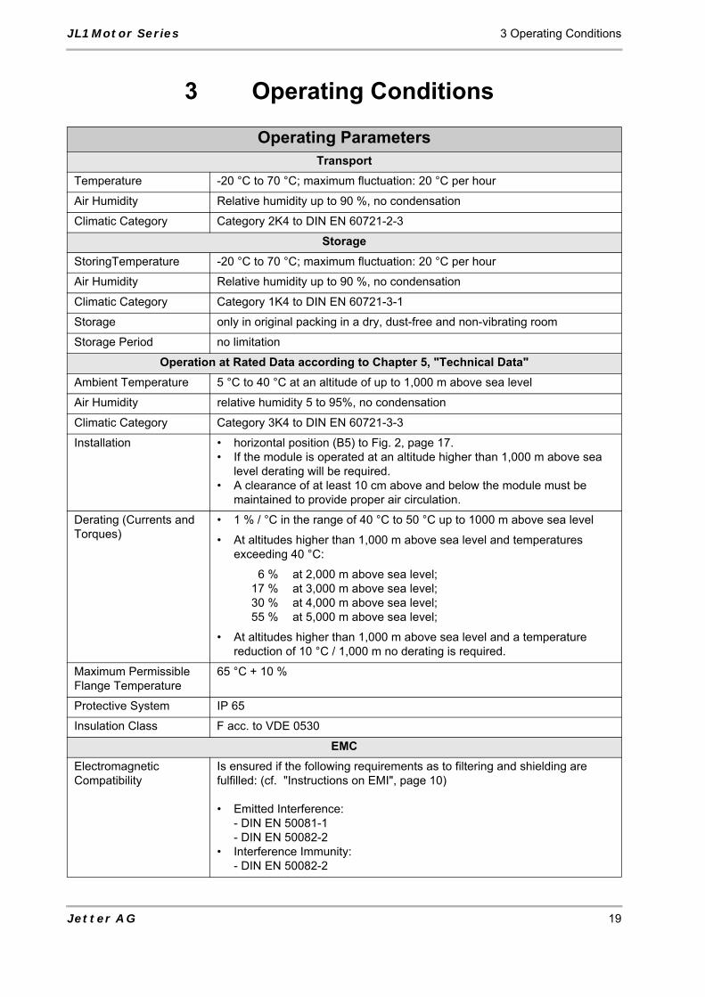
JL1 Motor Series 3 Operating Conditions
Jetter AG 19
3 Operating Conditions
Operating ParametersTransport
Temperature -20 °C to 70 °C; maximum fluctuation: 20 °C per hour
Air Humidity Relative humidity up to 90 %, no condensation
Climatic Category Category 2K4 to DIN EN 60721-2-3
StorageStoringTemperature -20 °C to 70 °C; maximum fluctuation: 20 °C per hour
Air Humidity Relative humidity up to 90 %, no condensation
Climatic Category Category 1K4 to DIN EN 60721-3-1
Storage only in original packing in a dry, dust-free and non-vibrating room
Storage Period no limitation
Operation at Rated Data according to Chapter 5, "Technical Data"Ambient Temperature 5 °C to 40 °C at an altitude of up to 1,000 m above sea level
Air Humidity relative humidity 5 to 95%, no condensation
Climatic Category Category 3K4 to DIN EN 60721-3-3
Installation • horizontal position (B5) to Fig. 2, page 17.• If the module is operated at an altitude higher than 1,000 m above sea
level derating will be required.• A clearance of at least 10 cm above and below the module must be
maintained to provide proper air circulation.
Derating (Currents and Torques)
• 1 % / °C in the range of 40 °C to 50 °C up to 1000 m above sea level
• At altitudes higher than 1,000 m above sea level and temperatures exceeding 40 °C:
6 %17 %30 %55 %
at 2,000 m above sea level;at 3,000 m above sea level;at 4,000 m above sea level;at 5,000 m above sea level;
• At altitudes higher than 1,000 m above sea level and a temperature reduction of 10 °C / 1,000 m no derating is required.
Maximum Permissible Flange Temperature
65 °C + 10 %
Protective System IP 65
Insulation Class F acc. to VDE 0530
EMCElectromagnetic Compatibility
Is ensured if the following requirements as to filtering and shielding are fulfilled: (cf. "Instructions on EMI", page 10)
• Emitted Interference:- DIN EN 50081-1- DIN EN 50082-2
• Interference Immunity: - DIN EN 50082-2

4 Physical Dimensions Drives
20 Jetter AG
4 Physical Dimensions
Fig. 4: Mounting Dimensions of the JL1 Motor Series
All dimensions in mm
83 11398 128
JL1-0010JL1-0020
K K1TypeMotor withResolver * )
Ø 6
h6
Ø 2
5 j6 Ø 32
2
16 * * )
19 17
52
37 x 37
M 3 x 7
K (K1 = Model with Brake)
* ) Motor type JL1 with Hiperface not available.* * ) Motor type JL1 with feather key not available.

JL1 Motor Series 5 Technical Data
5 Technical DataTechnical Data - AC Servo Motors JL1*)
Motor Type JL1-0010-10 JL1-0020-12Motor Data
Continuous Stall Torque
Mo Nm 0.1 0.2
Continuous Stall Current
Io A 0.6 0.97
Voltage Constant Ko V/kRPM 10 12.5
Torque Constant kT Nm/A 0.17 0.21
Winding Resistance Phase to Phase
RPh Ω 38.9 18.9
Winding InductancePhase to Phase
LPh mH 6.5 4.5
Electrical Time Constant
Tel ms 0.17 0.24
Mechanical Time Constant
Tmech ms 14.77 6.13
Thermal Time Constant
Tther min 0 0
Number of Motor Poles pmot - 6 6
Number of Resolver Poles
pres - 2 2
Rated DataRated Torque Mn Nm 0.09 0.18
Continuous Rated Current
In A 0.59 0.92
Rated Speed for 320 V DC Link Voltage
nn RPM 6000 6000
Peak ValuesPeakTorque
Mmax Nm 0.4 0.8
Peak Current Imax A 2.6 4.2
Peak Speed nmax RPM 12000 12000
Mechanical ParametersRotor Inertia J kg m 2 10 -3 0.006 0.008
Weight without Brake m kg 0.37 0.45
Weight with Brake mBr kg 0.37 0.45
Axial Load FR N 13 13
Radial Load FA N 65 65
Holding Brake for DC 24 V (optional)
Holding Torque MH Nm 0.4 0.4
Jetter AG 21

5 Technical Data Drives
*) The values indicated in the table apply to 320 V DC link voltage.
All specified current and voltage values are RMS values.
Fig. 5: Characteristic Curve of the AC Servo Motors Series JL1
Continuous Rated Current
Iein A 0.33 0.33
Rotor Inertia JBr kg m 2 10 -3 0.002 0.002
Other Technical DataPainting dull black, colour RAL 9005 (no stability to
solvents, such as Trilene, thinners, etc.)
Ball Bearing Service Life ≥ 20,000 operating hours
Thermal Motor Protection Thermoswitch 145 °C, optional PTC sensor
Brake Trip Point 24 V - 5 %, and 24 V + 10 %
Technical Data - AC Servo Motors JL1*)
22 Jetter AG

JL1 Motor Series 5 Technical Data
Corner Points: Characteristics for JL1 Servo Motorsat a DC Link Voltage of Ucc = DC 320 V
Motor Type JL1-0010-10 JL1-0020-12
Rated Torque Mn Nm 0.09 0.18
Rated Speed nn RPM 6,000 6,000
Continuous Stall Torque Mo
Nm 0.65 0.65
Peak Torque Mmax Nm 0.4 0.8
Peak Torque Mx at nn Nm 0.39 0.79
Idling Speed no RPM 19,000 15,200
Limit Speed nz at Imax + Mz
RPM 6,450 7,200
Limit Torque Mz at Imax + nz
Nm 0.39 0.79
Jetter AG 23

6 Description of Connections Drives
6 Description of Connections
Jetter Motor Connections for Motor Series JL1TerminalsAmplifier
Terminals X2
Jetter Motor Power Cable
Pin Assignment of Mating Connector Motor (solder side)
U2 Wire number 1 PIN 1 Phase 1
V2 Wire number 2 PIN 5 Phase 3
W2 Wire number 3 PIN 2 Phase 2
PE Yellow-green wire
Protective Earth
Wire number 4 PIN 4 Brake -
Wire number 5 PIN 6 Brake +
Note!
The motor power cable can be obtained from Jetter AG.
Important!
Alternative measures to avoid malfunctions of the control system and the motor:
Always connect brake lines to a separate power supply unit DC 24 V if brake and motor lines are run together in one bunch of cables, and are not separately shielded.
Operate the brake via a separately shielded brake line. The distance between brake line and motor cable should be greater than 20 cm. This is the preferred solution.
Important!
Measures to avoid oscillation and blocking of the motor:
Avoid mixing-up of phase cables, resp. be sure to connect the phase cables according to contact assignment.
24 Jetter AG

JL1 Motor Series 6 Description of Connections
Resolver ConnectorResolver
Connector JetMove
Pin Assignment of Resolver Connector, Motor Side (Solder Side)
PIN 8 PIN 1 S1 brown Cosine +
PIN 3 PIN 2 S3 white Cosine -
PIN 2 PIN 3 S4 green Sine -
PIN 7 PIN 4 S2 yellow Sine +
PIN 1 PIN 5 R1R pink Exciter winding +
PIN 6 PIN 6 R2L gray Exciter winding -
PIN 9 PIN 7 Th.+ red Thermo sensor
PIN 4 PIN 8 Th.- blue Thermo sensor
PIN 9-12 unused
Important!
The resolver interconnecting cable can be obtained from Jetter AG. In case you prefer to fabricate the cables yourself, the following minimum requirements must be met (also for EMC):
• Maximum cable length: 50 m for resolver and 100 m for Hiperface.• Cable size for the resolver is 8 x 0.25 mm², for the Hiperface 9 x 0.25 mm².• Shielded twisted-pair cables must be used.• The shield must be connected to the connector housings on both ends of the
cable with the greatest possible surface area.
Jetter AG 25

7 Maintaining the Motor Drives
26 Jetter AG
7 Maintaining the MotorMotor maintenance is limited to the following work: Exchanging ball bearings and occasionally cleaning the housing if it is very dirty.
Check the motor every 2,500 operating hours or at least once a year for unusual ball bearing noises.
If there are unusual noises stemming from the ball bearings, the motor must be put out of operation and the bearings must be replaced by new ones.
The ball bearings are equipped with a grease packing adequate for 20000 service hours under normal operating conditions.
After 20,000 operating hours, the ball bearings have to be replaced. For this purpose, return the motors to Jetter AG.
If there are unusual noises stemming from the motor (not the ball bearings), the motor must be put out of operation and checked.
If the housing is fouled, we recommend you to clean it using isopropanol or a similar cleaning agent.
Do not clean the motor using cleaning agents which contain solvents. On no account immerse the motor in diluent or spray it with diluent.

JL1 Motor Series 8 Troubleshooting
8 Troubleshooting
Table of Motor FaultsType of Error Error Cause Troubleshooting
Motor will not start • Servo amplifier not enabled • Apply ENABLE signal
• Setpoint line interrupted • Check setpoint line
• Motor phases mixed up • Connect motor phases correctly
• Brake not released • Check brake control
• Drive blocked • Check drive mechanism
Motor overspeed • Motor phases mixed up • Connect motor phases correctly
Motor chatters • Resolver line shielding interrupted • Replace resolver line
• Gain factor too high • Use motor default values
Fault message: Brake
• Short-circuit in the supply line of the motor holding brake
• Eliminate short circuit
• Motor holding brake defective • Replace motor
Fault message: Power stage
• Short-circuit or ground fault on motor line
• Replace cable
• Short-circuit or ground fault in motor • Replace motor
Fault message:Resolver
• Resolver connector has not been plugged on properly
• Check plug connection
• Resolver line interrupted, crushed and the like
• Check lines
Fault message: Motor temperature
• Motor overtemperature protection tripped
• Wait until the motor cooled off. Then, check cause.
• Resolver line loose or interrupted • Check connector, possibly replace resolver line
Brake does not grip • Required holding torque is too high • Check dimensioning
• Brake defective • Replace motor
• Axial motor shaft overload • Check and reduce axial load. Possibly replace motor if bearings are defective.
Jetter AG 27

8 Troubleshooting Drives
28 Jetter AG

JL1 Motor Series Appendix
Appendices
Jetter AG 29

Appendix Drives
Verzeichnis Anhang Appendix A: GlossaryAnalogue A parameter, e.g. voltage, which is steplessly
adjustable. Contrasted with digital.
Digital Presentation of a parameter, e.g. time, in the form of characters or figures. This parameter in digital representation can be changed in given steps only. Contrasted with analogue.
Electromagnetic Compatibility (EMC)
Definition according to the EMC regulations: "EMC is the ability of a device to function in a satisfactory way in electromagnetic surroundings without causing electromagnetic disturbances itself, which would be unbearable for other devices in these surroundings."
Hiperface Hiperface designates a sensor-transducer system by Max Stegmann GmbH. The SinCos motor feedback system with the standardised Hiperface interface is often used in digital drive technology. Unlike the resolver, the SinCos motor feedback system with Hiperface interface contains electronic components.
JetMove JetMove is the product designation of a digital servo amplifier series produced by Jetter AG,e.g. JetMove 2xx. The extension marks the following features:– 206 identifies a rated current of 6 A;– 230 identifies an operating voltage of 230 V;
CircuitBreaker
A circuit-breaker without monitoring function. Also known as automatic circuit-breaker.
Motor circuit-breaker A circuit-breaker with monitoring functions as to phases and temperature of a motor.
Process A program or a part of it. A related sequence of steps carried out by program.
Resolver Built-on accessory of an electric motor serving as position transducer. A resolver is a position transducer continuously measuring the motor shaft position. The resolver itself does not contain any electronic components.
DC link voltage DC circuit within a servo drive on the basis of which the motor currents are made up.
30 Jetter AG

JL1 Motor Series Appendix
Appendix B: List of Abbreviations
AC Alternating Current: Wechselstrom
DC Direct Current: Direct current
EMC Electro Magnetic Compatibility
Gnd Ground: „Ground
Hiperface High Performance Interface
IEC International Electrotechnical Commission: “International Electrotechnical Commission”
IP International Protection
NN Normal Null = Sea Level
PE Protective Earth: Protective Earth
PV Verlustleistung [Leistung engl. Power]
PLC Programmable Logic Controller
Temp Temperature
U Represents electric voltage (potential difference)
cf. confer: "see", "refer to"
e.g. exempli gratia (lat.): "for example"
Jetter AG 31
Appendix Drives
32 Jetter AG
Appendix C: Index of IllustrationsFig. 1: Example: Fitting of a Power Output Element 14Fig. 2: Mounting Positions of JL1 Motors 15Fig. 3: Example: Pulling off a Power Output Element 16Fig. 4: Mounting Dimensions of the JL1 Motor Series 20Fig. 5: Characteristic Curve of the AC Servo Motors Series JL1 22

JL1 Motor Series Appendix
Jetter AG 33
Appendix D: Index
AAmplifier Terminals X2 24
BBall Bearing Service Life 22Bending Radius 15Burning 11, 12, 18
CCable Specification 15Characteristic Curves
Ucc = DC 320 V 23
DDecommissioning and Disposing 7Drive Output Element 14
HHazards
Operating Phase 11POWER OFF 12
IInformation Signs and Labels 9Injuries to upper and lower limbs 11Installation
Electrical 16Mechanical 14Review 17
Instructions on EMI 10
MMalfunctions 9
Modifications and Alterations 9Motor connecting cable 24Motor Power Cable 24mounting accessories 13
NNotes on safety as regards the installati-on 17
OOperating parameters 19Oscillation 24
PPin Assignment of Mating Connector 24Pulling Device 15
RResidual dangers 11Resolver Connector 25
Sscope of delivery 13Symbols 8
TTable of Motor Faults 27
UUsage as Agreed Upon 7Usage Other than Agreed Upon 7

34 Jetter AG
Jetter AG
Gräterstrasse 2D-71642 Ludwigsburg
GermanyPhone - Switchboard: +49 7141 2550-0Phone - Sales: +49 7141 2550-433Fax: +49 7141 2550-425Fax - Sales: +49 7141 2550-484Hotline: +49 7141 2550-444Internet: http://www.jetter.deE-mail: [email protected]
Subsidiaries
Jetter Asia Pte. Ltd.
32 Ang Mo Kio Industrial Park 2#07-03 Sing Industrial ComplexSingapore 569510
Singapore
Jetter AG Switzerland
Münchwilerstrasse 19CH-9554 Tägerschen
Switzerland
Jetter Automation Inc.
165 Ken Mar Industrial ParkwayBroadview HeightsOH 44147-2950
U.S.A.
Phone: +65 6483 8200 Phone: +41 719 1879-50 Phone: +1 440 8380860Fax: +65 6483 3881 Fax: +41 719 1879-69 Fax: +1 440 8380861E-mail: [email protected] E-mail: [email protected] E-mail: [email protected]
Internet: www.jetterag.ch