Embed Size (px)
Citation preview
-@ -#
AC Servo Motor Driver
Incremental TypeLECSA Series
Absolute TypeLECSS Series
Absolute TypeLECSS-T Series
Absolute TypeLECSB Series
Absolute TypeLECSB-T Series
Absolute TypeLECYM Series
Absolute TypeLECSC Series
Absolute TypeLECSC-T Series
Absolute TypeLECYU Series
Pulse Input Type/Positioning Type
p. 13
SSCNET # Type p. 13
SSCNET #/H Type p. 13
Pulse Input Type p. 13
Pulse Input Type/Positioning Type
p. 13
MECHATROLINK-@ Type p. 37
CC-Link Direct Input Type p. 13
CC-Link Direct Input Type
p. 13
MECHATROLINK-# Type p. 37
INFORMATION
LECS/LECS-T/LECY Series19-E705
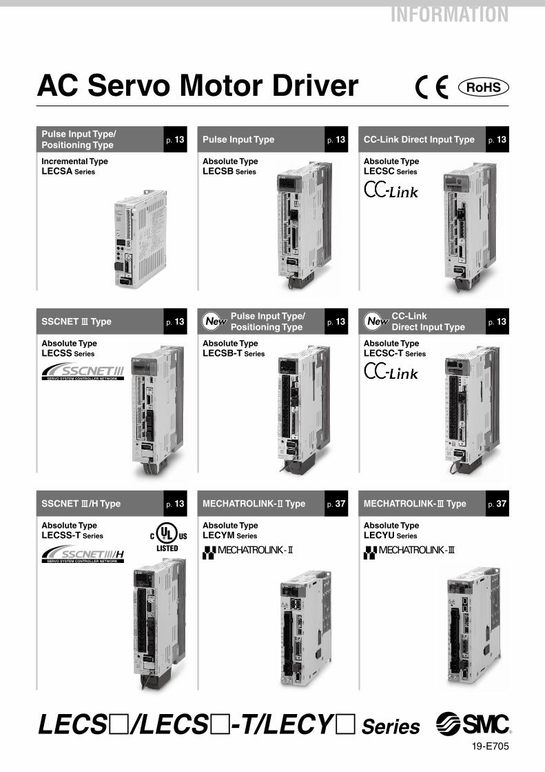
AC Servo Motor Driver
∗1 ∗2Positioning Pulse Synchronous
Networkdirect input
Control method Application/Function
Compatible motor
SeriesSetup
software
Compatible option
100 W 200 W 400 W
LECSA(Pulse input type/Positioning type)
LECSB(Pulse input type)
LECSS (SSCNET# type)Compatible with Mitsubishi Electric’sservo system controller network
LECSC(CC-Link direct input type)
Up to7 points LEC-MRC2
LEC-MRC2
LEC-MRC2
LEC-MRC2
LEC-MRC2
Up to255 points
CC-LinkVer.1.10
SSCNET3 ∗2
∗2
Incr
emen
tal
Type
Ab
solu
te T
ype
LECS/LECS-T/LECY Series List
LECYU
LECYM
LECSS-T (SSCNET#/H type)Compatible with Mitsubishi Electric’sservo system controller network
SigmaWin+™
SigmaWin+™
Pushingoperation∗4
∗4
∗4
∗4
∗3
∗3
MECHATROLINK-3
MECHATROLINK-2
SSCNET3/H
LECSB-T(Pulse input type/Positioning type)
LECSC-T(CC-Link direct input type)
LEC-MRC2Up to
255 pointsCC-LinkVer.1.10
LEC-MRC2Up to
255 points
∗1 For positioning types, the settings need to be changed in order to use the max. set values. Setup software (MR Configurator2™) LEC-MRC2 is required.∗2 Available when a Mitsubishi motion controller is used as the master∗3 Available when a motion controller is used as the master∗4 The LECSB2-T is only applicable when the control method is positioning. The point table is used to set the pushing operation settings.
To set the pushing operation settings, an additional dedicated file (pushing operation extension file) must be downloaded separately to be used with the setup software (MR Configurator2™: LEC-MRC2). Please download this dedicated file from the SMC website: https://www.smcworld.com/When selecting the LECSS or LECSS2-T, combine it with a master station (such as the Simple Motion module manufactured by Mitsubishi Electric Corporation) which has a pushing operation function.
∗ For customer-provided PLC and motion controller setting and usage instructions, confirm with the retailer or manufacturer.
-@
-#
1
Time
Settlingtime Settling
time
TimeS
peed
Spe
ed
LECS/LECS-T/LECY Series
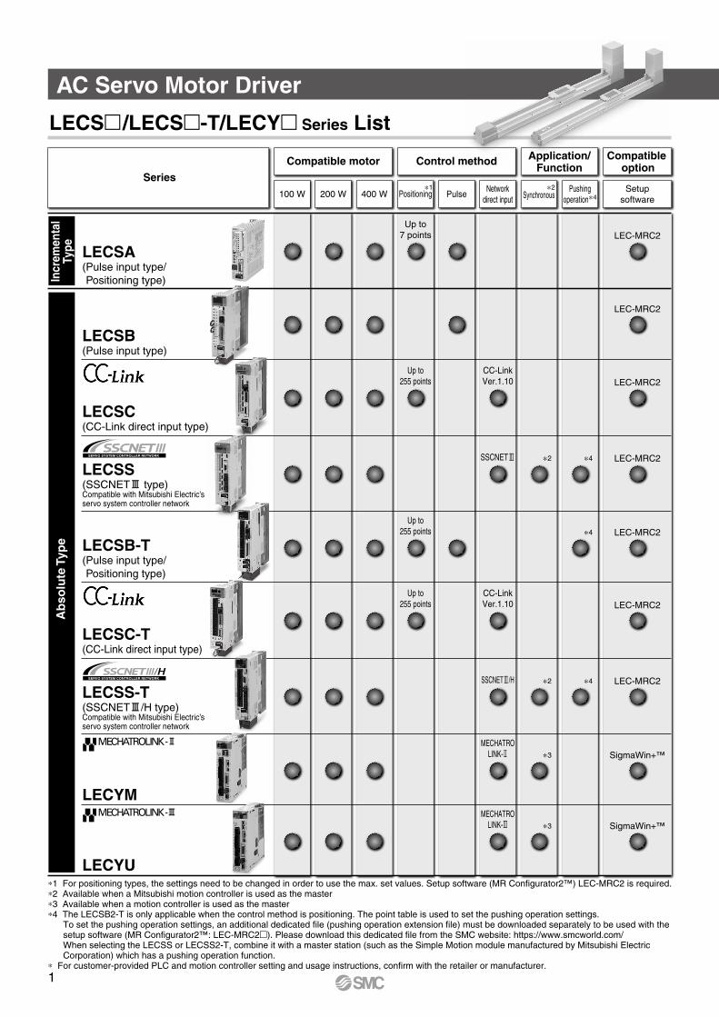
Gain adjustment using auto tuning
Auto-tuning function
Vibration suppression control function
• Controls the difference between the command value and the actual action
• Automatically suppresses low-frequency machine vibrations (1 to 100 Hz)
2
With display setting function
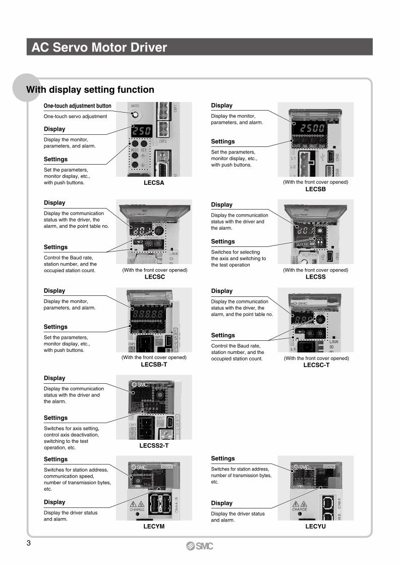
One-touch servo adjustment
One-touch adjustment button
Display the monitor, parameters, and alarm.
Display
Set the parameters, monitor display, etc., with push buttons.
Settings
Display the monitor, parameters, and alarm.
Display
Set the parameters, monitor display, etc., with push buttons.
(With the front cover opened)
Settings
Display the communication status with the driver, the alarm, and the point table no.
Display
Control the Baud rate, station number, and the occupied station count.
Settings
LECSALECSB
Display the communication status with the driver and the alarm.
Display
Switches for selecting the axis and switching to the test operation
(With the front cover opened)
Settings
LECSS(With the front cover opened)
LECSC
(With the front cover opened)LECSC-T
Display the communication status with the driver and the alarm.
Display
Switches for axis setting, control axis deactivation, switching to the test operation, etc.
Settings
LECSS2-T
Display the monitor, parameters, and alarm.
Display
Set the parameters, monitor display, etc., with push buttons.
(With the front cover opened)
Settings
LECSB-T
Display the driver status and alarm.
Display
Display the driver status and alarm.
Display
LECYULECYM
Switches for station address, communication speed, number of transmission bytes, etc.
Settings
Switches for station address, number of transmission bytes, etc.
Settings
AC Servo Motor Driver
Display the communication status with the driver, the alarm, and the point table no.
Display
Control the Baud rate, station number, and the occupied station count.
Settings
3
System Construction
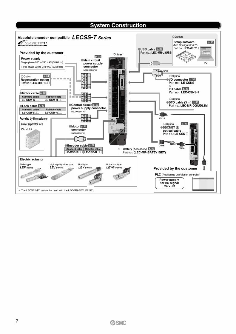
Provided by the customer
Power supply for lock24 VDC
Provided by the customer
Power supply for lock24 VDC
p. 20
p. 20
p. 35
p. 36
p. 32
p. 21
p. 36
p. 35
p. 32
p. 33
p. 36
p. 21
p. 32
p. 34
p. 32
p. 32
p. 21
p. 34
p. 32
p. 32
p. 32
p. 33
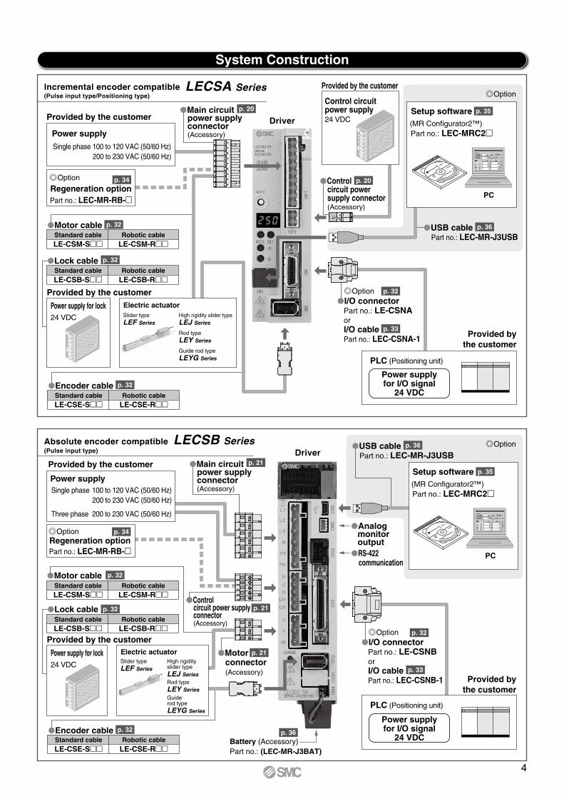
Incremental encoder compatible LECSA Series
Driver
DriverAbsolute encoder compatible LECSB Series
Power supplyfor I/O signal
24 VDC
Power supplySingle phase 100 to 120 VAC (50/60 Hz) 200 to 230 VAC (50/60 Hz)
Provided by the customer
Battery (Accessory)
Part no.: LEC-MR-RB-
Part no.: (LEC-MR-J3BAT)
Provided by the customer
Option
Option
Provided bythe customer
Power supplySingle phase 100 to 120 VAC (50/60 Hz) 200 to 230 VAC (50/60 Hz)
Three phase 200 to 230 VAC (50/60 Hz)
Provided by the customer
Control circuit power supply24 VDC
Option
Regeneration option
Standard cable Robotic cableLE-CSM-S LE-CSM-R
Motor cable
Motor cable
Main circuit power supply connector(Accessory)
Setup software
Setup software
I/O connectorPart no.: LE-CSNAorI/O cablePart no.: LEC-CSNA-1
OptionI/O connector
Part no.: LE-CSNBorI/O cablePart no.: LEC-CSNB-1
USB cablePart no.: LEC-MR-J3USB
USB cablePart no.: LEC-MR-J3USB
Analogmonitor output
RS-422communication
Control circuit power supply connector(Accessory)
Control circuit power supply connector(Accessory)
Motor connector(Accessory)
Standard cable Robotic cableLE-CSB-S LE-CSB-R
Lock cable
Lock cable
Standard cable Robotic cableLE-CSM-S LE-CSM-R
Standard cable Robotic cableLE-CSB-S LE-CSB-R
Standard cable Robotic cableLE-CSE-S LE-CSE-R
Encoder cable
Encoder cable
Provided by the customer
PLC (Positioning unit)
Power supplyfor I/O signal
24 VDC
PLC (Positioning unit)
Standard cable Robotic cableLE-CSE-S LE-CSE-R
(Pulse input type/Positioning type)
(Pulse input type)
Part no.: LEC-MR-RB-
OptionRegeneration option
Main circuit power supplyconnector(Accessory)
PC
(MR Configurator2™)Part no.: LEC-MRC2
PC
(MR Configurator2™)Part no.: LEC-MRC2
Option
Electric actuator
Rod typeLEY Series
Guide rod typeLEYG Series
High rigidity slider typeLEJ Series
Slider typeLEF Series
Electric actuator
Rod typeLEY SeriesGuiderod typeLEYG Series
High rigidityslider typeLEJ Series
Slider typeLEF Series
4
System Construction
Provided by the customer
Power supply for lock24 VDC
Provided by the customer
Power supply for lock24 VDC
p. 21
p. 34
p. 32
p. 32
p. 32
p. 21
p. 21
p. 32
p. 36
p. 35
p. 33
p. 36
p. 21
p. 34
p. 32
p. 32
p. 32
p. 21
p. 21
p. 36
p. 32
p. 36
p. 35
p. 33
p. 33
Driver
PC
Provided bythe customer
Power supplySingle phase 100 to 120 VAC (50/60 Hz) 200 to 230 VAC (50/60 Hz)
Three phase 200 to 230 VAC (50/60 Hz)
Provided by the customer
Standard cable Robotic cableLE-CSM-S LE-CSM-R
Standard cable Robotic cableLE-CSB-S LE-CSB-R
Standard cable Robotic cableLE-CSE-S LE-CSE-R
PLC (CC-Link master unit)
CC-Link connector ∗1
(Accessory)
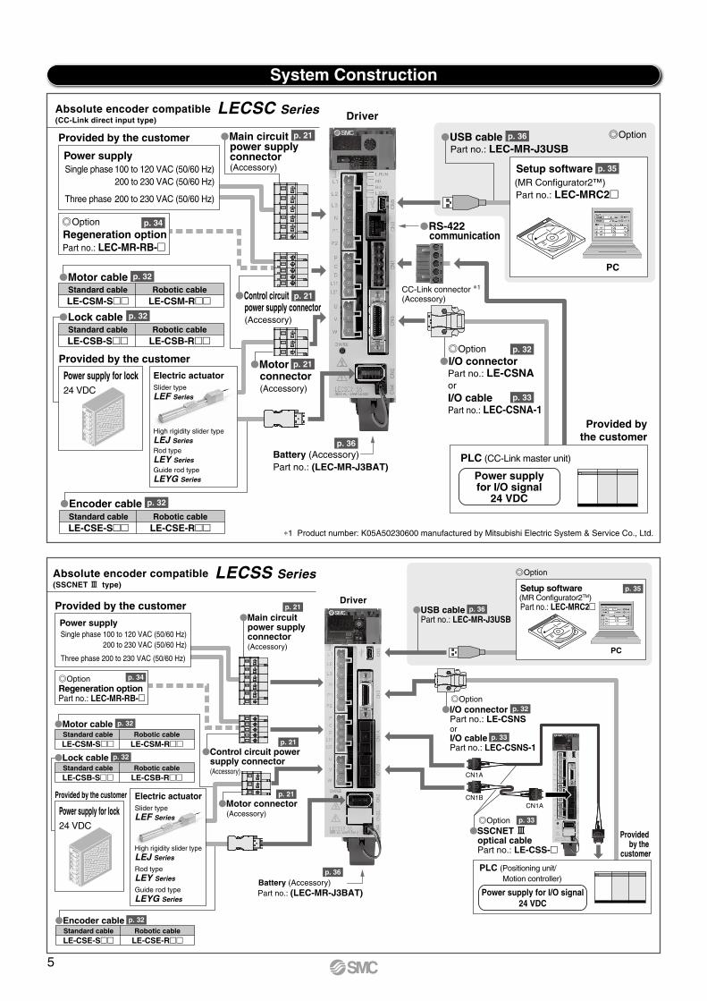
Absolute encoder compatible LECSC Series(CC-Link direct input type)
Part no.: LEC-MR-RB-
OptionRegeneration option
Motor cable
Lock cable
Encoder cable
Main circuit power supplyconnector(Accessory)
Control circuitpower supply connector(Accessory)
Motor connector(Accessory)
Battery (Accessory)Part no.: (LEC-MR-J3BAT)
OptionUSB cablePart no.: LEC-MR-J3USB
Setup software(MR Configurator2™)Part no.: LEC-MRC2
OptionI/O connector
Part no.: LE-CSNAorI/O cablePart no.: LEC-CSNA-1
Power supplyfor I/O signal
24 VDC
RS-422communication
∗1 Product number: K05A50230600 manufactured by Mitsubishi Electric System & Service Co., Ltd.
Driver
Battery (Accessory)
PC
Setup software(MR Configurator2TM)Part no.: LEC-MRC2
Part no.: (LEC-MR-J3BAT)
Option
Provided by the
customer
Power supplySingle phase 100 to 120 VAC (50/60 Hz) 200 to 230 VAC (50/60 Hz)
Three phase 200 to 230 VAC (50/60 Hz)
Provided by the customer
Part no.: LEC-MR-RB-
OptionRegeneration option
Main circuit power supply connector(Accessory)
I/O connectorPart no.: LE-CSNSorI/O cablePart no.: LEC-CSNS-1
USB cablePart no.: LEC-MR-J3USB
Control circuit power supply connector(Accessory)
Motor connector(Accessory)
Standard cable Robotic cableLE-CSM-S LE-CSM-R
Motor cable
Standard cable Robotic cableLE-CSB-S LE-CSB-R
Standard cable Robotic cableLE-CSE-S LE-CSE-R
Lock cable
Encoder cable
Power supply for I/O signal24 VDC
PLC (Positioning unit/Motion controller)
Option
SSCNET #optical cablePart no.: LE-CSS-
Option
CN1ACN1B
CN1A
Absolute encoder compatible LECSS Series(SSCNET # type)
Electric actuator
Rod typeLEY Series
Guide rod typeLEYG Series
High rigidity slider typeLEJ Series
Slider typeLEF Series
Electric actuator
Rod typeLEY SeriesGuide rod typeLEYG Series
High rigidity slider typeLEJ Series
Slider typeLEF Series
5
System Construction
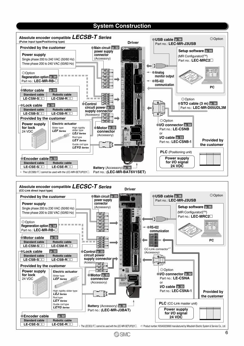
DriverAbsolute encoder compatible LECSB-T Series
Battery (Accessory)
PC
Setup software(MR Configurator2TM)Part no.: LEC-MRC2
Part no.: (LEC-MR-BAT6V1SET)
Provided bythe customer
Power supplySingle phase 200 to 240 VAC (50/60 Hz)Three phase 200 to 240 VAC (50/60 Hz)
Power supplySingle phase 200 to 230 VAC (50/60 Hz)Three phase 200 to 230 VAC (50/60 Hz)
Provided by the customer
Part no.: LEC-MR-RB-
OptionRegeneration option
Main circuit power supply connector(Accessory)
I/O connectorPart no.: LE-CSNBorI/O cablePart no.: LEC-CSNB-1
Analog monitor output
RS-422 communication
USB cablePart no.: LEC-MR-J3USB
Control circuit power supply connector(Accessory)
Motor connector(Accessory)
Standard cable Robotic cableLE-CSM-S LE-CSM-R
Motor cable
Standard cable Robotic cableLE-CSB-S LE-CSB-R
Standard cable Robotic cableLE-CSE-S LE-CSE-R
Lock cable
Encoder cable Power supplyfor I/O signal
24 VDC
PLC (Positioning unit)
(Pulse input type/Positioning type)
Electric actuator
Rod typeLEY Series
Guide rod typeLEYG Series
High rigidity slider typeLEJ Series
Slider typeLEF Series
Provided by the customer
Power supply for lock24 VDC
Driver
PC
Provided by the customer
Part no.: LEC-MR-RB-Regeneration option
Main circuit power supply connector(Accessory)
I/O connectorPart no.: LE-CSNAorI/O cablePart no.: LEC-CSNA-1
RS-422 communication
USB cablePart no.: LEC-MR-J3USB
Control circuit power supply connector(Accessory)
Motor connector(Accessory)
Standard cable Robotic cableLE-CSM-S LE-CSM-R
Motor cable
Standard cable Robotic cableLE-CSB-S LE-CSB-R
Lock cable
PLC (CC-Link master unit)
CC-Link connector∗1
(Accessory)
∗1 Product number: K05A50230600 manufactured by Mitsubishi Electric System & Service Co., Ltd.
Absolute encoder compatible LECSC-T Series(CC-Link direct input type)
Electric actuator
Rod typeLEY SeriesGuide rod typeLEYG Series
High rigidity slider typeLEJ Series
Slider typeLEF Series
Provided by the customer
p. 34
p. 22
p. 22
p. 22
p. 36
p. 33
p. 36
p. 32
p. 35
p. 36
p. 32
p. 32
p. 32
p. 23 p. 36
p. 32
p. 33
p. 34
p. 32
p. 32
p. 32
p. 23
p. 23
∗ The LECSB2-T cannot be used with the LEC-MR-SETUP221.
Battery (Accessory)Part no.: (LEC-MR-J3BAT)
Standard cable Robotic cableLE-CSE-S LE-CSE-R
Encoder cable
p. 36
STO cable (3 m)Part no.: LEC-MR-D05UDL3M
Option
Setup software(MR Configurator2TM)Part no.: LEC-MRC2
p. 35
Option
Option
Option
Option
OptionPower supply for lock24 VDC
∗ The LECSC2-T cannot be used with the LEC-MR-SETUP221.
Provided bythe customer
Power supplyfor I/O signal
24 VDC
6
System Construction
Provided by the customer
Power supply for lock24 VDC
p. 22
p. 34
p. 32
p. 32
p. 36
p. 33
p. 33
p. 32
p. 35
p. 36
p. 36
p. 22
p. 32
p. 22
PC
Setup software(MR Configurator2TM)Part no.: LEC-MRC2
Option
USB cablePart no.: LEC-MR-J3USBDriver
Battery (Accessory)Part no.: (LEC-MR-BAT6V1SET)
Provided by the customer
Power supplySingle phase 200 to 240 VAC (50/60 Hz)
Three phase 200 to 240 VAC (50/60 Hz)
Provided by the customer
Part no.: LEC-MR-RB-
OptionRegeneration option
Main circuit power supply connector(Accessory)
I/O connectorPart no.: LE-CSNSorI/O cablePart no.: LEC-CSNS-1
Control circuit power supply connector(Accessory)
Motor connector(Accessory)
Standard cable Robotic cableLE-CSM-S LE-CSM-R
Motor cable
Standard cable Robotic cableLE-CSB-S LE-CSB-R
Standard cable Robotic cableLE-CSE-S LE-CSE-R
Lock cable
Encoder cable
Power supply for I/O signal
24 VDC
PLC (Positioning unit/Motion controller)
Option
STO cable (3 m)Part no.: LEC-MR-D05UDL3M
Option
SSCNET #optical cablePart no.: LE-CSS-
Option
CN1ACN1B
CN1A
CN3
Absolute encoder compatible LECSS-T Series
Electric actuator
∗ The LECSS2-T cannot be used with the LEC-MR-SETUP221.
Rod typeLEY Series
Guide rod typeLEYG Series
High rigidity slider typeLEJ Series
Slider typeLEF Series
7
System Construction
Standard cable Robotic cableLE-CYE-SA LE-CYE-RA
Encoder cable p. 43
p. 46
Standard cable Robotic cableLE-CYE-SA LE-CYE-RA
Encoder cable p. 43
p. 40
p. 43
p. 43
p. 40
p. 40
p. 45
p. 45
p. 40
p. 40
p. 43
p. 43
p. 40
p. 46
p. 46
p. 44
p. 44
p. 46
p. 44
p. 46
p. 46
p. 44
Part no.: LEC-CYU-
-#cable
Driver
PC
Setup software(SigmaWin+TM)Please download it via our website.
Option
Provided by the customer
Provided by the customer
USB cablePart no.: LEC-JZ-CVUSB
Motorconnector(Accessory)
Standard cable Robotic cableLE-CYM-SA- LE-CYM-RA-
Motor cable
Standard cable Robotic cableLE-CYB-SA- LE-CYB-RA-
Motor cable for lock option
Motorconnector(Accessory)
Cable for safety function device (3 m)Part no.: LEC-JZ-CVSAF
Power supplyfor I/O signal
24 VDC
PLC (Positioning unit/Motion controller)
I/O connectorPart no.: LE-CYNAorI/O cablePart no.: LEC-CSNA-1
Option
Driver
2nd driver
2nd driver
Standard cable Robotic cableLE-CYM-SA- LE-CYM-RA-
Motor cable
PC
Setup software(SigmaWin+TM)Please download it via our website.
Option
Provided by the customer
USB cablePart no.: LEC-JZ-CVUSB
Cable for safety function device (3 m)Part no.: LEC-JZ-CVSAF
Power supplyfor I/O signal
24 VDC
PLC (Positioning unit/Motion controller)
Main circuit power supply connector(Accessory)
Main circuit power supply connector(Accessory)
∗ If an external regenerative resistor is required, it should be provided by the customer.For external regenerative resistor selection, refer to the compatible actuator catalog.
Provided by the customerExternalregenerative resistor
∗ If an external regenerative resistor is required, it should be provided by the customer.For external regenerative resistor selection, refer to the compatible actuator catalog.
Standard cable Robotic cableLE-CYB-SA- LE-CYB-RA-
Motor cable for lock option
I/O connectorPart no.: LE-CYNAorI/O cablePart no.: LEC-CSNA-1
Option
Option
Option
Externalregenerative resistor
Power supplySingle phase 200 to 230 VAC (50/60 Hz)Three phase 200 to 230 VAC (50/60 Hz)
Provided by the customer
Power supplySingle phase 200 to 230 VAC (50/60 Hz)Three phase 200 to 230 VAC (50/60 Hz)
Provided by the customer
Absolute encoder compatible LECYM Series -@ type
Absolute encoder compatible LECYU Series -# type
Electric actuator
High rigidity slider typeLEJ Series
Rod typeLEY/LEYG Series
Slider typeLEF Series
Provided by the customer
Power supply for lock24 VDC
Part no.: LEC-CYM-
-@cable
Electric actuator
High rigidity slider typeLEJ Series
Rod typeLEY/LEYG Series
Slider typeLEF Series
Provided by the customer
Power supply for lock24 VDC
∗ Order the USB cable (Part no.: LEC-JZ-CVUSB) separately to use this software.
∗ Order the USB cable (Part no.: LEC-JZ-CVUSB) separately to use this software.
U
V
W
L1
L2
L3
L1C
L2C
B1/
B2
B3
1
2
U
V
W
L1
L2
L3
L1C
L2C
B1/
B2
B3
1
2
8
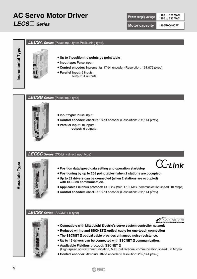
LECSA Series (Pulse input type/ Positioning type)
LECS Series
LECSB Series (Pulse input type)
LECSC Series (CC-Link direct input type)
LECSS Series (SSCNET# type)
Incr
emen
tal T
ype
AC Servo Motor DriverA
bso
lute
Typ
ePower supply voltage 100 to 120 VAC
200 to 230 VAC
Motor capacity 100/200/400 W
Up to 7 positioning points by point table
Input type: Pulse input
Control encoder: Incremental 17-bit encoder (Resolution: 131,072 p/rev)
Parallel input: 6 inputs output: 4 outputs
Input type: Pulse input
Control encoder: Absolute 18-bit encoder (Resolution: 262,144 p/rev)
Parallel input: 10 inputs output: 6 outputs
Position data/speed data setting and operation start/stop
Positioning by up to 255 point tables (when 2 stations are occupied)
Up to 32 drivers can be connected (when 2 stations are occupied) with CC-Link communication.
Applicable Fieldbus protocol: CC-Link (Ver. 1.10, Max. communication speed: 10 Mbps)
Control encoder: Absolute 18-bit encoder (Resolution: 262,144 p/rev)
Compatible with Mitsubishi Electric,s servo system controller network
Reduced wiring and SSCNET#optical cable for one-touch connection
The SSCNET#optical cable provides enhanced noise resistance.
Up to 16 drivers can be connected with SSCNET#communication.
Applicable Fieldbus protocol: SSCNET#(High-speed optical communication, Max. bidirectional communication speed: 50 Mbps)
Control encoder: Absolute 18-bit encoder (Resolution: 262,144 p/rev)
9
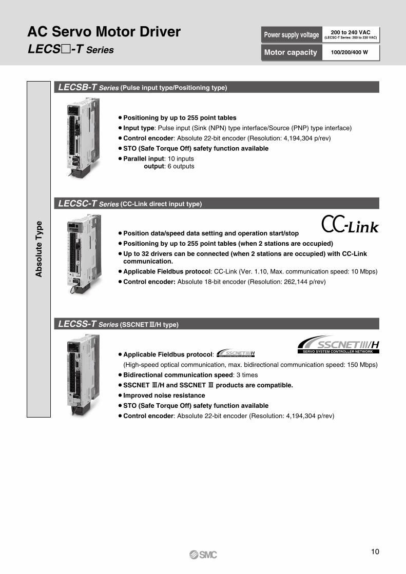
LECS-T Series
AC Servo Motor Driver
LECSB-T Series (Pulse input type/Positioning type)
LECSC-T Series (CC-Link direct input type)
¡Position data/speed data setting and operation start/stop
¡Positioning by up to 255 point tables (when 2 stations are occupied)
¡Up to 32 drivers can be connected (when 2 stations are occupied) with CC-Link communication.
¡Applicable Fieldbus protocol: CC-Link (Ver. 1.10, Max. communication speed: 10 Mbps)
¡Control encoder: Absolute 18-bit encoder (Resolution: 262,144 p/rev)
¡Positioning by up to 255 point tables
¡Input type: Pulse input (Sink (NPN) type interface/Source (PNP) type interface)
¡Control encoder: Absolute 22-bit encoder (Resolution: 4,194,304 p/rev)
¡STO (Safe Torque Off) safety function available
¡Parallel input: 10 inputsoutput: 6 outputs
Ab
solu
te T
ype
LECSS-T Series (SSCNET#/H type)
¡Applicable Fieldbus protocol:
(High-speed optical communication, max. bidirectional communication speed: 150 Mbps)
¡Bidirectional communication speed: 3 times
¡SSCNET #/H and SSCNET # products are compatible.
¡Improved noise resistance
¡STO (Safe Torque Off) safety function available
¡Control encoder: Absolute 22-bit encoder (Resolution: 4,194,304 p/rev)
Power supply voltage 200 to 240 VAC(LECSC-T Series: 200 to 230 VAC)
Motor capacity 100/200/400 W
10
-@
-#
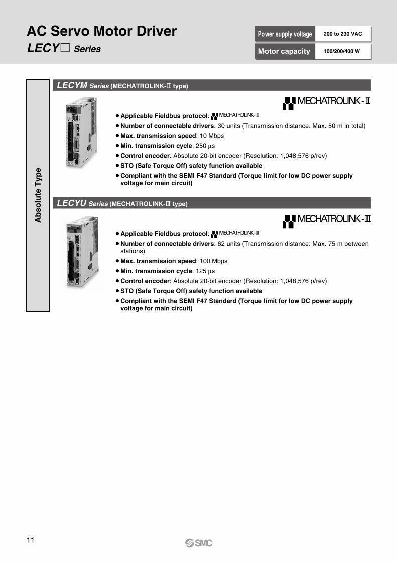
LECY Series
LECYM Series (MECHATROLINK-@ type)
LECYU Series (MECHATROLINK-# type)
¡Applicable Fieldbus protocol:
¡Number of connectable drivers: 30 units (Transmission distance: Max. 50 m in total)
¡Max. transmission speed: 10 Mbps
¡Min. transmission cycle: 250 ms
¡Control encoder: Absolute 20-bit encoder (Resolution: 1,048,576 p/rev)
¡STO (Safe Torque Off) safety function available
¡Compliant with the SEMI F47 Standard (Torque limit for low DC power supply voltage for main circuit)
¡Applicable Fieldbus protocol:
¡Number of connectable drivers: 62 units (Transmission distance: Max. 75 m between stations)
¡Max. transmission speed: 100 Mbps
¡Min. transmission cycle: 125 ms
¡Control encoder: Absolute 20-bit encoder (Resolution: 1,048,576 p/rev)
¡STO (Safe Torque Off) safety function available
¡Compliant with the SEMI F47 Standard (Torque limit for low DC power supply voltage for main circuit)
AC Servo Motor DriverA
bso
lute
Typ
e
-@
-#
Power supply voltage 200 to 230 VAC
Motor capacity 100/200/400 W
11
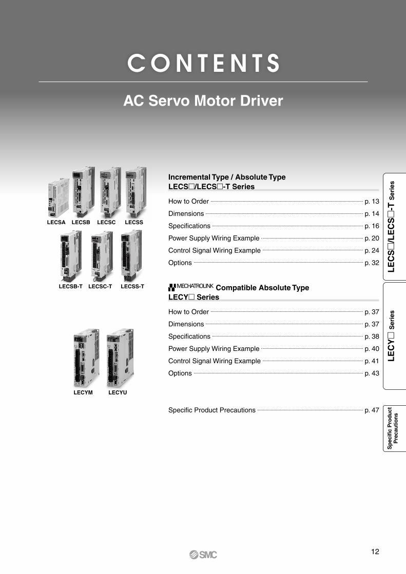
C O N T E N T S
Incremental Type / Absolute TypeLECS/LECS-T Series
How to Order p. 13
Dimensions p. 14
Specifications p. 16
Power Supply Wiring Example p. 20
Control Signal Wiring Example p. 24
Options p. 32
Compatible Absolute Type LECY Series
How to Order p. 37
Dimensions p. 37
Specifications p. 38
Power Supply Wiring Example p. 40
Control Signal Wiring Example p. 41
Options p. 43
Specific Product Precautions p. 47
LECSA LECSB
LECSB-T
LECSC
LECSC-T
LECSS
LECSS-T
LECYM LECYU
AC Servo Motor Driver
12
LE
CS
/L
EC
S
-T S
erie
sL
EC
Y
Ser
ies
Sp
ecifi
c P
rodu
ctP
reca
utio
ns
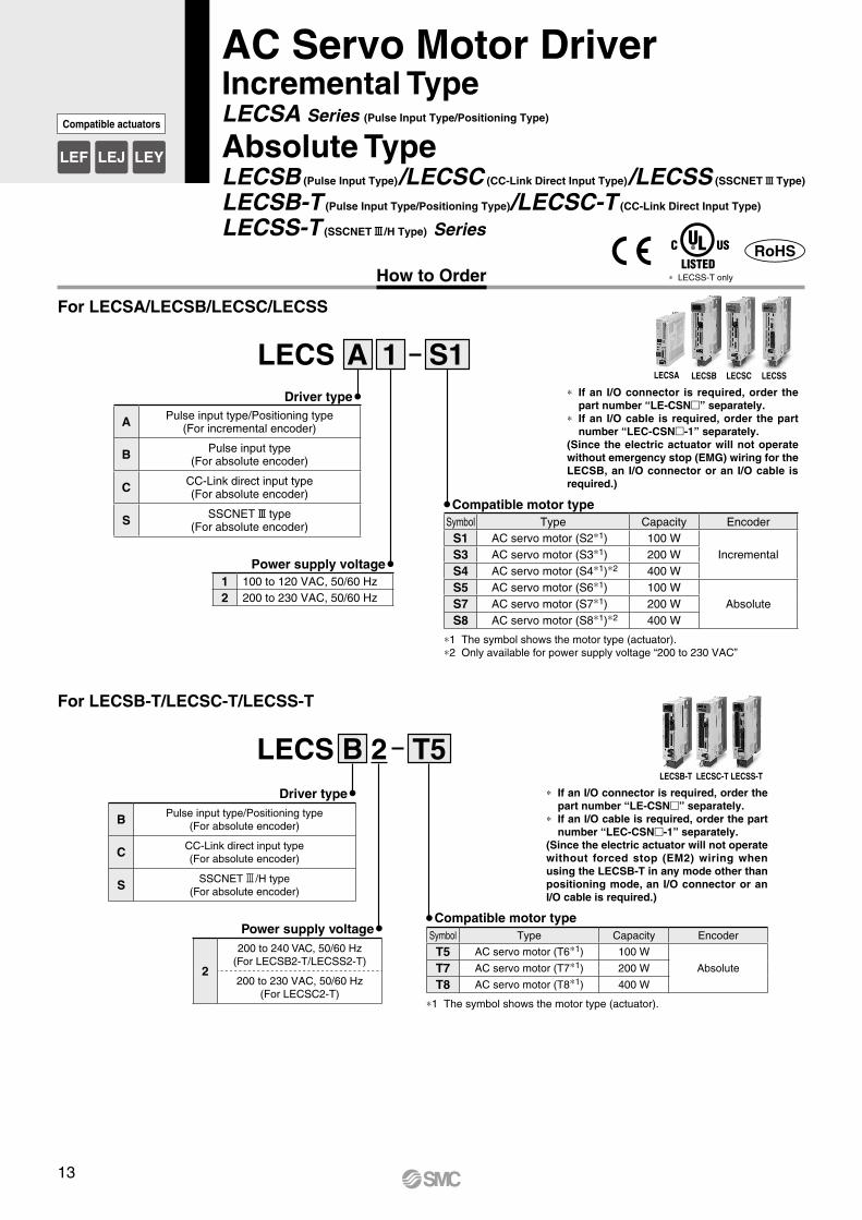
How to Order
LECS 1A S1
Compatible motor type
Power supply voltage
Driver type
AC Servo Motor DriverIncremental TypeLECSA Series (Pulse Input Type/Positioning Type)
Absolute TypeLECSB (Pulse Input Type)/LECSC (CC-Link Direct Input Type)/LECSS (SSCNET#Type)
LECSB-T (Pulse Input Type/Positioning Type)/LECSC-T (CC-Link Direct Input Type)
LECSS-T (SSCNET#/H Type) Series
LECSA LECSB
LECSB-T
LECSC
LECSC-T
LECSS
LECSS-T
LECS T52Driver type
B Pulse input type/Positioning type(For absolute encoder)
C CC-Link direct input type(For absolute encoder)
S SSCNET3/H type(For absolute encoder)
Power supply voltage
2
200 to 240 VAC, 50/60 Hz(For LECSB2-T/LECSS2-T)
200 to 230 VAC, 50/60 Hz(For LECSC2-T)
For LECSA/LECSB/LECSC/LECSS
For LECSB-T/LECSC-T/LECSS-T
* If an I/O connector is required, order the part number “LE-CSN” separately.
* If an I/O cable is required, order the part number “LEC-CSN-1” separately.
(Since the electric actuator will not operate without emergency stop (EMG) wiring for the LECSB, an I/O connector or an I/O cable is required.)
* If an I/O connector is required, order the part number “LE-CSN” separately.
* If an I/O cable is required, order the part number “LEC-CSN-1” separately.
(Since the electric actuator will not operate without forced stop (EM2) wiring when using the LECSB-T in any mode other than positioning mode, an I/O connector or an I/O cable is required.)
B
1 100 to 120 VAC, 50/60 Hz2 200 to 230 VAC, 50/60 Hz
A Pulse input type/Positioning type(For incremental encoder)
B Pulse input type(For absolute encoder)
C CC-Link direct input type(For absolute encoder)
S SSCNET# type(For absolute encoder) Symbol Type Capacity Encoder
S1 AC servo motor (S2*1) 100 WIncrementalS3 AC servo motor (S3*1) 200 W
S4 AC servo motor (S4*1)*2 400 WS5 AC servo motor (S6*1) 100 W
AbsoluteS7 AC servo motor (S7*1) 200 WS8 AC servo motor (S8*1)*2 400 W
*1 The symbol shows the motor type (actuator).*2 Only available for power supply voltage “200 to 230 VAC”
Compatible motor typeSymbol Type Capacity Encoder
T5 AC servo motor (T6*1) 100 W
AbsoluteT7 AC servo motor (T7*1) 200 W
T8 AC servo motor (T8*1) 400 W
*1 The symbol shows the motor type (actuator).
13
LEF LEJ LEY
Compatible actuators
* LECSS-T only
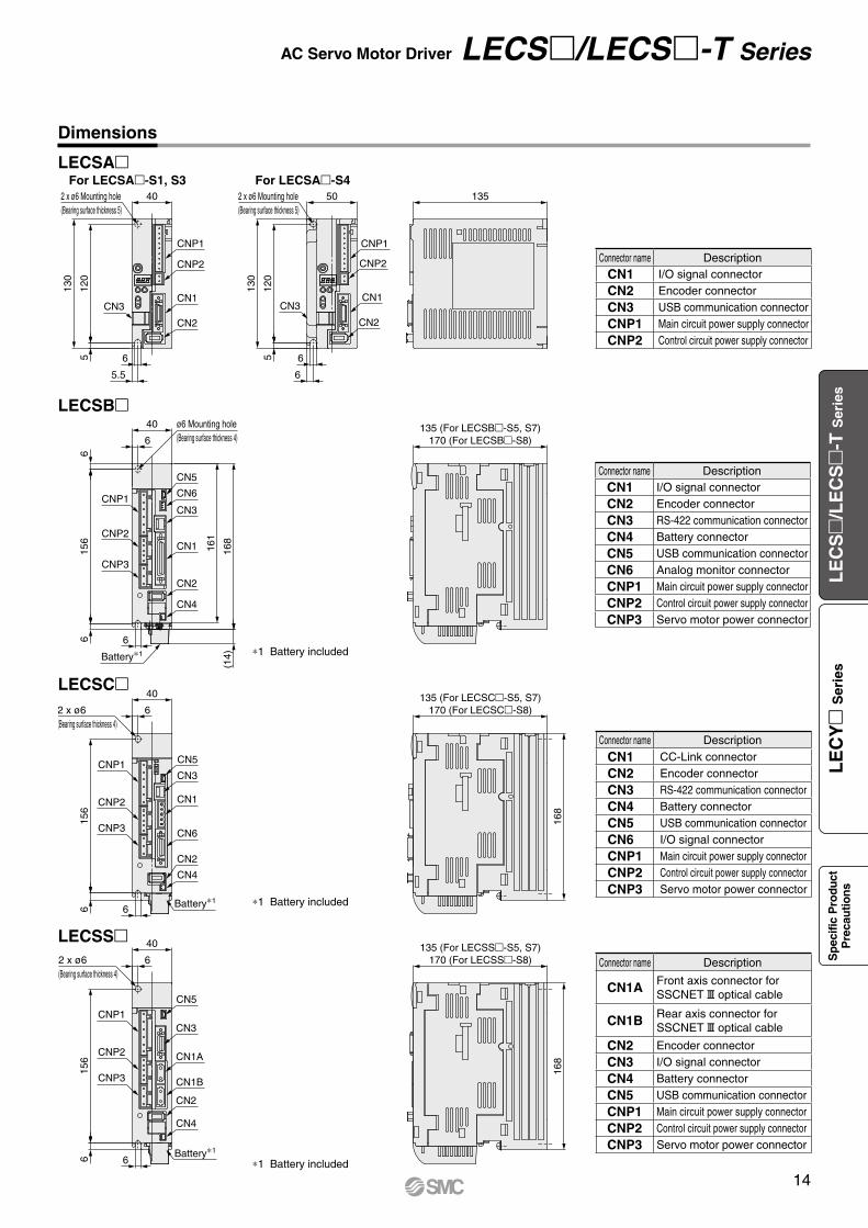
For LECSA-S1, S3 For LECSA-S42 x ø6 Mounting hole(Bearing surface thickness 5)
40
CNP1
CNP2
CN1CN3
CN2
6
5.5
512
0
130
2 x ø6 Mounting hole(Bearing surface thickness 5)
50
CNP1
CNP2
CN1
CN2
CN3
120
130
5 6
6
135
40
6
168
161
CN5
CN6
CN3
CN1
CN2
CN4
CNP1
CNP2
CNP3
156
6 6
Battery∗1
(14)
168
40
62 x ø6(Bearing surface thickness 4)
CNP1
CNP2
CNP3
156
CN5
CN3
CN1
CN6
CN2
CN4
Battery∗166
168
40
62 x ø6(Bearing surface thickness 4)
CN5
CN3
CN1A
CN1B
CN2
CN4
Battery∗1
6
CNP3
CNP2
CNP1
156
66
135 (For LECSB-S5, S7)170 (For LECSB-S8)
135 (For LECSC-S5, S7)170 (For LECSC-S8)
135 (For LECSS-S5, S7)170 (For LECSS-S8)
ø6 Mounting hole(Bearing surface thickness 4)
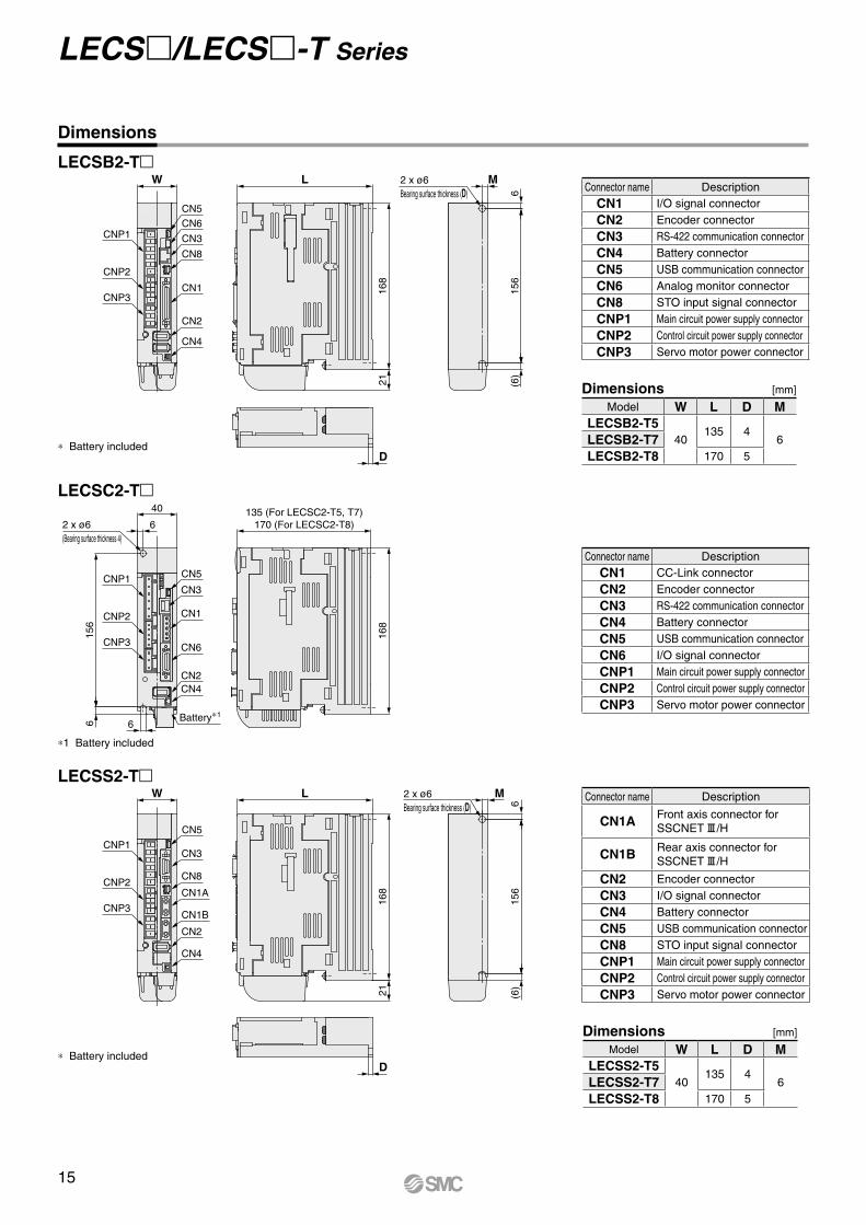
Connector name Description
CN1 I/O signal connector
CN2 Encoder connector
CN3 RS-422 communication connector
CN4 Battery connector
CN5 USB communication connector
CN6 Analog monitor connector
CNP1 Main circuit power supply connector
CNP2 Control circuit power supply connector
CNP3 Servo motor power connector
Connector name Description
CN1 I/O signal connector
CN2 Encoder connector
CN3 USB communication connector
CNP1 Main circuit power supply connector
CNP2 Control circuit power supply connector
Connector name Description
CN1A Front axis connector forSSCNET#optical cable
CN1B Rear axis connector forSSCNET#optical cable
CN2 Encoder connector
CN3 I/O signal connector
CN4 Battery connector
CN5 USB communication connector
CNP1 Main circuit power supply connector
CNP2 Control circuit power supply connector
CNP3 Servo motor power connector
Connector name Description
CN1 CC-Link connector
CN2 Encoder connector
CN3 RS-422 communication connector
CN4 Battery connector
CN5 USB communication connector
CN6 I/O signal connector
CNP1 Main circuit power supply connector
CNP2 Control circuit power supply connector
CNP3 Servo motor power connector
LECSA
LECSB
LECSC
LECSS
*1 Battery included
*1 Battery included
*1 Battery included
Dimensions
AC Servo Motor Driver LECS/LECS-T Series
14
LE
CS
/L
EC
S
-T S
erie
sL
EC
Y
Ser
ies
Sp
ecifi
c P
rodu
ctP
reca
utio
ns
W
CNP1
CNP2
CNP3
L
168
21
2 x ø6Bearing surface thickness (D)
M
615
6(6
)
D
135 (For LECSC2-T5, T7)170 (For LECSC2-T8)
168
40
62 x ø6(Bearing surface thickness 4)
CN5
CN5CN6
CN3
CN8
CN1
CN2
CN4
CN3
CN1
CN6
CN2CN4
Battery∗1
6
CNP3
CNP2
CNP1
156
6
LW
CN5
CN3
CN8
CN1A
CN1B
CN2
CN4
CNP3
CNP2
CNP1
168
21
2 x ø6Bearing surface thickness (D)
M
615
6(6
)
D
* Battery included
* Battery included
LECSB2-T
LECSS2-T
Dimensions [mm]
Model W L D MLECSB2-T5
40135 4
6LECSB2-T7LECSB2-T8 170 5
Dimensions
LECSC2-T
*1 Battery included
Connector name Description
CN1 CC-Link connector
CN2 Encoder connector
CN3 RS-422 communication connector
CN4 Battery connector
CN5 USB communication connector
CN6 I/O signal connector
CNP1 Main circuit power supply connector
CNP2 Control circuit power supply connector
CNP3 Servo motor power connector
Connector name Description
CN1 I/O signal connector
CN2 Encoder connector
CN3 RS-422 communication connector
CN4 Battery connector
CN5 USB communication connector
CN6 Analog monitor connector
CN8 STO input signal connector
CNP1 Main circuit power supply connector
CNP2 Control circuit power supply connector
CNP3 Servo motor power connector
Connector name Description
CN1A Front axis connector for SSCNET#/H
CN1B Rear axis connector for SSCNET#/H
CN2 Encoder connector
CN3 I/O signal connector
CN4 Battery connector
CN5 USB communication connector
CN8 STO input signal connector
CNP1 Main circuit power supply connector
CNP2 Control circuit power supply connector
CNP3 Servo motor power connector
Dimensions [mm]
Model W L D MLECSS2-T5
40135 4
6LECSS2-T7LECSS2-T8 170 5
LECS/LECS-T Series
15
Specifications
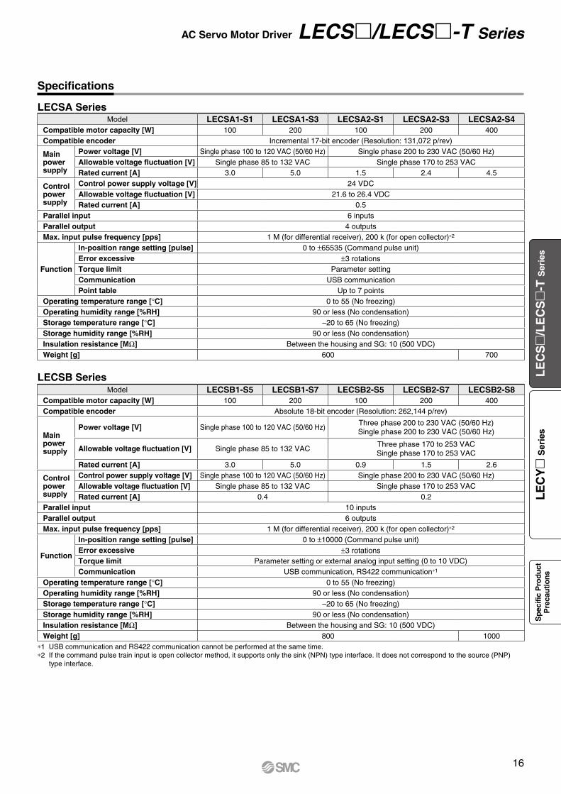
LECSA Series
LECSB Series
*1 USB communication and RS422 communication cannot be performed at the same time.*2 If the command pulse train input is open collector method, it supports only the sink (NPN) type interface. It does not correspond to the source (PNP)
type interface.
Model LECSA1-S1 LECSA1-S3 LECSA2-S1 LECSA2-S3 LECSA2-S4Compatible motor capacity [W] 100 200 100 200 400Compatible encoder Incremental 17-bit encoder (Resolution: 131,072 p/rev)
Main power supply
Power voltage [V] Single phase 100 to 120 VAC (50/60 Hz) Single phase 200 to 230 VAC (50/60 Hz)Allowable voltage fluctuation [V] Single phase 85 to 132 VAC Single phase 170 to 253 VACRated current [A] 3.0 5.0 1.5 2.4 4.5
Control power supply
Control power supply voltage [V] 24 VDCAllowable voltage fluctuation [V] 21.6 to 26.4 VDCRated current [A] 0.5
Parallel input 6 inputsParallel output 4 outputsMax. input pulse frequency [pps] 1 M (for differential receiver), 200 k (for open collector)*2
Function
In-position range setting [pulse] 0 to ±65535 (Command pulse unit)Error excessive ±3 rotationsTorque limit Parameter settingCommunication USB communicationPoint table Up to 7 points
Operating temperature range [°C] 0 to 55 (No freezing)Operating humidity range [%RH] 90 or less (No condensation)Storage temperature range [°C] –20 to 65 (No freezing)Storage humidity range [%RH] 90 or less (No condensation)Insulation resistance [MΩ] Between the housing and SG: 10 (500 VDC)Weight [g] 600 700
Model LECSB1-S5 LECSB1-S7 LECSB2-S5 LECSB2-S7 LECSB2-S8Compatible motor capacity [W] 100 200 100 200 400Compatible encoder Absolute 18-bit encoder (Resolution: 262,144 p/rev)
Main power supply
Power voltage [V] Single phase 100 to 120 VAC (50/60 Hz)Three phase 200 to 230 VAC (50/60 Hz)Single phase 200 to 230 VAC (50/60 Hz)
Allowable voltage fluctuation [V] Single phase 85 to 132 VACThree phase 170 to 253 VACSingle phase 170 to 253 VAC
Rated current [A] 3.0 5.0 0.9 1.5 2.6
Control power supply
Control power supply voltage [V] Single phase 100 to 120 VAC (50/60 Hz) Single phase 200 to 230 VAC (50/60 Hz) Allowable voltage fluctuation [V] Single phase 85 to 132 VAC Single phase 170 to 253 VAC Rated current [A] 0.4 0.2
Parallel input 10 inputsParallel output 6 outputsMax. input pulse frequency [pps] 1 M (for differential receiver), 200 k (for open collector)*2
Function
In-position range setting [pulse] 0 to ±10000 (Command pulse unit)Error excessive ±3 rotationsTorque limit Parameter setting or external analog input setting (0 to 10 VDC)Communication USB communication, RS422 communication*1
Operating temperature range [°C] 0 to 55 (No freezing)Operating humidity range [%RH] 90 or less (No condensation)Storage temperature range [°C] –20 to 65 (No freezing)Storage humidity range [%RH] 90 or less (No condensation)Insulation resistance [MΩ] Between the housing and SG: 10 (500 VDC)Weight [g] 800 1000
AC Servo Motor Driver LECS/LECS-T Series
16
LE
CS
/L
EC
S
-T S
erie
sL
EC
Y
Ser
ies
Sp
ecifi
c P
rodu
ctP
reca
utio
ns
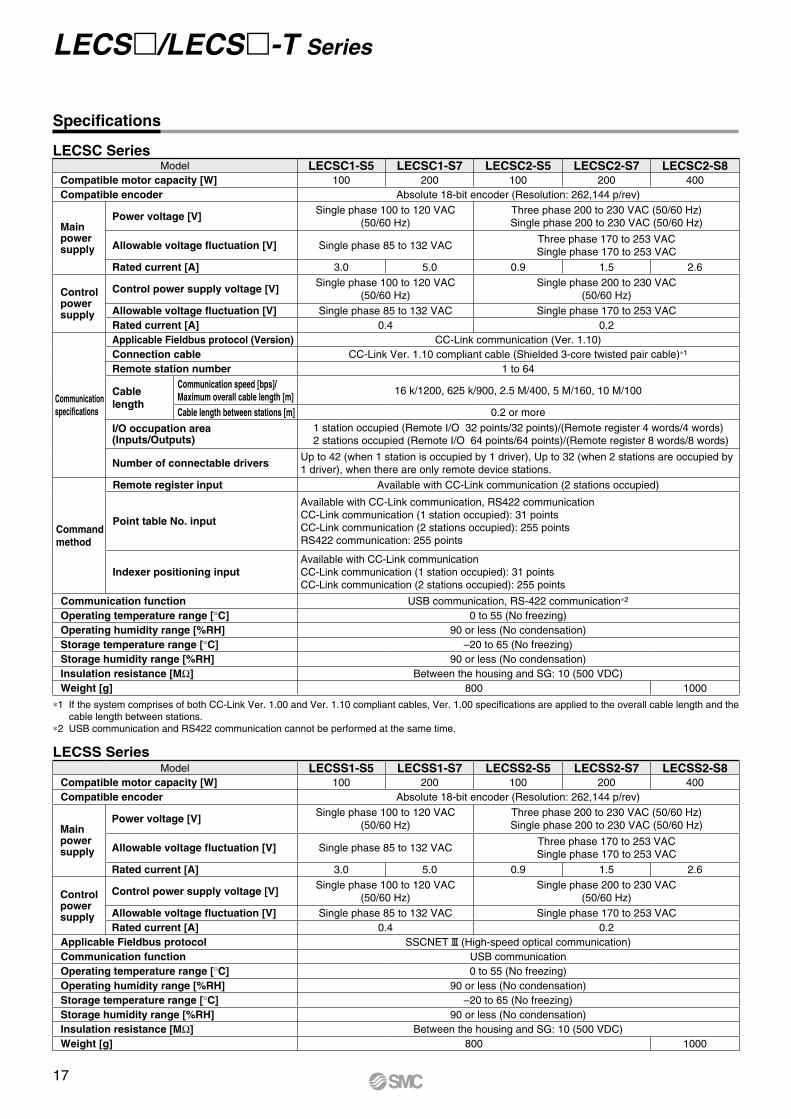
LECSC Series
*1 If the system comprises of both CC-Link Ver. 1.00 and Ver. 1.10 compliant cables, Ver. 1.00 specifications are applied to the overall cable length and the cable length between stations.
*2 USB communication and RS422 communication cannot be performed at the same time.
Specifications
LECSS SeriesModel LECSS1-S5 LECSS1-S7 LECSS2-S5 LECSS2-S7 LECSS2-S8
Compatible motor capacity [W] 100 200 100 200 400Compatible encoder Absolute 18-bit encoder (Resolution: 262,144 p/rev)
Main power supply
Power voltage [V]Single phase 100 to 120 VAC
(50/60 Hz)Three phase 200 to 230 VAC (50/60 Hz)Single phase 200 to 230 VAC (50/60 Hz)
Allowable voltage fluctuation [V] Single phase 85 to 132 VACThree phase 170 to 253 VACSingle phase 170 to 253 VAC
Rated current [A] 3.0 5.0 0.9 1.5 2.6
Control power supply
Control power supply voltage [V]Single phase 100 to 120 VAC
(50/60 Hz)Single phase 200 to 230 VAC
(50/60 Hz)
Allowable voltage fluctuation [V] Single phase 85 to 132 VAC Single phase 170 to 253 VAC Rated current [A] 0.4 0.2
Applicable Fieldbus protocol SSCNET# (High-speed optical communication)Communication function USB communicationOperating temperature range [°C] 0 to 55 (No freezing)Operating humidity range [%RH] 90 or less (No condensation)Storage temperature range [°C] –20 to 65 (No freezing)Storage humidity range [%RH] 90 or less (No condensation)Insulation resistance [MΩ] Between the housing and SG: 10 (500 VDC)Weight [g] 800 1000
Model LECSC1-S5 LECSC1-S7 LECSC2-S5 LECSC2-S7 LECSC2-S8Compatible motor capacity [W] 100 200 100 200 400Compatible encoder Absolute 18-bit encoder (Resolution: 262,144 p/rev)
Main power supply
Power voltage [V]Single phase 100 to 120 VAC
(50/60 Hz)Three phase 200 to 230 VAC (50/60 Hz)Single phase 200 to 230 VAC (50/60 Hz)
Allowable voltage fluctuation [V] Single phase 85 to 132 VACThree phase 170 to 253 VACSingle phase 170 to 253 VAC
Rated current [A] 3.0 5.0 0.9 1.5 2.6
Control power supply
Control power supply voltage [V]Single phase 100 to 120 VAC
(50/60 Hz)Single phase 200 to 230 VAC
(50/60 Hz)
Allowable voltage fluctuation [V] Single phase 85 to 132 VAC Single phase 170 to 253 VAC Rated current [A] 0.4 0.2
Communication specifications
Applicable Fieldbus protocol (Version) CC-Link communication (Ver. 1.10)Connection cable CC-Link Ver. 1.10 compliant cable (Shielded 3-core twisted pair cable)*1
Remote station number 1 to 64
Cablelength
Communication speed [bps]/Maximum overall cable length [m]
16 k/1200, 625 k/900, 2.5 M/400, 5 M/160, 10 M/100
Cable length between stations [m] 0.2 or more
I/O occupation area (Inputs/Outputs)
1 station occupied (Remote I/O 32 points/32 points)/(Remote register 4 words/4 words)2 stations occupied (Remote I/O 64 points/64 points)/(Remote register 8 words/8 words)
Number of connectable driversUp to 42 (when 1 station is occupied by 1 driver), Up to 32 (when 2 stations are occupied by1 driver), when there are only remote device stations.
Command method
Remote register input Available with CC-Link communication (2 stations occupied)
Point table No. input
Available with CC-Link communication, RS422 communicationCC-Link communication (1 station occupied): 31 pointsCC-Link communication (2 stations occupied): 255 pointsRS422 communication: 255 points
Indexer positioning inputAvailable with CC-Link communicationCC-Link communication (1 station occupied): 31 pointsCC-Link communication (2 stations occupied): 255 points
Communication function USB communication, RS-422 communication*2
Operating temperature range [°C] 0 to 55 (No freezing)Operating humidity range [%RH] 90 or less (No condensation)Storage temperature range [°C] –20 to 65 (No freezing)Storage humidity range [%RH] 90 or less (No condensation)Insulation resistance [MΩ] Between the housing and SG: 10 (500 VDC)Weight [g] 800 1000
LECS/LECS-T Series
17
*1 USB communication and RS422 communication cannot be performed at the same time.
LECSC-T Series
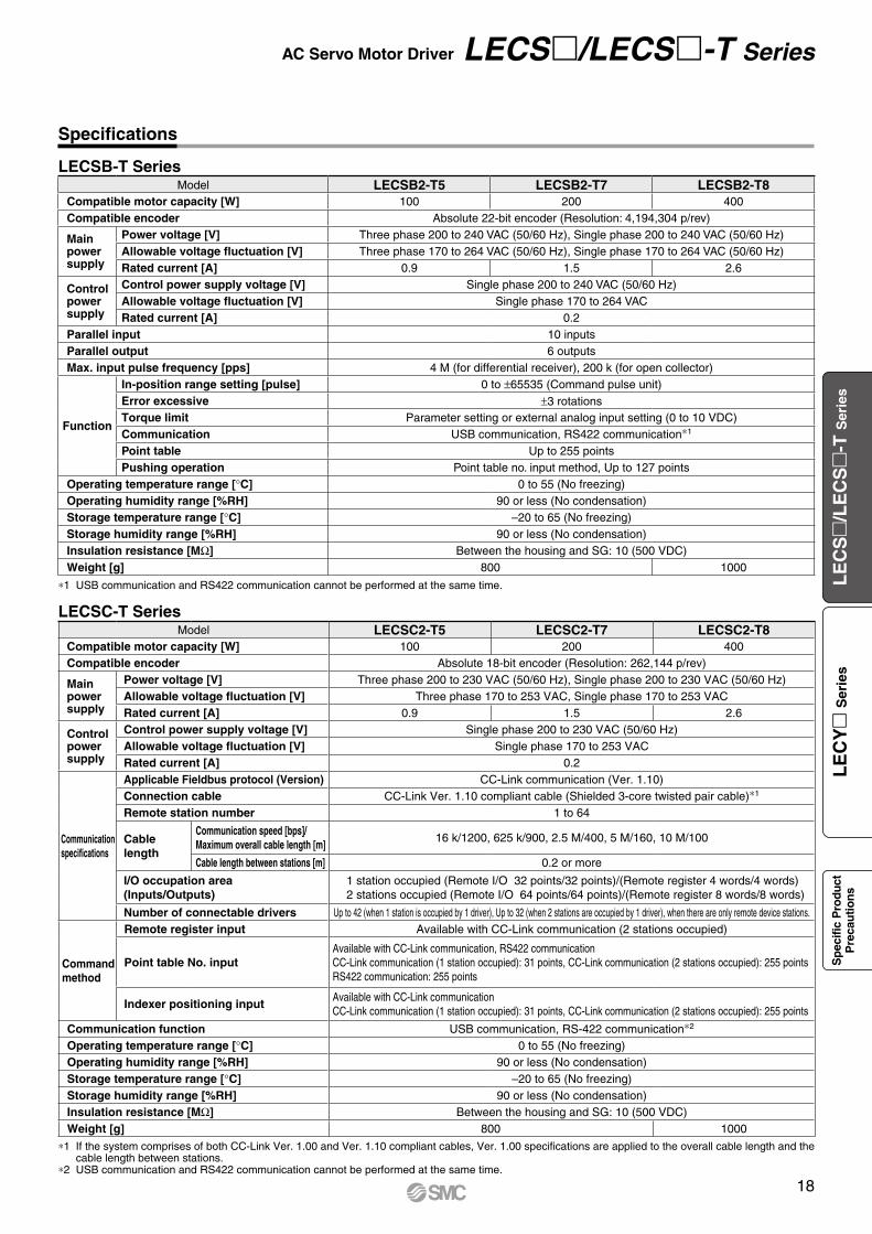
*1 If the system comprises of both CC-Link Ver. 1.00 and Ver. 1.10 compliant cables, Ver. 1.00 specifications are applied to the overall cable length and the cable length between stations.
*2 USB communication and RS422 communication cannot be performed at the same time.
Model LECSC2-T5 LECSC2-T7 LECSC2-T8Compatible motor capacity [W] 100 200 400Compatible encoder Absolute 18-bit encoder (Resolution: 262,144 p/rev)
Main power supply
Power voltage [V] Three phase 200 to 230 VAC (50/60 Hz), Single phase 200 to 230 VAC (50/60 Hz)Allowable voltage fluctuation [V] Three phase 170 to 253 VAC, Single phase 170 to 253 VACRated current [A] 0.9 1.5 2.6
Control power supply
Control power supply voltage [V] Single phase 200 to 230 VAC (50/60 Hz)Allowable voltage fluctuation [V] Single phase 170 to 253 VAC Rated current [A] 0.2
Communication specifications
Applicable Fieldbus protocol (Version) CC-Link communication (Ver. 1.10)Connection cable CC-Link Ver. 1.10 compliant cable (Shielded 3-core twisted pair cable)*1
Remote station number 1 to 64
Cablelength
Communication speed [bps]/Maximum overall cable length [m]
16 k/1200, 625 k/900, 2.5 M/400, 5 M/160, 10 M/100
Cable length between stations [m] 0.2 or more
I/O occupation area (Inputs/Outputs)
1 station occupied (Remote I/O 32 points/32 points)/(Remote register 4 words/4 words)2 stations occupied (Remote I/O 64 points/64 points)/(Remote register 8 words/8 words)
Number of connectable drivers Up to 42 (when 1 station is occupied by 1 driver), Up to 32 (when 2 stations are occupied by 1 driver), when there are only remote device stations.
Command method
Remote register input Available with CC-Link communication (2 stations occupied)
Point table No. inputAvailable with CC-Link communication, RS422 communicationCC-Link communication (1 station occupied): 31 points, CC-Link communication (2 stations occupied): 255 pointsRS422 communication: 255 points
Indexer positioning inputAvailable with CC-Link communicationCC-Link communication (1 station occupied): 31 points, CC-Link communication (2 stations occupied): 255 points
Communication function USB communication, RS-422 communication*2
Operating temperature range [°C] 0 to 55 (No freezing)Operating humidity range [%RH] 90 or less (No condensation)Storage temperature range [°C] –20 to 65 (No freezing)Storage humidity range [%RH] 90 or less (No condensation)Insulation resistance [MΩ] Between the housing and SG: 10 (500 VDC)Weight [g] 800 1000
Specifications
LECSB-T SeriesModel LECSB2-T5 LECSB2-T7 LECSB2-T8
Compatible motor capacity [W] 100 200 400Compatible encoder Absolute 22-bit encoder (Resolution: 4,194,304 p/rev)
Main power supply
Power voltage [V] Three phase 200 to 240 VAC (50/60 Hz), Single phase 200 to 240 VAC (50/60 Hz)Allowable voltage fluctuation [V] Three phase 170 to 264 VAC (50/60 Hz), Single phase 170 to 264 VAC (50/60 Hz)Rated current [A] 0.9 1.5 2.6
Control power supply
Control power supply voltage [V] Single phase 200 to 240 VAC (50/60 Hz)Allowable voltage fluctuation [V] Single phase 170 to 264 VACRated current [A] 0.2
Parallel input 10 inputsParallel output 6 outputsMax. input pulse frequency [pps] 4 M (for differential receiver), 200 k (for open collector)
Function
In-position range setting [pulse] 0 to ±65535 (Command pulse unit)Error excessive ±3 rotationsTorque limit Parameter setting or external analog input setting (0 to 10 VDC)Communication USB communication, RS422 communication*1
Point table Up to 255 pointsPushing operation Point table no. input method, Up to 127 points
Operating temperature range [°C] 0 to 55 (No freezing)Operating humidity range [%RH] 90 or less (No condensation)Storage temperature range [°C] –20 to 65 (No freezing)Storage humidity range [%RH] 90 or less (No condensation)Insulation resistance [MΩ] Between the housing and SG: 10 (500 VDC)Weight [g] 800 1000
18
AC Servo Motor Driver LECS/LECS-T Series
LE
CS
/L
EC
S
-T S
erie
sL
EC
Y
Ser
ies
Sp
ecifi
c P
rodu
ctP
reca
utio
ns
LECSS-T Series
Specifications
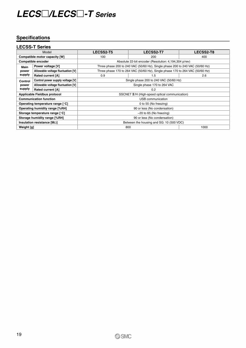
Model LECSS2-T5 LECSS2-T7 LECSS2-T8Compatible motor capacity [W] 100 200 400
Compatible encoder Absolute 22-bit encoder (Resolution: 4,194,304 p/rev)
Main power supply
Power voltage [V] Three phase 200 to 240 VAC (50/60 Hz), Single phase 200 to 240 VAC (50/60 Hz)
Allowable voltage fluctuation [V] Three phase 170 to 264 VAC (50/60 Hz), Single phase 170 to 264 VAC (50/60 Hz)
Rated current [A] 0.9 1.5 2.6
Control power supply
Control power supply voltage [V] Single phase 200 to 240 VAC (50/60 Hz)
Allowable voltage fluctuation [V] Single phase 170 to 264 VAC
Rated current [A] 0.2
Applicable Fieldbus protocol SSCNET#/H (High-speed optical communication)
Communication function USB communication
Operating temperature range [°C] 0 to 55 (No freezing)
Operating humidity range [%RH] 90 or less (No condensation)
Storage temperature range [°C] −20 to 65 (No freezing)
Storage humidity range [%RH] 90 or less (No condensation)
Insulation resistance [MW] Between the housing and SG: 10 (500 VDC)
Weight [g] 800 1000
19
LECS/LECS-T Series
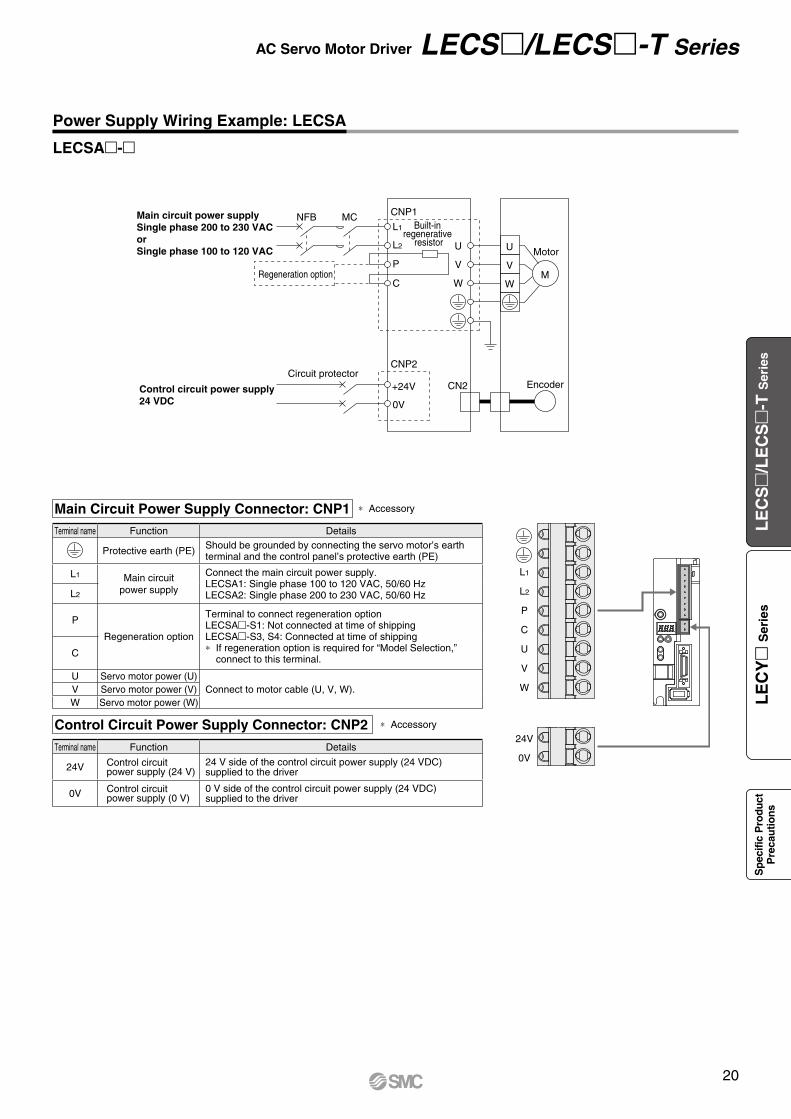
Main circuit power supplySingle phase 200 to 230 VACorSingle phase 100 to 120 VAC
Control circuit power supply24 VDC
L1
CNP1NFB MCBuilt-in
regenerative resistor
Regeneration option
CN2
L2
P
U
V
W
U MotorV
WM
C
+24V
CNP2
0V
EncoderCircuit protector
L1
L2
P
C
U
V
W
24V
0V
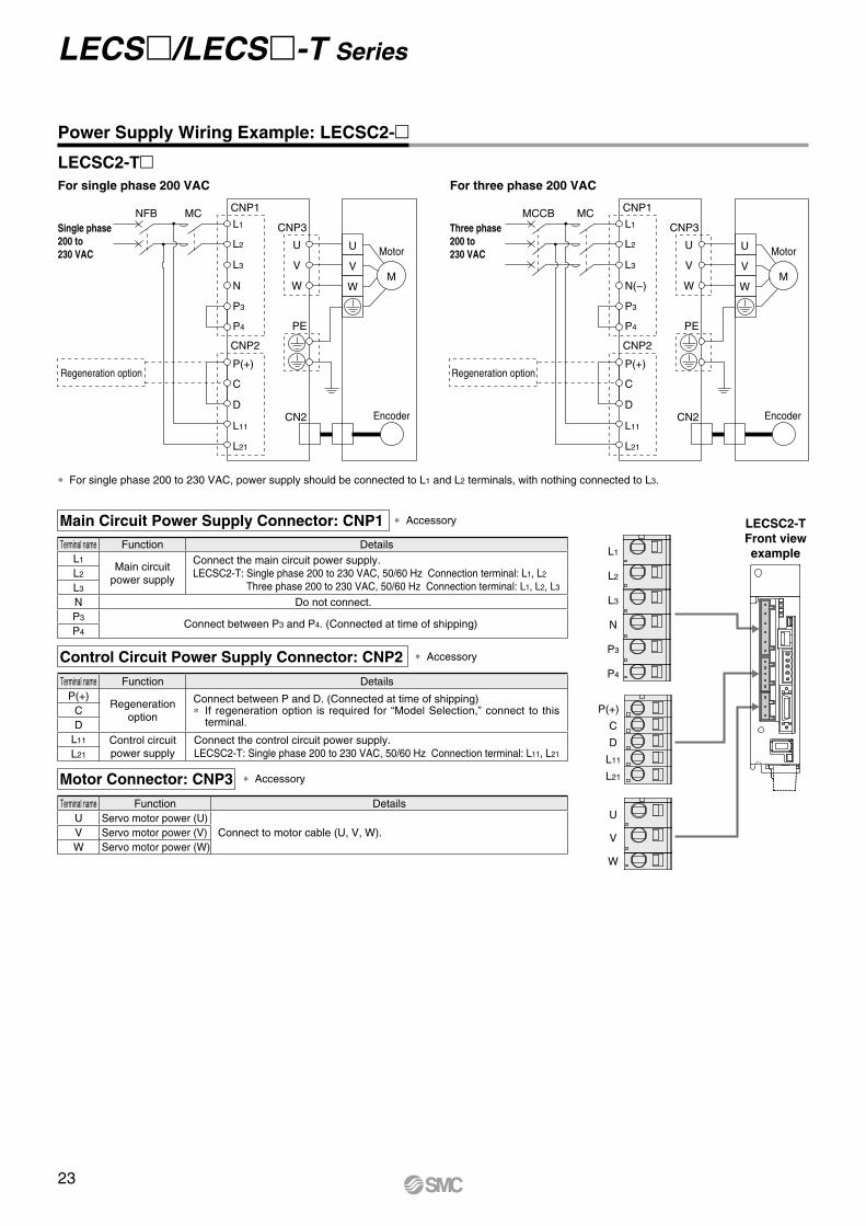
Power Supply Wiring Example: LECSA
LECSA-
* Accessory
* Accessory
Main Circuit Power Supply Connector: CNP1
Control Circuit Power Supply Connector: CNP2
Terminal name Function Details
24V Control circuit power supply (24 V)
24 V side of the control circuit power supply (24 VDC) supplied to the driver
0V Control circuit power supply (0 V)
0 V side of the control circuit power supply (24 VDC) supplied to the driver
Terminal name Function Details
Protective earth (PE) Should be grounded by connecting the servo motor’s earthterminal and the control panel’s protective earth (PE)
L1 Main circuitpower supply
Connect the main circuit power supply.LECSA1: Single phase 100 to 120 VAC, 50/60 HzLECSA2: Single phase 200 to 230 VAC, 50/60 HzL2
P
Regeneration option
Terminal to connect regeneration optionLECSA-S1: Not connected at time of shippingLECSA-S3, S4: Connected at time of shipping* If regeneration option is required for “Model Selection,”
connect to this terminal.C
U Servo motor power (U)Connect to motor cable (U, V, W).V Servo motor power (V)
W Servo motor power (W)
20
AC Servo Motor Driver LECS/LECS-T Series
LE
CS
/L
EC
S
-T S
erie
sL
EC
Y
Ser
ies
Sp
ecifi
c P
rodu
ctP
reca
utio
ns
L1
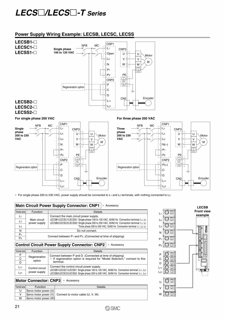
CNP1NFB MCCNP3
PE
CN2
Open
P1
P2
L2
U
V
W
U MotorV
WM
N
P
CNP2
C
L21
D
L11Encoder
Regeneration option
L1
CNP1NFB MCCNP3
PE
CN2
L2
P1
P2
L3
U
V
W
U MotorV
WM
N
P
CNP2
C
L21
D
L11Encoder
Regeneration option
L1
CNP1NFB MCCNP3
PE
CN2
L2
P1
P2
L3
U
V
W
U MotorV
WM
N(–)
P(+)
CNP2
C
L21
D
L11Encoder
Regeneration option
L1
L2
L3
N
P1
P2
P
C
D
L11
L21
U
V
W
Three phase200 to 230 VAC
Single phase200 to 230 VAC
Power Supply Wiring Example: LECSB, LECSC, LECSS
Single phase100 to 120 VAC
LECSB1-LECSC1-LECSS1-
LECSB2-LECSC2-LECSS2-
For three phase 200 VACFor single phase 200 VAC
Main Circuit Power Supply Connector: CNP1 * Accessory
* Accessory
* Accessory
* For single phase 200 to 230 VAC, power supply should be connected to L1 and L2 terminals, with nothing connected to L3.
Control Circuit Power Supply Connector: CNP2
Motor Connector: CNP3
Terminal name Function DetailsP
Regeneration option
Connect between P and D. (Connected at time of shipping)* If regeneration option is required for “Model Selection,” connect to this
terminal.CD
L11 Control circuit power supply
Connect the control circuit power supply.LECSB1/LECSC1/LECSS1: Single phase 100 to 120 VAC, 50/60 Hz Connection terminal: L11, L21
LECSB2/LECSC2/LECSS2: Single phase 200 to 230 VAC, 50/60 Hz Connection terminal: L11, L21L21
Terminal name Function DetailsU Servo motor power (U)
Connect to motor cable (U, V, W).V Servo motor power (V)W Servo motor power (W)
Terminal name Function Details
L1
Main circuitpower supply
Connect the main circuit power supply.LECSB1/LECSC1/LECSS1: Single phase 100 to 120 VAC, 50/60 Hz Connection terminal: L1, L2
LECSB2/LECSC2/LECSS2: Single phase 200 to 230 VAC, 50/60 Hz Connection terminal: L1, L2
Three phase 200 to 230 VAC, 50/60 Hz Connection terminal: L1, L2, L3
L2
L3
N Do not connect.P1
Connect between P1 and P2. (Connected at time of shipping)P2
LECSBFront view example
21
LECS/LECS-T Series
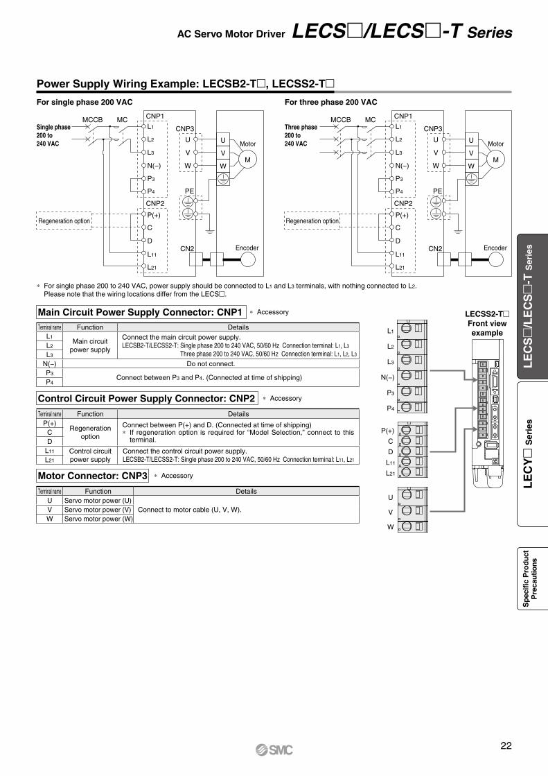
Terminal name Function DetailsL1
Main circuitpower supply
Connect the main circuit power supply.LECSB2-T/LECSS2-T: Single phase 200 to 240 VAC, 50/60 Hz Connection terminal: L1, L3
Three phase 200 to 240 VAC, 50/60 Hz Connection terminal: L1, L2, L3
L2
L3
N(−) Do not connect.P3
Connect between P3 and P4. (Connected at time of shipping)P4
L1
L2
L3
N(−)
P3
P4
P(+)
C
D
L11
L21
U
V
W
L1
CNP1MCCB MCCNP3
PE
CN2
L2
P3
P4
L3
U
V
W
U MotorV
WM
N(−)
P(+)
CNP2
C
L21
D
L11Encoder
Regeneration option
L1
CNP1MCCB MCCNP3
PE
CN2
L2
P3
P4
L3
U
V
W
U MotorV
WM
N(−)
P(+)
CNP2
C
L21
D
L11Encoder
Regeneration option
LECSS2-TFront view example
Power Supply Wiring Example: LECSB2-T, LECSS2-TFor three phase 200 VAC
Three phase200 to 240 VAC
For single phase 200 VAC
* For single phase 200 to 240 VAC, power supply should be connected to L1 and L3 terminals, with nothing connected to L2. Please note that the wiring locations differ from the LECS.
Single phase200 to 240 VAC
Main Circuit Power Supply Connector: CNP1 * Accessory
* Accessory
* Accessory
Control Circuit Power Supply Connector: CNP2
Motor Connector: CNP3
Terminal name Function DetailsP(+)
Regeneration option
Connect between P(+) and D. (Connected at time of shipping)* If regeneration option is required for “Model Selection,” connect to this
terminal.CD
L11 Control circuit power supply
Connect the control circuit power supply.LECSB2-T/LECSS2-T: Single phase 200 to 240 VAC, 50/60 Hz Connection terminal: L11, L21L21
Terminal name Function DetailsU Servo motor power (U)
Connect to motor cable (U, V, W).V Servo motor power (V)W Servo motor power (W)
22
AC Servo Motor Driver LECS/LECS-T Series
LE
CS
/L
EC
S
-T S
erie
sL
EC
Y
Ser
ies
Sp
ecifi
c P
rodu
ctP
reca
utio
ns
L1
CNP1NFB MCCNP3
PE
CN2
L2
P3
P4
L3
U
V
W
U MotorV
WM
N
P(+)
CNP2
C
L21
D
L11Encoder
Regeneration option
L1
L2
L3
N
P3
P4
P(+)
C
D
L11
L21
U
V
W
Terminal name Function DetailsL1
Main circuitpower supply
Connect the main circuit power supply.LECSC2-T: Single phase 200 to 230 VAC, 50/60 Hz Connection terminal: L1, L2
Three phase 200 to 230 VAC, 50/60 Hz Connection terminal: L1, L2, L3
L2
L3
N Do not connect.P3
Connect between P3 and P4. (Connected at time of shipping)P4
L1
CNP1MCCB MCCNP3
PE
CN2
L2
P3
P4
L3
U
V
W
U MotorV
WM
N(−)
P(+)
CNP2
C
L21
D
L11Encoder
Regeneration option
LECSC2-TFront view example
Power Supply Wiring Example: LECSC2-
For three phase 200 VAC
Three phase200 to 230 VAC
For single phase 200 VAC
* For single phase 200 to 230 VAC, power supply should be connected to L1 and L2 terminals, with nothing connected to L3.
Single phase200 to 230 VAC
Main Circuit Power Supply Connector: CNP1 * Accessory
* Accessory
* Accessory
Control Circuit Power Supply Connector: CNP2
Motor Connector: CNP3
Terminal name Function DetailsP(+)
Regeneration option
Connect between P and D. (Connected at time of shipping)* If regeneration option is required for “Model Selection,” connect to this
terminal.CD
L11 Control circuit power supply
Connect the control circuit power supply.LECSC2-T: Single phase 200 to 230 VAC, 50/60 Hz Connection terminal: L11, L21L21
Terminal name Function DetailsU Servo motor power (U)
Connect to motor cable (U, V, W).V Servo motor power (V)W Servo motor power (W)
LECSC2-T
23
LECS/LECS-T Series
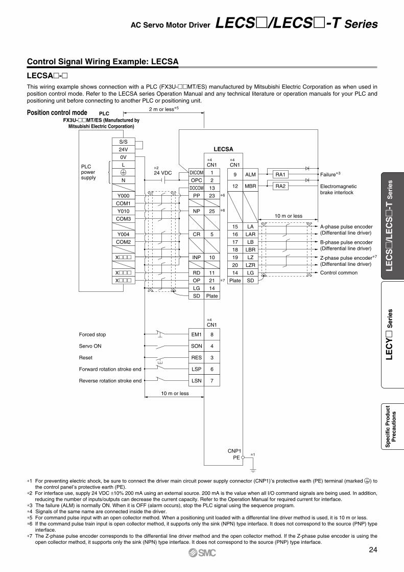
FX3U-MT/ES (Manufactured byMitsubishi Electric Corporation)
PLC
CNP1
PLC power supply
PE
S/S
24V
0V
L
N
S/SY000
COM1
Y010
COM3
COM2
X
XX
Y004
LECSA
24 VDC
CN1
DICOM
OPC
DOCOM
PP
NP
CR
RD
LG
SD
INP
OP
CN1
CN1
10 m or less
2 m or less∗5
10 m or less
1
2
13
23
25
5
11
14
Plate
10
21
9
12
15
Plate
20
ALM
EM1Forced stop
Servo ON
Reset
Forward rotation stroke end
Reverse rotation stroke end
8
SON 4
RES 3
LSP 6
LSN 7
MBR
LA
16 LAR
17 LB
18 LBR
19 LZ
SD
LZR
14 LG
Failure∗3
Electromagneticbrake interlock
A-phase pulse encoder(Differential line driver)
B-phase pulse encoder(Differential line driver)
Z-phase pulse encoder∗7
(Differential line driver)
Control common
RA1
RA2
∗7
∗6
∗6
∗2
∗1
∗4
∗4
∗4
Position control mode
Control Signal Wiring Example: LECSA
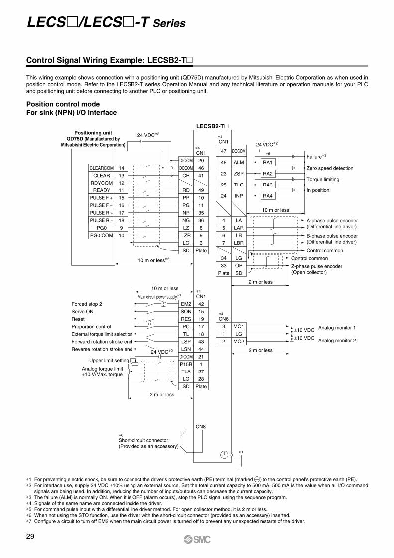
*1 For preventing electric shock, be sure to connect the driver main circuit power supply connector (CNP1),s protective earth (PE) terminal (marked ) to
the control panel,s protective earth (PE).
*2 For interface use, supply 24 VDC ±10% 200 mA using an external source. 200 mA is the value when all I/O command signals are being used. In addition, reducing the number of inputs/outputs can decrease the current capacity. Refer to the Operation Manual for required current for interface.
*3 The failure (ALM) is normally ON. When it is OFF (alarm occurs), stop the PLC signal using the sequence program.*4 Signals of the same name are connected inside the driver.*5 For command pulse input with an open collector method. When a positioning unit loaded with a differential line driver method is used, it is 10 m or less.*6 If the command pulse train input is open collector method, it supports only the sink (NPN) type interface. It does not correspond to the source (PNP) type
interface.*7 The Z-phase pulse encoder corresponds to the differential line driver method and the open collector method. If the Z-phase pulse encoder is using the
open collector method, it supports only the sink (NPN) type interface. It does not correspond to the source (PNP) type interface.
This wiring example shows connection with a PLC (FX3U-MT/ES) manufactured by Mitsubishi Electric Corporation as when used in position control mode. Refer to the LECSA series Operation Manual and any technical literature or operation manuals for your PLC and positioning unit before connecting to another PLC or positioning unit.
LECSA-
24
AC Servo Motor Driver LECS/LECS-T Series
LE
CS
/L
EC
S
-T S
erie
sL
EC
Y
Ser
ies
Sp
ecifi
c P
rodu
ctP
reca
utio
ns
CNP1
LECSA
24 VDC
CN1
OPC
DICOM
DOCOM
EM1
∗4, ∗5
∗2, ∗5CN1
10 m or less
10 m or less
∗1
2
1
13
8
SON 4
MD0 3
DOG 25
DI0 5
DI1 23
ST1 6
ST2 7
9
10
19
14
18
ALM
Forced stop
Servo ON
Automatic/Manual selection
Proximity dog
Point table no./Program no. selection 1
Point table no./Program no. selection 2Forward rotation start
Reverse rotation start
MEND
11 RD
12 MBR
LZ
20 LZR
15 LA
16 LAR
17 LB
LG
LBR
Plate SD
21 OP
Failure∗3
Travel completion
Ready
Z-phase pulse encoder∗6
(Differential line driver)
A-phase pulse encoder(Differential line driver)
B-phase pulse encoder(Differential line driver)
Control common
Control common
Z-phase pulse encoder∗6
(Open collector)
RA1
RA2
RA3
Electromagneticbrake interlock
RA4
2 m or less
*1 For preventing electric shock, be sure to connect the driver’s protective earth (PE) terminal (marked ) to the control panel’s protective earth (PE).*2 For interface use, supply 24 VDC ±10% 200 mA using an external source. 200 mA is the value when all I/O command signals are being used. In addition,
reducing the number of inputs/outputs can decrease the current capacity.*3 The failure (ALM) is normally ON.*4 Signals of the same name are connected inside the driver.*5 The wiring example is for the sink (NPN) type interface. Refer to the LECSA series Operation Manual for the source (PNP) type interface. Note that the
23 pin and 25 pin cannot be used for the source type interface.*6 The Z-phase pulse encoder corresponds to the differential line driver method and the open collector method. If the Z-phase pulse encoder is using the
open collector method, it supports only the sink (NPN) type interface. It does not correspond to the source (PNP) type interface.
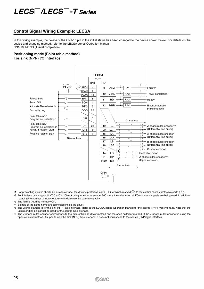
Control Signal Wiring Example: LECSA
In this wiring example, the device of the CN1-10 pin in the initial status has been changed to the device shown below. For details on the device and changing method, refer to the LECSA series Operation Manual.CN1-10: MEND (Travel completion)
Positioning mode (Point table method)For sink (NPN) I/O interface
LECS/LECS-T Series
25
Positioning unitQD75D (Manufactured by
Mitsubishi Electric Corporation)
PE
CLEARCOM
CLEAR
RDYCOM
READY
PULSE F+
PULSE F–
S/S
PG0
PG0 COM
LECSB
24 VDC∗2
CN1
DICOM
DOCOM
CR
PP
NG
LG
LZ
SD
CN1
CN1
CN6
2 m or less
10 m or less
10 m or less∗5
2 m or less
10 m or less
20
46
41
10
PG 11
NP 35
36
3
LZR 9
8
Plate
21
48
Plate
33
DICOM
EMGEmergency stop
Servo ON
Reset
Proportion control
External torque limit selection
Forward rotation stroke end
Reverse rotation stroke end
Analog torque limit+10 V/Max. torque
Upper limit setting
42
SON 15
RES 19
PC 17
TL 18
LSP 43
LSN 44
DOCOM 47
P15R 1
TLA 27
LG 28
SD Plate
ALM
23 ZSP
25 TLC
24 INP
4 LA
5 LAR
6 LB
7 LBR
SD
OP
34 LG
1 P15R
Failure∗3
Zero speed detection
Torque limiting
Positioning completion
A-phase pulse encoder(Differential line driver)
B-phase pulse encoder(Differential line driver)
Z-phase pulse encoder∗7
(Open collector)
Control common
Control common
RA1
RA2
RA3
2 m or less
1 LG
3 MO1
2 MO2 Analog monitor 2
Analog monitor 1
±10 VDC
±10 VDC
RA4
PULSE R+
PULSE R–
14
13
12
11
15
16
10
9
17
18
RD 49
∗1
∗4
∗4
∗7
∗4
∗4
∗6
∗6
Control Signal Wiring Example: LECSB
*1 For preventing electric shock, be sure to connect the driver,s protective earth (PE) terminal (marked ) to the control panel
,s protective earth (PE).
*2 For interface use, supply 24 VDC ±10% 300 mA using an external source.*3 The failure (ALM) is normally ON. When it is OFF (alarm occurs), stop the PLC signal using the sequence program.*4 Signals of the same name are connected inside the driver.*5 For command pulse input with a differential line driver method. For open collector method, it is 2 m or less.*6 If the command pulse train input is open collector method, it supports only the sink (NPN) type interface. It does not correspond to the source (PNP) type
interface.*7 The Z-phase pulse encoder corresponds to the differential line driver method and the open collector method. If the Z-phase pulse encoder is using the
open collector method, it supports only the sink (NPN) type interface. It does not correspond to the source (PNP) type interface.
This wiring example shows connection with a positioning unit (QD75D) manufactured by Mitsubishi Electric Corporation as when used in position control mode. Refer to the LECSB series Operation Manual and any technical literature or operation manuals for your PLC and positioning unit before connecting to another PLC or positioning unit.
26
AC Servo Motor Driver LECS/LECS-T Series
LE
CS
/L
EC
S
-T S
erie
sL
EC
Y
Ser
ies
Sp
ecifi
c P
rodu
ctP
reca
utio
ns
PE
CN6
LECSC/LECSC2-T
CN6
10 m or less
10 m or less
14
15
Plate
25
RD
DICOM
Forced stop
Proximity dog
Forward rotation stroke end
Reverse rotation stroke end
5
DOCOM 17
EMG 1
DOG 2
LSP 3
LSN 4
ALM
16 ZP
13 LZ
26 LZR
11 LA
24 LAR
SD
LBR
12 LB
23 LG
Ready
Failure∗3
Return to origin completion
Z-phase pulse encoder(Differential line driver)
A-phase pulse encoder(Differential line driver)
B-phase pulse encoder(Differential line driver)
Control common
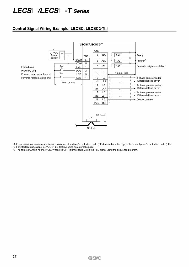
RA1
RA2
RA3
+24 VDC
−Powersupply
CN1
CC-Link
∗1
∗2
Control Signal Wiring Example: LECSC, LECSC2-T
*1 For preventing electric shock, be sure to connect the driver,s protective earth (PE) terminal (marked ) to the control panel
,s protective earth (PE).
*2 For interface use, supply 24 VDC ±10% 150 mA using an external source.*3 The failure (ALM) is normally ON. When it is OFF (alarm occurs), stop the PLC signal using the sequence program.
27
LECS/LECS-T Series
PE
LECSS
LECSS
CN3CN3
10 m or less 10 m or less
13
9
4
11
MBRDICOM
Forced stop
Upper stroke limit (FLS)
Lower stroke limit (RLS)
Proximity dog (DOG)
5
DOCOM 3
EM1 20
D11 2
D12 12
D13 19
INP
15 ALM
10 DICOM
6 LA
16 LAR
7 LB
17 LBR
8 LZ
MO1
1 LG
14 MO2
Plate SD
LG
18 LZR
Electromagnetic brake interlock∗2
In position
Failure∗3
A-phase pulse encoder(Differential line driver)
SSCNET#optical cable∗5
(Option)
SSCNET#optical cable∗5
(Option)
Cap∗8
Servo systemcontroller
B-phase pulse encoder(Differential line driver)
Z-phase pulse encoder(Differential line driver)
Control common
Analog monitor 1
Analog monitor 2
SW1
SW2
(Axis 2)
1 2
SW1
SW2
1 2
RA2
RA3
2 m or less
CN1A
CN1B
CN1A
CN1B
CN1A
CN1B
CN1A
CN1B
RA1
LECSS(Axis 3)
SW1
SW2
1 2
LECSS(Axis n)
SW1
SW2
1 2
24 VDC
∗7
∗2 ∗4 ∗4
∗1
∗6
∗7
∗6
∗7
∗6
∗7
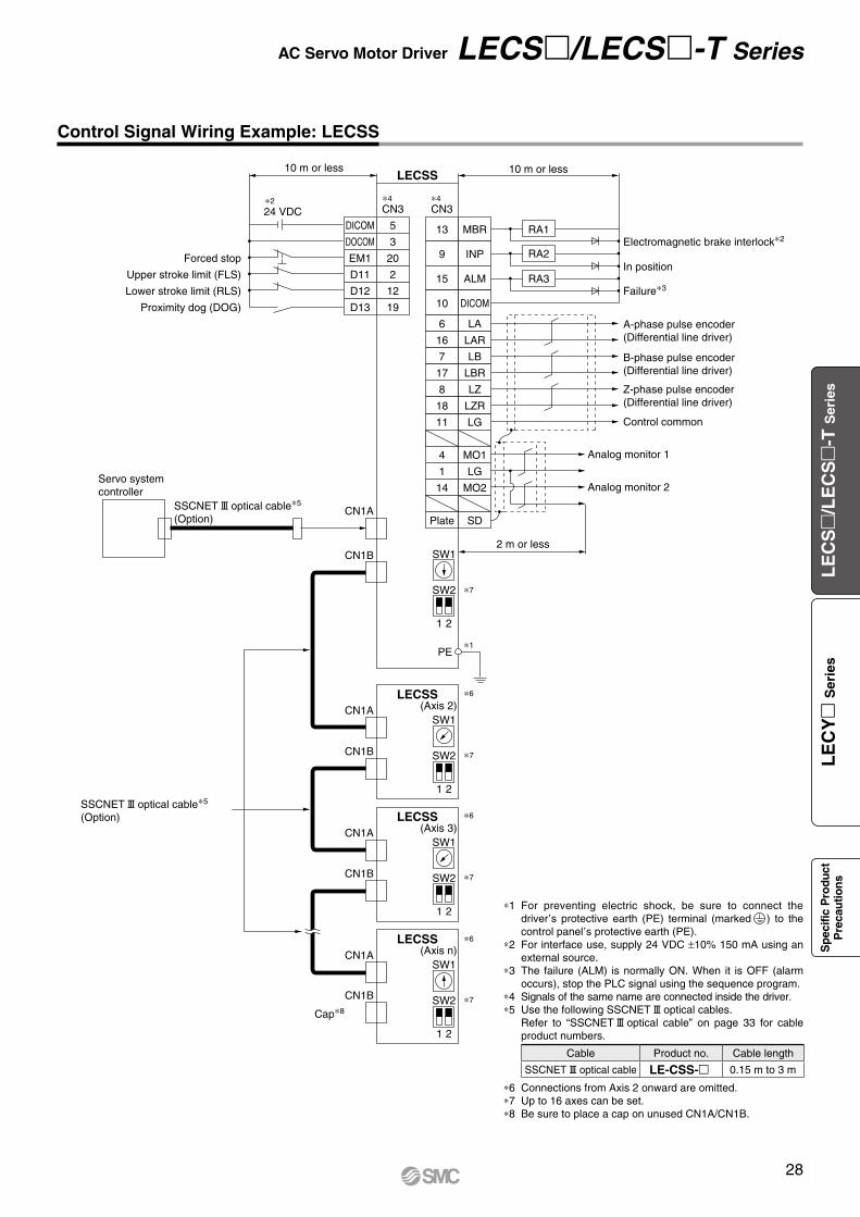
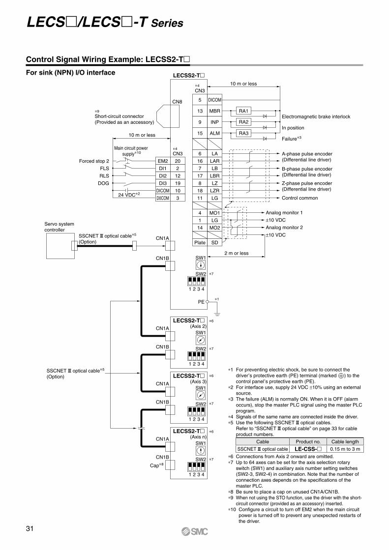
Control Signal Wiring Example: LECSS
*1 For preventing electric shock, be sure to connect the driver
,s protective earth (PE) terminal (marked ) to the
control panel,s protective earth (PE).
*2 For interface use, supply 24 VDC ±10% 150 mA using an external source.
*3 The failure (ALM) is normally ON. When it is OFF (alarm occurs), stop the PLC signal using the sequence program.
*4 Signals of the same name are connected inside the driver.*5 Use the following SSCNET#optical cables.
Refer to “SSCNET#optical cable” on page 33 for cable product numbers.
*6 Connections from Axis 2 onward are omitted.*7 Up to 16 axes can be set.*8 Be sure to place a cap on unused CN1A/CN1B.
Cable Product no. Cable length
SSCNET#optical cable LE-CSS- 0.15 m to 3 m
28
AC Servo Motor Driver LECS/LECS-T Series
LE
CS
/L
EC
S
-T S
erie
sL
EC
Y
Ser
ies
Sp
ecifi
c P
rodu
ctP
reca
utio
ns
Positioning unitQD75D (Manufactured by
Mitsubishi Electric Corporation)
CLEARCOM
CLEAR
RDYCOM
READY
PULSE F +
PULSE F −
PG0
PG0 COM
LECSB2-T24 VDC∗2
CN1
DICOM
DOCOM
CR
PP
NG
LG
LZ
SD
CN1
CN1
CN6
2 m or less
10 m or less
10 m or less∗5
2 m or less
10 m or less
20
46
41
10
PG 11
NP 35
36
3
LZR 9
8
Plate
47
48
Plate
33
DOCOM
EM2Forced stop 2
Servo ON
Reset
Proportion control
External torque limit selection
Forward rotation stroke end
Reverse rotation stroke end
Analog torque limit+10 V/Max. torque
Upper limit setting
42
SON 15
RES 19
PC 17
TL 18
LSP 43
LSN 44
DICOM 21
P15R 1
TLA 27
LG 28
SD Plate
ALM
23 ZSP
25 TLC
24 INP
4 LA
5 LAR
6 LB
7 LBR
SD
OP
34 LG
Failure∗3
Zero speed detection
Torque limiting
In position
A-phase pulse encoder(Differential line driver)
B-phase pulse encoder(Differential line driver)
Z-phase pulse encoder(Open collector)
Control common
Control common
RA1
RA2
RA3
2 m or less
1 LG
3 MO1
2 MO2 Analog monitor 2
Analog monitor 1
±10 VDC
±10 VDC
RA4
PULSE R +
PULSE R −
14
13
12
11
15
16
10
9
17
18
RD 49
24 VDC∗2
24 VDC∗2
Main circuit power supply∗7
CN8
Short-circuit connector(Provided as an accessory)
∗4
∗4
∗4
∗6
∗1
∗4
∗6
*1 For preventing electric shock, be sure to connect the driver’s protective earth (PE) terminal (marked ) to the control panel’s protective earth (PE).*2 For interface use, supply 24 VDC ±10% using an external source. Set the total current capacity to 500 mA. 500 mA is the value when all I/O command
signals are being used. In addition, reducing the number of inputs/outputs can decrease the current capacity.*3 The failure (ALM) is normally ON. When it is OFF (alarm occurs), stop the PLC signal using the sequence program.*4 Signals of the same name are connected inside the driver.*5 For command pulse input with a differential line driver method. For open collector method, it is 2 m or less.*6 When not using the STO function, use the driver with the short-circuit connector (provided as an accessory) inserted.*7 Configure a circuit to turn off EM2 when the main circuit power is turned off to prevent any unexpected restarts of the driver.
This wiring example shows connection with a positioning unit (QD75D) manufactured by Mitsubishi Electric Corporation as when used in position control mode. Refer to the LECSB2-T series Operation Manual and any technical literature or operation manuals for your PLC and positioning unit before connecting to another PLC or positioning unit.
Control Signal Wiring Example: LECSB2-T
Position control modeFor sink (NPN) I/O interface
29
LECS/LECS-T Series
LECSB2-T
CN1∗4
CN1
CN6∗4
2 m or less
10 m or less
2 m or less
10 m or less
∗4
∗1
46
47
7
DOCOM
DI0
Forced stop 2
Servo ON
Operation mode selection 1
Forward rotation start
Reverse rotation start
Proximity dog
Forward rotation stroke end
Reverse rotation stroke end
Point table no. selection 1
Point table no. selection 2
Point table no. selection 3
Point table no. selection 4
Analog torque limit+10 V/Max. torque
Upper limit setting
19
LSN 44
LSP 43
DOG 45
ST2 18
ST1 17
MD0 16
SON 15
EM2 42
DI1 41
DI2 10
DI3 35
DICOM 20
DICOM 21
OPC 12
P15R 1
VC 2
LG 28
TLA 27
SD Plate
DOCOM
48 ALM
22 CPO
23 ZP
25 MEND
24 INP
49 RD
14
13 ∗7
∗7
8 LZ
9 LZR
4 LA
5 LAR
34 LG
33 OP
Plate SD
LBR
6 LB
Failure∗3
Rough match
Return to origin completion
Z-phase pulse encoder(Differential line driver)
A-phase pulse encoder(Differential line driver)
B-phase pulse encoder(Differential line driver)
Z-phase pulse encoder(Open collector)
Control common
Control common
RA1
RA2
2 m or less
1 LG
3 MO1
2 MO2 Analog monitor 2
Analog monitor 1
±10 VDC
±10 VDC
RA3
Travel completionRA4
In positionRA5
ReadyRA6
24 VDC∗2
Analog override±10 V/0 to 200%
Upper limit setting
24 VDC∗2
Main circuit power supply∗6
CN8
Short-circuit connector(Provided as an accessory)
∗5
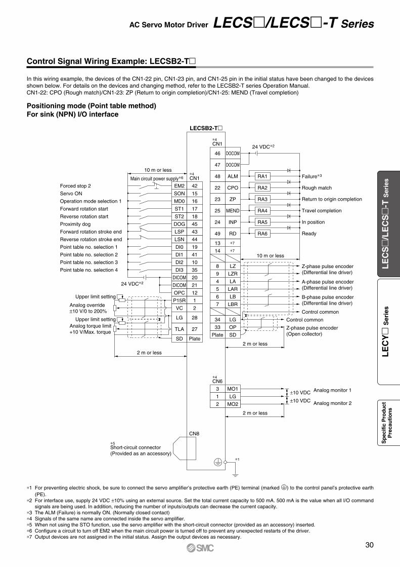
*1 For preventing electric shock, be sure to connect the servo amplifier’s protective earth (PE) terminal (marked ) to the control panel’s protective earth (PE).
*2 For interface use, supply 24 VDC ±10% using an external source. Set the total current capacity to 500 mA. 500 mA is the value when all I/O command signals are being used. In addition, reducing the number of inputs/outputs can decrease the current capacity.
*3 The ALM (Failure) is normally ON. (Normally closed contact)*4 Signals of the same name are connected inside the servo amplifier.*5 When not using the STO function, use the servo amplifier with the short-circuit connector (provided as an accessory) inserted.*6 Configure a circuit to turn off EM2 when the main circuit power is turned off to prevent any unexpected restarts of the driver.*7 Output devices are not assigned in the initial status. Assign the output devices as necessary.
In this wiring example, the devices of the CN1-22 pin, CN1-23 pin, and CN1-25 pin in the initial status have been changed to the devices shown below. For details on the devices and changing method, refer to the LECSB2-T series Operation Manual.CN1-22: CPO (Rough match)/CN1-23: ZP (Return to origin completion)/CN1-25: MEND (Travel completion)
Control Signal Wiring Example: LECSB2-T
Positioning mode (Point table method)For sink (NPN) I/O interface
AC Servo Motor Driver LECS/LECS-T Series
30
LE
CS
/L
EC
S
-T S
erie
sL
EC
Y
Ser
ies
Sp
ecifi
c P
rodu
ctP
reca
utio
ns
PE
LECSS2-T
LECSS2-T
CN3
CN8
∗9
CN3
10 m or less
10 m or less
13
9
4
11
MBR
DICOM
Forced stop 2
Short-circuit connector(Provided as an accessory)
FLS
RLS
DOG
10
D0COM 3
EM2 20
DI1 2
DI2 12
DI3 19
INP
15 ALM
6 LA
16 LAR
7 LB
17 LBR
8 LZ
MO1
1 LG
14 MO2
Plate SD
LG
18 LZR
Electromagnetic brake interlock
In position
Failure∗3
A-phase pulse encoder (Differential line driver)
SSCNET#optical cable∗5
(Option)
SSCNET#optical cable∗5
(Option)
Cap∗8
Servo systemcontroller
B-phase pulse encoder (Differential line driver)
Z-phase pulse encoder (Differential line driver)
Control common
Analog monitor 1
±10 VDC
±10 VDC
Analog monitor 2
SW1
SW2
(Axis 2)
31 2 4
31 2 4
31 2 4
31 2 4
SW1
SW2
RA2
RA3
2 m or less
CN1A
CN1B
CN1A
CN1B
CN1A
CN1B
CN1A
CN1B
RA1
LECSS2-T(Axis 3)
SW1
SW2
LECSS2-T(Axis n)
SW1
SW2
Main circuit power supply∗10
24 VDC∗2
5 DICOM
∗7
∗4
∗4
∗1
∗6
∗7
∗6
∗7
∗6
∗7
Control Signal Wiring Example: LECSS2-T
*1 For preventing electric shock, be sure to connect the driver
,s protective earth (PE) terminal (marked ) to the
control panel,s protective earth (PE).
*2 For interface use, supply 24 VDC ±10% using an external source.
*3 The failure (ALM) is normally ON. When it is OFF (alarm occurs), stop the master PLC signal using the master PLC program.
*4 Signals of the same name are connected inside the driver.*5 Use the following SSCNET#optical cables.
Refer to “SSCNET#optical cable” on page 33 for cable product numbers.
Cable Product no. Cable length
SSCNET#optical cable LE-CSS- 0.15 m to 3 m
*6 Connections from Axis 2 onward are omitted.*7 Up to 64 axes can be set for the axis selection rotary
switch (SW1) and auxiliary axis number setting switches (SW2-3, SW2-4) in combination. Note that the number of connection axes depends on the specifications of the master PLC.
*8 Be sure to place a cap on unused CN1A/CN1B.*9 When not using the STO function, use the driver with the short-
circuit connector (provided as an accessory) inserted.*10 Configure a circuit to turn off EM2 when the main circuit
power is turned off to prevent any unexpected restarts of the driver.
For sink (NPN) I/O interface
31
LECS/LECS-T Series
(30) L
(13.
7)
øD
L(29.6)
(11.
8)
øD
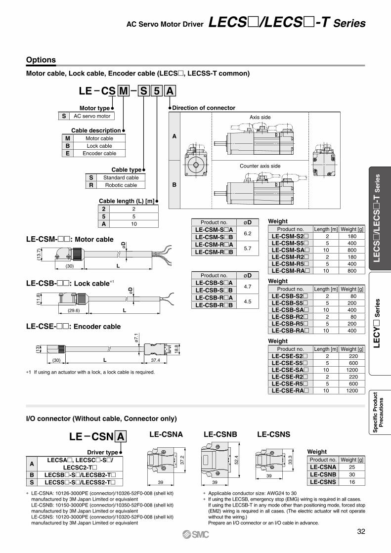
Options
Motor cable, Lock cable, Encoder cable (LECS, LECSS-T common)
Cable type
Cable description
Motor type
Cable length (L) [m]
LE CS M S 5 A
I/O connector (Without cable, Connector only)
39
37.2
LE-CSNA
Driver type
52.4
39
LE-CSNB
33.3
39
LE-CSNSLE CSN A
LE-CSM-: Motor cable
LE-CSB-: Lock cable*1
LE-CSE-: Encoder cable
Direction of connector
A
Axis side
B
Counter axis side
ALECSA, LECSC-S/
LECSC2-TB LECSB-S/LECSB2-TS LECSS-S/LECSS2-T
2 2
5 5
A 10
S Standard cable
R Robotic cable
S AC servo motor
M Motor cable
B Lock cable
E Encoder cable
Product no. øDLE-CSM-SA
6.2LE-CSM-SBLE-CSM-RA
5.7LE-CSM-RB
Product no. øDLE-CSB-SA
4.7LE-CSB-SBLE-CSB-RA
4.5LE-CSB-RB
*1 If using an actuator with a lock, a lock cable is required.
* LE-CSNA: 10126-3000PE (connector)/10326-52F0-008 (shell kit) manufactured by 3M Japan Limited or equivalent LE-CSNB: 10150-3000PE (connector)/10350-52F0-008 (shell kit) manufactured by 3M Japan Limited or equivalent LE-CSNS: 10120-3000PE (connector)/10320-52F0-008 (shell kit) manufactured by 3M Japan Limited or equivalent
* Applicable conductor size: AWG24 to 30* If using the LECSB, emergency stop (EMG) wiring is required in all cases.
If using the LECSB-T in any mode other than positioning mode, forced stop (EM2) wiring is required in all cases. (The electric actuator will not operate without the wiring.)Prepare an I/O connector or an I/O cable in advance.
WeightProduct no. Length [m] Weight [g]
LE-CSM-S2 2 180LE-CSM-S5 5 400LE-CSM-SA 10 800LE-CSM-R2 2 180LE-CSM-R5 5 400LE-CSM-RA 10 800
WeightProduct no. Length [m] Weight [g]
LE-CSE-S2 2 220LE-CSE-S5 5 600LE-CSE-SA 10 1200LE-CSE-R2 2 220LE-CSE-R5 5 600LE-CSE-RA 10 1200
WeightProduct no. Length [m] Weight [g]
LE-CSB-S2 2 80LE-CSB-S5 5 200LE-CSB-SA 10 400LE-CSB-R2 2 80LE-CSB-R5 5 200LE-CSB-RA 10 400
WeightProduct no. Weight [g]
LE-CSNA 25
LE-CSNB 30
LE-CSNS 16
AC Servo Motor Driver LECS/LECS-T Series(1
3)
(30) L 37.4
18.8
ø7.
1
32
LE
CS
/L
EC
S
-T S
erie
sL
EC
Y
Ser
ies
Sp
ecifi
c P
rodu
ctP
reca
utio
ns
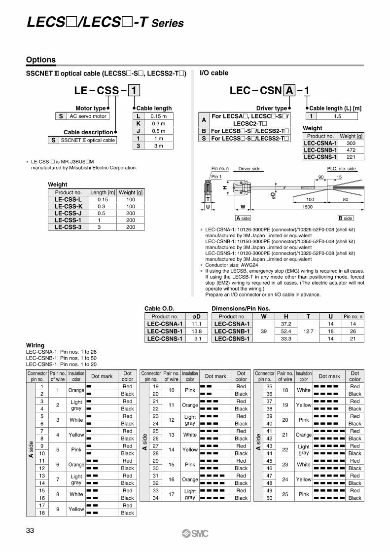
1
Name plate + Lot. No.
A side B side
UT
W
H
Pin 1
Pin no. n
1500
80100
PLC, etc. sideDriver side
90 15
øD
∗ LEC-CSNA-1: 10126-3000PE (connector)/10326-52F0-008 (shell kit) manufactured by 3M Japan Limited or equivalentLEC-CSNB-1: 10150-3000PE (connector)/10350-52F0-008 (shell kit) manufactured by 3M Japan Limited or equivalentLEC-CSNS-1: 10120-3000PE (connector)/10320-52F0-008 (shell kit) manufactured by 3M Japan Limited or equivalent
∗ Conductor size: AWG24∗ If using the LECSB, emergency stop (EMG) wiring is required in all cases.
If using the LECSB-T in any mode other than positioning mode, forced stop (EM2) wiring is required in all cases. (The electric actuator will not operate without the wiring.)Prepare an I/O connector or an I/O cable in advance.
WiringLEC-CSNA-1: Pin nos. 1 to 26LEC-CSNB-1: Pin nos. 1 to 50LEC-CSNS-1: Pin nos. 1 to 20
I/O cable
Connectorpin no.
Pair no. of wire
Insulationcolor Dot mark Dot
color
A s
ide
11 Orange
Red2 Black3
2 Light gray
Red4 Black5
3 WhiteRed
6 Black7
4 YellowRed
8 Black9
5 PinkRed
10 Black11
6 OrangeRed
12 Black13
7 Light gray
Red14 Black15
8 WhiteRed
16 Black17
9 YellowRed
18 Black
Connectorpin no.
Pair no. of wire
Insulationcolor Dot mark Dot
color
A s
ide
1910 Pink
Red20 Black21
11 OrangeRed
22 Black23
12 Light gray
Red24 Black25
13 WhiteRed
26 Black27
14 YellowRed
28 Black29
15 PinkRed
30 Black31
16 OrangeRed
32 Black33
17 Light gray
Red34 Black
Connectorpin no.
Pair no. of wire
Insulationcolor Dot mark Dot
color
A s
ide
3518 White
Red36 Black37
19 YellowRed
38 Black39
20 PinkRed
40 Black41
21 OrangeRed
42 Black43
22 Light gray
Red44 Black45
23 WhiteRed
46 Black47
24 YellowRed
48 Black49
25 PinkRed
50 Black
∗ LE-CSS- is MR-J3BUSMmanufactured by Mitsubishi Electric Corporation.
SSCNET#optical cable (LECSS-S, LECSS2-T)
Cable O.D.Product no. øD
LEC-CSNA-1 11.1
LEC-CSNB-1 13.8
LEC-CSNS-1 9.1
Dimensions/Pin Nos.Product no. W H T U Pin no. n
LEC-CSNA-139
37.212.7
14 14
LEC-CSNB-1 52.4 18 26
LEC-CSNS-1 33.3 14 21
1
Cable lengthL 0.15 m
K 0.3 m
J 0.5 m
1 1 m
3 3 m
LE CSS
Motor typeS AC servo motor
Cable descriptionS SSCNET#optical cable
LEC CSN A
Driver type
AFor LECSA, LECSC-S/
LECSC2-TB For LECSB-S/LECSB2-TS For LECSS-S/LECSS2-T
Cable length (L) [m]1 1.5
Options
WeightProduct no. Length [m] Weight [g]LE-CSS-L 0.15 100LE-CSS-K 0.3 100LE-CSS-J 0.5 200LE-CSS-1 1 200LE-CSS-3 3 200
WeightProduct no. Weight [g]
LEC-CSNA-1 303LEC-CSNB-1 472LEC-CSNS-1 221
33
LECS/LECS-T Series
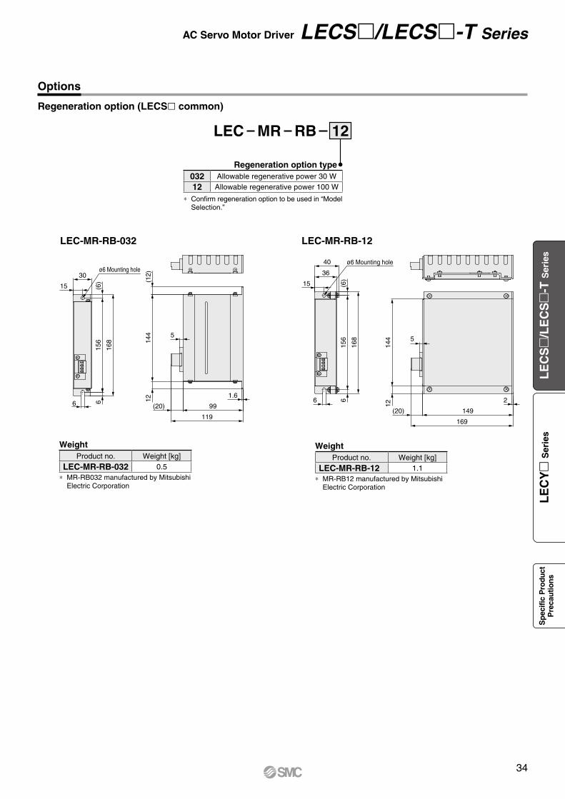
6
ø6 Mounting hole
(6)
156
168
6
30
15
1214
4(1
2)
5
1.6
(20)
119
99
(6)
ø6 Mounting hole40
36
15
168
156
66
149
5
144
12
(20)
169
2
12
Regeneration option type032 Allowable regenerative power 30 W
12 Allowable regenerative power 100 W
∗ Confirm regeneration option to be used in “Model Selection.”
Regeneration option (LECSl common)
LEC MR RB
WeightProduct no. Weight [kg]
LEC-MR-RB-032 0.5∗ MR-RB032 manufactured by Mitsubishi
Electric Corporation
WeightProduct no. Weight [kg]
LEC-MR-RB-12 1.1∗ MR-RB12 manufactured by Mitsubishi
Electric Corporation
LEC-MR-RB-032 LEC-MR-RB-12
Options
34
AC Servo Motor Driver LECS/LECS-T Series
LE
CS
/L
EC
S
-T S
erie
sL
EC
Y
Ser
ies
Sp
ecifi
c P
rodu
ctP
reca
utio
ns
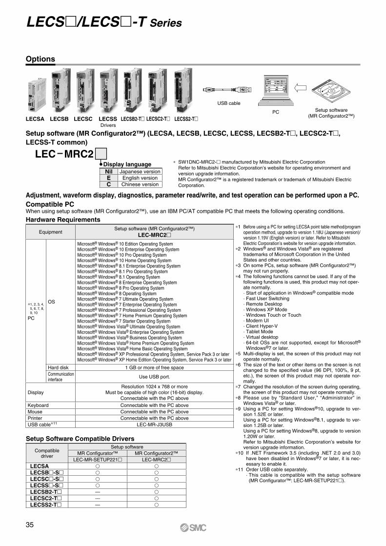
USB cable
PC Setup software(MR Configurator2™)
DriversLECSA LECSB LECSC LECSS LECSS2-TLECSB2-T LECSC2-T
Compatible PC
Hardware Requirements
Setup Software Compatible Drivers
When using setup software (MR Configurator2™), use an IBM PC/AT compatible PC that meets the following operating conditions.
Setup software (MR Configurator2™) (LECSA, LECSB, LECSC, LECSS, LECSB2-T, LECSC2-T, LECSS-T common)
LEC MRC2* SW1DNC-MRC2- manufactured by Mitsubishi Electric Corporation
Refer to Mitsubishi Electric Corporation’s website for operating environment and version upgrade information.MR Configurator2™ is a registered trademark or trademark of Mitsubishi Electric Corporation.
Display language
Adjustment, waveform display, diagnostics, parameter read/write, and test operation can be performed upon a PC.
*1 Before using a PC for setting LECSA point table method/program operation method, upgrade to version 1.18U (Japanese version)/version 1.19V (English version) or later. Refer to Mitsubishi Electric Corporation’s website for version upgrade information.
*2 Windows® and Windows Vista® are registered trademarks of Microsoft Corporation in the United States and other countries.
*3 On some PCs, setup software (MR Configurator2™) may not run properly.
*4 The following functions cannot be used. If any of the following functions is used, this product may not oper-ate normally.· Start of application in Windows® compatible mode· Fast User Switching· Remote Desktop· Windows XP Mode· Windows Touch or Touch· Modern UI· Client Hyper-V· Tablet Mode· Virtual desktop· 64-bit OSs are not supported, except for Microsoft® Windows®7 or later.
*5 Multi-display is set, the screen of this product may not operate normally.
*6 The size of the text or other items on the screen is not changed to the specified value (96 DPI, 100%, 9 pt, etc.), the screen of this product may not operate nor-mally.
*7 Changed the resolution of the screen during operating, the screen of this product may not operate normally.
*8 Please use by “Standard User,” “Administrator” in Windows Vista® or later.
*9 Using a PC for setting Windows®10, upgrade to ver-sion 1.52E or later. Using a PC for setting Windows®8.1, upgrade to ver-sion 1.25B or later. Using a PC for setting Windows®8, upgrade to version 1.20W or later. Refer to Mitsubishi Electric Corporation’s website for version upgrade information.
*10 If .NET Framework 3.5 (including .NET 2.0 and 3.0) have been disabled in Windows®7 or later, it is nec-essary to enable it.
*11 Order USB cable separately.· This cable is compatible with the setup software
(MR Configurator™: LEC-MR-SETUP221).
EquipmentSetup software (MR Configurator2™)
LEC-MRC2
*1, 2, 3, 4, 5, 6, 7, 8, 9, 10
PC
OS
Microsoft® Windows® 10 Edition Operating SystemMicrosoft® Windows® 10 Enterprise Operating SystemMicrosoft® Windows® 10 Pro Operating SystemMicrosoft® Windows® 10 Home Operating SystemMicrosoft® Windows® 8.1 Enterprise Operating SystemMicrosoft® Windows® 8.1 Pro Operating SystemMicrosoft® Windows® 8.1 Operating SystemMicrosoft® Windows® 8 Enterprise Operating SystemMicrosoft® Windows® 8 Pro Operating SystemMicrosoft® Windows® 8 Operating SystemMicrosoft® Windows® 7 Ultimate Operating SystemMicrosoft® Windows® 7 Enterprise Operating SystemMicrosoft® Windows® 7 Professional Operating SystemMicrosoft® Windows® 7 Home Premium Operating SystemMicrosoft® Windows® 7 Starter Operating SystemMicrosoft® Windows Vista® Ultimate Operating SystemMicrosoft® Windows Vista® Enterprise Operating SystemMicrosoft® Windows Vista® Business Operating SystemMicrosoft® Windows Vista® Home Premium Operating SystemMicrosoft® Windows Vista® Home Basic Operating SystemMicrosoft® Windows® XP Professional Operating System, Service Pack 3 or laterMicrosoft® Windows® XP Home Edition Operating System, Service Pack 3 or later
Hard disk 1 GB or more of free space Communication interface Use USB port.
DisplayResolution 1024 x 768 or more
Must be capable of high color (16-bit) display.Connectable with the PC above
Keyboard Connectable with the PC aboveMouse Connectable with the PC abovePrinter Connectable with the PC aboveUSB cable*11 LEC-MR-J3USB
Compatibledriver
Setup softwareMR Configurator™ MR Configurator2™
LEC-MR-SETUP221 LEC-MRC2LECSA v v
LECSB-S v v
LECSC-S v v
LECSS-S v v
LECSB2-T — v
LECSC2-T — v
LECSS2-T — v
Nil Japanese versionE English versionC Chinese version
Options
35
LECS/LECS-T Series
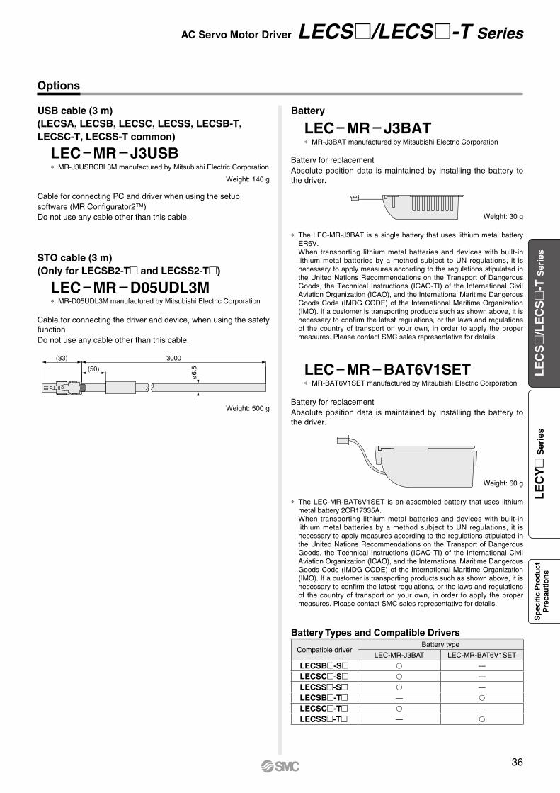
Battery
Battery Types and Compatible Drivers
Compatible driverBattery type
LEC-MR-J3BAT LEC-MR-BAT6V1SET
LECSB-S —
LECSC-S —
LECSS-S —
LECSB-T —
LECSC-T —
LECSS-T —
Options
* The LEC-MR-BAT6V1SET is an assembled battery that uses lithium metal battery 2CR17335A.When transporting lithium metal batteries and devices with built-in lithium metal batteries by a method subject to UN regulations, it is necessary to apply measures according to the regulations stipulated in the United Nations Recommendations on the Transport of Dangerous Goods, the Technical Instructions (ICAO-TI) of the International Civil Aviation Organization (ICAO), and the International Maritime Dangerous Goods Code (IMDG CODE) of the International Maritime Organization (IMO). If a customer is transporting products such as shown above, it is necessary to confirm the latest regulations, or the laws and regulations of the country of transport on your own, in order to apply the proper measures. Please contact SMC sales representative for details.
LEC MR BAT6V1SET* MR-BAT6V1SET manufactured by Mitsubishi Electric Corporation
Battery for replacementAbsolute position data is maintained by installing the battery to the driver.
STO cable (3 m)(Only for LECSB2-T and LECSS2-T)
LEC MR D05UDL3M* MR-D05UDL3M manufactured by Mitsubishi Electric Corporation
Cable for connecting the driver and device, when using the safety functionDo not use any cable other than this cable.
(33) 3000
(50)
ø6.
5
USB cable (3 m)(LECSA, LECSB, LECSC, LECSS, LECSB-T, LECSC-T, LECSS-T common)
LEC MR J3USB
LEC MR J3BAT
Cable for connecting PC and driver when using the setupsoftware (MR Configurator2™)Do not use any cable other than this cable.
* MR-J3BAT manufactured by Mitsubishi Electric Corporation
* MR-J3USBCBL3M manufactured by Mitsubishi Electric CorporationBattery for replacementAbsolute position data is maintained by installing the battery to the driver.
* The LEC-MR-J3BAT is a single battery that uses lithium metal battery ER6V.When transporting lithium metal batteries and devices with built-in lithium metal batteries by a method subject to UN regulations, it is necessary to apply measures according to the regulations stipulated in the United Nations Recommendations on the Transport of Dangerous Goods, the Technical Instructions (ICAO-TI) of the International Civil Aviation Organization (ICAO), and the International Maritime Dangerous Goods Code (IMDG CODE) of the International Maritime Organization (IMO). If a customer is transporting products such as shown above, it is necessary to confirm the latest regulations, or the laws and regulations of the country of transport on your own, in order to apply the proper measures. Please contact SMC sales representative for details.
Weight: 140 g
Weight: 30 g
Weight: 60 g
Weight: 500 g
36
AC Servo Motor Driver LECS/LECS-T Series
LE
CS
/L
EC
S
-T S
erie
sL
EC
Y
Ser
ies
Sp
ecifi
c P
rodu
ctP
reca
utio
ns
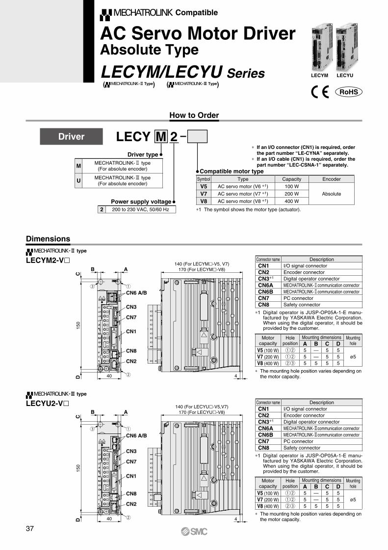
qe
w
CN2
CN8
CN1
CN7
CN3
CN6 A/B
DC
B A
150
40
140 (For LECYM-V5, V7)170 (For LECYM-V8)
4
qe
w
CN2
CN8
CN1
CN7
CN3
CN6 A/B
DC
B A
150
40
140 (For LECYU-V5,V7)170 (For LECYU-V8)
4
Compatible
AC Servo Motor DriverAbsolute Type
LECYM/LECYU Series
How to Order
Dimensions
LECYM2-Vl
LECYU2-Vl
LECY M 2Driver type
Compatible motor type
Power supply voltage*1 The symbol shows the motor type (actuator).
*1 Digital operator is JUSP-OP05A-1-E manu-factured by YASKAWA Electric Corporation. When using the digital operator, it should be provided by the customer.
* The mounting hole position varies depending on the motor capacity.
* The mounting hole position varies depending on the motor capacity.
*1 Digital operator is JUSP-OP05A-1-E manu-factured by YASKAWA Electric Corporation. When using the digital operator, it should be provided by the customer.
Driver
Connector name DescriptionCN1 I/O signal connectorCN2 Encoder connectorCN3*1 Digital operator connectorCN6A MECHATROLINK-3communication connectorCN6B MECHATROLINK-3communication connectorCN7 PC connectorCN8 Safety connector
Connector name DescriptionCN1 I/O signal connectorCN2 Encoder connectorCN3*1 Digital operator connectorCN6A MECHATROLINK-2communication connectorCN6B MECHATROLINK-2communication connectorCN7 PC connectorCN8 Safety connector
Motor capacity
Hole position
Mounting dimensions Mounting holeA B C D
V5 (100 W) qw 5 — 5 5ø5V7 (200 W) qw 5 — 5 5
V8 (400 W) we 5 5 5 5
Motor capacity
Hole position
Mounting dimensions Mounting holeA B C D
V5 (100 W) qw 5 — 5 5ø5V7 (200 W) qw 5 — 5 5
V8 (400 W) we 5 5 5 5
2 200 to 230 VAC, 50/60 Hz
M MECHATROLINK-2 type(For absolute encoder)
U MECHATROLINK-3 type(For absolute encoder)
Symbol Type Capacity Encoder
V5 AC servo motor (V6 *1) 100 W
AbsoluteV7 AC servo motor (V7 *1) 200 W
V8 AC servo motor (V8 *1) 400 W
-@ type
-# type
( -@ Type) ( -# Type)LECYM LECYU
* If an I/O connector (CN1) is required, order the part number “LE-CYNA” separately.
* If an I/O cable (CN1) is required, order the part number “LEC-CSNA-1” separately.
37
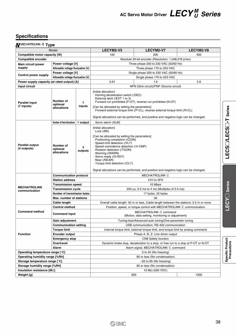
Specifications
TypeModel LECYM2-V5 LECYM2-V7 LECYM2-V8
Compatible motor capacity [W] 100 200 400
Compatible encoder Absolute 20-bit encoder (Resolution: 1,048,576 p/rev)
Main circuit power supply
Power voltage [V] Three phase 200 to 230 VAC (50/60 Hz)
Allowable voltage fluctuation [V] Three phase 170 to 253 VAC
Control power supplyPower voltage [V] Single phase 200 to 230 VAC (50/60 Hz)
Allowable voltage fluctuation [V] Single phase 170 to 253 VAC
Power supply capacity (at rated output) [A] 0.91 1.6 2.8
Input circuit NPN (Sink circuit)/PNP (Source circuit)
Parallel input(7 inputs)
Number of optional allocations
7inputs
[Initial allocation]· Homing deceleration switch (/DEC) · External latch (/EXT 1 to 3)· Forward run prohibited (P-OT), reverse run prohibited (N-OT)
[Can be allocated by setting the parameters]· Forward external torque limit (/P-CL), reverse external torque limit (/N-CL)
Signal allocations can be performed, and positive and negative logic can be changed.
Parallel output(4 outputs)
Number of fixed allocations 1 output · Servo alarm (ALM)
Number of optional allocations
3outputs
[Initial allocation]· Lock (/BK)
[Can be allocated by setting the parameters]· Positioning completion (/COIN)· Speed limit detection (/VLT)· Speed coincidence detection (/V-CMP) · Rotation detection (/TGON) · Warning (/WARN)· Servo ready (/S-RDY) · Near (/NEAR)· Torque limit detection (/CLT)
Signal allocations can be performed, and positive and negative logic can be changed.
MECHATROLINK communication
Communication protocol MECHATROLINK-2
Station address 41H to 5FH
Transmission speed 10 Mbps
Transmission cycle 250 μs, 0.5 ms to 4 ms (Multiples of 0.5 ms)
Number of transmission bytes 17 bytes, 32 bytes
Max. number of stations 30
Cable length Overall cable length: 50 m or less, Cable length between the stations: 0.5 m or more
Command method
Control method Position, speed, or torque control with MECHATROLINK-2 communication
Command input MECHATROLINK-2 command(Motion, data setting, monitoring or adjustment)
Function
Gain adjustment Tuning-less/Advanced auto tuning/One-parameter tuning
Communication setting USB communication, RS-422 communication
Torque limit Internal torque limit, external torque limit, and torque limit by analog command
Encoder output Phase A, B, Z: Line driver output
Emergency stop CN8 Safety function
Overtravel Dynamic brake stop, deceleration to a stop, or free run to a stop at P-OT or N-OT
Alarm Alarm signal, MECHATROLINK-2 command
Operating temperature range [°C] 0 to 55 (No freezing)
Operating humidity range [%RH] 90 or less (No condensation)
Storage temperature range [°C] –20 to 85 (No freezing)
Storage humidity range [%RH] 90 or less (No condensation)
Insulation resistance [MΩ] 10 MΩ (500 VDC)
Weight [g] 900 1000
-@
38
AC Servo Motor Driver LECY M U Series
LE
CS
/L
EC
S
-T S
erie
sL
EC
Y
Ser
ies
Sp
ecifi
c P
rodu
ctP
reca
utio
ns
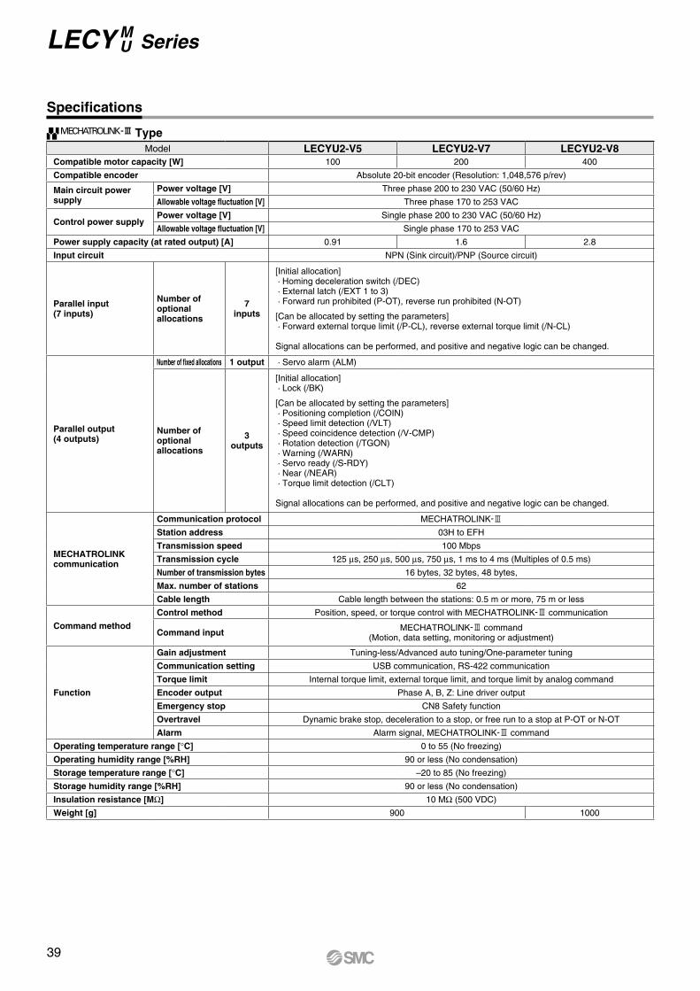
Specifications
Model LECYU2-V5 LECYU2-V7 LECYU2-V8Compatible motor capacity [W] 100 200 400
Compatible encoder Absolute 20-bit encoder (Resolution: 1,048,576 p/rev)
Main circuit power supply
Power voltage [V] Three phase 200 to 230 VAC (50/60 Hz)
Allowable voltage fluctuation [V] Three phase 170 to 253 VAC
Control power supplyPower voltage [V] Single phase 200 to 230 VAC (50/60 Hz)
Allowable voltage fluctuation [V] Single phase 170 to 253 VAC
Power supply capacity (at rated output) [A] 0.91 1.6 2.8
Input circuit NPN (Sink circuit)/PNP (Source circuit)
Parallel input(7 inputs)
Number of optional allocations
7inputs
[Initial allocation]· Homing deceleration switch (/DEC) · External latch (/EXT 1 to 3)· Forward run prohibited (P-OT), reverse run prohibited (N-OT)
[Can be allocated by setting the parameters]· Forward external torque limit (/P-CL), reverse external torque limit (/N-CL)
Signal allocations can be performed, and positive and negative logic can be changed.
Parallel output (4 outputs)
Number of fixed allocations 1 output · Servo alarm (ALM)
Number of optional allocations
3outputs
[Initial allocation]· Lock (/BK)
[Can be allocated by setting the parameters]· Positioning completion (/COIN)· Speed limit detection (/VLT)· Speed coincidence detection (/V-CMP) · Rotation detection (/TGON) · Warning (/WARN)· Servo ready (/S-RDY) · Near (/NEAR)· Torque limit detection (/CLT)
Signal allocations can be performed, and positive and negative logic can be changed.
MECHATROLINK communication
Communication protocol MECHATROLINK-3
Station address 03H to EFH
Transmission speed 100 Mbps
Transmission cycle 125 μs, 250 μs, 500 μs, 750 μs, 1 ms to 4 ms (Multiples of 0.5 ms)
Number of transmission bytes 16 bytes, 32 bytes, 48 bytes,
Max. number of stations 62
Cable length Cable length between the stations: 0.5 m or more, 75 m or less
Command method
Control method Position, speed, or torque control with MECHATROLINK-3 communication
Command input MECHATROLINK-3 command(Motion, data setting, monitoring or adjustment)
Function
Gain adjustment Tuning-less/Advanced auto tuning/One-parameter tuning
Communication setting USB communication, RS-422 communication
Torque limit Internal torque limit, external torque limit, and torque limit by analog command
Encoder output Phase A, B, Z: Line driver output
Emergency stop CN8 Safety function
Overtravel Dynamic brake stop, deceleration to a stop, or free run to a stop at P-OT or N-OT
Alarm Alarm signal, MECHATROLINK-3 command
Operating temperature range [°C] 0 to 55 (No freezing)
Operating humidity range [%RH] 90 or less (No condensation)
Storage temperature range [°C] –20 to 85 (No freezing)
Storage humidity range [%RH] 90 or less (No condensation)
Insulation resistance [MΩ] 10 MΩ (500 VDC)
Weight [g] 900 1000
Type-#
39
LECY M U Series
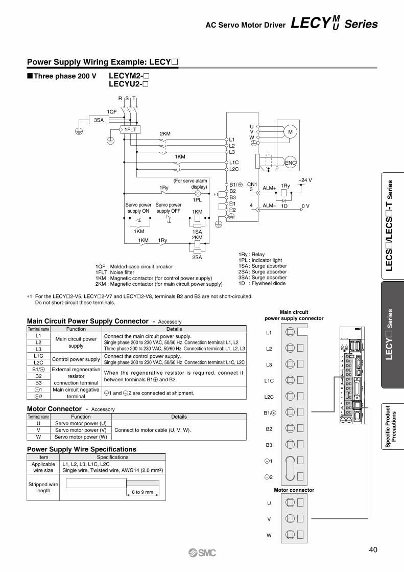
8 to 9 mm
2KM
1QF
R S T
1KM
1KM
1SA
2SA
1PL∗1
CN1ALM+
+24 V1Ry1Ry
1Ry1KM
1KM2KM
1D 0 VALM−
3
4
U
L1
V
Servo powersupply ON
Servo powersupply OFF
(For servo alarmdisplay)
M
ENC
1QF : Molded-case circuit breaker1FLT: Noise filter1KM : Magnetic contactor (for control power supply)2KM : Magnetic contactor (for main circuit power supply)
1Ry : Relay1PL : Indicator light1SA : Surge absorber2SA : Surge absorber3SA : Surge absorber1D : Flywheel diode
W
L2
L1CL2C
L3
B1/
3SA
1FLT
B2B3
12
U
V
W
L1
L2
L3
L1C
L2C
B1/
B2
B3
1
2
+
−
−
Main circuitpower supply connector
Motor connector
Power Supply Wiring Example: LECYlThree phase 200 V LECYM2-l
LECYU2-l
Main Circuit Power Supply Connector * Accessory
*1 For the LECYl2-V5, LECYl2-V7 and LECYl2-V8, terminals B2 and B3 are not short-circuited. Do not short-circuit these terminals.
Motor Connector * Accessory
Power Supply Wire SpecificationsItem Specifications
Applicable wire size
L1, L2, L3, L1C, L2CSingle wire, Twisted wire, AWG14 (2.0 mm2)
Stripped wire length
Terminal name Function DetailsU Servo motor power (U)
Connect to motor cable (U, V, W).V Servo motor power (V)W Servo motor power (W)
Terminal name Function DetailsL1
Main circuit power supply
Connect the main circuit power supply.Single phase 200 to 230 VAC, 50/60 Hz Connection terminal: L1, L2Three phase 200 to 230 VAC, 50/60 Hz Connection terminal: L1, L2, L3
L2L3
L1CControl power supply
Connect the control power supply.Single phase 200 to 230 VAC, 50/60 Hz Connection terminal: L1C, L2CL2C
B1/ + External regenerative resistor
connection terminal
When the regenerative resistor is required, connect it between terminals B1 + and B2.
B2B3− 1 Main circuit negative
terminal− 1 and − 2 are connected at shipment.
− 2
40
AC Servo Motor Driver LECY M U Series
LE
CS
/L
EC
S
-T S
erie
sL
EC
Y
Ser
ies
Sp
ecifi
c P
rodu
ctP
reca
utio
ns
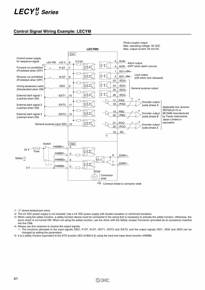
Encoder outputpulse phase A
Control power supplyfor sequence signal +24 VIN 6 3 ALM+
4 ALM–
1 SO1+/BK+
2 SO1–/BK–
23 /SO2+
24 /SO2–
25 /SO3+
26 /SO3–
3.3 kΩ+24 V
CN1
CN84
7P-OT
8N-OT
9/DEC
10/EXT1
11/EXT2
12
13
/EXT3
∗2
General purpose input /SIO
∗1
Alarm output(OFF when alarm occurs)
Lock output(ON when lock released)
General purpose output
LECYM2
Fuse
Safety ∗3
∗5
0 V
24 V
Switch/HWBB1+
3/HWBB1–
6
Driver
FG
7
8
EDM1–
EDM1+
/HWBB2+
5/HWBB2–
Forward run prohibited(Prohibited when OFF)
Reverse run prohibited(Prohibited when OFF)
Homing deceleration switch(Decelerated when ON)
External latch signal 1(Latched when ON)
External latch signal 2(Latched when ON)
External latch signal 3(Latched when ON)
Photo-coupler outputMax. operating voltage: 30 VDCMax. output current: 50 mA DC
Applicable line receiver:SN75ALS175 orMC3486 manufacturedby Texas Instruments Japan Limited or equivalent
Connect shield to connector shell.
PAO ∗4
/PAO1718
Encoder outputpulse phase B
PBO ∗4
/PBO1920
Encoder outputpulse phase Z
PCO ∗4
/PCO
SG
2122
16
Connectorshell
Control Signal Wiring Example: LECYM
*1 shows twisted-pair wires.*2 The 24 VDC power supply is not included. Use a 24 VDC power supply with double insulation or reinforced insulation.*3 When using the safety function, a safety function device must be connected to the wiring that is necessary to activate the safety function. Otherwise, the
servo motor is not turned ON. When not using the safety function, use the driver with the Safety Jumper Connector (provided as an accessory) inserted into the CN8.
*4 Always use line receivers to receive the output signals.** The functions allocated to the input signals /DEC, P-OT, N-OT, /EXT1, /EXT2 and /EXT3, and the output signals /SO1, /SO2 and /SO3 can be
changed by setting the parameters.*5 It is a safety function equivalent to the STO function (IEC 61800-5-2) using the hard wire base block function (HWBB).
41
LECY M U Series
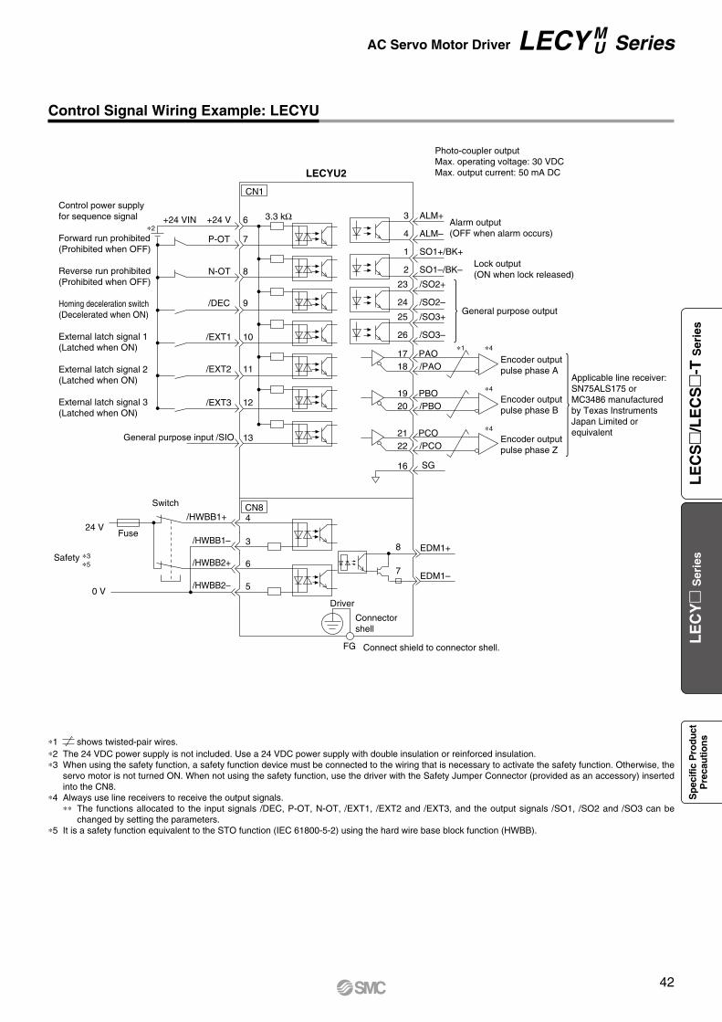
Encoder outputpulse phase A
Control power supplyfor sequence signal +24 VIN 6 3 ALM+
4 ALM–
1 SO1+/BK+
2 SO1–/BK–
23 /SO2+
24 /SO2–
25 /SO3+
26 /SO3–
3.3 kΩ+24 V
CN1
CN84
7P-OT
8N-OT
9/DEC
10/EXT1
11/EXT2
12
13
/EXT3
∗2
/SIO
Alarm output(OFF when alarm occurs)
LECYU2
Fuse
0 V
24 V
Switch
/HWBB1+
3/HWBB1–
6
Driver
FG
7
8
EDM1–
EDM1+
/HWBB2+
5/HWBB2–
Forward run prohibited(Prohibited when OFF)
Reverse run prohibited(Prohibited when OFF)
Homing deceleration switch(Decelerated when ON)
External latch signal 1(Latched when ON)
External latch signal 2(Latched when ON)
External latch signal 3(Latched when ON)
Photo-coupler outputMax. operating voltage: 30 VDCMax. output current: 50 mA DC
Applicable line receiver:SN75ALS175 orMC3486 manufacturedby Texas Instruments Japan Limited or equivalent
Connect shield to connector shell.
PAO∗4
/PAO1718
Encoder outputpulse phase B
PBO ∗4
/PBO1920
Encoder outputpulse phase Z
PCO ∗4
/PCO
SG
2122
16
General purpose input
∗1
Lock output(ON when lock released)
General purpose output
Connectorshell
Safety ∗3
∗5
Control Signal Wiring Example: LECYU
*1 shows twisted-pair wires.*2 The 24 VDC power supply is not included. Use a 24 VDC power supply with double insulation or reinforced insulation.*3 When using the safety function, a safety function device must be connected to the wiring that is necessary to activate the safety function. Otherwise, the
servo motor is not turned ON. When not using the safety function, use the driver with the Safety Jumper Connector (provided as an accessory) inserted into the CN8.
*4 Always use line receivers to receive the output signals.** The functions allocated to the input signals /DEC, P-OT, N-OT, /EXT1, /EXT2 and /EXT3, and the output signals /SO1, /SO2 and /SO3 can be
changed by setting the parameters. *5 It is a safety function equivalent to the STO function (IEC 61800-5-2) using the hard wire base block function (HWBB).
42
AC Servo Motor Driver LECY M U Series
LE
CS
/L
EC
S
-T S
erie
sL
EC
Y
Ser
ies
Sp
ecifi
c P
rodu
ctP
reca
utio
ns
G
W
V
U
L 50
M4 Crimped terminal
ø7
L 50
ø7
3-M4 Crimped terminal
L
øD
(60) (100)
Battery caseDepth dimension: 25 mm
(7)
(32)
19
12
531
642
25
Product no. øD
LE-CYE-SlA 6.5
LE-CYE-RlA 6.8
Options
Motor cable, Motor cable for lock option, Encoder cable (LECYM/LECYU common)
Cable type
Cable description
Motor type
Cable length (L) [m]
LE CY M S 5 AMotor capacity
5
* The cable entry direction is axis side only.
* For encoder cable, the suffix “–l” (Motor capacity) is not necessary.
LE-CYM-llA-l: Motor cable
LE-CYB-llA-l: Motor cable for lock option
LE-CYE-llA: Encoder cable
Direction of connector
A
Axis side
5 100 W7 200/400 W
3 35 5A 10C 20
S Standard cableR Robotic cable
Y AC servo motor
M Motor cableB Motor cable for lock option
E Encoder cable(With battery case)
WeightProduct no. Length [m] Weight [g] Note
LE-CYM-S3A-5 3 250
100 WLE-CYM-S5A-5 5 390LE-CYM-SAA-5 10 750LE-CYM-SCA-5 20 1500LE-CYM-S3A-7 3 250
200/400 W
LE-CYM-S5A-7 5 390LE-CYM-SAA-7 10 750LE-CYM-SCA-7 20 1500LE-CYM-R3A-5 3 220
100 WLE-CYM-R5A-5 5 350LE-CYM-RAA-5 10 670LE-CYM-RCA-5 20 1300LE-CYM-R3A-7 3 220
200/400 W
LE-CYM-R5A-7 5 350LE-CYM-RAA-7 10 670LE-CYM-RCA-7 20 1300
WeightProduct no. Length [m] Weight [g] Note
LE-CYB-S3A-5 3 240
100 WLE-CYB-S5A-5 5 390LE-CYB-SAA-5 10 750LE-CYB-SCA-5 20 1490LE-CYB-S3A-7 3 240
200/400 W
LE-CYB-S5A-7 5 390LE-CYB-SAA-7 10 750LE-CYB-SCA-7 20 1490LE-CYB-R3A-5 3 220
100 WLE-CYB-R5A-5 5 350LE-CYB-RAA-5 10 670LE-CYB-RCA-5 20 1300LE-CYB-R3A-7 3 220
200/400 W
LE-CYB-R5A-7 5 350LE-CYB-RAA-7 10 670LE-CYB-RCA-7 20 1300
WeightProduct no. Length [m] Weight [g]
LE-CYE-S3A 3 230LE-CYE-S5A 5 360LE-CYE-SAA 10 680LE-CYE-SCA 20 1250LE-CYE-R3A 3 220LE-CYE-R5A 5 330LE-CYE-RAA 10 660LE-CYE-RCA 20 1240
* LE-CYM-SlA-l is JZSP-CSM0l-ll-E manufactured by YASKAWA CONTROLS CO., LTD.LE-CYB-SlA-l is JZSP-CSM1l-ll-E manufactured by YASKAWA CONTROLS CO., LTD.LE-CYE-SlA is JZSP-CSP05-ll-E manufactured by YASKAWA CONTROLS CO., LTD.
LE-CYM-RlA-l is JZSP-CSM2l-ll-E manufactured by YASKAWA CONTROLS CO., LTD.LE-CYB-RlA-l is JZSP-CSM3l-ll-E manufactured by YASKAWA CONTROLS CO., LTD.LE-CYE-RlA is JZSP-CSP25-ll-E manufactured by YASKAWA CONTROLS CO., LTD.
43
LECY M U Series
WeightProduct no. Weight [g]LE-CYNA 25
WeightProduct no. Weight [g]
LEC-CSNA-1 303
39
37.2
Options
I/O connector (Without cable, Connector only)
LE-CYNA
Driver type
LE CYN A
* LE-CYNA: 10126-3000PE (connector)/10326-52F0-008 (shell kit) manufactured by 3M Japan Limited or equivalent* Conductor size: AWG24 to 30
A For LECYM2, LECYU2
Name plate + Lot. No.
A side B side
UT
W
H
Pin 1
Pin no. n
1500
80100
PLC, etc. sideDriver side
90 15
øD
WiringLEC-CSNA-1: Pin nos. 1 to 26
I/O cable
* LEC-CSNA-1: 10126-3000PE (connector)/10326-52F0-008 (shell kit) manufactured by 3M Japan Limited or equivalent
* Conductor size: AWG24
Connectorpin no.
Pair no. of wire
Insulationcolor Dot mark Dot
color
A s
ide
11 Orange
Red2 Black3
2 Light gray
Red4 Black5
3 WhiteRed
6 Black7
4 YellowRed
8 Black9
5 PinkRed
10 Black
Connectorpin no.
Pair no. of wire
Insulationcolor Dot mark Dot
color
A s
ide
116 Orange
Red12 Black13
7 Light gray
Red14 Black15
8 WhiteRed
16 Black17
9 YellowRed
18 Black19
10 PinkRed
20 Black
Connectorpin no.
Pair no. of wire
Insulationcolor Dot mark Dot
color
A s
ide
2111 Orange
Red22 Black23
12 Light gray
Red24 Black25
13 WhiteRed
26 Black
Dimensions/Pin No.Product no. W H T U Pin no. n
LEC-CSNA-1 39 37.2 12.7 14 14
Cable O.D.Product no. øDLEC-CSNA-1 11.1
1 1.5
Driver type
LEC CSN
A For LECYM2, LECYU2 Cable length (L) [m]
1A
44
AC Servo Motor Driver LECY M U Series
LE
CS
/L
EC
S
-T S
erie
sL
EC
Y
Ser
ies
Sp
ecifi
c P
rodu
ctP
reca
utio
ns
ø416
L
46
19
L33
10.711
ø4.
8
16
46
19
Options
1
* LEC-CYM-l is JEPMC-W6002-ll-E manufactured by YASKAWA CONTROLS CO., LTD.* LEC-CYU-l is JEPMC-W6012-ll-E manufactured by YASKAWA CONTROLS CO., LTD.
* LEC-CYRM is JEPMC-W6022-E manufactured by YASKAWA CONTROLS CO., LTD.
Cable length (L)
*1 Not available for the MECHATROLINK-2cable
MLEC YCMotor type
Cable description
LEC CYRM
M MECHATROLINK-2cableU MECHATROLINK-3cable
Y AC servo motor L*1 0.2 mJ 0.5 m1 1 m3 3 m
cable-@
cable type
Terminating connector for -@
cable-#
Weight: 10 g
WeightProduct no. Length [m] Weight [g]
LE-CYM-J 0.5 50
LE-CYM-1 1 80
LE-CYM-3 3 200
WeightProduct no. Length [m] Weight [g]
LE-CYU-L 0.2 21
LE-CYU-J 0.5 41
LE-CYU-1 1 75
LE-CYU-3 3 205
45
LECY M U Series
250010 to 20
(100)
ø4.
0
(55)
(33) 3000(20)
ø6
Options
USB cable (2.5 m)
Battery (LECYM/LECYU common)
LEC JZ
JZ
CVUSB
CVBATLEC
Compatible PC
Hardware Requirements
When using setup software (SigmaWin+TM), use an IBM PC/AT compatible PC that meets the following operating conditions.
Cable for connecting PC and driver when using the setupsoftware (SigmaWin+TM)Do not use any cable other than this cable.
Setup software (SigmaWin+TM) (LECYM/LECYU common)* Please download the SigmaWin+TM via our website.
SigmaWin+TM is a registered trademark or trademark of YASKAWA Electric Corporation.
* JZSP-BA01 manufactured by YASKAWA CONTROLS CO., LTD.
* JZSP-CVS06-02-E manufactured by YASKAWA CONTROLS CO., LTD.
Cable for safety function device (3 m)
LEC JZ CVSAFCable for connecting the driver and devicewhen using the safety functionDo not use any cable other than this cable.
* JZSP-CVH03-03-E manufactured by YASKAWA CONTROLS CO., LTD.
Drivers
USB cable
PC
LECYM2 LECYU2
Battery for replacementAbsolute position data is maintained by installing the battery to the battery case of the encoder cable.
Adjustment, waveform display, parameter read/write, and test operation can be performed upon a PC.
*1 Windows, Windows Vista®, Windows® 7 are registered trademarks of Microsoft Corporation in the United States and/or other countries.*2 On some PCs, this software may not run properly.*3 Not compatible with 64-bit Windows® XP and 64-bit Windows Vista®
*4 For Windows® XP, please use it by the administrator authority (When installing and using it.).*5 In PC that uses the program to correct the problem of HotfixQ328310, it is likely to fail in the installation. In that case, please use the program to correct
the problem of HotfixQ329623.*6 Order USB cable separately.
Equipment Setup software (SigmaWin+TM)
*1, 2, 3, 4PC
OS Windows® XP*5, Windows Vista®, Windows® 7 (32-bit/64-bit)Available HD space 350 MB or more (When the software is installed, 400 MB or more is recommended.)Communication interface Use USB port.
DisplayXVGA monitor (1024 x 768 or more, “The small font is used.”)
256 color or more (65536 color or more is recommended.)Connectable with the PC above
Keyboard Connectable with the PC aboveMouse Connectable with the PC abovePrinter Connectable with the PC aboveUSB cable LEC-JZ-CVUSB*6
Other Adobe Reader Ver. 5.0 or higher (* Except Ver. 6.0)
* The LEC-JZ-CVBAT is a single battery that uses lithium metal battery ER3V.When transporting lithium metal batteries and devices with built-in lithium metal batteries by a method subject to UN regulations, it is necessary to apply measures according to the regulations stipulated in the United Nations Recommendations on the Transport of Dangerous Goods, the Technical Instructions (ICAO-TI) of the International Civil Aviation Organization (ICAO), and the International Maritime Dangerous Goods Code (IMDG CODE) of the International Maritime Organization (IMO). If a customer is transporting products such as shown above, it is necessary to confirm the latest regulations, or the laws and regulations of the country of transport on your own, in order to apply the proper measures. Please contact SMC sales representative for details.
Weight: 10 g
Weight: 150 g
Weight: 160 g
46
AC Servo Motor Driver LECY M U Series
LE
CS
/L
EC
S
-T S
erie
sL
EC
Y
Ser
ies
Sp
ecifi
c P
rodu
ctP
reca
utio
ns

Design / Selection
Handling
Handling
9. Static electricity may cause malfunction or break the driver. Do not touch the driver while power is sup-plied.When touching the driver for maintenance, take sufficient meas-ures to eliminate static electricity.
10. Do not use the product in an area where dust, powder dust, water, chemicals, or oil is in the air.It will cause failure or malfunction.
11. Do not use the product in an area where a magnetic field is generated.It will cause failure or malfunction.
12. Do not install the product in an environment contain-ing flammable gas, explosive gas, or corrosive gas.It could lead to fire, explosion, or corrosion.
13. Radiant heat from strong heat sources, such as a fur-nace, direct sunlight, etc., should not be applied to the product.It will cause failure of the driver or its peripheral devices.
14. Do not use the product in an environment subject to a temperature cycle.It will cause failure of the driver or its peripheral devices.
15. Do not use the product in a place where surges are generated.When there are units that generate a large amount of surge around the product (e.g. solenoid type lifters, high-frequency in-duction furnaces, motors, etc.), this may cause deterioration or damage to the product’s internal circuit. Avoid sources of surge generation and crossed lines.
16. Do not install the product in an environment under the effect of vibrations and impacts.It will cause failure or malfunction.
17. When a surge-generating load, such as a relay or so-lenoid valve, is driven directly, use a product that in-corporates a surge absorption element.
Installation
1. Install the driver and its peripheral devices on a fire-proof material.Direct installation on or near a flammable material may cause a fire.
2. Do not install the product in a place subject to vibra-tions and impacts.It will cause failure or malfunction.
3. The driver should be mounted on a vertical wall in a vertical direction. Also, be sure not to cover the driver’s suction/exhaust ports.
4. Install the driver and its peripheral devices on a flat surface.If the mounting surface is distorted or uneven, an unacceptable force may be added to the housing, etc., causing problems.
LECS/LECS-T/LECY SeriesSpecific Product Precautions 1Be sure to read this before handling the products. For safety instructions and electric actuator precautions, refer to the “Handling Precautions for SMC Products” and the “Operation Manual” on the SMC website: https://www.smcworld.com
Warning Warning1. Be sure to apply the specified voltage.
Otherwise, malfunction or breakage may occur. If the applied volt-age is lower than the specified voltage, it is possible that the load will not be able to be moved due to an internal voltage drop of the driver. Please check the operating voltage before use.
2. Do not operate the product beyond the specifications.Otherwise, a fire, malfunction, or actuator damage may result. Please check the specifications before use.
3. Install an emergency stop circuit.Please install an emergency stop outside of the enclosure so that the system operation can be stopped immediately and the power supply can be intercepted.
4. In order to prevent any damage caused by the break-down or malfunction of the driver and its peripheral devices, a backup system should be established in ad-vance by giving a multiple-layered structure or a fail-safe design to the equipment, etc.
5. If a danger of human injury is expected due to abnor-mal heat generation, smoking, ignition, etc., of the driver and its peripheral devices, cut off the power supply of the product and the system immediately.
6. The parameters of the driver are set to initial values.Please change the parameters according to the specifi-cations of the customer’s equipment before use. Refer to the operation manual for parameter details.
Warning
Warning
1. Do not touch the inside of the driver and its peripheral devices.Doing so may cause an electric shock or damage to the driver.
2. Do not perform the operation or setting of the product with wet hands.Doing so may cause an electric shock.
3. Products with damage or those missing any compo-nents should not be used.An electric shock, fire, or injury may result.
4. Use only the specified combination between the elec-tric actuator and driver.Failure to do so may cause damage to the actuator or the driver.
5. Be careful not to be hit by workpieces while the actua-tor is moving.It may cause an injury.
6. Do not connect the power supply or power on the product before confirming the area to which the work-piece moves is safe.The movement of the workpiece may cause an accident.
7. Do not touch the product when it is energized and for some time after power has been disconnected, as it is very hot.Doing so may lead to a burn due to the high temperature.
8. Before installation, wiring, and maintenance, the volt-age should be checked with a tester 5 minutes after the power supply has been turned off.Otherwise, an electric shock, fire, or injury may result.
47
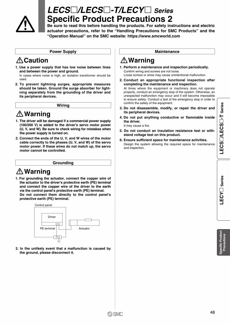
MaintenancePower Supply
LECS/LECS-T/LECY SeriesSpecific Product Precautions 2Be sure to read this before handling the products. For safety instructions and electric actuator precautions, refer to the “Handling Precautions for SMC Products” and the “Operation Manual” on the SMC website: https://www.smcworld.com
Caution1. Use a power supply that has low noise between lines
and between the power and ground.In cases where noise is high, an isolation transformer should be used.
2. To prevent lightning surges, appropriate measures should be taken. Ground the surge absorber for light-ning separately from the grounding of the driver and its peripheral devices.
1. The driver will be damaged if a commercial power supply (100/200 V) is added to the driver
,s servo motor power
(U, V, and W). Be sure to check wiring for mistakes when the power supply is turned on.
2. Connect the ends of the U, V, and W wires of the motor cable correctly to the phases (U, V, and W) of the servo motor power. If these wires do not match up, the servo motor cannot be controlled.
WarningWiring
Driver
Control panel
PE terminal Actuator
1. For grounding the actuator, connect the copper wire of the actuator to the driver,s protective earth (PE) terminal and connect the copper wire of the driver to the earth via the control panel,s protective earth (PE) terminal.Do not connect them directly to the control panel,s protective earth (PE) terminal.
2. In the unlikely event that a malfunction is caused by the ground, please disconnect it.
WarningGrounding
Warning1. Perform a maintenance and inspection periodically.
Confirm wiring and screws are not loose. Loose screws or wires may cause unintentional malfunction.
2. Conduct an appropriate functional inspection after completing the maintenance and inspection.At times where the equipment or machinery does not operate properly, conduct an emergency stop of the system. Otherwise, an unexpected malfunction may occur and it will become impossible to ensure safety. Conduct a test of the emergency stop in order to confirm the safety of the equipment.
3. Do not disassemble, modify, or repair the driver and its peripheral devices.
4. Do not put anything conductive or flammable inside the driver.It may cause a fire.
5. Do not conduct an insulation resistance test or with-stand voltage test on this product.
6. Ensure sufficient space for maintenance activities.Design the system allowing the required space for maintenance and inspection.
48
LE
CS
/L
EC
S
-T S
erie
sL
EC
Y
Ser
ies
Sp
ecifi
c P
rodu
ctP
reca
utio
ns

Safety Instructions Be sure to read the “Handling Precautions for SMC Products” (M-E03-3) and “Operation Manual” before use.