Embed Size (px)
Citation preview
www.schneider-electric.com0198
4411
1376
1, V
1.05
, 12.
2010
LXM32CAC servo driveProduct manualV1.05, 12.2010
2 AC servo drive
Important information LXM32C
0198
4411
1376
1, V
1.05
, 12.
2010
Important information
This manual is part of the product.
Carefully read this manual and observe all instructions.
Keep this manual for future reference.
Hand this manual and all other pertinent product documentation over to all users of the product.
Carefully read and observe all safety instructions and the chapter "Be-fore you begin - safety information".
Some products are not available in all countries.For information on the availability of products, please consult the cata-log.
Subject to technical modifications without notice.
All details provided are technical data which do not constitute warranted qualities.
Most of the product designations are registered trademarks of their re-spective owners, even if this is not explicitly indicated.

0198
4411
1376
1, V
1.05
, 12.
2010
LXM32C Table of contents
AC servo drive 3
Table of contents
Important information. . . . . . . . . . . . . . . . . . . . . . . . . . . . . . . . . 2
Table of contents . . . . . . . . . . . . . . . . . . . . . . . . . . . . . . . . . . . . 3
About this manual. . . . . . . . . . . . . . . . . . . . . . . . . . . . . . . . . . . . 9
Further reading . . . . . . . . . . . . . . . . . . . . . . . . . . . . . . . . . . . . . . 10
1 Introduction . . . . . . . . . . . . . . . . . . . . . . . . . . . . . . . . . . . . . . . . 11
1.1 Device overview . . . . . . . . . . . . . . . . . . . . . . . . . . . . . . 11
1.2 Components and interfaces . . . . . . . . . . . . . . . . . . . . . 12
1.3 Type code . . . . . . . . . . . . . . . . . . . . . . . . . . . . . . . . . . . 13
2 Before you begin - safety information. . . . . . . . . . . . . . . . . . . 15
2.1 Qualification of personnel . . . . . . . . . . . . . . . . . . . . . . . 15
2.2 Intended use . . . . . . . . . . . . . . . . . . . . . . . . . . . . . . . . . 15
2.3 Hazard categories . . . . . . . . . . . . . . . . . . . . . . . . . . . . . 16
2.4 Basic information. . . . . . . . . . . . . . . . . . . . . . . . . . . . . . 17
2.5 DC bus voltage measurement . . . . . . . . . . . . . . . . . . . . 19
2.6 Functional safety . . . . . . . . . . . . . . . . . . . . . . . . . . . . . . 19
2.7 Standards and terminology . . . . . . . . . . . . . . . . . . . . . . 19
3 Technical Data . . . . . . . . . . . . . . . . . . . . . . . . . . . . . . . . . . . . . . 21
3.1 Ambient conditions . . . . . . . . . . . . . . . . . . . . . . . . . . . . 21
3.2 Mechanical data . . . . . . . . . . . . . . . . . . . . . . . . . . . . . . 233.2.1 Dimensional drawings. . . . . . . . . . . . . . . . . . . . . . . . 23
3.3 Electrical Data . . . . . . . . . . . . . . . . . . . . . . . . . . . . . . . . 253.3.1 Power stage . . . . . . . . . . . . . . . . . . . . . . . . . . . . . . . 253.3.2 Controller supply voltage 24V. . . . . . . . . . . . . . . . . . 343.3.3 Signals . . . . . . . . . . . . . . . . . . . . . . . . . . . . . . . . . . . 353.3.4 Functional safety. . . . . . . . . . . . . . . . . . . . . . . . . . . . 433.3.5 Braking resistor. . . . . . . . . . . . . . . . . . . . . . . . . . . . . 443.3.6 Internal mains filter . . . . . . . . . . . . . . . . . . . . . . . . . . 483.3.7 External mains filters (accessories) . . . . . . . . . . . . . 493.3.8 Mains reactor (accessory) . . . . . . . . . . . . . . . . . . . . 50
3.4 Conditions for UL 508C and CSA . . . . . . . . . . . . . . . . . 51
3.5 Certifications . . . . . . . . . . . . . . . . . . . . . . . . . . . . . . . . . 51
3.6 Declaration of conformity. . . . . . . . . . . . . . . . . . . . . . . . 52

4 AC servo drive
Table of contents LXM32C
0198
4411
1376
1, V
1.05
, 12.
2010
3.7 TÜV certificate for functional safety . . . . . . . . . . . . . . . 53
4 Basics . . . . . . . . . . . . . . . . . . . . . . . . . . . . . . . . . . . . . . . . . . . . . 55
4.1 Functional safety. . . . . . . . . . . . . . . . . . . . . . . . . . . . . . 55
5 Engineering. . . . . . . . . . . . . . . . . . . . . . . . . . . . . . . . . . . . . . . . . 57
5.1 Electromagnetic compatibility, EMC . . . . . . . . . . . . . . . 58
5.2 Cables . . . . . . . . . . . . . . . . . . . . . . . . . . . . . . . . . . . . . 625.2.1 Overview of the required cables. . . . . . . . . . . . . . . . 63
5.3 Residual current device . . . . . . . . . . . . . . . . . . . . . . . . 65
5.4 Operation in an IT mains . . . . . . . . . . . . . . . . . . . . . . . 65
5.5 Parallel connection DC bus . . . . . . . . . . . . . . . . . . . . . 66
5.6 Mains reactor . . . . . . . . . . . . . . . . . . . . . . . . . . . . . . . . 67
5.7 Mains filter . . . . . . . . . . . . . . . . . . . . . . . . . . . . . . . . . . 685.7.1 Deactivating the Y capacitors . . . . . . . . . . . . . . . . . 69
5.8 Rating the braking resistor . . . . . . . . . . . . . . . . . . . . . . 705.8.1 Internal braking resistor . . . . . . . . . . . . . . . . . . . . . . 715.8.2 External braking resistor . . . . . . . . . . . . . . . . . . . . . 725.8.3 Rating information . . . . . . . . . . . . . . . . . . . . . . . . . . 73
5.9 Safety function STO ("Safe Torque Off"). . . . . . . . . . . . 775.9.1 Definitions . . . . . . . . . . . . . . . . . . . . . . . . . . . . . . . . 775.9.2 Function . . . . . . . . . . . . . . . . . . . . . . . . . . . . . . . . . . 775.9.3 Requirements for using the safety function . . . . . . . 785.9.4 Application examples STO. . . . . . . . . . . . . . . . . . . . 80
5.10 Logic type . . . . . . . . . . . . . . . . . . . . . . . . . . . . . . . . . . . 82
5.11 Monitoring functions . . . . . . . . . . . . . . . . . . . . . . . . . . . 83
5.12 Configurable inputs and outputs . . . . . . . . . . . . . . . . . . 84
6 Installation. . . . . . . . . . . . . . . . . . . . . . . . . . . . . . . . . . . . . . . . . . 85
6.1 Mechanical installation . . . . . . . . . . . . . . . . . . . . . . . . . 866.1.1 Mounting the device. . . . . . . . . . . . . . . . . . . . . . . . . 876.1.2 Mounting mains filter, mains reactor and braking
resistor . . . . . . . . . . . . . . . . . . . . . . . . . . . . . . . . . . . 89
6.2 Electrical installation . . . . . . . . . . . . . . . . . . . . . . . . . . . 916.2.1 Overview of procedure. . . . . . . . . . . . . . . . . . . . . . . 926.2.2 Connection overview . . . . . . . . . . . . . . . . . . . . . . . . 936.2.3 Connection grounding screw . . . . . . . . . . . . . . . . . . 946.2.4 Connecting the motor phases (CN 10, motor) . . . . . 956.2.5 Holding brake connection (CN11, Brake). . . . . . . . 1016.2.6 Connecting the DC bus (CN9, DC bus) . . . . . . . . . 1026.2.7 Braking resistor connection (CN8, Braking
Resistor). . . . . . . . . . . . . . . . . . . . . . . . . . . . . . . . . 1036.2.8 Connection of power stage supply voltage (CN1) . 1066.2.9 Connecting the motor encoder (CN3) . . . . . . . . . . 1116.2.10 Connection PTO (CN4, Pulse Train Out) . . . . . . . . 1136.2.11 Connection PTI (CN5, Pulse Train In) . . . . . . . . . . 115

0198
4411
1376
1, V
1.05
, 12.
2010
LXM32C Table of contents
AC servo drive 5
6.2.12 Connection the controller supply voltage andSTO (CN2, DC Supply and STO) . . . . . . . . . . . . . . 118
6.2.13 Connecting the analog inputs (CN6). . . . . . . . . . . . 1216.2.14 Connecting the digital inputs/outputs (CN6) . . . . . . 1236.2.15 Connection of PC with commissioning software
CN7) . . . . . . . . . . . . . . . . . . . . . . . . . . . . . . . . . . . . 125
6.3 Checking installation . . . . . . . . . . . . . . . . . . . . . . . . . . 127
7 Commissioning . . . . . . . . . . . . . . . . . . . . . . . . . . . . . . . . . . . . 129
7.1 Basic information. . . . . . . . . . . . . . . . . . . . . . . . . . . . . 129
7.2 Overview . . . . . . . . . . . . . . . . . . . . . . . . . . . . . . . . . . . 1317.2.1 Commissioning steps . . . . . . . . . . . . . . . . . . . . . . . 1317.2.2 Commissioning tools. . . . . . . . . . . . . . . . . . . . . . . . 131
7.3 Integrated HMI. . . . . . . . . . . . . . . . . . . . . . . . . . . . . . . 1327.3.1 Indication and operation . . . . . . . . . . . . . . . . . . . . . 1337.3.2 Menu structure . . . . . . . . . . . . . . . . . . . . . . . . . . . . 1347.3.3 Making settings. . . . . . . . . . . . . . . . . . . . . . . . . . . . 140
7.4 External graphic display terminal . . . . . . . . . . . . . . . . 1427.4.1 Display and controls . . . . . . . . . . . . . . . . . . . . . . . . 1437.4.2 Connecting the external graphic display terminal
to LXM32 . . . . . . . . . . . . . . . . . . . . . . . . . . . . . . . . 1447.4.3 Using the external graphic display terminal . . . . . . 144
7.5 Commissioning software . . . . . . . . . . . . . . . . . . . . . . . 146
7.6 Commissioning procedure. . . . . . . . . . . . . . . . . . . . . . 1477.6.1 Switching on the device for the first time . . . . . . . . 1487.6.2 Operating state (state diagram) . . . . . . . . . . . . . . . 1497.6.3 Setting basic parameters and limit values . . . . . . . 1507.6.4 Analog inputs . . . . . . . . . . . . . . . . . . . . . . . . . . . . . 1547.6.5 Digital inputs / outputs . . . . . . . . . . . . . . . . . . . . . . 1567.6.6 Testing the safety function STO . . . . . . . . . . . . . . . 1587.6.7 Holding brake . . . . . . . . . . . . . . . . . . . . . . . . . . . . . 1597.6.8 Checking the direction of movement. . . . . . . . . . . . 1627.6.9 Setting parameters for encoder . . . . . . . . . . . . . . . 1647.6.10 Setting the braking resistor parameters . . . . . . . . . 1687.6.11 Autotuning the device . . . . . . . . . . . . . . . . . . . . . . . 1707.6.12 Enhanced settings for autotuning . . . . . . . . . . . . . . 173
7.7 Controller optimization with step response . . . . . . . . . 1757.7.1 Controller structure . . . . . . . . . . . . . . . . . . . . . . . . . 1757.7.2 Optimization . . . . . . . . . . . . . . . . . . . . . . . . . . . . . . 1767.7.3 Optimizing the velocity controller . . . . . . . . . . . . . . 1777.7.4 Checking and optimizing default settings . . . . . . . . 1827.7.5 Optimizing the position controller . . . . . . . . . . . . . . 183
7.8 Memory Card . . . . . . . . . . . . . . . . . . . . . . . . . . . . . . . 1857.8.1 Data exchange with the memory card . . . . . . . . . . 187
7.9 Duplicating existing device settings. . . . . . . . . . . . . . . 188
8 Operation . . . . . . . . . . . . . . . . . . . . . . . . . . . . . . . . . . . . . . . . . 189
8.1 Access channels . . . . . . . . . . . . . . . . . . . . . . . . . . . . . 191
6 AC servo drive
Table of contents LXM32C
0198
4411
1376
1, V
1.05
, 12.
2010
8.2 Operating states . . . . . . . . . . . . . . . . . . . . . . . . . . . . . 1938.2.1 State diagram. . . . . . . . . . . . . . . . . . . . . . . . . . . . . 1938.2.2 State transitions . . . . . . . . . . . . . . . . . . . . . . . . . . . 1958.2.3 Indication of the operating state. . . . . . . . . . . . . . . 1968.2.4 Changing the operating state. . . . . . . . . . . . . . . . . 197
8.3 Operating modes . . . . . . . . . . . . . . . . . . . . . . . . . . . . 1988.3.1 Starting the operating mode . . . . . . . . . . . . . . . . . 1988.3.2 Changing the operating mode . . . . . . . . . . . . . . . . 1988.3.3 Operating mode Jog . . . . . . . . . . . . . . . . . . . . . . . 2008.3.4 Operating mode Electronic Gear . . . . . . . . . . . . . . 2068.3.5 Operating mode Profile Torque . . . . . . . . . . . . . . . 2158.3.6 Operating mode Profile Velocity. . . . . . . . . . . . . . . 221
8.4 Movement range. . . . . . . . . . . . . . . . . . . . . . . . . . . . . 2258.4.1 Scaling . . . . . . . . . . . . . . . . . . . . . . . . . . . . . . . . . . 226
8.5 Extended settings . . . . . . . . . . . . . . . . . . . . . . . . . . . . 2308.5.1 Setting the PTO interface. . . . . . . . . . . . . . . . . . . . 2308.5.2 Setting the digital signal inputs and signal outputs 2318.5.3 Setting the motion profile for the velocity . . . . . . . . 2438.5.4 Setting the controller parameters. . . . . . . . . . . . . . 2458.5.5 Settings of parameter _DCOMstatus . . . . . . . . . . . 261
8.6 Functions for target value processing. . . . . . . . . . . . . 2628.6.1 Stop movement with Halt . . . . . . . . . . . . . . . . . . . . 2628.6.2 Stopping a movement with Quick Stop . . . . . . . . . 2648.6.3 Inverting the analog signal inputs . . . . . . . . . . . . . 2658.6.4 Limitation of the velocity via signal inputs . . . . . . . 2668.6.5 Limitation of the current via signal inputs. . . . . . . . 2688.6.6 Jerk limitation . . . . . . . . . . . . . . . . . . . . . . . . . . . . . 2708.6.7 Zero Clamp . . . . . . . . . . . . . . . . . . . . . . . . . . . . . . 271
8.7 Functions for monitoring movements . . . . . . . . . . . . . 2728.7.1 Limit switches. . . . . . . . . . . . . . . . . . . . . . . . . . . . . 2728.7.2 Load-dependent position deviation (following error) 2748.7.3 Motor standstill . . . . . . . . . . . . . . . . . . . . . . . . . . . . 2778.7.4 Position deviation window . . . . . . . . . . . . . . . . . . . 2788.7.5 Velocity deviation window . . . . . . . . . . . . . . . . . . . 2808.7.6 Velocity threshold value . . . . . . . . . . . . . . . . . . . . . 2828.7.7 Current threshold value . . . . . . . . . . . . . . . . . . . . . 284
8.8 Functions for monitoring internal device signals. . . . . 2868.8.1 Temperature monitoring . . . . . . . . . . . . . . . . . . . . . 2868.8.2 Monitoring load and overload (I2T monitoring) . . . 2878.8.3 Commutation monitoring . . . . . . . . . . . . . . . . . . . . 2898.8.4 Monitoring of mains phases . . . . . . . . . . . . . . . . . . 2908.8.5 Ground fault monitoring . . . . . . . . . . . . . . . . . . . . . 292
9 Examples. . . . . . . . . . . . . . . . . . . . . . . . . . . . . . . . . . . . . . . . . . 293
9.1 General information . . . . . . . . . . . . . . . . . . . . . . . . . . 293
9.2 Example of operating mode Electronic Gear . . . . . . . 294
9.3 Example of operating mode Profile Velocity . . . . . . . . 295
10 Diagnostics and troubleshooting . . . . . . . . . . . . . . . . . . . . . . 297

0198
4411
1376
1, V
1.05
, 12.
2010
LXM32C Table of contents
AC servo drive 7
10.1 Status request/status indication . . . . . . . . . . . . . . . . . 29710.1.1 Diagnostics via the integrated HMI . . . . . . . . . . . . . 29810.1.2 Diagnostics via the commissioning software . . . . . 299
10.2 Error memory . . . . . . . . . . . . . . . . . . . . . . . . . . . . . . . 30010.2.1 Reading the error memory via the commissioning
software . . . . . . . . . . . . . . . . . . . . . . . . . . . . . . . . . 300
10.3 Special menus at the integrated HMI . . . . . . . . . . . . . 30110.3.1 Reading and acknowledging warnings . . . . . . . . . . 30110.3.2 Reading and acknowledging errors . . . . . . . . . . . . 30210.3.3 Acknowledging a motor change . . . . . . . . . . . . . . . 303
10.4 Troubleshooting . . . . . . . . . . . . . . . . . . . . . . . . . . . . . . 30410.4.1 Table of warnings and errors by range . . . . . . . . . . 304
11 Parameters. . . . . . . . . . . . . . . . . . . . . . . . . . . . . . . . . . . . . . . . 321
11.1 Representation of the parameters. . . . . . . . . . . . . . . . 32111.1.1 Decimal numbers for fieldbus . . . . . . . . . . . . . . . . . 323
11.2 List of parameters . . . . . . . . . . . . . . . . . . . . . . . . . . . . 324
12 Accessories and spare parts . . . . . . . . . . . . . . . . . . . . . . . . . 389
12.1 Commissioning tools . . . . . . . . . . . . . . . . . . . . . . . . . . 389
12.2 Memory cards . . . . . . . . . . . . . . . . . . . . . . . . . . . . . . . 389
12.3 Application nameplate . . . . . . . . . . . . . . . . . . . . . . . . . 389
12.4 Adapter cable for encoder signalsLXM05/LXM15 to LXM32 . . . . . . . . . . . . . . . . . . . . . . 389
12.5 Cables for PTO and PTI . . . . . . . . . . . . . . . . . . . . . . . 389
12.6 Motor cables . . . . . . . . . . . . . . . . . . . . . . . . . . . . . . . . 39012.6.1 Motor cables 1.5 mm2 . . . . . . . . . . . . . . . . . . . . . . 39012.6.2 Motor cables 2.5 mm2 . . . . . . . . . . . . . . . . . . . . . . 39012.6.3 Motor cables 4 mm2 . . . . . . . . . . . . . . . . . . . . . . . . 391
12.7 Encoder cables . . . . . . . . . . . . . . . . . . . . . . . . . . . . . . 391
12.8 Connector . . . . . . . . . . . . . . . . . . . . . . . . . . . . . . . . . . 392
12.9 External braking resistors . . . . . . . . . . . . . . . . . . . . . . 392
12.10 DC bus accessories . . . . . . . . . . . . . . . . . . . . . . . . . . 393
12.11 Mains reactors. . . . . . . . . . . . . . . . . . . . . . . . . . . . . . . 393
12.12 External mains filters. . . . . . . . . . . . . . . . . . . . . . . . . . 393
12.13 Spare parts connectors, fans, cover plates . . . . . . . . . 394
13 Service, maintenance and disposal . . . . . . . . . . . . . . . . . . . 395
13.1 Service address . . . . . . . . . . . . . . . . . . . . . . . . . . . . . 395
13.2 Maintenance . . . . . . . . . . . . . . . . . . . . . . . . . . . . . . . . 39513.2.1 Lifetime STO safety function. . . . . . . . . . . . . . . . . . 395
13.3 Replacing devices . . . . . . . . . . . . . . . . . . . . . . . . . . . . 396
13.4 Changing the motor. . . . . . . . . . . . . . . . . . . . . . . . . . . 397
8 AC servo drive
Table of contents LXM32C
0198
4411
1376
1, V
1.05
, 12.
2010
13.5 Shipping, storage, disposal. . . . . . . . . . . . . . . . . . . . . 398
14 Glossary . . . . . . . . . . . . . . . . . . . . . . . . . . . . . . . . . . . . . . . . . . 399
14.1 Units and conversion tables . . . . . . . . . . . . . . . . . . . . 39914.1.1 Length . . . . . . . . . . . . . . . . . . . . . . . . . . . . . . . . . . 39914.1.2 Mass . . . . . . . . . . . . . . . . . . . . . . . . . . . . . . . . . . . 39914.1.3 Force . . . . . . . . . . . . . . . . . . . . . . . . . . . . . . . . . . . 39914.1.4 Power . . . . . . . . . . . . . . . . . . . . . . . . . . . . . . . . . . . 39914.1.5 Rotation . . . . . . . . . . . . . . . . . . . . . . . . . . . . . . . . . 40014.1.6 Torque . . . . . . . . . . . . . . . . . . . . . . . . . . . . . . . . . . 40014.1.7 Moment of inertia . . . . . . . . . . . . . . . . . . . . . . . . . . 40014.1.8 Temperature. . . . . . . . . . . . . . . . . . . . . . . . . . . . . . 40014.1.9 Conductor cross section . . . . . . . . . . . . . . . . . . . . 400
14.2 Terms and Abbreviations . . . . . . . . . . . . . . . . . . . . . . 401
15 Index . . . . . . . . . . . . . . . . . . . . . . . . . . . . . . . . . . . . . . . . . . . . . 403

0198
4411
1376
1, V
1.05
, 12.
2010
LXM32C About this manual
AC servo drive 9
About this manual
This manual is valid for LXM32C standard products. Chapter 1 "Intro-duction" lists the type code for this product. The type code allows you to identify whether your product is a standard product or a customized ver-sion.
The following manuals belong to this product:
• Product manual, describes the technical data, installation, com-missioning and the operating modes and functions.
• Motor manual, describes the technical characteristics of the motors, including correct installation and commissioning.
Source manuals The latest versions of the manuals can be downloaded from the Internet at:
http://www.schneider-electric.com
Source EPLAN Macros For easier engineering, macro files and product master data are availa-ble for download from the Internet at:
http://www.schneider-electric.com
Corrections and suggestions We always try to further optimize our manuals. We welcome your sug-gestions and corrections.
Please get in touch with us by e-mail:[email protected].
Work steps If work steps must be performed consecutively, this sequence of steps is represented as follows:
� Special prerequisites for the following work steps
� Step 1
� Specific response to this work step
� Step 2
If a response to a work step is indicated, this allows you to verify that the work step has been performed correctly.
Unless otherwise stated, the individual steps must be performed in the specified sequence.
Making work easier Information on making work easier is highlighted by this symbol:
Sections highlighted this way provide supplementary information on making work easier.
Parameters In text sections, parameters are shown with the parameter name, for ex-ample _IO_act. The way parameters are represented in tables is ex-plained in the chapter Parameters. The parameter list is sorted alphabetically by parameter name.

10 AC servo drive
About this manual LXM32C
0198
4411
1376
1, V
1.05
, 12.
2010
SI units SI units are the original values. Converted units are shown in brackets behind the original value; they may be rounded.
Example:Minimum conductor cross section: 1.5 mm2 (AWG 14)
Inverted signals Inverted signals are represented by an overline, for example STO_A or STO_B.
Logic types The product supports logic type 1 and logic type 2 for digital signals. Note that most of the wiring examples show the logic type 1. The STO safety function must be wired using the logic type 1.
Glossary Explanations of special technical terms and abbreviations.
Index List of keywords with references to the corresponding page numbers.
Further reading
Recommended literature for further reading:
• Ellis, George: Control System Design Guide. Academic Press
• Kuo, Benjamin; Golnaraghi, Farid: Automatic Control Systems. John Wiley & Sons

0198
4411
1376
1, V
1.05
, 12.
2010
LXM32C 1 Introduction
AC servo drive 11
11 Introduction
1.1 Device overview
The Lexium 32 product family consists of three servo drive models that cover different application areas. Together with Lexium BMH servo mo-tors or Lexium BSH servo motors as well as a comprehensive range of options and accessories, the drives are ideally suited to implement com-pact, high-performance drive solutions for a wide range of power re-quirements.
Lexium servo drive LXM32C This product manual describes the LXM32C servo drive.
Overview of some of the features of the LXM32C servo drive:
• Two analog inputs (+/-10V, pulse/direction) for supplying reference values
• The product is commissioned via the integrated HMI or a PC with commissioning software.
• Operating modes Jog, Electronic Gear, Profile Torque and Profile Velocity.
• A memory card slot is provided for backup and copying of parame-ters and fast device replacement.
• The safety function "Safe Torque Off" (STO) as per IEC 61800-5-2 is implemented on board.

12 AC servo drive
1 Introduction LXM32C
0198
4411
1376
1, V
1.05
, 12.
2010
1.2 Components and interfaces
Figure 1.1 Overview of connections
(CN1) Mains connection (power stage supply)(CN2) Connection for
• 24V controller supply voltage• Safety function STO
(CN3) Motor encoder connection (encoder 1)(CN4) Connection for PTO (Pulse Train Out)
• ESIM (encoder simulation)(CN5) Connection for PTI (Pulse Train In)
• Pulse/direction - or -
• A/B encoder signals - or -
• CW/CCW pulses(CN6) Inputs and outputs
• 2 analog reference value inputs ±10V • 6 configurable digital inputs• 5 configurable digital outputs
(CN7) Modbus (commissioning interface)(CN8) Connection for external braking resistor(CN9) DC bus connection(CN10) Motor phases connection(CN 11) Motor holding brake connection
CN1
CN7
CN6
CN2
CN5
CN11CN10CN9
CN8
CN3CN4

0198
4411
1376
1, V
1.05
, 12.
2010
LXM32C 1 Introduction
AC servo drive 13
1.3 Type code
If you have questions concerning the type code, contact your Schneider Electric sales office. Contact your machine vendor if you have questions concerning customized versions.
Customized version: Position 12 of the type code is an "S". The sub-sequent number defines the customized version. Example: LXM32••••S123
The device designation is shown on the nameplate.
LXM 32 C D18 M2 (••••)
Product designationLXM - Lexium
Product type32 - AC servo drive for one axis
InterfacesC - Compact Drive with analog inputs and Pulse TrainA - Advanced Drive with CANopen fieldbusM - Modular Drive
Peak currentU45 - 4.5ArmsU60 - 6ArmsU90 - 9ArmsD12 - 12ArmsD18 - 18ArmsD30 - 30ArmsD72 - 72Arms
Power stage supply [Vac]M2 - 1~, 115/200/240VacN4 - 3~, 208/400/480Vac
1)
Further options
1) 208Vac (3*200Vac ... 3*240Vac) DOM >10.05.2010, firmware version >V01.04.00

14 AC servo drive
1 Introduction LXM32C
0198
4411
1376
1, V
1.05
, 12.
2010

0198
4411
1376
1, V
1.05
, 12.
2010
LXM32C 2 Before you begin - safety information
AC servo drive 15
22 Before you begin - safety information
2.1 Qualification of personnel
Only appropriately trained persons who are familiar with and understand the contents of this manual and all other pertinent product documenta-tion are authorized to work on and with this product. In addition, these persons must have received safety training to recognize and avoid haz-ards involved. These persons must have sufficient technical training, knowledge and experience and be able to foresee and detect potential hazards that may be caused by using the product, by changing the set-tings and by the mechanical, electrical and electronic equipment of the entire system in which the product is used.
All persons working on and with the product must be fully familiar with all applicable standards, directives, and accident prevention regulations when performing such work.
2.2 Intended use
This product is a drive for 3-phase servo motors and intended for indus-trial use according to this manual.
The product may only be used in compliance with all applicable safety regulations and directives, the specified requirements and the technical data.
Prior to using the product, you must perform a risk assessment in view of the planned application. Based on the results, the appropriate safety measures must be implemented.
Since the product is used as a component in an entire system, you must ensure the safety of persons by means of the design of this entire sys-tem (for example, machine design).
Operate the product only with the specified cables and accessories. Use only genuine accessories and spare parts.
The product must NEVER be operated in explosive atmospheres (haz-ardous locations, Ex areas).
Any use other than the use explicitly permitted is prohibited and can re-sult in hazards.
Electrical equipment should be installed, operated, serviced, and main-tained only by qualified personnel.

16 AC servo drive
2 Before you begin - safety information LXM32C
0198
4411
1376
1, V
1.05
, 12.
2010
2.3 Hazard categories
Safety instructions to the user are highlighted by safety alert symbols in the manual. In addition, labels with symbols and/or instructions are at-tached to the product that alert you to potential hazards.
Depending on the seriousness of the hazard, the safety instructions are divided into 4 hazard categories.
@ DANGER
DANGER indicates an imminently hazardous situation, which, if not avoided, will result in death or serious injury.
@ WARNING
WARNING indicates a potentially hazardous situation, which, if not avoided, can result in death, serious injury, or equipment damage.
@ CAUTION
CAUTION indicates a potentially hazardous situation, which, if not avoided, can result in injury or equipment damage.
CAUTION
CAUTION used without the safety alert symbol, is used to address practices not related to personal injury (e.g. can result in equipment damage).

0198
4411
1376
1, V
1.05
, 12.
2010
LXM32C 2 Before you begin - safety information
AC servo drive 17
2.4 Basic information
@ DANGERHAZARD OF ELECTRIC SHOCK, EXPLOSION OR ARC FLASH
• Only appropriately trained persons who are familiar with and understand the contents of this manual and all other pertinent product documentation and who have received safety training to recognize and avoid hazards involved are authorized to work on and with this drive system. Installation, adjustment, repair and maintenance must be performed by qualified personnel.
• The system integrator is responsible for compliance with all local and national electrical code requirements as well as all other applicable regulations with respect to grounding of all equipment.
• Many components of the product, including the printed circuit board, operate with mains voltage. Do not touch. Only use electri-cally insulated tools.
• Do not touch unshielded components or terminals with voltage present.
• The motor generates voltage when the shaft is rotated. Prior to performing any type of work on the drive system, block the motor shaft to prevent rotation.
• AC voltage can couple voltage to unused conductors in the motor cable. Insulate both ends of unused conductors in the motor cable.
• Do not short across the DC bus terminals or the DC bus capaci-tors.
• Before performing work on the drive system:
– Disconnect all power, including external control power that may be present.
– Place a "DO NOT TURN ON" label on all power switches.
– Lock all power switches in the open position.
– Wait 15 minutes to allow the DC bus capacitors to discharge. Measure the voltage on the DC bus as per chapter "DC bus voltage measurement" and verify the voltage is < 42 Vdc. The DC bus LED is not an indicator of the absence of DC bus volt-age.
• Install and close all covers before applying voltage.
Failure to follow these instructions will result in death or serious injury.

18 AC servo drive
2 Before you begin - safety information LXM32C
0198
4411
1376
1, V
1.05
, 12.
2010
@ WARNINGUNEXPECTED MOVEMENT
Drives may perform unexpected movements because of incorrect wir-ing, incorrect settings, incorrect data or other errors.
Interference (EMC) may cause unpredictable responses in the sys-tem.
• Carefully install the wiring in accordance with the EMC require-ments.
• Switch off the voltage at the inputs STO_A and STO_B to avoid an unexpected start of the motor before switching on and configuring the product.
• Do NOT operate the product with unknown settings or data.
• Perform a comprehensive commissioning test.
Failure to follow these instructions can result in death or serious injury.
@ WARNINGLOSS OF CONTROL
• The designer of any control scheme must consider the potential failure modes of control paths and, for certain critical functions, provide a means to achieve a safe state during and after a path failure. Examples of critical control functions are emergency stop, overtravel stop, power outage and restart.
• Separate or redundant control paths must be provided for critical functions.
• System control paths may include communication links. Consid-eration must be given to the implication of unanticipated transmis-sion delays or failures of the link.
• Observe all accident prevention regulations and local safety guidelines. 1)
• Each implementation of the product must be individually and thor-oughly tested for proper operation before being placed into serv-ice.
Failure to follow these instructions can result in death or serious injury.
1) For USA: Additional information, refer to NEMA ICS 1.1 (latest edition), “Safety Guidelines for the Application, Installation, and Maintenance of Solid State Con-trol” and to NEMA ICS 7.1 (latest edition), “Safety Standards for Construction and Guide for Selection, Installation and Operation of Adjustable-Speed Drive Sys-tems”.

0198
4411
1376
1, V
1.05
, 12.
2010
LXM32C 2 Before you begin - safety information
AC servo drive 19
2.5 DC bus voltage measurement
Disconnect all power prior to starting work on the product.
The DC bus voltage can exceed 800 Vdc. Use a properly rated voltage-sensing device for measuring. Procedure:
� Disconnect the voltage supply to all connections.
� Wait 15 minutes to allow the DC bus capacitors to discharge.
� Measure the DC bus voltage between the DC bus terminals to verify that the voltage is < 42 Vdc.
� If the DC bus capacitors do not discharge properly, contact your local Schneider Electric representative. Do not repair or operate the product.
The DC bus LED is not an indicator of the absence of DC bus voltage.
2.6 Functional safety
Using the safety functions integrated in this product requires careful planning. See chapter 5.9 "Safety function STO ("Safe Torque Off")", page 77 for additional information.
2.7 Standards and terminology
Technical terms, terminology and the corresponding descriptions in this manual are intended to use the terms or definitions of the pertinent standards.
In the area of drive systems, this includes, but is not limited to, terms such as "safety function", "safe state", "fault", "fault reset", "failure", "er-ror", "error message", "warning", "warning message", etc.
Among others, these standards include:
• IEC 61800 series: "Adjustable speed electrical power drive sys-tems"
• IEC 61158 series: "Industrial communication networks - Fieldbus specifications"
• IEC 61784 series: "Industrial communication networks - Profiles"
• IEC 61508 series: "Functional safety of electrical/electronic/pro-grammable electronic safety-related systems"
Also see the glossary at the end of this manual.
@ DANGERHAZARD OF ELECTRIC SHOCK, EXPLOSION OR ARC FLASH
• Only appropriately trained persons who are familiar with and understand the safety instructions in the chapter "Before you begin - safety information" may perform the measurement.
Failure to follow these instructions will result in death or serious injury.

20 AC servo drive
2 Before you begin - safety information LXM32C
0198
4411
1376
1, V
1.05
, 12.
2010
0198
4411
1376
1, V
1.05
, 12.
2010
LXM32C 3 Technical Data
AC servo drive 21
33 Technical Data
This chapter contains information on the ambient conditions and on the mechanical and electrical properties of the product family and the ac-cessories.
3.1 Ambient conditions
Ambient conditions transportationand storage
The environment during transport and storage must be dry and free from dust. The maximum vibration and shock load must be within the speci-fied limits.
The following relative humidity is permissible during transportation and storage:
Ambient conditions for operation The maximum permissible ambient temperature during operation de-pends on the mounting distances between the devices and on the re-quired power. Observe the pertinent instructions in the chapter 6 "Installation".
The following relative humidity is permissible during operation:
Temperature [°C] -25 ... 70
Relative humidity (non-condens-ing)
[%] <95
Ambient temperature (no icing, non-condensing)
[°C] 0 ... 50
Relative humidity (non-condens-ing)
[%] 5 ... 95

22 AC servo drive
3 Technical Data LXM32C
0198
4411
1376
1, V
1.05
, 12.
2010
The installation altitude is defined as altitude above mean sea level.
Installation site and connection For operation, the device must be mounted in a closed control cabinet. The device may only be operated with a permanently installed connec-tion.
Pollution degree and degree ofprotection
Degree of protection when thesafety function is used
You must ensure that conductive substances cannot get into the product (pollution degree 2). Conductive substances may cause the safety func-tion to become inoperative.
Vibration and shock
Installation altitude without derat-ing
[m] <1000
Installation altitude if all of the fol-lowing conditions are met:
• 45 °C max. ambient tempera-ture
• Reduction of the continuous power by 1% per 100 m above 1000 m
[m] 1000 ... 2000
Installation altitude above mean sea level if all of the following con-ditions are met:
• 40 °C max. ambient tempera-ture
• Reduction of the continuous power by 1% per 100 m above 1000 m
• Overvoltages of the supply mains limited to overvoltage category II as per IEC 60664-1
[m] 2000 ... 3000
Pollution degree 2
Degree of protection IP 20
Vibration, sinusoidal Tested as per IEC 60068-2-63.5 mm (from 2 Hz ... 8.4 Hz)10 m/s2 (from 8.4 Hz ... 200 Hz)
Shock, semi-sinusoidal Tested as per IEC 60068-2-27150 m/s2 (for 11 ms)

0198
4411
1376
1, V
1.05
, 12.
2010
LXM32C 3 Technical Data
AC servo drive 23
3.2 Mechanical data
3.2.1 Dimensional drawings
Figure 3.1 Dimensional drawing
Figure 3.2 Dimensional drawing
h
T
ac
X
YZ
Ø5.5
HB
f
e
Ø10
Ø5.5F
h
T
ac
X
YZ
Ø5.5
H
B
f
e
Ø10
Ø5.5
E
2x
F
2x

24 AC servo drive
3 Technical Data LXM32C
0198
4411
1376
1, V
1.05
, 12.
2010
The connection cables of the devices are routed to the top and to the bottom. The following distances are required in order to enable sufficient air circulation and cable installation without bends:
• At least 100 mm of free space is required above the device.
• At least 100 mm of free space is required below the device.
• At least 60 mm of free space is required in front of the device. The controls must be accessible.
Mass
LXM32•... U45••U60••U90••
D12••D18••D30M2
D30N4 D72••
Figure Figure 3.1
Figure 3.1
Figure 3.2
Figure 3.2
B [mm] 48 ±1 48 ±1 68 ±1 108 ±1
T [mm] 225 225 225 225
H [mm] 270 270 270 274
e [mm] 24 24 13 13
E [mm] - - 42 82
F [mm] 258 258 258 258
f [mm] 7.5 7.5 7.5 7.5
a [mm] 20 20 20 24
h [mm] 230 230 230 230
c [mm] 20 20 20 20
X required free space [mm] 60 60 60 60
Y required free space [mm] 100 100 100 100
Z required free space [mm] 100 100 100 100
Type of cooling Convec-tion 1)
1) >1 m/s
Fan 40 mm
Fan 60 mm
Fan 80 mm
LXM32•... U45•• U60••U90••
D12••D18M2
D18N4D30M2
D30N4 D72N4
Mass kg 1.6 1.7 1.8 2.0 2.6 4.7

0198
4411
1376
1, V
1.05
, 12.
2010
LXM32C 3 Technical Data
AC servo drive 25
3.3 Electrical Data
The products are intended for industrial use and may only be operated with a permanently installed connection.
3.3.1 Power stage
Mains voltage: range and tolerance
Type of mains (type of grounding)
Inrush current and leakage current
Harmonic currents and impedance The harmonic currents depend on the impedance of the supply mains. This is expressed in terms of the short-circuit current of the supply mains. If the supply mains has a higher short-circuit current than indi-cated in the Technical Data for the device, use upstream mains reactors. See chapter 12.11 "Mains reactors" for suitable mains reactors.
Monitoring the continuous outputcurrent
The continuous output current is monitored by the device. If the contin-uous output current is permanently exceeded, the device reduces the output current. The continuous output current can flow if the ambient temperature is below 50°C and if the internal braking resistor does not generate heat.
Monitoring the continuous outputpower
The continuous output power is monitored by the device. If the continu-ous output power is exceeded, the device reduces the output current.
Peak output current for 1 second The device can provide the peak output current for 1 second. If the peak output current flows when the motor is at a standstill, the higher load on a single semiconductor switch causes the current limitation to become active earlier than when the motor moves.
115/230 Vac single-phase [Vac] 100 -15% ... 120 +10%200 -15% ... 240 +10%
208/400/480 Vac three-phase 1)
1) 208Vac (3*200Vac ... 3*240Vac) DOM >10.05.2010, firmware version >V01.04.00
[Vac] 200 -15% ... 240 +10%380 -15% ... 480 +10%
Frequency [Hz] 50 -5% ... 60 +5%
Transient overvoltages Overvoltage category III 1)
1) Depends on installation altitude, see chapter 3.1 "Ambient conditions"
Rated voltage to ground [Vac] 300
TT mains, TN mains Permitted
IT mains Not permitted
Mains with grounded line conductor Not permitted
Inrush current [A] <60
Leakage current (as per IEC 60990, figure 3)
[mA] <30 1)
1) Measured on mains with grounded neutral point, without external mains filter. If residual current devices are used, note that a 30mA residual current device can trigger at values as low as 15mA. In addition, there is a high-frequency leakage current which is not considered in the measurement. Residual current devices respond differently to this.
26 AC servo drive
3 Technical Data LXM32C
0198
4411
1376
1, V
1.05
, 12.
2010
PWM frequency power stage The PWM frequency of the power stage is set to a fixed value.
Approved motors The following motors can be connected to this device family: BMH, BSH.When selecting, consider the type and amount of the mains voltage and the motor inductance.
Please inquire for other motors.
Inductance of motor The permissible minimum inductance and the maximum permissible in-ductance of the motor to be connected depend on the device type and the nominal mains voltage. See the tables on pages 27 to 31 for the val-ues.
The specified minimum inductance value limits the current ripple of the peak output current. If the inductance value of the connected motor is less than the specified minimum inductance value, this may adversely affect current control and trigger motor phase current monitoring.
PWM frequency power stage [kHz] 8

0198
4411
1376
1, V
1.05
, 12.
2010
LXM32C 3 Technical Data
AC servo drive 27
3.3.1.1 Data for single-phase devices at 115Vac
LXM32•... U45M2•... U90M2•... D18M2•... D30M2•...
Nominal voltage [V] 115 (1 ∼) 115 (1 ∼) 115 (1 ∼) 115 (1 ∼)
Inrush current limitation [A] 1.7 3.5 8 16
Maximum fuse to be connected upstream 1)
[A] 25 25 25 25
Short-circuit current rating (SCCR) [kA] 5 5 5 5
Continuous output current [Arms] 1.5 3 6 10
Peak output current (for 1 s) [Arms] 3 6 10 15
Minimum inductance motor (phase/phase)
[mH] 5.5 3 1.4 0.8
Values without mains reactor
Nominal power 2) [kW] 0.15 0.3 0.5 0.8
Input current at nominal power and nomi-nal voltage 2)
[Arms] 2.9 5.4 8.5 12.9
Total harmonic distortion THD of the input current 2)
[%] 173 159 147 135
Power dissipation 3) [W] 7 15 28 33
Maximum inrush current 4) [A] 111 161 203 231
Time for maximum inrush current [ms] 0.8 1.0 1.2 1.4
Values with mains reactor
Mains reactor [mH] 5 2 2 2
Nominal power [kW] 0.2 0.4 0.8 0.8
Input current at nominal power and nomi-nal voltage
[Arms] 2.6 5.2 9.9 9.9
Total harmonic distortion THD of the input current
[%] 85 90 74 72
Power dissipation 3) [W] 8 16 32 33
Maximum inrush current 4) [A] 22 48 56 61
Time for maximum inrush current [ms] 3.3 3.1 3.5 3.7
1) Fuses: Circuit breakers with B or C characteristic; see 3.4 "Conditions for UL 508C and CSA" for UL and CSA.Lower ratings are permissible. The fuse must be rated in such a way that the fuse does not trip at the specified input current.
2) At a mains impedance corresponding to a short-circuit current of the supply mains of 1 kA3) Condition: internal braking resistor not active; value at nominal current, nominal voltage and nominal power; value approximately
proportional with output current4) Extreme case, off/on pulse before the inrush current limitation responds, see next line for maximum time

28 AC servo drive
3 Technical Data LXM32C
0198
4411
1376
1, V
1.05
, 12.
2010
3.3.1.2 Data for single-phase devices at 230Vac
LXM32•... U45M2•... U90M2•... D18M2•... D30M2•...
Nominal voltage [V] 230 (1 ∼) 230 (1 ∼) 230 (1 ∼) 230 (1 ∼)
Inrush current limitation [A] 3.5 6.9 16 33
Maximum fuse to be connected upstream 1)
[A] 25 25 25 25
Short-circuit current rating (SCCR) [kA] 5 5 5 5
Continuous output current [Arms] 1.5 3 6 10
Peak output current (for 1 s) [Arms] 4.5 9 18 30
Minimum inductance motor (phase/phase)
[mH] 5.5 3 1.4 0.8
Values without mains reactor
Nominal power 2) [kW] 0.3 0.5 1.0 1.6
Input current at nominal power and nomi-nal voltage 2)
[Arms] 2.9 4.5 8.4 12.7
Total harmonic distortion THD of the input current 2)
[%] 181 166 148 135
Power dissipation 3) [W] 10 18 34 38
Maximum inrush current 4) [A] 142 197 240 270
Time for maximum inrush current [ms] 1.1 1.5 1.8 2.1
Values with mains reactor
Mains reactor [mH] 5 2 2 2
Nominal power [kW] 0.5 0.9 1.6 2.2
Input current at nominal power and nomi-nal voltage
[Arms] 3.4 6.3 10.6 14.1
Total harmonic distortion THD of the input current
[%] 100 107 93 86
Power dissipation 3) [W] 11 20 38 42
Maximum inrush current 4) [A] 42 90 106 116
Time for maximum inrush current [ms] 3.5 3.2 3.6 4.0
1) Fuses: Circuit breakers with B or C characteristic; see 3.4 "Conditions for UL 508C and CSA" for UL and CSA.Lower ratings are permissible. The fuse must be rated in such a way that the fuse does not trip at the specified input current.
2) At a mains impedance corresponding to a short-circuit current of the supply mains of 1 kA3) Condition: internal braking resistor not active; value at nominal current, nominal voltage and nominal power; value approximately
proportional with output current4) Extreme case, off/on pulse before the inrush current limitation responds, see next line for maximum time

0198
4411
1376
1, V
1.05
, 12.
2010
LXM32C 3 Technical Data
AC servo drive 29
3.3.1.3 Data for three-phase devices at 208Vac1
1. 208Vac (3*200Vac ... 3*240Vac) DOM >10.05.2010, firmware version >V01.04.00
LXM32•... U60N4•... D12N4•... D18N4•... D30N4•... D72N4•...
Nominal voltage [V] 208 (3 ∼) 208 (3 ∼) 208 (3 ∼) 208 (3 ∼) 208 (3 ∼)
Inrush current limitation [A] 2.2 4.9 10 10 29
Maximum fuse to be connected upstream 1)
[A] 30/32 30/32 30/32 30/32 30/32
Short-circuit current rating (SCCR) [kA] 5 5 5 5
Continuous output current [Arms] 1.5 3 6 10 24
Peak output current (for 1 s) [Arms] 6 12 18 30 72
Minimum inductance motor (phase/phase)
[mH] 8.5 4.5 3 1.7 0.7
Values without mains reactor
Nominal power [kW] 0.35 0.7 1.2 2.0 5
Input current at nominal power and nomi-nal voltage
[Arms] 1.8 3.6 6.2 9.8 21.9
Total harmonic distortion THD of the input current
[%] 132 136 140 128 106
Power dissipation without mains reactor 2) [W] 13 26 48 81 204
Maximum inrush current 3) [A] 60 180 276 341 500
Time for maximum inrush current [ms] 0.5 0.7 0.9 1.1 1.5
Values with mains reactor
Mains reactor [mH] 2 2 1 1 1
Nominal power [kW] 0.4 0.8 1.5 2.6 6.5
Input current at nominal power and nomi-nal voltage
[Arms] 1.7 3.1 6.0 9.2 21.1
Total harmonic distortion THD of the input current
[%] 97 79 78 59 34
Power dissipation 2) [W] 13 27 51 86 218
Maximum inrush current 3) [A] 19 55 104 126 155
Time for maximum inrush current [ms] 1.9 2.6 2.6 3.0 3.6
1) Fuses: Circuit breakers with B or C characteristic; see 3.4 "Conditions for UL 508C and CSA" for UL and CSA.Specification 30/32A: the maximum permissible value for UL is 30ALower ratings are permissible. The fuse must be rated in such a way that the fuse does not trip at the specified input current.
2) Condition: internal braking resistor not active; value at nominal current, nominal voltage and nominal power; value approximately proportional with output current
3) Extreme case, off/on pulse before the inrush current limitation responds, see next line for maximum time

30 AC servo drive
3 Technical Data LXM32C
0198
4411
1376
1, V
1.05
, 12.
2010
3.3.1.4 Data for three-phase devices at 400Vac
LXM32•... U60N4•... D12N4•... D18N4•... D30N4•... D72N4•...
Nominal voltage [V] 400 (3 ∼) 400 (3 ∼) 400 (3 ∼) 400 (3 ∼) 400 (3 ∼)
Inrush current limitation [A] 4.3 9.4 19 19 57
Maximum fuse to be connected upstream 1)
[A] 30/32 30/32 30/32 30/32 30/32
Short-circuit current rating (SCCR) [kA] 5 5 5 5
Continuous output current [Arms] 1.5 3 6 10 24
Peak output current (for 1 s) [Arms] 6 12 18 30 72
Minimum inductance motor (phase/phase)
[mH] 8.5 4.5 3 1.7 0.7
Values without mains reactor
Nominal power [kW] 0.4 0.9 1.8 3.0 7
Input current at nominal power and nomi-nal voltage
[Arms] 1.4 2.9 5.2 8.3 17.3
Total harmonic distortion THD of the input current
[%] 191 177 161 148 126
Power dissipation 2) [W] 17 37 68 115 283
Maximum inrush current 3) [A] 90 131 201 248 359
Time for maximum inrush current [ms] 0.5 0.7 0.9 1.1 1.4
Values with mains reactor
Mains reactor [mH] 2 2 1 1 1
Nominal power [kW] 0.8 1.6 3.3 5.6 13
Input current at nominal power and nomi-nal voltage
[Arms] 1.8 3.4 6.9 11.1 22.5
Total harmonic distortion THD of the input current
[%] 108 90 90 77 45
Power dissipation 2) [W] 19 40 74 125 308
Maximum inrush current 3) [A] 28 36 75 87 112
Time for maximum inrush current [ms] 1.9 2.3 2.3 2.6 3.0
1) Fuses: Circuit breakers with B or C characteristic; see 3.4 "Conditions for UL 508C and CSA" for UL and CSA.Specification 30/32A: the maximum permissible value for UL is 30ALower ratings are permissible. The fuse must be rated in such a way that the fuse does not trip at the specified input current.
2) Condition: internal braking resistor not active; value at nominal current, nominal voltage and nominal power; value approximately proportional with output current
3) Extreme case, off/on pulse before the inrush current limitation responds, see next line for maximum time
0198
4411
1376
1, V
1.05
, 12.
2010
LXM32C 3 Technical Data
AC servo drive 31
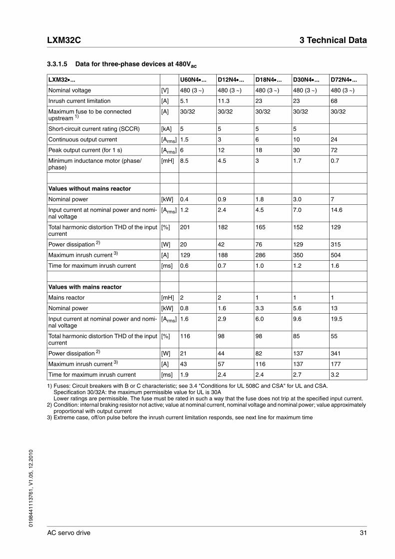
3.3.1.5 Data for three-phase devices at 480Vac
LXM32•... U60N4•... D12N4•... D18N4•... D30N4•... D72N4•...
Nominal voltage [V] 480 (3 ∼) 480 (3 ∼) 480 (3 ∼) 480 (3 ∼) 480 (3 ∼)
Inrush current limitation [A] 5.1 11.3 23 23 68
Maximum fuse to be connected upstream 1)
[A] 30/32 30/32 30/32 30/32 30/32
Short-circuit current rating (SCCR) [kA] 5 5 5 5
Continuous output current [Arms] 1.5 3 6 10 24
Peak output current (for 1 s) [Arms] 6 12 18 30 72
Minimum inductance motor (phase/phase)
[mH] 8.5 4.5 3 1.7 0.7
Values without mains reactor
Nominal power [kW] 0.4 0.9 1.8 3.0 7
Input current at nominal power and nomi-nal voltage
[Arms] 1.2 2.4 4.5 7.0 14.6
Total harmonic distortion THD of the input current
[%] 201 182 165 152 129
Power dissipation 2) [W] 20 42 76 129 315
Maximum inrush current 3) [A] 129 188 286 350 504
Time for maximum inrush current [ms] 0.6 0.7 1.0 1.2 1.6
Values with mains reactor
Mains reactor [mH] 2 2 1 1 1
Nominal power [kW] 0.8 1.6 3.3 5.6 13
Input current at nominal power and nomi-nal voltage
[Arms] 1.6 2.9 6.0 9.6 19.5
Total harmonic distortion THD of the input current
[%] 116 98 98 85 55
Power dissipation 2) [W] 21 44 82 137 341
Maximum inrush current 3) [A] 43 57 116 137 177
Time for maximum inrush current [ms] 1.9 2.4 2.4 2.7 3.2
1) Fuses: Circuit breakers with B or C characteristic; see 3.4 "Conditions for UL 508C and CSA" for UL and CSA.Specification 30/32A: the maximum permissible value for UL is 30ALower ratings are permissible. The fuse must be rated in such a way that the fuse does not trip at the specified input current.
2) Condition: internal braking resistor not active; value at nominal current, nominal voltage and nominal power; value approximately proportional with output current
3) Extreme case, off/on pulse before the inrush current limitation responds, see next line for maximum time

32 AC servo drive
3 Technical Data LXM32C
0198
4411
1376
1, V
1.05
, 12.
2010
3.3.1.6 Peak output currents
Figure 3.3 Peak output current over time (with reference to the continuousoutput current)
Figure 3.4 Peak output current over time (with reference to the continuousoutput current)
1 20105 15 30250
100
200
0
300
t [s]
230V
U45M2
D18M2U30M2
D30M2
D18N4
D72N4D30N4
LXM32 ... LXM32 ...
2 43
I [%]
1 20105 15 30250
100
200
0
300
400
U60N4D12N4
LXM32 ...
I [%]
t [s]2 43
0198
4411
1376
1, V
1.05
, 12.
2010
LXM32C 3 Technical Data
AC servo drive 33
3.3.1.7 DC bus data for single-phase devices
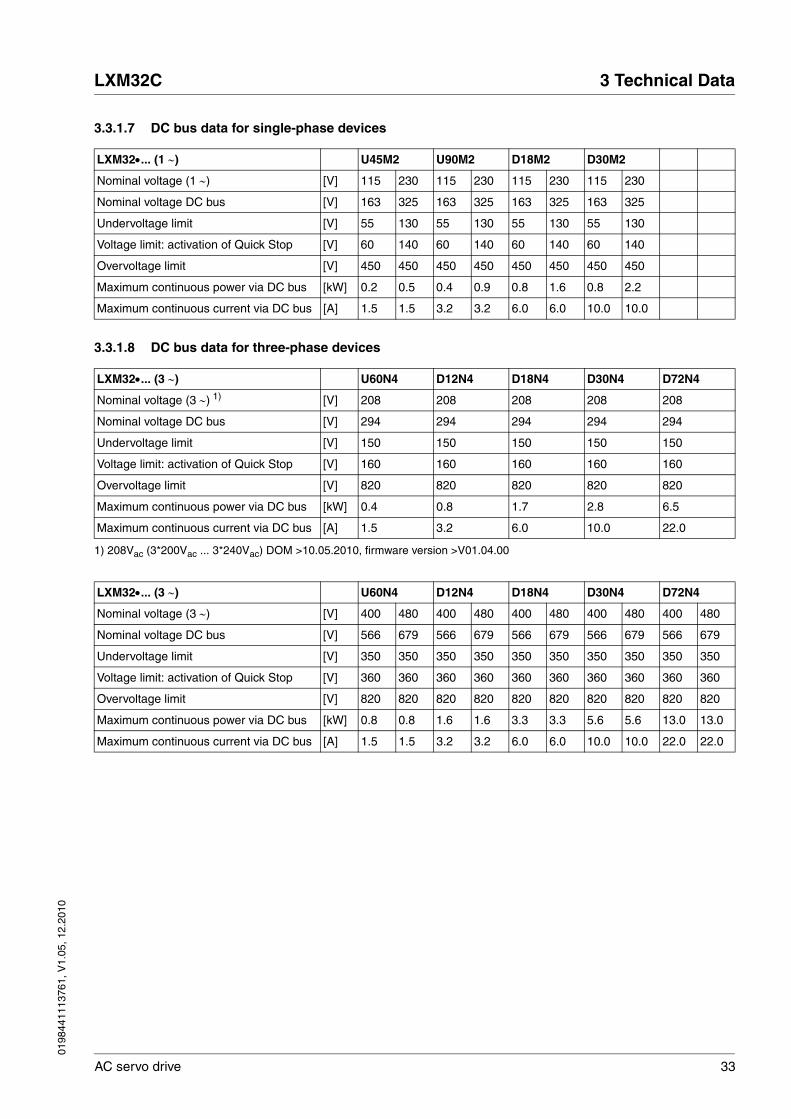
3.3.1.8 DC bus data for three-phase devices
LXM32•... (1 ∼) U45M2 U90M2 D18M2 D30M2
Nominal voltage (1 ∼) [V] 115 230 115 230 115 230 115 230
Nominal voltage DC bus [V] 163 325 163 325 163 325 163 325
Undervoltage limit [V] 55 130 55 130 55 130 55 130
Voltage limit: activation of Quick Stop [V] 60 140 60 140 60 140 60 140
Overvoltage limit [V] 450 450 450 450 450 450 450 450
Maximum continuous power via DC bus [kW] 0.2 0.5 0.4 0.9 0.8 1.6 0.8 2.2
Maximum continuous current via DC bus [A] 1.5 1.5 3.2 3.2 6.0 6.0 10.0 10.0
LXM32•... (3 ∼) U60N4 D12N4 D18N4 D30N4 D72N4
Nominal voltage (3 ∼) 1) [V] 208 208 208 208 208
Nominal voltage DC bus [V] 294 294 294 294 294
Undervoltage limit [V] 150 150 150 150 150
Voltage limit: activation of Quick Stop [V] 160 160 160 160 160
Overvoltage limit [V] 820 820 820 820 820
Maximum continuous power via DC bus [kW] 0.4 0.8 1.7 2.8 6.5
Maximum continuous current via DC bus [A] 1.5 3.2 6.0 10.0 22.0
1) 208Vac (3*200Vac ... 3*240Vac) DOM >10.05.2010, firmware version >V01.04.00
LXM32•... (3 ∼) U60N4 D12N4 D18N4 D30N4 D72N4
Nominal voltage (3 ∼) [V] 400 480 400 480 400 480 400 480 400 480
Nominal voltage DC bus [V] 566 679 566 679 566 679 566 679 566 679
Undervoltage limit [V] 350 350 350 350 350 350 350 350 350 350
Voltage limit: activation of Quick Stop [V] 360 360 360 360 360 360 360 360 360 360
Overvoltage limit [V] 820 820 820 820 820 820 820 820 820 820
Maximum continuous power via DC bus [kW] 0.8 0.8 1.6 1.6 3.3 3.3 5.6 5.6 13.0 13.0
Maximum continuous current via DC bus [A] 1.5 1.5 3.2 3.2 6.0 6.0 10.0 10.0 22.0 22.0
34 AC servo drive
3 Technical Data LXM32C
0198
4411
1376
1, V
1.05
, 12.
2010
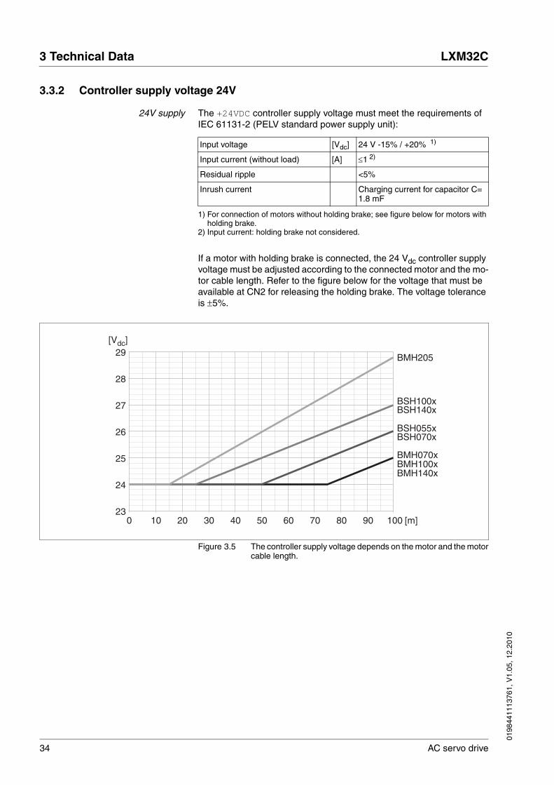
3.3.2 Controller supply voltage 24V
24V supply The +24VDC controller supply voltage must meet the requirements of IEC 61131-2 (PELV standard power supply unit):
If a motor with holding brake is connected, the 24 Vdc controller supply voltage must be adjusted according to the connected motor and the mo-tor cable length. Refer to the figure below for the voltage that must be available at CN2 for releasing the holding brake. The voltage tolerance is ±5%.
Figure 3.5 The controller supply voltage depends on the motor and the motorcable length.
Input voltage [Vdc] 24 V -15% / +20% 1)
1) For connection of motors without holding brake; see figure below for motors with holding brake.
Input current (without load) [A] ≤1 2)
2) Input current: holding brake not considered.
Residual ripple <5%
Inrush current Charging current for capacitor C= 1.8 mF
29
25
24
23
28
27
26
0 908070605040302010 100
BSH055x
BMH205
BSH070x
BSH100xBSH140x
BMH070xBMH100xBMH140x
[m]
[Vdc]

0198
4411
1376
1, V
1.05
, 12.
2010
LXM32C 3 Technical Data
AC servo drive 35
3.3.3 Signals
The digital inputs and outputs of this product can be wired for logic type 1 or logic type 2.
Figure 3.6 Logic type
Signal inputs are protected against reverse polarity, outputs are short-circuit protected. The inputs and outputs are galvanically isolated.
Analog input signals
Digital input signals 24 V When wired as logic type 1, the levels of the opto-isolated inputs DI• comply with IEC 61131-2, type 1.
Capture input signals 24 V When wired as "logic type 1", the levels of the opto-isolated inputs Cap• comply with IEC 61131-2, type 1.
Logic type Active state
(1) Logic type 1 Output supplies current (Source)Current flows to the input
(2) Logic type 2 Output draws current (Sink)Current flows from the input
1 2
+24V
DI0,DI1,...
DI_COM
DQ0,DQ1,...
DQ_COM
DI0,DI1,...
DQ_COM
DQ0,DQ1,...
DI_COM0V
+24V
0V
Voltage range of differential input circuit
[V] -10 ... +10
Input resistance, typical [kΩ] 20
Resolution [Bit] 14
Sampling period [ms] 0.25
Level 0 with logic type 1 (Ulow) [Vdc] -3 ... +5
Level 1 with logic type 1 (Uhigh) [Vdc] +15 ... +30
Input current (typical) [mA] 5
Debounce time 1)
1) Adjustable via parameter (sampling period 250µs)
[ms] 1.5
Level 0 with logic type 1 (Ulow) [Vdc] -3 ... +5
Level 1 with logic type 1 (Uhigh) [Vdc] +15 ... +30
Input current (typical) [mA] 5
Debounce time CAP1 and CAP2 [μs] 2
Jitter CAP1 and CAP2 [μs] <2
36 AC servo drive
3 Technical Data LXM32C
0198
4411
1376
1, V
1.05
, 12.
2010
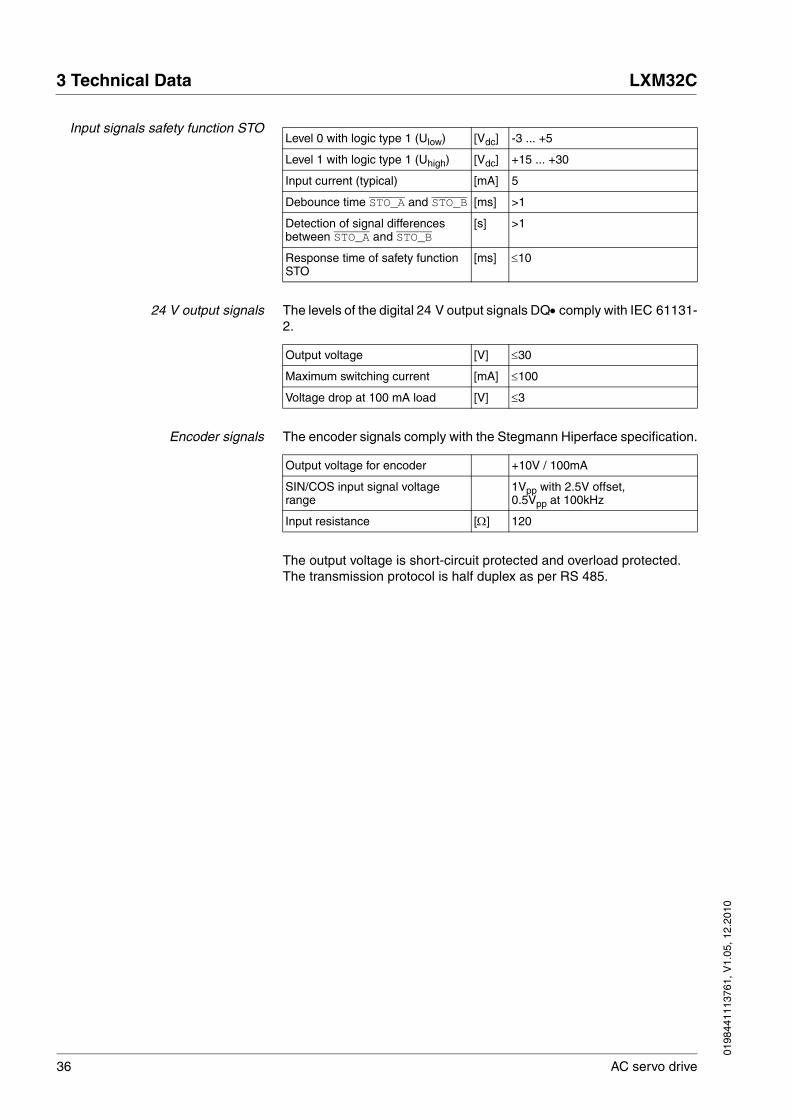
Input signals safety function STO
24 V output signals The levels of the digital 24 V output signals DQ• comply with IEC 61131-2.
Encoder signals The encoder signals comply with the Stegmann Hiperface specification.
The output voltage is short-circuit protected and overload protected. The transmission protocol is half duplex as per RS 485.
Level 0 with logic type 1 (Ulow) [Vdc] -3 ... +5
Level 1 with logic type 1 (Uhigh) [Vdc] +15 ... +30
Input current (typical) [mA] 5
Debounce time STO_A and STO_B [ms] >1
Detection of signal differences between STO_A and STO_B
[s] >1
Response time of safety function STO
[ms] ≤10
Output voltage [V] ≤30
Maximum switching current [mA] ≤100
Voltage drop at 100 mA load [V] ≤3
Output voltage for encoder +10V / 100mA
SIN/COS input signal voltage range
1Vpp with 2.5V offset,0.5Vpp at 100kHz
Input resistance [Ω] 120

0198
4411
1376
1, V
1.05
, 12.
2010
LXM32C 3 Technical Data
AC servo drive 37
3.3.3.1 Output PTO (CN4)
5 V signals are available at the PTO (Pulse Train Out, CN4) output. De-pending on parameter PTO_mode, these signals are ESIM signals (en-coder simulation) or directly transmitted PTI input signals (P/D signals, A/B signals, CW/CCW signals). The PTO output signals can be used as PTI input signals for another device. The PTO output signals have 5 V, even if the PTI input signal is a 24 V signal.
The signal level corresponds to RS422. Due to the input current of the optocoupler in the input circuit, a parallel connection of a driver output to several devices is not permitted.
The basic resolution of the encoder simulation at quadruple resolution is 4096 increments per revolution in the case of rotary motors.
Figure 3.7 Time chart with A, B and index pulse signal, counting forwardsand backwards
Output signal PTO The PTO output signals comply with the RS422 interface specification.
A
I
0
1
0
1
0
1
B
+ -
..7 ... ...8 9 1312 13 9 8..14 1415
Logic level As per RS422 1)
1) Due to the input current of the optocoupler in the input circuit, a parallel connection of a driver output to several devices is not permitted.
Output frequency per signal [kHz] ≤500
Motor increments per second [Inc/s] ≤1.6 * 106

38 AC servo drive
3 Technical Data LXM32C
0198
4411
1376
1, V
1.05
, 12.
2010
3.3.3.2 Input PTI (CN5)
5 V signals or 24 V signals can be connected to the PTI (Pulse Train In) input.
Signals can be connected:
• A/B signals (ENC_A/ENC_B)
• P/D signals (PULSE/DIR)
• CW/CCW signals (CW/CCW)
See also chapter 6.2.11 "Connection PTI (CN5, Pulse Train In)", page 115.
Signal input circuits PTI The way the inputs are wired affects the maximum permissible input fre-quency and the maximum permissible line length:
@ WARNINGUNEXPECTED MOVEMENT
Incorrect or interfered signals as reference values can cause unex-pected movements.
• Use shielded twisted-pair cables.
• If possible, operate the interface with push-pull signals.
• Do not use signals without push-pull in critical applications or in environments subject to interference.
• Do not use signals without push-pull in the case of cable lengths of more than 3 m and limit the frequency to 50 kHz
Failure to follow these instructions can result in death, serious injury or equipment damage.
Input circuit Maximum input frequency Maximum line length
RS422, see Figure 3.8 left 1 MHz 100 m
Push pull, see Figure 3.8 center 0.2 MHz 10 m
Open collector, see Figure 3.8 right 0.01 MHz 1 m

0198
4411
1376
1, V
1.05
, 12.
2010
LXM32C 3 Technical Data
AC servo drive 39
Figure 3.8 Signal input circuits: RS422, Push Pull and Open Collector
A
C
B5VDC
A
C
B
A
C
B
24VDC
24Vdc
5Vdc
RS422 PushPull
PushPull
5VDC
A
C
B
24VDC
A
C
B
OpenCollector
OpenCollector
Input Pin 1) RS422 2) 5V 24V
A Pin 7 Reserved Reserved PULSE(24)ENC_A(24)CW(24)
Pin 8 Reserved Reserved DIR(24)ENC_B(24)CCW(24
B Pin 1 PULSE(5)ENC_A(5)CW(5)
PULSE(5)ENC_A(5)CW(5)
Reserved
Pin4 DIR(5)ENC_B(5)CCW(5)
DIR(5)ENC_B(5)CCW(5)
Reserved
C Pin 2 PULSEENC_ACW
PULSEENC_A CW
PULSEENC_ACW
Pin 5 DIRENC_BCCW
DIRENC_BCCW
DIRENC_BCCW
1) Observe the different pairing in the case of twisted pair:Pin 1 / pin 2 and pin 4 / pin 5 for RS422 and 5V; pin 7 / pin 2 and pin 8 / pin 5 for 24V
2) Due to the input current of the optocoupler in the input circuit, a parallel connection of a driver output to several devices is not permitted.

40 AC servo drive
3 Technical Data LXM32C
0198
4411
1376
1, V
1.05
, 12.
2010
Function A/B signals External A/B signals can be supplied via the PTI input as reference val-ues in operating mode Electronic Gear.
Figure 3.9 Time chart with A/B signal, counting forwards and backwards
Signal Value Function
Signal A before signal B Movement in positive direc-tion
Signal B before signal A Movement in negative direction
Times for pulse/direction Minimum value
Cycle duration A, B 1 μs (1)
Pulse duration 0.4 μs (2)
Lead time (A, B) 200 ns (3)
A0
1
0
1B
+ -
..7 ... ...8 9 1312 13 9 8..14 1415
3
1
2 2
3

0198
4411
1376
1, V
1.05
, 12.
2010
LXM32C 3 Technical Data
AC servo drive 41
Function P/D External P/D signals can be supplied via the PTI input as reference val-ues in the operating mode Electronic Gear.
The motor performs a movement in the case of a rising edge of the PULSE signal. The direction is controlled with the DIR signal.
Figure 3.10 Time chart with pulse/direction signal
Signal Value Function
PULSE 0 -> 1 Motor movement
DIR 0 / open Positive direction
0
1
0
1
+ + +-
PULSE
DIR
322
2
4
1
Times for pulse/direction Minimum value
Cycle duration (pulse) 1 μs (1)
Pulse duration (pulse) 0.4 μs (2)
Lead time (Dir-Pulse) 0 μs (3)
Hold time (Pulse-Dir) 0.4 μs (4)

42 AC servo drive
3 Technical Data LXM32C
0198
4411
1376
1, V
1.05
, 12.
2010
Function CW/CCW External CW/CCW signals can be supplied via the PTI input as refer-ence values in operating mode Electronic Gear.
The motor performs a movement in positive direction the case of a rising edge of the CW signal. The motor performs a movement in negative di-rection the case of a rising edge of the CCW signal.
Figure 3.11 Time chart with "CW/CCW"
Signal Value Function
CW 0 -> 1 Movement in positive direc-tion
CCW 0 -> 1 Movement in negative direction
20
1
0
1
+ + - -
CW
CCW
2
1
2 23
Times for pulse/direction Minimum value
Cycle duration CW, CCW 1 μs (1)
Pulse duration 0.4 μs (2)
Lead time (CW-CCW, CCW-CW)
0 μs (3)

0198
4411
1376
1, V
1.05
, 12.
2010
LXM32C 3 Technical Data
AC servo drive 43
3.3.4 Functional safety
Data for maintenance plan andsafety calculations
Use the following data of the STO safety function for your maintenance plan and the safety calculations:
Lifetime (IEC 61508) Years 20
SFF (IEC 61508)Safe Failure Fraction
[%] 80
HFT (IEC 61508)Hardware Fault ToleranceType A subsystem
1
Safety integrity levelIEC 61508IEC 62061
SIL3SILCL3
PFH (IEC 61508)Probability of Dangerous Hard-ware Failure per Hour
[1/h](FIT)
1*10-9
(1)
PL (ISO 13849-1)Performance Level
e (category 3)
MTTFd (ISO 13849-1)Mean Time to Dangerous Failure
Years 1400
DC (ISO 13849-1)Diagnostic Coverage
[%] 90

44 AC servo drive
3 Technical Data LXM32C
0198
4411
1376
1, V
1.05
, 12.
2010
3.3.5 Braking resistor
The device has an internal braking resistor. If the internal braking resis-tor is insufficient for the dynamics of the application, one or more exter-nal braking resistors must be used.
The resistance values for external braking resistors must not be below the specified minimum resistance. If an external braking resistor is acti-vated by means of the appropriate parameter, the internal braking resis-tor is deactivated.
Further information on the subject Page
Rating the external braking resistor 70
Mounting the external braking resistor (accessory) 89
Electrical installation of the braking resistor (accessory) 70
Setting the braking resistor parameters 168
Order data for external braking resistors (accessory) 389

0198
4411
1376
1, V
1.05
, 12.
2010
LXM32C 3 Technical Data
AC servo drive 45
Table 3.1 Data braking resistor for single-phase devices
LXM32•... U45M2 U90M2 D18M2 D30M2
Resistance value of internal braking resis-tor
[Ω] 94 47 20 10
Continuous power internal braking resis-tor PPR
[W] 10 20 40 60
Peak energy ECR [Ws] 82 166 330 550
External braking resistor minimum [Ω] 68 36 20 12
External braking resistor maximum 1) [Ω] 110 55 27 16
Maximum continuous power external braking resistor
[W] 200 400 600 800
Parameter DCbus_compat = 0 (default value)
Switch-on voltage braking resistor [V] 430 430 430 430
Capacitance [μF] 390 780 1170 1560
Energy absorption of internal capacitors Evar at nominal voltage 115 V +10%
[Ws] 30 60 89 119
Energy absorption of internal capacitors Evar at nominal voltage 200 V +10%
[Ws] 17 34 52 69
Energy absorption of internal capacitors Evar at nominal voltage 230 V +10%
[Ws] 11 22 33 44
Parameter DCbus_compat = 1 (reduced switch-on voltage)
Switch-on voltage braking resistor [V] 395 395 395 395
Capacitance [μF] 390 780 1170 1560
Energy absorption of internal capacitors Evar at nominal voltage 115 V +10%
[Ws] 24 48 73 97
Energy absorption of internal capacitors Evar at nominal voltage 200 V +10%
[Ws] 12 23 35 46
Energy absorption of internal capacitors Evar at nominal voltage 230 V +10%
[Ws] 5 11 16 22
1) The maximum specified braking resistor can derate the peak power of the device. Depending on the application, it is possible to use a higher ohm resistor.

46 AC servo drive
3 Technical Data LXM32C
0198
4411
1376
1, V
1.05
, 12.
2010
See chapter 3.3.1.7 "DC bus data for single-phase devices", page 33 for the DC bus data.
Table 3.2 Data braking resistor for three-phase devices
See chapter 3.3.1.8 "DC bus data for three-phase devices", page 33 for the DC bus data.
LXM32•... U60N4 D12N4 D18N4 D30N4 D72N4
Resistance value of internal braking resis-tor
[Ω] 132 60 30 30 10
Continuous power internal braking resis-tor PPR
[W] 20 40 60 100 150
Peak energy ECR [Ws] 200 400 600 1000 2400
External braking resistor minimum [Ω] 100 47 33 15 8
External braking resistor maximum 1) [Ω] 145 73 50 30 12
Maximum continuous power external braking resistor
[W] 200 500 800 1500 3000
Parameter DCbus_compat 2)
Switch-on voltage [V] 780 780 780 780 780
Capacitance [μF] 110 195 390 560 1120
Energy absorption of internal capacitors Evar at nominal voltage 208 V +10% 3)
[Ws] 28 49 98 141 282
Energy absorption of internal capacitors Evar at nominal voltage 380 V +10%
[Ws] 14 25 50 73 145
Energy absorption of internal capacitors Evar at nominal voltage 400 V +10%
[Ws] 12 22 43 62 124
Energy absorption of internal capacitors Evar at nominal voltage 480 V +10%
[Ws] 3 5 10 14 28
1) The maximum specified braking resistor can derate the peak power of the device. Depending on the application, it is possible to use a higher ohm resistor.
2) Parameter DCbus_compat has no effect in the case of three-phase devices.3) 208Vac (3*200Vac ... 3*240Vac) DOM >10.05.2010, software version >V01.04.00
0198
4411
1376
1, V
1.05
, 12.
2010
LXM32C 3 Technical Data
AC servo drive 47
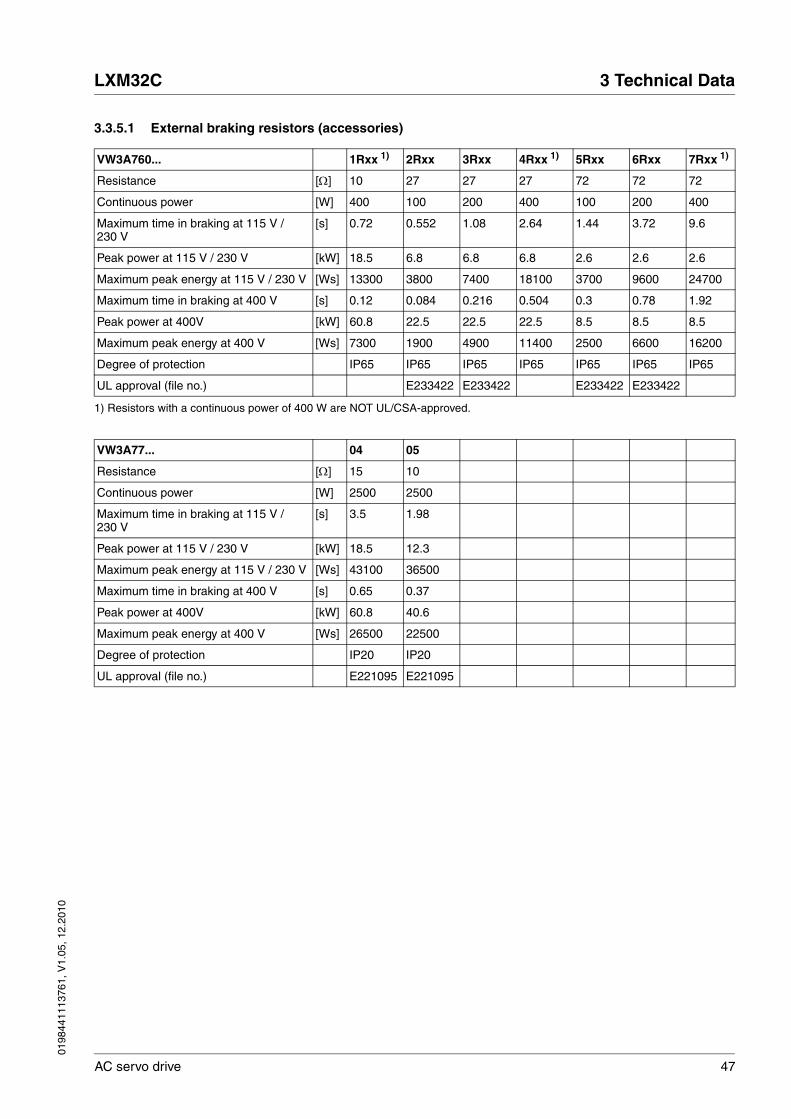
3.3.5.1 External braking resistors (accessories)
VW3A760... 1Rxx 1) 2Rxx 3Rxx 4Rxx 1) 5Rxx 6Rxx 7Rxx 1)
Resistance [Ω] 10 27 27 27 72 72 72
Continuous power [W] 400 100 200 400 100 200 400
Maximum time in braking at 115 V / 230 V
[s] 0.72 0.552 1.08 2.64 1.44 3.72 9.6
Peak power at 115 V / 230 V [kW] 18.5 6.8 6.8 6.8 2.6 2.6 2.6
Maximum peak energy at 115 V / 230 V [Ws] 13300 3800 7400 18100 3700 9600 24700
Maximum time in braking at 400 V [s] 0.12 0.084 0.216 0.504 0.3 0.78 1.92
Peak power at 400V [kW] 60.8 22.5 22.5 22.5 8.5 8.5 8.5
Maximum peak energy at 400 V [Ws] 7300 1900 4900 11400 2500 6600 16200
Degree of protection IP65 IP65 IP65 IP65 IP65 IP65 IP65
UL approval (file no.) E233422 E233422 E233422 E233422
1) Resistors with a continuous power of 400 W are NOT UL/CSA-approved.
VW3A77... 04 05
Resistance [Ω] 15 10
Continuous power [W] 2500 2500
Maximum time in braking at 115 V / 230 V
[s] 3.5 1.98
Peak power at 115 V / 230 V [kW] 18.5 12.3
Maximum peak energy at 115 V / 230 V [Ws] 43100 36500
Maximum time in braking at 400 V [s] 0.65 0.37
Peak power at 400V [kW] 60.8 40.6
Maximum peak energy at 400 V [Ws] 26500 22500
Degree of protection IP20 IP20
UL approval (file no.) E221095 E221095

48 AC servo drive
3 Technical Data LXM32C
0198
4411
1376
1, V
1.05
, 12.
2010
3.3.6 Internal mains filter
Limit values This product meets the EMC requirements according to the standard IEC 61800-3 if the measures described in this manual are implemented during installation.
If the selected composition is not designed for category C1, note the fol-lowing:
Emission The following limit values for interference are complied with if the instal-lation is EMC-compliant and if the cables offered as accessories are used.
External mains filters must be used if longer motor cables are used. See page 49 for the technical data of the external mains filters available as accessories.
Further information on the subject Page
Engineering information external mains filters (accessory) 68
Mounting the external mains filter (accessory) 89
Electrical installation of external mains filters (accessory) 106
Order data external mains filters (accessory) 393
@ WARNINGHIGH-FREQUENCY INTERFERENCE
In a residential environment this product may cause high-frequency interference that require interference suppression.
Failure to follow these instructions can result in death or serious injury.
LXM32• Conducted interference Radiated emission
•••M2 up to a motor cable length of 10 m
Category C2 Category C3
•••M2 motor cable length of 10 m to 20 m
Category C3 Category C3
•••M2 motor cable length of more than 20 m
Not permitted Not permitted
•••N4 up to a motor cable length of 20 m
Category C3 Category C3
•••N4 motor cable length of more than 20 m
Not permitted Not permitted

0198
4411
1376
1, V
1.05
, 12.
2010
LXM32C 3 Technical Data
AC servo drive 49
3.3.7 External mains filters (accessories)
If external mains filters are used, the system integrator and/or machine owner/operator is responsible for complying with the EMC directives.
Emission The specified limit values are complied with if the external mains filters available as accessories are used.
The following limit values for interference are complied with if the instal-lation is EMC-compliant and if the cables offered as accessories are used.
Common external mains filter Several device can be connected to a common external mains filter. Pre-requisites:
• Single-phase devices may only be connected to single-phase mains filters; three-phase devices may only be connected to three-phase devices.
• The total input current of the connected devices must be smaller than or equal to the permissible nominal current of the mains filter.
Further information on the subject Page
Engineering information external mains filters (accessory) 68
Mounting the external mains filter (accessory) 89
Electrical installation of external mains filters (accessory) 106
Order data external mains filters (accessory) 393
LXM32• Conducted interference Radiated emission
•••M2 up to a motor cable length of 20 m
Category C1 Category C3
•••M2 motor cable length of 20 m to 50 m
Category C2 Category C3
•••M2 motor cable length of 50 m to 100 m
Category C3 Category C3
•••M2 motor cable length of more than 100 m
Not permitted Not permitted
•••N4 up to a motor cable length of 20 m
Category C1 Category C3
•••N4 motor cable length of 20 m to 50 m
Category C2 Category C3
•••N4 motor cable length of 50 m to 100 m
Category C3 Category C3
•••N4 motor cable length of more than 100 m
Not permitted Not permitted

50 AC servo drive
3 Technical Data LXM32C
0198
4411
1376
1, V
1.05
, 12.
2010
Assignment of external mains filtersto device type
3.3.8 Mains reactor (accessory)
Mains reactor Mains reactors must be connected upstream if the supply mains does not meet the requirements in terms of mains impedance. High current harmonics result in considerable load on the DC bus capacitors. Mains reactors reduce harmonics in the mains supply. The load on the DC bus capacitors has a decisive impact on the service life of the devices.
A higher continuous power of the device is an additional benefit of using an upstream mains reactor.
Device type 1 ∼ Order number mains filter
LXM32•U45M2 (230 V, 1.5 A, 1 ∼) VW3A4420 (9 A, 1 ∼)
LXM32•U90M2 (230 V, 3 A, 1 ∼) VW3A4420 (9 A, 1 ∼)
LXM32•D18M2 (230 V, 6 A, 1 ∼) VW3A4421 (16 A, 1 ∼)
LXM32•D30M2 (230 V, 10 A, 1 ∼) VW3A4421 (16 A, 1 ∼)
Device type 3 ∼ Order number mains filter
LXM32•U60N4 (480 V, 1.5 A, 3 ∼) VW3A4422 (15 A, 3 ∼)
LXM32•D12N4 (480 V, 3 A, 3 ∼) VW3A4422 (15 A, 3 ∼)
LXM32•D18N4 (480 V, 6 A, 3 ∼) VW3A4422 (15 A, 3 ∼)
LXM32•D30N4 (480 V, 10 A, 3 ∼) VW3A4422 (15 A, 3 ∼)
LXM32•D72N4 (480 V, 24 A, 3 ∼) VW3A4423 (25 A, 3 ∼)
Further information on the subject Page
Engineering information mains reactor (accessory) 67
Mounting the mains reactor (accessory) 89
Electrical installation of the mains reactor (accessory) 106
Order data mains reactor (accessory) 393

0198
4411
1376
1, V
1.05
, 12.
2010
LXM32C 3 Technical Data
AC servo drive 51
3.4 Conditions for UL 508C and CSA
If the product is used to comply with UL 508C or CSA, the following con-ditions must also be met:
Ambient temperature duringoperation
Fuses Use class J fuses as per UL 248-4.
Wiring Use at least 60/75 °C copper conductors.
400/480 V three-phase devices 400/480 V three-phase devices may only be operated via 480Y/277Vac mains.
Overvoltage category In the case of single-phase devices, a Schneider Electric surge protec-tive device TVS230XR40 and in the case of three-phase devices, a Sch-neider Electric surge protective device TVS4XW100C or a UL-listed surge protective device with the following designation must be available in all phases of the mains connection of the drive in the final installation:
UL Category Code VZCAType 1 or 2Operating Voltage 240V for 1-phase systems and 480Y/277V for 3-phase systemsVoltage Protection Rating (VPR) max. 4000VNominal Discharge Current Rating (In) min. 3kA
3.5 Certifications
Product certifications:
Surrounding air temperature [°C] 0 ... +50
Maximum fuse rating of fuse to be connected upstream for LXM32••••M2
[A] 25
Maximum fuse rating of fuse to be connected upstream for LXM32••••N4
[A] 30
Certified by Assigned number
TÜV Nord SAS-192/2008TB-1
UL E153659
CSA 2320425

52 AC servo drive
3 Technical Data LXM32C
0198
4411
1376
1, V
1.05
, 12.
2010
3.6 Declaration of conformity
The following declaration of conformity is applicable if the product is used under the specified conditions and with the cables listed in the Ac-cessories chapter.
SCHNEIDER ELECTRIC MOTION DEUTSCHLAND GmbH Breslauer Str. 7 D-77933 Lahr
EC DECLARATION OF CONFORMITY
YEAR 2010
according to EC Directive on Machinery 2006/42/EC according to EC Directive EMC 2004/108/EC according to EC Directive Low Voltage 2006/95/EC
We hereby declare that the products listed below meet the requirements of the EC Directives indicated with respect to design, construction and version distributed by us. This declaration becomes invalid in the case of any modification to the products not authorized by us.
Designation: AC Servo drive including modules
Type: LXM32Axxxxx, LXM32Cxxxxx, LXM32Mxxxxx, VW3A3607, VW3A3608, VW3A3616, VW3A3618, VW3M3301,VW3M3401, VW3M3402, VW3M3403, VW3M3501
Applied harmonized standards, especially:
EN ISO 13849-1:2008, Performance Level "e" EN 61508:2001, SIL 3 EN 61800-5-1:2007 EN 61800-3:2004, second environment
Applied national standards and technical specifications, especially:
UL 508C CSA C22.2 No. 14-10 Product documentation
Company stamp: Date/Signature: 23 September 2010
Name/Department: Wolfgang Brandstätter/Development

0198
4411
1376
1, V
1.05
, 12.
2010
LXM32C 3 Technical Data
AC servo drive 53
3.7 TÜV certificate for functional safety

54 AC servo drive
3 Technical Data LXM32C
0198
4411
1376
1, V
1.05
, 12.
2010
0198
4411
1376
1, V
1.05
, 12.
2010
LXM32C 4 Basics
AC servo drive 55
44 Basics
4.1 Functional safety
Automation and safety engineering are two areas that were completely separated in the past but recently have become more and more inte-grated. Engineering and installation of complex automation solutions are greatly simplified by integrated safety functions.
Usually, the safety engineering requirements depend on the application. The level of the requirements results from the risk and the hazard po-tential arising from the specific application.
Integrated safety function "SafeTorque Off" STO
The integrated safety function STO (IEC 61800-5-2) allows for a cate-gory 0 stop as per IEC 60204-1 without external power contactors. It is not necessary to interrupt the supply voltage for a category 0 stop. This reduces the system costs and the response times.
IEC 61508 standard The standard IEC 61508 "Functional safety of electrical/electronic/pro-grammable electronic safety-related systems" covers the safety-related function. Instead of a single component, an entire function chain (for ex-ample, from a sensor through the logical processing units to the actua-tor) is considered as a unit. This function chain must meet the requirements of the specific safety integrity level as a whole. Systems and components that can be used in various applications for safety tasks with comparable risk levels can be developed on this basis.
SIL, Safety Integrity Level The standard IEC 61508 defines 4 safety integrity levels (SIL) for safety functions. SIL1 is the lowest level and SIL4 is the highest level. A hazard and risk analysis serves as a basis for determining the required safety integrity level. This is used to decide whether the relevant function chain is to be considered as a safety function and which hazard potential it must cover.
PFH, Probability of a dangeroushardware failure per hour
To maintain the safety function, the IEC 61508 standard requires vari-ous levels of measures for avoiding and controlling faults, depending on the required SIL. All components of a safety function must be subjected to a probability assessment to evaluate the effectiveness of the meas-ures implemented for controlling faults. This assessment determines the PFH (probability of a dangerous failure per hour) for a safety system. This is the probability per hour that a safety system fails in a hazardous manner and the safety function cannot be correctly executed. Depend-ing on the SIL, the PFH must not exceed certain values for the entire safety system. The individual PFH values of a function chain are added. The result must not exceed the maximum value specified in the stand-ard.
SIL PFH at high demand or continuous demand
4 ≥10-9 ... <10-8
3 ≥10-8 ... <10-7
2 ≥10-7 ... <10-6
1 ≥10-6 ... <10-5

56 AC servo drive
4 Basics LXM32C
0198
4411
1376
1, V
1.05
, 12.
2010
HFT and SFF Depending on the SIL for the safety system, the IEC 61508 standard re-quires a specific hardware fault tolerance HFT in connection with a spe-cific proportion of safe failures SFF (safe failure fraction). The hardware fault tolerance is the ability of a system to execute the required safety function in spite of the presence of one or more hardware faults. The SFF of a system is defined as the ratio of the rate of safe failures to the total failure rate of the system. According to IEC 61508, the maximum achievable SIL of a system is partly determined by the hardware fault tol-erance HFT and the safe failure fraction SFF of the system.
IEC 61508 distinguishes two types of subsystems (type A subsystem, type B subsystem). These types are specified on the basis of criteria which the standard defines for the safety-relevant components.
Fault avoidance measures Systematic errors in the specifications, in the hardware and the soft-ware, usage faults and maintenance faults of the safety system must be avoided to the maximum degree possible. To meet these requirements, IEC 61508 specifies a number of measures for fault avoidance that must be implemented depending on the required SIL. These measures for fault avoidance must cover the entire life cycle of the safety system, i.e. from design to decommissioning of the system.
SFF HFT type A subsystem HFT type B subsystem
0 1 2 0 1 2
< 60% SIL1 SIL2 SIL3 --- SIL1 SIL2
60% ... <90% SIL2 SIL3 SIL4 SIL1 SIL2 SIL3
90% ... < 99% SIL3 SIL4 SIL4 SIL2 SIL3 SIL4
≥99% SIL3 SIL4 SIL4 SIL3 SIL4 SIL4

0198
4411
1376
1, V
1.05
, 12.
2010
LXM32C 5 Engineering
AC servo drive 57
55 Engineering
This chapter contains information on the application of the product that is vital in the design phase.
Subject Page
5.1 "Electromagnetic compatibility, EMC" 58
5.2 "Cables" 62
5.3 "Residual current device" 65
5.4 "Operation in an IT mains" 65
5.5 "Parallel connection DC bus" 66
5.6 "Mains reactor" 67
5.7 "Mains filter" 68
5.8 "Rating the braking resistor" 70
5.9 "Safety function STO ("Safe Torque Off")" 77
5.10 "Logic type" 82
5.11 "Monitoring functions" 83
5.12 "Configurable inputs and outputs" 84

58 AC servo drive
5 Engineering LXM32C
0198
4411
1376
1, V
1.05
, 12.
2010
5.1 Electromagnetic compatibility, EMC
Limit values This product meets the EMC requirements according to the standard IEC 61800-3 if the measures described in this manual are implemented during installation.
If the selected composition is not designed for category C1, note the fol-lowing:
An EMC-compliant design is required to meet the specified limit values. Note the following requirements:
Control cabinet design
@ WARNINGSIGNAL AND DEVICE INTERFERENCE
Signal interference can cause unexpected responses of device.
• Install the wiring in accordance with the EMC requirements.
• Verify compliance with the EMC requirements.
Failure to follow these instructions can result in death, serious injury or equipment damage.
@ WARNINGHIGH-FREQUENCY INTERFERENCE
In a residential environment this product may cause high-frequency interference that require interference suppression.
Failure to follow these instructions can result in death or serious injury.
EMC measures Objective
Use galvanised or chrome-plated mounting plates, make large contact surface connections for metal parts, remove paint from contact surfaces
Good conductivity due to two-dimensional con-tacts
Ground the control cabinet, door and mounting plate with ground straps or ground wires with a cross section greater than 10 mm2 (AWG 6).
Reduces emissions.
Fit switching devices such as contactors, relays or solenoid valves with interference suppression units or arc suppressors (for example, diodes, varistors, RC circuits).
Reduces mutual interfer-ence
Install power and control components separately. Reduces mutual interfer-ence

0198
4411
1376
1, V
1.05
, 12.
2010
LXM32C 5 Engineering
AC servo drive 59
Shielded cables
Cable installation
Power supply
EMC measures Objective
Connect large surface areas of cable shields, use cable clamps and ground straps.
Reduces emissions.
Use cable clamps to connect a large surface area of the shields of all shielded cables to the mounting plate at the control cabinet entry.
Reduces emissions.
Ground shields of digital signal wires at both ends by connecting them to a large surface or via con-ductive connector housings.
Reduces interference affecting the signal wires, reduces emis-sions
Ground the shields of analog signal wires directly at the device (signal input); insulate the shield at the other cable end or ground it via a capacitor (for example, 10 nF).
Reduces ground loops due to low-frequency interference.
Use only shielded motor cables with copper braid and a coverage of at least 85%, ground a large sur-face area of the shield at both ends.
Diverts interference cur-rents in a controlled way, reduces emissions.
EMC measures Objective
Do not route fieldbus cables and signal wires in a single cable duct together with lines with DC and AC voltages of more than 60 V. (Fieldbus cables, signal lines and analog lines may be in the same cable duct)
Recommendation: Use separate cable ducts at least 20 cm apart.
Reduces mutual interfer-ence
Keep cables as short as possible. Do not install unnecessary cable loops, use short cables from the central grounding point in the control cabinet to the external ground connection.
Reduces capacitive and inductive interference.
Use equipotential bonding conductors in systems with- wide-area installations- different voltage supplies- networking across several buildings
Reduces current in the cable shield, reduces emissions.
Use equipotential bonding conductors with fine wires
Diverts high-frequency interference currents.
If motor and machine are not conductively con-nected, for example by an insulated flange or a con-nection without surface contact, you must ground the motor with a ground wire > 10 mm2 (AWG 6) or a ground strap.
Reduces emissions, increases immunity.
Use twisted pair for 24 Vdc signals. Reduces interference affecting the signal cables, reduces emis-sions.
EMC measures Objective
Operate product on mains with grounded neutral point.
Enables effectiveness of mains filter.
Surge arrester if there is a risk of overvoltage. Reduces the risk of damage caused by over-voltage.
60 AC servo drive
5 Engineering LXM32C
0198
4411
1376
1, V
1.05
, 12.
2010
Motor and encoder cables Motor and encoder cables are especially critical in terms of EMC. Use only pre-assembled cables (see chapter 12 "Accessories and spare parts") or cables that comply with the specifications (see chapter 5.2 "Cables", page 62) and implement the EMC measures described below.
Additional measures for EMCimprovement
An EMC-compliant design is required to meet the specified limit values. Depending on the application, better results can be achieved with the following measures:
EMC measures Objective
Do not install switching elements in motor cables or encoder cables.
Reduces interference.
Route the motor cable at a distance of at least 20 cm from the signal cable or use shielding plates between the motor cable and signal cable.
Reduces mutual interfer-ence
For long lines, use equipotential bonding conduc-tors.
Reduces current in the cable shield.
Route the motor cable and encoder cable without cutting them. 1)
1) If a cable has to be cut for the installation, it has to be connected with shield con-nections and a metal housing at the point of the cut.
Reduces emission.
EMC measures Objective
Upstream mains reactors Reduces mains harmon-ics, prolongs product service life.
Upstream external mains filters Improves the EMC limit values.
Particularly EMC-compliant design, e.g. in an enclosed control cabinet with 15 dB shielding atten-uation of radiated interference
Improves the EMC limit values.

0198
4411
1376
1, V
1.05
, 12.
2010
LXM32C 5 Engineering
AC servo drive 61
Figure 5.1 EMC measures
L2
L3
L1
M~
Mains filter (optional)Control cabinet
Centralgrounding point
Machine
Motor (groundto machine)
Digital I/O
Motor
Encoder 1

62 AC servo drive
5 Engineering LXM32C
0198
4411
1376
1, V
1.05
, 12.
2010
5.2 Cables
Suitability of the cables Cables must not be twisted, stretched, crushed or bent. Use only cables that comply with the cable specification. Consider the following in deter-mining suitability of the cables:
• Suitable for drag chain applications
• Temperature range
• Chemical resistance
• Outdoor installation
• Underground installation
Shield connections In terms of shield connection, there are the following possibilities:
• Motor cable: The motor cable shield is fastened in the shield clamp at the bottom of the device.
• Shields of the analog cable and the I/O wires to CN6.1 pin 5
• Other cables: The shields are connected to the shield connection at the bottom of the device.
• Alternative: Shield connection via shield clamp and rail, for exam-ple.
Equipotential bonding conductors Potential differences can result in excessive currents on the cable shields. Use equipotential bonding conductors to reduce currents on the cable shields.
The equipotential bonding conductor must be rated for the maximum current flowing. Practical experience has shown that the following con-ductor cross sections can be used:
• 16 mm2 (AWG 4) for equipotential bonding conductors up to a length of 200 m
• 20 mm2 (AWG 4) for equipotential bonding conductors with a length of more than 200 m
Cable guides The device features cable guides at the top and at the bottom. The cable guides do not provide strain relief. The cable guide at the bottom of the device can be used as a shield connection.
NOTE: The upper cable guide is not a shield connection.

0198
4411
1376
1, V
1.05
, 12.
2010
LXM32C 5 Engineering
AC servo drive 63
5.2.1 Overview of the required cables
The properties of the required cables are listed in the table below. Use pre-assembled cables to reduce the risk of wiring errors. Pre-assembled cables can be found in chapter 12 "Accessories and spare parts", page 389. If the product is used to comply with the requirements as per UL 508C, the conditions specified in chapter 3.4 "Conditions for UL 508C and CSA", page 51, must be met.
Table 5.1 Cable specifications
Max. length [m]
Min. cross section [mm2] (AWG)
Shielded, both ends grounded
Twisted pair PELV
Controller supply voltage − 0.75 (AWG 18) Required
STO safety function 1) − 0.75 (AWG 18) 1) Required
Power stage supply voltage − − 2)
Motor phases − 3) − 4) Required
External braking resistor 3 As power stage supply volt-age
Required
Motor encoder 100 6*0.14 mm2 and 2*0.34 mm2 (6*AWG 24 and 2*AWG 20)
Required Required Required
A/B signals 100 0.25 (AWG 22) Required Required Required
PULSE / DIR signals 100 0.14 (AWG 24) Required Required Required
CW/CCW signals 100 0.14 (AWG 24) Required Required Required
ESIM 100 0.14 (AWG 24) Required Required Required
Analog inputs 10 0.14 (AWG 24) Required 5) Required Required
Digital inputs / outputs 30 0.14 (AWG 24) Required
PC, commissioning inter-face
20 0.14 (AWG 24) Required Required Required
1) Note the installation requirements (protected cable installation), see page 78.2) See 6.2.8 "Connection of power stage supply voltage (CN1)"3) Length depends on the required limit values for conducted interference.4) See 6.2.4 "Connecting the motor phases (CN 10, motor)"5) Ground the shield of analog signal wires directly at the device (signal input). Insulate the shield at the other cable end or ground
it via a capacitor (for example, 10 nF) in the case of interference.
64 AC servo drive
5 Engineering LXM32C
0198
4411
1376
1, V
1.05
, 12.
2010
Motor cable and encoder cable
Table 5.2 Data of the motor cable and encoder cable available as accessories
The motor cables and encoder cables are suitable for drag chain appli-cations; they are available in various lengths. See page 389 for the ver-sions available as accessories.
Motor cables Style 20234
Motor cable outside diameter mm VW3M5•01: 12 ± 0.2VW3M5•02: 14 ± 0.3VW3M5•03: 16.3 ± 0.3
Permissible voltage motor cable Vac 600 (UL and CSA)
Encoder cables Style 20233
Encoder cable outside diameter mm VW3M8••2: 6.8 ± 0.2
Temperature range °C -40 ... +90 (fixed)-20 ... +80 (moving)
Permissible bending radius 4 x diameter (fixed)7.5 x diameter (moving)
Cable diameter mm VW3M5•01R•••: 12 ± 0.2VW3M5•02R•••: 14 ± 0.3VW3M5•03R•••: 16,3 ± 0.3
Cable jacket Oil-resistant PUR
Shield Shield braiding
Shield braiding coverage % ≥85
0198
4411
1376
1, V
1.05
, 12.
2010
LXM32C 5 Engineering
AC servo drive 65
5.3 Residual current device
Conditions for use of residualcurrent device
Where the installation regulations require upstream protection against direct or indirect contact by means of a residual current device (RCD) or a residual current monitor (RCM), a residual current device of "type A" can be used for a single-phase drive with connection between N and L. In other cases, a "type B" RCD must be used.
Note the following:
• Filtering of high-frequency currents.
• Delayed triggering to avoid triggering as a result of capacitance which may be present when the unit is switched on. 30 mA residual current devices rarely have a delay. Use a residual current device which is not sensitive to unintentional triggering (for example, resid-ual current devices with increased immunity).
Use residual current devices that meet the following conditions:
• For single-phase devices, type A: Residual current devices of series s.i (super-immunized, Schneider Electric).
• For three-phase devices, type B: sensitive to all current types with approval for frequency inverters.
When using residual current devices, consider the leakage currents of connected consumers.
5.4 Operation in an IT mains
The device is intended for operation in a TT/TN mains. The device is not suitable for operation in an IT mains.
A transformer grounded at the output turns a TT/TN mains into an IT mains. The device may be connected to this mains.
See chapter 3.3.1 "Power stage", page 25 for the approved mains types.
@ WARNINGTHIS PRODUCT MAY CAUSE DIRECT CURRENT IN THE PROTECTIVE GROUND CONDUCTOR
If a residual current device (RCD) is used, conditions must be ob-served.
Failure to follow these instructions can result in death or serious injury.

66 AC servo drive
5 Engineering LXM32C
0198
4411
1376
1, V
1.05
, 12.
2010
5.5 Parallel connection DC bus
Function principle If several devices use the DC bus jointly, this results in energy savings. If on device decelerates, a different device can use the generated brak-ing energy via the DC bus. This energy does not have to be taken from the mains supply and there is no need to waste is by transforming it into heat in the braking resistor.
Several devices can share a common braking resistor. This can reduce the power of the braking resistor and improve the deceleration perform-ance without a braking resistor.
Requirements for use The requirements and limit values for parallel connection of multiple LXM32 via the DC bus can be found on the Internet in the form of Ap-plication Note MNA01M001.
@ WARNINGDESTRUCTION OF SYSTEM COMPONENTS AND LOSS OF CONTROL
Incorrect use of a parallel connection of the DC bus may destroy the drive systems immediately or after a delay.
• Note the requirements concerning the use of a parallel DC bus connection.
Failure to follow these instructions can result in death, serious injury or equipment damage.

0198
4411
1376
1, V
1.05
, 12.
2010
LXM32C 5 Engineering
AC servo drive 67
5.6 Mains reactor
Mains reactor A mains reactor must be used under the following conditions:
• Operation via supply mains with low impedance (short-circuit cur-rent of supply mains greater than specified in chapter 3 "Technical Data", page 25).
• If the nominal power of the drive is insufficient without mains reac-tor.
• In the case of high demands concerning the service life of the drive (for example, 24 h continuous operation).
• In the case of operation with supply mains with reactive current compensation systems.
• For improvement of the power factor at the mains input and for reduction of mains harmonics.
A mains reactor can be used for several devices. Use a mains reactor with a properly rated current.
Low-impedance supply mains cause high current harmonics at the mains input. High current harmonics result in considerable load on the DC bus capacitors. The load on the DC bus capacitors has a decisive impact on the service life of the devices.
Further information on the subject Page
Technical data mains reactor (accessory) 50
Mounting the mains reactor (accessory) 89
Electrical installation of the mains reactor (accessory) 106
Order data mains reactor (accessory) 393
68 AC servo drive
5 Engineering LXM32C
0198
4411
1376
1, V
1.05
, 12.
2010
5.7 Mains filter
Limit values This product meets the EMC requirements according to the standard IEC 61800-3 if the measures described in this manual are implemented during installation.
If the selected composition is not designed for category C1, note the fol-lowing:
See chapter Technical Data, page 48, for the category the device com-plies with.
Better values can be achieved depending on the device and the appli-cation and as well as the design, for example, in the case of installation in an enclosed control cabinet with at least 15db shielding attenuation.
The drives have an integrated mains filter.
An additional external mains filter is required in the case of long motor cables. When using external mains filters, verify compliance with all ap-plicable EMC directives.
If the external mains filters offered in chapter 12.12 "External mains fil-ters" are used, the limit values specified in chapter 3.3.7 "External mains filters (accessories)", page 49, are met.
@ WARNINGHIGH-FREQUENCY INTERFERENCE
In a residential environment this product may cause high-frequency interference that require interference suppression.
Failure to follow these instructions can result in death or serious injury.
Further information on the subject Page
Technical data external mains filters (accessory) 49
Mounting the external mains filter (accessory) 89
Electrical installation of external mains filters (accessory) 106
Order data external mains filters (accessory) 393

0198
4411
1376
1, V
1.05
, 12.
2010
LXM32C 5 Engineering
AC servo drive 69
5.7.1 Deactivating the Y capacitors
The ground connections of the internal Y capacitors can be discon-nected (deactivation). Usually, it is not required to deactivate the ground connection of the Y capacitors.
Figure 5.2 Screw for deactivating/activating the internal Y capacitors
To deactivate the Y capacitors, remove the screw, see Figure 5.2. Keep this screw so you can re-activate the Y capacitors, if required.
NOTE: The EMC limit values specified no longer apply if the Y capaci-tors are deactivated.
1a
1b
70 AC servo drive
5 Engineering LXM32C
0198
4411
1376
1, V
1.05
, 12.
2010
5.8 Rating the braking resistor
@ DANGERFIRE HAZARD CAUSED BY EXTERNAL DRIVING FORCES ACTING ON MOTOR
If external driving forces acting on the motor cause excessively high currents to be regenerated and supplied back to the drive, this may cause overheating and fire of the drive.
• Verify that no energy is supplied to the driving motor after an error of error classes 3 or 4.
Failure to follow these instructions will result in death or serious injury.
@ WARNINGMOTOR WITHOUT BRAKING EFFECT
An insufficient braking resistor causes overvoltage on the DC bus and switches off the power stage. The motor is no longer actively deceler-ated.
• Verify that the braking resistor has a sufficient rating.
• Check the parameter settings for the braking resistor.
• Check the I2t value under the most critical condition by perform-ing a test run. The device switches off at an I2t value of 100%.
• When performing the calculation and the test run, take into account the fact that the DC bus capacitors can absorb less brak-ing energy at higher mains voltages.
Failure to follow these instructions can result in death, serious injury or equipment damage.
@ WARNINGHOT SURFACES
The braking resistor may heat up to over 250°C (480°F) during oper-ation.
• Avoid contact with the hot braking resistor.
• Do not allow flammable or heat-sensitive parts in the immediate vicinity of the braking resistor.
• Provide for good heat dissipation.
• Check the temperature of the braking resistor under the most crit-ical condition by performing a test run.
Failure to follow these instructions can result in death, serious injury or equipment damage.

0198
4411
1376
1, V
1.05
, 12.
2010
LXM32C 5 Engineering
AC servo drive 71
Braking resistors are required for dynamic applications. During deceler-ation, the kinetic energy is transformed into electrical energy in the mo-tor. The electrical energy increases the DC bus voltage. The braking resistor is activated when the defined threshold value is exceeded. The braking resistor transforms electrical energy into heat. If highly dynamic deceleration is required, the braking resistor must be well adapted to the system.
5.8.1 Internal braking resistor
A braking resistor is integrated in the drive to absorb braking energy. The device is shipped with the internal braking resistor active.
Further information on the subject Page
Technical data 3.3.5 "Braking resistor" 44
Mounting the "External braking resistor" (accessory) 89
Electrical installation: 6.2.7 "Braking resistor connection (CN8, Braking Resistor)" (accessory)
103
Setting the braking resistor parameters 168
5.5 "Parallel connection DC bus" 66
Order data for external braking resistors (accessory) 389

72 AC servo drive
5 Engineering LXM32C
0198
4411
1376
1, V
1.05
, 12.
2010
5.8.2 External braking resistor
An external braking resistor is required for applications in which the mo-tor must be decelerated quickly and the internal braking resistor cannot absorb the excess braking energy.
Monitoring The device monitors the power of the braking resistor. The load on the braking resistor can be read out.The connection of the external braking resistor is short-circuit protected. There is no protection in the case of a ground fault.
Selection of the external brakingresistor
The rating of an external braking resistor depends on the required peak power and continuous power with which the braking resistor can be op-erated.
The resistance value R [Ω] is derived from the required peak power and the DC bus voltage.
Figure 5.3 Calculating the resistance R of an external braking resistor
If 2 or more braking resistors are connected to one drive, note the fol-lowing criteria:
• The braking resistors must be connected in parallel or in series so the required resistance is reached. Only connect resistors with identical resistance in parallel in order to evenly distribute the load to all braking resistors.
• The total resistance of all external braking resistors connected to one drive must not fall below a lower limit, see chapter 3.3.5 "Brak-ing resistor".
• The continuous power of the network of connected braking resistors must be calculated. The result must be greater than or equal to the actually required continuous power.
Use only resistors that are specified as braking resistors. For suitable braking resistors, see Accessories, page 392.
Connection of braking resistor A parameter is used to switch between the internal and an external brak-ing resistor. Test the function of the braking resistor under realistic con-ditions during commissioning, see page 150.
Braking resistors with degree of protection IP65 may be installed outside the control cabinet in an appropriate environment.
The external braking resistors listed in the Accessories chapter are shipped with an information sheet that provides details on installation.
For information on the function and the electrical installation, see page 70.
Wire ferrules: If you use wire ferrules, use only wire ferrules with collars for these connection terminals.
R = U2 / Pmax U : Switching threshold [V]
Pmax : Peek power [W]
R: Resistance [Ohm]
0198
4411
1376
1, V
1.05
, 12.
2010
LXM32C 5 Engineering
AC servo drive 73
5.8.3 Rating information
To rate the braking resistor, calculate the proportion contributing to ab-sorbing braking energy.
An external braking resistor is required if the kinetic energy that must be absorbed exceeds the total of the internal proportions, including the in-ternal braking resistor.
Internal energy absorption Braking energy is absorbed internally by the following mechanisms:
• DC bus capacitor Evar
• Internal braking resistor EI
• Electrical losses of the drive Eel
• Mechanical losses of the drive Emech
The energy Evar is the square difference between the voltage before the deceleration process and the response threshold.
The voltage prior to the deceleration process depends on the mains volt-age. The energy absorption by the DC bus capacitors is lowest when the mains voltage is highest. In the calculation, use the values for the high-est mains voltage.
Internal braking resistor Two characteristic values determine the energy absorption of the inter-nal braking resistor.
• The continuous power PPR is the amount of energy that can be con-tinuously absorbed without overloading the braking resistor.
• The maximum energy ECR limits the maximum short-term power that can be absorbed.
If the continuous power was exceeded for a specific time, the braking re-sistor must remain without load for a corresponding period.
The characteristic values PPR and ECR of the internal braking resistor can be found on page 44.
Electrical losses Eel The electrical losses Eel of the drive system can be estimated on the ba-sis of the peak power of the drive. The maximum power dissipation is ap-proximately 10% of the peak power at a typical efficiency of 90%. If the current during deceleration is lower, the power dissipation is reduced ac-cordingly.
Mechanical losses Emech The mechanical losses result from friction during operation of the sys-tem. Mechanical losses are negligible if the time required by the system to coast to a stop without a driving force is considerably longer than the time required to decelerate the system. The mechanical losses can be calculated from the load torque and the velocity from which the motor is to stop.

74 AC servo drive
5 Engineering LXM32C
0198
4411
1376
1, V
1.05
, 12.
2010
Example Deceleration of a rotary motor with the following data:
• Initial speed of rotation: n = 4000 min-1
• Rotor inertia: JR = 4 kgcm2
• Load inertia: JL = 6 kgcm2
Calculation of the energy to be absorbed:
EB = 1/2 * J * (2*π*n * 1/60)2
to 88 Ws
Electrical and mechanical losses are ignored.
In this example, the DC bus capacitors absorb 23 Ws (the value de-pends on the device type, see chapter 3.3.5 "Braking resistor").
The internal braking resistor must absorb the remaining 65 Ws. It can absorb a pulse of 80 Ws. If the load is decelerated once, the internal braking resistor is sufficient.
If the deceleration process is repeated cyclically, the continuous output must be considered. If the cycle time is longer than the ratio of the en-ergy to be absorbed EB and the continuous power PPR, the internal brak-ing resistor is sufficient. If the system decelerates more frequently, the internal braking resistor is not sufficient.
In the example, the ratio EB/PPR is 1.3 s. If the cycle time is shorter, an external braking resistor is required.
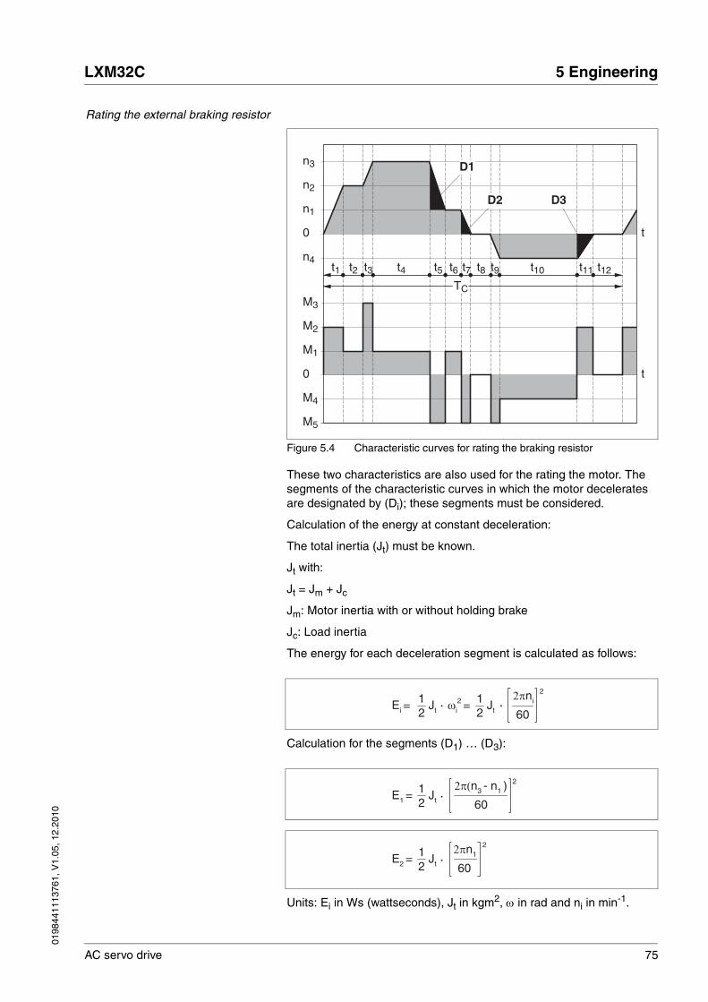
0198
4411
1376
1, V
1.05
, 12.
2010
LXM32C 5 Engineering
AC servo drive 75
Rating the external braking resistor
Figure 5.4 Characteristic curves for rating the braking resistor
These two characteristics are also used for the rating the motor. The segments of the characteristic curves in which the motor decelerates are designated by (Di); these segments must be considered.
Calculation of the energy at constant deceleration:
The total inertia (Jt) must be known.
Jt with:
Jt = Jm + Jc
Jm: Motor inertia with or without holding brake
Jc: Load inertia
The energy for each deceleration segment is calculated as follows:
Calculation for the segments (D1) … (D3):
Units: Ei in Ws (wattseconds), Jt in kgm2, ω in rad and ni in min-1.
n3
n2
n1
0
n4t1 t2 t3 t4 t5 t6 t7 t8 t9 t10 t11 t12
M3
M2
M1
0
t
t
M4
M5
D1
D2 D3
TC
2πni 2
60ωi
2 = Ei = Jt12
Jt12
2π(n3 - n1 ) 2
60 E1 = Jt
12
2πn1 2
60 E2 = Jt
12

76 AC servo drive
5 Engineering LXM32C
0198
4411
1376
1, V
1.05
, 12.
2010
See the technical data for the energy absorption Evar of the devices (without consideration of an internal or external braking resistor).
In the next calculation steps, only consider those segments Di, whose energy Ei exceeds the energy absorption of the device (see chapter 3.3.5 "Braking resistor"). These excess energies EDi must be diverted by means of the braking resistor (internal or external).
EDi is calculated using the following formula:
EDi = Ei - Evar (in Ws)
The continuous power Pc is calculated for each machine cycle:
Units: Pc in [W], EDi in [Ws] and cycle time T in [s]
The selection is made in two steps:
• The maximum energy during deceleration must be less than the peak energy that the braking resistor can absorb: (EDi)<(ECr). In addition, the continuous power of the internal braking resistor must not be exceeded: (PC)<(PPr). If these conditions are met, then the internal braking resistor is sufficient.
• If one of the conditions is not met, you must use an external braking resistor. The braking resistor must be rated in such a way that the conditions are met. The resistance of the braking resistor must be between the specified minimum and maximum values, since other-wise the load can no longer be decelerated or the product might be destroyed.
For order data for the external braking resistors, see chapter Accesso-ries, page 393.
Pc = CycletimeΣEDi

0198
4411
1376
1, V
1.05
, 12.
2010
LXM32C 5 Engineering
AC servo drive 77
5.9 Safety function STO ("Safe Torque Off")
See chapter 55 for information on using the IEC 61508 standard.
5.9.1 Definitions
Safety function STO (IEC 61800-5-2)
The safety function STO ("Safe Torque Off") shuts off the motor torque safely. It is not necessary to interrupt the supply voltage. There is no monitoring for standstill.
Category 0 stop (IEC 60204-1) Stopping by immediate removal of power to the machine actuators (i.e. an uncontrolled stop).
Category 1 stop (IEC 60204-1) Controlled stop with power available to the machine actuators to achieve the stop. Power is not interrupted until the stop is achieved.
5.9.2 Function
The STO safety function integrated into the product can be used to im-plement an "EMERGENCY STOP" (IEC 60204-1) for category 0 stops. With an additional, approved EMERGENCY STOP safety relay module, it is also possible to implement category 1 stops.
Function principle The STO safety function is triggered via 2 redundant inputs. The circuits of the two inputs must be separate so that there are two channels.
The switching process must be simultaneous for both inputs (offset <1s). The power stage is disabled and an error message is generated. The motor can no longer generate torque and coasts down without braking. A restart is possible after resetting the error message with a "Fault Re-set".
The power stage is disabled and an error message is generated if only one of the two inputs is switched off or if the time offset is too great. This error message can only be reset by switching off the product.
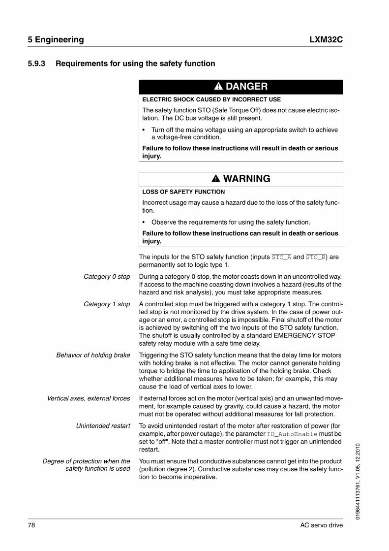
78 AC servo drive
5 Engineering LXM32C
0198
4411
1376
1, V
1.05
, 12.
2010
5.9.3 Requirements for using the safety function
The inputs for the STO safety function (inputs STO_A and STO_B) are permanently set to logic type 1.
Category 0 stop During a category 0 stop, the motor coasts down in an uncontrolled way. If access to the machine coasting down involves a hazard (results of the hazard and risk analysis), you must take appropriate measures.
Category 1 stop A controlled stop must be triggered with a category 1 stop. The control-led stop is not monitored by the drive system. In the case of power out-age or an error, a controlled stop is impossible. Final shutoff of the motor is achieved by switching off the two inputs of the STO safety function. The shutoff is usually controlled by a standard EMERGENCY STOP safety relay module with a safe time delay.
Behavior of holding brake Triggering the STO safety function means that the delay time for motors with holding brake is not effective. The motor cannot generate holding torque to bridge the time to application of the holding brake. Check whether additional measures have to be taken; for example, this may cause the load of vertical axes to lower.
Vertical axes, external forces If external forces act on the motor (vertical axis) and an unwanted move-ment, for example caused by gravity, could cause a hazard, the motor must not be operated without additional measures for fall protection.
Unintended restart To avoid unintended restart of the motor after restoration of power (for example, after power outage), the parameter IO_AutoEnable must be set to "off". Note that a master controller must not trigger an unintended restart.
Degree of protection when thesafety function is used
You must ensure that conductive substances cannot get into the product (pollution degree 2). Conductive substances may cause the safety func-tion to become inoperative.
@ DANGERELECTRIC SHOCK CAUSED BY INCORRECT USE
The safety function STO (Safe Torque Off) does not cause electric iso-lation. The DC bus voltage is still present.
• Turn off the mains voltage using an appropriate switch to achieve a voltage-free condition.
Failure to follow these instructions will result in death or serious injury.
@ WARNINGLOSS OF SAFETY FUNCTION
Incorrect usage may cause a hazard due to the loss of the safety func-tion.
• Observe the requirements for using the safety function.
Failure to follow these instructions can result in death or serious injury.
0198
4411
1376
1, V
1.05
, 12.
2010
LXM32C 5 Engineering
AC servo drive 79
Protected cable installation If short circuits and cross circuits can be expected in connection with safety-related signals and if they are not detected by upstream devices, protected cable installation as per ISO 13849-2 is required.
In the case of an unprotected cable installation, the two signals (both channels) of a safety function may be connected to external voltage if a cable is damaged. If the two channels are connected to external voltage, the safety function is no longer operative.
Data for maintenance plan andsafety calculations
Use the following data of the STO safety function for your maintenance plan and the safety calculations:
Hazard and risk analysis As a system integrator you must conduct a hazard and risk analysis of the entire system. The results must be taken into account in the appli-cation of the safety function.
The type of circuit resulting from the analysis may differ from the follow-ing application examples. Additional safety components may be re-quired. The results of the hazard and risk analysis have priority.
Lifetime (IEC 61508) Years 20
SFF (IEC 61508)Safe Failure Fraction
[%] 80
HFT (IEC 61508)Hardware Fault ToleranceType A subsystem
1
Safety integrity levelIEC 61508IEC 62061
SIL3SILCL3
PFH (IEC 61508)Probability of Dangerous Hard-ware Failure per Hour
[1/h](FIT)
1*10-9
(1)
PL (ISO 13849-1)Performance Level
e (category 3)
MTTFd (ISO 13849-1)Mean Time to Dangerous Failure
Years 1400
DC (ISO 13849-1)Diagnostic Coverage
[%] 90
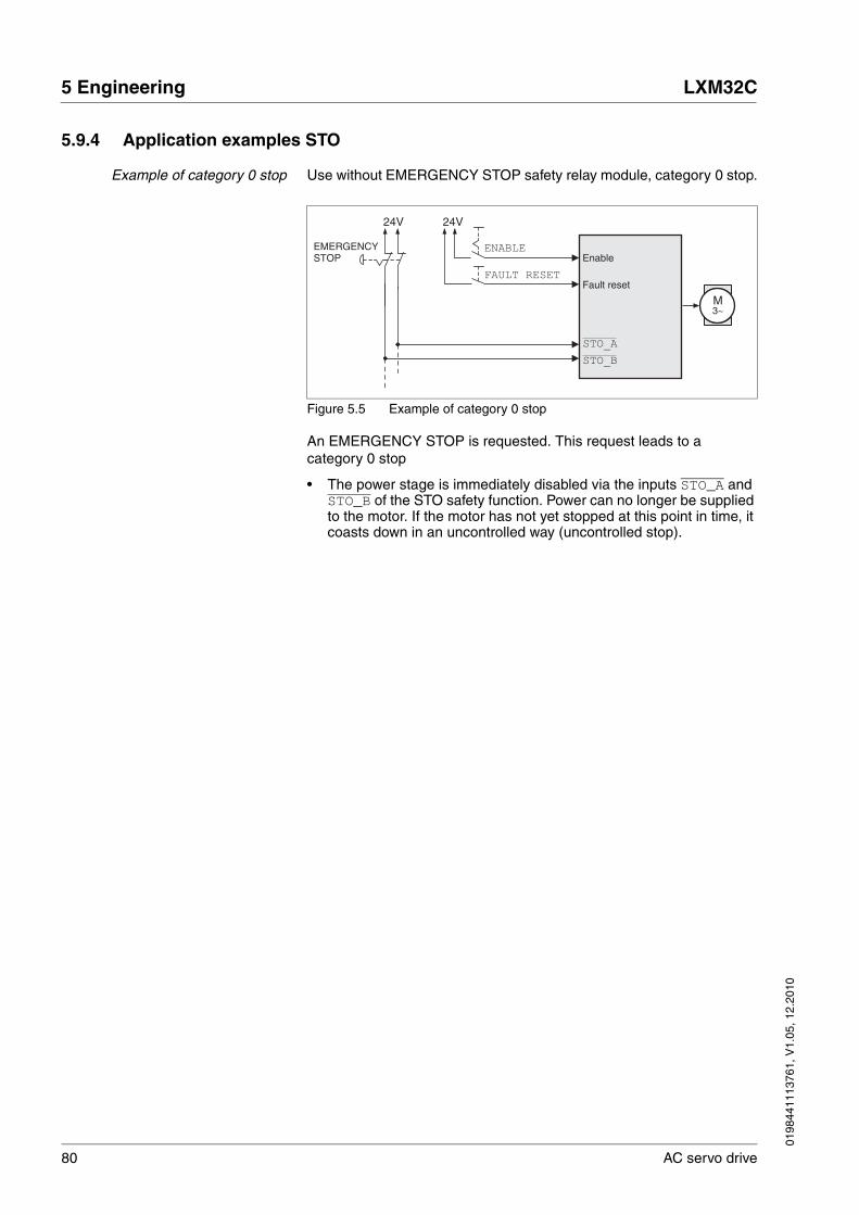
80 AC servo drive
5 Engineering LXM32C
0198
4411
1376
1, V
1.05
, 12.
2010
5.9.4 Application examples STO
Example of category 0 stop Use without EMERGENCY STOP safety relay module, category 0 stop.
Figure 5.5 Example of category 0 stop
An EMERGENCY STOP is requested. This request leads to a category 0 stop
• The power stage is immediately disabled via the inputs STO_A and STO_B of the STO safety function. Power can no longer be supplied to the motor. If the motor has not yet stopped at this point in time, it coasts down in an uncontrolled way (uncontrolled stop).
M3~
24V
ENABLE
FAULT RESET
24V
STO_A
STO_B
Enable
Fault reset
EMERGENCYSTOP
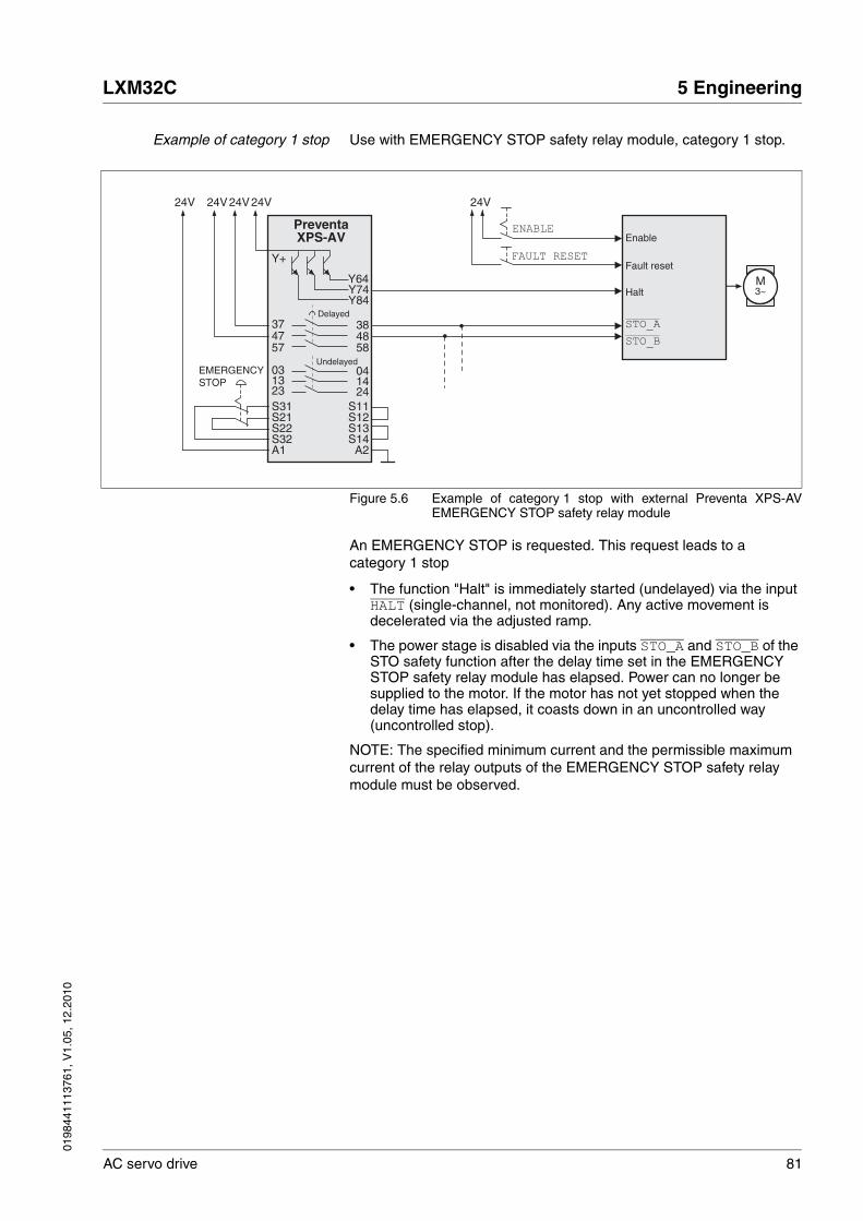
0198
4411
1376
1, V
1.05
, 12.
2010
LXM32C 5 Engineering
AC servo drive 81
Example of category 1 stop Use with EMERGENCY STOP safety relay module, category 1 stop.
Figure 5.6 Example of category 1 stop with external Preventa XPS-AVEMERGENCY STOP safety relay module
An EMERGENCY STOP is requested. This request leads to a category 1 stop
• The function "Halt" is immediately started (undelayed) via the input HALT (single-channel, not monitored). Any active movement is decelerated via the adjusted ramp.
• The power stage is disabled via the inputs STO_A and STO_B of the STO safety function after the delay time set in the EMERGENCY STOP safety relay module has elapsed. Power can no longer be supplied to the motor. If the motor has not yet stopped when the delay time has elapsed, it coasts down in an uncontrolled way (uncontrolled stop).
NOTE: The specified minimum current and the permissible maximum current of the relay outputs of the EMERGENCY STOP safety relay module must be observed.
M3~
Fault reset
Halt
24V 24V
S12
PreventaXPS-AV
Y64
3837
S31
A2A1S14
03 04
Y+
ENABLE
FAULT RESET
Y74Y84
1424
1323
4757 58
48
S11
S13S21S22S32
24V24V24V
STO_A
STO_B
Enable
Delayed
UndelayedEMERGENCYSTOP

82 AC servo drive
5 Engineering LXM32C
0198
4411
1376
1, V
1.05
, 12.
2010
5.10 Logic type
The digital inputs and outputs of this product can be wired for logic type 1 or logic type 2.
Figure 5.7 Logic type
Signal inputs are protected against reverse polarity, outputs are short-circuit protected. The inputs and outputs are galvanically isolated.
The logic type is determined by the way DI_COM and DQ_COM are wired, see Figure 5.7. The logic type affects wiring and control of the sensors; therefore, you should determine the required value in the engineering phase in view of the application.
Special case: Safety function STO The inputs for the STO safety function (inputs STO_A and STO_B) are permanently set to logic type 1.
@ WARNINGUNINTENDED OPERATION
If logic type 2 is used, a ground fault of a signal is detected as an On state.
• Use great care in wiring to exclude the possibility of ground faults.
Failure to follow these instructions can result in death, serious injury or equipment damage.
Logic type Active state
(1) Logic type 1 Output supplies current (Source)Current flows to the input
(2) Logic type 2 Output draws current (Sink)Current flows from the input
1 2
+24V
DI0,DI1,...
DI_COM
DQ0,DQ1,...
DQ_COM
DI0,DI1,...
DQ_COM
DQ0,DQ1,...
DI_COM0V
+24V
0V

0198
4411
1376
1, V
1.05
, 12.
2010
LXM32C 5 Engineering
AC servo drive 83
5.11 Monitoring functions
The monitoring functions in the product can help to guard the system and reduce the risks involved in a system misoperation. These monitor-ing functions may not be used to protect persons.
The following monitoring functions are available:
For a description of the monitoring functions, see chapter 8.8 "Functions for monitoring internal device signals".
Monitoring Task
Data connection Error response if the link becomes inoperative
Limit switch signals Monitors for permissible movement range
Position deviation Monitors for difference between actual position and reference position
Motor overload Monitors for excessively high current in the motor phases
Overvoltage and undervoltage Monitors for overvoltage and undervoltage of the power stage supply and the DC bus
Overtemperature Monitors the device for overtemperature
I2t limitation Power limitation in the case of overloads for the motor, the output current, the output power and the braking resistor.
Commutation Plausibility check of motor acceleration and effective torque
Mains phases Monitoring for missing mains phases
Short circuit / ground fault Monitors for short circuit between motor phase and motor phase and between motor phase and ground
84 AC servo drive
5 Engineering LXM32C
0198
4411
1376
1, V
1.05
, 12.
2010
5.12 Configurable inputs and outputs
This product has digital inputs and outputs that can be configured. The inputs and outputs have a defined standard assignment depending on the operating mode. This assignment can be adapted to the require-ments of the customer's installation. See chapter 8.5.2 "Setting the dig-ital signal inputs and signal outputs" for additional information.
@ WARNINGLOSS OF CONTROL
The use of limit switches can provide some protection against hazards (for example, collision with mechanical stop caused by incorrect ref-erence values).
• If possible, use the limit switches.
• Verify correct connection of the limit switches.
• Verify the correct installation of the limit switches. The limit switches must be mounted in a position far enough away from the mechanical stop to allow for an adequate stopping distance.
• You must release the limit switches before you can use them.
• Verify the correct function of the limit switches.
Failure to follow these instructions can result in death, serious injury or equipment damage.

0198
4411
1376
1, V
1.05
, 12.
2010
LXM32C 6 Installation
AC servo drive 85
66 Installation
An engineering phase is mandatory prior to mechanical and electrical installation. See chapter 5 "Engineering", page 57, for basic information.
@ WARNINGLOSS OF CONTROL
• The designer of any control scheme must consider the potential failure modes of control paths and, for certain critical functions, provide a means to achieve a safe state during and after a path failure. Examples of critical control functions are emergency stop, overtravel stop, power outage and restart.
• Separate or redundant control paths must be provided for critical functions.
• System control paths may include communication links. Consid-eration must be given to the implication of unanticipated transmis-sion delays or failures of the link.
• Observe all accident prevention regulations and local safety guidelines. 1)
• Each implementation of the product must be individually and thor-oughly tested for proper operation before being placed into serv-ice.
Failure to follow these instructions can result in death or serious injury.
1) For USA: Additional information, refer to NEMA ICS 1.1 (latest edition), “Safety Guidelines for the Application, Installation, and Maintenance of Solid State Con-trol” and to NEMA ICS 7.1 (latest edition), “Safety Standards for Construction and Guide for Selection, Installation and Operation of Adjustable-Speed Drive Sys-tems”.

86 AC servo drive
6 Installation LXM32C
0198
4411
1376
1, V
1.05
, 12.
2010
6.1 Mechanical installation
@ DANGERELECTRIC SHOCK CAUSED BY FOREIGN OBJECTS OR DAMAGE
Conductive foreign objects in the product or damage may cause par-asitic voltage.
• Do not use damaged products.
• Keep foreign objects such as chips, screws or wire clippings from getting into the product.
Failure to follow these instructions will result in death or serious injury.
@ WARNINGLOSS OF SAFETY FUNCTION CAUSED BY FOREIGN OBJECTS
Conductive foreign objects, dust or liquids may cause safety functions to become inoperative.
• Do not use the a safety function unless you have protected the system against contamination by conductive substances.
Failure to follow these instructions can result in death or serious injury.
@ WARNINGHOT SURFACES
The heat sink at the product may heat up to over 100°C (212°F) during operation.
• Avoid contact with the hot heat sink.
• Do not allow flammable or heat-sensitive parts in the immediate vicinity.
• Consider the measures for heat dissipation described.
Failure to follow these instructions can result in death or serious injury.

0198
4411
1376
1, V
1.05
, 12.
2010
LXM32C 6 Installation
AC servo drive 87
6.1.1 Mounting the device
Attaching a label with safetyinstructions
� Select the label suitable for the target country.Observe the safety regulations in the target country.
� Attach the label to the front of the device so that it is clearly visible.
Control cabinet The control cabinet must have a sufficient size so that all devices and components can be permanently installed and wired in compliance with the EMC requirements.
The ventilation of the control cabinet must be sufficient to remove the heat generated by all devices and components operated in the control cabinet.
Mounting distances, ventilation When selecting the position of the device in the control cabinet, note the following:
• Mount the device in a vertical position (±10°). This is required for cooling the device.
• Adhere to the minimum installation distances for required cooling. Avoid heat accumulations.
• Do not mount the device close to heat sources.
• Do not mount the device on flammable materials.
• The heated airflow from other devices and components must not heat up the air used for cooling the device.
• If the thermal limits are exceeded during operation, the drive switches off (overtemperature).
• Comply with the specifications in chapter 6.1.2 "Mounting mains fil-ter, mains reactor and braking resistor", page 89, for mounting addi-tional components (external mains filters, mains reactor, external braking resistor).
The connection cables of the devices are routed to the top and to the bottom. The minimum distances must be adhered to for air circulation and cable installation.

88 AC servo drive
6 Installation LXM32C
0198
4411
1376
1, V
1.05
, 12.
2010
Figure 6.1 Mounting distances and air circulation
Mounting the device See chapter 3.2.1 "Dimensional drawings", page 23 for the dimensions of the mounting holes.
NOTE: Painted surfaces have an insulating effect. Before mounting the device to a painted mounting plate, remove all paint across a large area of the mounting points until the metal is completely bare.
� Note the ambient conditions in chapter 3 "Technical Data", page 21.
� Mount the device in a vertical position (±10°).
dd d
c
a
b
d
Distance
a ≥ 100 mm(a ≥ 40 in.)
Free space above the device
b ≥ 100 mm(b ≥ 40 in.)
Free space below the device
c ≥ 60 mm(c ≥ 23.5 in.)
Free space in front of the device
d ≥0 mm(d ≥0 in.)
Space between devices for ambient tem-perature during operation: 0 °C ... +50 °C(32 °F ... 122 °F)
0198
4411
1376
1, V
1.05
, 12.
2010
LXM32C 6 Installation
AC servo drive 89
6.1.2 Mounting mains filter, mains reactor and braking resistor
External mains filter The drives have an integrated mains filter.
An additional external mains filter is required in the case of long motor cables. When using external mains filters, verify compliance with all ap-plicable EMC directives.
� Mount the external mains filter above the device.
Mains reactor A mains reactor must be used under specific conditions as outlined in chapter 5.6 "Mains reactor", page 67. The mains reactor is shipped with an information sheet that provides details on mounting. Information on the electrical installation can be found in chapter 6.2.8 "Connection of power stage supply voltage (CN1)", page 106.
If you install a mains reactor, the power provided by the device is in-creased, see chapter 3.3.1 "Power stage", page 25. Increased power is only available if the corresponding parameter is set during commission-ing.
Further information on the subject Page
Technical data external mains filters (accessory) 49
Engineering information external mains filters (accessory) 68
Electrical installation of external mains filters (accessory) 106
Order data external mains filters (accessory) 393
Further information on the subject Page
Technical data mains reactor (accessory) 50
Engineering information mains reactor (accessory) 67
Electrical installation of the mains reactor (accessory) 106
Order data mains reactor (accessory) 393

90 AC servo drive
6 Installation LXM32C
0198
4411
1376
1, V
1.05
, 12.
2010
External braking resistor
Braking resistors with degree of protection IP65 may be installed outside the control cabinet in an appropriate environment.
The external braking resistors listed in the Accessories chapter are shipped with an information sheet that provides details on installation.
@ WARNINGHOT SURFACES
The braking resistor may heat up to over 250°C (480°F) during oper-ation.
• Avoid contact with the hot braking resistor.
• Do not allow flammable or heat-sensitive parts in the immediate vicinity of the braking resistor.
• Provide for good heat dissipation.
• Check the temperature of the braking resistor under the most crit-ical condition by performing a test run.
Failure to follow these instructions can result in death, serious injury or equipment damage.
Further information on the subject Page
Technical data braking resistor 44
Mounting the external braking resistor (accessory) 89
Electrical installation of the braking resistor (accessory) 103
Setting the braking resistor parameters 168
Order data for external braking resistors (accessory) 389

0198
4411
1376
1, V
1.05
, 12.
2010
LXM32C 6 Installation
AC servo drive 91
6.2 Electrical installation
See chapter 5.3 "Residual current device", page 65 for conditions for us-ing a residual current device.
Logic types The product supports logic type 1 and logic type 2 for digital signals. Note that most of the wiring examples show the logic type 1. The STO safety function must be wired using the logic type 1.
@ DANGERELECTRIC SHOCK CAUSED BY FOREIGN OBJECTS OR DAMAGE
Conductive foreign objects in the product or damage may cause par-asitic voltage.
• Do not use damaged products.
• Keep foreign objects such as chips, screws or wire clippings from getting into the product.
Failure to follow these instructions will result in death or serious injury.
@ DANGERELECTRIC SHOCK CAUSED BY INSUFFICIENT GROUNDING
Insufficient grounding causes the hazard of electric shocks.
• Ground the drive system before applying voltage.
• Do not use conduits as protective ground conductors; use a pro-tective ground conductor inside the conduit.
• The cross section of the protective ground conductor must com-ply with the applicable standards.
• Ground the cable shields at both ends; however, the shields are not protective ground conductors.
Failure to follow these instructions will result in death or serious injury.
@ WARNINGTHIS PRODUCT MAY CAUSE DIRECT CURRENT IN THE PROTECTIVE GROUND CONDUCTOR
If a residual current device (RCD) is used, conditions must be ob-served.
Failure to follow these instructions can result in death or serious injury.

92 AC servo drive
6 Installation LXM32C
0198
4411
1376
1, V
1.05
, 12.
2010
6.2.1 Overview of procedure
� Take into account the information provided in chapter 5 "Engineer-ing". The selected settings affect the entire installation.
� The entire installation procedure must be performed without voltage present.
Sequence of installation steps:
Table 6.1 Installation overview
Finally, verify proper installation.
Connection Connection to Page
Ground connection Grounding screw 94
Motor phases CN10 95
Holding brake CN11 101
DC bus connection CN9 102
External braking resistor CN8 103
Power stage supply CN1 106
Motor encoder (encoder 1) CN3 111
PTO: Encoder simulation ESIM CN4 113
PTI: Pulse/Direction P/D CN5 115
PTI: A/B signals CN5 115
PTI: CW/CCW CN5 115
Safety function STO CN2 118
24V controller supply voltage CN2 118
Analog inputs CN6 121
Digital inputs / outputs CN6 123
Commissioning interface (PC) CN7 125
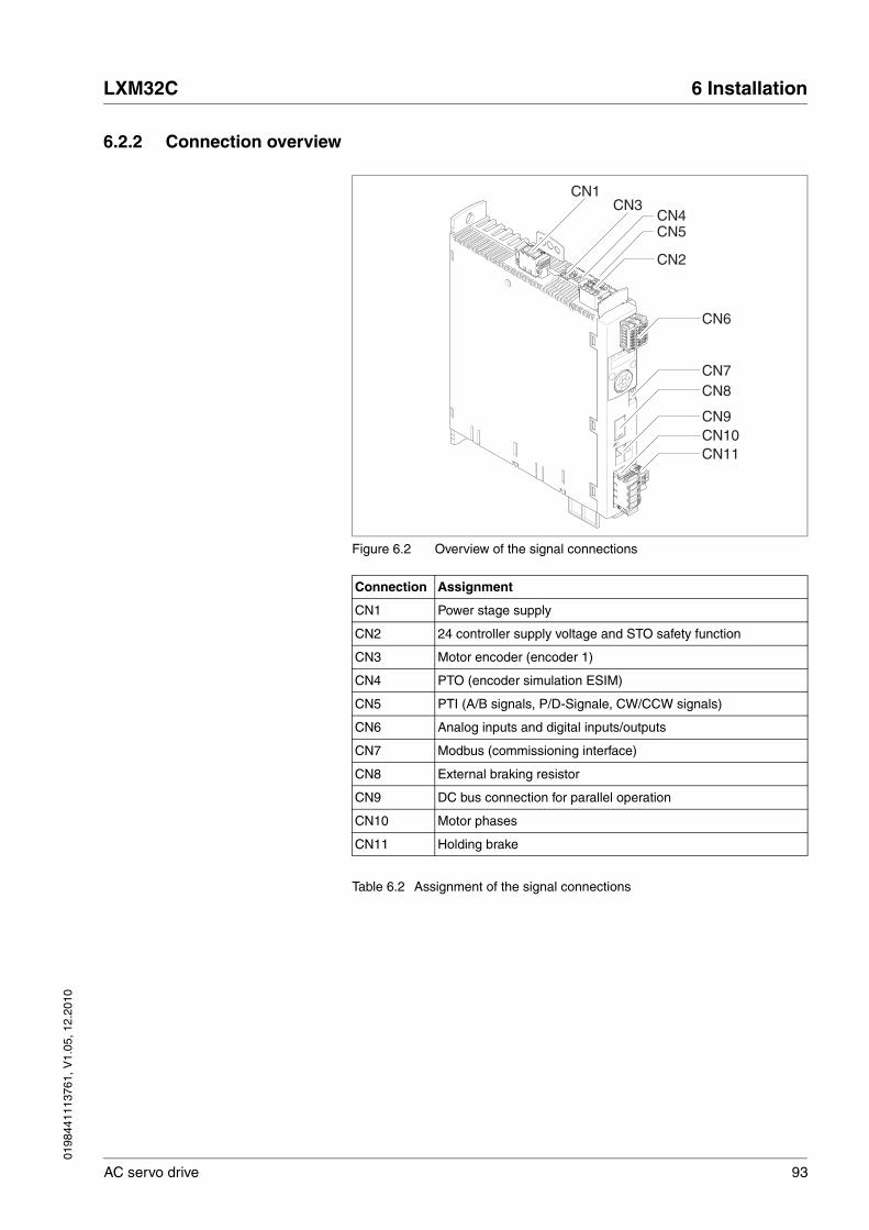
0198
4411
1376
1, V
1.05
, 12.
2010
LXM32C 6 Installation
AC servo drive 93
6.2.2 Connection overview
Figure 6.2 Overview of the signal connections
Table 6.2 Assignment of the signal connections
Connection Assignment
CN1 Power stage supply
CN2 24 controller supply voltage and STO safety function
CN3 Motor encoder (encoder 1)
CN4 PTO (encoder simulation ESIM)
CN5 PTI (A/B signals, P/D-Signale, CW/CCW signals)
CN6 Analog inputs and digital inputs/outputs
CN7 Modbus (commissioning interface)
CN8 External braking resistor
CN9 DC bus connection for parallel operation
CN10 Motor phases
CN11 Holding brake
CN1
CN7
CN6
CN2
CN5
CN11CN10CN9
CN8
CN3CN4

94 AC servo drive
6 Installation LXM32C
0198
4411
1376
1, V
1.05
, 12.
2010
6.2.3 Connection grounding screw
The central grounding screw of the product is located at the bottom of the front side.
� Connect the ground connection of the device to the central ground point of the system.
@ DANGERELECTRIC SHOCK CAUSED BY INSUFFICIENT GROUNDING
This drive system has an increased leakage current > 3.5 mA.
• Use a protective ground conductor at with least 10 mm2 (AWG 6) or two protective ground conductors with the cross section of the conductors supplying the power terminals. Verify compliance with all local and national electrical code requirements as well as all other applicable regulations with respect to grounding of all equipment.
Failure to follow these instructions will result in death or serious injury.
LXM32•...
Tightening torque for terminal screws [Nm] ([lb.in]) 5.5 (48.7)
0198
4411
1376
1, V
1.05
, 12.
2010
LXM32C 6 Installation
AC servo drive 95
6.2.4 Connecting the motor phases (CN 10, motor)
Route the cables from the motor and the encoder to the device (start at the motor). Due to the pre-assembled connectors, this direction is often faster and easier.
@ DANGERELECTRIC SHOCK
High voltages at the motor connection may occur unexpectedly.
• The motor generates voltage when the shaft is rotated. Prior to performing any type of work on the drive system, block the motor shaft to prevent rotation.
• AC voltage can couple voltage to unused conductors in the motor cable. Insulate both ends of unused conductors in the motor cable.
• The system integrator is responsible for compliance with all local and national electrical code requirements as well as all other applicable regulations with respect to grounding of all equipment. Supplement the motor cable grounding conductor with an addi-tional protective ground conductor to the motor housing.
Failure to follow these instructions will result in death or serious injury.
@ WARNINGUNEXPECTED MOVEMENT
Drive systems may perform unexpected movements because of in-correct connection or other errors.
• Operate the device with approved motors only. Even if motors are similar, different adjustment of the encoder system may be a source of hazards.
• Even if the connectors for power connection and encoder match mechanically, this does NOT imply that they may be used.
Failure to follow these instructions can result in death, serious injury or equipment damage.

96 AC servo drive
6 Installation LXM32C
0198
4411
1376
1, V
1.05
, 12.
2010
Cable specifications See chapter 5.2 "Cables", page 62 for information on the cables.
Note the following information:
• You may only connect the original motor cable (with two wires for the holding brake).
• The wires for the holding brake must also be connected to the device at connection CN11 in the case of motors without holding brakes. At the motor end, connect the wires to the appropriate pins for the holding brake; the cable can then be used for motors with or without holding brake. If you do not connect the wires at the motor end, you must isolate each wire individually (inductive voltages).
• Observe the polarity of the holding brake voltage.
• The voltage for the holding brake depends on the controller supply voltage (PELV). Observe the tolerance for the controller voltage and the specified voltage for the holding brake.
� Use pre-assembled cables (page 393) to reduce the risk of wiring errors.
Shield: Required, both ends grounded
Twisted Pair: -
PELV: The wires for the holding brake must be PELV-compliant.
Cable composition: 3 wires for motor phases2 wires for holding brakeCross section: The conductors must have a sufficiently large cross section so that the fuse at the mains connec-tion can trip if required.
Maximum cable length: Depends on the required limit values for conducted interference, see chap-ter 3.3.6 "Internal mains filter", page 48, and chapter 3.3.7 "External mains filters (accessories)", page 49.
Special features: Contains wires for the holding brake
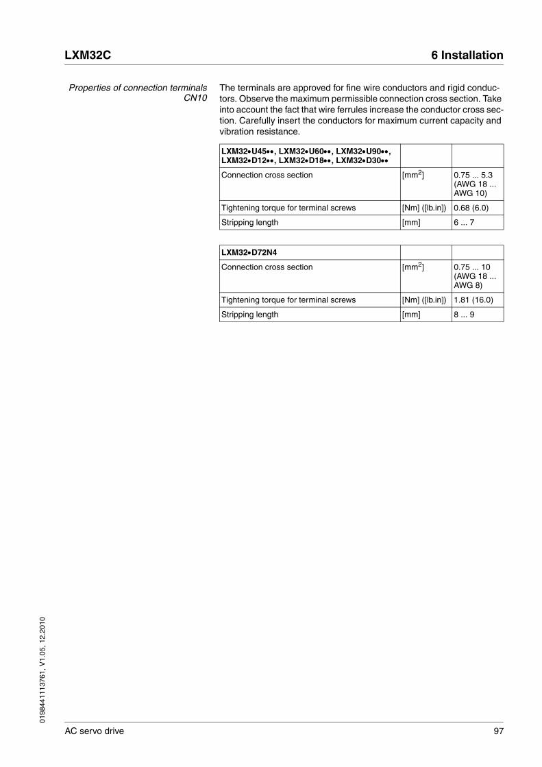
0198
4411
1376
1, V
1.05
, 12.
2010
LXM32C 6 Installation
AC servo drive 97
Properties of connection terminalsCN10
The terminals are approved for fine wire conductors and rigid conduc-tors. Observe the maximum permissible connection cross section. Take into account the fact that wire ferrules increase the conductor cross sec-tion. Carefully insert the conductors for maximum current capacity and vibration resistance.
LXM32•U45••, LXM32•U60••, LXM32•U90••, LXM32•D12••, LXM32•D18••, LXM32•D30••
Connection cross section [mm2] 0.75 ... 5.3 (AWG 18 ... AWG 10)
Tightening torque for terminal screws [Nm] ([lb.in]) 0.68 (6.0)
Stripping length [mm] 6 ... 7
LXM32•D72N4
Connection cross section [mm2] 0.75 ... 10 (AWG 18 ... AWG 8)
Tightening torque for terminal screws [Nm] ([lb.in]) 1.81 (16.0)
Stripping length [mm] 8 ... 9
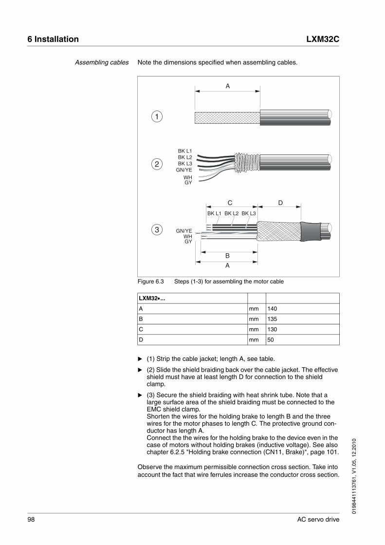
98 AC servo drive
6 Installation LXM32C
0198
4411
1376
1, V
1.05
, 12.
2010
Assembling cables Note the dimensions specified when assembling cables.
Figure 6.3 Steps (1-3) for assembling the motor cable
� (1) Strip the cable jacket; length A, see table.
� (2) Slide the shield braiding back over the cable jacket. The effective shield must have at least length D for connection to the shield clamp.
� (3) Secure the shield braiding with heat shrink tube. Note that a large surface area of the shield braiding must be connected to the EMC shield clamp.Shorten the wires for the holding brake to length B and the three wires for the motor phases to length C. The protective ground con-ductor has length A.Connect the the wires for the holding brake to the device even in the case of motors without holding brakes (inductive voltage). See also chapter 6.2.5 "Holding brake connection (CN11, Brake)", page 101.
Observe the maximum permissible connection cross section. Take into account the fact that wire ferrules increase the conductor cross section.
BK L1 BK L2 BK L3
GN/YE
C
A
B
WHGY
D
BK L1BK L2BK L3
GN/YE
WHGY
A
3
1
2
LXM32•...
A mm 140
B mm 135
C mm 130
D mm 50

0198
4411
1376
1, V
1.05
, 12.
2010
LXM32C 6 Installation
AC servo drive 99
Monitoring The device monitor the motor phases for:
• Short circuit between the motor phases
• Short circuit between the motor phases and ground
Short circuits between the motor phases and the DC bus, the braking re-sistor or the holding brake wires are not detected.
Wiring diagram motor
Figure 6.4 Wiring diagram motor with holding brake
M3~
BR+
BR-
W
U
V
CN
10 M
otor
WV
U
CN
11B
rake
-+
Connection Meaning Color
U Motor phase Black L1 (BK)
V Motor phase Black L2 (BK)
W Motor phase Black L3 (BK)
PE Protective ground conductor Green/yellow (GN/YE)
BR+ Holding brake + White (WH) or black 5 (BK)
BR- Holding brake - Gray (GR) or black 6 (BK)
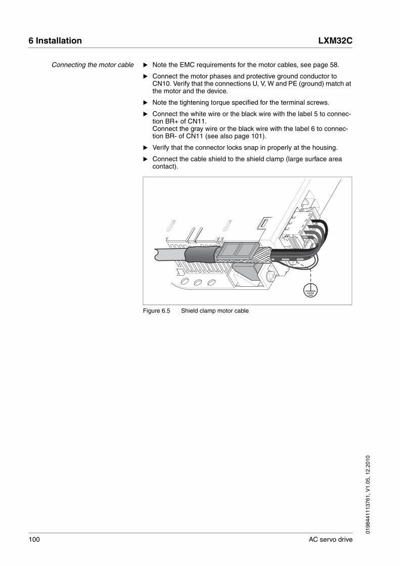
100 AC servo drive
6 Installation LXM32C
0198
4411
1376
1, V
1.05
, 12.
2010
Connecting the motor cable � Note the EMC requirements for the motor cables, see page 58.
� Connect the motor phases and protective ground conductor to CN10. Verify that the connections U, V, W and PE (ground) match at the motor and the device.
� Note the tightening torque specified for the terminal screws.
� Connect the white wire or the black wire with the label 5 to connec-tion BR+ of CN11.Connect the gray wire or the black wire with the label 6 to connec-tion BR- of CN11 (see also page 101).
� Verify that the connector locks snap in properly at the housing.
� Connect the cable shield to the shield clamp (large surface area contact).
Figure 6.5 Shield clamp motor cable

0198
4411
1376
1, V
1.05
, 12.
2010
LXM32C 6 Installation
AC servo drive 101
6.2.5 Holding brake connection (CN11, Brake)
The optional holding brake of a motor is connected to connection CN11. The integrated holding brake controller releases the holding brake when the power stage is enabled. When the power stage is disabled, the hold-ing brake is re-applied.
The wires must have a sufficiently large cross section so that the fuse at the mains connection can trip if required.
Note the following information:
• You may only connect the original motor cable (with two wires for the holding brake).
• The wires for the holding brake must be connected to the device via connection CN11 even in the case of motors without holding brakes (inductive voltage). The other end of the wires must be isolated or, as in the case of pre-assembled cables, connected to the appropri-ate pins of the connector at the motor end.
• Observe the polarity of the holding brake voltage.
• The voltage for the holding brake depends on the controller supply voltage (PELV). Observe the tolerance for the controller voltage and the specified voltage for the holding brake.
Properties of spring terminal CN11
The terminals are approved for fine wire conductors and rigid conduc-tors. Observe the maximum permissible connection cross section. Take into account the fact that wire ferrules increase the conductor cross sec-tion. Carefully insert the conductors for maximum current capacity and vibration resistance.
@ DANGERELECTRIC SHOCK
High voltages at the motor connection may occur unexpectedly.
• The motor generates voltage when the shaft is rotated. Prior to performing any type of work on the drive system, block the motor shaft to prevent rotation.
• AC voltage can couple voltage to unused conductors in the motor cable. Insulate both ends of unused conductors in the motor cable.
• The system integrator is responsible for compliance with all local and national electrical code requirements as well as all other applicable regulations with respect to grounding of all equipment. Supplement the motor cable grounding conductor with an addi-tional protective ground conductor to the motor housing.
Failure to follow these instructions will result in death or serious injury.
LXM32•...
Maximum terminal current [A] 1.7
Connection cross section [mm2] 0.75 ... 2.5 (AWG 18 ... AWG 14
Stripping length [mm] 12 ... 13

102 AC servo drive
6 Installation LXM32C
0198
4411
1376
1, V
1.05
, 12.
2010
Wiring diagram of holding brake
Figure 6.6 Wiring diagram motor with holding brake
Cable assembly, wiring and connection are described in chapter 6.2.4 "Connecting the motor phases (CN 10, motor)", page 95.
� Verify that the connector locks snap in properly at the housing.
6.2.6 Connecting the DC bus (CN9, DC bus)
Requirements for use The requirements and limit values for parallel connection of multiple LXM32 via the DC bus can be found on the Internet in the form of Ap-plication Note MNA01M001.
M3~
BR+BR-
CN
11B
rake
WV
U
BR-
BR+
CN
10 M
otor
Connection Meaning Color
U Motor phase Black L1 (BK)
V Motor phase Black L2 (BK)
W Motor phase Black L3 (BK)
PE Protective ground conductor Green/yellow (GN/YE)
BR+ Holding brake + White (WH) or black 5 (BK)
BR- Holding brake - Gray (GR) or black 6 (BK)
@ WARNINGDESTRUCTION OF SYSTEM COMPONENTS AND LOSS OF CONTROL
Incorrect use of a parallel connection of the DC bus may destroy the drive systems immediately or after a delay.
• Note the requirements concerning the use of a parallel DC bus connection.
Failure to follow these instructions can result in death, serious injury or equipment damage.

0198
4411
1376
1, V
1.05
, 12.
2010
LXM32C 6 Installation
AC servo drive 103
6.2.7 Braking resistor connection (CN8, Braking Resistor)
6.2.7.1 Internal braking resistor
A braking resistor is integrated in the device to absorb braking energy. The device is shipped with the internal braking resistor active.
@ WARNINGMOTOR WITHOUT BRAKING EFFECT
An insufficient braking resistor causes overvoltage on the DC bus and switches off the power stage. The motor is no longer actively deceler-ated.
• Verify that the braking resistor has a sufficient rating.
• Check the parameter settings for the braking resistor.
• Check the I2t value under the most critical condition by perform-ing a test run. The device switches off at an I2t value of 100%.
• When performing the calculation and the test run, take into account the fact that the DC bus capacitors can absorb less brak-ing energy at higher mains voltages.
Failure to follow these instructions can result in death, serious injury or equipment damage.
Further information on the subject Page
Technical data braking resistor 44
Rating the braking resistor 70
Mounting the external braking resistor (accessory) 89
Setting the braking resistor parameters 168
Order data for external braking resistors (accessory) 389

104 AC servo drive
6 Installation LXM32C
0198
4411
1376
1, V
1.05
, 12.
2010
6.2.7.2 External braking resistor
An external braking resistor is required for applications in which the mo-tor must be decelerated quickly and the internal braking resistor cannot absorb the excess braking energy.
Selection and rating of the external braking resistor are described in chapter 5.8 "Rating the braking resistor", page 70. For suitable braking resistors, see chapter 12 "Accessories and spare parts", page 392.
Cable specifications See chapter 5.2 "Cables", page 62 for information on the cables.
The braking resistors recommended in chapter 12 "Accessories and spare parts" have a 3-wire, temperature-resistant cable with a length of 0.75 m to 3 m.
Properties of the connectionterminals
The terminals are approved for fine wire conductors and rigid conduc-tors. Observe the maximum permissible connection cross section. Take into account the fact that wire ferrules increase the conductor cross sec-tion.
Wire ferrules: If you use wire ferrules, use only wire ferrules with collars for these connection terminals.
Shield: Required, both ends grounded
Twisted Pair: -
PELV: -
Cable composition: Minimum conductor cross section: Same cross section as power stage supply voltage, see page 106. The conductors must have a sufficiently large cross section so that the fuse at the mains connection can trip if required.
Maximum cable length: 3 m
Special features: Temperature resistance
LXM32•...
Connection cross section [mm2] 0.75 ... 3.3 (AWG 18 ... AWG 12)
Tightening torque for terminal screws [Nm]([lb.in]) 0.51 (4.5)
Stripping length [mm] 10 ... 11

0198
4411
1376
1, V
1.05
, 12.
2010
LXM32C 6 Installation
AC servo drive 105
Wiring diagram
Figure 6.7 Wiring diagram external braking resistor
Connecting the external brakingresistor
� Switch off all supply voltages. Observe the safety instructions con-cerning electrical installation.
� Verify that no voltages are present (safety instructions).
� Remove the cover from the connection.
� Ground the ground connection (PE) of the braking resistor.
� Connect the external braking resistor to the device, see Figure 6.7. Note the tightening torque specified for the terminal screws.
� Connect the cable shield to the shield connection at the bottom of the device (large surface area contact).
The parameter RESint_ext is used to switch between the internal and an external braking resistor. The parameter settings for the braking re-sistor can be found in chapter 7.6.10 "Setting the braking resistor pa-rameters", page168. Verify that the selected external braking resistor is really connected. Test the function of the braking resistor under realistic conditions during commissioning, see chapter 7.6.10 "Setting the brak-ing resistor parameters", page 150.
PBc
PB
PBc
PB
CN8 Braking resistor

106 AC servo drive
6 Installation LXM32C
0198
4411
1376
1, V
1.05
, 12.
2010
6.2.8 Connection of power stage supply voltage (CN1)
The products are intended for industrial use and may only be operated with a permanently installed connection.
Prior to connecting the device, check the approved mains types, see chapter 3.3.1 "Power stage", page 25.
Cable specifications Verify the suitability of the cables, see page 62, and the EMC-compliant connection, see page 58.
@ DANGERELECTRIC SHOCK CAUSED BY INSUFFICIENT GROUNDING
This drive system has an increased leakage current > 3.5 mA.
• Use a protective ground conductor at with least 10 mm2 (AWG 6) or two protective ground conductors with the cross section of the conductors supplying the power terminals. Verify compliance with all local and national electrical code requirements as well as all other applicable regulations with respect to grounding of all equipment.
Failure to follow these instructions will result in death or serious injury.
@ WARNINGINSUFFICIENT PROTECTION AGAINST OVERCURRENTS
• Use the external fuses specified in "Technical data".
• Do not connect the product to a supply mains whose short-circuit current rating (SCCR) exceeds the permissible value specified in the chapter "Technical Data".
Failure to follow these instructions can result in death, serious injury or equipment damage.
CAUTIONDESTRUCTION DUE TO INCORRECT MAINS VOLTAGE
Incorrect mains voltage may destroy the product.
• Before switching on and configuring the product, verify that it is approved for the mains voltage.
Failure to follow these instructions can result in equipment dam-age.
Shield: -
Twisted Pair: -
PELV: -
Cable composition: The conductors must have a suffi-ciently large cross section so that the fuse at the mains connection can trip if required.
Maximum cable length: -
Special features: -

0198
4411
1376
1, V
1.05
, 12.
2010
LXM32C 6 Installation
AC servo drive 107
Properties of connection terminalsCN1
The terminals are approved for fine wire conductors and rigid conduc-tors. Observe the maximum permissible connection cross section. Take into account the fact that wire ferrules increase the conductor cross sec-tion. Carefully insert the conductors for maximum current capacity and vibration resistance.
Prerequisites for connecting thepower stage supply voltage
Note the following information:
• Three-phase devices may only be connected and operated via three phases.
• Use upstream mains fuses. See chapter 3.3.1 "Power stage", page 25 for recommended ratings and fuse types.
• Observe the EMC requirements. If necessary, use surge arresters, mains filters and mains reactors, see page 67.
• If you use an external mains filter, the mains cable must be shielded and grounded at both ends if the length between the external mains filter and the device exceeds 200 mm.
• See page 21 for a UL-compliant design.
• Due to high leakage currents, use a protective ground conductor at with least 10 mm2 (AWG 6) or two protective ground conductors with the cross section of the conductors supplying the power termi-nals. Verify compliance with all local and national electrical code requirements as well as all other applicable regulations with respect to grounding of all equipment.
LXM32•U45••, LXM32•U60••, LXM32•U90••, LXM32•D12••, LXM32•D18••, LXM32•D30••
Connection cross section [mm2] 0.75 ... 5.3 (AWG 18 ... AWG 10)
Tightening torque for terminal screws [Nm] ([lb.in]) 0.68 (6.0)
Stripping length [mm] 6 ... 7
LXM32•D72N4
Connection cross section [mm2] 0.75 ... 10 (AWG 18 ... AWG 8)
Tightening torque for terminal screws [Nm] ([lb.in]) 1.81 (16.0)
Stripping length [mm] 8 ... 9

108 AC servo drive
6 Installation LXM32C
0198
4411
1376
1, V
1.05
, 12.
2010
Accessories: Mains reactor andexternal mains filter
Note the information on the following accessories: mains reactor and ex-ternal mains filter.
Further information on the subject Page
Technical data mains reactor (accessory) 50
Engineering information mains reactor (accessory) 67
Mounting the mains reactor (accessory) 89
Order data mains reactor (accessory) 393
Further information on the subject Page
Technical data external mains filters (accessory) 49
Engineering information external mains filters (accessory) 68
Mounting the external mains filter (accessory) 89
Order data external mains filters (accessory) 393

0198
4411
1376
1, V
1.05
, 12.
2010
LXM32C 6 Installation
AC servo drive 109
Connecting a single-phase device Figure 6.8 shows an overview for the connection of the power stage sup-ply voltage for a single-phase device. The figure also shows the wiring of an external mains filter and a mains reactor which are available as ac-cessories.
Figure 6.8 Overview power stage supply voltage for single-phase device
(1) Mains reactor (accessory)(2) External mains filter (accessory)(3) Drives
Figure 6.9 Wiring diagram power stage supply voltage for single-phasedevice.
� Verify the type of mains. See chapter 3.3.1 "Power stage", page 25 for the approved mains types.
� Connect the mains cable (Figure 6.9). Note the tightening torque specified for the terminal screws.
� Verify that the connector locks snap in properly at the housing.
S1E1
1 2
N/L2
3
L1
N/L2
L1
N/L2
L1
N/L2'
L1'
N/L
2L1
CN
1 M
ains
115
-240
VA
C
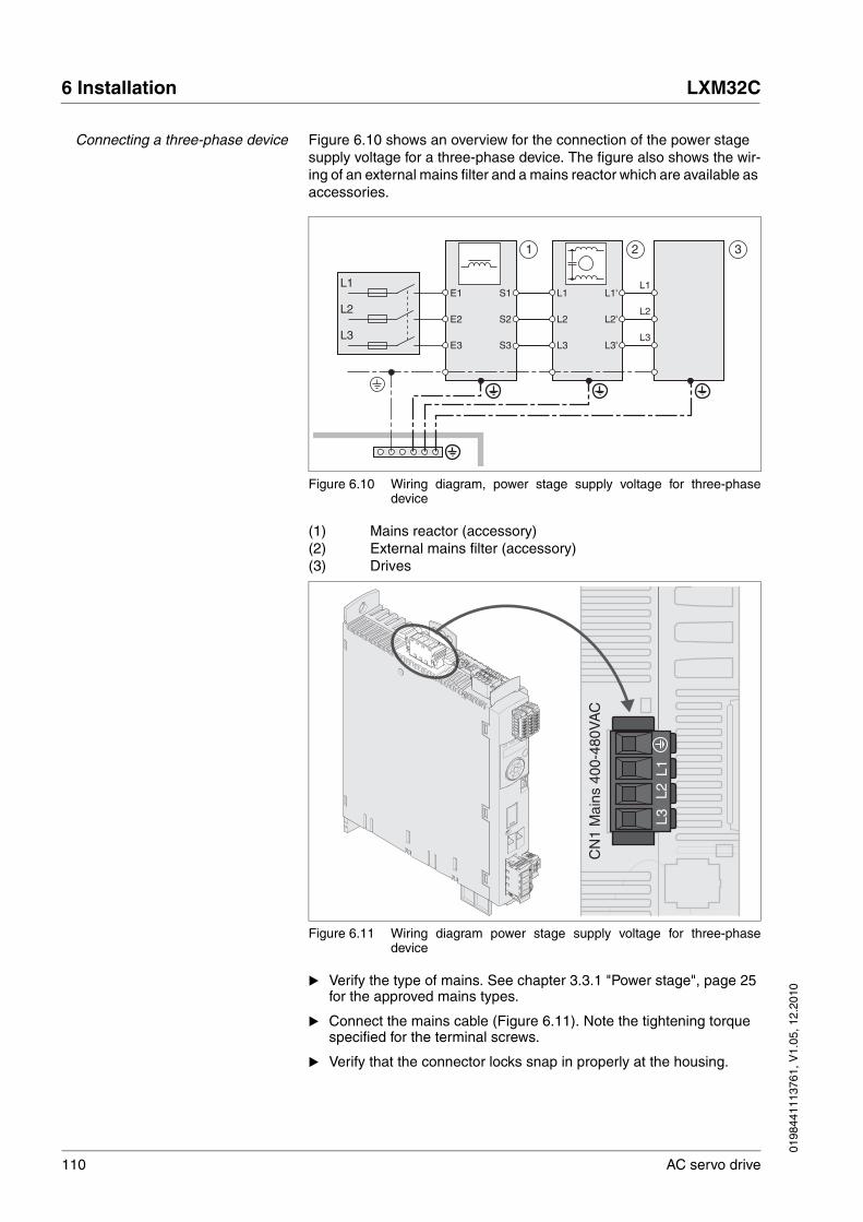
110 AC servo drive
6 Installation LXM32C
0198
4411
1376
1, V
1.05
, 12.
2010
Connecting a three-phase device Figure 6.10 shows an overview for the connection of the power stage supply voltage for a three-phase device. The figure also shows the wir-ing of an external mains filter and a mains reactor which are available as accessories.
Figure 6.10 Wiring diagram, power stage supply voltage for three-phasedevice
(1) Mains reactor (accessory)(2) External mains filter (accessory)(3) Drives
Figure 6.11 Wiring diagram power stage supply voltage for three-phasedevice
� Verify the type of mains. See chapter 3.3.1 "Power stage", page 25 for the approved mains types.
� Connect the mains cable (Figure 6.11). Note the tightening torque specified for the terminal screws.
� Verify that the connector locks snap in properly at the housing.
S2
S3
S1
E3
E2
E1
1 2
L3
3
L2
L1
L3
L2
L1
L3
L2
L1
L3'
L2'
L1'
L1L2
L3
CN
1 M
ains
400
-480
VA
C

0198
4411
1376
1, V
1.05
, 12.
2010
LXM32C 6 Installation
AC servo drive 111
6.2.9 Connecting the motor encoder (CN3)
Function and encoder type The motor encoder is a Hiperface encoder integrated in the motor. It pro-vides the device with information on the motor position (analog and dig-ital).
Note the information on approved motors, see chapter 3.3 "Electrical Data".
Cable specifications See chapter 5.2 "Cables", page 62 for information on the cables.
Shield: Required, both ends grounded
Twisted Pair: Required
PELV: Required
Cable composition: 6*0.14 mm2 + 2*0.34 mm2
(6*AWG 24 + 2*AWG 20)
Maximum cable length: 100 m
Special features: Fieldbus cables are not suitable for connecting encoders.

112 AC servo drive
6 Installation LXM32C
0198
4411
1376
1, V
1.05
, 12.
2010
Wiring diagram
Figure 6.12 Wiring diagram motor encoder
Connecting the motor encoder � Verify that wiring, cables and connected interface meet the PELV requirements.
� Note the EMC requirements for encoder cables, page 58. Use equi-potential bonding conductors for equipotential bonding.
� Connect the connector to CN3, Encoder -1.
� Verify that the connector locks snap in properly at the housing.
Route the cables from the motor and the encoder to the device (start at the motor). Due to the pre-assembled connectors, this direction is often faster and easier.
12345678
1
8
A
B
B
CN
3 En
code
r-1
CN3
A
Pin Signal Motor, pin Pair Meaning I/O
1 COS+ 9 2 Cosine signal I
2 REFCOS 5 2 Reference for cosine signal I
3 SIN+ 8 3 Sine signal I
6 REFSIN 4 3 Reference for sine signal I
4 Data 6 1 Receive data, transmit data I/O
5 Data 7 1 Receive data and transmit data, inverted I/O
7 reserved 4 Not assigned
8 reserved 4 Not assigned
A ENC+10V_OUT 10 5 Encoder supply O
B ENC_0V 11 5 Reference potential for encoder supply
SHLD Shield
0198
4411
1376
1, V
1.05
, 12.
2010
LXM32C 6 Installation
AC servo drive 113
6.2.10 Connection PTO (CN4, Pulse Train Out)
5 V signals are available at the PTO (Pulse Train Out, CN4) output. De-pending on parameter PTO_mode, these signals are ESIM signals (en-coder simulation) or logically fed through PTI input signals (P/D signals, A/B signals, CW/CCW signals). The PTO output signals can be used as PTI input signals for another device. The signal level corresponds to RS422, see chapter 3.3.3.1 "Output PTO (CN4)", page 37. The PTO output supplies 5 V signals, even if the PTI input signal is a 24 V signal.
Cable specifications See chapter 5.2 "Cables", page 62 for information on the cables.
� Use equipotential bonding conductors, see page 62.
� Use pre-assembled cables (page 391) to reduce the risk of wiring errors.
Shield: Required, both ends grounded
Twisted Pair: Required
PELV: Required
Cable composition: 8*0.14 mm2 (8*AWG 24)
Maximum cable length: 100 m
Special features: -
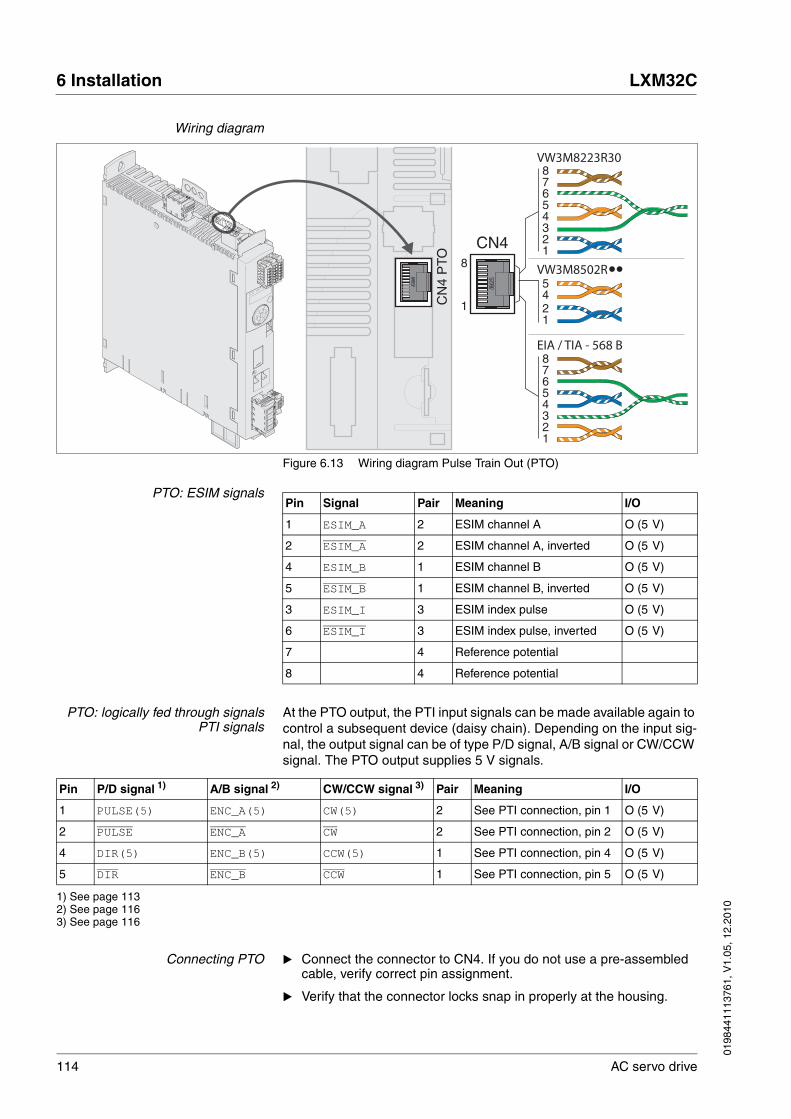
114 AC servo drive
6 Installation LXM32C
0198
4411
1376
1, V
1.05
, 12.
2010
Wiring diagram
Figure 6.13 Wiring diagram Pulse Train Out (PTO)
PTO: ESIM signals
PTO: logically fed through signalsPTI signals
At the PTO output, the PTI input signals can be made available again to control a subsequent device (daisy chain). Depending on the input sig-nal, the output signal can be of type P/D signal, A/B signal or CW/CCW signal. The PTO output supplies 5 V signals.
Connecting PTO � Connect the connector to CN4. If you do not use a pre-assembled cable, verify correct pin assignment.
� Verify that the connector locks snap in properly at the housing.
12345678
12345678
EIA / TIA - 568 B
VW3M8223R30
VW3M8502R
1
8
1245
CN4
CN
4 P
TO
Pin Signal Pair Meaning I/O
1 ESIM_A 2 ESIM channel A O (5 V)
2 ESIM_A 2 ESIM channel A, inverted O (5 V)
4 ESIM_B 1 ESIM channel B O (5 V)
5 ESIM_B 1 ESIM channel B, inverted O (5 V)
3 ESIM_I 3 ESIM index pulse O (5 V)
6 ESIM_I 3 ESIM index pulse, inverted O (5 V)
7 4 Reference potential
8 4 Reference potential
Pin P/D signal 1) A/B signal 2) CW/CCW signal 3) Pair Meaning I/O
1 PULSE(5) ENC_A(5) CW(5) 2 See PTI connection, pin 1 O (5 V)
2 PULSE ENC_A CW 2 See PTI connection, pin 2 O (5 V)
4 DIR(5) ENC_B(5) CCW(5) 1 See PTI connection, pin 4 O (5 V)
5 DIR ENC_B CCW 1 See PTI connection, pin 5 O (5 V)
1) See page 1132) See page 1163) See page 116

0198
4411
1376
1, V
1.05
, 12.
2010
LXM32C 6 Installation
AC servo drive 115
6.2.11 Connection PTI (CN5, Pulse Train In)
P/D (pulse/direction), A/B signals or CW/CCW signals can be con-nected to the PTI connection (Pulse Train In, CN5). It is possible to connect 5 V signals or 24 V signals, see chapter 3.3.3.2 "Input PTI (CN5)", page 38. Pin assignments and cables are different.
Cable specifications PTI See chapter 5.2 "Cables", page 62 for information on the cables.
� Use equipotential bonding conductors, see page 62.
� Use pre-assembled cables (page 391) to reduce the risk of wiring errors.
@ WARNINGUNEXPECTED MOVEMENT
Incorrect or interfered signals as reference values can cause unex-pected movements.
• Use shielded twisted-pair cables.
• If possible, operate the interface with push-pull signals.
• Do not use signals without push-pull in critical applications or in environments subject to interference.
• Do not use signals without push-pull in the case of cable lengths of more than 3 m and limit the frequency to 50 kHz
Failure to follow these instructions can result in death, serious injury or equipment damage.
Shield: Required, both ends grounded
Twisted Pair: Required
PELV: Required
Minimum conductor cross section: 0.14 mm2 (AWG 24)
Maximum cable length: 100 m with RS42210 m with push-pull1 m with open collector
Special features: -

116 AC servo drive
6 Installation LXM32C
0198
4411
1376
1, V
1.05
, 12.
2010
6.2.11.1 Connection assignment PTI 5 V
Figure 6.14 Wiring diagram Pulse Train In (PTI) 5 V
P/D signals 5 V
A/B signals 5 V
CW/CCW signals 5 V
Connecting Pulse Train IN (PTI) 5 V � Connect the connector to CN5. If you do not use a pre-assembled cable, verify correct pin assignment.
� Verify that the connector locks snap in properly at the housing.
CN
5 P
TI
12345678
12345678
EIA / TIA - 568 B
VW3M8223R30
VW3M8502R
1
81245
CN5
Pin Signal Pair Meaning I/O
1 PULSE(5) 2 Pulse 5V I (5 V)
2 PULSE 2 Pulse, inverted I (5 V)
4 DIR(5) 1 Direction 5V I (5 V)
5 DIR 1 Direction, inverted I (5 V)
Pin Signal Pair Meaning I/O
1 ENC_A(5) 2 Encoder channel A 5V I (5 V)
2 ENC_A 2 Encoder channel A, inverted I (5 V)
4 ENC_B(5) 1 Encoder channel B 5V I (5 V)
5 ENC_B 1 Encoder channel B, inverted I (5 V)
Pin Signal Pair Meaning I/O
1 CW(5) 2 Pulse positive 5V I (5 V)
2 CW 2 Pulse positive, inverted I (5 V)
4 CCW(5) 1 Pulse negative 5V I (5 V)
5 CCW 1 Pulse negative, inverted I (5 V)

0198441113761, V1.05, 12.2010
LXM32C 6 Installation
AC servo drive 117
6.2.11.2 Connection assignment PTI 24 V
Note that the wire pairs for 24 V signals require assignments different from those for 5 V signals. Use a cable that complies with the cable specifications and assemble it as shown below.
Figure 6.15 Wiring diagram Pulse Train In (PTI) 24 V
P/D signals 24 V
A/B signals 24 V
CW/CCW signals 24 V
Connecting Pulse Train In (PTI)24 V
� Connect the connector to CN5. Verify correct pin assignment and correct pairing.
� Verify that the connector locks snap in properly at the housing.
CN
5 P
TI
1
8CN5
12345678
Pin Signal Pair Meaning I/O
7 PULSE(24) A Pulse 24V I (24 V)
2 PULSE A Pulse, inverted I (24 V)
8 DIR(24) B Direction 24V I (24 V)
5 DIR B Direction, inverted I (24 V)
Pin Signal Pair Meaning I/O
7 ENC_A(24) A Encoder channel A 24V I (24 V)
2 ENC_A A Encoder channel A, inverted I (24 V)
8 ENC_B(24) B Encoder channel B 24V I (24 V)
5 ENC_B B Encoder channel B, inverted I (24 V)
Pin Signal Pair Meaning I/O
7 CW(24) A Pulse positive 24V I (24 V)
2 CW A Pulse positive, inverted I (24 V)
8 CCW(24) B Pulse negative 24V I (24 V)
5 CCW B Pulse negative, inverted I (24 V)

118 AC servo drive
6 Installation LXM32C
0198
4411
1376
1, V
1.05
, 12.
2010
6.2.12 Connection the controller supply voltage and STO (CN2, DC Supply and STO)
Safety function STO
Information on the signals of the STO safety function can be found in chapter 5.9 "Safety function STO ("Safe Torque Off")". If the safety func-tion is NOT required, the inputs STO_A and STO_B must be connected to +24VDC.
@ DANGERELECTRIC SHOCK CAUSED BY INCORRECT POWER SUPPLY UNIT
The +24VDC supply voltage is connected with many exposed signal connections in the drive system.
• Use a power supply unit that meets the PELV (Protective Extra Low Voltage) requirements.
• Connect the negative output of the power supply unit to PE (ground).
Failure to follow these instructions will result in death or serious injury.
CAUTIONDAMAGE TO CONTACTS
The connection for the controller supply voltage at the product does not have an inrush current limitation. If the voltage is switched on by means of switching of contacts, damage to the contacts or contact welding may result.
• Use a power supply unit that limits the peak value of the output current to a value permissible for the contact.
• Switch the power input of the power supply unit instead of the output voltage.
Failure to follow these instructions can result in equipment dam-age.
@ WARNINGLOSS OF SAFETY FUNCTION
Incorrect usage may cause a hazard due to the loss of the safety func-tion.
• Observe the requirements for using the safety function.
Failure to follow these instructions can result in death or serious injury.

0198
4411
1376
1, V
1.05
, 12.
2010
LXM32C 6 Installation
AC servo drive 119
Cable specifications CN2 See chapter 5.2 "Cables", page 62 for information on the cables.
Properties of spring terminal CN2
The terminals are approved for fine wire conductors and rigid conduc-tors. Observe the maximum permissible connection cross section. Take into account the fact that wire ferrules increase the conductor cross sec-tion. Carefully insert the conductors for maximum current capacity and vibration resistance.
Permissible terminal current ofcontroller supply voltage
• Connection CN2, pins 3 and 7 as well as CN2, pins 4 and 8 (see Figure 6.16) can be used as 24V/0V connections for additional con-sumers.1 Note the maximum permissible terminal current ( "Proper-ties of spring terminal CN2").
• The voltage at the holding brake output depends on the controller supply voltage. Note that the current of the holding brake also flows via this terminal.
• As long as the controller supply voltage is switched on, the position of the motor will remain the same, even if the power stage supply voltage is switched off.
Shield: - 1)
1) See 5.9.3 "Requirements for using the safety function"
Twisted Pair: -
PELV: Required
Minimum conductor cross section: 0.75 mm2 (AWG 18)
Maximum cable length: 100 m
Special features: -
LXM32•...
Maximum terminal current [A] 16 1)
1) Note the maximum permissible terminal current when connecting several devices.
Connection cross section [mm2] 0.5 ... 2.5 (AWG 20 ... AWG 14)
Stripping length [mm] 12 ... 13
1. In the connector, the following pins are connected: pin 1 to pin 5, pin 2 to pin 6, pin 3 to pin 7 and pin 4 to pin 8.
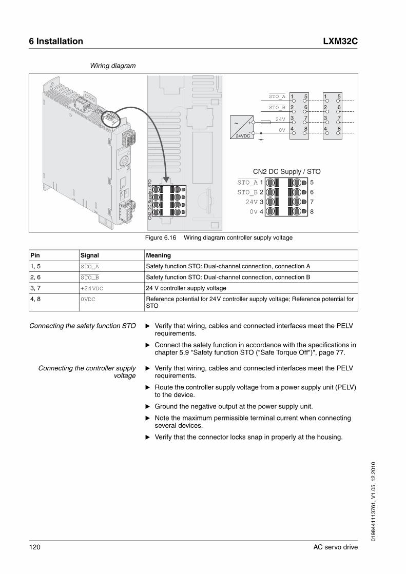
120 AC servo drive
6 Installation LXM32C
0198
4411
1376
1, V
1.05
, 12.
2010
Wiring diagram
Figure 6.16 Wiring diagram controller supply voltage
Connecting the safety function STO � Verify that wiring, cables and connected interfaces meet the PELV requirements.
� Connect the safety function in accordance with the specifications in chapter 5.9 "Safety function STO ("Safe Torque Off")", page 77.
Connecting the controller supplyvoltage
� Verify that wiring, cables and connected interfaces meet the PELV requirements.
� Route the controller supply voltage from a power supply unit (PELV) to the device.
� Ground the negative output at the power supply unit.
� Note the maximum permissible terminal current when connecting several devices.
� Verify that the connector locks snap in properly at the housing.
+
-
~
24VDC
CN
2 D
C S
uppl
y / S
TO STO_A
STO_B
24V
0V
CN2 DC Supply / STO
STO_A
STO_B
24V
0V
1 5
4
3
2
8
7
6
1 5
4
3
2
8
7
6
1 5
4
3
2
8
7
6
Pin Signal Meaning
1, 5 STO_A Safety function STO: Dual-channel connection, connection A
2, 6 STO_B Safety function STO: Dual-channel connection, connection B
3, 7 +24VDC 24 V controller supply voltage
4, 8 0VDC Reference potential for 24V controller supply voltage; Reference potential for STO
0198
4411
1376
1, V
1.05
, 12.
2010
LXM32C 6 Installation
AC servo drive 121
6.2.13 Connecting the analog inputs (CN6)
Cable specifications See chapter 62 for information on the cables.
Properties of spring terminal CN6
Shield: Required, grounded at the device, other end insulated or grounded via capacitor (for example, 10nF)
PELV: Required
Cable composition: 2* 2*0.25 mm2, (2* 2*AWG 22)
Maximum cable length: 10 m
Special features:
LXM32•...
Connection cross section [mm2] 0.2 ... 1.0 (AWG 24 ... AWG 16)
Stripping length [mm] 10
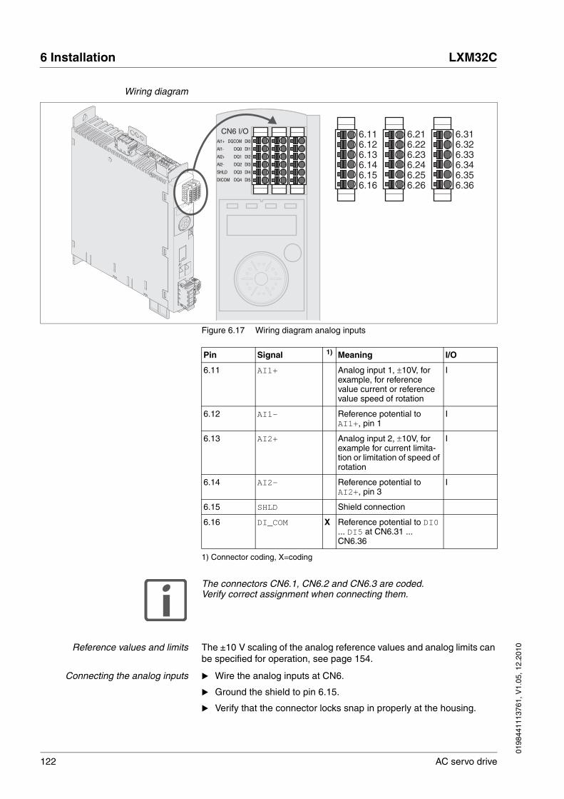
122 AC servo drive
6 Installation LXM32C
0198
4411
1376
1, V
1.05
, 12.
2010
Wiring diagram
Figure 6.17 Wiring diagram analog inputs
The connectors CN6.1, CN6.2 and CN6.3 are coded. Verify correct assignment when connecting them.
Reference values and limits The ±10 V scaling of the analog reference values and analog limits can be specified for operation, see page 154.
Connecting the analog inputs � Wire the analog inputs at CN6.
� Ground the shield to pin 6.15.
� Verify that the connector locks snap in properly at the housing.
6.316.326.336.346.356.36
6.216.226.236.246.256.26
6.116.126.136.146.156.16
CN6 I/OAl1+
DICOM
SHLD
Al2-
Al2+
Al1-
Dl0
Dl1
Dl3
Dl4
Dl5
Dl2
DQCOM
DQ1
DQ3
DQ4
DQ2
DQ0
Pin Signal 1)
1) Connector coding, X=coding
Meaning I/O
6.11 AI1+ Analog input 1, ±10V, for example, for reference value current or reference value speed of rotation
I
6.12 AI1- Reference potential to AI1+, pin 1
I
6.13 AI2+ Analog input 2, ±10V, for example for current limita-tion or limitation of speed of rotation
I
6.14 AI2- Reference potential to AI2+, pin 3
I
6.15 SHLD Shield connection
6.16 DI_COM X Reference potential to DI0 ... DI5 at CN6.31 ... CN6.36

0198
4411
1376
1, V
1.05
, 12.
2010
LXM32C 6 Installation
AC servo drive 123
6.2.14 Connecting the digital inputs/outputs (CN6)
The device has configurable inputs and configurable outputs. The stand-ard assignment and the configurable assignment depends on the se-lected operating mode. For more information, see chapter 8.5.2 "Setting the digital signal inputs and signal outputs".
Cable specifications See chapter 5.2 "Cables" for information on the cables.
Properties of spring terminal CN6
Shield: -
Twisted Pair: -
PELV: Required
Cable composition: 0.25 mm2, (AWG 22)
Maximum cable length: 30 m
Special features:
LXM32•...
Connection cross section [mm2] 0.2 ... 1.0 (AWG 24 ... AWG 16)
Stripping length [mm] 10
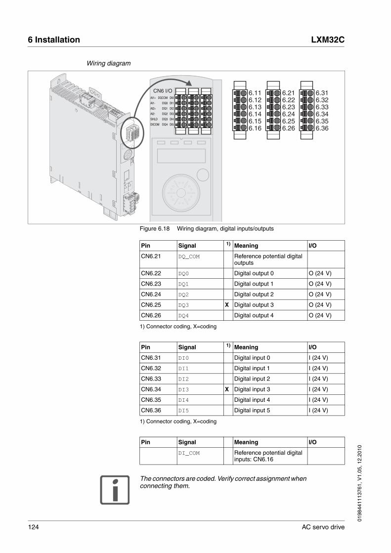
124 AC servo drive
6 Installation LXM32C
0198
4411
1376
1, V
1.05
, 12.
2010
Wiring diagram
Figure 6.18 Wiring diagram, digital inputs/outputs
The connectors are coded. Verify correct assignment when connecting them.
6.316.326.336.346.356.36
6.216.226.236.246.256.26
6.116.126.136.146.156.16
CN6 I/OAl1+
DICOM
SHLD
Al2-
Al2+
Al1-
Dl0
Dl1
Dl3
Dl4
Dl5
Dl2
DQCOM
DQ1
DQ3
DQ4
DQ2
DQ0
Pin Signal 1)
1) Connector coding, X=coding
Meaning I/O
CN6.21 DQ_COM Reference potential digital outputs
CN6.22 DQ0 Digital output 0 O (24 V)
CN6.23 DQ1 Digital output 1 O (24 V)
CN6.24 DQ2 Digital output 2 O (24 V)
CN6.25 DQ3 X Digital output 3 O (24 V)
CN6.26 DQ4 Digital output 4 O (24 V)
Pin Signal 1)
1) Connector coding, X=coding
Meaning I/O
CN6.31 DI0 Digital input 0 I (24 V)
CN6.32 DI1 Digital input 1 I (24 V)
CN6.33 DI2 Digital input 2 I (24 V)
CN6.34 DI3 X Digital input 3 I (24 V)
CN6.35 DI4 Digital input 4 I (24 V)
CN6.36 DI5 Digital input 5 I (24 V)
Pin Signal Meaning I/O
DI_COM Reference potential digital inputs: CN6.16
0198
4411
1376
1, V
1.05
, 12.
2010
LXM32C 6 Installation
AC servo drive 125
The configuration and the standard assignment of the inputs and out-puts are described in chapter 8.5.2 "Setting the digital signal inputs and signal outputs".
Connecting the digital inputs/outputs
� Wire the digital connections to CN6.
� Verify that the connector locks snap in properly at the housing.
6.2.15 Connection of PC with commissioning software CN7)
Cable specifications See chapter 5.2 "Cables", page 62 for information on the cables.
Connecting a PC A PC with commissioning software can be connected for commission-ing. The PC is connected via a bidirectional USB/RS485 converter, see chapter Accessories, page 389.
CAUTIONDAMAGE TO PC
If this commissioning interface at the product is directly connected to a Gigabit Ethernet interface at the PC, the PC interface may be de-stroyed.
• Never directly connect an Ethernet interface to the commission-ing interface of this product.
Failure to follow these instructions can result in equipment dam-age.
Shield: Required, both ends grounded
Twisted Pair: Required
PELV: Required
Cable composition: 8*0.25 mm2, (8*AWG 22)
Maximum cable length: 100 m
Special features: -
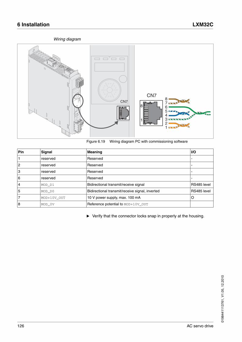
126 AC servo drive
6 Installation LXM32C
0198
4411
1376
1, V
1.05
, 12.
2010
Wiring diagram
Figure 6.19 Wiring diagram PC with commissioning software
� Verify that the connector locks snap in properly at the housing.
1
8
12345678
CN7CN7
Pin Signal Meaning I/O
1 reserved Reserved -
2 reserved Reserved -
3 reserved Reserved -
6 reserved Reserved -
4 MOD_D1 Bidirectional transmit/receive signal RS485 level
5 MOD_D0 Bidirectional transmit/receive signal, inverted RS485 level
7 MOD+10V_OUT 10 V power supply, max. 100 mA O
8 MOD_0V Reference potential to MOD+10V_OUT

0198
4411
1376
1, V
1.05
, 12.
2010
LXM32C 6 Installation
AC servo drive 127
6.3 Checking installation
Verify proper installation:
� Check the mechanical installation of the entire drive system:
• Does the installation meet the specified distance requirements?
• Did you tighten all fastening screws with the specified tightening torque?
� Check the electrical connections and the cabling:
• Did you connect all protective ground conductors?
• Do all fuses have the correct rating; are the fuses of the specified type?
• Did you connect both ends of all live cables or insulate them (no exposed cable ends)?
• Did you properly connect and install all cables and connectors?
• Are the mechanical locks of the connectors correct and effective?
• Did you properly connect the signal wires?
• Are the required shield connections EMC-compliant?
• Did you take all measures for EMC compliance?
� Verify that all covers and seals of the control cabinet are properly installed to meet the required degree of protection.

128 AC servo drive
6 Installation LXM32C
0198
4411
1376
1, V
1.05
, 12.
2010

0198
4411
1376
1, V
1.05
, 12.
2010
LXM32C 7 Commissioning
AC servo drive 129
77 Commissioning
This chapter describes how to commission the product.
7.1 Basic information
An alphabetically sorted overview of the parameters can be found in the chapter "Parameters". The use and the function of some parameters are explained in more detail in this chapter.
@ DANGERELECTRIC SHOCK CAUSED BY INCORRECT USE
The safety function STO (Safe Torque Off) does not cause electric iso-lation. The DC bus voltage is still present.
• Turn off the mains voltage using an appropriate switch to achieve a voltage-free condition.
Failure to follow these instructions will result in death or serious injury.
@ WARNINGUNINTENDED BEHAVIOR
The behavior of the drive system is governed by numerous stored data or settings. Unsuitable settings or data may trigger unexpected movements or responses to signals and disable monitoring functions.
• Do NOT operate the drive system with unknown settings or data.
• Verify that the stored data and settings are correct.
• When commissioning, carefully run tests for all operating states and potential error situations.
• Verify the functions after replacing the product and also after making changes to the settings or data.
• Only start the system if there are no persons or obstructions in the hazardous area.
Failure to follow these instructions can result in death, serious injury or equipment damage.

130 AC servo drive
7 Commissioning LXM32C
0198
4411
1376
1, V
1.05
, 12.
2010
@ WARNINGMOTOR WITHOUT BRAKING EFFECT
If power outage, functions or errors cause the power stage to be switched off, the motor is no longer decelerated in a controlled way and may cause damage.
• Verify the mechanical situation.
• If necessary, use a cushioned mechanical stop or a suitable hold-ing brake.
Failure to follow these instructions can result in death, serious injury or equipment damage.
@ WARNINGUNEXPECTED MOVEMENT
When the drive is operated for the first time, there is a risk of unex-pected movements caused by possible wiring errors or unsuitable pa-rameters.
• Run initial tests without coupled loads.
• Verify that a functioning button for emergency stop is within reach.
• Anticipate movements in the incorrect direction or oscillation of the drive.
• Only start the system if there are no persons or obstructions in the hazardous area.
Failure to follow these instructions can result in death, serious injury or equipment damage.
@ WARNINGHOT SURFACES
The heat sink at the product may heat up to over 100°C (212°F) during operation.
• Avoid contact with the hot heat sink.
• Do not allow flammable or heat-sensitive parts in the immediate vicinity.
• Consider the measures for heat dissipation described.
Failure to follow these instructions can result in death or serious injury.
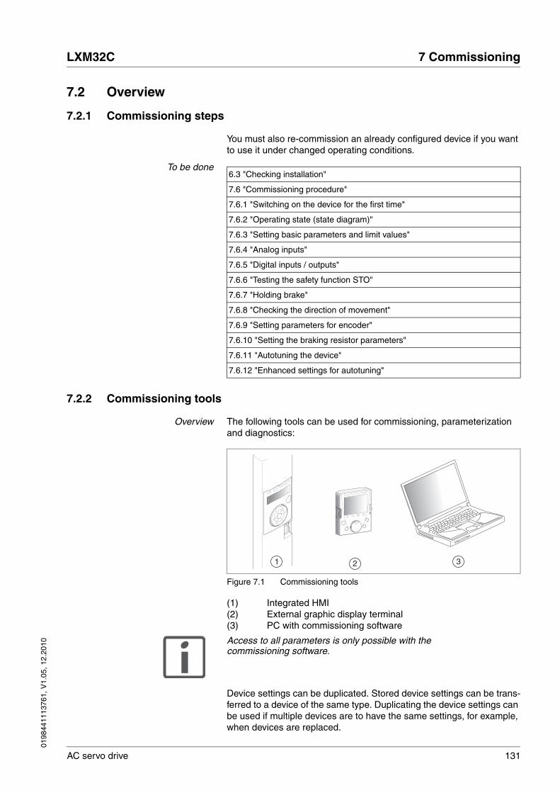
0198
4411
1376
1, V
1.05
, 12.
2010
LXM32C 7 Commissioning
AC servo drive 131
7.2 Overview
7.2.1 Commissioning steps
You must also re-commission an already configured device if you want to use it under changed operating conditions.
To be done
7.2.2 Commissioning tools
Overview The following tools can be used for commissioning, parameterization and diagnostics:
Figure 7.1 Commissioning tools
(1) Integrated HMI(2) External graphic display terminal(3) PC with commissioning software
Access to all parameters is only possible with the commissioning software.
Device settings can be duplicated. Stored device settings can be trans-ferred to a device of the same type. Duplicating the device settings can be used if multiple devices are to have the same settings, for example, when devices are replaced.
6.3 "Checking installation"
7.6 "Commissioning procedure"
7.6.1 "Switching on the device for the first time"
7.6.2 "Operating state (state diagram)"
7.6.3 "Setting basic parameters and limit values"
7.6.4 "Analog inputs"
7.6.5 "Digital inputs / outputs"
7.6.6 "Testing the safety function STO"
7.6.7 "Holding brake"
7.6.8 "Checking the direction of movement"
7.6.9 "Setting parameters for encoder"
7.6.10 "Setting the braking resistor parameters"
7.6.11 "Autotuning the device"
7.6.12 "Enhanced settings for autotuning"
1 2 3
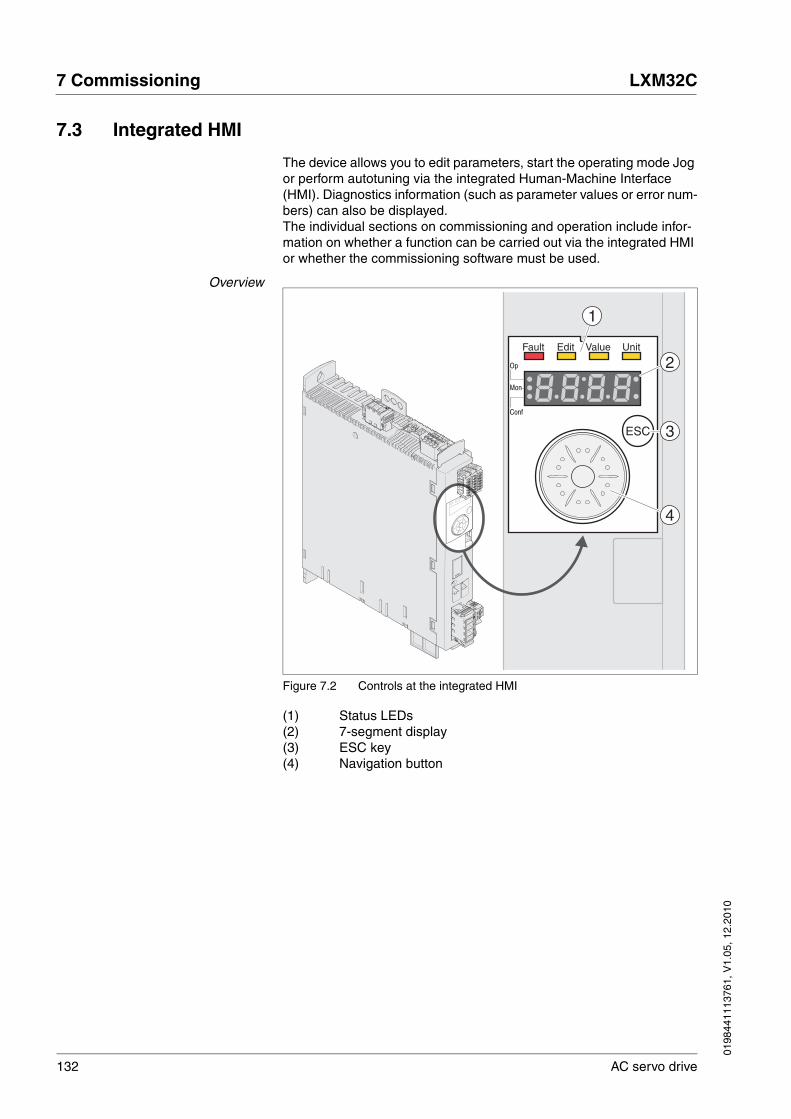
132 AC servo drive
7 Commissioning LXM32C
0198
4411
1376
1, V
1.05
, 12.
2010
7.3 Integrated HMI
The device allows you to edit parameters, start the operating mode Jog or perform autotuning via the integrated Human-Machine Interface (HMI). Diagnostics information (such as parameter values or error num-bers) can also be displayed.The individual sections on commissioning and operation include infor-mation on whether a function can be carried out via the integrated HMI or whether the commissioning software must be used.
Overview
Figure 7.2 Controls at the integrated HMI
(1) Status LEDs(2) 7-segment display(3) ESC key(4) Navigation button
Fault Edit Value Unit
Op
Mon
Conf
ESC
1
3
4
2
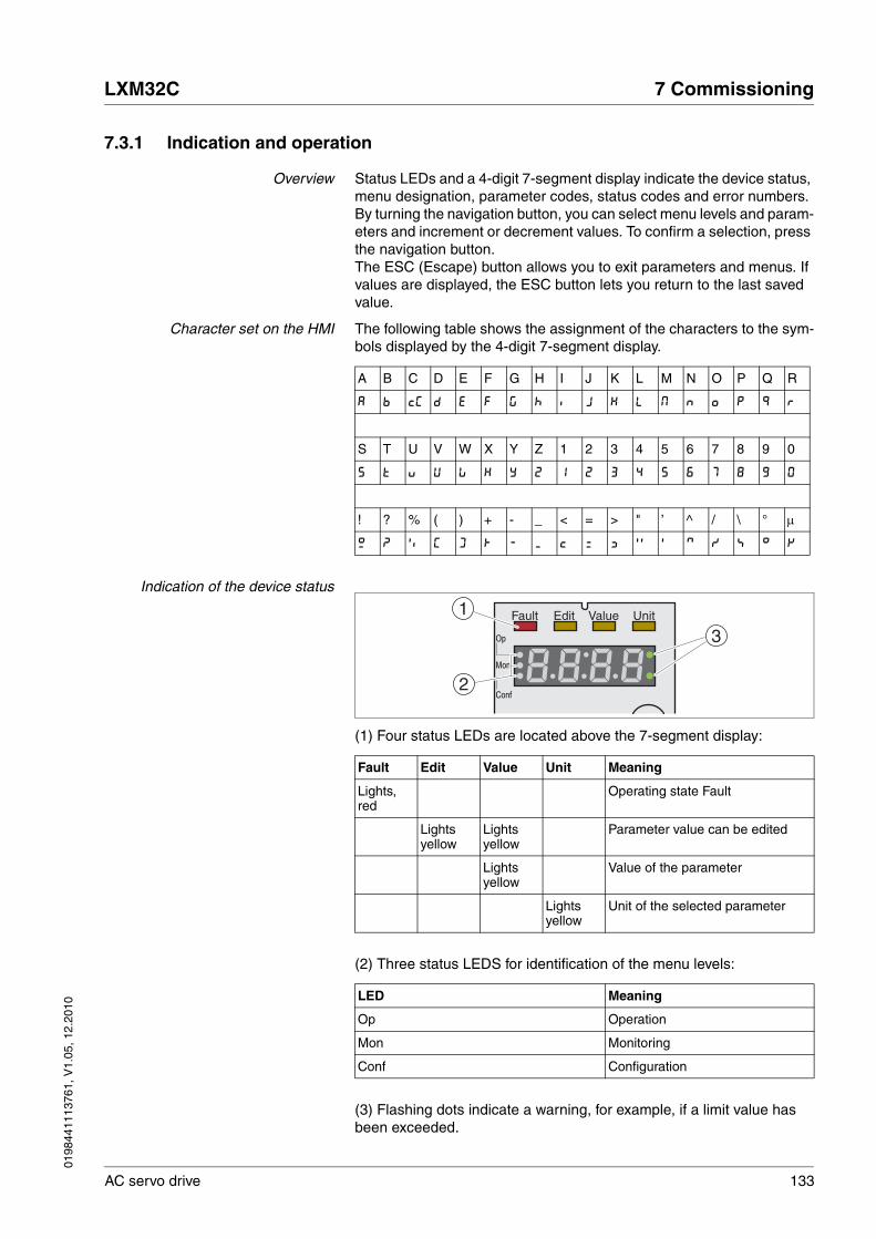
0198
4411
1376
1, V
1.05
, 12.
2010
LXM32C 7 Commissioning
AC servo drive 133
7.3.1 Indication and operation
Overview Status LEDs and a 4-digit 7-segment display indicate the device status, menu designation, parameter codes, status codes and error numbers. By turning the navigation button, you can select menu levels and param-eters and increment or decrement values. To confirm a selection, press the navigation button.The ESC (Escape) button allows you to exit parameters and menus. If values are displayed, the ESC button lets you return to the last saved value.
Character set on the HMI The following table shows the assignment of the characters to the sym-bols displayed by the 4-digit 7-segment display.
Indication of the device status
(1) Four status LEDs are located above the 7-segment display:
(2) Three status LEDS for identification of the menu levels:
(3) Flashing dots indicate a warning, for example, if a limit value has been exceeded.
A B C D E F G H I J K L M N O P Q R
A B cC D E F G H i J K L M N o P Q R
S T U V W X Y Z 1 2 3 4 5 6 7 8 9 0
S T u V W X Y Z 1 2 3 4 5 6 7 8 9 0
! ? % ( ) + - _ < = > " ’ ^ / \ ° μ
! ?“ % ( ) + - _ < = > " ` ^ / \ ° μ
Fault Edit Value Unit Meaning
Lights, red
Operating state Fault
Lights yellow
Lights yellow
Parameter value can be edited
Lights yellow
Value of the parameter
Lights yellow
Unit of the selected parameter
LED Meaning
Op Operation
Mon Monitoring
Conf Configuration
Fault Edit Value Unit
Op
Mon
Conf
3
1
2

134 AC servo drive
7 Commissioning LXM32C
0198
4411
1376
1, V
1.05
, 12.
2010
Navigation button The navigation button can be turned and pressed. There are two types of pressing: short pressing (≤1 s) and long pressing (≥3 s).
Turn the navigation button to do the following:
• Go to the next or previous menu
• Go to the next or previous parameter
• Increment or decrement values
Briefly press the navigation button to do the following:
• Call the selected menu
• Call the selected parameter
• Save the current value to the EEPROM
Hold down the navigation button to do the following:
• Display a description of the selected parameter
• Display the unit of the selected parameter
Access channels The product can be addressed via different access channels. See chap-ter 8.1 "Access channels" for additional information.
7.3.2 Menu structure
Overview The integrated HMI is menu-driven. The following illustration shows the top level of the menu structure.
Figure 7.3 HMI menu structure
The level below the top level contains the parameters belonging to the respective menu items. To facilitate access, the parameter tables also specify the menu path, for example op→jog-.
Fault Edit Value UnitOp
Mon
Conf
Fault Edit Value UnitOp
Mon
Conf
Fault Edit Value UnitOp
Mon
Conf
Fault Edit Value UnitOp
Mon
Conf
Fault Edit Value UnitOp
Mon
Conf
Fault Edit Value UnitOp
Mon
Conf
Fault Edit Value UnitOp
Mon
Conf
ESC
<1s
<1s
ESC
<1s
ESC
<1s
ESCESC ESC
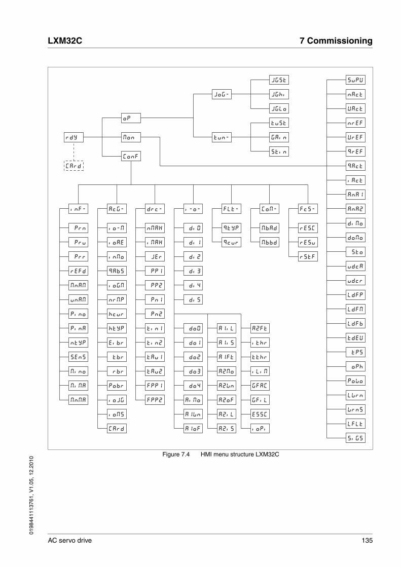
0198
4411
1376
1, V
1.05
, 12.
2010
LXM32C 7 Commissioning
AC servo drive 135
Figure 7.4 HMI menu structure LXM32C
rdy
Jog-
tun-
Card
op
mon
inf- acg- drc- i-o- flt- Com-
jgst
jghi
jglo
tust
gain
stin
fcs-
Conf
VAct
nref
supv
nAct
vref
qref
Ana1
Ana2
qact
iAct
diMo prn
refd
mnam
pru
prr
unam
pino
pina
sens
ntyp
mino
mima
mnma
io-m
qabs
iogM
ioae
inmo
nrmp
hcur
htyp
tbr
eibr
rbr
pobr
iojg
ioms
Card
nmax
pp1
pp2
imax
jer
Pn1
Pn2
tin1
tau1
tin2
tau2
fpp1
fpp2
di0
di1
di2
di3
di4
di5
qtyP
qcur
MbAd
Mbbd
rESC
rESu
rStF
domo
udcr
ldfp
sto
udca
ldfm
ldfb
tdev
oph
tps
powo
lwrn
wrns
lflt
sigs
AiMo
do1
A1Wn
A1oF
A1iL
A1Ft
A1iS
A2Mo
A2Wn
A2oF
A2iL
A2iS
A2Ft
ithr
tthr
iLiM
GFiL
GFAC
ESSC
ioPi
do0
do2
do3
do4

136 AC servo drive
7 Commissioning LXM32C
0198
4411
1376
1, V
1.05
, 12.
2010
HMI menu op Description
op Operating mode (Operation)
Jog- Operating mode Jog
tun- Autotuning
HMI menu Jog- Description
Jog- Operating mode Jog
jgst Start operating mode Jog
jghi Velocity for fast movement
jglo Velocity for slow movement
HMI menu tun- Description
tun- Autotuning
tust Start autotuning
gain Global gain factor (affects parameter set 1)
stin Direction of movement for Autotuning
HMI menu Mon Description
Mon Monitoring (Monitoring)
Supu HMI display when motor moves
nact Actual speed of rotation
Vact Actual velocity
nref Reference speed of rotation
Vref Reference velocity
Qref Reference motor current (q component, generating torque)
qact Actual motor current (q component, generating torque)
iact Total motor current
ana1 Analog 1: Value of input voltage
ana2 Analog 2: Value of input voltage
dimo Status of digital inputs
domo Status of digital outputs
sto Status of the inputs for the safety function STO
udca Voltage at DC bus
udcr Degree of utilization of DC bus voltage
ldfp Current load of power stage
ldfm Current load of motor
ldfb Current load on braking resistor
tdeV Current device temperature
tps Current power stage temperature
oph Operating hours counter
Polo Number of power on cycles
lwrn Number of last warning (error class 0)
wrns Saved warnings, bit-coded

0198
4411
1376
1, V
1.05
, 12.
2010
LXM32C 7 Commissioning
AC servo drive 137
lflt Error causing a stop (error classes 1 to 4)
sigs Saved status of monitoring signals
HMI menu Mon Description
HMI menu Conf Description
Conf Configuration (Configuration)
inf- Information/Identification (INFormation / Identification)
acg- Axis configuration (Axis Configuration)
drc- Device configuration (DRive Configuration)
i-o- Configurable inputs/outputs (In Out)
flt- Error indication
Com- Communication (COMmunication)
fcs- Restore factory settings (default values) (Factrory Settings)
HMI menu INF- Description
Inf- Information/Identification (INFormation / Identification)
prn Firmware program number
Pru Firmware version number
prr Firmware revision number
refd Product Name
Mnam Type
unam User application name
pino Nominal current of power stage
pina Maximum current of power stage
ntyp Motor type
sens Encoder type of motor
mino Nominal current of motor
mima Maximum current of motor
mnma Maximum permissible speed of rotation/velocity of motor
HMI menu acg- Description
acg- Axis configuration (Axis Configuration)
io-m Operating mode
ioae Enabling the power stage at PowerOn
inmo Inversion of direction of movement
qabs Simulation of absolute position at power cycling
iogm Processing mode for operating mode Electronic Gear
nrmp Maximum velocity of the motion profile for velocity
hcur Current value for Halt
htyp Halt option code
eibr Selection of internal or external braking resistor
tbr Maximum permissible activation duration of external braking resistor
rbr Resistance value of external braking resistor

138 AC servo drive
7 Commissioning LXM32C
0198
4411
1376
1, V
1.05
, 12.
2010
pobr Nominal power of external braking resistor
iojg Selection of jog method
ioms Operating mode for signal input function Operating Mode Switch
Card Memory card management
HMI menu acg- Description
HMI menu DRC- Description
drC- Device configuration (DRive Configuration)
nmax Velocity limitation
imax Current limitation
jer Jerk limitation of the motion profile for velocity
pp1 Position controller P gain
pp2 Position controller P gain
pn1 Velocity controller P gain
pn2 Velocity controller P gain
tin1 Velocity controller integral action time
tin2 Velocity controller integral action time
tau1 Filter time constant of reference velocity value filter
tau2 Filter time constant of reference velocity value filter
fpp1 Velocity feed-forward control
fpp2 Velocity feed-forward control
HMI menu I-O- Description
i-o- Configurable inputs/outputs (In Out)
di0 Function Input DI0
di1 Function Input DI1
di2 Function Input DI2
di3 Function Input DI3
di4 Function Input DI4
di5 Function Input DI5
do0 Function Output DQ0
do1 Function Output DQ1
do2 Function Output DQ2
do3 Function Output DQ3
do4 Function Output DQ4
a1mo Analog 1: Type of usage
a1wn Analog 1: Zero voltage window
a1of Analog 1: Offset voltage
a1il Analog 1: Limitation of current at 10 V
a1is Analog 1: Target torque at 10 V in operating mode Profile Torque
a1ft Analog 1: Filter time constant
a2mo Analog 2: Type of usage
A2wn Analog 2: Zero voltage window

0198
4411
1376
1, V
1.05
, 12.
2010
LXM32C 7 Commissioning
AC servo drive 139
A2of Analog 2: Offset voltage
A2il Analog 2: Limitation of current at 10 V
A2is Analog 2: Target torque at 10 V in operating mode Profile Torque
A2ft Analog 2: Filter time constant
ithr Monitoring of threshold value for current
tthr Monitoring of time window
ilin Current limitation via input
gfac Selection of special gear ratios
gfil Activation of jerk filter processing
essc Resolution of encoder simulation
iopi Selection of signal type for PTI interface
HMI menu I-O- Description
HMI menu FLT- Description
FLt- Error indication
qtyp Quick Stop option code
qcur Current value for Quick Stop
HMI menu Com- Description
Com- Communication (COMmunication)
mbad Modbus address
mbbd Modbus Baud rate
HMI menu fcs- Description
fcs- Restore factory settings (default values) (Factrory Settings)
resc Reset controller parameters
resu Reset user parameters
rstf Restore factory settings (default values)

140 AC servo drive
7 Commissioning LXM32C
0198
4411
1376
1, V
1.05
, 12.
2010
7.3.3 Making settings
Displaying and setting parameters The figure below shows an example of displaying a parameter (second level) and entering or selecting a parameter value (third level).
Figure 7.5 Integrated HMI, example of setting a parameter
� The parameter imax (iMax) is shown on the 7-segment display, see Figure 7.5.
� Press the navigation button for a longer period of time to display a parameter description.
� The parameter description is displayed in the form of horizontally scrolling text.
� Briefly press the navigation button to display the current value of the selected parameter.
� The Value status LED lights up and the current parameter value is displayed.
� Press the navigation button for a longer period of time to display the unit of the current parameter value.
� As long as the navigation button is held down, the status LEDs Value and Unit light. The unit of the current parameter value is dis-played. Once you release the navigation button, the current param-eter value is displayed again and the status LED Value lights.
� Briefly press the navigation button to activate the Edit mode which allows you to modify parameter values.
� The Edit and Value status LEDs light up and the current parameter value is displayed.
Fault Edit Value UnitOp
Mon
Conf
Fault Edit Value UnitOp
Mon
Conf
Fault Edit Value UnitOp
Mon
Conf
Fault Edit Value UnitOp
Mon
Conf
ESCESC
ESC
Fault Edit Value UnitOp
Mon
Conf
<1s
<1s
<1s
<2s

0198
4411
1376
1, V
1.05
, 12.
2010
LXM32C 7 Commissioning
AC servo drive 141
� Turn the navigation button to change the value. The increments and the limit value for each parameter are pre-defined.
� The Edit and Value status LEDs light and the selected parameter value is displayed.
� Briefly press the navigation button to save the changed parameter value.
If you do not want to save the changed parameter value, press the ESC button to cancel. The display returns to the original value.
� The displayed parameter value flashes once; the changed parame-ter value is written to the EEPROM.
� Press ESC to return to the menu
Setting the 7-segment display By default, the current operating state is displayed by the 4-digit 7-seg-ment display, see page 193. You can set the following via the menu item drc- / supv:
• stat displays the current operating state
• vact displays the current velocity of the motor
• iact displays the current motor current
A change only becomes active when the power stage is disabled.

142 AC servo drive
7 Commissioning LXM32C
0198
4411
1376
1, V
1.05
, 12.
2010
7.4 External graphic display terminal
The external graphic display terminal is only designed for commission-ing drives.
Figure 7.6 External graphic display terminal
(1) Display(2) Navigation button(3) STOP/RESET key(4) RUN key(5) FWD/REV key(6) ESC key(7) Function keys F1 ... F4
Depending on the firmware version of the external graphic display ter-minal, the information may be represented differently. Use the latest firmware version.
If you have any questions please contact your sales office. Your sales office staff will be happy to give you the name of a customer service office in your area.
1
2
3
54
6
7
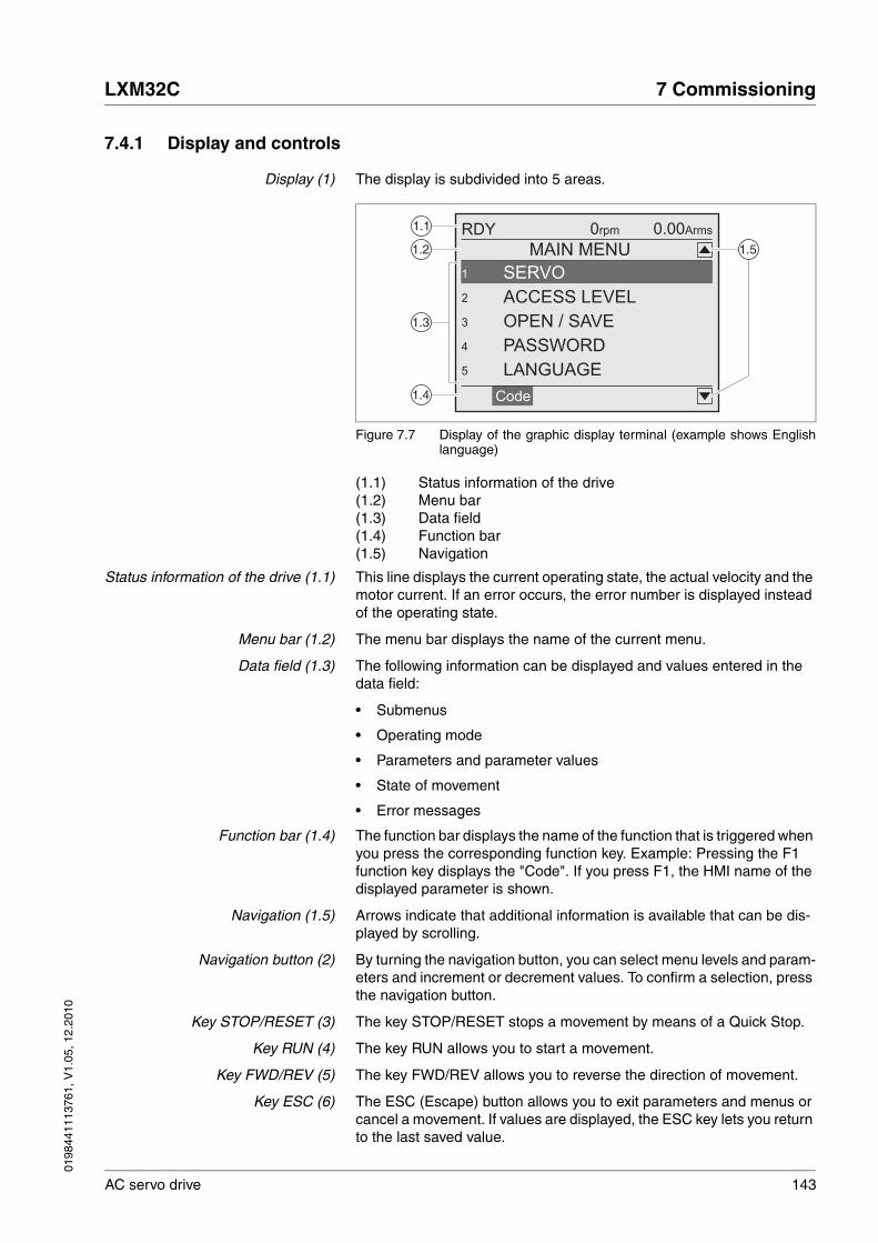
0198
4411
1376
1, V
1.05
, 12.
2010
LXM32C 7 Commissioning
AC servo drive 143
7.4.1 Display and controls
Display (1) The display is subdivided into 5 areas.
Figure 7.7 Display of the graphic display terminal (example shows Englishlanguage)
(1.1) Status information of the drive(1.2) Menu bar(1.3) Data field(1.4) Function bar(1.5) Navigation
Status information of the drive (1.1) This line displays the current operating state, the actual velocity and the motor current. If an error occurs, the error number is displayed instead of the operating state.
Menu bar (1.2) The menu bar displays the name of the current menu.
Data field (1.3) The following information can be displayed and values entered in the data field:
• Submenus
• Operating mode
• Parameters and parameter values
• State of movement
• Error messages
Function bar (1.4) The function bar displays the name of the function that is triggered when you press the corresponding function key. Example: Pressing the F1 function key displays the "Code". If you press F1, the HMI name of the displayed parameter is shown.
Navigation (1.5) Arrows indicate that additional information is available that can be dis-played by scrolling.
Navigation button (2) By turning the navigation button, you can select menu levels and param-eters and increment or decrement values. To confirm a selection, press the navigation button.
Key STOP/RESET (3) The key STOP/RESET stops a movement by means of a Quick Stop.
Key RUN (4) The key RUN allows you to start a movement.
Key FWD/REV (5) The key FWD/REV allows you to reverse the direction of movement.
Key ESC (6) The ESC (Escape) button allows you to exit parameters and menus or cancel a movement. If values are displayed, the ESC key lets you return to the last saved value.
1.1
1.2
1.3
1.5
1.4
RDY
MAIN MENU
0rpm 0.00Arms
PASSWORD
OPEN / SAVE
ACCESS LEVEL
LANGUAGE
Code
SERVO1
5
4
3
2

144 AC servo drive
7 Commissioning LXM32C
0198
4411
1376
1, V
1.05
, 12.
2010
Function keys F1 ... F4 (7) The assignment of the function keys F1 .... F4 depends on the context. The function bar displays the name of the function triggered when the corresponding function key is pressed.
7.4.2 Connecting the external graphic display terminal to LXM32
The external graphic display terminal is an accessory for the drive, see chapter 12.1 "Commissioning tools", page 389. The external graphic display terminal is connected to CN7 (commissioning interface). Only use the cable shipped with the external graphic display terminal to con-nect it. If the external graphic display terminal is connected to LXM32, the integrated HMI is deactivated. The integrated HMI shows disp (Dis-play).
7.4.3 Using the external graphic display terminal
The following 2 examples show you how to use the external graphic dis-play terminal.
Example 'Setting the Language' In this example, you set the desired language for the external graphic display terminal. The drive must have been fully installed and the supply voltage must be on.
� The external graphic display terminal has been connected to CN7 and the main menu is displayed.
� Rotate the navigation button until item 5 (LANGUAGE) is high-lighted.
� Press the navigation button to confirm the selection.
� The menu bar shows the selected function (5 LANGUAGE). The data field displays the selected value, in this case the selected lan-guage.
� Press the navigation button to change the value.
� The menu bar displays the selected function "Language". The sup-ported languages are shown in the data field.
� Turn the navigation button to select the desired language.
� The currently active language is highlighted by a check.
� Press the navigation button to confirm the selected value.
� The menu bar displays the selected function "Language". The selected language is shown in the data field.
� Press ESC to return to the main menu.
� The main menu is displayed in the selected language.
0198
4411
1376
1, V
1.05
, 12.
2010
LXM32C 7 Commissioning
AC servo drive 145
Example 'Using Operating ModeJog'
This example starts a movement in the operating mode Jog. The drive must have been fully installed. Commission the drive as per chapter 7.6 "Commissioning procedure". The following procedure corresponds to chapter .7.6.8 "Checking the direction of movement".
� The external graphic display terminal has been connected to CN7 and the main menu is displayed. The desired language has been set.
� Rotate the navigation button until item 1 (SERVO) is highlighted.
� Press the navigation button to confirm the selection.
� The menu bar shows the selected function (1 SERVO). The data field displays the submenu of the selected function (1 SERVO).
� Rotate the navigation button until item 1.4 (OPERATION) is high-lighted and press the navigation button to confirm the selection.
� The menu bar shows the selected function (1.4 OPERATION). The data field displays the supported operating modes in a submenu.
� Rotate the navigation button until item 1.4.1 (JOG) is highlighted and press the navigation button to confirm the selection.
� The menu bar shows the selected function (1.4.1 JOG). The data field displays "Op. mode Jog" and the parameters and parameter values for the operating mode
� Rotate the navigation button until the item "Op. mode Jog" is high-lighted and press the navigation button to confirm the selection.
� The data field displays "JOG →" (Jog, slow movement in positive direction).
� Rotate the navigation button to change the (slow: →, ← fast: →→, ←←) and the direction of movement (positive direction of move-ment: →, →→, negative direction of movement: ←,←←). You can also use the FWD/REV key to change the direction of movement.
� Press the navigation button or the RUN key to enable the power stage.
� Press the navigation button or the RUN key to start a movement.
� The movement continues as long as you hold down the navigation button / the RUN key or until you press the STOP/RESET key. You can neither change the velocity nor the direction of movement dur-ing the movement.
� To stop the movement, press the STOP/RESET key or release the navigation button / the RUN key.
� Press the ESC key to disable the power stage.
� Power stage is disabled.
� Press ESC 3 times to return to the main menu.
� Each time you press ESC you go back by one menu level.
146 AC servo drive
7 Commissioning LXM32C
0198
4411
1376
1, V
1.05
, 12.
2010
7.5 Commissioning software
The commissioning software has a graphic user interface and is used for commissioning, diagnostics and testing settings.
• Tuning of the controller parameters via a graphical user interface
• Comprehensive set of diagnostics tools for optimization and mainte-nance
• Long-term recording for evaluation of the performance
• Testing the input and output signals
• Tracking signals on the screen
• Archiving of device settings and recordings with export function for further processing in other applications
See page 125 for details on connecting a PC to the device.
Online help The commissioning software offers help functions, which can be ac-cessed via "? - Help Topics" or by pressing the F1 key.

0198
4411
1376
1, V
1.05
, 12.
2010
LXM32C 7 Commissioning
AC servo drive 147
7.6 Commissioning procedure
@ WARNINGUNINTENDED BEHAVIOR
The behavior of the drive system is governed by numerous stored data or settings. Unsuitable settings or data may trigger unexpected movements or responses to signals and disable monitoring functions.
• Do NOT operate the drive system with unknown settings or data.
• Verify that the stored data and settings are correct.
• When commissioning, carefully run tests for all operating states and potential error situations.
• Verify the functions after replacing the product and also after making changes to the settings or data.
• Only start the system if there are no persons or obstructions in the hazardous area.
Failure to follow these instructions can result in death, serious injury or equipment damage.
@ WARNINGUNINTENDED BEHAVIOR CAUSED BY ACCESS CONTROL
Improper use of access control may cause commands to be triggered or blocked.
• Verify that no unintended behavior is caused as a result of ena-bling or disabling exclusive access.
• Verify that impermissible access is blocked.
• Verify that required access is available.
Failure to follow these instructions can result in death, serious injury or equipment damage.

148 AC servo drive
7 Commissioning LXM32C
0198
4411
1376
1, V
1.05
, 12.
2010
7.6.1 Switching on the device for the first time
Duplicating device settings A memory card or the commissioning software allows you duplicate de-vice settings. See chapter 7.9 "Duplicating existing device settings", page 188 for additional information.
Automatic reading of the motor datarecord
When the device is switched on and if an encoder is connected to CN3, the device automatically reads the electronic nameplate from the Hiper-face encoder. The record is checked and written to the EEPROM.
The record contains technical information on the motor such as nominal torque and peak torque, nominal current, nominal velocity and number of pole pairs. The record cannot be changed by the user. Without this in-formation, the device is not ready for operation.
Preparation If the device is not to be commissioned exclusively via the HMI, a PC with the commissioning software must be connected.
Switching on the device � The power stage supply voltage is switched off.
� Switch on the controller supply voltage.
� The device goes through an initialization routine, all LEDs are tested, all segments of the 7-segment display and the status LEDs light up.
If a memory card is in the the slot of the device, the message CARD is dis-played by the 7-segment display for a short period of time. This indicates that a memory card has been detected. If the message CARD is perma-nently displayed by the 7-segment display, there are differences be-tween the content of the memory card and the parameter values stored in the device. See chapter 7.8 "Memory Card", page 185 for additional information.
After the initialization, the device is ready for operation. The device is in the operating mode Jog. See chapter 8.3 "Operating modes", page 198 for changing operating modes.

0198
4411
1376
1, V
1.05
, 12.
2010
LXM32C 7 Commissioning
AC servo drive 149
7.6.2 Operating state (state diagram)
After switching on and when an operating mode is started, the product goes through a number of operating states.
The state diagram (state machine) shows the relationships between the operating states and the state transitions.
The operating states are monitored and influenced by internal monitor-ing functions and system functions such as temperature monitoring or current monitoring.
Graphical representation The state diagram is represented as a flow chart.
Figure 7.8 State diagram
Operating states and statetransitions
See page 193 for detailed information on operating states and state transitions.
T10
T12
T15
3
4
6
5
rdy
Son
dis
T11
T16
T4
T3
T9 T2 T7
T1
nrdy
INIT1
2T0
T13
Fault
fLt
fLt
8
9
T14
7
Stop 8888
8888
HaLt
rUnOperationEnabled
ReadyTo Switch On
Switched On
Switch OnDisabled
Not ReadyTo Switch On
Fault ReactionActive
Quick Stop Active
Switching on
Operating state State transition
Start
HALT
Motor under current
Motor without current
Error class 2, 3, (4)Error class 1
Error
150 AC servo drive
7 Commissioning LXM32C
0198
4411
1376
1, V
1.05
, 12.
2010
7.6.3 Setting basic parameters and limit values
Prepare a list with the parameters required for the functions used.
Controller parameter sets This device allows you to use two controller parameter sets. It is possible to switch form one set of controller parameters to the other during oper-ation. The active controller parameter set is selected with the parameter CTRL_SelParSet.
The corresponding parameters are CTRL1_xx for the first controller pa-rameter set and CTRL2_xx for the second controller parameter set. The following descriptions use the notation CTRL1_xx (CTRL2_xx) if there are no functional differences between the two controller parameter sets.
Setting limit values Suitable limit values must be determined and calculated on the basis of the system and motor data. As long as the motor is operated without loads, the default settings do not need to be changed.
Parameter nameHMI menuHMI name
Description UnitMinimum valueFactory settingMaximum value
Data typeR/WPersistentExpert
Parameter address via fieldbus
CTRL_SelParSet Selection of controller parameter set (non-persistent)
Coding see parameter: CTRL_PwrUpParSet
Changed settings become active immedi-ately.
-012
UINT16R/W--
Modbus 4402
_CTRL_ActParSet Active controller parameter set
Value 1: Controller parameter set 1 is activeValue 2: Controller parameter set 2 is active
A controller parameter set is active after the time for the parameter switching (CTRL_ParChgTime) has elapsed.
----
UINT16R/---
Modbus 4398
CTRL_ParChgTime Period of time for parameter switching
In the case of parameter set switching, the values of the following parameters are changed gradually:- CTRL_KPn- CTRL_TNn- CTRL_KPp- CTRL_TAUnref- CTRL_TAUiref- CTRL_KFPp
Such a parameter switching can be caused by - change of the active controller parameter set- change of the global gain- change of any of the parameters listed above- switching off the integral term of the velocity controller
Changed settings become active immedi-ately.
ms002000
UINT16R/Wper.-
Modbus 4392

0198
4411
1376
1, V
1.05
, 12.
2010
LXM32C 7 Commissioning
AC servo drive 151
Current limitation The maximum motor current can be set with the parameter CTRL_I_max.
The maximum current for the "Quick Stop" function can be limited with the parameter LIM_I_maxQSTP and for the "Halt" function with the pa-rameter LIM_I_maxHalt.
� Use the parameter CTRL_I_max to set the maximum motor cur-rent.
� Use the parameter LIM_I_maxQSTP to set the maximum motor current for the "Quick Stop" function.
� Use the parameter LIM_I_maxHalt to set the maximum motor current for the "Halt" function.
The motor can be decelerated via a deceleration ramp or the maximum current for the functions "Quick Stop" and "Halt".
The device limits the maximum permissible current on the basis of the motor data and the device data. Even if the value entered for the maxi-mum current in the parameter CTRL_I_max is too high, the value is lim-ited.
Parameter nameHMI menuHMI name
Description UnitMinimum valueFactory settingMaximum value
Data typeR/WPersistentExpert
Parameter address via fieldbus
CTRL_I_max
ConF → drC-
iMAX
Current limitation
During operation, the actual current limit is one of the following values (whichever is low-est): - CTRL_I_max- M_I_max- PA_I_max- Current limitation via analog input- Current limitation via digital inputLimitations caused by I2t monitoring are also taken into account.
Default: PA_I_max at 8 kHz PWM frequency and 230/480 V mains voltage
In increments of 0.01 Arms.
Changed settings become active immedi-ately.
Arms0.00-300.00
UINT16R/Wper.-
Modbus 4376

152 AC servo drive
7 Commissioning LXM32C
0198
4411
1376
1, V
1.05
, 12.
2010
LIM_I_maxQSTP
ConF → FLt-
qcur
Current value for Quick Stop
This value is only limited by the minimum/maximum value range (no limitation of this value by motor/power stage).
In the case of a Quick Stop, the actual cur-rent limit (_Imax_actual) is one of the follow-ing values (whichever is lowest):- LIM_I_maxQSTP- M_I_max- PA_I_max
Further current reductions caused by I2t monitoring are also taken into account dur-ing a Quick Stop.
Default: PA_I_max at 8 kHz PWM frequency and 230/480 V mains voltage
In increments of 0.01 Arms.
Changed settings become active immedi-ately.
Arms---
UINT16R/Wper.-
Modbus 4378
LIM_I_maxHalt
ConF → ACG-
hcur
Current value for Halt
This value is only limited by the minimum/maximum value range (no limitation of this value by motor/power stage).
In the case of a Halt, the actual current limit (_Imax_actual) is one of the following values (whichever is lowest):- LIM_I_maxHalt- M_I_max - PA_I_max
Further current reductions caused by I2t monitoring are also taken into account dur-ing a Halt.
Default: PA_I_max at 8 kHz PWM frequency and 230/480 V mains voltage
In increments of 0.01 Arms.
Changed settings become active immedi-ately.
Arms---
UINT16R/Wper.-
Modbus 4380
Parameter nameHMI menuHMI name
Description UnitMinimum valueFactory settingMaximum value
Data typeR/WPersistentExpert
Parameter address via fieldbus
0198
4411
1376
1, V
1.05
, 12.
2010
LXM32C 7 Commissioning
AC servo drive 153
Velocity limitation The parameter CTRL_v_max can be used to limit the maximum velocity.
� Use the parameter CTRL_v_max to set the maximum velocity of the motor.
Parameter nameHMI menuHMI name
Description UnitMinimum valueFactory settingMaximum value
Data typeR/WPersistentExpert
Parameter address via fieldbus
CTRL_v_max
ConF → drC-
nMAX
Velocity limitation
During operation, the actual velocity limit is one of the following values (whichever is low-est): - CTRL_v_max- M_n_max- Velocity limitation via analog input- Velocity limitation via digital input
Changed settings become active immedi-ately.
usr_v1132002147483647
UINT32R/Wper.-
Modbus 4384
154 AC servo drive
7 Commissioning LXM32C
0198
4411
1376
1, V
1.05
, 12.
2010
7.6.4 Analog inputs
The two analog inputs are referred to as AI1 and AI2. The following de-scriptions use the notation AI1 (AI2) if there are no functional differ-ences between the two inputs.
Analog inputs Analog input voltages between -10 Vdc and +10 Vdc can be read via the analog inputs. The current voltage value at AI1+ (AI2+) can be read with the parameter _AI1_act (_AI2_act).
� Power stage supply voltage is switched off.Controller supply voltage is switched on.
� Apply a voltage in the range from ±10Vdc to the analog input AI1 (AI2).
� Check the applied voltage with the parameter _AI1_act (_AI2_act).
Offset and zero voltage window The parameter AI1_offset (AI2_offset) can be used to define an offset and the parameter AI1_win (AI2_win) to define a zero voltage window for the input voltage at AI1 (AI2).
This corrected input voltage is the voltage value for the operating modes Profile Torque and Profile Velocity as well as the read value of the pa-rameter AI1_act (AI1_act).
Parameter nameHMI menuHMI name
Description UnitMinimum valueFactory settingMaximum value
Data typeR/WPersistentExpert
Parameter address via fieldbus
_AI1_act
Mon
AnA1
Analog 1: Value of input voltage mV-10000-10000
INT16R/---
Modbus 2306
_AI2_act
Mon
AnA2
Analog 2: Value of input voltage mV-10000-10000
INT16R/---
Modbus 2314
Parameter nameHMI menuHMI name
Description UnitMinimum valueFactory settingMaximum value
Data typeR/WPersistentExpert
Parameter address via fieldbus
AI1_offset
ConF → i-o-
A1oF
Analog 1: Offset voltage
The analog input AI1 is corrected/offset by the offset value. If you have defined a zero voltage window, this window is effective in the zero pass range of the corrected analog input AI1.
Changed settings become active immedi-ately.
mV-500005000
INT16R/Wper.-
Modbus 2326
AI2_offset
ConF → i-o-
A2oF
Analog 2: Offset voltage
The analog input AI2 is corrected/offset by the offset value. If you have defined a zero voltage window, this window is effective in the zero pass range of the corrected analog input AI2.
Changed settings become active immedi-ately.
mV-500005000
INT16R/Wper.-
Modbus 2328

0198
4411
1376
1, V
1.05
, 12.
2010
LXM32C 7 Commissioning
AC servo drive 155
Figure 7.9 Offset and zero voltage window
(1) Input voltage at AI1 (AI2)(2) Voltage value for operating modes Profile Torque and Profile
Velocity as well as read value of the parameter AI1_act (AI2_act)
(3) Input voltage without processing(4) Input voltage with offset(5) Input voltage with offset and zero voltage window
AI1_win
ConF → i-o-
A1Wn
Analog 1: Zero voltage window
Threshold value up to which an input voltage value is treated as 0 V.Example: Value 20, this means a range from -20 ... +20 mV is treated as 0 mV.
Changed settings become active immedi-ately.
mV001000
UINT16R/Wper.-
Modbus 2322
AI2_win
ConF → i-o-
A2Wn
Analog 2: Zero voltage window
Threshold value up to which an input voltage value is treated as 0 V.Example: Value 20, this means a range from -20 ... +20 mV is treated as 0 mV.
Changed settings become active immedi-ately.
mV001000
UINT16R/Wper.-
Modbus 2324
Parameter nameHMI menuHMI name
Description UnitMinimum valueFactory settingMaximum value
Data typeR/WPersistentExpert
Parameter address via fieldbus
-10 V
-10 V
10 V
10 V
2
1
3
4
5

156 AC servo drive
7 Commissioning LXM32C
0198
4411
1376
1, V
1.05
, 12.
2010
7.6.5 Digital inputs / outputs
The device has configurable inputs and configurable outputs. The stand-ard assignment and the configurable assignment depends on the se-lected operating mode. For more information, see chapter 8.5.2 "Setting the digital signal inputs and signal outputs".
The signal states of the digital inputs and outputs can be displayed on the HMI and displayed and modified using the commissioning software.
Integrated HMI The signal states can be displayed on the integrated HMI, but they can-not be modified.
Figure 7.10 Integrated HMI, displaying the signal state of the digital inputs(DI•) and outputs (DQ•)
Inputs (parameter _IO_DI_act):
� Open the menu item -MON / dimo.
� The digital inputs are displayed in a bit-coded way.
The parameter _IO_DI_act does not display the states of the inputs of the STO safety function. Use the parameter _IO_STO_act to visualize the states of the inputs of the STO safety function.
45 3 2 17 6 0
DI /DQ =1
DI /DQ =0
Bit Signal I/O
0 DI0 I
1 DI1 I
2 DI2 I
3 DI3 I
4 DI4 I
5 DI5 I
6 - -
7 - -
0198
4411
1376
1, V
1.05
, 12.
2010
LXM32C 7 Commissioning
AC servo drive 157
Outputs (parameter _IO_DQ_act):
� Open the menu item -MON / domo.
� The digital outputs are displayed in a bit-coded way.
Bit Signal I/O
0 DQ0 O
1 DQ1 O
2 DQ2 O
3 DQ3 O
4 DQ4 O
5 DQ5 O
6 - -
7 - -

158 AC servo drive
7 Commissioning LXM32C
0198
4411
1376
1, V
1.05
, 12.
2010
7.6.6 Testing the safety function STO
Operation with STO If you want to use the STO safety function, carry out the following steps:
� Power stage supply is switched off.Controller supply voltage is switched off.
� Verify that the inputs STO_A and STO_B are isolated from each other. The two signals must not be electrically connected.
� Power stage supply voltage is switched on.Controller supply voltage is switched on.
� To avoid unintended restart after restoration of power, the parame-ter IO_AutoEnable must be set to "off". Verify that the parameter IO_AutoEnable is set to "off" (HMI: conf→acg→ioae).
� Start the operating mode Jog (without motor movement) (see page 200).
� Trigger the STO safety function. STO_A and STO_B must be switched off simultaneously.
� The power stage is disabled and error message 1300 is generated. (NOTE: Error message 1301 indicates a wiring error.)
� Check the behavior of the drive when errors are present.
� Document all tests of the safety function in your acceptance certifi-cate.
Operation without STO If you do not want to use the STO safety function:
� Verify that the inputs STO_A and STO_B are connected to +24VDC.
0198
4411
1376
1, V
1.05
, 12.
2010
LXM32C 7 Commissioning
AC servo drive 159
7.6.7 Holding brake
Holding brake The holding brake in the motor has the task of holding the current motor position when the power stage is disabled, even if external forces act (for example, in the case of a vertical axis). The holding brake is not a safety function.
The signals of the holding brake meet the PELV requirements.
Adjustable parameters The electronic nameplate of the motor contains the delay for releasing and the delay applying the holding brake. It is possible to parameterize an additional time delay for releasing the holding brake (BRK_AddT_release) and an additional time delay for applying (BRK_AddT_apply) the holding brake.
Time delay for releasing the holdingbrake
The time delay for releasing the holding brake stored in the electronic nameplate depends on the motor type.
The parameter BRK_AddT_release allows you to add an additional time delay. The power stage is enabled (Operation Enabled) after the entire delay time has passed.
Figure 7.11 Releasing the holding brake
t
0
1
0
1
0
1
as per nameplate
0
1
BRK_AddT_release
ENABLE
TORQUE MOTOR
OPERATION ENABLE
BRAKE OUT
Parameter nameHMI menuHMI name
Description UnitMinimum valueFactory settingMaximum value
Data typeR/WPersistentExpert
Parameter address via fieldbus
BRK_AddT_release
Additional time delay for releasing the hold-ing brake
The overall time delay for releasing the hold-ing brake is the time delay from the elec-tronic nameplate of the motor and the additional time delay in this parameter.
Setting can only be changed if power stage is disabled.
Changed settings become active the next time the power stage is enabled.
ms00400
INT16R/Wper.-
Modbus 1294

160 AC servo drive
7 Commissioning LXM32C
0198
4411
1376
1, V
1.05
, 12.
2010
Time delay for applying the holdingbrake
When the power stage is disabled, the holding brake is applied. How-ever, current continues to be applied to the motor for the period of time corresponding to the time delay for applying the holding brake.
The time delay for applying the holding brake stored in the electronic nameplate depends on the motor type.
The parameter BRK_AddT_apply allows you to add an additional time delay. Current continues to be applied to the motor until the entire delay time has passed.
NOTE: Triggering the STO safety function means that the time delay for motors with holding brake is not effective. The motor cannot generate holding torque to bridge the time to application of the holding brake. Check whether additional measures have to be taken; for example, this may cause the load of vertical axes to lower.
Figure 7.12 Applying the holding brake
t
1
0
0
1
0
1
0
1
ENABLE
TORQUE MOTOR
OPERATION ENABLE
BRAKE OUT
BRK_AddT_applyas per nameplate
Parameter nameHMI menuHMI name
Description UnitMinimum valueFactory settingMaximum value
Data typeR/WPersistentExpert
Parameter address via fieldbus
BRK_AddT_apply Additional time delay for applying the holding brake
The overall time delay for applying the hold-ing brake is the time delay from the elec-tronic nameplate of the motor and the additional time delay in this parameter.
Setting can only be changed if power stage is disabled.
Changed settings become active the next time the power stage is enabled.
ms001000
INT16R/Wper.-
Modbus 1296

0198
4411
1376
1, V
1.05
, 12.
2010
LXM32C 7 Commissioning
AC servo drive 161
7.6.7.1 Checking the holding brake
Checking the holding brake � The device is in operating state "Ready to switch on" and the parameters for the holding brake must have been set.
� Start the operating mode Jog (HMI: op→JOg→JGST).
� The power stage is enabled and the holding brake released. The HMI displays JG-.
� Press the navigation button and hold it down.
� As long as the navigation button is held down, the motor moves.
� Press ESC.
� The holding brake is applied. The power stage is disabled.
@ WARNINGUNEXPECTED MOVEMENT
Releasing the holding brake may cause an unexpected movement in the system, for example if vertical axes are used.
• Take appropriate measures to avoid damage caused by the fall-ing loads.
• Only run the test if there are no persons or obstacles in the haz-ardous area.
Failure to follow these instructions can result in death, serious injury or equipment damage.

162 AC servo drive
7 Commissioning LXM32C
0198
4411
1376
1, V
1.05
, 12.
2010
7.6.8 Checking the direction of movement
Direction of movement Movements are made in positive or in negative directions.In the case of a rotary motors, direction of movement is defined in ac-cordance with IEC 61800-7-204: Positive direction is when the motor shaft rotates clockwise as you look at the end of the protruding motor shaft.
Checking the direction of movement � Start the operating mode Jog. (HMI: op→JOg→JGST)
� The HMI displays JG-.
Movement in positive direction:
� Press the navigation button and hold it down.
� A movement is made in positive direction.
Movement in negative direction:
� Turn the navigation button until the HMI displays -JG.
� Press the navigation button and hold it down.
� A movement is made in negative direction.
Changing the direction ofmovement
If the expected direction of movement and the actual direction of move-ment are not identical, you can invert the direction of movement.
• Inversion of direction of movement is off:Movements are made in positive direction with positive target val-ues.
• Inversion of direction of movement is on:Movements are made in positive direction with negative target val-ues.
The parameter InvertDirOfMove allows you to invert the direction of movement.
@ WARNINGUNEXPECTED MOVEMENT CAUSED BY INTERCHANGED MOTOR PHASES
Interchanging motor phases results in unexpected movements with fast acceleration.
• If required, use the parameter POSdirOfRotat for reversing the direction.
• Do not interchange the motor phases.
Failure to follow these instructions can result in death, serious injury or equipment damage.

0198
4411
1376
1, V
1.05
, 12.
2010
LXM32C 7 Commissioning
AC servo drive 163
Parameter nameHMI menuHMI name
Description UnitMinimum valueFactory settingMaximum value
Data typeR/WPersistentExpert
Parameter address via fieldbus
InvertDirOfMove
ConF → ACG-
inMo
Inversion of direction of movement
0 / Inversion Off / oFF: Inversion of direc-tion of movement is off1 / Inversion On / on: Inversion of direc-tion of movement is on
The limit switch which is reached with a movement in positive direction must be con-nected to the positive limit switch input and vice versa.
Setting can only be changed if power stage is disabled.
Changed settings become active the next time the product is switched on.
-001
UINT16R/Wper.-
Modbus 1560
164 AC servo drive
7 Commissioning LXM32C
0198
4411
1376
1, V
1.05
, 12.
2010
7.6.9 Setting parameters for encoder
Setting an absolute position When starting up, the device reads the absolute position of the motor from the encoder. The current absolute position can be read with the pa-rameter _p_absENC.
When the motor is at a standstill, the new absolute position of the motor can be set to the current mechanical motor position the with the param-eter ENC1_adjustment. The value can be set with the power stage en-abled or disabled. Setting the absolute position also shifts the position of the index pulse of the encoder and the index pulse of the encoder sim-ulation.
Parameter nameHMI menuHMI name
Description UnitMinimum valueFactory settingMaximum value
Data typeR/WPersistentExpert
Parameter address via fieldbus
_p_absENC Absolute position with reference to the encoder range
This value corresponds to the modulo posi-tion of the absolute encoder range.The value is no longer valid if the gear ratio of machine encoder and motor encoder is changed. A restart is required in such a case.
usr_p---
UINT32R/---
Modbus 7710
ENC1_adjustment Adjustment of absolute position of encoder 1
The value range depends on the encoder type.
Singleturn encoder: 0 ... max_pos_usr/rev. - 1
Singleturn encoder (shifted with parameter ShiftEncWorkRang): -(max_pos_usr/rev)/2 ... (max_pos_usr/rev.)/2 -1
Multiturn encoder: 0 ... (4096 * max_pos_usr/rev.) -1
Multiturn encoder (shifted with parameter ShiftEncWorkRang): -2048 * max_pos_usr/rev ... (2048 * max_pos_usr/rev.) -1
max_pos_usr/rev.: Maximum user-defined position for one encoder turn. This value is 16384 with the default scaling.
NOTE: * If processing is to be performed with inver-sion of the direction of movement, this must be set before the encoder position is adjusted.* After the write access, a wait time of at least 1 second is required before the drive is switched off.* Changing this value also changes the posi-tion of the virtual index pulse and the index pulse for the encoder simulation.
Changed settings become active the next time the product is switched on.
usr_p---
INT32R/W--
Modbus 1324

0198
4411
1376
1, V
1.05
, 12.
2010
LXM32C 7 Commissioning
AC servo drive 165
If you have replaced the device, you must check the absolute position of the motor. If there is a deviation or if you replace the motor, you must set the absolute position once again.
Singleturn encoder In the case of a singleturn encoder, you can shift the position of the index pulse of the encoder by setting a new absolute position. If the position value is 0, the index pulse is defined at the current mechanical motor po-sition.
This also changes the position of the index pulse of the encoder simu-lation.
Multiturn encoder If a rotary motor with multiturn encoder performs a movement from 0 into negative direction, there is an underrun of the absolute position of the multiturn encoder. However, the actual position in the drive keeps count-ing forward and delivers a negative position value. After switching off and on, the actual position of the drive no longer corresponds to the neg-ative position value, but to the absolute position of the encoder (a posi-tion of -10 revolutions prior to switching off becomes an absolute position of 4086 revolutions after switching on again).
The parameter ShiftEncWorkRang lets you specify whether the work-ing range continues to comprise 0...4096 revolutions or whether the working range comprises -2048...+2048 revolutions.
ShiftEncWorkRang = 0: The working range is defined as 0 ... 4096 revolutions.ShiftEncWorkRang = 1: The working range is defined as -2048 ... 2048 revolutions. With a typical application (positive and negative move-ments), the working range of the motor is in the continuous range of the encoder.

166 AC servo drive
7 Commissioning LXM32C
0198
4411
1376
1, V
1.05
, 12.
2010
Figure 7.13 Position values of multiturn encoder
� Set the absolute position at the mechanical limit to a position value >0.
This achieves that the mechanical working range will be in the con-tinuous range of the encoder.
0 4096
4096
ShiftEncWorkRang=0
ShiftEncWorkRang=1
Encoder positionDrive position
Encoder positionDrive position
mechanical position
2048
-2048
0
mechanical position
2048-2048
0198
4411
1376
1, V
1.05
, 12.
2010
LXM32C 7 Commissioning
AC servo drive 167
Parameter nameHMI menuHMI name
Description UnitMinimum valueFactory settingMaximum value
Data typeR/WPersistentExpert
Parameter address via fieldbus
ShiftEncWor-kRang
Shifting of the encoder working range
0 / Off: Shifting off1 / On: Shifting on
Value 0:Position values are between 0 ... 4096 revo-lutions.
Value 1:Position values are between -2048 ... 2048 revolutions.
After activating the shifting function, the posi-tion range of a multiturn encoder is shifted for half of the range.Example for the position range of a multiturn encoder with 4096 revolutions.
Changed settings become active the next time the product is switched on.
-001
UINT16R/Wper.-
Modbus 1346
168 AC servo drive
7 Commissioning LXM32C
0198
4411
1376
1, V
1.05
, 12.
2010
7.6.10 Setting the braking resistor parameters
@ WARNINGMOTOR WITHOUT BRAKING EFFECT
An insufficient braking resistor causes overvoltage on the DC bus and switches off the power stage. The motor is no longer actively deceler-ated.
• Verify that the braking resistor has a sufficient rating.
• Check the parameter settings for the braking resistor.
• Check the I2t value under the most critical condition by perform-ing a test run. The device switches off at an I2t value of 100%.
• When performing the calculation and the test run, take into account the fact that the DC bus capacitors can absorb less brak-ing energy at higher mains voltages.
Failure to follow these instructions can result in death, serious injury or equipment damage.
@ WARNINGHOT SURFACES
The braking resistor may heat up to over 250°C (480°F) during oper-ation.
• Avoid contact with the hot braking resistor.
• Do not allow flammable or heat-sensitive parts in the immediate vicinity of the braking resistor.
• Provide for good heat dissipation.
• Check the temperature of the braking resistor under the most crit-ical condition by performing a test run.
Failure to follow these instructions can result in death, serious injury or equipment damage.
Further information on braking resistors Page
Technical data braking resistor 44
Rating the braking resistor 103
Mounting the external braking resistor 89
Electrical installation of the braking resistor 103
Order data for external braking resistors 389

0198
4411
1376
1, V
1.05
, 12.
2010
LXM32C 7 Commissioning
AC servo drive 169
� Check the parameter RESint_ext. If you have connected an external braking resistor, you must set the parameter to "external".
� If you have connected an external braking resistor, (value of the parameter RESint_ext is set to "external"), you must assign the appropriate values to the parameters RESext_P, RESext_R and RESext_ton. Verify that the selected external braking resistor is really connected.
� Test the function of the braking resistor under realistic, worst case conditions.
If the regenerated power becomes greater than the power that can be absorbed by the braking resistor, an error message is generated and the power stage is disabled.
Parameter nameHMI menuHMI name
Description UnitMinimum valueFactory settingMaximum value
Data typeR/WPersistentExpert
Parameter address via fieldbus
RESint_ext
ConF → ACG-
Eibr
Selection of internal or external braking resistor
0 / Internal Braking Resistor / int: Inter-nal braking resistor1 / External Braking Resistor / Eht: Exter-nal braking resistor
Setting can only be changed if power stage is disabled.
Changed settings become active the next time the power stage is enabled.
-001
UINT16R/Wper.-
Modbus 1298
RESext_P
ConF → ACG-
Pobr
Nominal power of external braking resistor
Setting can only be changed if power stage is disabled.
Changed settings become active the next time the power stage is enabled.
W11032767
UINT16R/Wper.-
Modbus 1316
RESext_R
ConF → ACG-
rbr
Resistance value of external braking resistor
The minimum value depends on the power stage.
In increments of 0.01 Ω.
Setting can only be changed if power stage is disabled.
Changed settings become active the next time the power stage is enabled.
Ω-100.00327.67
UINT16R/Wper.-
Modbus 1318
RESext_ton
ConF → ACG-
tbr
Maximum permissible switch-on time of external braking resistor
Setting can only be changed if power stage is disabled.
Changed settings become active the next time the power stage is enabled.
ms1130000
UINT16R/Wper.-
Modbus 1314

170 AC servo drive
7 Commissioning LXM32C
0198
4411
1376
1, V
1.05
, 12.
2010
7.6.11 Autotuning the device
There are three ways of tuning the drive control loops:
• Easy Tuning: Automatic - autotuning without user intervention. For most applications, autotuning yields good, highly dynamic results.
• Comfort Tuning: Semi-automatic - autotuning with user intervention. Parameters for direction and parameters for damping can be set by the user.
• Manual: The user can set and tune the control loop parameters manually. Expert mode.
Autotuning Autotuning determines the friction torque as a constantly acting load torque and considers it in the calculation of the moment of inertia of the entire system.
External factors such as a load at the motor are considered. Autotuning optimizes the settings of the control loop parameters; see chapter 7.7 "Controller optimization with step response".
Autotuning also supports typical vertical axes.
During autotuning, the motor is activated and small movements are made. Noise development and mechanical oscillations of the system are normal.
If you want to perform Easy Tuning, no additional parameters need to be set. If you want to perform Comfort Tuning, set the parameters AT_dir, AT_dis_usr (AT_dis) and AT_mechanics to meet the requirements of your system.
@ WARNINGUNEXPECTED MOVEMENT
Autotuning moves the motor in order to tune the control loops. Incor-rect parameters may cause unexpected movements or the loss of monitoring functions.
• Check the parameters AT_dir and AT_dis_usr (AT_dis). The distance required for the deceleration ramp must also be taken into account.
• Verify that the parameter LIM_I_maxQSTP for Quick Stop is cor-rectly set.
• If possible, use the limit switches.
• Verify that a functioning button for emergency stop is within reach.
• Verify that the system is free and ready for the movement before starting the function.
Failure to follow these instructions can result in death, serious injury or equipment damage.

0198
4411
1376
1, V
1.05
, 12.
2010
LXM32C 7 Commissioning
AC servo drive 171
The parameter AT_Start is used to selected between Easy Tuning and Comfort Tuning. When the value is written, autotuning also starts.
� Start autotuning via the commissioning software.
It is also possible to start autotuning via the HMI.HMI: op→tun→tust
� Save the new settings to the EEPROM via the commissioning soft-ware.
The product features 2 controller parameter sets that can be param-eterized separately. The values for the controller parameters deter-mined during autotuning are stored in controller parameter set 1.
If you have started autotuning via the HMI, press the navigation but-ton to save the new values to the EEPROM.
If autotuning cancels with an error message, the default values are used. Change the mechanical position and restart autotuning. If you want to verify the plausibility of the calculated values, you can have them dis-played; see chapter 7.6.12 "Enhanced settings for autotuning", page 173.
Parameter nameHMI menuHMI name
Description UnitMinimum valueFactory settingMaximum value
Data typeR/WPersistentExpert
Parameter address via fieldbus
AT_dir
oP → tun-
StiM
Direction of movement for Autotuning
1 / Positive Negative Home / Pnh: Positive direction first, then negative direction with return to initial position2 / Negative Positive Home / nPh: Negative direction first, then positive direction with return to initial position3 / Positive Home / P-h: Positive direction only with return to initial position4 / Positive / P--: Positive direction only without return to initial position5 / Negative Home / n-h: Negative direction only with return to initial position6 / Negative / n--: Negative direction only without return to initial position
Changed settings become active the next time the motor moves.
-116
UINT16R/W--
Modbus 12040
AT_dis_usr Movement range for Autotuning
Range within which the control parameters are automatically optimized. The range is entered with reference to the current posi-tion.NOTE: In the case of "Movement in one direction only" (Parameter AT_dir), the speci-fied range is used for each optimization step. The actual movement typically corresponds to 20 times the value, but it is not limited.
The minimum value, the factory setting and the maximum value depend on the scaling factor.
Available as of firmware version V01.05
Changed settings become active the next time the motor moves.
usr_p1327682147483647
INT32R/W--
Modbus 12068

172 AC servo drive
7 Commissioning LXM32C
0198
4411
1376
1, V
1.05
, 12.
2010
AT_dis Movement range for Autotuning
Range within which the control parameters are automatically optimized. The range is entered with reference to the current posi-tion.NOTE: In the case of "Movement in one direction only" (Parameter AT_dir), the speci-fied range is used for each optimization step. The actual movement typically corresponds to 20 times the value, but it is not limited.
The parameter AT_dis_usr allows you to enter the value in user-defined units.
In increments of 0.1 revolution.
Changed settings become active the next time the motor moves.
revolution1.02.0999.9
UINT32R/W--
Modbus 12038
AT_mechanical Type of coupling of the system
1 / Direct Coupling: Direct coupling2 / Belt Axis: Belt axis3 / Spindle Axis: Spindle axis
Changed settings become active the next time the motor moves.
-123
UINT16R/W--
Modbus 12060
AT_start Autotuning start
Value 0: TerminateValue 1: Activate EasyTuningValue 2: Activate ComfortTuning
Changed settings become active immedi-ately.
-0-2
UINT16R/W--
Modbus 12034
Parameter nameHMI menuHMI name
Description UnitMinimum valueFactory settingMaximum value
Data typeR/WPersistentExpert
Parameter address via fieldbus

0198
4411
1376
1, V
1.05
, 12.
2010
LXM32C 7 Commissioning
AC servo drive 173
7.6.12 Enhanced settings for autotuning
The following parameters allow you to monitor and influence autotuning.
The parameters AT_state and AT_progress allow you to monitor the progress (in percent) and the status of autotuning.
If, in a test run, you want to check the effects of harder or softer settings of the controller parameters on your system, you can write the parame-ter CTRL_GlobGain to modify the settings determined during autotun-ing. The parameter _AT_J allows you to read the moment of inertia of the entire system calculated during autotuning.
Parameter nameHMI menuHMI name
Description UnitMinimum valueFactory settingMaximum value
Data typeR/WPersistentExpert
Parameter address via fieldbus
_AT_state Autotuning status
Bit assignments:Bits 0 ... 10: Last processing stepBit 13: auto_tune_processBit 14: auto_tune_endBit 15: auto_tune_err
----
UINT16R/---
Modbus 12036
_AT_progress Progress of Autotuning %00100
UINT16R/---
Modbus 12054
Parameter nameHMI menuHMI name
Description UnitMinimum valueFactory settingMaximum value
Data typeR/WPersistentExpert
Parameter address via fieldbus
CTRL_GlobGain
oP → tun-
GAin
Global gain factor (affects parameter set 1)
The global gain factor affects the following parameters of controller parameter set 1:- CTRL_KPn- CTRL_TNn- CTRL_KPp- CTRL_TAUnref
The global gain factor is set to 100%- if the controller parameters are set to default- at the end of the Autotuning process- if the controller parameter set 2 is copied to set 1 via the parameter CTRL_ParSetCopy
In increments of 0.1 %.
Changed settings become active immedi-ately.
%5.0100.01000.0
UINT16R/Wper.-
Modbus 4394
_AT_M_friction Friction torque of the system
Is determined during Autotuning.
In increments of 0.01 Arms.
Arms---
UINT16R/---
Modbus 12046
_AT_M_load Constant load torque
Is determined during Autotuning.
In increments of 0.01 Arms.
Arms---
INT16R/---
Modbus 12048

174 AC servo drive
7 Commissioning LXM32C
0198
4411
1376
1, V
1.05
, 12.
2010
The parameter AT_wait lets you set a waiting time between the indi-vidual autotuning steps. Setting a waiting time is only useful in the case of a low-rigidity coupling, in particular so if the next autotuning step (changing the hardness) is already performed while the system is still settling.
_AT_J Moment of inertia of the complete system
Is automatically calculated during Autotun-ing.
In increments of 0.1 kg cm2.
kg cm2
0.10.16553.5
UINT16R/-per.-
Modbus 12056
Parameter nameHMI menuHMI name
Description UnitMinimum valueFactory settingMaximum value
Data typeR/WPersistentExpert
Parameter address via fieldbus
Parameter nameHMI menuHMI name
Description UnitMinimum valueFactory settingMaximum value
Data typeR/WPersistentExpert
Parameter address via fieldbus
AT_wait Waiting time between Autotuning steps
Changed settings become active the next time the motor moves.
ms30050010000
UINT16R/W--
Modbus 12050
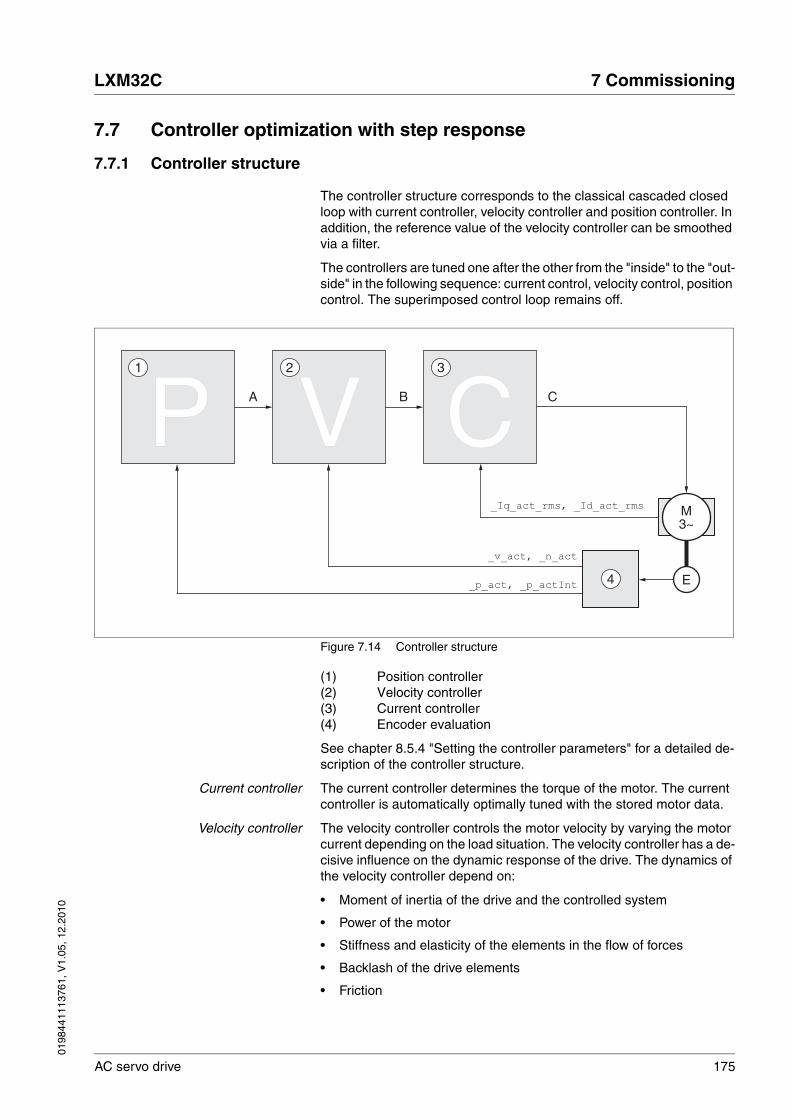
0198
4411
1376
1, V
1.05
, 12.
2010
LXM32C 7 Commissioning
AC servo drive 175
7.7 Controller optimization with step response
7.7.1 Controller structure
The controller structure corresponds to the classical cascaded closed loop with current controller, velocity controller and position controller. In addition, the reference value of the velocity controller can be smoothed via a filter.
The controllers are tuned one after the other from the "inside" to the "out-side" in the following sequence: current control, velocity control, position control. The superimposed control loop remains off.
Figure 7.14 Controller structure
(1) Position controller(2) Velocity controller(3) Current controller(4) Encoder evaluation
See chapter 8.5.4 "Setting the controller parameters" for a detailed de-scription of the controller structure.
Current controller The current controller determines the torque of the motor. The current controller is automatically optimally tuned with the stored motor data.
Velocity controller The velocity controller controls the motor velocity by varying the motor current depending on the load situation. The velocity controller has a de-cisive influence on the dynamic response of the drive. The dynamics of the velocity controller depend on:
• Moment of inertia of the drive and the controlled system
• Power of the motor
• Stiffness and elasticity of the elements in the flow of forces
• Backlash of the drive elements
• Friction
M3~
E
_v_act, _n_act
_p_act, _p_actInt
A B C
4
321
_Iq_act_rms, _Id_act_rms
P V C

176 AC servo drive
7 Commissioning LXM32C
0198
4411
1376
1, V
1.05
, 12.
2010
Position controller The position controller reduces the difference between the reference po-sition and the actual position of the motor (position deviation) to a mini-mum. When the motor is at a standstill, the position deviation is close to zero in the case of a well-tuned position controller.
An optimized velocity control loop is a prerequisite for good amplification of the position controller.
7.7.2 Optimization
The drive optimization function matches the device to the application conditions. The following options are available:
• Selecting control loops. Superimposed control loops are automati-cally deactivated.
• Defining reference value signals: signal type, amplitude, frequency and starting point
• Testing control performance with the signal generator.
• Recording the control performance on screen and evaluating it with the commissioning software.
Setting reference value signals � Start controller optimization with the commissioning software.
� Set the following values for the reference value signal:
• Signal type: Step "positive"
• Amplitude: 100 1/min
• Cycle duration: 100 ms
• Number of repetitions: 1
� Start recording
Only the signal types "Step" and "Square" allow you to determine the entire dynamic behavior of a control loop. The manual shows signal paths for the signal type "Step".
Entering controller values The optimization steps described on the following pages require you to enter control loop parameters and test their effect by triggering a step function.
A step function is triggered as soon as you start recording in the com-missioning software.
You can enter controller values for optimization in the parameters win-dow in the "Control" group.
Controller parameter sets This device allows you to use two controller parameter sets. It is possible to switch form one set of controller parameters to the other during oper-ation. The active controller parameter set is selected with the parameter CTRL_SelParSet.
The corresponding parameters are CTRL1_xx for the first controller pa-rameter set and CTRL2_xx for the second controller parameter set. The following descriptions use the notation CTRL1_xx (CTRL2_xx) if there are no functional differences between the two controller parameter sets.

0198
4411
1376
1, V
1.05
, 12.
2010
LXM32C 7 Commissioning
AC servo drive 177
7.7.3 Optimizing the velocity controller
Optimum settings of complex mechanical control systems require hands-on experience with controller tuning . This includes the ability to calculate control loop parameters and to apply identification procedures.
Less complex mechanical systems can often be successfully optimized by means of experimental adjustment using the aperiodic limit method. The following parameters are used for this:
Check and optimize the calculated values in a second step, as described on page 182.
Parameter nameHMI menuHMI name
Description UnitMinimum valueFactory settingMaximum value
Data typeR/WPersistentExpert
Parameter address via fieldbus
CTRL1_KPn
ConF → drC-
Pn1
Velocity controller P gain
The default value is calculated on the basis of the motor parameters.
This parameter is switched gradually over the time defined in CTRL_ParChgTime.
In increments of 0.0001 A/min-1.
Changed settings become active immedi-ately.
A/min-1
0.0001-1.2700
UINT16R/Wper.-
Modbus 4610
CTRL2_KPn
ConF → drC-
Pn2
Velocity controller P gain
The default value is calculated on the basis of the motor parameters.
This parameter is switched gradually over the time defined in CTRL_ParChgTime.
In increments of 0.0001 A/min-1.
Changed settings become active immedi-ately.
A/min-1
0.0001-1.2700
UINT16R/Wper.-
Modbus 4866
CTRL1_TNn
ConF → drC-
tin1
Velocity controller integral action time
The default value is calculated on the basis of CTRL_TAUiref.
This parameter is switched gradually over the time defined in CTRL_ParChgTime.
In increments of 0.01 ms.
Changed settings become active immedi-ately.
ms0.00-327.67
UINT16R/Wper.-
Modbus 4612
CTRL2_TNn
ConF → drC-
tin2
Velocity controller integral action time
The default value is calculated on the basis of CTRL_TAUiref.
This parameter is switched gradually over the time defined in CTRL_ParChgTime.
In increments of 0.01 ms.
Changed settings become active immedi-ately.
ms0.00-327.67
UINT16R/Wper.-
Modbus 4868
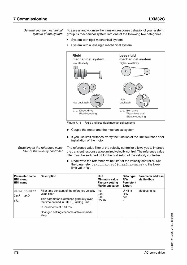
178 AC servo drive
7 Commissioning LXM32C
0198
4411
1376
1, V
1.05
, 12.
2010
Determining the mechanicalsystem of the system
To assess and optimize the transient response behavior of your system, group its mechanical system into one of the following two categories.
• System with rigid mechanical system
• System with a less rigid mechanical system
Figure 7.15 Rigid and less rigid mechanical systems
� Couple the motor and the mechanical system
� If you use limit switches: verify the function of the limit switches after installation of the motor.
Switching of the reference valuefilter of the velocity controller
The reference value filter of the velocity controller allows you to improve the transient response at optimized velocity control. The reference value filter must be switched off for the first setup of the velocity controller.
� Deactivate the reference value filter of the velocity controller. Set the parameter CTRL1_TAUnref (CTRL2_TAUnref) to the lower limit value "0".
Rigid mechanical system
Less rigid mechanical system
e. g.
low elasticity higher elasticity
low backlashhigh backlash
Elastic coupling
Belt drivee. g. Direct driveRigid coupling Weak drive shaft
Parameter nameHMI menuHMI name
Description UnitMinimum valueFactory settingMaximum value
Data typeR/WPersistentExpert
Parameter address via fieldbus
CTRL1_TAUnref
ConF → drC-
tAu1
Filter time constant of the reference velocity value filter
This parameter is switched gradually over the time defined in CTRL_ParChgTime.
In increments of 0.01 ms.
Changed settings become active immedi-ately.
ms0.009.00327.67
UINT16R/Wper.-
Modbus 4616

0198
4411
1376
1, V
1.05
, 12.
2010
LXM32C 7 Commissioning
AC servo drive 179
NOTE: The procedure for optimization of the settings is only a sugges-tion. It is the responsibility of the user to decide whether the method is suitable for the actual application.
Determining controller parametervalues for rigid mechanical systems
In the case of a rigid mechanical system, adjusting the control perform-ance on the basis of the table is possible if:
• the moment of inertia of the load and of the motor are known and
• the moment of inertia of the load and of the motor are constant
The P gain CTRL_KPn and the integral action time CTRL_TNn depend on:
• JL: moment of inertia of the load
• JM: moment of inertia of the motor
� Determine the controller parameter values using Table 7.1:
Table 7.1 Determining controller values
Determining controller parametervalues for rigid mechanical systems
For optimization purposes, determine the P gain of the velocity control-ler at which the controller adjusts velocity _v_act as quickly as possible without overshooting.
� Set the integral action time CTRL1_TNn (CTRL2_TNn) to infinite (= 327.67 ms).
If a load torque acts on the motor when the motor is at a standstill, the integral action time must not exceed a value that causes uncontrolled change of the motor position.
If the motor is subject to loads when it is at a standstill, setting the integral action time to "infinite" may cause position deviations. Reduce the integral action time if the deviation is unacceptable in your application. However, reducing the integral action time can adversely affect optimization results.
CTRL2_TAUnref
ConF → drC-
tAu2
Filter time constant of the reference velocity value filter
This parameter is switched gradually over the time defined in CTRL_ParChgTime.
In increments of 0.01 ms.
Changed settings become active immedi-ately.
ms0.009.00327.67
UINT16R/Wper.-
Modbus 4872
Parameter nameHMI menuHMI name
Description UnitMinimum valueFactory settingMaximum value
Data typeR/WPersistentExpert
Parameter address via fieldbus
JL= JM JL= 5 * JM JL= 10 * JM
JL[kgcm2] KPn TNn KPn TNn KPn TNn
1 0.0125 8 0.008 12 0.007 16
2 0.0250 8 0.015 12 0.014 16
5 0.0625 8 0.038 12 0.034 16
10 0.125 8 0.075 12 0.069 16
20 0.25 8 0.15 12 0.138 16
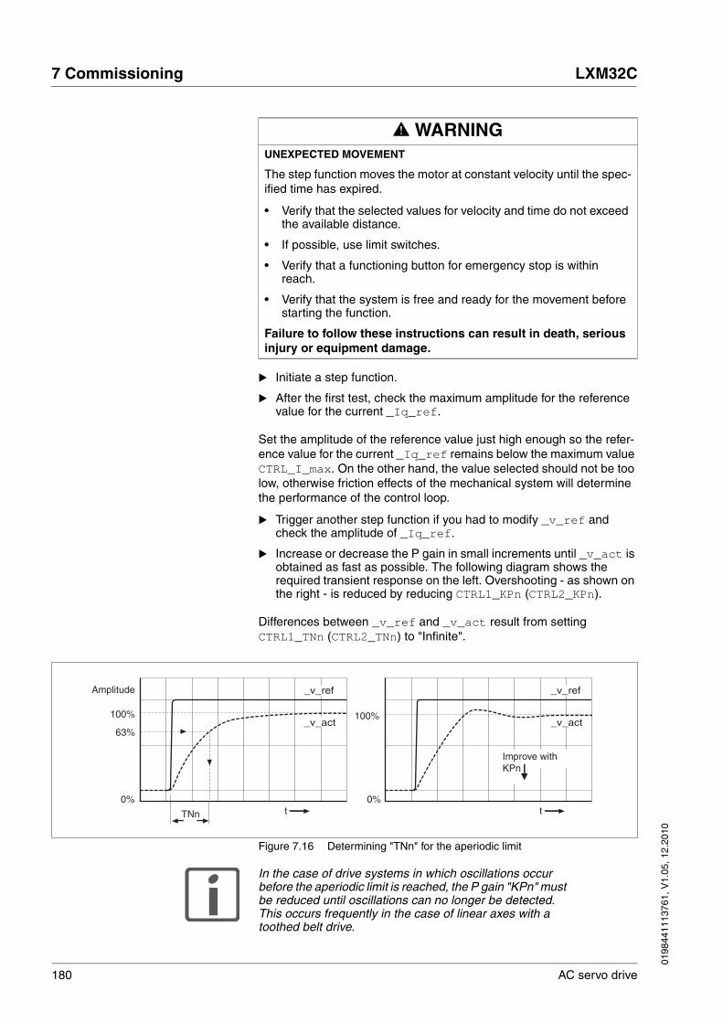
180 AC servo drive
7 Commissioning LXM32C
0198
4411
1376
1, V
1.05
, 12.
2010
� Initiate a step function.
� After the first test, check the maximum amplitude for the reference value for the current _Iq_ref.
Set the amplitude of the reference value just high enough so the refer-ence value for the current _Iq_ref remains below the maximum value CTRL_I_max. On the other hand, the value selected should not be too low, otherwise friction effects of the mechanical system will determine the performance of the control loop.
� Trigger another step function if you had to modify _v_ref and check the amplitude of _Iq_ref.
� Increase or decrease the P gain in small increments until _v_act is obtained as fast as possible. The following diagram shows the required transient response on the left. Overshooting - as shown on the right - is reduced by reducing CTRL1_KPn (CTRL2_KPn).
Differences between _v_ref and _v_act result from setting CTRL1_TNn (CTRL2_TNn) to "Infinite".
Figure 7.16 Determining "TNn" for the aperiodic limit
In the case of drive systems in which oscillations occur before the aperiodic limit is reached, the P gain "KPn" must be reduced until oscillations can no longer be detected. This occurs frequently in the case of linear axes with a toothed belt drive.
@ WARNINGUNEXPECTED MOVEMENT
The step function moves the motor at constant velocity until the spec-ified time has expired.
• Verify that the selected values for velocity and time do not exceed the available distance.
• If possible, use limit switches.
• Verify that a functioning button for emergency stop is within reach.
• Verify that the system is free and ready for the movement before starting the function.
Failure to follow these instructions can result in death, serious injury or equipment damage.
0%tt
_v_act
_v_ref
100%
63%
0%
100%
TNn
_v_act
_v_ref
KPn
Amplitude
Improve with
0198
4411
1376
1, V
1.05
, 12.
2010
LXM32C 7 Commissioning
AC servo drive 181
Graphic determination of the 63%value
Graphically determine the point at which the actual velocity _v_act reaches 63% of the final value. The integral action time CTRL1_TNn (CTRL2_TNn) then results as a value on the time axis. The commission-ing software supports you with the evaluation:
Parameter nameHMI menuHMI name
Description UnitMinimum valueFactory settingMaximum value
Data typeR/WPersistentExpert
Parameter address via fieldbus
CTRL1_TAUiref Filter time constant of the reference current value filter
This parameter is switched gradually over the time defined in CTRL_ParChgTime.
In increments of 0.01 ms.
Changed settings become active immedi-ately.
ms0.000.504.00
UINT16R/Wper.-
Modbus 4618
CTRL2_TAUiref Filter time constant of the reference current value filter
This parameter is switched gradually over the time defined in CTRL_ParChgTime.
In increments of 0.01 ms.
Changed settings become active immedi-ately.
ms0.000.504.00
UINT16R/Wper.-
Modbus 4874

182 AC servo drive
7 Commissioning LXM32C
0198
4411
1376
1, V
1.05
, 12.
2010
7.7.4 Checking and optimizing default settings
Figure 7.17 Step responses with good control performance
The controller is properly set when the step response is approximately identical to the signal shown. Good control performance is characterized by
• Fast transient response
• Overshooting up to a maximum of 40%, 20% is recommended.
If the control performance does not correspond to the curve shown, change CTRL_KPn in increments of about 10% and then trigger another step function:
• If the control is too slow: Use a higher CTRL1_KPn (CTRL2_KPn) value.
• If the control tends to oscillate: Use a lower CTRL1_KPn (CTRL2_KPn) value.
Oscillation ringing is characterized by continuous acceleration and de-celeration of the motor.
Figure 7.18 Optimizing insufficient velocity controller settings
If the controller performance remains unsatisfactory in spite of optimization, contact your local sales representative.
0%tt
100%
0%
100%
_v_act
_v_ref
_v_act
_v_ref
Am
plitu
de
Am
plitu
de
Rigid mechanicalsystem
Less rigid mechanical system
0%tt
100%
0%
100%
_v_act
_v_ref
_v_act
_v_ref
KPn KPnImprove with Improve with
OscillationsToo slow
Am
plitu
d
Am
plitu
d
0198
4411
1376
1, V
1.05
, 12.
2010
LXM32C 7 Commissioning
AC servo drive 183
7.7.5 Optimizing the position controller
Optimization requires good control dynamics in the subordinate velocity control circuit.
When tuning the position controller, you must optimize the P gain CTRL1_KPp (CTRL2_KPp) in two limits:
• CTRL1_KPp (CTRL2_KPp) too high: Overshooting of the mechani-cal system, instability of the closed-loop control
• CTRL1_KPp (CTRL2_KPp) too low: High position deviation
Parameter nameHMI menuHMI name
Description UnitMinimum valueFactory settingMaximum value
Data typeR/WPersistentExpert
Parameter address via fieldbus
CTRL1_KPp
ConF → drC-
PP1
Position controller P gain
The default value is calculated.
This parameter is switched gradually over the time defined in CTRL_ParChgTime.
In increments of 0.1 1/s.
Changed settings become active immedi-ately.
1/s2.0-900.0
UINT16R/Wper.-
Modbus 4614
CTRL2_KPp
ConF → drC-
PP2
Position controller P gain
The default value is calculated.
This parameter is switched gradually over the time defined in CTRL_ParChgTime.
In increments of 0.1 1/s.
Changed settings become active immedi-ately.
1/s2.0-900.0
UINT16R/Wper.-
Modbus 4870
@ WARNINGUNEXPECTED MOVEMENT
The step function moves the motor at constant velocity until the spec-ified time has expired.
• Verify that the selected values for velocity and time do not exceed the available distance.
• If possible, use limit switches.
• Verify that a functioning button for emergency stop is within reach.
• Verify that the system is free and ready for the movement before starting the function.
Failure to follow these instructions can result in death, serious injury or equipment damage.

184 AC servo drive
7 Commissioning LXM32C
0198
4411
1376
1, V
1.05
, 12.
2010
Setting the reference value signal � Select Position Controller as the reference value in the commission-ing software.
� Set the reference signal:
• Signal type: "Step"
• For rotary motors: Set the amplitude to approx. 1/10 motor revolu-tion.
The amplitude is entered in user-defined units. With the default scaling, the resolution is 16384 usr per motor revolution.
Selecting the recording signals � Select the values in the box General Recording Parameters:
• Reference position of position controller _p_refusr (_p_ref)
• Actual position of position controller _p_actusr (_p_act)
• Actual velocity _v_act
• Current motor current _Iq_ref
Controller values for the position controller can be changed in the same parameter group that you already used for the velocity controller.
Optimizing the position controllervalue
� Trigger a step function with the default controller values.
� After the first test, check the values achieved for _n_act and _Iq_ref for current and velocity control. The values must not reach the current and velocity limitation range.
Figure 7.19 Step responses of a position controller with good control perform-ance
The setting of the p gain CTRL1_KPp (CTRL2_KPp) is optimal if the ref-erence value is reached rapidly and with little or no overshooting.
If the control performance does not correspond to the curve shown, change the P gain CTRL1_KPp (CTRL2_KPp) in increments of approxi-mately 10% and trigger another step function.
• If the control tends to oscillate: Use a lower KPp value.
• If the actual value is too slow reaching the reference value: Use a higher KPp value.
p_act
p_ref
p_act
p_ref
0%tt
100%
0%
100%
Am
plitu
de
Am
plitu
de
Rigid mechanicalsystem
Less rigid mechanical system

0198
4411
1376
1, V
1.05
, 12.
2010
LXM32C 7 Commissioning
AC servo drive 185
Figure 7.20 Optimizing inadequate position controller settings
7.8 Memory Card
The devices features a slot for a memory card. The parameters stored on the memory card can be transferred to other devices. If a device is re-placed, a new device of the same type can be operated with identical pa-rameters.
NOTE: The contents of the memory card is only compared to the param-eters stored in the device when the device is switched on.
If the parameters on the memory card and in the device are identical, the 7-segment display briefly shows Card during start-up.
Figure 7.21 Slot for memory card
Note the following:
• Use only genuine accessory memory cards.
• Do not touch the gold contacts.
• The insert/remove cycles of the memory card are limited.
• The memory card can remain in the device.
0%t
Am
plitu
de
Am
plitu
de
t
Improve
with KPpImprove
with KPp
Control oscillatingControl too slow
p_act p_act
p_refp_ref
100%
0%
100%
Mem
ory
Car
d

186 AC servo drive
7 Commissioning LXM32C
0198
4411
1376
1, V
1.05
, 12.
2010
Inserting a memory card � The controller supply voltage is switched off.
� Insert the memory card into the device with the gold contacts face down; the slanted corner must be face to the mounting plate.
� Switch on the controller supply voltage.
Observe the 7-segment display during the initialization of the device:
Card is displayed
Card is displayed for a short period of time during initialization of the device.
Memory card detected, no user inter-vention required. The parameter values stored in the device and the contents of the mem-ory card are identical.
Card is displayed permanently. Memory card detected, user interven-tion required.See chapter 7.8.1 "Data exchange with the memory card", page 187. The parameter values stored in the device and the contents of the memory card are different or the memory card has been removed.
Card is not displayed. No memory card detected.Switch off the controller supply volt-age. Verify that the memory card has been properly inserted (contacts, slanted corner).

0198
4411
1376
1, V
1.05
, 12.
2010
LXM32C 7 Commissioning
AC servo drive 187
7.8.1 Data exchange with the memory card
If there are differences between the parameters on the memory card and the parameters stored in the device, the device stops after initiali-zation and displays CARD.
Copying data or ignoring thememory card (Cardignr, ctod,
dtoc)
� The 7-segment display shows Card.
� Press the navigation button.
� The 7-segment display shows the last setting, for example ignr.
� Briefly press the navigation button to activate the Edit mode.
� The 7-segment display continues to display the last setting, the Edit LED lights.
� Select one of the following using the navigation button1:
• ignr ignores the memory card.
• ctod transfers the data from the memory card to the device.
• dtoc transfers the data from the device to the memory card.
� The device switches to operating state 4 Ready To Switch On.
Figure 7.22 Memory card via integrated HMI
(1) Data on the memory card and in the device are different: The device displays card and waits for user intervention.
(2) Transition to operating state 4 Ready To Switch On (memory card is ignored).
(3) Transfer of data (ctod = card to device, dtoc = device to card) and transition to operating state 4 Ready To Switch On.
1. Options may be limited
Fault Edit Value UnitOp
Mon
Conf
Fault Edit Value UnitOp
Mon
Conf
Fault Edit Value UnitOp
Mon
Conf
ESC
ESC
1
2
Fault Edit Value UnitOp
Mon
Conf
32
Fault Edit Value UnitOp
Mon
Conf
Fault Edit Value UnitOp
Mon
Conf
Fault Edit Value UnitOp
Mon
Conf
188 AC servo drive
7 Commissioning LXM32C
0198
4411
1376
1, V
1.05
, 12.
2010
Memory card has been removed(CARDmiss)
If you removed the memory card, the device displays CARD after initiali-zation. If you confirm this, the display shows miss. After you have con-firmed this warning, the product switches to the operating state 4 Ready To Switch On..
Write protection for memory card(CARD, ENPR, dipr, prot)
It is possible to write-protect the memory card for LXM 32 (prot). For ex-ample, you may want to write-protect memory cards used for regular du-plication of device data.
To write-protect the memory card, select CONF - ACG-CARD on the HMI.
Memory cards can also be write-protected via the commissioning soft-ware.
7.9 Duplicating existing device settings
Application and advantage • Multiple devices are to have the same settings, for example, when devices are replaced.
Prerequisites Device type, motor type and device firmware must be identical.Tools for duplication:
• Memory card
• Commissioning software (for Windows)
The controller supply voltage must be switched on at the device.
Duplication using a memory card Device settings can be stored on a memory card (accessories). The stored device settings can be copied to a device of the same type. Note that the fieldbus address and the settings for the monitoring functions are copied along with this information. See chapter 7.8 "Memory Card", page 185 for additional information.
Duplication using thecommissioning software
The commissioning software installed on a PC can save the settings of a device in the form of a configuration file. The stored device settings can be copied to a device of the same type. Note that the fieldbus address and the settings for the monitoring functions are copied along with this information. See the manual for the commissioning software or the on-line help for additional information.
Selection Meaning
ENPR Write protection on (prot)
dipr Write protection off
0198
4411
1376
1, V
1.05
, 12.
2010
LXM32C 8 Operation
AC servo drive 189
88 Operation
The chapter "Operation" describes the basic operating states, operating modes and functions of the device.
Access channels
Operating states
Operating modes
@ WARNINGUNINTENDED BEHAVIOR
The behavior of the drive system is governed by numerous stored data or settings. Unsuitable settings or data may trigger unexpected movements or responses to signals and disable monitoring functions.
• Do NOT operate the drive system with unknown settings or data.
• Verify that the stored data and settings are correct.
• When commissioning, carefully run tests for all operating states and potential error situations.
• Verify the functions after replacing the product and also after making changes to the settings or data.
• Only start the system if there are no persons or obstructions in the hazardous area.
Failure to follow these instructions can result in death, serious injury or equipment damage.
8.1 "Access channels"
8.2 "Operating states"
8.2.1 "State diagram"
8.2.2 "State transitions"
8.2.3 "Indication of the operating state"
8.2.4 "Changing the operating state"
8.3 "Operating modes"
8.3.1 "Starting the operating mode"
8.3.2 "Changing the operating mode"
8.3.3 "Operating mode Jog"
8.3.4 "Operating mode Electronic Gear"
8.3.5 "Operating mode Profile Torque"
8.3.6 "Operating mode Profile Velocity"

190 AC servo drive
8 Operation LXM32C
0198
4411
1376
1, V
1.05
, 12.
2010
Movement range
Extended settings
Functions for target valueprocessing
Functions for monitoringmovements
Functions for monitoring internaldevice signals
8.4 "Movement range"
8.4.1 "Scaling"
8.5 "Extended settings"
8.5.1 "Setting the PTO interface"
8.5.2 "Setting the digital signal inputs and signal outputs"
8.5.3 "Setting the motion profile for the velocity"
8.5.4 "Setting the controller parameters"
8.5.5 "Settings of parameter _DCOMstatus"
8.6 "Functions for target value processing"
8.6.1 "Stop movement with Halt"
8.6.2 "Stopping a movement with Quick Stop"
8.6.3 "Inverting the analog signal inputs"
8.6.4 "Limitation of the velocity via signal inputs"
8.6.5 "Limitation of the current via signal inputs"
8.6.6 "Jerk limitation"
8.6.7 "Zero Clamp"
8.7 "Functions for monitoring movements"
8.7.1 "Limit switches"
8.7.2 "Load-dependent position deviation (following error)"
8.7.3 "Motor standstill"
8.7.4 "Position deviation window"
8.7.5 "Velocity deviation window"
8.7.6 "Velocity threshold value"
8.7.7 "Current threshold value"
8.8 "Functions for monitoring internal device signals"
8.8.1 "Temperature monitoring"
8.8.2 "Monitoring load and overload (I2T monitoring)"
8.8.3 "Commutation monitoring"
8.8.4 "Monitoring of mains phases"
8.8.5 "Ground fault monitoring"
0198
4411
1376
1, V
1.05
, 12.
2010
LXM32C 8 Operation
AC servo drive 191
8.1 Access channels
The product can be addressed via different access channels. Access channels are:
• Integrated HMI
• Commissioning software
• Digital and analog Input signals
If several access channels are active at the same time, this may lead to unintended behavior. Access control can be used to limit access to a particular access channel.
The product offers 2 different possibilities of access control.
• Non-exclusive access
• Exclusive access via an access channel
When the product is switched on, there is no exclusive access via an ac-cess channel.
Only one access channel can have exclusive access to the product. An exclusive access can be provided via different access channels:
• Via the integrated HMI:
The operating mode Jog or Autotuning can be started via the HMI.
• Via the commissioning software:
The commissioning software receives exclusive access via the switch "Exclusive access" in position "On".
When the product is switched on, the reference values are effective at the analog inputs (CN6.1) and PTI interface (Pulse Train In, CN5). If ex-clusive access has been assigned to an access channel, signals at the analog inputs and the PTI interface are ignored.
The signal input functions "Halt", "Fault Reset", "Enable", "Positive Limit Switch (LIMP)", "Negative Limit Switch (LIMN)" and "Reference Switch (REF)" as well as the signals of the safety function STO (STO_A and STO_B) are effective during exclusive access.
Access to the product via the HMI (writing parameters) can be revoked by means of the parameter HMIlocked.
@ WARNINGUNINTENDED BEHAVIOR CAUSED BY ACCESS CONTROL
Improper use of access control may cause commands to be triggered or blocked.
• Verify that no unintended behavior is caused as a result of ena-bling or disabling exclusive access.
• Verify that impermissible access is blocked.
• Verify that required access is available.
Failure to follow these instructions can result in death, serious injury or equipment damage.

192 AC servo drive
8 Operation LXM32C
0198
4411
1376
1, V
1.05
, 12.
2010
Parameter nameHMI menuHMI name
Description UnitMinimum valueFactory settingMaximum value
Data typeR/WPersistentExpert
Parameter address via fieldbus
AccessLock Locking other access channels
Value 0: Allow control via other access chan-nelsValue 1: Lock control via other access chan-nels
Example:The access channel is used by the fieldbus.In this case, control via the commissioning software or the HMI is not possible.
The access channel can only be locked after the current operating mode has terminated.
Changed settings become active immedi-ately.
-001
UINT16R/W--
Modbus 284
HMIlocked Lock HMI
0 / Not Locked / nLoc: HMI not locked1 / Locked / Loc: HMI locked
The following functions can no longer be started when the HMI is locked:- Parameter change- Jog- Autotuning- Fault Reset
Changed settings become active immedi-ately.
-001
UINT16R/Wper.-
Modbus 14850
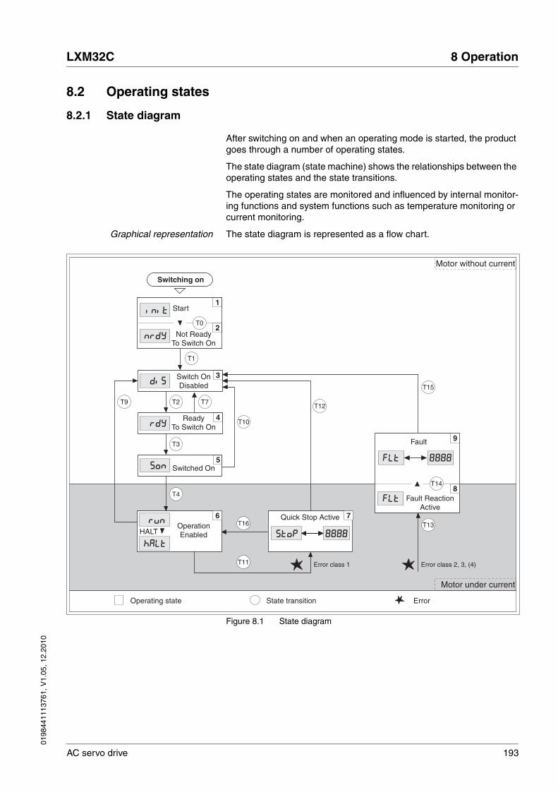
0198
4411
1376
1, V
1.05
, 12.
2010
LXM32C 8 Operation
AC servo drive 193
8.2 Operating states
8.2.1 State diagram
After switching on and when an operating mode is started, the product goes through a number of operating states.
The state diagram (state machine) shows the relationships between the operating states and the state transitions.
The operating states are monitored and influenced by internal monitor-ing functions and system functions such as temperature monitoring or current monitoring.
Graphical representation The state diagram is represented as a flow chart.
Figure 8.1 State diagram
T10
T12
T15
3
4
6
5
rdy
Son
dis
T11
T16
T4
T3
T9 T2 T7
T1
nrdy
INIT1
2T0
T13
Fault
fLt
fLt
8
9
T14
7
Stop 8888
8888
HaLt
rUnOperationEnabled
ReadyTo Switch On
Switched On
Switch OnDisabled
Not ReadyTo Switch On
Fault ReactionActive
Quick Stop Active
Switching on
Operating state State transition
Start
HALT
Motor under current
Motor without current
Error class 2, 3, (4)Error class 1
Error
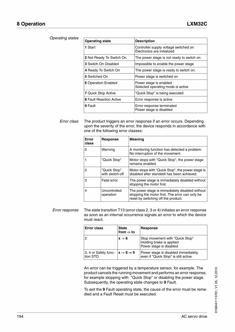
194 AC servo drive
8 Operation LXM32C
0198
4411
1376
1, V
1.05
, 12.
2010
Operating states
Error class The product triggers an error response if an error occurs. Depending upon the severity of the error, the device responds in accordance with one of the following error classes:
Error response The state transition T13 (error class 2, 3 or 4) initiates an error response as soon as an internal occurrence signals an error to which the device must react.
An error can be triggered by a temperature sensor, for example. The product cancels the running movement and performs an error response, for example stopping with "Quick Stop" or disabling the power stage. Subsequently, the operating state changes to 9 Fault.
To exit the 9 Fault operating state, the cause of the error must be reme-died and a Fault Reset must be executed.
Operating state Description
1 Start Controller supply voltage switched onElectronics are initialized
2 Not Ready To Switch On The power stage is not ready to switch on
3 Switch On Disabled Impossible to enable the power stage
4 Ready To Switch On The power stage is ready to switch on.
5 Switched On Power stage is switched on
6 Operation Enabled Power stage is enabledSelected operating mode is active
7 Quick Stop Active "Quick Stop" is being executed
8 Fault Reaction Active Error response is active
9 Fault Error response terminatedPower stage is disabled
Error class
Response Meaning
0 Warning A monitoring function has detected a problem. No interruption of the movement.
1 "Quick Stop" Motor stops with "Quick Stop", the power stage remains enabled.
2 "Quick Stop" with switch-off
Motor stops with "Quick Stop", the power stage is disabled after standstill has been achieved.
3 Fatal error The power stage is immediately disabled without stopping the motor first.
4 Uncontrolled operation
The power stage is immediately disabled without stopping the motor first. The error can only be reset by switching off the product.
Error class Statefrom -> to
Response
2 x -> 8 Stop movement with "Quick Stop"Holding brake is appliedPower stage is disabled
3, 4 or Safety func-tion STO
x -> 8 -> 9 Power stage is disabled immediately, even if "Quick Stop" is still active.
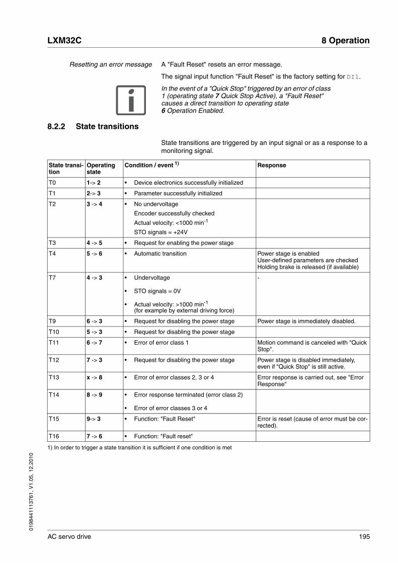
0198
4411
1376
1, V
1.05
, 12.
2010
LXM32C 8 Operation
AC servo drive 195
Resetting an error message A "Fault Reset" resets an error message.
The signal input function "Fault Reset" is the factory setting for DI1.
In the event of a "Quick Stop" triggered by an error of class 1 (operating state 7 Quick Stop Active), a "Fault Reset" causes a direct transition to operating state 6 Operation Enabled.
8.2.2 State transitions
State transitions are triggered by an input signal or as a response to a monitoring signal.
State transi-tion
Operating state
Condition / event 1) Response
T0 1-> 2 • Device electronics successfully initialized
T1 2-> 3 • Parameter successfully initialized
T2 3 -> 4 • No undervoltage
Encoder successfully checked
Actual velocity: <1000 min-1
STO signals = +24V
T3 4 -> 5 • Request for enabling the power stage
T4 5 -> 6 • Automatic transition Power stage is enabledUser-defined parameters are checkedHolding brake is released (if available)
T7 4 -> 3 • Undervoltage
• STO signals = 0V
• Actual velocity: >1000 min-1
(for example by external driving force)
-
T9 6 -> 3 • Request for disabling the power stage Power stage is immediately disabled.
T10 5 -> 3 • Request for disabling the power stage
T11 6 -> 7 • Error of error class 1 Motion command is canceled with "Quick Stop".
T12 7 -> 3 • Request for disabling the power stage Power stage is disabled immediately, even if "Quick Stop" is still active.
T13 x -> 8 • Error of error classes 2, 3 or 4 Error response is carried out, see "Error Response"
T14 8 -> 9 • Error response terminated (error class 2)
• Error of error classes 3 or 4
T15 9-> 3 • Function: "Fault Reset" Error is reset (cause of error must be cor-rected).
T16 7 -> 6 • Function: "Fault reset"
1) In order to trigger a state transition it is sufficient if one condition is met
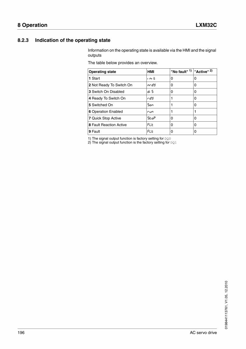
196 AC servo drive
8 Operation LXM32C
0198
4411
1376
1, V
1.05
, 12.
2010
8.2.3 Indication of the operating state
Information on the operating state is available via the HMI and the signal outputs
The table below provides an overview.
Operating state HMI "No fault" 1)
1) The signal output function is factory setting for DQ0
"Active" 2)
2) The signal output function is the factory setting for DQ1
1 Start Init 0 0
2 Not Ready To Switch On nrdy 0 0
3 Switch On Disabled dis 0 0
4 Ready To Switch On rdy 1 0
5 Switched On Son 1 0
6 Operation Enabled run 1 1
7 Quick Stop Active Stop 0 0
8 Fault Reaction Active FLt 0 0
9 Fault FLt 0 0

0198
4411
1376
1, V
1.05
, 12.
2010
LXM32C 8 Operation
AC servo drive 197
8.2.4 Changing the operating state
8.2.4.1 HMI
An error message can be reset via the HMI.
Figure 8.2 Reseting an error message
In the case of an error of error class 1, resetting the error message causes a transition from operating state 7 Quick Stop Active back to op-erating state 6 Operation Enabled.
In the case of an error of error classes 2 or 3, resetting the error mes-sage causes a transition from operating state 9 Fault back to operating state 3 Switch On Disable.
8.2.4.2 Signal inputs
It is possible to switch between operating states via the signal inputs.
Signal input function "Enable" The power stage is enabled by means of the signal input function "Ena-ble".
The signal input function "Enable" is the factory setting for DI0.
Signal input function "Fault Reset" The signal input function"Fault Reset" is used to reset an error message.
The signal input function "Fault Reset" is the factory setting for DI1.
Fault Edit Value UnitOp
Mon
Conf
Fault Edit Value UnitOp
Mon
Conf
Fault Edit Value UnitOp
Mon
Conf
Fault Edit Value UnitOp
Mon
Conf
ESC
1
ESCESC
"Enable" State transition
Rising edge Enable power stageT3
Falling edge Disable power stageT9 and T12
"Fault Reset" State transition
Rising edge Resetting an error messageT15 and T16

198 AC servo drive
8 Operation LXM32C
0198
4411
1376
1, V
1.05
, 12.
2010
8.3 Operating modes
8.3.1 Starting the operating mode
The parameter IOdefaultMode is used to set the desired operating mode.
The selected operating mode is starting by enabling the power stage.
� Set the operating mode with the parameter IOdefaultMode.
8.3.2 Changing the operating mode
The operating mode can be changed after the current operating mode has been terminated.
In addition, it is also possible to change the operating mode during a run-ning movement; however, this is only possible in certain operating modes.
Parameter nameHMI menuHMI name
Description UnitMinimum valueFactory settingMaximum value
Data typeR/WPersistentExpert
Parameter address via fieldbus
IOdefaultMode
ConF → ACG-
io-M
Operating mode
0 / None / nonE: None1 / Profile Torque / torq: Profile Torque2 / Profile Velocity / VELP: Profile Velocity3 / Electronic Gear / GEAr: Electronic Gear5 / Jog / JoG: Jog
Setting can only be changed if power stage is disabled.
Changed settings become active the next time the product is switched on.
-055
UINT16R/Wper.-
Modbus 1286

0198
4411
1376
1, V
1.05
, 12.
2010
LXM32C 8 Operation
AC servo drive 199
Changing the operating modeduring a movement
You can switch between the following operating modes during a running movement.
• Jog
• Electronic Gear
• Profile Torque
• Profile Velocity
The operating mode can be changed while the motor is at a standstill or while the motor is not at a standstill, depending on the new operating mode.
The motor is decelerated to a standstill via the ramp set in the parameter LIM_HaltReaction, see chapter 8.6.1 "Stop movement with Halt".
Changing the operating mode viasignal input
The product features the signal input function "Operating Mode Switch".
It allows you to switch via a signal input from the operating mode set in the IOdefaultMode to the operating mode set in the parameter IO_ModeSwitch.
To switch between two operating modes, you must parameterize the sig-nal input function "Operating Mode Switch", see chapter 8.5.2 "Setting the digital signal inputs and signal outputs".
Operating mode to be changed to Motor standstill
Jog With motor standstill
Electronic Gear(position synchronization)
With motor standstill
Electronic Gear(velocity synchronization)
Without motor standstill
Profile Torque Without motor standstill
Profile Velocity Without motor standstill
Parameter nameHMI menuHMI name
Description UnitMinimum valueFactory settingMaximum value
Data typeR/WPersistentExpert
Parameter address via fieldbus
IO_ModeSwitch
ConF → ACG-
ioMS
Operating mode for signal input function Operating Mode Switch
0 / None / nonE: None1 / Profile Torque / torq: Profile Torque2 / Profile Velocity / VELP: Profile Velocity3 / Electronic Gear / GEAr: Electronic Gear
Changed settings become active immedi-ately.
-003
UINT16R/Wper.-
Modbus 1630
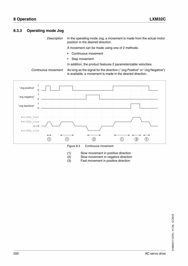
200 AC servo drive
8 Operation LXM32C
0198
4411
1376
1, V
1.05
, 12.
2010
8.3.3 Operating mode Jog
Description In the operating mode Jog, a movement is made from the actual motor position in the desired direction.
A movement can be made using one of 2 methods:
• Continuous movement
• Step movement
In addition, the product features 2 parameterizable velocities.
Continuous movement As long as the signal for the direction ( "Jog Positive" or "Jog Negative") is available, a movement is made in the desired direction.
Figure 8.3 Continuous movement
(1) Slow movement in positive direction(2) Slow movement in negative direction(3) Fast movement in positive direction
1
0
1
0
1
0
v = 0
v = JOGn_slow
v = JOGn_fast
"Jog positive"
"Jog negative"
"Jog fast/slow"
v = JOGn_slow
� � � � � �
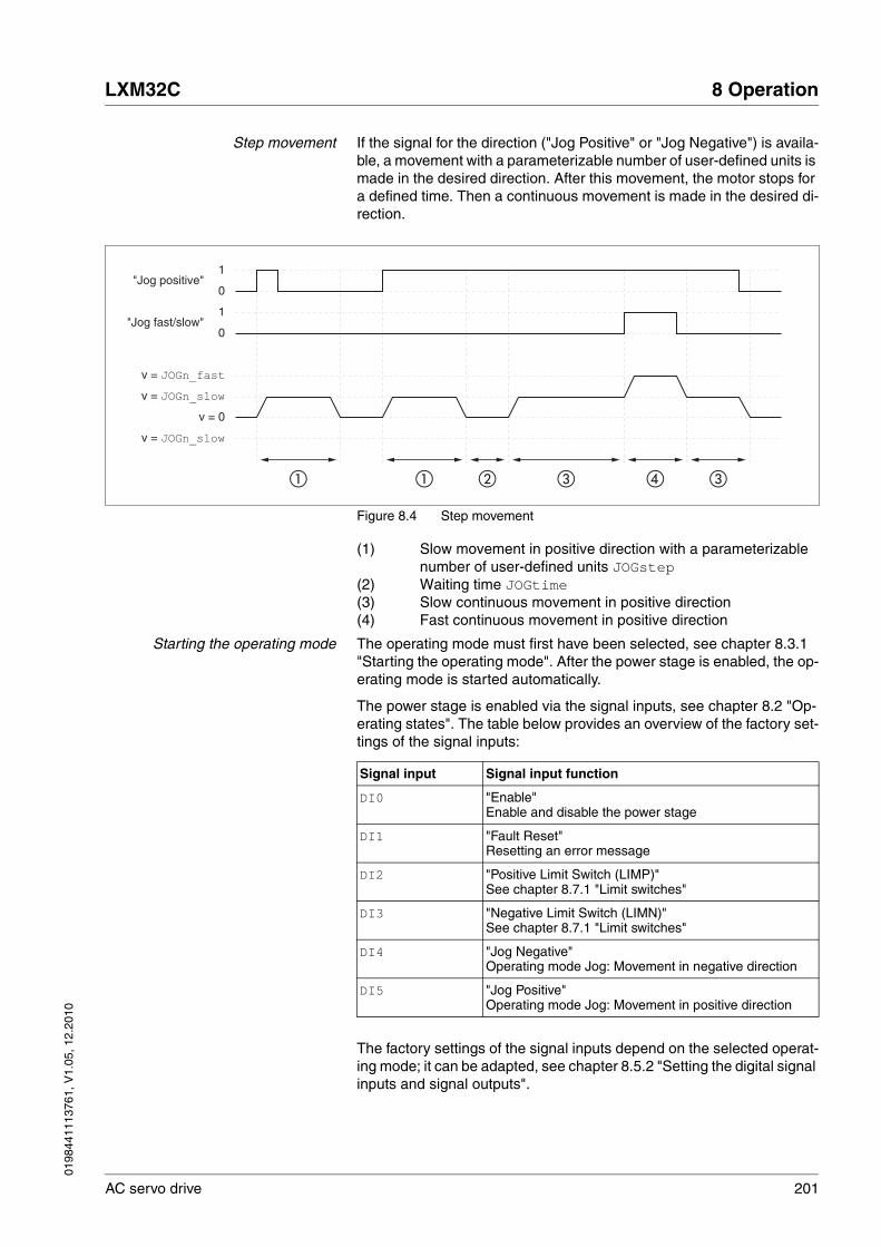
0198
4411
1376
1, V
1.05
, 12.
2010
LXM32C 8 Operation
AC servo drive 201
Step movement If the signal for the direction ("Jog Positive" or "Jog Negative") is availa-ble, a movement with a parameterizable number of user-defined units is made in the desired direction. After this movement, the motor stops for a defined time. Then a continuous movement is made in the desired di-rection.
Figure 8.4 Step movement
(1) Slow movement in positive direction with a parameterizable number of user-defined units JOGstep
(2) Waiting time JOGtime(3) Slow continuous movement in positive direction(4) Fast continuous movement in positive direction
Starting the operating mode The operating mode must first have been selected, see chapter 8.3.1 "Starting the operating mode". After the power stage is enabled, the op-erating mode is started automatically.
The power stage is enabled via the signal inputs, see chapter 8.2 "Op-erating states". The table below provides an overview of the factory set-tings of the signal inputs:
The factory settings of the signal inputs depend on the selected operat-ing mode; it can be adapted, see chapter 8.5.2 "Setting the digital signal inputs and signal outputs".
1
0
1
0
v = 0
v = JOGn_slow
v = JOGn_fast
"Jog positive"
"Jog fast/slow"
v = JOGn_slow
� � � � � �
Signal input Signal input function
DI0 "Enable"Enable and disable the power stage
DI1 "Fault Reset"Resetting an error message
DI2 "Positive Limit Switch (LIMP)"See chapter 8.7.1 "Limit switches"
DI3 "Negative Limit Switch (LIMN)"See chapter 8.7.1 "Limit switches"
DI4 "Jog Negative"Operating mode Jog: Movement in negative direction
DI5 "Jog Positive"Operating mode Jog: Movement in positive direction

202 AC servo drive
8 Operation LXM32C
0198
4411
1376
1, V
1.05
, 12.
2010
Integrated HMI It is also possible to start the operating mode via the HMI. Calling →OP→jog-→JGST enables the power stage and starts the operating mode.
The method Continuous Movement is controlled via the HMI.
Turn the navigation button to select one of 4 types of movement:
• JG- : slow movement in positive direction
• JG= : fast movement in positive direction
• -JG : slow movement in negative direction
• =JG : fast movement in negative direction
Press the navigation button to start the movement.
Terminating the operating mode The operating mode is automatically terminated by disabling the power stage.
Status messages Information on the operating state and the current movement is available via signal outputs.
The table below provides an overview of the signal outputs:
The factory settings of the signal outputs depend on the selected oper-ating mode; it can be adapted, see chapter 8.5.2 "Setting the digital sig-nal inputs and signal outputs".
Signal output Signal output function
DQ0 "No Fault"Signals the operating states 4 Ready To Switch On, 5 Switched On and 6 Operation Enabled
DQ1 "Active"Signals the operating state 6 Operation Enabled
DQ2 "In Position Deviation Window"See chapter 8.7.4 "Position deviation window"
DQ3 "Motor Standstill"See chapter 8.7.3 "Motor standstill"
DQ4 "Selected Error"See chapter 8.2.3 "Indication of the operating state"

0198
4411
1376
1, V
1.05
, 12.
2010
LXM32C 8 Operation
AC servo drive 203
8.3.3.1 Parameterization
Overview The illustration below provides an overview of the adjustable parame-ters.
Figure 8.5 Overview of adjustable parameters
Velocities 2 parameterizable velocities are available.
� Set the desired values with the parameters JOGv_slow and JOGv_fast.
Switching between velocities The product features the signal input function "Jog Fast/Slow". It allows you to switch between the two velocities via a signal input.
To switch between the two velocities, you must parameterize the signal input function "Jog Fast/Slow", see chapter 8.5.2 "Setting the digital sig-nal inputs and signal outputs".
DI4 DI0 ... DI5
"Jog negative" "Jog fast/slow"
DI5
"Jog positive"
JOGv_slow, JOGv_fast
JOGstep
JOGtime
RAMP_v_acc, RAMP_v_dec, RAMP_v_max
IO_JOGmethod
= 0 = 1
Parameter nameHMI menuHMI name
Description UnitMinimum valueFactory settingMaximum value
Data typeR/WPersistentExpert
Parameter address via fieldbus
JOGv_slow
oP → JoG-
JGLo
Velocity for slow movement
The adjustable value is internally limited to the current parameter setting in RAMP_v_max.
Changed settings become active immedi-ately.
usr_v1602147483647
UINT32R/Wper.-
Modbus 10504
JOGv_fast
oP → JoG-
JGhi
Velocity for fast movement
The adjustable value is internally limited to the current parameter setting in RAMP_v_max.
Changed settings become active immedi-ately.
usr_v11802147483647
UINT32R/Wper.-
Modbus 10506
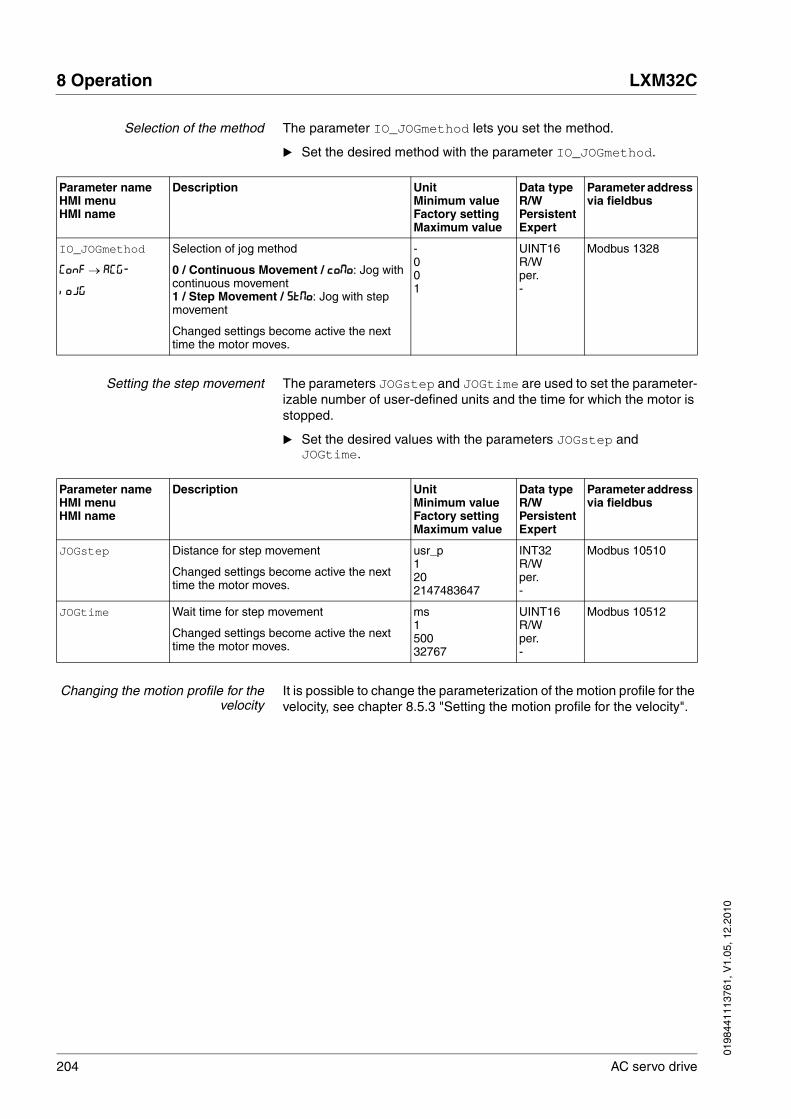
204 AC servo drive
8 Operation LXM32C
0198
4411
1376
1, V
1.05
, 12.
2010
Selection of the method The parameter IO_JOGmethod lets you set the method.
� Set the desired method with the parameter IO_JOGmethod.
Setting the step movement The parameters JOGstep and JOGtime are used to set the parameter-izable number of user-defined units and the time for which the motor is stopped.
� Set the desired values with the parameters JOGstep and JOGtime.
Changing the motion profile for thevelocity
It is possible to change the parameterization of the motion profile for the velocity, see chapter 8.5.3 "Setting the motion profile for the velocity".
Parameter nameHMI menuHMI name
Description UnitMinimum valueFactory settingMaximum value
Data typeR/WPersistentExpert
Parameter address via fieldbus
IO_JOGmethod
ConF → ACG-
ioJG
Selection of jog method
0 / Continuous Movement / coMo: Jog with continuous movement1 / Step Movement / StMo: Jog with step movement
Changed settings become active the next time the motor moves.
-001
UINT16R/Wper.-
Modbus 1328
Parameter nameHMI menuHMI name
Description UnitMinimum valueFactory settingMaximum value
Data typeR/WPersistentExpert
Parameter address via fieldbus
JOGstep Distance for step movement
Changed settings become active the next time the motor moves.
usr_p1202147483647
INT32R/Wper.-
Modbus 10510
JOGtime Wait time for step movement
Changed settings become active the next time the motor moves.
ms150032767
UINT16R/Wper.-
Modbus 10512

0198
4411
1376
1, V
1.05
, 12.
2010
LXM32C 8 Operation
AC servo drive 205
8.3.3.2 Additional settings
The following functions can be used for target value processing:
• Chapter 8.6.1 "Stop movement with Halt"
• Chapter 8.6.2 "Stopping a movement with Quick Stop"
• Chapter 8.6.4 "Limitation of the velocity via signal inputs"
• Chapter 8.6.5 "Limitation of the current via signal inputs"
• Chapter 8.6.6 "Jerk limitation"
The following functions can be used for monitoring the movement:
• Chapter 8.7.1 "Limit switches"
• Chapter 8.7.2 "Load-dependent position deviation (following error)"
• Chapter 8.7.3 "Motor standstill"
• Chapter 8.7.4 "Position deviation window"
• Chapter 8.7.5 "Velocity deviation window"
• Chapter 8.7.6 "Velocity threshold value"
• Chapter 8.7.7 "Current threshold value"

206 AC servo drive
8 Operation LXM32C
0198
4411
1376
1, V
1.05
, 12.
2010
8.3.4 Operating mode Electronic Gear
Description In the operating mode Electronic Gear, movements are carried out ac-cording to externally supplied reference value signals. A new position value is calculated on the basis of these reference value signals plus an adjustable gear ratio. The reference value signals can be A/B signals, P/D signals or CW/CCW signals.
A movement can be made using one of 3 methods:
• Position synchronization without compensation movement
In the case of position synchronization without compensation move-ment, the movement is made synchronously (position synchronicity) with the supplied reference value signals. Reference value signals supplied during an interruption caused by Halt or by an error of error class 1 are not considered.
• Position synchronization with compensation movement
In the case of position synchronization with compensation move-ment, the movement is made synchronously (position synchronicity) with the supplied reference value signals. Reference value signals supplied during an interruption caused by Halt or by an error of error class 1 are considered and compensated for.
• Velocity synchronization
In the case of velocity synchronization, the movement is made syn-chronously (velocity synchronicity) with the supplied reference value signals.
Internal units The position value for the movement depends on the internal units.
The internal units are 131072 increments per revolution.
Starting the operating mode The operating mode must first have been selected, see chapter 8.3.1 "Starting the operating mode". After the power stage is enabled, the op-erating mode is started automatically.
The power stage is enabled via the signal inputs, see chapter 8.2 "Op-erating states". The table below provides an overview of the factory set-tings of the signal inputs:
The factory settings of the signal inputs depend on the selected operat-ing mode; it can be adapted, see chapter 8.5.2 "Setting the digital signal inputs and signal outputs".
Signal input Signal input function
DI0 "Enable"Enable and disable the power stage
DI1 "Fault Reset"Resetting an error message
DI2 "Positive Limit Switch (LIMP)"See chapter 8.7.1 "Limit switches"
DI3 "Negative Limit Switch (LIMN)"See chapter 8.7.1 "Limit switches"
DI4 "Gear Ratio Switch"Switch between 2 parameterizable gear ratios
DI5 "Halt"See chapter 8.6.1 "Stop movement with Halt"
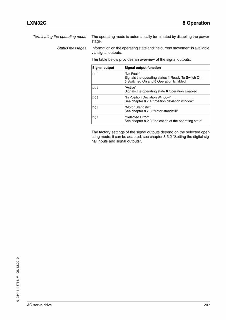
0198
4411
1376
1, V
1.05
, 12.
2010
LXM32C 8 Operation
AC servo drive 207
Terminating the operating mode The operating mode is automatically terminated by disabling the power stage.
Status messages Information on the operating state and the current movement is available via signal outputs.
The table below provides an overview of the signal outputs:
The factory settings of the signal outputs depend on the selected oper-ating mode; it can be adapted, see chapter 8.5.2 "Setting the digital sig-nal inputs and signal outputs".
Signal output Signal output function
DQ0 "No Fault"Signals the operating states 4 Ready To Switch On, 5 Switched On and 6 Operation Enabled
DQ1 "Active"Signals the operating state 6 Operation Enabled
DQ2 "In Position Deviation Window"See chapter 8.7.4 "Position deviation window"
DQ3 "Motor Standstill"See chapter 8.7.3 "Motor standstill"
DQ4 "Selected Error"See chapter 8.2.3 "Indication of the operating state"

208 AC servo drive
8 Operation LXM32C
0198
4411
1376
1, V
1.05
, 12.
2010
8.3.4.1 Parameterization
Overview The illustration below provides an overview of the adjustable parame-ters.
Figure 8.6 Overview of adjustable parameters
DI4
(DI0 ... DI5)"Gear Ratio Switch"
PTI_signaltype
GEARnum
GEARdenom
GEARnum2
GEARdenom2
GEARdir_enabl
GEARposChgMode
InvertDirOfCount
IO_GEARmethod
DI0 ... DI5"Gear Offset 1"
"Gear Offset 2"
= 0
= 1
= 1
= 3
= 2
GEARratio
= 0 = 1 ... 11
A/B P/D CW/CCW
PTI
RAMP_v_enable
= 0 = 1
RAMP_v_acc
RAMP_v_dec
RAMP_v_max
= 2
OFSp_RelPos1, OFSp_RelPos2
OFSv_target, OFS_Ramp
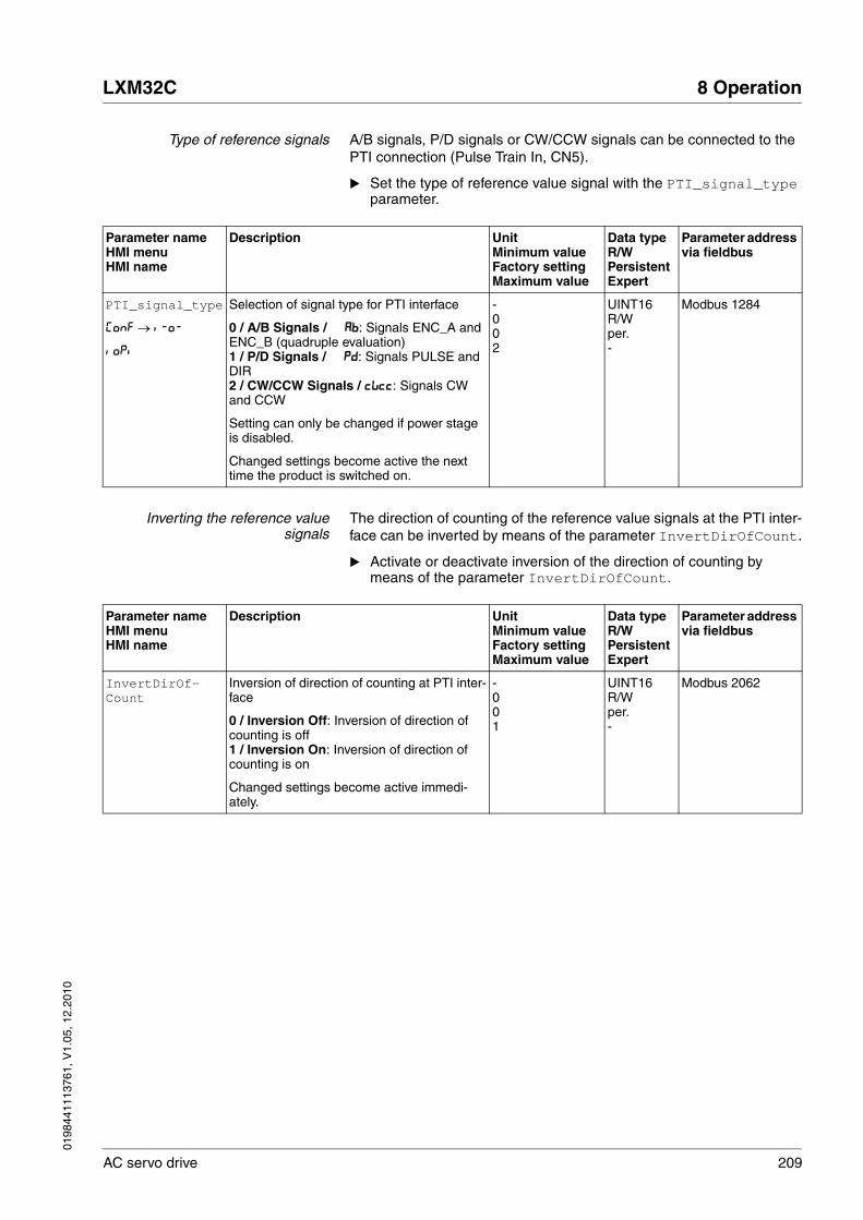
0198
4411
1376
1, V
1.05
, 12.
2010
LXM32C 8 Operation
AC servo drive 209
Type of reference signals A/B signals, P/D signals or CW/CCW signals can be connected to the PTI connection (Pulse Train In, CN5).
� Set the type of reference value signal with the PTI_signal_type parameter.
Inverting the reference valuesignals
The direction of counting of the reference value signals at the PTI inter-face can be inverted by means of the parameter InvertDirOfCount.
� Activate or deactivate inversion of the direction of counting by means of the parameter InvertDirOfCount.
Parameter nameHMI menuHMI name
Description UnitMinimum valueFactory settingMaximum value
Data typeR/WPersistentExpert
Parameter address via fieldbus
PTI_signal_type
ConF → i-o-
ioPi
Selection of signal type for PTI interface
0 / A/B Signals / Ab: Signals ENC_A and ENC_B (quadruple evaluation)1 / P/D Signals / Pd: Signals PULSE and DIR2 / CW/CCW Signals / cWcc: Signals CW and CCW
Setting can only be changed if power stage is disabled.
Changed settings become active the next time the product is switched on.
-002
UINT16R/Wper.-
Modbus 1284
Parameter nameHMI menuHMI name
Description UnitMinimum valueFactory settingMaximum value
Data typeR/WPersistentExpert
Parameter address via fieldbus
InvertDirOf-Count
Inversion of direction of counting at PTI inter-face
0 / Inversion Off: Inversion of direction of counting is off1 / Inversion On: Inversion of direction of counting is on
Changed settings become active immedi-ately.
-001
UINT16R/Wper.-
Modbus 2062

210 AC servo drive
8 Operation LXM32C
0198
4411
1376
1, V
1.05
, 12.
2010
Gear ratio The gear ratio is the ratio of the number of motor increments and the number of externally supplied reference increments.
The signal input function "Gear Ratio Switch" allows you to switch be-tween 2 parameterizable gear ratios during operation.
The parameter GEARratio allows you to set a predefined gear ratio. It is also possible to set a parameterizable gear ratio.
The parameterizable gear ratio is defined with the parameters GEARnum and GEARdenom. A negative numerator value reverses the motor's di-rection of movement.
� Set the desired gear ratio with the parameters GEARratio, GEARnum, GEARdenom, GEARnum2 and GEARdenom2.
Gear factor = =Reference increments
Motor increments Gear factor numerator
Gear factor denominator
Parameter nameHMI menuHMI name
Description UnitMinimum valueFactory settingMaximum value
Data typeR/WPersistentExpert
Parameter address via fieldbus
GEARratio
ConF → i-o-
GFAC
Selection of special gear ratios
0 / Gear Factor / FAct: Usage of gear ratio adjusted with GEARnum/GEARdenom1 / 200 / 200: 2002 / 400 / 400: 4003 / 500 / 500: 5004 / 1000 / 1000: 10005 / 2000 / 2000: 20006 / 4000 / 4000: 40007 / 5000 / 5000: 50008 / 10000 / 10.00: 100009 / 4096 / 4096: 409610 / 8192 / 8192: 819211 / 16384 / 16.38: 16384
A change of the reference value by the spec-ified value causes one motor revolution.
Changed settings become active immedi-ately.
-0011
UINT16R/Wper.-
Modbus 9740
GEARnum Numerator of gear ratio
GEARnum---------------------- = Gear ratioGEARdenom
The new gear ratio is applied when the numerator value is supplied.
Changed settings become active immedi-ately.
--214748364812147483647
INT32R/Wper.-
Modbus 9736
GEARdenom Denominator of gear ratio
See description GEARnum
-112147483647
INT32R/Wper.-
Modbus 9734
0198
4411
1376
1, V
1.05
, 12.
2010
LXM32C 8 Operation
AC servo drive 211
Selection of the method The methods specifies the way the movement is to be performed.
� Set the desired method with the parameter IO_GEARmethod.
Position change with power stagedisabled
If the method "Synchronization With Compensation Movement" is se-lected, the parameter GEARposChgMode determines the way changes to the motor position and to the reference value signals are handled with disabled power stage.
Position changes can be ignored or taken into account during a transi-tion to operating state 6 Operation Enabled.
• Off: Position changes with disabled power stage are ignored.
• On: Position changes with disabled power stage are taken into account.
Position changes between starting the operating mode and the sub-sequent enabling of the power stage are not taken into account.
GEARnum2 Numerator of gear ratio number 2
GEARnum2---------------------- = Gear ratioGEARdenom2
The new gear ratio is applied when the numerator value is supplied.
Changed settings become active immedi-ately.
--214748364812147483647
INT32R/Wper.-
Modbus 9754
GEARdenom2 Denominator of gear ratio number 2
See description GEARnum
-112147483647
INT32R/Wper.-
Modbus 9752
Parameter nameHMI menuHMI name
Description UnitMinimum valueFactory settingMaximum value
Data typeR/WPersistentExpert
Parameter address via fieldbus
Parameter nameHMI menuHMI name
Description UnitMinimum valueFactory settingMaximum value
Data typeR/WPersistentExpert
Parameter address via fieldbus
IO_GEARmethod
ConF → ACG-
ioGM
Processing mode for operating mode Elec-tronic Gear
1 / Position Synchronization Immediate / PoiM: Position synchronization without com-pensation movement2 / Position Synchronization Compen-sated / Poco: Position synchronization with compensation movement3 / Velocity Synchronization / VELo: Veloc-ity synchronization
Changed settings become active the next time the motor moves.
-113
UINT16R/Wper.-
Modbus 1326
212 AC servo drive
8 Operation LXM32C
0198
4411
1376
1, V
1.05
, 12.
2010
Offset movement The offset movement allows you to perform a movement with a param-eterizable number of increments.
Offset movements are only available for the methods "Position Synchro-nization Without Compensation Movement" and "Position Synchroniza-tion With Compensation Movement".
2 parameterizable offset positions are available. The parameters OFSp_RelPos1 and OFSp_RelPos2 are used to set the offset posi-tions.
An offset movement is started via a signal input.
To start offset movements via the signal input, you must first parameter-ize the signal input functions "Gear Offset 1" and "Gear Offset 2", see chapter 8.5.2 "Setting the digital signal inputs and signal outputs".
The velocity and the acceleration for the offset movement are set via the parameters OFSv_target and OFS_Ramp.
Parameter nameHMI menuHMI name
Description UnitMinimum valueFactory settingMaximum value
Data typeR/WPersistentExpert
Parameter address via fieldbus
GEARposChgMode Consideration of position changes with inac-tive power stage
0 / Off: Position changes in states with inac-tive power stage are discarded.1 / On: Position changes in states with inac-tive power stage are considered.
This setting has an effect only if gear processing is started in the mode 'Synchro-nization with compensation movement'.
Changed settings become active the next time the power stage is enabled.
-001
UINT16R/Wper.-
Modbus 9750
Parameter nameHMI menuHMI name
Description UnitMinimum valueFactory settingMaximum value
Data typeR/WPersistentExpert
Parameter address via fieldbus
OFSp_RelPos1 Relative offset position 1 for offset move-ment
Changed settings become active immedi-ately.
Inc-214748364802147483647
INT32R/Wper.-
Modbus 10000
OFSp_RelPos2 Relative offset position 2 for offset move-ment
Changed settings become active immedi-ately.
Inc-214748364802147483647
INT32R/Wper.-
Modbus 10004
OFSv_target Target velocity for offset movement
The maximum possible value is 5000 if the user-defined scaling factor of the velocity scaling is 1.
This applies to all user-defined scaling fac-tors. Example: If the user-defined scaling factor of the velocity scaling is 2 (ScaleVEL-num = 2, ScaleVELdenom = 1), the maxi-mum possible value is 2500.
Changed settings become active immedi-ately.
usr_v1602147483647
UINT32R/Wper.-
Modbus 9992

0198
4411
1376
1, V
1.05
, 12.
2010
LXM32C 8 Operation
AC servo drive 213
Changing the motion profile for thevelocity
If the method "Velocity Synchronization" is selected, the motion profile for the velocity can be changed.
It is possible to change the parameterization of the motion profile for the velocity, see chapter 8.5.3 "Setting the motion profile for the velocity".
Release of direction Release of direction allows you to limit movements to positive or nega-tive direction. Release of direction is set with the parameter GEARdir_enabl.
� Set the desired directions of movement with the parameter GEARdir_enabl.
OFS_Ramp Acceleration and deceleration for offset movement
Setting can only be changed if power stage is disabled.
Changed settings become active the next time the power stage is enabled.
usr_a16002147483647
UINT32R/Wper.-
Modbus 9996
Parameter nameHMI menuHMI name
Description UnitMinimum valueFactory settingMaximum value
Data typeR/WPersistentExpert
Parameter address via fieldbus
Parameter nameHMI menuHMI name
Description UnitMinimum valueFactory settingMaximum value
Data typeR/WPersistentExpert
Parameter address via fieldbus
GEARdir_enabl Enabled movement direction of gear processing
1 / Positive: Positive direction2 / Negative: Negative direction3 / Both: Both directions
This allows you to activate a return move-ment lock function.
Changed settings become active immedi-ately.
-133
UINT16R/Wper.-
Modbus 9738

214 AC servo drive
8 Operation LXM32C
0198
4411
1376
1, V
1.05
, 12.
2010
8.3.4.2 Additional settings
The following functions can be used for target value processing:
• Chapter 8.6.1 "Stop movement with Halt"
• Chapter 8.6.2 "Stopping a movement with Quick Stop"
• Chapter 8.6.4 "Limitation of the velocity via signal inputs"
• Chapter 8.6.5 "Limitation of the current via signal inputs"
• Chapter 8.6.6 "Jerk limitation"
This function is only available for the methods "Position Synchroni-zation Without Compensation Movement" and "Position Synchroni-zation With Compensation Movement".
• Chapter 8.6.7 "Zero Clamp"
This function is only available with the method "Velocity Synchroni-zation".
The following functions can be used for monitoring the movement:
• Chapter 8.7.1 "Limit switches"
• Chapter 8.7.2 "Load-dependent position deviation (following error)"
This function is only available for the methods "Position Synchroni-zation Without Compensation Movement" and "Position Synchroni-zation With Compensation Movement".
• Chapter 8.7.3 "Motor standstill"
• Chapter 8.7.4 "Position deviation window"
This function is only available for the methods "Position Synchroni-zation Without Compensation Movement" and "Position Synchroni-zation With Compensation Movement".
• Chapter 8.7.5 "Velocity deviation window"
This function is only available with the method "Velocity Synchroni-zation".
• Chapter 8.7.6 "Velocity threshold value"
• Chapter 8.7.7 "Current threshold value"
0198
4411
1376
1, V
1.05
, 12.
2010
LXM32C 8 Operation
AC servo drive 215
8.3.5 Operating mode Profile Torque
Description In the operating mode Profile Torque, a movement is made with a de-sired target torque.
Starting the operating mode The operating mode must first have been selected, see chapter 8.3.1 "Starting the operating mode". After the power stage is enabled, the op-erating mode is started automatically.
The power stage is enabled via the signal inputs, see chapter 8.2 "Op-erating states". The table below provides an overview of the factory set-tings of the signal inputs:
The factory settings of the signal inputs depend on the selected operat-ing mode; it can be adapted, see chapter 8.5.2 "Setting the digital signal inputs and signal outputs".
Terminating the operating mode The operating mode is automatically terminated by disabling the power stage.
@ WARNINGEXCESSIVELY HIGH VELOCITY DUE TO INCORRECT LIMIT VALUE
Without a proper limit value, the motor can reach a very high velocity in this operating mode.
• Check the parameterized velocity limitation.
Failure to follow these instructions can result in death, serious injury or equipment damage.
Signal input Signal input function
DI0 "Enable"Enable and disable the power stage
DI1 "Fault Reset"Resetting an error message
DI2 "Operating Mode Switch"See chapter 8.3.2 "Changing the operating mode"
DI3 "Velocity Limitation"See chapter 8.6.4 "Limitation of the velocity via signal inputs"
DI4 "Current Limitation"See chapter 8.6.5 "Limitation of the current via signal inputs"
DI5 "Halt"See chapter 8.6.1 "Stop movement with Halt"

216 AC servo drive
8 Operation LXM32C
0198
4411
1376
1, V
1.05
, 12.
2010
Status messages Information on the operating state and the current movement is available via signal outputs.
The table below provides an overview of the signal outputs:
The factory settings of the signal outputs depend on the selected oper-ating mode; it can be adapted, see chapter 8.5.2 "Setting the digital sig-nal inputs and signal outputs".
Signal output Signal output function
DQ0 "No Fault"Signals the operating states 4 Ready To Switch On, 5 Switched On and 6 Operation Enabled
DQ1 "Active"Signals the operating state 6 Operation Enabled
DQ2 "Current Threshold Reached"See chapter 8.7.7 "Current threshold value"
DQ3 "Motor Standstill"See chapter 8.7.3 "Motor standstill"
DQ4 "Selected Error"See chapter 8.2.3 "Indication of the operating state"
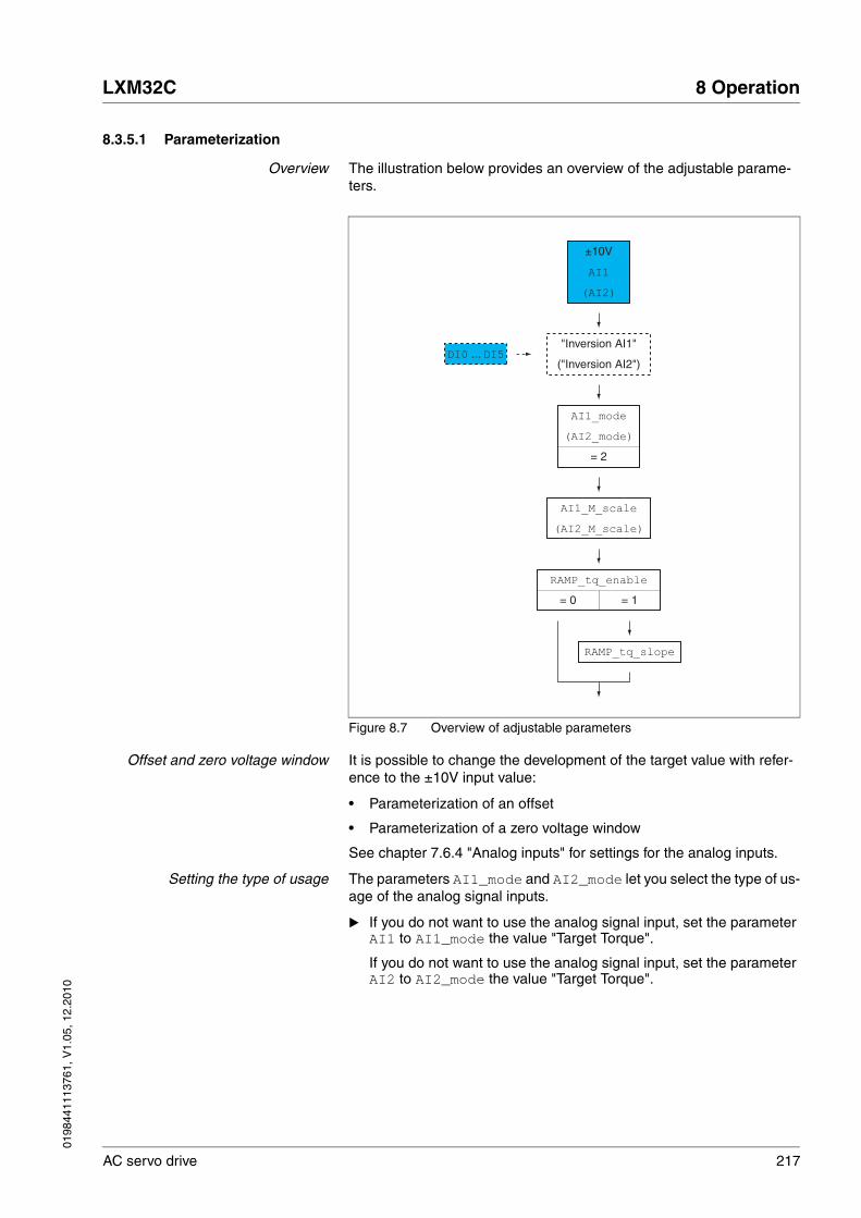
0198
4411
1376
1, V
1.05
, 12.
2010
LXM32C 8 Operation
AC servo drive 217
8.3.5.1 Parameterization
Overview The illustration below provides an overview of the adjustable parame-ters.
Figure 8.7 Overview of adjustable parameters
Offset and zero voltage window It is possible to change the development of the target value with refer-ence to the ±10V input value:
• Parameterization of an offset
• Parameterization of a zero voltage window
See chapter 7.6.4 "Analog inputs" for settings for the analog inputs.
Setting the type of usage The parameters AI1_mode and AI2_mode let you select the type of us-age of the analog signal inputs.
� If you do not want to use the analog signal input, set the parameter AI1 to AI1_mode the value "Target Torque".
If you do not want to use the analog signal input, set the parameter AI2 to AI2_mode the value "Target Torque".
RAMP_tq_slope
AI1_M_scale
(AI2_M_scale)
RAMP_tq_enable
DI0 ... DI5"Inversion AI1"
("Inversion AI2")
= 0 = 1
AI1_mode
(AI2_mode)
= 2
AI1
(AI2)
±10V

218 AC servo drive
8 Operation LXM32C
0198
4411
1376
1, V
1.05
, 12.
2010
Setting the target torque The parameters AI1_M_scale and AI2_M_scale let you set the tar-get torque for a voltage value of +10V.
� If you want to use the analog signal input AI1, use the parameter AI1_M_scale to set the desired target torque for a voltage value of +10V.
If you want to use the analog signal input AI2, use the parameter AI2_M_scale to set the desired target torque for a voltage value of +10V.
Parameter nameHMI menuHMI name
Description UnitMinimum valueFactory settingMaximum value
Data typeR/WPersistentExpert
Parameter address via fieldbus
AI1_mode
ConF → i-o-
A1Mo
Analog 1: Type of usage
0 / None / nonE: No function1 / Target Velocity / SPdS: Target velocity for the velocity controller2 / Target Torque / trqS: Target torque for the current controller3 / Velocity Limitation / LSPd: Limitation of the velocity for the velocity controller4 / Torque Limitation / Ltrq: Limitation of the torque for the current controller
Setting can only be changed if power stage is disabled.
Changed settings become active the next time the power stage is enabled.
-014
UINT16R/Wper.-
Modbus 2332
AI2_mode
ConF → i-o-
A2Mo
Analog 2: Type of usage
0 / None / nonE: No function1 / Target Velocity / SPdS: Target velocity for the velocity controller2 / Target Torque / trqS: Target torque for the current controller3 / Velocity Limitation / LSPd: Limitation of the velocity for the velocity controller4 / Torque Limitation / Ltrq: Limitation of the torque for the current controller
Setting can only be changed if power stage is disabled.
Changed settings become active the next time the power stage is enabled.
-004
UINT16R/Wper.-
Modbus 2342
Parameter nameHMI menuHMI name
Description UnitMinimum valueFactory settingMaximum value
Data typeR/WPersistentExpert
Parameter address via fieldbus
AI1_M_scale
ConF → i-o-
A1iS
Analog 1: Target torque at 10 V in operating mode Profile Torque
100.0 % correspond to the continuous stall torque _M_M_0.
By using a negative sign, you can invert the evaluation of the analog signal.
In increments of 0.1 %.
Changed settings become active immedi-ately.
%-3000.0100.03000.0
INT16R/Wper.-
Modbus 2340

0198
4411
1376
1, V
1.05
, 12.
2010
LXM32C 8 Operation
AC servo drive 219
Changing the motion profile for thetorque
It is possible to change the parameterization of the motion profile for the torque.
AI2_M_scale
ConF → i-o-
A2iS
Analog 2: Target torque at 10 V in operating mode Profile Torque
100.0 % correspond to the continuous stall torque _M_M_0.
By using a negative sign, you can invert the evaluation of the analog signal.
In increments of 0.1 %.
Changed settings become active immedi-ately.
%-3000.0100.03000.0
INT16R/Wper.-
Modbus 2350
Parameter nameHMI menuHMI name
Description UnitMinimum valueFactory settingMaximum value
Data typeR/WPersistentExpert
Parameter address via fieldbus
Parameter nameHMI menuHMI name
Description UnitMinimum valueFactory settingMaximum value
Data typeR/WPersistentExpert
Parameter address via fieldbus
RAMP_tq_enable Activation of the motion profile for torque
0 / Profile Off: Profile off1 / Profile On: Profile on
The motion profile for torque can be acti-vated or deactivated for the operating mode Profile Torque.In all other operating modes, the motion pro-file for torque is inactive.
Setting can only be changed if power stage is disabled.
Changed settings become active immedi-ately.
-001
UINT16R/Wper.-
Modbus 1624
RAMP_tq_slope Slope setting of the motion profile for torque
100.0 % correspond to the continuous stall torque _M_M_0.
In increments of 0.1 %/s.
Changed settings become active immedi-ately.
%/s0.110000.03000000.0
UINT32R/Wper.-
Modbus 1620
220 AC servo drive
8 Operation LXM32C
0198
4411
1376
1, V
1.05
, 12.
2010
8.3.5.2 Additional settings
The following functions can be used for target value processing:
• Chapter 8.6.1 "Stop movement with Halt"
• Chapter 8.6.2 "Stopping a movement with Quick Stop"
• Chapter 8.6.3 "Inverting the analog signal inputs"
• Chapter 8.6.4 "Limitation of the velocity via signal inputs"
• Chapter 8.6.5 "Limitation of the current via signal inputs"
The following functions can be used for monitoring the movement:
• Chapter 8.7.1 "Limit switches"
• Chapter 8.7.3 "Motor standstill"
• Chapter 8.7.6 "Velocity threshold value"
• Chapter 8.7.7 "Current threshold value"

0198
4411
1376
1, V
1.05
, 12.
2010
LXM32C 8 Operation
AC servo drive 221
8.3.6 Operating mode Profile Velocity
Description In the operating mode Profile Velocity, a movement is made with a de-sired target velocity.
Starting the operating mode The operating mode must first have been selected, see chapter 8.3.1 "Starting the operating mode". After the power stage is enabled, the op-erating mode is started automatically.
The power stage is enabled via the signal inputs, see chapter 8.2 "Op-erating states". The table below provides an overview of the factory set-tings of the signal inputs:
The factory settings of the signal inputs depend on the selected operat-ing mode; it can be adapted, see chapter 8.5.2 "Setting the digital signal inputs and signal outputs".
Terminating the operating mode The operating mode is automatically terminated by disabling the power stage.
Status messages Information on the operating state and the current movement is available via signal outputs.
The table below provides an overview of the signal outputs:
The factory settings of the signal outputs depend on the selected oper-ating mode; it can be adapted, see chapter 8.5.2 "Setting the digital sig-nal inputs and signal outputs".
Signal input Signal input function
DI0 "Enable"Enable and disable the power stage
DI1 "Fault Reset"Resetting an error message
DI2 "Operating Mode Switch"See chapter 8.3.2 "Changing the operating mode"
DI3 "Velocity Limitation"See chapter 8.6.4 "Limitation of the velocity via signal inputs"
DI4 "Zero Clamp"See chapter 8.6.7 "Zero Clamp"
DI5 "Halt"See chapter 8.6.1 "Stop movement with Halt"
Signal output Signal output function
DQ0 "No Fault"Signals the operating states 4 Ready To Switch On, 5 Switched On and 6 Operation Enabled
DQ1 "Active"Signals the operating state 6 Operation Enabled
DQ2 "In Velocity Deviation Window"See chapter 8.7.5 "Velocity deviation window"
DQ3 "Motor Standstill"See chapter 8.7.3 "Motor standstill"
DQ4 "Selected Error"See chapter 8.2.3 "Indication of the operating state"
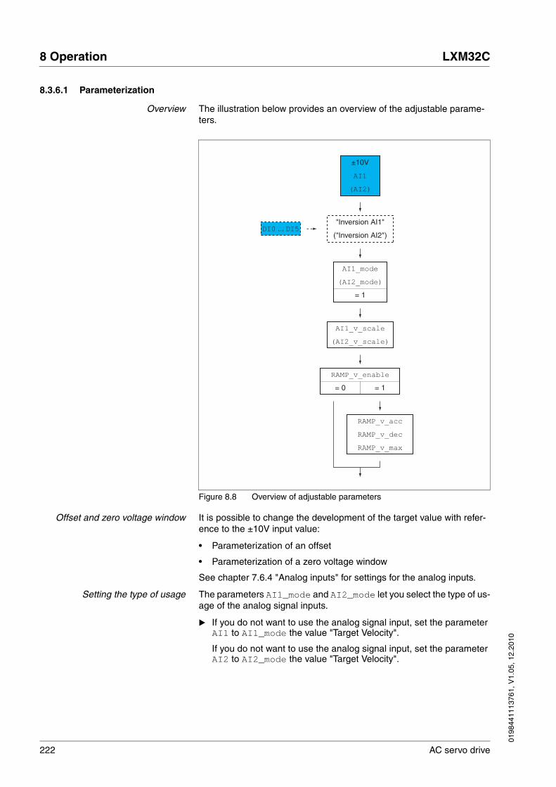
222 AC servo drive
8 Operation LXM32C
0198
4411
1376
1, V
1.05
, 12.
2010
8.3.6.1 Parameterization
Overview The illustration below provides an overview of the adjustable parame-ters.
Figure 8.8 Overview of adjustable parameters
Offset and zero voltage window It is possible to change the development of the target value with refer-ence to the ±10V input value:
• Parameterization of an offset
• Parameterization of a zero voltage window
See chapter 7.6.4 "Analog inputs" for settings for the analog inputs.
Setting the type of usage The parameters AI1_mode and AI2_mode let you select the type of us-age of the analog signal inputs.
� If you do not want to use the analog signal input, set the parameter AI1 to AI1_mode the value "Target Velocity".
If you do not want to use the analog signal input, set the parameter AI2 to AI2_mode the value "Target Velocity".
RAMP_v_max
RAMP_v_dec
RAMP_v_acc
AI1_v_scale
(AI2_v_scale)
RAMP_v_enable
DI0 ... DI5"Inversion AI1"
("Inversion AI2")
= 0 = 1
AI1_mode
(AI2_mode)
= 1
AI1
(AI2)
±10V

0198
4411
1376
1, V
1.05
, 12.
2010
LXM32C 8 Operation
AC servo drive 223
Setting the target velocity The parameters AI1_v_scale and AI2_v_scale are used to set the target velocity for a voltage value of +10.
� If you want to use the analog signal input AI1, use the parameter AI1_v_scale to set the desired target velocity for a voltage value of +10V.
If you want to use the analog signal input AI2, use the parameter AI2_v_scale to set the desired target velocity for a voltage value of +10V.
Parameter nameHMI menuHMI name
Description UnitMinimum valueFactory settingMaximum value
Data typeR/WPersistentExpert
Parameter address via fieldbus
AI1_mode
ConF → i-o-
A1Mo
Analog 1: Type of usage
0 / None / nonE: No function1 / Target Velocity / SPdS: Target velocity for the velocity controller2 / Target Torque / trqS: Target torque for the current controller3 / Velocity Limitation / LSPd: Limitation of the velocity for the velocity controller4 / Torque Limitation / Ltrq: Limitation of the torque for the current controller
Setting can only be changed if power stage is disabled.
Changed settings become active the next time the power stage is enabled.
-014
UINT16R/Wper.-
Modbus 2332
AI2_mode
ConF → i-o-
A2Mo
Analog 2: Type of usage
0 / None / nonE: No function1 / Target Velocity / SPdS: Target velocity for the velocity controller2 / Target Torque / trqS: Target torque for the current controller3 / Velocity Limitation / LSPd: Limitation of the velocity for the velocity controller4 / Torque Limitation / Ltrq: Limitation of the torque for the current controller
Setting can only be changed if power stage is disabled.
Changed settings become active the next time the power stage is enabled.
-004
UINT16R/Wper.-
Modbus 2342
Parameter nameHMI menuHMI name
Description UnitMinimum valueFactory settingMaximum value
Data typeR/WPersistentExpert
Parameter address via fieldbus
AI1_v_scale Analog 1: Target velocity at 10 V in operating mode Profile Velocity
The maximum velocity is limited to the set-ting in CTRL_v_max.
By using a negative sign, you can invert the evaluation of the analog signal.
Changed settings become active immedi-ately.
usr_v-214748364860002147483647
INT32R/Wper.-
Modbus 2338
224 AC servo drive
8 Operation LXM32C
0198
4411
1376
1, V
1.05
, 12.
2010
Changing the motion profile for thevelocity
It is possible to change the parameterization of the motion profile for the velocity, see chapter 8.5.3 "Setting the motion profile for the velocity".
8.3.6.2 Additional settings
The following functions can be used for target value processing:
• Chapter 8.6.1 "Stop movement with Halt"
• Chapter 8.6.2 "Stopping a movement with Quick Stop"
• Chapter 8.7.3 "Motor standstill"
• Chapter 8.6.3 "Inverting the analog signal inputs"
• Chapter 8.6.4 "Limitation of the velocity via signal inputs"
• Chapter 8.6.5 "Limitation of the current via signal inputs"
• Chapter 8.6.7 "Zero Clamp"
The following functions can be used for monitoring the movement:
• Chapter 8.7.1 "Limit switches"
• Chapter 8.7.5 "Velocity deviation window"
• Chapter 8.7.6 "Velocity threshold value"
• Chapter 8.7.7 "Current threshold value"
AI2_v_scale Analog 2: Target velocity at 10 V in operating mode Profile Velocity
The maximum velocity is limited to the set-ting in CTRL_v_max.
By using a negative sign, you can invert the evaluation of the analog signal.
Changed settings become active immedi-ately.
usr_v-214748364860002147483647
INT32R/Wper.-
Modbus 2348
Parameter nameHMI menuHMI name
Description UnitMinimum valueFactory settingMaximum value
Data typeR/WPersistentExpert
Parameter address via fieldbus
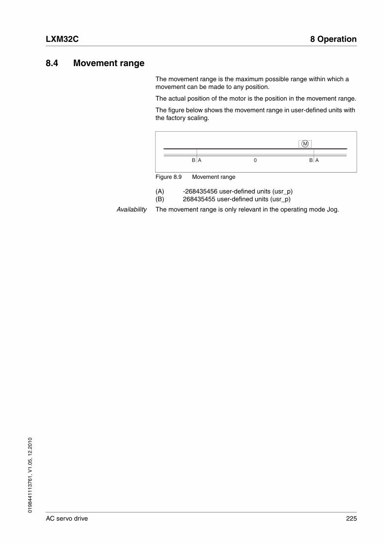
0198
4411
1376
1, V
1.05
, 12.
2010
LXM32C 8 Operation
AC servo drive 225
8.4 Movement range
The movement range is the maximum possible range within which a movement can be made to any position.
The actual position of the motor is the position in the movement range.
The figure below shows the movement range in user-defined units with the factory scaling.
Figure 8.9 Movement range
(A) -268435456 user-defined units (usr_p)(B) 268435455 user-defined units (usr_p)
Availability The movement range is only relevant in the operating mode Jog.
M
A ABB 0

226 AC servo drive
8 Operation LXM32C
0198
4411
1376
1, V
1.05
, 12.
2010
8.4.1 Scaling
Scaling converts user-defined units into internal units of the device, and vice versa.
Figure 8.10 Scaling
User-defined units User-defined units are values for positions, velocities, acceleration and deceleration; they have the following units:
• usr_p for positions
• usr_v for velocities
• usr_a for acceleration and deceleration
Scaling factor The scaling factor is the relationship between the motor movement and the required user-defined units. When specifying the scaling factor, note that numerator and denominator can only be integer values.
Commissioning software As of firmware version , you can adjust the scaling via the commission-ing software. The parameters with user-defined units are automatically checked and adjusted.
@ WARNINGUNEXPECTED MOVEMENT CAUSED BY CHANGED SCALING
Changing the scaling changes the effect of the values in user-defined units. The same user-defined units cause different movements when the scaling is changed.
• Note that scaling affects all relationships between the user-defined units and the movements.
• Check the parameters with user-defined units.
Failure to follow these instructions can result in death, serious injury or equipment damage.
E
M3~
Internalunits
Processingin internal
unitsScalingfactor
Scaling
Position
Velocity
AccelerationDeceleration
User-defined units

0198
4411
1376
1, V
1.05
, 12.
2010
LXM32C 8 Operation
AC servo drive 227
8.4.1.1 Configuration of position scaling
Position scaling is the relationship between the number of motor revolu-tions and the required user-defined units [usr_p].
Scaling factor Position scaling is specified by means of scaling factor:
In the case of a rotary motor, the scaling factor is calculated as shown below:
Figure 8.11 Scaling factor of position scaling
The scaling factor is set using the parameters POSscaleNum and POSscaleDenom. A new scaling factor is activated when you specify the numerator value.
Factory setting The following factory settings are used:
• 1 motor revolution corresponds to 16384 user-defined units
Number of revolutions of the motor
Number of user-defined units [usr_p]
Parameter nameHMI menuHMI name
Description UnitMinimum valueFactory settingMaximum value
Data typeR/WPersistentExpert
Parameter address via fieldbus
ScalePOSnum Position scaling: Numerator
Specification of the scaling factor:
Motor revolutions-------------------------------------------User-defined units [usr_p]
A new scaling is activated when the numera-tor value is supplied.
Setting can only be changed if power stage is disabled.
Changed settings become active immedi-ately.
revolution112147483647
INT32R/Wper.-
Modbus 1552
ScalePOSdenom Position scaling: Denominator
Refer to numerator (ScalePOSnum) for a description.
A new scaling is activated when the numera-tor value is supplied.
Setting can only be changed if power stage is disabled.
usr_p1163842147483647
INT32R/Wper.-
Modbus 1550

228 AC servo drive
8 Operation LXM32C
0198
4411
1376
1, V
1.05
, 12.
2010
8.4.1.2 Configuration of velocity scaling
Velocity scaling is the relationship between the number of motor revolu-tions per minute and the required user-defined units [usr_v].
Scaling factor Velocity scaling is specified by means of scaling factor:
In the case of a rotary motor, the scaling factor is calculated as shown below:
Figure 8.12 Scaling factor of velocity scaling
Factory setting The following factory settings are used:
• 1 motor revolution per minute corresponds to 1 user-defined unit
Number of revolutions of the motor per minute
Number of user-defined units [usr_v]
Parameter nameHMI menuHMI name
Description UnitMinimum valueFactory settingMaximum value
Data typeR/WPersistentExpert
Parameter address via fieldbus
ScaleVELnum Velocity scaling: Numerator
Specification of the scaling factor:
Speed of rotation of motor [min-1]--------------------------------------------------User-defined units [usr_v]
A new scaling is activated when the numera-tor value is supplied.
Setting can only be changed if power stage is disabled.
Changed settings become active immedi-ately.
min-1
112147483647
INT32R/Wper.-
Modbus 1604
ScaleVELdenom Velocity scaling: Denominator
Refer to numerator (ScaleVELnum) for a description.
A new scaling is activated when the numera-tor value is supplied.
Setting can only be changed if power stage is disabled.
usr_v112147483647
INT32R/Wper.-
Modbus 1602

0198
4411
1376
1, V
1.05
, 12.
2010
LXM32C 8 Operation
AC servo drive 229
8.4.1.3 Configuration of ramp scaling
Ramp scaling is the relationship between the change in velocity and the required user-defined units [usr_a].
Scaling factor Ramp scaling is specified by means of scaling factor:
Figure 8.13 Scaling factor of ramp scaling
Factory setting The following factory settings are used:
• A change of 1 motor revolution per minute per second corresponds to 1 user-defined unit.
Velocity change per second
Number of user-defined units [usr_a]
Parameter nameHMI menuHMI name
Description UnitMinimum valueFactory settingMaximum value
Data typeR/WPersistentExpert
Parameter address via fieldbus
ScaleRAMPnum Ramp scaling: Numerator
Setting can only be changed if power stage is disabled.
Changed settings become active immedi-ately.
min-1/s112147483647
INT32R/Wper.-
Modbus 1634
ScaleRAMPdenom Ramp scaling: Denominator
Refer to numerator (ScaleRAMPnum) for a description.
A new scaling is activated when the numera-tor value is supplied.
Setting can only be changed if power stage is disabled.
usr_a112147483647
INT32R/Wper.-
Modbus 1632

230 AC servo drive
8 Operation LXM32C
0198
4411
1376
1, V
1.05
, 12.
2010
8.5 Extended settings
8.5.1 Setting the PTO interface
The PTO interface allows you to make reference value signals from the device externally available.
The PTO interface can be used in one of 2 ways.
• Encoder simulation
• PTI signal
The parameter PTO_mode lets you set the way the PTO interface is used.
Encoder simulation The following types of encoder simulation are possible:
• Encoder simulation based on actual position of encoder 1
• Encoder simulation based on the reference position values (_p_ref)
The resolution for the encoder simulation is set with the parameter ESIM_scale.
PTI signal If the PTI signal is selected by means of parameter PTO_mode, the sig-nal from the PTI interface is directly made available at the PTO interface.
Parameter nameHMI menuHMI name
Description UnitMinimum valueFactory settingMaximum value
Data typeR/WPersistentExpert
Parameter address via fieldbus
PTO_mode Type of usage of PTO interface
0 / Off: PTO interface disabled1 / Esim pAct Enc 1: Encoder simulation based on actual position of encoder 12 / Esim pRef: Encoder simulation based on reference position values (_p_ref)3 / PTI Signal: Directly the signal from PTI interface
Setting can only be changed if power stage is disabled.
Changed settings become active the next time the power stage is enabled.
-013
UINT16R/Wper.-
Modbus 1342
Parameter nameHMI menuHMI name
Description UnitMinimum valueFactory settingMaximum value
Data typeR/WPersistentExpert
Parameter address via fieldbus
ESIM_scale
ConF → i-o-
ESSC
Resolution of encoder simulation
Resolution defines the number of increments per revolution (AB signal with quadruple evaluation).
The index pulse is created once per revolu-tion at an interval where signal A and signal B are high.
Setting can only be changed if power stage is disabled.
Changed settings become active the next time the product is switched on.
EncInc8409665535
UINT16R/Wper.-
Modbus 1322

0198
4411
1376
1, V
1.05
, 12.
2010
LXM32C 8 Operation
AC servo drive 231
8.5.2 Setting the digital signal inputs and signal outputs
Different signal functions can be assigned to the digital signal inputs and digital signal outputs.
Depending on the selected operating mode, different functions are as-signed to the digital signal inputs and digital signal outputs.
Current state The parameters _IO_DI_act and _IO_DQ_act can be used to read the status of the digital signal inputs and the digital signal outputs.
@ WARNINGUNINTENDED BEHAVIOR OF INPUTS AND OUTPUTS
The functions of the inputs and outputs depend on the selected oper-ating mode and the settings of the corresponding parameters.
• Verify that the wiring is appropriate for the settings.
• Only start the system if there are no persons or obstructions in the hazardous area.
• When commissioning, carefully run tests for all operating states and potential fault situations.
Failure to follow these instructions can result in death, serious injury or equipment damage.
Parameter nameHMI menuHMI name
Description UnitMinimum valueFactory settingMaximum value
Data typeR/WPersistentExpert
Parameter address via fieldbus
_IO_DI_act
Mon
diMo
Status of digital inputs
Bit assignments:Bit 0: DI0Bit 1: DI1Bit 2: DI2Bit 3: DI3Bit 4: DI4Bit 5: DI5
----
UINT16R/---
Modbus 2078
_IO_DQ_act
Mon
doMo
Status of digital outputs
Bit assignments:Bit 0: DQ0Bit 1: DQ1Bit 2: DQ2Bit 3: DQ3Bit 4: DQ4
----
UINT16R/---
Modbus 2080

232 AC servo drive
8 Operation LXM32C
0198
4411
1376
1, V
1.05
, 12.
2010
Factory settings The table below shows the factory settings of the digital signal inputs de-pending on the selected operating mode:
The table below shows the factory settings of the digital signal outputs depending on the selected operating mode:
When the operating mode is changed and after the product is switched off and on, the factory settings are assigned to the digital signal inputs and digital signal outputs.
Signal Jog Electronic Gear Profile Torque Profile Velocity
DI0 Enable Enable Enable Enable
DI1 Fault Reset Fault Reset Fault Reset Fault Reset
DI2 Positive Limit Switch (LIMP)
Positive Limit Switch (LIMP)
Operating Mode Switch Operating Mode Switch
DI3 Negative Limit Switch (LIMN)
Negative Limit Switch (LIMN)
Velocity Limitation Velocity Limitation
DI4 Jog negative Gear Ratio Switch Current Limitation Zero Clamp
DI5 Jog positive Halt Halt Halt
Signal Jog Electronic Gear Profile Torque Profile Velocity
DQ0 No Fault No Fault No Fault No Fault
DQ1 Active Active Active Active
DQ2 In Position Deviation Win-dow
In Position Deviation Win-dow
Current Threshold Reached
In Velocity Deviation Win-dow
DQ3 Motor Standstill Motor Standstill Motor Standstill Motor Standstill
DQ4 Selected Error Output Selected Error Output Selected Error Output Selected Error Output

0198
4411
1376
1, V
1.05
, 12.
2010
LXM32C 8 Operation
AC servo drive 233
8.5.2.1 Configuration of signal inputs
The table below provides an overview of the possible signal input func-tions depending on the selected operating mode:
The following parameters can be used to parameterize the digital signal inputs:
Signal input function Jog Electronic Gear
Profile Torque
Profile Velocity
Description in chapter
Freely Available • • • • No function
Fault Reset • • • • 8.2 "Operating states"
Enable • • • • 8.2 "Operating states"
Halt • • • • 8.6.1 "Stop movement with Halt"
Current Limitation • • • • 8.6.5 "Limitation of the current via signal inputs"
Zero Clamp • • 8.6.7 "Zero Clamp"
Velocity Limitation • • • • 8.6.4 "Limitation of the velocity via signal inputs"
Jog Positive • 8.3.3 "Operating mode Jog"
Jog Negative • 8.3.3 "Operating mode Jog"
Jog Fast/Slow • 8.3.3 "Operating mode Jog"
Gear Ratio Switch • 8.3.4 "Operating mode Electronic Gear"
Gear Offset 1 • 8.3.4 "Operating mode Electronic Gear"
Gear Offset 2 • 8.3.4 "Operating mode Electronic Gear"
Positive Limit Switch (LIMP) • • • • 8.7.1 "Limit switches"
Negative Limit Switch (LIMN) • • • • 8.7.1 "Limit switches"
Switch Controller Parameter Set • • • • 8.5.4.5 "Parameterizable controller parameter"
Inversion AI1 • • 8.6.3 "Inverting the analog signal inputs"
Inversion AI2 • • 8.6.3 "Inverting the analog signal inputs"
Operating Mode Switch • • • • 8.3.2 "Changing the operating mode"
Velocity Controller Integral Off • • • • 8.5.4.9 "Deactivating the integral term"

234 AC servo drive
8 Operation LXM32C
0198
4411
1376
1, V
1.05
, 12.
2010
Parameter nameHMI menuHMI name
Description UnitMinimum valueFactory settingMaximum value
Data typeR/WPersistentExpert
Parameter address via fieldbus
IOfunct_DI0
ConF → i-o-
di0
Function Input DI0
1 / Freely Available / nonE: Available as required2 / Fault Reset / FrES: Fault reset after error3 / Enable / EnAb: Enables the power stage4 / Halt / hALt: Halt6 / Current Limitation / iLiM: Limits the cur-rent to parameter value7 / Zero Clamp / CLMP: Zero clamping8 / Velocity Limitation / VLiM: Limits the velocity to parameter value9 / Jog Positive / JoGP: Jog: Moves in posi-tive direction10 / Jog Negative / JoGn: Jog: Moves in negative direction11 / Jog Fast/Slow / JoGF: Jog: Switches between slow and fast movement12 / Gear Ratio Switch / GrAt: Electronic Gear: Switches between two gear ratios19 / Gear Offset 1 / GoF1: Electronic Gear: Adds first gear offset20 / Gear Offset 2 / GoF2: Electronic Gear: Adds second gear offset21 / Reference Switch (REF) / rEF: Refer-ence switch22 / Positive Limit Switch (LIMP) / LiMP: Positive limit switch23 / Negative Limit Switch (LIMN) / LiMn: Negative limit switch24 / Switch Controller Parameter Set / CPAr: Switches controller parameter set25 / Inversion AI1 / A1iV: Inverts analog input AI126 / Inversion AI2 / A2iV: Inverts analog input AI227 / Operating Mode Switch / MSWt: Switches operating mode28 / Velocity Controller Integral Off / tnoF: Switches off velocity controller integral term
Setting can only be changed if power stage is disabled.
Changed settings become active the next time the product is switched on.
----
UINT16R/Wper.-
Modbus 1794

0198
4411
1376
1, V
1.05
, 12.
2010
LXM32C 8 Operation
AC servo drive 235
IOfunct_DI1
ConF → i-o-
di1
Function Input DI1
1 / Freely Available / nonE: Available as required2 / Fault Reset / FrES: Fault reset after error3 / Enable / EnAb: Enables the power stage4 / Halt / hALt: Halt6 / Current Limitation / iLiM: Limits the cur-rent to parameter value7 / Zero Clamp / CLMP: Zero clamping8 / Velocity Limitation / VLiM: Limits the velocity to parameter value9 / Jog Positive / JoGP: Jog: Moves in posi-tive direction10 / Jog Negative / JoGn: Jog: Moves in negative direction11 / Jog Fast/Slow / JoGF: Jog: Switches between slow and fast movement12 / Gear Ratio Switch / GrAt: Electronic Gear: Switches between two gear ratios19 / Gear Offset 1 / GoF1: Electronic Gear: Adds first gear offset20 / Gear Offset 2 / GoF2: Electronic Gear: Adds second gear offset21 / Reference Switch (REF) / rEF: Refer-ence switch22 / Positive Limit Switch (LIMP) / LiMP: Positive limit switch23 / Negative Limit Switch (LIMN) / LiMn: Negative limit switch24 / Switch Controller Parameter Set / CPAr: Switches controller parameter set25 / Inversion AI1 / A1iV: Inverts analog input AI126 / Inversion AI2 / A2iV: Inverts analog input AI227 / Operating Mode Switch / MSWt: Switches operating mode28 / Velocity Controller Integral Off / tnoF: Switches off velocity controller integral term
Setting can only be changed if power stage is disabled.
Changed settings become active the next time the product is switched on.
----
UINT16R/Wper.-
Modbus 1796
Parameter nameHMI menuHMI name
Description UnitMinimum valueFactory settingMaximum value
Data typeR/WPersistentExpert
Parameter address via fieldbus

236 AC servo drive
8 Operation LXM32C
0198
4411
1376
1, V
1.05
, 12.
2010
IOfunct_DI2
ConF → i-o-
di2
Function Input DI2
1 / Freely Available / nonE: Available as required2 / Fault Reset / FrES: Fault reset after error3 / Enable / EnAb: Enables the power stage4 / Halt / hALt: Halt6 / Current Limitation / iLiM: Limits the cur-rent to parameter value7 / Zero Clamp / CLMP: Zero clamping8 / Velocity Limitation / VLiM: Limits the velocity to parameter value9 / Jog Positive / JoGP: Jog: Moves in posi-tive direction10 / Jog Negative / JoGn: Jog: Moves in negative direction11 / Jog Fast/Slow / JoGF: Jog: Switches between slow and fast movement12 / Gear Ratio Switch / GrAt: Electronic Gear: Switches between two gear ratios19 / Gear Offset 1 / GoF1: Electronic Gear: Adds first gear offset20 / Gear Offset 2 / GoF2: Electronic Gear: Adds second gear offset21 / Reference Switch (REF) / rEF: Refer-ence switch22 / Positive Limit Switch (LIMP) / LiMP: Positive limit switch23 / Negative Limit Switch (LIMN) / LiMn: Negative limit switch24 / Switch Controller Parameter Set / CPAr: Switches controller parameter set25 / Inversion AI1 / A1iV: Inverts analog input AI126 / Inversion AI2 / A2iV: Inverts analog input AI227 / Operating Mode Switch / MSWt: Switches operating mode28 / Velocity Controller Integral Off / tnoF: Switches off velocity controller integral term
Setting can only be changed if power stage is disabled.
Changed settings become active the next time the product is switched on.
----
UINT16R/Wper.-
Modbus 1798
Parameter nameHMI menuHMI name
Description UnitMinimum valueFactory settingMaximum value
Data typeR/WPersistentExpert
Parameter address via fieldbus

0198
4411
1376
1, V
1.05
, 12.
2010
LXM32C 8 Operation
AC servo drive 237
IOfunct_DI3
ConF → i-o-
di3
Function Input DI3
1 / Freely Available / nonE: Available as required2 / Fault Reset / FrES: Fault reset after error3 / Enable / EnAb: Enables the power stage4 / Halt / hALt: Halt6 / Current Limitation / iLiM: Limits the cur-rent to parameter value7 / Zero Clamp / CLMP: Zero clamping8 / Velocity Limitation / VLiM: Limits the velocity to parameter value9 / Jog Positive / JoGP: Jog: Moves in posi-tive direction10 / Jog Negative / JoGn: Jog: Moves in negative direction11 / Jog Fast/Slow / JoGF: Jog: Switches between slow and fast movement12 / Gear Ratio Switch / GrAt: Electronic Gear: Switches between two gear ratios19 / Gear Offset 1 / GoF1: Electronic Gear: Adds first gear offset20 / Gear Offset 2 / GoF2: Electronic Gear: Adds second gear offset21 / Reference Switch (REF) / rEF: Refer-ence switch22 / Positive Limit Switch (LIMP) / LiMP: Positive limit switch23 / Negative Limit Switch (LIMN) / LiMn: Negative limit switch24 / Switch Controller Parameter Set / CPAr: Switches controller parameter set25 / Inversion AI1 / A1iV: Inverts analog input AI126 / Inversion AI2 / A2iV: Inverts analog input AI227 / Operating Mode Switch / MSWt: Switches operating mode28 / Velocity Controller Integral Off / tnoF: Switches off velocity controller integral term
Setting can only be changed if power stage is disabled.
Changed settings become active the next time the product is switched on.
----
UINT16R/Wper.-
Modbus 1800
Parameter nameHMI menuHMI name
Description UnitMinimum valueFactory settingMaximum value
Data typeR/WPersistentExpert
Parameter address via fieldbus

238 AC servo drive
8 Operation LXM32C
0198
4411
1376
1, V
1.05
, 12.
2010
IOfunct_DI4
ConF → i-o-
di4
Function Input DI4
1 / Freely Available / nonE: Available as required2 / Fault Reset / FrES: Fault reset after error3 / Enable / EnAb: Enables the power stage4 / Halt / hALt: Halt6 / Current Limitation / iLiM: Limits the cur-rent to parameter value7 / Zero Clamp / CLMP: Zero clamping8 / Velocity Limitation / VLiM: Limits the velocity to parameter value9 / Jog Positive / JoGP: Jog: Moves in posi-tive direction10 / Jog Negative / JoGn: Jog: Moves in negative direction11 / Jog Fast/Slow / JoGF: Jog: Switches between slow and fast movement12 / Gear Ratio Switch / GrAt: Electronic Gear: Switches between two gear ratios19 / Gear Offset 1 / GoF1: Electronic Gear: Adds first gear offset20 / Gear Offset 2 / GoF2: Electronic Gear: Adds second gear offset21 / Reference Switch (REF) / rEF: Refer-ence switch22 / Positive Limit Switch (LIMP) / LiMP: Positive limit switch23 / Negative Limit Switch (LIMN) / LiMn: Negative limit switch24 / Switch Controller Parameter Set / CPAr: Switches controller parameter set25 / Inversion AI1 / A1iV: Inverts analog input AI126 / Inversion AI2 / A2iV: Inverts analog input AI227 / Operating Mode Switch / MSWt: Switches operating mode28 / Velocity Controller Integral Off / tnoF: Switches off velocity controller integral term
Setting can only be changed if power stage is disabled.
Changed settings become active the next time the product is switched on.
----
UINT16R/Wper.-
Modbus 1802
Parameter nameHMI menuHMI name
Description UnitMinimum valueFactory settingMaximum value
Data typeR/WPersistentExpert
Parameter address via fieldbus

0198
4411
1376
1, V
1.05
, 12.
2010
LXM32C 8 Operation
AC servo drive 239
IOfunct_DI5
ConF → i-o-
di5
Function Input DI5
1 / Freely Available / nonE: Available as required2 / Fault Reset / FrES: Fault reset after error3 / Enable / EnAb: Enables the power stage4 / Halt / hALt: Halt6 / Current Limitation / iLiM: Limits the cur-rent to parameter value7 / Zero Clamp / CLMP: Zero clamping8 / Velocity Limitation / VLiM: Limits the velocity to parameter value9 / Jog Positive / JoGP: Jog: Moves in posi-tive direction10 / Jog Negative / JoGn: Jog: Moves in negative direction11 / Jog Fast/Slow / JoGF: Jog: Switches between slow and fast movement12 / Gear Ratio Switch / GrAt: Electronic Gear: Switches between two gear ratios19 / Gear Offset 1 / GoF1: Electronic Gear: Adds first gear offset20 / Gear Offset 2 / GoF2: Electronic Gear: Adds second gear offset21 / Reference Switch (REF) / rEF: Refer-ence switch22 / Positive Limit Switch (LIMP) / LiMP: Positive limit switch23 / Negative Limit Switch (LIMN) / LiMn: Negative limit switch24 / Switch Controller Parameter Set / CPAr: Switches controller parameter set25 / Inversion AI1 / A1iV: Inverts analog input AI126 / Inversion AI2 / A2iV: Inverts analog input AI227 / Operating Mode Switch / MSWt: Switches operating mode28 / Velocity Controller Integral Off / tnoF: Switches off velocity controller integral term
Setting can only be changed if power stage is disabled.
Changed settings become active the next time the product is switched on.
----
UINT16R/Wper.-
Modbus 1804
Parameter nameHMI menuHMI name
Description UnitMinimum valueFactory settingMaximum value
Data typeR/WPersistentExpert
Parameter address via fieldbus

240 AC servo drive
8 Operation LXM32C
0198
4411
1376
1, V
1.05
, 12.
2010
8.5.2.2 Configuration of the signal outputs
The table below provides an overview of the possible signal output func-tions depending on the selected operating mode:
The following parameters can be used to parameterize the digital signal outputs:
Signal output function Jog Electronic Gear
Profile Torque
Profile Velocity
Description in chapter
Freely Available • • • •
No Fault • • • • 8.2.3 "Indication of the operating state"
Active • • • • 8.2.3 "Indication of the operating state"
In Position Deviation Window • • 8.7.4 "Position deviation window"
In Velocity Deviation Window • • • 8.7.5 "Velocity deviation window"
Velocity Threshold Reached • • • • 8.7.6 "Velocity threshold value"
Current Threshold Reached • • • • 8.7.7 "Current threshold value"
Halt Acknowledge • • • • 8.6.1 "Stop movement with Halt"
Motor Standstill • • • • 8.7.3 "Motor standstill"
Selected Error • • • • 8.2.3 "Indication of the operating state"
Selected Warning • • • • 8.2.3 "Indication of the operating state"
Parameter nameHMI menuHMI name
Description UnitMinimum valueFactory settingMaximum value
Data typeR/WPersistentExpert
Parameter address via fieldbus
IOfunct_DQ0
ConF → i-o-
do0
Function Output DQ0
1 / Freely Available / nonE: Available as required2 / No Fault / nFLt: Signals operating states Ready To Switch On, Switched On and Operation Enable3 / Active / Acti: Signals operating state Operation Enable5 / In Position Deviation Window / in-P: Position deviation is within window6 / In Velocity Deviation Window / in-V: Velocity deviation is within window7 / Velocity Below Threshold / Vthr: Motor velocity below threshold8 / Current Below Threshold / ithr: Motor current below threshold9 / Halt Acknowledge / hALt: Halt acknowl-edgement13 / Motor Standstill / MStd: Motor at a standstill14 / Selected Error / SErr: One of the selected errors is active16 / Selected Warning / SWrn: One of the selected warnings is active
Setting can only be changed if power stage is disabled.
Changed settings become active the next time the product is switched on.
----
UINT16R/Wper.-
Modbus 1810

0198
4411
1376
1, V
1.05
, 12.
2010
LXM32C 8 Operation
AC servo drive 241
IOfunct_DQ1
ConF → i-o-
do1
Function Output DQ1
1 / Freely Available / nonE: Available as required2 / No Fault / nFLt: Signals operating states Ready To Switch On, Switched On and Operation Enable3 / Active / Acti: Signals operating state Operation Enable5 / In Position Deviation Window / in-P: Position deviation is within window6 / In Velocity Deviation Window / in-V: Velocity deviation is within window7 / Velocity Below Threshold / Vthr: Motor velocity below threshold8 / Current Below Threshold / ithr: Motor current below threshold9 / Halt Acknowledge / hALt: Halt acknowl-edgement13 / Motor Standstill / MStd: Motor at a standstill14 / Selected Error / SErr: One of the selected errors is active16 / Selected Warning / SWrn: One of the selected warnings is active
Setting can only be changed if power stage is disabled.
Changed settings become active the next time the product is switched on.
----
UINT16R/Wper.-
Modbus 1812
IOfunct_DQ2
ConF → i-o-
do2
Function Output DQ2
1 / Freely Available / nonE: Available as required2 / No Fault / nFLt: Signals operating states Ready To Switch On, Switched On and Operation Enable3 / Active / Acti: Signals operating state Operation Enable5 / In Position Deviation Window / in-P: Position deviation is within window6 / In Velocity Deviation Window / in-V: Velocity deviation is within window7 / Velocity Below Threshold / Vthr: Motor velocity below threshold8 / Current Below Threshold / ithr: Motor current below threshold9 / Halt Acknowledge / hALt: Halt acknowl-edgement13 / Motor Standstill / MStd: Motor at a standstill14 / Selected Error / SErr: One of the selected errors is active16 / Selected Warning / SWrn: One of the selected warnings is active
Setting can only be changed if power stage is disabled.
Changed settings become active the next time the product is switched on.
----
UINT16R/Wper.-
Modbus 1814
Parameter nameHMI menuHMI name
Description UnitMinimum valueFactory settingMaximum value
Data typeR/WPersistentExpert
Parameter address via fieldbus

242 AC servo drive
8 Operation LXM32C
0198
4411
1376
1, V
1.05
, 12.
2010
IOfunct_DQ3
ConF → i-o-
do3
Function Output DQ3
1 / Freely Available / nonE: Available as required2 / No Fault / nFLt: Signals operating states Ready To Switch On, Switched On and Operation Enable3 / Active / Acti: Signals operating state Operation Enable5 / In Position Deviation Window / in-P: Position deviation is within window6 / In Velocity Deviation Window / in-V: Velocity deviation is within window7 / Velocity Below Threshold / Vthr: Motor velocity below threshold8 / Current Below Threshold / ithr: Motor current below threshold9 / Halt Acknowledge / hALt: Halt acknowl-edgement13 / Motor Standstill / MStd: Motor at a standstill14 / Selected Error / SErr: One of the selected errors is active16 / Selected Warning / SWrn: One of the selected warnings is active
Setting can only be changed if power stage is disabled.
Changed settings become active the next time the product is switched on.
----
UINT16R/Wper.-
Modbus 1816
IOfunct_DQ4
ConF → i-o-
do4
Function Output DQ4
1 / Freely Available / nonE: Available as required2 / No Fault / nFLt: Signals operating states Ready To Switch On, Switched On and Operation Enable3 / Active / Acti: Signals operating state Operation Enable5 / In Position Deviation Window / in-P: Position deviation is within window6 / In Velocity Deviation Window / in-V: Velocity deviation is within window7 / Velocity Below Threshold / Vthr: Motor velocity below threshold8 / Current Below Threshold / ithr: Motor current below threshold9 / Halt Acknowledge / hALt: Halt acknowl-edgement13 / Motor Standstill / MStd: Motor at a standstill14 / Selected Error / SErr: One of the selected errors is active16 / Selected Warning / SWrn: One of the selected warnings is active
Setting can only be changed if power stage is disabled.
Changed settings become active the next time the product is switched on.
----
UINT16R/Wper.-
Modbus 1818
Parameter nameHMI menuHMI name
Description UnitMinimum valueFactory settingMaximum value
Data typeR/WPersistentExpert
Parameter address via fieldbus
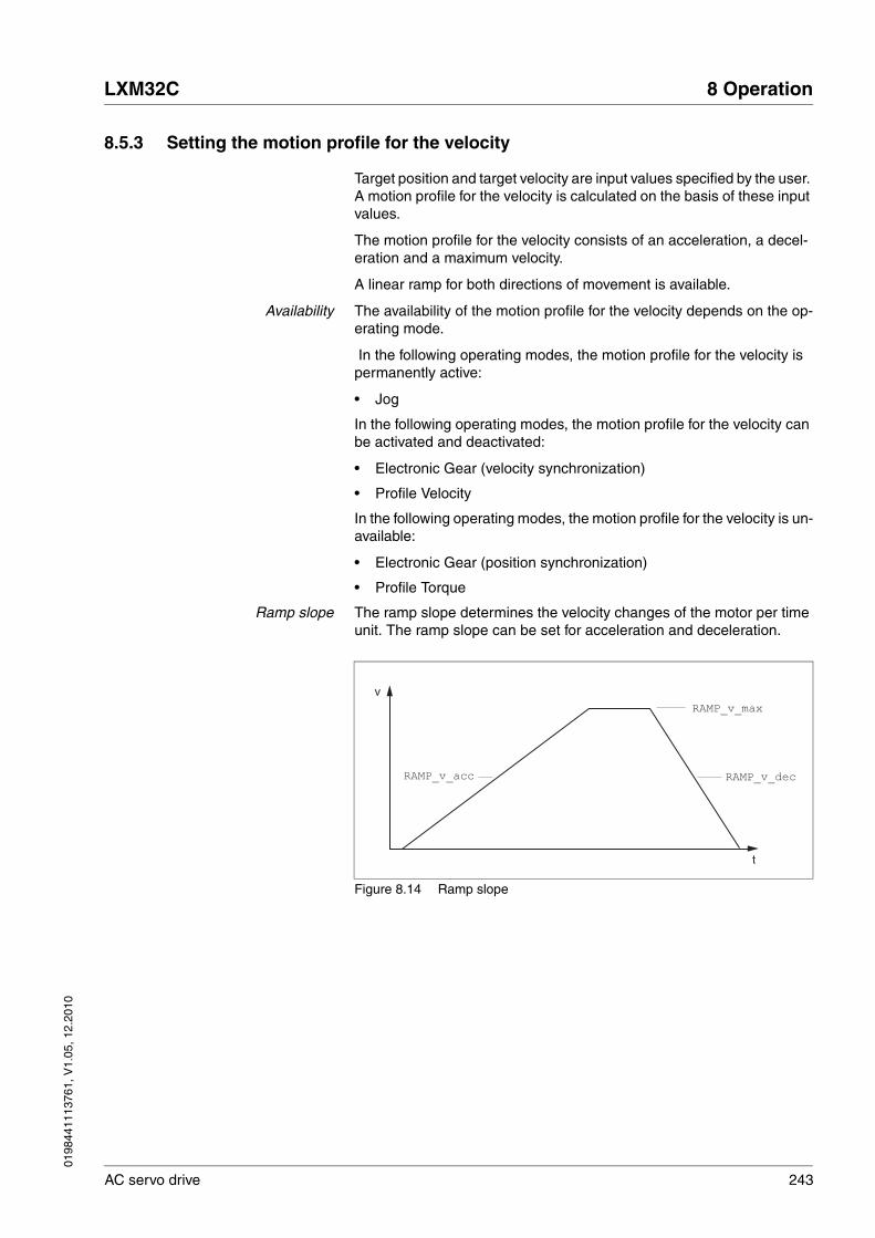
0198
4411
1376
1, V
1.05
, 12.
2010
LXM32C 8 Operation
AC servo drive 243
8.5.3 Setting the motion profile for the velocity
Target position and target velocity are input values specified by the user. A motion profile for the velocity is calculated on the basis of these input values.
The motion profile for the velocity consists of an acceleration, a decel-eration and a maximum velocity.
A linear ramp for both directions of movement is available.
Availability The availability of the motion profile for the velocity depends on the op-erating mode.
In the following operating modes, the motion profile for the velocity is permanently active:
• Jog
In the following operating modes, the motion profile for the velocity can be activated and deactivated:
• Electronic Gear (velocity synchronization)
• Profile Velocity
In the following operating modes, the motion profile for the velocity is un-available:
• Electronic Gear (position synchronization)
• Profile Torque
Ramp slope The ramp slope determines the velocity changes of the motor per time unit. The ramp slope can be set for acceleration and deceleration.
Figure 8.14 Ramp slope
t
vRAMP_v_max
RAMP_v_acc RAMP_v_dec

244 AC servo drive
8 Operation LXM32C
0198
4411
1376
1, V
1.05
, 12.
2010
Parameter nameHMI menuHMI name
Description UnitMinimum valueFactory settingMaximum value
Data typeR/WPersistentExpert
Parameter address via fieldbus
RAMP_v_enable Activation of the motion profile for velocity
0 / Profile Off: Profile off1 / Profile On: Profile on
The motion profile for velocity can be acti-vated or deactivated for the operating modes Profile Velocity and Electronic Gear (velocity synchronization).
Setting can only be changed if power stage is disabled.
Changed settings become active immedi-ately.
-001
UINT16R/Wper.-
Modbus 1622
RAMP_v_max
ConF → ACG-
nrMP
Maximum velocity of the motion profile for velocity
If a greater reference speed is set in one of these operating modes, it is automatically limited to RAMP_v_max.This way, commissioning at limited speed is easier to perform.
Setting can only be changed if power stage is disabled.
Changed settings become active the next time the motor moves.
usr_v1132002147483647
UINT32R/Wper.-
Modbus 1554
RAMP_v_acc Acceleration of the motion profile for velocity
Writing the value 0 has no effect on the parameter.
Changed settings become active the next time the motor moves.
usr_a16002147483647
UINT32R/Wper.-
Modbus 1556
RAMP_v_dec Deceleration of the motion profile for velocity
The minimum value depends on the operat-ing mode:
Operating modes with minimum value 1:Electronic Gear (velocity synchronization)Profile Velocity
Operating modes with minimum value 120:Jog
Writing the value 0 has no effect on the parameter.
Changed settings become active the next time the motor moves.
usr_a16002147483647
UINT32R/Wper.-
Modbus 1558

0198
4411
1376
1, V
1.05
, 12.
2010
LXM32C 8 Operation
AC servo drive 245
8.5.4 Setting the controller parameters
8.5.4.1 Overview of the controller structure
The illustration below shows an overview of the controller structure.
Figure 8.15 Controller structure, overview
(1) Position controller(2) Velocity controller(3) Current controller(4) Encoder evaluation
Position controller The position controller reduces the difference between the reference po-sition and the actual position of the motor (position deviation) to a mini-mum. When the motor is at a standstill, the position deviation is close to zero in the case of a well-tuned position controller.
An optimized velocity control loop is a prerequisite for good amplification of the position controller.
Velocity controller The velocity controller controls the motor velocity by varying the motor current depending on the load situation. The velocity controller has a de-cisive influence on the dynamic response of the drive. The dynamics of the velocity controller depend on:
• Moment of inertia of the drive and the controlled system
• Power of the motor
• Stiffness and elasticity of the elements in the flow of forces
• Backlash of the drive elements
• Friction
Current controller The current controller determines the torque of the motor. The current controller is automatically optimally tuned with the stored motor data.
M3~
E
_v_act, _n_act
_p_act, _p_actInt
A B C
4
321
_Iq_act_rms, _Id_act_rms
P V C

246 AC servo drive
8 Operation LXM32C
0198
4411
1376
1, V
1.05
, 12.
2010
8.5.4.2 Overview of position controller
The illustration below shows an overview of the position controller.
Figure 8.16 Position controller
(1) Reference value signals for the operating mode Electronic Gear with the methods "Position Synchronization Without Compensation Movement" and "Position Synchronization With Compensation Movement"
(2) Evaluation of the reference value signal for the operating mode Electronic Gear
(3) Target values for the operating mode Jog(4) Motion profile for the velocity(5) Velocity feed-forward control(6) Position controller
_p_PTI_act
_v_PTI_act
CTRL1_KPp
_p_dif_comp
A
2
6
_pref_v
CTRL1_KFPp
5
4
-
_p_act, _p_actInt
RAMP_v_max
RAMP_v_acc
RAMP_v_dec
RAMP_v_jerk
1
3
P_p_ref
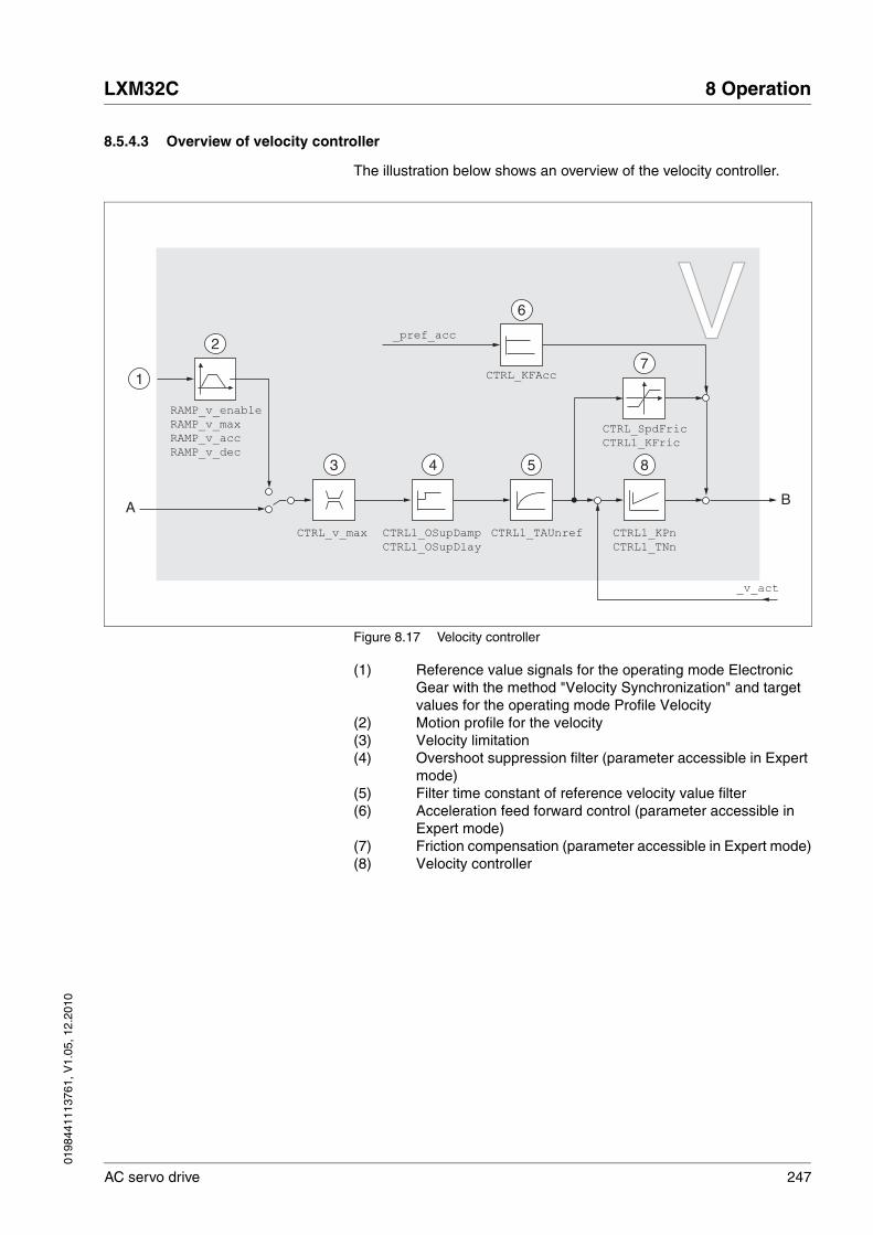
0198
4411
1376
1, V
1.05
, 12.
2010
LXM32C 8 Operation
AC servo drive 247
8.5.4.3 Overview of velocity controller
The illustration below shows an overview of the velocity controller.
Figure 8.17 Velocity controller
(1) Reference value signals for the operating mode Electronic Gear with the method "Velocity Synchronization" and target values for the operating mode Profile Velocity
(2) Motion profile for the velocity(3) Velocity limitation(4) Overshoot suppression filter (parameter accessible in Expert
mode)(5) Filter time constant of reference velocity value filter(6) Acceleration feed forward control (parameter accessible in
Expert mode)(7) Friction compensation (parameter accessible in Expert mode)(8) Velocity controller
VV
CTRL1_TAUnref CTRL1_KPn
CTRL1_TNn
1
A B
854
CTRL_SpdFric
CTRL1_KFric
CTRL1_OSupDamp
CTRL1_OSupDlay
CTRL_v_max
7
3
2
_v_act
RAMP_v_enable
RAMP_v_max
RAMP_v_acc
RAMP_v_dec
_pref_acc
CTRL_KFAcc
6
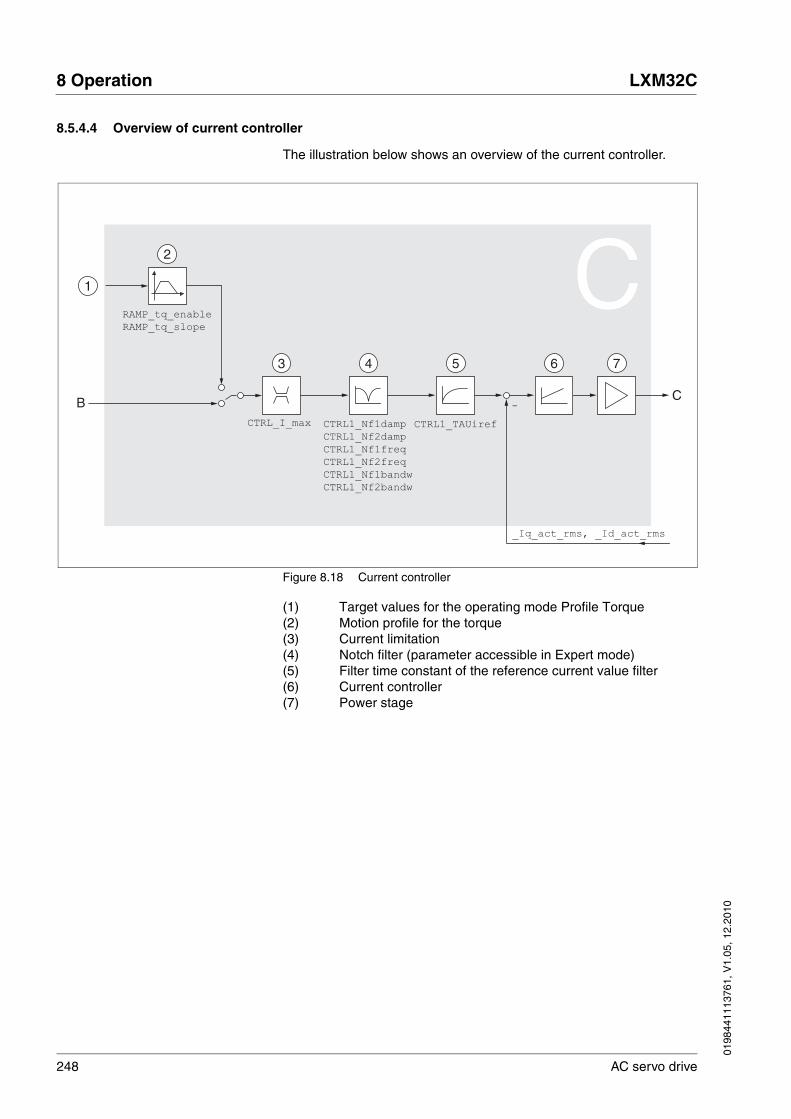
248 AC servo drive
8 Operation LXM32C
0198
4411
1376
1, V
1.05
, 12.
2010
8.5.4.4 Overview of current controller
The illustration below shows an overview of the current controller.
Figure 8.18 Current controller
(1) Target values for the operating mode Profile Torque(2) Motion profile for the torque(3) Current limitation(4) Notch filter (parameter accessible in Expert mode)(5) Filter time constant of the reference current value filter(6) Current controller(7) Power stage
CTRL1_TAUiref
6 7
CB
54
CTRL1_Nf1damp
CTRL1_Nf2damp
CTRL1_Nf1freq
CTRL1_Nf2freq
CTRL1_Nf1bandw
CTRL1_Nf2bandw
CTRL_I_max
3
-
_Iq_act_rms, _Id_act_rms
1
2
RAMP_tq_enable
RAMP_tq_slope
C
0198
4411
1376
1, V
1.05
, 12.
2010
LXM32C 8 Operation
AC servo drive 249
8.5.4.5 Parameterizable controller parameter
The product features 2 controller parameter sets that can be parameter-ized separately. The values for the controller parameters determined during autotuning are stored in controller parameter set 1.
Controller parameter set A controller parameter set consists of freely accessible parameters and parameters which are only accessible in Expert mode.
See chapters 8.5.4.10 "Controller parameter set 1" and 8.5.4.11 "Con-troller parameter set 2".
Parameterization • Selecting a controller parameter set
Select a controller parameter set after switching on.
See chapter 8.5.4.6 "Selecting a controller parameter set".
• Automatically switching between control parameter sets
It is possible to switch between the two controller parameter sets.
See chapter 8.5.4.7 "Automatically switching between control parameter sets".
• Copying a controller parameter set
The values of controller parameter set 1 can be copied to controller parameter set 2.
See chapter 8.5.4.8 "Copying a controller parameter set".
• Deactivating the integral term
The integral term and, by implication, the integral action time, can be switched off via a digital signal input.
See chapter 8.5.4.9 "Deactivating the integral term".
Controller parameter set 1 Controller parameter set 2
Freely accessible parameters:
CTRL1_KPnCTRL1_TNnCTRL1_KPpCTRL1_TAUirefCTRL1_TAUnrefCTRL1_KFPp
Parameters only accessible in expert mode:
CTRL1_Nf1dampCTRL1_Nf1freqCTRL1_Nf1bandwCTRL1_Nf2dampCTRL1_Nf2freqCTRL1_Nf2bandwCTRL1_OsupdampCTRL1_OsupdelayCTRL1_Kfric
Freely accessible parameters:
CTRL2_KPnCTRL2_TNnCTRL2_KPpCTRL2_TAUirefCTRL2_TAUnrefCTRL2_KFPp
Parameters only accessible in expert mode:
CTRL2_Nf1dampCTRL2_Nf1freqCTRL2_Nf1bandwCTRL2_Nf2dampCTRL2_Nf2freqCTRL2_Nf2bandwCTRL2_OsupdampCTRL2_OsupdelayCTRL2_Kfric

250 AC servo drive
8 Operation LXM32C
0198
4411
1376
1, V
1.05
, 12.
2010
8.5.4.6 Selecting a controller parameter set
The currently active controller parameter set is indicated via the param-eter _CTRL_ActParSet.
The parameter CTRL_PwrUpParSet allows you to set the controller pa-rameter set to be activated after switching on. Alternatively, you can set whether or not the product is to switch automatically between the two controller parameter sets.
The parameter CTRL_SelParSet allows you to switch between the two controller parameter sets during operation.
Parameter nameHMI menuHMI name
Description UnitMinimum valueFactory settingMaximum value
Data typeR/WPersistentExpert
Parameter address via fieldbus
_CTRL_ActParSet Active controller parameter set
Value 1: Controller parameter set 1 is activeValue 2: Controller parameter set 2 is active
A controller parameter set is active after the time for the parameter switching (CTRL_ParChgTime) has elapsed.
----
UINT16R/---
Modbus 4398
CTRL_PwrUpParSet
Selection of controller parameter set at power up
0 / Switching Condition: The switching condition is used for parameter set switching1 / Parameter Set 1: Parameter set 1 is used2 / Parameter Set 2: Parameter set 2 is used
The selected value is also written to CTRL_ParSetSel (non-persistent).
Changed settings become active immedi-ately.
-012
UINT16R/Wper.-
Modbus 4400
CTRL_SelParSet Selection of controller parameter set (non-persistent)
Coding see parameter: CTRL_PwrUpParSet
Changed settings become active immedi-ately.
-012
UINT16R/W--
Modbus 4402

0198
4411
1376
1, V
1.05
, 12.
2010
LXM32C 8 Operation
AC servo drive 251
8.5.4.7 Automatically switching between control parameter sets
It is possible to automatically switch between the two controller param-eter sets.
The following criteria can be set for switching between the controller pa-rameter sets:
• Digital signal input
• Position deviation window
• Target velocity below parameterizable value
• Actual velocity below parameterizable value
Settings The illustration below shows an overview of switching between the con-troller parameter sets.
Figure 8.19 Parameters for switching the controller parameter sets
CLSET_v_Threshol
CLSET_winTime
CLSET_ParSwiCond
DI0 ... DI5
"Switch
Controller
Parameter
Set"
= 1 = 3 = 4= 2
CLSET_p_DiffWin_usr
(CLSET_p_DiffWin)
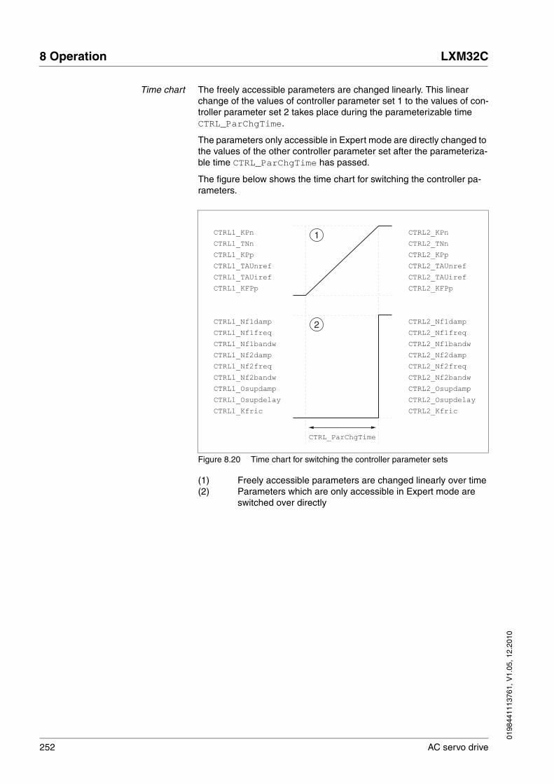
252 AC servo drive
8 Operation LXM32C
0198
4411
1376
1, V
1.05
, 12.
2010
Time chart The freely accessible parameters are changed linearly. This linear change of the values of controller parameter set 1 to the values of con-troller parameter set 2 takes place during the parameterizable time CTRL_ParChgTime.
The parameters only accessible in Expert mode are directly changed to the values of the other controller parameter set after the parameteriza-ble time CTRL_ParChgTime has passed.
The figure below shows the time chart for switching the controller pa-rameters.
Figure 8.20 Time chart for switching the controller parameter sets
(1) Freely accessible parameters are changed linearly over time(2) Parameters which are only accessible in Expert mode are
switched over directly
CTRL1_Nf1damp
CTRL1_Nf1freq
CTRL1_Nf1bandw
CTRL1_Nf2damp
CTRL1_Nf2freq
CTRL1_Nf2bandw
CTRL1_Osupdamp
CTRL1_Osupdelay
CTRL1_Kfric
CTRL_ParChgTime
CTRL1_KPn
CTRL1_TNn
CTRL1_KPp
CTRL1_TAUnref
CTRL1_TAUiref
CTRL1_KFPp
CTRL2_Nf1damp
CTRL2_Nf1freq
CTRL2_Nf1bandw
CTRL2_Nf2damp
CTRL2_Nf2freq
CTRL2_Nf2bandw
CTRL2_Osupdamp
CTRL2_Osupdelay
CTRL2_Kfric
CTRL2_KPn
CTRL2_TNn
CTRL2_KPp
CTRL2_TAUnref
CTRL2_TAUiref
CTRL2_KFPp
1
2

0198
4411
1376
1, V
1.05
, 12.
2010
LXM32C 8 Operation
AC servo drive 253
Parameter nameHMI menuHMI name
Description UnitMinimum valueFactory settingMaximum value
Data typeR/WPersistentExpert
Parameter address via fieldbus
CLSET_ParSwiCond
Condition for parameter set switching
0 / None Or Digital Input: None or digital input function selected1 / Inside Position Deviation: Inside posi-tion deviation (value definition in parameter CLSET_p_DiffWin)2 / Below Reference Velocity: Below refer-ence velocity (value definition in parameter CLSET_v_Threshol)3 / Below Actual Velocity: Below actual velocity (value definition in parameter CLSET_v_Threshol)
In the case of parameter set switching, the values of the following parameters are changed gradually:- CTRL_KPn- CTRL_TNn- CTRL_KPp- CTRL_TAUnref- CTRL_TAUiref- CTRL_KFPp
The following parameters are changed immediately after the time for parameter set switching (CTRL_ParChgTime):- CTRL_Nf1damp- CTRL_Nf1freq- CTRL_Nf1bandw- CTRL_Nf2damp- CTRL_Nf2freq- CTRL_Nf2bandw- CTRL_Osupdamp- CTRL_Osupdelay- CTRL_Kfric
Changed settings become active immedi-ately.
-003
UINT16R/Wper.-
Modbus 4404
CLSET_p_DiffWin_usr
Position deviation for parameter set switch-ing
If the position deviation of the position con-troller is less than the value of this parame-ter, the controller parameter set 2 is used. Otherwise, controller parameter set 1 is used.
The minimum value, the factory setting and the maximum value depend on the scaling factor
Changed settings become active immedi-ately.
usr_p01642147483647
INT32R/Wper.-
Modbus 4426

254 AC servo drive
8 Operation LXM32C
0198
4411
1376
1, V
1.05
, 12.
2010
CLSET_p_DiffWin Position deviation for parameter set switch-ing
If the position deviation of the position con-troller is less than the value of this parame-ter, the controller parameter set 2 is used. Otherwise, controller parameter set 1 is used.
The parameter CLSET_p_DiffWin_usr allows you to enter the value in user-defined units.
In increments of 0.0001 revolution.
Changed settings become active immedi-ately.
revolution0.00000.01002.0000
UINT16R/Wper.-
Modbus 4408
CLSET_v_Threshol
Velocity threshold for parameter set switch-ing
If the reference velocity or the actual velocity are less than the value of this parameter, the controller parameter set 2 is used. Other-wise, controller parameter set 1 is used.
Changed settings become active immedi-ately.
usr_v0502147483647
UINT32R/Wper.-
Modbus 4410
CLSET_winTime Time window for parameter set switching
Value 0: Window monitoring deactivated.Value >0: Window time for the parameters CLSET_v_Threshol and CLSET_p_DiffWin.
Changed settings become active immedi-ately.
ms001000
UINT16R/Wper.-
Modbus 4406
CTRL_ParChgTime Period of time for parameter switching
In the case of parameter set switching, the values of the following parameters are changed gradually:- CTRL_KPn- CTRL_TNn- CTRL_KPp- CTRL_TAUnref- CTRL_TAUiref- CTRL_KFPp
Such a parameter switching can be caused by - change of the active controller parameter set- change of the global gain- change of any of the parameters listed above- switching off the integral term of the velocity controller
Changed settings become active immedi-ately.
ms002000
UINT16R/Wper.-
Modbus 4392
Parameter nameHMI menuHMI name
Description UnitMinimum valueFactory settingMaximum value
Data typeR/WPersistentExpert
Parameter address via fieldbus

0198
4411
1376
1, V
1.05
, 12.
2010
LXM32C 8 Operation
AC servo drive 255
8.5.4.8 Copying a controller parameter set
The parameter CTRL_ParSetCopy allows you to copy the values of controller parameter set 1 to controller parameter set 2 or the values of controller parameter set 2 to controller parameter set 1.
8.5.4.9 Deactivating the integral term
The integral term of the velocity controller can be deactivated via the sig-nal input function "Velocity Controller Integral Off". If the integral term is deactivated, the integral action time of the velocity controller (CTRL1_TNn and CTRL2_TNn) is implicitly and gradually reduced to zero. The time it takes to reduce the value to zero depends on the pa-rameter CTRL_ParChgTime. In the case of vertical axes, the integral term is needed to reduce position deviations during standstill.
Parameter nameHMI menuHMI name
Description UnitMinimum valueFactory settingMaximum value
Data typeR/WPersistentExpert
Parameter address via fieldbus
CTRL_ParSetCopy Controller parameter set copying
Value 1: Copy controller parameter set 1 to set 2Value 2: Copy controller parameter set 2 to set 1
If parameter set 2 copied to parameter set 1, the parameter CTRL_GlobGain is set to 100%.
Changed settings become active immedi-ately.
-0.0-0.2
UINT16R/W--
Modbus 4396
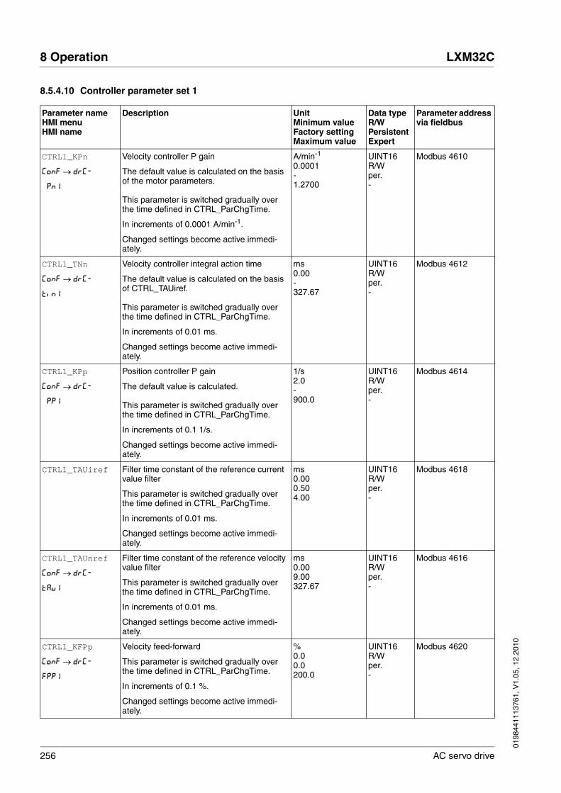
256 AC servo drive
8 Operation LXM32C
0198
4411
1376
1, V
1.05
, 12.
2010
8.5.4.10 Controller parameter set 1
Parameter nameHMI menuHMI name
Description UnitMinimum valueFactory settingMaximum value
Data typeR/WPersistentExpert
Parameter address via fieldbus
CTRL1_KPn
ConF → drC-
Pn1
Velocity controller P gain
The default value is calculated on the basis of the motor parameters.
This parameter is switched gradually over the time defined in CTRL_ParChgTime.
In increments of 0.0001 A/min-1.
Changed settings become active immedi-ately.
A/min-1
0.0001-1.2700
UINT16R/Wper.-
Modbus 4610
CTRL1_TNn
ConF → drC-
tin1
Velocity controller integral action time
The default value is calculated on the basis of CTRL_TAUiref.
This parameter is switched gradually over the time defined in CTRL_ParChgTime.
In increments of 0.01 ms.
Changed settings become active immedi-ately.
ms0.00-327.67
UINT16R/Wper.-
Modbus 4612
CTRL1_KPp
ConF → drC-
PP1
Position controller P gain
The default value is calculated.
This parameter is switched gradually over the time defined in CTRL_ParChgTime.
In increments of 0.1 1/s.
Changed settings become active immedi-ately.
1/s2.0-900.0
UINT16R/Wper.-
Modbus 4614
CTRL1_TAUiref Filter time constant of the reference current value filter
This parameter is switched gradually over the time defined in CTRL_ParChgTime.
In increments of 0.01 ms.
Changed settings become active immedi-ately.
ms0.000.504.00
UINT16R/Wper.-
Modbus 4618
CTRL1_TAUnref
ConF → drC-
tAu1
Filter time constant of the reference velocity value filter
This parameter is switched gradually over the time defined in CTRL_ParChgTime.
In increments of 0.01 ms.
Changed settings become active immedi-ately.
ms0.009.00327.67
UINT16R/Wper.-
Modbus 4616
CTRL1_KFPp
ConF → drC-
FPP1
Velocity feed-forward
This parameter is switched gradually over the time defined in CTRL_ParChgTime.
In increments of 0.1 %.
Changed settings become active immedi-ately.
%0.00.0200.0
UINT16R/Wper.-
Modbus 4620

0198
4411
1376
1, V
1.05
, 12.
2010
LXM32C 8 Operation
AC servo drive 257
CTRL1_Nf1damp Notch filter 1: Damping
In increments of 0.1 %.
Changed settings become active immedi-ately.
%55.090.099.0
UINT16R/Wper.expert
Modbus 4624
CTRL1_Nf1freq Notch filter 1: Frequency
The filter is switched off at a value of 15000.
In increments of 0.1 Hz.
Changed settings become active immedi-ately.
Hz50.01500.01500.0
UINT16R/Wper.expert
Modbus 4626
CTRL1_Nf1bandw Notch filter 1: Bandwidth
Definition of bandwidth: 1 - Fb/F0
In increments of 0.1 %.
Changed settings become active immedi-ately.
%1.070.090.0
UINT16R/Wper.expert
Modbus 4628
CTRL1_Nf2damp Notch filter 2: Damping
In increments of 0.1 %.
Changed settings become active immedi-ately.
%55.090.099.0
UINT16R/Wper.expert
Modbus 4630
CTRL1_Nf2freq Notch filter 2: Frequency
The filter is switched off at a value of 15000.
In increments of 0.1 Hz.
Changed settings become active immedi-ately.
Hz50.01500.01500.0
UINT16R/Wper.expert
Modbus 4632
CTRL1_Nf2bandw Notch filter 2: Bandwidth
Definition of bandwidth: 1 - Fb/F0
In increments of 0.1 %.
Changed settings become active immedi-ately.
%1.070.090.0
UINT16R/Wper.expert
Modbus 4634
CTRL1_Osupdamp Overshoot suppression filter: Damping
The filter is switched off at a value of 0.
In increments of 0.1 %.
Changed settings become active immedi-ately.
%0.00.050.0
UINT16R/Wper.expert
Modbus 4636
CTRL1_Osupdelay Overshoot suppression filter: Time delay
The filter is switched off at a value of 0.
In increments of 0.01 ms.
Changed settings become active immedi-ately.
ms0.000.0075.00
UINT16R/Wper.expert
Modbus 4638
CTRL1_Kfric Friction compensation: Gain
In increments of 0.01 Arms.
Changed settings become active immedi-ately.
Arms0.000.0010.00
UINT16R/Wper.expert
Modbus 4640
Parameter nameHMI menuHMI name
Description UnitMinimum valueFactory settingMaximum value
Data typeR/WPersistentExpert
Parameter address via fieldbus
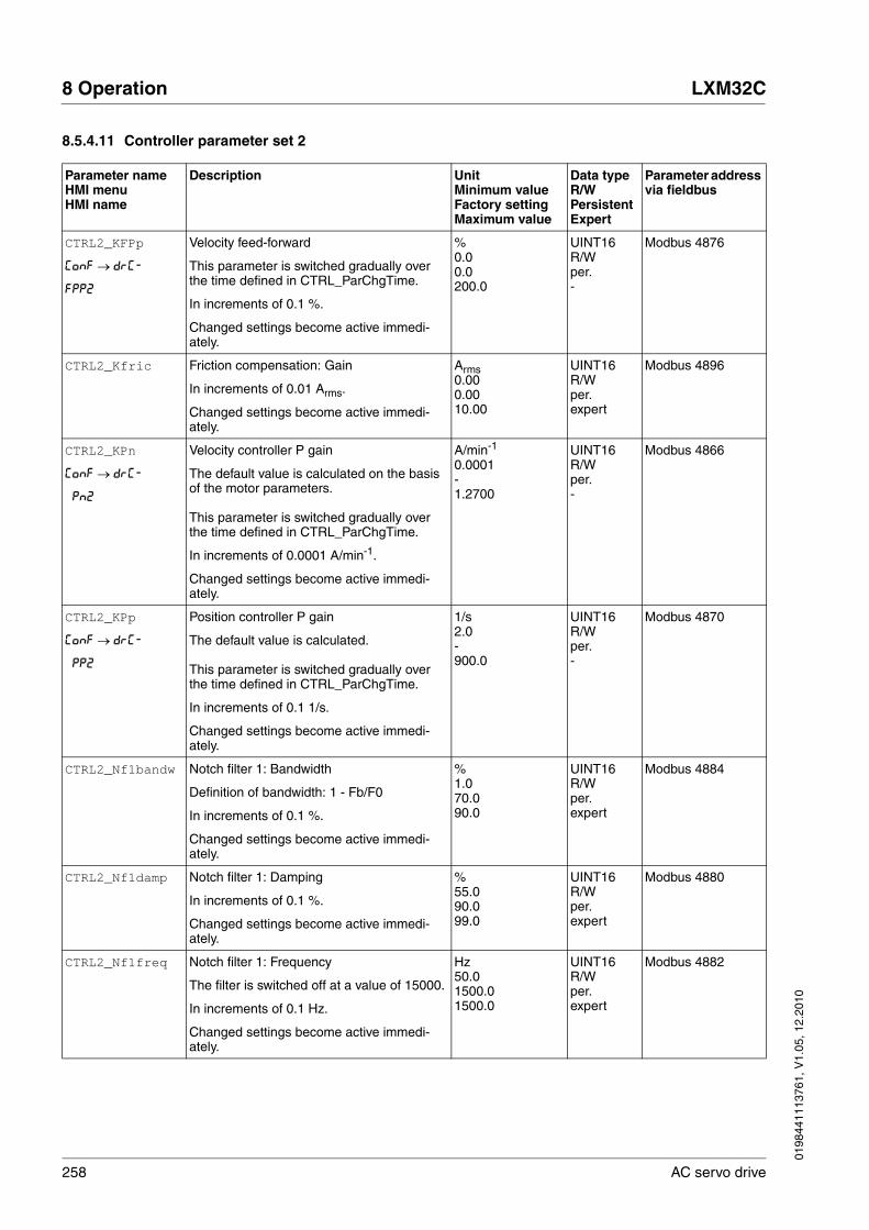
258 AC servo drive
8 Operation LXM32C
0198
4411
1376
1, V
1.05
, 12.
2010
8.5.4.11 Controller parameter set 2
Parameter nameHMI menuHMI name
Description UnitMinimum valueFactory settingMaximum value
Data typeR/WPersistentExpert
Parameter address via fieldbus
CTRL2_KFPp
ConF → drC-
FPP2
Velocity feed-forward
This parameter is switched gradually over the time defined in CTRL_ParChgTime.
In increments of 0.1 %.
Changed settings become active immedi-ately.
%0.00.0200.0
UINT16R/Wper.-
Modbus 4876
CTRL2_Kfric Friction compensation: Gain
In increments of 0.01 Arms.
Changed settings become active immedi-ately.
Arms0.000.0010.00
UINT16R/Wper.expert
Modbus 4896
CTRL2_KPn
ConF → drC-
Pn2
Velocity controller P gain
The default value is calculated on the basis of the motor parameters.
This parameter is switched gradually over the time defined in CTRL_ParChgTime.
In increments of 0.0001 A/min-1.
Changed settings become active immedi-ately.
A/min-1
0.0001-1.2700
UINT16R/Wper.-
Modbus 4866
CTRL2_KPp
ConF → drC-
PP2
Position controller P gain
The default value is calculated.
This parameter is switched gradually over the time defined in CTRL_ParChgTime.
In increments of 0.1 1/s.
Changed settings become active immedi-ately.
1/s2.0-900.0
UINT16R/Wper.-
Modbus 4870
CTRL2_Nf1bandw Notch filter 1: Bandwidth
Definition of bandwidth: 1 - Fb/F0
In increments of 0.1 %.
Changed settings become active immedi-ately.
%1.070.090.0
UINT16R/Wper.expert
Modbus 4884
CTRL2_Nf1damp Notch filter 1: Damping
In increments of 0.1 %.
Changed settings become active immedi-ately.
%55.090.099.0
UINT16R/Wper.expert
Modbus 4880
CTRL2_Nf1freq Notch filter 1: Frequency
The filter is switched off at a value of 15000.
In increments of 0.1 Hz.
Changed settings become active immedi-ately.
Hz50.01500.01500.0
UINT16R/Wper.expert
Modbus 4882
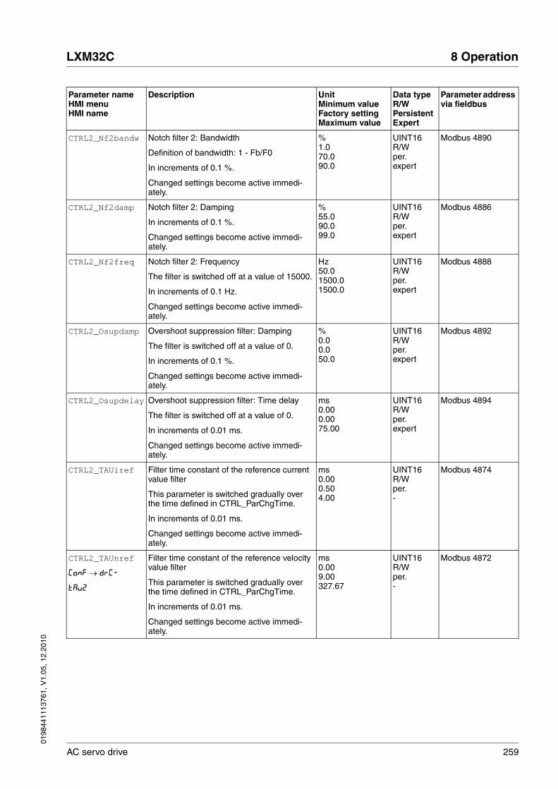
0198
4411
1376
1, V
1.05
, 12.
2010
LXM32C 8 Operation
AC servo drive 259
CTRL2_Nf2bandw Notch filter 2: Bandwidth
Definition of bandwidth: 1 - Fb/F0
In increments of 0.1 %.
Changed settings become active immedi-ately.
%1.070.090.0
UINT16R/Wper.expert
Modbus 4890
CTRL2_Nf2damp Notch filter 2: Damping
In increments of 0.1 %.
Changed settings become active immedi-ately.
%55.090.099.0
UINT16R/Wper.expert
Modbus 4886
CTRL2_Nf2freq Notch filter 2: Frequency
The filter is switched off at a value of 15000.
In increments of 0.1 Hz.
Changed settings become active immedi-ately.
Hz50.01500.01500.0
UINT16R/Wper.expert
Modbus 4888
CTRL2_Osupdamp Overshoot suppression filter: Damping
The filter is switched off at a value of 0.
In increments of 0.1 %.
Changed settings become active immedi-ately.
%0.00.050.0
UINT16R/Wper.expert
Modbus 4892
CTRL2_Osupdelay Overshoot suppression filter: Time delay
The filter is switched off at a value of 0.
In increments of 0.01 ms.
Changed settings become active immedi-ately.
ms0.000.0075.00
UINT16R/Wper.expert
Modbus 4894
CTRL2_TAUiref Filter time constant of the reference current value filter
This parameter is switched gradually over the time defined in CTRL_ParChgTime.
In increments of 0.01 ms.
Changed settings become active immedi-ately.
ms0.000.504.00
UINT16R/Wper.-
Modbus 4874
CTRL2_TAUnref
ConF → drC-
tAu2
Filter time constant of the reference velocity value filter
This parameter is switched gradually over the time defined in CTRL_ParChgTime.
In increments of 0.01 ms.
Changed settings become active immedi-ately.
ms0.009.00327.67
UINT16R/Wper.-
Modbus 4872
Parameter nameHMI menuHMI name
Description UnitMinimum valueFactory settingMaximum value
Data typeR/WPersistentExpert
Parameter address via fieldbus

260 AC servo drive
8 Operation LXM32C
0198
4411
1376
1, V
1.05
, 12.
2010
CTRL2_TNn
ConF → drC-
tin2
Velocity controller integral action time
The default value is calculated on the basis of CTRL_TAUiref.
This parameter is switched gradually over the time defined in CTRL_ParChgTime.
In increments of 0.01 ms.
Changed settings become active immedi-ately.
ms0.00-327.67
UINT16R/Wper.-
Modbus 4868
Parameter nameHMI menuHMI name
Description UnitMinimum valueFactory settingMaximum value
Data typeR/WPersistentExpert
Parameter address via fieldbus

0198
4411
1376
1, V
1.05
, 12.
2010
LXM32C 8 Operation
AC servo drive 261
8.5.5 Settings of parameter _DCOMstatus
The meaning of bit 11 of the parameter _DCOMstatus can be set.
The meaning of bit 11 can be set via the parameter DS402intLim.
Parameter nameHMI menuHMI name
Description UnitMinimum valueFactory settingMaximum value
Data typeR/WPersistentExpert
Parameter address via fieldbus
_DCOMstatus DriveCom status word
Bits 0 ... 3: Status bitsBit 4: Voltage enabledBits 5 ... 6: Status bitsBit 7: WarningBit 8: HALT request activeBit 9: RemoteBit 10: Target reachedBit 11: Internal limitBit 12: Operating mode-specificBit 13: x_errBit 14: x_endBit 15: ref_ok
The meaning of bit 11 can be set via the parameter DS402intLim.
----
UINT16R/---
Modbus 6916
Parameter nameHMI menuHMI name
Description UnitMinimum valueFactory settingMaximum value
Data typeR/WPersistentExpert
Parameter address via fieldbus
DS402intLim DS402 status word: Setting for bit 11 (inter-nal limit)
0 / None: Not used (reserved)1 / Current Below Threshold: Current threshold value2 / Velocity Below Threshold: Velocity threshold value3 / In Position Deviation Window: Position deviation window4 / In Velocity Deviation Window: Velocity deviation window9 / Hardware Limit Switch: Hardware limit switch10 / RMAC active or finished: Relative movement after capture is active or finished11 / Standstill Window: Standstill window
Setting for: - bit 11 of the parameter _DCOMstatus and - bit 10 of the parameters _motionStat and _actionStatus
Changed settings become active immedi-ately.
-0011
UINT16R/Wper.-
Modbus 6972
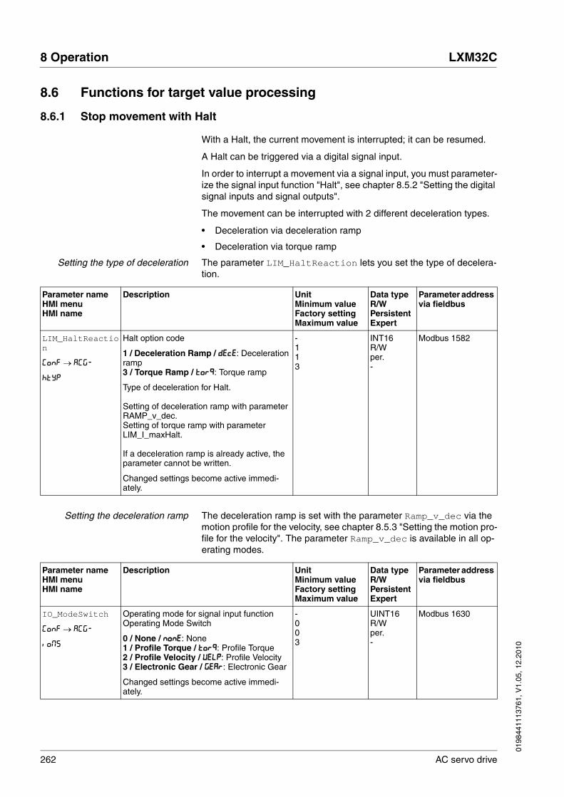
262 AC servo drive
8 Operation LXM32C
0198
4411
1376
1, V
1.05
, 12.
2010
8.6 Functions for target value processing
8.6.1 Stop movement with Halt
With a Halt, the current movement is interrupted; it can be resumed.
A Halt can be triggered via a digital signal input.
In order to interrupt a movement via a signal input, you must parameter-ize the signal input function "Halt", see chapter 8.5.2 "Setting the digital signal inputs and signal outputs".
The movement can be interrupted with 2 different deceleration types.
• Deceleration via deceleration ramp
• Deceleration via torque ramp
Setting the type of deceleration The parameter LIM_HaltReaction lets you set the type of decelera-tion.
Setting the deceleration ramp The deceleration ramp is set with the parameter Ramp_v_dec via the motion profile for the velocity, see chapter 8.5.3 "Setting the motion pro-file for the velocity". The parameter Ramp_v_dec is available in all op-erating modes.
Parameter nameHMI menuHMI name
Description UnitMinimum valueFactory settingMaximum value
Data typeR/WPersistentExpert
Parameter address via fieldbus
LIM_HaltReaction
ConF → ACG-
htyP
Halt option code
1 / Deceleration Ramp / dEcE: Deceleration ramp3 / Torque Ramp / torq: Torque ramp
Type of deceleration for Halt.
Setting of deceleration ramp with parameter RAMP_v_dec.Setting of torque ramp with parameter LIM_I_maxHalt.
If a deceleration ramp is already active, the parameter cannot be written.
Changed settings become active immedi-ately.
-113
INT16R/Wper.-
Modbus 1582
Parameter nameHMI menuHMI name
Description UnitMinimum valueFactory settingMaximum value
Data typeR/WPersistentExpert
Parameter address via fieldbus
IO_ModeSwitch
ConF → ACG-
ioMS
Operating mode for signal input function Operating Mode Switch
0 / None / nonE: None1 / Profile Torque / torq: Profile Torque2 / Profile Velocity / VELP: Profile Velocity3 / Electronic Gear / GEAr: Electronic Gear
Changed settings become active immedi-ately.
-003
UINT16R/Wper.-
Modbus 1630

0198
4411
1376
1, V
1.05
, 12.
2010
LXM32C 8 Operation
AC servo drive 263
Setting the torque ramp The parameter LIM_I_maxHalt lets you set the torque ramp.
RAMP_v_dec Deceleration of the motion profile for velocity
The minimum value depends on the operat-ing mode:
Operating modes with minimum value 1:Electronic Gear (velocity synchronization)Profile Velocity
Operating modes with minimum value 120:Jog
Writing the value 0 has no effect on the parameter.
Changed settings become active the next time the motor moves.
usr_a16002147483647
UINT32R/Wper.-
Modbus 1558
Parameter nameHMI menuHMI name
Description UnitMinimum valueFactory settingMaximum value
Data typeR/WPersistentExpert
Parameter address via fieldbus
Parameter nameHMI menuHMI name
Description UnitMinimum valueFactory settingMaximum value
Data typeR/WPersistentExpert
Parameter address via fieldbus
LIM_I_maxHalt
ConF → ACG-
hcur
Current value for Halt
This value is only limited by the minimum/maximum value range (no limitation of this value by motor/power stage).
In the case of a Halt, the actual current limit (_Imax_actual) is one of the following values (whichever is lowest):- LIM_I_maxHalt- M_I_max - PA_I_max
Further current reductions caused by I2t monitoring are also taken into account dur-ing a Halt.
Default: PA_I_max at 8 kHz PWM frequency and 230/480 V mains voltage
In increments of 0.01 Arms.
Changed settings become active immedi-ately.
Arms---
UINT16R/Wper.-
Modbus 4380
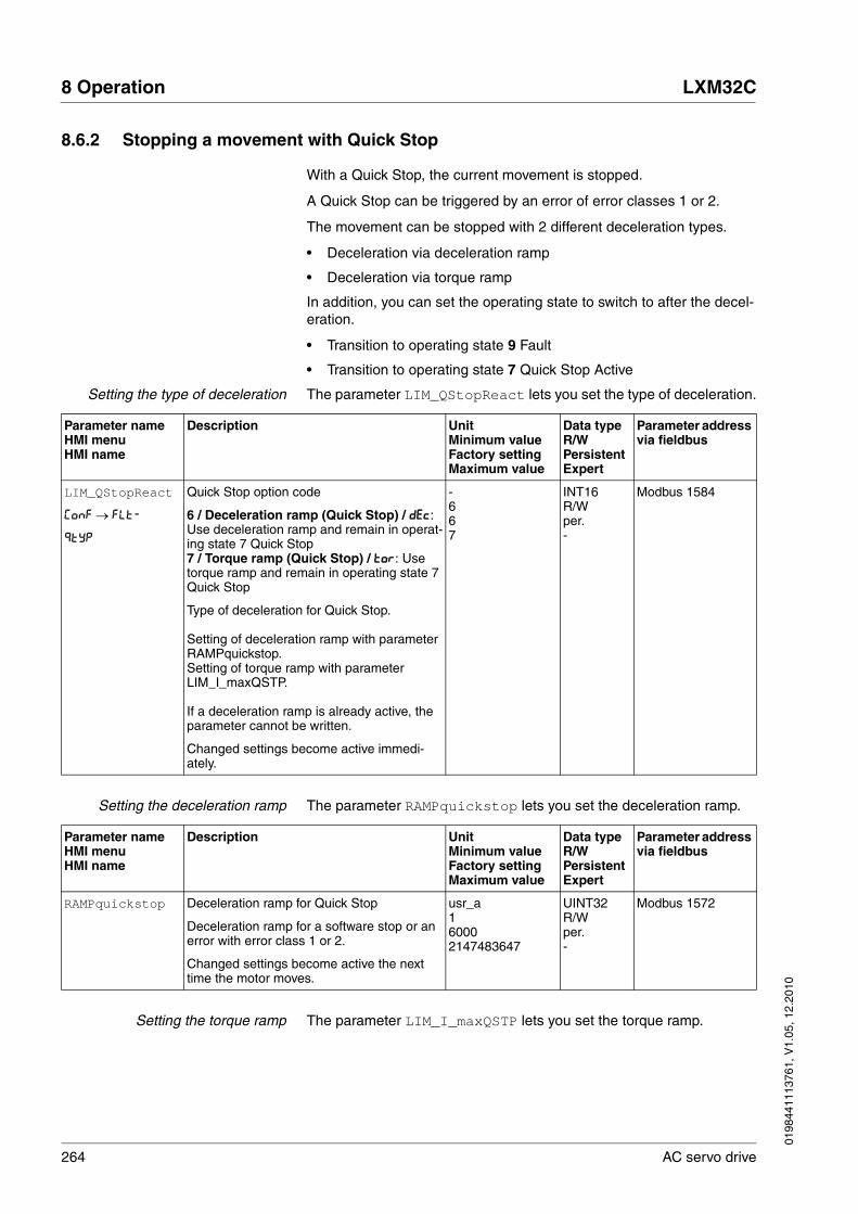
264 AC servo drive
8 Operation LXM32C
0198
4411
1376
1, V
1.05
, 12.
2010
8.6.2 Stopping a movement with Quick Stop
With a Quick Stop, the current movement is stopped.
A Quick Stop can be triggered by an error of error classes 1 or 2.
The movement can be stopped with 2 different deceleration types.
• Deceleration via deceleration ramp
• Deceleration via torque ramp
In addition, you can set the operating state to switch to after the decel-eration.
• Transition to operating state 9 Fault
• Transition to operating state 7 Quick Stop Active
Setting the type of deceleration The parameter LIM_QStopReact lets you set the type of deceleration.
Setting the deceleration ramp The parameter RAMPquickstop lets you set the deceleration ramp.
Setting the torque ramp The parameter LIM_I_maxQSTP lets you set the torque ramp.
Parameter nameHMI menuHMI name
Description UnitMinimum valueFactory settingMaximum value
Data typeR/WPersistentExpert
Parameter address via fieldbus
LIM_QStopReact
ConF → FLt-
qtyP
Quick Stop option code
6 / Deceleration ramp (Quick Stop) / dEc: Use deceleration ramp and remain in operat-ing state 7 Quick Stop7 / Torque ramp (Quick Stop) / tor: Use torque ramp and remain in operating state 7 Quick Stop
Type of deceleration for Quick Stop.
Setting of deceleration ramp with parameter RAMPquickstop.Setting of torque ramp with parameter LIM_I_maxQSTP.
If a deceleration ramp is already active, the parameter cannot be written.
Changed settings become active immedi-ately.
-667
INT16R/Wper.-
Modbus 1584
Parameter nameHMI menuHMI name
Description UnitMinimum valueFactory settingMaximum value
Data typeR/WPersistentExpert
Parameter address via fieldbus
RAMPquickstop Deceleration ramp for Quick Stop
Deceleration ramp for a software stop or an error with error class 1 or 2.
Changed settings become active the next time the motor moves.
usr_a160002147483647
UINT32R/Wper.-
Modbus 1572

0198
4411
1376
1, V
1.05
, 12.
2010
LXM32C 8 Operation
AC servo drive 265
8.6.3 Inverting the analog signal inputs
The evaluation of the analog signal inputs can be inverted via the digital signal inputs.
• The signal input function "Inversion AI1" inverts the signal evalua-tion of the analog signal input AI1.
• The signal input function "Inversion AI2" inverts the signal evalua-tion of the analog signal input AI2.
In order to invert the signal evaluation of the analog signal inputs, you must parameterize the signal input functions "Inversion AI1" or "Inver-sion AI2", see chapter 8.5.2 "Setting the digital signal inputs and signal outputs".
Availability The signal input functions are available in the following operating modes:
• Profile Torque
• Profile Velocity
Parameter nameHMI menuHMI name
Description UnitMinimum valueFactory settingMaximum value
Data typeR/WPersistentExpert
Parameter address via fieldbus
LIM_I_maxQSTP
ConF → FLt-
qcur
Current value for Quick Stop
This value is only limited by the minimum/maximum value range (no limitation of this value by motor/power stage).
In the case of a Quick Stop, the actual cur-rent limit (_Imax_actual) is one of the follow-ing values (whichever is lowest):- LIM_I_maxQSTP- M_I_max- PA_I_max
Further current reductions caused by I2t monitoring are also taken into account dur-ing a Quick Stop.
Default: PA_I_max at 8 kHz PWM frequency and 230/480 V mains voltage
In increments of 0.01 Arms.
Changed settings become active immedi-ately.
Arms---
UINT16R/Wper.-
Modbus 4378

266 AC servo drive
8 Operation LXM32C
0198
4411
1376
1, V
1.05
, 12.
2010
8.6.4 Limitation of the velocity via signal inputs
Limitation analog signal input The velocity can be limited via an analog signal input.
The parameters AI1_mode and AI2_mode let you select the type of us-age of the analog signal inputs.
� If you do not want to use the analog signal input, set the parameter AI1 to AI1_mode the value "Velocity Limitation".
If you do not want to use the analog signal input, set the parameter AI2 to AI2_mode the value "Velocity Limitation".
The parameters AI1_v_max and AI2_v_max are used to set the value of the limitation for a voltage value of +10V.
� If you want to use the analog signal input AI1, use the parameter AI1_v_max to set the value of the limitation for a voltage value of +10V.
If you want to use the analog signal input AI2, use the parameter AI2_v_max to set the value of the limitation for a voltage value of +10V.
Parameter nameHMI menuHMI name
Description UnitMinimum valueFactory settingMaximum value
Data typeR/WPersistentExpert
Parameter address via fieldbus
AI1_mode
ConF → i-o-
A1Mo
Analog 1: Type of usage
0 / None / nonE: No function1 / Target Velocity / SPdS: Target velocity for the velocity controller2 / Target Torque / trqS: Target torque for the current controller3 / Velocity Limitation / LSPd: Limitation of the velocity for the velocity controller4 / Torque Limitation / Ltrq: Limitation of the torque for the current controller
Setting can only be changed if power stage is disabled.
Changed settings become active the next time the power stage is enabled.
-014
UINT16R/Wper.-
Modbus 2332
AI2_mode
ConF → i-o-
A2Mo
Analog 2: Type of usage
0 / None / nonE: No function1 / Target Velocity / SPdS: Target velocity for the velocity controller2 / Target Torque / trqS: Target torque for the current controller3 / Velocity Limitation / LSPd: Limitation of the velocity for the velocity controller4 / Torque Limitation / Ltrq: Limitation of the torque for the current controller
Setting can only be changed if power stage is disabled.
Changed settings become active the next time the power stage is enabled.
-004
UINT16R/Wper.-
Modbus 2342

0198
4411
1376
1, V
1.05
, 12.
2010
LXM32C 8 Operation
AC servo drive 267
Limitation via digital signal input The velocity can be limited to a specific value via a digital signal input.
The parameter IO_v_limit lets you set the velocity limitation.
In order to limit the velocity via a digital signal input, you must parame-terize the signal input function "Velocity Limitation", see chapter 8.5.2 "Setting the digital signal inputs and signal outputs".
Parameter nameHMI menuHMI name
Description UnitMinimum valueFactory settingMaximum value
Data typeR/WPersistentExpert
Parameter address via fieldbus
AI1_v_max Analog 1: Limitation of velocity at 10 V
The maximum velocity is limited to the set-ting in CTRL_v_max.
Setting can only be changed if power stage is disabled.
Changed settings become active the next time the power stage is enabled.
usr_v130002147483647
UINT32R/Wper.-
Modbus 2336
AI2_v_max Analog 2: Limitation of velocity at 10 V
The maximum velocity is limited to the set-ting in CTRL_v_max.
Setting can only be changed if power stage is disabled.
Changed settings become active the next time the power stage is enabled.
usr_v130002147483647
UINT32R/Wper.-
Modbus 2346
Parameter nameHMI menuHMI name
Description UnitMinimum valueFactory settingMaximum value
Data typeR/WPersistentExpert
Parameter address via fieldbus
IO_v_limit Velocity limitation via input
A velocity limitation can be activated via a digital input.NOTE: In operating mode Profile Torque, the minimum velocity is internally limited to 100 min-1.
Changed settings become active immedi-ately.
usr_v1102147483647
UINT32R/Wper.-
Modbus 1596

268 AC servo drive
8 Operation LXM32C
0198
4411
1376
1, V
1.05
, 12.
2010
8.6.5 Limitation of the current via signal inputs
Limitation analog signal input The current can be limited via an analog signal input.
The parameters AI1_mode and AI2_mode let you select the type of us-age of the analog signal inputs.
� If you do not want to use the analog signal input, set the parameter AI1 to AI1_mode the value "Current Limitation".
If you do not want to use the analog signal input, set the parameter AI2 to AI2_mode the value "Current Limitation".
The parameters AI1_I_max and AI2_I_max are used to set the value of the limitation for a voltage value of +10V.
� If you want to use the analog signal input AI1, use the parameter AI1_I_max to set the value of the limitation for a voltage value of +10V.
If you want to use the analog signal input AI2, use the parameter AI2_I_max to set the value of the limitation for a voltage value of +10V.
Parameter nameHMI menuHMI name
Description UnitMinimum valueFactory settingMaximum value
Data typeR/WPersistentExpert
Parameter address via fieldbus
AI1_mode
ConF → i-o-
A1Mo
Analog 1: Type of usage
0 / None / nonE: No function1 / Target Velocity / SPdS: Target velocity for the velocity controller2 / Target Torque / trqS: Target torque for the current controller3 / Velocity Limitation / LSPd: Limitation of the velocity for the velocity controller4 / Torque Limitation / Ltrq: Limitation of the torque for the current controller
Setting can only be changed if power stage is disabled.
Changed settings become active the next time the power stage is enabled.
-014
UINT16R/Wper.-
Modbus 2332
AI2_mode
ConF → i-o-
A2Mo
Analog 2: Type of usage
0 / None / nonE: No function1 / Target Velocity / SPdS: Target velocity for the velocity controller2 / Target Torque / trqS: Target torque for the current controller3 / Velocity Limitation / LSPd: Limitation of the velocity for the velocity controller4 / Torque Limitation / Ltrq: Limitation of the torque for the current controller
Setting can only be changed if power stage is disabled.
Changed settings become active the next time the power stage is enabled.
-004
UINT16R/Wper.-
Modbus 2342

0198
4411
1376
1, V
1.05
, 12.
2010
LXM32C 8 Operation
AC servo drive 269
Limitation via digital signal input The current can be limited to a specific value via a digital signal input.
The parameter IO_I_limit lets you set the current limitation.
In order to limit the current via a digital signal input, you must parame-terize the signal input function "Current Limitation", see chapter 8.5.2 "Setting the digital signal inputs and signal outputs".
Parameter nameHMI menuHMI name
Description UnitMinimum valueFactory settingMaximum value
Data typeR/WPersistentExpert
Parameter address via fieldbus
AI1_I_max
ConF → i-o-
A1iL
Analog 1: Limitation of current at 10 V
In increments of 0.01 Arms.
Setting can only be changed if power stage is disabled.
Changed settings become active the next time the power stage is enabled.
Arms0.003.00300.00
UINT16R/Wper.-
Modbus 2334
AI2_I_max
ConF → i-o-
A2iL
Analog 2: Limitation of current at 10 V
In increments of 0.01 Arms.
Setting can only be changed if power stage is disabled.
Changed settings become active the next time the power stage is enabled.
Arms0.003.00300.00
UINT16R/Wper.-
Modbus 2344
Parameter nameHMI menuHMI name
Description UnitMinimum valueFactory settingMaximum value
Data typeR/WPersistentExpert
Parameter address via fieldbus
IO_I_limit
ConF → i-o-
iLiM
Current limitation via input
A current limit can be activated via a digital input.
In increments of 0.01 Arms.
Changed settings become active immedi-ately.
Arms0.000.20300.00
UINT16R/Wper.-
Modbus 1614

270 AC servo drive
8 Operation LXM32C
0198
4411
1376
1, V
1.05
, 12.
2010
8.6.6 Jerk limitation
Jerk limitation smoothes sudden acceleration changes to allow for smooth transitions with almost no jerking.
Figure 8.21 Jerk limitation
Availability Jerk limitation is available in the following operating modes.
• Jog
• Electronic Gear (position synchronization)(firmware version ≥V01.02 and parameter GEARjerklim)
Jerk limitation is activated and set via the parameter RAMP_v_jerk.
Operating mode Electronic Gear Jerk limitation is activated for the operating mode Electronic Gear by means of the parameter GEARjerklim.
t
v
Parameter nameHMI menuHMI name
Description UnitMinimum valueFactory settingMaximum value
Data typeR/WPersistentExpert
Parameter address via fieldbus
RAMP_v_jerk
ConF → drC-
JEr
Jerk limitation of the motion profile for veloc-ity
0 / Off / oFF: Off1 / 1 / 1: 1 ms2 / 2 / 2: 2 ms4 / 4 / 4: 4 ms8 / 8 / 8: 8 ms16 / 16 / 16: 16 ms32 / 32 / 32: 32 ms64 / 64 / 64: 64 ms128 / 128 / 128: 128 ms
Adjustments can only be made if the operat-ing mode is inactive (x_end=1).
Changed settings become active the next time the motor moves.
ms00128
UINT16R/Wper.-
Modbus 1562

0198
4411
1376
1, V
1.05
, 12.
2010
LXM32C 8 Operation
AC servo drive 271
8.6.7 Zero Clamp
The motor can be stopped via a digital signal input. The velocity of the motor must be below a parameterizable velocity value.
Availability The signal input function "Zero Clamp" is available in the following op-erating mode:
• Electronic Gear (velocity synchronization)
• Profile Velocity
Target velocities in the operating mode Profile Velocity and reference ve-locities in the operating mode Electronic Gear (Velocity Synchroniza-tion) that are below the parameterizable velocity value are interpreted as "Zero".
The signal input function "Zero Clamp" has a hysteresis of 20 %.
The parameter MON_v_zeroclamp lets you set the velocity value.
In order to stop the motor via a digital signal input, you must parameter-ize the signal input function "Zero Clamp", see chapter 8.5.2 "Setting the digital signal inputs and signal outputs".
Parameter nameHMI menuHMI name
Description UnitMinimum valueFactory settingMaximum value
Data typeR/WPersistentExpert
Parameter address via fieldbus
GEARjerklim
ConF → i-o-
GFiL
Activation of jerk filter processing
0 / Off / oFF: Jerk filter deactivated.1 / PosSyncOn / P_on: Jerk filter active in processing modes with position synchroniza-tion.
The jerk filter processing time must be acti-vated via parameter RAMP_v_jerk.
Setting can only be changed if power stage is disabled.
Changed settings become active immedi-ately.
Available as of software version V01.02.05.
-001
UINT16R/Wper.-
Modbus 9742
Parameter nameHMI menuHMI name
Description UnitMinimum valueFactory settingMaximum value
Data typeR/WPersistentExpert
Parameter address via fieldbus
MON_v_zeroclamp Velocity limit for Zero Clamp
A Zero Clamp operation is only possible if the reference velocity is below the Zero Clamp velocity limit.
Changed settings become active immedi-ately.
usr_v0102147483647
UINT32R/Wper.-
Modbus 1616
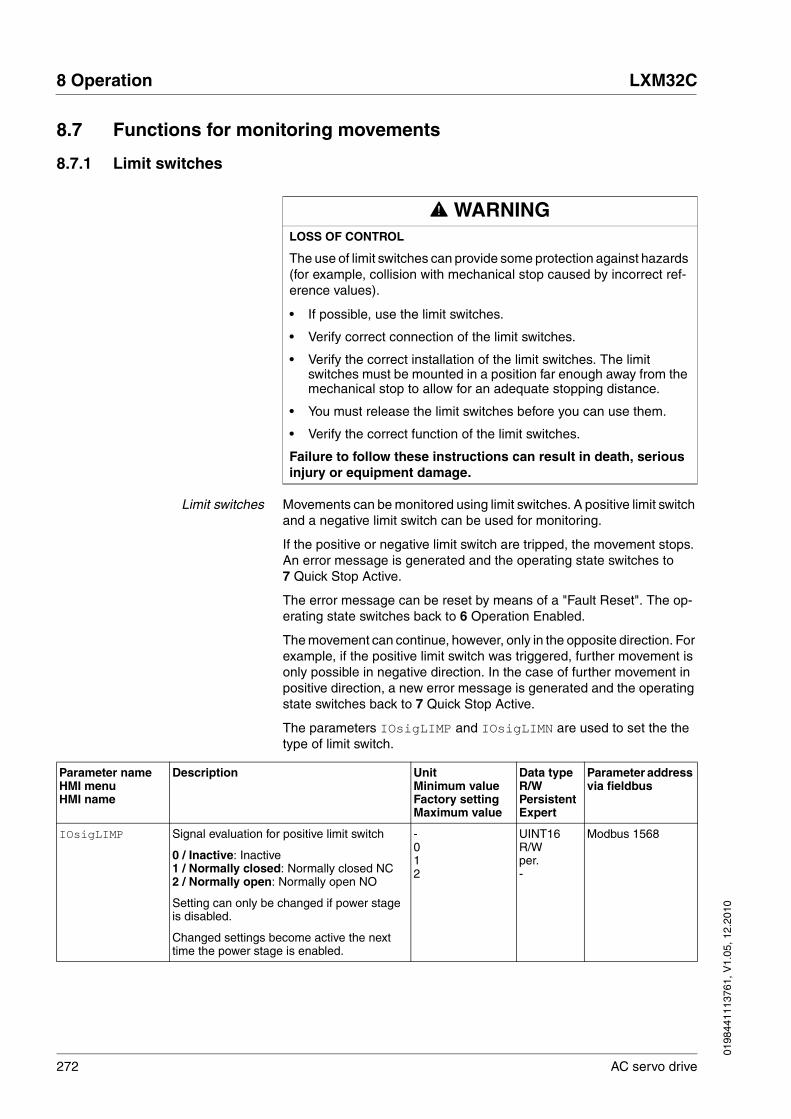
272 AC servo drive
8 Operation LXM32C
0198
4411
1376
1, V
1.05
, 12.
2010
8.7 Functions for monitoring movements
8.7.1 Limit switches
Limit switches Movements can be monitored using limit switches. A positive limit switch and a negative limit switch can be used for monitoring.
If the positive or negative limit switch are tripped, the movement stops. An error message is generated and the operating state switches to 7 Quick Stop Active.
The error message can be reset by means of a "Fault Reset". The op-erating state switches back to 6 Operation Enabled.
The movement can continue, however, only in the opposite direction. For example, if the positive limit switch was triggered, further movement is only possible in negative direction. In the case of further movement in positive direction, a new error message is generated and the operating state switches back to 7 Quick Stop Active.
The parameters IOsigLIMP and IOsigLIMN are used to set the the type of limit switch.
@ WARNINGLOSS OF CONTROL
The use of limit switches can provide some protection against hazards (for example, collision with mechanical stop caused by incorrect ref-erence values).
• If possible, use the limit switches.
• Verify correct connection of the limit switches.
• Verify the correct installation of the limit switches. The limit switches must be mounted in a position far enough away from the mechanical stop to allow for an adequate stopping distance.
• You must release the limit switches before you can use them.
• Verify the correct function of the limit switches.
Failure to follow these instructions can result in death, serious injury or equipment damage.
Parameter nameHMI menuHMI name
Description UnitMinimum valueFactory settingMaximum value
Data typeR/WPersistentExpert
Parameter address via fieldbus
IOsigLIMP Signal evaluation for positive limit switch
0 / Inactive: Inactive1 / Normally closed: Normally closed NC2 / Normally open: Normally open NO
Setting can only be changed if power stage is disabled.
Changed settings become active the next time the power stage is enabled.
-012
UINT16R/Wper.-
Modbus 1568

0198
4411
1376
1, V
1.05
, 12.
2010
LXM32C 8 Operation
AC servo drive 273
The signal input functions "Positive Limit Switch" and "Negative Limit Switch" must be parameterized, see chapter 8.5.2 "Setting the digital signal inputs and signal outputs".
If possible, use normally closed contacts so that a wire break can be signaled as an error.
IOsigLIMN Signal evaluation for negative limit switch
0 / Inactive: Inactive1 / Normally closed: Normally closed NC2 / Normally open: Normally open NO
Setting can only be changed if power stage is disabled.
Changed settings become active the next time the power stage is enabled.
-012
UINT16R/Wper.-
Modbus 1566
Parameter nameHMI menuHMI name
Description UnitMinimum valueFactory settingMaximum value
Data typeR/WPersistentExpert
Parameter address via fieldbus

274 AC servo drive
8 Operation LXM32C
0198
4411
1376
1, V
1.05
, 12.
2010
8.7.2 Load-dependent position deviation (following error)
The load-dependent position deviation is the difference between the ref-erence position and the actual position caused by the load.
Parameters are available to read the load-dependent position deviation during operation and the maximum position deviation reached so far.
The maximum permissible load-dependent position deviation can be parameterized. In addition, you can set the error class for a following er-ror.
Availability Monitoring of the load-dependent position deviation is available in the following operating modes:
• Jog
• Electronic Gear (position synchronization)
• Profile Position
• Homing
Reading the position deviation The following parameters let you read the current load-dependent posi-tion deviation in user-defined units or revolutions.
The following parameters let you read the maximum value of the load-dependent position deviation reached so far in user-defined units or rev-olutions.
Parameter nameHMI menuHMI name
Description UnitMinimum valueFactory settingMaximum value
Data typeR/WPersistentExpert
Parameter address via fieldbus
_p_dif_load_usr Current load-dependent position deviation between reference and actual position
The load-dependent position deviation is the difference between the reference position and the actual position caused by the load. This value is used for following error monitor-ing.
Available as of firmware version V01.05
usr_p-2147483648-2147483647
INT32R/---
Modbus 7724
_p_dif_load Current load-dependent position deviation between reference and actual position
The load-dependent position deviation is the difference between the reference position and the actual position caused by the load. This value is used for following error monitor-ing.
The parameter _p_dif_load_usr allows you to enter the value in user-defined units.
In increments of 0.0001 revolution.
revolution-214748.3648-214748.3647
INT32R/---
Modbus 7736

0198
4411
1376
1, V
1.05
, 12.
2010
LXM32C 8 Operation
AC servo drive 275
Setting the position deviation The following parameter lets you set the warning threshold for the max-imum load-dependent position deviation.
The following parameters let you set the following error threshold in user-defined units or revolutions for the maximum load-dependent posi-tion deviation.
Parameter nameHMI menuHMI name
Description UnitMinimum valueFactory settingMaximum value
Data typeR/WPersistentExpert
Parameter address via fieldbus
_p_dif_load_peak_usr
Maximum value of the load-dependent posi-tion deviation
This parameter contains the maximum load-dependent position deviation reached so far. A write access resets this value.
Available as of firmware version V01.05
Changed settings become active immedi-ately.
usr_p0-2147483647
INT32R/W--
Modbus 7722
_p_dif_load_peak
Maximum value of the load-dependent posi-tion deviation
This parameter contains the maximum load-dependent position deviation reached so far. A write access resets this value.
The parameter _p_dif_load_peak_usr allows you to enter the value in user-defined units..
In increments of 0.0001 revolution.
Changed settings become active immedi-ately.
revolution0.0000-429496.7295
UINT32R/W--
Modbus 7734
Parameter nameHMI menuHMI name
Description UnitMinimum valueFactory settingMaximum value
Data typeR/WPersistentExpert
Parameter address via fieldbus
MON_p_dif_warn Maximum load-dependent position deviation (warning)
100.0 % correspond to the maximum posi-tion deviation (following error) as specified by means of parameter MON_p_dif_load.
Changed settings become active immedi-ately.
%075100
UINT16R/Wper.-
Modbus 1618

276 AC servo drive
8 Operation LXM32C
0198
4411
1376
1, V
1.05
, 12.
2010
Setting the error class The following parameter lets you set the error response to an exces-sively high load-dependent position deviation (following error).
Parameter nameHMI menuHMI name
Description UnitMinimum valueFactory settingMaximum value
Data typeR/WPersistentExpert
Parameter address via fieldbus
MON_p_dif_load_usr
Maximum load-dependent position deviation (following error)
The load-dependent position deviation is the difference between the reference position and the actual position caused by the load.
The minimum value, the factory setting and the maximum value depend on the scaling factor.
Available as of firmware version V01.05
Changed settings become active immedi-ately.
usr_p1163842147483647
INT32R/Wper.-
Modbus 1660
MON_p_dif_load Maximum load-dependent position deviation (following error)
The load-dependent position deviation is the difference between the reference position and the actual position caused by the load.
The parameter MON_p_dif_load_usr allows you to enter the value in user-defined units.
In increments of 0.0001 revolution.
Changed settings become active immedi-ately.
revolution0.00011.0000200.0000
UINT32R/Wper.-
Modbus 1606
Parameter nameHMI menuHMI name
Description UnitMinimum valueFactory settingMaximum value
Data typeR/WPersistentExpert
Parameter address via fieldbus
ErrorResp_p_dif Error response to following error
1 / Error Class 1: Error class 12 / Error Class 2: Error class 23 / Error Class 3: Error class 3
Setting can only be changed if power stage is disabled.
Changed settings become active the next time the power stage is enabled.
-133
UINT16R/Wper.-
Modbus 1302

0198
4411
1376
1, V
1.05
, 12.
2010
LXM32C 8 Operation
AC servo drive 277
8.7.3 Motor standstill
It is possible to monitor whether the motor is at a standstill.
At a velocity of <10 min-1, the motor is at a standstill.
Figure 8.22 Motor standstill
The status is available via a signal output. In order to read the status, you must parameterize the signal output function "Motor Standstill", see chapter 8.5.2 "Setting the digital signal inputs and signal outputs".
0
v < 10
t
v
1
0

278 AC servo drive
8 Operation LXM32C
0198
4411
1376
1, V
1.05
, 12.
2010
8.7.4 Position deviation window
The position deviation window allows you to monitor whether the motor is within a parameterizable position deviation.
The position deviation is the difference between reference position and actual position.
The position deviation window comprises position deviation and moni-toring time.
Availability The position deviation window is available in the following operating modes.
• Jog
• Electronic Gear (position synchronization)
Monitoring
Figure 8.23 Position deviation window
The parameters MON_p_DiffWin_usr (MON_p_DiffWin) and MON_ChkTime specify the size of the window.
Status indication The status is available via a signal output. In order to read the status, you must parameterize the signal output function "In Position Deviation Win-dow", see chapter 8.5.2 "Setting the digital signal inputs and signal out-puts".
The parameter MON_ChkTime acts on the parameters MON_p_DiffWin_usr (MON_p_DiffWin), MON_v_DiffWin, MON_v_Threshold and MON_I_Threshold.
0
_p_difMON_ChkTime
MON_ChkTime
2 * MON_p_DiffWin_usr
(MON_p_DiffWin)
= 0
> 0
t
MON_ChkTime
1
0
1
0

0198
4411
1376
1, V
1.05
, 12.
2010
LXM32C 8 Operation
AC servo drive 279
Parameter nameHMI menuHMI name
Description UnitMinimum valueFactory settingMaximum value
Data typeR/WPersistentExpert
Parameter address via fieldbus
MON_p_DiffWin_usr
Monitoring of position deviation
The system checks whether the drive is within the defined deviation during the period set with MON_ChkTime. The status can be output via a parameteriza-ble output.
The minimum value, the factory setting and the maximum value depend on the scaling factor.
Available as of firmware version V01.05
Changed settings become active immedi-ately.
usr_p0162147483647
INT32R/Wper.-
Modbus 1662
MON_p_DiffWin Monitoring of position deviation
The system checks whether the drive is within the defined deviation during the period set with MON_ChkTime. The status can be output via a parameteriza-ble output.
The parameter MON_p_DiffWin_usr allows you to enter the value in user-defined units.
In increments of 0.0001 revolution.
Changed settings become active immedi-ately.
revolution0.00000.00100.9999
UINT16R/Wper.-
Modbus 1586
MON_ChkTime
ConF → i-o-
tthr
Monitoring of time window
Adjustment of a time for monitoring of posi-tion deviation, speed deviation, speed value and current value. If the monitored value is in the permissible range during the adjusted time, the monitoring function delivers a posi-tive result.The status can be output via a parameteriza-ble output.
Changed settings become active immedi-ately.
ms009999
UINT16R/Wper.-
Modbus 1594

280 AC servo drive
8 Operation LXM32C
0198
4411
1376
1, V
1.05
, 12.
2010
8.7.5 Velocity deviation window
The velocity deviation window allows you to monitor whether the motor is within a parameterizable velocity deviation.
The velocity deviation is the difference between the reference velocity and the actual velocity.
The velocity deviation window comprises velocity deviation and monitor-ing time.
Availability The velocity deviation window is available in the following operating modes.
• Jog
• Electronic Gear (velocity synchronization)
• Profile Velocity
Monitoring
Figure 8.24 Velocity deviation window
The parameters MON_v_DiffWin and MON_ChkTime specify the size of the window.
Status indication The status is available via a signal output. In order to read the status, you must parameterize the signal output function "In Velocity Deviation Win-dow", see chapter 8.5.2 "Setting the digital signal inputs and signal out-puts".
The parameter MON_ChkTime acts on the parameters MON_p_DiffWin_usr (MON_p_DiffWin), MON_v_DiffWin, MON_v_Threshold and MON_I_Threshold.
0
MON_ChkTime
2 * MON_v_DiffWin
= 0
> 0
t
v
MON_ChkTime
1
0
1
0
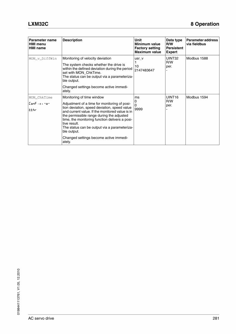
0198
4411
1376
1, V
1.05
, 12.
2010
LXM32C 8 Operation
AC servo drive 281
Parameter nameHMI menuHMI name
Description UnitMinimum valueFactory settingMaximum value
Data typeR/WPersistentExpert
Parameter address via fieldbus
MON_v_DiffWin Monitoring of velocity deviation
The system checks whether the drive is within the defined deviation during the period set with MON_ChkTime. The status can be output via a parameteriza-ble output.
Changed settings become active immedi-ately.
usr_v1102147483647
UINT32R/Wper.-
Modbus 1588
MON_ChkTime
ConF → i-o-
tthr
Monitoring of time window
Adjustment of a time for monitoring of posi-tion deviation, speed deviation, speed value and current value. If the monitored value is in the permissible range during the adjusted time, the monitoring function delivers a posi-tive result.The status can be output via a parameteriza-ble output.
Changed settings become active immedi-ately.
ms009999
UINT16R/Wper.-
Modbus 1594
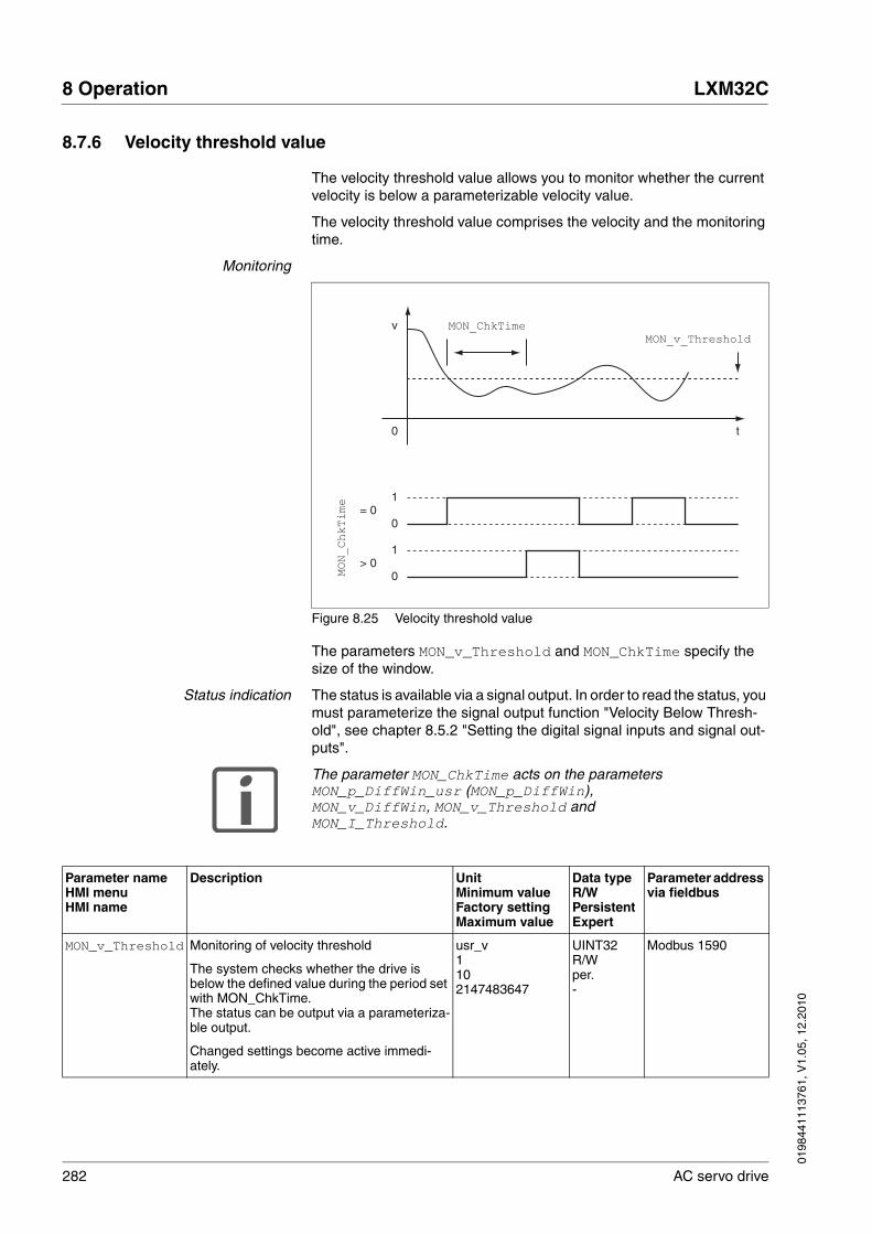
282 AC servo drive
8 Operation LXM32C
0198
4411
1376
1, V
1.05
, 12.
2010
8.7.6 Velocity threshold value
The velocity threshold value allows you to monitor whether the current velocity is below a parameterizable velocity value.
The velocity threshold value comprises the velocity and the monitoring time.
Monitoring
Figure 8.25 Velocity threshold value
The parameters MON_v_Threshold and MON_ChkTime specify the size of the window.
Status indication The status is available via a signal output. In order to read the status, you must parameterize the signal output function "Velocity Below Thresh-old", see chapter 8.5.2 "Setting the digital signal inputs and signal out-puts".
The parameter MON_ChkTime acts on the parameters MON_p_DiffWin_usr (MON_p_DiffWin), MON_v_DiffWin, MON_v_Threshold and MON_I_Threshold.
0
MON_ChkTime
MON_ChkTime
MON_v_Threshold
= 0
> 0
t
v
1
0
1
0
Parameter nameHMI menuHMI name
Description UnitMinimum valueFactory settingMaximum value
Data typeR/WPersistentExpert
Parameter address via fieldbus
MON_v_Threshold Monitoring of velocity threshold
The system checks whether the drive is below the defined value during the period set with MON_ChkTime. The status can be output via a parameteriza-ble output.
Changed settings become active immedi-ately.
usr_v1102147483647
UINT32R/Wper.-
Modbus 1590
0198
4411
1376
1, V
1.05
, 12.
2010
LXM32C 8 Operation
AC servo drive 283
MON_ChkTime
ConF → i-o-
tthr
Monitoring of time window
Adjustment of a time for monitoring of posi-tion deviation, speed deviation, speed value and current value. If the monitored value is in the permissible range during the adjusted time, the monitoring function delivers a posi-tive result.The status can be output via a parameteriza-ble output.
Changed settings become active immedi-ately.
ms009999
UINT16R/Wper.-
Modbus 1594
Parameter nameHMI menuHMI name
Description UnitMinimum valueFactory settingMaximum value
Data typeR/WPersistentExpert
Parameter address via fieldbus

284 AC servo drive
8 Operation LXM32C
0198
4411
1376
1, V
1.05
, 12.
2010
8.7.7 Current threshold value
The current threshold value allows you to monitor whether the current motor current is below a parameterizable current value.
The current threshold value comprises the current value and the moni-toring time.
Monitoring
Figure 8.26 Current threshold value
The parameters MON_I_Threshold and MON_ChkTime specify the size of the window.
Status indication The status is available via a signal output. In order to read the status, you must parameterize the signal output function "Current Below Thresh-old", see chapter 8.5.2 "Setting the digital signal inputs and signal out-puts".
The parameter MON_ChkTime acts on the parameters MON_p_DiffWin_usr (MON_p_DiffWin), MON_v_DiffWin, MON_v_Threshold and MON_I_Threshold.
0
MON_ChkTime
MON_ChkTime
MON_I_Threshold
= 0
> 0
t
I
1
0
1
0
Parameter nameHMI menuHMI name
Description UnitMinimum valueFactory settingMaximum value
Data typeR/WPersistentExpert
Parameter address via fieldbus
MON_I_Threshold
ConF → i-o-
ithr
Monitoring of current threshold
The system checks whether the drive is below the defined value during the period set with MON_ChkTime. The status can be output via a parameteriza-ble output.The parameter _Iq_act_rms is used as com-parison value.
In increments of 0.01 Arms.
Changed settings become active immedi-ately.
Arms0.000.20300.00
UINT16R/Wper.-
Modbus 1592

0198
4411
1376
1, V
1.05
, 12.
2010
LXM32C 8 Operation
AC servo drive 285
MON_ChkTime
ConF → i-o-
tthr
Monitoring of time window
Adjustment of a time for monitoring of posi-tion deviation, speed deviation, speed value and current value. If the monitored value is in the permissible range during the adjusted time, the monitoring function delivers a posi-tive result.The status can be output via a parameteriza-ble output.
Changed settings become active immedi-ately.
ms009999
UINT16R/Wper.-
Modbus 1594
Parameter nameHMI menuHMI name
Description UnitMinimum valueFactory settingMaximum value
Data typeR/WPersistentExpert
Parameter address via fieldbus

286 AC servo drive
8 Operation LXM32C
0198
4411
1376
1, V
1.05
, 12.
2010
8.8 Functions for monitoring internal device signals
8.8.1 Temperature monitoring
The power stage temperature the motor temperature are monitored in-ternally.
Power stage temperature The parameters _PS_T_current and _PS_T_max can be used to read the current temperature and the maximum temperature of the power stage.
The parameter _PS_T_warn contains as threshold value for a warning.
Motor temperature The parameters _M_T_current and _M_T_max can be used to read the current temperature and the maximum temperature of the motor.
Parameter nameHMI menuHMI name
Description UnitMinimum valueFactory settingMaximum value
Data typeR/WPersistentExpert
Parameter address via fieldbus
_PS_T_current
Mon
tPS
Current power stage temperature °C---
INT16R/---
Modbus 7200
_PS_T_warn Temperature warning threshold of power stage
°C---
INT16R/-per.-
Modbus 4108
_PS_T_max Maximum power stage temperature °C---
INT16R/-per.-
Modbus 4110
Parameter nameHMI menuHMI name
Description UnitMinimum valueFactory settingMaximum value
Data typeR/WPersistentExpert
Parameter address via fieldbus
_M_T_current Current motor temperature
No meaningful indication possible for switch-ing temperature sensors (see parameter M_TempType for temperature sensor type)
°C---
INT16R/---
Modbus 7202
_M_T_max Maximum temperature of motor °C---
INT16R/---
Modbus 3360
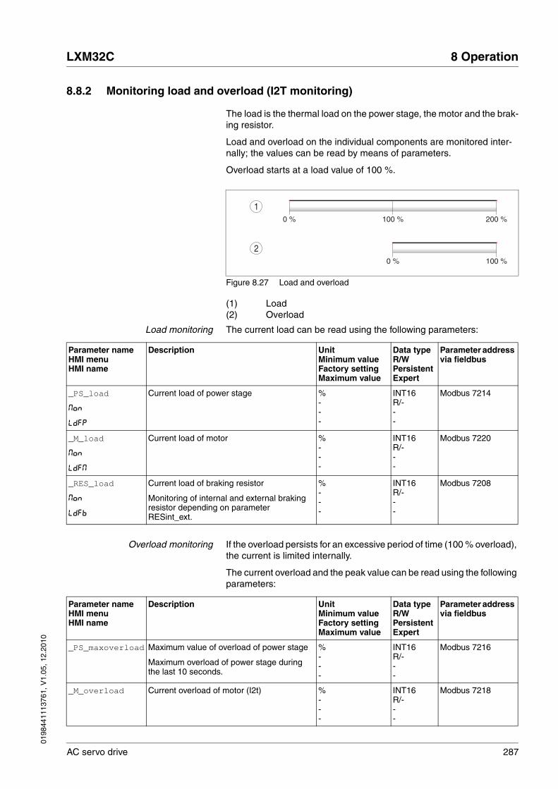
0198
4411
1376
1, V
1.05
, 12.
2010
LXM32C 8 Operation
AC servo drive 287
8.8.2 Monitoring load and overload (I2T monitoring)
The load is the thermal load on the power stage, the motor and the brak-ing resistor.
Load and overload on the individual components are monitored inter-nally; the values can be read by means of parameters.
Overload starts at a load value of 100 %.
Figure 8.27 Load and overload
(1) Load(2) Overload
Load monitoring The current load can be read using the following parameters:
Overload monitoring If the overload persists for an excessive period of time (100 % overload), the current is limited internally.
The current overload and the peak value can be read using the following parameters:
0 % 100 % 200 %
0 % 100 %
2
1
Parameter nameHMI menuHMI name
Description UnitMinimum valueFactory settingMaximum value
Data typeR/WPersistentExpert
Parameter address via fieldbus
_PS_load
Mon
LdFP
Current load of power stage %---
INT16R/---
Modbus 7214
_M_load
Mon
LdFM
Current load of motor %---
INT16R/---
Modbus 7220
_RES_load
Mon
LdFb
Current load of braking resistor
Monitoring of internal and external braking resistor depending on parameter RESint_ext.
%---
INT16R/---
Modbus 7208
Parameter nameHMI menuHMI name
Description UnitMinimum valueFactory settingMaximum value
Data typeR/WPersistentExpert
Parameter address via fieldbus
_PS_maxoverload Maximum value of overload of power stage
Maximum overload of power stage during the last 10 seconds.
%---
INT16R/---
Modbus 7216
_M_overload Current overload of motor (I2t) %---
INT16R/---
Modbus 7218

288 AC servo drive
8 Operation LXM32C
0198
4411
1376
1, V
1.05
, 12.
2010
_M_maxoverload Maximum value of overload of motor
Maximum overload of motor during the last 10 seconds.
%---
INT16R/---
Modbus 7222
_RES_overload Current overload of braking resistor (I2t)
Monitoring of internal and external braking resistor depending on parameter RESint_ext.
%---
INT16R/---
Modbus 7206
_RES_maxoverload
Maximum value of overload of braking resis-tor
Maximum overload of braking resistor during the last 10 seconds.
%---
INT16R/---
Modbus 7210
Parameter nameHMI menuHMI name
Description UnitMinimum valueFactory settingMaximum value
Data typeR/WPersistentExpert
Parameter address via fieldbus
0198
4411
1376
1, V
1.05
, 12.
2010
LXM32C 8 Operation
AC servo drive 289
8.8.3 Commutation monitoring
The device checks the plausibility of motor acceleration and effective motor torque in order to recognize uncontrolled movements and to sup-press them if required. The monitoring function is referred to as commu-tation monitoring.
If the motor accelerates for a period of more than 5 to 10 ms even though the drive control decelerates the motor with the maximum current set, commutation monitoring signals an uncontrolled motor movement.
The parameter MON_commutat lets you deactivate commutation mon-itoring.
@ WARNINGUNEXPECTED MOVEMENT
The risk of unexpected movements increases if monitoring functions are deactivated.
• Use the monitoring functions.
Failure to follow these instructions can result in death, serious injury or equipment damage.
Parameter nameHMI menuHMI name
Description UnitMinimum valueFactory settingMaximum value
Data typeR/WPersistentExpert
Parameter address via fieldbus
MON_commutat Commutation monitoring
0 / Off: Commutation monitoring off1 / On: Commutation monitoring on
Setting can only be changed if power stage is disabled.
Changed settings become active the next time the power stage is enabled.
-011
UINT16R/Wper.-
Modbus 1290
290 AC servo drive
8 Operation LXM32C
0198
4411
1376
1, V
1.05
, 12.
2010
8.8.4 Monitoring of mains phases
The mains phases are monitored internally.
The parameter ErrorResp_Flt_AC lets you set the error response to a missing mains phase for three-phase devices.
If the product is supplied via the DC bus, mains phase monitoring must be set to the mains voltage used.
The type of main phase monitoring is set by means of the parameter MON_MainsVolt.
CAUTIONDESTRUCTION CAUSED BY MISSING MAINS PHASE
If a mains phase for a three-phase product misses and the monitoring function is deactivated, this can cause overload and destruction of the product.
• Use the monitoring functions.
• Do not operate the product if a mains phase misses.
Failure to follow these instructions can result in equipment dam-age.
Parameter nameHMI menuHMI name
Description UnitMinimum valueFactory settingMaximum value
Data typeR/WPersistentExpert
Parameter address via fieldbus
ErrorResp_Flt_AC
Error response to missing mains phase
1 / Error Class 1: Error class 12 / Error Class 2: Error class 23 / Error Class 3: Error class 3
Setting can only be changed if power stage is disabled.
Changed settings become active the next time the power stage is enabled.
-123
UINT16R/Wper.-
Modbus 1300

0198
4411
1376
1, V
1.05
, 12.
2010
LXM32C 8 Operation
AC servo drive 291
Parameter nameHMI menuHMI name
Description UnitMinimum valueFactory settingMaximum value
Data typeR/WPersistentExpert
Parameter address via fieldbus
MON_MainsVolt Detection and monitoring of mains phases
0 / Automatic Mains Detection: Automatic detection and monitoring of mains voltage1 / DC-Bus Only (Mains 1~230 V / 3~480 V): DC bus supply only, corresponding to mains voltage 230 V (single-phase) or 480 V (three phases)2 / DC-Bus Only (Mains 1~115 V / 3~208 V): DC bus supply only, corresponding to mains voltage 115 V (single-phase) or 208 V (three phases)3 / Mains 1~230 V / 3~480 V: Mains voltage 230 V (single-phase) or 480 V (three phases)4 / Mains 1~115 V / 3~208 V: Mains voltage 115 V (single-phase) or 208 V (three phases)
Value 0: As soon as a mains voltage detected, the device automatically checks whether the mains voltage is 115 V or 230 V in the case of single-phase devices or 208 V or 400/480 V in the case of three-phase devices.
Values 1 ... 2: If the device is supplied only via the DC bus, the parameter has to be set to the voltage value corresponding to the mains voltage of the supplying device. There is no mains voltage monitoring.
Values 3 ... 4: If the mains voltage is not detected properly during start-up, the mains voltage to be used can be selected manually.
Setting can only be changed if power stage is disabled.
Changed settings become active the next time the power stage is enabled.
-004
UINT16R/Wper.expert
Modbus 1310

292 AC servo drive
8 Operation LXM32C
0198
4411
1376
1, V
1.05
, 12.
2010
8.8.5 Ground fault monitoring
When the power stage is enabled, the device monitors the motor phases for ground faults.
A ground fault of one or more motor phases is detected. A ground fault of the DC bus or the braking resistor is not detected.
CAUTIONDESTRUCTION CAUSED BY GROUND FAULTS
If the monitoring function is deactivated, the product may be de-stroyed by a ground fault.
• Use the monitoring functions.
• Avoid ground faults by wiring the product properly.
Failure to follow these instructions can result in equipment dam-age.
Parameter nameHMI menuHMI name
Description UnitMinimum valueFactory settingMaximum value
Data typeR/WPersistentExpert
Parameter address via fieldbus
MON_GroundFault Ground fault monitoring
0 / Off: Ground fault monitoring off1 / On: Ground fault monitoring on
In exceptional cases, deactivation may be necessary, for example:- Long motor cablesDeactivate ground fault monitoring if it responds in an unwanted way.
Changed settings become active the next time the product is switched on.
-011
UINT16R/Wper.expert
Modbus 1312

0198
4411
1376
1, V
1.05
, 12.
2010
LXM32C 9 Examples
AC servo drive 293
99 Examples
9.1 General information
The examples show some typical applications of the product. The ex-amples are intended to provide an overview; they are not exhaustive wir-ing plans.
Using the safety functions integrated in this product requires careful planning. See chapter 5.9 "Safety function STO ("Safe Torque Off")", page 77 for additional information.

294 AC servo drive
9 Examples LXM32C
0198
4411
1376
1, V
1.05
, 12.
2010
9.2 Example of operating mode Electronic Gear
Reference values are provided in the form of A/B signals.
Figure 9.1 Wiring example
(1) EMERGENCY STOP(2) PLC(3) See chapter 9 "Examples"(4) Commissioning accessories(5) Signal source for A/B signals
CN2 CN6
DICOM
DI0
DQCOM
AI1+
AI1-
SHLD
N
L1CN1
N/L2L1
DQ0
AI2+
AI2-
DQ1DQ2
DQ3
DQ4
DI1DI2DI3DI4DI5
CN4
18
"Gear ratio switch"
"In Position deviation window"
"Enable"
"Halt"
"Fault_Reset""Positive limit switch (LIMP)""Negative limit switch (LIMN)"
"Motor standstill"
"Selective error output"
"No fault"
"Active"
RS485
USB CN7
18
LXM32C
CN11BR+BR-
W
UV
CN10
CN3
18
A B
CN5
18
B
A
B
A
5V
2
5
4
CN
4 P
TOC
N5
PT
I
3
+
-24VDC
~
STO_A
24VSTO_B
0V
Pin 4Pin 5
Pin 7Pin 8
8
1
6
8
+
- LIMN
+
- LIMP
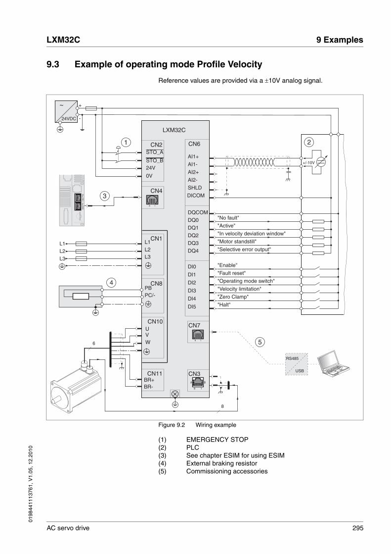
0198
4411
1376
1, V
1.05
, 12.
2010
LXM32C 9 Examples
AC servo drive 295
9.3 Example of operating mode Profile Velocity
Reference values are provided via a ±10V analog signal.
Figure 9.2 Wiring example
(1) EMERGENCY STOP(2) PLC(3) See chapter ESIM for using ESIM(4) External braking resistor(5) Commissioning accessories
CN11BR+BR-
+
-24VDC
~
CN2STO_A
24VSTO_B
0V
CN6
DICOM
DI0
DQCOM
AI1+
AI1-
SHLD
W
UV
CN10
CN1
L3
L1L2
L3
L2
L1
DQ0
AI2+
AI2-
DQ1
DQ2
DQ3
DQ4
DI1
DI2
DI3
DI4
DI5
CN3
18
A B
"Enable"
"Halt"
"Fault reset"
"Operating mode switch"
"Velocity limitation"
"Zero Clamp"
"In velocity deviation window"
"Motor standstill"
"Selective error output"
"No fault"
"Active"
+/-10V
2
CN8
PC/-PB
4
LXM32C
18
CN7
RS485
USB
5
CN4
18
CN
4 P
TOC
N5
PT
I
3
1
8
6

296 AC servo drive
9 Examples LXM32C
0198
4411
1376
1, V
1.05
, 12.
2010
0198
4411
1376
1, V
1.05
, 12.
2010
LXM32C 10 Diagnostics and troubleshooting
AC servo drive 297
1010 Diagnostics and troubleshooting
This chapter describes the various types of diagnostics and provides troubleshooting assistance.
10.1 Status request/status indication
Information on the product status is provided by:
• Integrated HMI
• Commissioning software
The error memory also contains a history of the last 10 errors.
Meaning of a warning message A warning alerts to a problem that was detected by a monitoring func-tion. The cause of a warning must be remedied.A warning belongs to error class 0 and does not cause a transition of the operating state.
Meaning of an error message An error is a deviation from the required value or state. Errors are sub-divided into different error classes.
Error class The product triggers an error response if an error occurs. Depending upon the severity of the error, the device responds in accordance with one of the following error classes:
Error class
Response Meaning
0 Warning A monitoring function has detected a problem. No interruption of the movement.
1 "Quick Stop" Motor stops with "Quick Stop", the power stage remains enabled.
2 "Quick Stop" with switch-off
Motor stops with "Quick Stop", the power stage is disabled after standstill has been achieved.
3 Fatal error The power stage is immediately disabled without stopping the motor first.
4 Uncontrolled operation
The power stage is immediately disabled without stopping the motor first. The error can only be reset by switching off the product.

298 AC servo drive
10 Diagnostics and troubleshooting LXM32C
0198
4411
1376
1, V
1.05
, 12.
2010
10.1.1 Diagnostics via the integrated HMI
The following illustration shows the status LEDs and the 7-segment dis-play of the integrated HMI
Figure 10.1 Status indication via the integrated HMI
Status LED "Fault" If the drive is in the operating state Fault, the "Fault" (1) status LED lights.
7-segment display The 7-segment display provides the user with information.
Warning messages If there are warnings (error class 0), the two dots to the right of the 7-seg-ment display (2) flash. Warnings are not directly displayed on the 7-seg-ment display in the form of an error number, bust must be explicitly queried by the user. See chapter 10.3.1 "Reading and acknowledging warnings", page 301 for additional information.
Error numbers Error numbers of errors belonging to error classes 1 to 4 on the one hand and the current operating state on the other hand are displayed al-ternately by the 7-segment display. See chapter 10.3.2 "Reading and acknowledging errors", page 302 for information on acknowledging er-rors via the integrated HMI.The meanings of the error numbers can be found in chapter 10.4.1 "Ta-ble of warnings and errors by range", page 304.
Messages on the integrated HMI The table below provides an overview of the messages that can be dis-played on the integrated HMI.
Fault Edit Value Unit
Op
Mon
Conf
1
2

0198
4411
1376
1, V
1.05
, 12.
2010
LXM32C 10 Diagnostics and troubleshooting
AC servo drive 299
Table 10.1 Table of the messages at the HMI
In addition to the messages as listed in Table 10.1, the integrated HMI displays information on the following:
• Error numbers (see chapter 10.4.1 "Table of warnings and errors by range", page 304)
• Menu labels (see chapter 7.3.2 "Menu structure", page 134)
• Parameter names (see chapter 11 "Parameters", page 321)
• Parameter values (for example, maximum current imax (IMAX))
10.1.2 Diagnostics via the commissioning software
See the information provided with the commissioning software for de-tails on how to display the device state via the commissioning software.
Message Description
Card Data on the memory card differs from data in the product. See chapter 7.8.1 "Data exchange with the memory card", page 187 for information on how to proceed.
dis The product is in the operating state 3 Switch On Disabled. There is no DC bus voltage or the inputs STO_A and STO_B have no current.
disp An external HMI is connected. The integrated HMI has no func-tion.
flt The display alternately shows Flt (FLT) and a 4-digit error number. See chapter 10.4.1 "Table of warnings and errors by range", page 304 for the meaning of the error number.
halt The motor is stopped, the power stage is enabled.
mot A new motor was detected. See chapter 10.3.3 "Acknowledging a motor change", page 303 for replacing a motor.
nrdy The product is not ready to switch on (operating state: 2 Not Ready To Switch On).
prot Parts of the integrated HMI were locked with the parameter HMIlocked.
rdy The power stage is ready to switch on.
run The product operates with the operating mode set.
stop The display alternately shows stop (STOP) and a 4-digit error number. See chapter 10.4.1 "Table of warnings and errors by range" for the meaning of the error number.
ulow Controller supply voltage during initialization not high enough.
8888 Undervoltage controller supply voltage.

300 AC servo drive
10 Diagnostics and troubleshooting LXM32C
0198
4411
1376
1, V
1.05
, 12.
2010
10.2 Error memory
General The error memory is an error history of the last 10 errors; it is not cleared even if the product is switched off. The error memory allows you to read and evaluate past events.
The following information on the events is stored:
• Error class
• Error number
• Motor current
• Number of switch-on cycles
• Additional error information (for example, parameter numbers)
• Product temperature
• Power stage temperature
• Time the error occurred (with reference to operating hours counter)
• DC bus voltage
• Velocity
• Number of Enable cycles after switch-on
• Time from Enable until occurrence of the error
The stored information relates to the situation at the point in time the er-ror occurred.
10.2.1 Reading the error memory via the commissioning software
See the information provided with the commissioning software for de-tails on how to read the error memory using the commissioning soft-ware.

0198
4411
1376
1, V
1.05
, 12.
2010
LXM32C 10 Diagnostics and troubleshooting
AC servo drive 301
10.3 Special menus at the integrated HMI
The following functions depend on the situation. They are only available in specific contexts.
10.3.1 Reading and acknowledging warnings
Procedure for reading and acknowledging warnings via the integrated HMI:
� A warning is active. The two dots to the right of the 7-segment dis-play flash.
� Remedy the cause of the warning.
� Press the navigation button and hold it down.
� The 7-segment display shows the error number of the warning.
� Release the navigation button.
� The 7-segment display shows fres.
� Press the navigation button to acknowledge the warning.
� The 7-segment display returns to the initial state.
Figure 10.2 Acknowledging warnings via the integrated HMI
(1) HMI displays a warning(2) Error number is displayed(3) Resetting the warning(4) Canceling, the warning remains in the memory
See chapter 10.4.1 "Table of warnings and errors by range", page 304, for detailed information on the warnings.
Fault Edit Value UnitOp
Mon
Conf
Fault Edit Value UnitOp
Mon
Conf
Fault Edit Value UnitOp
Mon
Conf
Fault Edit Value UnitOp
Mon
Conf
>1s
ESC
2
34
1

302 AC servo drive
10 Diagnostics and troubleshooting LXM32C
0198
4411
1376
1, V
1.05
, 12.
2010
10.3.2 Reading and acknowledging errors
Procedure for reading and acknowledging errors via the integrated HMI:
� The LED "Fault" is on. The 7-segment display alternately shows flt and an error number. An error of error classes 2 to 4 has occurred.
� Remedy the cause of the error.
� Press the navigation button.
� The 7-segment display shows fres.
� Press the navigation button to acknowledge the error.
� The product switches to operating state 4 Ready To Switch On.
Figure 10.3 Acknowledging errors via the integrated HMI
(1) HMI displays an error with error number
The meanings of the error numbers can be determined using the table in chapter 10.4.1 "Table of warnings and errors by range", page 304.
Fault Edit Value UnitOp
Mon
Conf
Fault Edit Value UnitOp
Mon
Conf
Fault Edit Value UnitOp
Mon
Conf
Fault Edit Value UnitOp
Mon
Conf
ESC
1
ESCESC

0198
4411
1376
1, V
1.05
, 12.
2010
LXM32C 10 Diagnostics and troubleshooting
AC servo drive 303
10.3.3 Acknowledging a motor change
Procedure for acknowledging a motor change via the integrated HMI:
� The 7-segment display shows mot.
� Press the navigation button.
� The 7-segment display shows save.
� Press the navigation button to save the new motor parameters to the EEPROM.
� The product switches to operating state 4 Ready To Switch On.
Figure 10.4 Acknowledging a motor change via the integrated HMI
(1) HMI displays that a replacement of a motor has been detect-ed.
(2) Canceling the saving process(3) Saving the new motor data and switching to operating state
4 Ready To Switch On.
Fault Edit Value UnitOp
Mon
Conf
Fault Edit Value UnitOp
Mon
Conf
Fault Edit Value UnitOp
Mon
Conf
ESC
ESC
2
3
1
2

304 AC servo drive
10 Diagnostics and troubleshooting LXM32C
0198
4411
1376
1, V
1.05
, 12.
2010
10.4 Troubleshooting
10.4.1 Table of warnings and errors by range
The table below summarizes the error numbers classified by range.
Error number not listed If the error number is not listed in the table below, the firmware version may be newer than the version of the manual or there may be a system error.
� Verify that you use the correct manual ( "About this manual")
� Verify that the wiring is EMC-compliant (5.1 "Electromagnetic com-patibility, EMC")
� Contact technical support (13.1 "Service address")
Error number Range
E 1xxx General
E 2xxx Overcurrent
E 3xxx Voltage
E 4xxx Temperature
E 5xxx Hardware
E 6xxx Software
E 7xxx Interface, wiring
E Axxx Motor movement
E Bxxx Communication

0198
4411
1376
1, V
1.05
, 12.
2010
LXM32C 10 Diagnostics and troubleshooting
AC servo drive 305
List of error numbers The table below provides an overview of the error numbers.
Error number
Error class
Description Cause Correctives
E 1100 - Parameter out of permissible range
The value entered was outside of the permissible value range for this parameter.
The entered value must be within the permissible value range.
E 1101 - Parameter does not exist Error signaled by parameter management: Parameter (index) does not exist.
Select a different parameter (index).
E 1102 - Parameter does not exist Error signaled by parameter management: Parameter (subindex) does not exist.
Select a different parameter (subindex).
E 1103 - Parameter write not permissi-ble (READ only)
Write access to read only parameter.
Write only to parameters that are not read-only.
E 1104 - Write access denied (no access authorization)
Parameter only accessible at expert level.
The write access level expert is required.
E 1106 - Command not allowed while power stage is active
Command not allowed while the power stage is enabled (operating state Operation Enabled or Quick Stop Active).
Disable the power stage and repeat the command.
E 1107 - Access via other interface blocked
Access occupied by another channel (for example: Com-missioning software is active and fieldbus access was tried at the same time).
Check the channel that blocks the access.
E 110B 3 Configuration error (additional info=Modbus register address)
Parameter _SigLatched Bit 30
Error detected during parame-ter check (for example, refer-ence velocity value for operating mode Profile Posi-tion is greater than maximum allowed velocity of drive).
Value in additional error infor-mation shows the Modbus reg-ister address of the parameter where the initialization error was detected.
E 110D 1 Basic configuration of drive required after factory setting
The "First Setup" (FSU) was not run at all or not completed.
Perform a First Setup.
E 110E - Parameter changed that requires a restart of the drive
Only displayed by the commis-sioning software.A parameter modification requires the drive to be switched off and on.
Restart the drive to activate the parameter functionality.See the chapter Parameters for the parameter that requires a restart of the drive.
E 1110 - Unknown file ID for upload or download
The specific type of device does not support this kind of file.
Verify that you have the correct device type or the correct con-figuration file.
E 1112 - Locking of configuration denied An external tool has tried to lock the configuration of the drive for upload or download. This may not work because another tool had already locked the configuration of the drive or the drive is in an oper-ating state that does not allow locking.
E 1114 4 Configuration download aborted
Parameter _SigLatched Bit 5
During a configuration down-load, a communication error or an error in the external tool occurred. The configuration was only partially transferred to the drive and might be incon-sistent now.
Switch the drive off/on and retry to download the configu-ration or reset the drive param-eters to their factory settings.
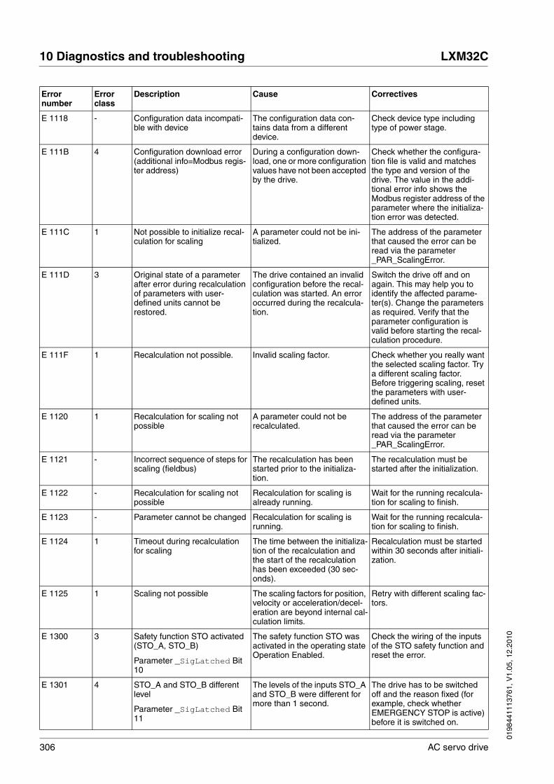
306 AC servo drive
10 Diagnostics and troubleshooting LXM32C
0198
4411
1376
1, V
1.05
, 12.
2010
E 1118 - Configuration data incompati-ble with device
The configuration data con-tains data from a different device.
Check device type including type of power stage.
E 111B 4 Configuration download error (additional info=Modbus regis-ter address)
During a configuration down-load, one or more configuration values have not been accepted by the drive.
Check whether the configura-tion file is valid and matches the type and version of the drive. The value in the addi-tional error info shows the Modbus register address of the parameter where the initializa-tion error was detected.
E 111C 1 Not possible to initialize recal-culation for scaling
A parameter could not be ini-tialized.
The address of the parameter that caused the error can be read via the parameter _PAR_ScalingError.
E 111D 3 Original state of a parameter after error during recalculation of parameters with user-defined units cannot be restored.
The drive contained an invalid configuration before the recal-culation was started. An error occurred during the recalcula-tion.
Switch the drive off and on again. This may help you to identify the affected parame-ter(s). Change the parameters as required. Verify that the parameter configuration is valid before starting the recal-culation procedure.
E 111F 1 Recalculation not possible. Invalid scaling factor. Check whether you really want the selected scaling factor. Try a different scaling factor. Before triggering scaling, reset the parameters with user-defined units.
E 1120 1 Recalculation for scaling not possible
A parameter could not be recalculated.
The address of the parameter that caused the error can be read via the parameter _PAR_ScalingError.
E 1121 - Incorrect sequence of steps for scaling (fieldbus)
The recalculation has been started prior to the initializa-tion.
The recalculation must be started after the initialization.
E 1122 - Recalculation for scaling not possible
Recalculation for scaling is already running.
Wait for the running recalcula-tion for scaling to finish.
E 1123 - Parameter cannot be changed Recalculation for scaling is running.
Wait for the running recalcula-tion for scaling to finish.
E 1124 1 Timeout during recalculation for scaling
The time between the initializa-tion of the recalculation and the start of the recalculation has been exceeded (30 sec-onds).
Recalculation must be started within 30 seconds after initiali-zation.
E 1125 1 Scaling not possible The scaling factors for position, velocity or acceleration/decel-eration are beyond internal cal-culation limits.
Retry with different scaling fac-tors.
E 1300 3 Safety function STO activated (STO_A, STO_B)
Parameter _SigLatched Bit 10
The safety function STO was activated in the operating state Operation Enabled.
Check the wiring of the inputs of the STO safety function and reset the error.
E 1301 4 STO_A and STO_B different level
Parameter _SigLatched Bit 11
The levels of the inputs STO_A and STO_B were different for more than 1 second.
The drive has to be switched off and the reason fixed (for example, check whether EMERGENCY STOP is active) before it is switched on.
Error number
Error class
Description Cause Correctives
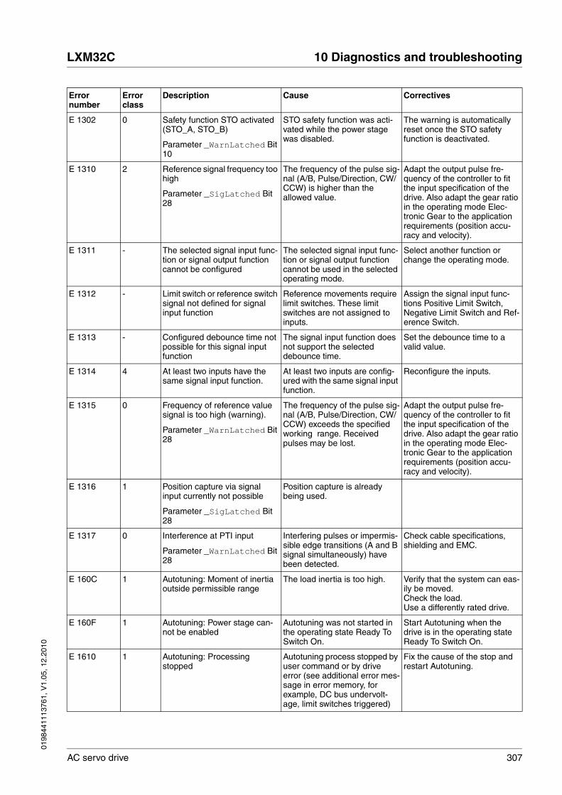
0198
4411
1376
1, V
1.05
, 12.
2010
LXM32C 10 Diagnostics and troubleshooting
AC servo drive 307
E 1302 0 Safety function STO activated (STO_A, STO_B)
Parameter _WarnLatched Bit 10
STO safety function was acti-vated while the power stage was disabled.
The warning is automatically reset once the STO safety function is deactivated.
E 1310 2 Reference signal frequency too high
Parameter _SigLatched Bit 28
The frequency of the pulse sig-nal (A/B, Pulse/Direction, CW/CCW) is higher than the allowed value.
Adapt the output pulse fre-quency of the controller to fit the input specification of the drive. Also adapt the gear ratio in the operating mode Elec-tronic Gear to the application requirements (position accu-racy and velocity).
E 1311 - The selected signal input func-tion or signal output function cannot be configured
The selected signal input func-tion or signal output function cannot be used in the selected operating mode.
Select another function or change the operating mode.
E 1312 - Limit switch or reference switch signal not defined for signal input function
Reference movements require limit switches. These limit switches are not assigned to inputs.
Assign the signal input func-tions Positive Limit Switch, Negative Limit Switch and Ref-erence Switch.
E 1313 - Configured debounce time not possible for this signal input function
The signal input function does not support the selected debounce time.
Set the debounce time to a valid value.
E 1314 4 At least two inputs have the same signal input function.
At least two inputs are config-ured with the same signal input function.
Reconfigure the inputs.
E 1315 0 Frequency of reference value signal is too high (warning).
Parameter _WarnLatched Bit 28
The frequency of the pulse sig-nal (A/B, Pulse/Direction, CW/CCW) exceeds the specified working range. Received pulses may be lost.
Adapt the output pulse fre-quency of the controller to fit the input specification of the drive. Also adapt the gear ratio in the operating mode Elec-tronic Gear to the application requirements (position accu-racy and velocity).
E 1316 1 Position capture via signal input currently not possible
Parameter _SigLatched Bit 28
Position capture is already being used.
E 1317 0 Interference at PTI input
Parameter _WarnLatched Bit 28
Interfering pulses or impermis-sible edge transitions (A and B signal simultaneously) have been detected.
Check cable specifications, shielding and EMC.
E 160C 1 Autotuning: Moment of inertia outside permissible range
The load inertia is too high. Verify that the system can eas-ily be moved.Check the load.Use a differently rated drive.
E 160F 1 Autotuning: Power stage can-not be enabled
Autotuning was not started in the operating state Ready To Switch On.
Start Autotuning when the drive is in the operating state Ready To Switch On.
E 1610 1 Autotuning: Processing stopped
Autotuning process stopped by user command or by drive error (see additional error mes-sage in error memory, for example, DC bus undervolt-age, limit switches triggered)
Fix the cause of the stop and restart Autotuning.
Error number
Error class
Description Cause Correctives

308 AC servo drive
10 Diagnostics and troubleshooting LXM32C
0198
4411
1376
1, V
1.05
, 12.
2010
E 1611 1 System error: Autotuning inter-nal write access
HALT is active and an Autotun-ing parameter is written. Occurs when Autotuning is started.
E 1613 1 Autotuning: Maximum permis-sible movement range exceeded
Parameter _SigLatched Bit 2
The motor exceeded the adjusted movement range dur-ing Autotuning.
Increase the movement range value or disable range monitor-ing by setting AT_DIS = 0.
E 1614 - Autotuning: Already active Autotuning has been started twice simultaneously or an Autotuning parameter is modi-fied during Autotuning (param-eter AT_dis and AT_dir).
Wait for Autotuning to finish before restarting Autotuning.
E 1615 - Autotuning: This parameter cannot be changed while Auto-tuning is active
Parameter AT_gain or AT_J are written during Autotuning.
Wait for Autotuning to finish before changing the parame-ter.
E 1617 1 Autotuning: Friction torque or load torque too great
The current limit has been reached (parameter CTRL_I_max).
Verify that the system can eas-ily be moved.Check the load.Use a differently rated drive.
E 1618 1 Autotuning: Optimization aborted
The internal Autotuning sequence has not been fin-ished (following error?).
Note the additional information provided in the error memory.
E 1619 - Autotuning: The velocity jump height in parameter AT_n_ref is too small
Parameter AT_n_ref < 2 * AT_n_tolerance.Checked only once at the first velocity jump.
Modify the parameter AT_n_ref or AT_n_tolerance to meet the desired condition.
E 1620 1 Autotuning: Load torque too high
Product rating is not suitable for the machine load.Detected machine inertia is too high compared to the inertia of the motor.
Reduce load, check rating.
E 1622 - Autotuning: Not possible to perform Autotuning
Autotuning can only be per-formed if no operating mode is active.
Terminate the active operating mode or disable the power stage.
E 1623 1 Autotuning: HALT request has stopped the autotuning proc-ess
Autotuning can only be per-formed if no operating mode is active.
Terminate the active operating mode or disable the power stage.
E 1A01 3 Motor has been changed
Parameter _SigLatched Bit 16
Detected motor type is differ-ent from previously detected motor.
Confirm the motor change.
E 1B04 2 Resolution of the encoder sim-ulation too high
Parameter _SigLatched Bit 30
Parameter CTRL_v_max too small or resolution of the encoder simulation too high.
Reduce the resolution of the encoder simulation or the max-imum velocity in parameter CTRL_v_max.
E 1B0C 3 Actual motor velocity too high.
E 2300 3 Power stage overcurrent
Parameter _SigLatched Bit 27
Motor short circuit and disa-bling of the power stage.Motor phases are inverted.
Check the motor power con-nection.
Error number
Error class
Description Cause Correctives

0198
4411
1376
1, V
1.05
, 12.
2010
LXM32C 10 Diagnostics and troubleshooting
AC servo drive 309
E 2301 3 Braking resistor overcurrent
Parameter _SigLatched Bit 27
Braking resistor short circuit. If you use the internal braking resistor, please contact Techni-cal Support.If you use an external braking resistor, check the wiring and the rating of the braking resis-tor.
E 3100 par. Mains power supply: Missing mains phase(s) or wrong mains voltage
Parameter _SigLatched Bit 15
Missing phase(s) for more than 50ms.Mains voltage is too low.Mains frequency is out of range.Mains voltage and parameter setting of MON_MainsVolt do not match (for example, mains voltage is 230V and MON_MainsVolt is set to 115V).
Verify that the values of the mains power supply network comply with the technical data.Check the settings of the parameter for reduced mains voltage.
E 3200 3 DC bus overvoltage
Parameter _SigLatched Bit 14
Excessive regeneration during braking.
Check deceleration ramp, check rating of drive and brak-ing resistor.
E 3201 3 DC bus undervoltage (shut-down threshold)
Parameter _SigLatched Bit 13
Power supply loss, poor power supply.
Check mains supply.
E 3202 2 DC bus undervoltage (Quick Stop threshold)
Parameter _SigLatched Bit 13
Power supply loss, poor power supply.
Check mains supply.
E 3206 0 DC bus undervoltage (warn-ing)
Parameter _WarnLatched Bit 13
Power supply loss, poor/incor-rect power supply.
Check mains supply.
E 3300 0 Maximum motor voltage is too low for the power stage used
The maximum motor voltage M_U_max is too low. The power stage supply voltage and the maximum motor volt-age do not match.
Use a motor with a higher max-imum voltage M_U_max. If this warning is ignored, the motor may be damaged.
E 4100 3 Power stage overtemperature
Parameter _SigLatched Bit 18
Transistors overtemperature: Ambient temperature is too high, fan is inoperative, dust.
Check the fan, improve the heat dissipation in the cabinet.
E 4101 0 Warning power stage overtem-perature
Parameter _WarnLatched Bit 18
Transistors overtemperature: Ambient temperature is too high, fan is inoperative, dust.
Check the fan, improve the heat dissipation in the cabinet.
E 4102 0 Power stage overload (I2t)
Parameter _WarnLatched Bit 30
The current has exceeded the nominal value for an extended period of time.
Check rating, reduce cycle time.
E 4200 3 Device overtemperature
Parameter _SigLatched Bit 18
Board overtemperature: Ambi-ent temperature is too high.
Check fan, improve the heat dissipation in the cabinet.
Error number
Error class
Description Cause Correctives

310 AC servo drive
10 Diagnostics and troubleshooting LXM32C
0198
4411
1376
1, V
1.05
, 12.
2010
E 4300 2 Motor overtemperature
Parameter _SigLatched Bit 17
Ambient temperature is too high.Duty cycle is too high.Motor not properly mounted (thermal isolation).Motor overload (power losses too high).
Check motor installation: The heat must be dissipated via the mounting surface. Reduce ambient temperature. Provide ventilation.
E 4301 0 Warning motor overtempera-ture
Parameter _WarnLatched Bit 17
Resistance of thermal sensor is too high; overload, ambient temp (see I2t).
Check motor installation: The heat must be dissipated via the mounting surface.
E 4302 0 Motor overload (I2t)
Parameter _WarnLatched Bit 31
The current has exceeded the nominal value for an extended period of time.
Verify that the system can eas-ily be moved.Check the load.Use a differently sized motor, if necessary.
E 4402 0 Warning: Braking resistor over-load (I2t > 75%)
Parameter _WarnLatched Bit 29
The braking resistor has been switched on for such a long period of time that 75% of its overload capability have been exceeded.
The regeneration energy is too high. Possible causes: The external loads are too high, the motor velocity is too high, the deceleration is too fast.
E 4403 par. Braking resistor overload (I2t > 100%)
The braking resistor is switched on for an excessively long period of time.
The regeneration energy is too high. Possible causes: The external loads are too high, the motor velocity is too high, the deceleration is too fast.
E 5101 0 Modbus power supply missing
E 5102 4 Motor encoder supply voltage
Parameter _SigLatched Bit 16
Encoder power supply is not within permissible range of 8V to 12V; there may be a hard-ware problem.
Replace the device.Contact Technical Support.
E 5200 4 Error at connection to motor encoder
Parameter _SigLatched Bit 16
Incorrect encoder cable or cable not connected, EMC.
Check the cable connection and the shield.
E 5201 4 Errors in motor encoder com-munication
Parameter _SigLatched Bit 16
Encoder error message: Com-munication error detected by the encoder itself.
Check the cable connection and the shield.
E 5202 4 Motor encoder is not sup-ported
Parameter _SigLatched Bit 16
Incompatible encoder type is connected.
Use genuine accessories.
E 5204 3 Connection to motor encoder lost
Parameter _SigLatched Bit 16
Encoder cable problems (com-munication has been inter-rupted).
Check the cable connection.
E 5206 0 Communication error in encoder
Parameter _WarnLatched Bit 16
Communication disturbed, EMC.
Check the connection, check the shielding on the EMC plate.
E 5207 1 Function is not supported The current hardware revision does not support the function.
Error number
Error class
Description Cause Correctives

0198
4411
1376
1, V
1.05
, 12.
2010
LXM32C 10 Diagnostics and troubleshooting
AC servo drive 311
E 5302 4 The motor requires a PWM fre-quency (16kHz) which the power stage does not support.
The connected motor only works with a PWM frequency of 16 kHz (motor nameplate entry). However, the power stage does not support this PWM frequency.
Use a motor that works with a PWM frequency of 8 kHz.
E 544C 4 System error: EEPROM is write-protected
Parameter _SigLatched Bit 29
E 5451 0 System error: No memory card available
Parameter _WarnLatched Bit 20
E 5452 2 System error: Data on memory card and device do not match
Parameter _SigLatched Bit 20
Different type of device.Different type of power stage.Data on memory card does not match firmware version of device.
E 5453 2 System error: Incompatible data on the memory card
Parameter _SigLatched Bit 20
E 5455 2 System error: Memory card not formatted
Parameter _SigLatched Bit 20
Update memory card via HMI command "dtoc" (drive-to-card).
E 5456 1 System error: Memory card is write-protected
Parameter _SigLatched Bit 20
The memory card has been write-protected.
Remove memory card or disa-ble write protection via HMI.
E 5506 1 Error during write access to safety module via fieldbus (additional info = detailed error number)
E 5600 3 Motor connection phase error
Parameter _SigLatched Bit 26
Missing motor phase. Check connection of motor phases.
E 5603 3 Commutation error
Parameter _SigLatched Bit 26
Wiring error of motor cable.Encoder signals are lost or subject to interference.The load torque is greater than the motor torque.The encoder EEPROM con-tains incorrect data (encoder phase offset is incorrect).Motor is not adjusted.
Check motor phases, check encoder wiring.Check and improve EMC situa-tion, check grounding and shielding.Resize the motor so it can withstand the load torque.Check the motor data.Contact Technical Support.
E 610D - Error in selection parameter Wrong parameter value selected.
Check the value to be written.
E 610E 4 System error: 24 VDC below undervoltage threshold for shutdown
Error number
Error class
Description Cause Correctives

312 AC servo drive
10 Diagnostics and troubleshooting LXM32C
0198
4411
1376
1, V
1.05
, 12.
2010
E 7100 4 System error: Invalid power stage data
Parameter _SigLatched Bit 30
Power stage data stored in device is corrupt (wrong CRC), error in internal memory data.
Contact technical support or replace the device.
E 7111 - Parameter cannot be changed because the external braking resistor is active.
An attempt is made to change one of the parameters RESext_ton, RESext_P or RESext_R even though the external braking resistor is active.
Verify that the external braking resistor is not active if one of the parameters RESext_ton, RESext_P or RESext_R has to be changed.
E 7112 2 No external braking resistor connected
External braking resistor acti-vated (Parameter RESint_ext), but no external resistor is detected.
Check wiring of the external braking resistor. Verify correct resistance.
E 7120 4 Invalid motor data
Parameter _SigLatched Bit 16
Motor data is corrupt (wrong CRC).
Contact technical support or replace the motor.
E 7121 2 System error: Errors in motor encoder communication
Parameter _SigLatched Bit 16
EMC, detailed information is included in the error memory that contains the error code of the encoder.
Contact technical support.
E 7122 4 Invalid motor data
Parameter _SigLatched Bit 30
Motor data stored in motor encoder is corrupt, error in internal memory data.
Contact technical support or replace the motor.
E 7124 4 System error: Motor encoder inoperative
Parameter _SigLatched Bit 16
Encoder signals internal error. Contact technical support or replace the motor.
E 712D 4 Electronic motor nameplate not found
Parameter _SigLatched Bit 16
Motor data is corrupt (wrong CRC).Motor without electronic motor nameplate (for example, SER motor)
Contact technical support or replace the motor.
E 7134 4 Incomplete motor configuration
Parameter _SigLatched Bit 16
E 7137 4 Error during the internal con-version of the motor configura-tion
Parameter _SigLatched Bit 16
E 7138 4 Parameter of the motor config-uration out of permissible range
Parameter _SigLatched Bit 16
E 7139 0 Encoder offset: Data segment in encoder is corrupt.
Error number
Error class
Description Cause Correctives
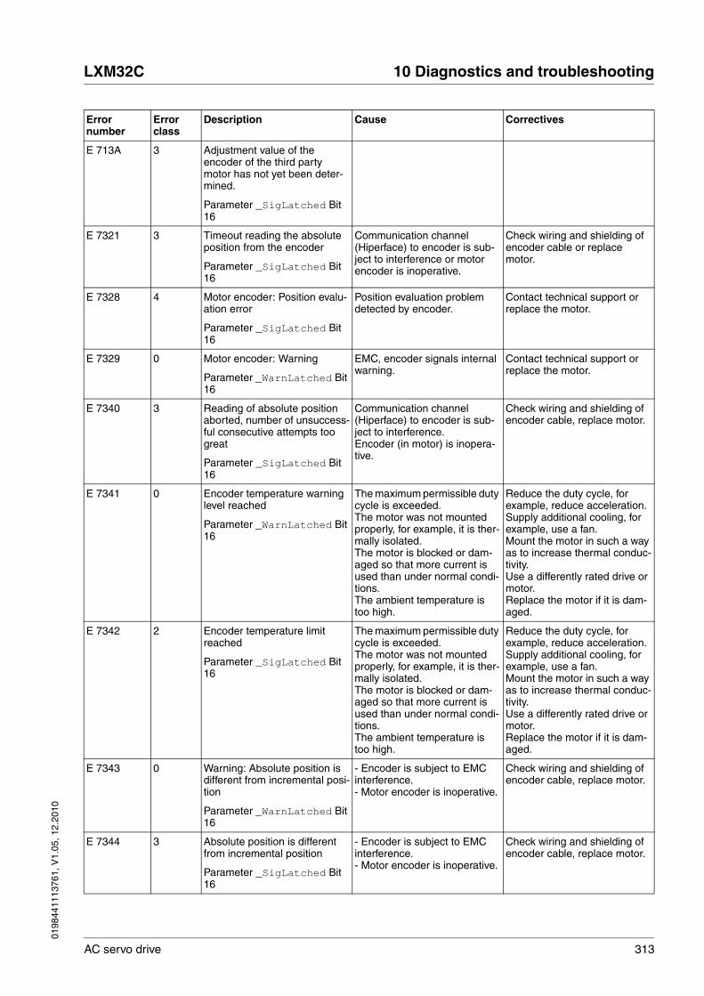
0198
4411
1376
1, V
1.05
, 12.
2010
LXM32C 10 Diagnostics and troubleshooting
AC servo drive 313
E 713A 3 Adjustment value of the encoder of the third party motor has not yet been deter-mined.
Parameter _SigLatched Bit 16
E 7321 3 Timeout reading the absolute position from the encoder
Parameter _SigLatched Bit 16
Communication channel (Hiperface) to encoder is sub-ject to interference or motor encoder is inoperative.
Check wiring and shielding of encoder cable or replace motor.
E 7328 4 Motor encoder: Position evalu-ation error
Parameter _SigLatched Bit 16
Position evaluation problem detected by encoder.
Contact technical support or replace the motor.
E 7329 0 Motor encoder: Warning
Parameter _WarnLatched Bit 16
EMC, encoder signals internal warning.
Contact technical support or replace the motor.
E 7340 3 Reading of absolute position aborted, number of unsuccess-ful consecutive attempts too great
Parameter _SigLatched Bit 16
Communication channel (Hiperface) to encoder is sub-ject to interference.Encoder (in motor) is inopera-tive.
Check wiring and shielding of encoder cable, replace motor.
E 7341 0 Encoder temperature warning level reached
Parameter _WarnLatched Bit 16
The maximum permissible duty cycle is exceeded.The motor was not mounted properly, for example, it is ther-mally isolated.The motor is blocked or dam-aged so that more current is used than under normal condi-tions.The ambient temperature is too high.
Reduce the duty cycle, for example, reduce acceleration.Supply additional cooling, for example, use a fan.Mount the motor in such a way as to increase thermal conduc-tivity.Use a differently rated drive or motor.Replace the motor if it is dam-aged.
E 7342 2 Encoder temperature limit reached
Parameter _SigLatched Bit 16
The maximum permissible duty cycle is exceeded.The motor was not mounted properly, for example, it is ther-mally isolated.The motor is blocked or dam-aged so that more current is used than under normal condi-tions.The ambient temperature is too high.
Reduce the duty cycle, for example, reduce acceleration.Supply additional cooling, for example, use a fan.Mount the motor in such a way as to increase thermal conduc-tivity.Use a differently rated drive or motor.Replace the motor if it is dam-aged.
E 7343 0 Warning: Absolute position is different from incremental posi-tion
Parameter _WarnLatched Bit 16
- Encoder is subject to EMC interference.- Motor encoder is inoperative.
Check wiring and shielding of encoder cable, replace motor.
E 7344 3 Absolute position is different from incremental position
Parameter _SigLatched Bit 16
- Encoder is subject to EMC interference.- Motor encoder is inoperative.
Check wiring and shielding of encoder cable, replace motor.
Error number
Error class
Description Cause Correctives

314 AC servo drive
10 Diagnostics and troubleshooting LXM32C
0198
4411
1376
1, V
1.05
, 12.
2010
E 734C 3 Error with quasi absolute posi-tion
Parameter _SigLatched Bit 16
The motor shaft may have been moved while the drive was shut down. A quasi abso-lute position has been detected that is not within the permissi-ble motor shaft deviation range.
If the quasi absolute function is active, only shut down the drive if the motor is at a standstill and do not move the motor shaft when the drive is off.
E 734D 0 Index pulse is not available for the encoder
Parameter _WarnLatched Bit 16
E 7500 0 RS485/Modbus: Overrun error
Parameter _WarnLatched Bit 5
EMC; cabling problem. Check cables.
E 7501 0 RS485/Modbus: Framing error
Parameter _WarnLatched Bit 5
EMC; cabling problem. Check cables.
E 7502 0 RS485/Modbus: Parity error
Parameter _WarnLatched Bit 5
EMC; cabling problem. Check cables.
E 7503 0 RS485/Modbus: Receive error
Parameter _WarnLatched Bit 5
EMC; cabling problem. Check cables.
E 7623 0 Absolute encoder signal is not available
Parameter _WarnLatched Bit 22
There is no encoder available at the input specified via the parameter ENC_abs_source.
Check wiring, check encoder. Change the value of the parameter ENC_abs_source.
E 7625 0 Not possible to set the abso-lute position for encoder 1.
Parameter _WarnLatched Bit 22
There is no encoder connected to the input for encoder 1.
Connect an encoder to the input for encoder 1 before try-ing to set the absolute position directly via ENC1_abs_pos.
E 8291 0 CANopen: TxPdo could not be processed
Parameter _WarnLatched Bit 21
E 8292 0 CANopen: TxPdo could not be processed
Parameter _WarnLatched Bit 21
E 8293 0 CANopen: TxPdo could not be processed
Parameter _WarnLatched Bit 21
E A060 2 Calculated velocity too high for operating mode Electronic Gear
Parameter _SigLatched Bit 4
Gear ratio or reference velocity value too high
Reduce the gear ratio or refer-ence velocity.
E A061 2 Position change in reference value for operating mode Elec-tronic Gear too high
Parameter _SigLatched Bit 4
Position reference change is too high.Error at signal input for refer-ence value.
Reduce the resolution of the master.Check signal input for refer-ence signal.
Error number
Error class
Description Cause Correctives

0198
4411
1376
1, V
1.05
, 12.
2010
LXM32C 10 Diagnostics and troubleshooting
AC servo drive 315
E A300 - Braking procedure after HALT request still active
HALT was removed too soon.New command was sent before motor standstill was reached after a HALT request.
Wait for complete stop before removing HALT signal.Wait until motor has come to a complete standstill.
E A301 - Drive in operating state Quick Stop Active
Error with error class 1 occurred.Drive stopped with Quick Stop command.
E A302 1 Stop by positive limit switch
Parameter _SigLatched Bit 1
The positive limit switch was activated because movement range was exceeded, misoper-ation of limit switch or signal disturbance.
Check application.Check limit switch function and connection.
E A303 1 Stop by negative limit switch
Parameter _SigLatched Bit 1
The negative limit switch was activated because movement range was exceeded, misoper-ation of limit switch or signal disturbance.
Check application.Check limit switch function and connection.
E A305 - Power stage cannot be ena-bled in the current operating state
Fieldbus: An attempt was made to enable the power stage in the operating state Not Ready To Switch On.
Refer to the state diagram.
E A306 1 Stop by user-initiated software stop
Parameter _SigLatched Bit 3
Drive is in operating state Quick Stop Active due to a software stop request. The activation of a new operating mode is not possible, the error code is sent as the response to the activation command.
Clear break condition with command Fault Reset.
E A307 - Interruption by internal soft-ware stop
In the operating mode Homing and Jog, the movement is internally interrupted by an internal software stop. The activation of a new operating mode is not possible, the error code is sent as the response to the activation command.
Clear break condition with command Fault Reset.
E A308 - Drive is in operating state Fault or Fault Reaction Active
Error with error class 2 or higher occurred.
Check error code (HMI or com-missioning software), remove error condition and clear error with command Fault Reset.
E A309 - Drive not in operating state Operation Enabled
A command was sent that requires the drive to be in the operating state Operation Ena-bled was sent (for example, a command to change the oper-ating mode).
Set drive to operating state Operation Enabled and repeat the command.
E A310 - Power stage not enabled Command cannot be used because the power stage is not enabled (operating state Oper-ation Enabled or Quick Stop Active).
Set drive to an operating state in which the power stage is enabled, refer to the state dia-gram.
E A313 - Position overtraveled, refer-ence point is therefore no longer defined (ref_ok=0)
The movement range limits were exceeded which resulted in a loss of the reference point. An absolute movement cannot be made before a new refer-ence point is defined.
Define a new reference point by means of the operating mode Homing.
Error number
Error class
Description Cause Correctives

316 AC servo drive
10 Diagnostics and troubleshooting LXM32C
0198
4411
1376
1, V
1.05
, 12.
2010
E A314 - No reference point Command needs a defined ref-erence point (ref_ok=1).
Define a new reference point by means of the operating mode Homing.
E A315 - Homing active Command cannot be used while the operating mode Homing is active.
Wait until reference movement is finished.
E A317 - Motor is not at a standstill Command sent which is not allowed when the motor is not at a standstill.For example:- Change of software limit switches- Change of handling of moni-toring signals- Setting of reference point- Teach in of data set
Wait until the motor has come to a standstill (x_end = 1).
E A318 - Operating mode active (x_end=0)
Activation of a new operating mode is not possible while the current operating mode is still active.
Wait until the command in the operating mode has finished (x_end=1)or terminate current operating mode with HALT command.
E A319 1 Manual tuning/Autotuning: Movement out of permissible range
Parameter _SigLatched Bit 2
The movement exceeds the parameterized maximum per-missible movement range.
Check permissible movement range value and time interval.
E A31A - Manual tuning/Autotuning: Amplitude/offset too high
Amplitude plus offset for tuning exceed internal velocity or cur-rent limitation.
Choose lower amplitude and offset values.
E A31B - HALT requested Command not allowed while a HALT is requested.
Clear HALT request and repeat command.
E A31C - Invalid position setting with software limit switch
Value for negative (positive) software limit switch is greater (less) than value for positive (negative) software limit switch.
Set correct position values.
E A31D - Velocity range exceeded (parameter CTRL_v_max, M_n_max)
The velocity was set to a value greater than the maximum per-missible velocity in parameter CTRL_v_max or M_n_max, whichever is lower.
If the value of parameter M_n_max is greater than the value of parameter CTRL_v_max, increase the value of parameter CTRL_v_max or reduce the velocity value.
E A31E 1 Stop by positive software limit switch
Parameter _SigLatched Bit 2
Not possible to execute com-mand because positive soft-ware limit switch was overtraveled.
Return to the permissible range.
E A31F 1 Stop by negative software limit switch
Parameter _SigLatched Bit 2
Not possible to execute com-mand because negative soft-ware limit switch was overtraveled.
Return to the permissible range.
E A320 par. Following error
Parameter _SigLatched Bit 8
External load or acceleration are too high.
Reduce external load or accel-eration.Use a differently rated drive, if necessary.Error response can be adjusted via parameter ErrorResp_p_dif.
Error number
Error class
Description Cause Correctives
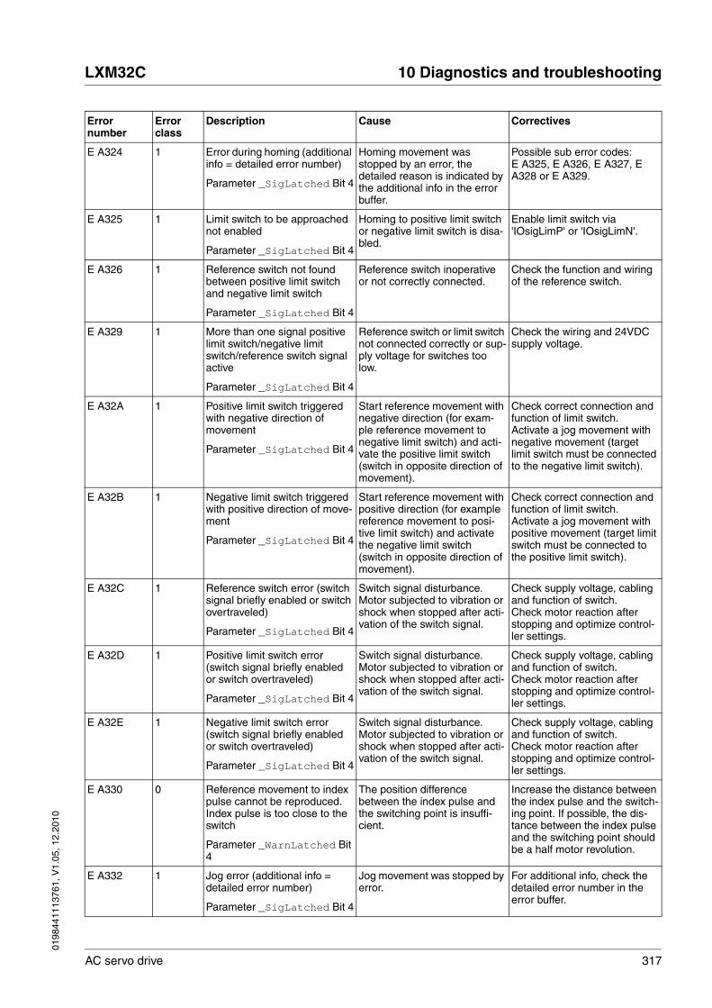
0198
4411
1376
1, V
1.05
, 12.
2010
LXM32C 10 Diagnostics and troubleshooting
AC servo drive 317
E A324 1 Error during homing (additional info = detailed error number)
Parameter _SigLatched Bit 4
Homing movement was stopped by an error, the detailed reason is indicated by the additional info in the error buffer.
Possible sub error codes:E A325, E A326, E A327, E A328 or E A329.
E A325 1 Limit switch to be approached not enabled
Parameter _SigLatched Bit 4
Homing to positive limit switch or negative limit switch is disa-bled.
Enable limit switch via 'IOsigLimP' or 'IOsigLimN'.
E A326 1 Reference switch not found between positive limit switch and negative limit switch
Parameter _SigLatched Bit 4
Reference switch inoperative or not correctly connected.
Check the function and wiring of the reference switch.
E A329 1 More than one signal positive limit switch/negative limit switch/reference switch signal active
Parameter _SigLatched Bit 4
Reference switch or limit switch not connected correctly or sup-ply voltage for switches too low.
Check the wiring and 24VDC supply voltage.
E A32A 1 Positive limit switch triggered with negative direction of movement
Parameter _SigLatched Bit 4
Start reference movement with negative direction (for exam-ple reference movement to negative limit switch) and acti-vate the positive limit switch (switch in opposite direction of movement).
Check correct connection and function of limit switch.Activate a jog movement with negative movement (target limit switch must be connected to the negative limit switch).
E A32B 1 Negative limit switch triggered with positive direction of move-ment
Parameter _SigLatched Bit 4
Start reference movement with positive direction (for example reference movement to posi-tive limit switch) and activate the negative limit switch (switch in opposite direction of movement).
Check correct connection and function of limit switch.Activate a jog movement with positive movement (target limit switch must be connected to the positive limit switch).
E A32C 1 Reference switch error (switch signal briefly enabled or switch overtraveled)
Parameter _SigLatched Bit 4
Switch signal disturbance.Motor subjected to vibration or shock when stopped after acti-vation of the switch signal.
Check supply voltage, cabling and function of switch.Check motor reaction after stopping and optimize control-ler settings.
E A32D 1 Positive limit switch error (switch signal briefly enabled or switch overtraveled)
Parameter _SigLatched Bit 4
Switch signal disturbance.Motor subjected to vibration or shock when stopped after acti-vation of the switch signal.
Check supply voltage, cabling and function of switch.Check motor reaction after stopping and optimize control-ler settings.
E A32E 1 Negative limit switch error (switch signal briefly enabled or switch overtraveled)
Parameter _SigLatched Bit 4
Switch signal disturbance.Motor subjected to vibration or shock when stopped after acti-vation of the switch signal.
Check supply voltage, cabling and function of switch.Check motor reaction after stopping and optimize control-ler settings.
E A330 0 Reference movement to index pulse cannot be reproduced. Index pulse is too close to the switch
Parameter _WarnLatched Bit 4
The position difference between the index pulse and the switching point is insuffi-cient.
Increase the distance between the index pulse and the switch-ing point. If possible, the dis-tance between the index pulse and the switching point should be a half motor revolution.
E A332 1 Jog error (additional info = detailed error number)
Parameter _SigLatched Bit 4
Jog movement was stopped by error.
For additional info, check the detailed error number in the error buffer.
Error number
Error class
Description Cause Correctives

318 AC servo drive
10 Diagnostics and troubleshooting LXM32C
0198
4411
1376
1, V
1.05
, 12.
2010
E A334 2 Timeout Standstill Window monitoring
Position deviation after move-ment greater than standstill window. This may have been caused by an external load.
Check load.Check settings for standstill window (parameter MON_p_win, MON_p_winTime and MON_p_winTout).Optimize controller settings.
E A337 0 Operating mode cannot be continued
Parameter _WarnLatched Bit 4
Continuation of interrupted movement in operating mode Profile Position is not possible because another operating mode had been active in the meantime.In the operating mode Motion Sequence, continuation is not possible if a motion blend was interrupted.
Restart the operating mode.
E A33A 0 Reference point is not defined (ref_ok=0)
Parameter _WarnLatched Bit 4
No reference point defined by means of operating mode Homing.Reference position lost because the movement range has been left.Motor does not have an abso-lute encoder.
Use operating mode Homing to define a reference point.Use a motor with an absolute encoder.
E A33D 0 Motion blend is already active
Parameter _WarnLatched Bit 4
Change of motion blend during the current motion blend (end position of motion blend not yet reached)
Wait for the motion blend to complete before setting the next position.
E A33E 0 No movement activated
Parameter _WarnLatched Bit 4
Activation of a motion blend without movement.
Start a movement before the motion blend is activated.
E A33F 0 Position of motion blend move-ment not in the range of the active movement
Parameter _WarnLatched Bit 4
The position of the motion blend is outside of the current movement range.
Check the position of the motion blend and the current movement range.
E A341 0 Position of motion blend has already been passed
Parameter _WarnLatched Bit 4
The current movement has passed beyond the position of the motion blend.
E A342 1 Target velocity was not reached at motion blend posi-tion.
Parameter _SigLatched Bit 4
The position of the motion blend was overtraveled, the target velocity was not reached.
Reduce the ramp velocity so that the target velocity is reached at the position of the motion blend.
E A347 0 Threshold for position devia-tion warning reached
Parameter _WarnLatched Bit 8
External load or acceleration are too high.
Reduce external load or accel-eration.Threshold can be adjusted via the parameter MON_p_dif_warn.
E A348 1 No analog reference value source selected
Parameter _SigLatched Bit 4
No analog reference value selected
Select an analog reference value source.
E A34D - The function is not possible when Modulo is active.
The function cannot be exe-cuted when Modulo is active.
Deactivate Modulo to use the function.
Error number
Error class
Description Cause Correctives

0198
4411
1376
1, V
1.05
, 12.
2010
LXM32C 10 Diagnostics and troubleshooting
AC servo drive 319
E A34E - Target value for absolute movement not possible with defined modulo range and modulo handling.
If parameter 'MOD_Absolute' is set to:Shortest Distance: Target value is not in defined modulo range.Positive Direction: Target value is less than parameter 'MOD_Min'.Negative Direction: Target value is greater than parameter 'MOD_Max'.
Set a correct target value for absolute movement.
E A34F - Target position outside of mod-ulo range. Corresponding movement within range per-formed instead.
The current setting of parame-ter 'MOD_AbsMultiRng' only allows for a movement within the modulo range.
Change the parameter 'MOD_AbsMultiRng' to allow for movements beyond the modulo range.
E A350 1 Change for jerk filter input posi-tion too great
Parameter _SigLatched Bit 4
Operating mode Electronic Gear with processing method 'Position synchronization with compensation movement' has been activated which resulted in a position change greater than 0.25 revolutions.
Deactivate jerk filter process-ing for Electronic Gear or use processing method 'Position synchronization without com-pensation movement'.
E A351 1 Function cannot be executed with the current position scal-ing factor
Parameter _SigLatched Bit 4
The positions scaling factor is set to a value less than 1rev/131072usr_p, which is less than the internal resolution.In the operating mode Cyclic Synchronous Position, the res-olution is not set to 1rev/131072usr_p.
Use a different position scaling factor or deactivate the selected function.
E A355 1 Error during relative movement after capture (additional info = detailed error number)
Parameter _SigLatched Bit 4
Movement was stopped by error.
Check the error memory or the parameter _LastError_Qual for additional information.
E A356 0 Function Relative Movement After Capture not assigned to a digital input.
Assign the function Relative Movement After Capture to a digital input.
E A357 - Braking procedure still active Command is not allowed when a braking procedure is active.
Wait until motor has come to a complete standstill.
E A358 1 Target position overtraveled with function Relative Move-ment After Capture
Parameter _SigLatched Bit 4
Stopping distance too small or velocity too high at the point in time of the capture event.
Reduce the velocity.
E A359 0 Request cannot be processed since the relative movement after capture is still active
E B100 0 RS485/Modbus: Unknown service
Parameter _WarnLatched Bit 5
Unsupported Modbus service was received.
Check application on the Mod-bus master.
E B200 0 RS485/Modbus: Protocol error
Parameter _WarnLatched Bit 5
Logical protocol error: Wrong length or unsupported sub-function.
Check application on the Mod-bus master.
Error number
Error class
Description Cause Correctives

320 AC servo drive
10 Diagnostics and troubleshooting LXM32C
0198
4411
1376
1, V
1.05
, 12.
2010
E B201 2 RS485/Modbus: Node Guard-ing error
Parameter _SigLatched Bit 5
Connection monitoring (param-eter MBnode_guard) is <>0ms and a nodeguard event was detected.
Check application on the Mod-bus master or change value (set to 0ms or increase the parameter MBnode_guard monitoring time).
E B202 0 RS485/Modbus: Node Guard-ing warning
Parameter _WarnLatched Bit 5
Connection monitoring (param-eter MBnode_guard) is <>0ms and a Node Guarding event was detected.
Check application on the Mod-bus master or change value (set to 0ms or increase the parameter MBnode_guard monitoring time).
Error number
Error class
Description Cause Correctives

0198
4411
1376
1, V
1.05
, 12.
2010
LXM32C 11 Parameters
AC servo drive 321
1111 Parameters
This chapter provides an overview of the parameters which can be used for operating the product.
In addition, special parameters for communication via the fieldbus are described in the corresponding fieldbus manual.
11.1 Representation of the parameters
The way parameters are shown provides information required for unique identification, the default values and the properties of a parameter.
Structure of the parameter representation:
Parameter name The parameter name uniquely identifies a parameter.
HMI menu HMI menu shows the sequence of menus and commands to access the parameter via the HMI.
@ WARNINGUNINTENDED BEHAVIOR CAUSED BY PARAMETERS
The behavior of the drive system is governed by numerous parame-ters. Unsuitable parameter values can trigger unintended movements or signals or deactivate monitoring functions.
• Never change a parameter unless you understand its meaning.
• Only start the system if there are no persons or obstructions in the hazardous area.
• When commissioning, carefully run tests for all operating states and potential fault situations.
Failure to follow these instructions can result in death, serious injury or equipment damage.
Parameter nameHMI menuHMI name
Description UnitMinimum valueFactory settingMaximum value
Data typeR/WPersistentExpert
Parameter address via fieldbus
Example_Name
ConF → inF-
Prn
Short description (cross reference)
Selection values1 / Selection value 1 / ABC1: Explanation 12 / Selection value 2 / ABC2: Explanation 2
Description and details
Apk0.003.00300.00
UINT32R/Wper.-
Fieldbus 1234:5h
322 AC servo drive
11 Parameters LXM32C
0198
4411
1376
1, V
1.05
, 12.
2010
Description Short description (cross reference)The short description contains information on the parameter and a cross reference to the page that describes the use of the parameter.
Selection valuesIn the case of parameters which offer a selection of settings, the value to be entered via the fieldbus and the designation of the value for input via the commissioning software and the HMI are specified.1 = Value via fieldbusSelection value1 = Selection value via commissioning softwareABC1 = Selection value via HMI
Further description and detailsProvides further information on the parameter.
Unit The unit of the value.
Minimum value The minimum value which can be entered.
Factory setting Factory settings when the product is shipped
Maximum value The maximum value which can be entered.
Data type If the minimum and the maximum values are not explicitly indicated, the valid range of values is determined by the data type.
R/W Indicates read and/or write values
"R/" values can only be read"R/W" values can be read and written.
Persistent "per." indicates whether the value of the parameter is persistent, i.e. whether it remains in the memory after the device is switched off .
When a value is entered via the HMI, the device stores the value of the parameter automatically each time it is changed.
When changing a value via commissioning software or fieldbus, the user must explicitly store the changed value in the persistent memory.
Data type Byte Minumum value Maximum value
INT8 1 Byte / 8 Bit -128 127
UINT8 1 Byte / 8 Bit 0 255
INT16 2 Byte / 16 Bit -32768 32767
UINT16 2 Byte / 16 Bit 0 65535
INT32 4 Byte / 32 Bit -2147483648 2147483647
UINT32 4 Byte / 32 Bit 0 4294967295

0198
4411
1376
1, V
1.05
, 12.
2010
LXM32C 11 Parameters
AC servo drive 323
11.1.1 Decimal numbers for fieldbus
Entering values Please note that parameter values are entered via the fieldbus without a decimal point. All decimal places must be entered.
Input examples:
Value Commissioning software Fieldbus
20 20 20
5.0 5.0 50
23.57 23.57 2357
1.000 1.000 1000

324 AC servo drive
11 Parameters LXM32C
0198
4411
1376
1, V
1.05
, 12.
2010
11.2 List of parameters
Parameter nameHMI menuHMI name
Description UnitMinimum valueFactory settingMaximum value
Data typeR/WPersistentExpert
Parameter address via fieldbus
_AccessInfo Current access channel
Low byte:Value 0: Used by channel in high byteValue 1: Exclusively used by channel in high byte
High byte: Current assignment of access channelValue 0: ReservedValue 1: I/OValue 2: HMIValue 3: Modbus RS485Value 4: Fieldbus main channelValues 5 ... 12: Modbus TCP, CANopen sec-ond SDO or Profibus master class 2Values 13 ... 28: Ethenet/IP explicit channels
----
UINT16R/---
Modbus 280
_AI1_act
Mon
AnA1
Analog 1: Value of input voltage (154) mV-10000-10000
INT16R/---
Modbus 2306
_AI2_act
Mon
AnA2
Analog 2: Value of input voltage (154) mV-10000-10000
INT16R/---
Modbus 2314
_AT_J Moment of inertia of the complete system (174)
Is automatically calculated during Autotun-ing.
In increments of 0.1 kg cm2.
kg cm2
0.10.16553.5
UINT16R/-per.-
Modbus 12056
_AT_M_friction Friction torque of the system (173)
Is determined during Autotuning.
In increments of 0.01 Arms.
Arms---
UINT16R/---
Modbus 12046
_AT_M_load Constant load torque (173)
Is determined during Autotuning.
In increments of 0.01 Arms.
Arms---
INT16R/---
Modbus 12048
_AT_progress Progress of Autotuning (173) %00100
UINT16R/---
Modbus 12054
_AT_state Autotuning status (173)
Bit assignments:Bits 0 ... 10: Last processing stepBit 13: auto_tune_processBit 14: auto_tune_endBit 15: auto_tune_err
----
UINT16R/---
Modbus 12036

0198
4411
1376
1, V
1.05
, 12.
2010
LXM32C 11 Parameters
AC servo drive 325
_Cond_State4 Conditions for transition to operating state Ready To Switch On
Signal state:0: Condition not met1: Condition met
Bit 0: DC bus or mains voltageBit 1: Inputs for safety functionBit 2: No configuration download ongoingBit 3: Velocity greater than limit valueBit 4: Absolut position has been setBit 5: Holding brake not manually released
----
UINT16R/---
Modbus 7244
_CTRL_ActParSet Active controller parameter set (150)
Value 1: Controller parameter set 1 is activeValue 2: Controller parameter set 2 is active
A controller parameter set is active after the time for the parameter switching (CTRL_ParChgTime) has elapsed.
----
UINT16R/---
Modbus 4398
_CTRL_KPid Current controller d component P gain
This value is calculated on the basis of the motor parameters.
In increments of 0.1 V/A.
V/A0.5-1270.0
UINT16R/-per.-
Modbus 4354
_CTRL_KPiq Current controller q component P gain
This value is calculated on the basis of the motor parameters.
In increments of 0.1 V/A.
V/A0.5-1270.0
UINT16R/-per.-
Modbus 4358
_CTRL_TNid Current controller d component integral action time
This value is calculated on the basis of the motor parameters.
In increments of 0.01 ms.
ms0.13-327.67
UINT16R/-per.-
Modbus 4356
_CTRL_TNiq Current controller q component integral action time
This value is calculated on the basis of the motor parameters.
In increments of 0.01 ms.
ms0.13-327.67
UINT16R/-per.-
Modbus 4360
_DCOMstatus DriveCom status word
Bits 0 ... 3: Status bitsBit 4: Voltage enabledBits 5 ... 6: Status bitsBit 7: WarningBit 8: HALT request activeBit 9: RemoteBit 10: Target reachedBit 11: Internal limitBit 12: Operating mode-specificBit 13: x_errBit 14: x_endBit 15: ref_ok
The meaning of bit 11 can be set via the parameter DS402intLim.
----
UINT16R/---
Modbus 6916
Parameter nameHMI menuHMI name
Description UnitMinimum valueFactory settingMaximum value
Data typeR/WPersistentExpert
Parameter address via fieldbus

326 AC servo drive
11 Parameters LXM32C
0198
4411
1376
1, V
1.05
, 12.
2010
_DEV_T_current
Mon
tdEV
Current device temperature °C---
INT16R/---
Modbus 7204
_DPL_BitShiftRefA16
Bit shift for RefA16 for Drive Profile Lexium
Velocity scaling may lead to values that can-not be represented as 16 bit values. If RefA16 is used, this parameter indicates the number of bits by which the value is shifted so that transmission is possible. The master must consider this value prior to transmis-sion and shift the bits to the right accordingly. The number of bits is recalculated each time the power stage is enabled.
Changed settings become active immedi-ately.
-0012
UINT16R/---
Modbus 6922
_DPL_driveInput Drive Profile Lexium driveInput ----
UINT16R/---
Modbus 6992
_DPL_driveStat Drive Profile Lexium driveStat ----
UINT16R/---
Modbus 6986
_DPL_mfStat Drive Profile Lexium mfStat ----
UINT16R/---
Modbus 6988
_DPL_motionStat Drive Profile Lexium motionStat ----
UINT16R/---
Modbus 6990
_I_act
Mon
iAct
Total motor current
In increments of 0.01 Arms.
Arms---
INT16R/---
Modbus 7686
_Id_act_rms Actual motor current (d component, field weakening)
In increments of 0.01 Arms.
Arms---
INT16R/---
Modbus 7684
_Id_ref_rms Reference motor current (d component, field weakening)
In increments of 0.01 Arms.
Arms---
INT16R/---
Modbus 7714
Parameter nameHMI menuHMI name
Description UnitMinimum valueFactory settingMaximum value
Data typeR/WPersistentExpert
Parameter address via fieldbus
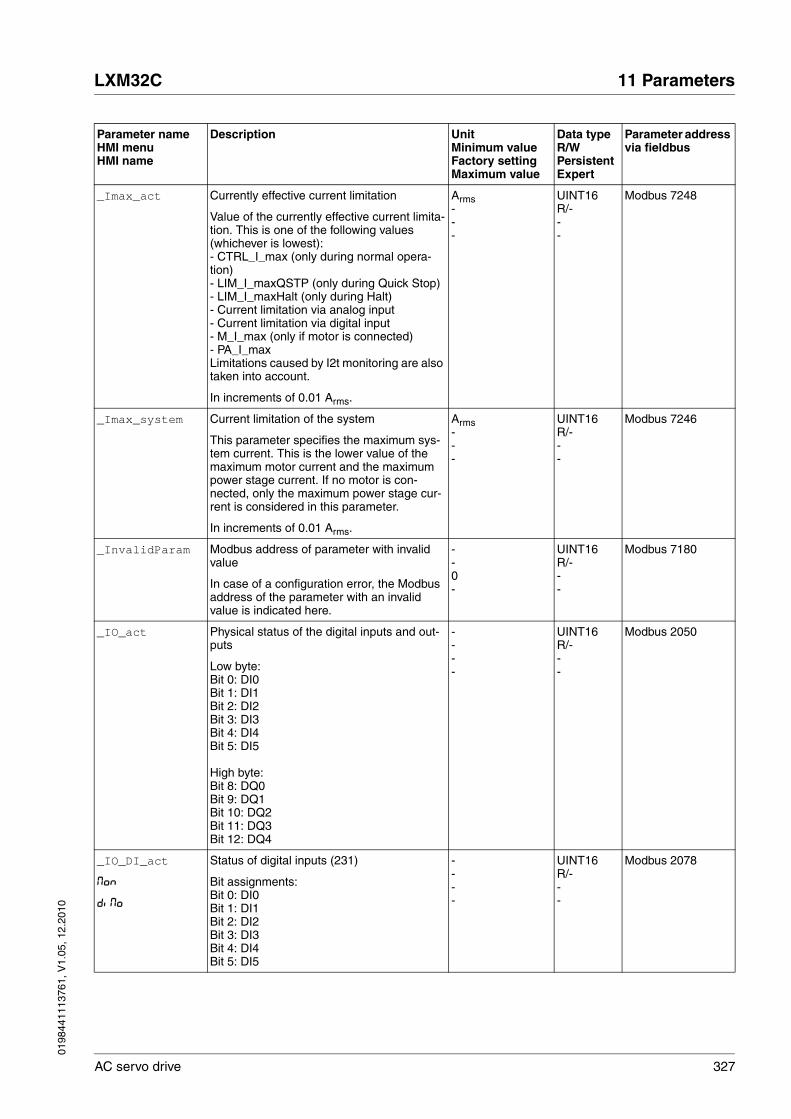
0198
4411
1376
1, V
1.05
, 12.
2010
LXM32C 11 Parameters
AC servo drive 327
_Imax_act Currently effective current limitation
Value of the currently effective current limita-tion. This is one of the following values (whichever is lowest):- CTRL_I_max (only during normal opera-tion)- LIM_I_maxQSTP (only during Quick Stop)- LIM_I_maxHalt (only during Halt)- Current limitation via analog input- Current limitation via digital input - M_I_max (only if motor is connected)- PA_I_maxLimitations caused by I2t monitoring are also taken into account.
In increments of 0.01 Arms.
Arms---
UINT16R/---
Modbus 7248
_Imax_system Current limitation of the system
This parameter specifies the maximum sys-tem current. This is the lower value of the maximum motor current and the maximum power stage current. If no motor is con-nected, only the maximum power stage cur-rent is considered in this parameter.
In increments of 0.01 Arms.
Arms---
UINT16R/---
Modbus 7246
_InvalidParam Modbus address of parameter with invalid value
In case of a configuration error, the Modbus address of the parameter with an invalid value is indicated here.
--0-
UINT16R/---
Modbus 7180
_IO_act Physical status of the digital inputs and out-puts
Low byte:Bit 0: DI0Bit 1: DI1Bit 2: DI2Bit 3: DI3Bit 4: DI4Bit 5: DI5
High byte:Bit 8: DQ0Bit 9: DQ1Bit 10: DQ2Bit 11: DQ3Bit 12: DQ4
----
UINT16R/---
Modbus 2050
_IO_DI_act
Mon
diMo
Status of digital inputs (231)
Bit assignments:Bit 0: DI0Bit 1: DI1Bit 2: DI2Bit 3: DI3Bit 4: DI4Bit 5: DI5
----
UINT16R/---
Modbus 2078
Parameter nameHMI menuHMI name
Description UnitMinimum valueFactory settingMaximum value
Data typeR/WPersistentExpert
Parameter address via fieldbus

328 AC servo drive
11 Parameters LXM32C
0198
4411
1376
1, V
1.05
, 12.
2010
_IO_DQ_act
Mon
doMo
Status of digital outputs (231)
Bit assignments:Bit 0: DQ0Bit 1: DQ1Bit 2: DQ2Bit 3: DQ3Bit 4: DQ4
----
UINT16R/---
Modbus 2080
_IO_STO_act
Mon
Sto
Status of the inputs for the safety function STO
Coding of the individual signals:Bit 0: STO_ABit 1: STO_B
----
UINT16R/---
Modbus 2124
_Iq_act_rms
Mon
qAct
Actual motor current (q component, generat-ing torque)
In increments of 0.01 Arms.
Arms---
INT16R/---
Modbus 7682
_Iq_ref_rms
Mon
qrEF
Reference motor current (q component, gen-erating torque)
In increments of 0.01 Arms.
Arms---
INT16R/---
Modbus 7712
_LastError
Mon
LFLt
Error causing a stop (error classes 1 to 4)
Number of the current error. Any conseq-utive errors do not overwrite this error number.
Example: If a limit switch error reaction caused an overvoltage error, this parameter would contain the number of the limit switch error.
Exception: Errors of error class 4 overwrite existing entries.
--0-
UINT16R/---
Modbus 7178
_LastWarning
Mon
LWrn
Number of last warning (error class 0)
Number of the most recent warning.If the warning becomes inactive again, the number is memorized until the next fault reset.Value 0: No warning occurred
----
UINT16R/---
Modbus 7186
_M_BRK_T_apply Holding brake application time ms---
UINT16R/---
Modbus 3394
_M_BRK_T_release
Holding brake release time ms---
UINT16R/---
Modbus 3396
Parameter nameHMI menuHMI name
Description UnitMinimum valueFactory settingMaximum value
Data typeR/WPersistentExpert
Parameter address via fieldbus
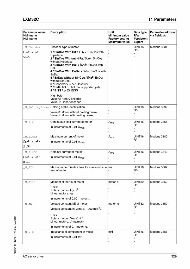
0198
4411
1376
1, V
1.05
, 12.
2010
LXM32C 11 Parameters
AC servo drive 329
_M_Encoder
ConF → inF-
SEnS
Encoder type of motor
1 / SinCos With HiFa / SWhi: SinCos with Hiperface2 / SinCos Without HiFa / SWoh: SinCos without Hiperface3 / SinCos With Hall / SWhA: SinCos with Hall4 / SinCos With EnDat / SWEn: SinCos with EnDat5 / EnDat Without SinCos / EndA: EnDat without SinCos6 / Resolver / rESo: Resolver7 / Hall / hALL: Hall (not supported yet)8 / BISS / biSS: BISS
High byte:Value 0: Rotary encoderValue 1: Linear encoder
----
UINT16R/---
Modbus 3334
_M_HoldingBrake Holding brake identification
Value 0: Motor without holding brakeValue 1: Motor with holding brake
----
UINT16R/---
Modbus 3392
_M_I_0 Continuous stall current of motor
In increments of 0.01 Arms.
Arms---
UINT16R/---
Modbus 3366
_M_I_max
ConF → inF-
MiMA
Maximum current of motor
In increments of 0.01 Arms.
Arms---
UINT16R/---
Modbus 3340
_M_I_nom
ConF → inF-
Mino
Nominal current of motor
In increments of 0.01 Arms.
Arms---
UINT16R/---
Modbus 3342
_M_I2t Maximum permissible time for maximum cur-rent of motor
ms---
UINT16R/---
Modbus 3362
_M_Jrot Moment of inertia of motor
Units:Rotary motors: kgcm2
Linear motors: kg
In increments of 0.001 motor_f.
motor_f---
UINT32R/---
Modbus 3352
_M_kE Voltage constant kE of motor
Voltage constant in Vrms at 1000 min-1.
Units:Rotary motors: Vrms/min-1
Linear motors: Vrms/(m/s)
In increments of 0.1 motor_u.
motor_u---
UINT32R/---
Modbus 3350
_M_L_d Inductance d component of motor
In increments of 0.01 mH.
mH---
UINT16R/---
Modbus 3358
Parameter nameHMI menuHMI name
Description UnitMinimum valueFactory settingMaximum value
Data typeR/WPersistentExpert
Parameter address via fieldbus

330 AC servo drive
11 Parameters LXM32C
0198
4411
1376
1, V
1.05
, 12.
2010
_M_L_q Inductance q component of motor
In increments of 0.01 mH.
mH---
UINT16R/---
Modbus 3356
_M_load
Mon
LdFM
Current load of motor (287) %---
INT16R/---
Modbus 7220
_M_M_0 Continuous stall torque of motor
A value of 100 % in operating mode Profile Torque corresponds to this parameter.
Units:Rotary motors: NcmLinear motors: N
motor_m---
UINT16R/---
Modbus 3372
_M_M_max Maximum torque of motor
In increments of 0.1 Nm.
Nm---
UINT16R/---
Modbus 3346
_M_M_nom Nominal torque/force of motor
Units:Rotary motors: NcmLinear motors: N
motor_m---
UINT16R/---
Modbus 3344
_M_maxoverload Maximum value of overload of motor (288)
Maximum overload of motor during the last 10 seconds.
%---
INT16R/---
Modbus 7222
_M_n_max
ConF → inF-
MnMA
Maximum permissible speed of rotation/velocity of motor
Units:Rotary motors: min-1
Linear motors: mm/s
motor_v---
UINT16R/---
Modbus 3336
_M_n_nom Nominal speed of rotation/velocity of motor
Units:Rotary motors: min-1
Linear motors: mm/s
motor_v---
UINT16R/---
Modbus 3338
_M_overload Current overload of motor (I2t) (287) %---
INT16R/---
Modbus 7218
_M_Polepair Number of pole pairs of motor ----
UINT16R/---
Modbus 3368
_M_PolePairPitch
Pole pair pitch of motor
In increments of 0.01 mm.
mm---
UINT16R/---
Modbus 3398
_M_R_UV Winding resistance of motor
In increments of 0.01 Ω.
Ω---
UINT16R/---
Modbus 3354
Parameter nameHMI menuHMI name
Description UnitMinimum valueFactory settingMaximum value
Data typeR/WPersistentExpert
Parameter address via fieldbus

0198
4411
1376
1, V
1.05
, 12.
2010
LXM32C 11 Parameters
AC servo drive 331
_M_T_current Current motor temperature (286)
No meaningful indication possible for switch-ing temperature sensors (see parameter M_TempType for temperature sensor type)
°C---
INT16R/---
Modbus 7202
_M_T_max Maximum temperature of motor (286) °C---
INT16R/---
Modbus 3360
_M_Type
ConF → inF-
MtyP
Motor type
Value 0: No motor selectedValue >0: Connected motor type
----
UINT32R/---
Modbus 3332
_M_U_max Maximum voltage of motor
In increments of 0.1 V.
V---
UINT16R/---
Modbus 3378
_M_U_nom Nominal voltage of motor
In increments of 0.1 V.
V---
UINT16R/---
Modbus 3348
_n_act_ENC1 Actual speed of rotation of encoder 1 min-1
---
INT16R/---
Modbus 7760
_n_act
Mon
nAct
Actual speed of rotation min-1
---
INT16R/---
Modbus 7696
_n_ref
Mon
nrEF
Reference speed of rotation min-1
---
INT16R/---
Modbus 7694
_OpHours
Mon
oPh
Operating hours counter s---
UINT32R/---
Modbus 7188
_p_absENC Absolute position with reference to the encoder range (164)
This value corresponds to the modulo posi-tion of the absolute encoder range.The value is no longer valid if the gear ratio of machine encoder and motor encoder is changed. A restart is required in such a case.
usr_p---
UINT32R/---
Modbus 7710
_p_absmodulo Absolute position with reference to internal resolution in internal units
This value is based on encoder raw position with reference to internal resolution (131072 Inc).
Inc---
UINT32R/---
Modbus 7708
_p_act_ENC1_int Actual position of encoder 1 in internal units Inc---
INT32R/---
Modbus 7756
Parameter nameHMI menuHMI name
Description UnitMinimum valueFactory settingMaximum value
Data typeR/WPersistentExpert
Parameter address via fieldbus
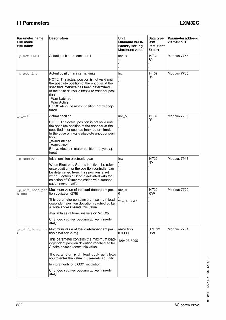
332 AC servo drive
11 Parameters LXM32C
0198
4411
1376
1, V
1.05
, 12.
2010
_p_act_ENC1 Actual position of encoder 1 usr_p---
INT32R/---
Modbus 7758
_p_act_int Actual position in internal units
NOTE: The actual position is not valid until the absolute position of the encoder at the specified interface has been determined.In the case of invalid absolute encoder posi-tion:_WarnLatched_WarnActiveBit 13: Absolute motor position not yet cap-tured
Inc---
INT32R/---
Modbus 7700
_p_act Actual position
NOTE: The actual position is not valid until the absolute position of the encoder at the specified interface has been determined.In the case of invalid absolute encoder posi-tion:_WarnLatched_WarnActiveBit 13: Absolute motor position not yet cap-tured
usr_p---
INT32R/---
Modbus 7706
_p_addGEAR Initial position electronic gear
When Electronic Gear is inactive, the refer-ence position for the position controller can be determined here. This position is set when Electronic Gear is activated with the selection of 'Synchronization with compen-sation movement'.
Inc---
INT32R/---
Modbus 7942
_p_dif_load_peak_usr
Maximum value of the load-dependent posi-tion deviation (275)
This parameter contains the maximum load-dependent position deviation reached so far. A write access resets this value.
Available as of firmware version V01.05
Changed settings become active immedi-ately.
usr_p0-2147483647
INT32R/W--
Modbus 7722
_p_dif_load_peak
Maximum value of the load-dependent posi-tion deviation (275)
This parameter contains the maximum load-dependent position deviation reached so far. A write access resets this value.
The parameter _p_dif_load_peak_usr allows you to enter the value in user-defined units..
In increments of 0.0001 revolution.
Changed settings become active immedi-ately.
revolution0.0000-429496.7295
UINT32R/W--
Modbus 7734
Parameter nameHMI menuHMI name
Description UnitMinimum valueFactory settingMaximum value
Data typeR/WPersistentExpert
Parameter address via fieldbus

0198
4411
1376
1, V
1.05
, 12.
2010
LXM32C 11 Parameters
AC servo drive 333
_p_dif_load_usr Current load-dependent position deviation between reference and actual position (274)
The load-dependent position deviation is the difference between the reference position and the actual position caused by the load. This value is used for following error monitor-ing.
Available as of firmware version V01.05
usr_p-2147483648-2147483647
INT32R/---
Modbus 7724
_p_dif_load Current load-dependent position deviation between reference and actual position (274)
The load-dependent position deviation is the difference between the reference position and the actual position caused by the load. This value is used for following error monitor-ing.
The parameter _p_dif_load_usr allows you to enter the value in user-defined units.
In increments of 0.0001 revolution.
revolution-214748.3648-214748.3647
INT32R/---
Modbus 7736
_p_dif_usr Current position deviation including dynamic position deviation
Position deviation is the difference between reference position and actual position. The current position deviation consists of the load-dependent position deviation and the dynamic position deviation.
Available as of firmware version V01.05
usr_p-2147483648-2147483647
INT32R/---
Modbus 7720
_p_dif Current position deviation including dynamic position deviation
Position deviation is the difference between reference position and actual position. The current position deviation consists of the load-dependent position deviation and the dynamic position deviation.
The parameter _p_dif_usr allows you to enter the value in user-defined units.
In increments of 0.0001 revolution.
revolution-214748.3648-214748.3647
INT32R/---
Modbus 7716
_p_PTI_act Actual position at PTI interface
Counted position increments at position interface PTI.
Inc-2147483648-2147483647
INT32R/---
Modbus 2058
_p_ref_int Reference position in internal units
Value corresponds to the reference position of the position controller.
Inc---
INT32R/---
Modbus 7698
_p_ref Reference position
Value corresponds to the reference position of the position controller.
usr_p---
INT32R/---
Modbus 7704
Parameter nameHMI menuHMI name
Description UnitMinimum valueFactory settingMaximum value
Data typeR/WPersistentExpert
Parameter address via fieldbus
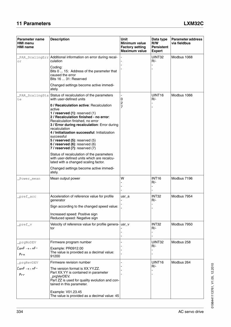
334 AC servo drive
11 Parameters LXM32C
0198
4411
1376
1, V
1.05
, 12.
2010
_PAR_ScalingError
Additional information on error during recal-culation
Coding:Bits 0 ... 15: Address of the parameter that caused the errorBits 16 ... 31: Reserved
Changed settings become active immedi-ately.
----
UINT32R/---
Modbus 1068
_PAR_ScalingState
Status of recalculation of the parameters with user-defined units
0 / Recalculation active: Recalculation active1 / reserved (1): reserved (1)2 / Recalculation finished - no error: Recalculation finished, no error3 / Error during recalculation: Error during recalculation4 / Initialization successful: Initialization successful5 / reserved (5): reserved (5)6 / reserved (6): reserved (6)7 / reserved (7): reserved (7)
Status of recalculation of the parameters with user-defined units which are recalcu-lated with a changed scaling factor.
Changed settings become active immedi-ately.
-027
UINT16R/---
Modbus 1066
_Power_mean Mean output power W---
INT16R/---
Modbus 7196
_pref_acc Acceleration of reference value for profile generator
Sign according to the changed speed value:
Increased speed: Positive signReduced speed: Negative sign
usr_a---
INT32R/---
Modbus 7954
_pref_v Velocity of reference value for profile genera-tor
usr_v---
INT32R/---
Modbus 7950
_prgNoDEV
ConF → inF-
Prn
Firmware program number
Example: PR0912.00The value is provided as a decimal value: 91200
----
UINT32R/---
Modbus 258
_prgRevDEV
ConF → inF-
Prr
Firmware revision number
The version format is XX.YY.ZZ.Part XX.YY is contained in parameter _prgVerDEV.Part ZZ is used for quality evolution and con-tained in this parameter.
Example: V01.23.45The value is provided as a decimal value: 45
----
UINT16R/---
Modbus 264
Parameter nameHMI menuHMI name
Description UnitMinimum valueFactory settingMaximum value
Data typeR/WPersistentExpert
Parameter address via fieldbus
0198
4411
1376
1, V
1.05
, 12.
2010
LXM32C 11 Parameters
AC servo drive 335
_prgVerDEV
ConF → inF-
PrV
Firmware version number
The version format is XX.YY.ZZ.Part XX.YY is contained in this parameter.Part ZZ is contained in parameter _prgRevDEV.
Example: V01.23.45The value is provided as a decimal value: 123
----
UINT16R/---
Modbus 260
_PS_I_max
ConF → inF-
PiMA
Maximum current of power stage
In increments of 0.01 Arms.
Arms---
UINT16R/-per.-
Modbus 4100
_PS_I_nom
ConF → inF-
Pino
Nominal current of power stage
In increments of 0.01 Arms.
Arms---
UINT16R/-per.-
Modbus 4098
_PS_load
Mon
LdFP
Current load of power stage (287) %---
INT16R/---
Modbus 7214
_PS_maxoverload Maximum value of overload of power stage (287)
Maximum overload of power stage during the last 10 seconds.
%---
INT16R/---
Modbus 7216
_PS_overload_I2t
Current overload of power stage (I2t) %---
INT16R/---
Modbus 7212
_PS_T_current
Mon
tPS
Current power stage temperature (286) °C---
INT16R/---
Modbus 7200
_PS_T_max Maximum power stage temperature (286) °C---
INT16R/-per.-
Modbus 4110
_PS_T_warn Temperature warning threshold of power stage (286)
°C---
INT16R/-per.-
Modbus 4108
_PS_U_maxDC Maximum permissible DC bus voltage
In increments of 0.1 V.
V---
UINT16R/-per.-
Modbus 4102
_PS_U_minDC Minimum permissible DC bus voltage
In increments of 0.1 V.
V---
UINT16R/-per.-
Modbus 4104
_PS_U_minStopDC DC bus voltage low threshold for Quick Stop
If this threshold is reached, the drive per-forms a Quick Stop.
In increments of 0.1 V.
V---
UINT16R/-per.-
Modbus 4116
Parameter nameHMI menuHMI name
Description UnitMinimum valueFactory settingMaximum value
Data typeR/WPersistentExpert
Parameter address via fieldbus

336 AC servo drive
11 Parameters LXM32C
0198
4411
1376
1, V
1.05
, 12.
2010
_RAMP_p_act Actual position of profile generator usr_p---
INT32R/---
Modbus 7940
_RAMP_p_target Target position of profile generator
Absolute position value of the profile genera-tor, calculated on the basis of the relative and absolute position values received.
usr_p---
INT32R/---
Modbus 7938
_RAMP_v_act Actual velocity of profile generator usr_v---
INT32R/---
Modbus 7948
_RAMP_v_target Target velocity of profile generator usr_v---
INT32R/---
Modbus 7946
_RES_load
Mon
LdFb
Current load of braking resistor (287)
Monitoring of internal and external braking resistor depending on parameter RESint_ext.
%---
INT16R/---
Modbus 7208
_RES_maxoverload
Maximum value of overload of braking resistor (288)
Maximum overload of braking resistor during the last 10 seconds.
%---
INT16R/---
Modbus 7210
_RES_overload Current overload of braking resistor (I2t) (288)
Monitoring of internal and external braking resistor depending on parameter RESint_ext.
%---
INT16R/---
Modbus 7206
_RESint_P Nominal power of internal braking resistor W---
UINT16R/-per.-
Modbus 4114
_RESint_R Resistance value of internal braking resistor
In increments of 0.01 Ω.
Ω---
UINT16R/-per.-
Modbus 4112
_ScalePOSmax Maximum user-defined value for positions
This value depends on ScalePOSdenom and ScalePOSnum.
usr_p---
INT32R/---
Modbus 7956
_ScaleRAMPmax Maximum user-defined value for accelera-tions and decelerations
This value depends on ScaleRAMPdenom and ScaleRAMPnum.
usr_a---
INT32R/---
Modbus 7960
_ScaleVELmax Maximum user-defined value for velocities
This value depends on ScaleVELdenom and ScaleVELnum.
usr_v---
INT32R/---
Modbus 7958
Parameter nameHMI menuHMI name
Description UnitMinimum valueFactory settingMaximum value
Data typeR/WPersistentExpert
Parameter address via fieldbus

0198
4411
1376
1, V
1.05
, 12.
2010
LXM32C 11 Parameters
AC servo drive 337
_tq_act Actual torque value
100.0 % correspond to the continuous stall torque _M_M_0.
In increments of 0.1 %.
%---
INT16R/---
Modbus 7752
_Ud_ref Reference motor voltage d component
In increments of 0.1 V.
V---
INT16R/---
Modbus 7690
_UDC_act
Mon
udcA
Voltage at DC bus
In increments of 0.1 V.
V---
UINT16R/---
Modbus 7198
_Udq_ref Total motor voltage (vector sum d compo-nents and q components)
Square root of ( _Uq_ref2 + _Ud_ref2)
In increments of 0.1 V.
V---
INT16R/---
Modbus 7692
_Uq_ref Reference motor voltage q component
In increments of 0.1 V.
V---
INT16R/---
Modbus 7688
_v_act_ENC1 Actual velocity of encoder 1 usr_v---
INT32R/---
Modbus 7762
_v_act
Mon
VAct
Actual velocity usr_v---
INT32R/---
Modbus 7744
_v_PTI_act Actual velocity at PTI interface
Determined pulse frequency at position interface PTI.
Inc/s-2147483648-2147483647
INT32R/---
Modbus 2060
_v_ref
Mon
VrEF
Reference velocity usr_v---
INT32R/---
Modbus 7742
_Vmax_act Currently effective velocity limitation
Value of the currently effective velocity limita-tion. This is one of the following values (whichever is lowest):- CTRL_v_max- M_n_max (only if motor is connected)- Velocity limitation via analog input- Velocity limitation via digital input
usr_v---
UINT32R/---
Modbus 7250
_VoltUtil
Mon
udcr
Degree of utilization of DC bus voltage
With a value of 100%, the drive operates at the voltage limit.
%---
INT16R/---
Modbus 7718
Parameter nameHMI menuHMI name
Description UnitMinimum valueFactory settingMaximum value
Data typeR/WPersistentExpert
Parameter address via fieldbus
338 AC servo drive
11 Parameters LXM32C
0198
4411
1376
1, V
1.05
, 12.
2010
AbsHomeRequest Absolute positioning only after homing
0: No1: Yes
This parameter has no function if the param-eter 'PP_ModeRangeLim' is set to '1' which allows overtraveling of the movement range (ref_ok is set to 0 when the range is over-traveled).
Changed settings become active immedi-ately.
-001
UINT16R/Wper.-
Modbus 1580
AccessLock Locking other access channels (192)
Value 0: Allow control via other access chan-nelsValue 1: Lock control via other access chan-nels
Example:The access channel is used by the fieldbus.In this case, control via the commissioning software or the HMI is not possible.
The access channel can only be locked after the current operating mode has terminated.
Changed settings become active immedi-ately.
-001
UINT16R/W--
Modbus 284
AI1_I_max
ConF → i-o-
A1iL
Analog 1: Limitation of current at 10 V (269)
In increments of 0.01 Arms.
Setting can only be changed if power stage is disabled.
Changed settings become active the next time the power stage is enabled.
Arms0.003.00300.00
UINT16R/Wper.-
Modbus 2334
AI1_M_scale
ConF → i-o-
A1iS
Analog 1: Target torque at 10 V in operating mode Profile Torque (218)
100.0 % correspond to the continuous stall torque _M_M_0.
By using a negative sign, you can invert the evaluation of the analog signal.
In increments of 0.1 %.
Changed settings become active immedi-ately.
%-3000.0100.03000.0
INT16R/Wper.-
Modbus 2340
Parameter nameHMI menuHMI name
Description UnitMinimum valueFactory settingMaximum value
Data typeR/WPersistentExpert
Parameter address via fieldbus

0198
4411
1376
1, V
1.05
, 12.
2010
LXM32C 11 Parameters
AC servo drive 339
AI1_mode
ConF → i-o-
A1Mo
Analog 1: Type of usage (218)
0 / None / nonE: No function1 / Target Velocity / SPdS: Target velocity for the velocity controller2 / Target Torque / trqS: Target torque for the current controller3 / Velocity Limitation / LSPd: Limitation of the velocity for the velocity controller4 / Torque Limitation / Ltrq: Limitation of the torque for the current controller
Setting can only be changed if power stage is disabled.
Changed settings become active the next time the power stage is enabled.
-014
UINT16R/Wper.-
Modbus 2332
AI1_offset
ConF → i-o-
A1oF
Analog 1: Offset voltage (154)
The analog input AI1 is corrected/offset by the offset value. If you have defined a zero voltage window, this window is effective in the zero pass range of the corrected analog input AI1.
Changed settings become active immedi-ately.
mV-500005000
INT16R/Wper.-
Modbus 2326
AI1_Tau
ConF → i-o-
A1Ft
Analog 1: Filter time constant
First-order low pass (PT1) filter time con-stant for analog input AI1.
In increments of 0.01 ms.
Changed settings become active immedi-ately.
ms0.000.00327.67
UINT16R/Wper.-
Modbus 2308
AI1_v_max Analog 1: Limitation of velocity at 10 V (267)
The maximum velocity is limited to the set-ting in CTRL_v_max.
Setting can only be changed if power stage is disabled.
Changed settings become active the next time the power stage is enabled.
usr_v130002147483647
UINT32R/Wper.-
Modbus 2336
AI1_v_scale Analog 1: Target velocity at 10 V in operating mode Profile Velocity (223)
The maximum velocity is limited to the set-ting in CTRL_v_max.
By using a negative sign, you can invert the evaluation of the analog signal.
Changed settings become active immedi-ately.
usr_v-214748364860002147483647
INT32R/Wper.-
Modbus 2338
AI1_win
ConF → i-o-
A1Wn
Analog 1: Zero voltage window (155)
Threshold value up to which an input voltage value is treated as 0 V.Example: Value 20, this means a range from -20 ... +20 mV is treated as 0 mV.
Changed settings become active immedi-ately.
mV001000
UINT16R/Wper.-
Modbus 2322
Parameter nameHMI menuHMI name
Description UnitMinimum valueFactory settingMaximum value
Data typeR/WPersistentExpert
Parameter address via fieldbus

340 AC servo drive
11 Parameters LXM32C
0198
4411
1376
1, V
1.05
, 12.
2010
AI2_I_max
ConF → i-o-
A2iL
Analog 2: Limitation of current at 10 V (269)
In increments of 0.01 Arms.
Setting can only be changed if power stage is disabled.
Changed settings become active the next time the power stage is enabled.
Arms0.003.00300.00
UINT16R/Wper.-
Modbus 2344
AI2_M_scale
ConF → i-o-
A2iS
Analog 2: Target torque at 10 V in operating mode Profile Torque (219)
100.0 % correspond to the continuous stall torque _M_M_0.
By using a negative sign, you can invert the evaluation of the analog signal.
In increments of 0.1 %.
Changed settings become active immedi-ately.
%-3000.0100.03000.0
INT16R/Wper.-
Modbus 2350
AI2_mode
ConF → i-o-
A2Mo
Analog 2: Type of usage (218)
0 / None / nonE: No function1 / Target Velocity / SPdS: Target velocity for the velocity controller2 / Target Torque / trqS: Target torque for the current controller3 / Velocity Limitation / LSPd: Limitation of the velocity for the velocity controller4 / Torque Limitation / Ltrq: Limitation of the torque for the current controller
Setting can only be changed if power stage is disabled.
Changed settings become active the next time the power stage is enabled.
-004
UINT16R/Wper.-
Modbus 2342
AI2_offset
ConF → i-o-
A2oF
Analog 2: Offset voltage (154)
The analog input AI2 is corrected/offset by the offset value. If you have defined a zero voltage window, this window is effective in the zero pass range of the corrected analog input AI2.
Changed settings become active immedi-ately.
mV-500005000
INT16R/Wper.-
Modbus 2328
AI2_Tau
ConF → i-o-
A2Ft
Analog 2: Filter time constant
First-order low pass (PT1) filter time con-stant for analog input AI2.
In increments of 0.01 ms.
Changed settings become active immedi-ately.
ms0.000.00327.67
UINT16R/Wper.-
Modbus 2352
Parameter nameHMI menuHMI name
Description UnitMinimum valueFactory settingMaximum value
Data typeR/WPersistentExpert
Parameter address via fieldbus

0198
4411
1376
1, V
1.05
, 12.
2010
LXM32C 11 Parameters
AC servo drive 341
AI2_v_max Analog 2: Limitation of velocity at 10 V (267)
The maximum velocity is limited to the set-ting in CTRL_v_max.
Setting can only be changed if power stage is disabled.
Changed settings become active the next time the power stage is enabled.
usr_v130002147483647
UINT32R/Wper.-
Modbus 2346
AI2_v_scale Analog 2: Target velocity at 10 V in operating mode Profile Velocity (224)
The maximum velocity is limited to the set-ting in CTRL_v_max.
By using a negative sign, you can invert the evaluation of the analog signal.
Changed settings become active immedi-ately.
usr_v-214748364860002147483647
INT32R/Wper.-
Modbus 2348
AI2_win
ConF → i-o-
A2Wn
Analog 2: Zero voltage window (155)
Threshold value up to which an input voltage value is treated as 0 V.Example: Value 20, this means a range from -20 ... +20 mV is treated as 0 mV.
Changed settings become active immedi-ately.
mV001000
UINT16R/Wper.-
Modbus 2324
AT_dir
oP → tun-
StiM
Direction of movement for Autotuning (171)
1 / Positive Negative Home / Pnh: Positive direction first, then negative direction with return to initial position2 / Negative Positive Home / nPh: Negative direction first, then positive direction with return to initial position3 / Positive Home / P-h: Positive direction only with return to initial position4 / Positive / P--: Positive direction only without return to initial position5 / Negative Home / n-h: Negative direction only with return to initial position6 / Negative / n--: Negative direction only without return to initial position
Changed settings become active the next time the motor moves.
-116
UINT16R/W--
Modbus 12040
Parameter nameHMI menuHMI name
Description UnitMinimum valueFactory settingMaximum value
Data typeR/WPersistentExpert
Parameter address via fieldbus

342 AC servo drive
11 Parameters LXM32C
0198
4411
1376
1, V
1.05
, 12.
2010
AT_dis_usr Movement range for Autotuning (171)
Range within which the control parameters are automatically optimized. The range is entered with reference to the current posi-tion.NOTE: In the case of "Movement in one direction only" (Parameter AT_dir), the speci-fied range is used for each optimization step. The actual movement typically corresponds to 20 times the value, but it is not limited.
The minimum value, the factory setting and the maximum value depend on the scaling factor.
Available as of firmware version V01.05
Changed settings become active the next time the motor moves.
usr_p1327682147483647
INT32R/W--
Modbus 12068
AT_dis Movement range for Autotuning (172)
Range within which the control parameters are automatically optimized. The range is entered with reference to the current posi-tion.NOTE: In the case of "Movement in one direction only" (Parameter AT_dir), the speci-fied range is used for each optimization step. The actual movement typically corresponds to 20 times the value, but it is not limited.
The parameter AT_dis_usr allows you to enter the value in user-defined units.
In increments of 0.1 revolution.
Changed settings become active the next time the motor moves.
revolution1.02.0999.9
UINT32R/W--
Modbus 12038
AT_mechanical Type of coupling of the system (172)
1 / Direct Coupling: Direct coupling2 / Belt Axis: Belt axis3 / Spindle Axis: Spindle axis
Changed settings become active the next time the motor moves.
-123
UINT16R/W--
Modbus 12060
AT_n_ref Jump of speed of rotation for Autotuning
The parameter AT_v_ref allows you to enter the value in user-defined units.
Available as of firmware version V01.05
Changed settings become active the next time the motor moves.
min-1
101001000
UINT32R/W--
Modbus 12044
AT_start Autotuning start (172)
Value 0: TerminateValue 1: Activate EasyTuningValue 2: Activate ComfortTuning
Changed settings become active immedi-ately.
-0-2
UINT16R/W--
Modbus 12034
Parameter nameHMI menuHMI name
Description UnitMinimum valueFactory settingMaximum value
Data typeR/WPersistentExpert
Parameter address via fieldbus
0198
4411
1376
1, V
1.05
, 12.
2010
LXM32C 11 Parameters
AC servo drive 343
AT_v_ref Jump of velocity for Autotuning
The minimum value, the factory setting and the maximum value depend on the scaling factor.
Changed settings become active the next time the motor moves.
usr_v11002147483647
INT32R/W--
Modbus 12070
AT_wait Waiting time between Autotuning steps (174)
Changed settings become active the next time the motor moves.
ms30050010000
UINT16R/W--
Modbus 12050
BRK_AddT_apply Additional time delay for applying the holding brake (160)
The overall time delay for applying the hold-ing brake is the time delay from the elec-tronic nameplate of the motor and the additional time delay in this parameter.
Setting can only be changed if power stage is disabled.
Changed settings become active the next time the power stage is enabled.
ms001000
INT16R/Wper.-
Modbus 1296
BRK_AddT_release
Additional time delay for releasing the hold-ing brake (159)
The overall time delay for releasing the hold-ing brake is the time delay from the elec-tronic nameplate of the motor and the additional time delay in this parameter.
Setting can only be changed if power stage is disabled.
Changed settings become active the next time the power stage is enabled.
ms00400
INT16R/Wper.-
Modbus 1294
CLSET_p_DiffWin_usr
Position deviation for parameter set switching (253)
If the position deviation of the position con-troller is less than the value of this parame-ter, the controller parameter set 2 is used. Otherwise, controller parameter set 1 is used.
The minimum value, the factory setting and the maximum value depend on the scaling factor
Changed settings become active immedi-ately.
usr_p01642147483647
INT32R/Wper.-
Modbus 4426
Parameter nameHMI menuHMI name
Description UnitMinimum valueFactory settingMaximum value
Data typeR/WPersistentExpert
Parameter address via fieldbus
344 AC servo drive
11 Parameters LXM32C
0198
4411
1376
1, V
1.05
, 12.
2010
CLSET_p_DiffWin Position deviation for parameter set switching (254)
If the position deviation of the position con-troller is less than the value of this parame-ter, the controller parameter set 2 is used. Otherwise, controller parameter set 1 is used.
The parameter CLSET_p_DiffWin_usr allows you to enter the value in user-defined units.
In increments of 0.0001 revolution.
Changed settings become active immedi-ately.
revolution0.00000.01002.0000
UINT16R/Wper.-
Modbus 4408
CLSET_ParSwiCond
Condition for parameter set switching (253)
0 / None Or Digital Input: None or digital input function selected1 / Inside Position Deviation: Inside posi-tion deviation (value definition in parameter CLSET_p_DiffWin)2 / Below Reference Velocity: Below refer-ence velocity (value definition in parameter CLSET_v_Threshol)3 / Below Actual Velocity: Below actual velocity (value definition in parameter CLSET_v_Threshol)
In the case of parameter set switching, the values of the following parameters are changed gradually:- CTRL_KPn- CTRL_TNn- CTRL_KPp- CTRL_TAUnref- CTRL_TAUiref- CTRL_KFPp
The following parameters are changed immediately after the time for parameter set switching (CTRL_ParChgTime):- CTRL_Nf1damp- CTRL_Nf1freq- CTRL_Nf1bandw- CTRL_Nf2damp- CTRL_Nf2freq- CTRL_Nf2bandw- CTRL_Osupdamp- CTRL_Osupdelay- CTRL_Kfric
Changed settings become active immedi-ately.
-003
UINT16R/Wper.-
Modbus 4404
Parameter nameHMI menuHMI name
Description UnitMinimum valueFactory settingMaximum value
Data typeR/WPersistentExpert
Parameter address via fieldbus

0198
4411
1376
1, V
1.05
, 12.
2010
LXM32C 11 Parameters
AC servo drive 345
CLSET_v_Threshol
Velocity threshold for parameter set switching (254)
If the reference velocity or the actual velocity are less than the value of this parameter, the controller parameter set 2 is used. Other-wise, controller parameter set 1 is used.
Changed settings become active immedi-ately.
usr_v0502147483647
UINT32R/Wper.-
Modbus 4410
CLSET_winTime Time window for parameter set switching (254)
Value 0: Window monitoring deactivated.Value >0: Window time for the parameters CLSET_v_Threshol and CLSET_p_DiffWin.
Changed settings become active immedi-ately.
ms001000
UINT16R/Wper.-
Modbus 4406
CTRL_GlobGain
oP → tun-
GAin
Global gain factor (affects parameter set 1)
The global gain factor affects the following parameters of controller parameter set 1:- CTRL_KPn- CTRL_TNn- CTRL_KPp- CTRL_TAUnref
The global gain factor is set to 100%- if the controller parameters are set to default- at the end of the Autotuning process- if the controller parameter set 2 is copied to set 1 via the parameter CTRL_ParSetCopy
In increments of 0.1 %.
Changed settings become active immedi-ately.
%5.0100.01000.0
UINT16R/Wper.-
Modbus 4394
CTRL_I_max_fw Maximum current for field weakening (d component)
This value is only limited by the minimum/maximum parameter range (no limitation of this value by motor/power stage).
The actual field weakening current is the minimum of CTRL_I_max_fw and one half of the lower value of the nominal current of the power stage and the motor.
In increments of 0.01 Arms.
Setting can only be changed if power stage is disabled.
Changed settings become active the next time the power stage is enabled.
Arms0.000.00300.00
UINT16R/Wper.expert
Modbus 4382
Parameter nameHMI menuHMI name
Description UnitMinimum valueFactory settingMaximum value
Data typeR/WPersistentExpert
Parameter address via fieldbus

346 AC servo drive
11 Parameters LXM32C
0198
4411
1376
1, V
1.05
, 12.
2010
CTRL_I_max
ConF → drC-
iMAX
Current limitation (151)
During operation, the actual current limit is one of the following values (whichever is low-est): - CTRL_I_max- M_I_max- PA_I_max- Current limitation via analog input- Current limitation via digital inputLimitations caused by I2t monitoring are also taken into account.
Default: PA_I_max at 8 kHz PWM frequency and 230/480 V mains voltage
In increments of 0.01 Arms.
Changed settings become active immedi-ately.
Arms0.00-300.00
UINT16R/Wper.-
Modbus 4376
CTRL_KFAcc Gain acceleration feed forward
In increments of 0.1 %.
Changed settings become active immedi-ately.
%0.00.0350.0
UINT16R/Wper.expert
Modbus 4372
CTRL_ParChgTime Period of time for parameter switching (150)
In the case of parameter set switching, the values of the following parameters are changed gradually:- CTRL_KPn- CTRL_TNn- CTRL_KPp- CTRL_TAUnref- CTRL_TAUiref- CTRL_KFPp
Such a parameter switching can be caused by - change of the active controller parameter set- change of the global gain- change of any of the parameters listed above- switching off the integral term of the velocity controller
Changed settings become active immedi-ately.
ms002000
UINT16R/Wper.-
Modbus 4392
CTRL_ParSetCopy Controller parameter set copying (255)
Value 1: Copy controller parameter set 1 to set 2Value 2: Copy controller parameter set 2 to set 1
If parameter set 2 copied to parameter set 1, the parameter CTRL_GlobGain is set to 100%.
Changed settings become active immedi-ately.
-0.0-0.2
UINT16R/W--
Modbus 4396
Parameter nameHMI menuHMI name
Description UnitMinimum valueFactory settingMaximum value
Data typeR/WPersistentExpert
Parameter address via fieldbus

0198
4411
1376
1, V
1.05
, 12.
2010
LXM32C 11 Parameters
AC servo drive 347
CTRL_PwrUpParSet
Selection of controller parameter set at power up (250)
0 / Switching Condition: The switching condition is used for parameter set switching1 / Parameter Set 1: Parameter set 1 is used2 / Parameter Set 2: Parameter set 2 is used
The selected value is also written to CTRL_ParSetSel (non-persistent).
Changed settings become active immedi-ately.
-012
UINT16R/Wper.-
Modbus 4400
CTRL_SelParSet Selection of controller parameter set (non-persistent) (150)
Coding see parameter: CTRL_PwrUpParSet
Changed settings become active immedi-ately.
-012
UINT16R/W--
Modbus 4402
CTRL_SpdFric Speed of rotation up to which the friction compensation is linear
Changed settings become active immedi-ately.
min-1
0520
UINT32R/Wper.expert
Modbus 4370
CTRL_TAUnact Filter time constant to smooth velocity of motor
The default value is calculated on the basis of the motor data.
In increments of 0.01 ms.
Changed settings become active immedi-ately.
ms0.00-30.00
UINT16R/Wper.expert
Modbus 4368
CTRL_v_max
ConF → drC-
nMAX
Velocity limitation (153)
During operation, the actual velocity limit is one of the following values (whichever is low-est): - CTRL_v_max- M_n_max- Velocity limitation via analog input- Velocity limitation via digital input
Changed settings become active immedi-ately.
usr_v1132002147483647
UINT32R/Wper.-
Modbus 4384
Parameter nameHMI menuHMI name
Description UnitMinimum valueFactory settingMaximum value
Data typeR/WPersistentExpert
Parameter address via fieldbus

348 AC servo drive
11 Parameters LXM32C
0198
4411
1376
1, V
1.05
, 12.
2010
CTRL_VelObsActiv
Activation of velocity observer
0 / Velocity Observer Off: Velocity observer is off1 / Velocity Observer Passive: Velocity observer is on, but not used for motor control2 / Velocity Observer Active: Velocity observer is on and used for motor control
Velocity observer control reduces velocity ripple and enhances controller bandwith.NOTE: It is important to set the correct dynamics and inertia values before activa-tion.
Setting can only be changed if power stage is disabled.
Changed settings become active immedi-ately.
-002
UINT16R/Wper.expert
Modbus 4420
CTRL_VelObsDyn Dynamics of velocity observer
Dynamics of the velocity observer. This time constant should be much smaller than that of the velocity controller.
In increments of 0.01 ms.
Setting can only be changed if power stage is disabled.
Changed settings become active immedi-ately.
ms0.030.25200.00
UINT16R/Wper.expert
Modbus 4422
CTRL_VelObsInert
Inertia value for velocity observer
System inertia that is used for velocity observer calculations. In the case of autotuning, the value of CTRL_SpdObsInert can be set equal to that of _AT_J.The default value of CTRL_SpdObsInert is the inertia of the mounted motor.
Setting can only be changed if power stage is disabled.
Changed settings become active immedi-ately.
g cm2
1-2147483648
UINT32R/Wper.expert
Modbus 4424
CTRL_vPIDDPart PID velocity controller: D gain
In increments of 0.1 %.
Changed settings become active immedi-ately.
%0.00.0400.0
UINT16R/Wper.expert
Modbus 4364
CTRL_vPIDDTime PID velocity controller: Time constant of D term smoothing filter
In increments of 0.01 ms.
Changed settings become active immedi-ately.
ms0.010.2510.00
UINT16R/Wper.expert
Modbus 4362
Parameter nameHMI menuHMI name
Description UnitMinimum valueFactory settingMaximum value
Data typeR/WPersistentExpert
Parameter address via fieldbus
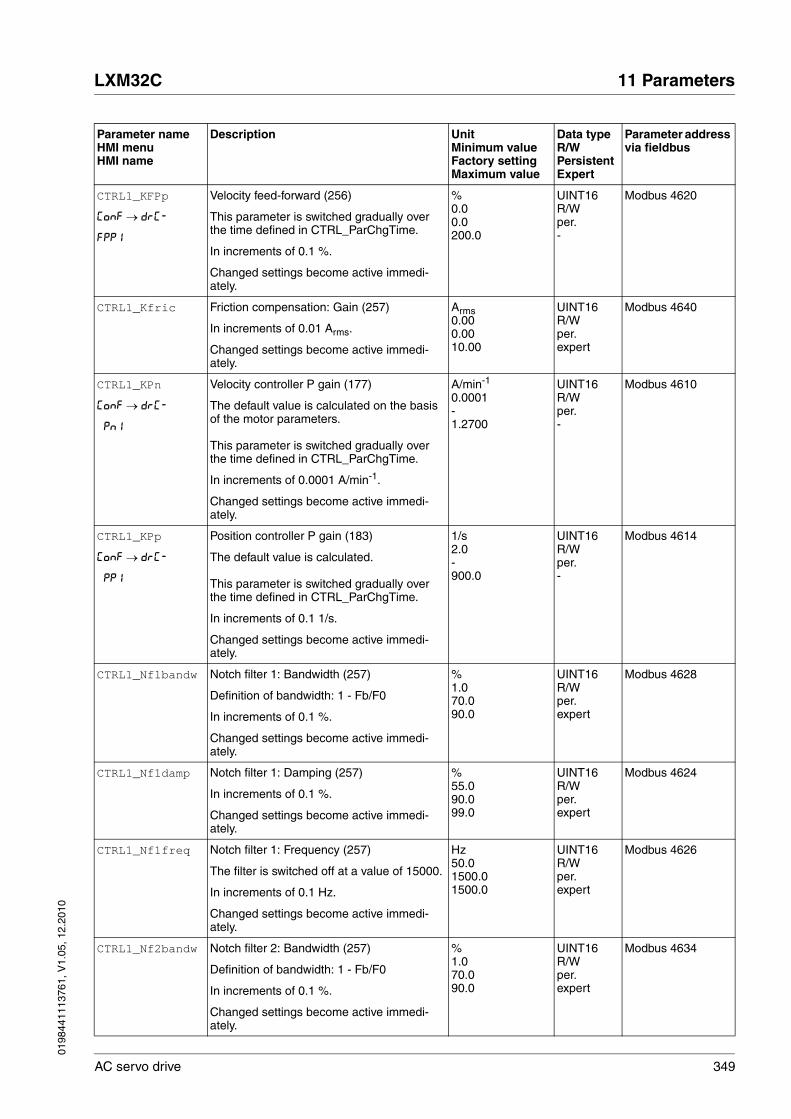
0198
4411
1376
1, V
1.05
, 12.
2010
LXM32C 11 Parameters
AC servo drive 349
CTRL1_KFPp
ConF → drC-
FPP1
Velocity feed-forward (256)
This parameter is switched gradually over the time defined in CTRL_ParChgTime.
In increments of 0.1 %.
Changed settings become active immedi-ately.
%0.00.0200.0
UINT16R/Wper.-
Modbus 4620
CTRL1_Kfric Friction compensation: Gain (257)
In increments of 0.01 Arms.
Changed settings become active immedi-ately.
Arms0.000.0010.00
UINT16R/Wper.expert
Modbus 4640
CTRL1_KPn
ConF → drC-
Pn1
Velocity controller P gain (177)
The default value is calculated on the basis of the motor parameters.
This parameter is switched gradually over the time defined in CTRL_ParChgTime.
In increments of 0.0001 A/min-1.
Changed settings become active immedi-ately.
A/min-1
0.0001-1.2700
UINT16R/Wper.-
Modbus 4610
CTRL1_KPp
ConF → drC-
PP1
Position controller P gain (183)
The default value is calculated.
This parameter is switched gradually over the time defined in CTRL_ParChgTime.
In increments of 0.1 1/s.
Changed settings become active immedi-ately.
1/s2.0-900.0
UINT16R/Wper.-
Modbus 4614
CTRL1_Nf1bandw Notch filter 1: Bandwidth (257)
Definition of bandwidth: 1 - Fb/F0
In increments of 0.1 %.
Changed settings become active immedi-ately.
%1.070.090.0
UINT16R/Wper.expert
Modbus 4628
CTRL1_Nf1damp Notch filter 1: Damping (257)
In increments of 0.1 %.
Changed settings become active immedi-ately.
%55.090.099.0
UINT16R/Wper.expert
Modbus 4624
CTRL1_Nf1freq Notch filter 1: Frequency (257)
The filter is switched off at a value of 15000.
In increments of 0.1 Hz.
Changed settings become active immedi-ately.
Hz50.01500.01500.0
UINT16R/Wper.expert
Modbus 4626
CTRL1_Nf2bandw Notch filter 2: Bandwidth (257)
Definition of bandwidth: 1 - Fb/F0
In increments of 0.1 %.
Changed settings become active immedi-ately.
%1.070.090.0
UINT16R/Wper.expert
Modbus 4634
Parameter nameHMI menuHMI name
Description UnitMinimum valueFactory settingMaximum value
Data typeR/WPersistentExpert
Parameter address via fieldbus
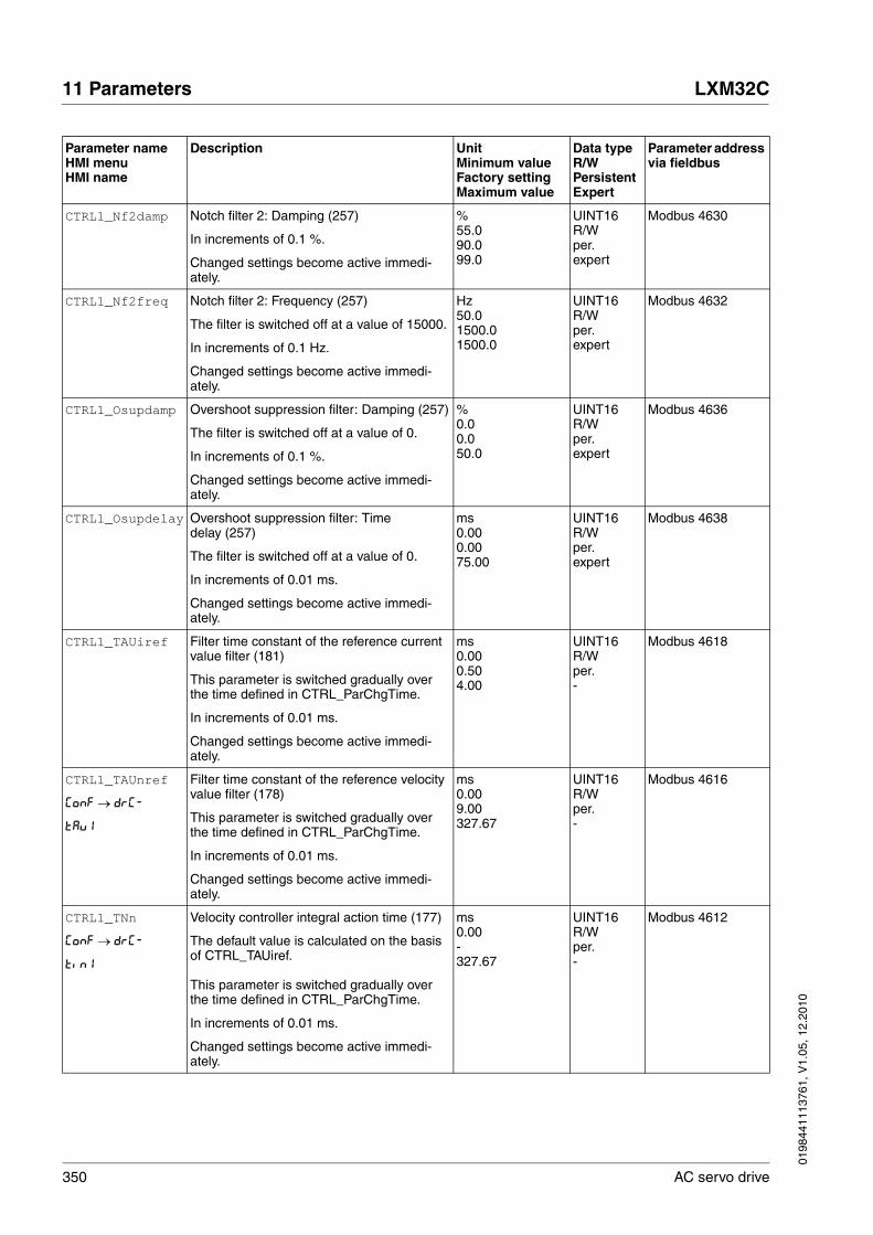
350 AC servo drive
11 Parameters LXM32C
0198
4411
1376
1, V
1.05
, 12.
2010
CTRL1_Nf2damp Notch filter 2: Damping (257)
In increments of 0.1 %.
Changed settings become active immedi-ately.
%55.090.099.0
UINT16R/Wper.expert
Modbus 4630
CTRL1_Nf2freq Notch filter 2: Frequency (257)
The filter is switched off at a value of 15000.
In increments of 0.1 Hz.
Changed settings become active immedi-ately.
Hz50.01500.01500.0
UINT16R/Wper.expert
Modbus 4632
CTRL1_Osupdamp Overshoot suppression filter: Damping (257)
The filter is switched off at a value of 0.
In increments of 0.1 %.
Changed settings become active immedi-ately.
%0.00.050.0
UINT16R/Wper.expert
Modbus 4636
CTRL1_Osupdelay Overshoot suppression filter: Time delay (257)
The filter is switched off at a value of 0.
In increments of 0.01 ms.
Changed settings become active immedi-ately.
ms0.000.0075.00
UINT16R/Wper.expert
Modbus 4638
CTRL1_TAUiref Filter time constant of the reference current value filter (181)
This parameter is switched gradually over the time defined in CTRL_ParChgTime.
In increments of 0.01 ms.
Changed settings become active immedi-ately.
ms0.000.504.00
UINT16R/Wper.-
Modbus 4618
CTRL1_TAUnref
ConF → drC-
tAu1
Filter time constant of the reference velocity value filter (178)
This parameter is switched gradually over the time defined in CTRL_ParChgTime.
In increments of 0.01 ms.
Changed settings become active immedi-ately.
ms0.009.00327.67
UINT16R/Wper.-
Modbus 4616
CTRL1_TNn
ConF → drC-
tin1
Velocity controller integral action time (177)
The default value is calculated on the basis of CTRL_TAUiref.
This parameter is switched gradually over the time defined in CTRL_ParChgTime.
In increments of 0.01 ms.
Changed settings become active immedi-ately.
ms0.00-327.67
UINT16R/Wper.-
Modbus 4612
Parameter nameHMI menuHMI name
Description UnitMinimum valueFactory settingMaximum value
Data typeR/WPersistentExpert
Parameter address via fieldbus

0198
4411
1376
1, V
1.05
, 12.
2010
LXM32C 11 Parameters
AC servo drive 351
CTRL2_KFPp
ConF → drC-
FPP2
Velocity feed-forward (258)
This parameter is switched gradually over the time defined in CTRL_ParChgTime.
In increments of 0.1 %.
Changed settings become active immedi-ately.
%0.00.0200.0
UINT16R/Wper.-
Modbus 4876
CTRL2_Kfric Friction compensation: Gain (258)
In increments of 0.01 Arms.
Changed settings become active immedi-ately.
Arms0.000.0010.00
UINT16R/Wper.expert
Modbus 4896
CTRL2_KPn
ConF → drC-
Pn2
Velocity controller P gain (177)
The default value is calculated on the basis of the motor parameters.
This parameter is switched gradually over the time defined in CTRL_ParChgTime.
In increments of 0.0001 A/min-1.
Changed settings become active immedi-ately.
A/min-1
0.0001-1.2700
UINT16R/Wper.-
Modbus 4866
CTRL2_KPp
ConF → drC-
PP2
Position controller P gain (183)
The default value is calculated.
This parameter is switched gradually over the time defined in CTRL_ParChgTime.
In increments of 0.1 1/s.
Changed settings become active immedi-ately.
1/s2.0-900.0
UINT16R/Wper.-
Modbus 4870
CTRL2_Nf1bandw Notch filter 1: Bandwidth (258)
Definition of bandwidth: 1 - Fb/F0
In increments of 0.1 %.
Changed settings become active immedi-ately.
%1.070.090.0
UINT16R/Wper.expert
Modbus 4884
CTRL2_Nf1damp Notch filter 1: Damping (258)
In increments of 0.1 %.
Changed settings become active immedi-ately.
%55.090.099.0
UINT16R/Wper.expert
Modbus 4880
CTRL2_Nf1freq Notch filter 1: Frequency (258)
The filter is switched off at a value of 15000.
In increments of 0.1 Hz.
Changed settings become active immedi-ately.
Hz50.01500.01500.0
UINT16R/Wper.expert
Modbus 4882
CTRL2_Nf2bandw Notch filter 2: Bandwidth (259)
Definition of bandwidth: 1 - Fb/F0
In increments of 0.1 %.
Changed settings become active immedi-ately.
%1.070.090.0
UINT16R/Wper.expert
Modbus 4890
Parameter nameHMI menuHMI name
Description UnitMinimum valueFactory settingMaximum value
Data typeR/WPersistentExpert
Parameter address via fieldbus

352 AC servo drive
11 Parameters LXM32C
0198
4411
1376
1, V
1.05
, 12.
2010
CTRL2_Nf2damp Notch filter 2: Damping (259)
In increments of 0.1 %.
Changed settings become active immedi-ately.
%55.090.099.0
UINT16R/Wper.expert
Modbus 4886
CTRL2_Nf2freq Notch filter 2: Frequency (259)
The filter is switched off at a value of 15000.
In increments of 0.1 Hz.
Changed settings become active immedi-ately.
Hz50.01500.01500.0
UINT16R/Wper.expert
Modbus 4888
CTRL2_Osupdamp Overshoot suppression filter: Damping (259)
The filter is switched off at a value of 0.
In increments of 0.1 %.
Changed settings become active immedi-ately.
%0.00.050.0
UINT16R/Wper.expert
Modbus 4892
CTRL2_Osupdelay Overshoot suppression filter: Time delay (259)
The filter is switched off at a value of 0.
In increments of 0.01 ms.
Changed settings become active immedi-ately.
ms0.000.0075.00
UINT16R/Wper.expert
Modbus 4894
CTRL2_TAUiref Filter time constant of the reference current value filter (181)
This parameter is switched gradually over the time defined in CTRL_ParChgTime.
In increments of 0.01 ms.
Changed settings become active immedi-ately.
ms0.000.504.00
UINT16R/Wper.-
Modbus 4874
CTRL2_TAUnref
ConF → drC-
tAu2
Filter time constant of the reference velocity value filter (179)
This parameter is switched gradually over the time defined in CTRL_ParChgTime.
In increments of 0.01 ms.
Changed settings become active immedi-ately.
ms0.009.00327.67
UINT16R/Wper.-
Modbus 4872
CTRL2_TNn
ConF → drC-
tin2
Velocity controller integral action time (177)
The default value is calculated on the basis of CTRL_TAUiref.
This parameter is switched gradually over the time defined in CTRL_ParChgTime.
In increments of 0.01 ms.
Changed settings become active immedi-ately.
ms0.00-327.67
UINT16R/Wper.-
Modbus 4868
Parameter nameHMI menuHMI name
Description UnitMinimum valueFactory settingMaximum value
Data typeR/WPersistentExpert
Parameter address via fieldbus

0198
4411
1376
1, V
1.05
, 12.
2010
LXM32C 11 Parameters
AC servo drive 353
DCbus_compat DC bus compatibility LXM32 and ATV32
0 / No DC bus or LXM32 only: DC bus not used or only LXM32 connected via the DC bus1 / DC bus with LXM32 and ATV32: LXM32 and ATV32 connected via the DC bus
NOTE: Connecting LXM32 drives and ATV32 drives via the DC bus may change the technical data.
Setting can only be changed if power stage is disabled.
Changed settings become active the next time the product is switched on.
-001
UINT16R/Wper.-
Modbus 1356
DCOMcontrol DriveCom control word
Refer to chapter Operation, Operating States, for bit coding information.Bit 0: Switch onBit 1: Enable Voltage Bit 2: Quick StopBit 3: Enable OperationBits 4 ... 6: Operating mode specificBit 7: Fault ResetBit 8: HaltBit 9: Change on setpointBits 10 ... 15: Reserved (must be 0)
Changed settings become active immedi-ately.
----
UINT16R/W--
Modbus 6914
DI_0_Debounce Debounce time of DI0
0 / No: No software debouncing1 / 0.25 ms: 0.25 ms2 / 0.50 ms: 0.50 ms3 / 0.75 ms: 0.75 ms4 / 1.00 ms: 1.00 ms5 / 1.25 ms: 1.25 ms6 / 1.50 ms: 1.50 ms
Setting can only be changed if power stage is disabled.
Changed settings become active immedi-ately.
-066
UINT16R/Wper.-
Modbus 2112
DI_1_Debounce Debounce time of DI1
0 / No: No software debouncing1 / 0.25 ms: 0.25 ms2 / 0.50 ms: 0.50 ms3 / 0.75 ms: 0.75 ms4 / 1.00 ms: 1.00 ms5 / 1.25 ms: 1.25 ms6 / 1.50 ms: 1.50 ms
Setting can only be changed if power stage is disabled.
Changed settings become active immedi-ately.
-066
UINT16R/Wper.-
Modbus 2114
Parameter nameHMI menuHMI name
Description UnitMinimum valueFactory settingMaximum value
Data typeR/WPersistentExpert
Parameter address via fieldbus

354 AC servo drive
11 Parameters LXM32C
0198
4411
1376
1, V
1.05
, 12.
2010
DI_2_Debounce Debounce time of DI2
0 / No: No software debouncing1 / 0.25 ms: 0.25 ms2 / 0.50 ms: 0.50 ms3 / 0.75 ms: 0.75 ms4 / 1.00 ms: 1.00 ms5 / 1.25 ms: 1.25 ms6 / 1.50 ms: 1.50 ms
Setting can only be changed if power stage is disabled.
Changed settings become active immedi-ately.
-066
UINT16R/Wper.-
Modbus 2116
DI_3_Debounce Debounce time of DI3
0 / No: No software debouncing1 / 0.25 ms: 0.25 ms2 / 0.50 ms: 0.50 ms3 / 0.75 ms: 0.75 ms4 / 1.00 ms: 1.00 ms5 / 1.25 ms: 1.25 ms6 / 1.50 ms: 1.50 ms
Setting can only be changed if power stage is disabled.
Changed settings become active immedi-ately.
-066
UINT16R/Wper.-
Modbus 2118
DI_4_Debounce Debounce time of DI4
0 / No: No software debouncing1 / 0.25 ms: 0.25 ms2 / 0.50 ms: 0.50 ms3 / 0.75 ms: 0.75 ms4 / 1.00 ms: 1.00 ms5 / 1.25 ms: 1.25 ms6 / 1.50 ms: 1.50 ms
Setting can only be changed if power stage is disabled.
Changed settings become active immedi-ately.
-066
UINT16R/Wper.-
Modbus 2120
DI_5_Debounce Debounce time of DI5
0 / No: No software debouncing1 / 0.25 ms: 0.25 ms2 / 0.50 ms: 0.50 ms3 / 0.75 ms: 0.75 ms4 / 1.00 ms: 1.00 ms5 / 1.25 ms: 1.25 ms6 / 1.50 ms: 1.50 ms
Setting can only be changed if power stage is disabled.
Changed settings become active immedi-ately.
-066
UINT16R/Wper.-
Modbus 2122
DPL_dmControl Drive Profile Lexium dmControl ----
UINT16R/W--
Modbus 6974
Parameter nameHMI menuHMI name
Description UnitMinimum valueFactory settingMaximum value
Data typeR/WPersistentExpert
Parameter address via fieldbus
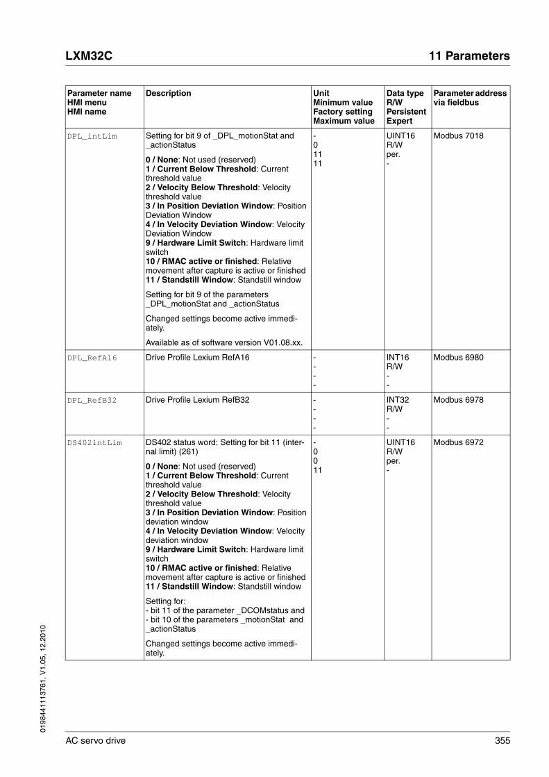
0198
4411
1376
1, V
1.05
, 12.
2010
LXM32C 11 Parameters
AC servo drive 355
DPL_intLim Setting for bit 9 of _DPL_motionStat and _actionStatus
0 / None: Not used (reserved)1 / Current Below Threshold: Current threshold value2 / Velocity Below Threshold: Velocity threshold value3 / In Position Deviation Window: Position Deviation Window4 / In Velocity Deviation Window: Velocity Deviation Window9 / Hardware Limit Switch: Hardware limit switch10 / RMAC active or finished: Relative movement after capture is active or finished11 / Standstill Window: Standstill window
Setting for bit 9 of the parameters _DPL_motionStat and _actionStatus
Changed settings become active immedi-ately.
Available as of software version V01.08.xx.
-01111
UINT16R/Wper.-
Modbus 7018
DPL_RefA16 Drive Profile Lexium RefA16 ----
INT16R/W--
Modbus 6980
DPL_RefB32 Drive Profile Lexium RefB32 ----
INT32R/W--
Modbus 6978
DS402intLim DS402 status word: Setting for bit 11 (inter-nal limit) (261)
0 / None: Not used (reserved)1 / Current Below Threshold: Current threshold value2 / Velocity Below Threshold: Velocity threshold value3 / In Position Deviation Window: Position deviation window4 / In Velocity Deviation Window: Velocity deviation window9 / Hardware Limit Switch: Hardware limit switch10 / RMAC active or finished: Relative movement after capture is active or finished11 / Standstill Window: Standstill window
Setting for: - bit 11 of the parameter _DCOMstatus and - bit 10 of the parameters _motionStat and _actionStatus
Changed settings become active immedi-ately.
-0011
UINT16R/Wper.-
Modbus 6972
Parameter nameHMI menuHMI name
Description UnitMinimum valueFactory settingMaximum value
Data typeR/WPersistentExpert
Parameter address via fieldbus

356 AC servo drive
11 Parameters LXM32C
0198
4411
1376
1, V
1.05
, 12.
2010
ENC1_adjustment Adjustment of absolute position of encoder 1 (164)
The value range depends on the encoder type.
Singleturn encoder: 0 ... max_pos_usr/rev. - 1
Singleturn encoder (shifted with parameter ShiftEncWorkRang): -(max_pos_usr/rev)/2 ... (max_pos_usr/rev.)/2 -1
Multiturn encoder: 0 ... (4096 * max_pos_usr/rev.) -1
Multiturn encoder (shifted with parameter ShiftEncWorkRang): -2048 * max_pos_usr/rev ... (2048 * max_pos_usr/rev.) -1
max_pos_usr/rev.: Maximum user-defined position for one encoder turn. This value is 16384 with the default scaling.
NOTE: * If processing is to be performed with inver-sion of the direction of movement, this must be set before the encoder position is adjusted.* After the write access, a wait time of at least 1 second is required before the drive is switched off.* Changing this value also changes the posi-tion of the virtual index pulse and the index pulse for the encoder simulation.
Changed settings become active the next time the product is switched on.
usr_p---
INT32R/W--
Modbus 1324
ErrorResp_Flt_AC
Error response to missing mains phase (290)
1 / Error Class 1: Error class 12 / Error Class 2: Error class 23 / Error Class 3: Error class 3
Setting can only be changed if power stage is disabled.
Changed settings become active the next time the power stage is enabled.
-123
UINT16R/Wper.-
Modbus 1300
ErrorResp_I2tRES
Error response to 100% I2t braking resistor
0 / Warning: Warning (error class 0)1 / Error Class 1: Error class 12 / Error Class 2: Error class 2
Setting can only be changed if power stage is disabled.
Changed settings become active the next time the power stage is enabled.
-002
UINT16R/Wper.-
Modbus 1348
Parameter nameHMI menuHMI name
Description UnitMinimum valueFactory settingMaximum value
Data typeR/WPersistentExpert
Parameter address via fieldbus
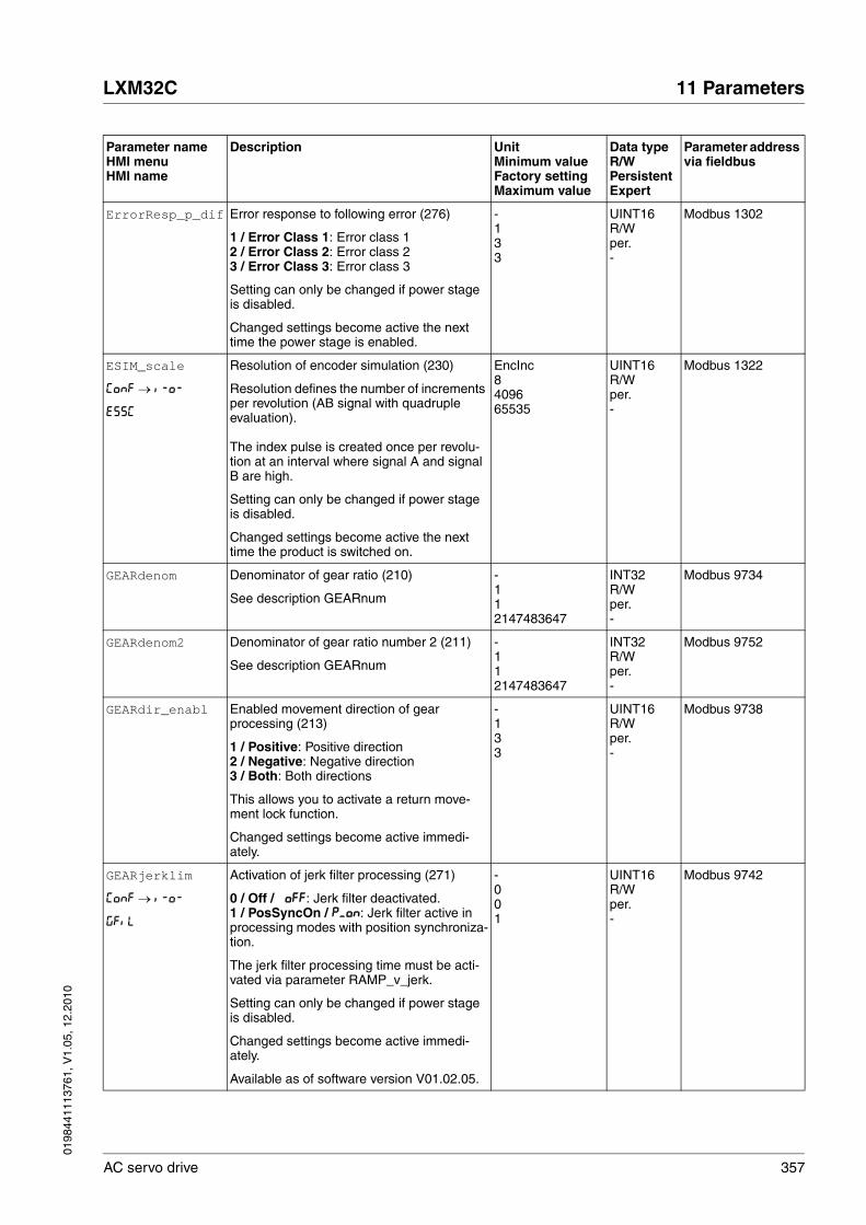
0198
4411
1376
1, V
1.05
, 12.
2010
LXM32C 11 Parameters
AC servo drive 357
ErrorResp_p_dif Error response to following error (276)
1 / Error Class 1: Error class 12 / Error Class 2: Error class 23 / Error Class 3: Error class 3
Setting can only be changed if power stage is disabled.
Changed settings become active the next time the power stage is enabled.
-133
UINT16R/Wper.-
Modbus 1302
ESIM_scale
ConF → i-o-
ESSC
Resolution of encoder simulation (230)
Resolution defines the number of increments per revolution (AB signal with quadruple evaluation).
The index pulse is created once per revolu-tion at an interval where signal A and signal B are high.
Setting can only be changed if power stage is disabled.
Changed settings become active the next time the product is switched on.
EncInc8409665535
UINT16R/Wper.-
Modbus 1322
GEARdenom Denominator of gear ratio (210)
See description GEARnum
-112147483647
INT32R/Wper.-
Modbus 9734
GEARdenom2 Denominator of gear ratio number 2 (211)
See description GEARnum
-112147483647
INT32R/Wper.-
Modbus 9752
GEARdir_enabl Enabled movement direction of gear processing (213)
1 / Positive: Positive direction2 / Negative: Negative direction3 / Both: Both directions
This allows you to activate a return move-ment lock function.
Changed settings become active immedi-ately.
-133
UINT16R/Wper.-
Modbus 9738
GEARjerklim
ConF → i-o-
GFiL
Activation of jerk filter processing (271)
0 / Off / oFF: Jerk filter deactivated.1 / PosSyncOn / P_on: Jerk filter active in processing modes with position synchroniza-tion.
The jerk filter processing time must be acti-vated via parameter RAMP_v_jerk.
Setting can only be changed if power stage is disabled.
Changed settings become active immedi-ately.
Available as of software version V01.02.05.
-001
UINT16R/Wper.-
Modbus 9742
Parameter nameHMI menuHMI name
Description UnitMinimum valueFactory settingMaximum value
Data typeR/WPersistentExpert
Parameter address via fieldbus

358 AC servo drive
11 Parameters LXM32C
0198
4411
1376
1, V
1.05
, 12.
2010
GEARnum Numerator of gear ratio (210)
GEARnum---------------------- = Gear ratioGEARdenom
The new gear ratio is applied when the numerator value is supplied.
Changed settings become active immedi-ately.
--214748364812147483647
INT32R/Wper.-
Modbus 9736
GEARnum2 Numerator of gear ratio number 2 (211)
GEARnum2---------------------- = Gear ratioGEARdenom2
The new gear ratio is applied when the numerator value is supplied.
Changed settings become active immedi-ately.
--214748364812147483647
INT32R/Wper.-
Modbus 9754
GEARposChgMode Consideration of position changes with inac-tive power stage (212)
0 / Off: Position changes in states with inac-tive power stage are discarded.1 / On: Position changes in states with inac-tive power stage are considered.
This setting has an effect only if gear processing is started in the mode 'Synchro-nization with compensation movement'.
Changed settings become active the next time the power stage is enabled.
-001
UINT16R/Wper.-
Modbus 9750
GEARratio
ConF → i-o-
GFAC
Selection of special gear ratios (210)
0 / Gear Factor / FAct: Usage of gear ratio adjusted with GEARnum/GEARdenom1 / 200 / 200: 2002 / 400 / 400: 4003 / 500 / 500: 5004 / 1000 / 1000: 10005 / 2000 / 2000: 20006 / 4000 / 4000: 40007 / 5000 / 5000: 50008 / 10000 / 10.00: 100009 / 4096 / 4096: 409610 / 8192 / 8192: 819211 / 16384 / 16.38: 16384
A change of the reference value by the spec-ified value causes one motor revolution.
Changed settings become active immedi-ately.
-0011
UINT16R/Wper.-
Modbus 9740
HMIDispPara
Mon
SuPV
HMI display when motor moves
0 / OperatingState / StAt: Operating state1 / v_act / VAct: Actual motor velocity2 / I_act / iAct: Actual motor current
Changed settings become active immedi-ately.
-002
UINT16R/Wper.-
Modbus 14852
Parameter nameHMI menuHMI name
Description UnitMinimum valueFactory settingMaximum value
Data typeR/WPersistentExpert
Parameter address via fieldbus

0198
4411
1376
1, V
1.05
, 12.
2010
LXM32C 11 Parameters
AC servo drive 359
HMIlocked Lock HMI (192)
0 / Not Locked / nLoc: HMI not locked1 / Locked / Loc: HMI locked
The following functions can no longer be started when the HMI is locked:- Parameter change- Jog- Autotuning- Fault Reset
Changed settings become active immedi-ately.
-001
UINT16R/Wper.-
Modbus 14850
InvertDirOf-Count
Inversion of direction of counting at PTI interface (209)
0 / Inversion Off: Inversion of direction of counting is off1 / Inversion On: Inversion of direction of counting is on
Changed settings become active immedi-ately.
-001
UINT16R/Wper.-
Modbus 2062
InvertDirOfMove
ConF → ACG-
inMo
Inversion of direction of movement (163)
0 / Inversion Off / oFF: Inversion of direc-tion of movement is off1 / Inversion On / on: Inversion of direc-tion of movement is on
The limit switch which is reached with a movement in positive direction must be con-nected to the positive limit switch input and vice versa.
Setting can only be changed if power stage is disabled.
Changed settings become active the next time the product is switched on.
-001
UINT16R/Wper.-
Modbus 1560
IO_AutoEnable
ConF → ACG-
ioAE
Enabling the power stage at PowerOn
0 / Off / oFF: After start-up, a rising edge with the signal input function Enable enables the power stage1 / On / on: After start-up, an active signal input with signal input function Enable ena-bles the power stage2 / AutoOn / Auto: After start-up, the power stage is automatically enabled
Changed settings become active the next time the power stage is enabled.
-002
UINT16R/Wper.-
Modbus 1292
Parameter nameHMI menuHMI name
Description UnitMinimum valueFactory settingMaximum value
Data typeR/WPersistentExpert
Parameter address via fieldbus

360 AC servo drive
11 Parameters LXM32C
0198
4411
1376
1, V
1.05
, 12.
2010
IO_DQ_set Setting the digital outputs directly
Write access to output bits is only active if the signal pin is available as an output and if the function of the output was set to 'Availa-ble as required'.
Coding of the individual signals: Bit 0: DQ0Bit 1: DQ1Bit 2: DQ2Bit 3: DQ3Bit 4: DQ4
----
UINT16R/W--
Modbus 2082
IO_GEARmethod
ConF → ACG-
ioGM
Processing mode for operating mode Elec-tronic Gear (211)
1 / Position Synchronization Immediate / PoiM: Position synchronization without com-pensation movement2 / Position Synchronization Compen-sated / Poco: Position synchronization with compensation movement3 / Velocity Synchronization / VELo: Veloc-ity synchronization
Changed settings become active the next time the motor moves.
-113
UINT16R/Wper.-
Modbus 1326
IO_I_limit
ConF → i-o-
iLiM
Current limitation via input (269)
A current limit can be activated via a digital input.
In increments of 0.01 Arms.
Changed settings become active immedi-ately.
Arms0.000.20300.00
UINT16R/Wper.-
Modbus 1614
IO_JOGmethod
ConF → ACG-
ioJG
Selection of jog method (204)
0 / Continuous Movement / coMo: Jog with continuous movement1 / Step Movement / StMo: Jog with step movement
Changed settings become active the next time the motor moves.
-001
UINT16R/Wper.-
Modbus 1328
IO_ModeSwitch
ConF → ACG-
ioMS
Operating mode for signal input function Operating Mode Switch (199)
0 / None / nonE: None1 / Profile Torque / torq: Profile Torque2 / Profile Velocity / VELP: Profile Velocity3 / Electronic Gear / GEAr: Electronic Gear
Changed settings become active immedi-ately.
-003
UINT16R/Wper.-
Modbus 1630
IO_v_limit Velocity limitation via input (267)
A velocity limitation can be activated via a digital input.NOTE: In operating mode Profile Torque, the minimum velocity is internally limited to 100 min-1.
Changed settings become active immedi-ately.
usr_v1102147483647
UINT32R/Wper.-
Modbus 1596
Parameter nameHMI menuHMI name
Description UnitMinimum valueFactory settingMaximum value
Data typeR/WPersistentExpert
Parameter address via fieldbus

0198
4411
1376
1, V
1.05
, 12.
2010
LXM32C 11 Parameters
AC servo drive 361
IOdefaultMode
ConF → ACG-
io-M
Operating mode (198)
0 / None / nonE: None1 / Profile Torque / torq: Profile Torque2 / Profile Velocity / VELP: Profile Velocity3 / Electronic Gear / GEAr: Electronic Gear5 / Jog / JoG: Jog
Setting can only be changed if power stage is disabled.
Changed settings become active the next time the product is switched on.
-055
UINT16R/Wper.-
Modbus 1286
IOfunct_DI0
ConF → i-o-
di0
Function Input DI0 (234)
1 / Freely Available / nonE: Available as required2 / Fault Reset / FrES: Fault reset after error3 / Enable / EnAb: Enables the power stage4 / Halt / hALt: Halt6 / Current Limitation / iLiM: Limits the cur-rent to parameter value7 / Zero Clamp / CLMP: Zero clamping8 / Velocity Limitation / VLiM: Limits the velocity to parameter value9 / Jog Positive / JoGP: Jog: Moves in posi-tive direction10 / Jog Negative / JoGn: Jog: Moves in negative direction11 / Jog Fast/Slow / JoGF: Jog: Switches between slow and fast movement12 / Gear Ratio Switch / GrAt: Electronic Gear: Switches between two gear ratios19 / Gear Offset 1 / GoF1: Electronic Gear: Adds first gear offset20 / Gear Offset 2 / GoF2: Electronic Gear: Adds second gear offset21 / Reference Switch (REF) / rEF: Refer-ence switch22 / Positive Limit Switch (LIMP) / LiMP: Positive limit switch23 / Negative Limit Switch (LIMN) / LiMn: Negative limit switch24 / Switch Controller Parameter Set / CPAr: Switches controller parameter set25 / Inversion AI1 / A1iV: Inverts analog input AI126 / Inversion AI2 / A2iV: Inverts analog input AI227 / Operating Mode Switch / MSWt: Switches operating mode28 / Velocity Controller Integral Off / tnoF: Switches off velocity controller integral term
Setting can only be changed if power stage is disabled.
Changed settings become active the next time the product is switched on.
----
UINT16R/Wper.-
Modbus 1794
Parameter nameHMI menuHMI name
Description UnitMinimum valueFactory settingMaximum value
Data typeR/WPersistentExpert
Parameter address via fieldbus

362 AC servo drive
11 Parameters LXM32C
0198
4411
1376
1, V
1.05
, 12.
2010
IOfunct_DI1
ConF → i-o-
di1
Function Input DI1 (235)
1 / Freely Available / nonE: Available as required2 / Fault Reset / FrES: Fault reset after error3 / Enable / EnAb: Enables the power stage4 / Halt / hALt: Halt6 / Current Limitation / iLiM: Limits the cur-rent to parameter value7 / Zero Clamp / CLMP: Zero clamping8 / Velocity Limitation / VLiM: Limits the velocity to parameter value9 / Jog Positive / JoGP: Jog: Moves in posi-tive direction10 / Jog Negative / JoGn: Jog: Moves in negative direction11 / Jog Fast/Slow / JoGF: Jog: Switches between slow and fast movement12 / Gear Ratio Switch / GrAt: Electronic Gear: Switches between two gear ratios19 / Gear Offset 1 / GoF1: Electronic Gear: Adds first gear offset20 / Gear Offset 2 / GoF2: Electronic Gear: Adds second gear offset21 / Reference Switch (REF) / rEF: Refer-ence switch22 / Positive Limit Switch (LIMP) / LiMP: Positive limit switch23 / Negative Limit Switch (LIMN) / LiMn: Negative limit switch24 / Switch Controller Parameter Set / CPAr: Switches controller parameter set25 / Inversion AI1 / A1iV: Inverts analog input AI126 / Inversion AI2 / A2iV: Inverts analog input AI227 / Operating Mode Switch / MSWt: Switches operating mode28 / Velocity Controller Integral Off / tnoF: Switches off velocity controller integral term
Setting can only be changed if power stage is disabled.
Changed settings become active the next time the product is switched on.
----
UINT16R/Wper.-
Modbus 1796
Parameter nameHMI menuHMI name
Description UnitMinimum valueFactory settingMaximum value
Data typeR/WPersistentExpert
Parameter address via fieldbus
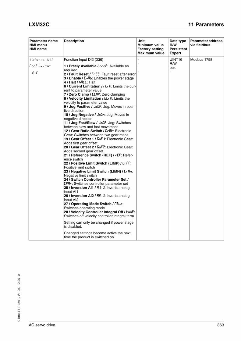
0198
4411
1376
1, V
1.05
, 12.
2010
LXM32C 11 Parameters
AC servo drive 363
IOfunct_DI2
ConF → i-o-
di2
Function Input DI2 (236)
1 / Freely Available / nonE: Available as required2 / Fault Reset / FrES: Fault reset after error3 / Enable / EnAb: Enables the power stage4 / Halt / hALt: Halt6 / Current Limitation / iLiM: Limits the cur-rent to parameter value7 / Zero Clamp / CLMP: Zero clamping8 / Velocity Limitation / VLiM: Limits the velocity to parameter value9 / Jog Positive / JoGP: Jog: Moves in posi-tive direction10 / Jog Negative / JoGn: Jog: Moves in negative direction11 / Jog Fast/Slow / JoGF: Jog: Switches between slow and fast movement12 / Gear Ratio Switch / GrAt: Electronic Gear: Switches between two gear ratios19 / Gear Offset 1 / GoF1: Electronic Gear: Adds first gear offset20 / Gear Offset 2 / GoF2: Electronic Gear: Adds second gear offset21 / Reference Switch (REF) / rEF: Refer-ence switch22 / Positive Limit Switch (LIMP) / LiMP: Positive limit switch23 / Negative Limit Switch (LIMN) / LiMn: Negative limit switch24 / Switch Controller Parameter Set / CPAr: Switches controller parameter set25 / Inversion AI1 / A1iV: Inverts analog input AI126 / Inversion AI2 / A2iV: Inverts analog input AI227 / Operating Mode Switch / MSWt: Switches operating mode28 / Velocity Controller Integral Off / tnoF: Switches off velocity controller integral term
Setting can only be changed if power stage is disabled.
Changed settings become active the next time the product is switched on.
----
UINT16R/Wper.-
Modbus 1798
Parameter nameHMI menuHMI name
Description UnitMinimum valueFactory settingMaximum value
Data typeR/WPersistentExpert
Parameter address via fieldbus

364 AC servo drive
11 Parameters LXM32C
0198
4411
1376
1, V
1.05
, 12.
2010
IOfunct_DI3
ConF → i-o-
di3
Function Input DI3 (237)
1 / Freely Available / nonE: Available as required2 / Fault Reset / FrES: Fault reset after error3 / Enable / EnAb: Enables the power stage4 / Halt / hALt: Halt6 / Current Limitation / iLiM: Limits the cur-rent to parameter value7 / Zero Clamp / CLMP: Zero clamping8 / Velocity Limitation / VLiM: Limits the velocity to parameter value9 / Jog Positive / JoGP: Jog: Moves in posi-tive direction10 / Jog Negative / JoGn: Jog: Moves in negative direction11 / Jog Fast/Slow / JoGF: Jog: Switches between slow and fast movement12 / Gear Ratio Switch / GrAt: Electronic Gear: Switches between two gear ratios19 / Gear Offset 1 / GoF1: Electronic Gear: Adds first gear offset20 / Gear Offset 2 / GoF2: Electronic Gear: Adds second gear offset21 / Reference Switch (REF) / rEF: Refer-ence switch22 / Positive Limit Switch (LIMP) / LiMP: Positive limit switch23 / Negative Limit Switch (LIMN) / LiMn: Negative limit switch24 / Switch Controller Parameter Set / CPAr: Switches controller parameter set25 / Inversion AI1 / A1iV: Inverts analog input AI126 / Inversion AI2 / A2iV: Inverts analog input AI227 / Operating Mode Switch / MSWt: Switches operating mode28 / Velocity Controller Integral Off / tnoF: Switches off velocity controller integral term
Setting can only be changed if power stage is disabled.
Changed settings become active the next time the product is switched on.
----
UINT16R/Wper.-
Modbus 1800
Parameter nameHMI menuHMI name
Description UnitMinimum valueFactory settingMaximum value
Data typeR/WPersistentExpert
Parameter address via fieldbus

0198
4411
1376
1, V
1.05
, 12.
2010
LXM32C 11 Parameters
AC servo drive 365
IOfunct_DI4
ConF → i-o-
di4
Function Input DI4 (238)
1 / Freely Available / nonE: Available as required2 / Fault Reset / FrES: Fault reset after error3 / Enable / EnAb: Enables the power stage4 / Halt / hALt: Halt6 / Current Limitation / iLiM: Limits the cur-rent to parameter value7 / Zero Clamp / CLMP: Zero clamping8 / Velocity Limitation / VLiM: Limits the velocity to parameter value9 / Jog Positive / JoGP: Jog: Moves in posi-tive direction10 / Jog Negative / JoGn: Jog: Moves in negative direction11 / Jog Fast/Slow / JoGF: Jog: Switches between slow and fast movement12 / Gear Ratio Switch / GrAt: Electronic Gear: Switches between two gear ratios19 / Gear Offset 1 / GoF1: Electronic Gear: Adds first gear offset20 / Gear Offset 2 / GoF2: Electronic Gear: Adds second gear offset21 / Reference Switch (REF) / rEF: Refer-ence switch22 / Positive Limit Switch (LIMP) / LiMP: Positive limit switch23 / Negative Limit Switch (LIMN) / LiMn: Negative limit switch24 / Switch Controller Parameter Set / CPAr: Switches controller parameter set25 / Inversion AI1 / A1iV: Inverts analog input AI126 / Inversion AI2 / A2iV: Inverts analog input AI227 / Operating Mode Switch / MSWt: Switches operating mode28 / Velocity Controller Integral Off / tnoF: Switches off velocity controller integral term
Setting can only be changed if power stage is disabled.
Changed settings become active the next time the product is switched on.
----
UINT16R/Wper.-
Modbus 1802
Parameter nameHMI menuHMI name
Description UnitMinimum valueFactory settingMaximum value
Data typeR/WPersistentExpert
Parameter address via fieldbus

366 AC servo drive
11 Parameters LXM32C
0198
4411
1376
1, V
1.05
, 12.
2010
IOfunct_DI5
ConF → i-o-
di5
Function Input DI5 (239)
1 / Freely Available / nonE: Available as required2 / Fault Reset / FrES: Fault reset after error3 / Enable / EnAb: Enables the power stage4 / Halt / hALt: Halt6 / Current Limitation / iLiM: Limits the cur-rent to parameter value7 / Zero Clamp / CLMP: Zero clamping8 / Velocity Limitation / VLiM: Limits the velocity to parameter value9 / Jog Positive / JoGP: Jog: Moves in posi-tive direction10 / Jog Negative / JoGn: Jog: Moves in negative direction11 / Jog Fast/Slow / JoGF: Jog: Switches between slow and fast movement12 / Gear Ratio Switch / GrAt: Electronic Gear: Switches between two gear ratios19 / Gear Offset 1 / GoF1: Electronic Gear: Adds first gear offset20 / Gear Offset 2 / GoF2: Electronic Gear: Adds second gear offset21 / Reference Switch (REF) / rEF: Refer-ence switch22 / Positive Limit Switch (LIMP) / LiMP: Positive limit switch23 / Negative Limit Switch (LIMN) / LiMn: Negative limit switch24 / Switch Controller Parameter Set / CPAr: Switches controller parameter set25 / Inversion AI1 / A1iV: Inverts analog input AI126 / Inversion AI2 / A2iV: Inverts analog input AI227 / Operating Mode Switch / MSWt: Switches operating mode28 / Velocity Controller Integral Off / tnoF: Switches off velocity controller integral term
Setting can only be changed if power stage is disabled.
Changed settings become active the next time the product is switched on.
----
UINT16R/Wper.-
Modbus 1804
Parameter nameHMI menuHMI name
Description UnitMinimum valueFactory settingMaximum value
Data typeR/WPersistentExpert
Parameter address via fieldbus

0198
4411
1376
1, V
1.05
, 12.
2010
LXM32C 11 Parameters
AC servo drive 367
IOfunct_DQ0
ConF → i-o-
do0
Function Output DQ0 (240)
1 / Freely Available / nonE: Available as required2 / No Fault / nFLt: Signals operating states Ready To Switch On, Switched On and Operation Enable3 / Active / Acti: Signals operating state Operation Enable5 / In Position Deviation Window / in-P: Position deviation is within window6 / In Velocity Deviation Window / in-V: Velocity deviation is within window7 / Velocity Below Threshold / Vthr: Motor velocity below threshold8 / Current Below Threshold / ithr: Motor current below threshold9 / Halt Acknowledge / hALt: Halt acknowl-edgement13 / Motor Standstill / MStd: Motor at a standstill14 / Selected Error / SErr: One of the selected errors is active16 / Selected Warning / SWrn: One of the selected warnings is active
Setting can only be changed if power stage is disabled.
Changed settings become active the next time the product is switched on.
----
UINT16R/Wper.-
Modbus 1810
IOfunct_DQ1
ConF → i-o-
do1
Function Output DQ1 (241)
1 / Freely Available / nonE: Available as required2 / No Fault / nFLt: Signals operating states Ready To Switch On, Switched On and Operation Enable3 / Active / Acti: Signals operating state Operation Enable5 / In Position Deviation Window / in-P: Position deviation is within window6 / In Velocity Deviation Window / in-V: Velocity deviation is within window7 / Velocity Below Threshold / Vthr: Motor velocity below threshold8 / Current Below Threshold / ithr: Motor current below threshold9 / Halt Acknowledge / hALt: Halt acknowl-edgement13 / Motor Standstill / MStd: Motor at a standstill14 / Selected Error / SErr: One of the selected errors is active16 / Selected Warning / SWrn: One of the selected warnings is active
Setting can only be changed if power stage is disabled.
Changed settings become active the next time the product is switched on.
----
UINT16R/Wper.-
Modbus 1812
Parameter nameHMI menuHMI name
Description UnitMinimum valueFactory settingMaximum value
Data typeR/WPersistentExpert
Parameter address via fieldbus

368 AC servo drive
11 Parameters LXM32C
0198
4411
1376
1, V
1.05
, 12.
2010
IOfunct_DQ2
ConF → i-o-
do2
Function Output DQ2 (241)
1 / Freely Available / nonE: Available as required2 / No Fault / nFLt: Signals operating states Ready To Switch On, Switched On and Operation Enable3 / Active / Acti: Signals operating state Operation Enable5 / In Position Deviation Window / in-P: Position deviation is within window6 / In Velocity Deviation Window / in-V: Velocity deviation is within window7 / Velocity Below Threshold / Vthr: Motor velocity below threshold8 / Current Below Threshold / ithr: Motor current below threshold9 / Halt Acknowledge / hALt: Halt acknowl-edgement13 / Motor Standstill / MStd: Motor at a standstill14 / Selected Error / SErr: One of the selected errors is active16 / Selected Warning / SWrn: One of the selected warnings is active
Setting can only be changed if power stage is disabled.
Changed settings become active the next time the product is switched on.
----
UINT16R/Wper.-
Modbus 1814
IOfunct_DQ3
ConF → i-o-
do3
Function Output DQ3 (242)
1 / Freely Available / nonE: Available as required2 / No Fault / nFLt: Signals operating states Ready To Switch On, Switched On and Operation Enable3 / Active / Acti: Signals operating state Operation Enable5 / In Position Deviation Window / in-P: Position deviation is within window6 / In Velocity Deviation Window / in-V: Velocity deviation is within window7 / Velocity Below Threshold / Vthr: Motor velocity below threshold8 / Current Below Threshold / ithr: Motor current below threshold9 / Halt Acknowledge / hALt: Halt acknowl-edgement13 / Motor Standstill / MStd: Motor at a standstill14 / Selected Error / SErr: One of the selected errors is active16 / Selected Warning / SWrn: One of the selected warnings is active
Setting can only be changed if power stage is disabled.
Changed settings become active the next time the product is switched on.
----
UINT16R/Wper.-
Modbus 1816
Parameter nameHMI menuHMI name
Description UnitMinimum valueFactory settingMaximum value
Data typeR/WPersistentExpert
Parameter address via fieldbus

0198
4411
1376
1, V
1.05
, 12.
2010
LXM32C 11 Parameters
AC servo drive 369
IOfunct_DQ4
ConF → i-o-
do4
Function Output DQ4 (242)
1 / Freely Available / nonE: Available as required2 / No Fault / nFLt: Signals operating states Ready To Switch On, Switched On and Operation Enable3 / Active / Acti: Signals operating state Operation Enable5 / In Position Deviation Window / in-P: Position deviation is within window6 / In Velocity Deviation Window / in-V: Velocity deviation is within window7 / Velocity Below Threshold / Vthr: Motor velocity below threshold8 / Current Below Threshold / ithr: Motor current below threshold9 / Halt Acknowledge / hALt: Halt acknowl-edgement13 / Motor Standstill / MStd: Motor at a standstill14 / Selected Error / SErr: One of the selected errors is active16 / Selected Warning / SWrn: One of the selected warnings is active
Setting can only be changed if power stage is disabled.
Changed settings become active the next time the product is switched on.
----
UINT16R/Wper.-
Modbus 1818
IOsigLIMN Signal evaluation for negative limit switch (273)
0 / Inactive: Inactive1 / Normally closed: Normally closed NC2 / Normally open: Normally open NO
Setting can only be changed if power stage is disabled.
Changed settings become active the next time the power stage is enabled.
-012
UINT16R/Wper.-
Modbus 1566
IOsigLIMP Signal evaluation for positive limit switch (272)
0 / Inactive: Inactive1 / Normally closed: Normally closed NC2 / Normally open: Normally open NO
Setting can only be changed if power stage is disabled.
Changed settings become active the next time the power stage is enabled.
-012
UINT16R/Wper.-
Modbus 1568
Parameter nameHMI menuHMI name
Description UnitMinimum valueFactory settingMaximum value
Data typeR/WPersistentExpert
Parameter address via fieldbus

370 AC servo drive
11 Parameters LXM32C
0198
4411
1376
1, V
1.05
, 12.
2010
IOsigREF Signal evaluation for reference switch
1 / Normally Closed: Normally closed NC2 / Normally Open: Normally open NO
The reference switch is only active while a reference movement to the reference switch is processed.
Setting can only be changed if power stage is disabled.
Changed settings become active the next time the power stage is enabled.
-112
UINT16R/Wper.-
Modbus 1564
JOGstep Distance for step movement (204)
Changed settings become active the next time the motor moves.
usr_p1202147483647
INT32R/Wper.-
Modbus 10510
JOGtime Wait time for step movement (204)
Changed settings become active the next time the motor moves.
ms150032767
UINT16R/Wper.-
Modbus 10512
JOGv_fast
oP → JoG-
JGhi
Velocity for fast movement (203)
The adjustable value is internally limited to the current parameter setting in RAMP_v_max.
Changed settings become active immedi-ately.
usr_v11802147483647
UINT32R/Wper.-
Modbus 10506
JOGv_slow
oP → JoG-
JGLo
Velocity for slow movement (203)
The adjustable value is internally limited to the current parameter setting in RAMP_v_max.
Changed settings become active immedi-ately.
usr_v1602147483647
UINT32R/Wper.-
Modbus 10504
LIM_HaltReaction
ConF → ACG-
htyP
Halt option code (262)
1 / Deceleration Ramp / dEcE: Deceleration ramp3 / Torque Ramp / torq: Torque ramp
Type of deceleration for Halt.
Setting of deceleration ramp with parameter RAMP_v_dec.Setting of torque ramp with parameter LIM_I_maxHalt.
If a deceleration ramp is already active, the parameter cannot be written.
Changed settings become active immedi-ately.
-113
INT16R/Wper.-
Modbus 1582
Parameter nameHMI menuHMI name
Description UnitMinimum valueFactory settingMaximum value
Data typeR/WPersistentExpert
Parameter address via fieldbus
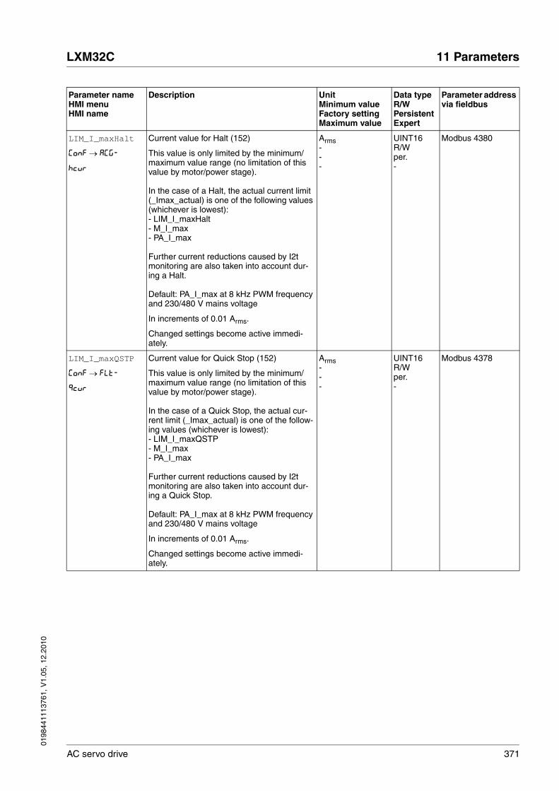
0198
4411
1376
1, V
1.05
, 12.
2010
LXM32C 11 Parameters
AC servo drive 371
LIM_I_maxHalt
ConF → ACG-
hcur
Current value for Halt (152)
This value is only limited by the minimum/maximum value range (no limitation of this value by motor/power stage).
In the case of a Halt, the actual current limit (_Imax_actual) is one of the following values (whichever is lowest):- LIM_I_maxHalt- M_I_max - PA_I_max
Further current reductions caused by I2t monitoring are also taken into account dur-ing a Halt.
Default: PA_I_max at 8 kHz PWM frequency and 230/480 V mains voltage
In increments of 0.01 Arms.
Changed settings become active immedi-ately.
Arms---
UINT16R/Wper.-
Modbus 4380
LIM_I_maxQSTP
ConF → FLt-
qcur
Current value for Quick Stop (152)
This value is only limited by the minimum/maximum value range (no limitation of this value by motor/power stage).
In the case of a Quick Stop, the actual cur-rent limit (_Imax_actual) is one of the follow-ing values (whichever is lowest):- LIM_I_maxQSTP- M_I_max- PA_I_max
Further current reductions caused by I2t monitoring are also taken into account dur-ing a Quick Stop.
Default: PA_I_max at 8 kHz PWM frequency and 230/480 V mains voltage
In increments of 0.01 Arms.
Changed settings become active immedi-ately.
Arms---
UINT16R/Wper.-
Modbus 4378
Parameter nameHMI menuHMI name
Description UnitMinimum valueFactory settingMaximum value
Data typeR/WPersistentExpert
Parameter address via fieldbus

372 AC servo drive
11 Parameters LXM32C
0198
4411
1376
1, V
1.05
, 12.
2010
LIM_QStopReact
ConF → FLt-
qtyP
Quick Stop option code (264)
6 / Deceleration ramp (Quick Stop) / dEc: Use deceleration ramp and remain in operat-ing state 7 Quick Stop7 / Torque ramp (Quick Stop) / tor: Use torque ramp and remain in operating state 7 Quick Stop
Type of deceleration for Quick Stop.
Setting of deceleration ramp with parameter RAMPquickstop.Setting of torque ramp with parameter LIM_I_maxQSTP.
If a deceleration ramp is already active, the parameter cannot be written.
Changed settings become active immedi-ately.
-667
INT16R/Wper.-
Modbus 1584
Mains_reactor Mains reactor
0 / No: No1 / Yes: Yes
Value 0: No mains reactor connected. The nominal power of the power stage is reduced.Value 1: A mains reactor is connected.
Setting can only be changed if power stage is disabled.
Changed settings become active immedi-ately.
-001
UINT16R/Wper.-
Modbus 1344
MBaddress
ConF → CoM-
MbAd
Modbus address
Valid addresses: 1 to 247
Changed settings become active the next time the product is switched on.
-11247
UINT16R/Wper.-
Modbus 5640
MBbaud
ConF → CoM-
Mbbd
Modbus baud rate
9600 / 9600 Baud / 9.6: 9600 Baud19200 / 19200 Baud / 19.2: 19200 Baud38400 / 38400 Baud / 38.4: 38400 Baud
Changed settings become active the next time the product is switched on.
-96001920038400
UINT16R/Wper.-
Modbus 5638
Mfb_ResRatio Transformation ratio
Setting can only be changed if power stage is disabled.
Changed settings become active the next time the product is switched on.
-0.3-1.0
UINT16R/W--
Modbus 23598
Parameter nameHMI menuHMI name
Description UnitMinimum valueFactory settingMaximum value
Data typeR/WPersistentExpert
Parameter address via fieldbus

0198
4411
1376
1, V
1.05
, 12.
2010
LXM32C 11 Parameters
AC servo drive 373
MON_ChkTime
ConF → i-o-
tthr
Monitoring of time window (279)
Adjustment of a time for monitoring of posi-tion deviation, speed deviation, speed value and current value. If the monitored value is in the permissible range during the adjusted time, the monitoring function delivers a posi-tive result.The status can be output via a parameteriza-ble output.
Changed settings become active immedi-ately.
ms009999
UINT16R/Wper.-
Modbus 1594
MON_commutat Commutation monitoring (289)
0 / Off: Commutation monitoring off1 / On: Commutation monitoring on
Setting can only be changed if power stage is disabled.
Changed settings become active the next time the power stage is enabled.
-011
UINT16R/Wper.-
Modbus 1290
MON_GroundFault Ground fault monitoring (292)
0 / Off: Ground fault monitoring off1 / On: Ground fault monitoring on
In exceptional cases, deactivation may be necessary, for example:- Long motor cablesDeactivate ground fault monitoring if it responds in an unwanted way.
Changed settings become active the next time the product is switched on.
-011
UINT16R/Wper.expert
Modbus 1312
MON_I_Threshold
ConF → i-o-
ithr
Monitoring of current threshold (284)
The system checks whether the drive is below the defined value during the period set with MON_ChkTime. The status can be output via a parameteriza-ble output.The parameter _Iq_act_rms is used as com-parison value.
In increments of 0.01 Arms.
Changed settings become active immedi-ately.
Arms0.000.20300.00
UINT16R/Wper.-
Modbus 1592
MON_IO_SelErr1 First number for the signal output function Selected Error
Changed settings become active immedi-ately.
-0065535
UINT16R/Wper.-
Modbus 15116
MON_IO_SelErr2 Second number for the signal output function Selected Error
Changed settings become active immedi-ately.
-0065535
UINT16R/Wper.-
Modbus 15118
MON_IO_SelWar1 First number for the signal output function Selected Warning
Changed settings become active immedi-ately.
-0065535
UINT16R/Wper.-
Modbus 15120
Parameter nameHMI menuHMI name
Description UnitMinimum valueFactory settingMaximum value
Data typeR/WPersistentExpert
Parameter address via fieldbus
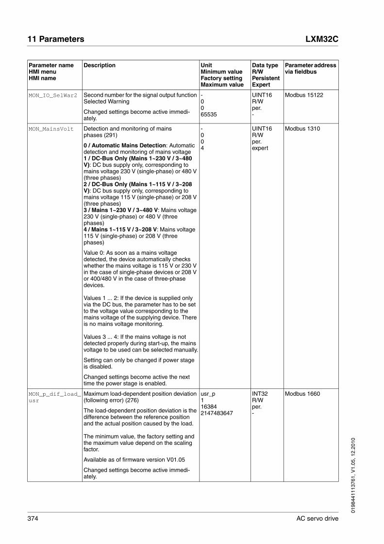
374 AC servo drive
11 Parameters LXM32C
0198
4411
1376
1, V
1.05
, 12.
2010
MON_IO_SelWar2 Second number for the signal output function Selected Warning
Changed settings become active immedi-ately.
-0065535
UINT16R/Wper.-
Modbus 15122
MON_MainsVolt Detection and monitoring of mains phases (291)
0 / Automatic Mains Detection: Automatic detection and monitoring of mains voltage1 / DC-Bus Only (Mains 1~230 V / 3~480 V): DC bus supply only, corresponding to mains voltage 230 V (single-phase) or 480 V (three phases)2 / DC-Bus Only (Mains 1~115 V / 3~208 V): DC bus supply only, corresponding to mains voltage 115 V (single-phase) or 208 V (three phases)3 / Mains 1~230 V / 3~480 V: Mains voltage 230 V (single-phase) or 480 V (three phases)4 / Mains 1~115 V / 3~208 V: Mains voltage 115 V (single-phase) or 208 V (three phases)
Value 0: As soon as a mains voltage detected, the device automatically checks whether the mains voltage is 115 V or 230 V in the case of single-phase devices or 208 V or 400/480 V in the case of three-phase devices.
Values 1 ... 2: If the device is supplied only via the DC bus, the parameter has to be set to the voltage value corresponding to the mains voltage of the supplying device. There is no mains voltage monitoring.
Values 3 ... 4: If the mains voltage is not detected properly during start-up, the mains voltage to be used can be selected manually.
Setting can only be changed if power stage is disabled.
Changed settings become active the next time the power stage is enabled.
-004
UINT16R/Wper.expert
Modbus 1310
MON_p_dif_load_usr
Maximum load-dependent position deviation (following error) (276)
The load-dependent position deviation is the difference between the reference position and the actual position caused by the load.
The minimum value, the factory setting and the maximum value depend on the scaling factor.
Available as of firmware version V01.05
Changed settings become active immedi-ately.
usr_p1163842147483647
INT32R/Wper.-
Modbus 1660
Parameter nameHMI menuHMI name
Description UnitMinimum valueFactory settingMaximum value
Data typeR/WPersistentExpert
Parameter address via fieldbus

0198
4411
1376
1, V
1.05
, 12.
2010
LXM32C 11 Parameters
AC servo drive 375
MON_p_dif_load Maximum load-dependent position deviation (following error) (276)
The load-dependent position deviation is the difference between the reference position and the actual position caused by the load.
The parameter MON_p_dif_load_usr allows you to enter the value in user-defined units.
In increments of 0.0001 revolution.
Changed settings become active immedi-ately.
revolution0.00011.0000200.0000
UINT32R/Wper.-
Modbus 1606
MON_p_dif_warn Maximum load-dependent position deviation (warning) (275)
100.0 % correspond to the maximum posi-tion deviation (following error) as specified by means of parameter MON_p_dif_load.
Changed settings become active immedi-ately.
%075100
UINT16R/Wper.-
Modbus 1618
MON_p_DiffWin_usr
Monitoring of position deviation (279)
The system checks whether the drive is within the defined deviation during the period set with MON_ChkTime. The status can be output via a parameteriza-ble output.
The minimum value, the factory setting and the maximum value depend on the scaling factor.
Available as of firmware version V01.05
Changed settings become active immedi-ately.
usr_p0162147483647
INT32R/Wper.-
Modbus 1662
MON_p_DiffWin Monitoring of position deviation (279)
The system checks whether the drive is within the defined deviation during the period set with MON_ChkTime. The status can be output via a parameteriza-ble output.
The parameter MON_p_DiffWin_usr allows you to enter the value in user-defined units.
In increments of 0.0001 revolution.
Changed settings become active immedi-ately.
revolution0.00000.00100.9999
UINT16R/Wper.-
Modbus 1586
Parameter nameHMI menuHMI name
Description UnitMinimum valueFactory settingMaximum value
Data typeR/WPersistentExpert
Parameter address via fieldbus

376 AC servo drive
11 Parameters LXM32C
0198
4411
1376
1, V
1.05
, 12.
2010
MON_p_win_usr Standstill window, permissible control devia-tion
The control deviation for the standstill win-dow time must be within this range for a standstill of the drive to be detected.
Processing of the standstill window must be activated via the parameter MON_p_winTime.
The minimum value, the factory setting and the maximum value depend on the scaling factor.
Changed settings become active immedi-ately.
usr_p0162147483647
INT32R/Wper.-
Modbus 1664
MON_p_win Standstill window, permissible control devia-tion
The control deviation for the standstill win-dow time must be within this range for a standstill of the drive to be detected.
Processing of the standstill window must be activated via the parameter MON_p_winTime.
The parameter MON_p_win_usr allows you to enter the value in user-defined units.
In increments of 0.0001 revolution.
Changed settings become active immedi-ately.
revolution0.00000.00103.2767
UINT16R/Wper.-
Modbus 1608
MON_p_winTime Standstill window, time
Value 0: Monitoring of standstill window deactivatedValue >0: Time in ms during which the con-trol deviation must be in the standstill win-dow
Changed settings become active immedi-ately.
ms0032767
UINT16R/Wper.-
Modbus 1610
MON_p_winTout Timeout time for standstill window monitor-ing
Value 0: Timeout monitoring deactivatedValue >0: Timeout time in ms
Standstill window processing values are set via MON_p_win and MON_p_winTime.
Time monitoring starts when the target posi-tion (reference position of position controller) is reached or when the profile generator has finished processing.
Changed settings become active immedi-ately.
ms0016000
UINT16R/Wper.-
Modbus 1612
Parameter nameHMI menuHMI name
Description UnitMinimum valueFactory settingMaximum value
Data typeR/WPersistentExpert
Parameter address via fieldbus

0198
4411
1376
1, V
1.05
, 12.
2010
LXM32C 11 Parameters
AC servo drive 377
MON_SW_Limits Monitoring of software limit switches
0 / None: Deactivated1 / SWLIMP: Activation of software limit switches positive direction2 / SWLIMN: Activation of software limit switches negative direction3 / SWLIMP+SWLIMN: Activation of soft-ware limit switches both directions
Monitoring of software limit switches only works in case of successful homing (ref_ok = 1).
Changed settings become active immedi-ately.
-003
UINT16R/Wper.-
Modbus 1542
MON_swLimN Negative position limit for software limit switch
Refer to description 'MON_swLimP'
Setting can only be changed if power stage is disabled.
Changed settings become active the next time the power stage is enabled.
usr_p--2147483648-
INT32R/Wper.-
Modbus 1546
MON_swLimP Positive position limit for software limit switch
If a user-defined value entered is outside of the permissible range, the limit switch limits are automatically set to the maximum user-defined value.
Setting can only be changed if power stage is disabled.
Changed settings become active the next time the power stage is enabled.
usr_p-2147483647-
INT32R/Wper.-
Modbus 1544
MON_tq_win Torque window, permissible deviation
The torque window can only be activated in operating mode Profile Torque.
In increments of 0.1 %.
Changed settings become active immedi-ately.
%0.03.03000.0
UINT16R/Wper.-
Modbus 1626
MON_tq_winTime Torque window, time
Value 0: Torque window monitoring deacti-vated
Changing the value causes a restart of torque monitoring.
NOTE: Torque window is only used in oper-ating mode Profile Torque.
Changed settings become active immedi-ately.
ms0016383
UINT16R/Wper.-
Modbus 1628
Parameter nameHMI menuHMI name
Description UnitMinimum valueFactory settingMaximum value
Data typeR/WPersistentExpert
Parameter address via fieldbus
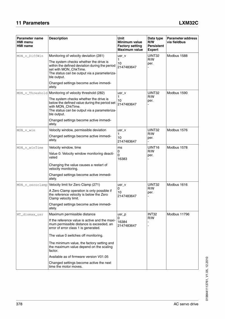
378 AC servo drive
11 Parameters LXM32C
0198
4411
1376
1, V
1.05
, 12.
2010
MON_v_DiffWin Monitoring of velocity deviation (281)
The system checks whether the drive is within the defined deviation during the period set with MON_ChkTime. The status can be output via a parameteriza-ble output.
Changed settings become active immedi-ately.
usr_v1102147483647
UINT32R/Wper.-
Modbus 1588
MON_v_Threshold Monitoring of velocity threshold (282)
The system checks whether the drive is below the defined value during the period set with MON_ChkTime. The status can be output via a parameteriza-ble output.
Changed settings become active immedi-ately.
usr_v1102147483647
UINT32R/Wper.-
Modbus 1590
MON_v_win Velocity window, permissible deviation
Changed settings become active immedi-ately.
usr_v1102147483647
UINT32R/Wper.-
Modbus 1576
MON_v_winTime Velocity window, time
Value 0: Velocity window monitoring deacti-vated
Changing the value causes a restart of velocity monitoring.
Changed settings become active immedi-ately.
ms0016383
UINT16R/Wper.-
Modbus 1578
MON_v_zeroclamp Velocity limit for Zero Clamp (271)
A Zero Clamp operation is only possible if the reference velocity is below the Zero Clamp velocity limit.
Changed settings become active immedi-ately.
usr_v0102147483647
UINT32R/Wper.-
Modbus 1616
MT_dismax_usr Maximum permissible distance
If the reference value is active and the maxi-mum permissible distance is exceeded, an error of error class 1 is generated.
The value 0 switches off monitoring.
The minimum value, the factory setting and the maximum value depend on the scaling factor.
Available as of firmware version V01.05
Changed settings become active the next time the motor moves.
usr_p0163842147483647
INT32R/W--
Modbus 11796
Parameter nameHMI menuHMI name
Description UnitMinimum valueFactory settingMaximum value
Data typeR/WPersistentExpert
Parameter address via fieldbus
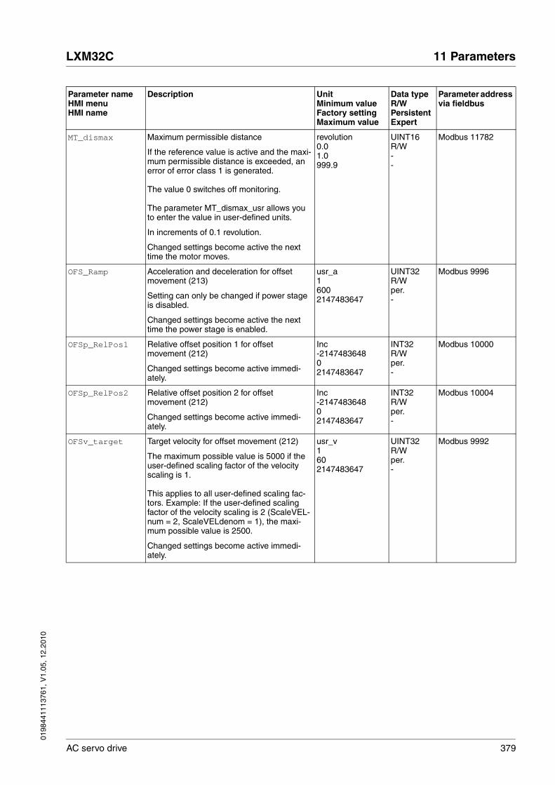
0198
4411
1376
1, V
1.05
, 12.
2010
LXM32C 11 Parameters
AC servo drive 379
MT_dismax Maximum permissible distance
If the reference value is active and the maxi-mum permissible distance is exceeded, an error of error class 1 is generated.
The value 0 switches off monitoring.
The parameter MT_dismax_usr allows you to enter the value in user-defined units.
In increments of 0.1 revolution.
Changed settings become active the next time the motor moves.
revolution0.01.0999.9
UINT16R/W--
Modbus 11782
OFS_Ramp Acceleration and deceleration for offset movement (213)
Setting can only be changed if power stage is disabled.
Changed settings become active the next time the power stage is enabled.
usr_a16002147483647
UINT32R/Wper.-
Modbus 9996
OFSp_RelPos1 Relative offset position 1 for offset movement (212)
Changed settings become active immedi-ately.
Inc-214748364802147483647
INT32R/Wper.-
Modbus 10000
OFSp_RelPos2 Relative offset position 2 for offset movement (212)
Changed settings become active immedi-ately.
Inc-214748364802147483647
INT32R/Wper.-
Modbus 10004
OFSv_target Target velocity for offset movement (212)
The maximum possible value is 5000 if the user-defined scaling factor of the velocity scaling is 1.
This applies to all user-defined scaling fac-tors. Example: If the user-defined scaling factor of the velocity scaling is 2 (ScaleVEL-num = 2, ScaleVELdenom = 1), the maxi-mum possible value is 2500.
Changed settings become active immedi-ately.
usr_v1602147483647
UINT32R/Wper.-
Modbus 9992
Parameter nameHMI menuHMI name
Description UnitMinimum valueFactory settingMaximum value
Data typeR/WPersistentExpert
Parameter address via fieldbus

380 AC servo drive
11 Parameters LXM32C
0198
4411
1376
1, V
1.05
, 12.
2010
PAR_CTRLreset
ConF → FCS-
rESC
Reset controller parameters
0 / No / no: No1 / Yes / yES: Yes
Reset of all controller parameters. The cur-rent controller parameters are recalculated on the basis of the motor data of the con-nected motor.
NOTE: Current and velocity limitations are not reset. Therefore, a user parameter reset is required.
NOTE: The new settings are not saved to the EEPROM.
Setting can only be changed if power stage is disabled.
Changed settings become active immedi-ately.
-001
UINT16R/W--
Modbus 1038
PAR_ScalingStart
Recalculation of parameters with user-defined units
The parameters with user-defined units can be recalculated with a changed scaling fac-tor.
Value 0: InactiveValue 1: Initialize recalculationValue 2: Start recalculation
Setting can only be changed if power stage is disabled.
Changed settings become active immedi-ately.
-002
UINT16R/W--
Modbus 1064
PAReeprSave Save parameter values to EEPROM
Value 1: Save all persistent parameters
The currently set parameters are saved to the non-volatile memory (EEPROM).The saving process is complete when the parameter is read and 0 is returned.
Changed settings become active immedi-ately.
----
UINT16R/W--
Modbus 1026
PARfactorySet
ConF → FCS-
rStF
Restore factory settings (default values)
No / no: NoYes / yES: Yes
All parameters are set to their default values, these are saved to the EEPROM.Restoring the factory settings is possible via the HMI or the commissioning software.The saving process is complete when the parameter is read and 0 is returned.
Setting can only be changed if power stage is disabled.
Changed settings become active the next time the product is switched on.
-0-1
R/W--
Parameter nameHMI menuHMI name
Description UnitMinimum valueFactory settingMaximum value
Data typeR/WPersistentExpert
Parameter address via fieldbus

0198
4411
1376
1, V
1.05
, 12.
2010
LXM32C 11 Parameters
AC servo drive 381
PARuserReset
ConF → FCS-
rESu
Reset user parameters
0 / No / no: No65535 / Yes / yES: Yes
Bit 0: Set persistent user and controller parameters to default valuesBits 1 ... 15: Reserved
All parameters are reset with the exception of:- Communication parameters- Inversion of direction of movement- Selection of signal type for position inter-face PTI- Defined operating mode- Settings of encoder simulation- Functions of digital inputs and outputs
NOTE: The new settings are not saved to the EEPROM.
Setting can only be changed if power stage is disabled.
Changed settings become active the next time the power stage is enabled.
-0-65535
UINT16R/W--
Modbus 1040
PP_ModeRangeLim Absolute movement beyond movement range
0 / NoAbsMoveAllowed: Absolute move-ment beyond movement range is not possi-ble1 / AbsMoveAllowed: Absolute movement beyond movement range is possible
Setting can only be changed if power stage is disabled.
Changed settings become active the next time the power stage is enabled.
-001
UINT16R/Wper.-
Modbus 8974
PP_OpmChgType Change to operating mode Profile Position during movements
0 / WithStandStill: Change with standstill1 / OnTheFly: Change without standstill
Setting can only be changed if power stage is disabled.
Changed settings become active the next time the power stage is enabled.
-001
UINT16R/Wper.-
Modbus 8978
Parameter nameHMI menuHMI name
Description UnitMinimum valueFactory settingMaximum value
Data typeR/WPersistentExpert
Parameter address via fieldbus
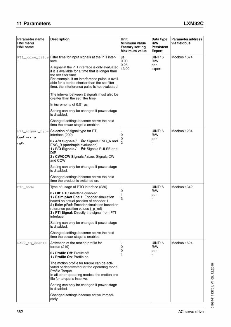
382 AC servo drive
11 Parameters LXM32C
0198
4411
1376
1, V
1.05
, 12.
2010
PTI_pulse_filter
Filter time for input signals at the PTI inter-face
A signal at the PTI interface is only evaluated if it is available for a time that is longer than the set filter time.For example, if an interference pulse is avail-able for a period shorter than the set filter time, the interference pulse is not evaluated.
The interval between 2 signals must also be greater than the set filter time.
In increments of 0.01 µs.
Setting can only be changed if power stage is disabled.
Changed settings become active the next time the power stage is enabled.
µs0.000.2513.00
UINT16R/Wper.expert
Modbus 1374
PTI_signal_type
ConF → i-o-
ioPi
Selection of signal type for PTI interface (209)
0 / A/B Signals / Ab: Signals ENC_A and ENC_B (quadruple evaluation)1 / P/D Signals / Pd: Signals PULSE and DIR2 / CW/CCW Signals / cWcc: Signals CW and CCW
Setting can only be changed if power stage is disabled.
Changed settings become active the next time the product is switched on.
-002
UINT16R/Wper.-
Modbus 1284
PTO_mode Type of usage of PTO interface (230)
0 / Off: PTO interface disabled1 / Esim pAct Enc 1: Encoder simulation based on actual position of encoder 12 / Esim pRef: Encoder simulation based on reference position values (_p_ref)3 / PTI Signal: Directly the signal from PTI interface
Setting can only be changed if power stage is disabled.
Changed settings become active the next time the power stage is enabled.
-013
UINT16R/Wper.-
Modbus 1342
RAMP_tq_enable Activation of the motion profile for torque (219)
0 / Profile Off: Profile off1 / Profile On: Profile on
The motion profile for torque can be acti-vated or deactivated for the operating mode Profile Torque.In all other operating modes, the motion pro-file for torque is inactive.
Setting can only be changed if power stage is disabled.
Changed settings become active immedi-ately.
-001
UINT16R/Wper.-
Modbus 1624
Parameter nameHMI menuHMI name
Description UnitMinimum valueFactory settingMaximum value
Data typeR/WPersistentExpert
Parameter address via fieldbus

0198
4411
1376
1, V
1.05
, 12.
2010
LXM32C 11 Parameters
AC servo drive 383
RAMP_tq_slope Slope setting of the motion profile for torque (219)
100.0 % correspond to the continuous stall torque _M_M_0.
In increments of 0.1 %/s.
Changed settings become active immedi-ately.
%/s0.110000.03000000.0
UINT32R/Wper.-
Modbus 1620
RAMP_v_acc Acceleration of the motion profile for velocity (244)
Writing the value 0 has no effect on the parameter.
Changed settings become active the next time the motor moves.
usr_a16002147483647
UINT32R/Wper.-
Modbus 1556
RAMP_v_dec Deceleration of the motion profile for velocity (244)
The minimum value depends on the operat-ing mode:
Operating modes with minimum value 1:Electronic Gear (velocity synchronization)Profile Velocity
Operating modes with minimum value 120:Jog
Writing the value 0 has no effect on the parameter.
Changed settings become active the next time the motor moves.
usr_a16002147483647
UINT32R/Wper.-
Modbus 1558
RAMP_v_enable Activation of the motion profile for velocity (244)
0 / Profile Off: Profile off1 / Profile On: Profile on
The motion profile for velocity can be acti-vated or deactivated for the operating modes Profile Velocity and Electronic Gear (velocity synchronization).
Setting can only be changed if power stage is disabled.
Changed settings become active immedi-ately.
-001
UINT16R/Wper.-
Modbus 1622
Parameter nameHMI menuHMI name
Description UnitMinimum valueFactory settingMaximum value
Data typeR/WPersistentExpert
Parameter address via fieldbus

384 AC servo drive
11 Parameters LXM32C
0198
4411
1376
1, V
1.05
, 12.
2010
RAMP_v_jerk
ConF → drC-
JEr
Jerk limitation of the motion profile for velocity (270)
0 / Off / oFF: Off1 / 1 / 1: 1 ms2 / 2 / 2: 2 ms4 / 4 / 4: 4 ms8 / 8 / 8: 8 ms16 / 16 / 16: 16 ms32 / 32 / 32: 32 ms64 / 64 / 64: 64 ms128 / 128 / 128: 128 ms
Adjustments can only be made if the operat-ing mode is inactive (x_end=1).
Changed settings become active the next time the motor moves.
ms00128
UINT16R/Wper.-
Modbus 1562
RAMP_v_max
ConF → ACG-
nrMP
Maximum velocity of the motion profile for velocity (244)
If a greater reference speed is set in one of these operating modes, it is automatically limited to RAMP_v_max.This way, commissioning at limited speed is easier to perform.
Setting can only be changed if power stage is disabled.
Changed settings become active the next time the motor moves.
usr_v1132002147483647
UINT32R/Wper.-
Modbus 1554
RAMPaccdec Acceleration and deceleration for the Drive Profile Lexium
High word: AccelerationLow word: Deceleration
The values are internally multiplied by 10 (example: 1 = 10 min-1/s).
Write access changes the values in RAMP_v_acc and RAMP_v_dec. The limit values are checked on the basis of the val-ues indicated for these parameters.If the value cannot be represented as a 16 bit value, the value is set to 65535 (maxi-mum UINT16 value).
Changed settings become active the next time the motor moves.
----
UINT32R/W--
Modbus 1540
RAMPquickstop Deceleration ramp for Quick Stop (264)
Deceleration ramp for a software stop or an error with error class 1 or 2.
Changed settings become active the next time the motor moves.
usr_a160002147483647
UINT32R/Wper.-
Modbus 1572
RESext_P
ConF → ACG-
Pobr
Nominal power of external braking resistor (169)
Setting can only be changed if power stage is disabled.
Changed settings become active the next time the power stage is enabled.
W11032767
UINT16R/Wper.-
Modbus 1316
Parameter nameHMI menuHMI name
Description UnitMinimum valueFactory settingMaximum value
Data typeR/WPersistentExpert
Parameter address via fieldbus

0198
4411
1376
1, V
1.05
, 12.
2010
LXM32C 11 Parameters
AC servo drive 385
RESext_R
ConF → ACG-
rbr
Resistance value of external braking resistor (169)
The minimum value depends on the power stage.
In increments of 0.01 Ω.
Setting can only be changed if power stage is disabled.
Changed settings become active the next time the power stage is enabled.
Ω-100.00327.67
UINT16R/Wper.-
Modbus 1318
RESext_ton
ConF → ACG-
tbr
Maximum permissible switch-on time of external braking resistor (169)
Setting can only be changed if power stage is disabled.
Changed settings become active the next time the power stage is enabled.
ms1130000
UINT16R/Wper.-
Modbus 1314
RESint_ext
ConF → ACG-
Eibr
Selection of internal or external braking resistor (169)
0 / Internal Braking Resistor / int: Inter-nal braking resistor1 / External Braking Resistor / Eht: Exter-nal braking resistor
Setting can only be changed if power stage is disabled.
Changed settings become active the next time the power stage is enabled.
-001
UINT16R/Wper.-
Modbus 1298
ScalePOSdenom Position scaling: Denominator (227)
Refer to numerator (ScalePOSnum) for a description.
A new scaling is activated when the numera-tor value is supplied.
Setting can only be changed if power stage is disabled.
usr_p1163842147483647
INT32R/Wper.-
Modbus 1550
ScalePOSnum Position scaling: Numerator (227)
Specification of the scaling factor:
Motor revolutions-------------------------------------------User-defined units [usr_p]
A new scaling is activated when the numera-tor value is supplied.
Setting can only be changed if power stage is disabled.
Changed settings become active immedi-ately.
revolution112147483647
INT32R/Wper.-
Modbus 1552
Parameter nameHMI menuHMI name
Description UnitMinimum valueFactory settingMaximum value
Data typeR/WPersistentExpert
Parameter address via fieldbus
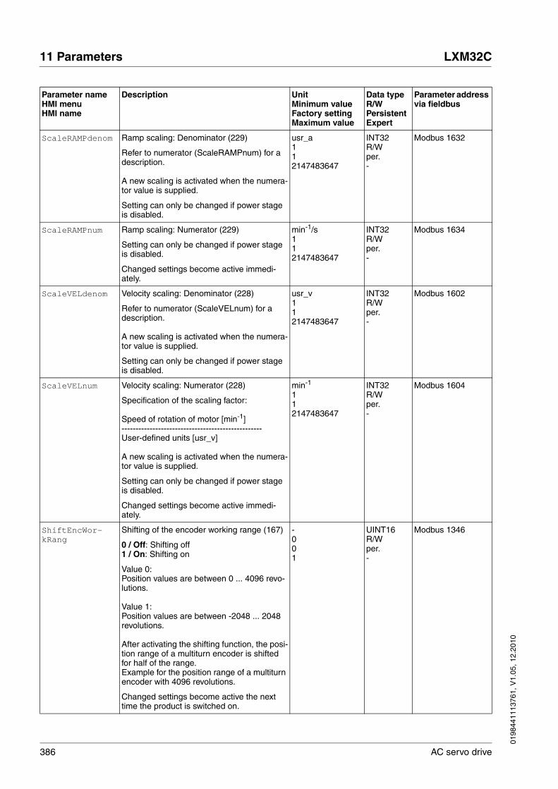
386 AC servo drive
11 Parameters LXM32C
0198
4411
1376
1, V
1.05
, 12.
2010
ScaleRAMPdenom Ramp scaling: Denominator (229)
Refer to numerator (ScaleRAMPnum) for a description.
A new scaling is activated when the numera-tor value is supplied.
Setting can only be changed if power stage is disabled.
usr_a112147483647
INT32R/Wper.-
Modbus 1632
ScaleRAMPnum Ramp scaling: Numerator (229)
Setting can only be changed if power stage is disabled.
Changed settings become active immedi-ately.
min-1/s112147483647
INT32R/Wper.-
Modbus 1634
ScaleVELdenom Velocity scaling: Denominator (228)
Refer to numerator (ScaleVELnum) for a description.
A new scaling is activated when the numera-tor value is supplied.
Setting can only be changed if power stage is disabled.
usr_v112147483647
INT32R/Wper.-
Modbus 1602
ScaleVELnum Velocity scaling: Numerator (228)
Specification of the scaling factor:
Speed of rotation of motor [min-1]--------------------------------------------------User-defined units [usr_v]
A new scaling is activated when the numera-tor value is supplied.
Setting can only be changed if power stage is disabled.
Changed settings become active immedi-ately.
min-1
112147483647
INT32R/Wper.-
Modbus 1604
ShiftEncWor-kRang
Shifting of the encoder working range (167)
0 / Off: Shifting off1 / On: Shifting on
Value 0:Position values are between 0 ... 4096 revo-lutions.
Value 1:Position values are between -2048 ... 2048 revolutions.
After activating the shifting function, the posi-tion range of a multiturn encoder is shifted for half of the range.Example for the position range of a multiturn encoder with 4096 revolutions.
Changed settings become active the next time the product is switched on.
-001
UINT16R/Wper.-
Modbus 1346
Parameter nameHMI menuHMI name
Description UnitMinimum valueFactory settingMaximum value
Data typeR/WPersistentExpert
Parameter address via fieldbus

0198
4411
1376
1, V
1.05
, 12.
2010
LXM32C 11 Parameters
AC servo drive 387
SimAbsolutePos
ConF → ACG-
qAbS
Simulation of absolute position at power cycling
0 / Simulation Off / oFF: Do not use the last mechanical position after power cycling1 / Simulation On / on: Use last mechani-cal position after power cycling
This parameter defines the way position val-ues are handled over a power cycle and allows for the simulation of an absolute posi-tion encoder using singleturn encoders.
If this function is activated, the device saves the relevant position data before a shutdown to restore the mechanical position the next time it is switched on.
In the case of singleturn encoders, the posi-tion can be restored if the motor shaft is not moved by more than 0.25 revolutions while the drive is off.
In the case of multiturn encoders, the per-missible shaft movement while the drive is off can be much greater, depending on the type of multiturn encoder.
For this function to work, the drive may only be shut down while the motor is at a stand-still and the motor shaft must not be moved outside of the permissible range (for exam-ple, use a brake).
Changed settings become active immedi-ately.
-001
UINT16R/Wper.-
Modbus 1350
Parameter nameHMI menuHMI name
Description UnitMinimum valueFactory settingMaximum value
Data typeR/WPersistentExpert
Parameter address via fieldbus

388 AC servo drive
11 Parameters LXM32C
0198
4411
1376
1, V
1.05
, 12.
2010

0198
4411
1376
1, V
1.05
, 12.
2010
LXM32C 12 Accessories and spare parts
AC servo drive 389
1212 Accessories and spare parts
12.1 Commissioning tools
12.2 Memory cards
12.3 Application nameplate
12.4 Adapter cable for encoder signals LXM05/LXM15 to LXM32
12.5 Cables for PTO and PTI
Description Order no.
Commissioning software Lexium CTcan be downloaded at: www.schneider-electric.com
-
PC connection kit, serial connection between drive and PC, USB-A to RJ45 TCSMCNAM3M002P
Multiloader, device for copying the parameter settings to a PC or to another drive VW3A8121
Modbus cable, 1 m, 2 x RJ45 VW3A8306R10
External graphic display terminal VW3A1101
Description Order no.
Memory card for copying parameter settings VW3M8705
25 memory cards for copying parameter settings VW3M8704
Description Order no.
Application name plate to be clipped onto the top of the drive, size 38.5 mm x 13 mm for label size 1.5 inches x 0.5 inches, 50 pieces
VW3M2501
Description Order no.
Encoder adapter cable Molex 10-pin (LXM05) to RJ45 10-pin (LXM32), 1 m VW3M8111R10
Encoder adapter cable D15-SUB (LXM15) to RJ45 10-pin (LXM32), 1 m VW3M8112R10
Description Order no.
Signal cable 2 x RJ45, PTO to PTI, 0.3 m VW3M8502R03
Signal cable 2 x RJ45, PTO to PTI, 1.5 m VW3M8502R15
Signal cable 1 x RJ45, other cable end open, for connecting PTI in the control cabinet, 3 m VW3M8223R30

390 AC servo drive
12 Accessories and spare parts LXM32C
0198
4411
1376
1, V
1.05
, 12.
2010
12.6 Motor cables
12.6.1 Motor cables 1.5 mm2
For BMH070, BMH100 (flange 70 mmand 100 mm).
12.6.2 Motor cables 2.5 mm2
For BMH140, (flange 140 mm).
Description Order no.
Motor cable 1.5 m, [(4 x 1.5 mm2) + (2 x 1 mm2)] shielded; motor end 8-pin circular connector M23, other cable end open
VW3M5101R15
Motor cable 3 m, [(4 x 1.5 mm2) + (2 x 1 mm2)] shielded; motor end 8-pin circular connector M23, other cable end open
VW3M5101R30
Motor cable 5 m, [(4 x 1.5 mm2) + (2 x 1 mm2)] shielded; motor end 8-pin circular connector M23, other cable end open
VW3M5101R50
Motor cable 10 m, [(4 x 1.5 mm2) + (2 x 1 mm2)] shielded; motor end 8-pin circular connector M23, other cable end open
VW3M5101R100
Motor cable 15 m, [(4 x 1.5 mm2) + (2 x 1 mm2)] shielded; motor end 8-pin circular connector M23, other cable end open
VW3M5101R150
Motor cable 20 m, [(4 x 1.5 mm2) + (2 x 1 mm2)] shielded; motor end 8-pin circular connector M23, other cable end open
VW3M5101R200
Motor cable 25 m, [(4 x 1.5 mm2) + (2 x 1 mm2)] shielded; motor end 8-pin circular connector M23, other cable end open
VW3M5101R250
Motor cable 50 m, [(4 x 1.5 mm2) + (2 x 1 mm2)] shielded; motor end 8-pin circular connector M23, other cable end open
VW3M5101R500
Motor cable 75 m, [(4 x 1.5 mm2) + (2 x 1 mm2)] shielded; motor end 8-pin circular connector M23, other cable end open
VW3M5101R750
Motor cable 25 m, [(4 x 1.5 mm2) + (2 x 1 mm2)] shielded; both cable ends open VW3M5301R250
Motor cable 50 m, [(4 x 1.5 mm2) + (2 x 1 mm2)] shielded; both cable ends open VW3M5301R500
Motor cable 100 m, [(4 x 1.5 mm2) + (2 x 1 mm2)] shielded; both cable ends open VW3M5301R1000
Description Order no.
Motor cable 1.5 m, [(4 x 2.5 mm2) + (2 x 1 mm2)] shielded; motor end 8-pin circular connector M23, other cable end open
VW3M5102R15
Motor cable 3 m, [(4 x 2.5 mm2) + (2 x 1 mm2)] shielded; motor end 8-pin circular connector M23, other cable end open
VW3M5102R30
Motor cable 5 m, [(4 x 2.5 mm2) + (2 x 1 mm2)] shielded; motor end 8-pin circular connector M23, other cable end open
VW3M5102R50
Motor cable 10 m, [(4 x 2.5 mm2) + (2 x 1 mm2)] shielded; motor end 8-pin circular connector M23, other cable end open
VW3M5102R100
Motor cable 15 m, [(4 x 2.5 mm2) + (2 x 1 mm2)] shielded; motor end 8-pin circular connector M23, other cable end open
VW3M5102R150
Motor cable 20 m, [(4 x 2.5 mm2) + (2 x 1 mm2)] shielded; motor end 8-pin circular connector M23, other cable end open
VW3M5102R200
Motor cable 25 m, [(4 x 2.5 mm2) + (2 x 1 mm2)] shielded; motor end 8-pin circular connector M23, other cable end open
VW3M5102R250
Motor cable 50 m, [(4 x 2.5 mm2) + (2 x 1 mm2)] shielded; motor end 8-pin circular connector M23, other cable end open
VW3M5102R500
Motor cable 75 m, [(4 x 2.5 mm2) + (2 x 1 mm2)] shielded; motor end 8-pin circular connector M23, other cable end open
VW3M5102R750

0198
4411
1376
1, V
1.05
, 12.
2010
LXM32C 12 Accessories and spare parts
AC servo drive 391
12.6.3 Motor cables 4 mm2
For BMH205, (flange 205 mm).
12.7 Encoder cables
Suitable for BMH motors:
Motor cable 25 m, [(4 x 2.5 mm2) + (2 x 1 mm2)] shielded; both cable ends open VW3M5302R250
Motor cable 50 m, [(4 x 2.5 mm2) + (2 x 1 mm2)] shielded; both cable ends open VW3M5302R500
Motor cable 100 m, [(4 x 2.5 mm2) + (2 x 1 mm2)] shielded; both cable ends open VW3M5302R1000
Description Order no.
Description Order no.
Motor cable 3 m, [(4 x 4 mm2) + (2 x 1 mm2)] shielded; motor end 8-pin circular connector M40, other cable end open
VW3M5103R30
Motor cable 5 m, [(4 x 4 mm2) + (2 x 1 mm2)] shielded; motor end 8-pin circular connector M40, other cable end open
VW3M5103R50
Motor cable 10 m, [(4 x 4 mm2) + (2 x 1 mm2)] shielded; motor end 8-pin circular connector M40, other cable end open
VW3M5103R100
Motor cable 15 m, [(4 x 4 mm2) + (2 x 1 mm2)] shielded; motor end 8-pin circular connector M40, other cable end open
VW3M5103R150
Motor cable 20 m, [(4 x 4 mm2) + (2 x 1 mm2)] shielded; motor end 8-pin circular connector M40, other cable end open
VW3M5103R200
Motor cable 25 m, [(4 x 4 mm2) + (2 x 1 mm2)] shielded; motor end 8-pin circular connector M40, other cable end open
VW3M5103R250
Motor cable 50 m, [(4 x 4 mm2) + (2 x 1 mm2)] shielded; motor end 8-pin circular connector M40, other cable end open
VW3M5103R500
Motor cable 75 m, [(4 x 4 mm2) + (2 x 1 mm2)] shielded; motor end 8-pin circular connector M40, other cable end open
VW3M5103R750
Motor cable 25 m, [(4 x 4 mm2) + (2 x 1 mm2)] shielded; both cable ends open VW3M5303R250
Motor cable 50 m, [(4 x 4 mm2) + (2 x 1 mm2)] shielded; both cable ends open VW3M5303R500
Motor cable 100 m, [(4 x 4 mm2) + (2 x 1 mm2)] shielded; both cable ends open VW3M5303R1000
Description Order no.
Encoder cable 1.5 m, [3 x (2 x 0.14 mm2) + (2 x 0.34 mm2)] shielded; motor end 12-pin circular connector M23, device end 10-pin connector RJ45
VW3M8102R15
Encoder cable 3 m, [3 x (2 x 0.14 mm2) + (2 x 0.34 mm2)] shielded; motor end 12-pin circular connector M23, device end 10-pin connector RJ45
VW3M8102R30
Encoder cable 5 m, [3 x (2 x 0.14 mm2) + (2 x 0.34 mm2)] shielded; motor end 12-pin circular connector M23, device end 10-pin connector RJ45
VW3M8102R50
Encoder cable 10 m, [3 x (2 x 0.14 mm2) + (2 x 0.34 mm2)] shielded; motor end 12-pin circular connector M23, device end 10-pin connector RJ45
VW3M8102R100
Encoder cable 15 m, [3 x (2 x 0.14 mm2) + (2 x 0.34 mm2)] shielded; motor end 12-pin circular connector M23, device end 10-pin connector RJ45
VW3M8102R150
Encoder cable 20 m, [3 x (2 x 0.14 mm2) + (2 x 0.34 mm2)] shielded; motor end 12-pin circular connector M23, device end 10-pin connector RJ45
VW3M8102R200
Encoder cable 25 m, [3 x (2 x 0.14 mm2) + (2 x 0.34 mm2)] shielded; motor end 12-pin circular connector M23, device end 10-pin connector RJ45
VW3M8102R250
Encoder cable 50 m, [3 x (2 x 0.14 mm2) + (2 x 0.34 mm2)] shielded; motor end 12-pin circular connector M23, device end 10-pin connector RJ45
VW3M8102R500
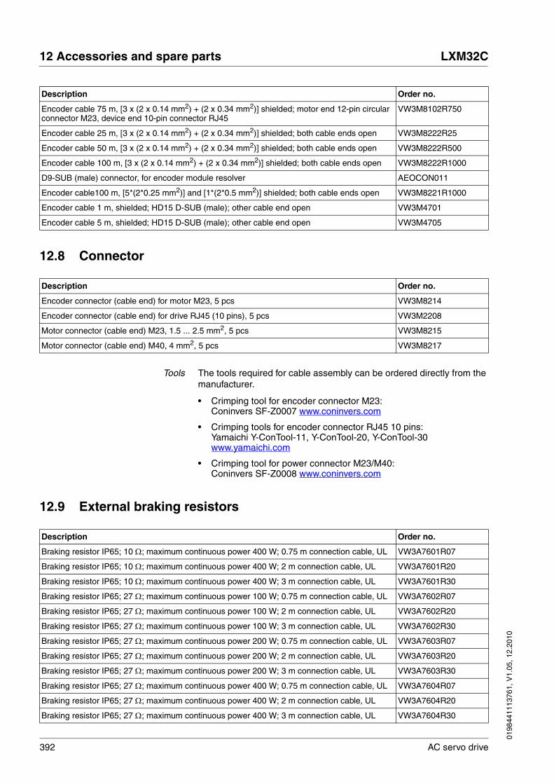
392 AC servo drive
12 Accessories and spare parts LXM32C
0198
4411
1376
1, V
1.05
, 12.
2010
12.8 Connector
Tools The tools required for cable assembly can be ordered directly from the manufacturer.
• Crimping tool for encoder connector M23:Coninvers SF-Z0007 www.coninvers.com
• Crimping tools for encoder connector RJ45 10 pins:Yamaichi Y-ConTool-11, Y-ConTool-20, Y-ConTool-30www.yamaichi.com
• Crimping tool for power connector M23/M40:Coninvers SF-Z0008 www.coninvers.com
12.9 External braking resistors
Encoder cable 75 m, [3 x (2 x 0.14 mm2) + (2 x 0.34 mm2)] shielded; motor end 12-pin circular connector M23, device end 10-pin connector RJ45
VW3M8102R750
Encoder cable 25 m, [3 x (2 x 0.14 mm2) + (2 x 0.34 mm2)] shielded; both cable ends open VW3M8222R25
Encoder cable 50 m, [3 x (2 x 0.14 mm2) + (2 x 0.34 mm2)] shielded; both cable ends open VW3M8222R500
Encoder cable 100 m, [3 x (2 x 0.14 mm2) + (2 x 0.34 mm2)] shielded; both cable ends open VW3M8222R1000
D9-SUB (male) connector, for encoder module resolver AEOCON011
Encoder cable100 m, [5*(2*0.25 mm2)] and [1*(2*0.5 mm2)] shielded; both cable ends open VW3M8221R1000
Encoder cable 1 m, shielded; HD15 D-SUB (male); other cable end open VW3M4701
Encoder cable 5 m, shielded; HD15 D-SUB (male); other cable end open VW3M4705
Description Order no.
Description Order no.
Encoder connector (cable end) for motor M23, 5 pcs VW3M8214
Encoder connector (cable end) for drive RJ45 (10 pins), 5 pcs VW3M2208
Motor connector (cable end) M23, 1.5 ... 2.5 mm2, 5 pcs VW3M8215
Motor connector (cable end) M40, 4 mm2, 5 pcs VW3M8217
Description Order no.
Braking resistor IP65; 10 Ω; maximum continuous power 400 W; 0.75 m connection cable, UL VW3A7601R07
Braking resistor IP65; 10 Ω; maximum continuous power 400 W; 2 m connection cable, UL VW3A7601R20
Braking resistor IP65; 10 Ω; maximum continuous power 400 W; 3 m connection cable, UL VW3A7601R30
Braking resistor IP65; 27 Ω; maximum continuous power 100 W; 0.75 m connection cable, UL VW3A7602R07
Braking resistor IP65; 27 Ω; maximum continuous power 100 W; 2 m connection cable, UL VW3A7602R20
Braking resistor IP65; 27 Ω; maximum continuous power 100 W; 3 m connection cable, UL VW3A7602R30
Braking resistor IP65; 27 Ω; maximum continuous power 200 W; 0.75 m connection cable, UL VW3A7603R07
Braking resistor IP65; 27 Ω; maximum continuous power 200 W; 2 m connection cable, UL VW3A7603R20
Braking resistor IP65; 27 Ω; maximum continuous power 200 W; 3 m connection cable, UL VW3A7603R30
Braking resistor IP65; 27 Ω; maximum continuous power 400 W; 0.75 m connection cable, UL VW3A7604R07
Braking resistor IP65; 27 Ω; maximum continuous power 400 W; 2 m connection cable, UL VW3A7604R20
Braking resistor IP65; 27 Ω; maximum continuous power 400 W; 3 m connection cable, UL VW3A7604R30

0198
4411
1376
1, V
1.05
, 12.
2010
LXM32C 12 Accessories and spare parts
AC servo drive 393
12.10 DC bus accessories
12.11 Mains reactors
12.12 External mains filters
Braking resistor IP65; 72 Ω; maximum continuous power 100 W; 0.75 m connection cable, UL VW3A7605R07
Braking resistor IP65; 72 Ω; maximum continuous power 100 W; 2 m connection cable, UL VW3A7605R20
Braking resistor IP65; 72 Ω; maximum continuous power 100 W; 3 m connection cable, UL VW3A7605R30
Braking resistor IP65; 72 Ω; maximum continuous power 200 W; 0.75 m connection cable, UL VW3A7606R07
Braking resistor IP65; 72 Ω; maximum continuous power 200 W; 2 m connection cable, UL VW3A7606R20
Braking resistor IP65; 72 Ω; maximum continuous power 200 W; 3 m connection cable, UL VW3A7606R30
Braking resistor IP65; 72 Ω; maximum continuous power 400 W; 0.75 m connection cable VW3A7607R07
Braking resistor IP65; 72 Ω; maximum continuous power 400 W; 2 m connection cable VW3A7607R20
Braking resistor IP65; 72 Ω; maximum continuous power 400 W; 3 m connection cable VW3A7607R30
Braking resistor IP65; 100 Ω; maximum continuous power 100 W; 0.75 m connection cable VW3A7608R07
Braking resistor IP65; 100 Ω; maximum continuous power 100 W; 2 m connection cable VW3A7608R20
Braking resistor IP65; 100 Ω; maximum continuous power 100 W; 3 m connection cable VW3A7608R30
Braking resistor IP20; 15 Ω; maximum continuous power 2500 W; connection terminals, UL VW3A7704
Braking resistor IP20; 10 Ω; maximum continuous power 2500 W; connection terminals, UL VW3A7705
Description Order no.
Description Order no.
LXM ATV DC bus connection cable, pre-assembled, 0.1 m, 5 pieces VW3M7101R01
DC bus connector kit, connector housing and contacts, 10 pieces VW3M2207
Description Order no.
Mains reactor 1~; 50-60Hz; 7A; 5mH; IP00 VZ1L007UM50
Mains reactor 1~; 50-60Hz; 18A; 2mH; IP00 VZ1L018UM20
Mains reactor 3~; 50-60Hz; 16A; 2mH; IP00 VW3A4553
Mains reactor 3~; 50-60Hz; 30A; 1mH; IP00 VW3A4554
Description Order no.
Mains filter 1~; 9 A; 115/230 VAC for LXM32 VW3A4420
Mains filter 1~; 16 A; 115/230 VAC for LXM32 VW3A4421
Mains filter 3~; 15A; 208/400/480VAC for LXM32 VW3A4422
Mains filter 3~; 25A; 208/400/480VAC for LXM32 VW3A4423
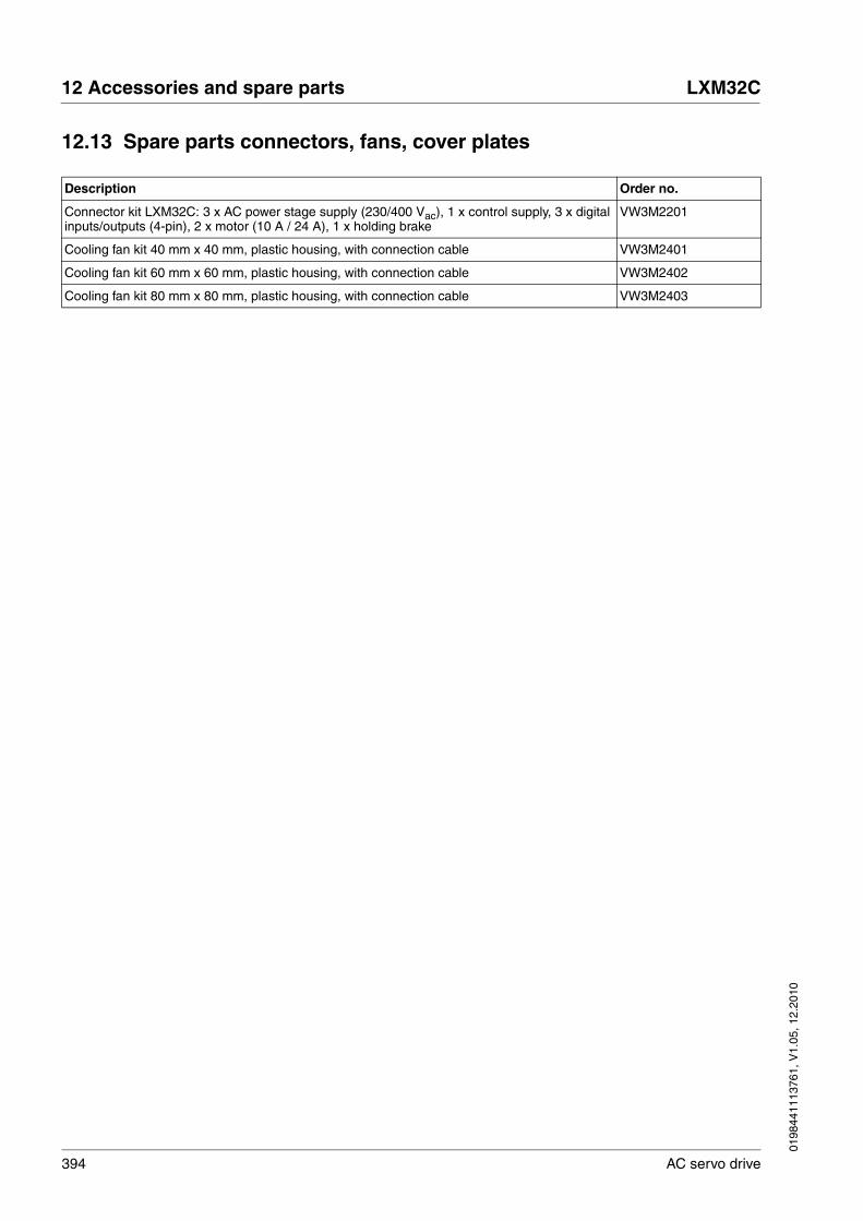
394 AC servo drive
12 Accessories and spare parts LXM32C
0198
4411
1376
1, V
1.05
, 12.
2010
12.13 Spare parts connectors, fans, cover plates
Description Order no.
Connector kit LXM32C: 3 x AC power stage supply (230/400 Vac), 1 x control supply, 3 x digital inputs/outputs (4-pin), 2 x motor (10 A / 24 A), 1 x holding brake
VW3M2201
Cooling fan kit 40 mm x 40 mm, plastic housing, with connection cable VW3M2401
Cooling fan kit 60 mm x 60 mm, plastic housing, with connection cable VW3M2402
Cooling fan kit 80 mm x 80 mm, plastic housing, with connection cable VW3M2403
0198
4411
1376
1, V
1.05
, 12.
2010
LXM32C 13 Service, maintenance and disposal
AC servo drive 395
1313 Service, maintenance and disposal
The product may only be repaired by a Schneider Electric customer service center. No warranty or liability is accepted for repairs made by unauthorized persons.
13.1 Service address
If you cannot resolve an error yourself please contact your sales office. Have the following details available:
• Nameplate (type, identification number, serial number, DOM, ...)
• Type of error (with LED flash code or error number)
• Previous and concomitant circumstances
• Your own assumptions concerning the cause of the error
Also include this information if you return the product for inspection or re-pair.
If you have any questions please contact your sales office. Your sales office staff will be happy to give you the name of a customer service office in your area.
http://www.schneider-electric.com
13.2 Maintenance
Check the product for pollution or damage at regular intervals.
13.2.1 Lifetime STO safety function
The STO safety function is designed for a lifetime of 20 years. After this period, the data of the safety function are no longer valid. The expiry date is determined by adding 20 years to the DOM shown on the name-plate of the product.
� This date must be included in the maintenance plan of the system.
Do not use the safety function after this date.
Example The DOM on the nameplate of the product is shown in the format DD.MM.YY, for example 31.12.08. (31 December 2008). This means: Do not use the safety function after December 31, 2028.

396 AC servo drive
13 Service, maintenance and disposal LXM32C
0198
4411
1376
1, V
1.05
, 12.
2010
13.3 Replacing devices
Prepare a list with the parameters required for the functions used.
Observe the following procedure when replacing devices.
� Save all parameter settings. To do so, use a memory card, see chapter 7.8 "Memory Card", page 185, or save the data to a PC using the commissioning software, see chapter 7.5 "Commissioning software", page 146.
� Switch off all supply voltages. Verify that no voltages are present (safety instructions).
� Label all connections and remove all connection cables (unlock connector locks).
� Uninstall the product.
� Note the identification number and the serial number shown on the product nameplate for later identification.
� Install the new product as per chapter 6 "Installation".
� If the product to be installed has previously been used in a different system or application, you must restore the factory settings before commissioning the product.
� Commission the product as per chapter 7 "Commissioning".
@ WARNINGUNINTENDED BEHAVIOR
The behavior of the drive system is governed by numerous stored data or settings. Unsuitable settings or data may trigger unexpected movements or responses to signals and disable monitoring functions.
• Do NOT operate the drive system with unknown settings or data.
• Verify that the stored data and settings are correct.
• When commissioning, carefully run tests for all operating states and potential error situations.
• Verify the functions after replacing the product and also after making changes to the settings or data.
• Only start the system if there are no persons or obstructions in the hazardous area.
Failure to follow these instructions can result in death, serious injury or equipment damage.

0198
4411
1376
1, V
1.05
, 12.
2010
LXM32C 13 Service, maintenance and disposal
AC servo drive 397
13.4 Changing the motor
� Switch off all supply voltages. Verify that no voltages are present (safety instructions).
� Label all connections and uninstall the product.
� Note the identification number and the serial number shown on the product nameplate for later identification.
� Install the new product as per chapter 6 "Installation".
If the connected motor is replaced by another motor, the motor data set is read again. If the device detects a different motor type, the controller parameters are recalculated and the HMI displays MOT. See chapter 10.3.3 "Acknowledging a motor change", page 303 for additional infor-mation.
If the motor is replaced, the encoder parameters must also be re-ad-justed, see chapter 7.6.9 "Setting parameters for encoder", page 164.
Changing the motor typetemporarily
� If you want to operate the new motor type only temporarily via the device, press ESC at the HMI.
� The newly calculated controller parameters are not saved to the EEPROM. This way, you can resume operation with the original motor using the saved controller parameters.
Changing the motor typepermanently
� If you want to operate the new motor type permanently via this device, press the navigation button at the HMI.
� The newly calculated controller parameters are saved to the EEP-ROM.
See also chapter 10.3.3 "Acknowledging a motor change", page 303.
@ WARNINGUNEXPECTED MOVEMENT
Drive systems may perform unexpected movements because of in-correct connection or other errors.
• Operate the device with approved motors only. Even if motors are similar, different adjustment of the encoder system may be a source of hazards.
• Even if the connectors for power connection and encoder match mechanically, this does NOT imply that they may be used.
Failure to follow these instructions can result in death, serious injury or equipment damage.
398 AC servo drive
13 Service, maintenance and disposal LXM32C
0198
4411
1376
1, V
1.05
, 12.
2010
13.5 Shipping, storage, disposal
Note the ambient conditions on page 21.
Shipping The product must be protected against shocks during transportation. If possible, use the original packaging for shipping.
Storage The product may only be stored in spaces where the specified permis-sible ambient conditions are met.Protect the product from dust and dirt.
Disposal The product consists of various materials that can be recycled. Dispose of the product in accordance with local regulations.

0198
4411
1376
1, V
1.05
, 12.
2010
LXM32C 14 Glossary
AC servo drive 399
1414 Glossary
14.1 Units and conversion tables
The value in the specified unit (left column) is calculated for the desired unit (top row) with the formula (in the field).
Example: conversion of 5 meters [m] to yards [yd]5 m / 0.9144 = 5.468 yd
14.1.1 Length
14.1.2 Mass
14.1.3 Force
14.1.4 Power
in ft yd m cm mm
in - / 12 / 36 * 0.0254 * 2.54 * 25.4
ft * 12 - / 3 * 0.30479 * 30.479 * 304.79
yd * 36 * 3 - * 0.9144 * 91.44 * 914.4
m / 0.0254 / 0.30479 / 0.9144 - * 100 * 1000
cm / 2.54 / 30.479 / 91.44 / 100 - * 10
mm / 25.4 / 304.79 / 914.4 / 1000 / 10 -
lb oz slug kg g
lb - * 16 * 0.03108095 * 0.4535924 * 453.5924
oz / 16 - * 1.942559*10-3 * 0.02834952 * 28.34952
slug / 0.03108095 / 1.942559*10-3 - * 14.5939 * 14593.9
kg / 0.45359237 / 0.02834952 / 14.5939 - * 1000
g / 453.59237 / 28.34952 / 14593.9 / 1000 -
lb oz p dyne N
lb - * 16 * 453.55358 * 444822.2 * 4.448222
oz / 16 - * 28.349524 * 27801 * 0.27801
p / 453.55358 / 28.349524 - * 980.7 * 9.807*10-3
dyne / 444822.2 / 27801 / 980.7 - / 100*103
N / 4.448222 / 0.27801 / 9.807*10-3 * 100*103 -
HP W
HP - * 746
W / 746 -
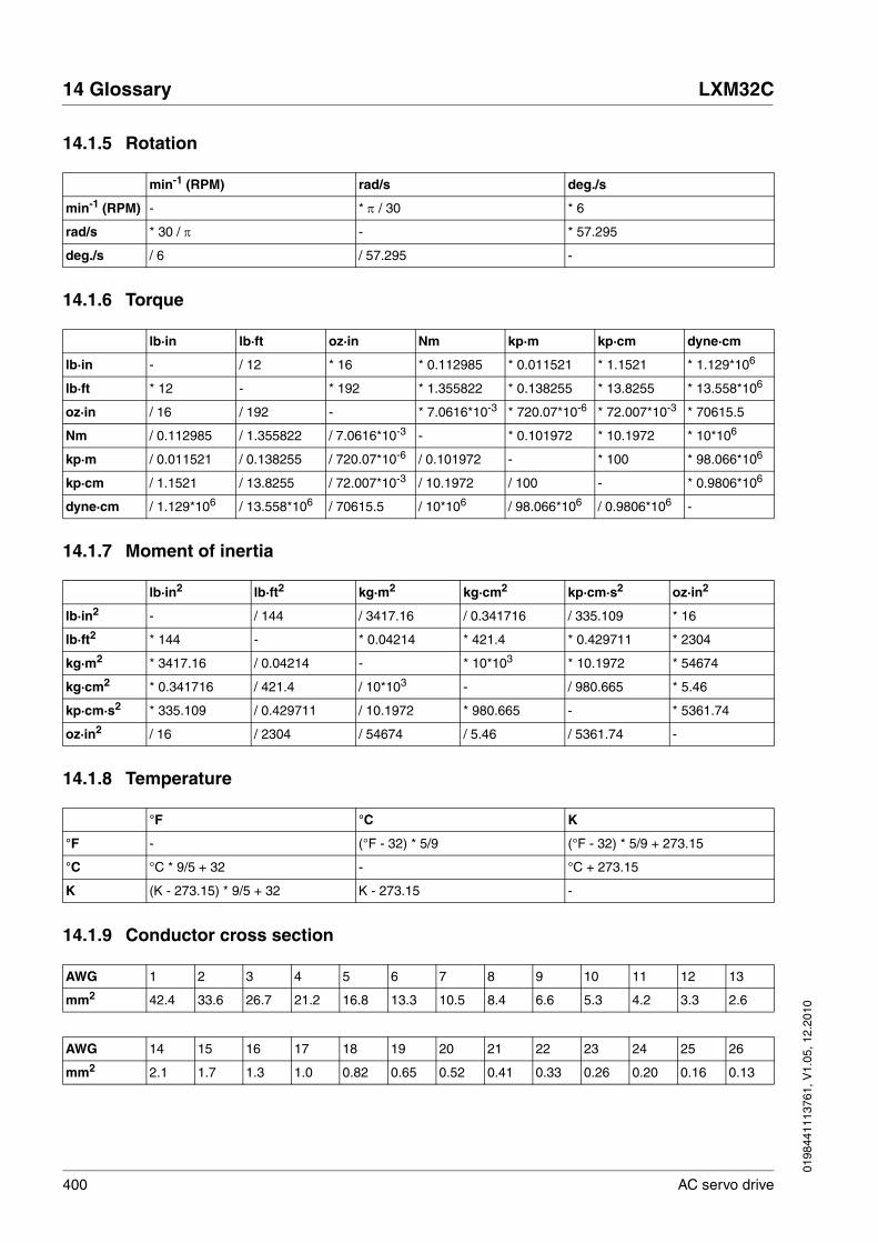
400 AC servo drive
14 Glossary LXM32C
0198
4411
1376
1, V
1.05
, 12.
2010
14.1.5 Rotation
14.1.6 Torque
14.1.7 Moment of inertia
14.1.8 Temperature
14.1.9 Conductor cross section
min-1 (RPM) rad/s deg./s
min-1 (RPM) - * π / 30 * 6
rad/s * 30 / π - * 57.295
deg./s / 6 / 57.295 -
lb·in lb·ft oz·in Nm kp·m kp·cm dyne·cm
lb·in - / 12 * 16 * 0.112985 * 0.011521 * 1.1521 * 1.129*106
lb·ft * 12 - * 192 * 1.355822 * 0.138255 * 13.8255 * 13.558*106
oz·in / 16 / 192 - * 7.0616*10-3 * 720.07*10-6 * 72.007*10-3 * 70615.5
Nm / 0.112985 / 1.355822 / 7.0616*10-3 - * 0.101972 * 10.1972 * 10*106
kp·m / 0.011521 / 0.138255 / 720.07*10-6 / 0.101972 - * 100 * 98.066*106
kp·cm / 1.1521 / 13.8255 / 72.007*10-3 / 10.1972 / 100 - * 0.9806*106
dyne·cm / 1.129*106 / 13.558*106 / 70615.5 / 10*106 / 98.066*106 / 0.9806*106 -
lb·in2 lb·ft2 kg·m2 kg·cm2 kp·cm·s2 oz·in2
lb·in2 - / 144 / 3417.16 / 0.341716 / 335.109 * 16
lb·ft2 * 144 - * 0.04214 * 421.4 * 0.429711 * 2304
kg·m2 * 3417.16 / 0.04214 - * 10*103 * 10.1972 * 54674
kg·cm2 * 0.341716 / 421.4 / 10*103 - / 980.665 * 5.46
kp·cm·s2 * 335.109 / 0.429711 / 10.1972 * 980.665 - * 5361.74
oz·in2 / 16 / 2304 / 54674 / 5.46 / 5361.74 -
°F °C K
°F - (°F - 32) * 5/9 (°F - 32) * 5/9 + 273.15
°C °C * 9/5 + 32 - °C + 273.15
K (K - 273.15) * 9/5 + 32 K - 273.15 -
AWG 1 2 3 4 5 6 7 8 9 10 11 12 13
mm2 42.4 33.6 26.7 21.2 16.8 13.3 10.5 8.4 6.6 5.3 4.2 3.3 2.6
AWG 14 15 16 17 18 19 20 21 22 23 24 25 26
mm2 2.1 1.7 1.3 1.0 0.82 0.65 0.52 0.41 0.33 0.26 0.20 0.16 0.13
0198
4411
1376
1, V
1.05
, 12.
2010
LXM32C 14 Glossary
AC servo drive 401
14.2 Terms and Abbreviations
See chapter 2.7 "Standards and terminology" for information on the per-tinent standards on which many terms are based. Some terms and ab-breviations may have specific meanings with regard to the standards.
AC Alternating current
Actual position Current position of moving components in the drive system.
CCW Counter Clockwise.
CW Clockwise.
DC Direct current
DC bus Circuit that supplies the power stage with energy (direct voltage).
DOM Date of manufacturing: The nameplate of the product shows the date of manufacture in the format DD.MM.YY or in the format DD.MM.YYYY. Ex-ample:31.12.09 corresponds to December 31, 2009 31.12.2009 corresponds to December 31, 2009
Degree of protection The degree of protection is a standardized specification for electrical equipment that describes the protection against the ingress of foreign objects and water (for example: IP 20).
Direction of rotation Rotation of the motor shaft in a positive or negative direction of rotation. Positive direction of rotation is when the motor shaft rotates clockwise as you look at the end of the protruding motor shaft.
Drive system System consisting of controller, power stage and motor.
EMC Electromagnetic compatibility
Electronic gear Calculation of a new output velocity for the motor movement based on the input velocity and the values of an adjustable gear ratio; calculated by the drive system.
Encoder Sensor for detection of the angular position of a rotating component. In-stalled in a motor, the encoder shows the angular position of the rotor.
Error Discrepancy between a computed, observed or measured value or con-dition and the specified or theoretically correct value or condition.
Error class Classification of errors into groups. The different error classes allow for specific responses to errors, for example by severity.
Factory setting Factory settings when the product is shipped
Fatal error In the case of fatal error, the product is no longer able to control the mo-tor so that the power stage must be immediately disabled.
Fault Fault is a state that can be caused by an error. Further information can be found in the pertinent standards such as IEC 61800-7, ODVA Com-mon Industrial Protocol (CIP).
Fault reset A function used to restore the drive to an operational state after a de-tected error is cleared by removing the cause of the error so that the er-ror is no longer active.
Holding brake The holding brake in the motor has the task of holding the current motor position when the power stage is disabled, even if external forces act (for example, in the case of a vertical axis). The holding brake is not a safety function.

402 AC servo drive
14 Glossary LXM32C
0198
4411
1376
1, V
1.05
, 12.
2010
The signals of the holding brake meet the PELV requirements.
I/O Inputs/outputs
I2t monitoring Anticipatory temperature monitoring. The expected temperature rise of components is calculated in advance on the basis of the motor current. If a limit value is exceeded, the drive reduces the motor current.
IT mains Mains in which all active components are isolated from ground or are grounded by a high impedance. IT: isolé terre (French), isolated ground.Opposite: Grounded mains, see TT/TN mains
Inc Increments
Index pulse Signal of an encoder to reference the rotor position in the motor. The en-coder returns one index pulse per revolution.
Internal units Resolution of the power stage at which the motor can be positioned. In-ternal units are specified in increments.
Limit switch Switches that signal overtravel of the permissible range of travel.
PC Personal Computer
PELV Protective Extra Low Voltage, low voltage with isolation. For more infor-mation: IEC 60364-4-41
PLC Programmable logic controller
Parameter Device data and values that can be read and set (to a certain extent) by the user.
Persistent Indicates whether the value of the parameter remains in the memory af-ter the device is switched off.
Power stage The power stage controls the motor. The power stage generates current for controlling the motor on the basis of the positioning signals from the controller.
Pulse/direction signals Digital signals with variable pulse frequencies which signal changes in position and direction of movement via separate signal wires.
Quick Stop Function which can be used for fast deceleration of the motor via a com-mand or in the event of an error.
RCD RCD residual current device.
rms "Root Mean Square" value of a voltage (Vrms) or a current (Arms)
RS485 Fieldbus interface as per EIA-485 which enables serial data transmis-sion with multiple devices.
Scaling factor This factor is the ratio between an internal unit and a user-defined unit.
TT mains, TN mains Grounded mains, differ in terms of the ground connection (PE conductor connection). Opposite: Ungrounded mains, see IT mains.
User-defined unit Unit whose reference to motor movement can be determined by the user via parameters.
Warning If the term is used outside the context of safety instructions, a warning alerts to a potential problem that was detected by a monitoring function. A warning does not cause a transition of the operating state.

0198
4411
1376
1, V
1.05
, 12.
2010
LXM32C 15 Index
AC servo drive 403
1515 Index
Numerics24V controller supply voltage 118400/480V 3-phase devices UL 51
AA/B
Wiring diagram 117A/B 5V
Wiring diagram 116Abbreviations 401Access channels 191Accessories 49
External braking resistor, data 47Mains reactor 50, 67
Accessories and spare parts 389Ambient conditions 21
Connection 22Installation site 22
Analog inputsCable specifications 121Connection 121, 122
Analog inputs, testing 154Analog module
Analog input 154Approved motors 26Assembling cables
Motor phases 98Autotuning 170Autotuning, enhanced settings 173
BBefore you begin
Safety information 15Braking resistor 44
External 47Mounting 89Rating 70Selection 72
CCable installation - EMC requirements 59Cable specifications
Analog inputs 121Digital signals 123External braking resistor 104Graphic display terminal 125Motor connection 96Motor encoder 111

404 AC servo drive
15 Index LXM32C
0198
4411
1376
1, V
1.05
, 12.
2010
PC 125Protected cable installation 79PTI 115Pulse Train In 115
Cables 62Category 0 stop 77Category 1 stop 77Central grounding point 94Certifications 51Changing the motor 397Character set
HMI 133Commissioning 129
Analog inputs, testing 154Autotuning 170Controller structure 175Default settings and optimization 182Digital inputs and outputs 156Direction of movement, test 162Enhanced settings for autotuning 173Holding brake, checking 161optimizing controller 175Parameters for braking resistor 168Safety function STO, test 158Setting basic parameters 150setting parameters for encoder 164steps 147Velocity controller optimization 177
Commissioning software 146Online help 146Setting reference value signal 176Step function 176
Components and interfaces 12Connection
Ambient conditions 22Analog inputs 121Controller supply voltage 24V 118DC bus 102Digital inputs/outputs 123Encoder simulation 113ESIM 113External braking resistor 103Grounding screw 94Holding brake 101Mains supply, single-phase device 109Mains supply, three-phase device 110Motor encoder 111Motor phases 95PC 125Power stage supply voltage 106Power stage supply voltage single-phase device 109Power stage supply voltage three-phase device 110PTO 113Pulse Train Out 113Safety function STO 118STO 118
Connection assignment 24V

0198
4411
1376
1, V
1.05
, 12.
2010
LXM32C 15 Index
AC servo drive 405
A/B 117CW/CCW 117PTI 117Pulse Train In 117PULSE/DIR 117
Connection assignment 5VA/B 116CW/CCW 116PTI 116Pulse Train In 116PULSE/DIR 116
Connection overview 93Control cabinet 87Control cabinet design - EMC requirements 58Controller
optimizing 175Structure 175Values 176
Controller supply voltageConnection 120Permissible terminal current 119Rating 119
Controller supply voltage 24VDC 34Controller supply voltage connection 118Current controller
Function 175, 245CW/CCW 42
Wiring diagram 117CW/CCW 5V
Wiring diagram 116
DDC bus
Connection 102DC bus parallel connection 66Declaration of conformity 52Definition
STO 77Degree of protection 22Determining controller parameter values
Controller parameter values for rigid mechanical systems 179Device
Mounting 87, 88Device overview 11Diagnostics 297Diagram
A/B signals 40CW/CCW signals 42P/D signals 41
Digital inputs and outputsDisplay and modify 156
Digital inputs/outputsConnection 125
Direction of movement, test 162Direction of rotation ->Direction of movement 162Disposal 395, 398

406 AC servo drive
15 Index LXM32C
0198
4411
1376
1, V
1.05
, 12.
2010
EElectrical installation 91Electronic Gear 206EMC 58
Cable installation 59Control cabinet design 58Improvement 60Motor cable and encoder cable 60Power supply 59Shielded cables 59
Encoder (motor) connectionMotor encoderConnection 112
Encoder cableEMC requirements 60
Encoder simulationConnection 113
EPLAN Macros 9Equipotential bonding conductors 62Error class 194, 297Error response 194
Meaning 194, 297ESIM
Connection 113Examples 293External braking resistor
Cable specifications 104Connection 103, 105Mounting 90
External braking resistors 47External main filter
Mounting 89External mains filter 49
Mounting 89
FFault Reset 195First power up
Preparation 148Frequency power stage 26Function
Signals A/B 40Signals CW/CCW 42Signals P/D 41
Functional safety 19, 43, 55Further reading 10Fuses UL 51
GGlossary 399Grounding screw 94
HHazard categories 16HMI
Character set 133Holding brake 159
0198
4411
1376
1, V
1.05
, 12.
2010
LXM32C 15 Index
AC servo drive 407
Connection 101Holding brake, checking 161
IImprovement of EMC 60Installation
electrical 91mechanical 86
Installation siteAmbient conditions 22
Intended use 15Internal mains filter 48Introduction 11IP degree of protection 22IT mains, operation in 65
JJog 200
LLimit values
Setting 150Limits
Analog inputs 122
MMacros EPLAN 9Mains filter 68
External 49internal 48
Mains filter, external 49Mains reactor 50, 67
Mounting 89Mains supply
Connection single-phase device 109Connection three-phase device 110
Mains supply, connection 107Maintenance 395Manuals
Source 9Mechanical installation 86Mechanical system, design for control system 178Monitoring
Braking resistor 72Motor phases 99
Monitoring functions 83Motor cable
Connection 100EMC requirements 60
Motor data recordAutomatic reading 148
Motor encoderConnection 111Encoder type 111Function 111
Mounting

408 AC servo drive
15 Index LXM32C
0198
4411
1376
1, V
1.05
, 12.
2010
External braking resistor 90External mains filter 89Mains reactor 89Mechanical 87
Mounting distances 87
OOperating mode
Electronic Gear 206Jog 200Profile Torque 215Profile Velocity 221
Operating mode, changing 198Operating mode, starting 198Operating modes 198
Changing 198Starting 198
Operating state 149Operating state, changing the 197Operating states 193
Indicating operating states 196Operating state, changing the 197State diagram 193
Operating states, indication 196Operation 189Optimization of default settings 182Overview 131
Connections 93Procedure for electrical installation 92
Overvoltage categoryUL 51
PP/D
Wiring diagram 117Parallel connection DC bus 66Parameter
representation 321Parameters 321Parameters for braking resistor 168PC
Connection 125Pollution degree 22Position controller
Function 176, 245optimizing 183
Power stage frequency 26Power stage supply voltage
Connection 107Connection single-phase device 109Connection three-phase device 110
Power supply - EMC requirements 59Profile Torque 215Profile Velocity 221Protected cable installation 79PT_in 5V

0198
4411
1376
1, V
1.05
, 12.
2010
LXM32C 15 Index
AC servo drive 409
Wiring diagramPulse Train 5V
Wiring diagram 116PTI
Wiring diagramPulse Train
Wiring diagram 117PTO
Connection 113Pulse Train In
24 V connection 1175 V connection 116Connection assignment 24V 117Connection assignment 5V 116
Pulse Train OutConnection 113
Pulse/Direction 41Pulse/direction P/D 5V
Wiring diagram 116PWM frequency 26
QQualification of personnel 15
RRating
Controller supply voltage 119Rating information
Braking resistor 73Rating of braking resistor 70Reference value filter 178Reference value signal
Setting 176Reference values
Analog inputs 122Resetting error message 195
SSafe Torque Off 77
Definition 77Safety disconnect moment 77Safety function 77
Application examples 80Category 0 stop 77Category 1 stop 77Definition 77Definitions 77Requirements 78
Safety function STOConnection 120
Safety function STO, test 158Service 395Service address 395Setting parameters for encoder 164Shield - EMC requirements 59Shipping 398

410 AC servo drive
15 Index LXM32C
0198
4411
1376
1, V
1.05
, 12.
2010
Signal inputsCircuit diagram 38
SignalsA/B 40CW/CCW 42Pulse/Direction 41
Software for commissioning 146Source
EPLAN Macros 9Manuals 9
Speed controller, see Velocity controllerState diagram 193State machine 149State transitions 195Step function 176STO 77
Application examples 80Connection 118, 120Definitions 77Requirements 78
Storage 398Surrounding air temperature UL 51Switching on the device 148
TTechnical data 21Terms 401Troubleshooting 297TÜV certificate for functional safety 53Type code 13
UUL
400/480V 3-phase devices 51Fuses 51Overvoltage category 51Surrounding air temperature 51
UL, conditions forWiring 51
Units and conversion tables 399
VVelocity controller
Function 175, 245Setting 177
Ventilation 87
WWiring diagram
24 V supply 120Analog inputs 122Controller supply voltage 120Digital inputs/outputs 124ESIM 114External braking resistor 105Graphic display terminal 126
0198
4411
1376
1, V
1.05
, 12.
2010
LXM32C 15 Index
AC servo drive 411
Holding brake 102Motor encoder 112PC 126PTO 114Pulse Train Out 114
Wiring diagram 24VA/B 117CW/CCW 117PT_in 117Pulse Train 117PULSE/DIR 117
Wiring diagram 5VPulse Train, PT_in 116PULSE/DIR, A/B 116
Wiring diagram, CW/CCW 116Wiring UL 51

412 AC servo drive
15 Index LXM32C
0198
4411
1376
1, V
1.05
, 12.
2010