Embed Size (px)
Citation preview
ROSSLAREINSTRUCTION MANUAL
AC-S43STAND-ALONE
ACCESS CONTROL UNIT
03/029J-I
DR
-048
/0706-0
820048-0
0
ROSSLAR E
www.rosslare.com.hk
ROSSLAR E
1 2
5 6
7 8
9 0
#
3 4
Page 2 03/0203/02
Contents
Technical Specifications 5Key Features 6
Mounting the AC-S43 Controller 8Wiring Diagrams 11
Normal, Secure, & Master Users 14Modes Of Operation 15Changing the Modes of Operation 16Auxiliary Output and Input 17Request To Exit (REX) Button 18Case and Back Tamper 18BL-D40 External Sounder 19
Entering Programming Mode 21Exiting Programming Mode 21
1 Changing the Open Code 222 Changing the Auxiliary Code 223 Changing the Programming Code 234 Changing the Normal / Secure Code 245 Changing the Normal / Bypass Code 25
Door Chime Settings 256 Defining the Auxiliary Input and Output 26
Auxiliary Mode Quick Reference Guide 27Setting Fail Safe / Secure Operation 28Setting Tamper Siren Time 28Setting the Lock Strike Release Time 28
7 Enrolling Primary and Secondary Codes 298 Deleting Primary and Secondary Codes 329 Lock Strike Relay and Auxiliary Relay 34
Code Assignment0 Return to Factory Default Settings 36
INTRODUCTION
INSTALLATION
FEATURES AND CONCEPTS
PROGRAMMING THE AC-S43
4
8
20
Replacing a lost Programming Code 37Replacing a lost Normal / Secure Code 37
Glossary 38APPENDIX
WARRANTY
TECHNICAL SUPPORT
41
43
Page 3AC-S43 AC-S43
Page 4 03/0203/02
Introduction
Equipment provided
The following is provided as part of every AC-S43 package:
The AC-S43 is a vandal resistant keypad access control unitsuitable for external applications.
The unit accepts up to 500 users and provides entry via the use ofPIN codes.
- AC-S43 Access Control Unit.- Installation Kit- Installation and Operating Instructions
Fail Safe (Power to Lock) or Fail Secure (Power to Open)
12 to 24V DC (From a Regulated Power Supply)16V AC (From a Transformer)
Normally Open Type - Switch is closed when pressed.
Provides Siren, Bell, and Chime functions to AC-S43
Other Rosslare accessories can be found at Rosslare'sWeb Site:
http://www.rosslare.com.hk
Additional Equipment Required
1) Electric Lock Strike Mechanism
2) Power Supply with Backup Battery
3) Request To Exit (REX) Button
4) BL-D40 External Sounder (Optional)
Technical Specification
Electrical Characteristics
Environmental Characteristics
Mechanical Characteristics
Operating Voltage Range:
Maximum Input Current:
Relay Outputs:
Inputs:
LEDs
Operating Temperature:
Operating Humidity:
Dimensions:
Weight:
12 to 24V DC From a Regulated Power Supply16V AC From a Transformer
Standby: 20mA Not including attached devicesMax: 115mA Not including attached devices
Lock Strike Relay Form C, 5AAuxiliary Relay Form C, 5A
REX N.O., Dry ContactAuxiliary Input (In / Monitor) N.C., Dry Contact in Monitor Mode
N.O., Dry Contact in Input Mode
Two Tri-colored LEDs
-25°F to 145°F (-31°C to 63°C)
0 to 95% (Non-Condensing)Suitable for outdoor use. (IP 65)
5.91" (150mm) L x 1.65" (42mm) W x 1" (27mm) D
0.9 lbs (400g)
Page 5AC-S43 AC-S43
Page 6 03/02
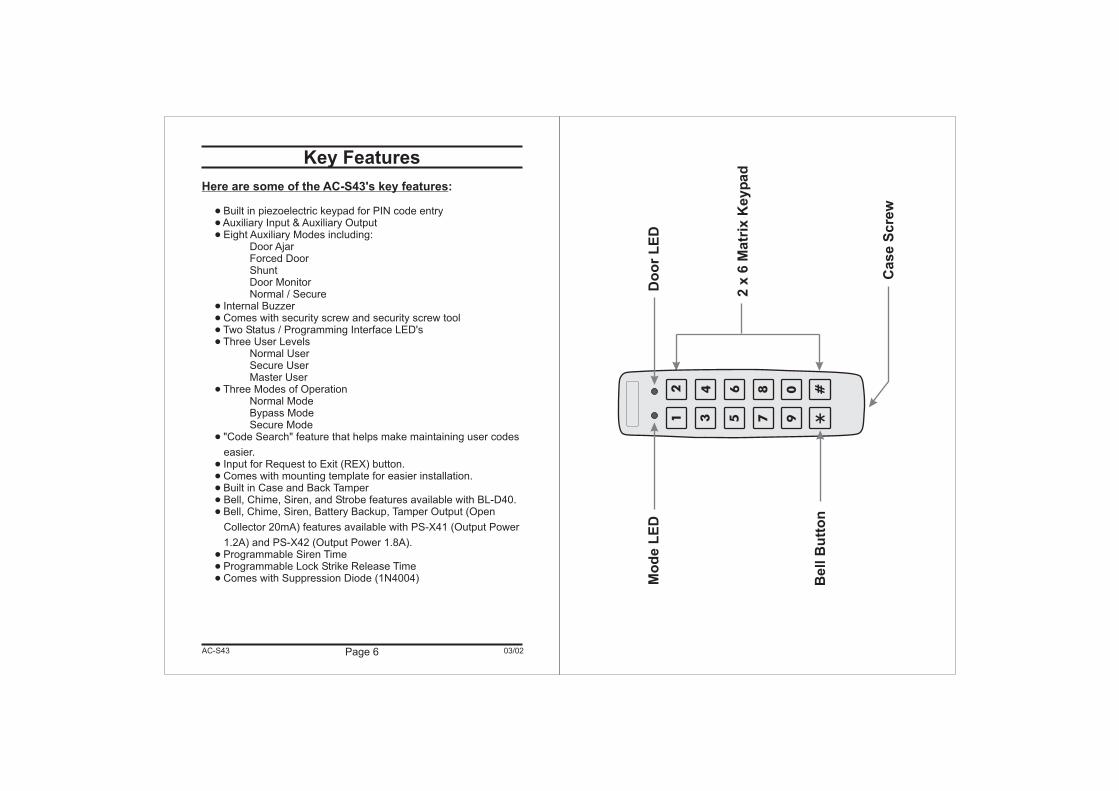
Key Features
Here are some of the AC-S43's key features:
Built in piezoelectric keypad for PIN code entryAuxiliary Input & Auxiliary OutputEight Auxiliary Modes including:
Door AjarForced DoorShuntDoor MonitorNormal / Secure
Internal BuzzerComes with security screw and security screw toolTwo Status / Programming Interface LED'sThree User Levels
Normal UserSecure UserMaster User
Three Modes of OperationNormal ModeBypass ModeSecure Mode
"Code Search" feature that helps make maintaining user codes
easier.Input for Request to Exit (REX) button.Comes with mounting template for easier installation.Built in Case and Back TamperBell, Chime, Siren, and Strobe features available with BL-D40.Bell, Chime, Siren, Battery Backup, Tamper Output (Open
Collector 20mA) features available with PS-X41 (Output Power
1.2A) and PS-X42 (Output Power 1.8A).Programmable Siren TimeProgrammable Lock Strike Release TimeComes with Suppression Diode (1N4004)
�
�
�
�
�
�
�
�
�
�
�
�
�
�
�
�
�
AC-S43
2x
6M
atr
ixK
eyp
ad
Case
Scre
w
12
56
78
90 #
34
Do
or
LE
DM
od
eL
ED
Bell
Bu
tto
n
Page 8 03/02
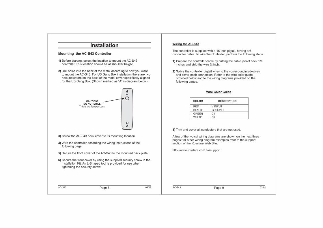
Installation
Mounting the AC-S43 Controller
1)
2)
3)
4)
5)
6)
Before starting, select the location to mount the AC-S43controller. This location should be at shoulder height.
Drill holes into the back of the metal according to how you wantto mount the AC-S43. For US Gang Box installation there are twohole indicators on the back of the metal cover specifically alignedfor the US Gang Box. (Shown marked as ”A” in diagram below).
Screw the AC-S43 back cover to its mounting location.
Wire the controller according the wiring instructions of thefollowing page.
Return the front cover of the AC-S43 to the mounted back plate.
Secure the front cover by using the supplied security screw in theInstallation Kit. An L-Shaped tool is provided for use whentightening the security screw.
AC-S43
A
A
CAUTION!DO NOT DRILL
This is the Tamper Lens
Page 9 03/02
Wiring the AC-S43
Wire Color Guide
The controller is supplied with a 16-inch pigtail, having a 6-conductor cable. To wire the Controller, perform the following steps.
Prepare the controller cable by cutting the cable jacket back 1¼inches and strip the wire ½ inch.
Splice the controller pigtail wires to the corresponding devicesand cover each connection. Refer to the wire color guideprovided below and to the wiring diagrams provided on thefollowing pages.
Trim and cover all conductors that are not used.
A few of the typical wiring diagrams are shown on the next threepages; for other wiring diagram examples refer to the supportsection of the Rosslare Web Site.
http://www.rosslare.com.hk/support
1)
2)
3)
AC-S43
RED
BLACK
GREEN
WHITE
V INPUT
GROUND
C1
C2
COLOR DESCRIPTION
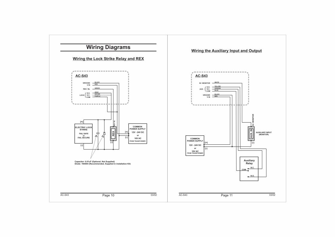
Wiring Diagrams
Wiring the Lock Strike Relay and REX
Page 10 03/0203/02 Page 11AC-S43 AC-S43
(-)
ELECTRIC LOCKSTRIKE
COM
N.C.
N.O.
REX / BL
LOCK
V IN
RE
X/
BL
(-)
(-)
(+)
(+)FAIL SAFE
orFAIL SECURE
RE
X
Capacitor: 0.01uF (Optional, Not Supplied)Diode: 1N4004 (Recommended, Supplied in installation Kit)
COMMONPOWER SUPPLY
12V - 24V DC
or
16V AC
FROM TRANSFORMER
{
GROUNDBLACK
RED
GREEN
GRAY
BROWN
PURPLE
AC-S43
Wiring the Auxiliary Input and Output
IN / MONITOR
V IN
+ -
COMMONPOWER SUPPLY
(-)
(+)12V - 24V DC
or
16V ACFROM TRANSFORMER
COMN.C.
N.O.
AuxiliaryRelay
AUXILIARY INPUT(MONITOR)
(-)
AU
X.
ININ
/M
ON
ITO
R
COM
N.C.
N.O.
AUX. {GROUND
BLACK
RED
WHITE
YELLOW
ORANGE
BLUE
AC-S43
Page 13Page 12 03/0203/02
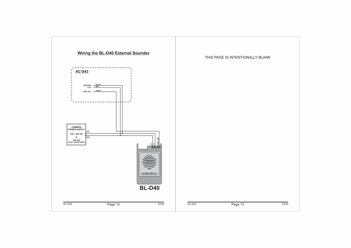
Wiring the BL-D40 External Sounder
AC-S43 AC-S43
REX / BL
RE
X/
BL
(+)
(-)
BL-D40
COMMONPOWER SUPPLY
(-)
(+)
12V - 24V DC
or
16V ACFROM TRANSFORMER
V IN
GROUNDBLACK
RED
GREEN
AC-S43
THIS PAGE IS INTENTIONALLY BLANK
Page 14 03/0203/02
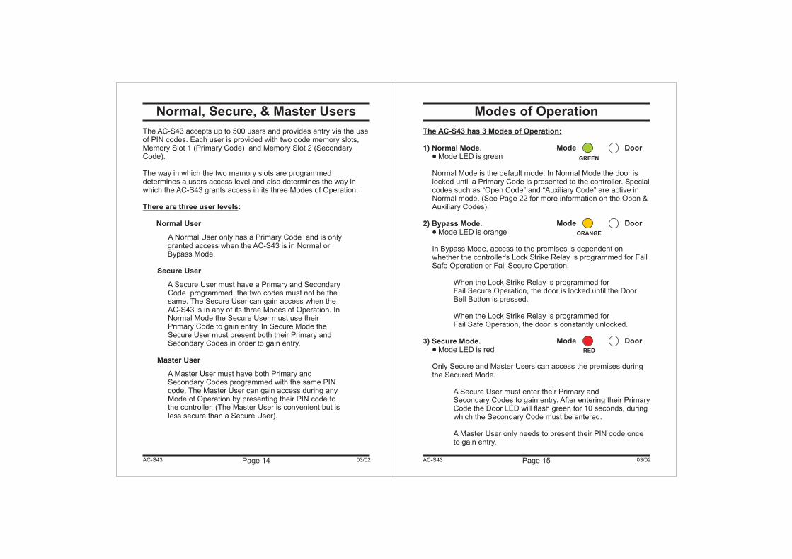
Normal, Secure, & Master Users
The AC-S43 accepts up to 500 users and provides entry via the useof PIN codes. Each user is provided with two code memory slots,Memory Slot 1 (Primary Code) and Memory Slot 2 (SecondaryCode).
The way in which the two memory slots are programmeddetermines a users access level and also determines the way inwhich the AC-S43 grants access in its three Modes of Operation.
A Normal User only has a Primary Code and is onlygranted access when the AC-S43 is in Normal orBypass Mode.
A Secure User must have a Primary and SecondaryCode programmed, the two codes must not be thesame. The Secure User can gain access when theAC-S43 is in any of its three Modes of Operation. InNormal Mode the Secure User must use theirPrimary Code to gain entry. In Secure Mode theSecure User must present both their Primary andSecondary Codes in order to gain entry.
A Master User must have both Primary andSecondary Codes programmed with the same PINcode. The Master User can gain access during anyMode of Operation by presenting their PIN code tothe controller. (The Master User is convenient but isless secure than a Secure User).
There are three user levels:
Normal User
Secure User
Master User
Modes of Operation
�
The AC-S43 has 3 Modes of Operation:
1) Normal Mode
2) Bypass Mode.
3) Secure Mode.
.Mode LED is green
Normal Mode is the default mode. In Normal Mode the door islocked until a Primary Code is presented to the controller. Specialcodes such as “Open Code” and “Auxiliary Code” are active inNormal mode. (See Page 22 for more information on the Open &Auxiliary Codes).
Mode LED is orange
In Bypass Mode, access to the premises is dependent onwhether the controller's Lock Strike Relay is programmed for FailSafe Operation or Fail Secure Operation.
When the Lock Strike Relay is programmed forFail Secure Operation, the door is locked until the DoorBell Button is pressed.
When the Lock Strike Relay is programmed forFail Safe Operation, the door is constantly unlocked.
Mode LED is red
Only Secure and Master Users can access the premises duringthe Secured Mode.
A Secure User must enter their Primary andSecondary Codes to gain entry. After entering their PrimaryCode the Door LED will flash green for 10 seconds, duringwhich the Secondary Code must be entered.
A Master User only needs to present their PIN code onceto gain entry.
�
�
Page 15AC-S43 AC-S43
Mode Door
GREEN
Mode Door
ORANGE
Mode Door
RED
Page 16 03/0203/02
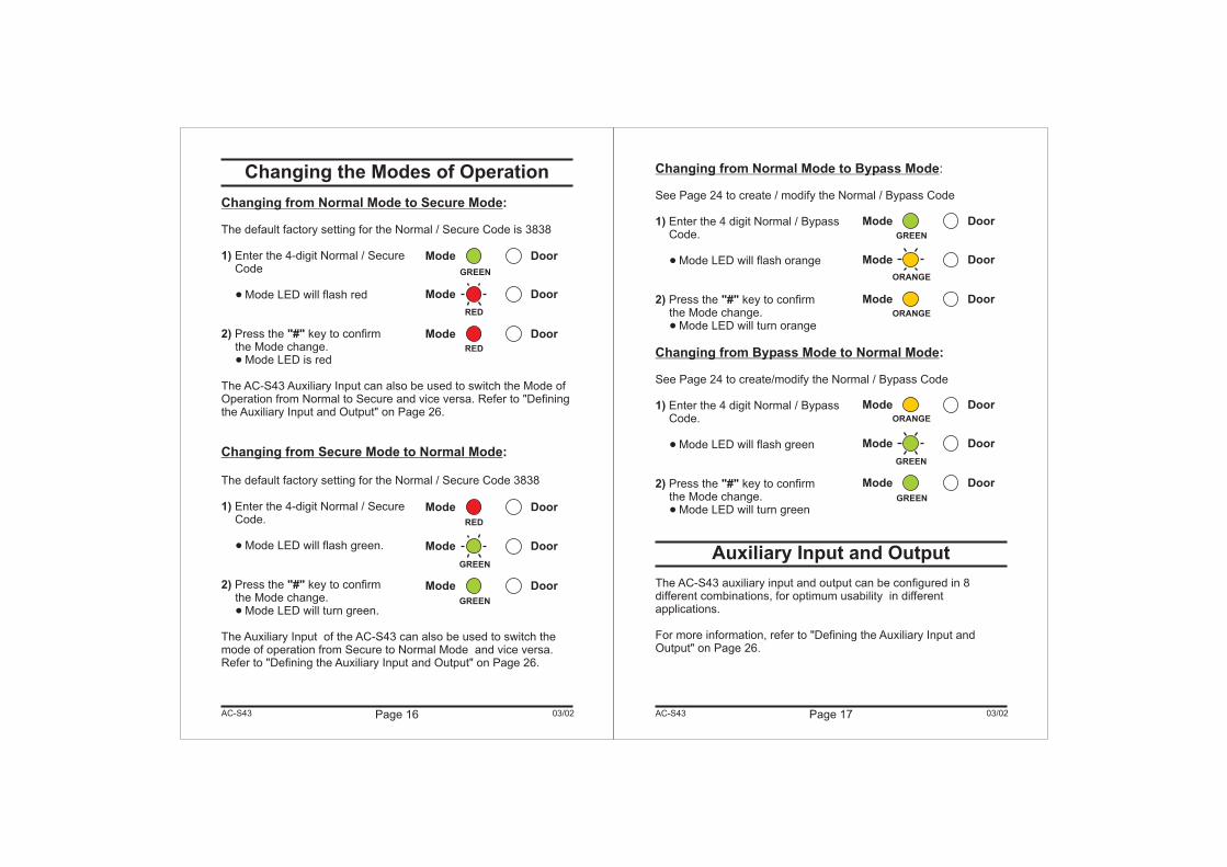
Changing the Modes of Operation
Changing from Normal Mode to Secure Mode
Changing from Secure Mode to Normal Mode
:
:
The default factory setting for the Normal / Secure Code is 3838
Enter the 4-digit Normal / SecureCode
Mode LED will flash red
Press the key to confirmthe Mode change.
Mode LED is red
The AC-S43 Auxiliary Input can also be used to switch the Mode ofOperation from Normal to Secure and vice versa. Refer to "Definingthe Auxiliary Input and Output" on Page 26.
The default factory setting for the Normal / Secure Code 3838
Enter the 4-digit Normal / SecureCode.
Mode LED will flash green.
Press the key to confirmthe Mode change.
Mode LED will turn green.
The Auxiliary Input of the AC-S43 can also be used to switch themode of operation from Secure to Normal Mode and vice versa.Refer to "Defining the Auxiliary Input and Output" on Page 26.
1)
2) "#"
1)
2) "#"
�
�
�
�
Changing from Normal Mode to Bypass Mode
Changing from Bypass Mode to Normal Mode
:
See Page 24 to create / modify the Normal / Bypass Code
Enter the 4 digit Normal / BypassCode.
Mode LED will flash orange
Press the key to confirmthe Mode change.
Mode LED will turn orange
See Page 24 to create/modify the Normal / Bypass Code
Enter the 4 digit Normal / BypassCode.
Mode LED will flash green
Press the key to confirmthe Mode change.
Mode LED will turn green
The AC-S43 auxiliary input and output can be configured in 8different combinations, for optimum usability in differentapplications.
For more information, refer to "Defining the Auxiliary Input andOutput" on Page 26.
1)
2) "#"
1)
2) "#"
�
�
�
�
:
Auxiliary Input and Output
Page 17AC-S43 AC-S43
Mode Door
GREEN
Mode Door
Mode Door
GREEN
Mode Door
RED
Mode Door
RED
Mode Door
Mode Door
Mode Door
RED
GREEN
GREEN
Mode Door
ORANGE
Mode Door
GREEN
Mode Door
ORANGE
Mode DoorORANGE
GREEN
Page 18 03/0203/02
Request to Exit (REX) Button
Case and Back Tamper
The REX button must be located inside the premises to be securedand is used to open the door without the use of a proximity card orPIN code, it is usually located in a convenient location, e.g. Insidethe door or at a receptionist's desk. The function of the REX buttondepends on whether the Lock Strike Relay is programmed for FailSafe Operation or Fail Secure Operation. The door chime in the BL-D40 does not sound when the REX button is used to open the door.
Fail Secure Operation: From the moment the REX button ispressed, the door will be unlocked until the "Lock Strike ReleaseTime" has passed. After this time, the door will be locked even ifthe REX button has not been released.
Fail Safe Operation: From the moment the REX button ispressed, the door will be unlocked until the REX button isreleased, plus the "Lock Strike Release Time". In this case the"Lock Strike Relay" only begins its count down once the REXbutton has been released.
If the case of the controller is opened or the controller is removedfrom the wall, a tamper event is triggered and a coded tampersignal is sent to a BL-D40, PS-X41 Series or PS-X42 Series PowerSupply, or other compatible device.
If the BL-D40 External Sounder , PS-X41 Series or PS-X42 SeriesPower Supplies receive a Tamper Event Signal, they will activate aSiren and if available a Strobe Light. The Siren time can be easilyprogrammed in the AC-S43 from 0 to 9 minutes.
Clearing a tamper event is done by entering a valid User or OpenCode that will open the Lock Strike Output in the current Mode ofOperation. For example, while in Secure Mode, using the OpenCode to clear tamper event will not work because the Open Codedoes not work in Secure Mode. However, applying a Master Codeor Secure Code will clear the tamper event in Secure Mode.
1)
2)
BL-D40 External Sounder
The BL-D40 External Sounder is compatible with the AC-X31, AC-X32, AC-X41, and AC-X42 series Standalone Controllers (For amore up-to-date list of compatible products check the Rosslare WebSite at www.rosslare.com.hk). It is designed to operate indoors andinstalled within the premises to be secured. The Sounder can bepowered by 16V AC or 12 to 24V DC power supply.
The BL-D40 is capable of emitting four different types of alerts bothaudible and visual; Bell, Door Chime, Siren, and Strobe Light.
The Bell always sounds when the controller's doorbell buttonis pressed.
The Door Chime can be programmed to sound whenever thecontroller unlocks the door (the Door Chime does not soundwhen the REX button is used to open the door).
The Siren can be programmed to sound when the case of thecontroller is opened or when the controller is removed from thewall. The controller can also program the length of the Siren inthe BL-D40.
The Controller communicates with the BL-D40 using a codedproprietary Rosslare communications protocol. This provides amore secure link between the Controller and the BL-D40. If the BL-D40 receives any unrecognized codes on its communication line orcommunication between the controller and the BL-D40 are severed,the Strobe with flash repeatedly until the communication problemhas been resolved.
1)
2)
3)
Page 19AC-S43 AC-S43
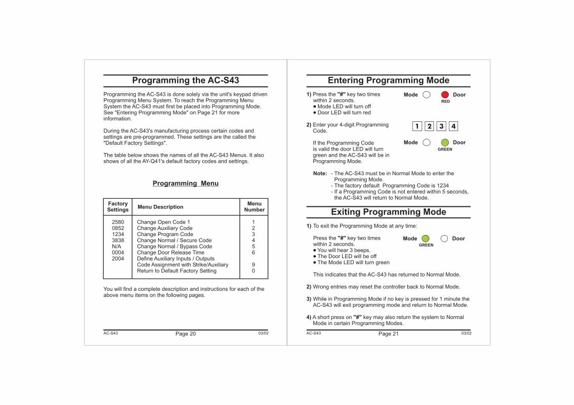
Programming the AC-S43
Programming the AC-S43 is done solely via the unit's keypad drivenProgramming Menu System. To reach the Programming MenuSystem the AC-S43 must first be placed into Programming Mode.See "Entering Programming Mode" on Page 21 for moreinformation.
During the AC-S43's manufacturing process certain codes andsettings are pre-programmed. These settings are the called the"Default Factory Settings".
The table below shows the names of all the AC-S43 Menus. It alsoshows of all the AY-Q41's default factory codes and settings.
2580 Change Open Code 1 10852 Change Auxiliary Code 21234 Change Program Code 33838 Change Normal / Secure Code 4N/A Change Normal / Bypass Code 50004 Change Door Release Time 62004 Define Auxiliary Inputs / Outputs
Code Assignment with Strike/Auxiliary 9Return to Default Factory Setting 0
You will find a complete description and instructions for each of theabove menu items on the following pages.
Programming Menu
Page 20 03/02AC-S43
Menu DescriptionFactorySettings
MenuNumber
Page 21 03/02
Entering Programming Mode
Exiting Programming Mode
1) "#"
2)
Note:
1)
"#"
2)
3)
4) "#"
Press the key two timeswithin 2 seconds.
Mode LED will turn offDoor LED will turn red
Enter your 4-digit ProgrammingCode.
If the Programming Codeis valid the door LED will turngreen and the AC-S43 will be inProgramming Mode.
- The AC-S43 must be in Normal Mode to enter theProgramming Mode.
- The factory default Programming Code is 1234- If a Programming Code is not entered within 5 seconds,
the AC-S43 will return to Normal Mode.
To exit the Programming Mode at any time:
Press the key two timeswithin 2 seconds.
You will hear 3 beeps.The Door LED will be offThe Mode LED will turn green
This indicates that the AC-S43 has returned to Normal Mode.
Wrong entries may reset the controller back to Normal Mode.
While in Programming Mode if no key is pressed for 1 minute theAC-S43 will exit programming mode and return to Normal Mode.
A short press on key may also return the system to NormalMode in certain Programming Modes.
�
�
�
�
�
AC-S43
Mode Door
Mode DoorGREEN
RED
1 2 3 4
Mode Door
GREEN
Changing the Open Code
Changing the Auxiliary Code
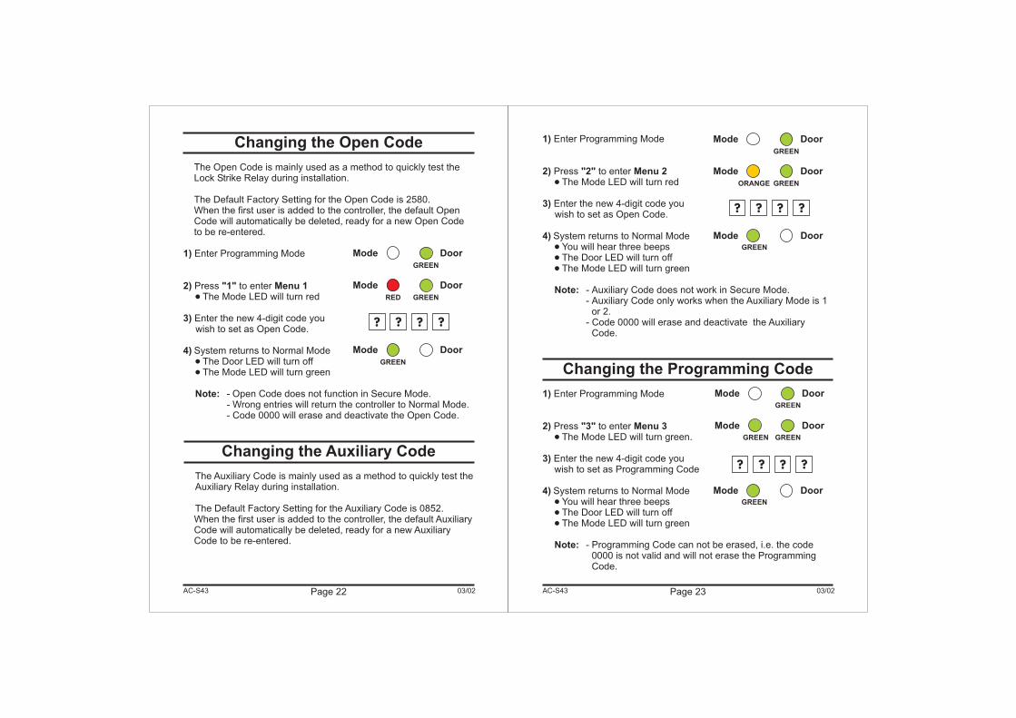
The Open Code is mainly used as a method to quickly test theLock Strike Relay during installation.
The Default Factory Setting for the Open Code is 2580.When the first user is added to the controller, the default OpenCode will automatically be deleted, ready for a new Open Codeto be re-entered.
Enter Programming Mode
Press to enterThe Mode LED will turn red
Enter the new 4-digit code youwish to set as Open Code.
System returns to Normal ModeThe Door LED will turn offThe Mode LED will turn green
- Open Code does not function in Secure Mode.- Wrong entries will return the controller to Normal Mode.- Code 0000 will erase and deactivate the Open Code.
The Auxiliary Code is mainly used as a method to quickly test theAuxiliary Relay during installation.
The Default Factory Setting for the Auxiliary Code is 0852.When the first user is added to the controller, the default AuxiliaryCode will automatically be deleted, ready for a new AuxiliaryCode to be re-entered.
1)
2) "1" Menu 1
3)
4)
Note:
�
�
�
Page 22 03/02AC-S43 Page 23 03/02
1)
2) "2" Menu 2
3)
4)
Note:
1)
2) "3" Menu 3
3)
4)
Note:
Enter Programming Mode
Press to enterThe Mode LED will turn red
Enter the new 4-digit code youwish to set as Open Code.
System returns to Normal ModeYou will hear three beepsThe Door LED will turn offThe Mode LED will turn green
- Auxiliary Code does not work in Secure Mode.- Auxiliary Code only works when the Auxiliary Mode is 1
or 2.- Code 0000 will erase and deactivate the Auxiliary
Code.
Enter Programming Mode
Press to enterThe Mode LED will turn green.
Enter the new 4-digit code youwish to set as Programming Code
System returns to Normal ModeYou will hear three beepsThe Door LED will turn offThe Mode LED will turn green
- Programming Code can not be erased, i.e. the code0000 is not valid and will not erase the ProgrammingCode.
�
�
�
�
�
�
�
�
Changing the Programming Code
AC-S43
Mode Door
Mode DoorGREEN
GREEN
Mode Door
GREEN
Mode Door
GREENRED
? ? ? ?
Mode Door
GREEN
Mode DoorGREENGREEN
? ? ? ?
Mode DoorGREEN
Mode Door
GREEN
Mode Door
GREEN
? ? ? ?
ORANGE
Changing the Normal / Secure Code
Changing the Normal / Bypass Codeand Door Chime Settings
1)
2) "4" Menu 4
3)
4)
Note:
1)
2) "5" Menu 5
3)
a)b)c)d)
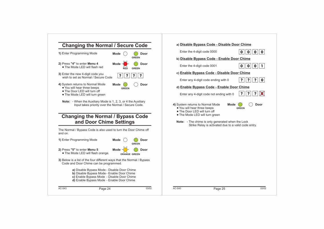
Enter Programming Mode
Press to enterThe Mode LED will flash red
Enter the new 4-digit code youwish to set as Normal / Secure Code
System returns to Normal ModeYou will hear three beepsThe Door LED will turn offThe Mode LED will turn green
- When the Auxiliary Mode is 1, 2, 3, or 4 the AuxiliaryInput takes priority over the Normal / Secure Code.
The Normal / Bypass Code is also used to turn the Door Chime offand on.
Enter Programming Mode
Press to enterThe Mode LED will flash orange.
Below is a list of the four different ways that the Normal / BypassCode and Door Chime can be programmed.
Disable Bypass Mode - Disable Door ChimeDisable Bypass Mode - Enable Door ChimeEnable Bypass Mode - Disable Door ChimeEnable Bypass Mode - Enable Door Chime
�
�
�
�
�
Page 24 03/02AC-S43 Page 25 03/02
a)
b)
c)
d)
4)
Note:
Disable Bypass Code - Disable Door Chime
Disable Bypass Code - Enable Door Chime
Enable Bypass Code - Disable Door Chime
Enable Bypass Code - Enable Door Chime
Enter the 4-digit code 0000
Enter the 4-digit code 0001
Enter any 4-digit code ending with 0
Enter any 4-digit code not ending with 0
System returns to Normal ModeYou will hear three beepsThe Door LED will turn offThe Mode LED will turn green
- The chime is only generated when the LockStrike Relay is activated due to a valid code entry.
�
�
�
AC-S43
Mode DoorGREEN
Mode Door
GREEN
Mode Door
GREENRED
? ? ? ?
Mode Door
GREEN
Mode Door
GREEN
Mode Door
GREENORANGE
0 0 0 1
0 0 0 0
? ? ? 0
? ? ? 0
Page 26 03/02
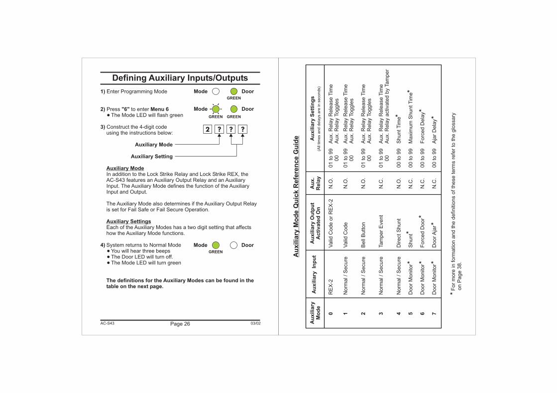
Defining Auxiliary Inputs/Outputs
1)
2) "6" Menu 6
3)
Auxiliary Mode
Auxiliary Setting
4)
The definitions for the Auxiliary Modes can be found in thetable on the next page.
Enter Programming Mode
Press to enterThe Mode LED will flash green
Construct the 4-digit codeusing the instructions below:
In addition to the Lock Strike Relay and Lock Strike REX, theAC-S43 features an Auxiliary Output Relay and an AuxiliaryInput. The Auxiliary Mode defines the function of the AuxiliaryInput and Output.
The Auxiliary Mode also determines if the Auxiliary Output Relayis set for Fail Safe or Fail Secure Operation.
Each of the Auxiliary Modes has a two digit setting that affectshow the Auxiliary Mode functions.
System returns to Normal ModeYou will hear three beepsThe Door LED will turn off.The Mode LED will turn green
�
�
�
�
Auxiliary Mode
Auxiliary Settings
AC-S43
Mode Door
GREEN
Mode Door
GREENGREEN
2 ? ? ?
Mode Door
GREEN
Au
xilia
ryM
od
e
Au
xilia
ryM
od
eQ
uic
kR
efe
ren
ce
Gu
ide
RE
X-2
Valid
Code
or
RE
X-2
N.O
.01
to99
Aux.R
ela
yR
ele
ase
Tim
e00
Aux.R
ela
yToggle
s
Norm
al/S
ecure
Valid
Code
N.O
.01
to99
Aux.R
ela
yR
ele
ase
Tim
e00
Aux.R
ela
yToggle
s
Norm
al/S
ecure
Bell
Button
N.O
.01
to99
Aux.R
ela
yR
ele
ase
Tim
e00
Aux.R
ela
yToggle
s
Norm
al/S
ecure
Tam
per
Event
N.C
.01
to99
Aux.R
ela
yR
ele
ase
Tim
e00
Aux.R
ela
yactivate
dby
Tam
per
Norm
al/S
ecure
DirectS
hunt
N.O
.00
to99
ShuntT
ime
Door
Monitor
Shunt
N.C
.00
to99
Maxim
um
ShuntT
ime
Door
Monitor
Forc
ed
Door
N.C
.00
to99
Forc
ed
Dela
y
Door
Monitor
Door
Aja
rN
.C.
00
to99
Aja
rD
ela
y
For
more
info
rmation
and
the
definitio
ns
ofth
ese
term
sre
fer
toth
eglo
ssary
on
Page
38.
0 1 2 3 4 5 6 7
*Au
xilia
ryIn
pu
tA
uxilia
ryO
utp
ut
Acti
vate
dO
nA
uxilia
ryS
ett
ing
sA
ux.
Rela
y(A
lltim
es
and
dela
ys
are
inseconds)
***
**
*
*
*
*
*
Page 29 03/02
Enrolling Primary & Secondary Codes
Primary Codes
Secondary Codes
Enrolling Primary and Secondary Codes
- Primary Codes can only be enrolled to an empty User Slot, i.e aslot where there is no existing Primary Code.
- Primary Codes must be unique, i.e. one users Primary Codemay not be the same as another users Primary Code.
- Primary Codes cannot be the same as any system codes, suchas the Normal / Secure Code or Open Code.
- Users who hold a Primary Code can gain entry only duringNormal Mode.
- Secondary Codes can only be enrolled to User Slot that alreadyhas a Primary Code enrolled but no Secondary Code.
- Secondary Codes do not have to be unique, i.e. multiple userscan all hold the same Secondary Code.
- Secondary Codes cannot be the same as any system codes,such as the Normal / Secure Code or Open Code.
- Users who hold Secondary Codes can gain entry in any Modeof Operation.
There are two methods to enroll Primary and Secondarycodes, the Standard Method and the Code Search Method.
A. The Standard Method is mainly used when the User Slotnumber for the user you wish to program is known. You canprogram both Primary and Secondary Codes using theStandard method. (See Enrolling Users with the StandardMethod on Page 30)
B. The Code Search Method is mainly used when enrolling ausers Secondary Code and the User Slot Code is unknown.The Code Search method only works if a users Primary Codeis already enrolled but the Secondary Code is not. (SeeEnrolling Users with the Code Search Method on Page 31)
AC-S43
Setting Fail Safe/Secure OperationSetting Tamper Siren Time
Setting the Lock Strike Release Time
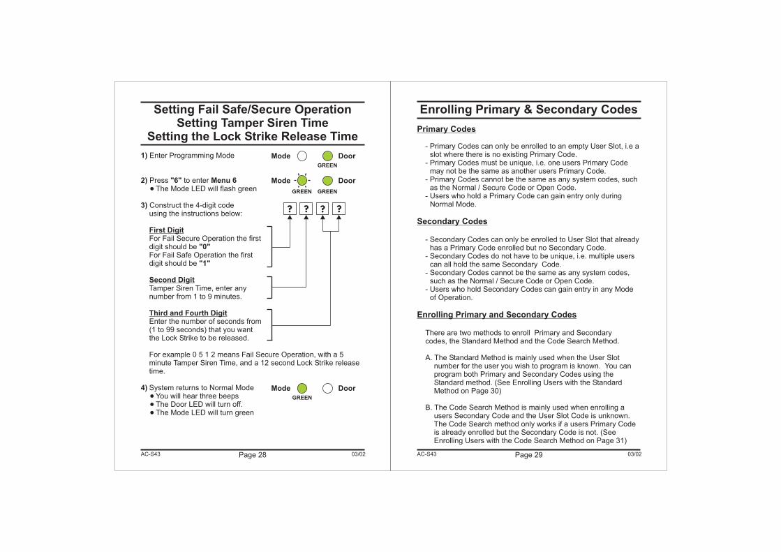
1)
2) "6" Menu 6
3)
"0"
"1"
4)
Enter Programming Mode
Press to enterThe Mode LED will flash green
Construct the 4-digit codeusing the instructions below:
For Fail Secure Operation the firstdigit should beFor Fail Safe Operation the firstdigit should be
Tamper Siren Time, enter anynumber from 1 to 9 minutes.
Enter the number of seconds from(1 to 99 seconds) that you wantthe Lock Strike to be released.
For example 0 5 1 2 means Fail Secure Operation, with a 5minute Tamper Siren Time, and a 12 second Lock Strike releasetime.
System returns to Normal ModeYou will hear three beepsThe Door LED will turn off.The Mode LED will turn green
�
�
�
�
First Digit
Second Digit
Third and Fourth Digit
Page 28 03/02AC-S43
Mode Door
GREEN
Mode Door
GREEN
Mode Door
GREEN
GREEN
? ? ? ?
Page 31 03/02
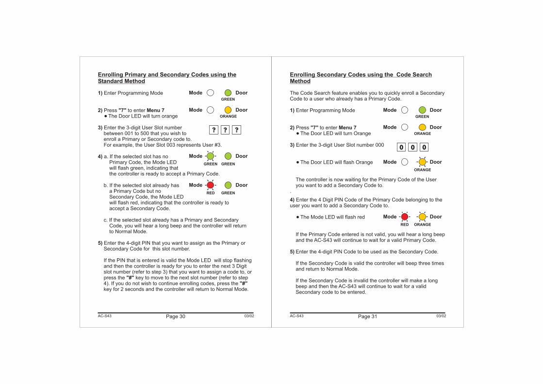
Enrolling Secondary Codes using the Code SearchMethod
The Code Search feature enables you to quickly enroll a SecondaryCode to a user who already has a Primary Code.
Enter Programming Mode
Press to enterThe Door LED will turn Orange
Enter the 3-digit User Slot number 000
The Door LED will flash Orange
The controller is now waiting for the Primary Code of the Useryou want to add a Secondary Code to.
.
Enter the 4 Digit PIN Code of the Primary Code belonging to theuser you want to add a Secondary Code to.
The Mode LED will flash red
If the Primary Code entered is not valid, you will hear a long beepand the AC-S43 will continue to wait for a valid Primary Code.
Enter the 4-digit PIN Code to be used as the Secondary Code.
If the Secondary Code is valid the controller will beep three timesand return to Normal Mode.
If the Secondary Code is invalid the controller will make a longbeep and then the AC-S43 will continue to wait for a validSecondary code to be entered.
1)
2) "7" Menu 7
3)
4)
5)
�
�
�
AC-S43
Enrolling Primary and Secondary Codes using theStandard Method
1)
2) "7" Menu 7
3)
4)
5)
"#""#"
Enter Programming Mode
Press to enterThe Door LED will turn orange
Enter the 3-digit User Slot numberbetween 001 to 500 that you wish toenroll a Primary or Secondary code to.For example, the User Slot 003 represents User #3.
a. If the selected slot has noPrimary Code, the Mode LEDwill flash green, indicating thatthe controller is ready to accept a Primary Code.
b. If the selected slot already hasa Primary Code but noSecondary Code, the Mode LEDwill flash red, indicating that the controller is ready toaccept a Secondary Code.
c. If the selected slot already has a Primary and SecondaryCode, you will hear a long beep and the controller will returnto Normal Mode.
Enter the 4-digit PIN that you want to assign as the Primary orSecondary Code for this slot number.
If the PIN that is entered is valid the Mode LED will stop flashingand then the controller is ready for you to enter the next 3 Digitslot number (refer to step 3) that you want to assign a code to, orpress the key to move to the next slot number (refer to step4). If you do not wish to continue enrolling codes, press thekey for 2 seconds and the controller will return to Normal Mode.
�
Page 30 03/02AC-S43
Mode Door
GREEN
Mode DoorORANGE
? ? ?
Mode Door
GREEN GREEN
Mode Door
RED GREEN
Mode Door
GREEN
Mode DoorORANGE
0 0 0
Mode Door
ORANGE
Mode Door
RED ORANGE
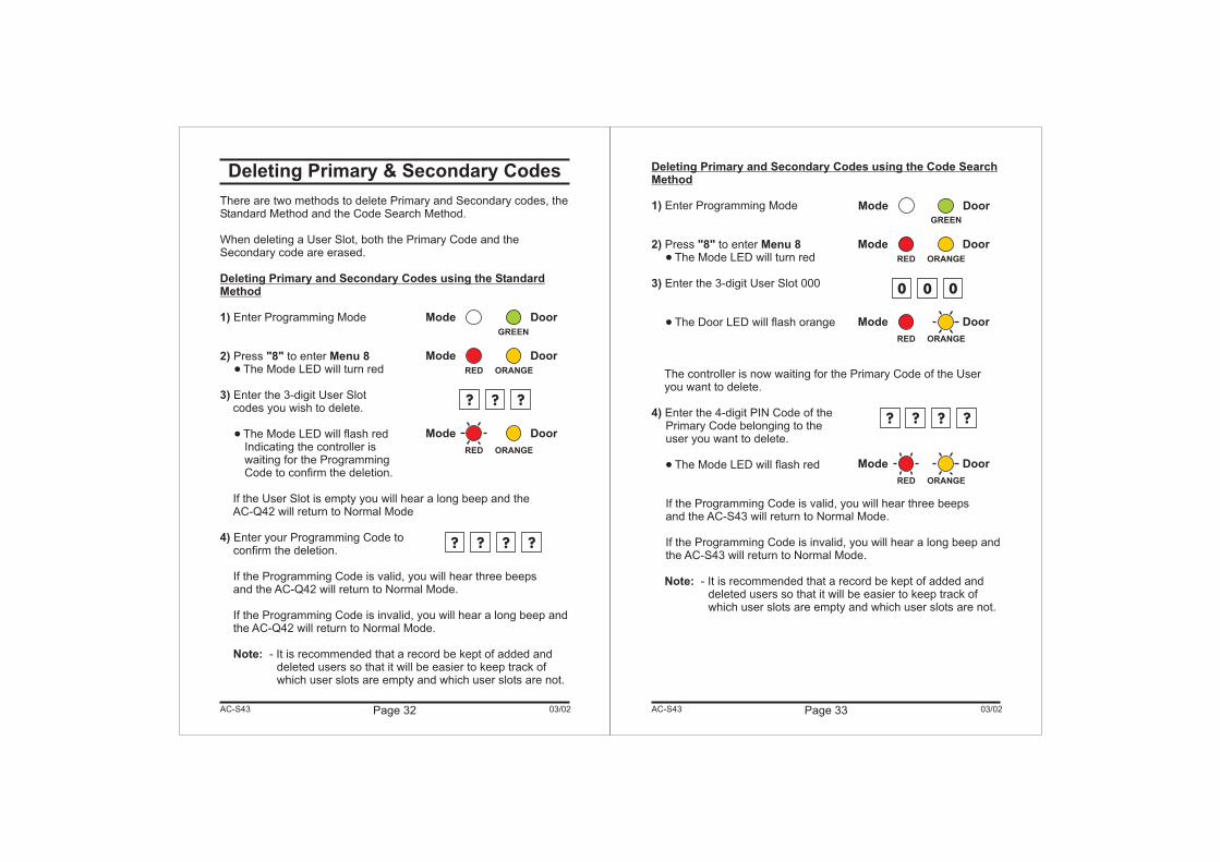
Deleting Primary & Secondary Codes
There are two methods to delete Primary and Secondary codes, theStandard Method and the Code Search Method.
When deleting a User Slot, both the Primary Code and theSecondary code are erased.
Enter Programming Mode
Press to enterThe Mode LED will turn red
Enter the 3-digit User Slotcodes you wish to delete.
The Mode LED will flash redIndicating the controller iswaiting for the ProgrammingCode to confirm the deletion.
If the User Slot is empty you will hear a long beep and theAC-Q42 will return to Normal Mode
Enter your Programming Code toconfirm the deletion.
If the Programming Code is valid, you will hear three beepsand the AC-Q42 will return to Normal Mode.
If the Programming Code is invalid, you will hear a long beep andthe AC-Q42 will return to Normal Mode.
- It is recommended that a record be kept of added anddeleted users so that it will be easier to keep track ofwhich user slots are empty and which user slots are not.
Deleting Primary and Secondary Codes using the StandardMethod
1)
2) "8" Menu 8
3)
4)
Note:
�
�
Page 32 03/02AC-S43 Page 33 03/02
Deleting Primary and Secondary Codes using the Code SearchMethod
1)
2) "8" Menu 8
3)
4)
Note:
Enter Programming Mode
Press to enterThe Mode LED will turn red
Enter the 3-digit User Slot 000
The Door LED will flash orange
The controller is now waiting for the Primary Code of the Useryou want to delete.
Enter the 4-digit PIN Code of thePrimary Code belonging to theuser you want to delete.
The Mode LED will flash red
If the Programming Code is valid, you will hear three beepsand the AC-S43 will return to Normal Mode.
If the Programming Code is invalid, you will hear a long beep andthe AC-S43 will return to Normal Mode.
- It is recommended that a record be kept of added anddeleted users so that it will be easier to keep track ofwhich user slots are empty and which user slots are not.
�
�
�
AC-S43
Mode DoorGREEN
Mode Door
GREEN
Mode Door
ORANGERED
? ? ?
Mode Door
? ? ? ?
ORANGERED
Mode Door
ORANGERED
0 0 0
Mode Door
ORANGERED
? ? ? ?
Mode Door
ORANGERED
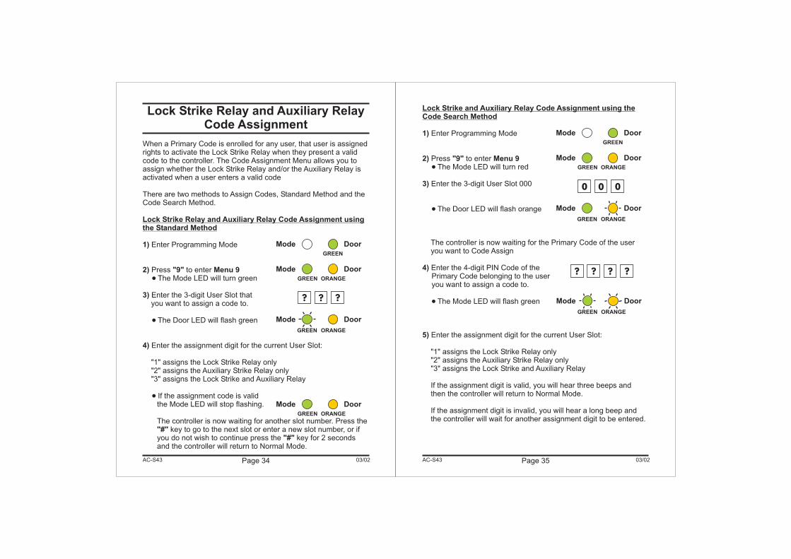
Lock Strike Relay and Auxiliary RelayCode Assignment
When a Primary Code is enrolled for any user, that user is assignedrights to activate the Lock Strike Relay when they present a validcode to the controller. The Code Assignment Menu allows you toassign whether the Lock Strike Relay and/or the Auxiliary Relay isactivated when a user enters a valid code
There are two methods to Assign Codes, Standard Method and theCode Search Method.
Enter Programming Mode
Press to enterThe Mode LED will turn green
Enter the 3-digit User Slot thatyou want to assign a code to.
The Door LED will flash green
Enter the assignment digit for the current User Slot:
"1" assigns the Lock Strike Relay only"2" assigns the Auxiliary Strike Relay only"3" assigns the Lock Strike and Auxiliary Relay
If the assignment code is validthe Mode LED will stop flashing.
The controller is now waiting for another slot number. Press thekey to go to the next slot or enter a new slot number, or if
you do not wish to continue press the key for 2 secondsand the controller will return to Normal Mode.
Lock Strike Relay and Auxiliary Relay Code Assignment usingthe Standard Method
1)
2) "9" Menu 9
3)
4)
"#""#"
�
�
�
Page 34 03/02AC-S43 Page 35 03/02
Lock Strike and Auxiliary Relay Code Assignment using theCode Search Method
1)
2) "9" Menu 9
3)
4)
5)
Enter Programming Mode
Press to enterThe Mode LED will turn red
Enter the 3-digit User Slot 000
The Door LED will flash orange
The controller is now waiting for the Primary Code of the useryou want to Code Assign
Enter the 4-digit PIN Code of thePrimary Code belonging to the useryou want to assign a code to.
The Mode LED will flash green
Enter the assignment digit for the current User Slot:
"1" assigns the Lock Strike Relay only"2" assigns the Auxiliary Strike Relay only"3" assigns the Lock Strike and Auxiliary Relay
If the assignment digit is valid, you will hear three beeps andthen the controller will return to Normal Mode.
If the assignment digit is invalid, you will hear a long beep andthe controller will wait for another assignment digit to be entered.
�
�
�
AC-S43
Mode Door
GREEN
Mode Door
ORANGEGREEN
? ? ?
Mode Door
ORANGEGREEN
? ? ? ?
Mode Door
ORANGEGREEN
Mode Door
ORANGEGREEN
Mode Door
GREEN
Mode Door
ORANGEGREEN
0 0 0
Mode Door
ORANGEGREEN
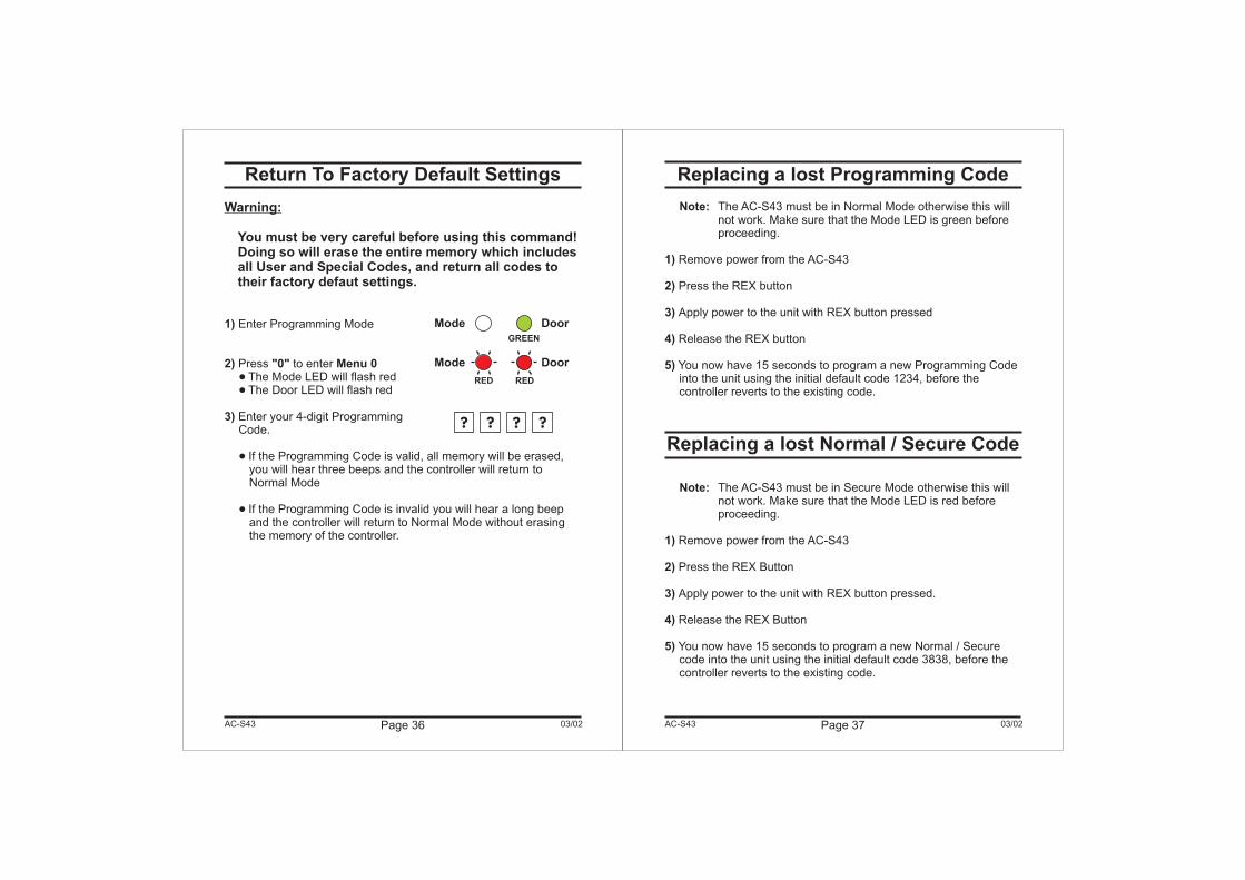
Return To Factory Default Settings
Warning:
You must be very careful before using this command!Doing so will erase the entire memory which includesall User and Special Codes, and return all codes totheir factory defaut settings.
1)
2) "0" Menu 0
3)
Enter Programming Mode
Press to enterThe Mode LED will flash redThe Door LED will flash red
Enter your 4-digit ProgrammingCode.
If the Programming Code is valid, all memory will be erased,you will hear three beeps and the controller will return toNormal Mode
If the Programming Code is invalid you will hear a long beepand the controller will return to Normal Mode without erasingthe memory of the controller.
�
�
�
�
Page 36 03/02AC-S43 Page 37 03/02
Replacing a lost Programming Code
Replacing a lost Normal / Secure Code
1)
2)
3)
4)
5)
1)
2)
3)
4)
5)
Remove power from the AC-S43
Press the REX button
Apply power to the unit with REX button pressed
Release the REX button
You now have 15 seconds to program a new Programming Codeinto the unit using the initial default code 1234, before thecontroller reverts to the existing code.
Remove power from the AC-S43
Press the REX Button
Apply power to the unit with REX button pressed.
Release the REX Button
You now have 15 seconds to program a new Normal / Securecode into the unit using the initial default code 3838, before thecontroller reverts to the existing code.
Note:
Note:
The AC-S43 must be in Normal Mode otherwise this willnot work. Make sure that the Mode LED is green beforeproceeding.
The AC-S43 must be in Secure Mode otherwise this willnot work. Make sure that the Mode LED is red beforeproceeding.
AC-S43
Mode Door
GREEN
Mode Door
REDRED
? ? ? ?
Glossary
A
B
C
D
F
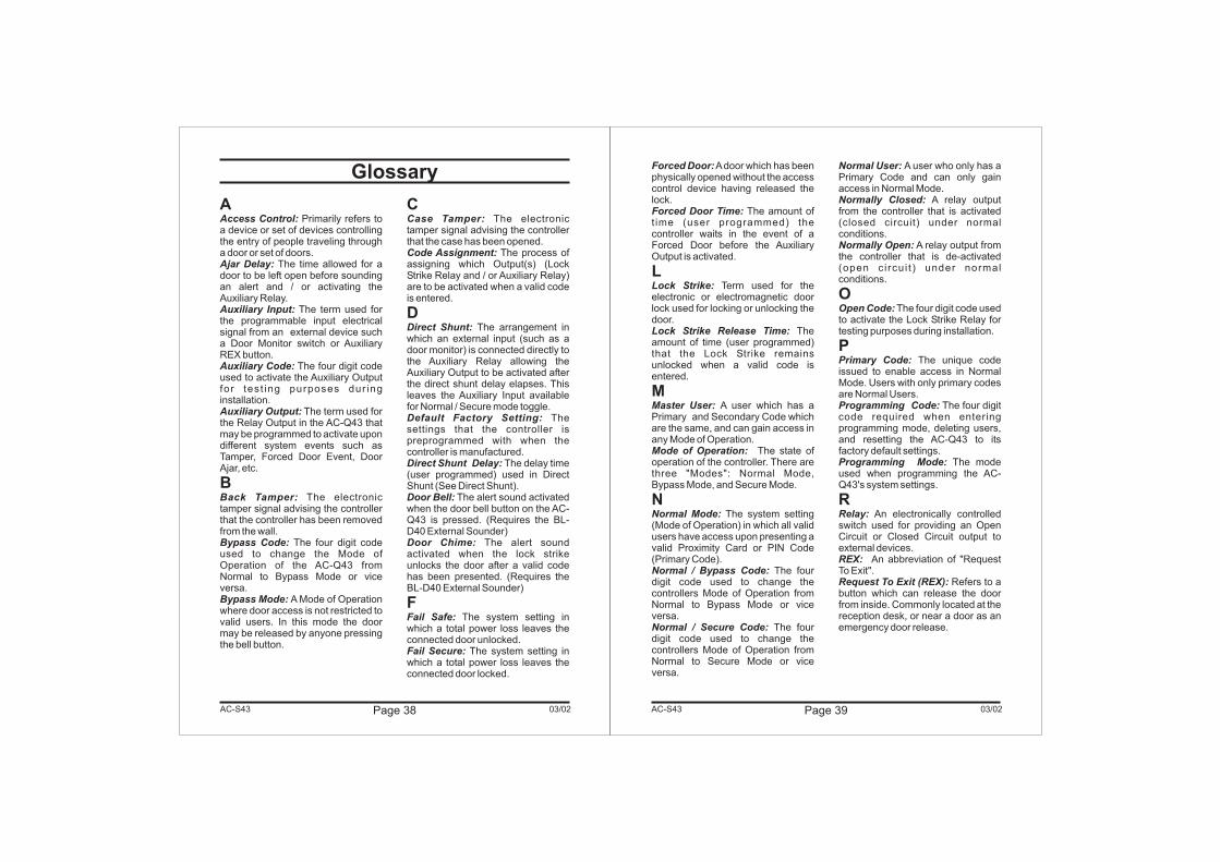
Access Control:
Ajar Delay:
Auxiliary Input:
Auxiliary Code:
Auxiliary Output:
Back Tamper:
Bypass Code:
Bypass Mode:
Case Tamper:
Code Assignment:
Direct Shunt:
Default Factory Setting:
Direct Shunt Delay:
Door Bell:
Door Chime:
Fail Safe:
Fail Secure:
Primarily refers toa device or set of devices controllingthe entry of people traveling througha door or set of doors.
The time allowed for adoor to be left open before soundingan alert and / or activating theAuxiliary Relay.
The term used forthe programmable input electricalsignal from an external device sucha Door Monitor switch or AuxiliaryREX button.
The four digit codeused to activate the Auxiliary Outputfor test ing purposes dur inginstallation.
The term used forthe Relay Output in the AC-Q43 thatmay be programmed to activate upondifferent system events such asTamper, Forced Door Event, DoorAjar, etc.
The electronictamper signal advising the controllerthat the controller has been removedfrom the wall.
The four digit codeused to change the Mode ofOperation of the AC-Q43 fromNormal to Bypass Mode or viceversa.
A Mode of Operationwhere door access is not restricted tovalid users. In this mode the doormay be released by anyone pressingthe bell button.
The electronictamper signal advising the controllerthat the case has been opened.
The process ofassigning which Output(s) (LockStrike Relay and / or Auxiliary Relay)are to be activated when a valid codeis entered.
The arrangement inwhich an external input (such as adoor monitor) is connected directly tothe Auxiliary Relay allowing theAuxiliary Output to be activated afterthe direct shunt delay elapses. Thisleaves the Auxiliary Input availablefor Normal / Secure mode toggle.
Thesettings that the controller ispreprogrammed with when thecontroller is manufactured.
The delay time(user programmed) used in DirectShunt (See Direct Shunt).
The alert sound activatedwhen the door bell button on the AC-Q43 is pressed. (Requires the BL-D40 External Sounder)
The alert soundactivated when the lock strikeunlocks the door after a valid codehas been presented. (Requires theBL-D40 External Sounder)
The system setting inwhich a total power loss leaves theconnected door unlocked.
The system setting inwhich a total power loss leaves theconnected door locked.
Page 39 03/02AC-S43Page 38 03/02AC-S43
Forced Door:
Forced Door Time:
Lock Strike:
Lock Strike Release Time:
Master User:
Mode of Operation:
Normal Mode:
Normal / Bypass Code:
Normal / Secure Code:
Normal User:
Normally Closed:
Normally Open:
Open Code:
Primary Code:
Programming Code:
Programming Mode:
Relay:
REX:
Request To Exit (REX):
Adoor which has beenphysically opened without the accesscontrol device having released thelock.
The amount oft ime (user programmed) thecontroller waits in the event of aForced Door before the AuxiliaryOutput is activated.
Term used for theelectronic or electromagnetic doorlock used for locking or unlocking thedoor.
Theamount of time (user programmed)that the Lock Strike remainsunlocked when a valid code isentered.
A user which has aPrimary and Secondary Code whichare the same, and can gain access inany Mode of Operation.
The state ofoperation of the controller. There arethree "Modes": Normal Mode,Bypass Mode, and Secure Mode.
The system setting(Mode of Operation) in which all validusers have access upon presenting avalid Proximity Card or PIN Code(Primary Code).
The fourdigit code used to change thecontrollers Mode of Operation fromNormal to Bypass Mode or viceversa.
The fourdigit code used to change thecontrollers Mode of Operation fromNormal to Secure Mode or viceversa.
A user who only has aPrimary Code and can only gainaccess in Normal Mode.
A relay outputfrom the controller that is activated(closed circuit) under normalconditions.
A relay output fromthe controller that is de-activated(open circui t ) under normalconditions.
The four digit code usedto activate the Lock Strike Relay fortesting purposes during installation.
The unique codeissued to enable access in NormalMode. Users with only primary codesare Normal Users.
The four digitcode required when enteringprogramming mode, deleting users,and resetting the AC-Q43 to itsfactory default settings.
The modeused when programming the AC-Q43's system settings.
An electronically controlledswitch used for providing an OpenCircuit or Closed Circuit output toexternal devices.
An abbreviation of "RequestTo Exit".
Refers to abutton which can release the doorfrom inside. Commonly located at thereception desk, or near a door as anemergency door release.
L
M
N
O
P
R
Page 40 03/02
S
T
Secondary Code:
Secure Mode:
Secure User:
Shunt:
Shunt Delay:
Strike:
Tamper Siren:
Tamper Siren Time:
Terminal Block:
An additionalcode issued to enable access inSecured Mode. Users with non-identical Primary and SecondaryCodes are Secure Users. Users withidentical Primary and SecondaryCodes are Master Users.
The system setting(Mode of Operation) in which onlyvalid Secure and Master Users haveaccess upon presenting a valid code.
A user which has aPrimary Code and Secondary Codethat are non-identical, and can gainaccess in any Mode of Operation.
The arrangement in which anexternal input (such as a doormonitor) is connected directly to theAuxiliary Input, allowing the auxiliaryoutput to be activated after the ShuntDelay elapses. The auxiliary inputwill be unavailable for Normal /Secure Mode toggle.
Is the delay time (userprogrammed) used in Shunt (SeeShunt).
See Lock Strike
The alert soundactivated when a Back Tamper orCase Tamper event occurs.(Requires the BL-D40 ExternalSounder)
The time (userprogrammed) that the Tamper Sirenwill sound when activated.
The rectangularconnectors on the PCB used toattach wiring from external devices.
AC-S43 Page 41 03/02AC-S43
Limited Lifetime Warranty
ROSSLARE ENTERPRISES LIMITED”S (Rosslare) LIMITEDLIFETIME WARRANTY is applicable worldwide. This warrantysupersedes any other warranty. Rosslare's LIMITED LIFETIMEWARRANTY is subject to the following conditions:
Warranty of Rosslare's products extends to the original purchaser ofthe Rosslare product and is not transferable.
Rosslare warrants this product against defects in material and/orworkmanship for the life of the product from the date of originalpurchase to the original purchaser.
Rosslare will repair or replace, at its option, any product whichunder normal conditions of use and service proves to be defectivein material or workmanship. No charge will be made for labor orparts with respect to defects covered by this warranty, provided thatthe work is done by Rosslare or a Rosslare authorized servicecenter. This warranty does not cover expenses incurred in thetransportation, removal or reinstallation of the product, whether ornot proven defective. Replacement or repairs furnished under thiswarranty are subject to the same terms and conditions of theoriginal warranty.
Specifically excluded from this warranty are failures caused byabuse, neglect, misuse, improper operation, normal wear, accident,improper maintenance or modification. This warranty does not coverrepair or replacement where normal use has exhausted the life of apart or instrument. Service life of the product is dependent upon thecare it receives and the conditions under which it has to operate. Inno event shall Rosslare be liable for incidental or consequentialdamages.
WARRANTY
WARRANTY DURATION
WARRANTY COVERAGE
EXCLUSIONS AND LIMITATIONS
Page 42 03/02AC-S43
LIMITED LIFETIME WARRANTY TERMS
The terms of this warranty may not be varied by any person,whether or not purporting to represent or act on behalf of Rosslare.
This warranty shall become null and void in theevent of a violation of the provisions of this limited warranty.
This warranty represents the full extent of Rosslare'sresponsibility. Repair, replacement, or refund of the originalpurchase price, of the product is the exclusive remedy. Thislimited lifetime warranty is provided in lieu of all otherwarranties. All other warranties expressed or implied,including without limitation, implied warranties ofmerchantability and fitness for a particular purpose, arespecifically excluded. In no event shall Rosslare be liable fordamages in excess of the purchase price of the product, or forany other incidental, consequential or special damages,including but not limited to loss of use, loss of time,commercial loss, inconvenience, and loss of profits, arisingout of the installation, use, or inability to use such product, tothe fullest extent that any such loss or damage may bedisclaimed by law.
Page 43 03/02AC-S43
Technical Support
www.rosslare.com.hk/support/
Rosslare Enterprises Ltd.905-912 Wing Fat Industrial Bldg.,12 Wang Tai Road, Kowloon Bay,Hong Kong.
Tel: (852) 2795 5630Fax: (852) 2795 1508E-mail: [email protected]
Rosslare Security Products S.r.lVia F.lli Gabba 5, 20121 Milano, Italy
Tel: (39) 0382 24800Fax: (39) 0382 24800E-mail: [email protected]
Rosslare NAPDCSuite 238, 200 East Howard Street,Des Plaines, IL 60018USA
Web Site: www.rosslaresecurity.com
Tel: (847) 827 6330Fax: (847) 827 6433E-mail: [email protected]
International Web Site:
Asia, Australia, & South America
Europe, Russia, Middle East, Africa
United States and Canada
:
:
: