Embed Size (px)
Citation preview
NOVEMBER, 1967 Supersedes Price Sheet 8702, Page 1, dated December, 1965
CLASS 8702 Price Sheet PAGE 1
AC REVERSING MAGNETIC CONT ACTORS Without Overload Protection
50-60 CYCLES CLASS 8702 600 VOLTS MAX,
General Ratings Purpose
Number Enclosure of NEMA Type NEMA
Poles Size of Motor
Type1 Verti- Hori-
Volts Max. cal zontal Price HP Type Type • --- ---
11 5 Va 2 00 230 1 .... AG-1 $ 62.
Pole ---
--11 _5_ --
1- Single --- ---
Single 0 230 2 Phase BG-9 BG-1 74. Phase --- --11_5_
--2
- 3-Wire --- ---
1 � 3 CG-1 CG-2 86. 115 Va 4-Wire 230 1 Rep.-Ind. .. .. AG-2 64.
00 --1 , -5- Va 4-Wire ---
2�0 1 Split Ph. .... AG-3 64. --- --11_5_ 1 4-Wire --- --·
3 230 2 Rep.-lnd. BG-10 BG-2 76. Pole 0 --11_5_ 1 4-Wire
---Single Phase 230 2 Split Ph. BG-1 1 BG-3 76. --- --1 1_5_ -:z-
4=-wire 230 3 Rep.- Ind. CG-3 CG-4 88.
1 --11_5_ 2 4-Wire - --� 3 Split Ph. CG-5 CG-6 88. ---
110 % 208-220 1Y,
00 440-550 2 .... AG-4 64. --- --11_0_ --2
- --- ---
208-220 3 0 440-550 5 BG-12 BG-4 76. --- --11_ 0_ --3 - --- ---
208-220 7Y, 1 440-550 10 CG-7 CG-8 as.
3 ---
--11_0_ 7Y, --- ---
Pole 208-220 15 3 Poly- 2 440-550 25 Phase DG-1 DG-2 172. phase --- --11_0_ ----u- --- ---
208-220 30 3 440-550 50 EG-1 EG-2 287. ---
208-220 """""SO --- ---
4 44Q-550 100 FG-1 FG-3 698. ---208-220 100 --- ---
5 440-550 200 GG-1 GG-3 1466. ---208-220 20il --- --.--
Water-tight Stainless
Steel Enclosure
NEMA Type 4•
Type Price •
AW-11 $108.
BW-11 120.
CW-11 150.
AW-12 110.
AW-13 110.
BW-12 122.
BW-13 122.
CW-12 152.
CW-13 152.
AW-14 110.
BW-14 122.
CW-14 152.
DW-11 276.
EW-11 441.
FW-11 970.
GW-11 1686.
For Hazardous Locations Class II Groups
E, F&.G NEMA
Type 9:j::
Type ! Prte
Use NEMA Size 0
�1
$120.
CE-1 150. Use NEMA
Size 0 Use NEMA
Size 0
BE-2 122. --- --
BE-3 122. --- --
CE-2 152. --- --
CE-3 152.
Use NEMA Size 0
BE-4 122.
CE-4 152.
DE-1 314. --- --
EE-1 485. ---· --
FE-1 1044. --- --
--- --
Dust-tight Industrial
Use Enclosure
NEMA Type 12
(Type 3*)
Type ! Prte
Use NEMA Size 0
�1
$ 92.
CA-1 104. Use NEMA
Size 0 Use NEMA
Size 0
BA-2 94. --- --
BA-3 94. --- --
CA-2 106. --- --
CA-3 106.
Use NEMA Size 0
BA-4 I 94.
CA-4 1 106.
DA-1 202. --- --
ED-1 353. --.-- --
FA-1 BOO. --.--GA-1 1686. ---
Open Type
Verti-cal
Type
. .. .
B0-9
C0-1
. ... . . ..
B0-1 0 ---
B0-11 ---
C0-3 ---
C0-5
. ..
B0-12
C0-7
D0-1 ---
E0-1 ---
F0-1
G0-1
Hori-zontal Price Type • ---
A0-1 $ sa.
B0-1 70.
C0-2 so.
A0-2 60 • --- --
A0-3 60 • --- --
B0-2 72. --- --
B0-3 72. --- --
C0-4 82. --- --
C0-6 82. ---
A0-4 60. --- --
B0-4 72.
C0-8 82.
D0-2 156. --- --
E0-2 259. --- --
F0-3 646. --- --
G0-3 1165. -.- ·--
6 440-550 400 HG-1 3650. _!HW-1 4150. . . ... --- -- -- --- . . . . HA-1 3920. -- --- -- . . . . . --- H0-1 -
-.- 3142. -----.208-220 300 - -.--
7 440-550 600 . . .. JG-1 4543. """""22ll 3
---
0 440-550 5 BG-13 BG-5 96. --- ---m- 7Y, ---- ---
1 440-550 10 CG-9 CG-10 109. 4
--- ---15 --- ---220 2 Pole 2 440-550 25 Phase DG-3 DG-4 214. --- ---� 4-Wire
--- ---220
3 440-550 50 EG-3 EG-4 358. --- � """""SO --- ---
4 440-550 100 FG-2 FG-4 888. --- 1iiO --- ---220
5 440-550 200 GG-2 GG-4 1757.
.&.Prices include one normally open holding circuit contact and one normally closed interlocking contact on each contactor- no deduction for omission.
"tNEMA Type 4 enclosures in NEMA Sizes 6 and 7 are constructed of sheet steel.
ORDERING INFORMATION REQUIRED 1-Ciass and type number.
2-Line voltage and frequency.
3-Control voltage and frequency if different from line voltage.
4-Special features or modifications.
"tJW-1 5043.
BW-15 142.
CW-15 173.
DW-12 324.
EW-12 510.
FW-12 1162.
GW-12 2195.
--- --
BE-5 142. --- --
CE-5 173. --- --
DE-2 352. --- --
EE-2 554. ------
FE�� .
11234.
JA-1
BA-5 ---
CA-5 ---
DA-2 ---
ED-2 --.--
FA-2 •
GA-2
4813. J0-1 4043. -- --- --- --
114. B0-1 3 B0-5 92. -- --- --- --
127. C0-9 C0-10 105. -- --- --- --
244. D0-3 D0-4 198.
422. E0-3 E0-4 328.
992. F0-2 F0-4 834.
2109. G0-2 G0-4 1455.
:j::Contactors also available in Class I, Groups C and D enclosures. *Suitable for NEMA Type 3 applications except where sleet and freezing
rain is encountered.
FIELD MODIFICATION KITS
Refer to Class 9999 Section.
ADDITIONS AND SPECIAL FEATURES Refer to tab "Additions and Special Features".
•Revised ---------------------------;S�g�U�R�RE D CDMPRNY---------------------------Prices subject to change without notice. SCHEDULE DS-1 DISCOUNTS www .
Elec
tricalP
artM
anua
ls . c
om
www . El
ectric
alPar
tMan
uals
. com
CLASS 8701
� -- DECEMBER, 1962 --AC REVERSinG ffiRGOETI( (OOTRCTORS APPLICATION OF REVERSING MAGNETIC
CONTACTORS Class 8702 ac Reversing Magnetic Contactors are electro
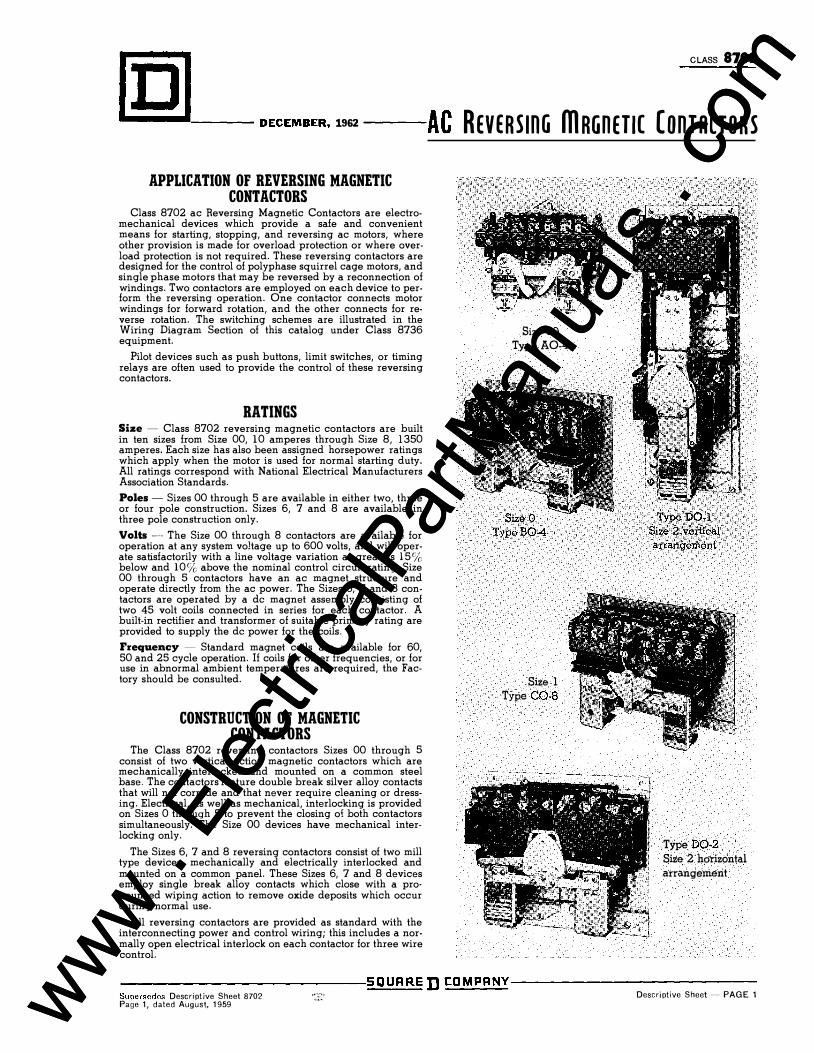
mechanical devices which provide a safe and convenient means for starting, stopping, and reversing ac motors, where other provision is made for overload protection or where overload protection is not required. These reversing contactors are designed for the control of polyphase squirrel cage motors, and single phase motors that may be reversed by a reconnection of windings. Two contactors are employed on each device to perform the reversing operation. One contactor connects motor windings for forward rotation, and the other connects for reverse rotation. The switching schemes are illustrated in the Wiring Diagram Section of this catalog under Class 8736 equipment.
Pilot devices such as push buttons, limit switches, or timing relays are often used to provide the control of these reversing contactors.
RATINGS Size - Class 8702 reversing magnetic contactors are built in ten sizes from Size 00, 10 amperes through Size 8, 1350 amperes. Each size has also been assigned horsepower ratings which apply when the motor is used for normal starting duty. All ratings correspond with National Electrical Manufacturers Association Standards.
Poles - Sizes 00 through 5 are available in either two, three or four pole construction. Sizes 6, 7 and 8 are available in three pole construction only.
Volts -·-- The Size 00 through 8 contactors are available for operation at any system voltage up to 600 volts, and will operate satisfactorily with a line voltage variation as great as 15% below and 10% above the nominal control circuit rating. Size 00 through 5 contactors have an ac magnet structure and operate directly from the ac power. The Sizes 6, 7 and 8 contactors are operated by a de magnet assembly consisting of two 45 volt coils connected in series for each contactor. A built-in rectifier and transformer of suitable primary rating are provided to supply the de power for the coils.
Frequency - Standard magnet coils are available for 60, 50 and 25 cycle operation. If coils for other frequencies, or for use in abnormal ambient temperatures are required, the Factory should be consulted.
CONSTRUCTION OF MAGNETIC CONTACTORS
The Class 8702 reversing contactors Sizes 00 through 5 consist of two vertical action magnetic contactors which are mechanically interlocked and mounted on a common steel base. The contactors feature double break silver alloy contacts that will not corrode and that never require cleaning or dressing. Electrical, as well as mechanical, interlocking is provided on Sizes 0 through 5 to prevent the closing of both contactors simultaneously. The Size 00 devices have mechanical interlocking only.
The Sizes 6, 7 and 8 reversing contactors consist of two mill type devices, mechanically and electrically interlocked and mounted on a common panel. These Sizes 6, 7 and 8 devices employ single break alloy contacts which close with a pronounced wiping action to remove oxide deposits which occur during normal use.
All reversing contactors are provided as standard with the interconnecting power and control wiring; this includes a normally open electrical interlock on each contactor for three wire control.
Size 00 Type A0-4
Size 0 TypeB0·4
Size l Type C0-8
Type DO-l Size 2 v�rlical arrangeniemt
Type D0-2 Size 2 horizontal arrangement
�--------------------------:S�Q�U�R�R=E DCDMPRNY----------------------------
Supersedes Descriptive Sheet 8702 ··:�:· Descriptive Sheet-·- PAGE 1 Page 1, dated August, 1959 www .
Elec
tricalP
artM
anua
ls . c
om
www . El
ectric
alPar
tMan
uals
. com
8702 CLASS
rnl
AC REVERSinG ffiRGnETIC ConTRCTORs-- DECEMBER, 1962--�
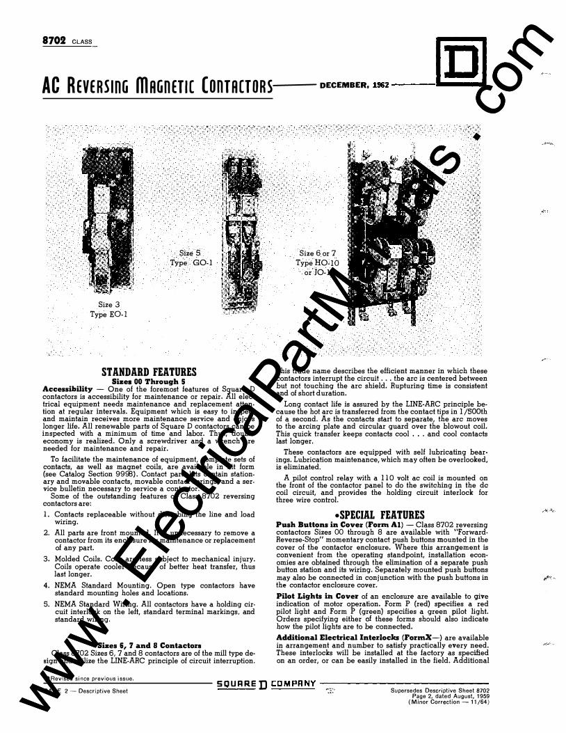
Size 3 Type EO-I
Size 5 Type G0-1
STANDARD FEATURES Sizes 00 Thl'ough 5
Accessibility - One of the foremost features of Square D con!actors is accessibility for maintenance or repair. All elec· !rica! equipment needs maintenance and replacement atten· lion at regular intervals. Equipment which is easy to inspect and maintain receives more maintenance service and enjoys longer life. All renewable parts of Square D contactors can be inspected with a minimum of time and labor. Thus, double economy is realized. Only a screwdriver and a wrench are needed for maintenance and repair.
To facilitate the maintenance of equipment, complete sets of contacts, as well as magnet coils, are available in kit form (see Catalog Section 9998). Contact parts kits contain stationary and movable contacts, movable contact springs, and a ser· vice bulletin necessary to service a contactor.
Some of the outstanding features of Class 8702 reversing contactors are:
1. Contacts replaceable without disturbing the line and load wiring.
2. All parts are front mounted. It is unnecessary to remove a contactor from its enclosure for maintenance or replacement of any part.
3. Molded Coils. Coils are less subject to mechanical injury. Coils operate cooler because of better heat transfer, thus last longer.
4. NEMA Standard Mounting. Open type con!ac!ors have standard mounting holes and locations.
5. NEMA Standard Wiring. All contactors have a holding cir· cui! interlock on the left, standard terminal markings, and standard wiring.
Sizes 6, 7 and 8 Contactoi'S Class 8702 Sizes 6, 7 and 8 con!ac!ors are of the mill type de·
sign and utilize the LINE-ARC principle of circuit interruption.
Size 6or 7 TypeH0-10
or J0-1
This trade name describes the efficient manner in which these con factors interrupt the circuit ... the arc is centered between but not touching the arc shield. Rupturing time is consistent and of short d ura!ion.
Long contact life is assured by the LINE-ARC principle because the hot arc is transferred from the contact tips in 1 /SOOth of a second. As the contacts start to separate, the arc moves to the arcing plate and circular guard over the blowout coil. This quick transfer keeps contacts cool ... and cool contacts last longer.
These con!ac!ors are equipped with self lubricating bearings. Lubrication maintenance, which may often be overlooked, is eliminated.
A pilot control relay with a 110 volt ac coil is mounted on the front of the con!ac!or panel to do the switching in the de coil circuit, and provides the holding circuit interlock for three wire control.
•SPECIAL FEATURES Push Buttons in Covel' (Fol'm AI) - Class 8702 reversing con!ac!ors Sizes 00 through 8 are available with "ForwardReverse-Stop" momentary contact push buttons mounted in the cover of the con!ac!or enclosure. Where this arrangement is convenient from the operating standpoint, installation economies are obtained through the elimination of a separate push button station and its wiring. Separately mounted push buttons may also be connected in conjunction with the push buttons in the con!ac!or enclosure cover.
Pilot Lights in Covel' of an enclosure are available to give indication of motor operation. Form P (red) specifies a red pilot light and Form P (green) specifies a green pilot light. Orders specifying either of these forms should also indicate how the pilot lights are to be connected.
Additional Electdcallntedocks (Fol'mX-) are available in arrangement and number to satisfy practically every need. These interlocks will be installed at the factory as specified on an order, or can be easily installed in the field. Additional
•Revised since previous issue.
PAGE 2- Descriptive Sheet SQUARED COMPANY--------------
�:::, Supersedes Descriptive Sheet 8702 Page 2, dated August, 1959
(Minor Correction -11/64) www . El
ectric
alPar
tMan
uals
. com
www . El
ectric
alPar
tMan
uals
. com
CLASS 8702
� -- AUGUST, 1959 -- A. c. REVERSinG ffinGnETIC ConrncroRs
interlocks cannot be added to the Size 00 contactors. Inter· locks for installation by users are listed in Catalog Section Class9999 .
Low Voltage Control Circuits may be used to provide addi· tiona! safety for personnel by allowing operation of control circuits and magnet coils at a low voltage. This feature is avail· able in two ways:
a. Separate Control (Form S) - The control circuit may be wired for connection to a separate power source. With this arrangement it is possible to operate the control circuit at a different voltage and/or frequency than that required for motor operation.
b. Fused Control Circuit Transformer (Form FT) - A control circuit transformer may be used to provide a 1 10 volt operating voltage for the control circuit. Usually one side of the transformer has a provision for grounding when conditions permit. Short circuit protection for the trans· former and control circuit is provided by a fuse adjacent to the transformer and in the secondary circuit. The fuse is placed on the ungrounded side of the transformer.
GENERAL PURPOSE AND SPECIAL PROTECTIVE ENCLOSURES
The correct selection of an enclosure for a particular appli· cation can contribute considerably to the length of life and trouble free operation of a contactor. In order to shield electrically live parts from accidental contact, some form of enclosure is always necessary. This function is usually fulfilled by a general purpose, sheet steel cabinet. Frequently, dust, moisture or explosive gases make it necessary to employ a special enclosure to protect the contactor from corrosion or the surrounding equipment from explosion. In selecting control apparatus, it is always necessary to carefully consider the conditions under which the apparatus must operate, as there are many applications where a general purpose sheet steel enclosure does not afford sufficient protection.
Watertight and dust-tight enclosures are used for the protection of control apparatus. Dirt, oil, or excessive moisture are destructive to insulation, and frequently form current carrying paths which lead to short circuits or grounded circuits. The extra cost of special enclosures is soon repaid by the reduced cost of maintenance and freedom from unnecessary shutdowns.
Special enclosures for hazardous locations are for the protection of life and property. Explosive vapors or dusts exist in some locations of many industrial plants, as well as in grain elevators and chemical plants. Article 500 of The National Electrical Code describes hazardous locations, and the Underwriters' Laboratories have defined the requirements for proective enclosures according to the hazardous conditions.
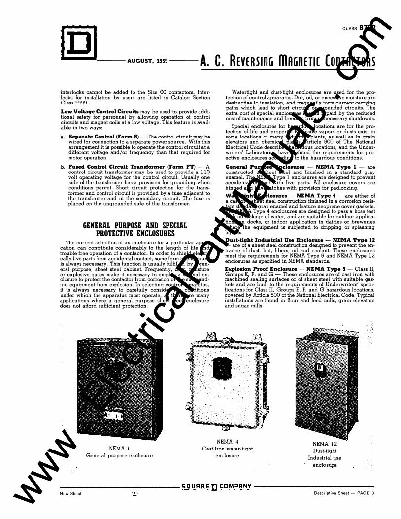
General Purpose Enclosures - NEMA Type 1 - are constructed of sheet steel and finished in a standard gray enamel. The NEMA Type 1 enclosures are designed to prevent accidental contact with live parts. All enclosure covers are hinged and have latches with provision for padlocking.
Watertight Enclosures - NEMA Type 4 - are either of a cast or a sheet steel construction finished in a corrosion resistant standard gray enamel and feature neoprene cover gaskets. The NEMA Type 4 enclosures are designed to pass a hose test with no leakage of water, and are suitable for outdoor applications on docks, or indoor application in dairies or breweries where the equipment is subjected to dripping or splashing liquids.
Dust-tight Industrial Use Enclosure - NEMA Type IZ - are of a sheet steel construction designed to prevent the entrance of dust, lint, fibers, oil and coolant. These enclosures meet the requirements for NEMA Type 5 and NEMA Type 12 enclosures as specified in NEMA standards.
Explosion Proof Enclosure - NEMA Type 9 - Class II, Groups E, F, and G - These enclosures are of cast iron with machined sealing surfaces or of sheet steel with suitable gaskets and are built to the requirements of Underwriters' specifications for Class II, Groups E, F, and G hazardous locations, covered by Article 500 of the National Electrical Code. Typical installations are found in flour and feed mills, grain elevators and sugar mills.
NEMA 4
NEMA 1 General purpose enclosure
Cast iron water-tight
enclosure
NEMA 12 Dust-tight
Industrial use
enclosure
-------------- SQUARED CDMPANY --------------New Sheet Descriptive Sheet- PAGE 3 www .
Elec
tricalP
artM
anua
ls . c
om
www . El
ectric
alPar
tMan
uals
. com
APRIL, 1956 Supersedes Dimension Sheet 8702, Page 2, dated August, 1950
CLASS 8702 Dimension Sheet PAGE 1
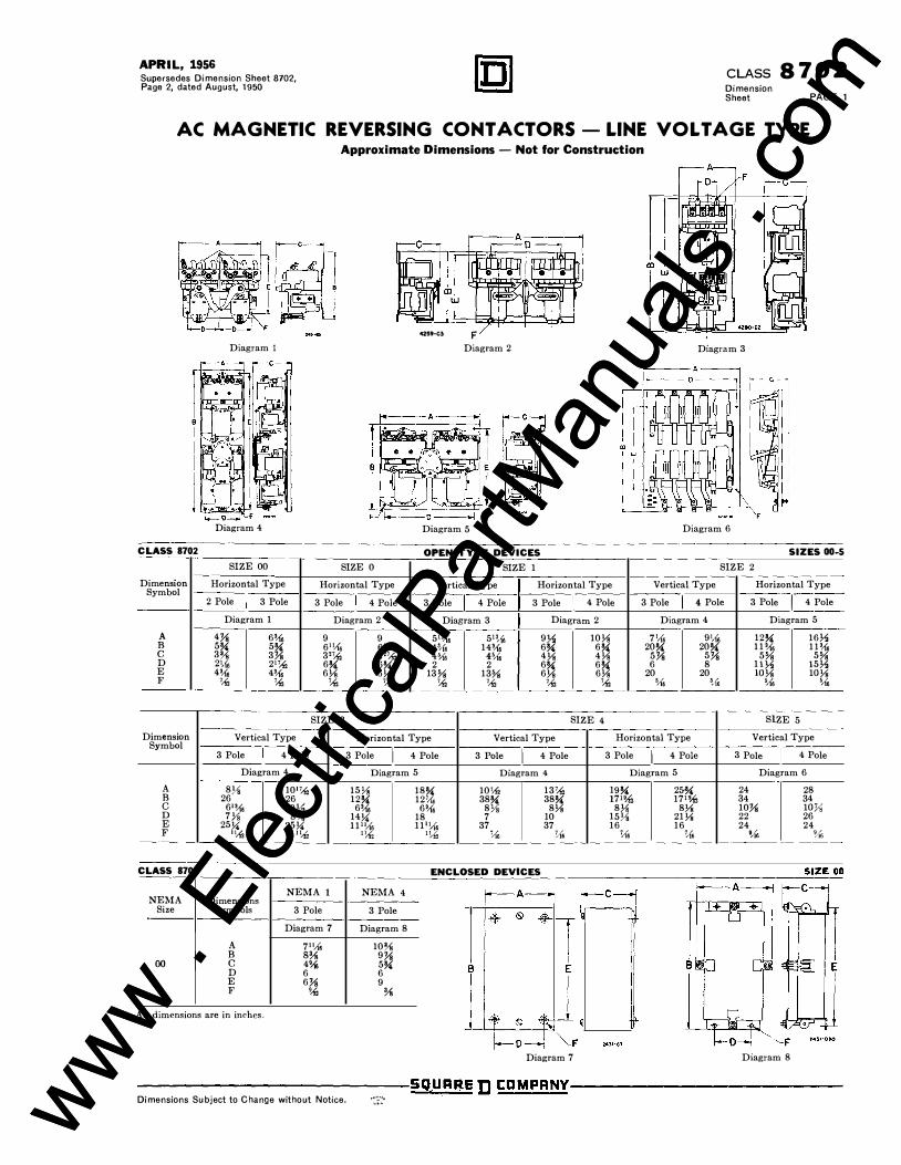
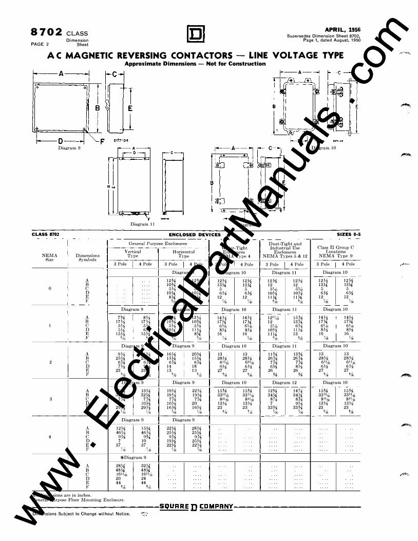
AC MAGNETIC REVERSING CONT ACTORS - LINE VOLT AGE TYPE Approximate Dimensions - Not for Construction
Diagram 1
Diagram 4
CLASS 8702
SIZE 00 SIZE 0
Dimension Horizontal Type Horizontal Type Symbol
I I 2 Pole 3 Pole 3 Pole 4 Pole
Diagram 1 Diagram 2
A 4� 6% 9 9 B 5� 5� 6",1, 6".1' c 3% 3� 3'� 3'� D 21,{, 2'� 6� 6� E 4% 4% 6Ys 6Ys F ,, � � ,,
SIZE 3
42!59-C3 F Diagram 2
Diagram 5
OPEN TYPE DEVICES SIZE 1
Vertical Type Horizontal Type
3 Pole I 4 Pole 3 Pole I 4 Pole
Diagram 3 Diagram 2
5'% 5".1• 9)/o 10Ys 14',(, 14% 6� 6�
41),{, 4% 4Ys 4Ys 2 2 6� 6�
13% 13% 6Ys 6Ys � ,, ,, �
SIZE 4
Diagram 3
Diagram 6
SIZES 00-5
SIZE 2
Vertical Type Horizontal Type
3 Pole I 4 Pole 3 Pole I 4 Pole-
Diagram 4 Diagram 5
7',1, 9',1, 12� 16Y. 20� 20� 11% 11%
5� 5� 5% 5% 6 8 11)/o 15Y.
20 20 lOYs lOYs % 5/(6 '.16 %
SlZE 5
Dimension Vertical Type Horizontal Type Vertical Type Horizontal Type Vertical Type Symbol
3 Pole I 4 Pole 3 Pole I 4 Pole 3 Pole I 4 Pole 3 Pole I 4 Pole 3 Pole I 4 Pole
Diagram 4 Diagram 5 Diagram 4 Diagram 5 Diagram 6
A 8Ys 101� 15Ys 18� 10'"' 13� 19� 2&� 24 28 B 26 26 12� 121,{, 38� 38� 17".-12 17".-12 34 34 c 6'% 9)/o 6% 6% 8Ys 8Ys 8Ys 8Ys 10� lOY, D 7Ys 8% 14� 18 7 10 15Ys 21Ys 22 26 E 25� 25� 11",1, 11'\1, 37 37 16 16 24 24 F ""' I� ��2 l�f ',{, % % l,j', 9,(6 'U6
CLASS 8702 ENCLOSED DEVICES
NEMA 1 NEMA 4 NEMA Dimensions
Size Symbols 3 Pole 3 Pole ·----
Diagram 7 Diagram 8
A 7",{, 10% B s:v. 9� 00 c 4% 5� I
D 6 6 B E E 6� 9 F % :v.
All dimensions are in inches.
Diagram 7 Diagram 8
--------------5QUAI{E D I:DMPANY--------------Dimensions Subject to Change without Notice. ·:�·:· www .
Elec
tricalP
artM
anua
ls . c
om
www . El
ectric
alPar
tMan
uals
. com
8 702 CLASS Dimension
PAGE 2 Sheet
APRIL, 1956 Supersedes Dimension Sheet 8702,
Page 1, dated August, 1950
A C MAGNETIC REVERSING CONT ACTORS LINE VOLT AGE TYPE Approximate Dimensions - Not for Construction
+
D Diagram 9
m..,
CLASS 8702
-A__. r01
\. F Diagram 11
i-o--i Diagram 12
ENCLOSED DEVICES
General Purpose Enclosures
Vertical NEMA Dimensions Type
Size Symbols 3 Pole ! 4 Pole
A B
0 c D E F
Diagram 9
A 7% 8% B 17% 17% I c 5% 5%
D 5U 6� E 15� 15}2 F % �{z Diagram 9
A 9% II% B 25Ys 25Ys 2 c 6% 6%
D 7� g� E 23 23 F % 9/a2
Diagram 9
A 10% 13Ys B 32Ys 32Ys 3 c 7% 7%
D 8 lOY, E 29� 29� F �-(r) 7/(fJ
Diagram 9
A 12Ys !.5Ys B 46% 46% 4 c 9% ()'ji
D 7 10 E 37 37 F �w � (6
*Diagram 9
A 28!4 32!4 B 48!4 48!4
.5 c 1611i/(6 16'"'1, D 20 24 E 44 44 F �iG 9/i{;
All dimensions are in inches. General Purpose Floor Mounting Enclosure.
Horizontal Type
3 Pole I 4 Pole
Diagram n 12% 12% 10% 10%
5% 5% 10!4 10!4
8!4 8!4 �2 �32 Diagram 9
12% 13�� 10% 10%
5% 5% 10!4 ]]�
8!4 8!4 �{� �;{2 Diagram 9
16Ys 20Ys 15Ys 15Ys
6% 6% 14 18 13 1:3
% � Diagram 9
19Ys 22% 19Ys 19Ys
7'!1i 7% Hl� 20 16� 16�
�6 1/J'n Diagram 9
22Ys 28Ys 2.0Ys 25Ys
9% 9% 19� 20� 22Y, 22Yz � �6
Water-Tight Enclosures
NEI\IA Type 4
3 Pole I 4 Pole
Diagram 10
12� 12� 13!4 13!4
5 5 6� 6�
12 12 % �6
Diagram 10
14� 14� 17!4 17!4 (iS/if, 65/]"6
8� 8� 16 16
�J6 �6
Diagram 10
13 13 28� 28� fil%;
61?16 fj� 6�
27 27 9/{6 9/J6
Diagram 10
15% 331?{6
8"1, 13% 23
9/(6
15% 3311i/(6
81�(6 13% 23
�(o
.. ..
Dust-Tight and Industrial Use
Enclosures NEMA Types 5 & 12
3 Pole I 4 Pole
Diagram 11
12� 12� 12 12 .s:l,.f 5%, 10� 10� ll!4 11!4
9/aZ 9/a2
Diagram 11
1217/:li 15% 12 13%
5�2 6% 10� II� 11!4 13
% �{z Diagram 11
11% 13% 26% 26%
7% 7% 6� 8�
26 26 % %
Diagram 12
12% 34!4
8% 7
33% �6
....
14% 34!4
8'!1i 9�
33% �6
... .
..
.. . .
Diagram 10
SIZES 0-5
Class II Group C Locations
NEI\IA Type 9
3 Pole I 4 Pole
Diagram 10
12� 12� 13!4 13!4
5 5 6� 6�
12 12 7,]6 I Yi'6
Diagram 10
14� 14� 17!4 17!4
65/(fi 65/{6 8� 8�
16 16 �{6 �
Diagram 10
13 13 28� 28�
615/(6 615/ili 6� 6�
27 27 U6 9/{6
Diagram 10
15% 331�i6
811/i'6 13% 23
�i6
. ..
15% 331%
811:16 13% 23
�·16
..
----------------------------SOURRE D CDMPRNY----------------------------Dimensions Subject to Change without Notice. www .
Elec
tricalP
artM
anua
ls . c
om
www . El
ectric
alPar
tMan
uals
. com
SUPERSEDES: Class 8702 Page 101 December, 1966
CLASS 8 7 02 PAGE 101
SEPTEMBER,1969
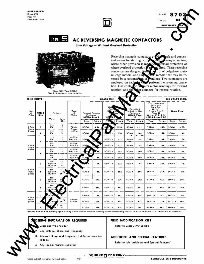
'"''*' AC REVERSING MAGNETIC CONT ACTORS
Line Voltage - Without Overload Protection
Class 8702 Type SC0-8 Size 1, 3 pole reversing contactor
Reversing magnetic contactors provide a safe and convenient means for starting, stopping and reversing ac motors, where other provision is made for overload protection or where overload protection is not required. These reversing contactors are designed for the control of polyphase squirrel cage motors, and single phase motors that may be reversed by a reconnection of windings. Two contactors are employed on each device to perform the reversing operation. One contactor connects motor windings for forward rotation, and the other connects for reverse rotation.
50-60 HERTZ CLASS 8702 600 VOLTS MAX.
For Hazardous Locations
Water-tight Spin Top Enclosure Dust-tight Class I
No. Type (AISI #304 Industrial Use Groups C & D Open Type of NEMA Ratings of General Purpose Stainless Enclosure Class II
Poles Size Motor Enclosure Steel) NEMA Type Groups E, F & G NEMA Type 1 NEMA Type 4 12 NEMA Types 7 &9
Volts Max. Hp. Type Price* Type Price* Type Price* Type Price* Type Price*
---- --- --- --- ---
115 1 2 Pole 0 230 2 Single SBG-1 $ 74. SBW-11 $120. SBA-1 $ 92. SBR-6 $235. SB0-1 $ 70. Single ---- ----- ---- Phase - ---- -- -- ---- - --- - -- -- ---- ----- ---- -- ----
Phase 115 2 3-Wire 1 230 3 SCG-2 86. SCW-11 150. SCA-1 104. SCR-6 247. SC0-2 so.
--- --- --- --- ---
115 1 4-Wire 230 2 Rep.-lnd. SBG-2 76. SBW-12 122. SBA-2 94. SBR-7 237. SB0-2 72.
0 - --- --- -- --- - ----- --- - -- - - -- - ---- --- ---- --- -
115 1 4-Wire 3 Pole 230 2 Split Ph. SBG-3 76. SBW-13 122. SBA-3 94. SBR-8 237. SB0-3 72. Single ---- -- -- ---- ---- -- --- ----- --- - --- - -- --- -- - -- -- - ---- - -
Phase 115 2 4-Wire 230 3 Rep.-Ind. SCG-4 88. SCW-12 152. SCA-2 106, SCR-7 249. SC0-4 82.
1 ----- --- -- ---- ---- --- --- ---- ----- - -- --- - --
115 2 4-Wire 230 3 Split Ph. SCG-6 88. SCW-13 152. SCA-3 106, SCR-8 249. SC0-6 82.
--- --- --- --- ---
110 2 0 208-220 3 SBG-4 76. SBW-14 122. SBA-4 94. SBR-9 237. SB0-4 72.
440-550 5 - - - --- - - ---- - --- - -- - ----- - -- - --- --- ---
3 Pole 110 3 Poly- 1 208-220 7Y, SCG-8 88. SCW-14 152. SCA-4 106. SCR-9 249. SC0-8 82. phase 440-550 10
- -- ---- - -- 3 Phase ----- - -- -- --- - ---- ---- - --- ----- ---- --- ---
110 1Y, 2 208-220 15 SDG-2 172. SDW-11 276. SDA-1 202. SDR-3 415. SD0-2 156.
440-550 25 --- - - --- -- -- - -- -- -- - -- -- -- -- --- -- --- --- - -- --
110 15 3 208-220 30 SEG-2 287. SEW-11 441. SEA-1 353. SER-1 666. SE0-2 259.
440-550 50 --- --- --- --- --- ---
220 3 0 440-550 5 SBG-5 96. SBW-15 142. SBA-5 114. SBR-10 257. SB0-5 92.
4 Pole ---- --- -- --- - -- -- - --- - ----- ---- ---- ---- -- -- - - -- --- - - -
Poly- 220 7Y, 2 Phase phase 1 440-550 10 4-Wire SCG-10 109. SCW-15 173. SCA-5 127. SCR-10 270. SC0-10 105.
-- -- ----- --- ----- ---- --- - ---- ---- --- ---- -- -- --- - --
220 15 2 440-550 25 S DG-4 214. SDW-12 324. SDA-2 244. SDR-4 463. SD0-4 198.
*Prices include one normally open holding circuit contact and one normally closed interlocking contact on each contactor- no deduction for omission.
ORDERING INFORMATION REQUIRED 1-Ciass and type number.
2-Line voltage, phase and frequency.
3-Control voltage and frequency if different from line
voltage.
4-Any special features required.
FIELD MODIFICATION KITS Refer to Class 9999 Section
ADDITIONS AND SPECIAL FEATURES Refer to tab "Additions and Special Features"
---------------------------;S�g�U�A�R�E D tDMPRNY--------------------------
Prices subject to change without notice. scHEDULE DS-1 DISCOUNTS www . El
ectric
alPar
tMan
uals
. com
www . El
ectric
alPar
tMan
uals
. com
SUPERSEDES: Class 8702 Page 103 December, 1966
CLASS 8 702 PAGE 103
SEPTEMBER, 1969
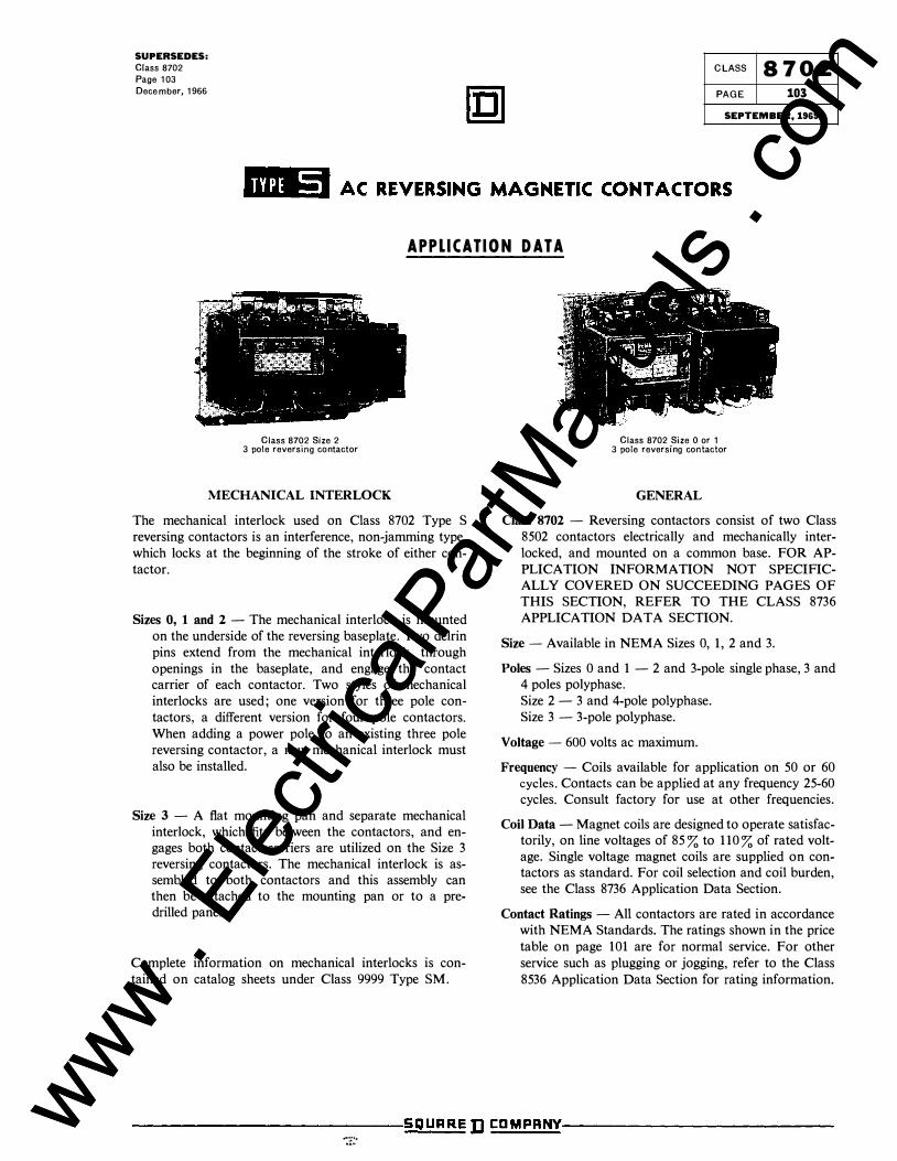
APPLICATION DATA
Class 8702 Size 2 3 pole reversing contactor
MECHANICAL INTERLOCK
The mechanical interlock used on Class 8702 Type S reversing contactors is an interference, non-jamming type, which locks at the beginning of the stroke of either contactor.
Sizes 0, 1 and 2 - The mechanical interlock is mounted on the underside of the reversing baseplate. Two delrin pins extend from the mechanical interlock, through openings in the baseplate, and engage the contact carrier of each contactor. Two styles of mechanical interlocks are used; one version for three pole contactors, a different version for four pole contactors. When adding a power pole to an existing three pole reversing contactor, a new mechanical interlock must also be installed.
Size 3 - A flat mounting pan and separate mechanical interlock, which fits between the contactors, and engages both contact carriers are utilized on the Size 3 reversing contactors. The mechanical interlock is assembled to both contactors and this assembly can then be attached to the mounting pan or to a predrilled panel.
Complete information on mechanical interlocks is contained on catalog sheets under Class 9999 Type SM.
Class 8702 Size 0 or 1 3 pole reversing contactor
GENERAL
Class 8702 - Reversing contactors consist of two Class 8502 contactors electrically and mechanically interlocked, and mounted on a common base. FOR APPLICATION INFORMATION NOT SPECIFICALLY COVERED ON SUCCEEDING PAGES OF THIS SECTION, REFER TO THE CLASS 8736 APPLICATION DATA SECTION.
Size- Available in NEMA Sizes 0, 1, 2 and 3.
Poles - Sizes 0 and 1 - 2 and 3-pole single phase, 3 and 4 poles polyphase. Size 2 - 3 and 4-pole polyphase. Size 3 - 3-pole polyphase.
Voltage - 600 volts ac maximum.
Frequency - Coils available for application on 50 or 60 cycles. Contacts can be applied at any frequency 25-60 cycles. Consult factory for use at other frequencies.
Coil Data - Magnet coils are designed to operate satisfactorily, on line voltages of 85% to 110% of rated voltage. Single voltage magnet coils are supplied on contactors as standard. For coil selection and coil burden, see the Class 8736 Application Data Section.
Contact Ratings - All contactors are rated in accordance with NEMA Standards. The ratings shown in the price
table on page 101 are for normal service. For other service such as plugging or jogging, refer to the Class
8536 Application Data Section for rating information.
--------------------------:S�Q�U�A�R�E D C�D�M�P�AN�Y!-------------------------���T:o www . El
ectric
alPar
tMan
uals
. com
www . El
ectric
alPar
tMan
uals
. com
CLASS 8 702 PAGE 104
SEPTEMBER, 1969
SUPERSEDES: Class 8702
Page 104 December, 1966
id'l#l AC REVERSING MAGNETIC CONTACTORS
APPLICATION DATA
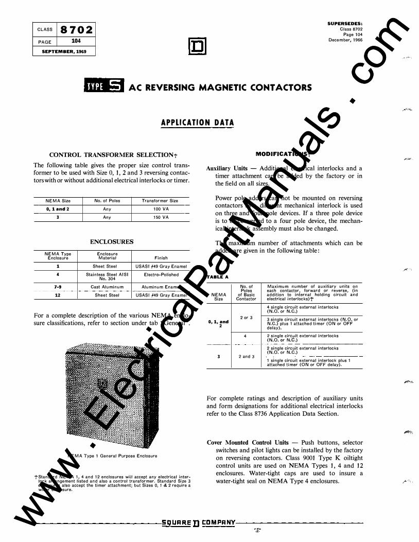
CONTROL TRANSFORMER SELECTION "t The following table gives the proper size control transformer to be used with Size 0, 1, 2 and 3 reversing contactors with or without additional electrical interlocks or timer.
NEMA Size No. of Poles Transformer Size
0, 1 and 2 Any 100 VA
3 Any 150 VA
ENCLOSURES
NEMA Type Enclosure Enclosure Material Finish
1 Sheet Steel USASI #49 Gray Enamel
4 Stainless Steel AISI Electro-Polished No. 304
7-9 Cast Aluminum Aluminum Enamel ---------12 Sheet Steel USASI #49 Gray Enamel
For a complete description of the various NEMA enclosure classifications, refer to section under tab "General".
NEMA Type 1 General Purpose Enclosure
"!"Standard NEMA 1, 4 and 12 enclosures will accept any electrical interlock arrangement listed and also a control transformer. Standard Size 3 enclosures also accept the timer attachment; but Sizes 0, 1 &. 2 require a wider enclosure.
MODIFICATIONS-t
Auxiliary Units - Additional electrical interlocks and a timer attachment can be added by the factory or in the field on all sizes.
Power pole adders can not be mounted on reversing contactors as a different mechanical interlock is used
on three and four pole devices. If a three pole device
is to be converted to a four pole device, the mechanical interlock assembly must also be changed.
The maximum number of attachments which can be added are given in the following table:
TABLE A
No. of Maximum number of auxiliary units on Poles each contactor, forward or reverse, (in
NEMA of Basic addition to internal holding circuit and Size Contactor electrical interlocks)"!"
4 single circuit external interlocks (N.O. or N.C.)
2 or 3 3 single circuit external interlocks (N.O. or 0, 1, and N.C.) plus 1 attached timer (ON or OFF 2 delay).
4 2 single circuit external interlocks (N.O. or N.C.) ----2 single circuit external interlocks (N.O. or N.C.)
3 2 and 3 1 single circuit external interlock plus 1 attached timer (ON or OFF delay).
For complete ratings and description of auxiliary units
and form designations for additional electrical interlocks
refer to the Class 8736 Application Data Section.
Cover Mounted Control Units - Push buttons, selector
switches and pilot lights can be installed by the factory
on reversing contactors. Class 9001 Type K oiltight
control units are used on NEMA Types 1, 4 and 12 enclosures. Water-tight caps are used to insure a
water-tight seal on NEMA Type 4 enclosures.
--------------:S!;O�U!!R�RE D COMPANY-------------
"''''"·
www . El
ectric
alPar
tMan
uals
. com
www . El
ectric
alPar
tMan
uals
. com
SUPERSEDES: Class 8702 Page 105 December, 1966
CLASS 8 702 PAGE 105
SEPTEMBER,1969
ili)i#i AC REVERSING MAGNETIC CONY ACTORS
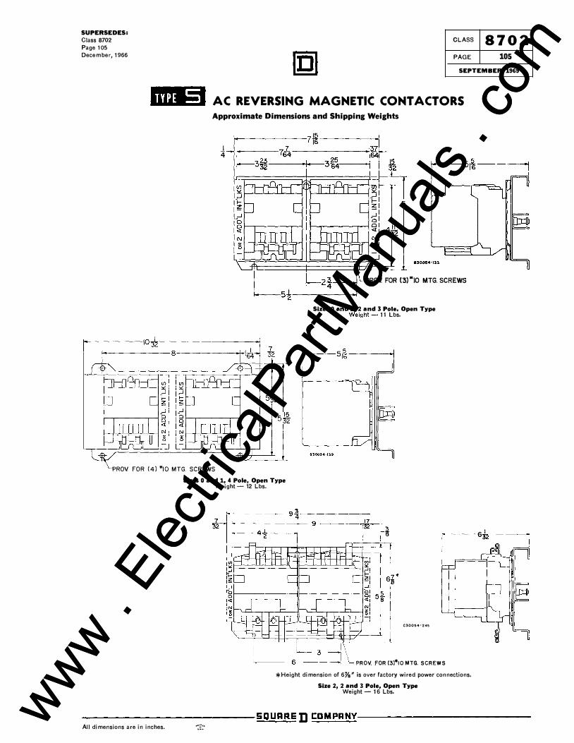
Approximate Dimensions and Shipping Weights
I 4
�����-- IQ�--����������
PROV FOR (4) "10 MTG. SCREWS Sizes 0 and 1, 4 Pole, Open Type
Weight- 12 Lbs.
PROV. FOR (3) •10 MTG. SCREWS
Sizes 0 and.�, 2 and 3 Pole, Open Type weight- 11 Lbs.
C30054� 245
PROV. FOR (3)*10 MTG. SCREWS *Height dimension of 6fs" is over factory wired power connections.
Size 2, 2 and 3 Pole, Open Type Weight- 16 Lbs.
--------------------------SQUARE D �CD�M�P�A�NY!--------------------------All dimensions are in inches. ·:::· www .
Elec
tricalP
artM
anua
ls . c
om
www . El
ectric
alPar
tMan
uals
. com
CLASS 8702 PAGE 106
SEPTEMBER, 1969
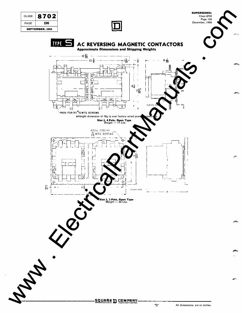
AC REVERSING MAGNETIC CONT ACTORS Approximate Dimensions and Shipping Weights
21 1232 -��---�---� �--��-� 10 i ---::-----===r_fz�L�
�-11 H---JI.--H-.l-l� I
'�PROV. FOR (4) *10 MTG. SCREWS
sl 4 5*
732
*Height dimension of 7%z is over factory wired power connections.
Size �P.4 Pole, Open Type weight- 17 Lbs.
yM 32
I ;
C30054-353A
Size 3, 3 Pole, Open Type Weight- 35 Lbs.
��- -- y�--- -�----
SUPERSEDES: Class 8702
Page 106 December, 1966
--------------------------S�Q�U�A�RE D C�D�M�P�AN�Y!--------------------------All dimensions are in inches. www .
Elec
tricalP
artM
anua
ls . c
om
www . El
ectric
alPar
tMan
uals
. com
SUPERSEDES: Class 8702 Page 107 December, 1966
CLASS 8 702 PAGE 107
SEPTEMBER, 1969
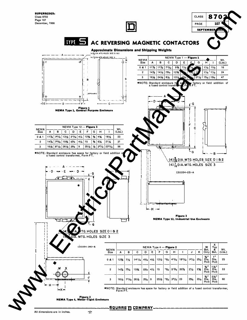
jfbiiij AC REVERSING MAGNETIC CONY ACTORS
Approximate Dimensions and Shipping Weights
1------ A----------< (41 ,\ DIA.MTG.HOLES SIZEO,Ia2 r.:::=========:;;fv----1 (4l�DIA MTG HOLES SIZE 3
4 +
B G
Hlj-:=:=:=:=:=:=:=:=--tHJ .••• 0 '-----t--T+-I __j E /1----- 0 ___ / F � I--- C ---' T
Fl&ure 1 NEMA Type 1, General Purpose Enclosure
NEMA NEMA Type 12- Fl&ure 3
Wt. Size A B c D E F G H I (Lbs.)
--- -- -- -- -- - -- - -- -- ---0 &. 1 11% 7•';1, 13!--2 3'�6 4\4 12% % 4% 18Vs 23
--- -- -- -- -- - -- - -- -- ---2 14% 7'�' 15% 5o/.6 4V4 15 % 6\4 21Y., 31
--- -- -- -- -- - -- - -- -- ---3 16!41 a• ';I, 26!--2 3'!46 9 25!--2 !--2 3•';), 23'% 56
•NOTE: Standard enclosure has space for factory or field addition of a fused control transformer, Form FT.
I
A
FJ • � o -rG
[B
J.. � •
F C
•
'[ r1 � LG I I I I \ DIA. MTG. HOLES I I SIZE 0 I a 2
(4)fsDIA. MTG. HOLES SIZE 3
H
\ C30054-260-A NEMA
Size ---
0 &. 1 ----
2 ---
3
A --
12% --
14% --
16Vs
B --
7Vs --
7% --
71�6
NEMA NEMA Type 1 - Fl&ure 1
Wt. Size A B c D E F G H I (Lbs.)
--- -- -- -- -- -- -- -- -- -- ---0&.1 11% 11% 7'�' 9% 1 Yl6 1Y16 9% 1Y16 1 Yl6 16
--- -- -- -- -- -- -- -- -- -- ---2 14% 14Vs 7'!46 12% 1V.6 1 Yl6 12 1 Yl6 1 Yl6 24 --- -- -- -- -- -- -- -- -- -- ---3 16!.-8 24Ya 8!--2 13Va 1¥16 1o/,6 21!--2 1¥16 1o/.6 47
•NOTE: Standard enclosure has space for factory or field addition of a fused control transformer, Form FT.
G
� F C
B__j
I I I I I I I I I I I I I I
(4lts DIA. MTG. HOLES SIZE 0 I a 2 (4l {s DI A.MTG.HOLES SIZE3
I I I I I I I
I I -H _j I
C30054-251-A
IH
Fl&ure 3 NEMA Type 12, Industrial Use Enclosure
c --
141 Yl6 --
1 5% --
26!1:!
NEMA Type 4- Fl&ure 2 D E F G H
-- -- -- -- --
4�6 4!4 13!--2 '%• 41�6 -- - -- - --
5o/16 4!4 15 '%• 5'o/.6 -- - -- - --
3% 9 25!1:! '% 3'';1'
w Bot.
I J K Only -- -- -- --
18'% 1•';), 2% 61" a. Hub
--- -- -- --
20% 2';), 2% 61:. Hub
-- -- -- --
23 2'!46 3�6 61" a. Hub
X Top &. Wt. Bot. (Lbs.)
-- --1"
Dia. 25 Hub
-- --1 Y2" Dia. 33 Hub
-- --2!1:!" Dia. 60 Hub
•NOTE: Standard enclosure has space for factory or field addition of a fused control transformer, Form FT.
Fl&ure 2 NEMA Type 4, Water-Tight Enclosure
----------------------------SQURRE D CDMPRNY----------------------------All dimensions are in inches. www .
Elec
tricalP
artM
anua
ls . c
om
www . El
ectric
alPar
tMan
uals
. com
CLASS 8 702 PAGE 108
SEPTEMBER, 1969
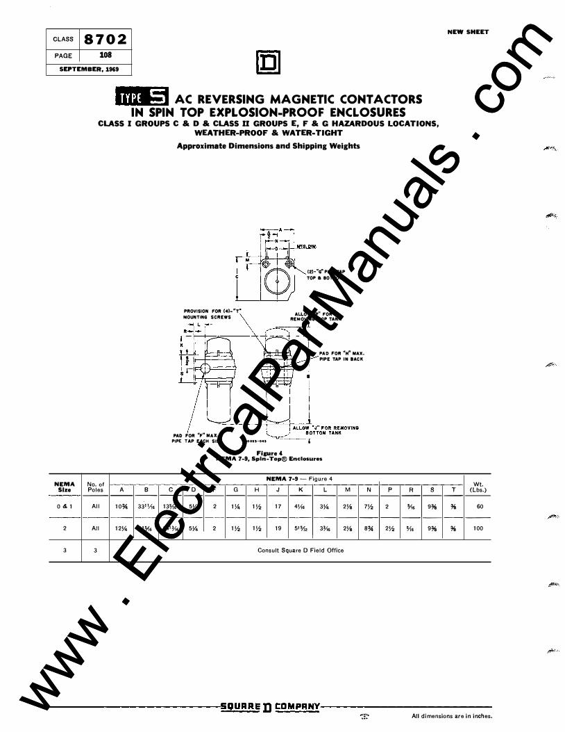
-.::1 AC REVERSING MAGNETIC CONTACTORS
IN SPIN TOP EXPLOSION-PROOF ENCLOSURES CLASS I GROUPS CaD a CLASS II GROUPS E, FaG HAZARDOUS LOCATIONS,
WEATHER-PROOF a WATER-TIGHT
NEMA No. of Size Poles A B
--- -- --
0&1 All 10% 33'Yt•
-- ---
2 All 12V.. 41'i1.
3 3
Approximate Dimensions and Shipping Weights
PROVISION FOR (4)-"T• MOUNTING SCREWS
�
PAD FOR 11F" MAX. PIPE TAP EACH SlOE • �005�-041
Figure 4
(2)-"G" P I PE TAP TOP a BOTTOM
ALLOW "P11 FOR REMOVING TOP TANK
PAD FOR ''H" MAX. PIPE TAP I N BACK
NEMA 7-9, Spin-Top® Enclosures
NEMA 7-9 - Figure 4
c D F G H J K L M N -- -- -- -- -- -- -- -- -- --
13'Vt. 5V.. 2 1V.. 1� 17 4Yt. 3V.. 2Ys 7�
-- -- -- -- -- -- --- -- -- --
14'% 5V.. 2 1� 1� 19 5'% 3Y,• 2Ys 8%
Consult Square D Field Office
p R s -- -- --
2 o/t• 9% -- -- --
2� 'Vt. 9%
NEW SHEET
Wt. T (lbs.) -- ---
% 60
-- ---
% 100
-------------�S!_Q§t!!U!!A�RE D CDMPANY-------------
-:::· All dimensions are in inches. www . El
ectric
alPar
tMan
uals
. com
www . El
ectric
alPar
tMan
uals
. com


![Reversing and Malware Analysis Training Articles [2012] . cracking/Reversing... · Reversing and Malware Analysis Training Articles ... Step 1: Start with what you ... Reversing and](https://img.pdfslide.us/doc/110x75/5ab905fd7f8b9ac10d8db0ab/reversing-and-malware-analysis-training-articles-2012-crackingreversingreversing.jpg)