Embed Size (px)
Citation preview

© 1996-2009 Operation Technology, Inc. – Workshop Notes: AC Network
AC Network

© 1996-2009 Operation Technology, Inc. - Workshop Notes: AC Network
Slide 2
ETAP Overview
• One-Line Diagram
• Toolbar Format
• Dumpster
• Project View
• Project Toolbar
• Mode Toolbar
• System Toolbar
• Study Case Toolbar
• Message Log

© 1996-2009 Operation Technology, Inc. - Workshop Notes: AC Network
Slide 3
One-Line Diagram
In Edit Mode
Edit Toolbar
AC Elements
DC Elements
Instrument
Devices
System
Toolbar
Select Mode
Edit Mode: Drag/Drop &
Connect Elements
Study Mode: Load Flow,
Short-Circuit, … etc.
Project View
Message Logger
View the latest
messages related to
ETAP Projects.
It can be expanded
or reduced.
Help Line
Displays the
description for
every entry field.

© 1996-2009 Operation Technology, Inc. - Workshop Notes: AC Network
Slide 4
Mode Toolbar Format

© 1996-2009 Operation Technology, Inc. - Workshop Notes: AC Network
Slide 5
Analysis Toolbar Format
1. Run the Calculation
2. Display Options
3. Display Alerts
4. View the Generated Reports
5. Stop the Calculation
6. Get On-Line Data
7. Get Archived Data
Analysis toolbars have the following sections:
All ETAP analysis toolbars follow this general format.
© 1996-2009 Operation Technology, Inc. - Workshop Notes: AC Network
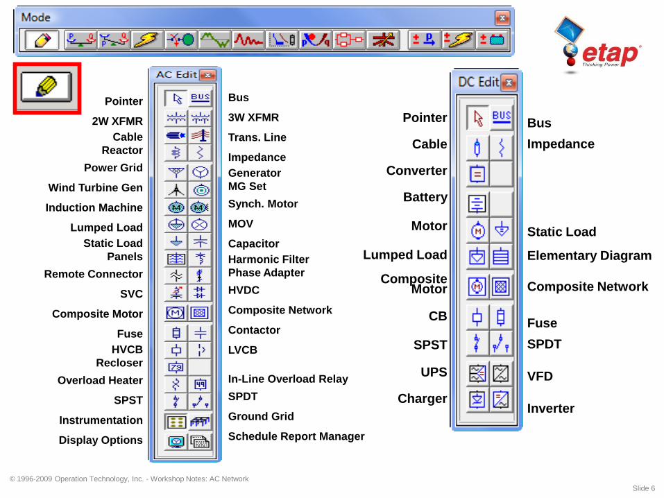
Slide 6
Pointer
2W XFMR
Cable
Reactor
Power Grid
Wind Turbine Gen
Induction Machine
Lumped Load
Static Load
Panels
Remote Connector
SVC
Composite Motor
Fuse
HVCB
Recloser
Overload Heater
SPST
Instrumentation
Display Options
Bus
3W XFMR
Trans. Line
Impedance
Generator
MG Set
Synch. Motor
MOV
Capacitor
Harmonic Filter
Phase Adapter
HVDC
Composite Network
Contactor
LVCB
In-Line Overload Relay
SPDT
Ground Grid
Schedule Report Manager
Pointer
Cable
Converter
Battery
Motor
Lumped Load
Composite Motor
CB
SPST
UPS
Charger
Bus
Impedance
Static Load
Elementary Diagram
Composite Network
Fuse
SPDT
VFD
Inverter

© 1996-2009 Operation Technology, Inc. - Workshop Notes: AC Network
Slide 7
Current Transformer
Voltmeter
Multimeter
Voltage Relay 27 / 59
Frequency Relay 81
Motor Relay
Overload Heater
Taglink
Potential Transformer
Ammeter
Reverse Power Relay
Solid State Trip Relay
Overcurrent Relay 50/51/67
Multi Function Relay

© 1996-2009 Operation Technology, Inc. - Workshop Notes: AC Network
Slide 8
Run Load Flow Calculation
RCAS
Display Options
Load Flow Alerts
Load Flow Report Manager
Stop Calculation
Get On-Line Data
Load Flow Comparator
Get Archived Data
Load Flow Result Analyzer

© 1996-2009 Operation Technology, Inc. - Workshop Notes: AC Network
Slide 9
Run Unbalanced Load Flow
Display Options
Load Flow Alerts
Load Flow Report Manager
Stop Calculation
Get On-Line Data
Load Flow Comparator
Get Archived Data

© 1996-2009 Operation Technology, Inc. - Workshop Notes: AC Network
Slide 10
3-Phase SC Duty Calculation
1-Phase SC Duty Calculation
½ Cycle Unbalanced LG, LL, LLG & 3-Phase
½ to 4 Cycle Unbalanced LG, LL, LLG & 3-Phase
30 Cycle Unbalanced LG, LL, LLG & 3-Phase
Arc Flash Analysis (NFPA 70E & IEEE 1584)
Short-Circuit Display Options
Short-Circuit Alerts for Buses & PDs
Short-Circuit Report Manager
Stop Calculation
Get On-Line Data
Get Archived Data
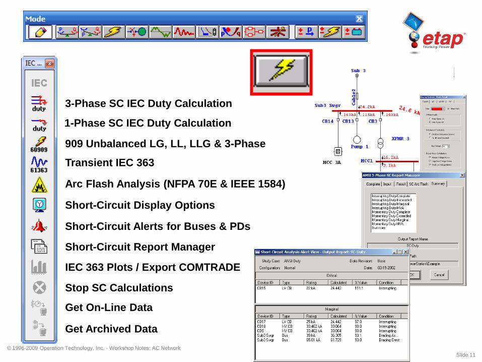
© 1996-2009 Operation Technology, Inc. - Workshop Notes: AC Network
Slide 11
3-Phase SC IEC Duty Calculation
909 Unbalanced LG, LL, LLG & 3-Phase
Transient IEC 363
Arc Flash Analysis (NFPA 70E & IEEE 1584)
Short-Circuit Display Options
Short-Circuit Alerts for Buses & PDs
Short-Circuit Report Manager
Stop SC Calculations
Get On-Line Data
Get Archived Data
IEC 363 Plots / Export COMTRADE
1-Phase SC IEC Duty Calculation

© 1996-2009 Operation Technology, Inc. - Workshop Notes: AC Network
Slide 12
Run Dynamic Motor Acceleration
Run Static Motor Starting
Motor Starting Display Options
Stop Motor Starting Calculation
Get On-Line Data
Get Archived Data
Motor Starting Report Manager
Motor Starting Plot Options
Motor Starting Alerts

© 1996-2009 Operation Technology, Inc. - Workshop Notes: AC Network
Slide 13
Run Harmonic Load Flow Calculation
Run Frequency Scan
Harmonic Analysis Display Options
Stop HA Calculation
Get On-Line Data
Get Archived Data
Harmonic Analysis Plots
Harmonic Analysis Report Manager
Harmonic Analysis Alerts

© 1996-2009 Operation Technology, Inc. - Workshop Notes: AC Network
Slide 14
Run Transient Stability Calculation
TS Display Options
TS Report Manager
Get On-Line Data
Get Archived Data
Stop TS Calculation
Transient Stability Plots
TS Alerts (Future)
TS Action List

© 1996-2009 Operation Technology, Inc. - Workshop Notes: AC Network
Slide 15
Create STAR View
Run / Update SC Clipping kA
Sequence of Operation
Report Manager
Device Settings Report
Display Options
Stop Calculation
Sequence Viewer
Append to STAR View

© 1996-2009 Operation Technology, Inc. - Workshop Notes: AC Network
Slide 16
Run Optimal Power Flow
OPF Display Options
OPF Report Manager
Stop OPF Calculation
Get On-Line Data
Get Archived Data

© 1996-2009 Operation Technology, Inc. - Workshop Notes: AC Network
Slide 17
Run Reliability Assessment Calculation
RA Display Options
RA Report Manager
RA Plots
Get On-Line Data
Get Archived Data
Stop RA Calculation

© 1996-2009 Operation Technology, Inc. - Workshop Notes: AC Network
Slide 18
Run Optimal Capacitor Placement
OCP Display Options
OCP Alerts
OCP Report Manager
Get On-Line Data
Get Archived Data
Stop OCP Calculation
OCP Plots

© 1996-2009 Operation Technology, Inc. - Workshop Notes: AC Network
Slide 19
Run DC Load Flow Calculation
DCLF Display Options
DCLF Report Manager
Get On-Line Data
Get Archived Data
Stop DCLF Calculation

© 1996-2009 Operation Technology, Inc. - Workshop Notes: AC Network
Slide 20
Run DC Short-Circuit Calculation
DCSC Display Options
DCSC Report Manager
Get On-Line Data
Get Archived Data
Stop DCSC Calculation
© 1996-2009 Operation Technology, Inc. - Workshop Notes: AC Network
Slide 21
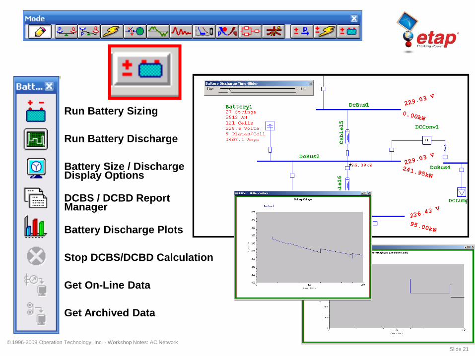
Run Battery Sizing
Run Battery Discharge
Battery Size / Discharge Display Options
Get On-Line Data
Get Archived Data
Stop DCBS/DCBD Calculation
DCBS / DCBD Report Manager
Battery Discharge Plots

© 1996-2009 Operation Technology, Inc. - Workshop Notes: AC Network
Slide 22
Create a New Presentation

© 1996-2009 Operation Technology, Inc. - Workshop Notes: AC Network
Slide 23
Add Elements
Bus ID = (Default ID) + (A Unique Number) = Bus + 1 = Bus1

© 1996-2009 Operation Technology, Inc. - Workshop Notes: AC Network
Slide 24
Connect Element - Bus
• Place the cursor over the pin of an element (pin
appears in red).
• Drag an element and place its pin on a bus.
• Drop a new element with its pin on top of a bus.
• Buses are considered to be one long pin.
Connections are always made from elements to
buses.
• Relays cannot be connected to buses.
• Only one pin of an element can be connected to
the same bus.

© 1996-2009 Operation Technology, Inc. - Workshop Notes: AC Network
Slide 25
Connect Element - Element
• Place the cursor on the pin of an element. Click
and drag the mouse to the element you want to
connect. When the latter element’s pin turns red,
release the left button.
• Drag & drop a protective device with its pin placed
on top of the pin of any branch or load element.
• Drag & drop a protective device onto a connection.
• Branches CANNOT be connected to each other;
PowerStation automatically inserts a bus between
them.

© 1996-2009 Operation Technology, Inc. - Workshop Notes: AC Network
Slide 26
Connect Element - Element
• Branches CANNOT be connected to each other;
PowerStation automatically inserts a bus between
them.
• Branches CANNOT be connected to loads, utilities,
composite motors, and composite networks.
• Relays can only be connected to current
transformers (CT) or other relays.
• You CANNOT directly connect two buses with a
connector or current transformer.

© 1996-2009 Operation Technology, Inc. - Workshop Notes: AC Network
Slide 27
Connect Element - Element
© 1996-2009 Operation Technology, Inc. - Workshop Notes: AC Network
Slide 28
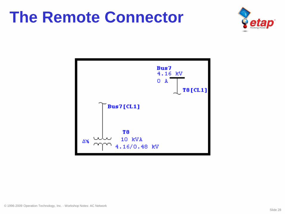
The Remote Connector

© 1996-2009 Operation Technology, Inc. - Workshop Notes: AC Network
Slide 29
Insert Protective Devices
Example
A Circuit Breaker and Fuse are Inserted Between Bus1 and T1.

© 1996-2009 Operation Technology, Inc. - Workshop Notes: AC Network
Slide 30
Move From Dumpster
• Elements can be moved from the Dumpster
into the one-line diagram with the same IDs
by two methods:
– Right-click on the one-line diagram and select
Move From
– Click on Edit on the Menu Bar and select Move
From

© 1996-2009 Operation Technology, Inc. - Workshop Notes: AC Network
Slide 31
Move From Dumpster
• Rules:
– Move From Dumpster can be done only in Edit mode when Base Data is active.
– Move CANNOT be done if there are no Cells (element groups) in the Dumpster.
– When you move a Dumpster Cell to the one-line diagram, the desired cell needs to be active and it gets deleted from the Dumpster after being moved.

© 1996-2009 Operation Technology, Inc. - Workshop Notes: AC Network
Slide 32
Move From Dumpster
• Move any Dumpster Cell you desire by making it
active from the Dumpster presentation
• Entire contents of a cell are moved
• Move any Dumpster Cell into any Composite
Network (cannot move cells that contain buses and
branches into a composite motor)
• Sections 1 and 2 of the Remote Connector must
be moved from the dumpster at the same time
• IDs of the moved elements, along with the
connections, status, and properties are preserved

© 1996-2009 Operation Technology, Inc. - Workshop Notes: AC Network
Slide 33
Creating a Project
Power Grid
1250 MVAsc
X/R = 120
Transformer T1
20 MVA
% Z = 6
X/R = 17
Lumped Load
5 MVA
% PF = 80
Rated kV= 4
70% Motor Load
Bus kV Rating
Bus 1 = 13.8
Bus 2 = 4.16
Enter four new elements into the one-line diagram and proceed
to enter the input data for each element

© 1996-2009 Operation Technology, Inc. - Workshop Notes: AC Network
Slide 34
Once all the elements have been
connected and the input data has
been entered, you may proceed
to run a Load Flow Calculation.
© 1996-2009 Operation Technology, Inc. - Workshop Notes: AC Network
Slide 35
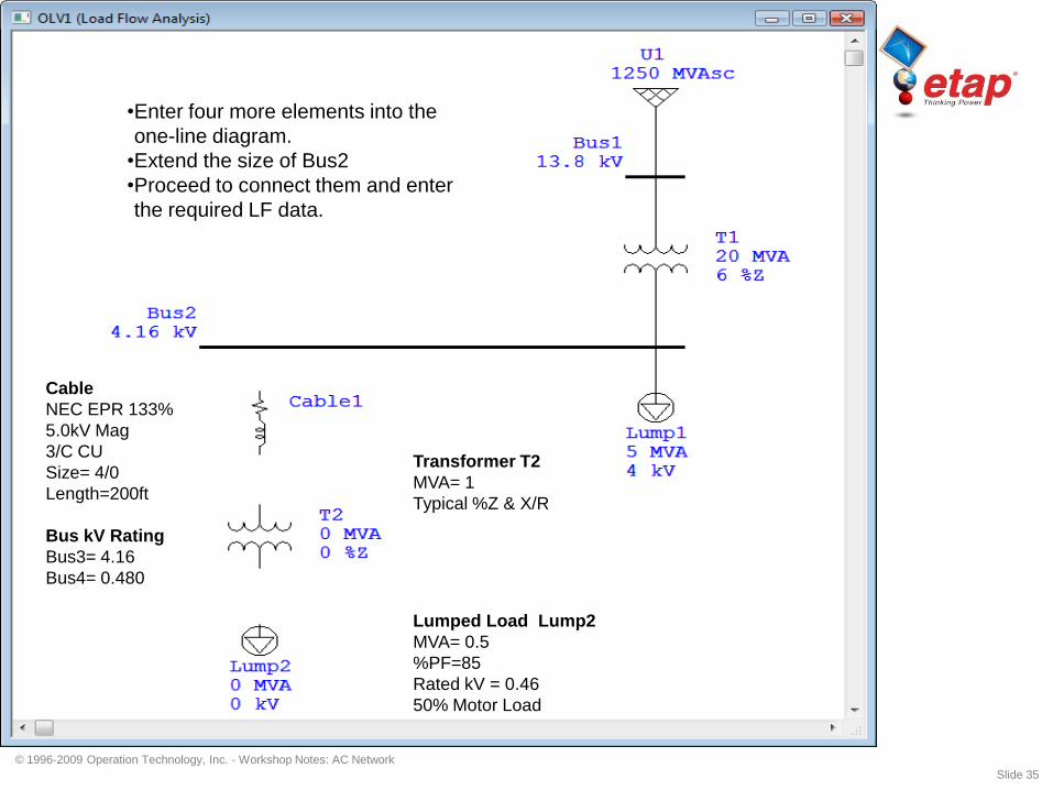
•Enter four more elements into the
one-line diagram.
•Extend the size of Bus2
•Proceed to connect them and enter
the required LF data.
Cable
NEC EPR 133%
5.0kV Mag
3/C CU
Size= 4/0
Length=200ft
Bus kV Rating
Bus3= 4.16
Bus4= 0.480
Lumped Load Lump2
MVA= 0.5
%PF=85
Rated kV = 0.46
50% Motor Load
Transformer T2
MVA= 1
Typical %Z & X/R

© 1996-2009 Operation Technology, Inc. - Workshop Notes: AC Network
Slide 36
Once all the elements have
been connected and the input
data has been entered, you
may proceed to run a Load
Flow Calculation.

© 1996-2009 Operation Technology, Inc. - Workshop Notes: AC Network
Slide 37
Gen1
Rating:
5 MW
Voltage Control
%PF = 80
Generation Category:
Design
MW = 5
Qmax = 5
Qmin = 1
• Extend the length of Bus2
towards the right side.
• Add a Generator Gen1
• Rotate Gen1 180º using
<SHIFT+R>
• Connect & proceed to enter
required input data for Load
Flow

© 1996-2009 Operation Technology, Inc. - Workshop Notes: AC Network
Slide 38
• Once the Generator has been
connected and the input data has been
entered, you may proceed to run a Load
Flow Calculation.

© 1996-2009 Operation Technology, Inc. - Workshop Notes: AC Network
Slide 39
2. Copy elements T1, Bus2,
Lump1, Cable1, T2, Bus4
and Lump2.
3. Move elements from
Dumpster and connect
them to Bus1.
4. Insert a normally open Tie
Breaker between Bus4 and
Bus5.
1. Extend the length of Bus1
towards the right side.
© 1996-2009 Operation Technology, Inc. - Workshop Notes: AC Network
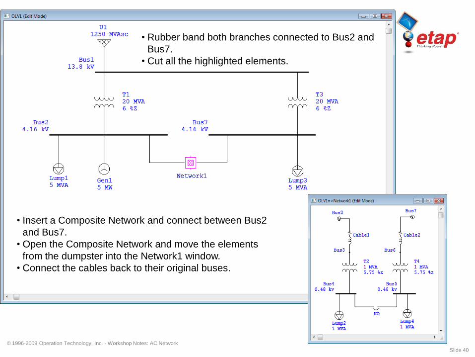
Slide 40
• Insert a Composite Network and connect between Bus2
and Bus7.
• Open the Composite Network and move the elements
from the dumpster into the Network1 window.
• Connect the cables back to their original buses.
• Rubber band both branches connected to Bus2 and
Bus7.
• Cut all the highlighted elements.

© 1996-2009 Operation Technology, Inc. - Workshop Notes: AC Network
Slide 41
• Insert High Voltage Circuit Breakers at the indicated
locations.
• Insert Low Voltage Circuit Breakers inside the
Composite network and place them before the
Lumped Loads.

© 1996-2009 Operation Technology, Inc. - Workshop Notes: AC Network
Slide 42
3D Database

© 1996-2009 Operation Technology, Inc. - Workshop Notes: AC Network
Slide 43
Study Conditions• Different Operating Requirements
Generator 1 in Voltage
Control Mode
Generator 1 in Swing Mode

© 1996-2009 Operation Technology, Inc. - Workshop Notes: AC Network
Slide 44
Study Conditions• Different Loading Conditions
Summer Loading Winter Loading

© 1996-2009 Operation Technology, Inc. - Workshop Notes: AC Network
Slide 45
Study Conditions• Different Configurations
Configuration Normal Configuration GenOFF

© 1996-2009 Operation Technology, Inc. - Workshop Notes: AC Network
Slide 46
Study Conditions• Different Engineering Data
Revision Base Revision Sub2a Mod

© 1996-2009 Operation Technology, Inc. - Workshop Notes: AC Network
Slide 47
3-D Database
Base & Revision Data
CB, Fuse, Switch,
Load, & Motor
Status
Properties
Presentations Configurations
Nameplate,
Rating, Loading,
Settings, Dimension, etc.
Symbol &
Annotation
Visibility,
Location,
& Size

© 1996-2009 Operation Technology, Inc. - Workshop Notes: AC Network
Slide 48
One-Line Diagrams
Impedance Diagrams
Relay Diagrams
Physical Diagrams
Study Diagrams
PresentationsSymbol &
Annotation
Visibility,
Location,
& Size

© 1996-2009 Operation Technology, Inc. - Workshop Notes: AC Network
Slide 49
Configurations
CB, Fuse, Switch,
Load, & Motor
Status

© 1996-2009 Operation Technology, Inc. - Workshop Notes: AC Network
Slide 50
Base & Revision Data
PropertiesProperties
Nameplate,
Rating, Loading,
Settings, Dimension, etc.

© 1996-2009 Operation Technology, Inc. - Workshop Notes: AC Network
Slide 51
User Access ManagementGroup 1 Functions
Move Elements
Change Element Size
Change Element Symbol
Change Element Orientation
Edit Engineering Properties
Change Operating Status
Hide or Show Protective Devices
Autoroute Connections
Change Bus to Node Symbols
Purge Data Revisions
Merge Data Revisions to Other Revisions

© 1996-2009 Operation Technology, Inc. - Workshop Notes: AC Network
Slide 52
User Access Management
Group 2 Functions
Add (Drop) Elements
Cut (Delete) Elements to Dumpster
Copy Elements from Dumpster
Paste Elements from Dumpster
Move Elements from Dumpster
Connect Elements
Purge Elements from Dumpster
Re-sizing Elements (UGS)
Merge Data Revision to Base Data
Graphical Adjustment of STAR
Views

© 1996-2009 Operation Technology, Inc. - Workshop Notes: AC Network
Slide 53
User Access Management
Group 3 Functions
Change Phase/Ground mode in
Star View.
Compute Time Difference in Star
View.
View Alerts.
View Device Setting Reports.
© 1996-2009 Operation Technology, Inc. - Workshop Notes: AC Network
Slide 54
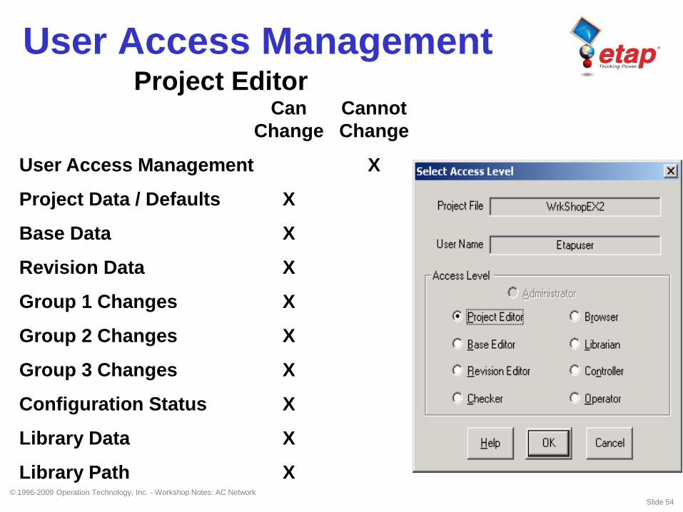
User Access ManagementProject Editor
Can Cannot
Change Change
User Access Management X
Project Data / Defaults X
Base Data X
Revision Data X
Group 1 Changes X
Group 2 Changes X
Group 3 Changes X
Configuration Status X
Library Data X
Library Path X
© 1996-2009 Operation Technology, Inc. - Workshop Notes: AC Network
Slide 55
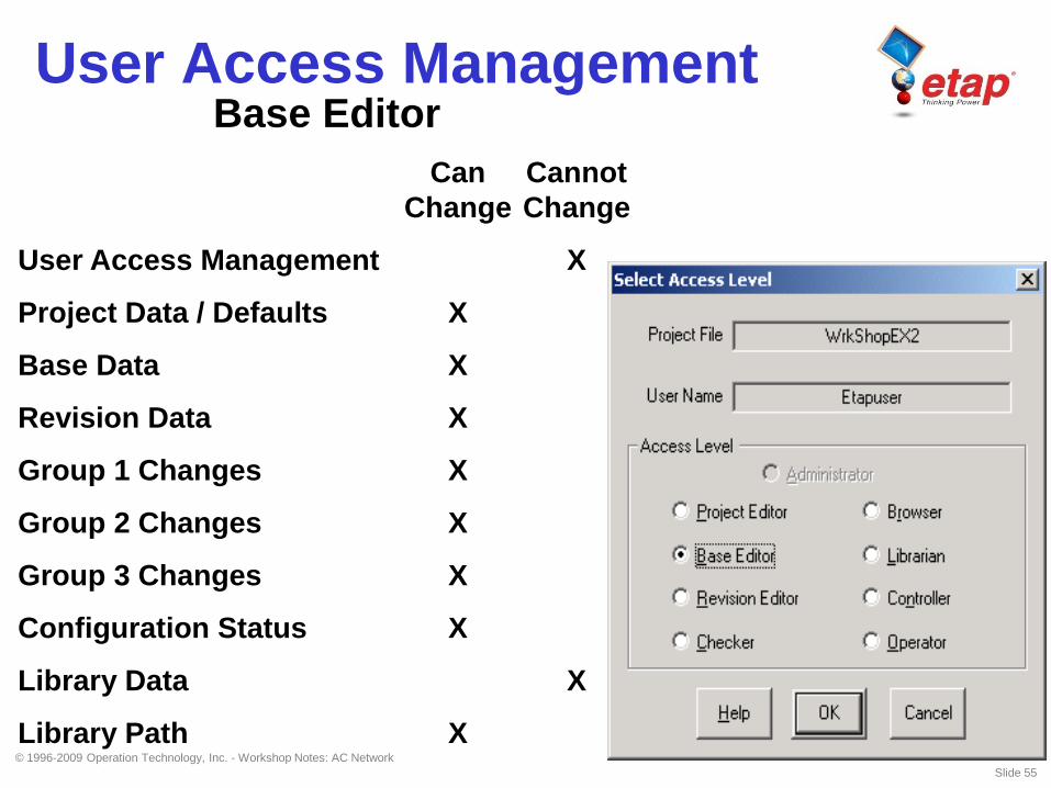
User Access ManagementBase Editor
Can Cannot
Change Change
User Access Management X
Project Data / Defaults X
Base Data X
Revision Data X
Group 1 Changes X
Group 2 Changes X
Group 3 Changes X
Configuration Status X
Library Data X
Library Path X

© 1996-2009 Operation Technology, Inc. - Workshop Notes: AC Network
Slide 56
User Access ManagementRevision Editor
Can Cannot
Change Change
User Access Management X
Project Data / Defaults X
Base Data X
Revision Data X
Group 1 Changes X
Group 2 Changes X
Group 3 Changes X
Configuration Status X
Library Data X
Library Path X

© 1996-2009 Operation Technology, Inc. - Workshop Notes: AC Network
Slide 57
User Access ManagementChecker
Can Cannot
Check Change
User Access Management X
Project Data / Defaults X
Base Data X X
Revision Data X X
Group 1 Changes X
Group 2 Changes X
Group 3 Changes – Can Change
Configuration Status X
Library Data X
Library Path X

© 1996-2009 Operation Technology, Inc. - Workshop Notes: AC Network
Slide 58
Circuit Arrangements
• Radial System
• Loop System
• Primary Selective System
• Secondary Selective System
© 1996-2009 Operation Technology, Inc. - Workshop Notes: AC Network
Slide 59
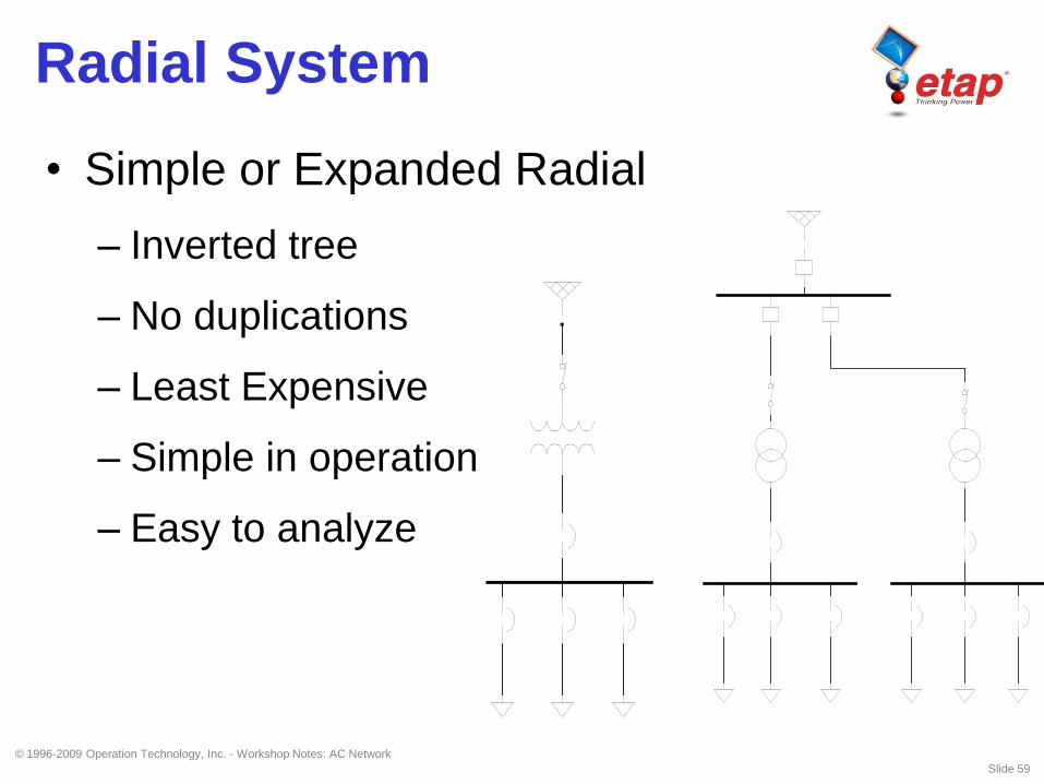
Radial System
• Simple or Expanded Radial
– Inverted tree
– No duplications
– Least Expensive
– Simple in operation
– Easy to analyze

© 1996-2009 Operation Technology, Inc. - Workshop Notes: AC Network
Slide 60
Loop System
• Interconnected / Open Point
• Loads are tapped of the loop
• Loop could be open or closed
• More difficult for analysis
• Reliable

© 1996-2009 Operation Technology, Inc. - Workshop Notes: AC Network
Slide 61
Primary Selective System
• Each transformer is supplied by two sources
• Normal operation is to supply half the load
from one source
• Manual or Automatic transfer of load
• Recommended

© 1996-2009 Operation Technology, Inc. - Workshop Notes: AC Network
Slide 62
Primary Selective System
© 1996-2009 Operation Technology, Inc. - Workshop Notes: AC Network
Slide 63
Secondary Selective System
• Each load can be supplied from either one of
the transformers
• The tie breaker is usually normally open
• If one of the transformers is out of service,
the tie breaker is closed and the total load is
supplied by the remaining transformer
• Very reliable system
![Cooja Simulator Manualyaramoozan.ir/wp-content/uploads/2017/02/آموزش-نصب-و... · Contiki website [1] may be a first port of call in regard to Cooja, and provides an image](https://img.pdfslide.us/doc/110x75/5ac2e6c37f8b9a1c768e8c0f/cooja-simulator-contiki-website-1-may-be-a-first-port-of.jpg)