Embed Size (px)
Citation preview

AC loss – part I
Fedor Gömöry
Institute of Electrical Engineering
Slovak Academy of Sciences
Dubravska cesta 9, 84101 Bratislava, Slovakia
[email protected] www.elu.sav.sk

Outline of Part I:
1. What is AC loss
2. Dissipation mechanisms: Resistive
Eddy currents
Flux pinning
Coupling currents
3. Possibilities for AC loss reduction
4. Methods to measure AC loss

Outline of Part I:
1. What is AC loss
2. Dissipation mechanisms: Resistive
Eddy currents
Flux pinning
Coupling currents
3. Possibilities for AC loss reduction
4. Methods to measure AC loss

What is understood under AC loss
= amount of heat
released during operation in cyclic (or transient) regime
it does not appear in DC regime
is not a property of material but of a (superconducting) object
operating in well defined conditions
(temperature, transported current, applied magnetic field)

Outline of Part I:
1. What is AC loss
2. Dissipation mechanisms: Resistive
Eddy currents
Flux pinning
Coupling currents
3. Possibilities for AC loss reduction
4. Methods to measure AC loss

Resistive AC loss
does not fall under the definition of AC loss
because it is due to static E(j) relation
can be calculated from E(j)
should be marginal in nominal operating regime
1.E-04
1.E-03
1.E-02
1.E-01
1.E+00
1.E+01
1.E+02
10 100
I rms [A]
P [
W/m
]
36 Hz
72 Hz
144 Hz
36 Hz
72 Hz
144 Hz
36 Hz
72 Hz
144 Hz
P res
P mag
P tran- data
P tran- model
j
E
Outline of Part I:
1. What is AC loss
2. Dissipation mechanisms: Resistive
Eddy currents
Flux pinning
Coupling currents
3. Possibilities for AC loss reduction
4. Methods to measure AC loss

Eddy current loss
induced currents in metallic parts
treated in textbooks of electromagnetism (skin effect, inductive heating)
penetration depth
shielding of magnetic field if d << wall thickness
negligible if d >> thickness of metallic object
should be marginal in nominal operating regime
d
0
2
metal resistivity
frequency (angular)
magnetic permeability of vacuum

Outline of Part I:
1. What is AC loss
2. Dissipation mechanisms: Resistive
Eddy currents
Flux pinning
Coupling currents
3. Possibilities for AC loss reduction
4. Methods to measure AC loss

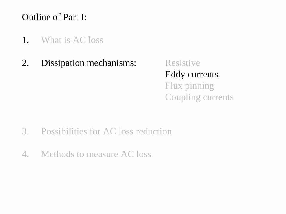
Hysteresis loss in superconductor
because of magnetic flux pinning in superconductor
(the mechanism securing high current transport capacity i.e. large critical current density in magnetic fields >> 1 T )
“hard” = type II superconductor with flux pinning
critical state model – Ch. P. Bean 1962:
cj
j0 in the places that never experienced electrical field
elsewhere
simplest version: jc independent of E, B
jc = const. sometimes call “the Bean model”

Transport of electrical current
e.g. the critical current measurement
0 A 20 A 100 A
80 A 20 A 0 A
j =+ jc
j =- jc
j =0
I

Transport of electrical current
AC cycle with Ia less than Ic : neutral zone
80 60 -80 -60 0 A

T
IdIUdtQ
neutral zone:
j =0, E = 0
U
t
ΦU
check for hysteresis in I vs. plot
AC transport in hard superconductor : is it still without dissipation?

AC transport loss in hard superconductor
-1.5E-05
-1.0E-05
-5.0E-06
0.0E+00
5.0E-06
1.0E-05
1.5E-05
-150 -100 -50 0 50 100 150
[V
s/m
]
I [A]
hysteresis dissipation AC loss

AC transport loss in hard superconductor
hysteresis dissipation AC loss
-1.5E-05
-1.0E-05
-5.0E-06
0.0E+00
5.0E-06
1.0E-05
1.5E-05
-150 -100 -50 0 50 100 150
[V
s/m
]
I [A]
Hard superconductor in changing magnetic field
0 30 50 40 mT
0 -50 -40 0 50 mT

volume loss density Q [J/m3]
magnetization:
Hard superconductor in changing magnetic field
dissipation because of flux pinning
MBV
Qad
S
yxyxjxM dd),(.
Ba
x
y

Round wire from hard superconductor in changing magnetic field
-3.E+04
-2.E+04
-1.E+04
0.E+00
1.E+04
2.E+04
3.E+04
-0.06 -0.04 -0.02 0 0.02 0.04 0.06
M [
A/m
]
B [T]
Bp
Ms
Ms saturation magnetization, Bp penetration field

Round wire from hard superconductor in changing magnetic field
-3.E+04
-2.E+04
-1.E+04
0.E+00
1.E+04
2.E+04
3.E+04
-0.25 -0.2 -0.15 -0.1 -0.05 0 0.05 0.1 0.15 0.2 0.25
M [
A/m
]
B [T]
estimation of AC loss at Ba >> Bp
saMBV
Q4
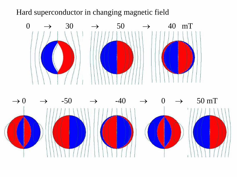
Slab in parallel magnetic field – analytical solution
saMBQ 4
j
B penetration field
w
20
wjB cp
2
3
0
3
42
3
2
1
pap
p
a
BBB
B
B
V
Q
024
p
cs
BwjM

Slab in parallel magnetic field – analytical solution
saMBQ 4
1.E-08
1.E-07
1.E-06
1.E-05
1.E-04
1.E-03
1.E-02
1.E-01
1.E+00
1.E+01
1.E+02
1.E+03
1.E+04
1.E+05
1.E-05 1.E-04 1.E-03 1.E-02 1.E-01 1.E+00
Q/V
[J/m
]
Ba [T]
jc=10^8 A/m2, w=1 mm (Bp = 63 mT)
jc=10^8 A/m2, w=0.1 mm (Bp = 6.3 mT)
jc=10^7 A/m2, w=1 mm (Bp = 6.3 mT)
jc=10^7 A/m2, w=0.1 mm (Bp = 0.63 mT)

Outline of Part I:
1. What is AC loss
2. Dissipation mechanisms: Resistive
Eddy currents
Flux pinning
Coupling currents
3. Possibilities for AC loss reduction
4. Methods to measure AC loss

Coupling loss - two parallel superconducting wires in metallic matrix
coupling currents
Ba
0 20 80 60 mT
in the case of a perfect coupling:

Magnetization of two parallel wires
-2.E+05
-1.E+05
-5.E+04
0.E+00
5.E+04
1.E+05
2.E+05
-0.15 -0.1 -0.05 0 0.05 0.1 0.15
M [
A/m
]
B [T]
coupled:
uncoupled:
how to reduce the coupling currents ?

Composite wires – twisted filaments
B
j
B
lp
t
pBlj
2
1
1
1
1
mt
mtgood interfaces
bad interfaces
m
SC
S
S

Composite wires – twisted filaments
coupling currents (partially) screen the applied field
BBBi - time constant of magnetic flux diffusion
2
0
22
p
t
l
22
0
2
max
1
2
B
V
Q22
0
0
2
max
1
B
V
Q
round wireflat wire
A.Campbell (1982) Cryogenics 22 3
K. Kwasnitza, S. Clerc (1994) Physica C 233 423
K. Kwasnitza, S. Clerc, R. Flukiger, Y. Huang (1999)
Cryogenics 39 829
Around2
0

Outline of Part I:
1. What is AC loss
2. Dissipation mechanisms: Resistive
Eddy currents
Flux pinning
Coupling currents
3. Possibilities for AC loss reduction
4. Methods to measure AC loss

Hysteresis loss:
at large fields proportional to Bp ~ jc w
= loss reduction by either lower jc or reduced w
lowering of jc would mean more superconducting material required to transport the same current
thus only plausible way is the reduction of w
width of superconductor
(perpendicular to the applied
magnetic field)

effect of the field orientation
saMBV
Q4
-2.E+05
-1.E+05
-5.E+04
0.E+00
5.E+04
1.E+05
2.E+05
-0.15 -0.1 -0.05 0 0.05 0.1 0.15
M [
A/m
]
B [T]
perpendicular field
parallel field
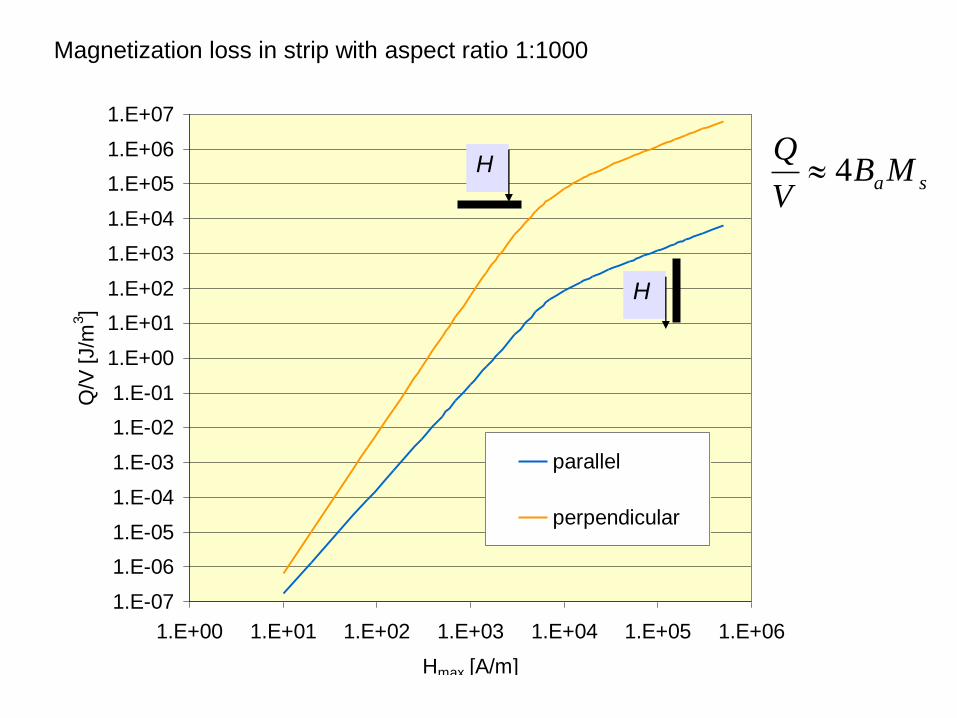
Magnetization loss in strip with aspect ratio 1:1000
1.E-07
1.E-06
1.E-05
1.E-04
1.E-03
1.E-02
1.E-01
1.E+00
1.E+01
1.E+02
1.E+03
1.E+04
1.E+05
1.E+06
1.E+07
1.E+00 1.E+01 1.E+02 1.E+03 1.E+04 1.E+05 1.E+06
Hmax [A/m]
Q/V
[J/m
3]
parallel
perpendicular
H
H
saMBV
Q4

in the case the tape orientation is not a free parameter
= reduction of the tape width
striation of CC tapes
BB
~ 6 times lower hysteresis loss

striation of CC tapes
but in operation the filaments are connected at magnet terminations
BB
coupling loss will be the main issue

Coupling loss:
at low frequencies proportional to
= filaments (in single tape) or tapes (in a cable)
should be transposed
= low loss requires high inter-filament or inter-tape resistivity
but good stability needs the opposite
transposition length
effective resistivity
2
0
22
p
t
l

Outline of Part I:
1. What is AC loss
2. Dissipation mechanisms: Resistive
Eddy currents
Flux pinning
Coupling currents
3. Possibilities for AC loss reduction
4. Methods to measure AC loss

Experimental methods for AC loss determination
• Tape
• Cable
• Magnet

Experimental methods for AC loss determination
Shape of the excitation field (current) pulse
transition unipolar harmonic
relevant information can be
achieved in harmonic regime
final testing necessary in
actual regime

Experimental methods for AC loss determination
1.Thermal a) cooling power (large devices)
b) boil-off
c) temperature profile
2. Electrical - lock-in technique
- Y(I) hysteresis loop registration

temperature profile method
Thermocouple
Voltage
taps
Thermal
insulation
Current DC,
AC
1.E-06
1.E-05
1.E-04
1.E-03
1.E-02
1.E-01
1 10 100
Irms [A]
P [
W/m
]
P thermal
P electrical
y = 0.1677x + 0.1452
0
1
2
3
4
5
6
0 5 10 15 20 25 30
P [mW/m]
Utc
[uV
]
Series1
Linear (Series1)
P = (Utc-.145)/.168
P~T

AC power
supplyAC power flow
AC loss in
SC object
cycleAC1
ower.dtPQ
Tt
t
tUQ (t)I(t).d„Power meter“
Lock-in amplifier
Electrical method

Electrical method
Lock-in amplifier
(phase sensitive detection at fundamental component)
so called in-phase and out-of-phase signals
2
0
2
0
dcos)(1
dsin)(1
tttuU
tttuU
mC
mS
reference signal necessary to set the
frequency
phase
taken from AC current
um - measured voltage

Fundamental problem of electrical methods for AC loss determination
AC power
supplyAC power flow
AC loss in
SC object

Solution 1- detection of power flow to the sample
AC power
supplyAC power flow
AC loss in
SC object

Solution 2- elimination of parasitic power flows
AC power
supplyAC power flow
AC loss in
SC object
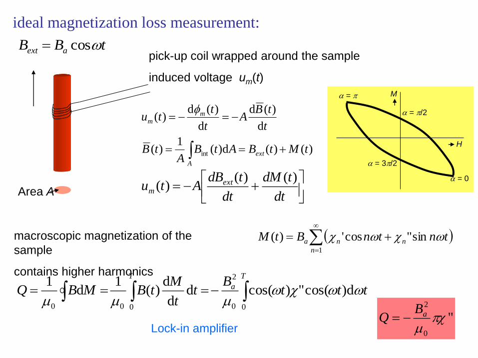
ideal magnetization loss measurement:
tBB aext cos
Area A
)()(d)(1
)(
d
)(d
d
)(d)(
int tMtBAtBA
tB
t
tBA
t
ttu
ext
A
mm
pick-up coil wrapped around the sample
induced voltage um(t)
macroscopic magnetization of the
sample
contains higher harmonics
dt
tdM
dt
tdBAtu ext
m
)()()(
( )
1
sin"cos')(n
nna tntnBtM
tttB
tt
MtBMBQ
T
a
T
d)cos(")cos(dd
d)(
1d
1
00
2
000
H
M
= 0
=
= /2
= 3/2
"0
2
aBQ
Lock-in amplifier

Real magnetization loss measurement:
Pick-up coil
sample
Calibration necessary
tuCM d
by means of:
measurement on a sample
with known properrties
calibration coil
numerical calculation
…

Loss measurement from the side of AC power supply:
AMPLIFIER
LOCK-IN
channel A
channel B
generator
Rogowski
coil
transformer
LN2
Im sample
Bmsample UIP power supply
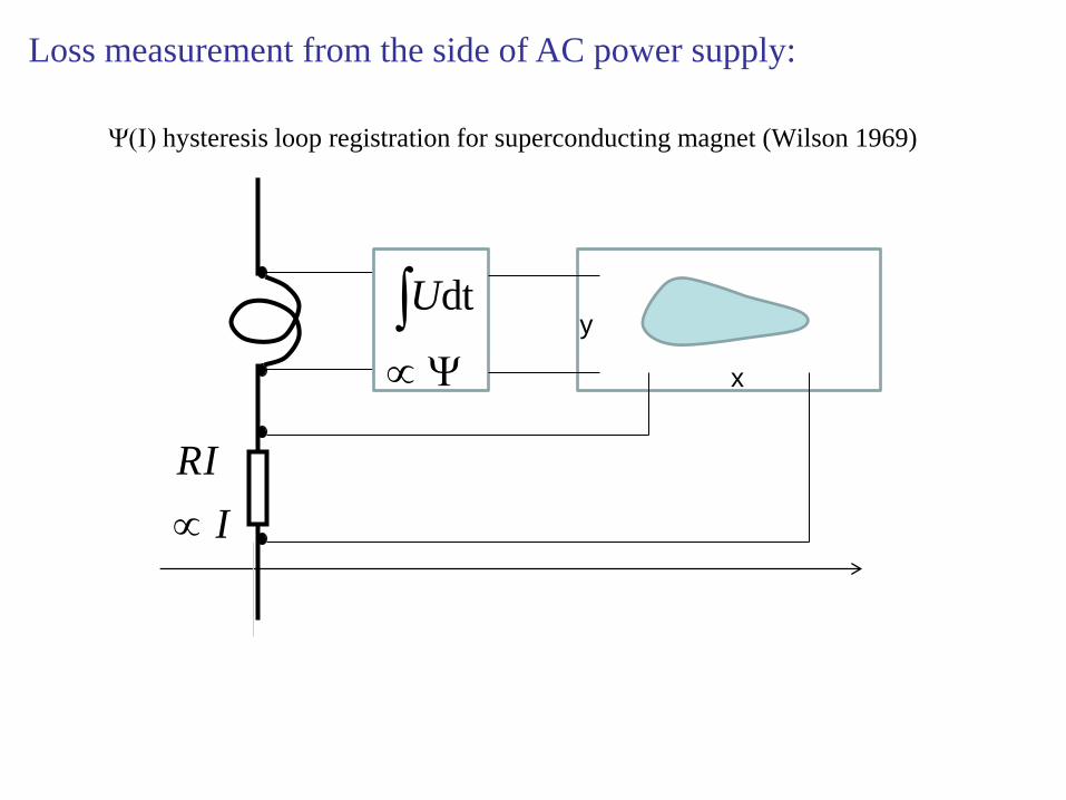
Loss measurement from the side of AC power supply:
Y(I) hysteresis loop registration for superconducting magnet (Wilson 1969)
Y
dtU
I
RI
x
y
![LABORATORIES - xray.cz · jozef.sevcik@savba.sk Key words : ... ac ter ized at our In stitute [1, 2, 3] . ... Dodson at the Un i ver sity of York for co op er a ti on](https://img.pdfslide.us/doc/110x75/5abfc9417f8b9add5f8e29b7/laboratories-xraycz-savbask-key-words-ac-ter-ized-at-our-in-stitute-1.jpg)