Embed Size (px)
Citation preview
Leader Evaporator Co., Inc.
49 Jonergin Drive
Swanton, VT 05488
Tel: 802-868-5444
www.leaderevaporator.com
AC Fill Stop Valve Instructions
AC Fill Stop Valve Instructions Page: 1
Contents
INTRODUCTION / DESCRIPTION ............................................... 2
EQUIPMENT DESCRIPTION ....................................................... 2
Optional Setup and Replacement Parts ................................... 3
SETUP / INSTALLATION .............................................................. 4
USE / OPERATION ....................................................................... 9
MAINTENANCE .......................................................................... 11
FEEDBACK: ................................................................................ 13
NOTES: ....................................................................................... 13
AC Fill Stop Valve Instructions Page: 2
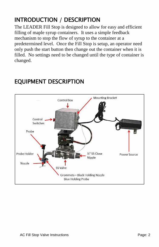
INTRODUCTION / DESCRIPTION The LEADER Fill Stop is designed to allow for easy and efficient
filling of maple syrup containers. It uses a simple feedback
mechanism to stop the flow of syrup to the container at a
predetermined level. Once the Fill Stop is setup, an operator need
only push the start button then change out the container when it is
filled. No settings need to be changed until the type of container is
changed.
EQUIPMENT DESCRIPTION
AC Fill Stop Valve Instructions Page: 3
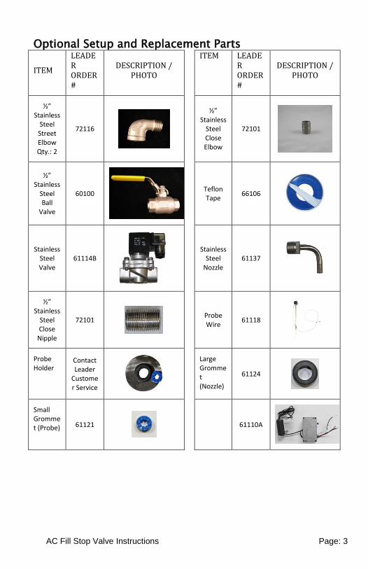
Optional Setup and Replacement Parts
ITEM
LEADER ORDER #
DESCRIPTION / PHOTO
ITEM LEADER ORDER #
DESCRIPTION / PHOTO
½” Stainless
Steel Street Elbow Qty.: 2
72116
½” Stainless
Steel Close Elbow
72101
½” Stainless
Steel Ball
Valve
60100
Teflon Tape
66106
Stainless Steel Valve
61114B
Stainless Steel
Nozzle 61137
½” Stainless
Steel Close
Nipple
72101
Probe Wire
61118
Probe Holder
Contact Leader
Customer Service
Large Grommet (Nozzle)
61124
Small Grommet (Probe) 61121
61110A
AC Fill Stop Valve Instructions Page: 4
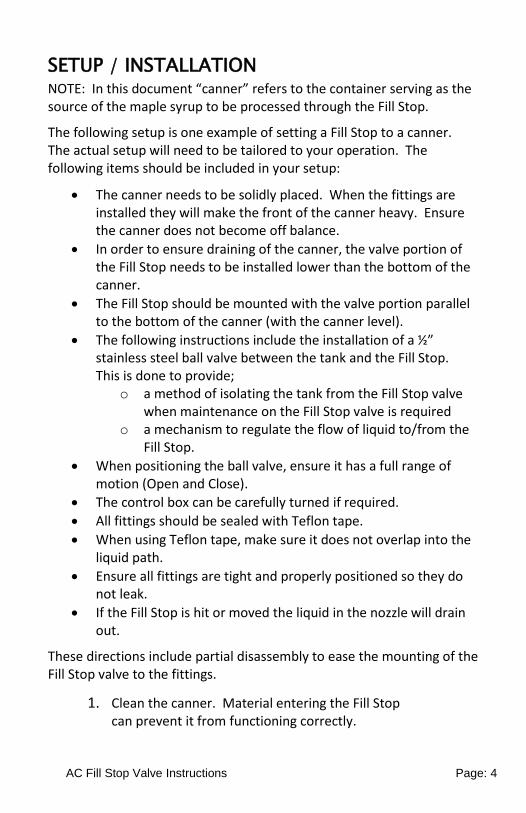
SETUP / INSTALLATION NOTE: In this document “canner” refers to the container serving as the source of the maple syrup to be processed through the Fill Stop.
The following setup is one example of setting a Fill Stop to a canner. The actual setup will need to be tailored to your operation. The following items should be included in your setup:
The canner needs to be solidly placed. When the fittings are installed they will make the front of the canner heavy. Ensure the canner does not become off balance.
In order to ensure draining of the canner, the valve portion of the Fill Stop needs to be installed lower than the bottom of the canner.
The Fill Stop should be mounted with the valve portion parallel to the bottom of the canner (with the canner level).
The following instructions include the installation of a ½” stainless steel ball valve between the tank and the Fill Stop. This is done to provide;
o a method of isolating the tank from the Fill Stop valve when maintenance on the Fill Stop valve is required
o a mechanism to regulate the flow of liquid to/from the Fill Stop.
When positioning the ball valve, ensure it has a full range of motion (Open and Close).
The control box can be carefully turned if required.
All fittings should be sealed with Teflon tape.
When using Teflon tape, make sure it does not overlap into the liquid path.
Ensure all fittings are tight and properly positioned so they do not leak.
If the Fill Stop is hit or moved the liquid in the nozzle will drain out.
These directions include partial disassembly to ease the mounting of the Fill Stop valve to the fittings.
1. Clean the canner. Material entering the Fill Stop can prevent it from functioning correctly.
AC Fill Stop Valve Instructions Page: 5
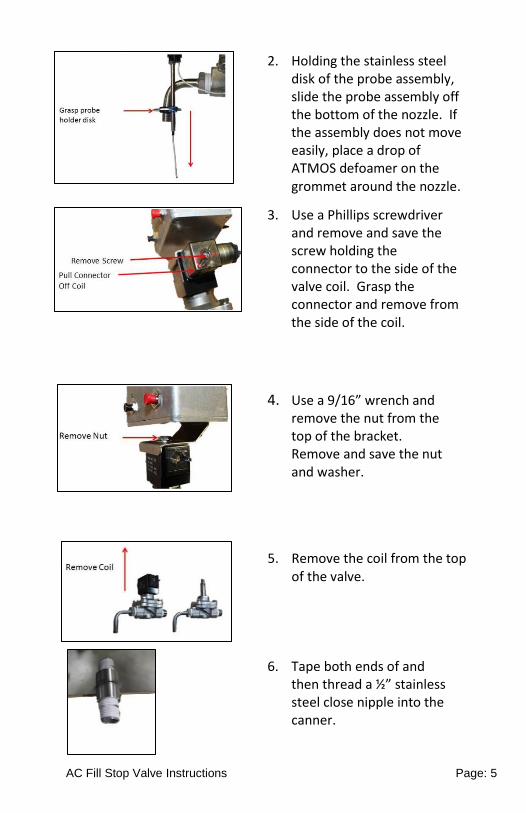
2. Holding the stainless steel disk of the probe assembly, slide the probe assembly off the bottom of the nozzle. If the assembly does not move easily, place a drop of ATMOS defoamer on the grommet around the nozzle.
3. Use a Phillips screwdriver and remove and save the screw holding the connector to the side of the valve coil. Grasp the connector and remove from the side of the coil.
4. Use a 9/16” wrench and remove the nut from the top of the bracket. Remove and save the nut and washer.
5. Remove the coil from the top of the valve.
6. Tape both ends of and then thread a ½” stainless steel close nipple into the canner.
AC Fill Stop Valve Instructions Page: 6
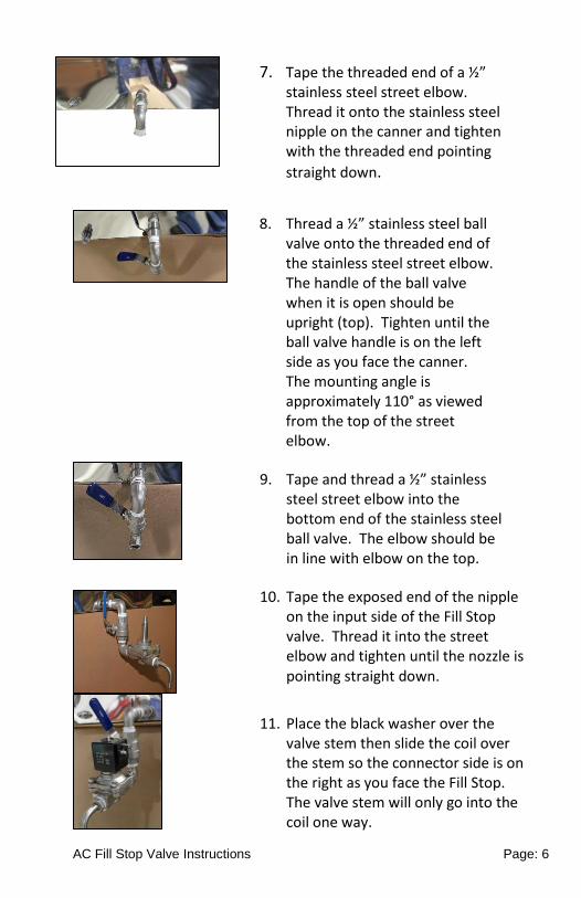
7. Tape the threaded end of a ½” stainless steel street elbow. Thread it onto the stainless steel nipple on the canner and tighten with the threaded end pointing
straight down.
8. Thread a ½” stainless steel ball valve onto the threaded end of the stainless steel street elbow. The handle of the ball valve when it is open should be upright (top). Tighten until the ball valve handle is on the left side as you face the canner. The mounting angle is approximately 110° as viewed from the top of the street elbow.
9. Tape and thread a ½” stainless steel street elbow into the bottom end of the stainless steel ball valve. The elbow should be in line with elbow on the top.
10. Tape the exposed end of the nipple on the input side of the Fill Stop valve. Thread it into the street elbow and tighten until the nozzle is pointing straight down.
11. Place the black washer over the valve stem then slide the coil over the stem so the connector side is on the right as you face the Fill Stop. The valve stem will only go into the coil one way.
AC Fill Stop Valve Instructions Page: 7
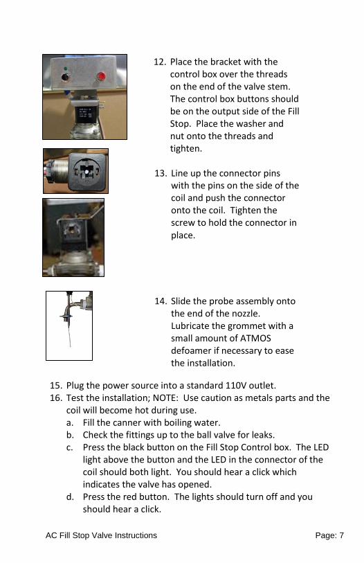
15. Plug the power source into a standard 110V outlet. 16. Test the installation; NOTE: Use caution as metals parts and the
coil will become hot during use. a. Fill the canner with boiling water. b. Check the fittings up to the ball valve for leaks. c. Press the black button on the Fill Stop Control box. The LED
light above the button and the LED in the connector of the coil should both light. You should hear a click which indicates the valve has opened.
d. Press the red button. The lights should turn off and you should hear a click.
13. Line up the connector pins with the pins on the side of the coil and push the connector onto the coil. Tighten the screw to hold the connector in place.
12. Place the bracket with the control box over the threads on the end of the valve stem. The control box buttons should be on the output side of the Fill Stop. Place the washer and nut onto the threads and tighten.
14. Slide the probe assembly onto the end of the nozzle. Lubricate the grommet with a small amount of ATMOS defoamer if necessary to ease the installation.
AC Fill Stop Valve Instructions Page: 8
e. Press the black button on the Fill Stop Control box. The LED light above the button and the LED in the connector of the coil should both light. You should hear a click which indicates the valve has opened.
f. Touch the exposed end of the probe wire to the nozzle. The lights should turn off and you should hear a click.
g. Slowly open the ball valve and check the section between the ball valve and the Fill Stop for leaks.
h. Place an open top container (such as a measuring cup) under the nozzle.
i. Press the black button on the Fill Stop Control box. The LED light above the button and the LED in the connector of the coil should both light. You should hear a click which indicates the valve has opened. Water should flow from the nozzle.
j. Press the red button. The lights should turn off and the water should stop flowing. Observe the assembly for approximately 1 minute to ensure there are no drips. If dripping is noted refer to the Maintenance Section on how to disassemble and clean the valve. If after cleaning the Fill Stop continues to drip contact Leader Customer Service.
k. Press the black button on the Fill Stop Control box. The LED light above the button and the LED in the connector of the coil should both light and the water should again flow from the nozzle.
l. Touch the exposed end of the probe wire to the stream of water. The lights should turn off and the flow of water should stop. Again observe the Fill Stop for approximately 1 minute for drips.
m. Unplug the Fill Stop. No water should be released.
AC Fill Stop Valve Instructions Page: 9
USE / OPERATION To use the Fill Stop you will need to set the probe for the level of syrup to be put into a specific style container to be filled. It is recommended you practice, using water, setting the levels and valve openings on all the different styles of containers you will be using.
CAUTION: When operating the Fill Stop all metal parts will become hot.
1. Fill the canner with the syrup to be put into containers. Heat the syrup as necessary. Maple syrup should be heated to 180°F to 190°F (with the higher temperature recommended for glass containers).
2. Turn power on to the Fill Stop. Open the stainless steel valve all the way.
3. Place a clean container such as a measuring cup to collect the maple syrup under the nozzle.
4. Push the black button and allow the maple syrup to flow until there is a smooth flow coming from the nozzle (no air bubbles, etc.). You can return the syrup to the canner.
5. The Fill Stop needs to be adjusted for each TYPE/SIZE of container to be filled.
6. Select a container to be filled and place it under the nozzle.
7. Insert the probe wire into the container. The probe wire should be as straight (in line with the stainless steel probe tube) as possible. The exposed end of the probe wire should not be in the path of the syrup from the nozzle or the container if it is metal.
8. To determine the correct height, start with the probe wire well into the container
9. Push the black Start button on the control box and allow the container to fill until it stops. Adjust the probe wire up or down until the proper level of liquid is reached. NOTE: If there is foaming in the container the sensor will not work properly. To minimize foam, adjust the ball valve so the flow entering into the container is smooth.
AC Fill Stop Valve Instructions Page: 10
10. When a container is filled pull it out from under the probe wire. You can place another of the same size and style container into position to fill. Make sure the probe wire is set straight into each container to be filled.
11. Continue filling the containers until the canner is empty or another size/style of container is to be filled. If the canner is emptied go to step 1. If a new size container is to be used go to step 6.
AC Fill Stop Valve Instructions Page: 11
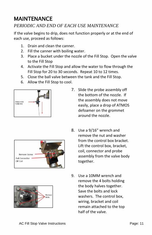
MAINTENANCE PERIODIC AND END OF EACH USE MAINTENANCE
If the valve begins to drip, does not function properly or at the end of each use, proceed as follows:
1. Drain and clean the canner. 2. Fill the canner with boiling water. 3. Place a bucket under the nozzle of the Fill Stop. Open the valve
to the Fill Stop 4. Activate the Fill Stop and allow the water to flow through the
Fill Stop for 20 to 30 seconds. Repeat 10 to 12 times. 5. Close the ball valve between the tank and the Fill Stop. 6. Allow the Fill Stop to cool.
7. Slide the probe assembly off the bottom of the nozzle. If the assembly does not move easily, place a drop of ATMOS defoamer on the grommet around the nozzle.
8. Use a 9/16” wrench and remove the nut and washer from the control box bracket. Lift the control box, bracket, coil, connector and probe assembly from the valve body together.
9. Use a 10MM wrench and remove the 4 bolts holding the body halves together. Save the bolts and lock washers. The control box, wiring, bracket and coil remain attached to the top half of the valve.
10. Lift the top half of the valve body from the valve. The diaphragm may adhere to the
AC Fill Stop Valve Instructions Page: 12
15. Place the diaphragm onto the lower half of the valve body so the holes of the diaphragm line up with the holes in the valve body and the hole in the diaphragm is over the inlet side of the valve (valve body is labeled “IN”). Put the spring into the hole in the top of the actuator piston.
16. Insert the 4 bolts and lock washers into the holes and finger tighten. Use a 10MM wrench and tighten the bolts.
17. Place the black washer over the valve stem then slide the coil over the stem so the connector side is on the right as you face the Fill Stop. The valve stem will only go into the coil one way.
18. Place the bracket with the control box over the threads on the end of the valve stem. The control box buttons should be on the output side of the Fill Stop. Place the washer and nut onto the threads and tighten.
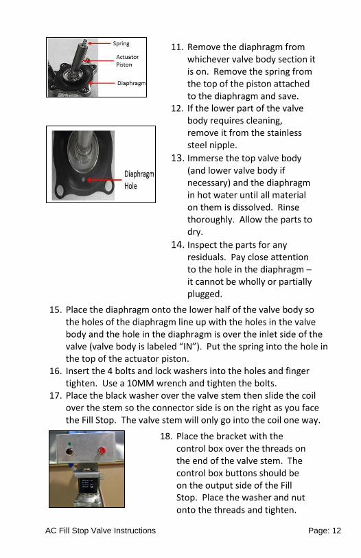
11. Remove the diaphragm from whichever valve body section it is on. Remove the spring from the top of the piston attached to the diaphragm and save.
12. If the lower part of the valve body requires cleaning, remove it from the stainless steel nipple.
13. Immerse the top valve body (and lower valve body if necessary) and the diaphragm in hot water until all material on them is dissolved. Rinse thoroughly. Allow the parts to dry.
14. Inspect the parts for any residuals. Pay close attention to the hole in the diaphragm – it cannot be wholly or partially plugged.
AC Fill Stop Valve Instructions Page: 13
FEEDBACK: Please use the following e-mail address ([email protected]) to suggest improvements or enter comments on this document. Reference the document title in your note. You may also contact LEADER Customer Service.
NOTES:
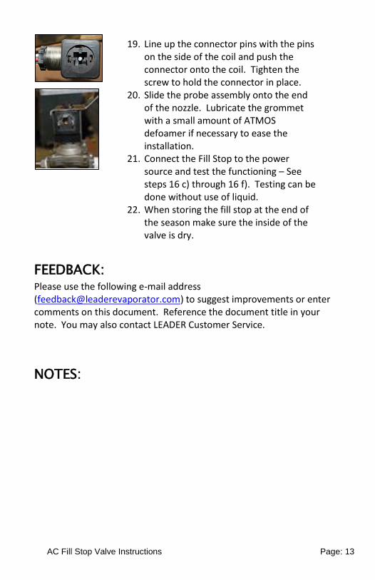
19. Line up the connector pins with the pins on the side of the coil and push the connector onto the coil. Tighten the screw to hold the connector in place.
20. Slide the probe assembly onto the end of the nozzle. Lubricate the grommet with a small amount of ATMOS defoamer if necessary to ease the installation.
21. Connect the Fill Stop to the power source and test the functioning – See steps 16 c) through 16 f). Testing can be done without use of liquid.
22. When storing the fill stop at the end of the season make sure the inside of the valve is dry.