Embed Size (px)
Citation preview
University of Technology Lecture Note 09 Electrical Engineering Department AC-AC Converters: AC Chopper Electrical Engineering Division Page 1 of 16 EG 405: Power Electronics Dr. Oday A. Ahmed
AC-AC Converters
AC Choppers A power electronic ac–ac converter, in generic form, accepts electric power from one system and converts it for delivery to another ac system with waveforms of different amplitude, frequency, and phase. They may be single-phase or three-phase types depending on their power ratings.
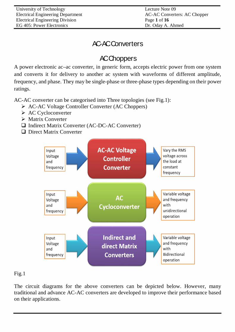
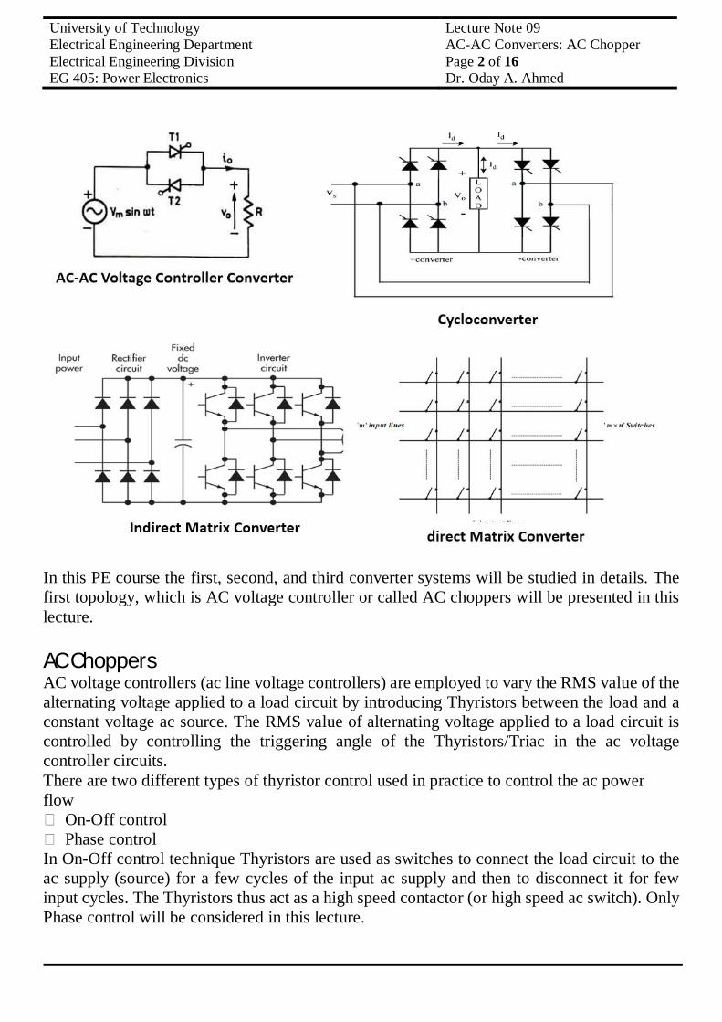
AC-AC converter can be categorised into Three topologies (see Fig.1): AC-AC Voltage Controller Converter (AC Choppers) AC Cycloconverter Matrix Converter Indirect Matrix Converter (AC-DC-AC Converter) Direct Matrix Converter
Fig.1 The circuit diagrams for the above converters can be depicted below. However, many traditional and advance AC-AC converters are developed to improve their performance based on their applications.
University of Technology Lecture Note 09 Electrical Engineering Department AC-AC Converters: AC Chopper Electrical Engineering Division Page 2 of 16 EG 405: Power Electronics Dr. Oday A. Ahmed
In this PE course the first, second, and third converter systems will be studied in details. The first topology, which is AC voltage controller or called AC choppers will be presented in this lecture. AC Choppers AC voltage controllers (ac line voltage controllers) are employed to vary the RMS value of the alternating voltage applied to a load circuit by introducing Thyristors between the load and a constant voltage ac source. The RMS value of alternating voltage applied to a load circuit is controlled by controlling the triggering angle of the Thyristors/Triac in the ac voltage controller circuits. There are two different types of thyristor control used in practice to control the ac power flow
On-Off control Phase control
In On-Off control technique Thyristors are used as switches to connect the load circuit to the ac supply (source) for a few cycles of the input ac supply and then to disconnect it for few input cycles. The Thyristors thus act as a high speed contactor (or high speed ac switch). Only Phase control will be considered in this lecture.
University of Technology Lecture Note 09 Electrical Engineering Department AC-AC Converters: AC Chopper Electrical Engineering Division Page 3 of 16 EG 405: Power Electronics Dr. Oday A. Ahmed
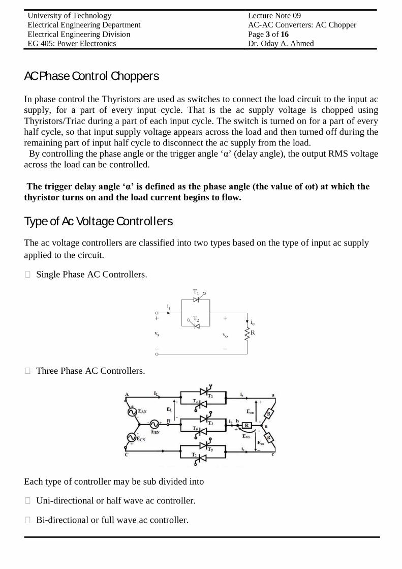
AC Phase Control Choppers In phase control the Thyristors are used as switches to connect the load circuit to the input ac supply, for a part of every input cycle. That is the ac supply voltage is chopped using Thyristors/Triac during a part of each input cycle. The switch is turned on for a part of every half cycle, so that input supply voltage appears across the load and then turned off during the remaining part of input half cycle to disconnect the ac supply from the load. By controlling the phase angle or the trigger angle ‘α’ (delay angle), the output RMS voltage across the load can be controlled. The trigger delay angle ‘α’ is defined as the phase angle (the value of ωt) at which the thyristor turns on and the load current begins to flow. Type of Ac Voltage Controllers The ac voltage controllers are classified into two types based on the type of input ac supply applied to the circuit.
Single Phase AC Controllers.
Three Phase AC Controllers.
Each type of controller may be sub divided into
Uni-directional or half wave ac controller.
Bi-directional or full wave ac controller.

University of Technology Lecture Note 09 Electrical Engineering Department AC-AC Converters: AC Chopper Electrical Engineering Division Page 4 of 16 EG 405: Power Electronics Dr. Oday A. Ahmed
Applications of Ac Voltage Controllers
Lighting / Illumination control in ac power circuits. Induction heating. Industrial heating & Domestic heating. Transformer tap changing (on load transformer tap changing). Speed control of induction motors (single phase and poly phase ac induction motor control).
Principle of AC Phase Control Half wave AC phase controller (Unidirectional Controller)
RMS Output Voltage
University of Technology Lecture Note 09 Electrical Engineering Department AC-AC Converters: AC Chopper Electrical Engineering Division Page 5 of 16 EG 405: Power Electronics Dr. Oday A. Ahmed
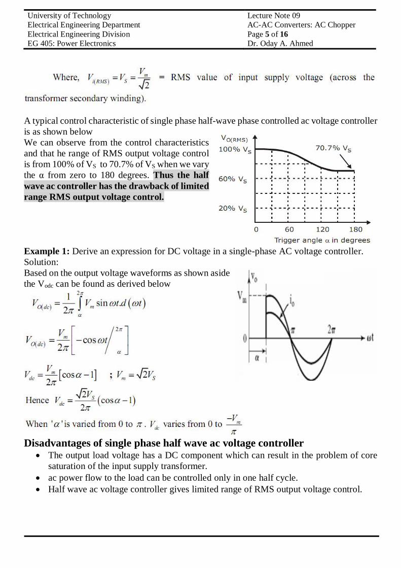
A typical control characteristic of single phase half-wave phase controlled ac voltage controller is as shown below We can observe from the control characteristics and that he range of RMS output voltage control is from 100% of VS to 70.7% of VS when we vary the α from zero to 180 degrees. Thus the half wave ac controller has the drawback of limited range RMS output voltage control. Example 1: Derive an expression for DC voltage in a single-phase AC voltage controller. Solution: Based on the output voltage waveforms as shown aside the Vodc can be found as derived below
Disadvantages of single phase half wave ac voltage controller
The output load voltage has a DC component which can result in the problem of core saturation of the input supply transformer.
ac power flow to the load can be controlled only in one half cycle. Half wave ac voltage controller gives limited range of RMS output voltage control.
University of Technology Lecture Note 09 Electrical Engineering Department AC-AC Converters: AC Chopper Electrical Engineering Division Page 6 of 16 EG 405: Power Electronics Dr. Oday A. Ahmed
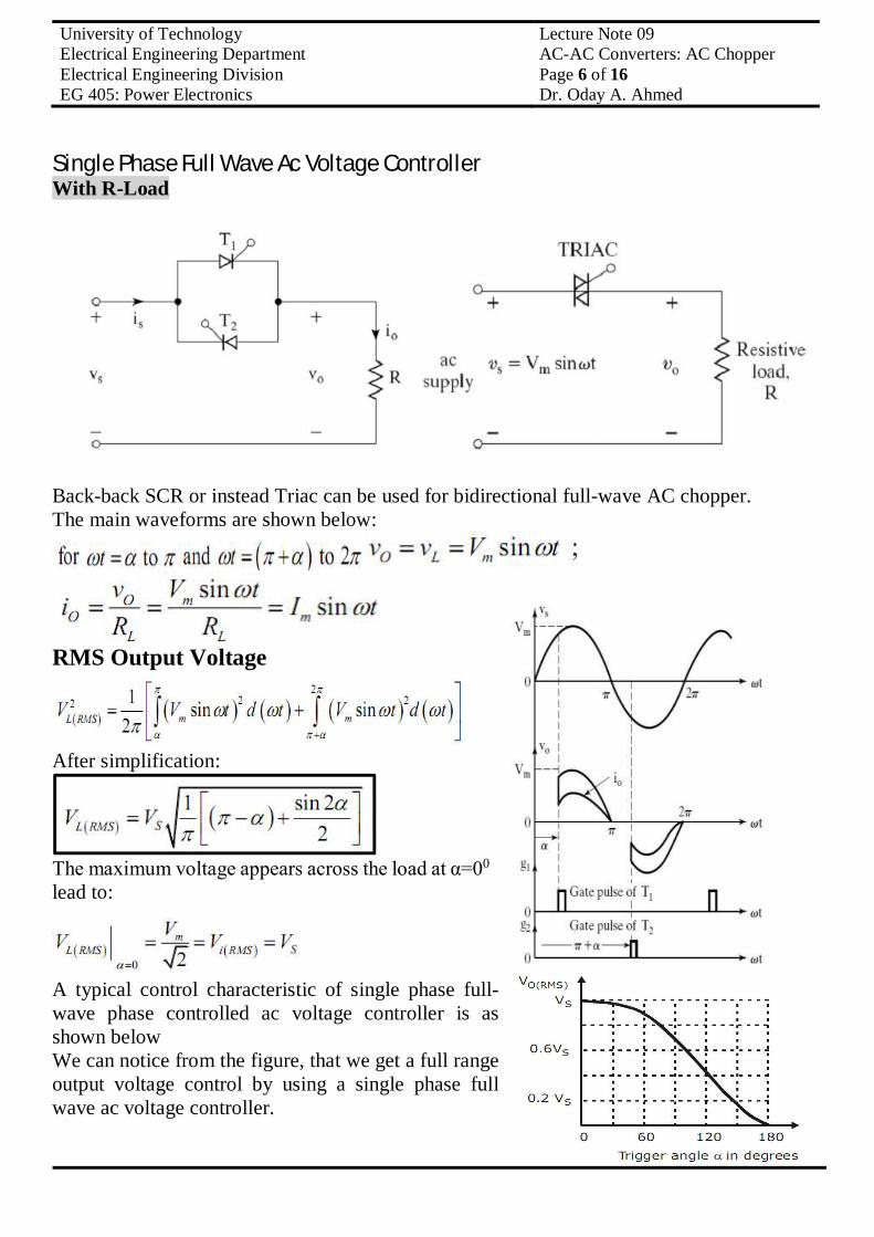
Single Phase Full Wave Ac Voltage Controller With R-Load
Back-back SCR or instead Triac can be used for bidirectional full-wave AC chopper. The main waveforms are shown below:
RMS Output Voltage
After simplification:
The maximum voltage appears across the load at α=00 lead to:
A typical control characteristic of single phase full-wave phase controlled ac voltage controller is as shown below We can notice from the figure, that we get a full range output voltage control by using a single phase full wave ac voltage controller.
University of Technology Lecture Note 09 Electrical Engineering Department AC-AC Converters: AC Chopper Electrical Engineering Division Page 7 of 16 EG 405: Power Electronics Dr. Oday A. Ahmed
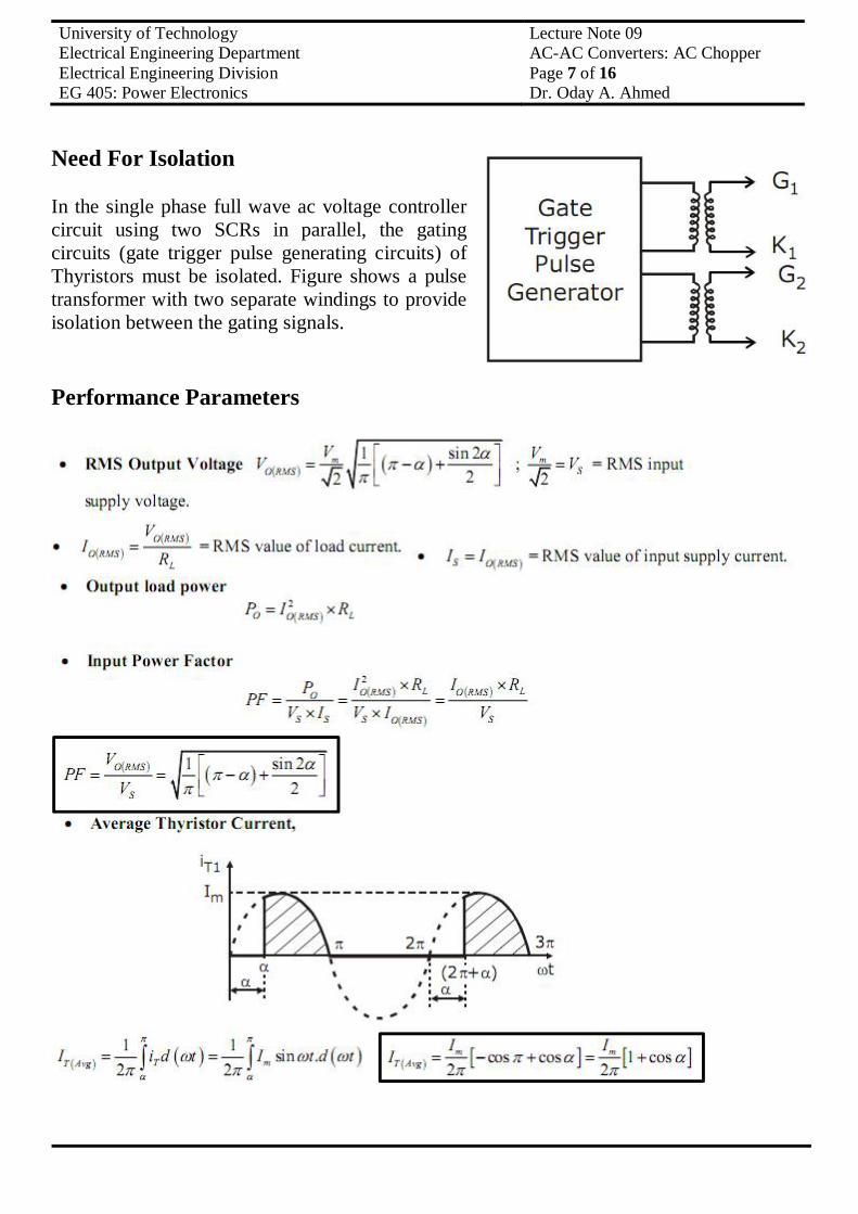
Need For Isolation In the single phase full wave ac voltage controller circuit using two SCRs in parallel, the gating circuits (gate trigger pulse generating circuits) of Thyristors must be isolated. Figure shows a pulse transformer with two separate windings to provide isolation between the gating signals. Performance Parameters
University of Technology Lecture Note 09 Electrical Engineering Department AC-AC Converters: AC Chopper Electrical Engineering Division Page 8 of 16 EG 405: Power Electronics Dr. Oday A. Ahmed
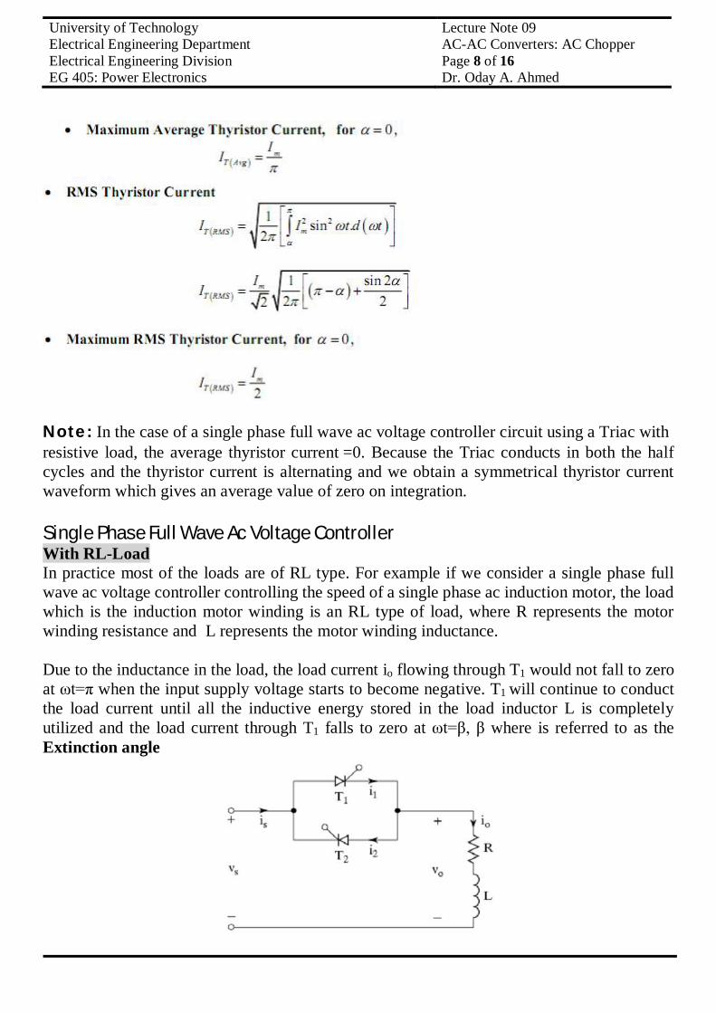
Note: In the case of a single phase full wave ac voltage controller circuit using a Triac with resistive load, the average thyristor current =0. Because the Triac conducts in both the half cycles and the thyristor current is alternating and we obtain a symmetrical thyristor current waveform which gives an average value of zero on integration. Single Phase Full Wave Ac Voltage Controller With RL-Load In practice most of the loads are of RL type. For example if we consider a single phase full wave ac voltage controller controlling the speed of a single phase ac induction motor, the load which is the induction motor winding is an RL type of load, where R represents the motor winding resistance and L represents the motor winding inductance. Due to the inductance in the load, the load current io flowing through T1 would not fall to zero at ωt=π when the input supply voltage starts to become negative. T1 will continue to conduct the load current until all the inductive energy stored in the load inductor L is completely utilized and the load current through T1 falls to zero at ωt=β, β where is referred to as the Extinction angle
University of Technology Lecture Note 09 Electrical Engineering Department AC-AC Converters: AC Chopper Electrical Engineering Division Page 9 of 16 EG 405: Power Electronics Dr. Oday A. Ahmed
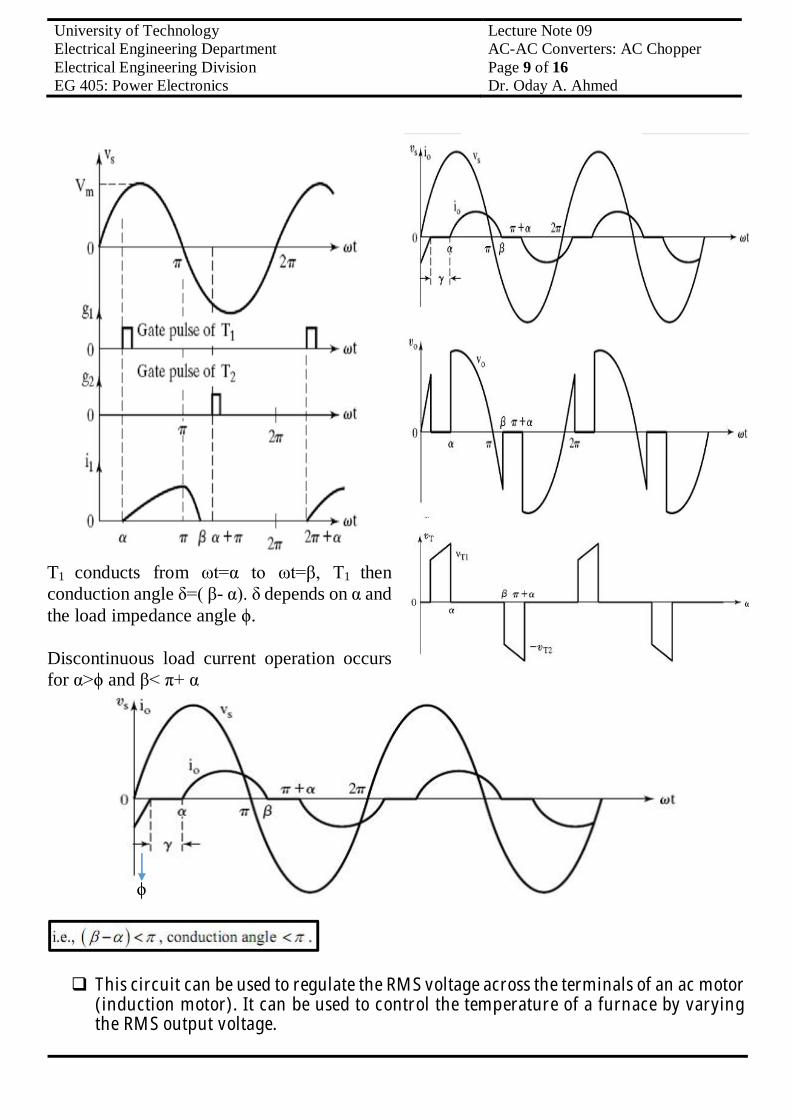
T1 conducts from ωt=α to ωt=β, T1 then conduction angle δ=( β- α). δ depends on α and the load impedance angle ϕ. Discontinuous load current operation occurs for α>ϕ and β< π+ α
This circuit can be used to regulate the RMS voltage across the terminals of an ac motor
(induction motor). It can be used to control the temperature of a furnace by varying the RMS output voltage.
ϕ
University of Technology Lecture Note 09 Electrical Engineering Department AC-AC Converters: AC Chopper Electrical Engineering Division Page 10 of 16 EG 405: Power Electronics Dr. Oday A. Ahmed
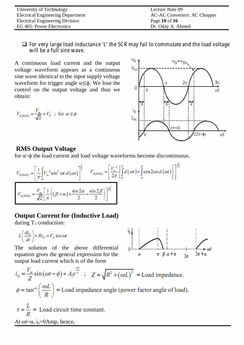
For very large load inductance ‘L’ the SCR may fail to commutate and the load voltage will be a full sine wave.
A continuous load current and the output voltage waveform appears as a continuous sine wave identical to the input supply voltage waveform for trigger angle α≤ϕ. We lose the control on the output voltage and thus we obtain:
RMS Output Voltage for α>ϕ the load current and load voltage waveforms become discontinuous.
Output Current for (Inductive Load) during T1 conduction:
The solution of the above differential equation gives the general expression for the output load current which is of the form
At ωt=α, io=0Amp, hence,
University of Technology Lecture Note 09 Electrical Engineering Department AC-AC Converters: AC Chopper Electrical Engineering Division Page 11 of 16 EG 405: Power Electronics Dr. Oday A. Ahmed
By substituting ωt=α: then,
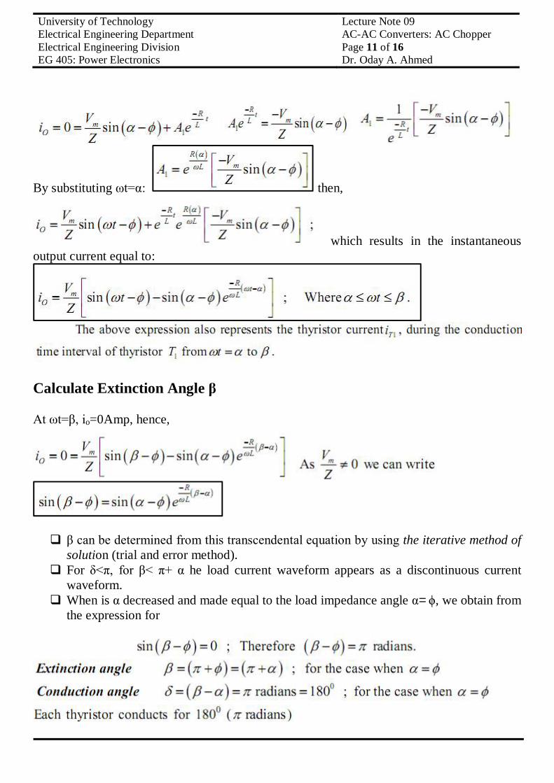
which results in the instantaneous output current equal to:
Calculate Extinction Angle β At ωt=β, io=0Amp, hence,
β can be determined from this transcendental equation by using the iterative method of
solution (trial and error method). For δ<π, for β< π+ α he load current waveform appears as a discontinuous current
waveform. When is α decreased and made equal to the load impedance angle α=ϕ, we obtain from
the expression for
University of Technology Lecture Note 09 Electrical Engineering Department AC-AC Converters: AC Chopper Electrical Engineering Division Page 12 of 16 EG 405: Power Electronics Dr. Oday A. Ahmed
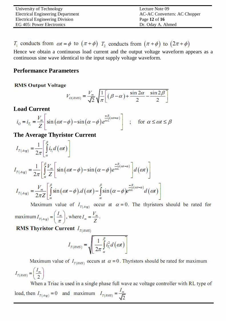
Hence we obtain a continuous load current and the output voltage waveform appears as a continuous sine wave identical to the input supply voltage waveform. Performance Parameters
Load Current
The Average Thyristor Current
University of Technology Lecture Note 09 Electrical Engineering Department AC-AC Converters: AC Chopper Electrical Engineering Division Page 13 of 16 EG 405: Power Electronics Dr. Oday A. Ahmed
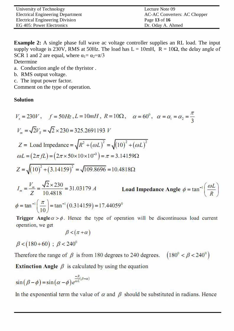
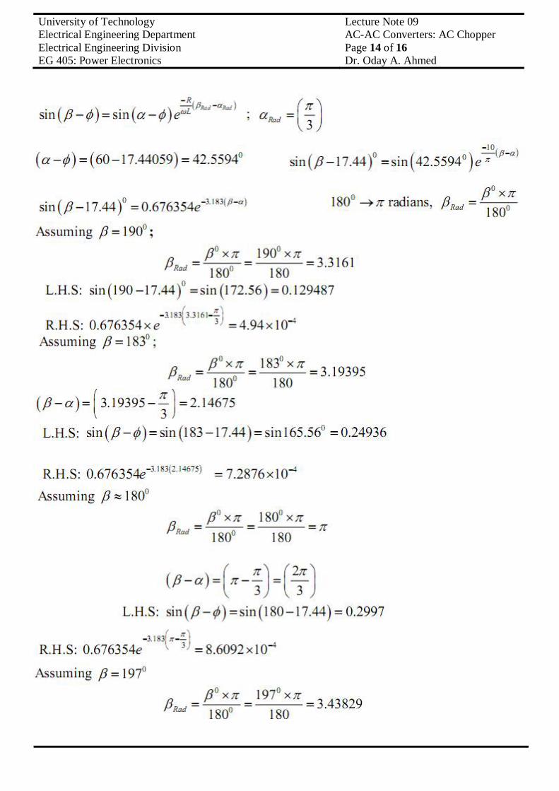
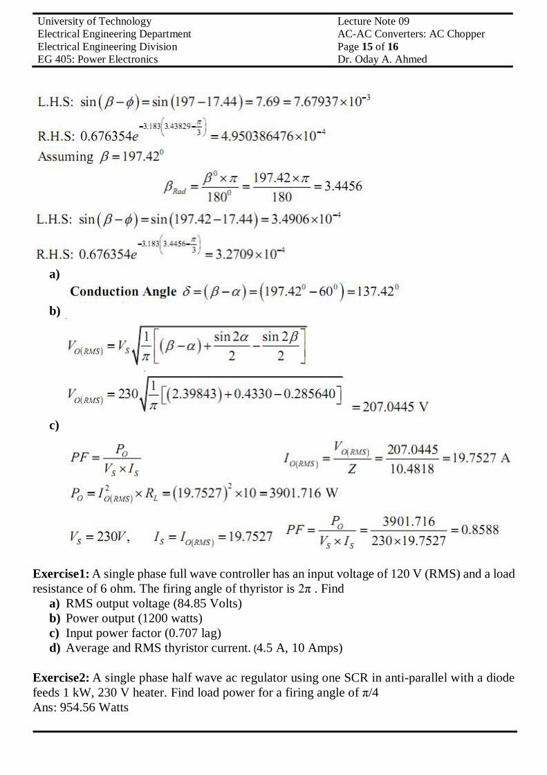
Example 2: A single phase full wave ac voltage controller supplies an RL load. The input supply voltage is 230V, RMS at 50Hz. The load has L = 10mH, R = 10Ω, the delay angle of SCR 1 and 2 are equal, where α1= α2=π/3 Determine a. Conduction angle of the thyristor . b. RMS output voltage. c. The input power factor. Comment on the type of operation. Solution
University of Technology Lecture Note 09 Electrical Engineering Department AC-AC Converters: AC Chopper Electrical Engineering Division Page 14 of 16 EG 405: Power Electronics Dr. Oday A. Ahmed
University of Technology Lecture Note 09 Electrical Engineering Department AC-AC Converters: AC Chopper Electrical Engineering Division Page 15 of 16 EG 405: Power Electronics Dr. Oday A. Ahmed
a)
b)
c)
Exercise1: A single phase full wave controller has an input voltage of 120 V (RMS) and a load resistance of 6 ohm. The firing angle of thyristor is 2π . Find
a) RMS output voltage (84.85 Volts) b) Power output (1200 watts) c) Input power factor (0.707 lag) d) Average and RMS thyristor current. (4.5 A, 10 Amps)
Exercise2: A single phase half wave ac regulator using one SCR in anti-parallel with a diode feeds 1 kW, 230 V heater. Find load power for a firing angle of π/4 Ans: 954.56 Watts
University of Technology Lecture Note 09 Electrical Engineering Department AC-AC Converters: AC Chopper Electrical Engineering Division Page 16 of 16 EG 405: Power Electronics Dr. Oday A. Ahmed
Exercise3: A single phase voltage controller is employed for controlling the power flow from 220 V, 50 Hz source into a load circuit consisting of R = 4 Ω and L = 6 mH. Calculate the following
a. Control range of firing angle b. Maximum value of RMS load current 30.5085 Amps c. Maximum power and power factor 3723.077 W, 0.5547 d. Maximum value of average and RMS thyristor current. 13.7336 Amps, 21.57277 Amps Self-assessments:
a) What phase angle control is as applied to single phase controllers? Highlight the advantages and disadvantages of such a method of control. Draw all the wave forms.
b) What are unidirectional controllers? Explain the operation of the same with the help of waveforms and obtain the expression for the RMS value of the output voltage. What are the advantage and disadvantages of unidirectional controllers?