Embed Size (px)
Citation preview
ABZ Encoder Sensor
1
NVE Corporation 11409 Valley View Road, Eden Prairie, MN 55344 (952) 829-9217 www.nve.com YouTube.com/NveCorporation [email protected]
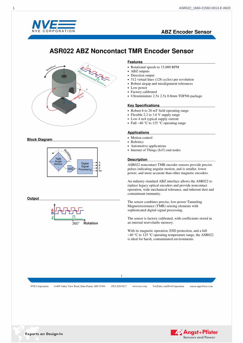
ASR022 ABZ Noncontact TMR Encoder Sensor
Block Diagram
DigitalSignal
Processing
TMRSensorAngle A
BZDir
ADC
Output
360° Rotation
AB
Z
Features
• Rotational speeds to 15,000 RPM
• ABZ outputs
• Direction output
• 512 virtual lines (128 cycles) per revolution
• Robust airgap and misalignment tolerances
• Low power
• Factory calibrated
• Ultraminiature 2.5x 2.5x 0.8mm TDFN6 package
Key Specifications
• Robust 6 to 20 mT field operating range
• Flexible 2.2 to 3.6 V supply range
• Low 4 mA typical supply current
• Full −40 °C to 125 °C operating range
Applications
• Motion control
• Robotics
• Automotive applications
• Internet of Things (IoT) end nodes
Description
ASR022 noncontact TMR encoder sensors provide precise
pulses indicating angular motion, and is smaller, lower
power, and more accurate than other magnetic encoders.
An industry-standard ABZ interface allows the ASR022 to
replace legacy optical encoders and provide noncontact
operation, wide mechanical tolerance, and inherent dust and
contaminant immunity.
The sensor combines precise, low-power Tunneling
Magnetoresistance (TMR) sensing elements with
sophisticated digital signal processing.
The sensor is factory calibrated, with coefficients stored in
an internal nonvolatile memory.
With its magnetic operation, ESD protection, and a full
−40 °C to 125 °C operating temperature range, the ASR022
is ideal for harsh, contaminated environments.
1 ASR022_1660-21592-0013-E-0620

ABZ Encoder Sensor
2
NVE Corporation 11409 Valley View Road, Eden Prairie, MN 55344 (952) 829-9217 www.nve.com YouTube.com/NveCorporation [email protected]
Boundary Ratings
Parameter Min. Max. Units
Supply voltage −12 4.2 Volts
Storage temperature −55 150 °C
ESD (Human Body Model) 2000 Volts
Applied magnetic field
Unlimited Tesla
2 ASR022_1660-21592-0013-E-0620
ABZ Encoder Sensor
3
NVE Corporation 11409 Valley View Road, Eden Prairie, MN 55344 (952) 829-9217 www.nve.com YouTube.com/NveCorporation [email protected]
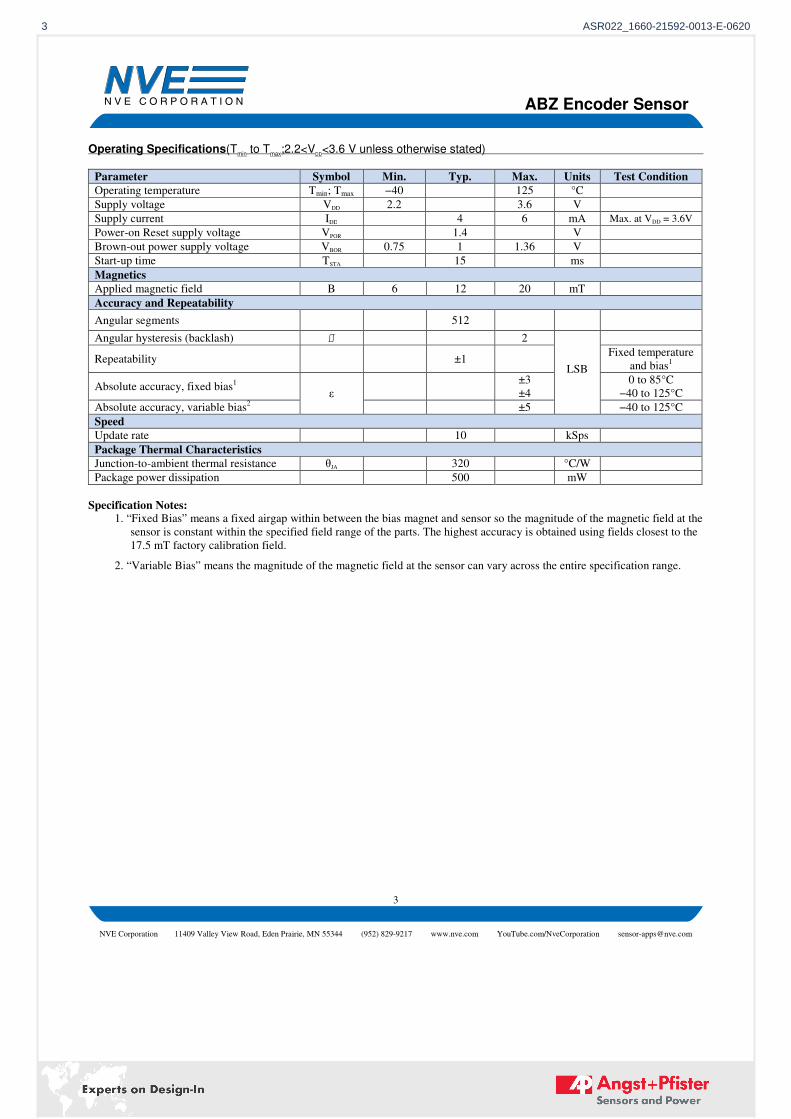
Operating Specifications(Tmin
to Tmax
;2.2<VDD
<3.6 V unless otherwise stated)
Parameter Symbol Min. Typ. Max. Units Test Condition
Operating temperature
Tmin; Tmax −40 125 °C
Supply voltage VDD 2.2 3.6 V
Supply current IDD 4 6 mA
Max. at VDD = 3.6V
Power-on Reset supply voltage VPOR 1.4 V
Brown-out power supply voltage VBOR 0.75 1 1.36 V
Start-up time TSTA 15 ms
Magnetics
Applied magnetic field B 6 12 20 mT
Accuracy and Repeatability
Angular segments 512
Angular hysteresis (backlash) ⎎ 2
LSB
Repeatability ±1 Fixed temperature
and bias1
Absolute accuracy, fixed bias1
ε
±3
±4
0 to 85°C
−40 to 125°C
Absolute accuracy, variable bias2 ±5 −40 to 125°C
Speed
Update rate 10 kSps
Package Thermal Characteristics
Junction-to-ambient thermal resistance θJA 320 °C/W
Package power dissipation 500 mW
Specification Notes: 1. “Fixed Bias” means a fixed airgap within between the bias magnet and sensor so the magnitude of the magnetic field at the
sensor is constant within the specified field range of the parts. The highest accuracy is obtained using fields closest to the
17.5 mT factory calibration field. 2. “Variable Bias” means the magnitude of the magnetic field at the sensor can vary across the entire specification range.
3 ASR022_1660-21592-0013-E-0620
ABZ Encoder Sensor
4
NVE Corporation 11409 Valley View Road, Eden Prairie, MN 55344 (952) 829-9217 www.nve.com YouTube.com/NveCorporation [email protected]
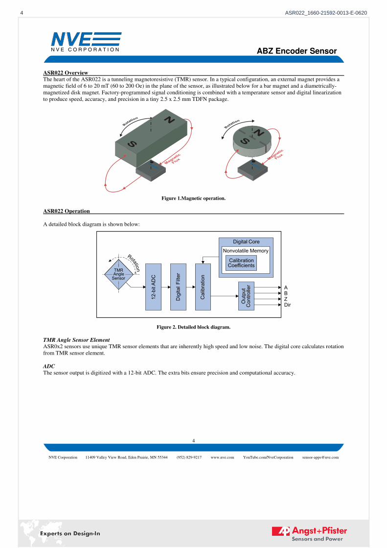
ASR022 Overview
The heart of the ASR022 is a tunneling magnetoresistive (TMR) sensor. In a typical configuration, an external magnet provides a
magnetic field of 6 to 20 mT (60 to 200 Oe) in the plane of the sensor, as illustrated below for a bar magnet and a diametrically-
magnetized disk magnet. Factory-programmed signal conditioning is combined with a temperature sensor and digital linearization
to produce speed, accuracy, and precision in a tiny 2.5 x 2.5 mm TDFN package.
Figure 1.Magnetic operation.
ASR022 Operation
A detailed block diagram is shown below:
Digital F
ilter
Calibration
12-bitA
DC
Nonvolatile MemoryDigital Core
CalibrationCoefficients
TMRSensorAngle
ABZDirCo
ntroller
Output
Figure 2. Detailed block diagram.
TMR Angle Sensor Element
ASR0x2 sensors use unique TMR sensor elements that are inherently high speed and low noise. The digital core calculates rotation
from TMR sensor element.
ADC
The sensor output is digitized with a 12-bit ADC. The extra bits ensure precision and computational accuracy.
4 ASR022_1660-21592-0013-E-0620
ABZ Encoder Sensor
5
NVE Corporation 11409 Valley View Road, Eden Prairie, MN 55344 (952) 829-9217 www.nve.com YouTube.com/NveCorporation [email protected]
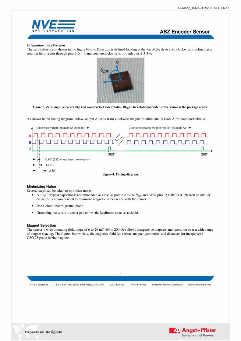
Orientation and Direction
The zero reference is shown in the figure below. Direction is defined looking at the top of the device, so clockwise is defined as a
rotating field vector through pins 1-6-4-3 and counterclockwise is through pins 1-3-4-6.
Figure 3. Zero-angle reference (θ0) and counterclockwise rotation (θDIR).The rotational center of the sensor is the package center.
As shown in the timing diagram, below, output A leads B for clockwise magnet rotation, and B leads A for counterclockwise:
Figure 4. Timing diagram.
Minimizing Noise Several steps can be taken to minimize noise:
• A 10 µF bypass capacitor is recommended as close as possible to the VDD and GND pins. A 0.080 x 0.050 inch or smaller
capacitor is recommended to minimize magnetic interference with the sensor.
• Use a circuit board ground plane.
• Grounding the sensor’s center pad allows the leadframe to act as a shield.
Magnet Selection The sensor’s wide operating field range of 6 to 20 mT (60 to 200 Oe) allows inexpensive magnets and operation over a wide range
of magnet spacing. The figures below show the magnetic field for various magnet geometries and distances for inexpensive
C5/Y25 grade ferrite magnets:
360°
A
B
Z
0.70° (512 virtual lines / revolution)
Clockwise magnet rotation ( )A leads B Counterclockwise magnet rotation (B leads A)
1.40°
2.80°
360°
5 ASR022_1660-21592-0013-E-0620
ABZ Encoder Sensor
6
NVE Corporation 11409 Valley View Road, Eden Prairie, MN 55344 (952) 829-9217 www.nve.com YouTube.com/NveCorporation [email protected]
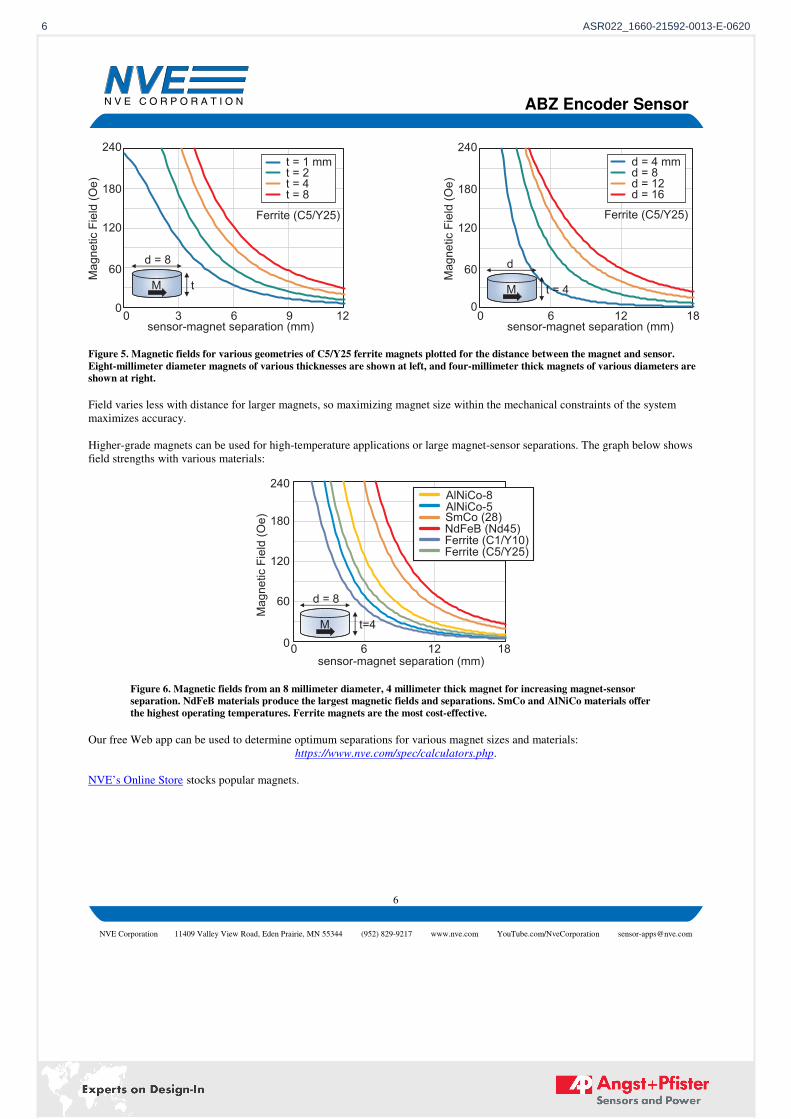
Figure 5. Magnetic fields for various geometries of C5/Y25 ferrite magnets plotted for the distance between the magnet and sensor.
Eight-millimeter diameter magnets of various thicknesses are shown at left, and four-millimeter thick magnets of various diameters are
shown at right.
Field varies less with distance for larger magnets, so maximizing magnet size within the mechanical constraints of the system
maximizes accuracy.
Higher-grade magnets can be used for high-temperature applications or large magnet-sensor separations. The graph below shows
field strengths with various materials:
Figure 6. Magnetic fields from an 8 millimeter diameter, 4 millimeter thick magnet for increasing magnet-sensor
separation. NdFeB materials produce the largest magnetic fields and separations. SmCo and AlNiCo materials offer
the highest operating temperatures. Ferrite magnets are the most cost-effective.
Our free Web app can be used to determine optimum separations for various magnet sizes and materials:
https://www.nve.com/spec/calculators.php.
NVE’s Online Store stocks popular magnets.
240
180
120
0
60
Ma
gn
etic F
ield
(O
e)
0 3 6 9 12sensor-magnet separation (mm)
0 6 12 18sensor-magnet separation (mm)
t = 2t = 4t = 8
t = 1 mmd = 8d = 12d = 16
d = 4 mm
240
180
120
0
60
Ma
gn
etic F
ield
(O
e)
Ferrite (C5/Y25) Ferrite (C5/Y25)
d = 8
tM
d
t = 4M
240
180
120
0
60
Ma
gn
etic
Fie
ld(O
e)
0 6 12 18sensor-magnet separation (mm)
AlNiCo-8AlNiCo-5SmCo (28)NdFeB (Nd45)Ferrite (C1/Y10)Ferrite (C5/Y25)
d = 8
t=4M
6 ASR022_1660-21592-0013-E-0620

ABZ Encoder Sensor
7
NVE Corporation 11409 Valley View Road, Eden Prairie, MN 55344 (952) 829-9217 www.nve.com YouTube.com/NveCorporation [email protected]
Application Circuits
Isolated Microcontroller Interface
Double isolation from human interface to line-voltage driven electrical circuitry is required in some safety intensive applications
such as medical instruments. The mechanical gap between the magnet and the sensor can provide one level of isolation. Galvanic
isolation from the sensor to the microcontroller provides a second isolation barrier. The IL715 isolator in the circuit above is rated
at 2.5 kV isolation, is UL/VDE-compliant, and is available in an ultra-miniature QSOP package. The isolator can also level-shift
between the 3.3-volt sensor and a five-volt microcontroller:
A
GND1
VDD1 VDD2
GND2
ASR022-10E Microcontroller
GPIO
GPIO
3.3 V
IL710V-
1E
Iso
lati
on
Barrie
r
3 - 5 V
1 Fµ
IL715
B
GPIOZ
GPIODIR
Figure 7. Isolated microcontroller interface.
7 ASR022_1660-21592-0013-E-0620
ABZ Encoder Sensor
8
NVE Corporation 11409 Valley View Road, Eden Prairie, MN 55344 (952) 829-9217 www.nve.com YouTube.com/NveCorporation [email protected]
Evaluation Support
Breakout Board
The AG957-07E breakout board provides easy connections to an ASR022-10E angle sensor with a six pin connector. It also has a
recommended 10 µF bypass capacitor:
NVE
Figure 8. ASR0x2 breakout board (actual size) 0.5" x 0.6" (12 mm x 15 mm)
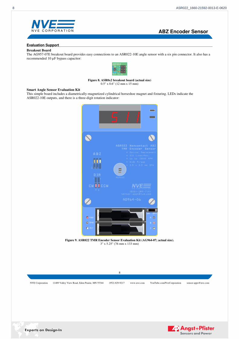
Smart Angle Sensor Evaluation Kit
This simple board includes a diametrically-magnetized cylindrical horseshoe magnet and fixturing. LEDs indicate the
ASR022-10E outputs, and there is a three-digit rotation indicator:
Figure 9. ASR022 TMR Encoder Sensor Evaluation Kit (AG964-07; actual size). 3" x 5.25" (76 mm x 133 mm)
8 ASR022_1660-21592-0013-E-0620
ABZ Encoder Sensor
9
NVE Corporation 11409 Valley View Road, Eden Prairie, MN 55344 (952) 829-9217 www.nve.com YouTube.com/NveCorporation [email protected]
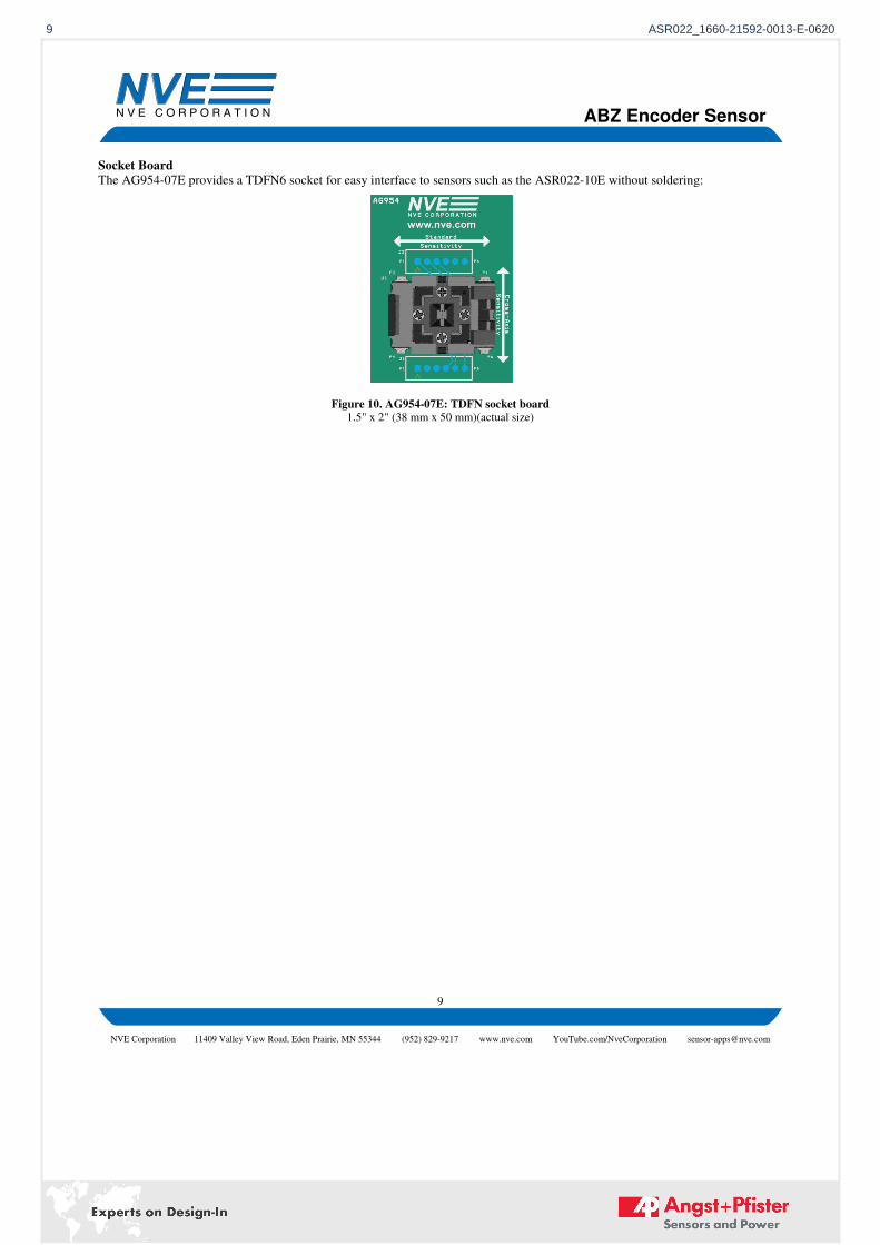
Socket Board
The AG954-07E provides a TDFN6 socket for easy interface to sensors such as the ASR022-10E without soldering:
Figure 10. AG954-07E: TDFN socket board 1.5" x 2" (38 mm x 50 mm)(actual size)
9 ASR022_1660-21592-0013-E-0620
ABZ Encoder Sensor
10
NVE Corporation 11409 Valley View Road, Eden Prairie, MN 55344 (952) 829-9217 www.nve.com YouTube.com/NveCorporation [email protected]
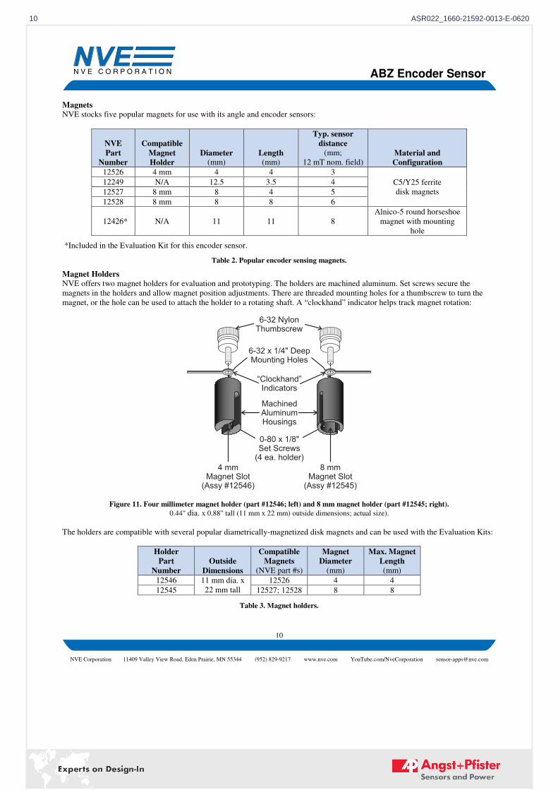
Magnets
NVE stocks five popular magnets for use with its angle and encoder sensors:
NVE
Part
Number
Compatible
Magnet
Holder
Diameter (mm)
Length (mm)
Typ. sensor
distance
(mm;
12 mT nom. field) Material and
Configuration
12526 4 mm 4 4 3
C5/Y25 ferrite
disk magnets
12249 N/A 12.5 3.5 4
12527 8 mm 8 4 5
12528 8 mm 8 8 6
12426* N/A 11 11 8
Alnico-5 round horseshoe
magnet with mounting
hole
*Included in the Evaluation Kit for this encoder sensor.
Table 2. Popular encoder sensing magnets.
Magnet Holders
NVE offers two magnet holders for evaluation and prototyping. The holders are machined aluminum. Set screws secure the
magnets in the holders and allow magnet position adjustments. There are threaded mounting holes for a thumbscrew to turn the
magnet, or the hole can be used to attach the holder to a rotating shaft. A “clockhand” indicator helps track magnet rotation:
6-32 x 1/4" DeepMounting Holes
0-80 x 1/8"Set Screws
(4 ea. holder)
8 mmMagnet Slot
(Assy # )12545
4 mmMagnet Slot
(Assy # )12546
6-32 NylonThumbscrew
“Clockhand”
Indicators
MachinedAluminumHousings
Figure 11. Four millimeter magnet holder (part #12546; left) and 8 mm magnet holder (part #12545; right).
0.44" dia. x 0.88" tall (11 mm x 22 mm) outside dimensions; actual size).
The holders are compatible with several popular diametrically-magnetized disk magnets and can be used with the Evaluation Kits:
Holder
Part
Number
Outside
Dimensions
Compatible
Magnets
(NVE part #s)
Magnet
Diameter
(mm)
Max. Magnet
Length
(mm)
12546 11 mm dia. x
22 mm tall
12526 4 4
12545 12527; 12528 8 8
Table 3. Magnet holders.
10 ASR022_1660-21592-0013-E-0620
ABZ Encoder Sensor
11
NVE Corporation 11409 Valley View Road, Eden Prairie, MN 55344 (952) 829-9217 www.nve.com YouTube.com/NveCorporation [email protected]
RoHS
COMPLIANT
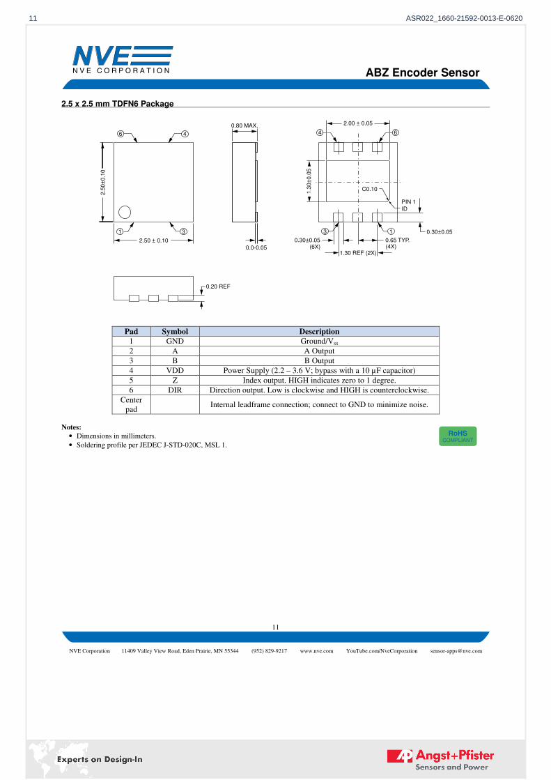
2.5 x 2.5 mm TDFN6 Package
Pad Symbol Description
1 GND Ground/VSS
2 A A Output
3 B B Output
4 VDD Power Supply (2.2 – 3.6 V; bypass with a 10 µF capacitor)
5 Z Index output. HIGH indicates zero to 1 degree.
6 DIR Direction output. Low is clockwise and HIGH is counterclockwise.
Center
pad Internal leadframe connection; connect to GND to minimize noise.
Notes:
• Dimensions in millimeters.
• Soldering profile per JEDEC J-STD-020C, MSL 1.
2.00 ± 0.05
C0.10
PIN 1
0.30±0.05
0.30±0.05 0.65 TYP.
1.30 REF (2X)
131 3
644
2.50 ± 0.10
2.5
0±
0.1
0
6
0.0-0.05
0.80 MAX.
0.20 REF
1.3
0±
0.0
5
ID
(6X) (4X)
11 ASR022_1660-21592-0013-E-0620
ABZ Encoder Sensor
12
NVE Corporation 11409 Valley View Road, Eden Prairie, MN 55344 (952) 829-9217 www.nve.com YouTube.com/NveCorporation [email protected]
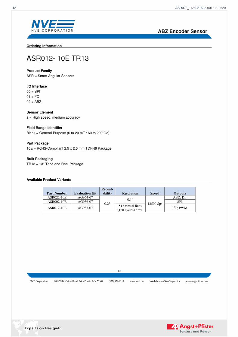
Ordering Information
ASR012- 10E TR13
Product Family
ASR = Smart Angular Sensors
I/O Interface
00 = SPI
01 = I²C
02 = ABZ
Sensor Element
2 = High speed, medium accuracy
Field Range Identifier
Blank = General Purpose (6 to 20 mT / 60 to 200 Oe)
Part Package
10E = RoHS-Compliant 2.5 x 2.5 mm TDFN6 Package
Bulk Packaging
TR13 = 13'' Tape and Reel Package
Available Product Variants
Part Number Evaluation Kit Repeat-
ability Resolution Speed Outputs ASR022-10E AG964-07
0.2°
0.1°
12500 Sps
ABZ; Dir
ASR002-10E AG956-07 SPI
ASR012-10E AG963-07 512 virtual lines
(128 cycles) / rev. I
2C; PWM
12 ASR022_1660-21592-0013-E-0620
ABZ Encoder Sensor
13
NVE Corporation 11409 Valley View Road, Eden Prairie, MN 55344 (952) 829-9217 www.nve.com YouTube.com/NveCorporation [email protected]
Revision History
SB-00-119-A April 2020
Changes
• Added demonstration board.
• Revised some graphics.
• Initial release.
SB-00-119-PRELIM March 2020
Change
• Preliminary release.
13 ASR022_1660-21592-0013-E-0620
ABZ Encoder Sensor
14
NVE Corporation 11409 Valley View Road, Eden Prairie, MN 55344 (952) 829-9217 www.nve.com YouTube.com/NveCorporation [email protected]
Datasheet Limitations
The information and data provided in datasheets shall define the specification of the product as agreed between NVE and its customer, unless NVE and
customer have explicitly agreed otherwise in writing. All specifications are based on NVE test protocols. In no event however, shall an agreement be
valid in which the NVE product is deemed to offer functions and qualities beyond those described in the datasheet.
Limited Warranty and Liability
Information in this document is believed to be accurate and reliable. However, NVE does not give any representations or warranties, expressed or
implied, as to the accuracy or completeness of such information and shall have no liability for the consequences of use of such information.
In no event shall NVE be liable for any indirect, incidental, punitive, special or consequential damages (including, without limitation, lost profits, lost
savings, business interruption, costs related to the removal or replacement of any products or rework charges) whether or not such damages are based on
tort (including negligence), warranty, breach of contract or any other legal theory.
Right to Make Changes
NVE reserves the right to make changes to information published in this document including, without limitation, specifications and product descriptions
at any time and without notice. This document supersedes and replaces all information supplied prior to its publication.
Use in Life-Critical or Safety-Critical Applications Unless NVE and a customer explicitly agree otherwise in writing, NVE products are not designed, authorized or warranted to be suitable for use in life
support, life-critical or safety-critical devices or equipment. NVE accepts no liability for inclusion or use of NVE products in such applications and such
inclusion or use is at the customer’s own risk. Should the customer use NVE products for such application whether authorized by NVE or not, the
customer shall indemnify and hold NVE harmless against all claims and damages.
Applications Applications described in this datasheet are illustrative only. NVE makes no representation or warranty that such applications will be suitable for the
specified use without further testing or modification.
Customers are responsible for the design and operation of their applications and products using NVE products, and NVE accepts no liability for any
assistance with applications or customer product design. It is customer’s sole responsibility to determine whether the NVE product is suitable and fit for
the customer’s applications and products planned, as well as for the planned application and use of customer’s third party customers. Customers should
provide appropriate design and operating safeguards to minimize the risks associated with their applications and products.
NVE does not accept any liability related to any default, damage, costs or problem which is based on any weakness or default in the customer’s
applications or products, or the application or use by customer’s third party customers. The customer is responsible for all necessary testing for the
customer’s applications and products using NVE products in order to avoid a default of the applications and the products or of the application or use by
customer’s third party customers. NVE accepts no liability in this respect.
Limiting Values Stress above one or more limiting values (as defined in the Absolute Maximum Ratings System of IEC 60134) will cause permanent damage to the
device. Limiting values are stress ratings only and operation of the device at these or any other conditions above those given in the recommended
operating conditions of the datasheet is not warranted. Constant or repeated exposure to limiting values will permanently and irreversibly affect the
quality and reliability of the device.
Terms and Conditions of Sale In case an individual agreement is concluded only the terms and conditions of the respective agreement shall apply. NVE hereby expressly objects to
applying the customer’s general terms and conditions with regard to the purchase of NVE products by customer.
No Offer to Sell or License
Nothing in this document may be interpreted or construed as an offer to sell products that is open for acceptance or the grant, conveyance or implication
of any license under any copyrights, patents or other industrial or intellectual property rights.
Export Control
This document as well as the items described herein may be subject to export control regulations. Export might require a prior authorization from national authorities.
Automotive Qualified Products Unless the datasheet expressly states that a specific NVE product is automotive qualified, the product is not suitable for automotive use. It is neither
qualified nor tested in accordance with automotive testing or application requirements. NVE accepts no liability for inclusion or use of non-automotive
qualified products in automotive equipment or applications.
In the event that customer uses the product for design-in and use in automotive applications to automotive specifications and standards, customer (a) shall
use the product without NVE’s warranty of the product for such automotive applications, use and specifications, and (b) whenever customer uses the
product for automotive applications beyond NVE’s specifications such use shall be solely at customer’s own risk, and (c) customer fully indemnifies
NVE for any liability, damages or failed product claims resulting from customer design and use of the product for automotive applications beyond NVE’s
standard warranty and NVE’s product specifications.
14 ASR022_1660-21592-0013-E-0620
ABZ Encoder Sensor
15
NVE Corporation 11409 Valley View Road, Eden Prairie, MN 55344 (952) 829-9217 www.nve.com YouTube.com/NveCorporation [email protected]
An ISO 9001 Certified Company
NVE Corporation
11409 Valley View Road
Eden Prairie, MN 55344-3617 USA
Telephone: (952) 829-9217
www.nve.com
e-mail: [email protected]
©NVE Corporation
All rights are reserved. Reproduction in whole or in part is prohibited without the prior written consent of the copyright owner.
SB-00-119_ASR022-10_RevA
April 2020
15 ASR022_1660-21592-0013-E-0620

Experts on Design-Infor sensors and power solutions
Scan here and get an overview of personal contacts!
sensorsandpower.angst-pfister.com
We are here for you. Addresses and Contacts.
Headquarter Switzerland:
Angst+Pfister Sensors and Power AG
Thurgauerstrasse 66CH-8050 Zurich
Phone +41 44 877 35 [email protected]
Office Germany:
Angst+Pfister Sensors and Power Deutschland GmbH
Edisonstraße 16D-85716 Unterschleißheim
Phone +49 89 374 288 87 [email protected]