Embed Size (px)
Citation preview

i
Abstract
The goal of this project was to analyze, design and implement an autonomous quadrotor
aerial vehicle for collaborative operations with autonomous ground vehicles. The main design
constraints were to maximize payload and flight time. The quadrotor consists of a Delrin hub
with four aluminum arms, and is infused with an IMU and multiple range finder sensors. All of
the electronics on the quadrotor were implemented and the equations of motion were derived,
however at the time this report was written the control equations were not yet programmed. The
ground robot is also currently unable to communicate with the quadrotor despite the
communication framework being set in place. However, further work programming both the
quadrotor and the ground robot could result in a fully-functional system.

ii
Table of Contents Abstract ............................................................................................................................................ i
List of Figures ................................................................................................................................. iv
List of Tables ................................................................................................................................... v
1. Introduction ............................................................................................................................. 1
2. History ..................................................................................................................................... 2
3. Goals and Methodology........................................................................................................... 5
4. Rotor Dynamics ....................................................................................................................... 6
4.1 Basic Equations ................................................................................................................. 6
4.2 Deriving the Propeller Thrust Equation ........................................................................... 8
4.3 Propeller Wake ............................................................................................................... 10
5. Mechanical Design ................................................................................................................ 10
5.1 Design Considerations .................................................................................................... 11
5.2 Material Selection .......................................................................................................... 12
5.3 Prototype ........................................................................................................................ 13
5.4 Motor Alignment ............................................................................................................ 14
5.5 Propeller Selection ......................................................................................................... 14
5.6 Vibration Analysis ........................................................................................................... 15
5.7 Landing Pad .................................................................................................................... 17
6. Quadrotor Control.................................................................................................................. 18
6.1 Dynamics of Motion ....................................................................................................... 19
6.2 Altitude Control .............................................................................................................. 22
6.3 Yaw Control .................................................................................................................... 23
6.4 Pitch and Roll Control ..................................................................................................... 24
6.5 MATLAB Simulation ........................................................................................................ 25
6.6 Speed and Motor Control............................................................................................... 27
7. Electrical System ................................................................................................................... 28
7.1 Processing ....................................................................................................................... 28
7.2 Motor Control ................................................................................................................ 31
7.3 Telemetry ....................................................................................................................... 33
iii
7.4 Inertial Measurement .................................................................................................... 34
7.5 Active Sensing ................................................................................................................ 35
7.6 Battery ............................................................................................................................ 37
7.7 Ground Robot ................................................................................................................. 38
8. Programming ......................................................................................................................... 39
8.1 Quadrotor Programming ................................................................................................ 40
8.2 Ground Robot Programming .......................................................................................... 44
9. Test Setups ............................................................................................................................. 45
9.1 Vertical Thrust Test Stand .............................................................................................. 48
9.2 Sensor Testing ................................................................................................................ 49
10. Timeline ............................................................................................................................. 51
11. Final Results....................................................................................................................... 52
12. Reflections of Project ......................................................................................................... 53
Bibliography ................................................................................................................................. 56
Appendices .................................................................................................................................... 57
Appendix A: Table of Electronics ............................................................................................... 57
Appendix B: MATLAB Code ....................................................................................................... 58
iv
List of Figures
Figure 1-1: The Quadrotor (1) ........................................................................................................ 1
Figure 2-1: Oemichen‟s No. 2 Design (3) ...................................................................................... 3
Figure 2-2: Bothezat's Design (4) ................................................................................................... 4
Figure 3-1: Final implementation of the quadrotor. ........................................................................ 5
Figure 4-1: Propeller Wake (6) ..................................................................................................... 10
Figure 5-1: 08-09 MQP quadrotor ................................................................................................ 11
Figure 5-2: Quadrotor CAD model ............................................................................................... 12
Figure 5-3: Aluminum Quadrotor Prototype on Thrust Test Stand .............................................. 13
Figure 5-4: Graph of Vortex Shedding Frequency versus RPM................................................... 17
Figure 5-5: Side View of the Landing Pad ................................................................................... 18
Figure 5-6: Aerial View of the Landing Pad ................................................................................ 18
Figure 6-1: Simulation of 1 m hover maneuver ............................................................................ 25
Figure 6-2: Z-Velocity of quadrotor with 1 m hover maneuver ................................................... 25
Figure 6-3: Simulation of Psi maneuver to 45 degrees ................................................................. 25
Figure 6-4: Yaw Velocity with s maneuver to a yaw of 45 degrees ............................................. 25
Figure 6-5: Maneuver to a 1 m hover using new vonstants .......................................................... 26
Figure 7-1: ArduPilot Mega .......................................................................................................... 29
Figure 7-2: PicoDuino................................................................................................................... 30
Figure 7-3: Alpha 370 Motor ........................................................................................................ 31
Figure 7-4: 30A Volcano ESC ...................................................................................................... 32
Figure 7-5: ATS177 Hall Effect Switch ....................................................................................... 33
Figure 7-6: Xbee 1mW Chip Antenna .......................................................................................... 34
Figure 7-7: Razor 6DOF IMU ...................................................................................................... 35
Figure 7-8: Sharp Infrared Rangefinder ........................................................................................ 36
Figure 7-9: LV_MaxSonar-EZ0 ................................................................................................... 36
Figure 7-10: Zippy Flightmax Battery .......................................................................................... 37
Figure 7-11: Pioneer 3-DX ........................................................................................................... 38
Figure 8-1: Overall levels of code being used by the quadrotor and ground robot ...................... 41
Figure 8-2: UML diagram of the quadrotor‟s code ...................................................................... 41
Figure 8-3: Flow chart of the main quadrotor program. ............................................................... 44
Figure 9-1: Drawing of Test Stand ............................................................................................... 45
Figure 9-2: Actual Test Stand and Digital Scale .......................................................................... 46
Figure 9-3: Thrust Test Stand ....................................................................................................... 47
Figure 9-4: Vertical Thrust Test Stand ......................................................................................... 48

v
List of Tables
Table 5-1: Comparison of Possible Materials for Design ............................................................. 12
Table 5-2: Natural Frequency of Aluminum Spar ........................................................................ 16
Table 7-1: Several motors considered during selection ................................................................ 32

1
1. Introduction
Due to its ability to perform a variety of tasks, the helicopter has become one of the most
versatile and complex flying vehicles in production today. Conventional helicopters employ two
rotors: one main rotor situated on the top of the vehicle and one tail rotor. However, there are
many other types of rotorcraft besides the conventional helicopter. In the early twentieth century
research began on the quadrotor rotorcraft. A stark contrast to the conventional helicopter, the
quadrotor employs four rotors placed on four rods that extend from the central hub of the
vehicle. Figure 1-1 below shows the configuration of a standard quadrotor. Two rotors spin in a
counter-clockwise direction, while the other two rotors spin in a clockwise direction in order to
generate a net moment of zero between all motors. As a result of utilizing four rotors instead of
the traditional two, quadrotors are able to generate a greater amount of thrust and are more
maneuverable than most helicopters. Furthermore, the symmetric design of the quadrotor allows
for relatively simple control of the stability of the aircraft. These characteristics have led to the
quadrotor becoming a popular commercial remote control (RC) helicopter in recent years.
Figure 1-1: The Quadrotor [1]

2
This project deals with the design of a quadrotor unmanned aerial vehicle (UAV). It is a
continuation of work performed by MQP teams in the 2007-2008 and 2008-2009 academic
years. However, while this project is a continuation of their work, it is also a completely new
design. Some of the components that were left over from previous MQPs were used, but most of
the parts were damaged or didn‟t fit the new specifications, and so were unable to be
incorporated into this analysis.
2. History
Igor Ivanovich Sikorsky once remarked, “The idea of a vehicle that could lift itself
vertically from the ground … was probably born at the same time that man first dreamed of
flying [2].” The first indicators of this idea can be found in Chinese tops, a toy first used around
400 B.C. Assuming its inspiration came from the seeds of the sycamore tree, the toy consisted of
feathers at the top of a stick, which was rapidly spun to produce lift and then released into free
flight. Although rotorcraft can trace their roots back thousands of years and often captivated the
minds of men like Leonardo Da Vinci, it wasn‟t until recently that real advances in rotary aircraft
were made. Thanks to the work done by men like Stanley Hiller and Igor Sikorsky, rotary
aircraft have become a major part of modern aviation due to their versatility and ability to take-
off and land vertically [2].
Research into the development of quadrotors began in the early twentieth century with the
work of Etienne Oemichen. An engineer with the Peugeot motor car company, Oemichen began
his research into rotorcraft in 1920 with his Oemichen No. 1 rotorcraft. This design consisted of
two rotors driven by a 25 horsepower engine and failed to achieve the thrust necessary to lift off
3
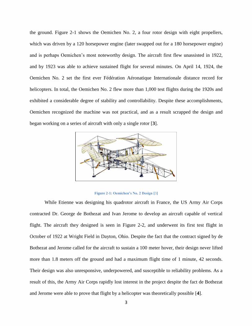
the ground. Figure 2-1 shows the Oemichen No. 2, a four rotor design with eight propellers,
which was driven by a 120 horsepower engine (later swapped out for a 180 horsepower engine)
and is perhaps Oemichen‟s most noteworthy design. The aircraft first flew unassisted in 1922,
and by 1923 was able to achieve sustained flight for several minutes. On April 14, 1924, the
Oemichen No. 2 set the first ever Fédération Aéronatique Internationale distance record for
helicopters. In total, the Oemichen No. 2 flew more than 1,000 test flights during the 1920s and
exhibited a considerable degree of stability and controllability. Despite these accomplishments,
Oemichen recognized the machine was not practical, and as a result scrapped the design and
began working on a series of aircraft with only a single rotor [3].
Figure 2-1: Oemichen’s No. 2 Design [3]
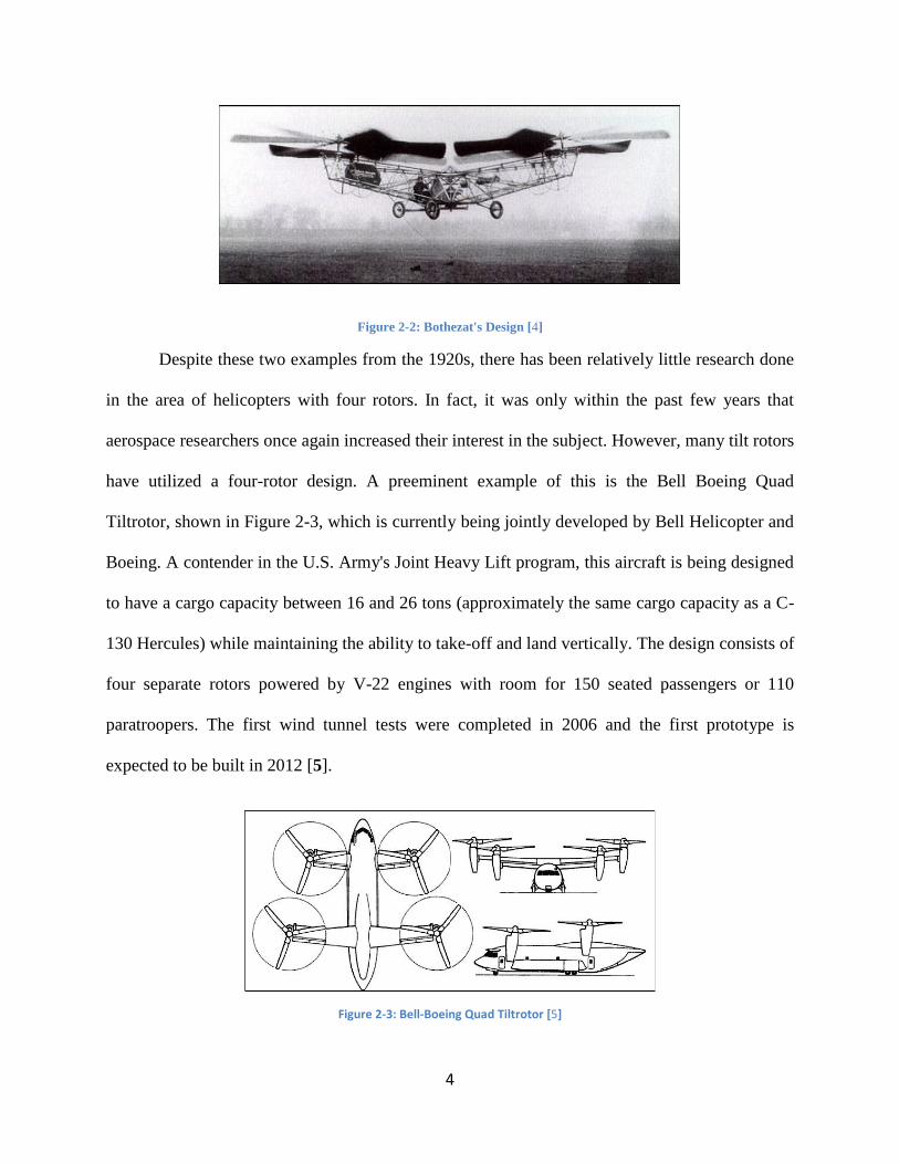
While Etienne was designing his quadrotor aircraft in France, the US Army Air Corps
contracted Dr. George de Bothezat and Ivan Jerome to develop an aircraft capable of vertical
flight. The aircraft they designed is seen in Figure 2-2, and underwent its first test flight in
October of 1922 at Wright Field in Dayton, Ohio. Despite the fact that the contract signed by de
Bothezat and Jerome called for the aircraft to sustain a 100 meter hover, their design never lifted
more than 1.8 meters off the ground and had a maximum flight time of 1 minute, 42 seconds.
Their design was also unresponsive, underpowered, and susceptible to reliability problems. As a
result of this, the Army Air Corps rapidly lost interest in the project despite the fact de Bothezat
and Jerome were able to prove that flight by a helicopter was theoretically possible [4].
4
Figure 2-2: Bothezat's Design [4]
Despite these two examples from the 1920s, there has been relatively little research done
in the area of helicopters with four rotors. In fact, it was only within the past few years that
aerospace researchers once again increased their interest in the subject. However, many tilt rotors
have utilized a four-rotor design. A preeminent example of this is the Bell Boeing Quad
Tiltrotor, shown in Figure 2-3, which is currently being jointly developed by Bell Helicopter and
Boeing. A contender in the U.S. Army's Joint Heavy Lift program, this aircraft is being designed
to have a cargo capacity between 16 and 26 tons (approximately the same cargo capacity as a C-
130 Hercules) while maintaining the ability to take-off and land vertically. The design consists of
four separate rotors powered by V-22 engines with room for 150 seated passengers or 110
paratroopers. The first wind tunnel tests were completed in 2006 and the first prototype is
expected to be built in 2012 [5].
Figure 2-3: Bell-Boeing Quad Tiltrotor [5]
5
3. Goals and Methodology
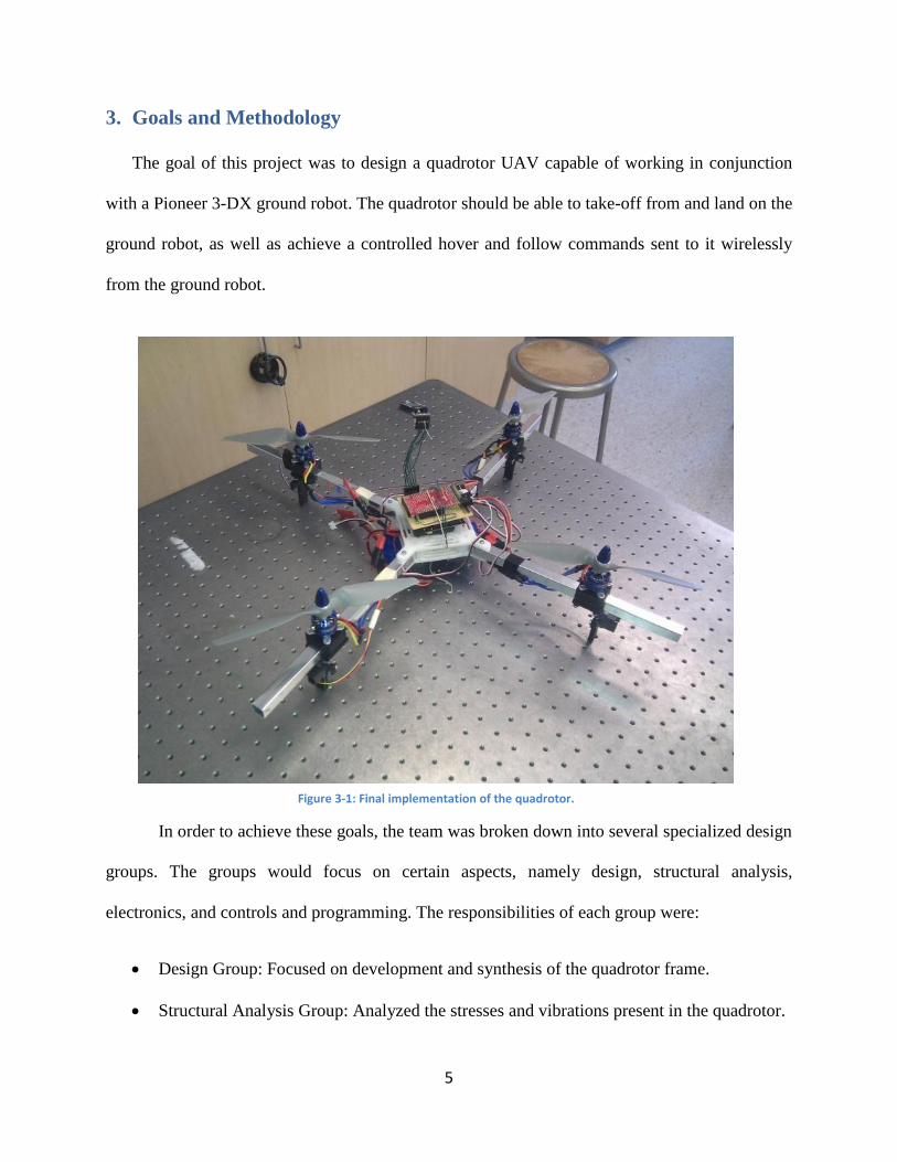
The goal of this project was to design a quadrotor UAV capable of working in conjunction
with a Pioneer 3-DX ground robot. The quadrotor should be able to take-off from and land on the
ground robot, as well as achieve a controlled hover and follow commands sent to it wirelessly
from the ground robot.
In order to achieve these goals, the team was broken down into several specialized design
groups. The groups would focus on certain aspects, namely design, structural analysis,
electronics, and controls and programming. The responsibilities of each group were:
Design Group: Focused on development and synthesis of the quadrotor frame.
Structural Analysis Group: Analyzed the stresses and vibrations present in the quadrotor.
Figure 3-1: Final implementation of the quadrotor.

6
Electronics Group: Determined the appropriate electronics and implemented them.
Controls Group: Researched, derived, and programmed into the quadrotor the equations
governing the motion of the quadrotor as well as the control methods.
Using the combined work of these groups, it is possible to create a completed quadrotor that can
meet the project goals should be functional. The final implementation of the quadrotor is shown
in Figure 3-1.
4. Rotor Dynamics
In order to understand how the quadrotor flies, it is important to understand how a propeller
works. This is because as the thrust-producing component, the propeller is instrumental for
flight.
Propellers work by using Newton‟s Third Law of motion and the principles of lift. The
propeller exerts a force on the air as it passes through, which accelerates the air. Newton‟s Third
Law states that a reaction must take place, which pushes the propeller, and in turn the craft,
forward. Additionally, the blades of the propeller are not flat, but have an airfoil shape to them
in order to more effectively push the air. This works on the same principle as an airplane wing: a
pressure differential between each side of the airfoil produces a force that pushes the propeller
(and therefore the craft) forward. These two effects working together produce the thrust
necessary to make planes and helicopters fly.
4.1 Basic Equations
The thrust a propeller generates can be measured in multiple ways. The most effective
way is to use a test stand to quantitatively measure the thrust, but this can be time consuming and
requires additional physical components (the test stand). An alternative to actually measuring the
7
thrust is to analytically calculate an estimation of the thrust, which is achievable through several
methods. The main approaches can be split into two categories: pressure-based and mass flow-
based.
The pressure based equation multiplies the sweep area of the propeller and the change in
pressure on each side of the propeller:
where (e represents downstream of the propeller, and i upstream). The values
for these static pressures can be calculated with the following equation:
where p0 is static pressure, ρ is air density, and V is air velocity. The thrust can then be
expressed in terms of the differences in velocity when combined with the first equation:
An alternate method of reaching the same equation involves the use of mass flow rates
instead of pressures. The initial equation uses Newton‟s third law and states:
In order to continue, we must find the velocity of the air at the propeller, which is assumed to be
the average of each side of the propeller:

8
From this, it is possible to solve for the mass flow rate; this is then combined with the previous
two equations to get the same equation as when beginning with pressure terms:
However, if velocity terms are not easily measurable, an alternate method needs to be derived in
order to model accurate thrust values.
4.2 Deriving the Propeller Thrust Equation
In order to accurately predict the motion of the quadrotor in simulation, an equation that
relates RPM to thrust must be derived. To do this, an equation based on the principles of
Newton‟s Third Law of Motion is used. The equation is derived as follows:
where ρ = air density (kg/m3), r = propeller radius (inches), and P = propeller pitch (inches).
Converting units from imperial to metric:
( ⁄ )
and
Converting units from imperial to metric:
( ⁄ )
Combining:
( ⁄ )

9
( ⁄ ) ⁄
However, it is important to note that this formula does make certain assumptions:
(airspeed directly above the propeller) is assumed to be zero. Obviously this cannot be
the case or else no air would ever pass through, but while the quadrotor is in a hover, the
air is not actively moving towards the propeller at a significant rate.
Constant hover is assumed. This can be linked to the first assumption, since any high rate
of motion would result in higher . Because the quadrotor will not be moving at high
rates of vertical motion, this is a safe assumption.
The air is assumed to have constant density. This is perhaps the biggest assumption as it
postulates that air is incompressible.
All of these assumptions will be compensated for in the equations below. To help refine
the derived equation, the motors and propellers were tested using a thrust test stand (Figure 9-3),
which gave the RPM/thrust relation. By matching the curve produced through the above
equation with the curve made by the thrust test stand measurements, it was concluded that the
propellers were operating at approximately 34% efficiency. Thus, the final equation becomes:
( ⁄ ) ⁄
Since 9x6 (9 inch diameter, 6 inch pitch) propellers were chosen for this project, and assuming
standard sea-level air density, the equation can be further reduced to its final form:
The above equation, relating RPM to kilograms of thrust, can be used in simulations of the quad
rotor. Even though it is an estimate, it matches the actual measured data closely enough within

10
the predicted RPM range for calibration purposes when a calibration coefficient of .34 is added
to the equation.
4.3 Propeller Wake
An important aspect to consider when analyzing propellers is the downdraft or the wake
downstream of the propeller. Since the quadrotor consists of four propellers, wake interaction
should be considered. The most powerful of these
interactions are the tip vortices, which are swirling patterns
of air that come off the tips of each blade, as seen in
Figure 4-1. Research has shown that these vortices move
downward with hardly any radial movement. Based on the
previous MQP, leaving one inch between the propellers
will be adequate distance to negate any concerns regarding
tip vortices [6].
5. Mechanical Design
The design of the quadrotor was based on several factors: the team‟s knowledge of design,
the previous MQP‟s work, and other quadrotor projects that were discovered while doing the
literature review. The team felt that it was important to incorporate lessons learned from other
groups in order to not repeat errors in past designs. Specifically, the current design is of an
increased size from the previous MQP, which promotes a more rigid structure in conjunction
with allowing for an increased payload, in the form of more advanced electronics and sensors.
The quadrotor frame design goal from 2008-2009 MQP, shown in Figure 5.1, was to reduce
the weight by 10% of the 2007-2008 MQP‟s design, which was constructed from Aluminum
Figure 4-1: Propeller Wake [6]

11
6061. The 2008-2009 MQP used a rapid prototype printer (3D printer) to manufacture the frame
out of ABS plastic, making it susceptible to breaking under high loads or impact. The frame had
a total mass of 39 grams. This included the frame, motor brackets and the cylindrical carbon
fiber arms, as shown in Figure 5-1. The arms on this frame were cylindrical, so the motors
would have to be checked for proper alignment.
Figure 5-1: 08-09 MQP quadrotor
This project‟s quadrotor weights 1 kilogram including the frame, motor brackets, aluminum
arms, motor, IR sensors and wires. With the battery and computer onboard, the quadrotor totals
1.6 kilograms. The arms chosen for this project are square, so as to avoid the motor alignment
issues encountered by the previous MQP. The frame is made from Delrin plastic, which is more
durable than ABS plastic and can withstand impacts but is heavier than ABS. The frame was also
designed with a larger surface area to accommodate additional sensors.
5.1 Design Considerations
The quadrotor‟s structure combines the successful elements of other builds into one: “cross-
bar” arms for motor mounting, a main body on which all the electronic components and sensors
are mounted, and landing gear. The design incorporates these basic components with a two plate
center assembly. The plates act as support for the quadrotor and provide an area for the
electronics to be housed securely. Figure 5-2 shows the design of the two plates and the cross-

12
bar arms. The processor and inertial measurement unit were housed securely on the top plate
vibrationally isolated with foam in order to protect the sensitive electronics. The IR sensors were
placed on the underside of the arms and will attach to the motor brackets that act as the craft‟s
landing gear. The battery was mounted to the bottom plate providing the quad rotor with a
lower, more stable center of gravity which will aid in a more steady flight.
Figure 5-2: Quadrotor CAD model
5.2 Material Selection
The specifications that dictated the choice of material were durability, density (weight), and
price. Table 5-1 illustrates the comparison of different material types and how their
characteristics compare.
Table 5-1: Comparison of Possible Materials for Design
Material Modulus of
Elasticity (GPa)
Tensile Strength
(MPa)
Density (g/cm3)
Nylon 6.6 2.61 82.8 1.14
ABS .001 29.0 1.02
Ultem® 3.45 114 1.28
Delrin® 2.55 52.4 1.42
Carbon Fiber 220 760 1.7
Stainless Steel 404 200 1790 7.80
Aluminum 7075 71 572 2.80
The ideal choice of material would be carbon fiber due to its strength and low weight.
However, due to budgetary concerns, carbon fiber was ruled out and Delrin was chosen as the
13
next best material. Delrin plastic was chosen over any other material due its availability, price
and higher manufacturability than aluminum. A sheet of 64in x 18in Delrin costs about $50.00
and is enough to make 3 frames. Aluminum was used for the arms due to its availability in a
hollow square extrusion.
5.3 Prototype
As the project progressed, the materials evolved along with the design for practical
reasons. The preliminary model was constructed of balsa wood and fiberglass, which was
intended as a proof-of-concept. This provided a useful three-dimensional model for the team to
begin the layout of the electronic components. It was known that the structure, while providing
key insights into the build, was not practical for use as a testing platform, and the model was
replaced in favor of a more rigid body. Due to this, balsa wood and fiberglass was not
considered as an option for a final material.
This led to the construction of the prototype seen in Figure 5-3, which was built with
aluminum cross arms and a Delrin plastic frame. The new frame provided a more rigid body
along with higher yield and tensile strengths, allowing for thorough testing without concern for
damage to key components (motor, electronics, etc.). The motor mounts and battery connector
were 3D printed with ABS plastic.

14
Figure 5-3: Aluminum Quadrotor Prototype on Thrust Test Stand
5.4 Motor Alignment
The motors were each positioned 9.5 in from the center. Making all the motors the same
distance from the center simplifies the controls. If a motor is out of position it induces a moment
that unnecessarily complicates the controls.
5.5 Propeller Selection
The propellers that were used last year provided the necessary pitch and diameter but one
of them had an imperfection: a notch in the trailing edge. The team purchased new propellers
with the same pitch and a smaller diameter as this would produce the necessary thrust from the
motors that were purchased. The smaller diameter was chosen to allow the quadrotor to fit
through a 70cm (27.5 in) wide doorframe. The material is a composite APS propeller that is a
very rigid and durable material able to withstand rugged flight testing.
Propeller Balancing:
Propeller balancing is important to the flight of the quad rotor. Propellers with blade
imperfections are more prone to vibrations at higher RPMs. An extremely precise magnetized
balancer can be used for this application but a simple test with a dowel should suffice especially
15
considering the material and manufacturer of the propellers that were used. The following
procedures show how to balance a propeller:
Position the propeller on a dowel that is horizontally balanced.
Spin the propeller and observe where it stops, repeat several times.
If it is clearly stopping at one spot or near one spot repeatedly, that indicates an
unbalanced weight between the two. The heavier blade will be pointed downwards and
this is the one that should be augmented by either slight sanding or in a more severe case,
shaved down with a razor.
Performing these procedures showed that the propellers were not in need of any further
balancing.
5.6 Vibration Analysis
The study of vibration mechanics is an important aspect of all designs because mechanical
systems have natural modes and may cause control disturbances due to sensor (accelerometer)
measurement error. For the structure, when a specific force is applied to the mechanical system
the natural mode can be excited which can lead to catastrophic failure of the system. This leads
to the importance of studying the resonance frequency of the quadrotor, which is the frequency
that the system will be exited, to ensure that the natural modes will not be disturbed. As for the
electronics, vibrations cause noise in the measurement; this in turn leads to stability problems.
The natural frequency of the spar is calculated analytically and compared to the shedding
frequency of the propeller. It will also be used to determine the physical limits for maneuvering
before it breaks. Assuming that the spar acts like a cantilever with a fixed end and free at the
other, the natural frequency of aluminum spar is estimated with the following equation:
16
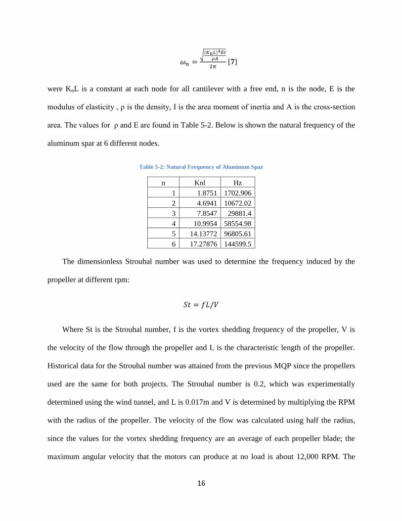
√
[7]
were KnL is a constant at each node for all cantilever with a free end, n is the node, E is the
modulus of elasticity , ρ is the density, I is the area moment of inertia and A is the cross-section
area. The values for ρ and E are found in Table 5-2. Below is shown the natural frequency of the
aluminum spar at 6 different nodes.
Table 5-2: Natural Frequency of Aluminum Spar
n Knl Hz
1 1.8751 1702.906
2 4.6941 10672.02
3 7.8547 29881.4
4 10.9954 58554.98
5 14.13772 96805.61
6 17.27876 144599.5
The dimensionless Strouhal number was used to determine the frequency induced by the
propeller at different rpm:
Where St is the Strouhal number, f is the vortex shedding frequency of the propeller, V is
the velocity of the flow through the propeller and L is the characteristic length of the propeller.
Historical data for the Strouhal number was attained from the previous MQP since the propellers
used are the same for both projects. The Strouhal number is 0.2, which was experimentally
determined using the wind tunnel, and L is 0.017m and V is determined by multiplying the RPM
with the radius of the propeller. The velocity of the flow was calculated using half the radius,
since the values for the vortex shedding frequency are an average of each propeller blade; the
maximum angular velocity that the motors can produce at no load is about 12,000 RPM. The
17
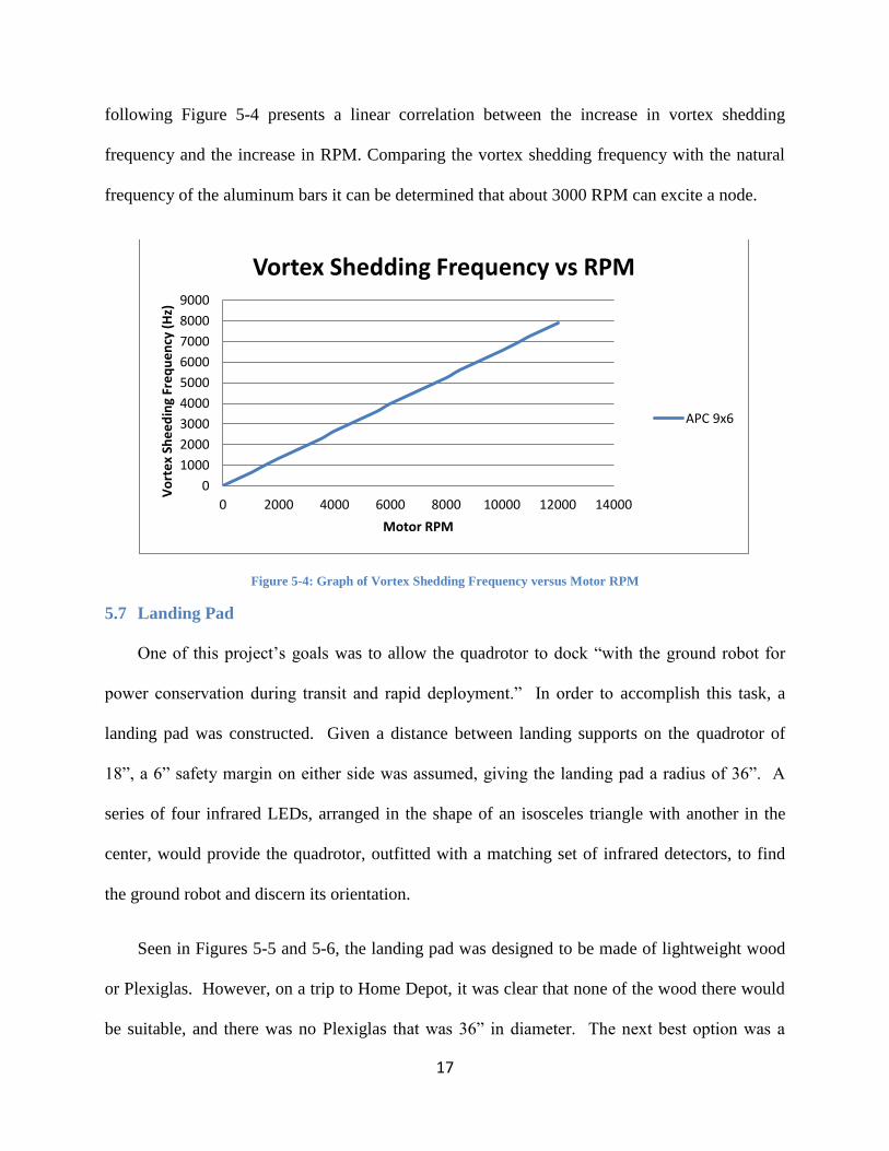
following Figure 5-4 presents a linear correlation between the increase in vortex shedding
frequency and the increase in RPM. Comparing the vortex shedding frequency with the natural
frequency of the aluminum bars it can be determined that about 3000 RPM can excite a node.
Figure 5-4: Graph of Vortex Shedding Frequency versus Motor RPM
5.7 Landing Pad
One of this project‟s goals was to allow the quadrotor to dock “with the ground robot for
power conservation during transit and rapid deployment.” In order to accomplish this task, a
landing pad was constructed. Given a distance between landing supports on the quadrotor of
18”, a 6” safety margin on either side was assumed, giving the landing pad a radius of 36”. A
series of four infrared LEDs, arranged in the shape of an isosceles triangle with another in the
center, would provide the quadrotor, outfitted with a matching set of infrared detectors, to find
the ground robot and discern its orientation.
Seen in Figures 5-5 and 5-6, the landing pad was designed to be made of lightweight wood
or Plexiglas. However, on a trip to Home Depot, it was clear that none of the wood there would
be suitable, and there was no Plexiglas that was 36” in diameter. The next best option was a
0
1000
2000
3000
4000
5000
6000
7000
8000
9000
0 2000 4000 6000 8000 10000 12000 14000
Vo
rte
x Sh
ee
din
g Fr
eq
ue
ncy
(H
z)
Motor RPM
Vortex Shedding Frequency vs RPM
APC 9x6

18
36”x30” Plexiglas rectangle, which was chosen as the material for our landing pad. It was then
painted flat black so as to minimize any environmental reflections that could interfere with the
infrared detectors. It was then attached to the ground robot.
Figure 5-5: Side View of the Landing Pad
Figure 5-6: Aerial View of the Landing Pad
6. Quadrotor Control
Control theory is a branch of engineering and mathematics that deals with the behavior of
dynamic systems. It utilizes controllers to manipulate the inputs of a system to achieve the
desired effect on the output of the system. The cruise control feature on many cars is a great

19
example of a controller. It measures the output from the car (the car‟s speed) and manipulates the
car‟s input (the throttle on the engine) to ensure the car remains around a desired speed.
Although the history of control systems dates back to antiquity, it wasn‟t until relatively recently
(1867) that a more formal analysis of the field of control theory began.
Perhaps the most common and well-known controller used in control theory is the PID
Controller. PID is short for proportional-integral-differential, which refers to the three terms that
operate on the error signal to produce a control signal. The general form for a PID controller is
∫
This MQP‟s quadrotor uses a variation of the PID controller, the PD controller. In this form, only
a proportional and differential term are calculated, no integral term is used.
6.1 Dynamics of Motion
Before it is possible to control a quadrotor, it is first necessary to understand how the
quadrotor behaves by deriving the equations of motion that govern its flight. This can be done
through the use of the Lagrangian equations of motion [1]. The position and orientation of a
quadrotor can be given at any time using the coordinates x, y, z, φ, θ, and ψ. The x, y, and z
variables represent the position of the quadrotor with respect to an inertial frame, while the φ, θ,
and ψ variables are the three Euler angles (roll, pitch, and yaw) and represent the orientation of
the quadrotor. These angles can be seen in Figure 1-1. These variables can be naturally split into
two categories of coordinates: the translational coordinates ξ = (x, y, z) and the rotational
coordinates η = (φ, θ, ψ).
Using these variables, it is possible to calculate both the translational and the rotational
kinetic energies of the quadrotor. The translational kinetic energy of the quadrotor is:
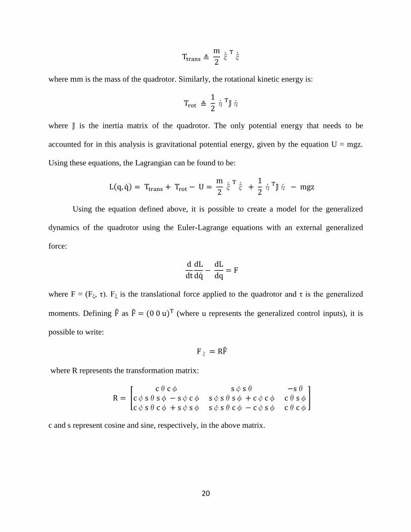
20
where m is the mass of the quadrotor. Similarly, the rotational kinetic energy is:
where is the inertia matrix of the quadrotor. The only potential energy that needs to be
accounted for in this analysis is gravitational potential energy, given by the equation U = mgz.
Using these equations, the Lagrangian can be found to be:
Using the equation defined above, it is possible to create a model for the generalized
dynamics of the quadrotor using the Euler-Lagrange equations with an external generalized
force:
where F = (Fξ, τ). Fξ is the translational force applied to the quadrotor and τ is the generalized
moments. Defining as (where u represents the generalized control inputs), it is
possible to write:
where R represents the transformation matrix:
[
]
c and s represent cosine and sine, respectively, in the above matrix.
21
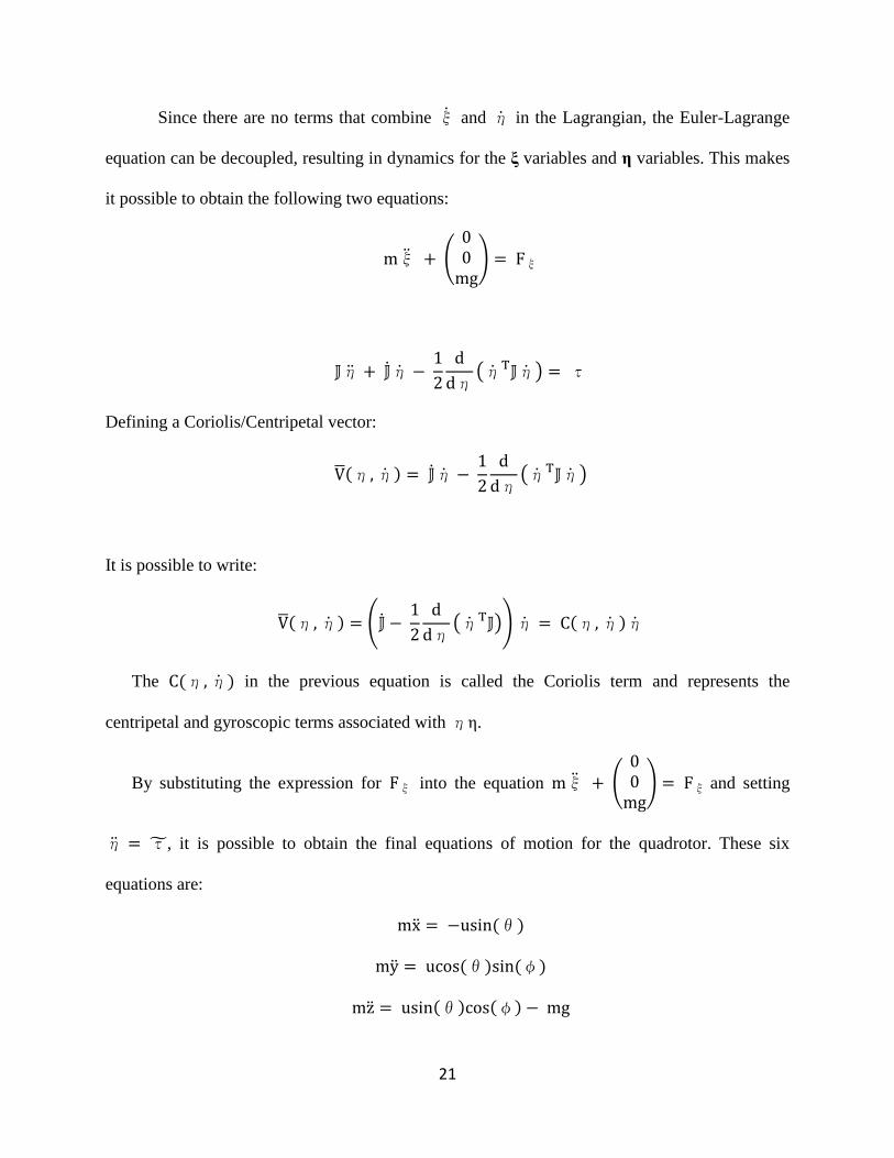
Since there are no terms that combine and in the Lagrangian, the Euler-Lagrange
equation can be decoupled, resulting in dynamics for the ξ variables and η variables. This makes
it possible to obtain the following two equations:
(
)
( )
Defining a Coriolis/Centripetal vector:
( )
It is possible to write:
(
( ))
The in the previous equation is called the Coriolis term and represents the
centripetal and gyroscopic terms associated with η.
By substituting the expression for into the equation (
) and setting
, it is possible to obtain the final equations of motion for the quadrotor. These six
equations are:
22
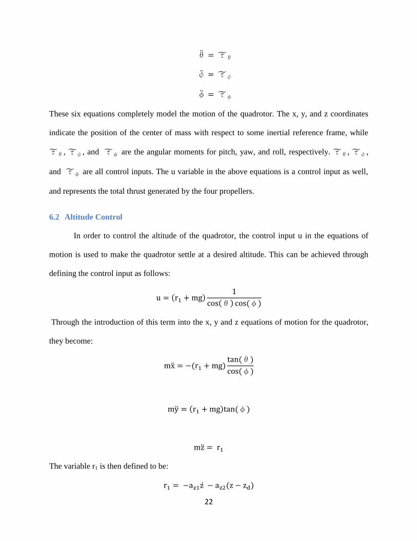
These six equations completely model the motion of the quadrotor. The x, y, and z coordinates
indicate the position of the center of mass with respect to some inertial reference frame, while
, , and are the angular moments for pitch, yaw, and roll, respectively. , ,
and are all control inputs. The u variable in the above equations is a control input as well,
and represents the total thrust generated by the four propellers.
6.2 Altitude Control
In order to control the altitude of the quadrotor, the control input u in the equations of
motion is used to make the quadrotor settle at a desired altitude. This can be achieved through
defining the control input as follows:
Through the introduction of this term into the x, y and z equations of motion for the quadrotor,
they become:
The variable r1 is then defined to be:

23
The variable zd is the desired altitude of the quadrotor and az1 and az2 are positive constants.
Plugging this into the previous equation for , the following equation is derived:
This equation is of the form:
where:
√
From these equations and known data, it is possible to compute the control parameters az1 and az2
to ensure the system has a stable, well-damped response in the z-direction.
6.3 Yaw Control
To control the yaw angle of the quadrotor, the input is used to make the quadrotor
settle at a desired angle. The yaw control follows a similar derivation to that used for the altitude
control, with the only difference being the lack of a mass term. There is no mass term in the
derivation because there is no mass term in the equation of motion for . The equation
simplifies to:
Much like with altitude control, the parameters aψ1 and aψ2 must be chosen to ensure a stable,
well-damped response in the yaw axis. As time increases, the actual yaw angle will approach and
eventually settle at the desired yaw angle.

24
6.4 Pitch and Roll Control
To ensure that the quadrotor doesn‟t exceed certain critical angles that would cause it to
flip and become unstable, it is necessary to place limits on the torque experienced by the
quadrotor. This ensures that angular acceleration in the pitch and roll direction remains relatively
low. The use of saturation functions within the equations for pitch and roll control limits motor
speed, tilt angle, and angular acceleration. The following nonlinear controllers are responsible
for controlling the pitch and roll angle of the quadrotor [1]:
( ( (
(
))))
(
( (
(
)))
)
These control equations are general equations and will control the pitch and roll angles of the
quadrotor for basic maneuvers. Since the quadrotor can be assumed relatively stable at hover
with small pitch and roll angles and slow movement speed, the control equations governing pitch
and roll can be reduced to the following form [6]:
Like before, the parameters aφ1, aφ2, aθ1, and aθ2 must be chosen to ensure the system remains
stable and returns to the desired pitch and roll angles of 0 after a perturbation.

25
Figure 6-2: Simulation of 1 m hover maneuver Figure 6-1: Z-Velocity of quadrotor with 1 m hover
maneuver
6.5 MATLAB Simulation
A series of MATLAB simulations were run to evaluate the theoretical performance of the
control theory governing the flight of the quadrotor. The two motions simulated were an ascent
Figure 6-3: Simulation of Psi maneuver to 45 degrees Figure 6-4: Yaw Velocity with s maneuver to a yaw of 45
degrees
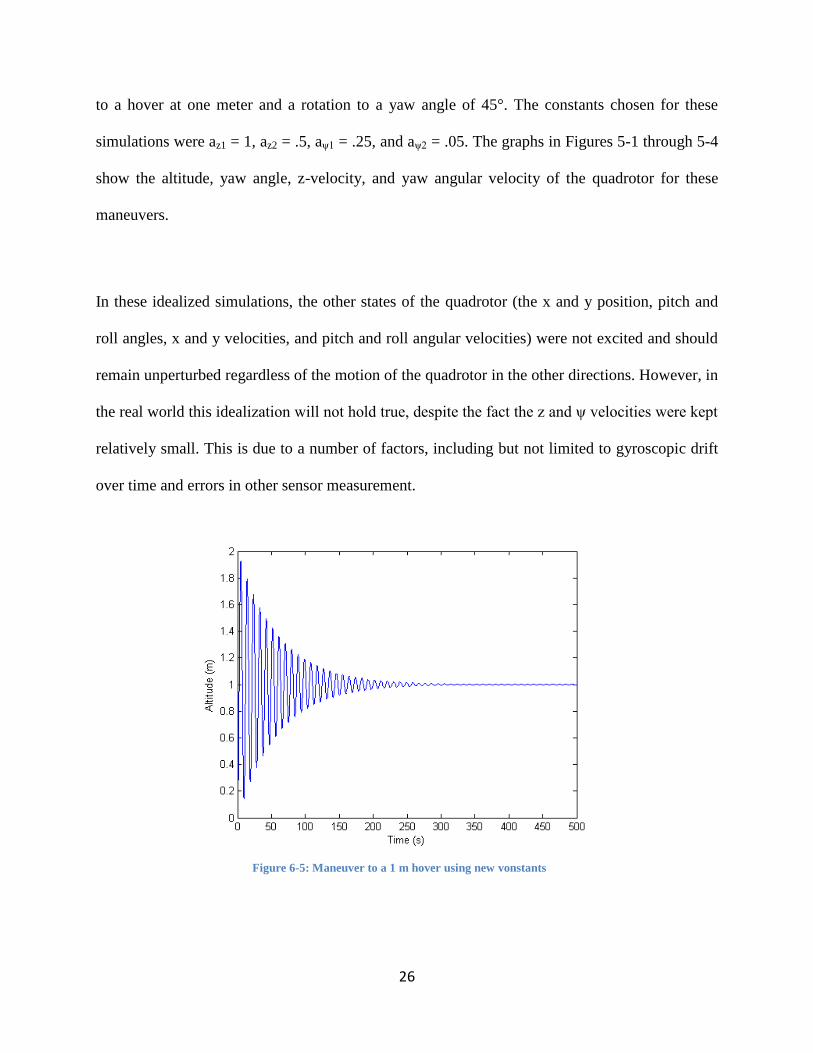
26
to a hover at one meter and a rotation to a yaw angle of 45°. The constants chosen for these
simulations were az1 = 1, az2 = .5, aψ1 = .25, and aψ2 = .05. The graphs in Figures 5-1 through 5-4
show the altitude, yaw angle, z-velocity, and yaw angular velocity of the quadrotor for these
maneuvers.
In these idealized simulations, the other states of the quadrotor (the x and y position, pitch and
roll angles, x and y velocities, and pitch and roll angular velocities) were not excited and should
remain unperturbed regardless of the motion of the quadrotor in the other directions. However, in
the real world this idealization will not hold true, despite the fact the z and ψ velocities were kept
relatively small. This is due to a number of factors, including but not limited to gyroscopic drift
over time and errors in other sensor measurement.
Figure 6-5: Maneuver to a 1 m hover using new vonstants

27
By varying the constants in the control equations, it is possible to alter the time it takes
the quadrotor to reach the desired state. This also has an impact on the acceleration and velocity
of the quadrotor as it performs its maneuvers. This can lead to undesirable characteristics in the
motion of the quadrotor, such as a large settling time or rapid changes in the acceleration and
velocity. Figure 6-5 shows how the motion of the quadrotor is affected by changing the control
constants az1 and az2 to .05 and .67, respectively. Note how the altitude of the quadrotor varies
from just under .2 m to almost 2 m, and how it takes the quadrotor about 300s to converge to the
desired altitude.
6.6 Speed and Motor Control
Knowing the speed of the motors allows the thrust to be controlled, which in turns allows
for stable maneuvers. One method of acquiring the thrust of the motors would be using a lookup
table to see what the thrust is at a given PWM signal. This method, however, can prove to be
inaccurate, as the thrust values at a given RPM are obtained through testing on a thrust stand.
Conditions on the thrust stand will likely not be the same as the conditions on a flying quadrotor,
meaning that the thrust values obtained in testing may not hold true for some instances of
operation. A more accurate estimation of the thrust from each motor can be obtained by using
active sensors on the quadrotor. Hall Effect switches for instance, can be used to get the RPMs of
each motor, as discussed in the Electronics section. With a known RPM the thrust can be
approximated using the equation discussed in the Rotor Dynamics section. An estimation for
thrust allows the quadrotor to converge towards any required thrust generated by the control
equations presented earlier in this section. This convergence is gained through the use of a PID
loop that makes adjustments based on the error between the desired and estimated thrust. While

28
time and material limitations prevented the actual PID gains from being calculated, these values
could be obtained through experimentation with the quadrotor.
7. Electrical System
When designing the electrical system for the quadrotor there were many factors to
consider. While these factors usually varied depending on the component being considered (i.e.
processor, motor, etc.), some attributes were desirable regardless of the component. The main
characteristics that drove the selection of electronics were:
Low Power Consumption – Components that use less power will allow the quad rotor to
achieve longer flight times, which is desirable in just about any task that it could be
assigned.
Low Weight – Being lighter will allow the motors to use less energy to keep the quad
rotor in the air, allowing for extended flight times.
Small Footprint – Taking up less space means the frame can be smaller and still
accommodate all the required parts, reducing the weight and size of the entire quadrotor.
Low Cost – The budget for this project is not exceedingly large, and while it should be
sufficient, the components should all preferably be inexpensive so that repairs and
additional units are as low-cost as possible.
A table of all the electronics that were selected can be found in Appendix A.
7.1 Processing
The processor is arguably the most important part of any electronic system, as it dictates
the limitations of the system concerning the speed everything operates at and what other
components can be used. The important attributes when choosing the processor were:
29
Processing Speed – How many instructions can be executed per second. Higher speeds
are often preferred, but faster processors also require additional cooling and power in
addition to being more expensive.
Digital Ports – Allow digital information (high state or low state) to be read in, such as
the state of buttons or infrared obstacle switches. These ports can also output data, such
as serial data or pulse width modulation (PWM) signals.
Analog Ports – Allow analog signals (any state at or between high and low) to be read in,
such as information from rangefinders or gyroscopes. Along with the number of ports,
the analog-to digital converter (ADC) should have a high resolution in order to more
accurately read analog signals.
Communication Interfaces – The processor must be able to communicate with other
systems and processors in order to coordinate actions, delegate tasks and receive
information. This can be accomplished through several different established methods, but
for this project the main concern was the ability to communicate via a Universal
Asynchronous Receiver Transmitter (UART) protocol.
Keeping these aspects in mind, the following components for the quadrotor were chosen:
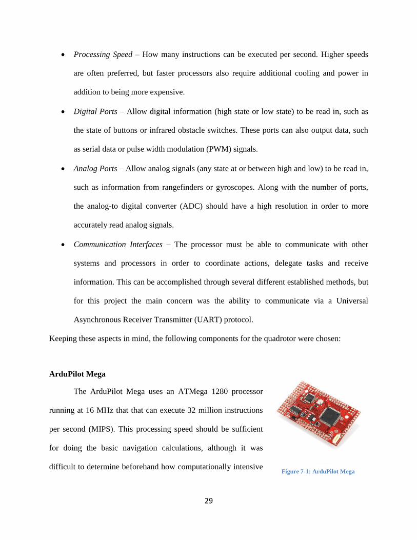
ArduPilot Mega
The ArduPilot Mega uses an ATMega 1280 processor
running at 16 MHz that that can execute 32 million instructions
per second (MIPS). This processing speed should be sufficient
for doing the basic navigation calculations, although it was
difficult to determine beforehand how computationally intensive Figure 7-1: ArduPilot Mega
30
the program would be, and any calculations that slow the processor down too much can be
handed off to the ground robot. There are also 16 analog input pins which is just around the 15
that we require for our components (6 on the IMU and 9 on other sensors) and 8 PWM outputs, 4
of which are needed to control the motors. The ADC of the analog pins is 10 bits, giving a
resolution of 4.8828 mV/bit on the 5V at which the system runs. Additionally, there are four
dedicated serial ports for two-way communication via UART or any similar protocol, which is
above the two that the specifications require. The required memory of this project was difficult to
calculate beforehand, but this processor comes with 124 KB of memory for programs, which was
estimated to be more than sufficient for the program. The entire board takes up approximately
0.5 cubic inches, weighs 35 grams, and only consumes about 9 mW of power while running.
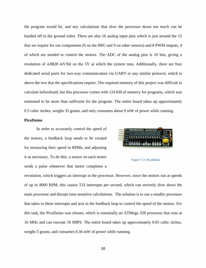
PicoDuino
In order to accurately control the speed of
the motors, a feedback loop needs to be created
for measuring their speed in RPMs, and adjusting
it as necessary. To do this, a sensor on each motor
sends a pulse whenever that motor completes a
revolution, which triggers an interrupt in the processor. However, since the motors run at speeds
of up to 8000 RPM, this causes 533 interrupts per second, which can severely slow down the
main processor and disrupt time-sensitive calculations. The solution is to use a smaller processor
that takes in these interrupts and acts in the feedback loop to control the speed of the motors. For
this task, the PicoDuino was chosen, which is essentially an ATMega 328 processor that runs at
16 MHz and can execute 16 MIPS. The entire board takes up approximately 0.05 cubic inches,
weighs 5 grams, and consumes 0.36 mW of power while running.
Figure 7-2: PicoDuino
31
7.2 Motor Control
Having the correct motors is critical to any quadrotor, as
they must be powerful enough to lift the frame and other
components while still having enough additional power to deliver
sufficient mobility to the system. Brushless DC motors were
chosen because of their high efficiency, small weight, fast
speeds, and simple implementation. The main attributes focused
on when evaluating motors were their „kv‟ rating: how many
RPMs per volt they produce, and their power consumption in amperes. These values were
studied because they gave an idea of how a given motor will operate, determining how fast the
propellers would likely spin as well as how much power the motor would be expected to draw.
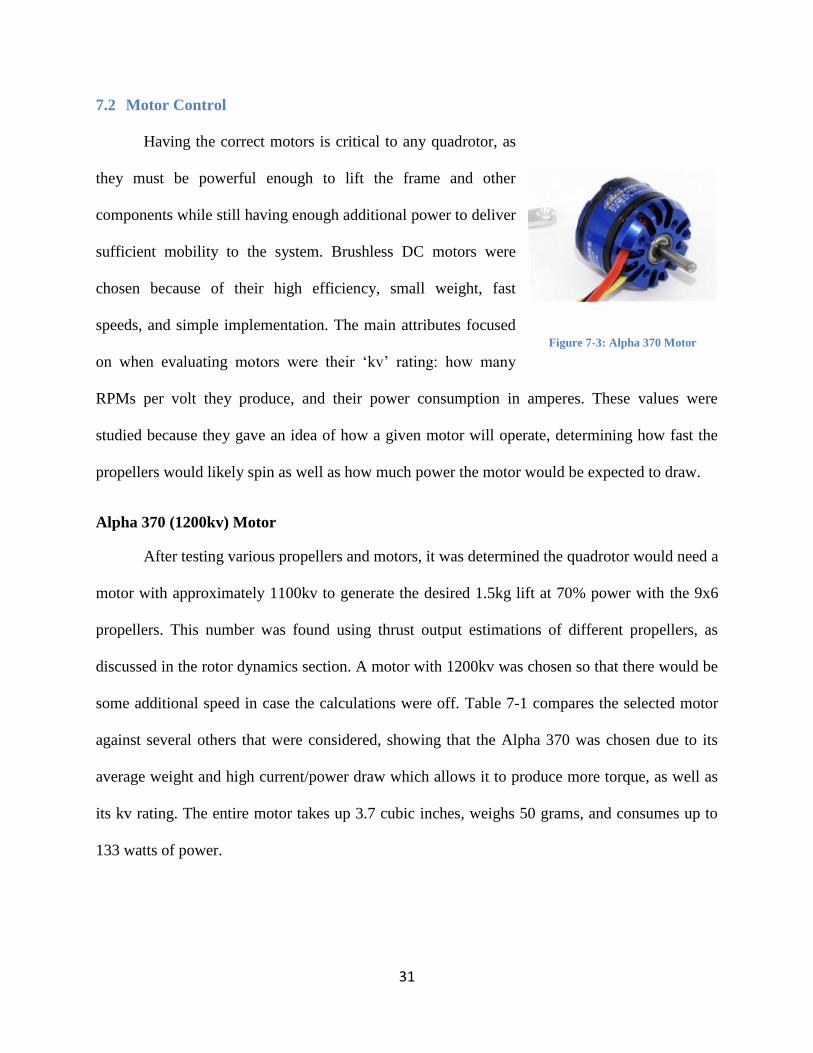
Alpha 370 (1200kv) Motor
After testing various propellers and motors, it was determined the quadrotor would need a
motor with approximately 1100kv to generate the desired 1.5kg lift at 70% power with the 9x6
propellers. This number was found using thrust output estimations of different propellers, as
discussed in the rotor dynamics section. A motor with 1200kv was chosen so that there would be
some additional speed in case the calculations were off. Table 7-1 compares the selected motor
against several others that were considered, showing that the Alpha 370 was chosen due to its
average weight and high current/power draw which allows it to produce more torque, as well as
its kv rating. The entire motor takes up 3.7 cubic inches, weighs 50 grams, and consumes up to
133 watts of power.
Figure 7-3: Alpha 370 Motor
32
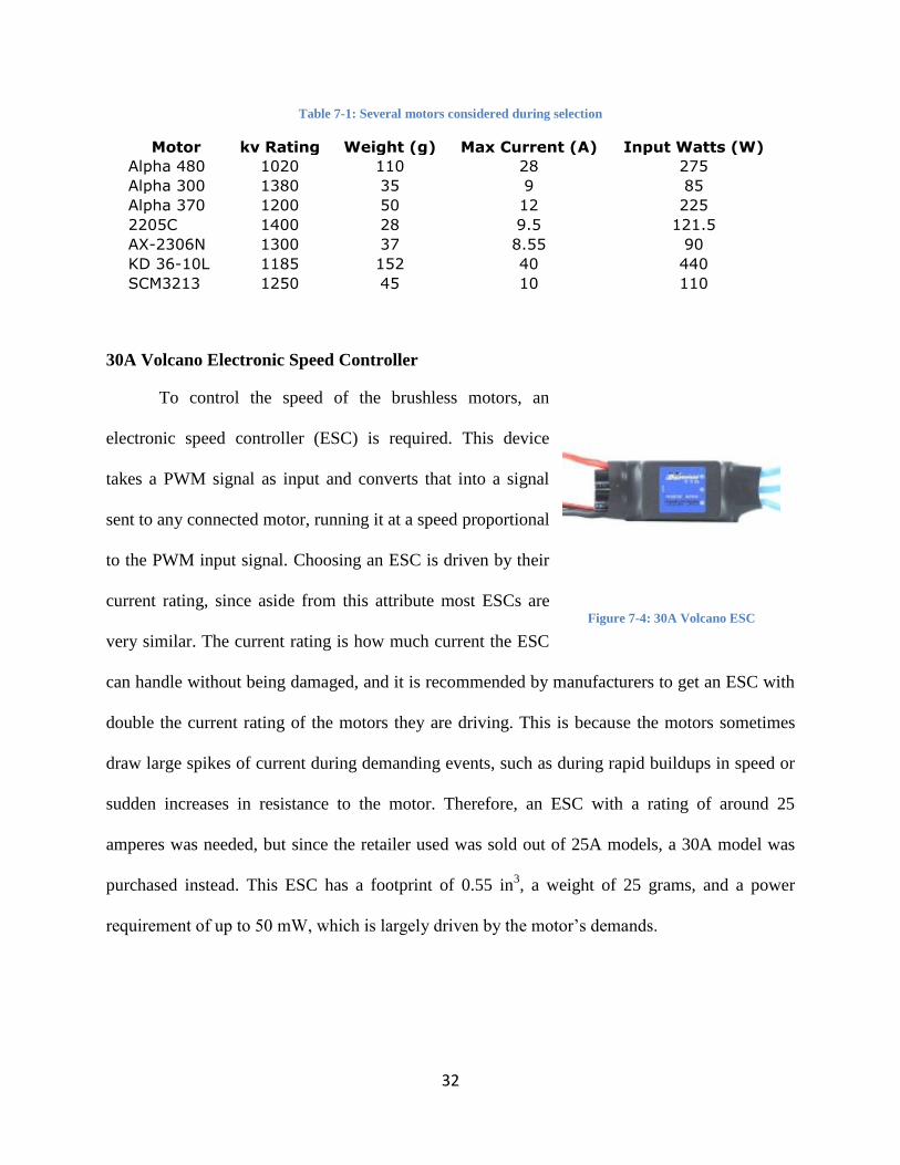
Table 7-1: Several motors considered during selection
Motor kv Rating Weight (g) Max Current (A) Input Watts (W)
Alpha 480 1020 110 28 275
Alpha 300 1380 35 9 85
Alpha 370 1200 50 12 225
2205C 1400 28 9.5 121.5
AX-2306N 1300 37 8.55 90
KD 36-10L 1185 152 40 440
SCM3213 1250 45 10 110
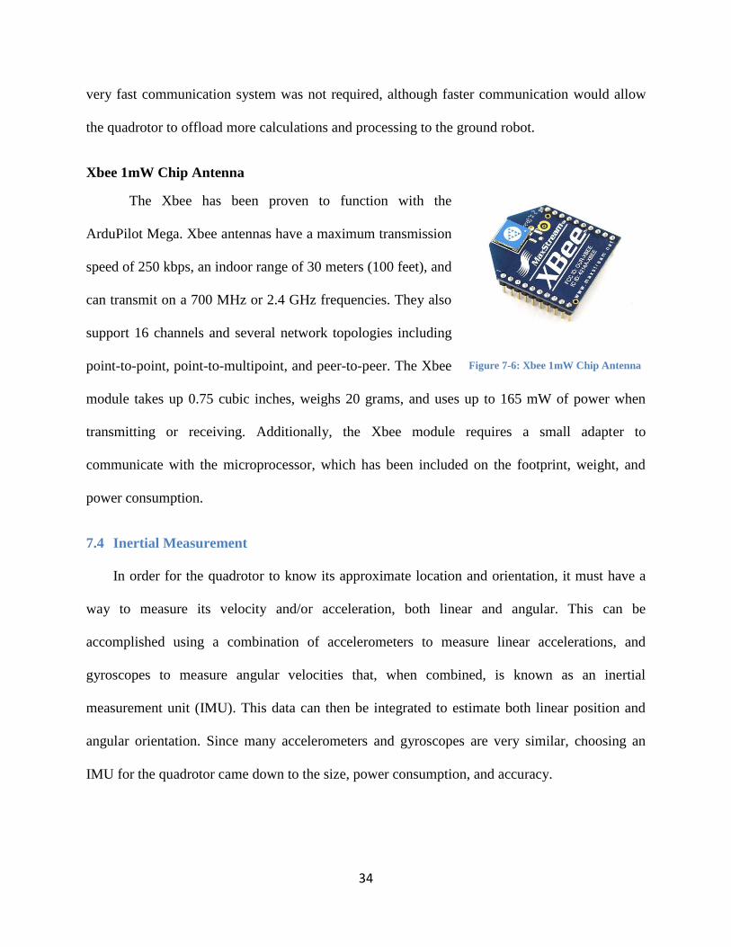
30A Volcano Electronic Speed Controller
To control the speed of the brushless motors, an
electronic speed controller (ESC) is required. This device
takes a PWM signal as input and converts that into a signal
sent to any connected motor, running it at a speed proportional
to the PWM input signal. Choosing an ESC is driven by their
current rating, since aside from this attribute most ESCs are
very similar. The current rating is how much current the ESC
can handle without being damaged, and it is recommended by manufacturers to get an ESC with
double the current rating of the motors they are driving. This is because the motors sometimes
draw large spikes of current during demanding events, such as during rapid buildups in speed or
sudden increases in resistance to the motor. Therefore, an ESC with a rating of around 25
amperes was needed, but since the retailer used was sold out of 25A models, a 30A model was
purchased instead. This ESC has a footprint of 0.55 in3, a weight of 25 grams, and a power
requirement of up to 50 mW, which is largely driven by the motor‟s demands.
Figure 7-4: 30A Volcano ESC

33
ATS177 Hall Effect Switch
In order to utilize the desired control methods, the RPM of each motor at all times during
flight must be determined. The PWM signal is not a reliable way to measure speed because that
would require a lookup table of the RPMs of the motor at every given PWM signal. This would
still not be accurate all the time because of the way ESCs often increase and decrease the motor
speed to the desired value in a nonlinear fashion. In addition to
this, there is additional uncertainty added from resistance to the
propellers and other unforeseen circumstances that would be
undetectable if only the PWM signal sent to the motors was acted
on. Therefore, Hall Effect switches were used to sense when each
motor made a complete revolution. The Hall Effect switch outputs
a high value whenever it senses a strong enough electromagnetic field, as generated by a magnet
on the outside of the brushless motors. This high value triggers an interrupt on one of the
processors, and if it is known that „x‟ interrupts equals one revolution, the processor will be able
to determine how many RPM each motor is operating at. The Hall Effect Switches are small, and
only take up 0.002 cubic inches, weigh 1 gram, and use 25mW of power.
7.3 Telemetry
Since the quadrotor uses a ground robot as its base station, both robots need a way to
communicate with one another to coordinate their actions and give/receive commands. The
assumed distance between the quadrotor and ground robot was approximately 50 feet due to the
nature of the proposed operations the quadrotor was conducting. However, signal occlusion due
to obstacles between the robots also needed to be accounted for when choosing the
communication method. The amount of data beign transmitted was not be very large; therefore a
Figure 7-5: ATS177 Hall Effect
Switch
34
very fast communication system was not required, although faster communication would allow
the quadrotor to offload more calculations and processing to the ground robot.
Xbee 1mW Chip Antenna
The Xbee has been proven to function with the
ArduPilot Mega. Xbee antennas have a maximum transmission
speed of 250 kbps, an indoor range of 30 meters (100 feet), and
can transmit on a 700 MHz or 2.4 GHz frequencies. They also
support 16 channels and several network topologies including
point-to-point, point-to-multipoint, and peer-to-peer. The Xbee
module takes up 0.75 cubic inches, weighs 20 grams, and uses up to 165 mW of power when
transmitting or receiving. Additionally, the Xbee module requires a small adapter to
communicate with the microprocessor, which has been included on the footprint, weight, and
power consumption.
7.4 Inertial Measurement
In order for the quadrotor to know its approximate location and orientation, it must have a
way to measure its velocity and/or acceleration, both linear and angular. This can be
accomplished using a combination of accelerometers to measure linear accelerations, and
gyroscopes to measure angular velocities that, when combined, is known as an inertial
measurement unit (IMU). This data can then be integrated to estimate both linear position and
angular orientation. Since many accelerometers and gyroscopes are very similar, choosing an
IMU for the quadrotor came down to the size, power consumption, and accuracy.
Figure 7-6: Xbee 1mW Chip Antenna

35
Razor 6DOF Inertial Measurement Unit
The Razor 6DOF IMU was chosen chiefly because of
its small size and built-in hardware filtering of the
accelerometer and gyroscope signals. In addition to this, the
gyroscopes have a range of 300°/s with a sensitivity of 3.33
mV/°/s, and the accelerometers have a ±3g range and a
sensitivity of 300 mV/g. This means that the IMU is sensitive enough for the needs of this
project, and has a range that while larger than basic requirements, could be useful during
development of aggressive maneuvers. This IMU takes up 0.23 cubic inches, weighs 9 grams,
and consumes 41 mA of power.
7.5 Active Sensing
Active sensors are needed by the quadrotor to learn about its environment. Specifically, the
quadrotor needs to know if it is in danger of colliding with any nearby objects or the ground.
This can be accomplished with rangefinder sensors that measure the distance to any object they
are pointing at, allowing the processor to calculate trajectories to avoid collisions. When
choosing sensors, the main concerns were mainly maximum measurable distance, the time it
takes to get an accurate measurement after moving, and the sensitivity to peripheral objects.
Figure 7-7: Razor 6DOF IMU
36
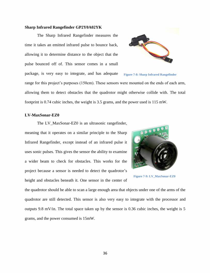
Sharp Infrared Rangefinder GP2Y0A02YK
The Sharp Infrared Rangefinder measures the
time it takes an emitted infrared pulse to bounce back,
allowing it to determine distance to the object that the
pulse bounced off of. This sensor comes in a small
package, is very easy to integrate, and has adequate
range for this project‟s purposes (150cm). These sensors were mounted on the ends of each arm,
allowing them to detect obstacles that the quadrotor might otherwise collide with. The total
footprint is 0.74 cubic inches, the weight is 3.5 grams, and the power used is 115 mW.
LV-MaxSonar-EZ0
The LV_MaxSonar-EZ0 is an ultrasonic rangefinder,
meaning that it operates on a similar principle to the Sharp
Infrared Rangefinder, except instead of an infrared pulse it
uses sonic pulses. This gives the sensor the ability to examine
a wider beam to check for obstacles. This works for the
project because a sensor is needed to detect the quadrotor‟s
height and obstacles beneath it. One sensor in the center of
the quadrotor should be able to scan a large enough area that objects under one of the arms of the
quadrotor are still detected. This sensor is also very easy to integrate with the processor and
outputs 9.8 mV/in. The total space taken up by the sensor is 0.36 cubic inches, the weight is 5
grams, and the power consumed is 15mW.
Figure 7-8: Sharp Infrared Rangefinder
Figure 7-9: LV_MaxSonar-EZ0
37
7.6 Battery
The battery is critical to the operation of the quadrotor, as it not only determines how
long it can stay operational, but also how powerful the motors can be and how much energy is
left for other parts of the system. A lithium polymer battery was chosen due to their high energy-
to-weight ratio. While they are somewhat expensive, they were well within the project‟s budget.
Furthermore, a 3-cell battery was purchased, providing 11.1V, which is standard voltage to
control most hobby motors and the ESCs that the project uses. The two main attributes that need
to be considered when choosing a battery are the milliamp-hours it can supply, and its „C‟ rating.
The C rating determines how many amperes can be drawn from the battery at any given time, for
example, a 1000mAh 25C battery would be able to draw at most 25000 mA at any given time.
There is also a burst C rating, which determines how much can be drawn from the battery in
bursts (10 second spans of time). Although the main concern was with the constant C rating, the
„burst‟ rating is important for quick maneuvering and speed changes.
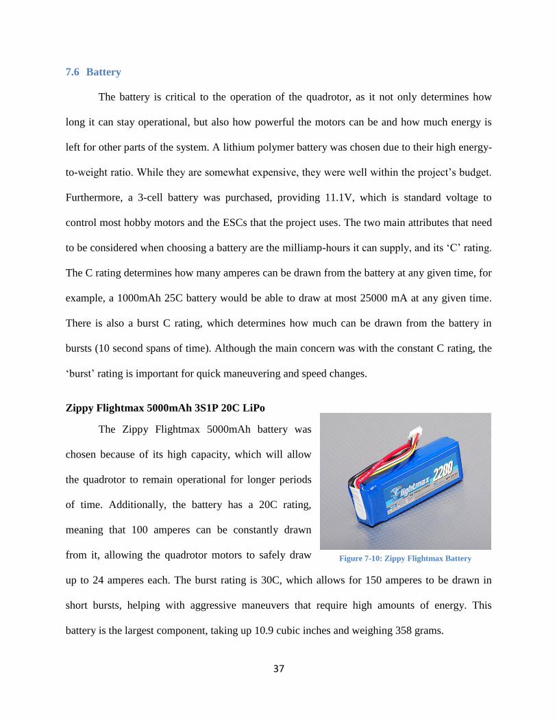
Zippy Flightmax 5000mAh 3S1P 20C LiPo
The Zippy Flightmax 5000mAh battery was
chosen because of its high capacity, which will allow
the quadrotor to remain operational for longer periods
of time. Additionally, the battery has a 20C rating,
meaning that 100 amperes can be constantly drawn
from it, allowing the quadrotor motors to safely draw
up to 24 amperes each. The burst rating is 30C, which allows for 150 amperes to be drawn in
short bursts, helping with aggressive maneuvers that require high amounts of energy. This
battery is the largest component, taking up 10.9 cubic inches and weighing 358 grams.
Figure 7-10: Zippy Flightmax Battery
38
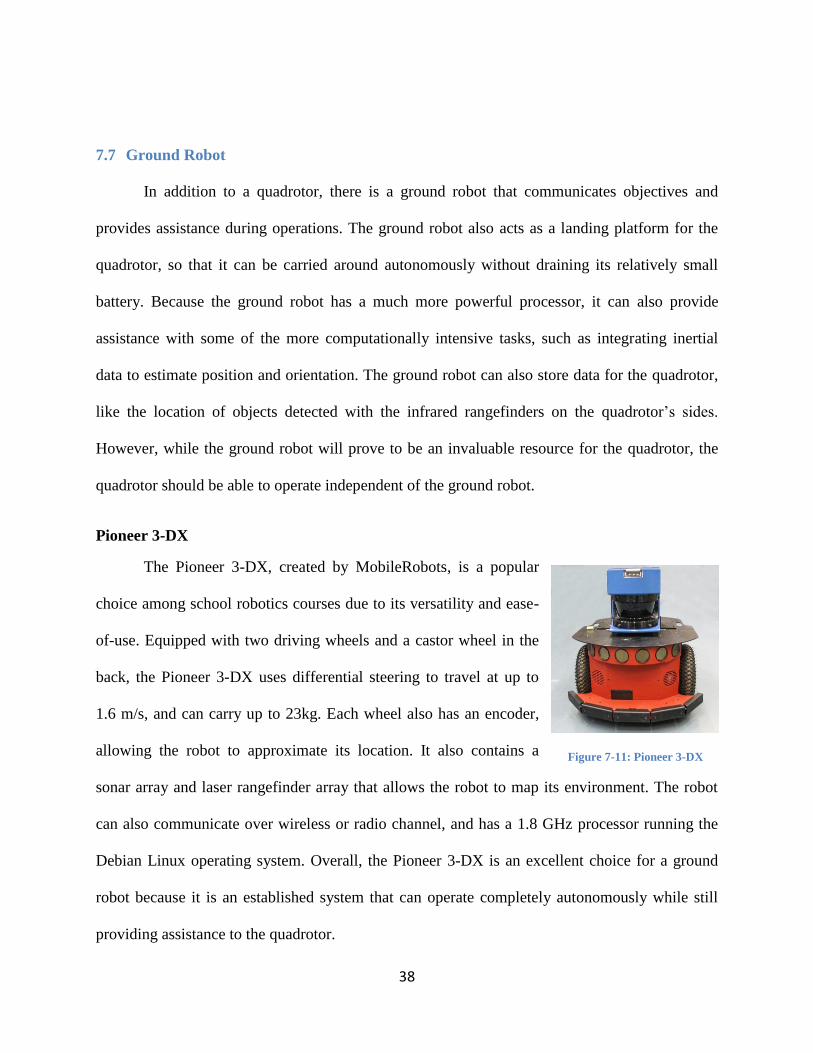
7.7 Ground Robot
In addition to a quadrotor, there is a ground robot that communicates objectives and
provides assistance during operations. The ground robot also acts as a landing platform for the
quadrotor, so that it can be carried around autonomously without draining its relatively small
battery. Because the ground robot has a much more powerful processor, it can also provide
assistance with some of the more computationally intensive tasks, such as integrating inertial
data to estimate position and orientation. The ground robot can also store data for the quadrotor,
like the location of objects detected with the infrared rangefinders on the quadrotor‟s sides.
However, while the ground robot will prove to be an invaluable resource for the quadrotor, the
quadrotor should be able to operate independent of the ground robot.
Pioneer 3-DX
The Pioneer 3-DX, created by MobileRobots, is a popular
choice among school robotics courses due to its versatility and ease-
of-use. Equipped with two driving wheels and a castor wheel in the
back, the Pioneer 3-DX uses differential steering to travel at up to
1.6 m/s, and can carry up to 23kg. Each wheel also has an encoder,
allowing the robot to approximate its location. It also contains a
sonar array and laser rangefinder array that allows the robot to map its environment. The robot
can also communicate over wireless or radio channel, and has a 1.8 GHz processor running the
Debian Linux operating system. Overall, the Pioneer 3-DX is an excellent choice for a ground
robot because it is an established system that can operate completely autonomously while still
providing assistance to the quadrotor.
Figure 7-11: Pioneer 3-DX

39
8. Programming
In order for the quadrotor and ground robot to work properly as a system, the programs
running on both robots must be working in unison to maximize the success rate of all the
quadrotor‟s orders. This means having the ground robot clearly communicate objectives as well
as having the quadrotor remember and attempt to complete the objectives to the best of its
ability, and is seen at the Objective Level in Figure 8-1. One step below the objective level is the
Planning Level, which, for the quadrotor means that a path must be calculated to reach the goal
position, or recalculated if an object gets in the way. For the ground robot, the planning level is
handled manually by a user piloting the robot or a program running on the robot. Below this is
the Estimation Level, which keeps track of objects and the quadrotor‟s position in space. The
lowest level is the Hardware Level, which maintains the proper motor speed to get the desired
amount of thrust, and gathers readings from the various sensors onboard the quadrotor. With
these areas defined, a clearer picture of what code would be needed on both robots for the
objectives to be completed successfully was compiled.

40
Figure 8-1: Overall levels of code being used by the quadrotor and ground robot.
8.1 Quadrotor Programming
The classes involved in the quad rotor were developed based on the levels from Figure 8-
1. The Unified Markup Language (UML) diagram of the classes involved is shown in Figure 8-2.
Some classes represent hardware, such as the infrared sensors or the motor, while other classes
represent higher-level interactions, such as communication with the ground robot or keeping
track of the overall objective. There is also the main class, which holds the program loop and all
instances of the other classes, which will be used together to fly the quadrotor.

41
Figure 8-2: UML diagram of the quadrotor’s code
Sensors
The sensors subsection holds the SharpIR, RazorIMU, and MaxSonar classes, which
represent physical hardware devices, and are used for easy communication and data retrieval
with those devices. Below are short descriptions of each class:
SharpIR: Gets the voltage from one infrared sensor and converts it into a distance the
quadrotor can understand. It also performs noise removal on the sensor readings,
allowing it to return stable values.

42
RazorIMU: Gets the raw voltages from the IMU and converts them into the appropriate
units (either g or °/s). This class also attempts to remove noise from the signals.
MaxSonar: Gets the raw voltage from the sonar and converts it into a distance the quad
rotor understands, and performs noise removal, much like the SharpIR class.
Actuators
The Actuator section of the UML diagram will in fact be running on another processor
essentially using the MotorController class as its main loop. The purpose of this is to allow finer
control over the thrust generated by each of the motors by closely monitoring their RPM and
adjusting the output signal as needed. The class will store the current RPM of each motor, as
well as the desired RPM, and adjust the output using a PID loop. Offloading the motor PID
control to another processor allows the main loop of the quadrotor to perform other operations
without constantly monitoring and controlling the motors.
Higher Level Coordination
Two classes, the CommProtocol class and the MissionCoordinator class handle the
higher-level coordination. Both classes serve the purpose of abstracting lower level information
into higher-level information (i.e. “is the objective complete?” or “what does this message
mean?”). Descriptions of each class are given below:
CommProtocol: Parses information received from and sent to the ground robot. This
allows complex arrays of characters received to be translated into simpler commands that
the ground robot can recognize.
MissionCoordinator: Keeps track of the overall progress towards the objective of the
quadrotor as well as the type of objective (i.e. “go to position or “map room”). This
43
allows the class to judge path plans based on their effectiveness of getting to the goal, and
check to see if the quadrotor has completed its objective.
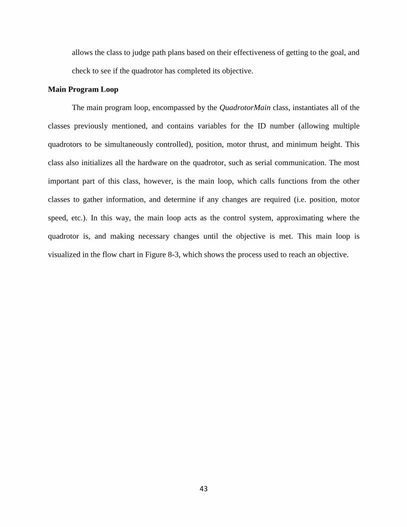
Main Program Loop
The main program loop, encompassed by the QuadrotorMain class, instantiates all of the
classes previously mentioned, and contains variables for the ID number (allowing multiple
quadrotors to be simultaneously controlled), position, motor thrust, and minimum height. This
class also initializes all the hardware on the quadrotor, such as serial communication. The most
important part of this class, however, is the main loop, which calls functions from the other
classes to gather information, and determine if any changes are required (i.e. position, motor
speed, etc.). In this way, the main loop acts as the control system, approximating where the
quadrotor is, and making necessary changes until the objective is met. This main loop is
visualized in the flow chart in Figure 8-3, which shows the process used to reach an objective.

44
Figure 8-3: Flow chart of the main quadrotor program.
8.2 Ground Robot Programming
The ground robot was programmed using the Player/Stage framework installed on the
Ubuntu operating system that is running on the robot. A user‟s laptop can connect wirelessly to
the robot and run scripts that control its actions, such as moving based on keyboard commands.
In this way, the ground robot can be controlled remotely using individual scripts from any
location where it has wireless access. However, if it does not have wireless access, programs can
still be executed on the ground robot, although such programs were beyond the scope of this
project.

45
The actual programming of the ground robot was relatively simple, since all the ground
robot had to do was move and communicate. The movement was already programmed into the
ground robot using pre-existing scripts in the Player/Stage framework. The communication from
the ground robot was more involved, and required programming the robot with knowledge of the
communication protocols that the quadrotor was using. With knowledge of the protocol, the
script could allow a user to input commands, or program the ground robot to create its own
commands. Since a USB XBee module was being used for transmission, the firmware was
installed on the robot, however the communication scripts were not working at the time this
report was written.
9. Test Setups
A thrust stand was developed to test the propellers and the motors. The measurements
acquired are thrust in grams, RPMs, and power, which are compared to the theoretical numbers.
With this information, the optimum propeller design is determined and the efficiency of the
system is calculated. A preliminary drawing of the design is shown in Figure 9-1.
Figure 9-1: Drawing of Test Stand
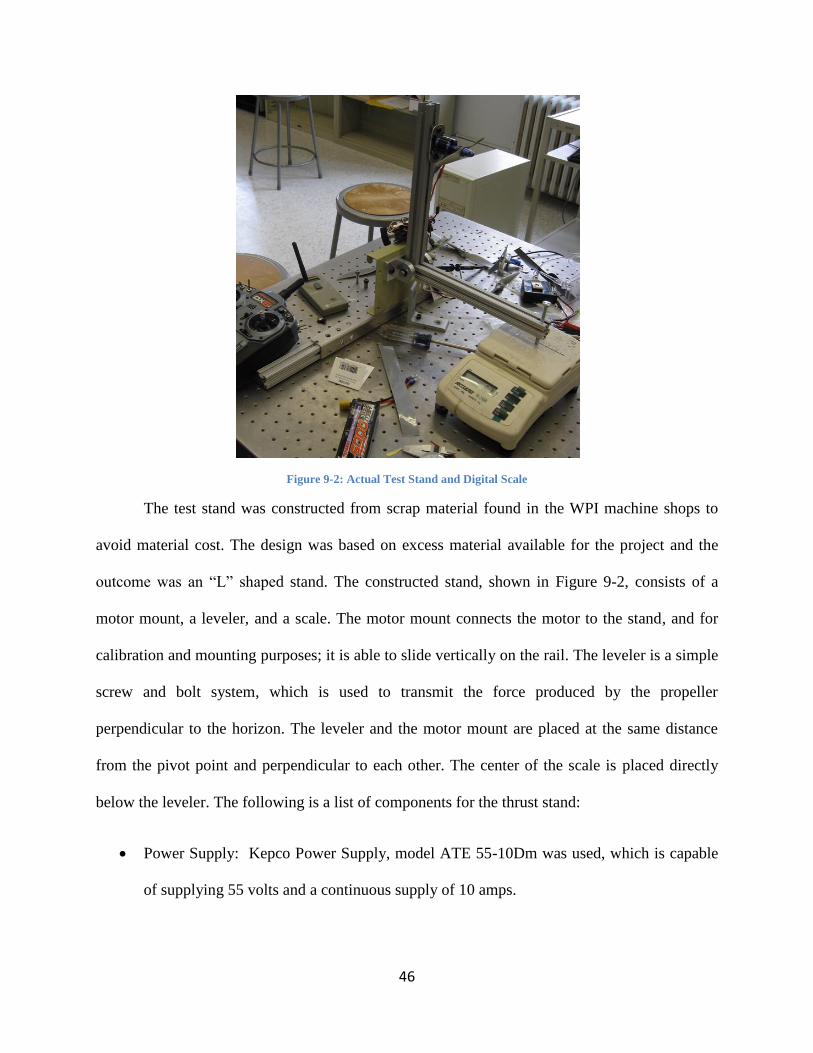
46
Figure 9-2: Actual Test Stand and Digital Scale
The test stand was constructed from scrap material found in the WPI machine shops to
avoid material cost. The design was based on excess material available for the project and the
outcome was an “L” shaped stand. The constructed stand, shown in Figure 9-2, consists of a
motor mount, a leveler, and a scale. The motor mount connects the motor to the stand, and for
calibration and mounting purposes; it is able to slide vertically on the rail. The leveler is a simple
screw and bolt system, which is used to transmit the force produced by the propeller
perpendicular to the horizon. The leveler and the motor mount are placed at the same distance
from the pivot point and perpendicular to each other. The center of the scale is placed directly
below the leveler. The following is a list of components for the thrust stand:
Power Supply: Kepco Power Supply, model ATE 55-10Dm was used, which is capable
of supplying 55 volts and a continuous supply of 10 amps.

47
RPM sensor: Ono Sokki HT-4100 Digital Tachometer was used. It beams a light to the
propeller, which has a reflective tape on one of the blades, and counts how many passes
the tape undergoes each second and displays it in revolutions per minute.
To calibrate the stand, a spring scale, the test stand scale, and an object of known mass were
used. To ensure that both scales were working properly and calibrated, the object was weighed
with the test stand scale and the spring scale (both scales should read the same). The motor was
set up on the stand and the spring scale was attached to the motor. The force applied to the spring
scale should read the same as the test stand scale. Figure 9-3 and the accompanying equations
exhibit this:
o
o
b
b
Fmotor
Fscale
A
Figure 9-3: Thrust Test Stand
48
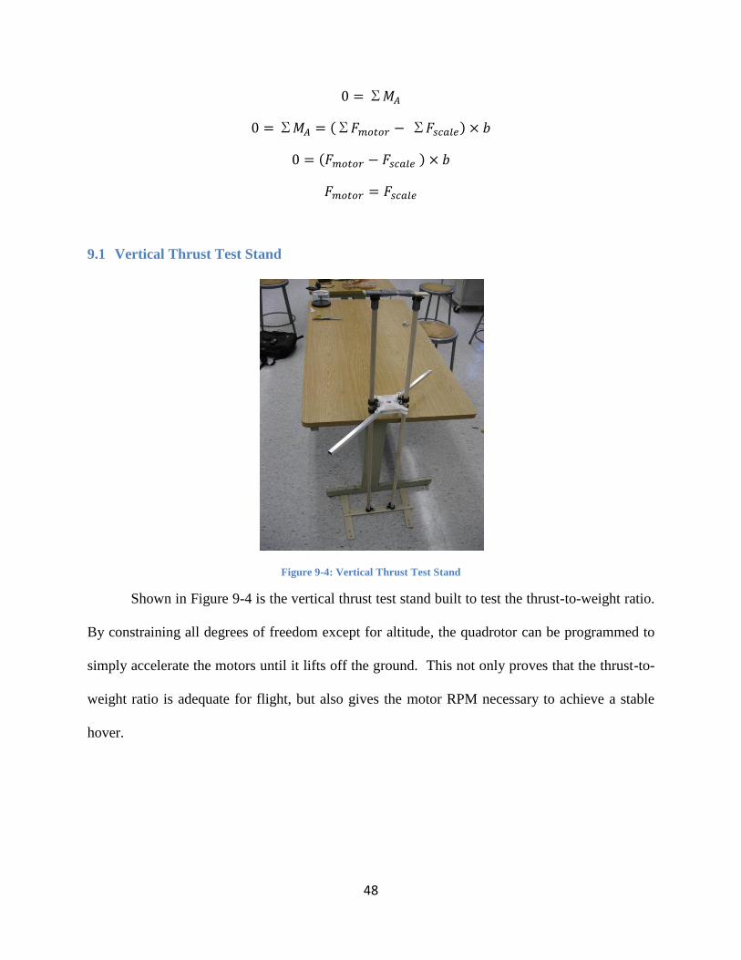
9.1 Vertical Thrust Test Stand
Figure 9-4: Vertical Thrust Test Stand
Shown in Figure 9-4 is the vertical thrust test stand built to test the thrust-to-weight ratio.
By constraining all degrees of freedom except for altitude, the quadrotor can be programmed to
simply accelerate the motors until it lifts off the ground. This not only proves that the thrust-to-
weight ratio is adequate for flight, but also gives the motor RPM necessary to achieve a stable
hover.
49
9.2 Sensor Testing
To ensure the sensors were providing accurate readings, tests were performed to confirm
that everything was working properly. The sensors that needed to be tested were the rangefinders
(both infrared and sonar), the IMU, the infrared detectors, and the Hall Effect switches.
Rangefinders
Testing the infrared and sonar rangefinders was identical, since both sensors serve the
same purpose. To test them, the output voltage was measured for an object at several distances,
from the sensor‟s minimum range to its maximum range. The more distances tested, the more
accurate the results would be, but for time purposes readings were only tested at every 10 cm.
The output voltage at each distance was recorded and graphed, and a polynomial approximation
of the curve was generated. The approximation was limited to a second order polynomial to cut
down on the math required by the processor. The approximation related distance to voltage, so
getting the inverse of that approximation would allow it relate voltage to distance. Using this
inverse, the voltage readings collected from each sensor could be related to the distance
measured at any given time.
Inertial Measurement Unit
The IMU required several tests to confirm its accuracy due to the presence of both
accelerometers and gyroscopes in it. To test the accelerometers, the output of each axis was read
at 1g, 0g, and -1g by orienting the axis being measured parallel or perpendicular to gravity. The
output at each orientation created the baseline of the positive, zero, and full negative output of
each axis at the given values. Additionally, the output from the accelerometers was being used to
approximate pitch and roll, meaning that a function linearizing the output had to be generated.
To do this, readings from the X and Y axes were measured at angles ranging from 0 degrees to

50
90 degrees in 5 degree increments. Similar to the method used for the rangefinder sensors, the
data was graphed, approximated, and inverted, resulting in an equation that related measured
acceleration to an angle for both the X and Y axes. The gyroscopes of the IMU were not tested
due to the limited resources available, but if they were tested, a turntable with a known velocity
could be used to ensure that the gyroscopes provide accurate readings at various known
velocities.
Infrared Detectors
Testing the infrared detectors involved reading the outputs for each individual sensor, and
measuring it against the outputs of all the other sensors. This was necessary to confirm that all
the sensors were working in a similar fashion and none were malfunctioning. This was
accomplished by providing similar input in the form of infrared light from LEDs and examining
the output for discrepancies. Several sensors were outputting slightly different values, which was
corrected by changing the resistance values in their circuits. However, overall the sensors
worked as expected.
Hall Effect Switches
The Hall Effect switches did not need much testing, only requiring the use of a magnet to
confirm that the output was toggled when a magnetic field was applied. However, the sensors did
require calibration to make the output of the toggled state detectable by the processor. In order to
achieve this, resistance values in the circuit were changed until the output was above the 2.5 volt
threshold the processor used to detect a digital state change.

51
10. Timeline
In September, a list of the electronics needed was drafted and ordered. Designs for the
quadrotor were begun while a fiberglass prototype was designed and prepared for testing. Near
the end of September, the electronics arrived and programming began for the quadrotor and the
processor and rangefinder sensors were implemented. Controls equations were difficult to
comprehend and took several months to understand. Most of October was spent continuing work
that was started in September.
During November, a final design was reached and the electronics had been prepared to
mount on the quadrotor. The propellers from the previous projects were tested and it was
determined that their type was suitable for the quadrotor, although there was some damage to a
couple, so new ones were ordered. A vertical thrust test stand was designed and constructed at
the end of November. An electronics board was created, and most of the electronics were
implemented onto it. The programming also progressed, with many of the planned classes being
implemented. In December, the electronics were mounted on the quadrotor. However, during its
first test, one of the chips started smoking and the test was aborted. Once the problem was fixed,
a simple hover test was attempted the day before winter break and led to the discovery that a
motor was faulty and failed to provide enough lift for the quadrotor to hover.
Beginning of January, a new motor was purchased and mounted on the quadrotor, and
testing then resumed. The electronics were fully implemented, as well as the majority of the
software. A complimentary filter was also implemented when efforts towards creating a working
Kalman filter did not yield results. After conducting several tests, issues concerning the battery
and communications between the control station and quadrotor arose. The communications
issues were resolved; however, battery issues resulted in a stand still for the testing. At this time

52
there were still no batteries, and the new batteries were still being shipped, which resulted in very
little progress and an inability to complete all the tasks at hand.
11. Final Results
Much was accomplished over the course of this project, even though the quadrotor was not
yet capable of autonomous hovering at the time this report was written. Electronic and power
issues prevented proper testing of the control equations governing the motion of the quadrotor.
While the structure of the quadrotor was developed and analyzed to demonstrate an airworthy
vehicle, the final frame was a departure from the original goals outlined at the beginning of the
project. The required systems for the operation of the quadrotor such as the processors for
enacting the control equations and the sensors for monitoring the flight conditions were
purchased and implemented on the system, however due to complexity of the relationships
between the individual components, troubleshooting the entire system became very tedious, and
when new parts were required long processing times for orders slowed progress. The
programming for basic attitude control using a complimentary filter and hovering using a PID
controller was written, however it was unable to be tested. The control equations and the
equations governing the implementation the Kalman filter that were needed to finalize the
programming for sustained autonomous flight were in a state of flux as of the end of the project.
The tie in of the ground robot into the system was achieved through the fabrication of a mounted
landing pad, the original goal of having the ground robot acting as the command station was as
of yet unrealized at the time this report was written.
53
One of our main objectives was to maximize the payload of the craft. A thrust test stand was
built in order to test motors and choose one that would provide us with the thrust needed to lift
the weight of our craft as well as provide the lift for an additional payload. Another objective
was to increase flight time, which was addressed by choosing a powerful battery that could
sustain a high power use over extender periods of time.
12. Reflections of Project
Our team was ambitious at the start of this project and with 7 members, we were
confident in our abilities to design a quadrotor and have it flying by the end of the 3 terms.
Having such a large group has its advantages and disadvantages. For one, the group was broken
up into specialized design groups to focus on one area of the project (i.e. electronics, controls,
dynamics, and structures). This enabled tasks to finish quicker and allowed more thorough
analysis to be done on each section. Provided everyone contributes equally and pulls their
weight in terms of taking initiative with assigned tasks, this method should work. However, we
were faced with the difficulty of organizing 7 people that have different schedules and priorities,
and often the design teams were scattered and inefficient. Working through this issue as a team,
we would meet at least a couple times a week. One was always an administrative meeting to
work through issues we were having, work on the report and/or presentations, and bring
everyone up to speed. Other meetings through the week were held in the lab where construction
and electronic implementation would take place. Further in the project, testing and
troubleshooting was done during those meetings.

54
The schedule set for the project was followed for the first term. The design was drafted
and a prototype was constructed immediately. Productivity slowly decreased over the next term
though, much due to the business in everyone‟s schedule and having to order/wait for parts to
arrive. Our first prototype was also scrapped because it did not meet the rigidity requirements
for the motors and the rest of the electronics. Once we realized that available materials would be
a better choice, a second prototype was made out of aluminum and Delrin plastic which in the
end was our final constructed design. Approximately mid-way through the project, the design
process slowed greatly, where only programming took place. This was mostly due to the fact
that all of the parts needed to do anything had not arrived. It was during this time though that
keeping the productivity and motivation high with the team became difficult. Not everyone
wanted to contribute equally and the overall relationship of the team was not as strong as it could
have been. This became the biggest challenge in the whole project process, staying focused and
reminding yourself that what you contribute is important.
As soon as all of the parts came in and the basic commands were programmed, testing
could be done. As the end of the project approached however, the quadrotor was only tested a
couple times and the report needed to be finished to complete the project. The last few weeks
leading up to the project deadline, the team wrapped up writing the report to present the design
process and although we may not have been successful in our initial goals, we completed the
design of an unmanned aerial vehicle, meeting at least part of the MQP requirement.
Overall, the large group for this project was difficult to manage and keep motivated. Our
recommendation for future projects in this topic area is to keep the group small and include
another Robotics/Computer Science student to assist in the electronics and programming for this
project. A smaller group would force those students to work on the project and create a less

55
conflicting atmosphere for group ideas, etc. Also, working on the Kalman filter early in the
process is vital to the success in the quadrotor‟s controls and as a whole, as it is required for a
successful flight.
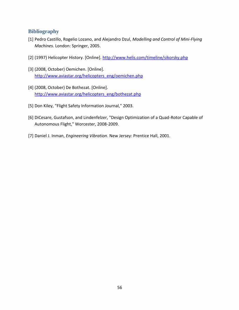
56
Bibliography
[1] Pedro Castillo, Rogelio Lozano, and Alejandro Dzul, Modelling and Control of Mini-Flying
Machines. London: Springer, 2005.
[2] (1997) Helicopter History. [Online]. http://www.helis.com/timeline/sikorsky.php
[3] (2008, October) Oemichen. [Online].
http://www.aviastar.org/helicopters_eng/oemichen.php
[4] (2008, October) De Bothezat. [Online].
http://www.aviastar.org/helicopters_eng/bothezat.php
[5] Don Kiley, "Flight Safety Information Journal," 2003.
[6] DiCesare, Gustafson, and Lindenfelzer, "Design Optimization of a Quad-Rotor Capable of
Autonomous Flight," Worcester, 2008-2009.
[7] Daniel J. Inman, Engineering Vibration. New Jersey: Prentice Hall, 2001.
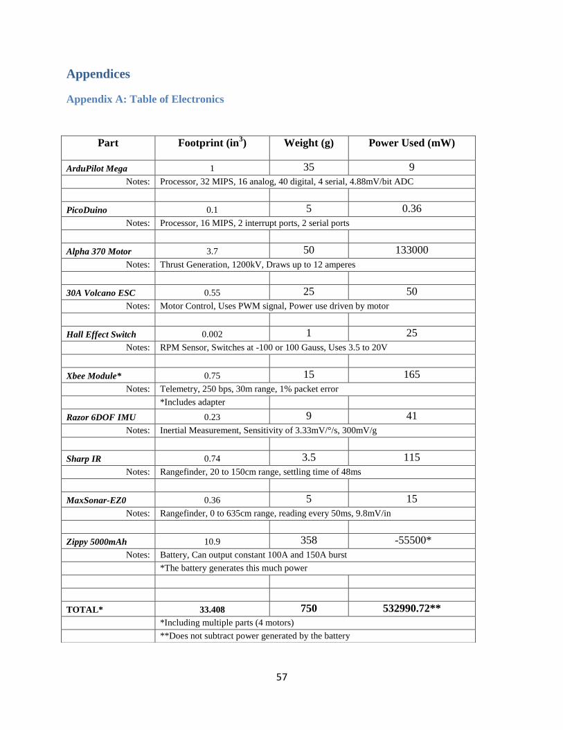
57
Appendices
Appendix A: Table of Electronics
Part Footprint (in3) Weight (g) Power Used (mW)
ArduPilot Mega 1 35 9
Notes: Processor, 32 MIPS, 16 analog, 40 digital, 4 serial, 4.88mV/bit ADC
PicoDuino 0.1 5 0.36
Notes: Processor, 16 MIPS, 2 interrupt ports, 2 serial ports
Alpha 370 Motor 3.7 50 133000
Notes: Thrust Generation, 1200kV, Draws up to 12 amperes
30A Volcano ESC 0.55 25 50
Notes: Motor Control, Uses PWM signal, Power use driven by motor
Hall Effect Switch 0.002 1 25
Notes: RPM Sensor, Switches at -100 or 100 Gauss, Uses 3.5 to 20V
Xbee Module* 0.75 15 165
Notes: Telemetry, 250 bps, 30m range, 1% packet error
*Includes adapter
Razor 6DOF IMU 0.23 9 41
Notes: Inertial Measurement, Sensitivity of 3.33mV/°/s, 300mV/g
Sharp IR 0.74 3.5 115
Notes: Rangefinder, 20 to 150cm range, settling time of 48ms
MaxSonar-EZ0 0.36 5 15
Notes: Rangefinder, 0 to 635cm range, reading every 50ms, 9.8mV/in
Zippy 5000mAh 10.9 358 -55500*
Notes: Battery, Can output constant 100A and 150A burst
*The battery generates this much power
TOTAL* 33.408 750 532990.72**
*Including multiple parts (4 motors)
**Does not subtract power generated by the battery
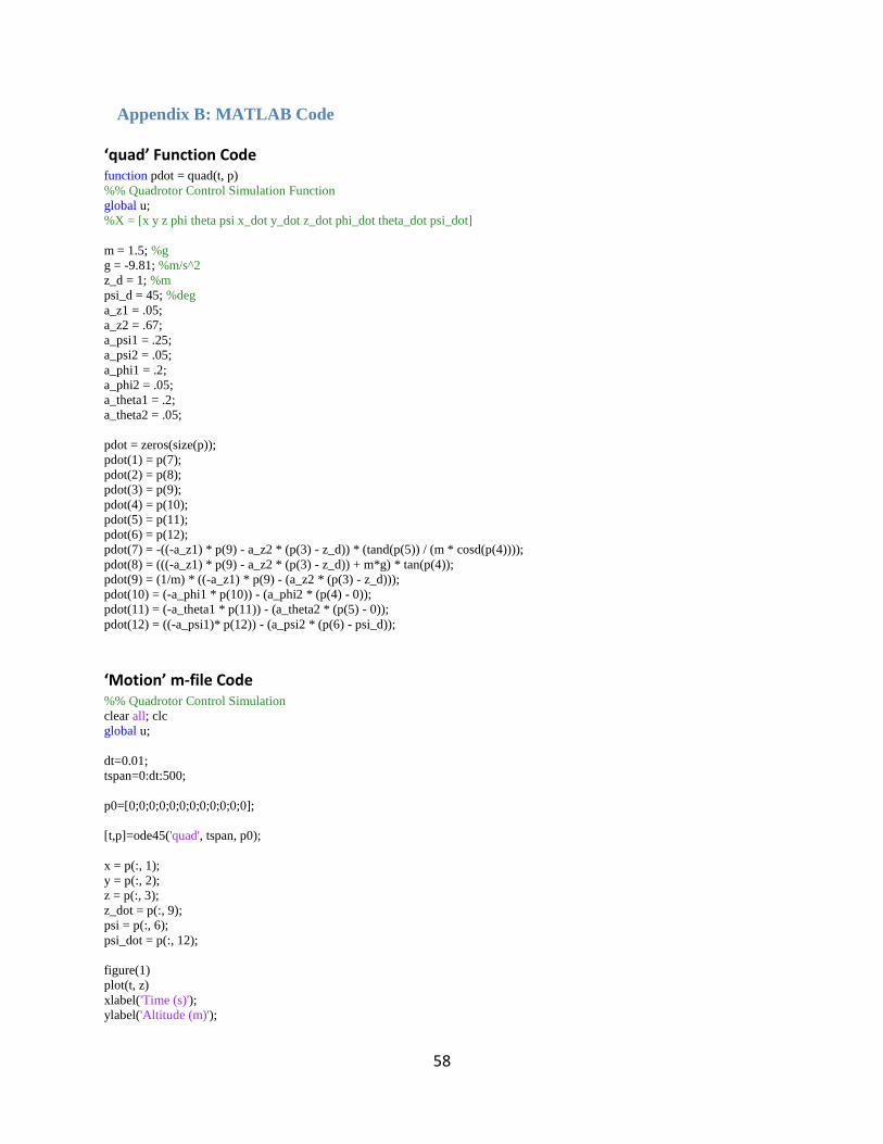
58
Appendix B: MATLAB Code
‘quad’ Function Code function pdot = quad(t, p)
%% Quadrotor Control Simulation Function
global u;
%X = [x y z phi theta psi x_dot y_dot z_dot phi_dot theta_dot psi_dot]
m = 1.5; %g
g = -9.81; %m/s^2
z_d = 1; %m
psi_d = 45; %deg
a_z1 = .05;
a_z2 = .67;
a_psi1 = .25;
a_psi2 = .05;
a_phi1 = .2;
a_phi2 = .05;
a_theta1 = .2;
a_theta2 = .05;
pdot = zeros(size(p));
pdot(1) = p(7);
pdot(2) = p(8);
pdot(3) = p(9);
pdot(4) = p(10);
pdot(5) = p(11);
pdot(6) = p(12);
pdot(7) = -((-a_z1) * p(9) - a_z2 * (p(3) - z_d)) * (tand(p(5)) / (m * cosd(p(4))));
pdot(8) = (((-a_z1) * p(9) - a_z2 * (p(3) - z_d)) + m*g) * tan(p(4));
pdot(9) = (1/m) * ((-a_z1) * p(9) - (a_z2 * (p(3) - z_d)));
pdot(10) = (-a_phi1 * p(10)) - (a_phi2 * (p(4) - 0));
pdot(11) = (-a_theta1 * p(11)) - (a_theta2 * (p(5) - 0));
pdot(12) = ((-a_psi1)* p(12)) - (a_psi2 * (p(6) - psi_d));
‘Motion’ m-file Code %% Quadrotor Control Simulation
clear all; clc
global u;
dt=0.01;
tspan=0:dt:500;
p0=[0;0;0;0;0;0;0;0;0;0;0;0];
[t,p]=ode45('quad', tspan, p0);
x = p(:, 1);
y = p(:, 2);
z = p(:, 3);
z_dot = p(:, 9);
psi = p(:, 6);
psi_dot = p(:, 12);
figure(1)
plot(t, z)
xlabel('Time (s)');
ylabel('Altitude (m)');
59
figure(2)
plot(t, z_dot)
xlabel('Time (s)');
ylabel('Z-Velocity (m/s)');
figure(3)
plot(t, psi)
xlabel('Time (s)');
ylabel('Psi Angle (Deg)');
figure(4)
plot(t, psi_dot)
xlabel('Time (s)');
ylabel('Psi Anglular Velocity (Deg/s)');