Embed Size (px)
Citation preview

High speed railways: pantograph and overhead
lines modelling and simulation
G. Diana, S. Bruni, A. Collina, F. Fossati, F. Resta
Politecnico diMilano, Department ofMech. Eng.,
f .zza Z. Fmcz J2, 207 JJ, M// o, / /y,Email: [email protected]
Abstract
The paper describes some aspects of the researches carried out on thesubject of pantograph-catenary interaction at the Department of Mech.Eng. of Politecnico di Milano. In particular a mathematical model ofpantograph and overhead equipment dynamic interaction has beendeveloped, and validated by means of comparison with experimental
results. The model has been used for the design of the italian high speedline, and for preliminary studies on the subject of active controlledpantograph.
1. Introduction
Current collection from overhead catenary represents one of the majorproblems related to the development of high speed rail systems. This taskis performed by means of one or more collector strips mounted on apantograph. As the speed of the train increases over 180-200 km/h, thedynamics of the coupled system pantograph-overhead equipment (OHE)plays a fundamental role in the quality of the current collection: it followsthat static criteria are not suitable for the design of high speed catenaryand pantograph. As an example, the adoption of a stitch catenary,equipped with "Y" suspension, or the adoption of the contact wire pre-sag, depend on quasi-static considerations. Their use tends to beabandoned on new design catenaries, [1], [2], since their effectivenesstends to be of less importance at high speed.
The study of the dynamic interaction between pantograph and OHEcan be performed by means of mathematical models [6]: in the lastdecade, several computer codes have been developed by railway
Transactions on the Built Environment vol 34, © 1998 WIT Press, www.witpress.com, ISSN 1743-3509
848 Computers in Railways
companies ([3]), university research centres ([2] and [5]), and pantographmanufacturers ([4]).
A simulation program can be used for the optimisation (in the designstage) and final verification of new OHEs and pantographs, for theevaluation of service interoperability and for evaluating the performances
of active controlled pantographs. This last topic is related to serviceinteroperability: active control can help to optimise pantographperformance with respect to different catenaries.
Pantograph-OHE dynamic interaction is one of the research fieldsdeveloped at Politecnico di Milano, Department of MechanicalEngineering, including mathematical modelling, laboratory and on-linetests. A mathematical model has been improved and validated takingadvantage from laboratory test on pantographs and droppers, and on-linetests on high speed and ordinary lines. The development of the simulationcode has been carried out in co-operation with Italferr (engineeringcompany of Italian State railway F.S.) and ABB-SAE Sadelmi (OHEmanufacturer). More recently researches have also been conducted on the
topic of active controlled pantograph [9], aimed to investigating ondifferent control strategies and their applicability. The paper describes themain results and the guidelines of future researches of research in the areaof mathematical modelling and control.
2. The mathematical model
The mathematical model of pantograph-OHE dynamic interaction heredescribed has been developed mainly for catenary design andverification, and takes into account for:- catenary geometry (dropper location, double/single contact wire);- flexural stiffness of the contact wire, particularly important incorrespondence of the singular points (dropper and registration arms);- non linear behaviour of the droppers, due to slackening, which isessential for a realistic simulation of the contact force.A finite element schematisation of the catenary is adopted, whiledropper's behaviour is included by means of non linear forces, function ofcatenary motion. Pantograph behaviour is reproduced with a lumpedparameters model, which has proved to be adequate up to 30 Hz.
2.1 Mathematical model of the catenary
The OHE schematisation can be restricted to the vertical plane, orextended in 3-D, if the zig-zag location of the contact wire is needed in
Transactions on the Built Environment vol 34, © 1998 WIT Press, www.witpress.com, ISSN 1743-3509

Computers in Railways 849
the analysis. Bernoulli-Euler 2-node tensioned beam element are adopted
for contact wire, messenger wire, and auxiliary wires, if present: the
adopted length of each element is 1 4-1. 5m. Boundary conditions are set
up by means of springs, as well as for supports at each span, whileregistration arm is reproduced with a lumped mass. A typical number ofspan ranges from 6 to 10. The equations of motion are written through alagrangian approach, around the static equilibrium position:
where Xc collects the d.o.f of the catenary, [Me], [Re] and [KJ arerespectively mass, damping and stiffness matrices, being
[Rc]=a[Mc]+p[KJ. The term F p and F , are respectively the generalisedforce vectors related to the contact force exchanged between pantographan contact wire and to the non linear droppers' behaviour. Non linearitydue to droppers can be included directly by means of the relationshipbetween force and relative displacement obtained from laboratory tests,or by means of equivalent mechanical models, used for special kind ofdropper [10] which exhibits a hysteretic behaviour.
2.2 Mathematical model of the pantograph
A lumped parameters scheme of the pantograph is adopted, based on alinear representation of the pantograph, in the neighbourhood of itsworking position. More sophisticated models can be adopted if theinvestigation involves a frequency range wider than 0-30 Hz. In this casethe key element is model of the collector head, whose flexural resonanceshave to be taken into account, with a f.e.m. model or with a modal
approach. Moreover, a full f.e.m.schematisation of the entirepantograph is required only if thestress in pantograph members areneeded. The lumped parametersschematisation, shown in Figure 1for the ATR90 pantograph.Besides the d.o.f. representing thetwo collector heads and the framemotion, two supplementary d.o.f.related to the point of contact areincluded (figure 1).The equations of motion of thepantograph are the following:
ocrtact
derrHts
Cdlectcrhead
frame
V
Figure 1 Lumped parameters modelof the pantograph
Transactions on the Built Environment vol 34, © 1998 WIT Press, www.witpress.com, ISSN 1743-3509

850 Computers in Railways
(2)
where Xp collect the d.o.f. of the pantograph, and r\ the d.o.f. of thecontact points, which follow the motion of the contact wire.
2.3 Model of pantograph-OHE interaction
The partitioning of eq (2), leads to the following equation, where the firstone refers to the motion of the pantograph d.o.f., and the second one isused for the calculation of the contact force:
,~
The motion of each contact point is a function of catenary motion, and ofthe location 5, of the collector head along the k-th finite element of thecontact wire. In particular, in the vertical plane, the motion of the contactpoint moving in longitudinal direction with a speed V, is expressedthrough the shape function of the finite element:
being x% the vector of the nodal d.o.f. of the k-th finite element. Insertingeq.(4) into the first of eq.(3), the generalised forces acting on thepantograph can be expressed as a function of catenary motion, while fromthe second of eq.(3), the contact forces are expressed as a function of bothpantograph and catenary motion. Finally, nodal forces on the catenary,corresponding to the contact forces Fr| applied to the k-th finite elementat the contact wire are calculated through the shape function of the finiteelement. Putting together eqs.(l), (3) and (4), the following set ofequations of motion are obtained for the catenary and the pantograph.The forcing terms F^p and Fpc act as coupling terms between the two setsof equations and therefore include in the model the effects of pantograph-OHE interaction:
The equations of motion are integrated in the time domain, by means of
Transactions on the Built Environment vol 34, © 1998 WIT Press, www.witpress.com, ISSN 1743-3509
Computers in Railways 851
an iterative procedure [7].
3. Comparison with experimental results
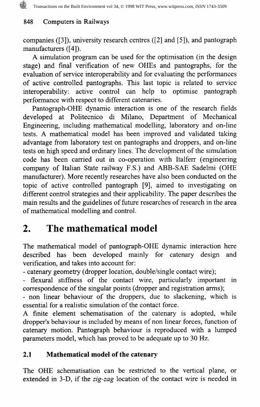
Results of experimental on-line tests have been used in order to obtain avalidation of the mathematical model. In this section, some comparisonsbetween numerical results and measurements carried out in 1996 on thethe FS line "Direttissima" connecting Florence to Rome will bepresented. Tests have been carried out at different train speeds, rangingfrom 150 to 280km/h, with an instrumented ETR500 test train, which letalso the measurements of contact force, performed by FS.As a first example, the time history of the vertical displacement of thecontact wire at the suspension, is shown in figure 2. The two maximumvalues correspond to the transit of the first pantograph (129N preload)and the second one (2 ION preload)..
[mm]
0.00 10.00 20.00 30.00
Figure 2: Vertical displacement of contact wire under suspension: left(a), measurement, right (b), simulation.
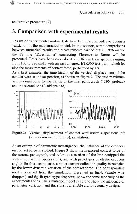
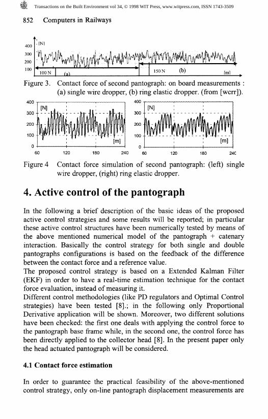
As an example of parametric investigation, the influence of the dropperson contact force is studied: Figure 3 show the measured contact force ofthe second pantograph, and refers to a section of the line equipped thewith single wire droppers (left), and with prototypes of elastic droppers(right); for this second case, a better current collection quality is revealedby the lower dynamic variation of the contact force. The correspondingresults obtained from the simulation, presented in fig.4a (single wiredroppers) and fig.4b (prototype droppers), show the same tendency as theexperimental ones. The simulation model is able to show the influence ofparameter variation, and therefore is a reliable aid for catenary design.
Transactions on the Built Environment vol 34, © 1998 WIT Press, www.witpress.com, ISSN 1743-3509
852 Computers in Railways
400300200100
. nsn
lOONM «niA4A%U ^ #K ^ kV#% % #Y 4\ |i In/ " I'* " fc-p I ?
'50N (b) ,ml
Figure 3. Contact force of second pantograph: on board measurements :(a) single wire dropper, (b) ring elastic dropper, (from [wcrr]).
400-, , , « 400-
60 120 180 24C
Figure 4 Contact force simulation of second pantograph: (left) single
wire dropper, (right) ring elastic dropper.
4. Active control of the pantograph
In the following a brief description of the basic ideas of the proposedactive control strategies and some results will be reported; in particularthese active control structures have been numerically tested by means ofthe above mentioned numerical model of the pantograph + catenaryinteraction. Basically the control strategy for both single and doublepantographs configurations is based on the feedback of the differencebetween the contact force and a reference value.The proposed control strategy is based on a Extended Kalman Filter(EKF) in order to have a real-time estimation technique for the contactforce evaluation, instead of measuring it.Different control methodologies (like PD regulators and Optimal Controlstrategies) have been tested [8].; in the following only ProportionalDerivative application will be shown. Moreover, two different solutionshave been checked: the first one deals with applying the control force tothe pantograph base frame while, in the second one, the control force hasbeen directly applied to the collector head [8]. In the present paper onlythe head actuated pantograph will be considered.
4.1 Contact force estimation
In order to guarantee the practical feasibility of the above-mentionedcontrol strategy, only on-line pantograph displacement measurements are
Transactions on the Built Environment vol 34, © 1998 WIT Press, www.witpress.com, ISSN 1743-3509
Computers in Railways 853
supposed available to controller, neglecting any overhead line measured
data or contact force measurements. More in details the contact force isevaluated by means of the EKF [8].
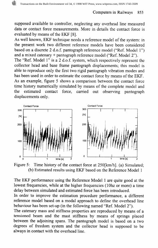
As well known, EKF technique needs a reference model of the system: inthe present work two different reference models have been consideredbased on a discrete 2 d.o.f. pantograph reference model ("Ref. Model 1")and a mixed catenary + pantograph reference model ("Ref. Model 2").The "Ref. Model 1" is a 2 d.o.f. system, which respectively represent thecollector head and base frame pantograph displacements; this model isable to reproduce only the first two rigid pantograph vibration modes andhas been used in order to estimate the contact force by means of the EKF.As an example, figure 5 shows a comparison between the contact forcetime history numerically simulated by means of the complete model andthe estimated contact force, carried out observing pantographdisplacements only.
Contact Force Contact Force
100
time [s] ime [s]
Figure 5: Time history of the contact force at 250[km/h]. (a) Simulated;(b) Estimated results using EKF based on the Reference Model 1
The EKF performance using the Reference Model 1 are quite good at thelowest frequencies, while at the higher frequencies (10hz or more) a timedelay between simulated and estimated force has been introduced.In order to improve the estimation procedure performance, a differentreference model based on a modal approach to define the overhead linebehaviour has been set-up (in the following named "Ref. Model 2").The catenary mass and stiffness properties are reproduced by means of atensioned beam and the mast stiffness by means of springs placedbetween the adjoining spans. The pantograph model is based on a twodegrees of freedom system and the collector head is supposed to bealways in contact with the overhead line.
Transactions on the Built Environment vol 34, © 1998 WIT Press, www.witpress.com, ISSN 1743-3509
854 Computers in Railways
Also in this case, the contact force F& has been included in the Ref. Model2 extended state vector, witch contains the base frame pantographdisplacement and velocity and the modal co-ordinates describing theoverhead line dynamics.
Middle span displacement Middle span displacement
0.08 -
0.04 -
0.04 -
0.08 -
3 time [s] 4 3 time [s] 4
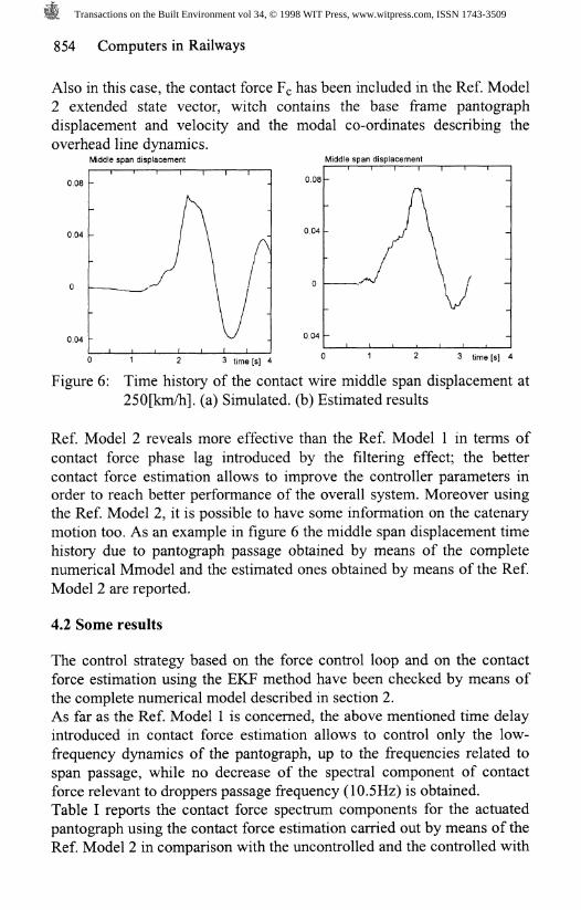
Figure 6: Time history of the contact wire middle span displacement at250[km/h]. (a) Simulated, (b) Estimated results
Ref. Model 2 reveals more effective than the Ref. Model 1 in terms ofcontact force phase lag introduced by the filtering effect; the bettercontact force estimation allows to improve the controller parameters inorder to reach better performance of the overall system. Moreover usingthe Ref. Model 2, it is possible to have some information on the catenarymotion too. As an example in figure 6 the middle span displacement timehistory due to pantograph passage obtained by means of the completenumerical Mmodel and the estimated ones obtained by means of the Ref.Model 2 are reported.
4.2 Some results
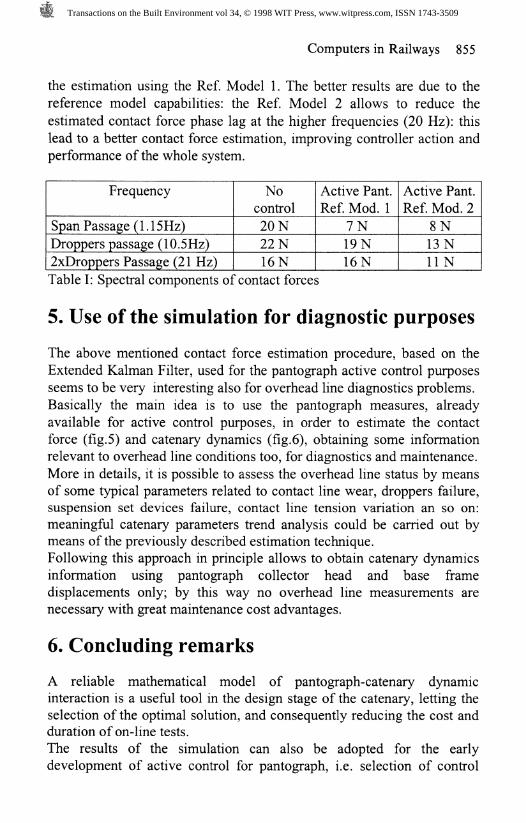
The control strategy based on the force control loop and on the contactforce estimation using the EKF method have been checked by means ofthe complete numerical model described in section 2.As far as the Ref. Model 1 is concerned, the above mentioned time delayintroduced in contact force estimation allows to control only the low-frequency dynamics of the pantograph, up to the frequencies related tospan passage, while no decrease of the spectral component of contactforce relevant to droppers passage frequency (10.5Hz) is obtained.Table I reports the contact force spectrum components for the actuatedpantograph using the contact force estimation carried out by means of theRef. Model 2 in comparison with the uncontrolled and the controlled with
Transactions on the Built Environment vol 34, © 1998 WIT Press, www.witpress.com, ISSN 1743-3509
Computers in Railways 855
the estimation using the Ref. Model 1. The better results are due to the
reference model capabilities: the Ref. Model 2 allows to reduce the
estimated contact force phase lag at the higher frequencies (20 Hz): thislead to a better contact force estimation, improving controller action andperformance of the whole system.
Frequency
Span Passage (l.lSHz)Droppers passage (10.5Hz)
2xDroppers Passage (21 Hz)
Nocontrol
20 N
22 N
16N
Active Pant.Ref. Mod. 1
7N
19N
16N
Active Pant.Ref. Mod. 2
8N
13 N
UNTable I: Spectral components of contact forces
5. Use of the simulation for diagnostic purposes
The above mentioned contact force estimation procedure, based on theExtended Kalman Filter, used for the pantograph active control purposesseems to be very interesting also for overhead line diagnostics problems.Basically the main idea is to use the pantograph measures, alreadyavailable for active control purposes, in order to estimate the contactforce (fig.5) and catenary dynamics (fig.6), obtaining some informationrelevant to overhead line conditions too, for diagnostics and maintenance.
More in details, it is possible to assess the overhead line status by meansof some typical parameters related to contact line wear, droppers failure,suspension set devices failure, contact line tension variation an so on:meaningful catenary parameters trend analysis could be carried out bymeans of the previously described estimation technique.Following this approach in principle allows to obtain catenary dynamicsinformation using pantograph collector head and base framedisplacements only; by this way no overhead line measurements arenecessary with great maintenance cost advantages.
6. Concluding remarks
A reliable mathematical model of pantograph-catenary dynamicinteraction is a useful tool in the design stage of the catenary, letting theselection of the optimal solution, and consequently reducing the cost andduration of on-line tests.The results of the simulation can also be adopted for the earlydevelopment of active control for pantograph, i.e. selection of control
Transactions on the Built Environment vol 34, © 1998 WIT Press, www.witpress.com, ISSN 1743-3509

856 Computers in Railways
strategy and evaluation of its performance.The simulation model has the potentialities of being adopted also fordiagnostics and maintenance pourposes, such as the evaluation ofmedium wear rate of the contact wire. The last topic could be of greatimportance in view of a modern approach to OHE maintenance.
References
[1] Descourbes M., 10 ans de progres: la catenaire, RVGCF, N.10,octobre, 1991.
[2] G. Diana, M. Falco, S. Fasciolo, V. Morelli, Experimental andnumerical investigation on the dynamic behaviour of the catenary forAV italian railway line, WCRR '97, Nov. 1998, Florence, Italy.
[3] G. A. Scott, M. Cook, Extending the limits of pantograph overhead
line performance, IMechE, C514/05 3.[4] Brodkorb A., Semrau M., Simulationsmodell des Systems
Oberleitungeskettenwerk und Stromabnehemer, Elektrische Bahnen,N.91,pp.l05-113, 1993.
[5] Nowak B., Link M., Zur Optimierung der dynamischen Parameterdes ICE-Stromabnehmers durch Simulation der Fahradynamik, VDIBericthe 635, pp. 147-166, 1987.
[6] Poetsch G. et al, Pantograph/Catenary Dynamics ands Control,Vehicle System Dynamics, Vol. 28, N2-3, Swets & ZeitlingerPublishers, pp. 159-195, August 1998.
[7] Diana G., et al. Research on the dynamic behaviour of thepantograph-catenary system, Internal Report of Politecnico diMilano, Department of Mechanics, Milano, October 1988 (in italian)
[8] G. Diana, F. Fossati, F. Resta, A. Collina, Active control of highspeed train pantograph. Ill"* Int. Conf. on Motion and Vibr. Control,Chiba, 1-6 sept., 1996, Japan.
[9] G. Diana, F. Fossati, F. Resta, High speed railway: collectingpantographs active control and overhead lines diagnostic solutions,on publication on Vehicle System Dynamics, Swets & ZeitlingerPublishers
[10] M. Bocciolone et al., New catenary components tested for the AVitalian railway line: damped elastic droppers, World Rail Congress,WCRR '97, 16-19 Nov, 1998, Florence, Italy.
Transactions on the Built Environment vol 34, © 1998 WIT Press, www.witpress.com, ISSN 1743-3509