Embed Size (px)
Citation preview


I
Abstract
Face Detection has been applied in many fields such as surveillance, human machine
interaction, entertainment and health care. Two main reasons for extensive attention on
this typical research domain are: 1) a strong need for the face recognition system is
obvious due to the widespread use of security, 2) face recognition is more user friendly
and faster since it almost requests the users to do nothing.
The system is based on ARM Cortex-A8 development board, including transplantation of
Linux operating system, the development of drivers, detecting face by using face class
Haar feature and Viola-Jones algorithm. In the paper, the face Detection system uses the
AdaBoost algorithm to detect human face from the frame captured by the camera. The
paper introduces the pros and cons between several popular images processing algorithm.
Facial expression recognition system involves face detection and emotion feature
interpretation, which consists of offline training and online test part. Active shape model
(ASM) for facial feature node detection, optical flow for face tracking, support vector
machine (SVM) for classification is applied in this research.

II
Acknowledgements
I would first like to express my sincerest gratitude to my advisor, Dr. Xinming Huang, for
all the support and guidance from the onset of my experience at Worcester Polytechnic
Institute. He has fund of knowledge in Electrical Engineering and gives me more
instruction in Embedded System Design. His technical expertise and visionary leadership
has significantly guided my research work and career development. I attribute the level of
my master degree to his encouragement and effort and without him in this thesis, too,
would not have been completed or written.
Besides my advisor, I would like to thank the rest of my thesis committee: Prof. Lifeng
Lai and Prof. Taskin Padir, for their encouragement and insightful comments.

III
Dedication
This thesis is dedicated to my parents Qingguang Zhou and Dingxiang Xu.

IV
Contents
Abstract ........................................................................................................................................... I
Acknowledgements ....................................................................................................................... II
List of Figures .............................................................................................................................. VI
List of Tables .............................................................................................................................. VII
1. Overview ................................................................................................................................. 1
1.1 Face Detection ................................................................................................................. 1
1.2 Face Detection System Background ............................................................................. 2
1.3 Thesis Contribution ....................................................................................................... 6
1.4 Thesis Organization ....................................................................................................... 7
2. Face Detection Method .......................................................................................................... 8
2.1 Face Detection procedure .............................................................................................. 8
2.2 Feature Computation ..................................................................................................... 8
2.2.1 Integral Image ............................................................................................................... 8
2.2.2 Image Pyramid ............................................................................................................ 11
2.3 Feature Selection .......................................................................................................... 12
2.4 Real-Time solution ....................................................................................................... 17
2.4.1 The Attentional Cascade ...................................................................................... 17
2.4.2 Cascade of Classifiers Training ........................................................................... 18
2.4.3 Viola-Jones algorithm summary ......................................................................... 19
3 Development of Face Detection Platform .......................................................................... 21
3.1 Hardware Overview ..................................................................................................... 21
3.2 OMAP ............................................................................................................................ 21
3.2.1 Gumstix Overo Board........................................................................................... 21
3.2.2 Gumstix Overo Expansion ................................................................................... 23
3.3 System Requirement .................................................................................................... 24
3.3.1 Operating System Development .......................................................................... 24
3.3.2 Ubuntu ................................................................................................................... 24
3.3.3 Hardware Framework .......................................................................................... 25
4. Development of Facial Expression Recognition ................................................................ 27
4.1 Background ................................................................................................................... 27
4.2 Face Expression Recognition Process ......................................................................... 28
4.3 Face Expression Recognition Overview ..................................................................... 29
4.4 Face Feature Detector .................................................................................................. 30

V
4.4.1 MUCT Database.................................................................................................... 30
4.4.2 ASM ........................................................................................................................ 31
4.4.3 Procrustes analysis ................................................................................................ 32
4.4.4 PCA ........................................................................................................................ 32
4.4.5 Feature Point Detector ......................................................................................... 33
4.5 Feature Displacement .................................................................................................. 33
4.5.1 Face Expression Representation .......................................................................... 34
4.5.2 Face feature tracking ............................................................................................ 34
4.5.3 Optical Flow .......................................................................................................... 35
4.5.4 Cohn-Kanade database (CK+) ............................................................................ 36
4.5.5 Face feature displacement training ..................................................................... 37
4.5.6 SVM ........................................................................................................................ 40
5. Evaluation and Conclusion ................................................................................................. 42
5.1 Evaluation ..................................................................................................................... 42
5.2 Conclusion ..................................................................................................................... 43
Reference ...................................................................................................................................... 45
Vita ................................................................................................................................................ 49

VI
List of Figures
Figure 1.1: Audiences undergo identification checks at face recognition checkpoints before
entering the National Stadium on August 8, 2008. [Photo: Chinese Academy of Sciences] . 2
Figure 1.2: Face Detection Classification [14] . ............................................................................. 4
Figure 2.1: Three types of rectangle features. The sum of the pixels which lie in the white
rectangles are subtracted from the sum of pixels in the grey rectangles. (A) and (B) show
Two-rectangle features. (C) shows a three-rectangle feature. (D) shows a four-rectangle
feature[4]. ................................................................................................................................ 8
Figure 2.2: The value of the integral image at point (x,y) is the sum of all the pixels above and to
the left. [4] ............................................................................................................................... 9
Figure 2.3: The sum of the pixels within rectangle D can be computed with four array references.
For example, ii(x2,y2) = sum(A) + sum(B),in this case, Sum(D)=ii(x4,y4)+ii(x1,y1)-
ii(x2,y2)-ii(x3,y3) [4]. ........................................................................................................... 10
Figure 2.4: Two-Rectangle Features: ............................................................................................ 10
Figure 2.5: Gaussian Pyramid. Each layer is numbered from bottom to top, so layer (i+1) is
smaller than layer(i). [img.html] ........................................................................................... 12
Figure 2.6: Combinations of all possible locations, scales of rectangle-features are huge [10]. .. 13
Figure 2.7: Example of Relevant Feature of Human face, measuring the difference in intensity
between the region of nose and cheeks. [10] ........................................................................ 14
Figure 2.8: The Strong classifier is a linear combination of “weak” classifiers. [10] ................. 14
Figure 2.9: 200-feature classifier curve of receiver operating characteristic (ROC) [4]. ............ 16
Figure 2.10: Relevant good features in Adaboost [4]. ................................................................. 17
Figure 2.11: Cascade consists of several classifiers. Failure examples will be discarded, only the
“potential” examples are able to reach the next layer for “harder” detection [4]. ................ 18
Figure 2.12: Adaboost Face Detection Framework ...................................................................... 20
Figure 3.1:Gumstix Overo FireSTORM COM ............................................................................. 22
Figure 3.2: Gumstix Tobi Expansion Board ................................................................................. 23
Figure 3.3: Hardware Design of Embedded Face Detection System ............................................ 26
Figure 3.4: Hardware Design of Embedded Face Detection System ............................................ 26
Figure 4.1: Facial expression recognition process (Note: image face is from Cohn-Kanade
database) ............................................................................................................................... 29
Figure 4.2: Face Expression Recognition System ........................................................................ 30
Figure 4.3: The five cameras and their relationship to the subject’s face. .................................... 31
Figure 4.4: From left to right, raw data, translation, rotation, scale ............................................. 32
Figure 4.5: Landmarks show face feature in the image ................................................................ 33
Figure 4.6: Face feature nodes displacement reveal Expression motion ...................................... 34
Figure 4.7: Face detector fails to detect and locate feature nodes in peak expression. Mouth and
jaw area is messed up. ........................................................................................................... 35
Figure 4.8: Face feature tracking from left to right, up to down. ................................................. 37
Figure 4.9: Face features are represented by Nodes displacement for Emotion1 ......................... 38
Figure 4.10: Seven Emotion Feature Nodes displacement model in same scale .......................... 39
Figure 4.11: The optimal separating hyperplanes maximize the margin of the training data [44].
............................................................................................................................................... 40

VII
List of Tables
Table 1: List of Action Units and Action Descriptors (with underlying facial muscles) [41]. ..... 28
Table 2: The facial expression synthesis rules [34]. ..................................................................... 28
Table 3: Face features are represented by Nodes .......................................................................... 38
Table 4: Performance of Face Expression Recognition System with different sample rate. ........ 43

1
1. Overview
1.1 Face Detection
Face detection technology, dealing with identification and localization of faces from image
or video frame, was first developed in 1970s. Since face detection is rigidly restricted to the
plain backgound and frontal face of the image at a earlier time, the use of face detection is
quite limited until the past decade since great development of face detection has been made.
[14]. Nowadays widely use of face detection has gained great attention over the world, some
applications developed from face detection are promising and encouraging including
surveillance systems, photography, interaction between human and computer etc.
In biological recognition field Face Detection is playing a big role since Face Recognition is
a major technology which is competing with fingerprint recognition. Face detection is the
used to extract the face features and “chop” the face area out of original image prior to face
recognition.
Face detection growth has also prompted the surveillance and safety system to a higher level.
Face Recognition System turns out to be a great solution to society issue, such as security,
caused by fast-growing human population and activities (Figure1.1). Embedded face
recognition system will meet the great the need for safety and surveillance use.
Even though face could easily be identified by people, finding efficient and significant facial
appearance descriptors is the key topic in computer vision field [1].
To be distributed widely, face detection technique must be not only fast and accurate but
also small and low-power. Small and low-power face detection technique is suitable for
portable consumer applications such as automatic focus, automatic exposure and automatic

2
zoom to faces for digital still cameras and camcorders, or human detection and head
counting for security and survey applications.
Figure 1.1: Audiences undergo identification checks at face recognition checkpoints before
entering the National Stadium on August 8, 2008[46].
1.2 Face Detection System Background
Computer technology has grown rapidly and reached a new level in the past two decades,
from which development of machine intelligence has gained great benefit. Nowadays
computer vision is moving forward to more complex area such as face recognition, not only
the widely used area like assembly line inspection which is pretty tedious but simple [14].
Mostly, the ideal face detection environment (frontal faces with a proper size) could not be
met in real world due to the variance of faces (angle of view, integrity…) and environment
(too bright, too dark …). Detection system could mistake some irrelevant area as faces due to
the complex environment of an image, in this case, errors will increase and performance of a
detector will decrease.
There are several major obstacles in face detection process:

3
1. In most case, face pose is not standard (frontal), it could be any degree to the camera.
Human face could be out of shape so that it is hard to be detected.
2. Strong facial expressions such as laughing and crying could alter plenty of face features.
3. Face integrity is also a great issue, human face may be partially occluded by other objects.
4. Image conditions and backgrounds usually complex and variant (lighting spectra,
intensity). Image quality highly relies on environment image being taken, a bad condition
will cause a poor quality face in the image.
A common face detection request is: detect and localize and unknown number of faces in an
image with unknown background environment. To solve this issue, process of face detection
usually includes segmentation, extraction and verification of faces. The face detection
methods could be classified into two main subareas: feature-based approach and image-based
approach (Figure 1.2).

4
Figure 2.2: Face Detection Classification [14] .
Face Detection
Feature-based Approaches
Low-Level
analysis
Edges
Grey levels
Color
Motion
Generalized Measure
Feature analysis
Feature Searching
Constellation Analysis
Active shape
models
Snakes
Deformable templates
Point distribution models
Image_based
approaches
Linear subspace
methods
Neural Networks
Statistical approaches

5
The first method is based on the classical detection algorithm in which features are extracted
from the image first developed in 1970s. Features, considered as human face characters, such
as skin color and face geometry, are the keys for machine to detect human faces.
The second method takes advantage of pattern recognition theory, the basic approach is
training examples into face and none-face classes. Identify face existence by comparing these
classes with a 2D intensity array derived from the input image.
Here are brief introduction of face detection technology:
1) Principal Component Analysis (PCA)
PCA is also known as Karhunen-Loeve (KL) transformation that uses orthogonal
transformation to generate principal components which was invented in 1901 by Karl
Pearson. Principal components are a set of values of linearly uncorrelated variables converted
from a set of observations of possibly correlated variables. PCA was later applied to face
recognition known as Eigenspace (Eigenface) by Pentland, Turk, Moghaddam and Starner in
1991. PCA can supply a lower-dimensional picture, a projection of an image into eigenspace
[21].
PCA proves itself to be a robust face recognition algorithm within a range of parameters
especially to low-resolution image, however, the performance is low dealing with significant
variation in scale, orientation of an image [6].
2) Neural Networks Method
Neural Network Systems consists of two steps: firstly, a neural network-based filter is
applied to an image which will decide the output (contain a face or not). The filter will search
image at any scale for potential face (sub-windows). Secondly, arbitrator will handle the

6
overlapping area to merge the potential faces. Neural network system is restricted to the
high-level classification [25].
The face detection in this approach is based on the ARM Cortex-A8 hardware platform,
Embedded Linux Operation System and drivers will firstly be developed, and then feature-
based face detection approach is discussed and implemented in our embedded system, since
Viola-Jones face detection framework is mature with a great support by Computer Vision
Library (OpenCV).
1.3 Thesis Contribution
Mostly research work has focused on developing face detection algorithm, great effort has
been made to improve the performance and efficiency of current algorithms, in this case, a
mount of highly-developed software applications have been used on different platforms.
Although various kinds of Face Detection approaches have been developed in recent years,
computer vision technology is restricted by the power consumption and portability of the
device. Developing embedded face detection system is urgent and promising, the reason is
obvious: 1) low power-consumption and low cost, surveillance systems benefit a lot from
embedded device considering large amount of devices needed for safety use in public place
such as airport . 2) Portable device brings great convenience to personal use so that smart
face recognition device is acceptable and affordable for common people.
The thesis strives to design and evaluate an embedded face detection system. The primary
contributions focused on developing an arm-based platform in which face detection is
implemented. The specific major contributions are listed as following:

7
1) Select a Develop an Arm-based platform, build the linux operating system on the selected
embedded processor board. Configure the software environment for the face detection
process and camera driver for the input video.
2) Evaluate the face detection algorithm through the embedded platform. A set of examples
were operated then to verify the feasibility of Embedded Face Detection System.
3) Face Expression Recognition method including ASM, Optical Flow, SVM was discussed
and developed in this paper. Face expression recognition system was visualized and
tested by standard human face database.
1.4 Thesis Organization
The thesis is composed of four main parts including the design and evaluation of face
detection and expression recognition system.
Chapter 2 presents face detection system, the motivation and requirement is introduced in
this chapter.
Chapter 3 illustrates how the whole hardware framework is selected and built.
Chapter 4 demonstrates a face expression recognition system.
Chapter 5 summarizes the whole work of this thesis.

8
2. Face Detection Method
2.1 Face Detection procedure
Based on Robust Real-time Object Detection Framework presented by Paul Viola & Michael
Jones (Viola–Jones object detection framework) [4], there are three steps to achieve Face
Detection through a frame:
1) Integral Image representation which speeds up computation of features.
2) A small number of significant features using AdaBoost build the classifier [8].
3) A cascade structure combined by several more complex classifiers make the detector
focus on the promising regions so that an object could be located in much shorter
time.
2.2 Feature Computation
2.2.1 Integral Image
Figure 3.1: Three types of rectangle features. The sum of the pixels which lie in the white
rectangles are subtracted from the sum of pixels in the grey rectangles. (A) and (B) show Two-
rectangle features. (C) shows a three-rectangle feature. (D) shows a four-rectangle feature[4].

9
Every image consists of pixels, however feature-based systems would be a better choice for
object detection procedure since it operates much faster than pixel-based system.
In this case, three kinds of features are in use (see Figure 2.1), the value of them are
difference between sums of pixels in white and grey rectangle. The combination of all
rectangle features is huge compared to a given detector resolution.
Figure 4.2: The value of the integral image at point (x,y) is the sum of all the pixels above and to
the left. [4]
( ) ∑ ( )
Where ( ) is the integral image and ( ) is the original image [4].
s(x,y) = s(x,y-1) + i(x,y)
ii(x,y)=ii(x-1,y)+s(x,y)
where s(x,y) is the cumulative row sum

10
Figure 5.3: The sum of the pixels within rectangle D can be computed with four array references.
For example, ii(x2,y2) = sum(A) + sum(B),in this case, Sum(D)=ii(x4,y4)+ii(x1,y1)-ii(x2,y2)-
ii(x3,y3) [4].
It is obvious that any rectangle sum can be computed in four references (Figure 2.3).
Furthermore, three rectangle features can be computed as following:
Figure 6.4: Two-Rectangle Features:
For Two-Rectangle Feature (Figure2.4):
Sum (grey) – Sum (white)

11
= {ii(x6,y6)+ii(x2,y2)-ii(x4,y4)-ii(x5,y5)} - { ii(x4,y4)+ii(x1,y1)-ii(x2,y2)-ii(x3,y3)}
=ii(x6,y6) - ii(x5,y5) – 2*ii(x4,y4) + ii(x3,y3)+ 2*ii(x2,y2)- ii(x1,y1)
Totally six references are needed to represent Two-Rectangle Feature.
For Three-Rectangle Feature: eight references needed.
For Four-Rectangle Feature: nine references needed.
Rectangle features could only be vertical and horizontal orientations, much simpler than the
other alternatives such as Gabor filter which is sensitive to edge detection, resulting in fast
computation speed.
2.2.2 Image Pyramid
In order to locate the face and decide the size of some face in the example, detector needs to
be able scan the input at a big range, that is, the image is scanned at several scales each a
factor of X (for example, X=1.25) smaller than the last (Figure 2.5).In common case, a fixed
scale detector scans through all layer images, however, it takes nonnegligible time to
generate all layers of images. Real-time face detection could not be implemented since the
pyramid building time is too big.

12
Figure 7.5: Gaussian Pyramid. Each layer is numbered from bottom to top, so layer (i+1) is
smaller than layer(i). [img.html]
In Viola-Jones framework, instead of scaling the image, scaling the detector is a great
solution since rectangle-feature could be evaluated at any scale. During the scanning process,
shifting step is corresponding to the detector scale S [4].
The detector precision and rate is affected by , which is the number of pixels each step
detector needs to move forward. Though the bigger is, the lower detection will be (false
positive rate will decrease either), the performance of detector will increase dramatically with
a proper .
2.3 Feature Selection

13
As mentioned in section 2.2.2, rectangle-features are over-complete. Given a sub-window
(24x24), there are 45396 features, definitely impractical to compute all of them (Figure 2.6).
Figure 8.6: Combinations of all possible locations, scales of rectangle-features are huge [10].
To avoid expensive computation spent on all rectangle features of each sub-window, a very
small subset of features would be selected to form an effective classifier. That is, in Viola–
Jones object detection framework, relevant features will be chosen and classifier built by
Adaboost.

14
Figure 9.7: Example of Relevant Feature of Human face, measuring the difference in intensity
between the region of nose and cheeks. [10]
AdaBoost learning algorithm makes a linear combination of “weak” classifiers to realize a
“strong” classifier (Figure 2.8). Given Strong Classifier F(x), and weak classifier as fn(x).
Figure 10.8: The Strong classifier is a linear combination of “weak” classifiers. [10]
Adaboost is an iterative algorithm, a number of trials will be operated during which each
time a new weak classifier will be selected. Weights are applied to the set of example during
each iteration indicating its importance [4].
( ) { ( )
Here x is a sub-window (24*24), ( ) is a weak classifier, is some feature, is the
threshold, is the parity. A weak classifier will decide the best threshold for each feature
that errs caused by misclassified are minimum. Here are the processes of Strong Classifier
training:
1) Given sample images set ( , ),…….., ( , ), equals 1 as a positive example,
equals 0 as a negative example.
2) Given positive examples number l, negative example number m, weight =
for
negative example, =
for positive example.
3) For t = 1,….T:
15
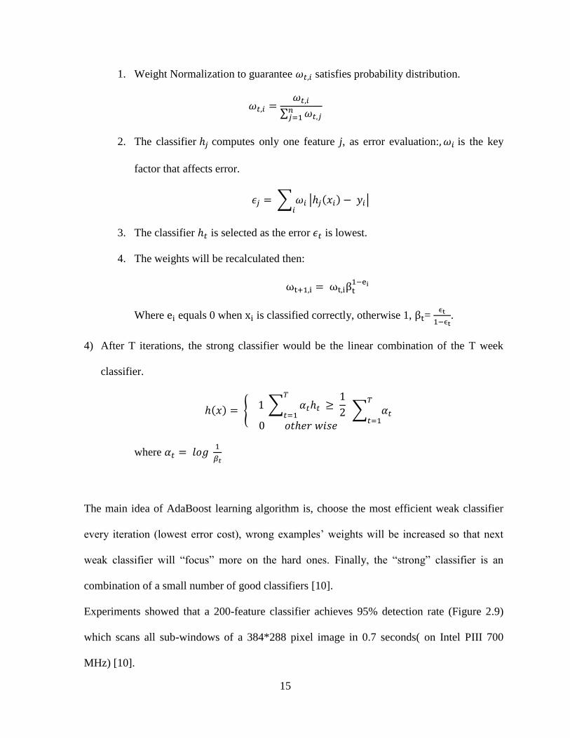
1. Weight Normalization to guarantee satisfies probability distribution.
∑
2. The classifier computes only one feature j, as error evaluation: is the key
factor that affects error.
∑
| ( ) |
3. The classifier is selected as the error is lowest.
4. The weights will be recalculated then:
Where equals 0 when is classified correctly, otherwise 1, =
.
4) After T iterations, the strong classifier would be the linear combination of the T week
classifier.
( ) { ∑
∑
where
The main idea of AdaBoost learning algorithm is, choose the most efficient weak classifier
every iteration (lowest error cost), wrong examples’ weights will be increased so that next
weak classifier will “focus” more on the hard ones. Finally, the “strong” classifier is an
combination of a small number of good classifiers [10].
Experiments showed that a 200-feature classifier achieves 95% detection rate (Figure 2.9)
which scans all sub-windows of a 384*288 pixel image in 0.7 seconds( on Intel PIII 700
MHz) [10].

16
Figure 11.9: 200-feature classifier curve of receiver operating characteristic (ROC) [4].
Figure 2.10 shows how the Adaboost works in reality. First feature is the region of the eyes
and upper cheeks, usually eye region is darker than upper cheeks. Second region is the
difference between eye region and bridge of nose [4].

17
Figure 12.10: Relevant good features in Adaboost [4].
2.4 Real-Time solution
2.4.1 The Attentional Cascade
In fact, only 0.01% sub-windows are the positive example (faces). To realize the real-time
face detection, computation time should be spent mostly on the potentially sub-windows. In
order to reject the negative examples, simpler classifiers are made to filter the sub-windows,
more complex classifier would only be applied to the potential instances.
A simple 2-feature classifier acts as first layer of cascade which could detect 100% positive
examples with false rate of 40% based on an experiment operated on a validation set. The
first layer classifier could extremely reduce the examples needed to be detected with
acceptable false rate. [4] On second layer, a 10-feature can handle more complex work with
the “good” examples filtered by first classifier.
The framework of cascade is a degenerate decision tree (Figure 2.11). Positive examples will
be sent to the next layer with more complex classification while negative examples detected
will be discarded.

18
Figure 13.11: Cascade consists of several classifiers. Failure examples will be discarded, only the
“potential” examples are able to reach the next layer for “harder” detection [4].
Cascade of classifiers is a wonderful method to solve the operation time wasted on the
irrelevant sub-windows in single image. Given that only a small set of sub-windows could be
used as potential face, Cascade of classifiers could bypass the negative sub-windows and try
harder on the positive ones is really efficient.
2.4.2 Cascade of Classifiers Training
As mentioned above, there are three main parameters of the cascade. The number of the
layers (strong classifiers) in cascade, number of features in each strong classifier, threshold
of each strong classifier. To get the optimized combinations of these three parameters is far
more complex, cascade has to be designed gradually.
Given P = positive example set, N = negative example set. = feature numbers for ith
classifier.

19
1. The user should customize several goals for the cascade: Maximum False Positive rate (f),
Minimum True Positive rate (d), Overall False Positive rate ( ). Set
, i=0;
2. For each layer, if current layer > , a new layer is added into cascade (i++) .
1) Train a classifier with features by given example set (P and N).
2) and for current layer could be decided by the training set.
3) To meet the need of current layer ( ), decrease threshold
for the ith classifier and increase the feature numbers ( ++). Goes back to step 1).
3. For the layer which > , the false positive example generated by current cascade
will be replacement of current Negative examples N.
2.4.3 Viola-Jones algorithm summary
Overall, Cascaded classifier contributes to fast classification as Adaboost demonstrates itself
an extremely efficient feature selector. The whole framework of Cascaded classifier is shown
as following (Figure 2.12):

20
Figure 14.12: Adaboost Face Detection Framework

21
3 Development of Face Detection Platform
3.1 Hardware Overview
To date, ARM based software development has become a hot topic in cutting-edge research
of Embedded System. There is no doubt that the choice of linux kernel, the core of the
operating system, plays a significant role in Embedded Face Detection.
3.2 OMAP
OMAP (Open Multimedia Applications Platform) is a series of image/video processors
developed by Texas Instruments, including a general-purpose ARM processor core for
portable or mobile multimedia use.
3.2.1 Gumstix Overo Board
Gumstix Overo FireSTORM COM (computer-on-module) with a 3rd
generation OMAP high-
performance applications processor is selected to be Face Detection System platform (Figure
3.1).

22
Figure 15.1:Gumstix Overo FireSTORM COM
Key components of Gumstix FireSTORM COM are as following [22]:
1) Micron 512MB DDR LPDRAM & 512MB NAND Flash Memory
Package-on-package solution minimizes power consumption and increases speed.
2) Micro SD card slot
Storage expansion for Linux operating system.
3) Texas Instruments DM3730 Applications Processor
1 GHz ARM Cortex-A8 high-performance microprocessor, including a 720p HD DSP
imaging and video accelerator and PowerVR SGX graphics accelerator with Open GL ES
2.0 and OpenVG support.
4) Texas Instruments Power Management

23
The TPS65950 device is a highly integrated power-management integrated circuit (IC)
that supports the power and peripheral requirements of the OMAP3-driven Overo series
COMs.
As mentioned above, Gumstix Overo board strives to minimize power-consumption and
maximizes board speed using highly integrated circuit design and package-on package
memory solution.
3.2.2 Gumstix Overo Expansion
Tobi board, developed by Gumstix, is the expansion for Gumstix Overo FireSTROM (Figure
3.2), which provides HDMI connector, USB OTG, USB client, USB Host, Mini USB,
10/100baseT Ethernet, 40-pin header with GPIO, PWM and A/D lines. Tobi expansion board
could be configure through an RS232 serial terminal over USB with the FTDI FT232RQ
interface. A full-featured embedded LAB controller is applied onto this board ensuring high
performance and throughput, furthermore, PanelBus package contributes to low-current, low-
noise, high-speed digital interface.
Tobi board connects Overo FireSTORM COM with 2X70 –Pin AVX Connectors.
Figure 16.2: Gumstix Tobi Expansion Board

24
As mentioned above, Gumstix Overo board strives to minimize power-consumption and
maximizes board speed using highly integrated circuit design and package-on package
memory solution.
3.3 System Requirement
3.3.1 Operating System Development
The Overo series supports Yocto Project, Ubuntu by Linaro and Angstrom software images.
Ubuntu is the most popular desktop Linux distribution which is composed of many software
packages[23]. It is safe to say Ubuntu is the best supported Linux Kernel among the three
ones. Ubuntu’s features such as APT-based package management tools, GNOME are very
attractive. In this paper Ubuntu is chosen as Operating System.
3.3.2 Ubuntu
Ubuntu by Linaro is developed by a not-for-profit engineering organization that works on
open-sourced software for the ARM architecture [29].
Though we could talk to Gumstix platform though serial console such as Minicom [30], it is
obviously too complex if the research goes on, a bootable MicroSD card with installed
operating system (Ubuntu) is needed then.
The steps of building Bootable MicroSD card are:
1) Get an image ready for installation, connect MicroSD card to development machine.
2) Determine the device filename of MicroSD card and mount partitions on the drive.
3) Calculate the size of the card and divide the card.

25
4) Create two partitions in the MicroSD card,: a FAT partition containing the boot files, a
Linux partition containing root file system.
5) Customize operating system option such as login in account .
Once the MicroSD card is ready, insert it into Overo FireSTORM COM, now we have a
linux operating system ready to use.
3.3.3 Hardware Framework
Figure 3.3 shows how the whole architecture works. The input devices (keyboard, mouse,
webcam) are connected through USB Hub with its own power supply, since USB OTG port
of the Tobi board can supply only 100mA that is not enough if a couple of devices are
attached to the hub.
The basic idea of Embedded Face Detection contains three steps:
1) Capture video through Camera, video stream is sent to storage buffer for later use.
2) Face Detection handler (process) draws frame from the video stream, preprocess the
image to meet the requirements of face detection.
3) Searching faces in the image using approach discussed in chapter 2 and localize the faces.
4) Note the detected object with rectangle or circle, display the result.

26
Figure 17.3: Hardware Design of Embedded Face Detection System
The webcam selected is Gigaware which could be fully supported by V4L2 driver library.
Figure 3.4 shows the real system.
Figure 18.4: Hardware Design of Embedded Face Detection System

27
4. Development of Facial Expression Recognition
4.1 Background
Facial expression is the most informative way in common communication. Not only in
computer vision field, method of facial expression recognition is highly discussed in
psychology, medicine science. Basically, face expression technology consists of face
movements interpretation and recognition [33]. Psychologically, face expressions are
classified into six basic types (anger, disgust, fear, happiness, sadness and surprise). In 1978,
Ekman et al. introduced [35] Facial Action Coding System (FACS), in this case, face
expression is standardized as the combination of Action Unit (AU). Table 1 shows some
instances of AU.
AU Number FACS Name Muscular Basis
0 face
1 Inner Brow Raiser Frontalis (pars medialis)
2 Outer Brow Raiser Frontalis (pars medialis)
4 Brow Lowerer Corrugator supercilii,
Depressor supercilii
5 Upper Lid Raiser Levator palpebrae
superrioris, superior tarsal
muscle
6 Cheek Raiser Orbicularis oculi (pars

28
orbitalis)
……..
Table 1: List of Action Units and Action Descriptors (with underlying facial muscles) [41].
According to AU, six universal emotions could be illustrated as following (Table 2):
Expression FAUs coded description
Anger 4+7+(((23 or 24)with or not 17) or (16+(25 or 26)) or (10+16+(25 or
26))) with or not 2
Disgust ((10with or not17) or (9 with or not 17))+(25 or 26)
Fear (1+4)+(5+7)+20+(25 or 26)
Happiness 6+12+16+(25 or 26)
Sadness 1+4+(6 or 7)+15+17+(25 or 26)
Surprise (1+2)+(5 without 7)+26
Table 2: The facial expression synthesis rules [34].
4.2 Face Expression Recognition Process
The main process to achieve face expression recognition is shown in Figure 4.1. Quite
similar to face detection, it also requires preprocessing of image and feature extraction, the
mainly difference is in classification part, which will be discussed later in this section.

29
Figure 19.1: Facial expression recognition process (Note: image face is from Cohn-Kanade
database)
The primary processes of face expression recognition are [38]:
1) Image is captured from webcam input, video files, image database.
2) The rotation, scaling, translation of face would highly affect the performance of the
whole system. Input image must be normalized before feature calculation. Segmentation,
erase noise, face location are commonly used in preprocess.
3) Shape model, patch model, texture are considered as major features of face.
4) Classifier operates the face expression categories.
5) In order to level up the performance of whole system, post process would correct the
output to reach a higher accuracy.
4.3 Face Expression Recognition Overview
In this paper Face Expression System consists of two major parts:1 Face features detection
and normalization , 2 Feature classification. The flow diagram of proposed system is shown
in Figure 4.2. Both parts could be separated to offline training section and online testing
section. Details of each part will be illustrated below.

30
Figure 20.2: Face Expression Recognition System
4.4 Face Feature Detector
The initialization procedure is performed in a half-automatic way using Active Shape Model
(ASM), which was introduced by Cootes and Taylor. The face feature detector is trained with
a set of annotated sample images. Since manually annotating a large amount of images is
tedious and error prone job, MUCT dataset is used in this research.
4.4.1 MUCT Database

31
The MUCT database consists of 3755 faces with 77 manual landmarks. Compared to other
face database [39], MUCT database provides more diversity of lighting, age, and ethnicity
(Figure 4.3).
Figure 21.3: The five cameras and their relationship to the subject’s face.
4.4.2 ASM
Based on Facial Geometry, raw image data reprocess could be classified into two categories:
1.Global (rigid) transformation, 2 local (non-rigid) deformation. The first one is less
constrained with a wider variance in image. That is to say, the size, location, rotation of face
could be unpredictable. On the contrary, second type is highly constrained, local deformation
must be learned from a training set [31].

32
4.4.3 Procrustes analysis
As mentioned above, deformation model requires highly constrained training data. In order to
remove rigid motion from raw annotated data, Procrustes analysis is put into use (Figure 4.4).
Figure 22.4: From left to right, raw data, translation, rotation, scale
Following steps show how Procrustes analysis works:
1) The first shape is set as mean shape of the whole set.
2) Align all the other face to the mean shape.(centralization, translation, rotation, scale)
3) Recalculate mean shape from the new aligned shape
4) Repeat step 2,3 until mean shape is mathematical convergent.
4.4.4 PCA
The face deformation model represents the difference of shape between objects and
expression inside of it. So as to PCA(Principal Component Analysis), a procedure that
convert correlated variables to a set of linearly uncorrelated variables [21] by orthogonal
transformation, is used to compute low-dimensional subspace which contains all the face
shape points.

33
4.4.5 Feature Point Detector
According to the approach discussed above, human face could be located in the image as a
bounding box, as it shows in chapter2. After Cascade classifier locates face bounding box,
the reference shape is applied to the image related to the bounding box. In order to fit the
reference model to face area, offset and scaling need to be taken into account, which are
based on the width of bounding box. Finally, feature nodes will be annotated on the face.
4.5 Feature Displacement
The first image in the frame sequence is considered as initial one with neural face. Face
features are extracted by face detector from the first one (Figure 4.5), displacement of face
feature nodes caused by face expression motion are key features of face expression. In order
to capture the difference of face feature nodes among frame sequence, face tracking need to
be performed.
Figure 23.5: Landmarks show face feature in the image

34
4.5.1 Face Expression Representation
The universal 6 basic human expression could be represented by face feature node
displacement. As figure 4.5 shows, when an expression is performed, displacement of feature
nodes are able to reveal the face motion. That’s to say, there is a certain way of every node’s
movement of expression. For example, nodes 6,7,8,9 represent jaw area, when coordinates of
these go down respectively, hopefully detected face is performing a surprise expression
leading to jaw drop.
Figure 24.6: Face feature nodes displacement reveal Expression motion
4.5.2 Face feature tracking
In reality, the performance of detecting face feature nodes with peak expression by face
detector discussed above is quite low since it is trained from MUCT database which mainly
consists of neural faces. Since some faces could be out of shape due to big motion of face
part, face feature nodes are hard to be detected and located correctly and accurately in peak
expression (Figure 4.7). To achieve this goal, feature nodes need to be gained sequentially

35
with small motion every frame in a robust method. In this paper, Optical Flow is a great
solution to track feature nodes by sequence.
Figure 25.7: Face detector fails to detect and locate feature nodes in peak expression. Mouth and
jaw area is messed up.
4.5.3 Optical Flow
Optical flow is the pattern of apparent motion of image objects between two consecutive
frames caused by the movement of objects [42]. Optical flow would work properly when
meets following requirements.
1. Brightness remains unchanged. The object (point) keeps same light intensity through all
the frames. This is the chief assumption of Optical Flow.
2. Small motion, displacement of one point should not vary great over time so that
derivative with respect to the spatial and temporal coordinates could be calculated.

36
3. Spatial consistency, a set of surrounding points must move in the same direction with the
same velocity ( Lucas-Kanade specified).
Given a pixel I(x,y,t) in first frame (the initial one),which moves in the next frame by
distance ( , ) in time. According to the requirement 1 mentioned above:
I(x,y,t) = I(x+ , ,t+ )
With restriction 2 to this equation , apply taylor series approximation to the right side, then
divide by dt, the equation goes to :
=0
Where:
;
;
Above equation is Optical Flow equation, whereas, could not be solved due to two unknowns.
Lucas-Kanade method is put into use to solve this equation.
In this paper, OpenCV library provides OpticalFlow procedure which returns next frame
feature points corresponding to given previous frame and points. All the face feature nodes
training and test processed are done within Cohn-Kanade (CK+) database.
4.5.4 Cohn-Kanade database (CK+)
There are 593 sequences across 123 subjects which are FACS coded at the peak frame in
CK+ database, all sequences are AAM tracked with 68points landmarks for each image. 327
sequences among the whole database have emotion labels referring the last frame (peak

37
frame). The labels range from 0-7, which represent the universal emotions. (i.e. 1=anger,
2=contempt, 3=disgust, 4=fear, 5=happy, 6=sadness, 7=surprise).
In this paper, a sequence of faces will be handled at one time, after initialization of first
frame (face feature detection on neural face), Optical Flow procedure keeps track of
following frames till the last one (peak emotion).As figure 4.8 shows, feature nodes of peak
emotion frame are much better than the one discussed in chapter 4.5.3.
Figure 26.8: Face feature tracking from left to right, up to down.
4.5.5 Face feature displacement training
Once the feature nodes of the first and last frame in sequences are captured, the displacement
of face feature will be calculated. Face expression are represented by totally 76 feature nodes.
Given node ( ) coordinate ( ), the displacement of one sample is
converted to:
{
38
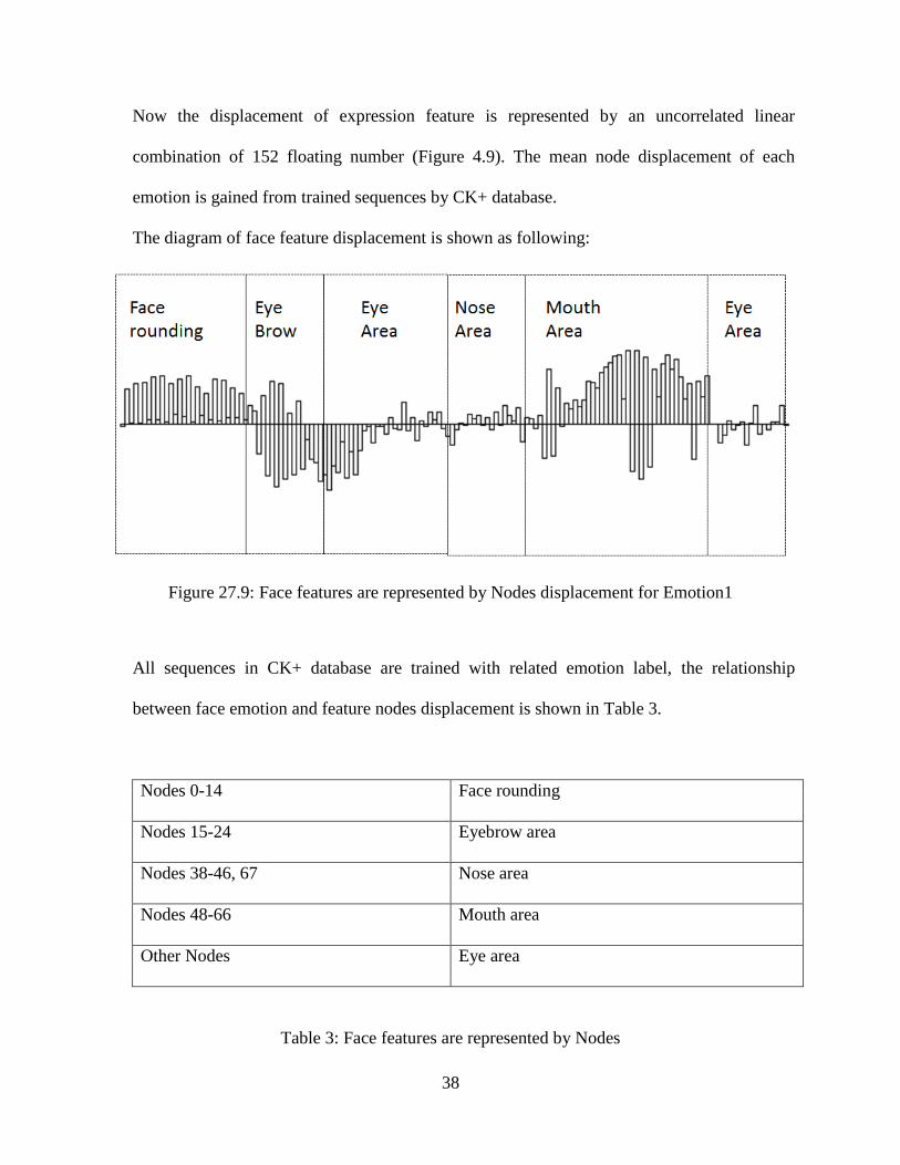
Now the displacement of expression feature is represented by an uncorrelated linear
combination of 152 floating number (Figure 4.9). The mean node displacement of each
emotion is gained from trained sequences by CK+ database.
The diagram of face feature displacement is shown as following:
Figure 27.9: Face features are represented by Nodes displacement for Emotion1
All sequences in CK+ database are trained with related emotion label, the relationship
between face emotion and feature nodes displacement is shown in Table 3.
Nodes 0-14 Face rounding
Nodes 15-24 Eyebrow area
Nodes 38-46, 67 Nose area
Nodes 48-66 Mouth area
Other Nodes Eye area
Table 3: Face features are represented by Nodes

39
The mean displacement of feature nodes of all 7 emotions are shown in Figure 4.10.
Figure 28.10: Seven Emotion Feature Nodes displacement model in same scale
Take emotion 7 (surprise) as example, jaw drop and eyebrow raise significantly when a face
is expressing surprise. As it shows above, surprise motion is obviously much bigger than the
other emotions’. While emotion 2 (contempt), displacement is comparatively small since the

40
it is more close to neural face than the others, the center part of a contempt face varies little
in reality.
4.5.6 SVM
The vector of displacement of each sequence face feature nodes is used as input to an SVM
classifier so that a model of given data is trained. SVM (support vector machines) [43] are
learning models which is able to analyze data and recognize patterns so that it could act as
classifier. SVM builds a model with given set of training example along with categories,
making its classifier capable of sorting unseen example.
Given training dataset with two categories which is linear separable, SVM model tries its
best to separate the data and maximize their distance. The gap region which separates these
two type of data is called “the margin” (Figure 4.11).
Figure 29.11: The optimal separating hyperplanes maximize the margin of the training data [44].

41
In this paper, since training data are not linear separable, the (Gaussian) radial basis function
kernel, or RBF kernel, is used in SVM classification to achieve higher accuracy.

42
5. Evaluation and Conclusion
5.1 Evaluation
The experiment was performed to evaluate the performance of Face Expression Recognition
System. Training and test data were both from CK+ database which consists of 326 samples.
Table 4 shows the overall output result corresponding to different sample rate.
Train data 100 out of 326
Emotion Trained number Test number Error Number Error rate Detection Rate
1 14 31 5 16.13% 83.87%
2 4 14 3 21.43% 78.57%
3 21 37 4 10.81% 89.19%
4 9 16 3 18.75% 81.25%
5 21 48 2 4.17% 95.83%
6 6 22 3 13.64% 86.36%
7 25 58 2 3.45% 96.55%
Total 100 226 22 9.73% 90.27%
Train data 150 out of 326
Emotion Trained number Test number Error Number Error rate Detection Rate
1 20 25 0 0.00% 100.00%
2 8 10 2 20.00% 80.00%
3 32 26 3 11.54% 88.46%
4 10 15 2 13.33% 86.67%
5 33 36 1 2.78% 97.22%
6 8 20 5 25.00% 75.00%
7 39 44 1 2.27% 97.73%
Total 150 176 14 7.95% 92.05%
Train data 200 out of 326
Emotion Trained number Test number Error Number Error rate Detection Rate
1 27 18 0 0.00% 100.00%
2 10 8 1 12.50% 87.50%
3 40 18 1 5.56% 94.44%
4 12 13 2 15.38% 84.62%

43
5 45 24 1 4.17% 95.83%
6 14 14 0 0.00% 100.00%
7 52 31 1 3.23% 96.77%
Total 200 126 6 4.76% 95.24%
Train data 250 out of 326
Emotion Trained number Test number Error Number Error rate Detection Rate
1 36 9 0 0.00% 100.00%
2 13 5 1 20.00% 80.00%
3 47 11 1 9.09% 90.91%
4 17 8 0 0.00% 100.00%
5 53 16 1 6.25% 93.75%
6 19 9 0 0.00% 100.00%
7 65 18 1 5.56% 94.44%
Total 250 76 4 5.26% 94.74%
Table 4: Performance of Face Expression Recognition System with different sample rate.
As table 4 shows, for each single emotion, the performance is getting better with the growing
number of training data except emotion2, since motion of contempt emotion is quite little and
there are two examples which are hard to be detected. The overall performance is quite
promising as it shows, totally detection rate 94.74%, especially for emotion 1,4,6, which
achieve 100% accuracy.
5.2 Conclusion
This thesis covered many aspects involved in developing an Embedded System for ARM
based development board, face detection system, face expression recognition system and
system evaluation. Face detection methods was discussed and implemented, face expression
recognition system was built based on previous work then. Due to the power of CPU and
DSP of the hardware, face detection could not be achieved real-time.

44
Face Expression Recognition runs pretty well with promising result, however, it is highly
constrained to the input data which must be standard and sequential with small motion
between frames. Face expression needs to be classified through a dynamic process (video or
camera) and brightness background must remain unchanged. Future work will focus on
filtering the influence caused by image background so that system is more widely used in
common ways.
In conclusion, Embedded Face Detection& Face Expression Recognition System is low
power consumption, portable and cost-effective system for surveillance or public use, which
is very promising with further work on robustness and flexibility.
45
Reference
[1] Jochebed Nissi.Elipe, Maya Patil, Tejaswi.S and R.P. 2012, “Implementation of
embedded face recognition system based on Linux and ARM9”, World Journal of
Science and Technology 2012, 2(10):79-82. ISSN:2231-2687
[2] E.Ardizzone, M.La Cascia, M.Morana 2012, “Face Processing on Low-Power Devices”,
Embedded and Multimedia Computing, 2009. EM-Com 2009. 4th International
Conference, pp.1-6. Dec, 2009.
[3] B.koteswar rao, P.Rama Krishna, MA.Wajeed 2013, “Real Time Embedded Face
Recognition using ARM7”, International Journal of Research in Computer and
Communication Technology, Vol 2, Issue 5, May,2013.
[4] Paul Viola, Michael J.Jones, 2004, “Robust Real-Time Face Detection,” International
Journal of Computer Vision, Col57 Issue 2, pp.137-154, 2004.
[5] Fei Wang, Jingdong Wang, Changshui Zhan, James Kwok “Face recognition using
spectral features," the The Journal of the Pattern Recognition Society, 2007
[6] Vinary Kumar B, “Race Recognition Using Gabor Wavelets," Department of Electronics
and Communication Engineering, Global Academy of Technology.
[7] Chi Ho CHAN, “Multi-scale Local Binary Pattern Histogram for Face Recognition,"
School of Electronics and Physical Sciences, University of Surrey, September, 2008.
[8] Yoav Freund and Robert E.Schapire, “A Decision-Theoretic Generalization of On-Line
Learning and an Application to Boosting," Journal of Computer and System Sciences
55,119-139, 1997.
[9] Constantine P. Papageorgiou, Michael Oren, Tomaso Poggio, Mechatronics, “A General
Framework for Object Detection,” Center for Biological and Computational Learning,
Artificial Intelligence Laboratory, MIT
[10] Kostantina Palla, Alfredo Kalaitzis, “Robust Real-time Face Detection,” School of
Informatics, University of Edinburgh, Feb, 2009.
[11] Jan Sochman, Jiri Matas, 2011, “AdaBoost Lecture,” Center for Machine Perception,
Czech Technical University, Prague.

46
[12] Padhraic Smyth, “Face Detection using the Viola-Jones Method,” Department of
Computer Science, University of California, Irvine, 2007.
[13] Javier Ruiz-del-Solar, Rodrigo Verschae, “Object detection using cascades of boosted
classifiers," Department of Electrical Engineering, Universidad de Chile, 2006.
[14] Erik Hjelmas, Book Kee Low, “Face Detection: A Survey," Computer Vision and Image
Understanding 83,236-274, 2001.
[15] Kristopher Reese, Yufeng Zheng, Adel Elmaghraby, “A Comparison of Face Detection
Algorithms in Visible and Thermal Spectrums," International Conference on Advances in
Computer Science and Application, pp.49-52, 2012.
[16] Mooseop Kin, SeungWan Han, “Real-time face detection reconfigurable device," ICT
Convergence (ICTC), International Conference, pp. 726-727. 2013.
[17] Shang-Hung Lin, “An Introduction to Face Recognition Technology," Informing
Science Special Issue on Multimedia Informing Technologies, part.2, vol.3, no.1, 2000.
[18] Kin Choong Yow, Roberto Cipolla, “Feature-Based Human Face Detection," Image
Cision Comput.15(9):713-735,1997.
[19] Paola Campadelli, Raffaella Lanzarott, Chiara Savazzi, “A feature-based face
recognition system," Image Analysis and Processing, Proceedings. 12th
International
Conference, pp.68-73, 2003.
[20] Wenyi Zhao, Rama Chellappa, “Image-based Face Recognition: Issues and Methods,"
ISBN: 9780824707835, pp.375-402, 2002.
[21] http://en.wikipedia.org/wiki/Principal_component_analysis.
[22] https://store.gumstix.com/index.php/products/267/.
[23] http://en.wikipedia.org/wiki/Ubuntu.
[24] Yongzhong Lu, Jingli Zhou, Shengsheng,”S survey of Face Detection, Extraction and
Recognitoin”, Computers and Artificial Intelligence, vol.22, pp.163-195, 2003.
[25] Henry A. Rowley, Shumeet Baluja, Takeo Kanade, “Neural Network-Based Face
Detection,” Pattern Analysis and machine Intelligence, IEEE Transactions, vol.20,
issue.1, pp.23-28, 1998.
[26] Abbas Bigdeli, Colin Sim, Morteza Biglari-Abhari, and Brian C.Lovell, ”Face Detection
on Embedded System”, ICESS 07 Proceeding of the 3rd
international conference on
Embedded Software and Systems, pp.295-308, 2007.

47
[27] Jianxin Wu, S. Charles Brubaker, Matthew D.Mullin, and James M.Rehg, “Fast
Asymmetric Learning for Cascade Face Detection,” Pattern Analysis and Machine
Intelligence, IEEE Transactions, vol.30, issue.3, pp.369-382, 2008.
[28] T.Theocharides, G.Link, N.Vijaykrishnan, M.J.Irwin, and W.Wolf, “Embedded
Hardware Face Detection,” VLSI Design, Proceeding.17th
International Conference,
pp.133-138, 2004.
[29] http://en.wikipedia.org/wiki/Linaro.
[30] http://en.wikipedia.org/wiki/Minicom.
[31] Daniel Lelis Baggio, Shervin Emami, David Millan, Escriva, and KjvedcheniaLevgen
“Mastering OpenCV with Practical Computer Vision Projects,” ISBN: 978-1-84951-782-
9, 2012.
[32] Kotsia and I.Pitas, “Real time facial expression recognition from images sequences
using Support Vector Machines,” Image Processing, 2005.ICIP 2005.IEEE international
Conference, pp.966-9, 2005.
[33] John Chia, “Emotion Recognition through Facial Expressions,” Department of
Computer Science, University of British Columba, Vancouver, BC
[34] Irene Kotsia and Ioannis Pitas, “Facial Expression Recognition in Image Sequences
Using Geometric Deformation Features and Support Vector Machines,” Image
Processing, IEEE Transactions, vol.16, issue.1, pp.172-187, 2007.
[35] Ewa Piatkowska, “Facial Expression Recognition System,” College of Computing and
Digital Media, DePaul University, 2010
[36] Philipp Michel and Rana El Kaliouby, “Facial Expression Recognition using Support
Vector Machines,” Computer Laboratory, University of Cambridge.
[37] Ting Shan, Abbas Bigdeli, Brian Lovell, Shaokang Chen, “Robust Face Recognition
Technique for a Real-Time Embedded Face Recognition System," ISBN 13:
9781599048079.
[38] Claude C. Chibelushi and Fabrice Bourel, “Facial Expression Recognition: A Brief
Tutorial Overview”.
[39] Stephen Milborrow, John Morkel, Fred Nicolls, “The MUCT Landmarked Face
Database”.
[40] Amy Ross, “Procrustes Analysis”, Department of Computer Science and Engineering,
University of South Carolina.

48
[41] http://en.wikipedia.org/wiki/Facial_Action_Coding_System.
[42] http://en.wikipedia.org/wiki/Optical_flow.
[43] http://en.wikipedia.org/wiki/Support_vector_machine.
[44] http://docs.opencv.org/modules/ml/doc/support_vector_machines.html.
[45] http://english.china.com/zh_cn/Olympic/spotlight/11068320/20080813/15025578.html.

49
Vita
Yun Zhou was born on Mar 31, 1989 in Nanjing, Jiangsu, China. He received the B.E. degree in
Electrical Engineering from Nanjing University of Aeronautics and Astronautics in 2011 and
enrolled in the Electrical Engineering graduate program at Worcester Polytechnic Institute (WPI)
in 2013. Since 2012, he has been in Embedded Research Laboratory in WPI. His research
interests focus on development of ARM-Based Face Detection systems.