Embed Size (px)
Citation preview

1
NEW TRENDS IN WELDING IN THE AERONAUTIC INDUSTRY
Patricio F. Mendez
Massachusetts Institute of Technology
Cambridge, MA 02139, USA
Abstract
Welding in the aeronautic industry is experiencing exciting developments. The widespread
application of computers and the improved knowledge and design of new materials are shaping the
way welding is implemented and process and product are being designed. There is a general trend
to reduce the use of rivets in structural components in airplanes. Diffusion welding and laser, and
electron beam welding are used to join the materials in these cases. In military airplanes electron
beam welding is continually gaining ground in the joining of titanium alloys. In large commercial
planes laser beam welds are posed to replace rivets in large parts of the fuselage. Some new
processes developed for the space industry also show promise for the aeronautic industry, among
them: friction stir welding and variable polarity plasma arc welding, which are already being used
for critical applications in rockets. A current trend of increasing the use of castings in newer
airplanes opens up new opportunities and challenges. Some processes that do not seem to have
gained widespread application include the diffusion welding of aluminum alloys and the linear
friction joining of blades for blisks. This paper focuses on the welding fundamentals, on its
implications for welding of aeronautical components, and on the trends in the industry that can be
expected from progress at a fundamental level. Repairs by welding, NDT, and brazing are left
outside the scope of this paper.
2
Introduction
Welding is a process almost as old as the processing of metals by humans. For most of its history it
has been regarded as an obscure art or a crude construction technique. New discoveries and the
availability of electric energy in the nineteenth century pushed the development of modern welding
with an ever-accelerating rate (Figure 1).
The different welding processes can be ordered by the intensity of the heat source used for fusion
(Figure 2). This ordering reveals many important trends among them. The penetration measured as
the ratio of depth to width (d/w) of the weld cross section increases dramatically with the intensity
of the heat source. This makes the welding process more efficient and allows for higher welding
speeds. A more efficient process requires less heat input for the same joint, resulting in a stronger
weld, as indicated in Figure 3. A smaller heat source moving at a faster speed also implies a much
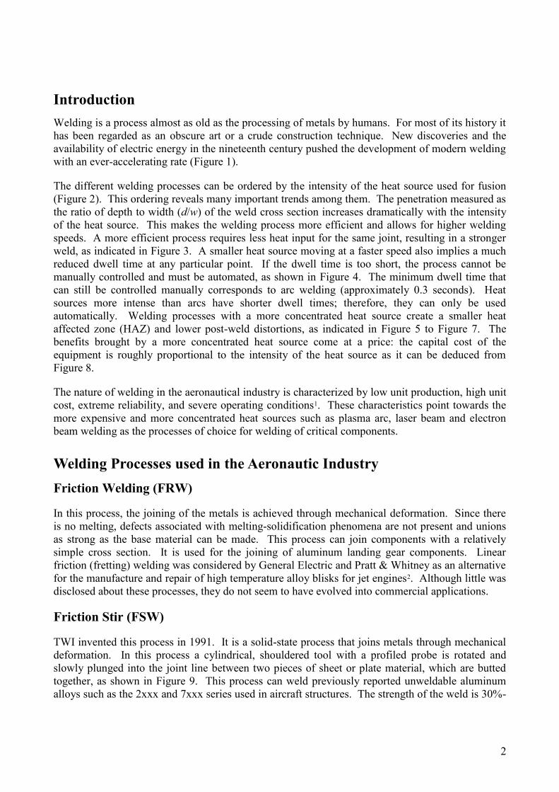
reduced dwell time at any particular point. If the dwell time is too short, the process cannot be
manually controlled and must be automated, as shown in Figure 4. The minimum dwell time that
can still be controlled manually corresponds to arc welding (approximately 0.3 seconds). Heat
sources more intense than arcs have shorter dwell times; therefore, they can only be used
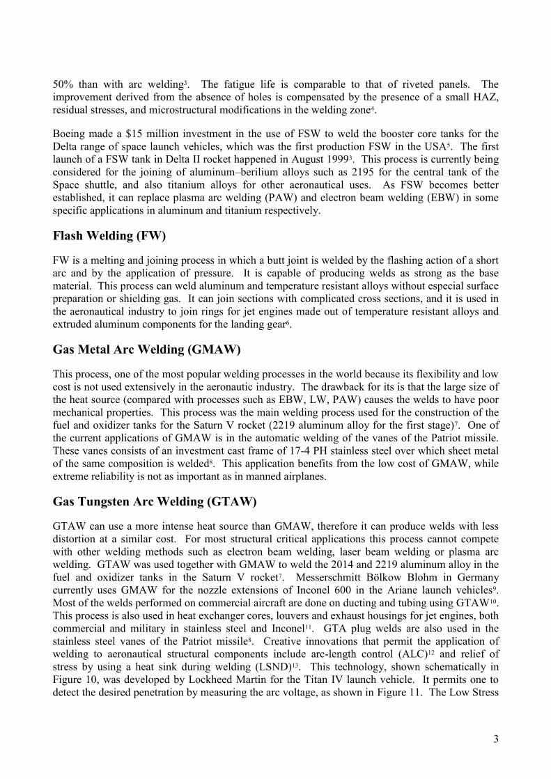
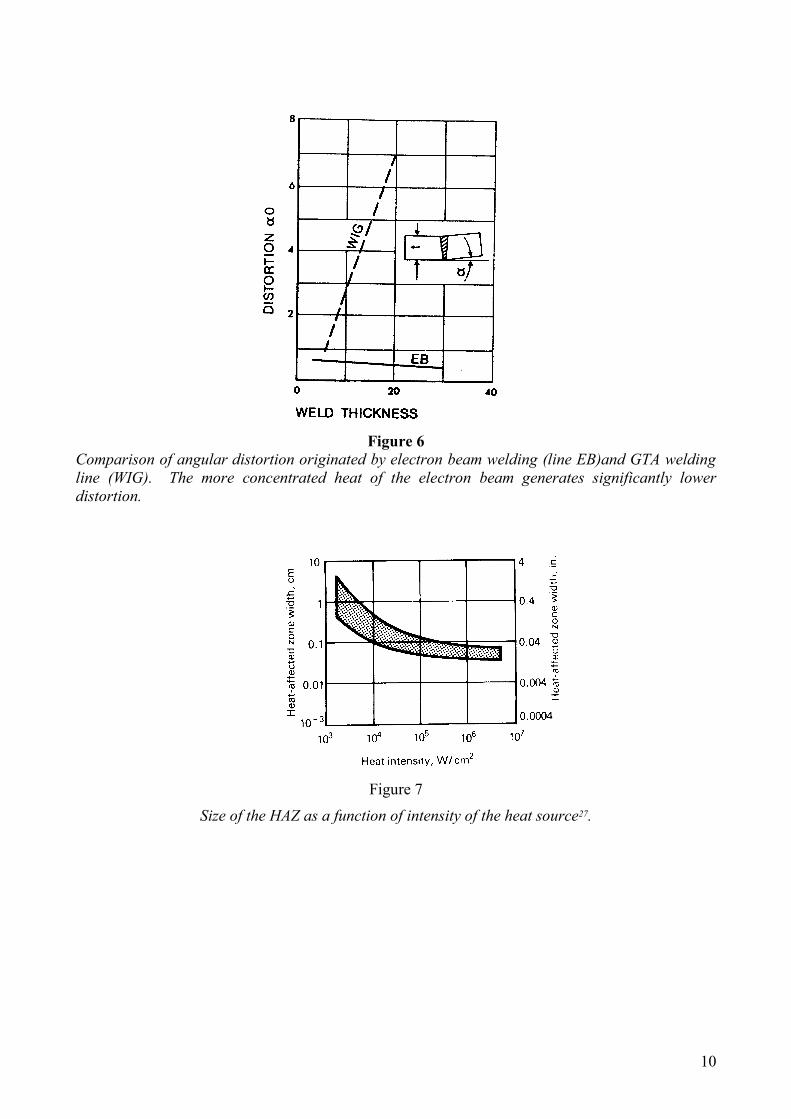
automatically. Welding processes with a more concentrated heat source create a smaller heat
affected zone (HAZ) and lower post-weld distortions, as indicated in Figure 5 to Figure 7. The
benefits brought by a more concentrated heat source come at a price: the capital cost of the
equipment is roughly proportional to the intensity of the heat source as it can be deduced from
Figure 8.
The nature of welding in the aeronautical industry is characterized by low unit production, high unit
cost, extreme reliability, and severe operating conditions1. These characteristics point towards the
more expensive and more concentrated heat sources such as plasma arc, laser beam and electron
beam welding as the processes of choice for welding of critical components.
Welding Processes used in the Aeronautic Industry
Friction Welding (FRW)
In this process, the joining of the metals is achieved through mechanical deformation. Since there
is no melting, defects associated with melting-solidification phenomena are not present and unions
as strong as the base material can be made. This process can join components with a relatively
simple cross section. It is used for the joining of aluminum landing gear components. Linear
friction (fretting) welding was considered by General Electric and Pratt & Whitney as an alternative
for the manufacture and repair of high temperature alloy blisks for jet engines2. Although little was
disclosed about these processes, they do not seem to have evolved into commercial applications.
Friction Stir (FSW)
TWI invented this process in 1991. It is a solid-state process that joins metals through mechanical
deformation. In this process a cylindrical, shouldered tool with a profiled probe is rotated and
slowly plunged into the joint line between two pieces of sheet or plate material, which are butted
together, as shown in Figure 9. This process can weld previously reported unweldable aluminum
alloys such as the 2xxx and 7xxx series used in aircraft structures. The strength of the weld is 30%-
3
50% than with arc welding3. The fatigue life is comparable to that of riveted panels. The
improvement derived from the absence of holes is compensated by the presence of a small HAZ,
residual stresses, and microstructural modifications in the welding zone4.
Boeing made a $15 million investment in the use of FSW to weld the booster core tanks for the
Delta range of space launch vehicles, which was the first production FSW in the USA5. The first
launch of a FSW tank in Delta II rocket happened in August 19993. This process is currently being
considered for the joining of aluminum–berilium alloys such as 2195 for the central tank of the
Space shuttle, and also titanium alloys for other aeronautical uses. As FSW becomes better
established, it can replace plasma arc welding (PAW) and electron beam welding (EBW) in some
specific applications in aluminum and titanium respectively.
Flash Welding (FW)
FW is a melting and joining process in which a butt joint is welded by the flashing action of a short
arc and by the application of pressure. It is capable of producing welds as strong as the base
material. This process can weld aluminum and temperature resistant alloys without especial surface
preparation or shielding gas. It can join sections with complicated cross sections, and it is used in
the aeronautical industry to join rings for jet engines made out of temperature resistant alloys and
extruded aluminum components for the landing gear6.
Gas Metal Arc Welding (GMAW)
This process, one of the most popular welding processes in the world because its flexibility and low
cost is not used extensively in the aeronautic industry. The drawback for its is that the large size of
the heat source (compared with processes such as EBW, LW, PAW) causes the welds to have poor
mechanical properties. This process was the main welding process used for the construction of the
fuel and oxidizer tanks for the Saturn V rocket (2219 aluminum alloy for the first stage)7. One of
the current applications of GMAW is in the automatic welding of the vanes of the Patriot missile.
These vanes consists of an investment cast frame of 17-4 PH stainless steel over which sheet metal
of the same composition is welded8. This application benefits from the low cost of GMAW, while
extreme reliability is not as important as in manned airplanes.
Gas Tungsten Arc Welding (GTAW)
GTAW can use a more intense heat source than GMAW, therefore it can produce welds with less
distortion at a similar cost. For most structural critical applications this process cannot compete
with other welding methods such as electron beam welding, laser beam welding or plasma arc
welding. GTAW was used together with GMAW to weld the 2014 and 2219 aluminum alloy in the
fuel and oxidizer tanks in the Saturn V rocket7. Messerschmitt Bölkow Blohm in Germany
currently uses GMAW for the nozzle extensions of Inconel 600 in the Ariane launch vehicles9.
Most of the welds performed on commercial aircraft are done on ducting and tubing using GTAW10.
This process is also used in heat exchanger cores, louvers and exhaust housings for jet engines, both
commercial and military in stainless steel and Inconel11. GTA plug welds are also used in the
stainless steel vanes of the Patriot missile8. Creative innovations that permit the application of
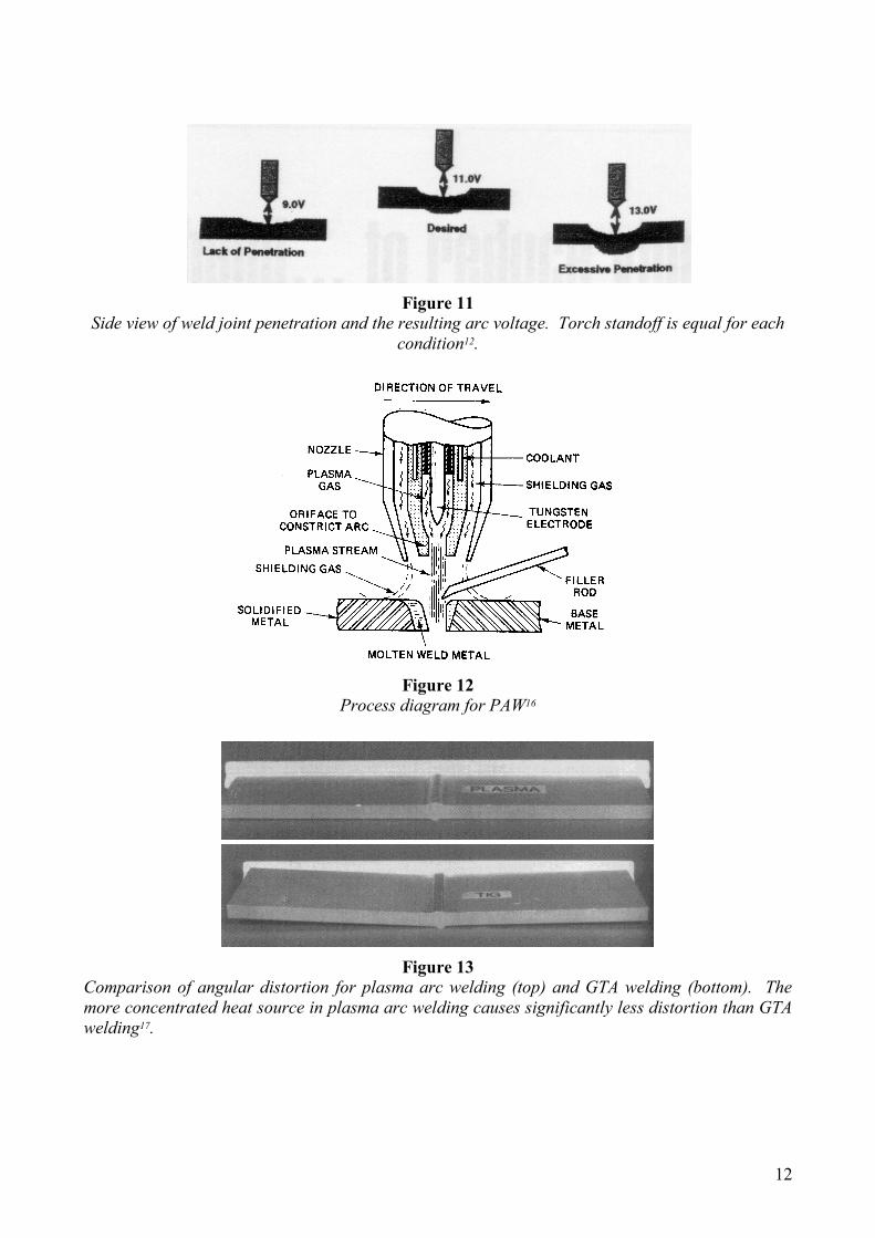
welding to aeronautical structural components include arc-length control (ALC)12 and relief of
stress by using a heat sink during welding (LSND)13. This technology, shown schematically in
Figure 10, was developed by Lockheed Martin for the Titan IV launch vehicle. It permits one to
detect the desired penetration by measuring the arc voltage, as shown in Figure 11. The Low Stress

4
No-Distortion (LSND) technique has been developed at the Beijing Aeronautical Manufacturing
Technology Research Institute in China. It has been applied to jet engine cases of heat resistant
alloys and rocket fuel tanks of aluminum alloys. In this technique, a heat sink trails behind the
welding arc in such a way that their thermal fields interact, significantly reducing the residual
stresses and distortions created by the GTAW process. Attempts to replace riveting by GTA
welding of stringers to the skin plate have not been sucessful yet due to serious distortion
problems14.
Plasma Arc Welding (PAW)
PAW uses a constricted arc between a nonconsumable electrode and the weld pool (transferred arc)
or between the electrode and the constricting nozzle (nontransferred arc). If the heat intensity of the
plasma is high enough, this process can operate in a keyhole mode, similar to that of laser or
electron beam welding, although with smaller maximum penetration. A schematic of PAW is
shown in Figure 12. This process is used for the welding of the Advanced Solid Rocket Motor
(ASRM) for the Space Shuttle15. The ASRM is made of HP-9-4-30 steel by Lockheed.
One of the latest variations of this process is variable-polarity plasma arc welding (VPPA)
commercialized by Hobart Brothers. This variation was developed by the aerospace industry for
welding thicker sections of alloy aluminum, specifically for the external fuel tank of the space
shuttle16. In this process the melting is in the keyhole mode. The negative part of the cycle
provides a cathodic cleaning of the aluminum workpiece, while the positive portion provides the
desired penetration and molten metal flow. Tests showed that the best duty cycle for this process
involves a negative current of 15-20 ms and a positive one of 2-5 ms, with a positive current 30-80
A higher than the negative current17, 18. The concentrated heat of VPPA causes significantly less
angular distortions than GTAW, as shown in Figure 13.
Laser Beam Welding (LBW)
This process, together with electron beam welding can deliver the most concentrated heat sources
for welding, with the advantages of higher accuracy and weld quality and smaller distortions. This
process is used for welding and drilling of jet engine components made of heat resistant alloys such
as Hastelloy X. Laser-processed combustors are used in the Pratt & Whitney jet engines JT9D,
PW4000, PW2037 and F-100-PW-22019
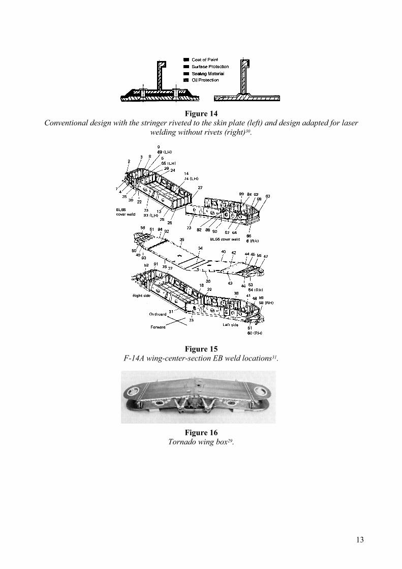
Laser beam welding will soon replace riveting in the joining of stringers to the skin plate in the
Airbus 318 and 3XX aircraft20. A schematic comparing a riveted and a welded stringer is shown in
Figure 14. Significant savings are expected to be made by replacing riveted joints by LBW.
Riveting is estimated to consume 40% of the total manufacturing man-hours of the aircraft
structure4.
Electron Beam Welding (EBW)
As mentioned above, the high intensity of the electron beam generates welds with small HAZ and
little distortion as shown in Figure 5 and Figure 6. This process presents the advantage over LBW
that it has no problems with beam reflection on the molten metal; however, it needs to operate in a
vacuum. This characteristic makes this process especially suitable for the welding of titanium
alloys that cannot be welded in an open atmosphere. Titanium alloys are widely used in military
aircraft because of its light weight, high strength, and performance at elevated temperatures. The
5
application of EBW to the welding of titanium components for military aircraft has been expanding
constantly. Pylon posts and wing components in Ti 6Al-4V for the F15 fighter have been EB
welded by McDonnell Douglas since the mid 70’s21. The wing boxes that hold the variable
geometry wings in the fighters Tornado, and F14 “Tomcat”, are also Ti 6Al-4V EB welded (Figure
15 and Figure 16). Progress in control systems and in the implementation of computers for
automation made a significant difference in the EBW of titanium alloys for military aircraft. This
new technology enables continuous one-pass welds over curved lines and surfaces, and through
varying thicknesses. Critical titanium structural components are being EB welded this way for the
Eurofighter (attachment of the wings and fin to the fuselage22) and Boeing’s F-22 (aft fuselage10).
The F-22 is the first airplane in 60 years to feature a welded fuselage. Prior fuselages were made of
riveted aluminum. The recent application of titanium castings in the F-22 presented welding
problems that delayed the start of production by at least five months23.
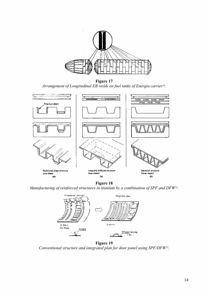
A remarkable application of EBW is in the construction of the oxygen and fuel tanks of the Russian
Energia rocket (Figure 17). Due to the large size of the tanks, the vacuum is created locally, and
sealed with ferroelectric liquids24.
Diffusion Welding (DFW)
It is a solid-state welding process that produces a weld by the application of pressure at elevated
temperature with no macroscopic deformation or relative motion of the pieces. The aeronautic
industry is the major user of DFW25. This process has proven particularly useful when combined
with the superplastic forming (SPF) of titanium alloys. In this case, complicated geometries can be
obtained in just one manufacturing step as shown in Figure 18. The quality and low cost of the
joint enables in some cases the substitution of riveted aluminum components with SPF/DFW
titanium replacements. Figure 19 shows a possible improvement for the door panel of an aircraft
fuselage. The conventional fabrication consisted of 16 parts held together by 500 fasteners. It was
proposed to replace that design by a 2-sheet assembly, integrally stiffened produced by SPF/DFW.
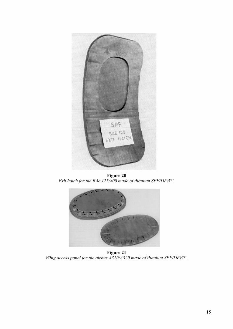
Figure 20 shows an exit hatch for the British Aerospace Bae 125/800. The application of
SPF/DFW reduces the original riveted aluminum design from 76 detail parts and 1000 fasteners to a
titanium version with only 14 details and 90 fasteners with a total cost savings of 30%. Figure 21
shows a wing access panel for the Airbus A310 and A320 in which switching from riveted
aluminum to SPF/DFW titanium achieved a weight saving in excess of 40%. The success of
SPF/DFW with titanium stimulated much research with the goal of accomplishing a similar process
with aluminum. The fundamental difference between DFW of titanium and aluminum is that
titanium can dissolve its oxides, and aluminum cannot. Therefore, the residual oxide at the
interface of an aluminum joint dramatically reduces the strength of the diffusion weld. This
problem has prevented the SPF/DFW of aluminum from being generally adopted.
Conclusions
Driven by cost and weight savings, technological progress is moving in the direction of replacing
rivets and fasteners with welds. In commercial aircraft this trend is already in motion with the
replacement of some riveted aluminum components by SPF/DFW titanium substitutes (SPF/DFW
of aluminum is still at an experimental stage). In the near future, Airbus planes (A318 and A3XX)
will feature fuselage stringers laser welded to the airplane skin. Looking further into the future, it is
likely that friction stir welding will be applied on airplane structural components, since it can
reliably join alloys of the series 2xxx and 7xxx.

6
Variable polarity plasma arc welding (VPPA), originally designed for space applications might
pervade into the airplane industry for the joining of medium thickness sections of aluminum. The
implementation of computer control to electron beam enabled the use of welding of titanium alloys
in applications that were no feasible in the past, such as manufacturing a welded fuselage for the
first time for a jet fighter (the F-22). It is reasonable to expect that the amount and criticality of
EBW of titanium in future military aircraft will increase. The use of castings in aircraft is
increasing; this will surely bring up new challenges that had not been present with wrought alloys.
References 1. Shaw, C.B. Welding Research for Aerospace in USA. in International Congress on Welding Research. 1984.
Boston, MA.
2. Irving, B., Sparks Begin to fly in Nonconventional Friction Welding and Surfacing. Welding Journal, May
1993: p. 37-40.
3. Boeing, http://www.boeing.com , 2000
4. Welded Aluminium Aircraft Structures Ready for Take Off. Welding and Metal Fabrication, September 1998:
p. 16-17.
5. The Welding Institute, http://www.twi.co.uk , September, 1999
6. Kuchuk-Yatsenko, S.I., V.T. Cherednichok, and L.A. Semenov. The Flash-Butt Welding of Aluminium Alloys.
in Welding in Space and the Construction of Space Vehicles by Welding. 1991. New Carrolton, MD: American
Welding Society.
7. Masubuchi, K., Integration of NASA-Sponsored Studies on Aluminum Welding. NASA CR-2064, 1972,
NASA, Washington, DC.
8. Irving, B., GTA Welders Put the Finishing Touches on the Fins for the Patriot Missile. Welding Journal, may
1991: p. 71-74.
9. Wolf, D.B. and R.C. Nicolay. Welded Nozzle Extension for Ariane Launch Vehicles. in Welding in Space and
the Construction of Space Vehicles by Welding. 1991. New Carrolton, MD: American Welding Society.
10. Irving, B., EB Welding Joins the Titanium Fuselage of Boeing's F-22 Fighter. Welding Journal, December
1994: p. 31-36.
11. Anderson, C.T., Robotic GTAW Keeps Jet Engine Components Flying. Welding Journal, November 1987: p.
45-46.
12. Christner, B.K., R. Lovell, and M. Campbell, Developing a GTAW Penetration Control System for the Titan IV
Program. Welding and Metal Fabrication, April 1998: p. 33-38.
13. Qiao, G., A Survey of Development in Welding Stress and Distortion controlling in Aerospace Manufacturing
Engineering in China. Welding in the World, 1999. 43(1): p. 64-74.
14. Scott, G. and S.W. Williams, TIG Welding Aluminium Stringers on Skin Structures. Welding and Metal
Fabrication, July 1999.
15. Irving, B., Plasma Arc Welding Takes on the Advanced Solid Rocket Motor. Welding Journal, December 1992:
p. 49-50.
16. Cary, H.B., Modern Welding Technology. Fourth ed. 1998, Prentice Hall.
17. Cary, H. Variable Polarity Plasma Arc, Keyhole Welding of Aluminum. in Welding in Space and the
Construction of Space Vehicles by Welding. 1991. New Carrolton, MD: American Welding Society.
18. VanCleave, B.P. and W.R. Gain. Keyhole Plasma Arc Welding of Aluminum. in Welding Technology for the
Aerospace Industry. 1980. Las Vegas, NV: American Welding Society.
19. High-Power Lasers Solve Jet Engine Manufacturer's Welding and Drilling Problems. Welding Journal,
February 1993: p. 54-55.
20. Radaj, D., et al. Modelling of Laser Beam Welding with Complex Joint Geometry and Inhomogeneous
Material. in 5th International Seminar Numerical Analysis of Weldability. 1999. Graz-Seggau, Austria:
International Institute of Welding.
21. Pogorzelski, F.S. Novel Approaches to Electron Beam Welding Machine Utilization. in Welding Technology
for the Aerospace Industry. 1980. Las Vegas, NV: American Welding Society.
22. Farmer, I., P. Dawson, and R. Fletcher, Green Light for Eurofighter. Welding and Metal Fabrication,
January/February 1999: p. 8-11.
23. Capaccio, T., http://www.seattletimes.com/news/business/html198/altlock_021298.html , Production of F-22
jets faces delay, 1998

7
24. Kazakov, V.A. and O.K. Nazarenko. State-Of-Art and Prospects of development of Electron Beam Welding of
Aerospace Vehicles. in Welding in Space and the Construction of Space Vehicles by Welding. 1991. New
Carrolton, MD: American Welding Society.
25. Dunkerton, S.B. and C.J. Dawes. The Application of Diffusion Bonding and Laser Welding in the Fabrication
of Aerospace Structures. in Advanced Joining of Aerospace Metallic Materials. 1985. Oberammergau,
Germany: Advisory Group for Aerospace Research & Development (NATO).
26. David, S.A. and T. DebRoy, Current Issues and Problems in Welding Science. Science, July 1992. 257: p.
497-502.
27. Eagar, T.W., Energy Sources Used for Fusion Welding, in ASM Handbook. 1993, ASM International. p. 3-6.
28. Robinson, I.B. Aluminum and Its Alloys: Weldability. in Welding Technology for the Aerospace Industry.
1980. Las Vegas, NV: American Welding Society.
29. Berggreen, J. Economical Manufacturing and Inspection of the Electron-Beam-Welded "Tornado Wing Box".
in Advanced Joining of Aerospace Metallic Materials. 1985. Oberammergau, Germany: Advisory Group for
Aerospace Research & Development (NATO).
30. Schubert, E., M. Klassen, and G. Sepold, High Power Laser Applications for the Transport Industry. Welding
in the World, 1999. 43(Supplementary Issue): p. 154-162.
31. Messler, R.W. and C.A. Paez. Welding for Low-Cost Advanced Titanium Airframe Structures. in Welding
Technology for the Aerospace Industry. 1980. Las Vegas, NV: American Welding Society.
32. Williamson, J.R. Diffusion Bonding in Superplastic Forming/Diffusion Bonding. in Welding Technology for
the Aerospace Industry. 1980. Las Vegas, NV: American Welding Society.
33. Stephen, D. and S.J. Swadling. Diffusion Bonding in the Manufacture of Aircraft Structure. in Advanced
Joining of Aerospace Metallic Materials. 1985. Oberammergau, Germany: Advisory Group for Aerospace
Research & Development (NATO).
Figures
Figure 1
Growth of welding processes since electrical energy became readily available26

8
Figure 2
Welding processes ordered according to heat source intensity27.
Figure 3
There is a general correlation between the effective heat input and the resulting weld strength28
102 104 105 106 107103
Air
/fu
el g
as
flam
e
Ele
ctr
osl
ag, o
xy
acety
len
e
flam
e, t
herm
ite
Fri
cti
on
Arc
weld
ing
Resi
stan
ce w
eld
ing
Ox
yg
en
cu
ttin
g
Pla
sma A
rc W
eld
ing
Ele
ctr
on
beam
Lase
r b
eam
W/m2
practical range for welding
d/w
efficiency
HAZ size
interaction
max speed
cost
-
%
cm
s
cm/s
$
.2
1
1-10
10-100
0.1
103
10
99
.01-.1
10-4 - 10-3
1000
106
0.1-1
104
9
Figure 4
Maximum weld travel velocity, heat source spot, and interaction time as a function intensity of the
heat source27.
Figure 5
Cross sections of welds performed with electron beam (left) and GTA (right). The higher heat
intensity of the electron beam creates a much smaller fusion zone and HAZ29.
human response time
automatic processesmanual processes
10
Figure 6
Comparison of angular distortion originated by electron beam welding (line EB)and GTA welding
line (WIG). The more concentrated heat of the electron beam generates significantly lower
distortion.
Figure 7
Size of the HAZ as a function of intensity of the heat source27.

11
Figure 8
Capital cost of welding equipment as a function of productivity27.
Figure 9
Friction stir welding process5
Figure 10
Side view of a proximity sensor attached to a welding torch to measure torch standoff12.
12
Figure 11
Side view of weld joint penetration and the resulting arc voltage. Torch standoff is equal for each
condition12.
Figure 12
Process diagram for PAW16
Figure 13
Comparison of angular distortion for plasma arc welding (top) and GTA welding (bottom). The
more concentrated heat source in plasma arc welding causes significantly less distortion than GTA
welding17.
13
Figure 14
Conventional design with the stringer riveted to the skin plate (left) and design adapted for laser
welding without rivets (right)30.
Figure 15
F-14A wing-center-section EB weld locations31.
Figure 16
Tornado wing box29.
14
Figure 17
Arrangement of Longitudinal EB welds on fuel tanks of Energia carrier24.
Figure 18
Manufacturing of reinforced structures in titanium by a combination of SPF and DFW32.
Figure 19
Conventional structure and integrated plan for door panel using SPF/DFW25.
15
Figure 20
Exit hatch for the BAe 125/800 made of titanium SPF/DFW33.
Figure 21
Wing access panel for the airbus A310/A320 made of titanium SPF/DFW33.