Embed Size (px)
Citation preview
ABSTRACT SUBMISSION
Title: Design Analysis of the Ares I Pogo Accumulator
Authors:Luke A. Swanson, ERC, ESTS GroupThomas V. Giel, ERC, ESTS Group
An Ares I Upper Stage (US) pogo stability analysis [1,2] has shown that a Liquid Oxygen(LO2) feed line pogo suppressor will be necessary to mitigate the threat of pogo couplinginstability. A variety of different pogo instability suppression systems have been used onseveral heritage launch vehicles and many include a relatively simple gas chargedaccumulator. An accumulator functions by absorbing energy from the feed line fluidcolumn oscillations to prevent pogo instability, and reintroduces that energy around anew frequency associated with the accumulator design. The governing parameters of theaccumulator depend on its location, which ideally is one to two feed line diametersupstream of the pump inducer. A proper accumulator Compliance shifts the vibrationfrequency of the feed line liquid column between the tank and the accumulator (the ‘longcolumn’) out of the range of vehicle pogo instability frequencies. The accumulator onlyshifts the sensed frequency of the ‘long column’, and does not adequately absorb energyfrom the fluid column oscillation in the duct between the accumulator and the pump (the‘short column’). Therefore, the short column oscillations must be damped withappropriate accumulator communication port resistance to prevent unstable pogocoupling. Also, the accumulator must react rapidly to column oscillations to suppresspogo instabilities, and the accumulator response is controlled by limiting the accumulatorinertance.
An annular gas filled accumulator suppressor was selected for the Ares I US LO2 feedline, and the requirements levied on the US pogo accumulator led to the selection of fivepotential accumulator gas charging concepts. Design concepts include a single-timecharge bottle, a level control vent system, and liquid level sensing. Additionalcomponents, such as a heater or mixing chamber, were considered to provide the desiredcharge gas conditions into the accumulator. Each potential concept is presented alongwith the trade study evaluation and selection of the final charge system design. Theability to meet and maintain the accumulator compliance and inertance requirements forsuccessful pogo suppression is considered for each concept. Analyses used to evaluatethe concepts as part of this trade study are detailed. The helium required by each of theseconcepts is also considered and compared to the usable helium provided by differenthelium sources in the US Main Propulsion System (MPS), in order to determine ifadditional helium needs to be carried to meet the suppression system requirements, anddefine the most appropriate helium source for the accumulator. Safe venting of oxygenwas also considered for design concepts as appropriate.
The primary requirements levied on the pogo suppression system are compliance,resistance, and inertance for the selected accumulator location. The required complianceis met by providing and maintaining an associated gas volume in the accumulator, while
https://ntrs.nasa.gov/search.jsp?R=20090034946 2018-06-26T01:05:13+00:00Z

averting helium ingestion into the engine. The resistance requirement is met by thedesign of the feed line interface ports, allowing the feed line and accumulator tocommunicate. Damping requires establishing an LO2 flow resistance (a pressure drop vs.fluid flow) for the suppressor inlet holes, also called suppressor communication ports.The resistance must dampen short column oscillations yet not prevent the suppressorfrom absorbing flow oscillation energy from the “long column” mode, requiring aspecified range of resistance. The accumulator also must react in an appropriate time topogo induced fluid oscillations requiring a small maximum accumulator inertance(pressure change to accelerate the accumulator fluid flow) so it reacts to the pogopressure pulse. This inertance must be considered in selection of the accumulatorgeometry, liquid volume, and feed line interface design to ensure adequate pogosuppression is provided. In order to properly suppress pogo, the system must be designedto function under the range of conditions expected for the LO2 feed line. Therefore, thepotential pressure and temperature variations in the LO2 feed line, caused by thepropellant tank pressurization system and vehicle acceleration, were accounted for.
Helium consumption requirements were also considered in the concept selection process.The helium needed from the vehicle during flight is a significant impact of thesuppression system, potentially requiring added storage capability. Therefore, usable andrequired helium calculations were considered to weigh the impacts of each concept.
A passive level control concept was selected as the best design to provide helium to thepogo accumulator. The system uses a level control vent array in the accumulator tomaintain the accumulator gas volume and LO2 level, which meet required complianceand inertance goals, respectively. The results presented indicate that this conceptminimizes potential risks, such as the failure to provide the required gas volume andengine helium ingestion. In addition the selected concept provides the best means tocharge the pogo suppression system with helium by minimizing complexity and failuremodes. This concept is presented in additional detail, considering the components andconfiguration necessary to minimize weight and complexity while providing the neededfault tolerance to provide a reliable design. The current configuration is depicted inFigure 1 and includes a model of the LO2 feed line and pogo accumulator. The annularaccumulator is located between the feed line ball strut tie rod assembly and gimbal andcommunicates with the feed line through two rows of holes, sized to provide theappropriate resistance. The bleed valves provide a path for thermal conditioning beforeoperation. Suppression is provided after helium enters the accumulator through theredundant charge valves. The overboard drain line is included to maintain the liquidlevel, preventing the gas from overflowing into the feed line. The liquid level ismaintained to provide the appropriate inertance for the accumulator and the appropriategas volume to establish the needed accumulator compliance. A small section of the drainline extends into the accumulator using a dip tube configuration, providing a designsimilar to the Space Shuttle Main Engine pogo accumulator overflow pipe. The passivelevel control design thus met the inertance, resistance, and compliance requirements forall potential operating conditions. Furthermore, the helium required to providesuppression can be met with the on board helium supply.

Check MValve
L02 Pre-ValveOrificeOverboard fDrain
Drain L02 Feedline Pogo
Valve Accumulator
rEngine Interface
Figure 1 - Baseline Pogo Suppression Design
REFERENCES
1. Doiron, Hal and Arndt, Scott; Ares I US PDR Pogo Stability Analyses, Briefing toNASA MSFC, June 10, 2008
2. ARES I GUIDANCE, NAVIGATION, AND CONTROL (GN&C) SYSTEMDEFINITION DOCUMENT (SDD) VOLUME V: LIFTOFF, SEPARATION, ANDPOGO ANALYSIS, CxP 72069-05, DRAFT June 25, 2008

Design Analysis of the Ares I POGO Accumulator
Luke A. Swanson1 and Thomas V. Giel2 ERC, Inc., ESTS Group, NASA Marshall Space Flight Center, Huntsville, AL, 35812
Several accumulator designs and gas charge systems are considered in order to suppress POGO within the Ares I vehicle Upper Stage Liquid Oxygen System. The thermodynamic and flow analysis completed to evaluate candidate designs are presented and the results are used to evaluate the ability of each concept to meet the levied suppression requirements. One annular accumulator design meets all suppression requirements while also providing manufacturability and operability advantages. Of the two proposed charge systems to provide and maintain gas within the accumulator, a passive level control design meets the charge requirements and maximizes reliability.
Nomenclature AP = Communication port area A(s) = Liquid flow path cross-sectional area at s CA = Compliance DP = Communication port diameter gc = Conversion between mass and force gs = Gravitational acceleration at sea level I = Inertance Pg = Absolute pressure of the charge gas volume RL = Resistance of the accumulator communication ports m& = Mass flow rate Vol = Volume s = Accumulator liquid flow path tW = Feed line wall thickness ΔP = Liquid oxygen pressure loss through accumulator communication ports γg = Ratio of specific heats of the charge gas ρL = Liquid Oxygen density
I. Introduction iquid propellant rockets can experience an unstable coupling between the primary axial vibrational mode of the vehicle structure and some other vehicle subsystem capable of exciting this structural mode1. Involvement of
the primary axial mode led to this coupling being commonly referred to as ‘POGO’. Historically, POGO is most often the result of the following feedback loop: vehicle axial vibration -> propellant feed system pressure oscillation -> engine thrust variation -> vehicle axial vibration. A work by von Pragenau provides an excellent overview of this most common POGO mechanism2.
L
Several means of POGO suppression have been employed on heritage vehicles, but the most common method introduces fluid compliance, often in the form of a gas bubble, close-coupled to the engine turbopump inlet. Such a gas bubble absorbs, or ‘accumulates’, pressure oscillations and is thus commonly referred to as an accumulator and is analogous to a spring-mass vibration damper. In contrast to provision of fluid compliance via a gas-filled accumulator, the Titan II fuel system provided compliance via a piston-spring mechanism. In the Gemini program, the Titan II rocket used a vertical standpipe filled with nitrogen as its accumulator; which attached to the feed line close to the oxidizer pump inlet3. Several methods of separating the accumulator gas from the propellant to preclude its ingestion by the engine system have been implemented, such as containment of the gas by a bladder or a metal bellows, each used on particular Titan III vehicles3. In the absence of such a physical barrier between accumulator
American Institute of Aeronautics and Astronautics
1
1 Engineer, Main Propulsion Systems Branch, AIAA Member. 2 Senior Engineer, Main Propulsion Systems Branch, AIAA Senior Member.

gas and liquid propellant, one must control the location of the resulting gas-liquid interface, to avoid either gas ingestion into the engine turbopump or loss of compliance due to reduction in accumulator gas volume, and likely also provide active/continuous gas charging of the accumulator to enable such control.
The POGO suppression accumulator for the Space Shuttle is located between the low- and high-pressure oxygen turbopumps 4. The accumulator is pre-charged with helium, but gaseous oxygen (GO2) is provided from an engine heat exchanger shortly after engine start. Overflow ports allow the GO2 flow to exit the accumulator, thus maintaining the Liquid Oxygen (LO2) level in the accumulator just low enough to uncover these ports. Overflow GO2 returns to the feed system upstream of the low-pressure turbopump where it condenses back to LO2.
A POGO suppression system was implemented for the center engine of the second (S-II) stage of the Saturn V vehicle for the later Apollo missions5. The accumulator consisted of an annular cavity around the liquid oxygen feed line. A charge system was required to fill the accumulator with helium within 5-7 seconds of charge flow initiation which occurred soon after engine start6. The helium charge flow continued throughout engine burn. After filling the accumulator, the gas overflowed into the feed line and was ingested by the engine.
American Institute of Aeronautics and Astronautics
2
The Ares I Upper Stage Engine (USE) burns liquid hydrogen (LH2) and LO2 propellants. Figure 1 depicts the major elements of the US, including the propellant tanks, which are separated by a common bulkhead. Feed lines convey the propellants to the USE turbopumps. The LO2 feed line is relatively short due to the aft location of the LO2 tank. Yet, preliminary Ares I POGO stability analyses 7,8 reveal the likely need for POGO suppression both shortly after USE start and during the last roughly 1/3rd of USE operation. Thus, the LO2 feed system likely requires POGO suppression throughout USE operation. Though more refined analyses and test data have yet to confirm the absolute need for POGO suppression, design efforts must proceed to ensure design/cost/schedule targets will ultimately be met.
As with past LO2-LH2 propelled stages, the main POGO concern lay with the LO2 feed system. A similar feedback loop may exist in the LH2 feed system, but gains for this loop are low for a variety of reasons including: low LH2 density; relatively high LH2 compressibility, or self compliance; and small LH2 contribution to total thrust chamber mass flow rate (high oxidizer to fuel flow ratio). The J-2X engine vacuum thrust (Fv) sensitivities to LO2 pressure (Po) variations, oV PF ∂∂ , are predicted9 to be 7.4 times greater than the sensitivities to LH2 pressure (Pf) variations fV PF ∂∂ .
A relatively simple gas-filled accumulator-based suppressor design was selected for the Ares I US LO2 feed system in recognition of the historical dominance of this general type of design. An accumulator functions by absorbing energy from the feed line fluid column oscillations to prevent POGO instability, and reintroduces that energy around a new frequency associated with the accumulator design. A proper accumulator design shifts the vibration frequency of the feed line liquid column between the tank and the accumulator that is sensed at the pump inducer, out of the range of vehicle POGO frequencies. The governing parameters of the accumulator depend on its location, which is ideally 1 to 2 feed line diameters upstream of the pump inducer, because an accumulator only shifts the sensed frequency of the fluid column segment above the accumulator (the ‘long column’ between the tank and the accumulator as indicated in Fig. 2), and does not adequately absorb energy from the fluid column oscillation in the duct between the accumulator and the pump (the ‘short column’ mode). Since the Ares I accumulator location is more than two line diameters from the pump inducer cavitation compliance, the short column oscillations must also be damped to prevent unstable POGO coupling. Damping requires establishing an LO2 flow resistance (a pressure drop vs. fluid flow) for the suppressor to feed line holes, called the suppressor communication ports. The resistance must damp the short column oscillations but must not prevent the suppressor from absorbing flow oscillation energy from the “long column” mode, requiring a limited range of resistance. The accumulator also must react quickly to POGO induced fluid oscillations requiring a small maximum
LH2 Tank
LO2 Tank
Common Bulkhead
Figure 1. Ares I Upper Stage.
accumulator inertance (pressure change to accelerate the accumulator fluid flow) so it reacts to the early stages of POGO pressure pulses.
II. Procedure A variety of gas filled accumulator designs were considered along with several different systems for charging
and maintaining the gas volume. The following analysis was implemented to evaluate these concepts and select the best design for providing the required compliance, inertance, and resistance.
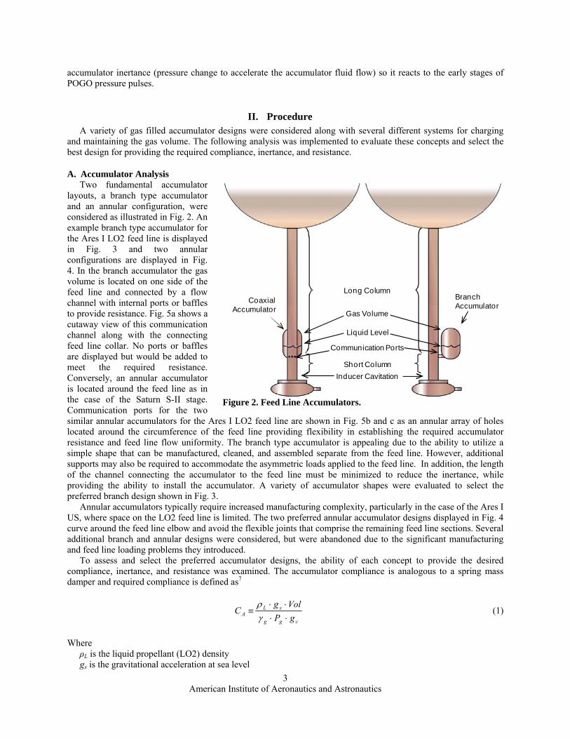
A. Accumulator Analysis Two fundamental accumulator
layouts, a branch type accumulator and an annular configuration, were considered as illustrated in Fig. 2. An example branch type accumulator for the Ares I LO2 feed line is displayed in Fig. 3 and two annular configurations are displayed in Fig. 4. In the branch accumulator the gas volume is located on one side of the feed line and connected by a flow channel with internal ports or baffles to provide resistance. Fig. 5a shows a cutaway view of this communication channel along with the connecting feed line collar. No ports or baffles are displayed but would be added to meet the required resistance. Conversely, an annular accumulator is located around the feed line as in the case of the Saturn S-II stage. Communication ports for the two similar annular accumulators for the Ares I LO2 feed line are shown in Fig. 5b and c as an annular array of holes located around the circumference of the feed line providing flexibility in establishing the required accumulator resistance and feed line flow uniformity. The branch type accumulator is appealing due to the ability to utilize a simple shape that can be manufactured, cleaned, and assembled separate from the feed line. However, additional supports may also be required to accommodate the asymmetric loads applied to the feed line. In addition, the length of the channel connecting the accumulator to the feed line must be minimized to reduce the inertance, while providing the ability to install the accumulator. A variety of accumulator shapes were evaluated to select the preferred branch design shown in Fig. 3.
Annular accumulators typically require increased manufacturing complexity, particularly in the case of the Ares I US, where space on the LO2 feed line is limited. The two preferred annular accumulator designs displayed in Fig. 4 curve around the feed line elbow and avoid the flexible joints that comprise the remaining feed line sections. Several additional branch and annular designs were considered, but were abandoned due to the significant manufacturing and feed line loading problems they introduced.
Long Column
Short Column
CoaxialAccumulator
BranchAccumulator
Gas Volume
Liquid Level
Communication Ports
Inducer Cavitation
Figure 2. Feed Line Accumulators.
To assess and select the preferred accumulator designs, the ability of each concept to provide the desired compliance, inertance, and resistance was examined. The accumulator compliance is analogous to a spring mass damper and required compliance is defined as7
cgg
sLA gP
VolgC
⋅⋅⋅⋅
≡γρ
(1)
Where ρL is the liquid propellant (LO2) density gs is the gravitational acceleration at sea level
American Institute of Aeronautics and Astronautics
3

Vol is the helium charge gas volume γg is the charge gas ratio of specific heats Pg is the absolute pressure of the charge gas volume gc is the conversion between mass and force
Equation (1) provides the traditional POGO units of (length)2 for CA, but employing gs, commonly used to define acceleration g’s (≡ acceleration/gs) erroneously implies CA changes linearly with vehicle acceleration. Dropping gs/gc from Eq. (1) results in the same CA value but units of mass/pressure.
The resistance of the suppressor communication ports is defined as ( )scL gmgPR ⋅⋅Δ= & (2) where:
∆P is the pressure loss of the LO2 as it flows through the communication ports m& is the mass flow rate Equation (2) provides the traditional POGO units of (time)2/(length)2 for RL but again employing gs erroneously
implies RL changes linearly with vehicle acceleration. Dropping the gc/gs from Eq. (2) results in the same value but with units of pressure/(mass⋅time). Note that RL is linear with 1/ , unlike the more commonly used “head loss” resistance which is inversely proportional to 2.
m&m&
)
The inertance of the suppressor communication ports and liquid flow path in the suppressor is defined as
( ) ( )(∫ ⋅+⋅+=
sAgdsAgDtI
sPsPw /)( (3)
where:
tw is the feed line wall thickness DP is the communication port diameter AP is the communication port area s is the accumulator liquid flow path A(s) is the liquid flow path cross-sectional area at s Equation (3) provides the traditional POGO units of (time)2/(length)2 for I but again employing gs erroneously
implies I changes with vehicle acceleration. Replacing the gs with gc in Eq. (3) results in the same value, but in units of pressure/(mass/(time)2) and is appropriately interpreted as pressure drop needed to accelerate the liquid mass flow.
American Institute of Aeronautics and Astronautics
4
B. Charge System Design The POGO charge system
provides gas to the accumulator in order to meet the required CA and I. The gas bubble must be maintained in the accumulator for the duration that POGO suppression is desired, even under feed line pressure variations caused by the ullage pressure control system and vehicle acceleration. The LO2 tank ullage pressure is controlled within a band by the LO2 pressurization system, which results in pressure variations in the LO2 feed line and thus in the POGO accumulator.
The charge system must also work in conjunction with the US thermal conditioning system, in
Branch Accumulator
Feed Line Flexible Joints
Figure 3. LO2 Feed Line and Branch Accumulator.

order to chill the accumulator so that the accumulator LO2 level can be maintained. The thermal conditioning system circulates LO2 through the accumulator, from the communication ports to an accumulator high point bleed, from prelaunch until shortly before USE start. Therefore, each of the systems discussed include a high point bleed port that routes LO2 to an interface with the US recirculation system and into the LO2 tank.
After a down select from several charge system configurations, two concepts were reviewed in detail. The single time charge concept fills the accumulator gas volume after USE start and terminates gas flow just before POGO suppression is required. The design provides no active maintenance of the accumulator gas bubble. Therefore, the volume of gas sent into the accumulator must be sufficiently controlled to meet the required CA and I without overflowing gas into the feed line. Any helium that is allowed to overflow into the feed line during engine operation will be ingested by the turbopump, which can interfere with pump performance and structural integrity. A basic schematic of the single time charge concept is displayed in Fig. 6, where a dedicated charge bottle is used to send a set volume of gas into the accumulator when the charge valve is commanded open. Therefore, the gas charge bottle is sized so that the pressurized gas will expand into the accumulator and displace the liquid to the required volume range. The helium charge line interfaces with the high-point bleed used for accumulator chilldown in order to minimize penetrations into the accumulator.
The second of the down selected charge concepts is the passive level control design, which is based on the overflow pipe in the Space Shuttle Main Engine (SSME) accumulator system. In this concept, a continuous flow of gas is maintained through the accumulator, utilizing inflow and outflow ports. The charge gas enters the accumulator through the high point bleed, as with the single time charge. Initially, the gas will displace liquid in the accumulator, moving the gas/liquid interface down. Once the gas bubble expands and uncovers the level control port orifice (Fig. 7), gas will flow out this vent port, and with proper orifice sizing, downward movement of the liquid interface will end. For the branch accumulator, this level control concept can include a multi-holed pipe penetrating into the center of the accumulator, as in the SSME design. A similar result is achieved with the two coaxial accumulator concepts using a multi-holed elbow penetrating the accumulator side. This concept establishes a near constant liquid level. When the feed line pressure increases, the gas bubble is compressed and the fluid level rises above the vent port blocking helium outflow until the desired bubble volume is reestablished. If the feed line pressure decreases and the gas bubble expands, the level control port area exposed to gas increases and allows more gas outflow than inflow until the gas bubble shrinks to the desired size. This dictates that both helium and oxygen will flow out of the outflow ports under nominal conditions. The concept does not require a dedicated bottle but can be used with any helium supply already available on the vehicle with sufficient helium for continuous flow.
a) Shaped Accumulator b) Compressed Accumulator Figure 4. Annular Accumulators.
American Institute of Aeronautics and Astronautics
5

Feed Line Collar
Communication Channel
Communication Ports
a) Branch
b) Shaped Accumulator c) Compressed Accumulator Figure 5. Accumulator/Feed Line Communication.
1. Single Time Charge Analysis The single time charge concept was premised on carrying a separate bottle containing helium to be vented into the accumulator after the US engine start transient. The bottle is to be loaded with the mass of helium required to provide the specified accumulator compliance after attaining thermal equilibrium with the accumulator LO2. The initial bottle conditions (pressure and temperature) affect the initial charge gas conditions (temperature and density) and therefore the initial gas volume and compliance before thermal equilibrium is attained. Start and end point mass and isentropic energy balances provided evaluation of the required helium mass at selected pressures to provide the required gas volume at thermal equilibrium, as well as the volume and compliance attained before thermal equilibrium is reached.
Assuming the accumulator charge supply bottle reaches thermal equilibrium with a given environmental temperature before liftoff allows supply bottle gas properties and volume to be defined over a narrow range. The supply bottle volume, X, can be predicted from mass conservation before and after the bottle discharges to the accumulator from a mass balance. ( ) ife XXVol 112 ρρρ ⋅=⋅+⋅ (4) where subscripts 1i and 1f refer to the supply bottle initial and final conditions and 2e refers to the accumulator at thermal equilibrium.
American Institute of Aeronautics and Astronautics
6

When the accumulator initially charges, the supply helium expands nearly isentropically with a gas temperature defined by the enthalpy expelled from the supply bottle less the work used to push the LO2 out of the accumulator into the feed line. Equation (5) defines the enthalpy h1ex expelled from the supply bottle.
ex
ffii
fi
ffiiex m
umummm
umumh
1
1111
11
11111
⋅−⋅=
−
⋅−⋅= (5)
where m is the mass in the supply bottle, m1ex is the mass expelled and u is the helium internal energy.
The energy equation for the accumulator, including Q, heat transfer to the helium, and W, the constant pressure work to move the LO2, is:
( ) ( )
( ) ( ) ( )dtdPVol
dtdVolPhm
dtdVolP
dtdhm
dtd
umdtdWQ
dthmd
inininin
ininexex
−−⋅=⋅−⋅
=⋅=−+⋅
2222
2211
(6)
The accumulator is at a near constant pressure as it charges, so the accumulator energy equation ignoring heat transfer becomes:
( ) ( )
dtdVolPhm
dtd
dtdVolP
dthmd
ininexex −⋅=−
⋅22
11 (7)
Therefore, since the mass expelled from the charge bottle equals the mass entering the accumulator, the enthalpy
expelled must be the enthalpy entering the accumulator, h1ex = h2in. Knowing the initial accumulator enthalpy and pressure allows the initial accumulator properties to be defined and the initial accumulator volume, before the helium attains thermal equilibrium with the LO2, to be determined. Therefore the range of accumulator volume from initial charge to final thermal equilibrium can be determined, and the proper mass of helium charge predicted, to
give a satisfactory range of accumulator compliance based on heat transfer between the LO2 and helium as well as allowable charge bottle pressure and temperature variations. Accumulator insulation must be included to control heat transfer, so that bottle loading and accumulator compliance and inertance can be controlled until USE cutoff. One advantage of the annular accumulator design is the added control of accumulator heating, since LO2 is continuously flowing through the center of the accumulator volume. Also note that oxygen vaporization at the gas/liquid interface was not accounted for in the analysis of the single time charge design. GO2 generation will increase the gas volume in the accumulator, requiring a decrease in the supply bottle volume predicted from Eq. 4 in order to prevent overfilling the accumulator with gas.
Figure 6. Single Time Charge Concept Schematic.
2. Passive Level Control Analysis The helium flow into the accumulator
was determined with compressible flow equations for a choked orifice with an assumed discharge coefficient. The
American Institute of Aeronautics and Astronautics
7

maximum pressure and temperature variations expected from the helium supply system were then used to determine a range of flow rates into the accumulator.
The time for the helium to reach the level control port, after which the gas volume is fully established, is referred to as the charge time. The greatest helium supply and expected feed line pressure and temperature variations were used to determine a range of charge times by dividing the accumulator gas volume by the volumetric flow rate. However, this charge time calculation does not account for any oxygen vaporization at the helium interface and will therefore over predict the accumulator charge time. GO2 formation is also particularly important in order to correctly size the accumulator outflow ports. If the outflow ports do not allow all of the helium inflow and vaporized oxygen to exit the accumulator, the gas bubble can expand beyond the outflow ports and potentially reach the LO2 feed line.
Dalton’s law of partial pressures was used to calculate the oxygen vaporization rate. Since heat transfer from the helium will not significantly change the LO2 temperature, the saturation pressure of oxygen at the maximum expected LO2 temperatures were used as the limiting GO2 partial pressures in the accumulator. Along with the known range of possible accumulator total pressures, the range of GO2 partial pressures enabled the calculation of the minimum and maximum oxygen to helium mole ratio and the associated properties of the helium/oxygen gas mixture. A more accurate charge time was determined by accounting for this oxygen vaporization rate.
The accumulator outflow ports were sized to enable all of the helium entering the accumulator plus all of the GO2 generated in the accumulator to exit the vent, assuming a choked orifice with an assumed discharge coefficient. In addition, substantial margin was added to provide a conservative design. Margin on the outflow ports enables more flow to exit the accumulator than predicted as necessary, which allows some LO2 to regularly flow out the ports in addition to the vented gas. However, if the outflow port sizes are underpredicted and no margin is provided, gas would overflow into the feed line and interfere with engine operation. To calculate the nominal LO2 outflow, all of the outflow area that was added as margin was assumed to flow LO2. The LO2 flow rate was calculated assuming a cavitating venturi flow, since the fluid is vented to vacuum. Results were produced for a range of outflow margins. The initial estimates presented here will be refined through several test programs, which will provide the opportunity to reduce the margin and the amount of excess LO2 venting.
Figure 7. Passive Level Control Concept Schematic.
III. Results Results are presented for multiple accumulator designs, illustrating the selection process leading to the final
design and its advantages. Results of analysis to compare the two charge system concepts are also presented, indicating the differences of the two designs with respect to providing the required inertance and compliance.
A. Accumulator Analysis The compliance for the accumulators displayed in Fig. 3 and Fig. 4 are plotted as a function of liquid level in
Fig. 8. The x-axis displays the liquid height as a percent of the minimum desired liquid level, which was selected to ensure that gas will not overflow into the feed line considering the maximum anticipated slosh magnitude. Also, 0% marks the plane at the top of the feed line communication ports. The y-axis displays the compliance, which is displayed as a percent of the required CA. As the liquid height increases, the gas volume and thus the compliance
American Institute of Aeronautics and Astronautics
8

decrease. The curves show that at a minimum 100% liquid level, the compliance is approximately 137%, 215%, and 107% of the required value for the branch accumulator, shaped annular accumulator, and compressed annular accumulator respectively. Although the shaped accumulator provides significantly more margin, all three concepts meet the compliance requirement.
The compressed annular concept provides the least margin of the three accumulators, which is a significant factor when considering level variations possible with charge system variations. In addition, the time for gas to fill the compressed annular accumulator is less than required for the other two concepts at the same flow rate, increasing the risk of gas overflow into the feed line during the engine start transient, particularly if suppression is needed early.
The inertance estimates for three different accumulator designs are displayed in Fig. 9 as a function of liquid level. The inertance is displayed as a percent of the desired value, so I should remain at or below 100%. Again the liquid level height is a percent of the minimum level required to assure gas overflow will not occur. Results from the Fig. 3 branch type accumulator and the two different Fig. 4 annular designs are included and illustrates a significant disadvantage of the branch design. The inertance of the branch design is significantly greater for all displayed liquid levels because of the relatively narrow and long communication channel that is required to connect the accumulator to the feed line (Fig. 5a).
The results also explain the shape selected for the larger shaped annular concept displayed in Fig. 4a. Although both annular concepts meet the required compliance and inertance, the shaped design adds significant margin. At the bottom of the accumulator the annular region near the communication holes is narrow in both annular concepts to use liquid viscosity slosh damping10 in order to minimize accumulator slosh induced by feed line flow interaction with the communication holes. Unlike the compressed annular concept, the shaped design gets wider above the communication holes in order to decrease the inertance and increase the compliance at a given liquid height. This design also improves clearances inside the accumulator, which was a significant advantage for manufacturing, cleaning, and installing the passive level control vent tube arrangement, and provides lower stress levels imparted to the feed line.
0%
50%
100%
150%
200%
250%
300%
0% 20% 40% 60% 80% 100% 120% 140% 160% 180% 200% 220%
Liquid Height (% of Minimum)
Branch AccumulatorShaped AccumulatorCompressed AccumulatorSingle Time Charge Span
Figure 8. Accumulator Compliance versus Liquid Level.
Com
plia
nce
(% o
f Req
uire
d)
American Institute of Aeronautics and Astronautics
9

B. Single Time Charge Concept The compliance and inertance range that was predicted using the single time charge concept is also displayed in
Fig. 8 and Fig. 9. The results displayed apply to the shaped annular accumulator concept, which provides the most margin to meeting the required inertance and compliance of the three accumulator concepts presented. The dotted lines overlaid on Fig. 8 and Fig. 9 indicate a compliance and inertance range due to the possible ranges of pressure and temperature conditions of the helium in the supply bottle and in the accumulator. These results assume that the helium comes to thermal equilibrium with the LO2 in the accumulator. The two figures indicate that the minimum required liquid level cannot be achieved while simultaneously meeting the required compliance and inertance. The maximum liquid level of approximately 165% was selected in order to meet the required maximum inertance (100%). This liquid level also meets the minimum compliance required with approximately 60% margin. Because of the potential variation in initial bottle conditions and accumulator conditions, the minimum liquid level predicted is only 59% of the desired minimum, significantly increasing the risk of helium overflow into the feed line.
The single time charge results displayed in Fig. 8 and Fig. 9 assume that the helium entering the accumulator is at thermal equilibrium with the LO2. If this assumption is not valid and the helium remains at a greater temperature than the LO2 for a significant duration, the helium will overflow into the feed line. Using Eq. (7) to determine the initial gas temperature when the helium first enters the accumulator, the gas volume is much larger than when it is at equilibrium and increases the maximum compliance to 516% of the required value. The associated volume is larger than provided by the accumulator and the liquid level is reduced below 0%, forcing the gas to enter the feed line through the communication ports. In addition, because oxygen vaporization at the gas/liquid interface was not accounted for in the single time charge analysis, the compliance and inertance spans predicted are expected to increase with variations in GO2 generation in the accumulator.
40%
70%
100%
130%
160%
190%
220%
0% 20% 40% 60% 80% 100% 120% 140% 160% 180% 200% 220%
Liquid Height (% of Minimum)
Branch AccumulatorShapped AccumulatorCompressed AccumulatorSingle Time Charge Span
Figure 9. Accumulator Inertance versus Liquid Level.
Iner
tanc
e (%
of G
oal)
C. Passive Level Control Concept The predicted helium, GO2, and LO2 flow rates through the accumulator overboard drain line are displayed in
Fig. 10 as a function of charge time. Four curves are displayed for each fluid, which represent two different accumulator pressures and temperatures in order to bound the range of expected conditions. Because of the large density range between gas and liquid, the LO2 flows were plotted on the right y-axis, while the helium and GO2
American Institute of Aeronautics and Astronautics
10

0.250
0.375
0.500
0.625
0.750
0.875
1.000
0.0125
0.0175
0.0225
0.0275
0.0325
0.0375
0.0425
45% 50% 55% 60% 65% 70% 75% 80% 85% 90% 95% 100% 105%
Charge Time (% maximum)
LO2GO2He44 psia50 psia-294 F-297 F
Figure 10. Accumulator Drain Flow.
Vent
ed L
iqui
d Fl
ow R
ate
Rat
io (%
of T
otal
)
Vent
ed G
as F
low
Rat
e R
atio
(% o
f Tot
al)
flow were plotted on the primary y-axis in order to clearly show the liquid and gas results on a single plot. The flow rates are normalized by the total drain flow in order to illustrate the relative drain flow of each fluid. The charge time is displayed on the x-axis and is normalized by the maximum predicted value. Fig. 10 shows that the minimum predicted charge time is approximately 48% of the maximum because of the assumed worst case variations of the helium source and LO2 feed line conditions.
The helium flow rate is set based on the minimum charge time desired. The range of accumulator conditions then sets the maximum charge time. The four helium curves are identical but offset on the x-axis, since the mass flow calculation assumes a choked supply orifice and is not affected by the accumulator conditions. The GO2 curves match the helium trends, since Dalton’s law results in a linear relation. The LO2 flow is therefore a function of additional outflow area added for margin, to ensure that all of the gas in the accumulator is vented and not allowed to overflow into the feed line. The figure also shows that the potential accumulator pressure range introduces greater mass flow variations than the potential accumulator temperature range.
IV. Conclusion The analysis and rationale presented was used to select a baseline accumulator design in order to move forward
with the design of the Ares I vehicle. Three leading gas filled accumulator concepts were presented, including a branch type accumulator and two annular designs, which were selected from a variety of concepts initially considered. The analysis presented indicates the advantage of the shaped annular concept, which meets the desired inertance and compliance while providing the most margin to feed line gas ingestion. Alternately, the branch accumulator does not meet the required inertance because of the relatively narrow channel required to connect the accumulator to the LO2 feed line. Although the compressed accumulator was shown to provide the required compliance and inertance, margins were significantly reduced compared to the shaped accumulator and internal clearance is also a considerable problem. In addition, lower imparted feed line stress levels with the shaped accumulator further enforced this selection.
American Institute of Aeronautics and Astronautics
11
The two leading charge system configurations were presented with corresponding analysis to determine the ability of each concept to meet the compliance and inertance required to suppress potential Ares I POGO. Although both designs show promise, the passive level control was selected as the more robust design that will maintain the desired accumulator compliance and inertance for POGO suppression under all potential variations of conditions. The

American Institute of Aeronautics and Astronautics
12
margins this design provides also allow for adaptation to changes in inertance and compliance requirements relatively easily.
These preliminary analyses will be followed with more detailed transient flow models, which will be verified through several POGO test programs. These transient models will lead to improved charging and draining flow rate estimations and will predict the design’s ability to maintain the gas volume and successfully suppress POGO oscillations. The design analysis presented enables the selection of a baseline design and, even though many unknowns must be refined, grants confidence that POGO mitigation can be provided for the Ares I US.
Acknowledgments The authors acknowledge the contributions to this analysis effort of the POGO design team. In particular, the
technical guidance and analysis review provided by James “Skip” Urquhart (Jacobs Engineering) was indispensable. The helpful transient charging and heat transfer analyses provided by Alok Majumdar (NASA) augmented the analysis presented here. Bill Monk (Teledyne Brown Engineering) configured the many ideas for accumulator designs into the final three dimensional accumulator model used to generate the numerical integrations of inertance and fluid volumes at different liquid heights. In addition, Collin Jackson (Boeing) developed the spread sheet ranking tool that allowed the charging concepts to be ranked by the entire POGO team based on attributes and attribute features, including the performance attribute and features defined by the analysis reported here.
References 1 Kana, D. D., “Longitudinal Oscillations of Flight Vehicles,” Part III of The Dynamic Behavior of Liquids in
Moving Containers, Ed. H.N. Abramson, NASA Pub. SP-106, 1966 2 von Pragenau, G. L., “Stability Analysis of Apollo-Saturn V Propulsion and Structure Feedback Loop,” AIAA
Guidance, Control, and Flight Mechanics Conference, No. 69-877, Princeton, New Jersey, August 18-20, 1969 3Norquiest, L. W. S., Marucs, J. P., and Ruscio, D. A., “Development of Close-Coupled Accumulators for
Suppressing Missile Longitudinal Oscillations (POGO),” AIAA 5th Propulsion Joint Specialist Conference, No. 69-547, U.S. Air Force Academy, Colorado, June 9-16, 1969
4SSME Engineering, “Design Verification Specification Space Shuttle Main Engine POGO Suppression System”, Rockwell International, DVS-SSME-106, Revision B, February 8, 1978
5Worlund, A. L., Hill, R. D., Murphy, G. L., “Saturn V Longitudinal Oscillation (POGO) Solution,” AIAA 5th Propulsion Joint Specialist Conference, No. 69-548, U.S. Air Force Academy, Colorado, June 9-13, 1969
6Saturn Flight Evaluation Working Group, “Saturn V Launch Vehicle Flight Evaluation Report-AS-509 Apollo 14 Mission,” NASA-TM-X-69536, April 1, 1971
7Doiron, H., and Arndt, S., “Ares I US PDR POGO Stability Analyses,” Briefing to NASA MSFC, June 10, 2008
8”Ares I Guidance, Navigation, and Control (GN&C) System Definition Document (SDD) Volume V: Liftoff, Separation, and Pogo Analysis,” CxP 72069-05, DRAFT June 25, 2008
9Guidos, M., “J2X Influence Coefficients Study,” NASA MSFC ER21 Memorandum for Distribution, June 20, 2007
10”Slosh Suppression”, NASA Space Vehicle Design Criteria, NASA SP-8031, May 1969