Embed Size (px)
Citation preview

EEL 4924 ELECTRICAL ENGINEERING DESIGN (SENIOR DESIGN)
FINAL REPORT
19 APRIL 2011
SMART PRESENTATION REMOTE
TEAM MEMBERS
Margaret GARVAN Samuel SMITH
PROJECT ABSTRACT
The Smart Presentation Remote will be a remote control to enable those giving presentations using software packages such
as Microsoft PowerPoint or OpenOffice.org Impress a novel method to control their presentations and have access to extra
information while presenting in a handheld hardware package. The remote will feature the ability to advance back and
forth through slides in a similar manner to commercially-available remotes allowing the presenter to easily set the pace of
their presentation. It will also have an integrated MEMS gyroscope that will be used to control the mouse cursor, allowing
the presenter to interact with the presentation without moving to a computer. The most important feature that will
differentiate our product with other solutions is an LCD screen on the remote that gives the presenter information
pertaining to time management, slide number, and additional notes pertaining to the current slide not visible to the
audience.
The Smart Presentation Remote will be implemented with an Atmel AVR XMEGA microcontroller. This microcontroller will
interface with an LCD screen, Bluetooth module, and gryoscope. The host computer will run software to communicate with
the device over Bluetooth. The initial target host platform was Microsoft Windows 7 running Microsoft Office PowerPoint
2007/2010. Compatibility with OpenOffice.org Impress was also implemented. The device and host implement
communications over a Bluetooth serial COM port to allow compatibility with a wide range of devices and ease of
development for any future work.
UNIVERSITY OF FLORIDA ECE
EEL 4924C SPRING 2011
PAGE 2/22
FINAL REPORT: SMART PRESENTATION REMOTE
CONTENTS
Project Abstract ........................................................................................................................................................................... 1
Introduction ................................................................................................................................................................................. 3
Technical Objectives .................................................................................................................................................................... 3
Flowcharts and Diagrams............................................................................................................................................................. 5
Software....................................................................................................................................................................................... 7
Division of Labor ........................................................................................................................................................................ 10
Gantt Chart ................................................................................................................................................................................ 10
Cost Objectives .......................................................................................................................................................................... 11
References ................................................................................................................................................................................. 11
Materials and Resources............................................................................................................................................................ 11
Appendix A: Command and file Structure ................................................................................................................................. 12
Appendix B:PCB Schematics and Layouts .................................................................................................................................. 16
Figure 1 Project Block Diagram .................................................................................................................................................... 5
Figure 2 Internal Layout of Remote ............................................................................................................................................. 6
Figure 3 Microcontroller Application Flowchart .......................................................................................................................... 8
Figure 4 Visual Studio Class Diagram ........................................................................................................................................... 9
Table 1 Division of Labor ............................................................................................................................................................ 10
Table 2 Gantt Chart .................................................................................................................................................................... 10

UNIVERSITY OF FLORIDA ECE
EEL 4924C SPRING 2011
PAGE 3/22
FINAL REPORT: SMART PRESENTATION REMOTE
INTRODUCTION
Presentations made with Microsoft PowerPoint and similar programs have become an important part of modern life for
virtually all cases in which information needs to be effectively conveyed to an audience, whether in a conference room or in
a classroom. In all cases, the presenter must control the flow of the presentation in some way. In most cases this is done by
standing in front of a computer and using a mouse and keyboard at a fixed console. In many cases, a presenter can give a
more exciting and immersive presentation if he or she has freedom of motion during the presentation. The Smart
Presentation Remote will enable this and provide a better experience for both the presenter and the audience.
A number of commercial presentation remote solutions already exist. A trip to any electronics store will reveal that simple
remotes that only allow the presenter to advance and reverse slides can be had ranging in price from $50 to $100. While
these remotes are easy to use and meet the needs of many people, power users continue to demand products with more
features. There are presentation remote applications that run on smartphones like Android and iPhone. These applications
add integration with the presentation software and enable features impossible with simple remotes such as being able to
view the notes page for each slide. These applications, however, require an expensive smartphone to run on and rapidly
deplete the phone’s battery. As a solution, we offer the Smart Presentation Remote, a discrete presentation remote that
provides advanced features and integrates with popular presentation software.
TECHNICAL OBJECTIVES
The Smart Presentation Remote is the fusion of a hardware remote with a host computer server. Listed succinctly our
technical objectives fall under the categories of hardware specifications and host computer software. We also provide a
comparison of our product with existing commercial solutions.
REMOTE HARDWARE SPECIFICATIONS AND POWER CONSUMPTION
Our product integrates a number of electronic components into a compact form factor. One feature of the remote will be
the ability to control the mouse on the computer. This was accomplished using a triple-axis gyroscope which provides a
digital-16 bit output signal via a 2-wire (I²C) interface. In standard operating mode, the gyroscope consumes approximately
6.5 mA and runs at 3.3 V. We used a Rayson BTM-182 Bluetooth module to interface with the host computer over a virtual
COM port interface. Bluetooth was chosen as it is both relatively simple to implement and compatible with a wide range of
computer systems. The Bluetooth module runs at 3.3 V and consumes 58 mA of current during transmission at peak power,
while consuming far less during other operations. A distinguishing feature of our product is that it has an on-remote display.
The LCD display on the remote is an ST7565 graphic LCD with 128x64 resolution. The ST7565 LCD module consumes 120 mA
at 3.3 V. Our microcontroller is the Atmel AVR Xmega (ATxmega192A3). This chip was chosen because it has a large
number of USARTs and consumes a minimal amount of power. It can also be easily programmed using a free GNU-based
toolchain. The Xmega consumes 18.4 mA at a nominal supply voltage of 3.0 V. Finally, have a laser pointer on our handheld
unit. This is separated from the rest of the electronics and will have a simple analog circuit controlling it. The laser diode is
rated at 5 mW and runs at 3.3V. To supply power to the device, we installed a 900 mAh lithium ion battery and MAX1555
recharging IC to charge the device over a USB port.
UNIVERSITY OF FLORIDA ECE
EEL 4924C SPRING 2011
PAGE 4/22
FINAL REPORT: SMART PRESENTATION REMOTE
HOST COMPUTER SOFTWARE
The host computer software is an application to receive data from the remote and convert this data into keystrokes and
mouse movements to control the presentation. Additionally, it will process information from user-provided text files and
send it to the remote. Communications will take place over a virtual COM port implemented by the Windows Bluetooth
stack. Using this framework allowed us to rapidly interface our host computer with the microcontroller utilizing techniques
similar to those covered in our microprocessors applications course.
While our device is only compatible with the Windows operating system and PowerPoint-like software, we designed and
documented the communications protocol in such a manner that our product will be easily adaptable to a wide range of
operating systems and software packages. Theoretically, our serial protocol is completely platform agnostic and can be
implemented on any platform implementing a Bluetooth stack.
COMMERCIAL ALTERNATIVES
A number of commercial alternatives currently exist to the Smart Presentation Remote. A number of manufacturers make
simple 2.4 GHz remotes that simulate key presses to advance slides, blank the screen, and perform a number of other very
basic functions in PowerPoint. While gyroscopic computer mice have existed for over ten years, the interface was made
popular by the Nintendo Wii game console controller. A number of guides exist on the Internet for using a Wii controller
with a vibrating structure MEMS gyroscope add-on (Wii MotionPlus) as a gyroscopic mouse that can be used to control
PowerPoint. There are applications for both iOS (iPhone) and Android mobile computing platforms that allow presenters to
view some parts of the presentations on their mobile phones with extra metadata such as slide notes and timing while
giving a presentation. Our research has not uncovered any discrete device that enables this functionality. This
differentiates our product from all commercially available solutions.

UNIVERSITY OF FLORIDA ECE
EEL 4924C SPRING 2011
PAGE 5/22
FINAL REPORT: SMART PRESENTATION REMOTE
FLOWCHARTS AND DIAGRAMS
Figure 1 Project Block Diagram
UNIVERSITY OF FLORIDA ECE
EEL 4924C SPRING 2011
PAGE 6/22
FINAL REPORT: SMART PRESENTATION REMOTE
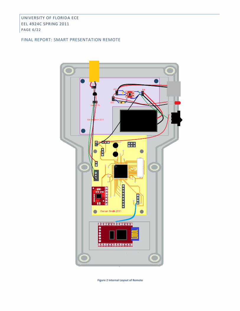
Figure 2 Internal Layout of Remote

UNIVERSITY OF FLORIDA ECE
EEL 4924C SPRING 2011
PAGE 7/22
FINAL REPORT: SMART PRESENTATION REMOTE
SOFTWARE
OVERVIEW
The Smart Presentation Remote requires software to run on both the Atmel Xmega microcontroller as well as the host PC.
Interfacing between the applications is done through Bluetooth. The microcontroller communicates through a Bluetooth
UART device and the host PC connects to the device and treats it as a virtual COM port. Throughout the semester, we have
written a functional remote control application that demonstrates the capabilities of our device, but the framework was not
easily extensible.
MICROCONTROLLER PROGRAM
Our microcontroller program is relatively simple. It starts by initializing all the peripherals and drivers. It also draws the
Gator Engineering logo to the screen on startup to demonstrate the features of the graphical LCD. The body of the program
runs in a continuous loop in which it polls the gyroscope over I²C. It also checks the keypad. Debouncing the keypad is
performed by only transferring the keypad value during an interrupt routine which will be described later.
Interrupts are used to control the rest of the microcontroller program. The real-time clock is configured to generate
interrupts at a rate of 8 Hz to transmit the keypad and gyroscope data to the host computer using the Xmega USART. The
device implements a set of control words to manipulate device functionality from the host computer software. The final
version of the software implements control bytes for the following features:
1. Clear screen buffer
2. Move screen buffer pointer to next line
3. Render and draw text to screen
4. Laser pointer toggle
The current implementation is based on using the Bluetooth TX interrupt and transferring each read character (except
control characters) to a small text buffer. When the render command is issued, the text is drawn to the screen. Rendering
the LCD contents is performed through the driver provided for the screen.
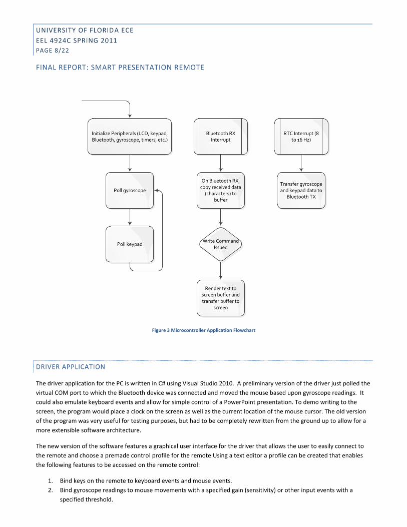
A flowchart for the primary functionality of the driver program is provided below:
UNIVERSITY OF FLORIDA ECE
EEL 4924C SPRING 2011
PAGE 8/22
FINAL REPORT: SMART PRESENTATION REMOTE
Initialize Peripherals (LCD, keypad, Bluetooth, gyroscope, timers, etc.)
Bluetooth RX Interrupt
RTC Interrupt (8 to 16 Hz)
On Bluetooth RX, copy received data
(characters) to buffer
Transfer gyroscope and keypad data to
Bluetooth TXPoll gyroscope
Poll keypadWrite Command
Issued
Render text to screen buffer and transfer buffer to
screen
Figure 3 Microcontroller Application Flowchart
DRIVER APPLICATION
The driver application for the PC is written in C# using Visual Studio 2010. A preliminary version of the driver just polled the
virtual COM port to which the Bluetooth device was connected and moved the mouse based upon gyroscope readings. It
could also emulate keyboard events and allow for simple control of a PowerPoint presentation. To demo writing to the
screen, the program would place a clock on the screen as well as the current location of the mouse cursor. The old version
of the program was very useful for testing purposes, but had to be completely rewritten from the ground up to allow for a
more extensible software architecture.
The new version of the software features a graphical user interface for the driver that allows the user to easily connect to
the remote and choose a premade control profile for the remote Using a text editor a profile can be created that enables
the following features to be accessed on the remote control:
1. Bind keys on the remote to keyboard events and mouse events.
2. Bind gyroscope readings to mouse movements with a specified gain (sensitivity) or other input events with a
specified threshold.

UNIVERSITY OF FLORIDA ECE
EEL 4924C SPRING 2011
PAGE 9/22
FINAL REPORT: SMART PRESENTATION REMOTE
3. Enable the timer feature. This can either be a simple clock or a stopwatch with start, stop, and reset buttons.
4. Enable the notes feature. Notes are selected from a menu in the GUI.
5. Enable the “buzzword” feature. A file containing buzzwords is selected in the GUI.
Figure 4 Visual Studio Class Diagram

UNIVERSITY OF FLORIDA ECE
EEL 4924C SPRING 2011
PAGE 10/22
FINAL REPORT: SMART PRESENTATION REMOTE
DIVISION OF LABOR
Table 1 Division of Labor
Margaret Garvan Samuel Smith
Preliminary Research 50 50
Purchasing Components 50 50
Documentation 50 50
Initial Component Testing 50 50
Microcontroller Programming 50 50
Driver Programming 20 80
Board Design 60 40
Housing Design 80 20
Manual Assembly 60 40
Testing and Debugging 50 50
Final Presentation 50 50
GANTT CHART
Table 2 Gantt Chart

UNIVERSITY OF FLORIDA ECE
EEL 4924C SPRING 2011
PAGE 11/22
FINAL REPORT: SMART PRESENTATION REMOTE
COST OBJECTIVES
We spent around $500 on our project including materials purchased for testing purposes. If the device were to be mass-
produced, we could feel that we could easily manufacture for around $70 per unit.
REFERENCES
1. Bluetooth Module http://www.sparkfun.com/datasheets/Wireless/Bluetooth/BTM182.pdf
2. ATxmega192A3 Product Card http://www.atmel.com/dyn/products/product_card.asp?part_id=4303
3. AVR Studio 4 http://www.atmel.com/dyn/products/tools_card.asp?tool_id=2725
4. Graphic ST7565 LCD http://www.adafruit.com/index.php?main_page=product_info&cPath=37&products_id=250
5. MAX1555 Battery Charger http://www.sparkfun.com/products/674
6. ITG-3200 3-Axis Gyroscope http://www.sparkfun.com/products/9801
7. Visual Studio 2010 http://www.microsoft.com/visualstudio/en-us/products/2010-editions
8. MSDN Library http://msdn.microsoft.com/en-us/library/
9. Nintendo Wii Controller with Accelerometer and Gyroscopes http://www.nintendo.com/wii/console/controllers
10. Kensington Wireless Presenter Remote http://us.kensington.com/html/11189.html
11. Apple Keynote Remote for iPhone http://itunes.apple.com/us/app/keynote-remote/id300719251?mt=8
12. Android PowerPoint Remote http://www.pptremotecontrol.com/
MATERIALS AND RESOURCES
The components used in the final remote were:
Description Price Purchased From
Bluetooth – Rayson BTM- 182 $34.95 Sparkfun
Triple Axis Gyroscope ITG - 3200 $49.95 Sparkfun
LCD – Graphic ST7565 LCD $15.25 Adafruit
ATxmega192A3 $11.52 Digikey
Keypad – sealed membrane switches
$16 Sparkfun
Keypad Connector $0.95 Sparkfun
Enclosure $13.28 Pactec Enclosures
Battery – Li Ion Single Cell $2 Radio Shack
Laser $16 Digikey
Caps/Resistors/BJT $0 Covered by lab fee
Additionally a PCB from Advanced Circuits was used for the main board. This was about $50 with shipping. A PCB for the
analog components was made in-house. For a device in mass production, the above costs could be greatly reduced by
buying in bulk and not using break-out boards for components.

UNIVERSITY OF FLORIDA ECE
EEL 4924C SPRING 2011
PAGE 12/22
FINAL REPORT: SMART PRESENTATION REMOTE
APPENDIX A: COMMAND AND FILE STRUCTURE
REMOTE COMMAND BYTES
Sending these command bytes to the remote will result in the following actions:
0x03 Clear screen buffer
0x04 Render screen buffer
0x05 Laser toggle
0x06 Laser on
0x07 Laser off
0x0A New line on screen buffer (value of \n)
PROFILE STRUCTURE
Each line will begin with an identifier, either a number 1-27 identifying a key, or gy.{x,y,z} indicating a particular gyroscope axis. After that arguments must be listed identifying an event that should occur when each button is pressed or a mouse configuration for the gyroscope.
KEYPAD EVENT STRUCTURE
[KeyNumber] “[string sent to SendKeys]”
[KeyNumber] [Event_name]
For example,
1 “A”
This line will map button 1 (F1) to the “A” key.
2 l_click
This line will map button 2 (left arrow) to the left click action.
Only a single event can be mapped to each key, but with a SendKeys action, a string of characters can be sent. For example, you can map a button to send “%{F4}” (Alt+F4), but this key cannot also toggle the laser pointer, for example. To send the quotation mark character, no escaping is needed. The parser will look for the last quotation mark character in the line as the terminator. For details of how the method works internally and a complete list of escape sequences, see:
http://msdn.microsoft.com/en-us/library/system.windows.forms.sendkeys.send.aspx

UNIVERSITY OF FLORIDA ECE
EEL 4924C SPRING 2011
PAGE 13/22
FINAL REPORT: SMART PRESENTATION REMOTE
GYROSCOPE EVENT STRUCTURE
gy.[axis] [mouse axis] [floating point gain] [threshold]
For example,
gy.x x 2.5 3
This will map the x axis of the gyroscope to the x mouse axis with a gain of 2.5 pixels per gyroscope tick with a threshold of 3 ticks.
gy.z y -3 4
This will map the z axis of the gyroscope to the y mouse axis with a gain of 3 pixels per gyroscope tick with a noise threshold of 4 ticks, but moving the mouse in the negative direction with positive gy.z values.
Each gyroscope axis can only be mapped to a single mouse axis, but multiple gyroscope axes can be mapped to the same mouse axis.
OTHER FEATURES
To enable the timer, clock, notes, and buzzword features, add the words TIMER, CLOCK, NOTES, BUZZWORD on a separate line for each feature at the bottom of the file. Note that the appropriate keys need to be mapped for each feature to work. Also be aware that all features take up at least one line of space on the screen at all times. Comments are not supported in profile files at this time.
COMPLETE LIST OF SPECIAL KEY EVENTS
These commands are not case sensitive.
Command Description
L_CLICK Mouse left click.
M_CLICK Mouse middle click
R_CLICK Mouse right click
MOUSE_TG Mouse toggle
MOUSE_ON Mouse on
MOUSE_OFF Mouse off
LASER_TG Laser toggle
LASER_ON Laser on
LASER_OFF Laser off
NEXT_NOTE Next notecard
PREV_NOTE Previous notecard
BUZZWORD Show next random buzzword
TIMER_GO Start timer
TIMER_STOP Stop timer, reset if stopped

UNIVERSITY OF FLORIDA ECE
EEL 4924C SPRING 2011
PAGE 14/22
FINAL REPORT: SMART PRESENTATION REMOTE
NOTECARD AND BUZZWORD FILE STRUCTURE
The notecard and buzzword files should be plain text documents with no special characters. For the notecard file, each note should appear on a separate line. Notes are limited by the parser to 168 (8 rows, 21 columns) characters, though the whole note might not be visible if other features are enabled. The buzzword file is simply a list of buzzwords with a separate word on each line. Newlines and other special characters are not permitted in buzzwords or notecards. Wrap around is not handled as the screen is not really very wide.
LIST OF REMOTE KEY NUMBERS
Key Button 1 F1 2 <- 3 SEND 4 4 5 8 6 F2 7 OK 8 CLEAR 9 5 10 9 11 F3 12 -> 13 1 14 6 15 * 16 + 17 - 18 2 19 7 20 0 21 ↑ 22 ↓ 23 3 24 25 # 26 F4 27 MENU 28 29 30 31 32 33 34 35 36 END
UNIVERSITY OF FLORIDA ECE
EEL 4924C SPRING 2011
PAGE 15/22
FINAL REPORT: SMART PRESENTATION REMOTE
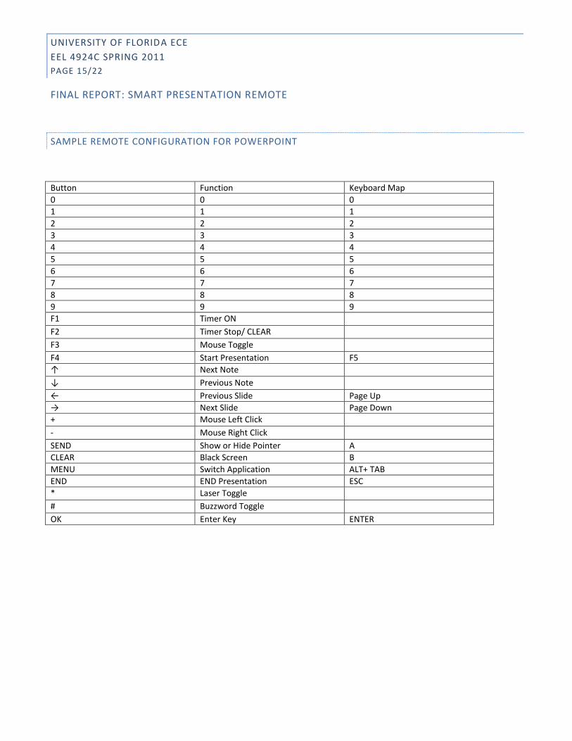
SAMPLE REMOTE CONFIGURATION FOR POWERPOINT
Button Function Keyboard Map 0 0 0 1 1 1 2 2 2 3 3 3 4 4 4 5 5 5 6 6 6 7 7 7 8 8 8 9 9 9 F1 Timer ON F2 Timer Stop/ CLEAR F3 Mouse Toggle F4 Start Presentation F5 ↑ Next Note ↓ Previous Note ← Previous Slide Page Up → Next Slide Page Down + Mouse Left Click - Mouse Right Click SEND Show or Hide Pointer A CLEAR Black Screen B MENU Switch Application ALT+ TAB END END Presentation ESC * Laser Toggle # Buzzword Toggle OK Enter Key ENTER

UNIVERSITY OF FLORIDA ECE
EEL 4924C SPRING 2011
PAGE 16/22
FINAL REPORT: SMART PRESENTATION REMOTE
APPENDIX B:PCB SCHEMATICS AND LAYOUTS

UNIVERSITY OF FLORIDA ECE
EEL 4924C SPRING 2011
PAGE 17/22
FINAL REPORT: SMART PRESENTATION REMOTE
Figure 5 Analog PCB

UNIVERSITY OF FLORIDA ECE
EEL 4924C SPRING 2011
PAGE 18/22
FINAL REPORT: SMART PRESENTATION REMOTE

UNIVERSITY OF FLORIDA ECE
EEL 4924C SPRING 2011
PAGE 19/22
FINAL REPORT: SMART PRESENTATION REMOTE
Figure 6 Main PCB

UNIVERSITY OF FLORIDA ECE
EEL 4924C SPRING 2011
PAGE 20/22
FINAL REPORT: SMART PRESENTATION REMOTE
APPENDIX C: MICROCONTROLLER CODE /* Remote.c
This is the main source file for the remote application.
Margaret Garvan and Samuel Smith
EEL4924 Spring 2011
#define F_CPU 32000000UL
#include <stdio.h>
*/
#include <stdlib.h>
#include "clksys_driver.h"
#include "usart_driver.h"
#include "bluetooth.h"
#include "spi_driver.h"
//#include "hitachi_lcd.h"
#include "port_driver.h"
#include "accelerometer.h"
#include "string.h"
#include "glcd.h"
#include "stlcd.h"
#include "keypad.h"
#include "gyroscope.h"
//Initialize prototypes
void clock_init(void);
uint8_t ST7565_buffer[128*64/8];
char text_buffer[168];
int text_pointer;
gyro myGyro;
//accel myAccel;
uint8_t key;
int main(void)
{
clock_init();
bluetooth_init();
init_gyro();
st7565_init();
setup(); // for graphic LCD screen
init_keypad();
PORT_SetPinsAsOutput(&PORTA, 0x04); //Set PORTB as output for Laser
CTRL
init_rtc();
sei(); //enables interrupts
while(1)
{
myGyro = get_gyro();

UNIVERSITY OF FLORIDA ECE
EEL 4924C SPRING 2011
PAGE 21/22
FINAL REPORT: SMART PRESENTATION REMOTE
// PORT_SetPins( &PORTA, 0x04 );// ON LED (or laser)
}
return 0;
}
void clock_init(void)
//From Sparkfun sample code
{
CLKSYS_Enable( OSC_RC32MEN_bm ); //32MHz
CLKSYS_Prescalers_Config( CLK_PSADIV_1_gc, CLK_PSBCDIV_1_1_gc );
do {} while ( CLKSYS_IsReady( OSC_RC32MRDY_bm ) == 0 );
CLKSYS_Main_ClockSource_Select( CLK_SCLKSEL_RC32M_gc );
CLKSYS_Disable(OSC_RC2MCREF_bm);
CLKSYS_AutoCalibration_Enable(OSC_RC32MCREF_bm,1);
}
//Timer overflow interrupt routine running at 8 Hz
ISR(RTC_OVF_vect)
{
key = scan_keypad();
bluetooth_int(myGyro.x);
bluetooth_char(' ');
bluetooth_int(myGyro.y);
bluetooth_char(' ');
bluetooth_int(myGyro.z);
bluetooth_char(' ');
bluetooth_int(key);
bluetooth_char('\r');
bluetooth_char('\n');
//bluetooth_receive();
}
ISR(USARTD0_RXC_vect){
char value = USARTD0.DATA;
if(text_pointer >= 168)
text_pointer = 0; //prevent buffer overflow
if (value == 0x03){ //clears text buffer
for(int i = 0; i< 168; i++ ){
text_buffer[i] = ' ';
}
text_pointer=0;
return;

UNIVERSITY OF FLORIDA ECE
EEL 4924C SPRING 2011
PAGE 22/22
FINAL REPORT: SMART PRESENTATION REMOTE
}
else if(value == 0x05){ //Laser Toggle
PORT_TogglePins( &PORTA, 0x04 );// toggle LED (or laser)
}
else if(value == 0x06){ //Laser ON
PORT_SetPins( &PORTA, 0x04 );// ON LED (or laser)
}
else if(value == 0x07){ //Laser OFF
PORT_ClearPins( &PORTA, 0x04 );// OFF LED (or laser)
}
else if(value == '\n'){
text_pointer = (text_pointer/21 + 1) * 21;
}
else if(value == 0x04){
clear_buffer(ST7565_buffer);
drawstring(ST7565_buffer, 0,0, text_buffer);
write_buffer(ST7565_buffer);
}
else if(value == 0x0D){
text_pointer = (text_pointer/21 ) * 21;
}
else
{
text_buffer[text_pointer++] = value;
}
}