Embed Size (px)
Citation preview
ABSTRACT
Title of document: REAL-TIME DECISION AID DISPLAY
Jennifer Au, Anthony Bonomo, Laura FreymanBrian Kwong, Benjamin Li, Jessica LiebermanLevon Mkrtchyan, Michael Price, Andrew SkodaMary Tellers, Andrew Tomaschko, Johnny Wu
Directed by: Dr. Frederick W. Mowrer, Associate Professor EmeritusDepartment of Fire Protection Engineering
Fire sensor systems effectively monitor the state of the building, detect fire,
and alert occupants in the event of an emergency. However, fire sensor technology
is limited in its ability to convey information to firefighters. Even though all of the
necessary information can be obtained through Fire Annunciator Control Panels
(FACPs), it is difficult to use them to track the progression of fire.
We designed and prototyped a decision aid system to illustrate our approach
to this problem. Our goal was to create a tactical decision aid display that can
present building information through an intuitive interface in real time. We used
previous research on the information needs of firefighters in designing the interface.
Our key insight was to use a floor plan with a sensor information overlay to organize
information. We implemented a prototype that interfaces with FACPs using existing
facilities systems management communication protocols.

REAL-TIME DECISION AID DISPLAY
by
Team Future Firefighting Advancements (FFA)Jennifer Au, Anthony Bonomo, Laura FreymanBrian Kwong, Benjamin Li, Jessica Lieberman
Levon Mkrtchyan, Michael Price, Andrew SkodaMary Tellers, Andrew Tomaschko, Johnny Wu
Thesis submitted in partial fulfillment of theGemstone Program, University of Maryland, 2011
Advisory Committee:Dr. Frederick W. Mowrer, ChairMr. Millard B. HolmesDr. James A. Milke, Ph.D. P.E.Dr. James PurtiloDr. Peter B. SunderlandMr. Scott Wood

c© Copyright byTeam FFA
Jennifer Au, Anthony Bonomo, Laura FreymanBrian Kwong, Benjamin Li, Jessica Lieberman
Levon Mkrtchyan, Michael Price, Andrew SkodaMary Tellers, Andrew Tomaschko, Johnny Wu
2011

Acknowledgments
We would like to thank SFPE ESF for their generous grant and the opportunity
to present at the SFPE conference. In addition, on campus we’d like to thank David
Doucette, Jim Robinson, and Olga Zeller for their time, patience, and helpfulness
throughout the project, as well as other facilities management staff who lent their
time. We are also grateful to Millard Holmes and SimplexGrinnell for the donation
of hardware and the expertise to help us configure it for our project. We would also
like to thank Honeywell for their donation of hardware as well. We also appreciate
the Gemstone program’s support throughout this four-year process. Finally, we
would like to thank the Fire Protection Engineering Department for the space they
gave us for meetings and lab work.
ii
Table of Contents
Acknowledgments ii
Table of Contents iii
List of Figures vi
List of Abbreviations viii
1 Introduction 1
2 Literature Review 72.1 Fire Emergency Responder Standard Operating Procedures . . . . . . 7
2.1.1 Size-Up . . . . . . . . . . . . . . . . . . . . . . . . . . . . . . 72.1.2 Operations - High-Rise Buildings . . . . . . . . . . . . . . . . 10
2.2 NFPA Standards . . . . . . . . . . . . . . . . . . . . . . . . . . . . . 132.3 BACnet . . . . . . . . . . . . . . . . . . . . . . . . . . . . . . . . . . 152.4 Building Tactical Information Project . . . . . . . . . . . . . . . . . . 172.5 FireGrid . . . . . . . . . . . . . . . . . . . . . . . . . . . . . . . . . . 272.6 Current Building Technology . . . . . . . . . . . . . . . . . . . . . . . 28
2.6.1 Overview . . . . . . . . . . . . . . . . . . . . . . . . . . . . . 282.6.2 Major Companies of the Fire Alarm and Detection Industry . 29
2.6.2.1 SimplexGrinnell . . . . . . . . . . . . . . . . . . . . 292.6.2.2 Honeywell International, Inc. . . . . . . . . . . . . . 332.6.2.3 Siemens AG . . . . . . . . . . . . . . . . . . . . . . . 36
2.6.3 Other Relevant Technology . . . . . . . . . . . . . . . . . . . 382.6.3.1 Keltron . . . . . . . . . . . . . . . . . . . . . . . . . 38
2.7 Current Firefighter Technology . . . . . . . . . . . . . . . . . . . . . 392.7.1 Pre-planning Software . . . . . . . . . . . . . . . . . . . . . . 402.7.2 Locator and Vital Sign Indicator Technology . . . . . . . . . . 41
2.8 Human Factors . . . . . . . . . . . . . . . . . . . . . . . . . . . . . . 432.8.1 Decision Support Systems (DSS) . . . . . . . . . . . . . . . . 442.8.2 GUI Design . . . . . . . . . . . . . . . . . . . . . . . . . . . . 50
3 Methodology 533.1 Case Study Methodology . . . . . . . . . . . . . . . . . . . . . . . . . 533.2 System Design . . . . . . . . . . . . . . . . . . . . . . . . . . . . . . . 54
3.2.1 Assessing EFR Needs . . . . . . . . . . . . . . . . . . . . . . . 543.2.2 Evaluation of Prior Work . . . . . . . . . . . . . . . . . . . . . 563.2.3 Design Goals and Basic Layout . . . . . . . . . . . . . . . . . 593.2.4 Final GUI Design . . . . . . . . . . . . . . . . . . . . . . . . . 60
3.3 Software Implementation . . . . . . . . . . . . . . . . . . . . . . . . . 633.3.1 Software Design Choices . . . . . . . . . . . . . . . . . . . . . 633.3.2 Annotation Tool . . . . . . . . . . . . . . . . . . . . . . . . . 64
iii

3.4 Hardware Testing . . . . . . . . . . . . . . . . . . . . . . . . . . . . . 653.4.1 Overview . . . . . . . . . . . . . . . . . . . . . . . . . . . . . 653.4.2 Panel Output Protocols . . . . . . . . . . . . . . . . . . . . . 673.4.3 Hardware and Scenario Mockup . . . . . . . . . . . . . . . . . 683.4.4 Procedure . . . . . . . . . . . . . . . . . . . . . . . . . . . . . 70
3.4.4.1 Analysis . . . . . . . . . . . . . . . . . . . . . . . . . 703.5 Fire Dynamics Simulator Tests . . . . . . . . . . . . . . . . . . . . . 71
3.5.1 FDS Overview . . . . . . . . . . . . . . . . . . . . . . . . . . . 713.5.2 Simulations . . . . . . . . . . . . . . . . . . . . . . . . . . . . 723.5.3 Testing Procedure . . . . . . . . . . . . . . . . . . . . . . . . . 74
3.5.3.1 Test 1 . . . . . . . . . . . . . . . . . . . . . . . . . . 753.5.3.2 Test 2 . . . . . . . . . . . . . . . . . . . . . . . . . . 75
4 Results 764.1 Hardware Test . . . . . . . . . . . . . . . . . . . . . . . . . . . . . . . 76
4.1.1 Honeywell Mockup Test . . . . . . . . . . . . . . . . . . . . . 764.1.2 SimplexGrinnell Mockup Test . . . . . . . . . . . . . . . . . . 774.1.3 Fire Progression . . . . . . . . . . . . . . . . . . . . . . . . . . 784.1.4 Analysis . . . . . . . . . . . . . . . . . . . . . . . . . . . . . . 81
4.2 FDS Testing of GUI . . . . . . . . . . . . . . . . . . . . . . . . . . . 834.2.1 Test 1 Results . . . . . . . . . . . . . . . . . . . . . . . . . . . 83
4.2.1.1 JMP Scenario . . . . . . . . . . . . . . . . . . . . . . 834.2.1.2 Multilevel Scenario . . . . . . . . . . . . . . . . . . . 86
4.2.2 Test 2 Results . . . . . . . . . . . . . . . . . . . . . . . . . . . 864.2.2.1 Start of incident . . . . . . . . . . . . . . . . . . . . 874.2.2.2 Flow switch activation: Four minutes from start of fire 884.2.2.3 All smoke sensors in alarm: Eight minutes from start
of fire . . . . . . . . . . . . . . . . . . . . . . . . . . 894.2.2.4 All sensors in alarm for sparse case: Twelve minutes
from start of fire . . . . . . . . . . . . . . . . . . . . 90
5 Conclusions 915.0.3 Future Directions . . . . . . . . . . . . . . . . . . . . . . . . . 92
A Features List 97
B Hardware Test: Emergency Scenario 102
C Sensor Triggering Testing 105
D FDS Test 1: Full Results 108D.1 Side by Side comparison of JMP simulation to GUI . . . . . . . . . . 108D.2 Side by Side comparison of Multilevel simulation to GUI . . . . . . . 114
iv

E FDS Code 116E.1 JMP FDS code . . . . . . . . . . . . . . . . . . . . . . . . . . . . . . 116E.2 Multi-level FDS code . . . . . . . . . . . . . . . . . . . . . . . . . . . 119
F Prototype Source Code 121
References 225
v
List of Figures
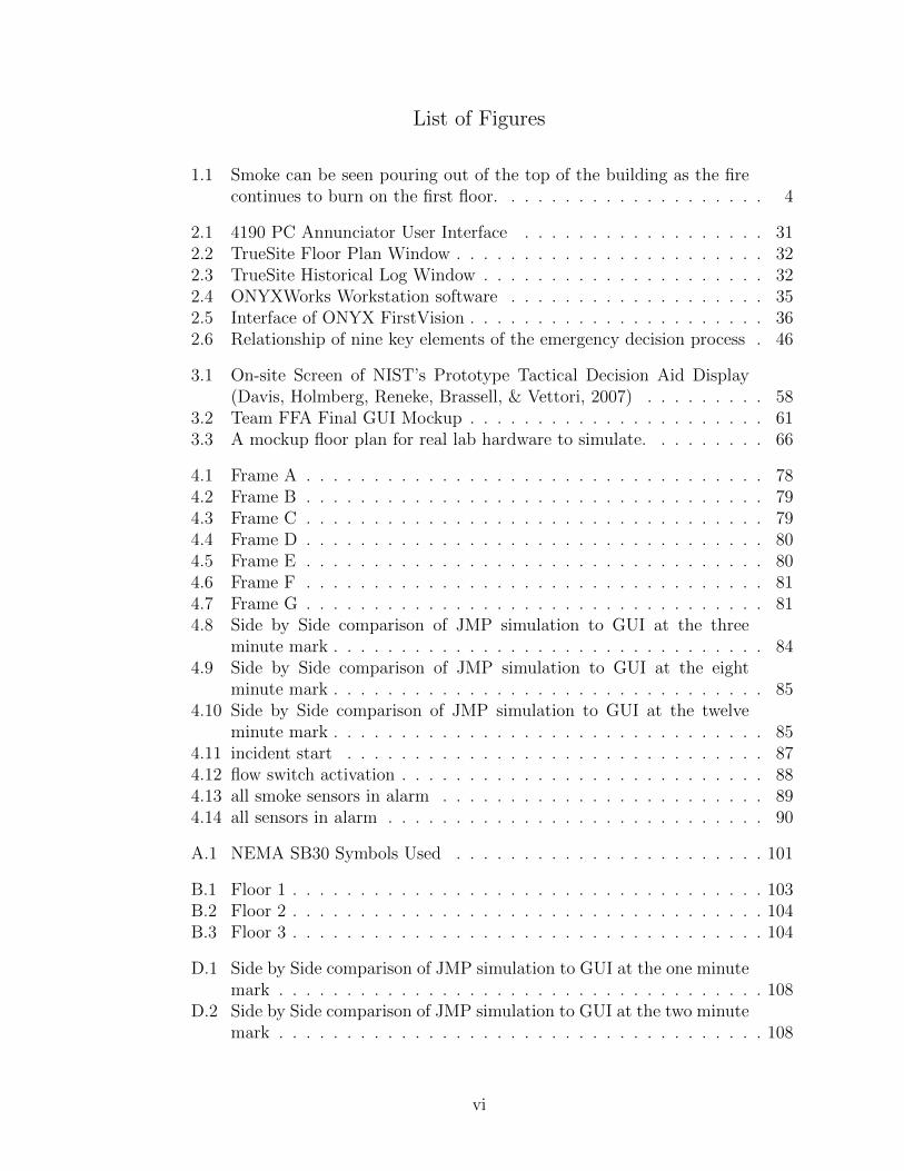
1.1 Smoke can be seen pouring out of the top of the building as the firecontinues to burn on the first floor. . . . . . . . . . . . . . . . . . . . 4
2.1 4190 PC Annunciator User Interface . . . . . . . . . . . . . . . . . . 312.2 TrueSite Floor Plan Window . . . . . . . . . . . . . . . . . . . . . . . 322.3 TrueSite Historical Log Window . . . . . . . . . . . . . . . . . . . . . 322.4 ONYXWorks Workstation software . . . . . . . . . . . . . . . . . . . 352.5 Interface of ONYX FirstVision . . . . . . . . . . . . . . . . . . . . . . 362.6 Relationship of nine key elements of the emergency decision process . 46
3.1 On-site Screen of NIST’s Prototype Tactical Decision Aid Display(Davis, Holmberg, Reneke, Brassell, & Vettori, 2007) . . . . . . . . . 58
3.2 Team FFA Final GUI Mockup . . . . . . . . . . . . . . . . . . . . . . 613.3 A mockup floor plan for real lab hardware to simulate. . . . . . . . . 66
4.1 Frame A . . . . . . . . . . . . . . . . . . . . . . . . . . . . . . . . . . 784.2 Frame B . . . . . . . . . . . . . . . . . . . . . . . . . . . . . . . . . . 794.3 Frame C . . . . . . . . . . . . . . . . . . . . . . . . . . . . . . . . . . 794.4 Frame D . . . . . . . . . . . . . . . . . . . . . . . . . . . . . . . . . . 804.5 Frame E . . . . . . . . . . . . . . . . . . . . . . . . . . . . . . . . . . 804.6 Frame F . . . . . . . . . . . . . . . . . . . . . . . . . . . . . . . . . . 814.7 Frame G . . . . . . . . . . . . . . . . . . . . . . . . . . . . . . . . . . 814.8 Side by Side comparison of JMP simulation to GUI at the three
minute mark . . . . . . . . . . . . . . . . . . . . . . . . . . . . . . . . 844.9 Side by Side comparison of JMP simulation to GUI at the eight
minute mark . . . . . . . . . . . . . . . . . . . . . . . . . . . . . . . . 854.10 Side by Side comparison of JMP simulation to GUI at the twelve
minute mark . . . . . . . . . . . . . . . . . . . . . . . . . . . . . . . . 854.11 incident start . . . . . . . . . . . . . . . . . . . . . . . . . . . . . . . 874.12 flow switch activation . . . . . . . . . . . . . . . . . . . . . . . . . . . 884.13 all smoke sensors in alarm . . . . . . . . . . . . . . . . . . . . . . . . 894.14 all sensors in alarm . . . . . . . . . . . . . . . . . . . . . . . . . . . . 90
A.1 NEMA SB30 Symbols Used . . . . . . . . . . . . . . . . . . . . . . . 101
B.1 Floor 1 . . . . . . . . . . . . . . . . . . . . . . . . . . . . . . . . . . . 103B.2 Floor 2 . . . . . . . . . . . . . . . . . . . . . . . . . . . . . . . . . . . 104B.3 Floor 3 . . . . . . . . . . . . . . . . . . . . . . . . . . . . . . . . . . . 104
D.1 Side by Side comparison of JMP simulation to GUI at the one minutemark . . . . . . . . . . . . . . . . . . . . . . . . . . . . . . . . . . . . 108
D.2 Side by Side comparison of JMP simulation to GUI at the two minutemark . . . . . . . . . . . . . . . . . . . . . . . . . . . . . . . . . . . . 108
vi
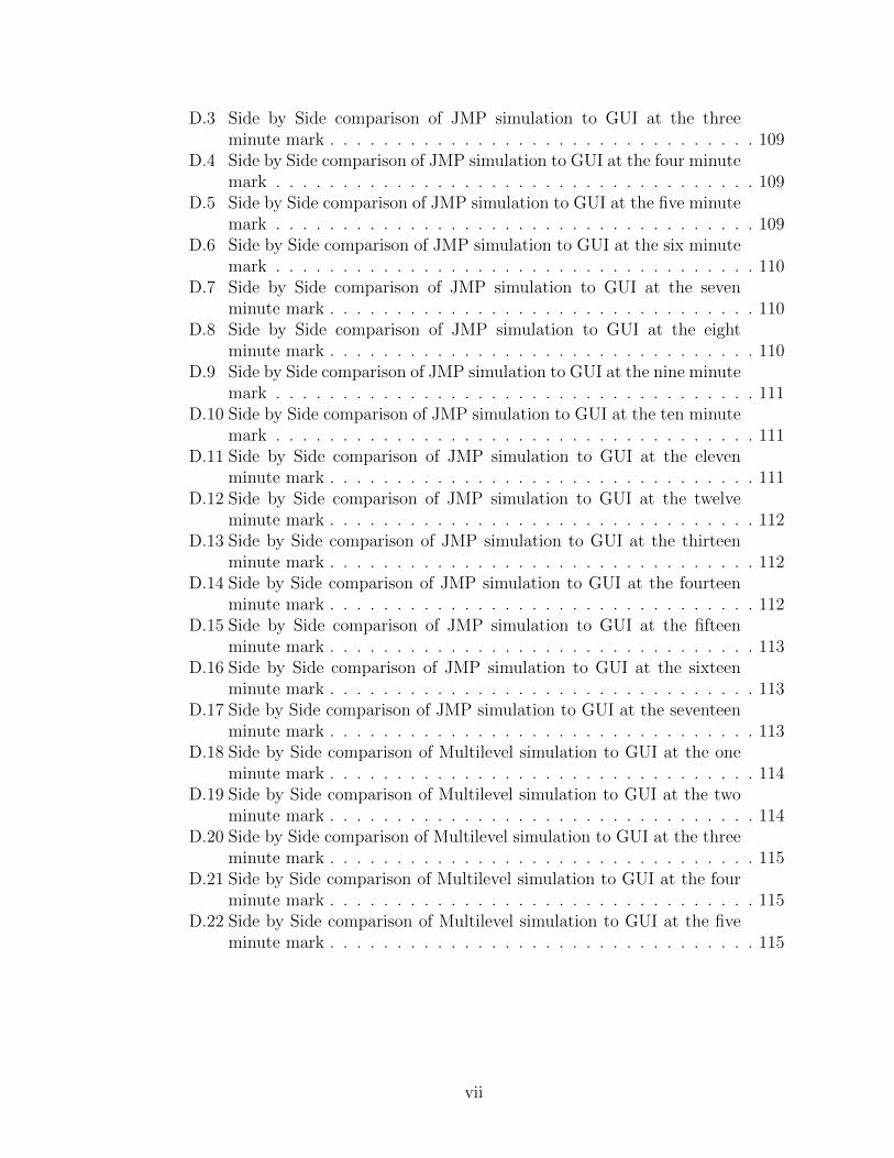
D.3 Side by Side comparison of JMP simulation to GUI at the threeminute mark . . . . . . . . . . . . . . . . . . . . . . . . . . . . . . . . 109
D.4 Side by Side comparison of JMP simulation to GUI at the four minutemark . . . . . . . . . . . . . . . . . . . . . . . . . . . . . . . . . . . . 109
D.5 Side by Side comparison of JMP simulation to GUI at the five minutemark . . . . . . . . . . . . . . . . . . . . . . . . . . . . . . . . . . . . 109
D.6 Side by Side comparison of JMP simulation to GUI at the six minutemark . . . . . . . . . . . . . . . . . . . . . . . . . . . . . . . . . . . . 110
D.7 Side by Side comparison of JMP simulation to GUI at the sevenminute mark . . . . . . . . . . . . . . . . . . . . . . . . . . . . . . . . 110
D.8 Side by Side comparison of JMP simulation to GUI at the eightminute mark . . . . . . . . . . . . . . . . . . . . . . . . . . . . . . . . 110
D.9 Side by Side comparison of JMP simulation to GUI at the nine minutemark . . . . . . . . . . . . . . . . . . . . . . . . . . . . . . . . . . . . 111
D.10 Side by Side comparison of JMP simulation to GUI at the ten minutemark . . . . . . . . . . . . . . . . . . . . . . . . . . . . . . . . . . . . 111
D.11 Side by Side comparison of JMP simulation to GUI at the elevenminute mark . . . . . . . . . . . . . . . . . . . . . . . . . . . . . . . . 111
D.12 Side by Side comparison of JMP simulation to GUI at the twelveminute mark . . . . . . . . . . . . . . . . . . . . . . . . . . . . . . . . 112
D.13 Side by Side comparison of JMP simulation to GUI at the thirteenminute mark . . . . . . . . . . . . . . . . . . . . . . . . . . . . . . . . 112
D.14 Side by Side comparison of JMP simulation to GUI at the fourteenminute mark . . . . . . . . . . . . . . . . . . . . . . . . . . . . . . . . 112
D.15 Side by Side comparison of JMP simulation to GUI at the fifteenminute mark . . . . . . . . . . . . . . . . . . . . . . . . . . . . . . . . 113
D.16 Side by Side comparison of JMP simulation to GUI at the sixteenminute mark . . . . . . . . . . . . . . . . . . . . . . . . . . . . . . . . 113
D.17 Side by Side comparison of JMP simulation to GUI at the seventeenminute mark . . . . . . . . . . . . . . . . . . . . . . . . . . . . . . . . 113
D.18 Side by Side comparison of Multilevel simulation to GUI at the oneminute mark . . . . . . . . . . . . . . . . . . . . . . . . . . . . . . . . 114
D.19 Side by Side comparison of Multilevel simulation to GUI at the twominute mark . . . . . . . . . . . . . . . . . . . . . . . . . . . . . . . . 114
D.20 Side by Side comparison of Multilevel simulation to GUI at the threeminute mark . . . . . . . . . . . . . . . . . . . . . . . . . . . . . . . . 115
D.21 Side by Side comparison of Multilevel simulation to GUI at the fourminute mark . . . . . . . . . . . . . . . . . . . . . . . . . . . . . . . . 115
D.22 Side by Side comparison of Multilevel simulation to GUI at the fiveminute mark . . . . . . . . . . . . . . . . . . . . . . . . . . . . . . . . 115
vii

List of Abbreviations
Antibody Identification Assistant (AIDA)The American Society of Heating, Refrigeration, and Air-conditioning Engineers(ASHRAE)Building automation system (BAS)Building information services and control system (BISACS)Building services interface (BSI)Chemical, biological, radiation (CBR)Command Decision Support Interface (CODSI)Comma-separated value (CSV)Decision support system (DSS)Emergency first responders (EFRs)Fire Alarm Control Panel (FACP)Fire Dynamics Simulator (FDS)Future Firefighting Advancements (FFA)Geographic information system (GIS)Gallons per minute (gpm)Global positioning system (GPS)Graphical user interface (GUI)Hazardous materials (hazmats)Human-computer interaction (HCI)Incident commanders (ICs)James M. Patterson (JMP)Maryland Fire and Rescue Institute (MFRI)National Electrical Manufacturers Association (NEMA)National Fire Protection Association (NFPA)National Institute of Standards and Technology (NIST)Occupational Safety and Health Administration (OSHA)Personal Identity Verification (PIV)Regional Crime Analysis Program (RECAP)Radio-frequency identification (RFID)Records management system (RMS)Self-contained breathing apparatus (SCBA)Sensor Driven Fire Model (SDFM)Society of Fire Protection Engineers (SFPE)SFPE Education and Scientific Foundation (SFPE ESF)Signaling line circuit (SLC)Ultra wideband (UWB)Very Early Smoke Detection Apparatus (VESDA)Extensible markup language (XML)
viii

Chapter 1
Introduction
For decades, building sensor manufacturers have pursued the goal of detecting
emergency situations earlier while reducing the occurrence of nuisance alarms. In
this respect, great progress has been made. Modern building sensors are much more
reliable and accurate than their predecessors. At the same time, the goal of using
building sensors as an aid to emergency first responders (EFRs) has been given less
attention. Building sensor data could provide important information, and history
has shown that having that data in a timely manner could aid in emergency response.
The Pang Seattle Warehouse fire is an example of how having information
immediately can change the outcome of an emergency. The fire started on July
5, 1995 in the warehouse as a result of arson, and firefighters were deployed inside
the building in order to suppress the flames. The firefighters on the first floor were
able to successfully put out the fire in that area and believed that they had the
emergency under control. However, the fire raged on in the basement, with another
dispatched group of firefighters trying to suppress it. The firefighters on the first
level did not communicate with the firefighters on the lower level and vice versa, and
neither communicated with incident command. Consequently, neither the incident
commander nor the firefighters on the first floor had any idea that there was a raging
fire in the basement. There was a sudden collapse of the first floor of the warehouse,
1
resulting in the deaths of four firefighters (Routley, 1995).
If the information of where the fire was located was immediately available, the
incident commander would have been much more informed when formulating an
attack plan for the fire. The need for more pre-planning data, as well as more data
communication during an emergency was made very clear in this incident (Thiel,
1999).
The First Interstate Bank building fire in Los Angeles on May 4, 1988 is
another example of an incident where more information could have been provided
to the personnel involved. At the time, this incident was considered to be one of
the most devastating fires in history. The blaze destroyed four floors and damaged
a fifth, resulting in over $50 million in property damage. One person was killed, and
thirty-five occupants and fourteen firefighters were injured during the incident.
The fire, which is believed to have been caused by an electrical source, orig-
inated on the twelfth floor of the building. Shortly after, a manual pull station
was activated and silenced by security personnel within minutes; they believed the
alarm was the result of repair work being performed in the building. A series of
smoke detector alarms were activated next, but each one was also reset by security
personnel. Eventually, an employee went to twelfth floor to determine the source of
the alarms, only to be engulfed by the flames in the lobby. The multiple alarm resets
delayed the notification of the fire department, leading to a much larger fire by the
time firefighters arrived. This scenario is one where a display of the alarm history
may have been helpful to security personnel, who were unable to piece together the
multiple alarms and recognize the extent of the fire.
2
In addition, the main fire pumps were shut down, resulting in poor water
pressure in the first minutes of response. Firefighters eventually found the building
fire pumps, mainly because the sprinkler installation supervisor was present and
able to inform the incident commander of the existence of these pumps (Routley,
1998). In this case, critical static information could have been made available to
the incident commander prior to arriving on the scene, which would have prevented
any delays in response. Again, this highlights the need for more pre-planning data.
The MGM Grand Hotel fire took place on November 21, 1980. The fire began
early in the morning at approximately 7:15 AM. The blaze began as a result of an
electrical fault that had been smoldering in the walls of a deli on the first floor of
the hotel. The fire soon caused flashover in the deli, causing a fireball to expand
rapidly throughout the first floor casino at about nineteen feet per second (Puit,
2000). The casino was full of fuel for the fire, including a highly flammable adhesive
used to attach ceiling tiles. The fire had engulfed the first floor by the time the first
responders arrived to the scene four minutes after the start of the fire.
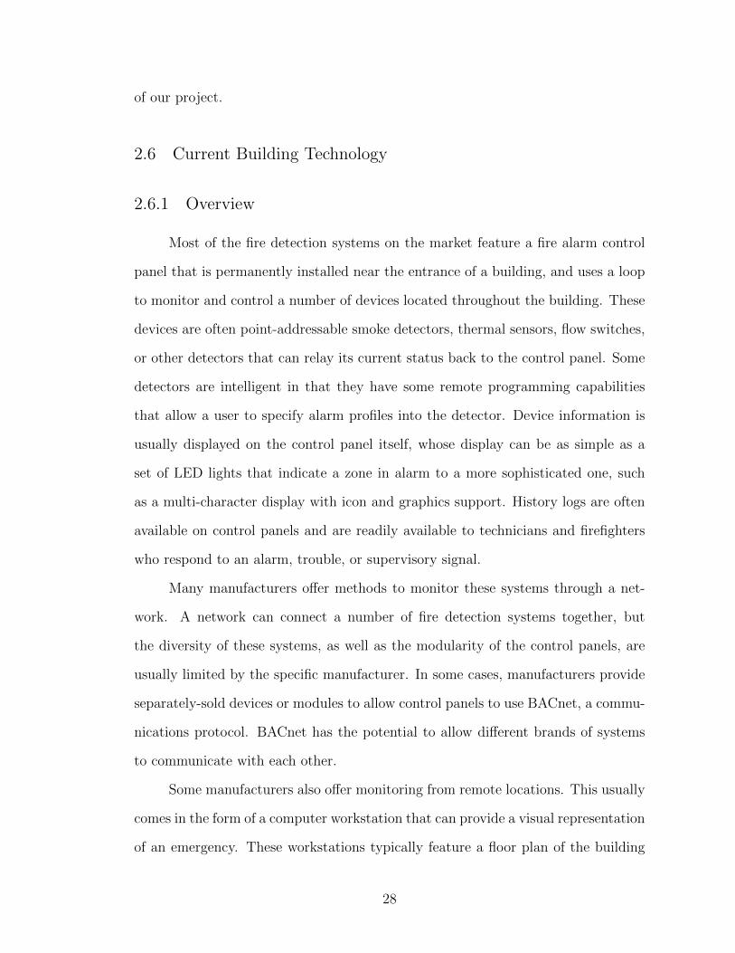
In Figure 1.1, copious amounts of smoke can be seen pouring from the build-
ing at the top and some of the sides. However, that smoke is the limit of visual
information that can be gained from an external view. While it may appear that
the fire has spread throughout the entire building by looking at the smoke, the
fire is only on the first floor. The massive amount of smoke generated by the fire
quickly rose through ventilation shafts, moved through the hallways in the top floor
and escaped out the windows. Because this smoke movement is very dependent on
environmental factors, it becomes hard to visually ascertain exactly where a fire is
3
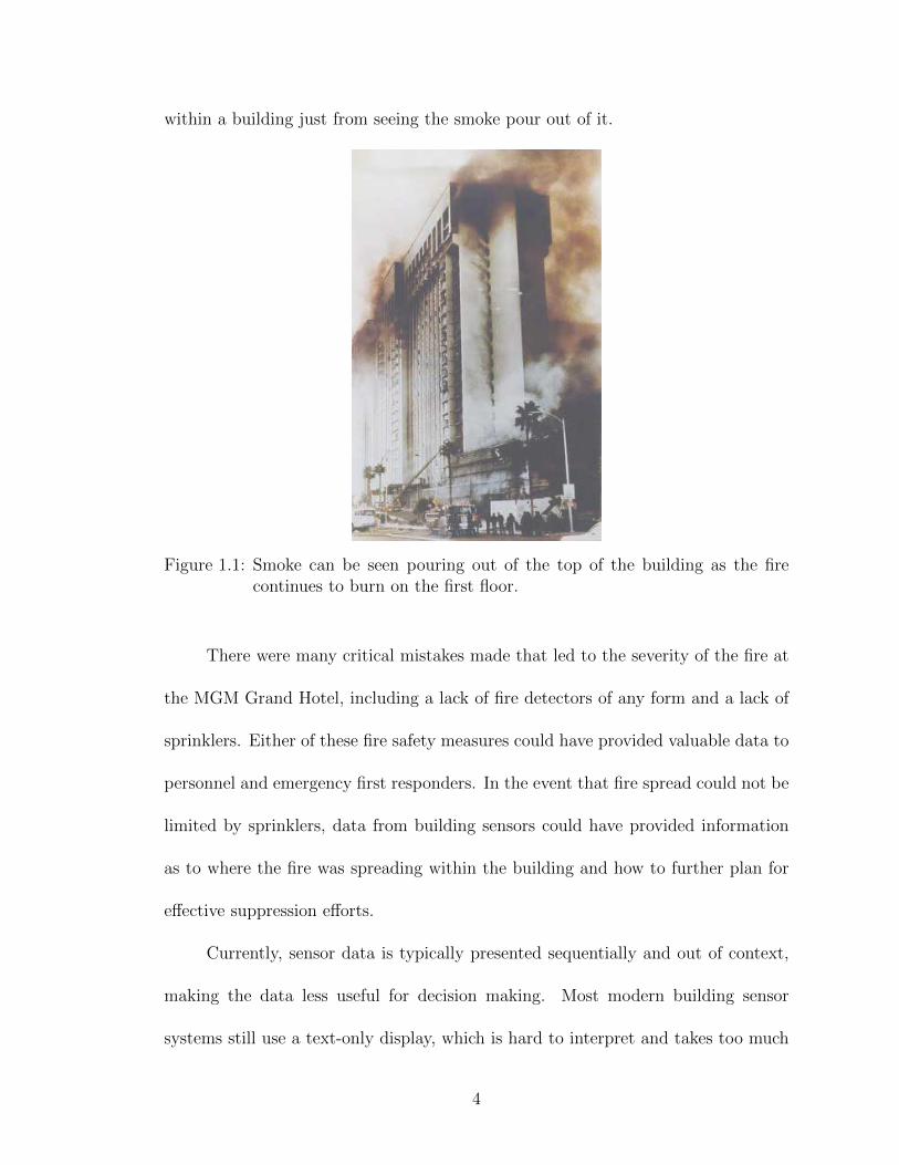
within a building just from seeing the smoke pour out of it.
Figure 1.1: Smoke can be seen pouring out of the top of the building as the firecontinues to burn on the first floor.
There were many critical mistakes made that led to the severity of the fire at
the MGM Grand Hotel, including a lack of fire detectors of any form and a lack of
sprinklers. Either of these fire safety measures could have provided valuable data to
personnel and emergency first responders. In the event that fire spread could not be
limited by sprinklers, data from building sensors could have provided information
as to where the fire was spreading within the building and how to further plan for
effective suppression efforts.
Currently, sensor data is typically presented sequentially and out of context,
making the data less useful for decision making. Most modern building sensor
systems still use a text-only display, which is hard to interpret and takes too much
4

effort to access and understand the information one is seeking. In order to assess
the situation in a building, it is necessary to contextualize the sensor data, that is
it must be presented in the context of related data. For example, the state of any
one sensor may not say much about the progression of smoke in the building but
the states of all of the smoke detectors on a floor does.
There are a number of barriers to contextualizing building data. Each sensor
manufacturer uses their own protocols for communication between sensors and the
annunciator panels. This lack of standardization makes it difficult to create a prod-
uct that can work with systems from different manufacturers. Another problem is
that, frequently, the sensor data is not easily obtained from the annunciator panel.
Retrieving analog sensor values such as room temperature and smoke obscuration
can be more difficult than simply obtaining sensor trouble or alarm states. The
extent of these problems was revealed during work on our project, but we did not
attempt to address them since there are known solutions.
Our team explored the approach of data contextualization through an emer-
gency visualization system. Overlaying data on a floorplan is the simplest way to
contextualize data. We focused on making the system useful as a decision support
tool during an emergency. We limited the prototype to only work with fire sensor
systems due to resource limitations, but intend the concept to be easily extensible
to all building sensor systems. In this thesis we describe the design, prototyping,
and evaluation of our system.
Our intent is for this project to serve as a proof-of-concept. We want to show
that building sensor data can be more useful when contextualized. The decision
5

support tool we developed demonstrates our approach to visualizing the state of a
building. Finally, we wanted to find out whether modern fire sensor systems can
be incorporated into such a visualization system without any changes to sensor
technology. To satisfy this goal we focused on the design stages of the process but
left the implementation as a prototype rather than as a finished product.
We are aware that in order to put a building state visualization system to
practical use, a number of infrastructure questions must be resolved. How are
building floor plans stored and made available for use in our system? Who annotates
the floor plans with sensor locations and when? How is the sensor data made
externally available without compromising security? How do EFRs incorporate use
of the system into their existing practices? It is not the aim of this thesis to address
any of these questions. These questions can be answered once a fully functional
decision support tool has been realized.
6
Chapter 2
Literature Review
2.1 Fire Emergency Responder Standard Operating Procedures
2.1.1 Size-Up
In order to effectively combat any fire emergency, firefighters are required to
obtain and process a great deal of information for every fire situation. According
to the Fire Officer’s Handbook of Tactics by John Norman, there is a thirteen-
point outline used by fire chiefs that covers a majority of fireground considerations,
conveniently summed up by the mnemonic COAL WAS WEALTH: Construction,
Occupancy, Apparatus and manpower, Life hazard, Water supply, Auxiliary appli-
ances, Street conditions, Weather, Exposures, Area and height, Location and extent
of fire, Time, and Hazardous materials. These points are interrelated and each is
not simply considered separately when sizing up a fire situation.
Norman establishes that life hazard is the most important factor in deter-
mining fire operations and tactics. Life hazard comes in two forms - civilians and
firefighters. Tactics employed by firefighters will usually be more aggressive if there
are civilians in need of rescue, but incident commanders (ICs) will not risk the safety
of firefighters if there is no significant civilian life hazard. Risk to civilian life is best
prevented before an incident occurs by imposing occupancy restrictions, specifying
7

fire doors and exits, and installing an automatic sprinkler system throughout the
building.
Occupancy has considerable bearing on life hazard, and is usually dependent
on the time of day and the type of building. For example, hospitals and residential
buildings create a high life hazard at all hours of the day, while storage warehouses
pose a uniformly low life hazard, while the life hazard of a school varies greatly with
the time of day. The time of year affects fire operations as well. Certain times of
year, such as the holiday season or hunting and fishing seasons in some regions, can
affect the amount of manpower available to ICs, especially in volunteer departments
(Norman, 2005).
Another important aspect of time in fire operations is the elapsed time of a fire
incident. ICs have some rules of thumb to gauge how long a fire has been burning
before their arrival to the fire situation, such as looking to see if fire is venting
out of windows, but these are typically inexact and require very experienced ICs
to implement these rules based on any given situation. ICs also have mechanisms
in place to track the time spent fighting a fire, such as the dispatcher requesting a
status report from the IC five minutes after arrival and every ten minutes for the
first hour of the incident (Norman, 2005).
Construction of the building is another important factor in determining the
fire tactics utilized by ICs. Buildings are classified into five general types: fire-
resistive, noncombustible, ordinary construction, heavy timber, and wood frame.
These classifications are based on four criteria: the degree of compartmentation a
building provides, the degree to which a building contributes to the fire load, the
8
number of hidden voids in the building, and the ability of the building to resist
collapse (Norman, 2005).
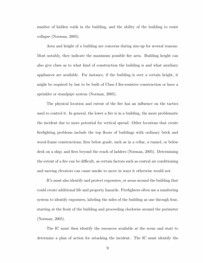
Area and height of a building are concerns during size-up for several reasons.
Most notably, they indicate the maximum possible fire area. Building height can
also give clues as to what kind of construction the building is and what auxiliary
appliances are available. For instance, if the building is over a certain height, it
might be required by law to be built of Class I fire-resistive construction or have a
sprinkler or standpipe system (Norman, 2005).
The physical location and extent of the fire has an influence on the tactics
used to control it. In general, the lower a fire is in a building, the more problematic
the incident due to more potential for vertical spread. Other locations that create
firefighting problems include the top floors of buildings with ordinary brick and
wood-frame constructions; fires below grade, such as in a cellar, a tunnel, or below
deck on a ship; and fires beyond the reach of ladders (Norman, 2005). Determining
the extent of a fire can be difficult, as certain factors such as central air conditioning
and moving elevators can cause smoke to move in ways it otherwise would not.
ICs must also identify and protect exposures, or areas around the building that
could create additional life and property hazards. Firefighters often use a numbering
system to identify exposures, labeling the sides of the building as one through four,
starting at the front of the building and proceeding clockwise around the perimeter
(Norman, 2005).
The IC must then identify the resources available at the scene and start to
determine a plan of action for attacking the incident. The IC must identify the
9
apparatus and manpower at his disposal and determine how to utilize them. Closely
related to these factors is the available water supply, which not only includes the
sources of water but also the devices and manpower used to transport the water to
extinguish the fire such as hoses and pumpers. ICs must also determine how much
water is needed to put out the fire, which is usually measured in gallons per minute
(gpm) based on the square footage of the fire. This can range from 10 gpm for 100
square feet of light fire load to 50 gpm for 100 square feet of heavy fire load. ICs
must also determine the presence and status of auxiliary appliances such as sprinkler
systems, standpipe systems, and foam suppression systems (Norman, 2005).
Several other factors should be accounted for when determining firefighting
tactics. Weather conditions can affect an IC’s strategy; high temperatures and
humidity will fatigue firefighters more quickly, while high winds might make ven-
tilation of a fire impractical. Certain street conditions such as construction and
illegally parked cars can hamper maneuvering and apparatus placement and uti-
lization. Hazardous materials (hazmats) present in and around a building present
a variety of problems, ranging from health hazards to acceleration of the fire ex-
tension. Identifying and attacking all of the above factors make the IC’s job very
challenging (Norman, 2005).
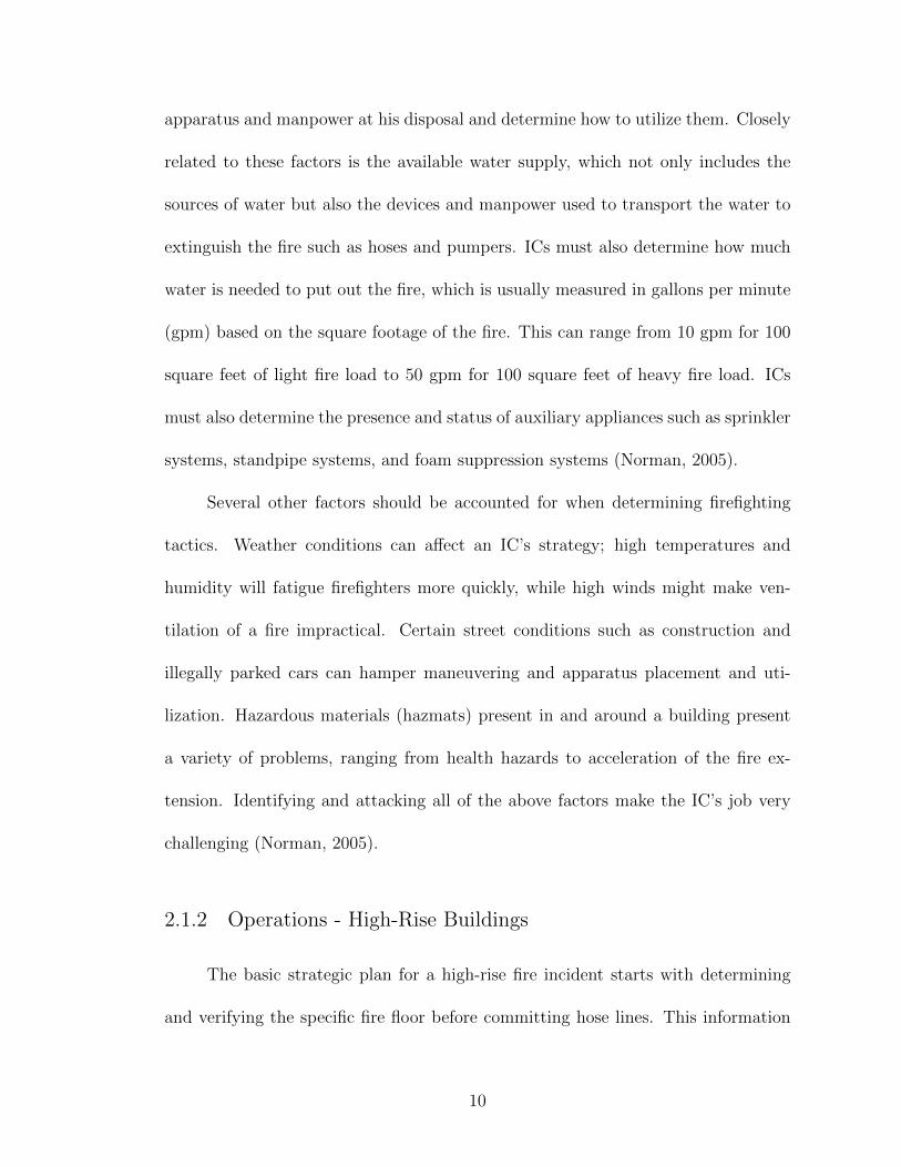
2.1.2 Operations - High-Rise Buildings
The basic strategic plan for a high-rise fire incident starts with determining
and verifying the specific fire floor before committing hose lines. This information
10
is critical but difficult to ascertain, as the initial information is often vague, such as
smoke seen from the fifth, sixth, and seventh floors. Next, firefighters must begin
a controlled evacuation, evacuating those in immediate danger first, preventing a
panicked exit by those not endangered, and searching the fire floor and all floors
above the fire. Firefighters must then gain control of the building systems, including
HVAC, elevators, public announcement, and other vital systems, and proceed to
confine and extinguish the fire (Norman, 2005).
A tremendous amount of resources and experience is required to fight a high-
rise building fire. In New York City, the signal of a possible working fire in a
high-rise calls for a deputy chief and four battalion chiefs to respond, and a second
alarm calls for another battalion chief, another deputy chief, and a senior staff
chief. The command post is usually set up in the lobby of the high-rise, while the
operations officer, usually one of the first responding chiefs other than the IC, goes
to the floor below the fire to assume direct command of the fire operations. The
operations officer must communicate constantly with the command post, keep the
line of attack moving forward and maintain resources (Norman, 2005).
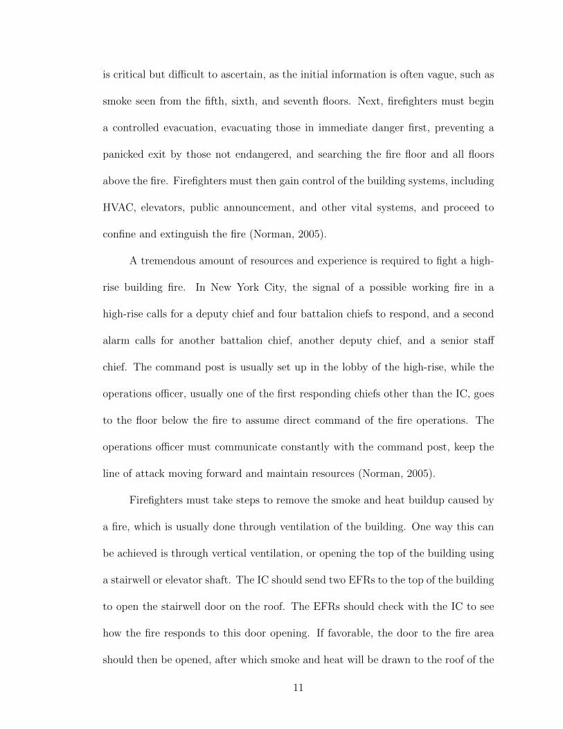
Firefighters must take steps to remove the smoke and heat buildup caused by
a fire, which is usually done through ventilation of the building. One way this can
be achieved is through vertical ventilation, or opening the top of the building using
a stairwell or elevator shaft. The IC should send two EFRs to the top of the building
to open the stairwell door on the roof. The EFRs should check with the IC to see
how the fire responds to this door opening. If favorable, the door to the fire area
should then be opened, after which smoke and heat will be drawn to the roof of the
11

building, with the stairwell acting as a chimney (Norman, 2005).
Another way to vent smoke, heat and gas out of the building is horizontal
ventilation. This technique involves breaking windows on the fire floor to allow
smoke to exit out the sides of the building. This tactic is much more complex than
vertical ventilation because if done improperly or in the wrong weather conditions,
it can cause smoke to blow into the building and upward to the top floors. This
tactic also has the added danger of glass falling to the street outside, which can
injure bystanders and fire personnel as well as sever hose lines. The IC should only
authorize horizontal ventilation after careful consideration (Norman, 2005).
After ventilation of the fire, gaining access to the fire area is the next fire-
fighting concern. For large high-rises, using the elevators is considered a ”necessary
evil” because a firefighter will not be very effective at fire suppression after walking
up over twenty stories carrying forcible entry tools, hoses, and other gear. Certain
safety precautions must be taken when using elevators in a fire situation, which
include attempting to accurately determine the fire floor, ensuring each team using
the elevator has been documented and properly equipped, using firemen’s service
elevators if possible, pressing the call cancel button when boarding to eliminate any
other selections made, and being prepared to don facemasks when arriving at the
destination. If elevators become unavailable, extra supplies must be transported
manually to the operations post. One firefighter would be assigned to transport
equipment for every two floors from ground floor to the fire floor. If there is not
enough fire personnel to transport equipment, non-fire personnel such as police can
be used as long as they are not put in threatening situations (Norman, 2005).
12
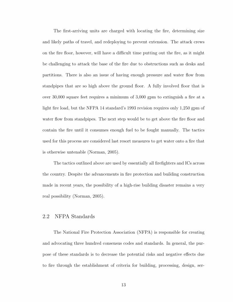
The first-arriving units are charged with locating the fire, determining size
and likely paths of travel, and redeploying to prevent extension. The attack crews
on the fire floor, however, will have a difficult time putting out the fire, as it might
be challenging to attack the base of the fire due to obstructions such as desks and
partitions. There is also an issue of having enough pressure and water flow from
standpipes that are so high above the ground floor. A fully involved floor that is
over 30,000 square feet requires a minimum of 3,000 gpm to extinguish a fire at a
light fire load, but the NFPA 14 standard’s 1993 revision requires only 1,250 gpm of
water flow from standpipes. The next step would be to get above the fire floor and
contain the fire until it consumes enough fuel to be fought manually. The tactics
used for this process are considered last resort measures to get water onto a fire that
is otherwise untenable (Norman, 2005).
The tactics outlined above are used by essentially all firefighters and ICs across
the country. Despite the advancements in fire protection and building construction
made in recent years, the possibility of a high-rise building disaster remains a very
real possibility (Norman, 2005).
2.2 NFPA Standards
The National Fire Protection Association (NFPA) is responsible for creating
and advocating three hundred consensus codes and standards. In general, the pur-
pose of these standards is to decrease the potential risks and negative effects due
to fire through the establishment of criteria for building, processing, design, ser-
13
vice, and installation (National Fire Protection Association, 2010). The NFPA uses
committees of volunteers from the fire protection industry to create and update
these standards. While wording from NFPA standards have been incorporated into
particular federal or state Occupational Safety and Health Administration (OSHA)
regulations, compliance with most of the three hundred codes and standards is vol-
untary unless adopted into law (National Volunteer Fire Council, n.d.). Three NFPA
standards, NFPA 72, NFPA 170 and NFPA 1620, are of particular significance to
our research project.
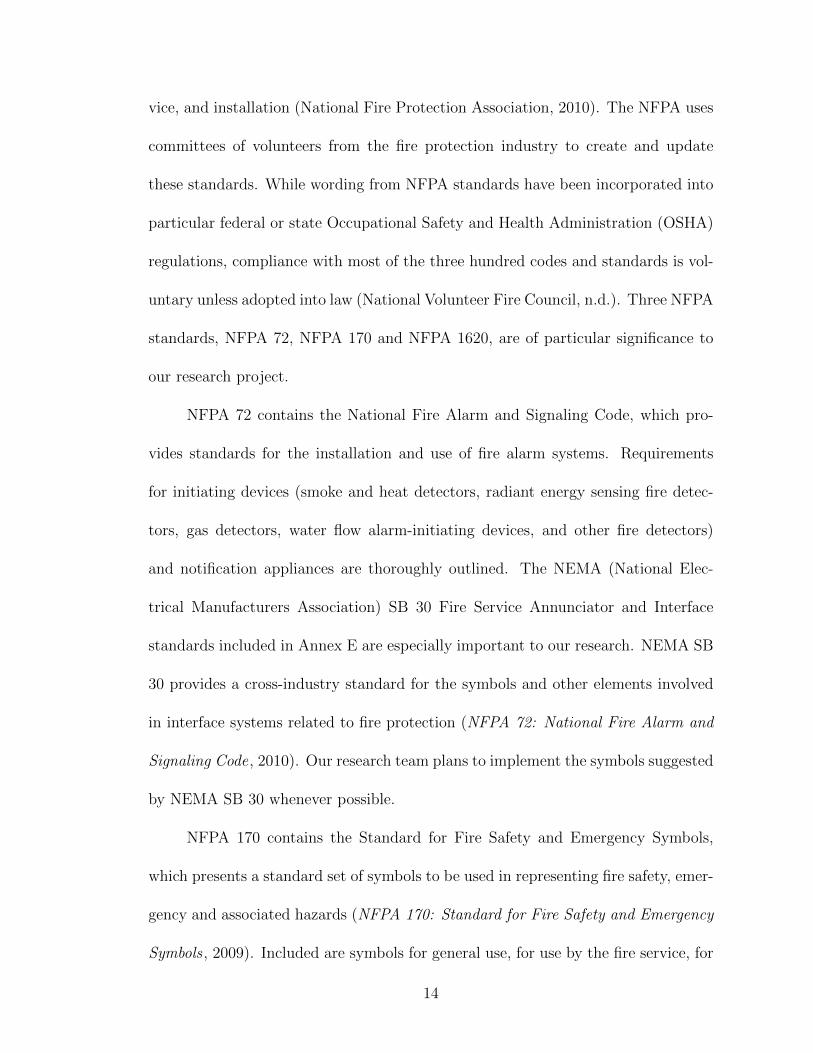
NFPA 72 contains the National Fire Alarm and Signaling Code, which pro-
vides standards for the installation and use of fire alarm systems. Requirements
for initiating devices (smoke and heat detectors, radiant energy sensing fire detec-
tors, gas detectors, water flow alarm-initiating devices, and other fire detectors)
and notification appliances are thoroughly outlined. The NEMA (National Elec-
trical Manufacturers Association) SB 30 Fire Service Annunciator and Interface
standards included in Annex E are especially important to our research. NEMA SB
30 provides a cross-industry standard for the symbols and other elements involved
in interface systems related to fire protection (NFPA 72: National Fire Alarm and
Signaling Code, 2010). Our research team plans to implement the symbols suggested
by NEMA SB 30 whenever possible.
NFPA 170 contains the Standard for Fire Safety and Emergency Symbols,
which presents a standard set of symbols to be used in representing fire safety, emer-
gency and associated hazards (NFPA 170: Standard for Fire Safety and Emergency
Symbols , 2009). Included are symbols for general use, for use by the fire service, for
14

use in architectural and engineering drawings and for use in pre-incident planning
sketches. We plan to use the symbols contained in NFPA 170 to augment Annex
E of NFPA 72, as NFPA 170 includes symbols for elements of a fire emergency not
addressed by the NEMA SB 30 standard.
NFPA 1620, the Standard for Pre-Incident Planning, establishes the essen-
tial features of any pre-planning system. It addresses the method of pre-planning,
occupancy, fire protection and suppression systems, specific hazards, emergency op-
erations and plan testing and maintenance. It also addresses the site evaluation and
other physical considerations. Some essential aspects of the building assessment por-
tion are construction, building management, external site conditions, and internal
and external security measures (NFPA 1620: Standard for pre-incident planning ,
2010). NFPA 1620 details exactly what information about a building needs to be in-
cluded in pre-planning materials. A standard like NFPA 1620 allows for cooperation
between multiple departments on the same event.
2.3 BACnet
In order to facilitate communications between our system and third-party pe-
ripherals, our team has decided to focus on using the BACnet protocol to receive and
interpret data output from building information systems. The BACnet protocol was
developed by ASHRAE, the American Society of Heating, Refrigeration, and Air-
conditioning Engineers in 1995 as a communications protocol to aid cross-platform
messaging between disparate building information systems(Bushby, 1996). It was
15

internationally recognized and formalized by the ISO standard 16484-5 in 2003.
Prior to the development of BACnet, building information systems exclusively used
proprietary communication protocols, and they were incapable of directly commu-
nicating or working with each other. Without a universal protocol like BACnet,
systems reading output from multiple building information systems, such as ours,
would be extremely difficult, if not impossible, to implement, for both technical
and legal reasons. The different protocols would have to be handled individually in
the code of the program to enable it to understand the output from the building
information systems, requiring a great deal of space, time, and effort to implement
an interpreter for each protocol. In addition, since these protocols are proprietary,
there could be legal issues associated with making such an interpreter, since it could
involve reverse-engineering these protocols to attain a sufficient understanding of
them (Newman, 2000).
BACnet is an object-oriented protocol with a client-server communications
paradigm. Sensors within a BACnet-compatible system are represented as “de-
vices.” Every device is made up of one or more “objects,” which encapsulate a
specific function of that device, such as binary input or analog output. These ob-
jects contain properties which represent the state of that function, such as whether
it is in alarm, or the value of an analog sensor. These properties are accessed by
the BACnet server through “services,” which query the objects about the state of
their properties. Every BACnet object can respond meaningfully to a subset of the
available services, with additional services supported as required (Bushby, 1996).
Sensors and systems that cannot natively communicate through BACnet can utilize
16
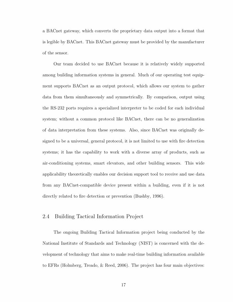
a BACnet gateway, which converts the proprietary data output into a format that
is legible by BACnet. This BACnet gateway must be provided by the manufacturer
of the sensor.
Our team decided to use BACnet because it is relatively widely supported
among building information systems in general. Much of our operating test equip-
ment supports BACnet as an output protocol, which allows our system to gather
data from them simultaneously and symmetrically. By comparison, output using
the RS-232 ports requires a specialized interpreter to be coded for each individual
system; without a common protocol like BACnet, there can be no generalization
of data interpretation from these systems. Also, since BACnet was originally de-
signed to be a universal, general protocol, it is not limited to use with fire detection
systems; it has the capability to work with a diverse array of products, such as
air-conditioning systems, smart elevators, and other building sensors. This wide
applicability theoretically enables our decision support tool to receive and use data
from any BACnet-compatible device present within a building, even if it is not
directly related to fire detection or prevention (Bushby, 1996).
2.4 Building Tactical Information Project
The ongoing Building Tactical Information project being conducted by the
National Institute of Standards and Technology (NIST) is concerned with the de-
velopment of technology that aims to make real-time building information available
to EFRs (Holmberg, Treado, & Reed, 2006). The project has four main objectives:
17
1) determining which data would be most useful to EFRs in emergency response
situations, 2) developing a standard method for dispersing the data collected by
buildings to EFRs, 3) demonstrating the effectiveness of the technology proposed
by the project and 4) addressing the security issues in the system proposed.
In order to make a system of complexity and sophistication that would be
capable of the goals of our project, it must be determined what information is key
to emergency response. To make a complex system for a target group of people
such as EFRs, it is a necessary step of product development to talk to the end users
to determine their needs and specifications. To this end, NIST held a workshop
for emergency responders to define what information they needed during a build-
ing emergency to aid them in making decisions. The results of this workshop are
presented in the paper entitled “Workshop to Define Information Needed for Emer-
gency First Responders During Building Emergencies,” by Jones, Holmberg, Davis,
Evans, Bushby, and Reed.
It is important for our project to have the feedback and information generated
by users from NIST’s workshop because it was conducted on a scale that would not
be feasible for a Gemstone Team. The following paragraphs introduce information
found from the workshop that directly pertains to specifications we need to address.
First, the participants in the workshop identified two essential categories of
information based on the time frame typically associated with emergency response:
“En-Route,” defined as the “first five minutes” and “On the Scene,” after the EFRs
arrive at the site of the emergency. These two time frames represent the important
phases of emergency response in which decisions are made. Second, the workshop
18

identified three major areas of information important to creating a system: static in-
formation, dynamic information, and the display of information. Static information
is defined as information available before an emergency occurs. This information
includes building plans, sensor layouts, and pre-established escape routes. Also in-
cluded are the more specific qualities of a structure such as where access points of
the building are, locations of elevators, nearby hazard conditions, and the types of
power systems that are running in the building. Dynamic information is defined
as the real-time information that would be received from the sensor systems. This
information includes direct sensor readings from building fire panels as well as in-
formation from decision support tools which take in and analyze data in order to
give a useful conclusion such as fire location and spread (Jones et al., 2005). All of
this information would have to be managed in a simple, yet comprehensive display.
For the En-Route display, to be used during the first five minutes of an emer-
gency when responders are on the way to the scene, a comprehensive list of static
and dynamic information to be displayed was decided on by the EFRs who took
part in the workshop. However, it was noted that given the circumstances of the
first five minutes, with the commander and other first responders all en-route to
the incident, only so much information could be effectively communicated due to
difficulties of reading from computers while in motion. With that in mind, a list of
static information was generated; aspects of this list that are relevant to our project
are presented below:
• Building condition (let burn, unsafe to enter, dangerous roof, sprinklered andother suppression systems)
19

• Building type (single family, commercial, gas storage, school)
• Building style (one story, two story, n story, auditorium, sublevels, etc.)
• Building construction (type I, II, III, IV or V; fire resistive, noncombustibleor limited combustible, ordinary, heavy timber, or wood frame)
• Roof construction (light weight metal or wood trusses)
• Hazardous materials or unusual hazards (above ground propane tank, gas lines,chemicals, etc.)
• Location of fire hydrants on map with building outline, nonstandard threadsizes included
• Location of fire department hookups for sprinkler system/standpipes
• Other sources of water nearby
• Location of staging areas and entrances and exits to building
• History of location in case fire stages before police arrive
• Routing information for emergency equipment to reach the building in case ofconstruction
(Jones et al., 2005)
Additionally, the dynamic information generated includes:
• Confidence in the incident being real (based on number of sensors in alarmand/or calculated fire size)
• Approximate location of fire within building
• Fire size and duration
• Sprinklers are flowing/no sprinklers or other working systems
• Fire growth (fast, medium, or slow)
• CBR (chemical, biological, radiation) sensors present and in alarm
• Police on the scene
• Presence of occupants in the building
• Stairwell smoke/heat conditions for positioning
• Standpipes to use to get to the fire
20
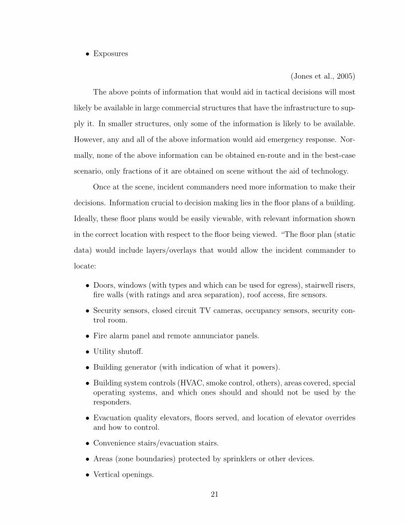
• Exposures
(Jones et al., 2005)
The above points of information that would aid in tactical decisions will most
likely be available in large commercial structures that have the infrastructure to sup-
ply it. In smaller structures, only some of the information is likely to be available.
However, any and all of the above information would aid emergency response. Nor-
mally, none of the above information can be obtained en-route and in the best-case
scenario, only fractions of it are obtained on scene without the aid of technology.
Once at the scene, incident commanders need more information to make their
decisions. Information crucial to decision making lies in the floor plans of a building.
Ideally, these floor plans would be easily viewable, with relevant information shown
in the correct location with respect to the floor being viewed. “The floor plan (static
data) would include layers/overlays that would allow the incident commander to
locate:
• Doors, windows (with types and which can be used for egress), stairwell risers,fire walls (with ratings and area separation), roof access, fire sensors.
• Security sensors, closed circuit TV cameras, occupancy sensors, security con-trol room.
• Fire alarm panel and remote annunciator panels.
• Utility shutoff.
• Building generator (with indication of what it powers).
• Building system controls (HVAC, smoke control, others), areas covered, specialoperating systems, and which ones should and should not be used by theresponders.
• Evacuation quality elevators, floors served, and location of elevator overridesand how to control.
• Convenience stairs/evacuation stairs.
• Areas (zone boundaries) protected by sprinklers or other devices.
• Vertical openings.
21
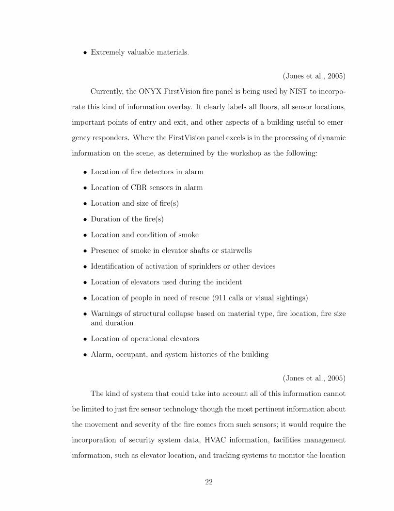
• Extremely valuable materials.
(Jones et al., 2005)
Currently, the ONYX FirstVision fire panel is being used by NIST to incorpo-
rate this kind of information overlay. It clearly labels all floors, all sensor locations,
important points of entry and exit, and other aspects of a building useful to emer-
gency responders. Where the FirstVision panel excels is in the processing of dynamic
information on the scene, as determined by the workshop as the following:
• Location of fire detectors in alarm
• Location of CBR sensors in alarm
• Location and size of fire(s)
• Duration of the fire(s)
• Location and condition of smoke
• Presence of smoke in elevator shafts or stairwells
• Identification of activation of sprinklers or other devices
• Location of elevators used during the incident
• Location of people in need of rescue (911 calls or visual sightings)
• Warnings of structural collapse based on material type, fire location, fire sizeand duration
• Location of operational elevators
• Alarm, occupant, and system histories of the building
(Jones et al., 2005)
The kind of system that could take into account all of this information cannot
be limited to just fire sensor technology though the most pertinent information about
the movement and severity of the fire comes from such sensors; it would require the
incorporation of security system data, HVAC information, facilities management
information, such as elevator location, and tracking systems to monitor the location
22
of EFRs within a building. A normal fire sensor system would be inadequate on
its own. However, fire sensor systems have an important component, the fire panel
annunciator, which, if sophisticated enough, can be used to process and analyze
information, and, given the right inputs, incorporate other system technologies by
using a common communication protocol such as BACnet.
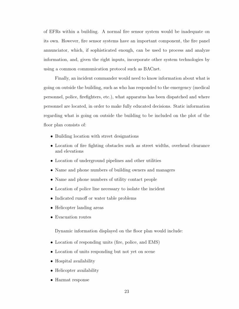
Finally, an incident commander would need to know information about what is
going on outside the building, such as who has responded to the emergency (medical
personnel, police, firefighters, etc.), what apparatus has been dispatched and where
personnel are located, in order to make fully educated decisions. Static information
regarding what is going on outside the building to be included on the plot of the
floor plan consists of:
• Building location with street designations
• Location of fire fighting obstacles such as street widths, overhead clearanceand elevations
• Location of underground pipelines and other utilities
• Name and phone numbers of building owners and managers
• Name and phone numbers of utility contact people
• Location of police line necessary to isolate the incident
• Indicated runoff or water table problems
• Helicopter landing areas
• Evacuation routes
Dynamic information displayed on the floor plan would include:
• Location of responding units (fire, police, and EMS)
• Location of units responding but not yet on scene
• Hospital availability
• Helicopter availability
• Hazmat response
23

• Location of police line necessary to isolate the incident
• Location of triage or evacuation area
• Suggested hazard perimeter
• Local weather conditions and predicted spread directions
• Wind direction and velocity
The data that could be provided and used by EFRs is extensive and the need
for a system that can distribute all of this information is very real. The needs
for EFRs in a building emergency determined by NIST’s workshop serve as the
backbone for the standards set for our system. There are, however, concerns that
must be considered in designing such a system. Specifically, standardization is a key
issue. EFRs expressed concerns with usability of a system, mentioning a need for
every system control display to be the same, so there is no new learning curve from
building to building, incident to incident. Also, the system has to be fully functional,
not partially, as the Fire Service will not adopt a new, questionable system. The
Fire Service cannot be expected to pay for new technology, thus the system must
also be affordable enough to be installed and used in real-time when buildings are
first constructed (Jones et al., 2005).
Further literature published by NIST addresses the remaining objectives of
the Building Tactical Information project. To address the second objective, NIST
proposes a building information server to provide access to tactical information in
real-time to EFRs (Holmberg et al., 2006). This tactical information includes static
building information on a given building’s construction, occupancy type, floor plans,
and system schematics, as well as dynamic information collected including alarms
and changes in a building’s status as they occur. According to the project, the
desirable features for such a building information server system include the ability
to:
• Forward alarms and status messages as they occur
24

• Deliver descriptive building information
• Allow only authorized access
• Allow authentication by multiple accessing connections
• Allow asynchronous access
• Present information in a common format
• Minimize the volume of transmitted information
• Maximize the use of layered communications protocols
• Continue to provide information in the event of partial system failure
The project also proposes the use of extensible markup language (XML) in
messages received and dispatched by the server in addition to the implementation
of the Internet TCP/IP suite as the base communication protocol (Holmberg et al.,
2006).
In addition to the implementation of a building information server, the project
also advocates the use of the Sensor Driven Fire Model (SDFM) support system.
The SDFM is a prototype decision support system that converts sensor signals to
predictions and issues warnings based on these predictions. In order to present
the information collected by the building information server and interpreted by
the SDFM system, the project proposes both en-route and on-scene information
presentation screens. The en-route screen provides information about the area in
the immediate vicinity of the building while the on-scene screen presents detailed
information about the building’s interior (Holmberg et al., 2006).
In February 2005, a demonstration of much of the technology described above
was held at NIST, accomplishing the project’s third objective. The demonstration
was documented on video. The presentation included demonstrations of building
sensor data and fire modeling data formatted in XML schema, the transfer of build-
ing data to the building information server, and the use of the proposed software
client and interface software. At the demonstration, it was determined that EFRs
25
often are not aware what information is available from the control systems con-
tained in buildings; an educational video was produced to address this deficiency
(Holmberg et al., 2006).
To accomplish the fourth objective of the Building Tactical Information Project,
NIST outlines a method for allowing only secure access to building information for
use in emergency response. The methodology described would permit public safety
officials remote access to real-time information. In addition, it would also grant
access to EFRs en-route (Treado, Vinh, Holmberg, & Galler, 2007).
As proposed, dynamic information would be provided to emergency personnel
through a building automation system, which coordinates the activities of HVAC,
lighting and access controllers, and fire detection and security systems. The sensor
data and video streams provided by these systems would be delivered to EFRs
through enhancements to the BACnet building automation system communication
protocol. Static information such as floor plans and equipment schematics would
already be available to public safety officials in building information models (Treado
et al., 2007).
To access the information being provided by the building automation system,
a secure proof-of-identity credential, such as a federal PIV (Personal Identity Veri-
fication) would be required. The right to varying levels of the hierarchical database
structure would be governed by factors such as identity, jurisdiction, duty status,
incident need, and chain-of-command. The secure connection to these databases
would be facilitated by a building information services and control system (BISACS),
a system lending itself to standardized protocols and secure communication. The
BISACS would be centrally located in a given building and credential reader inter-
faces at access nodes would permit authenticated internal and external user access.
A secure web-based link between the BISACS and the BACnet building automation
system (BAS) using a building services interface (BSI) would allow information and
26
resources to be exchanged and shared securely. To maintain security, information
would only be permitted to travel in one direction, from BAS to BISACS (Treado
et al., 2007).
The system proposed by the Building Tactical Information Project provided
a sound foundation for the design and implementation of our team’s own prototype
decision support tool. The prototype our team created aims to satisfy many of
the same design criteria. The background information utilized, data collected, and
results to date of the Building Tactical Information Project were invaluable to the
design of our decision support tool.
2.5 FireGrid
The FireGrid project, lead by the School of Engineering and Electronics at
the University of Edinburgh, is attempting to achieve the same goal we sought
to accomplish with our research project: provide firefighters with valuable building
sensor data in a usable format in real-time. However, unlike our project, the FireGrid
consortium has placed heavy emphasis on the modeling of a fire’s progression to
predict its future course using high performance computers, grid-enabled distributed
computing capabilities, computational fluid dynamics models, and finite element
structural models (Berry et al., 2005). According to Potter and Wickler (2008),
incident commanders would use one of two command and control interfaces to send
a request concerning the future development of a particular fire emergency to the
Query Manager which would search for available models that can answer the query,
run the most appropriate model to obtain the information requested, and return this
information to the incident commander. While the FireGrid consortium’s attempt
to integrate predictive modeling into a command and control decision support tool
for firefighters is certainly compelling, we feel that it is rather far-sighted and thus
did not find the work they are doing to be particularly helpful to the advancement
27
of our project.
2.6 Current Building Technology
2.6.1 Overview
Most of the fire detection systems on the market feature a fire alarm control
panel that is permanently installed near the entrance of a building, and uses a loop
to monitor and control a number of devices located throughout the building. These
devices are often point-addressable smoke detectors, thermal sensors, flow switches,
or other detectors that can relay its current status back to the control panel. Some
detectors are intelligent in that they have some remote programming capabilities
that allow a user to specify alarm profiles into the detector. Device information is
usually displayed on the control panel itself, whose display can be as simple as a
set of LED lights that indicate a zone in alarm to a more sophisticated one, such
as a multi-character display with icon and graphics support. History logs are often
available on control panels and are readily available to technicians and firefighters
who respond to an alarm, trouble, or supervisory signal.
Many manufacturers offer methods to monitor these systems through a net-
work. A network can connect a number of fire detection systems together, but
the diversity of these systems, as well as the modularity of the control panels, are
usually limited by the specific manufacturer. In some cases, manufacturers provide
separately-sold devices or modules to allow control panels to use BACnet, a commu-
nications protocol. BACnet has the potential to allow different brands of systems
to communicate with each other.
Some manufacturers also offer monitoring from remote locations. This usually
comes in the form of a computer workstation that can provide a visual representation
of an emergency. These workstations typically feature a floor plan of the building
28

that contains multiple icons that represent different types of signals and detectors.
The location of these workstations is fixed, since the computer is usually installed
in a specific area.
Other types of building technology are HVAC and other monitoring systems.
HVAC systems have been used to monitor fire alarm panels, with variable success.
Many of these have given way to systems like those of Keltron, which uses wireless
transceivers to monitor a variety of building systems through radio or Ethernet.
2.6.2 Major Companies of the Fire Alarm and Detection Industry
In the United States, Tyco International Ltd. is a major player in the secu-
rity, burglar, and fire alarm industry, making up 26.2 percent of the market share
(Culbert, 2010). Other major companies that play a role in this industry include
the Honeywell International, Siemens AG, and UTC Fire and Security.
2.6.2.1 SimplexGrinnell
The subsidiaries of Tyco International include several companies that manu-
facture safety, security, and electrical products, as well as SimplexGrinnell, which
manufactures many of the fire alarm systems in the United States. SimplexGrinnell’s
addressable fire alarm panels are the 4100U, the 4010, and the 4008 (Addressable
Fire Alarm Panels , 2011).
While the 4010 and 4008 panels are most applicable to small to mid-sized
buildings, the 4100U is designed for larger applications. It has a maximum capacity
of 2000 addressable points, with up to 250 points that support TrueAlarm sensors,
allowing sensor analog values to be communicated back to the control panel (Simplex
4100U Fire Alarm Control Panel , 2010). For TrueAlarm smoke sensors, the control
panel maintains a current value, peak value, and average value for each sensor and
tracks the status of each sensor by comparing the current values to the average value.
29

This allows the system to account for dirty sensors that could result in false alarms.
The 4100U also features a two-line by 40-character LCD display for information
readout, a numeric keypad, six system status indicator LEDs, three programmable
LEDs, and five programmable function switches. The panel’s alarm and trouble
signal history log can maintain up to 1,300 total events, which are viewable on the
LCD display or printed by connecting a printer to the panels RS-232 port.
The 4100U is also compatible with other communication devices, such as the
BACpac Ethernet module and the SafeLINC internet interface. The BACpac Eth-
ernet module converts data from the panel to the BACnet protocol, allowing com-
munication with other BACnet-compatible devices (BACPAC BACnet Products ,
2010). The module is connected to the panel through the RS-232 port and has an
output port for Ethernet LAN connection. The SafeLINC internet interface allows
devices such as personal computers and PDAs to remotely monitor the fire alarm
panels through an internet connection (SafeLINC Fire Panel Internet Interface,
2010). The module provides access for up to 20 different user accounts, but only
one user can access the interface at a single time. The interface is modeled after that
of an internet browser and includes a system snapshot of the control panel status,
access to history logs and reports, the local time, a side menu with additional links
and a page of panel details.
SimplexGrinnell also provides a line of annunciators that are compatible with
the 4100U. One particular annunciator is the 4190 PC annunciator. The interface
is text-based and essentially provides a printout of each sensor’s state as it changes.
Historical logs and reports are also accessible. Figure 2.1 shows its interface.
30

Figure 2.1: 4190 PC Annunciator User Interface
SimplexGrinnell’s other annunciator is called the TrueSite Workstation, which
provides a graphical display of the building’s floor plan and a textual display of
the alarm states (TrueSite Workstation with Multi-Client Capability , 2010). The
graphical display has navigational tools to view the floor plan in greater or lesser
detail and supports standard fire service annunciation icons. Custom alarm and
system messages, as well as historical logs, are viewable on the TrueSite Workstation.
Figure 2.2 and Figure 2.3 show both of the Workstation’s interfaces.
31

Figure 2.2: TrueSite Floor Plan Window
Figure 2.3: TrueSite Historical Log Window
SimplexGrinnell also manufactures initiating devices that are compatible with
its fire alarm panels (SimplexGrinnell Initiating Devices , 2011). This includes the
TrueAlarm sensors, manual pull stations, carbon monoxide detectors, and modules
that provide addressability to conventional devices. It also manufactures speciality
devices, such as an infrared smoke detector, a VESDA VLC-600 TrueAlarm Laser,
32
and a video smoke and flame detector which provides smoke and flame video in
real-time (SimplexGrinnell Specialized Detection Devices , 2011). The Very Early
Smoke Detection Apparatus (VESDA) periodically samples the air in an area for
smoke (VESDA VLC-600 TrueAlarm Laser COMPACT , 2010).
2.6.2.2 Honeywell International, Inc.
Honeywell has a number of subsidiaries that manufacture fire alarm systems.
These include Silent Knight, Fire Lite Alarms, Gamewell Fire Control Instruments
and Notifier. Notifier is one of the acceptable manufacturers on the University of
Maryland campus (Design Criteria/Facilities Standard Manual , 2005), and for this
reason, the products of this subsidiary are explored in depth.
The intelligent, addressable control panels of Notifier include the ONYX series,
FireWarden series, and Spartan-25, the latter two being applicable in smaller facili-
ties. Of the four different products in the ONYX series, two of them, the NFS2-640
and NFS2-3030, fit the requirements of medium to large facilities (Honeywell Inter-
national, 2010a). The NFS2-640 features one signaling line circuit, or SLC, which
can be expanded to two SLCs (Honeywell International, 2010d). The NFS2-3030
can be expanded to ten SLCs (Honeywell International, 2010c). Each SLC can hold
up to 159 intelligent detectors and 159 addressable modules (which includes pull sta-
tions), giving the NFS2-640 a maximum capacity of 636 addressable points and the
NFS2-3030 a maximum capacity of 3,180 addressable points. Both panels contain a
640-character large display with a full QWERTY keyboard, as well as an EIA-232
printer port for communication to external devices. The NFS2-640 has a history log
that can hold 800 events and 200 alarm-only events, while the NFS2-3030’s history
log can hold 4,000 events and 1,000 alarm-only events.
The NFS2-640 and NFS2-3030 both utilize FlashScan and ONYX intelligent
sensing (Honeywell International, 2010c, 2010d). FlashScan is a detector protocol
33
that allows a panel to poll up to 318 devices in less than two seconds and activate
up to 159 outputs in less than five seconds, allowing for near real-time annunciation.
ONYX intelligent sensing is a software algorithm for detector readings. It allows
a user to program different levels of sensitivity adjustment and perform sensitivity
measurements to avoid false alarms and determine if detector maintenance is re-
quired. The algorithm also gives the detectors a self-optimization capability. With
this feature, the detector takes normal analog readings over an extended period
of time and then sets its pre-alarm values just above those readings. Cooperative
multi-detector sensing, the ability of a smoke detector to use readings from nearby
sensors in alarm decisions, is also possible with ONYX intelligent sensing.
Many of the Notifier panels use networks and modules for monitoring and con-
trolling. The NFS2-640 and NFS2-3030 support the FireWatch Internet monitoring
modules, which use the Internet to monitor alarm signals (Honeywell International,
2010c, 2010d). Another option is NOTI-FIRE-NET, which is a network that con-
nects multiple Notifier panels using a combination of fiber optic and wire communi-
cation paths (Honeywell International, 2004). Each panel on the network is a node,
and each node can monitor and control other nodes. The failure of one node does not
affect communication of other nodes in the network. NOTI-FIRE-NET can be mon-
itored on either a network command annunciator, or an ONYXWorks workstation.
The ONYXWorks workstation, which is an industrial, high-performance computer,
can integrate a number of life safety and building systems, which include fire, se-
curity, CCTV, and other facility information (Honeywell International, 2010f). It
was designed to be modular and allow one workstation to manage a combination of
different manufacturers, technologies, and networks. Communication between the
workstation and its systems can occur over local Ethernet or wide-area TCP/IP
networks. The interface of ONYXWorks is supported by Windows XP and features
a floor plan, real-time event printing of system-wide events, control of security and
34

fire panels, a history log, and the capability for mass notification.
Figure 2.4: ONYXWorks Workstation software
Other network devices include the BACnet gateway and ONYX FirstVision.
The BACnet gateway allows a single panel or panels on NOTI-FIRE-NET to commu-
nicate with a network using the BACnet/IP communication protocol (Honeywell In-
ternational, 2009). On NOTI-FIRE-NET, the BACnet gateway can support up to
14 other nodes and 15,000 objects. The ONYX FirstVision is a building-installed,
touch screen display that acts as a navigational tool for EFRs (Honeywell Interna-
tional, 2010e). It uses CAD drawings and the VeriFire tools database to display
a floor plan annotated with the location of activated detectors and the sequence
of activation. The ONYX FirstVision also includes the location of water supplies,
evacuation routes, special hazards, and the shutoff valves for gas, power, and HVAC
systems.
35
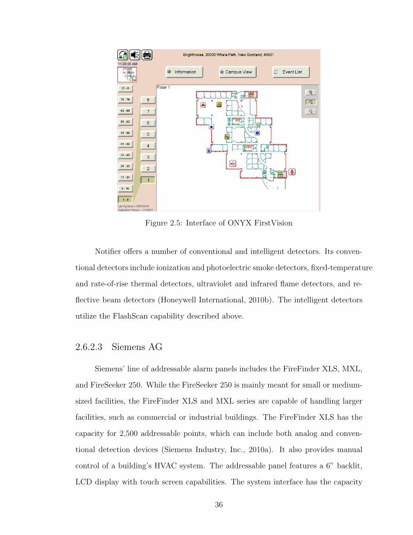
Figure 2.5: Interface of ONYX FirstVision
Notifier offers a number of conventional and intelligent detectors. Its conven-
tional detectors include ionization and photoelectric smoke detectors, fixed-temperature
and rate-of-rise thermal detectors, ultraviolet and infrared flame detectors, and re-
flective beam detectors (Honeywell International, 2010b). The intelligent detectors
utilize the FlashScan capability described above.
2.6.2.3 Siemens AG
Siemens’ line of addressable alarm panels includes the FireFinder XLS, MXL,
and FireSeeker 250. While the FireSeeker 250 is mainly meant for small or medium-
sized facilities, the FireFinder XLS and MXL series are capable of handling larger
facilities, such as commercial or industrial buildings. The FireFinder XLS has the
capacity for 2,500 addressable points, which can include both analog and conven-
tional detection devices (Siemens Industry, Inc., 2010a). It also provides manual
control of a building’s HVAC system. The addressable panel features a 6” backlit,
LCD display with touch screen capabilities. The system interface has the capacity
36

for hundreds of large-font text characters, hazmat icons, NFPA fire safety symbols,
and graphic maps, and provides access to a history log that is capable of hold-
ing 5,000 events. This series also includes a remote printer module that provides
an output port that, when configured, can be used to communicate with external
systems.
In the MXL series, the MXL is an analog fire protection system and is one
of the acceptable fire alarm systems on the University of Maryland campus. It
is capable of handling more than 2,000 intelligent input-devices and is capable of
monitoring security devices (Siemens Industry, Inc., 2006). Some of its features are
not as sophisticated as those of the XLS. The panel only includes an 80-character
backlit alphanumeric display and an 800-event history log. The MXLV has simi-
lar capabilities as the MXL, but also includes a voice evacuation system (Siemens
Industry, Inc., 2005). Both the XLS and MXL can be combined into a network of
other XLS and MXL systems that can be monitored and controlled using a network
color-graphics command center.
Siemens also provides three types of detection devices: conventional, intelli-
gent, and specialized. The conventional detection devices are similar to those of
SimplexGrinnell and Honeywell. The thermal detectors can be rate-of-rise, fixed-
temperature, a combination of the two, or Detect-A-Fire (Siemens Industry, Inc.,
2002). Detect-A-Fire thermal detectors are rate-compensating and can accurately
detect the surrounding air temperature regardless of the fire growth rate.
The intelligent detectors include photoelectric detectors, ionization detectors,
FirePrint detectors, and thermal detectors. These differ from their conventional
counterparts in that each contains a microprocessor that allows more complex de-
tection, error-checking, and supervision algorithms to be remotely programmed into
the detectors (Siemens Industry, Inc., 2010b). This allows the detectors to dis-
tinguish between false alarms and actual fire hazards. The FirePrint detector has
37
photoelectric and thermal sensing capabilities and can use fire hazard profiles pro-
grammed from the control panel to compare data.
Specialized detectors include a VESDA air sampling system, the Series 3/X3
air duct detector, and linear beam smoke detector. The VESDA LaserPLUS de-
tector draws air from a network of air sampling pipes, with each pipe containing a
sensor that detects changes in airflow (Siemens Industry, Inc., 2003). Before the air
reaches a laser light sources inside the VESDA detector, it passes through a dual-
stage air filtration system that filters dust from the air and prevents the inner cham-
ber from being contaminated. The VESDA LaserPlus detector can communicate
with other VESDA detectors through a communications protocol called VESDAnet.
It is separate from NOTI-FIRE-NET. The Series 3/X3 air duct detector operates
independently, while the linear beam smoke detector is compatible with the MXL
series of fire alarm control panels.
2.6.3 Other Relevant Technology
2.6.3.1 Keltron
The University of Maryland Facilities Management recently installed a Keltron
Life Safety Event Management System to monitor the more than 200 fire alarm
systems located on its campus (Robinson, 2009). For decades, the University had
been using its HVAC system for this purpose, and this presented a number of issues.
First, only sixty percent of the campus alarm systems could be monitored using the
HVAC systems, forcing the management to rely on people to call in whenever an
alarm was set off. Second, the HVAC system was not designed to handle the variety
of brands and models that are represented on the campus. This greatly limited the
amount of information available to the technicians and firefighters, all of whom had
to defer to the building’s control panel for further details. Third, HVAC systems are
38
not held to the same strict codes of fire alarm systems, leaving the University with
major flaws in the communication pathways between the detector and the central
monitoring system.
The solution to these issues was the installation of the Keltron Active Net-
work Radio System (Corporation, 2009). It utilizes wireless transceivers with 8
programmable inputs that allow for two-way transmission between the detector and
the central monitoring location. With the Keltron DataTap, transceivers can take
point-specific information from fire alarm control panels and relay it through the
network. This device is connected to the control panel’s RS-232 port and is com-
patible with the four manufacturers discussed above.
Keltron also offers Ethernet networking systems that have similar capabili-
ties as those of its radio system. The company also features its fire and security
alarm monitoring systems called the DMP703 (Corporation, 2008). The DMP703
can handle 20,000 direct connect inputs for continuous supervised monitoring and
includes a touch screen. The system can also interface with other fire alarm control
panels via the RS-232 ports.
2.7 Current Firefighter Technology
In addition to the technology of building sensor systems, EFRs use, or are
beginning to use, a variety of technologies for preplanning, firefighter locators and
vital signs indicators. These technologies can be applied to EMS and hazmat inci-
dents as well as fires. However, most of the technology is aimed at firefighters. In
an emergency situation, knowing the hazards of the building and the location and
health of firefighters is essential to a successful resolution to the event.
39

2.7.1 Pre-planning Software
Pre-planning is an essential tool for firefighters. Pre-plans locate fire hydrants,
stairwells, hazardous materials in a building, and fire alarm control panels. In
addition, pre-plans make note of building construction in terms of flammability,
known difficulties in access, and surrounding traffic patterns (NFPA 1620: Standard
for pre-incident planning , 2010). While pre-planning has traditionally been done on
paper, several companies provide software to aid in creating pre-plans. The CAD
Zone, Iron Compass, RealView, and FDM are some of the producers of pre-planning
software. Each pre-planning aid aims to comply with NFPA 1620.
The CAD Zone was one of the first companies to begin producing software
for pre-planning purposes. Their Fire Zone product helps fire service personnel
draw site plans and add pertinent pre-incident planning information. It uses simple
drawing tools to construct the floor plans, as well as using pre-made symbols to
represent stairs, hydrants, and hazards (Zone, 2010a). In order to make the pre-
plans accessible on the scene of the incident, The CAD Zone also sells First Look
Pro, a mobile pre-plan organizer. It is designed to be used on mobile computers
and even touch-screen computers. It uses a search function to find addresses and
displays the information input into Fire Zone. It also includes a mobile mapping
function to show the fire service vehicle’s progress toward the location of the event
through global positioning system (GPS) tracking (Zone, 2010b).
The next producer of pre-incident planning technology is Iron Compass, a
company known for making maps. Their OnScene Xplorer product also uses a search
function to find addresses or intersections, with “spell-right” technology ensuring
proper street name entry. Depending on the zoom of the image, different information
is displayed to simplify read-out. In addition GPS technology can be used to find
fire hydrants and give precise coordinates to MedEvac helicopters. It also allows
for space to note important information such as occupancy, shut-off valve locations,
40
hazardous materials, and fire suppression systems. Rather than having a separate
mobile program, OnScene Xplorer can be used to create and view pre-plans en route
(Compass, 2010).
RealView produces Command Scope, their mobile pre-planning software, avail-
able as a yearly subscription. All the pre-planning data is synchronized across a
department through a RealView server. Command Scope allows for both com-
mercial and residential pre-plans by asking residents to submit their own pre-plan
information online. Like the other softwares, Command Scope shows building site
information, hazmat details, and geographic information system (GIS) maps (LLC,
2010).
Another producer of pre-planning software is FDM. FDM produces records
management system (RMS) modules for a variety of applications including hydrant
tracking, personnel management, maintenance records, training details, and prop-
erty information. The properties module includes records from prior incidents,
permit information and inspection results. The properties module also includes
information on occupancy, building construction, hazards, important contacts and
built-in safety features. All of FDM’s modules are fully customizable, allow for image
viewing and connect with the fire department’s CAD program so that dispatchers
can have access to information and building plans (FDM, 2010).
2.7.2 Locator and Vital Sign Indicator Technology
Tracking firefighters within an incident allows the incident commander to be
certain that all firefighters are in their intended locations to better combat the fire as
well as avoid injury. There are several ways that firefighters can be tracked within a
building. Pedometry uses calibrated step lengths to estimate distance and direction,
as well as vertical movement. It counts steps to provide the relative location and
display the estimated path over the floor plan. In ad hoc self-forming networks,
41
also known as mesh networks, radio networks form that uses the time of signal
from other users to track location and direction. Like pedometry, it also shows a
relative location and can be overlaid on the floor plan. If the incident commander
can be linked in, he can see the locations of all the firefighters. Unfortunately,
linkage from the inside of the building to the outside can be difficult with ad hoc
networks due to the need for a grid layout in order to operate correctly. Another
method is through triangulation. Using transmitters with known coordinates, such
as those in fire service vehicles outside the building, the locations are pinpointed
and can be displayed on the floor plan. Triangulation can successfully transmit
through different materials and the incident commander can see the entire team.
Other technology used to track firefighters includes ultra wideband (UWB) and
radio-frequency identification (RFID) technologies (Bryner, 2008).
Scott Health and Safety produces the Pak-Tracker, a firefighter-locating device.
The Pak-Tracker operates on a directional 2.4 GHz radio frequency. The handheld
monitor can connect with up to thirty-six individual units. It is designed to be
operated with gloves on and weighs only 2.2 lbs. It can be used alone or incorporated
into a self-contained breathing apparatus (SCBA) system. If the system does not
detect movement for a period of time, it goes into full transmission mode so that
other firefighters can find the immobile firefighter. When using the handheld module,
audio and visual tools help locate the firefighter (Health & Safety, 2010).
Harris Corp’s GR-100 firefighter tracker uses a SCBA-mounted transmitter
and a radio network at 700 and 800 MHz frequencies to track firefighters. The data
is then displayed on a graphic user interface (GUI) so that an incident commander
can track the firefighters in 3D, updated every few seconds. The system also uses
accuracy-enhancing algorithms, inertial information, and GPS tracking. In order to
address some challenging structures for fire departments, Harris aimed the product
at single-family residences, strip malls, and small office buildings. The GR-100
42
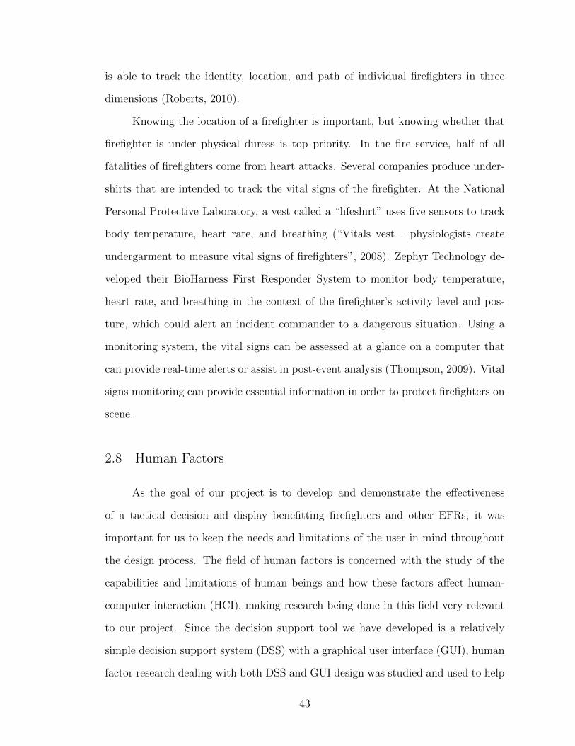
is able to track the identity, location, and path of individual firefighters in three
dimensions (Roberts, 2010).
Knowing the location of a firefighter is important, but knowing whether that
firefighter is under physical duress is top priority. In the fire service, half of all
fatalities of firefighters come from heart attacks. Several companies produce under-
shirts that are intended to track the vital signs of the firefighter. At the National
Personal Protective Laboratory, a vest called a “lifeshirt” uses five sensors to track
body temperature, heart rate, and breathing (“Vitals vest – physiologists create
undergarment to measure vital signs of firefighters”, 2008). Zephyr Technology de-
veloped their BioHarness First Responder System to monitor body temperature,
heart rate, and breathing in the context of the firefighter’s activity level and pos-
ture, which could alert an incident commander to a dangerous situation. Using a
monitoring system, the vital signs can be assessed at a glance on a computer that
can provide real-time alerts or assist in post-event analysis (Thompson, 2009). Vital
signs monitoring can provide essential information in order to protect firefighters on
scene.
2.8 Human Factors
As the goal of our project is to develop and demonstrate the effectiveness
of a tactical decision aid display benefitting firefighters and other EFRs, it was
important for us to keep the needs and limitations of the user in mind throughout
the design process. The field of human factors is concerned with the study of the
capabilities and limitations of human beings and how these factors affect human-
computer interaction (HCI), making research being done in this field very relevant
to our project. Since the decision support tool we have developed is a relatively
simple decision support system (DSS) with a graphical user interface (GUI), human
factor research dealing with both DSS and GUI design was studied and used to help
43

guide our design choices.
2.8.1 Decision Support Systems (DSS)
We define decision support systems to be those computer systems dedicated to
aiding the decision-making process of the user by providing him or her with informa-
tion gained through analysis of available data. Research concerning DSS designed to
support emergency response is particularly relevant to our project. Unfortunately,
literature dealing with emergency DSS is lacking when compared to the research that
has been conducted concerning DSS with more conventional, corporate applications.
It should be noted, however, that the body of research on emergency DSS has been
steadily growing in recent years (Dai, Wang, & Yang, 1994). Dai et al. (1994) studied
the design and development of computer support systems intended to aid emergency
decision-making. Their paper addresses three main issues: the differences between
emergency decision-making and what the authors call conventional decision-making,
the kinds of aid DSS are capable of providing for emergency decision-making, and
the specific requirements that should be considered in the design and development
of emergency DSS. According to Dai et al., emergency decision-making problems
differ from conventional decision-making problems in the following five ways:
1. Attributes of an emergency-decision making problem are often uncertain.
2. Environmental factors are often changing rapidly in emergency scenarios.
3. Emergency decisions are often time-dependent and are often made with in-complete or inexact information.
4. Usually only one or two goals are important in an emergency situation.
5. Even the soundest decision may involve substantial risks when faced with anemergency scenario.
(Dai et al., 1994)
44
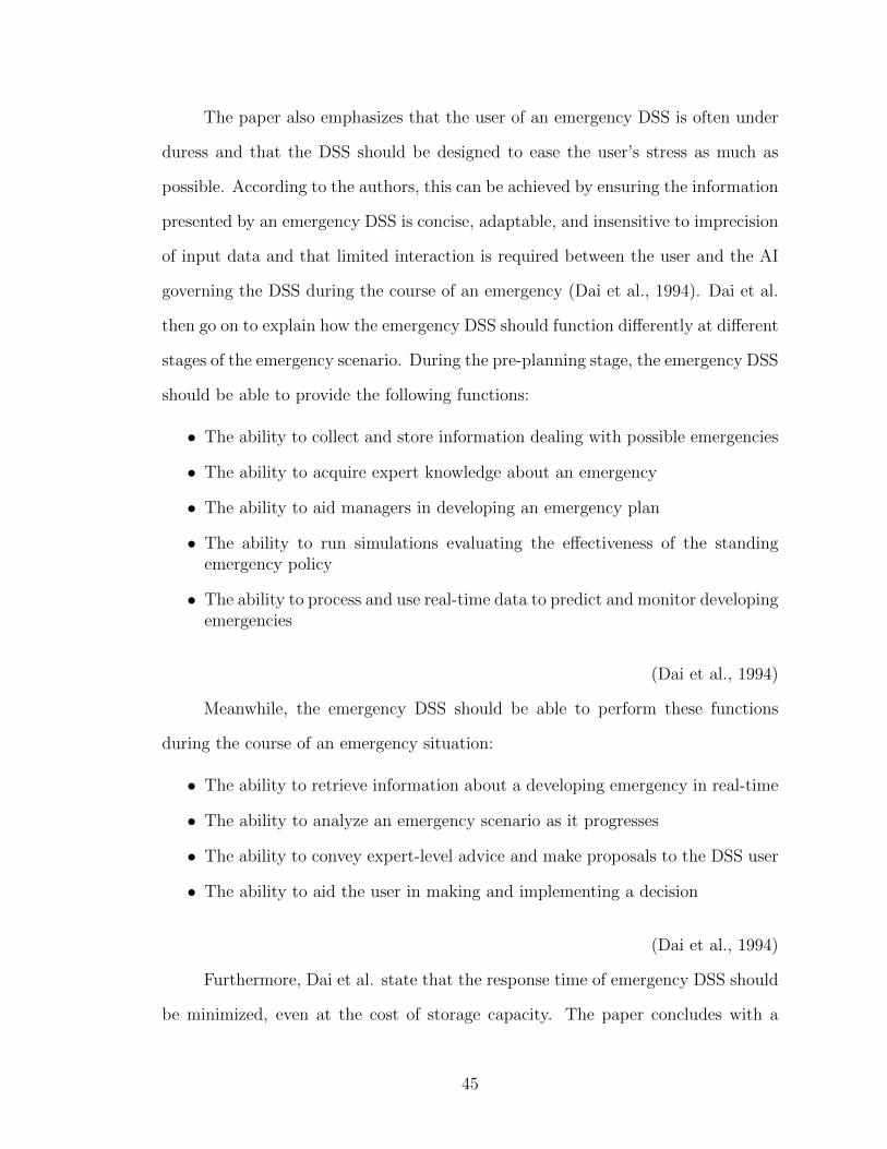
The paper also emphasizes that the user of an emergency DSS is often under
duress and that the DSS should be designed to ease the user’s stress as much as
possible. According to the authors, this can be achieved by ensuring the information
presented by an emergency DSS is concise, adaptable, and insensitive to imprecision
of input data and that limited interaction is required between the user and the AI
governing the DSS during the course of an emergency (Dai et al., 1994). Dai et al.
then go on to explain how the emergency DSS should function differently at different
stages of the emergency scenario. During the pre-planning stage, the emergency DSS
should be able to provide the following functions:
• The ability to collect and store information dealing with possible emergencies
• The ability to acquire expert knowledge about an emergency
• The ability to aid managers in developing an emergency plan
• The ability to run simulations evaluating the effectiveness of the standingemergency policy
• The ability to process and use real-time data to predict and monitor developingemergencies
(Dai et al., 1994)
Meanwhile, the emergency DSS should be able to perform these functions
during the course of an emergency situation:
• The ability to retrieve information about a developing emergency in real-time
• The ability to analyze an emergency scenario as it progresses
• The ability to convey expert-level advice and make proposals to the DSS user
• The ability to aid the user in making and implementing a decision
(Dai et al., 1994)
Furthermore, Dai et al. state that the response time of emergency DSS should
be minimized, even at the cost of storage capacity. The paper concludes with a
45
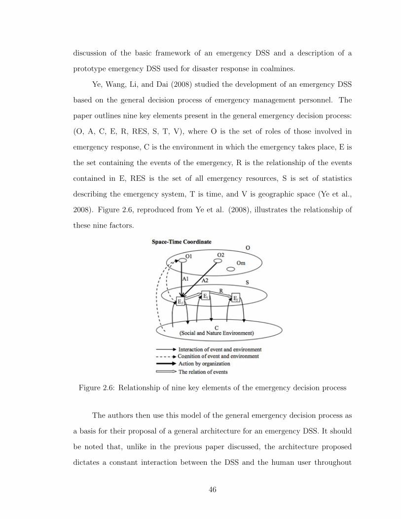
discussion of the basic framework of an emergency DSS and a description of a
prototype emergency DSS used for disaster response in coalmines.
Ye, Wang, Li, and Dai (2008) studied the development of an emergency DSS
based on the general decision process of emergency management personnel. The
paper outlines nine key elements present in the general emergency decision process:
(O, A, C, E, R, RES, S, T, V), where O is the set of roles of those involved in
emergency response, C is the environment in which the emergency takes place, E is
the set containing the events of the emergency, R is the relationship of the events
contained in E, RES is the set of all emergency resources, S is set of statistics
describing the emergency system, T is time, and V is geographic space (Ye et al.,
2008). Figure 2.6, reproduced from Ye et al. (2008), illustrates the relationship of
these nine factors.
Figure 2.6: Relationship of nine key elements of the emergency decision process
The authors then use this model of the general emergency decision process as
a basis for their proposal of a general architecture for an emergency DSS. It should
be noted that, unlike in the previous paper discussed, the architecture proposed
dictates a constant interaction between the DSS and the human user throughout
46

the emergency scenario.
Drury, Klein, Pfaff, and More (2009) studied DSS that utilize simulations
to predict how a given decision will affect the course of an emergency situation.
A cost metric was developed to compare a decision to its alternatives. This cost
comparison was visually conveyed to the user through the display of box-and-whisker
plots. To assess the usefulness of this developed DSS, a test was designed where two
groups had to determine the number of emergency-response vehicles to dispatch to a
developing emergency situation. While both groups were given a textual description
the emergency scenario, only one group was given access to the developed DSS. It
was found that the DSS group was able to make decisions closer to the normatively
correct decision. Furthermore, the DSS group reported a higher degree of confidence
in their decisions and rated the amount of decision support they received higher than
the control group.
While not focusing on emergency DSS specifically, other human factors re-
search concerning DSS contain conclusions relevant to our project. Research dealing
with DSS designed to aid command decisions is especially relevant, as the target
user of our tactical decision aid display is the incident commander directing an
emergency response effort. Breton, Paradis, and Roy (2002) studied the work be-
ing done at the Defence R & D Canada - Valcartier toward developing a command
and control DSS design tool called CODSI (Command Decision Support Interface).
CODSI is used to evaluate and validate design concepts from both a human factors
perspective and an operational perspective. To illustrate the effectiveness of CODSI,
the design of a tactical DSS intended for naval threat-assessment applications was
studied. Through this study, CODSI was shown to accurately model and assess
human factors considerations of DSS with command and control applications.
Another facet of DSS research relevant to our project concerns the display
of uncertain information. Bisantz, Marsiglio, and Munch (2005) conducted four
47
studies regarding the display of probabilistic information. The first three studies
dealt with user performance of stock purchase tasks where information regarding
the profitability of a given stock was probabilistic. Two aspects of the display were
varied in these studies: the display format and the specificity level of probabilistic
information. From these studies it was concluded that while performance did not
vary with display format, increased specificity improved performance. The fourth
study had participants create membership functions that corresponded to three
distinct display formats. From this study it was found that users can successfully
interpret probabilistic information displayed in a non-numeric manner and use this
information to make effective decisions.
A good portion of the human factors research being conducted on DSS deals
with the design of so-called “intelligent” systems, systems with a high degree of au-
tomation. Guerlain, Brown, and Mastrangelo (2000) studied characteristics that are
common to three intelligent DSS shown to be successful in practice: the Antibody
Identification Assistant (AIDA), the Regional Crime Analysis Program (RECAP),
and the River Flooding Forecasting System. Six attributes representative of suc-
cessful intelligent DSS were determined from this study and are given below:
1. Interactivity - the system is able work well with both human users and databases.Users are given a wide variety of possibilities instead of a single “optimal” de-cision.
2. Event and Change Detection - the system is able to effectively communicatestatus changes and important events.
3. Representation aiding - the system is able to convey information in an infor-mative yet human-like way.
4. Error Detection and Recovery - the system is able to check for typical reasoningerrors made by users. The system is also able to identify situations that arebeyond its own capabilities.
5. Information out of Data - The system is able to extract information from largedata sets and provide the user tools for dealing with smaller data sets, outliers,and possible sources of error.
48
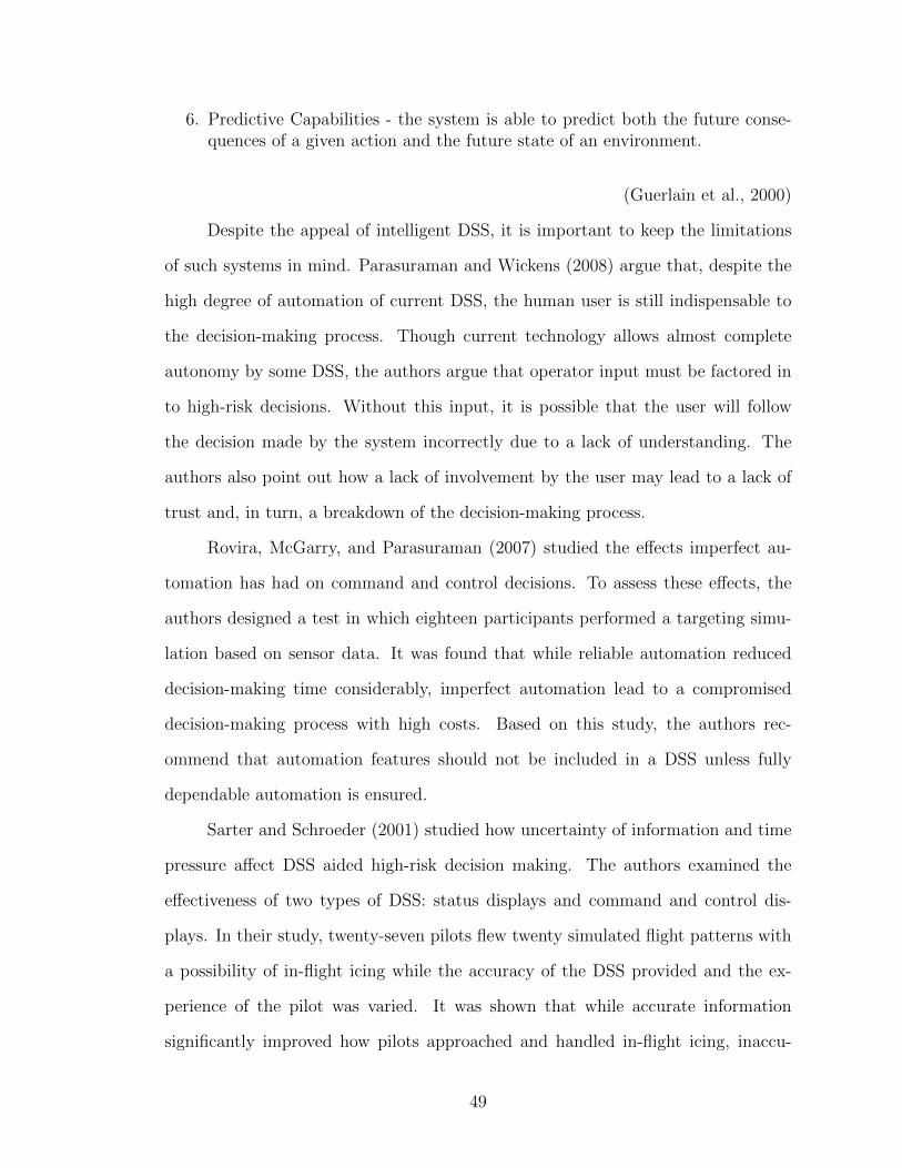
6. Predictive Capabilities - the system is able to predict both the future conse-quences of a given action and the future state of an environment.
(Guerlain et al., 2000)
Despite the appeal of intelligent DSS, it is important to keep the limitations
of such systems in mind. Parasuraman and Wickens (2008) argue that, despite the
high degree of automation of current DSS, the human user is still indispensable to
the decision-making process. Though current technology allows almost complete
autonomy by some DSS, the authors argue that operator input must be factored in
to high-risk decisions. Without this input, it is possible that the user will follow
the decision made by the system incorrectly due to a lack of understanding. The
authors also point out how a lack of involvement by the user may lead to a lack of
trust and, in turn, a breakdown of the decision-making process.
Rovira, McGarry, and Parasuraman (2007) studied the effects imperfect au-
tomation has had on command and control decisions. To assess these effects, the
authors designed a test in which eighteen participants performed a targeting simu-
lation based on sensor data. It was found that while reliable automation reduced
decision-making time considerably, imperfect automation lead to a compromised
decision-making process with high costs. Based on this study, the authors rec-
ommend that automation features should not be included in a DSS unless fully
dependable automation is ensured.
Sarter and Schroeder (2001) studied how uncertainty of information and time
pressure affect DSS aided high-risk decision making. The authors examined the
effectiveness of two types of DSS: status displays and command and control dis-
plays. In their study, twenty-seven pilots flew twenty simulated flight patterns with
a possibility of in-flight icing while the accuracy of the DSS provided and the ex-
perience of the pilot was varied. It was shown that while accurate information
significantly improved how pilots approached and handled in-flight icing, inaccu-
49
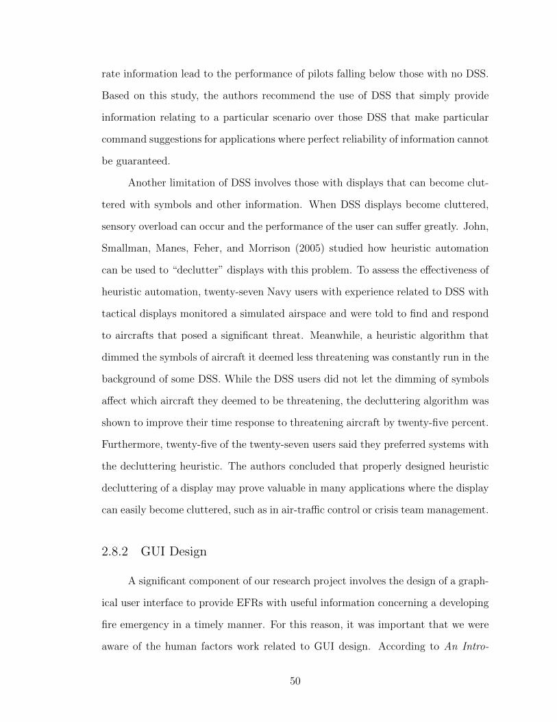
rate information lead to the performance of pilots falling below those with no DSS.
Based on this study, the authors recommend the use of DSS that simply provide
information relating to a particular scenario over those DSS that make particular
command suggestions for applications where perfect reliability of information cannot
be guaranteed.
Another limitation of DSS involves those with displays that can become clut-
tered with symbols and other information. When DSS displays become cluttered,
sensory overload can occur and the performance of the user can suffer greatly. John,
Smallman, Manes, Feher, and Morrison (2005) studied how heuristic automation
can be used to “declutter” displays with this problem. To assess the effectiveness of
heuristic automation, twenty-seven Navy users with experience related to DSS with
tactical displays monitored a simulated airspace and were told to find and respond
to aircrafts that posed a significant threat. Meanwhile, a heuristic algorithm that
dimmed the symbols of aircraft it deemed less threatening was constantly run in the
background of some DSS. While the DSS users did not let the dimming of symbols
affect which aircraft they deemed to be threatening, the decluttering algorithm was
shown to improve their time response to threatening aircraft by twenty-five percent.
Furthermore, twenty-five of the twenty-seven users said they preferred systems with
the decluttering heuristic. The authors concluded that properly designed heuristic
decluttering of a display may prove valuable in many applications where the display
can easily become cluttered, such as in air-traffic control or crisis team management.
2.8.2 GUI Design
A significant component of our research project involves the design of a graph-
ical user interface to provide EFRs with useful information concerning a developing
fire emergency in a timely manner. For this reason, it was important that we were
aware of the human factors work related to GUI design. According to An Intro-
50

duction to Human Factors Engineering (2004) by Wickens et al., there are thirteen
principles of display design to consider when creating an effective GUI. These thir-
teen principles are as follows:
1. Make displays legible (or audible): The characters or objects being displayedmust be discernible.
2. Avoid absolute judgment: Users should not be required to judge the level ofa variable on the basis of a single sensory variable.
3. Top-down processing: People will perceive and interpret signals based on priorexperience.
4. Redundancy gain: The more times a message is presented, the more likely itis to be correctly interpreted.
5. Discriminability: Similar appearing signals will most likely be confused.
6. Principle of pictorial realism: Symbols employed should look like the objector element that it represents.
7. Principle of the moving part: The moving elements should move consistentlywith the user’s expectations.
8. Minimizing information access costs: Keep frequently accessed sources in alocation such that the cost of traveling between them is small.
9. Proximity compatibility principle: Sometimes two or more separate sourcesof information are required to complete a given task and must be mentallyintegrated.
10. Principle of multiple resources: Information should be divided across resourcesto allow easier processing by the user.
11. Principle of predictive aiding: A display that predicts future events will usuallyenhance human performance.
12. Replace memory with visual information: knowledge in the world: Place spe-cific cues in the task environment to remind the user what needs to be done.
13. Principle of consistency: Symbols and other design elements should be consis-tent with other displays the user may be using.
(Wickens, Lee, & Liu, 1997)
51
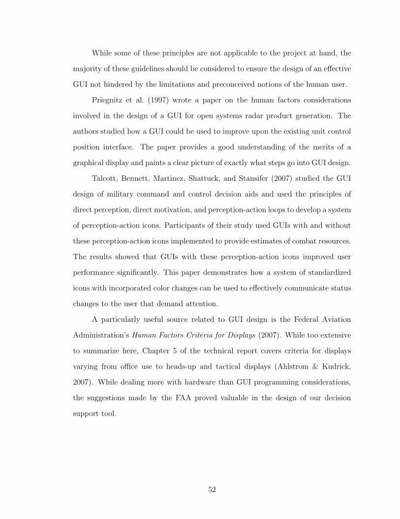
While some of these principles are not applicable to the project at hand, the
majority of these guidelines should be considered to ensure the design of an effective
GUI not hindered by the limitations and preconceived notions of the human user.
Priegnitz et al. (1997) wrote a paper on the human factors considerations
involved in the design of a GUI for open systems radar product generation. The
authors studied how a GUI could be used to improve upon the existing unit control
position interface. The paper provides a good understanding of the merits of a
graphical display and paints a clear picture of exactly what steps go into GUI design.
Talcott, Bennett, Martinez, Shattuck, and Stansifer (2007) studied the GUI
design of military command and control decision aids and used the principles of
direct perception, direct motivation, and perception-action loops to develop a system
of perception-action icons. Participants of their study used GUIs with and without
these perception-action icons implemented to provide estimates of combat resources.
The results showed that GUIs with these perception-action icons improved user
performance significantly. This paper demonstrates how a system of standardized
icons with incorporated color changes can be used to effectively communicate status
changes to the user that demand attention.
A particularly useful source related to GUI design is the Federal Aviation
Administration’s Human Factors Criteria for Displays (2007). While too extensive
to summarize here, Chapter 5 of the technical report covers criteria for displays
varying from office use to heads-up and tactical displays (Ahlstrom & Kudrick,
2007). While dealing more with hardware than GUI programming considerations,
the suggestions made by the FAA proved valuable in the design of our decision
support tool.
52
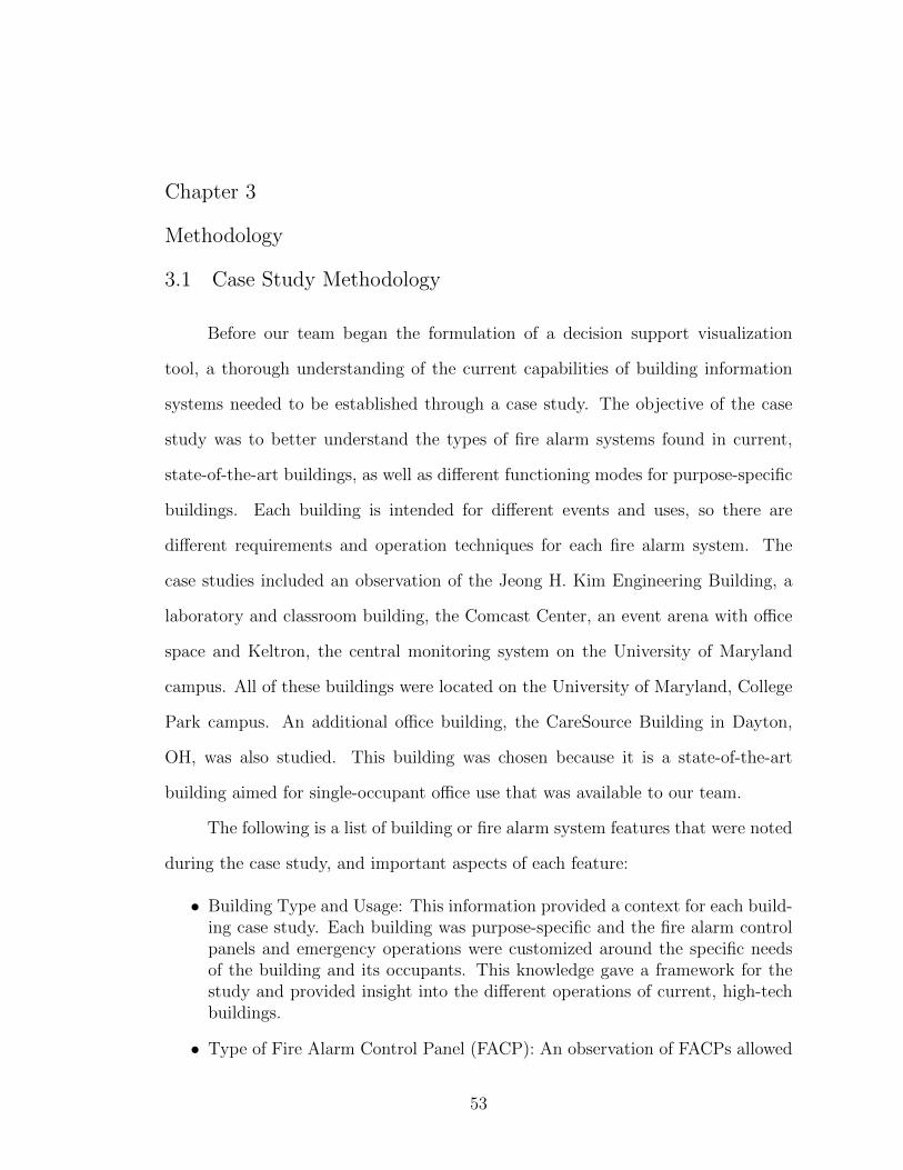
Chapter 3
Methodology
3.1 Case Study Methodology
Before our team began the formulation of a decision support visualization
tool, a thorough understanding of the current capabilities of building information
systems needed to be established through a case study. The objective of the case
study was to better understand the types of fire alarm systems found in current,
state-of-the-art buildings, as well as different functioning modes for purpose-specific
buildings. Each building is intended for different events and uses, so there are
different requirements and operation techniques for each fire alarm system. The
case studies included an observation of the Jeong H. Kim Engineering Building, a
laboratory and classroom building, the Comcast Center, an event arena with office
space and Keltron, the central monitoring system on the University of Maryland
campus. All of these buildings were located on the University of Maryland, College
Park campus. An additional office building, the CareSource Building in Dayton,
OH, was also studied. This building was chosen because it is a state-of-the-art
building aimed for single-occupant office use that was available to our team.
The following is a list of building or fire alarm system features that were noted
during the case study, and important aspects of each feature:
• Building Type and Usage: This information provided a context for each build-ing case study. Each building was purpose-specific and the fire alarm controlpanels and emergency operations were customized around the specific needsof the building and its occupants. This knowledge gave a framework for thestudy and provided insight into the different operations of current, high-techbuildings.
• Type of Fire Alarm Control Panel (FACP): An observation of FACPs allowed
53

Team FFA to understand what types of panels are currently used in state-of-the-art buildings. These findings were used to direct our efforts in requestingdonations of equipment. It was necessary to obtain commonly used panels forfurther testing.
• Location of FACP and Other Control Panels: To understand the current op-erations of firefighters during emergency situations, it was necessary to notetypical locations of control panels in buildings. The current locations empha-sized a need for external access to FACP information.
• Current Floor Plans or Maps: An examination of the floor plans and mapsprovided insight into current systems. Current floor plans and maps found inthese buildings were simplistic and vague, indicating a possibility for improve-ment to the information provided on floor plans.
• Sensor Numbering and Addressability: Many current sensors are point-addressable.Sensor location data were pinpointed as possibly useful yet underutilized as-pects of current technology.
• Specialty Sensors: Chemical sensors, high-tech smoke detection systems, pres-surized stairwells and elevators were all noted as items of particular interest.
3.2 System Design
3.2.1 Assessing EFR Needs
In order to adequately demonstrate how a decision support visualization tool
can effectively utilize, contextualize, and present building sensor data, our team saw
it necessary to construct a prototype decision support tool. In accordance with most
established design methodologies, we began our prototype design by considering the
needs and limitations of the end users, namely firefighters and other EFRs. In 2004,
NIST held a workshop to identify and inventory the information needs of EFRs
during the course of an emergency situation (Jones et al., 2005). Our team used
the results of this workshop as a starting point toward determining what types of
information should be included in and conveyed by our prototype visualization tool.
Appendix C of the technical report “Workshop to Define Information Needed
by Emergency Responders during Building Emergencies” contains several lists of
54

the kinds of information that firefighters would like to know both en route to a
fire emergency and on the scene of the fire (Jones et al., 2005), as discussed in
Section 2.4 of this thesis. These lists are quite exhaustive, so our team felt it was
important to prioritize the items requested and include only the most important
information in our prototype. After consolidating all the information requested
by EFRs during the course of the workshop into two lists (static and dynamic
information), we categorized each item requested as either high priority (information
essential to understanding the nature and progression of a fire emergency that must
be included if available), medium priority (potentially useful information that is
either not entirely necessary or would be hard to integrate into our prototype), or
low priority (information that is excessive, unnecessary, or not currently available).
In order to avoid clutter, we decided to include only the information classified as
high priority. The resulting list of static information derived from the workshop
includes:
• Building style (e.g., one story, two story, n-story, auditorium, sublevels, etc.)
• Building construction (e.g., type I, II, III, IV or V; fire resistive, noncom-bustible or limited combustible, ordinary, heavy timber, or wood frame)
• Presence and Location of Hazardous materials (e.g., above ground propanetank, gas lines, chemicals, etc.)
• Location of fire department hookups for sprinkler systems and/or standpipes
• Location of staging areas and entrances and exits to buildings
• Location of doors, windows, stairwell risers, fire walls (with ratings and areaseparation), roof access, and fire sensors
• Location of fire alarm panels and remote annunciator panels
• Location of utility shutoffs
• Location of building system controls (e.g., HVAC, smoke control, etc.), areasof effect, and special operating systems
• Location of evacuation quality elevators, floors served, and location of elevatoroverrides and how to control
55
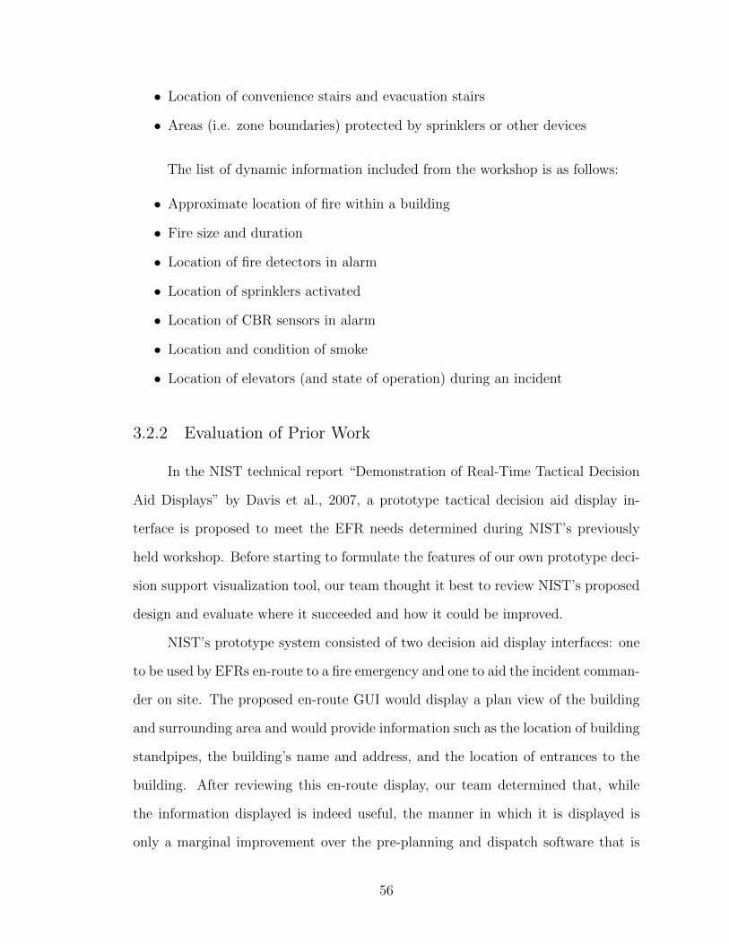
• Location of convenience stairs and evacuation stairs
• Areas (i.e. zone boundaries) protected by sprinklers or other devices
The list of dynamic information included from the workshop is as follows:
• Approximate location of fire within a building
• Fire size and duration
• Location of fire detectors in alarm
• Location of sprinklers activated
• Location of CBR sensors in alarm
• Location and condition of smoke
• Location of elevators (and state of operation) during an incident
3.2.2 Evaluation of Prior Work
In the NIST technical report “Demonstration of Real-Time Tactical Decision
Aid Displays” by Davis et al., 2007, a prototype tactical decision aid display in-
terface is proposed to meet the EFR needs determined during NIST’s previously
held workshop. Before starting to formulate the features of our own prototype deci-
sion support visualization tool, our team thought it best to review NIST’s proposed
design and evaluate where it succeeded and how it could be improved.
NIST’s prototype system consisted of two decision aid display interfaces: one
to be used by EFRs en-route to a fire emergency and one to aid the incident comman-
der on site. The proposed en-route GUI would display a plan view of the building
and surrounding area and would provide information such as the location of building
standpipes, the building’s name and address, and the location of entrances to the
building. After reviewing this en-route display, our team determined that, while
the information displayed is indeed useful, the manner in which it is displayed is
only a marginal improvement over the pre-planning and dispatch software that is
56

already in use by many fire departments. For this reason, we decided to devote our
attention solely to the proposed on-site interface.
The top of NIST’s on-site display (reproduced in Figure 3.1) is populated with
several buttons that allow the user to choose which kinds of information should be
overlaid on a floor plan of the building. The types of information that can be
called by each button are as follows: security (e.g., information from security sen-
sors), elevator (e.g., number and location of elevators), fire-fighting equipment (e.g.,
location of fire extinguishers), utilities (e.g., location of utility shutoffs), building
generator (i.e., location of building generator), fire walls (i.e., location and ratings
of fire walls), standpipes (i.e., location of interior fire department standpipe connec-
tions), hazardous materials (e.g., location of hazardous materials within the build-
ing), building hazards (i.e. information of potential hazards to EFRs), and valuable
materials (i.e., location of extremely valuable materials) (Davis et al., 2007). When
a button is selected, the associated information is symbolically displayed on the floor
plan in real-time. Next to the building’s floor plan are buttons that allow the user
to zoom in and out, pan, and reset the view to the default setting. There are also
buttons that allow the user to change floors. On the bottom of the display, three
buttons are present: the first displays the building information from the en-route
display, the second allows the user to view a log of the alarms and changing building
conditions, and the third displays a legend of the symbols used in the map overlay.
57
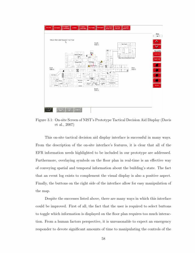
Figure 3.1: On-site Screen of NIST’s Prototype Tactical Decision Aid Display (Daviset al., 2007)
This on-site tactical decision aid display interface is successful in many ways.
From the description of the on-site interface’s features, it is clear that all of the
EFR information needs highlighted to be included in our prototype are addressed.
Furthermore, overlaying symbols on the floor plan in real-time is an effective way
of conveying spatial and temporal information about the building’s state. The fact
that an event log exists to complement the visual display is also a positive aspect.
Finally, the buttons on the right side of the interface allow for easy manipulation of
the map.
Despite the successes listed above, there are many ways in which this interface
could be improved. First of all, the fact that the user is required to select buttons
to toggle which information is displayed on the floor plan requires too much interac-
tion. From a human factors perspective, it is unreasonable to expect an emergency
responder to devote significant amounts of time to manipulating the controls of the
58

GUI while managing and reacting to a developing fire emergency (Dai et al., 1994).
However, the rationale behind the toggle buttons, to prevent information overload,
is clear and also a valid concern. Our team believes that a better way to avoid in-
formation overload would be to simply only display the information most pertinent
to conveying the status of the building. In addition, the fact that the event log and
the building pre-planning information are not displayed at all times on the interface
diminishes the effectiveness of the system. Our team also noted that a function that
allowed the user to replay the progression of the emergency would be very useful
as more details about a fire’s development will lead to more informed tactical de-
cisions. One last improvement would be graphically highlighting on which floors
the fire emergency is occurring to allow the user to quickly return to the floors of
greatest importance.
3.2.3 Design Goals and Basic Layout
After finishing our assessment of the NIST prototype tactical decision aid
display, considering the standard operating procedures of firefighters, and reviewing
the available literature on human factors, our team formulated our broad design
goals for our prototype system. These goals are as follows:
• Our decision support visualization tool should effectively achieve temporaland spatial contextualization of the information obtained from building sensorsystems.
• The interface should be intuitive to view and manipulate. This goal should beaccomplished by utilizing standardized symbols and familiar visuals.
• The display should be designed in such a way as to optimize the amount ofinformation that can be gleaned at a glance with particular emphasis placedon the most important data.
• The prototype’s design should be modular to allow future technology to beintegrated with relative ease.
59
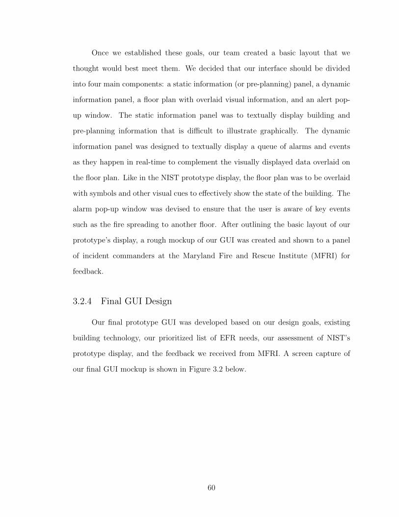
Once we established these goals, our team created a basic layout that we
thought would best meet them. We decided that our interface should be divided
into four main components: a static information (or pre-planning) panel, a dynamic
information panel, a floor plan with overlaid visual information, and an alert pop-
up window. The static information panel was to textually display building and
pre-planning information that is difficult to illustrate graphically. The dynamic
information panel was designed to textually display a queue of alarms and events
as they happen in real-time to complement the visually displayed data overlaid on
the floor plan. Like in the NIST prototype display, the floor plan was to be overlaid
with symbols and other visual cues to effectively show the state of the building. The
alarm pop-up window was devised to ensure that the user is aware of key events
such as the fire spreading to another floor. After outlining the basic layout of our
prototype’s display, a rough mockup of our GUI was created and shown to a panel
of incident commanders at the Maryland Fire and Rescue Institute (MFRI) for
feedback.
3.2.4 Final GUI Design
Our final prototype GUI was developed based on our design goals, existing
building technology, our prioritized list of EFR needs, our assessment of NIST’s
prototype display, and the feedback we received from MFRI. A screen capture of
our final GUI mockup is shown in Figure 3.2 below.
60
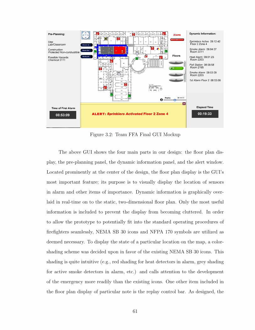
Figure 3.2: Team FFA Final GUI Mockup
The above GUI shows the four main parts in our design: the floor plan dis-
play, the pre-planning panel, the dynamic information panel, and the alert window.
Located prominently at the center of the design, the floor plan display is the GUI’s
most important feature; its purpose is to visually display the location of sensors
in alarm and other items of importance. Dynamic information is graphically over-
laid in real-time on to the static, two-dimensional floor plan. Only the most useful
information is included to prevent the display from becoming cluttered. In order
to allow the prototype to potentially fit into the standard operating procedures of
firefighters seamlessly, NEMA SB 30 icons and NFPA 170 symbols are utilized as
deemed necessary. To display the state of a particular location on the map, a color-
shading scheme was decided upon in favor of the existing NEMA SB 30 icons. This
shading is quite intuitive (e.g., red shading for heat detectors in alarm, grey shading
for active smoke detectors in alarm, etc.) and calls attention to the development
of the emergency more readily than the existing icons. One other item included in
the floor plan display of particular note is the replay control bar. As designed, the
61
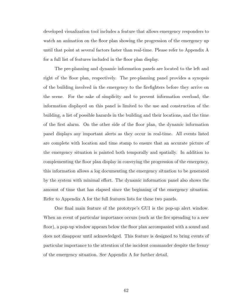
developed visualization tool includes a feature that allows emergency responders to
watch an animation on the floor plan showing the progression of the emergency up
until that point at several factors faster than real-time. Please refer to Appendix A
for a full list of features included in the floor plan display.
The pre-planning and dynamic information panels are located to the left and
right of the floor plan, respectively. The pre-planning panel provides a synopsis
of the building involved in the emergency to the firefighters before they arrive on
the scene. For the sake of simplicity and to prevent information overload, the
information displayed on this panel is limited to the use and construction of the
building, a list of possible hazards in the building and their locations, and the time
of the first alarm. On the other side of the floor plan, the dynamic information
panel displays any important alerts as they occur in real-time. All events listed
are complete with location and time stamp to ensure that an accurate picture of
the emergency situation is painted both temporally and spatially. In addition to
complementing the floor plan display in conveying the progression of the emergency,
this information allows a log documenting the emergency situation to be generated
by the system with minimal effort. The dynamic information panel also shows the
amount of time that has elapsed since the beginning of the emergency situation.
Refer to Appendix A for the full features lists for these two panels.
One final main feature of the prototype’s GUI is the pop-up alert window.
When an event of particular importance occurs (such as the fire spreading to a new
floor), a pop-up window appears below the floor plan accompanied with a sound and
does not disappear until acknowledged. This feature is designed to bring events of
particular importance to the attention of the incident commander despite the frenzy
of the emergency situation. See Appendix A for further detail.
62
3.3 Software Implementation
The task of implementing the software consisted of accessing and parsing sen-
sor data and displaying the information according to design specifications. Ac-
cordingly, the largest modules of the parser are 1) the data parser, 2) the building
representation and 3) the interface. The data parser processes the raw data ob-
tained from the sensor panel and updates the building representation. The building
representation organizes the received information to make it easy to find the state
of all sensors on a given floor at a given time. The interface displays the state of the
building at the floor and time selected by the user. The overarching modules can, in
turn, consist of a number of sub-modules. The desired behavior of the data parser
and the visualization interface is already well-defined: the parser needs to accept
the protocols used by building sensor systems, and the design of the visualization
interface was described in the previous section.
Throughout this implementation phase, we focused on developing software
that could be used to evaluate the effectiveness of the proposed approach to the
problem of data visualization. In the prototype, some functionality that would
be necessary for a full-featured application was omitted. We chose not to provide
solutions to previously solved problems, such as software distribution questions and
the networking necessary to make the obtained sensor data remotely available.
3.3.1 Software Design Choices
The visualization display interface was implemented in Java. The Object Ori-
ented paradigm employed in the programming environment Java was conducive to
a logical representation of building information: the building, floors, and sensors
were represented by separate object classes. More importantly, Java’s type poly-
morphism – a feature that enables a uniform interface to handle different complex
63
data types – simplified the task of writing modular code.
Since one of the goals of the project was to create a system that could interface
with building sensor systems regardless of type or manufacturer, the software was
designed to be able to receive input from a variety of different sources. For each
protocol used, a separate parser module is needed, but the other modules can be used
without modification. We wrote parsers for data received over RS-232 and BACnet,
since those were the two transmission methods used by the hardware donated to
our team. Additionally, we wrote a parser for Fire Dynamics Simulator output for
testing purposes.
3.3.2 Annotation Tool
Whereas the implementation of the data parser and the interface is simply
done according to specifications, the building representation required further con-
sideration. It was necessary to associate the sensor labels used by the annunciator
panels with their locations on the floor plan. Also, it was necessary to know the
areas of effect for each sensor in order to highlight the appropriate parts of the floor
plan when the sensors go into alarm. Unfortunately, this information is rarely stored
in a way that would allow us to directly use it in the software, so it is necessary to
input this information by hand for each building. Since this is a time-consuming and
error-prone task, we decided to develop an annotation tool, a separate application
to simplify the task of entering building information by hand.
The annotation tool uses an interface that is very similar to our decision sup-
port tool’s interface. The user marks the sensor location and area of effect directly
on the floor plan. Using a familiar graphical interface to enter information makes it
possible to quickly and accurately annotate the floor plan. The annotation tool also
allows for text-based information to be entered for any sensor, building floor or for
the entire building. The text information is organized into parameters and values
64
to allow comparison of different sensors or floors based on the values entered.
The variety of data that can be entered makes the annotation tool a robust
pre-planning utility that can be used for many different purposes. The annotation
is stored in XML format, which is well-defined, robust and can be handled by many
existing tools. We propose that the annotation tool or similar pre-planning software
be used to standardize the way that building information is stored and accessed.
3.4 Hardware Testing
3.4.1 Overview
The goal of the hardware testing was to demonstrate that the decision support
tool is capable of processing actual sensor inputs as well as display the information
accurately. We used mockups of fire sensor equipment donated to our team by
Honeywell and SimplexGrinnell to obtain these inputs.
The hardware setup consisted of two different FACPs, one Notifier NFS-640
and one Simplex4100U, both of which are approved for use in buildings on campus.
Each FACP was hooked up to the following sensors:
• 3 photoelectric smoke sensors
• 3 ionization smoke sensors
• 3 heat sensors
• 1 flow switch
• 1 tamper switch
• 1 manual pull station
The FACPs were in turn connected to a laptop. The laptop used to run the
decision support software had the following key specifications:
• Processor: Intel Pentium M, 1.73 GHz
65

• Harddrive: Fujitsu MHV2060AH ATA Device, 5400 RPM
• RAM: 1024 MB at 266 MHz
It is possible that due to the age of the parts, the specifications of the laptop
contributed to delay in the response time of the decision support tool.
Using the sensors available to each FACP, a floor plan was devised placing
each sensor on one of three floors. The floor plan itself, shown below, is a basic
hallway with three rooms, a door on the first floor and a stairwell leading up to each
floor.
Figure 3.3: A mockup floor plan for real lab hardware to simulate.
Using the devised sensor layout, the floor plan was then formatted for input
using our developed annotation tool. This annotation identified each sensor on the
floor plan and its approximate area of effect that will be visually displayed on the
system should the sensor go into alarm.
In order to use the hardware to simulate an emergency scenario, sensors were
manually triggered according to a pre-written plan of events. This pre-written plan,
66

provided in Appendix B, established an emergency scenario, identifying what sensors
go off at what time steps. By controlling the input to the sensors, the output of
the system can be analyzed to identify if the real sensor hardware will perform as
expected. For this experiment, it is expected that the system will accurately denote
which sensors are going off on a floor plan and that there will be little lag time (less
than ten seconds) between when a sensor goes into alarm and when it is displayed
as being in alarm by the prototype system.
3.4.2 Panel Output Protocols
The Simplex 4100U panel and the Notifier NFS-640 panel are significant be-
cause they both have BACnet gateways installed. The BACnet gateway allowed
for the output of each system to be standardized, so that sensor states from each
system are identical. BACnet transferred this data to the system over an Ethernet
cable through a network card on a computer.
The default settings on the BACnet card provided with the Simplex panel
were not configured to monitor analog values. The card was reprogrammed to
specifically monitor analog values of sensors over time. Heat sensors that measured
room temperature would then display their current readings in degrees Fahrenheit,
and smoke sensors would read their values on the obscuration of the air.
The output of the sensors via BACnet now become the input to the system. As
previously mentioned, BACnet is convenient because it is a standard protocol that
is installed on a variety of FACPs across several manufacturers in addition to Hon-
eywell and Simplex Grinnell. However, in the interest of thorough experimentation,
another communication protocol was used – RS-232. RS-232 is a well-established
way to transfer serial data from one device to the next. Virtually every FACP has
RS-232 output; serial data transfer is the primary method for communicating with
the printer. With very basic wiring, the printer data stream can be tapped and fed
67
into a computer’s serial data port or a USB port with a DB9 serial data adapter.
Because of the simplicity of serial data provides, and the ubiquity of RS-232 output
from FACPs, RS-232 was also explored as a method for taking the output of the
FACPs and making that the input for the decision support tool.
3.4.3 Hardware and Scenario Mockup
Each FACP in the mockup was hooked up to twelve different detectors and
modules in a Type A loop, meaning a single wire connected each sensor in a loop that
began and ended at the FACP. Each flow switch and tamper switch was connected
to manual toggle switches, allowing both the manual pull stations and the tamper
and flow switches to be instantly activated as necessary. Each photoelectric and
ion smoke sensor, as well as the heat sensors, was activated by applying a magnet
at a specific point near the LED light. The sensors triggered on application of the
magnet; however, there was a significant delay between the application of the magnet
and when the sensor actually went into alarm. It also appeared that the delay was
different from sensor to sensor. Brief experimentation was required to obtain the
average response time of each sensor to ensure reliable system input. Appendix C
outlines the testing procedure and results for this experimentation. Additionally, for
the Simplex 4100U panel, analog values were measured by the sensors. The specific
output from the FACPs includes: time of sensor alarm; what sensor on the loop
went into alarm, identified by its loop address; its custom ID (inputted specifically
to match with the system input); the alarm state of the sensor (supervisory warning,
a trouble signal, or in a fire alarm state); and what the analog value of the sensor is,
if it has one. In order to test for analog values (which magnet tests do not affect),
canned smoke was applied in specified bursts to each smoke sensor, and a heat gun
was placed beneath each heat sensor in order to trigger the sensor and measure
changes in analog readings. With these methods, test inputs could be performed in
68
accordance to a testing plan.
A basic description of the scenario is: at time equals zero, the fire starts on
the second floor in the bottom left corner room on the floor plan (shown earlier in
Figure 3.3). A hot smoke layer soon forms on the ceiling of the room and begins to
exit into the hallway through an open door. As the hot gases move over the second
floor heat detector, the heat detector goes into alarm roughly sixty seconds from the
start of the scenario, and the audio/visual alarms have activated to let personnel in
the building be aware of the emergency. The smoke layer expands quickly through
the small hallway and the second floor ionization smoke sensor detects the smoke
layer at time equals ninety seconds. At this point, personnel have begun evacuating
and going down the stairwell. As one person moves to the fire escape, they pull
the manual pull station on the way out at time equals 120 seconds. The smoke
layer on the second floor now begins to extend all the way to the end of the hallway
towards the stairwell, and the photoelectric smoke detector on that floor goes into
alarm at time equals 150 seconds. Because the stairwell doors have been left open,
the smoke enters the stairwell and rises, entering the third floor. Because of the
increased burning conditions of the initial fire, the smoke layer is hot and dense,
thus moving up the stairwell at a rapid rate. At time equals 180 seconds, the third
floor photoelectric smoke detector has been triggered. By time equals 210 seconds,
the third floor ionization smoke sensor has gone into alarm as the smoke rapidly
fills the third floor. At time equals 240 seconds, the third floor heat sensor has been
triggered. The scenario has concluded at this point. At time equals 240 seconds,
the third floor heat sensor has been triggered. The scenario has concluded at this
point.
69

3.4.4 Procedure
In order to carry out tests of the scenario, two people were required. The
scenario was experimentally demonstrated as follows:
1. At the start of the test, a stopwatch was triggered by Person 1.
2. At each time point that a sensor was activated in the scenario, a sensor wastriggered on the sensor mockup by Person 2. Smoke and heat sensors wereactivated with the application of a magnet; tamper and flow switches, as wellas manual pull stations, were manually triggered by their respective toggleswitches.
3. (a) In order to accurately follow the scenario, the magnets were applied byPerson 2 after a cue from Person 1. The experimentally determined leadtimes were taken into account. These lead times are provided in AppendixC.
(b) For the Simplex Panel, canned smoke was applied in a five second burstto the smoke sensors, and a small flame was placed under each heat sensoraccording to appropriate trigger times. The same call-out procedure byPerson 1 was employed.
4. The data output by the FACP as a result of the sensor triggers were sentto our prototype using the appropriate communication protocol (BACnet orRS-232).
5. Our prototype interpreted the data and displayed the information on the userinterface.
6. A video of the decision support tool was recorded as it responded to the sensorinput.
7. The video was then compared to the pre-designed simulation (which was ar-tificially entered to have zero delay).
.
3.4.4.1 Analysis
We compared the video output from the hardware mockup with the pre-
designed video of the scenario. This comparison achieved two things: 1) whether or
not the sensor technology and communication protocols worked appropriately with
70

the designed software, and 2) it identified if there were significant delays between
the hardware response time and the ideal case of no delay. Comparing the video
output to the pre-designed scenario allowed us to determine if the system’s perfor-
mance was acceptable. The analysis is qualitative in nature due to the uncertainty
associated with the triggering of each sensor.
3.5 Fire Dynamics Simulator Tests
3.5.1 FDS Overview
Fire Dynamics Simulator (FDS) is a program developed by NIST used for fire
dynamics simulation (“Smokeview (Version 5) - A Tool for Visualizing Fire Dynam-
ics Simulation Data Volume I: Users Guide”, n.d.). The input files for this program
are written in Fortran. Information contained within the input file can include simu-
lated building obstructions, ignition sources, sensors, and the mesh that is computed.
Sensors that are readily available in FDS include smoke detectors, heat detectors,
and sprinklers. The device properties can be manually set for the different sensors
(for our scenarios, the values from the FDS user guide were utilized). Smokeview
is software that was developed by NIST that displays the numeric solution found
by FDS graphically. By default, Smokeview will display the obstructions written in
the input file, with the ability to show the movement of the smoke and other par-
ticles within the simulation. Smokeview is also capable of displaying temperatures
at any point within the simulation. Simulating in FDS and displaying the results
in Smokeview eliminated the need to test the prototype in an actual building, since
performing such a test would not be feasible.
71
3.5.2 Simulations
A simple four-room case was used to demonstrate that the prototype could
process the data. This simulation consisted of four rooms connected by a hallway
in the middle. The rooms contained sprinklers, smoke detectors and heat detectors.
This simulation was created to establish what information was output by the FDS
program and to check that the devices and fire source worked as intended. The
simulation’s results were also employed as a preliminary test of the prototype’s
capabilities, ensuring that the prototype was capable of handling data generated
from FDS.
FDS simulations of greater complexity were utilized to test the final function-
ality of our prototype decision support tool. These simulations included a multilevel
case and several cases modeling a wing of the James M. Patterson (JMP) building
on the University of Maryland campus. Initially, the simulations were run in the
single processor mode of FDS with computers utilizing Intel dual core processors
to check if the obstructions in the scenarios were dimensionally correct. Then the
scenarios were run in full on a dedicated Linux server.
Each scenario contained a single continuous burner that increased heat over
time. This choice of fire source simplified the simulation, allowing for continuous
smoke to set off the different sensors and the cases to not be dependent on location
and quantity of combustibles. The intent of the FDS simulation was to show that
the different sensors being triggered into alarm at different times could be displayed
by the prototype. It was not about the realism of the fire simulation itself.
The multilevel case contained three rooms stacked up on each other with a
single smoke detector, heat detector and sprinkler on each floor. The floors were
connected by a staircase on the side of the building. The design of the obstructions
in the input file was created by first sketching out the floor plan and then translating
that information into the proper obstructions. The multilevel simulation was created
72
to test the prototype’s ability to handle multiple floors. If the prototype could
not switch between floors or accurately display the situation in this scenario, the
prototype would need to be modified. The scenario was run for thirty minutes in
simulation time, with the burner in the bottom level to allow the smoke to rise to
the other levels.
The JMP simulations were created to demonstrate how the prototype would
function when faced with larger building sizes and more complex geometries. This
simulation contained multiple rooms and hallways in order to provide a more com-
plex path for the smoke to flow through. The floor plan for the wing of JMP was
drawn in AutoCAD and imported into FDS code through an AutoCAD plugin. The
obstructions that were imported were utilized as the base floor plan for all the input
files.
Multiple sensor placement variations on the same floor plan were used to estab-
lish how sensor density affected the display capabilities of the prototype. Originally
there was to be three sensor setups: one representing the minimal amount of sen-
sors, another representing the actual as-built setup of JMP, and the last containing
a heat and smoke detector in every room. For this test, the maximum sensor den-
sity and the as-built setup of JMP were the only two variants used. The reason
for this decision is that, for commercial buildings, smoke detectors are not typically
required as long as sprinklers are present (NFPA 101: Life Safety Code, 2009). The
simulation was fitted with a single sprinkler, representing a flow switch for the entire
floor; multiple sprinklers were not placed since the wing of JMP modeled is a single
zone for the sprinklers as built. This use of one sprinkler also alleviated issues with
the added complexity of water droplets lengthening the simulation’s computation
time.
73

3.5.3 Testing Procedure
There were two different objectives for testing with simulations. The first was
to determine if the prototype could accurately show the scenario. The results of the
multi-level case and the regular JMP simulation were used for this objective. The
second test was to determine the sensor density for which our prototype decision
support tool performs most effectively. The placement variations described earlier
for JMP were used for this objective. First, the prototype was set up to use the
FDS output in place of sensor data. This setup took several steps:
1. Annotate the floor plan used to design the FDS simulation with the sensorlocation and areas of effect.
2. Label the sensors so that the sensor labels match the data field labels in theFDS output.
3. Set threshold values for each sensor type to determine when the sensors gointo alarm.
4. Parse the FDS output to read in sensor values and find when each sensor goesinto alarm.
5. Use the timestamps in the FDS output to simulate sensor activation at appro-priate time intervals.
6. Pass the sensor activations as input to the visualization software.
As the prototype was displaying the changing state of the FDS simulation, a
video of its display was created by utilizing an existing function within Smokeview.
This function exported the individual frames that Smokeview displayed as jpegs.
Those jpegs were then spliced together into a single video of the scenario. The time
between frames was determined by the numerical solutions found by FDS. Both
displays have timestamps located on the screen; timing comparisons were gauged
based on those stamps. Pictures were taken at one minute intervals in order to
examine whether or not our prototype accurately displayed the progression of the
fire scenario.
74

3.5.3.1 Test 1
The first test compared the information given by the prototype to the changing
state of the simulation. The test was to determine whether the progression of the
smoke movement, representing our fire scenario, was followed by the sensor activa-
tions in the prototype. If a sensor had been activated in the simulation and not the
prototype, it was noted. A visual comparison of the activations was assessed at this
point. The videos showing the display of both the prototype and the simulation were
placed side by side. At one minute intervals, the two videos were compared to check
if the prototype was accurately describing the scenario displayed in Smokeview.
3.5.3.2 Test 2
For test 2, JMP was annotated in two different ways: a full sensor layout and
a sparse sensor layout. The full sensor layout was identical to the one used in Test
1; each room and hallway was equipped with a heat sensor and a smoke sensor.
These sensors were physically located close to the center of each room. There was
also a single flow switch monitoring the sprinklers for the whole floor located close
to the fire source. In the sparse sensor layout, only the major rooms (1, 2, 3, 4,
and 26) were equipped with sensors. The sensors were positioned identically to the
corresponding sensors in the full case. Our original plan was to analyze the results
of this test at one-minute intervals. However, the sparse case does not change very
frequently. Four minutes proved to be a more appropriate interval to describe the
development of that scenario.
75
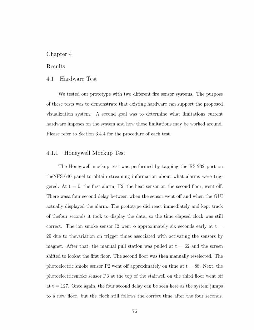
Chapter 4
Results
4.1 Hardware Test
We tested our prototype with two different fire sensor systems. The purpose
of these tests was to demonstrate that existing hardware can support the proposed
visualization system. A second goal was to determine what limitations current
hardware imposes on the system and how those limitations may be worked around.
Please refer to Section 3.4.4 for the procedure of each test.
4.1.1 Honeywell Mockup Test
The Honeywell mockup test was performed by tapping the RS-232 port on
theNFS-640 panel to obtain streaming information about what alarms were trig-
gered. At t = 0, the first alarm, H2, the heat sensor on the second floor, went off.
There wasa four second delay between when the sensor went off and when the GUI
actually displayed the alarm. The prototype did react immediately and kept track
of thefour seconds it took to display the data, so the time elapsed clock was still
correct. The ion smoke sensor I2 went o approximately six seconds early at t =
29 due to thevariation on trigger times associated with activating the sensors by
magnet. After that, the manual pull station was pulled at t = 62 and the screen
shifted to lookat the first floor. The second floor was then manually reselected. The
photoelectric smoke sensor P2 went off approximately on time at t = 88. Next, the
photoelectricsmoke sensor P3 at the top of the stairwell on the third floor went off
at t = 127. Once again, the four second delay can be seen here as the system jumps
to a new floor, but the clock still follows the correct time after the four seconds.
76
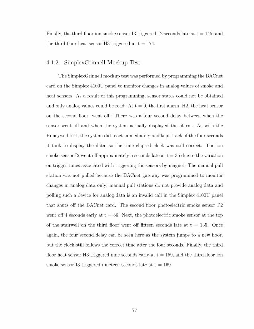
Finally, the third floor ion smoke sensor I3 triggered 12 seconds late at t = 145, and
the third floor heat sensor H3 triggered at t = 174.
4.1.2 SimplexGrinnell Mockup Test
The SimplexGrinnell mockup test was performed by programming the BACnet
card on the Simplex 4100U panel to monitor changes in analog values of smoke and
heat sensors. As a result of this programming, sensor states could not be obtained
and only analog values could be read. At t = 0, the first alarm, H2, the heat sensor
on the second floor, went off. There was a four second delay between when the
sensor went off and when the system actually displayed the alarm. As with the
Honeywell test, the system did react immediately and kept track of the four seconds
it took to display the data, so the time elapsed clock was still correct. The ion
smoke sensor I2 went off approximately 5 seconds late at t = 35 due to the variation
on trigger times associated with triggering the sensors by magnet. The manual pull
station was not pulled because the BACnet gateway was programmed to monitor
changes in analog data only; manual pull stations do not provide analog data and
polling such a device for analog data is an invalid call in the Simplex 4100U panel
that shuts off the BACnet card. The second floor photoelectric smoke sensor P2
went off 4 seconds early at t = 86. Next, the photoelectric smoke sensor at the top
of the stairwell on the third floor went off fifteen seconds late at t = 135. Once
again, the four second delay can be seen here as the system jumps to a new floor,
but the clock still follows the correct time after the four seconds. Finally, the third
floor heat sensor H3 triggered nine seconds early at t = 159, and the third floor ion
smoke sensor I3 triggered nineteen seconds late at t = 169.
77

4.1.3 Fire Progression
Key screenshots from the hardware tests have been selected and are presented
here. The selected screenshots show what the prototype displayed immediately
after each sensor was triggered. From these screenshots, a story of the fire has
been constructed as it would be understood by an observer who is familiar with the
system and has no information about the fire other than what is presented in the
screenshots.
(a) Honeywell (b) Simplex
Figure 4.1: Frame A
The above screenshots show that the fire originated on the second floor. The
fire probably started with a clean-burning material that did not trip the smoke
sensors. In the NFS-640 annotation file, only the corner appears in red, identifying
the zone of effect for the heat detector. In the 4100U annotation, the zone of effect
for the sensor is the whole floor, making it more difficult to visually understand
where the fire initially started, but still clearly shows what floor where the incident
began.
78
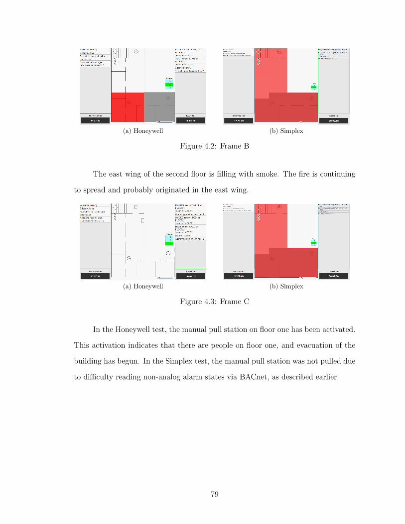
(a) Honeywell (b) Simplex
Figure 4.2: Frame B
The east wing of the second floor is filling with smoke. The fire is continuing
to spread and probably originated in the east wing.
(a) Honeywell (b) Simplex
Figure 4.3: Frame C
In the Honeywell test, the manual pull station on floor one has been activated.
This activation indicates that there are people on floor one, and evacuation of the
building has begun. In the Simplex test, the manual pull station was not pulled due
to difficulty reading non-analog alarm states via BACnet, as described earlier.
79
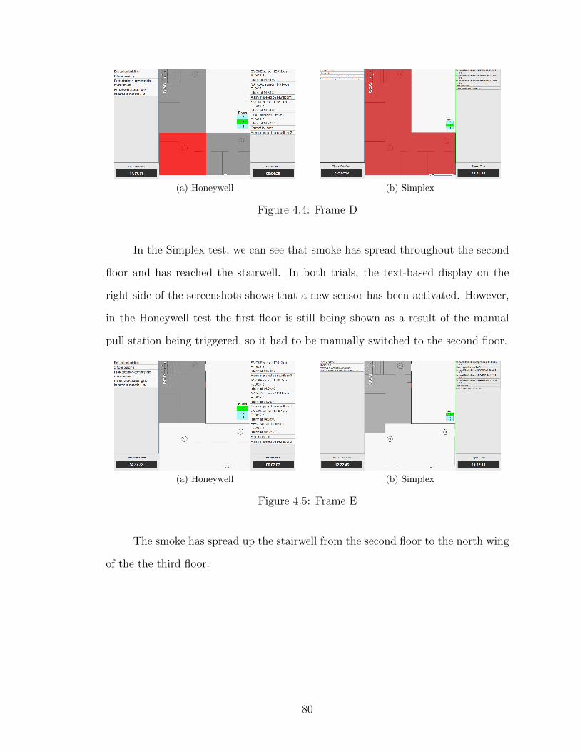
(a) Honeywell (b) Simplex
Figure 4.4: Frame D
In the Simplex test, we can see that smoke has spread throughout the second
floor and has reached the stairwell. In both trials, the text-based display on the
right side of the screenshots shows that a new sensor has been activated. However,
in the Honeywell test the first floor is still being shown as a result of the manual
pull station being triggered, so it had to be manually switched to the second floor.
(a) Honeywell (b) Simplex
Figure 4.5: Frame E
The smoke has spread up the stairwell from the second floor to the north wing
of the the third floor.
80
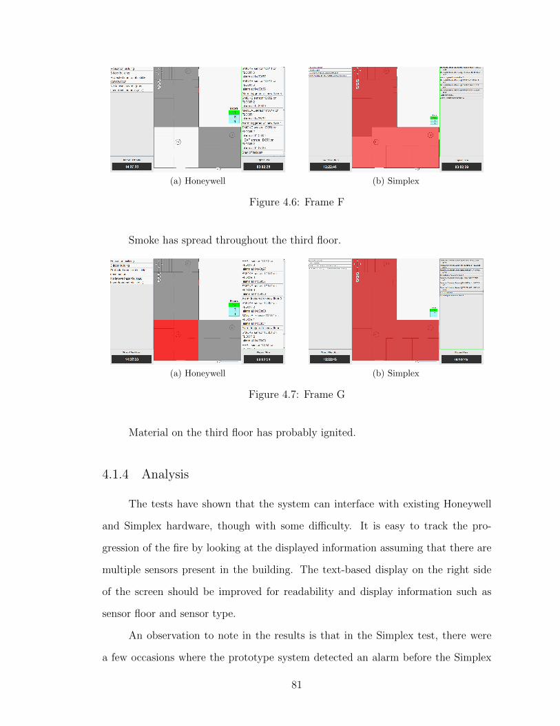
(a) Honeywell (b) Simplex
Figure 4.6: Frame F
Smoke has spread throughout the third floor.
(a) Honeywell (b) Simplex
Figure 4.7: Frame G
Material on the third floor has probably ignited.
4.1.4 Analysis
The tests have shown that the system can interface with existing Honeywell
and Simplex hardware, though with some difficulty. It is easy to track the pro-
gression of the fire by looking at the displayed information assuming that there are
multiple sensors present in the building. The text-based display on the right side
of the screen should be improved for readability and display information such as
sensor floor and sensor type.
An observation to note in the results is that in the Simplex test, there were
a few occasions where the prototype system detected an alarm before the Simplex
81

4100U panel did. This anomaly is most likely due to the fact that the BACnet plugin
for the system monitors the changes in analog values and detects alarms based on
the threshold values of the sensors being reached. The 4100U most likely has more
sophisticated measures that prevent it from picking up nuisance alarms, thus the
slight delay in setting off the alarm to be more confident that it is real.
In addition to the output of the prototype system, the normal output of the
printer port from the Notifier NFS-640 Panel was taken and is shown below:
ALARM: HEAT(FIXED) DETECTOR ADDR 1D053 Z001 04 :15P012411 1D053
ACKNOWLEDGE 04:16P012411 Mon
ALARM: SMOKE (ION) DETECTOR ADDR 1D051 Z002 04 :16P012411 1D051
ACKNOWLEDGE 04:16P012411 Mon
ALARM: MONITOR MODULE ADDR 1M014 Z004 04 :16P012411 1M014
ACKNOWLEDGE 04:17P012411 Mon
ALARM: SMOKE(PHOTO) DETECTOR ADDR 1D052 Z003 04 :17P012411 1D052
ACKNOWLEDGE 04:17P012411 Mon
ALARM: SMOKE(PHOTO) DETECTOR ADDR 1D012 Z003 04 :18P012411 1D012
ACKNOWLEDGE 04:18P012411 Mon
ALARM: SMOKE (ION) DETECTOR ADDR 1D011 Z002 04 :18P012411 1D011
ACKNOWLEDGE 04:18P012411 Mon
ALARM: HEAT(FIXED) DETECTOR ADDR 1D013 Z001 04 :18P012411 1D013
82

ACKNOWLEDGE 04:18P012411 Mon
As can be seen in the default configuration of the panel, simply reading the
alarm states as they go off makes it hard to gain a visual perspective of the scenario,
and harder to get a visual picture of the progression. Custom labeling of the sensors
could aid in this process, since this is a small building with few sensors, but in larger
configurations, it would be much more difficult to get a full visual picture of how
the fire started and how it has progressed. The visual nature of the prototype, as
well as its replay feature, can potentially aid in providing an image of the spread of
the fire in a building.
4.2 FDS Testing of GUI
4.2.1 Test 1 Results
A qualitative analysis of the correlation between the fire activity in the FDS
simulation and the GUI of our decision support tool prototype was undertaken.
Images from the FDS and the GUI were compared at one-minute intervals to assess
the accuracy of the view of fire progression through the decision support tool. This
assessment was done by matching rooms with smoke visible in Smokeview with
rooms showing smoke detector activations in the GUI. The timeline used was based
on the SmokeView simulation. The GUI time-of-first-alarm is approximately 65
seconds after the Smokeview timeline begins. Refer to Section 3.5.3 for the full
procedure of this test.
4.2.1.1 JMP Scenario
A visual assessment of the decision support tool’s display for the JMP simu-
lation in comparison to the SmokeView images showed only two incongruities. At
83
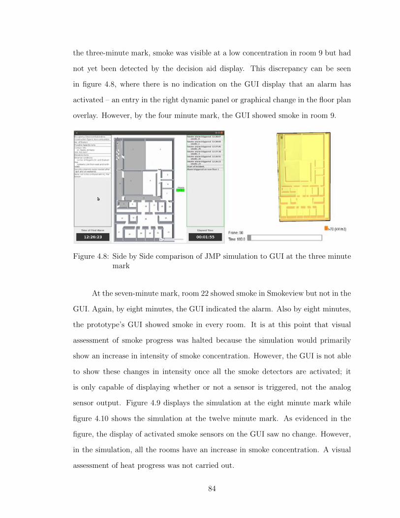
the three-minute mark, smoke was visible at a low concentration in room 9 but had
not yet been detected by the decision aid display. This discrepancy can be seen
in figure 4.8, where there is no indication on the GUI display that an alarm has
activated – an entry in the right dynamic panel or graphical change in the floor plan
overlay. However, by the four minute mark, the GUI showed smoke in room 9.
Figure 4.8: Side by Side comparison of JMP simulation to GUI at the three minutemark
At the seven-minute mark, room 22 showed smoke in Smokeview but not in the
GUI. Again, by eight minutes, the GUI indicated the alarm. Also by eight minutes,
the prototype’s GUI showed smoke in every room. It is at this point that visual
assessment of smoke progress was halted because the simulation would primarily
show an increase in intensity of smoke concentration. However, the GUI is not able
to show these changes in intensity once all the smoke detectors are activated; it
is only capable of displaying whether or not a sensor is triggered, not the analog
sensor output. Figure 4.9 displays the simulation at the eight minute mark while
figure 4.10 shows the simulation at the twelve minute mark. As evidenced in the
figure, the display of activated smoke sensors on the GUI saw no change. However,
in the simulation, all the rooms have an increase in smoke concentration. A visual
assessment of heat progress was not carried out.
84
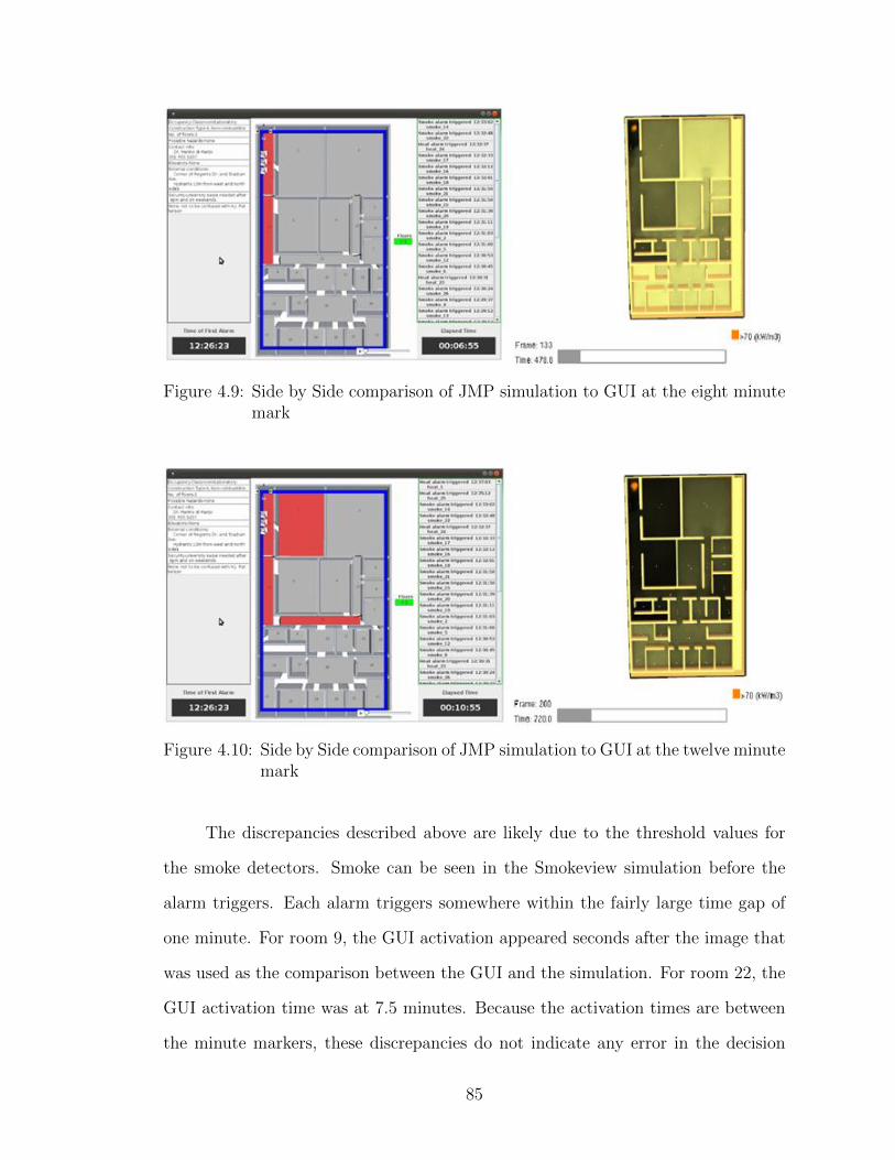
Figure 4.9: Side by Side comparison of JMP simulation to GUI at the eight minutemark
Figure 4.10: Side by Side comparison of JMP simulation to GUI at the twelve minutemark
The discrepancies described above are likely due to the threshold values for
the smoke detectors. Smoke can be seen in the Smokeview simulation before the
alarm triggers. Each alarm triggers somewhere within the fairly large time gap of
one minute. For room 9, the GUI activation appeared seconds after the image that
was used as the comparison between the GUI and the simulation. For room 22, the
GUI activation time was at 7.5 minutes. Because the activation times are between
the minute markers, these discrepancies do not indicate any error in the decision
85
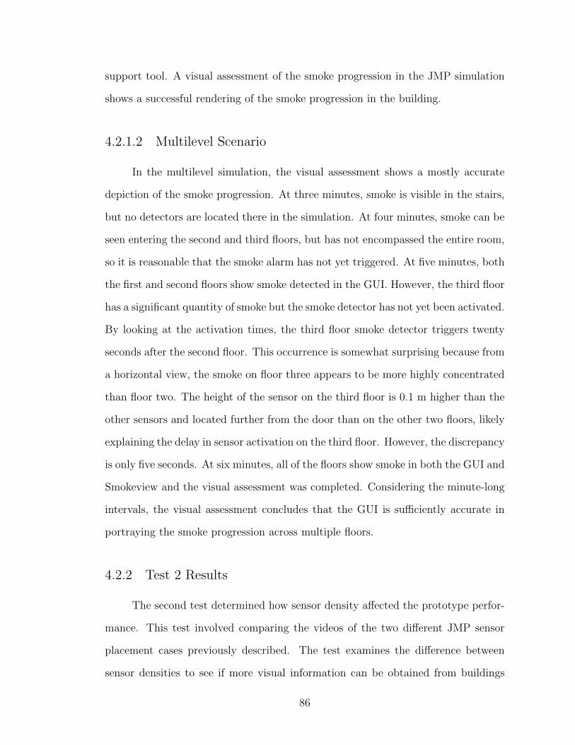
support tool. A visual assessment of the smoke progression in the JMP simulation
shows a successful rendering of the smoke progression in the building.
4.2.1.2 Multilevel Scenario
In the multilevel simulation, the visual assessment shows a mostly accurate
depiction of the smoke progression. At three minutes, smoke is visible in the stairs,
but no detectors are located there in the simulation. At four minutes, smoke can be
seen entering the second and third floors, but has not encompassed the entire room,
so it is reasonable that the smoke alarm has not yet triggered. At five minutes, both
the first and second floors show smoke detected in the GUI. However, the third floor
has a significant quantity of smoke but the smoke detector has not yet been activated.
By looking at the activation times, the third floor smoke detector triggers twenty
seconds after the second floor. This occurrence is somewhat surprising because from
a horizontal view, the smoke on floor three appears to be more highly concentrated
than floor two. The height of the sensor on the third floor is 0.1 m higher than the
other sensors and located further from the door than on the other two floors, likely
explaining the delay in sensor activation on the third floor. However, the discrepancy
is only five seconds. At six minutes, all of the floors show smoke in both the GUI and
Smokeview and the visual assessment was completed. Considering the minute-long
intervals, the visual assessment concludes that the GUI is sufficiently accurate in
portraying the smoke progression across multiple floors.
4.2.2 Test 2 Results
The second test determined how sensor density affected the prototype perfor-
mance. This test involved comparing the videos of the two different JMP sensor
placement cases previously described. The test examines the difference between
sensor densities to see if more visual information can be obtained from buildings
86
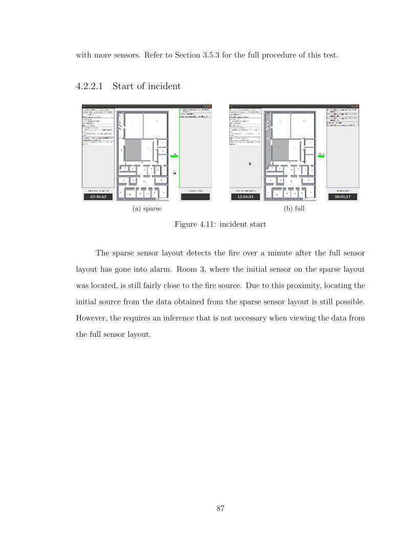
with more sensors. Refer to Section 3.5.3 for the full procedure of this test.
4.2.2.1 Start of incident
(a) sparse (b) full
Figure 4.11: incident start
The sparse sensor layout detects the fire over a minute after the full sensor
layout has gone into alarm. Room 3, where the initial sensor on the sparse layout
was located, is still fairly close to the fire source. Due to this proximity, locating the
initial source from the data obtained from the sparse sensor layout is still possible.
However, the requires an inference that is not necessary when viewing the data from
the full sensor layout.
87

4.2.2.2 Flow switch activation: Four minutes from start of fire
(a) sparse (b) full
Figure 4.12: flow switch activation
By this point, the full layout shows that the smoke has spread across the
building. The sparse layout shows a very different picture, with sensors in alarm
only in the top left corner of the building. The sparse case does not correctly
represent the spread of smoke. The movement of smoke is more clearly seen by the
full sensor layout.
About half of the building’s smoke sensors are in alarm in both scenarios – two
out of five are in alarm for the sparse case, and twelve out of twenty-seven for the
full case. However, without an indication for which rooms have sensors, the sparse
case appears to under-represent the extent to which smoke has spread. The fact
that only two sensors are in alarm for the sparse case could be deceiving.
88
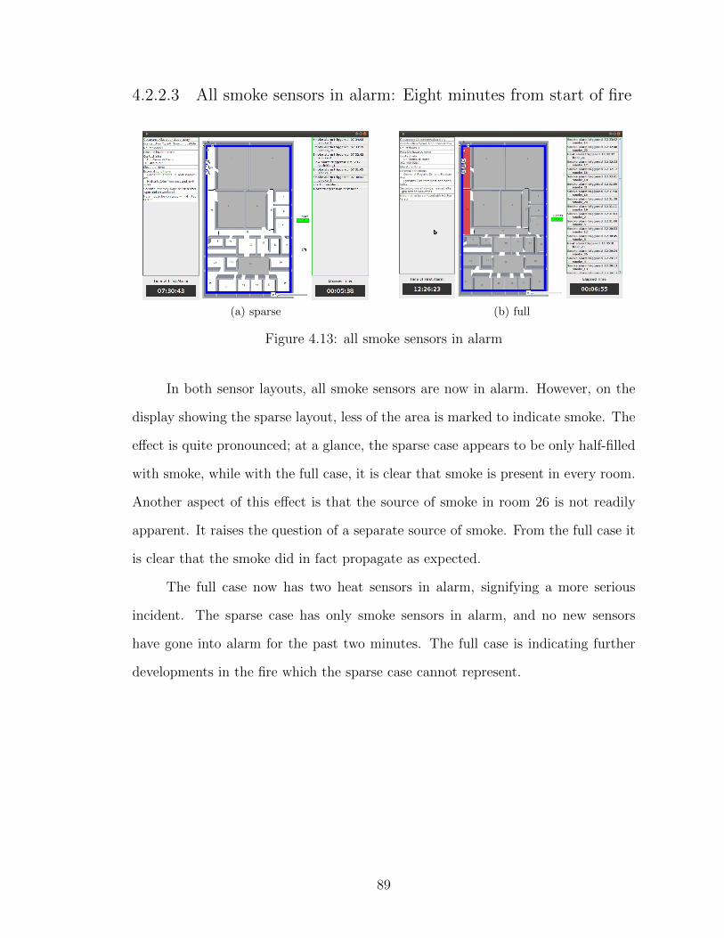
4.2.2.3 All smoke sensors in alarm: Eight minutes from start of fire
(a) sparse (b) full
Figure 4.13: all smoke sensors in alarm
In both sensor layouts, all smoke sensors are now in alarm. However, on the
display showing the sparse layout, less of the area is marked to indicate smoke. The
effect is quite pronounced; at a glance, the sparse case appears to be only half-filled
with smoke, while with the full case, it is clear that smoke is present in every room.
Another aspect of this effect is that the source of smoke in room 26 is not readily
apparent. It raises the question of a separate source of smoke. From the full case it
is clear that the smoke did in fact propagate as expected.
The full case now has two heat sensors in alarm, signifying a more serious
incident. The sparse case has only smoke sensors in alarm, and no new sensors
have gone into alarm for the past two minutes. The full case is indicating further
developments in the fire which the sparse case cannot represent.
89
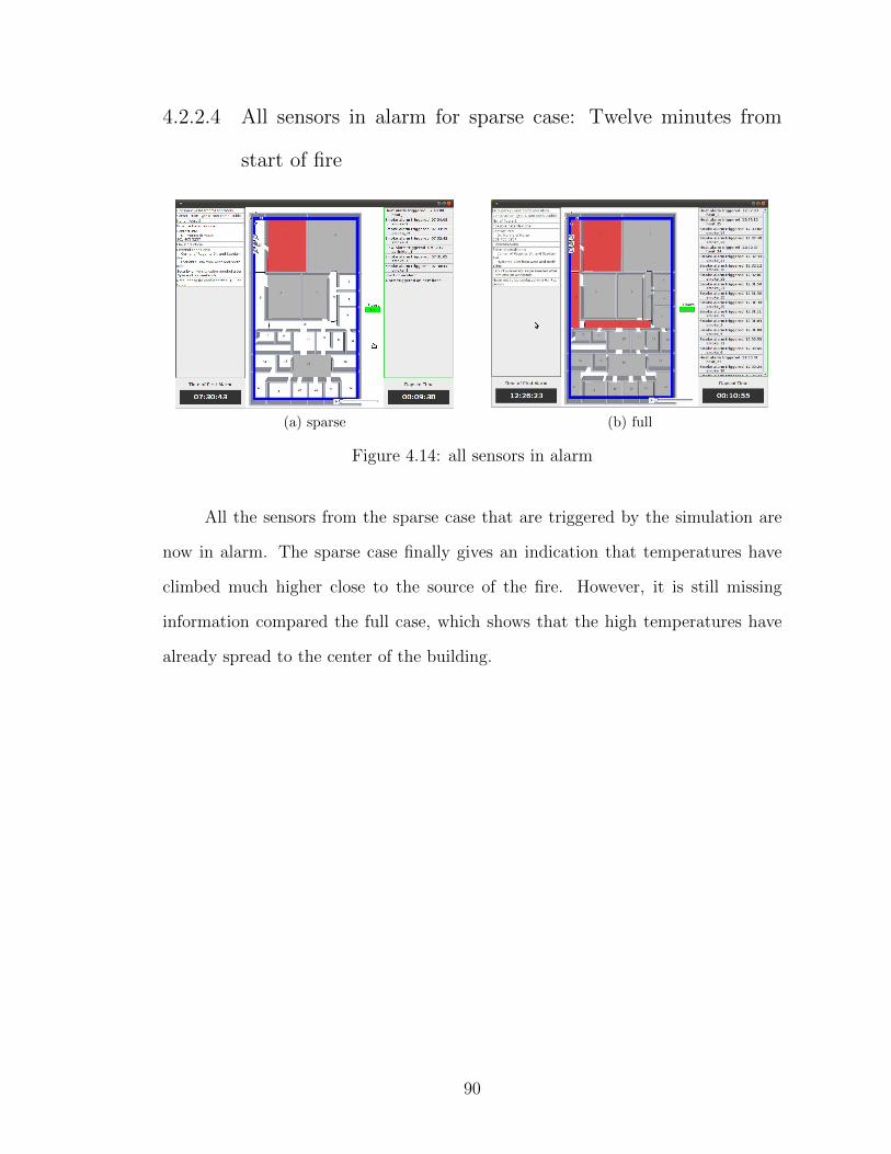
4.2.2.4 All sensors in alarm for sparse case: Twelve minutes from
start of fire
(a) sparse (b) full
Figure 4.14: all sensors in alarm
All the sensors from the sparse case that are triggered by the simulation are
now in alarm. The sparse case finally gives an indication that temperatures have
climbed much higher close to the source of the fire. However, it is still missing
information compared the full case, which shows that the high temperatures have
already spread to the center of the building.
90
Chapter 5
Conclusions
Currently, EFRs accessing building sensor data are given sensor activation data
sequentially and without context. A clear picture of the situation in the building
is virtually inaccessible from textual input of this sort. We proposed a decision
support tool to interpret building sensor data and visualize the progression of a
developing fire emergency situation. The goal was to provide a visual representation
of the emergency as accurately as possible to key decision making personnel using
only technology already available in buildings. We developed a prototype decision
support tool to show that a decision aid display can be an effective and feasible way
to provide valuable information to incident commanders. The prototype was tested
by using sensor activation inputs as well as virtual simulation inputs to verify the
prototypes capability to handle physical sensor data and the prototypes ability to
track fire emergency development accurately.
Using a sequence of triggered alarms, the prototype demonstrated that it could
successfully handle sensor data inputs. In current systems, RS-232 has been a
common form of data output for printers commonly connected to FACPs. Basic
printer output from FACPs did not provide any useful visual context of the fire
progression. When the same data from the printer output is used as an input for the
prototype decision support tool, the GUI clearly shows the events of the emergency
scenario in real-time. The delay between sensor activation and visualization of the
GUI was minimal (four second maximum) and was in large part due to inefficiencies
of the chosen programming language, Java, and the hardware limitations of the lab
laptop. Tests with physical sensor inputs demonstrate that a decision support tool
connect to existing building sensor systems and provide more effective information.
91
In order to perform experiments on a larger scale, virtual simulations of fire
scenarios were created in FDS. The virtual sensor output of the FDS simulations
was used as the input to the prototype. Then the visual outputs of Smokeview and
the GUI were compared. There were two virtual experiments. One experiment was
an analysis of a residential sized building with three sensors per floor and a total
of three levels. This multi-level experiment was of a scale similar in size and sensor
density to the hardware tests. The virtual experiments matched the general results
of the hardware experiments and reached the same conclusions.
The next FDS experiment was of a significantly larger scale and sensor den-
sity, in a replication of the J.M. Patterson building at the University of Maryland.
This comparison demonstrated that the progression of a fire emergency situation
in a full-scale building can be accurately portrayed by a visualization tool. The
experiment was run in two parts, one with a low sensor density (the real, as-built
sensor configuration) and one with a high sensor density, closer to an ideal case.
In the case of the low density test, the results showed that it was very difficult
to get a detailed view of the progression of the fire. However, in the high density
experiment, the progression of the fire was clear and identifiable. The high density
scenario provided more at-a-glance information for EFRs. In addition, the stage of
development of the fire was more readily apparent by comparing the progression of
activated smoke sensors to heat sensors. While a higher senor density leads to a
more precise picture, even in low sensor density configurations, the visual display
provides more at-a-glance information than the plain text output of an FACP.
5.0.3 Future Directions
The system proposed in this project has many potential implications for its
own portion of the industry as well as others. The future directions inspired by this
project fall into two distinct categories: advances that can be made to improve the
92
decision support tool itself, and advances to the industry that vastly increase the
potential of incorporating such a system.
For advances to the system itself, there are many improvements to be made.
Further work can be done to streamline the user interface (UI) and maximize the
human interfacing components of potential hardware that could be used. Currently,
the software is in a proof-of-concept phase, running on any computer installed. It is
envisioned to be installed on touchscreen devices like Toughbooks and other tablet
devices for fast, intuitive touch interaction. In order to get to the envisioned state,
more research on human interfacing must be considered. Usability testing needs to
be done to determine what kind of difference this tool makes in EFR response to
an emergency. Questions such as “Do EFRs make more effective decisions or make
decisions significantly faster with the decision support tool?” are paramount in
justifying its advanced development. Also, research to evaluate whether or not too
much information is displayed is imperative. Optimizing the hardware and software
for use by first responders is a key step in order for a system to be practically
adopted.
Other advances to the decision support tool include increasing the variety of
kinds of input it can adopt. The tool is designed to easily add new sensor technolo-
gies in a modular way. Annotations of floor plans can be updated to include new
devices. The result is that there is room for new technology to get more and increas-
ingly sophisticated data for analysis by the decision support tool. Inclusions that
could be made based on current technology include adding in HVAC sensors, secu-
rity systems and structural health monitoring devices. HVAC sensors can provide
further information on the air flows within a building structure, monitor humid-
ity, and track water flows. Security systems offer access to motion sensors which
could be used to monitor motion in rooms due to either smoke current or persons
still inside a building. Additionally, they provide security cameras that have video
93
feeds that could be used to provide an internal view of the building. Such cameras
combined with infrared camera technology or new devices such as fire and smoke
sensing cameras could bring significant visual data. Through cameras, the progres-
sion of fire and the location of civilians and EFRs within a building could be seen in
detail. Additional technology that could be included is GPS tracking of individual
EFRs within a building. While it is most likely a more complicated inclusion, it is
potentially valuable information when responding to an emergency. Thorough and
properly visualized inclusion of current technology could provide a whole new realm
of data to aid first responders in analyzing an emergency scenario.
With modularity being a key goal of the system, taking in new types of data
as new technologies evolve is also crucial. Ideally, new sensors that are able to more
accurately monitor temperature, structural integrity and overall building health
could be used to predict dangerous scenarios like flashover or building collapse.
Predictive analysis based on accurate sensor data could potentially save lives. It is
essential that, as the proposed decision support tool evolves, modularity stays at
the forefront of priorities in its future direction.
For the industry, significant changes could lead to innovation and development
in advances for emergency technology. An important recommendation for a new
standard is increasing the requirements for building sensor configurations. As shown
in the sensor density experiments, more sensors installed in a building allows for a
more accurate visualization of the fire scenario. Requiring more senors would greatly
increase the benefits of decision aid displays like the tested prototype, but may not
be cost effective. Further cost-benefit analysis should be undertaken. The single
biggest recommendation for the future that could be made is the adoption of a
unified standard for a protocol of sensor and other building data. Such a standard
is essential for the decision support tool to be able to take in new inputs. BACnet,
a protocol used in the experiments by our team, is a good start at such a standard.
94
It makes the outputs of sensors unified and currently works across fire sensors and
HVAC sensors. However, it does not have the capacity to deal with new kinds of
sensor systems such as security or EFR tracking systems. Also, our experimentation
with BACnet was limited to a sensor mockup of only twelve input devices. On a
full sized building, there could be orders of magnitude more sensors to incorporate.
The refresh rate of the BACnet protocol may not be fast enough to handle real-time
monitoring of data on this scale. Further experimentation is necessary to confirm
this fact.
Another important standard for the proposed system is NEMA SB 30, the
standard that outlines how visuals are shown on an interface for EFRs. A key point
for adoption of a new technology by first responders is a consistent visual interface.
All layouts, symbols, colors and indicators need to be standardized across every
display in order for there to be no new learning curve moving from device to device.
As another direction, the industry could work to advance technology in order
to increase the potential of the proposed tool. Making sensors more robust in
emergency scenarios (e.g., more heat resistant so they fail at a later time in fire
scenarios), making them take in higher ranges of data at faster rates, and increasing
the variety of data available could contribute to increasing the information available
to first responders. Ultimately, the goal of the system is to provide better data for
EFRs to make more informed decisions.
While discussing future directions of this complex system, there are also chal-
lenges to consider. Widespread implementation of the proposed decision support
tool would require initial training of EFRs. There are both logistical and financial
costs associated with such a significant amount of training. The economic challenges
of mass hardware implementation must also be recognized. Conveniently, the sys-
tem is primarily software in nature and could run on already existing hardware in
the field such as Toughbooks. However, not all fire departments have the necessary
95

technology. Furthermore, if a new standard protocol is implemented, the fire sensor
industry and all additional sensor industries that would become included will need
to adopt that protocol and make appropriate hardware accommodations. While
this project did not attempt to address these issues, in future work on this kind of
system, it would be important to consider them.
96
Appendix A
Features List
Static/Pre-planning Sidebar
• The purpose of the static sidebar is to provide a synopsis of the buildinginvolved in the emergency situation. Firefighters will use this informationbefore they arrive at the scene. This information will be displayed on the leftside of the display in plain text. The following information, if available, MUSTbe displayed in this sidebar in the following order.
• Occupancy (notation) assembly, business, educational, factory, high-hazard,institutional, mercantile, residential, storage, utilities, miscellaneous (Interna-tional Building Code 2006)
• Construction (notation) fire-resistive non-combustible, protected non-combustible,unprotected non-combustible, protected combustible, unprotected combustible,heavy timber, protected wood frame, unprotected wood frame
• Number of floors
• Possible hazards- chemical, gas tanks, biological, radioactive
• Display time of first alarm in 24-hour mode in hours-minutes-seconds (i.e.,20:15:30, as opposed to 08:15:30 P.M.).
Dynamic Alert Sidebar
• The purpose of the dynamic sidebar is to display all important alerts that haveoccurred during the duration of the emergency situation. This information willbe displayed on the right side of the display in plain text.
• Display elapsed time since first alarm
• Display alarms chronologically with newest alarms on top. Alarms notated as:sprinklers active, smoke alarm, heat alarm, chemical alarm, chem. suppression,pull station
• Should state location of alarms by room, sprinklers by zone
• Should time stamp in 24 hour time
• Scroll bar if space of window for display is exceeded
97
• Display first alarm of each floor and time occurred
Floor Plan
• The purpose of the floor plan is to allow Incident Commanders to visuallypinpoint the locations of sensors in alarm and other items of importance. Thedynamic information displayed will be overlaid on a static, two-dimensionalfloor plan. The system will utilize NEMA SB 30 icons and icons created by ourteam. Only sensors in alarm will be displayed on the floor plan; idle sensorswill be hidden from view.
• The floor plan should be draggable (if possible) but at minimum, move basedon arrows.
• The following items must be displayed on the floor plan:
• Location and state of smoke detectors (NEMA SB 30)
• Rooms with active smoke detectors will be shaded grey.
• If a room is determined to contain both smoke and heat, the room will beshaded red. The presence of fire will take precedence over the presence ofsmoke.
• Location of activated heat sensors (NEMA SB 30)
• Rooms determined to have heat detector going off will be shaded red
• Location of activated hazardous material (hazmat) detectors (NEMA SB 30)
• Rooms determined to have activated hazmat detectors will be shaded green
• Rooms with hazmat and heat detectors activated will be striped green andred
• Rooms with hazmat and smoke detectors activated will be striped green andgray
• Location of hazardous materials; chemical, biological, radioactive (NEMA SB30)
• Location of troubled sensors (NEMA SB 30)
• Sensors in alarm that stop reporting will display most recent state and troubledsymbol
• Location of high-pressure gas storage (NEMA SB 30)
• Locations of elevators/elevator controls (NEMA SB 30)
98
– Floor elevators on should be displayed on elevator icon
• Locations of stand pipes/fire hydrants (NEMA SB 30)
• Location of utility shutoff (gas, electric, water)
• Location of smoke vents and exhaust fans (NEMA SB 30)
• Locations of evacuation/pressurized stairs (NEMA SB 30)
• Location of standpipes and sprinkler shutoff (NEMA SB 30?)
• Locations of activated sprinkler systems
• Zones with activated sprinklers will be outlined in blue. Zones in a buildingwill not otherwise be displayed.
• Displayed zones will have centered label
• Locations of activated chemical suppression systems
• Outline room with activated chemical suppression systems will be outline inpurple.
Zoom (like Google Maps):
• Three button control
– Zoom in: Moves in a set magnification (will have to figure actual amountlater)
– Zoom out: Moves out a set magnification (Max zoom out is default view)
– Default: This button should set the map so that the entire floor is inview.
• Buttons will be placed at the upper left of the map
Replay:
• Scroll bar will allow flip through of the recorded map images
• Animation needs to be faster (several factors) than real time
• Animation will replace current map (Needs to be distinguished from real timeimage)
• Wherever scroll bar is dragged and dropped, it will continue playing till itreaches current situation
99
• Pressing the play button starts the animation at the beginning and plays tothe end
• Only the map area will be affected by replay; all other areas functions asnormal
Floor control:
• Two areas to pick floors; first is floors in alarm, 2nd is complete list of floors
• Incident Commanders will have the ability to change floors through a scrollfunction, point-and-click on the floor of interest
• The system will default to the floor where the first alarm occurred.
Pop-up Alert Window Area
• The purpose of the popup alert window is to display current special alerts andcrucial warnings to Incident Commanders. The pop-up alert window will belocated in the lower section of the screen directly below the floor plan.
• Pop-up will appear with sound and will not close until acknowledged
• Newest alert will be in front of stack of pop ups
• Information on the pop-up will show up on the dynamic sidebar when pop upappears
• The following alerts will be displayed in the pop-up window:
– When an alarm goes off on another floor (notated as: Alert: Alarm onfloor X)
– When a sprinkler systems activates (notated as: Alert: Sprinklers acti-vated, floor X, zone Y)
– When a chemical/special hazard occurs (notated as: Alert: K hazard,floor X, room Z)
– When a chemical suppression system activates (notated as: Chemicalsuppression systems activate, floor X, room Z)
100
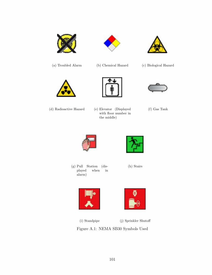
(a) Troubled Alarm (b) Chemical Hazard (c) Biological Hazard
(d) Radioactive Hazard (e) Elevator (Displayedwith floor number inthe middle)
(f) Gas Tank
(g) Pull Station (dis-played when inalarm)
(h) Stairs
(i) Standpipe (j) Sprinkler Shutoff
Figure A.1: NEMA SB30 Symbols Used
101
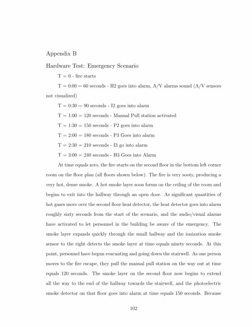
Appendix B
Hardware Test: Emergency Scenario
T = 0 - fire starts
T = 0:00 = 60 seconds - H2 goes into alarm, A/V alarms sound (A/V sensors
not visualized)
T = 0:30 = 90 seconds - I2 goes into alarm
T = 1:00 = 120 seconds - Manual Pull station activated
T = 1:30 = 150 seconds - P2 goes into alarm
T = 2:00 = 180 seconds - P3 Goes into alarm
T = 2:30 = 210 seconds - I3 go into alarm
T = 3:00 = 240 seconds - H3 Goes into Alarm
At time equals zero, the fire starts on the second floor in the bottom left corner
room on the floor plan (all floors shown below). The fire is very sooty, producing a
very hot, dense smoke. A hot smoke layer soon forms on the ceiling of the room and
begins to exit into the hallway through an open door. As significant quantities of
hot gases move over the second floor heat detector, the heat detector goes into alarm
roughly sixty seconds from the start of the scenario, and the audio/visual alarms
have activated to let personnel in the building be aware of the emergency. The
smoke layer expands quickly through the small hallway and the ionization smoke
sensor to the right detects the smoke layer at time equals ninety seconds. At this
point, personnel have begun evacuating and going down the stairwell. As one person
moves to the fire escape, they pull the manual pull station on the way out at time
equals 120 seconds. The smoke layer on the second floor now begins to extend
all the way to the end of the hallway towards the stairwell, and the photoelectric
smoke detector on that floor goes into alarm at time equals 150 seconds. Because
102

the stairwell doors have been left open, the smoke enters the stairwell and rises,
entering the third floor. Because of the increased burning conditions of the initial
fire, the smoke layer is very hot and very dense, thus moving up the stairwell at a
rapid rate. At time equals 180 seconds, the third floor photoelectric smoke detector
has been triggered. Soon, it starts spreading into the hallway due to the stairwell
door being left open during the evacuation process. By time equals 210 seconds,
the ionization smoke sensor has gone into alarm as the smoke rapidly fills the third
floor. At time t=240, the third floor heat detector ha been triggered. The scenario
has concluded at this point.
Figure B.1: Floor 1
103
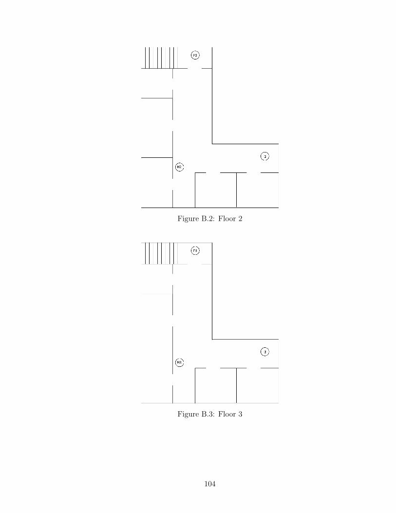
Figure B.2: Floor 2
Figure B.3: Floor 3
104
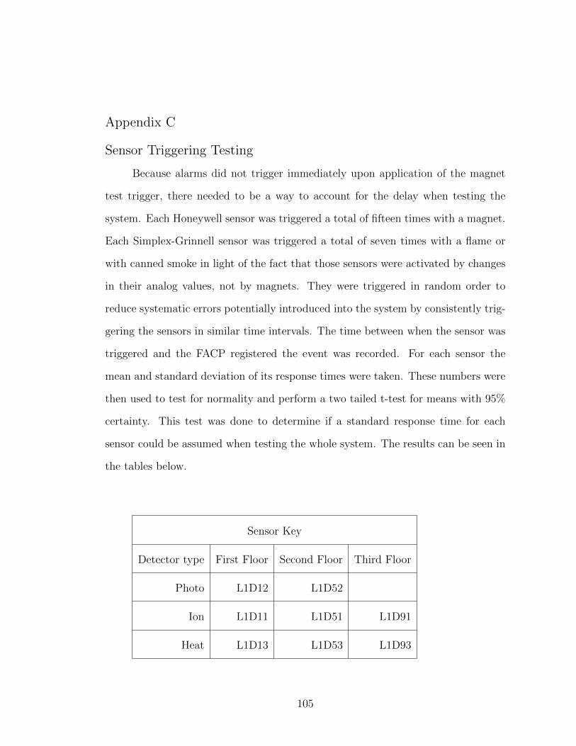
Appendix C
Sensor Triggering Testing
Because alarms did not trigger immediately upon application of the magnet
test trigger, there needed to be a way to account for the delay when testing the
system. Each Honeywell sensor was triggered a total of fifteen times with a magnet.
Each Simplex-Grinnell sensor was triggered a total of seven times with a flame or
with canned smoke in light of the fact that those sensors were activated by changes
in their analog values, not by magnets. They were triggered in random order to
reduce systematic errors potentially introduced into the system by consistently trig-
gering the sensors in similar time intervals. The time between when the sensor was
triggered and the FACP registered the event was recorded. For each sensor the
mean and standard deviation of its response times were taken. These numbers were
then used to test for normality and perform a two tailed t-test for means with 95%
certainty. This test was done to determine if a standard response time for each
sensor could be assumed when testing the whole system. The results can be seen in
the tables below.
Sensor Key
Detector type First Floor Second Floor Third Floor
Photo L1D12 L1D52
Ion L1D11 L1D51 L1D91
Heat L1D13 L1D53 L1D93
105

Sensor Name Time (seconds)
L1D12 16.78
13.76
16.97
16.62
14.60
18.93
18.72
16.90
17.53
17.67
Mean 16.85
STDEV 1.62
Sensor Name Time (seconds)
L1D52 14.39
17.46
9.52
15.57
16.90
8.24
14.74
17.04
14.40
17.83
Mean 14.61
STDEV 3.29
Sensor Name Time (seconds)
L1D11 8.31
7.96
8.17
6.70
6.84
9.09
7.12
7.12
7.28
7.47
Mean 7.61
STDEV 0.76
Sensor Name Time (seconds)
L1D51 7.12
6.91
7.82
7.47
14.88
8.16
6.84
9.92
6.84
Mean 8.44
STDEV 2.60
106

Sensor Name Time (seconds)
L1D13 6.00
5.93
5.86
7.40
6.56
6.70
6.49
8.45
9.22
8.59
Mean 7.12
STDEV 1.23
Sensor Name Time (seconds)
L1D53 6.78
7.26
6.07
8.24
7.57
9.71
7.47
9.01
4.40
6.70
Mean 7.32
STDEV 1.50
Sensor Name Time (seconds)
L1D91 7.05
8.24
8.11
9.08
7.41
8.66
8.45
7.40
9.71
6.84
Mean 8.10
STDEV 0.92
Sensor Name Time (seconds)
L1D93 9.08
7.40
7.54
8.38
6.84
9.22
8.87
8.45
8.24
11.39
7.48
Mean 8.44
STDEV 1.24
107
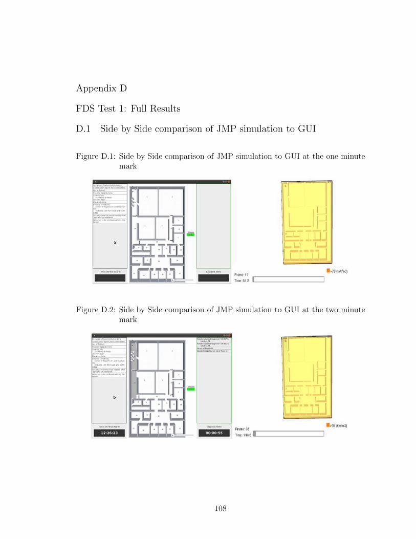
Appendix D
FDS Test 1: Full Results
D.1 Side by Side comparison of JMP simulation to GUI
Figure D.1: Side by Side comparison of JMP simulation to GUI at the one minutemark
Figure D.2: Side by Side comparison of JMP simulation to GUI at the two minutemark
108

Figure D.3: Side by Side comparison of JMP simulation to GUI at the three minutemark
Figure D.4: Side by Side comparison of JMP simulation to GUI at the four minutemark
Figure D.5: Side by Side comparison of JMP simulation to GUI at the five minutemark
109
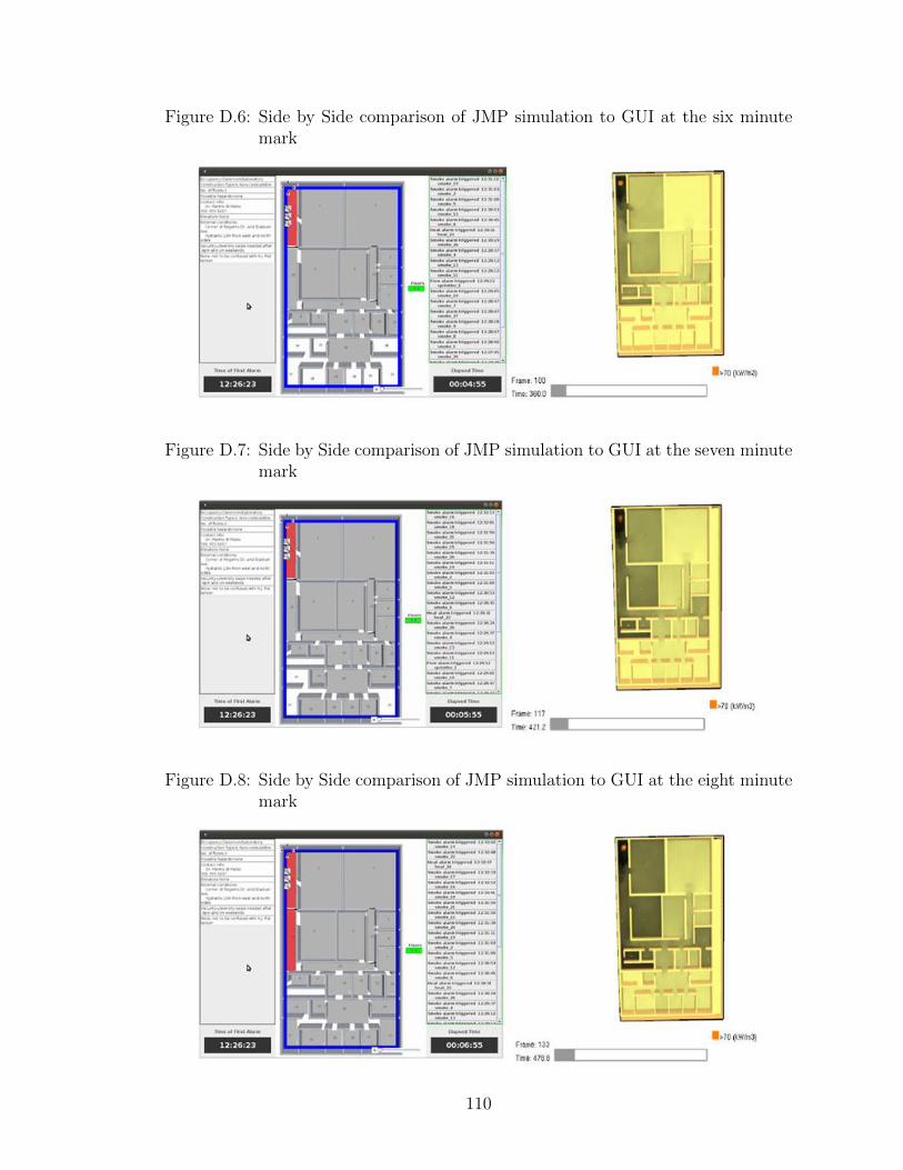
Figure D.6: Side by Side comparison of JMP simulation to GUI at the six minutemark
Figure D.7: Side by Side comparison of JMP simulation to GUI at the seven minutemark
Figure D.8: Side by Side comparison of JMP simulation to GUI at the eight minutemark
110
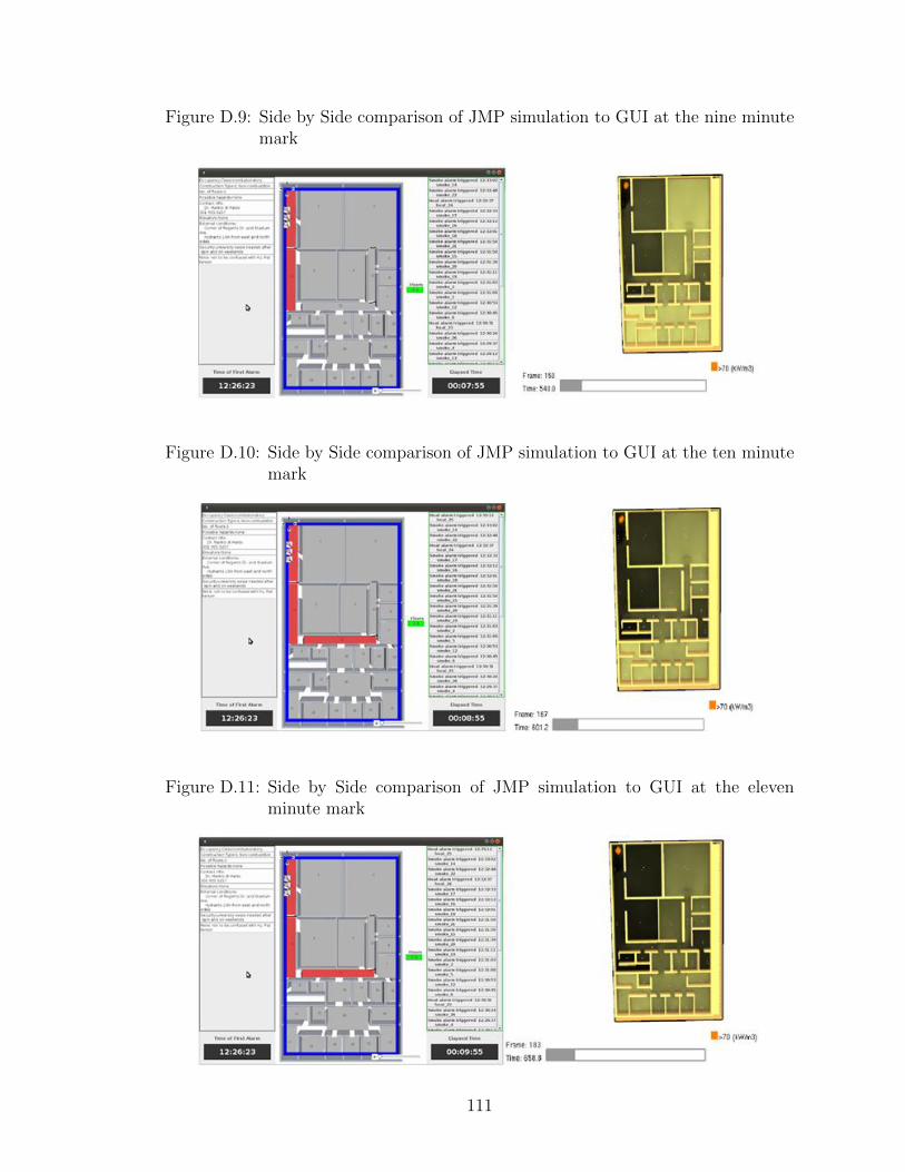
Figure D.9: Side by Side comparison of JMP simulation to GUI at the nine minutemark
Figure D.10: Side by Side comparison of JMP simulation to GUI at the ten minutemark
Figure D.11: Side by Side comparison of JMP simulation to GUI at the elevenminute mark
111
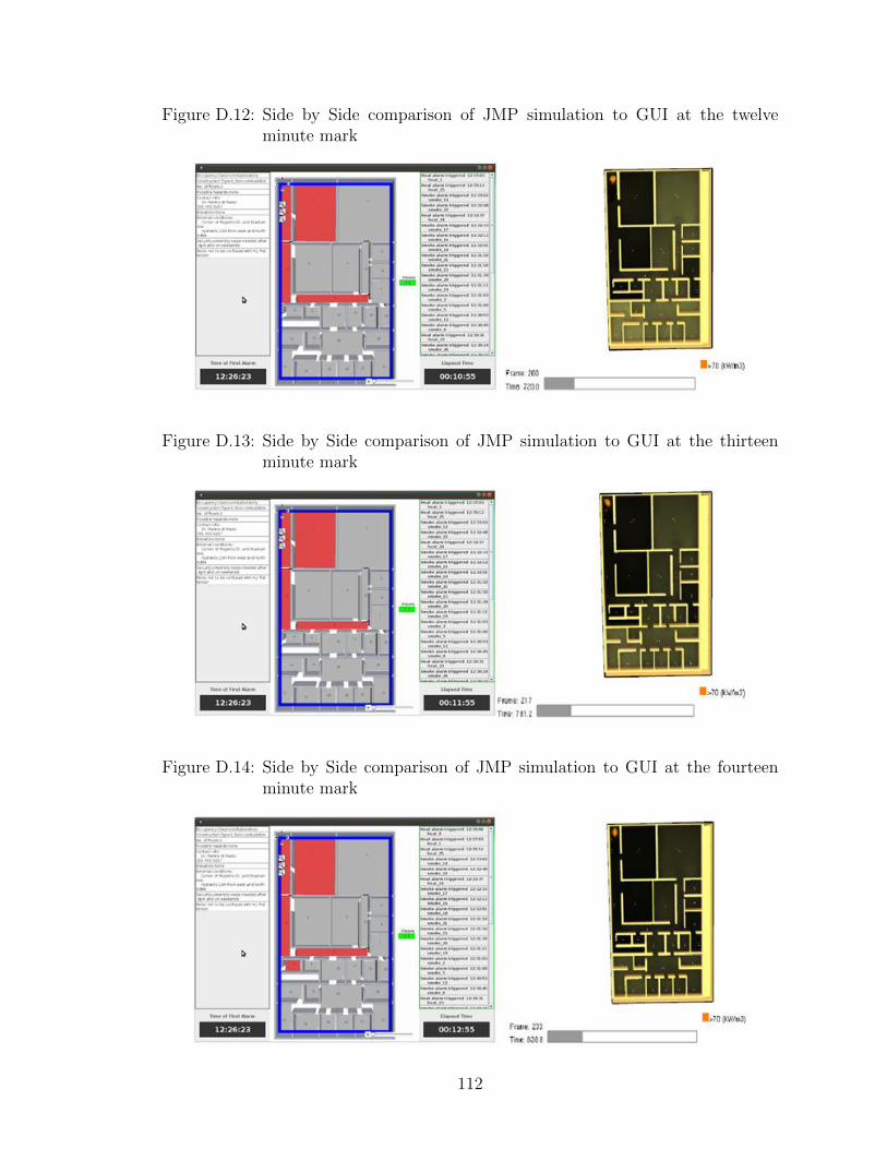
Figure D.12: Side by Side comparison of JMP simulation to GUI at the twelveminute mark
Figure D.13: Side by Side comparison of JMP simulation to GUI at the thirteenminute mark
Figure D.14: Side by Side comparison of JMP simulation to GUI at the fourteenminute mark
112

Figure D.15: Side by Side comparison of JMP simulation to GUI at the fifteenminute mark
Figure D.16: Side by Side comparison of JMP simulation to GUI at the sixteenminute mark
Figure D.17: Side by Side comparison of JMP simulation to GUI at the seventeenminute mark
113

D.2 Side by Side comparison of Multilevel simulation to GUI
Figure D.18: Side by Side comparison of Multilevel simulation to GUI at the oneminute mark
Figure D.19: Side by Side comparison of Multilevel simulation to GUI at the twominute mark
114
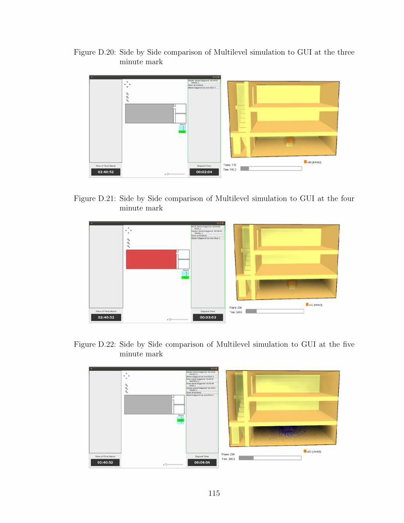
Figure D.20: Side by Side comparison of Multilevel simulation to GUI at the threeminute mark
Figure D.21: Side by Side comparison of Multilevel simulation to GUI at the fourminute mark
Figure D.22: Side by Side comparison of Multilevel simulation to GUI at the fiveminute mark
115

Appendix E
FDS Code
E.1 JMP FDS code
&HEAD CHID=’ jmp fs ’&MESH IJK=120 ,120 ,12 , XB= 0 . 0 , 4 0 , 0 . 0 , 2 5 , 0 . 0 , 4 . 0 , COLOR=’BLACK’ /&TIME T END=3600. /∗ s i n g l e burner , no ob j ec t s , 30 min run
&SURF ID=’FIRE ’ ,HRRPUA=10000.0 ,TAU Q=−600.00/&OBST XB= 1 . 5 , 2 , 1 . 5 , 2 , 0 , 1 . 5 , SURF IDS=’FIRE ’ , ’ INERT’ , ’ INERT’ /&PART ID=’water drops ’ , WATER=.TRUE. , SAMPLING FACTOR=1 /
&PROP ID=’Acme Spr ink l e r ’ , QUANTITY=’SPRINKLER LINK TEMPERATURE’ , RTI=95, C FACTOR=0.4 ,
ACTIVATION TEMPERATURE=68, OFFSET=0.10 ,PART ID=’water drops ’ ,FLOW RATE=189.3 ,
DROPLET VELOCITY=10. , SPRAY ANGLE=30. ,80 . /
&PROP ID=’Acme Smoke Detector ’ , QUANTITY=’CHAMBER OBSCURATION’ , LENGTH=1.8 , ACTIVATION OBSCURATION=3.28 /
&PROP ID=’Acme Heat ’ , QUANTITY=’LINK TEMPERATURE’ , RTI=132. ,ACTIVATION TEMPERATURE=74. /
∗smoke de t e c t o r&DEVC XYZ=6 ,17 ,3 .9 , ID=’smoke 2 ’ , PROP ID=’Acme Smoke Detector ’ /&DEVC XYZ=6 ,7 ,3 .9 , ID=’smoke 1 ’ , PROP ID=’Acme Smoke Detector ’ /&DEVC XYZ=6 ,1 ,3 .9 , ID=’smoke 23 ’ , PROP ID=’Acme Smoke Detector ’ /&DEVC XYZ=14 ,20 .5 ,3 .9 , ID=’smoke 5 ’ , PROP ID=’Acme Smoke Detector ’ /&DEVC XYZ=17 .5 , 20 . 5 , 3 . 9 , ID=’smoke 6 ’ , PROP ID=’Acme Smoke Detector ’ /&DEVC XYZ=22 ,20 .5 ,3 .9 , ID=’smoke 7 ’ , PROP ID=’Acme Smoke Detector ’ /&DEVC XYZ=17 ,17 ,3 .9 , ID=’smoke 27 ’ , PROP ID=’Acme Smoke Detector ’ /&DEVC XYZ=17.5 ,13 ,3 .9 , ID=’smoke 4 ’ , PROP ID=’Acme Smoke Detector ’ /&DEVC XYZ=17 .5 , 6 . 333 , 3 . 9 , ID=’smoke 3 ’ , PROP ID=’Acme Smoke Detector ’ /&DEVC XYZ=18 ,1 ,3 .9 , ID=’smoke 24 ’ , PROP ID=’Acme Smoke Detector ’ /&DEVC XYZ=25 .5 ,3 ,3 .9 , ID=’smoke 8 ’ , PROP ID=’Acme Smoke Detector ’ /&DEVC XYZ=25 .5 , 6 . 5 , 3 . 9 , ID=’smoke 9 ’ , PROP ID=’Acme Smoke Detector ’ /&DEVC XYZ=26 .5 , 10 . 5 , 3 . 9 , ID=’smoke 10 ’ , PROP ID=’Acme Smoke Detector ’ /&DEVC XYZ=26.5 ,15 ,3 .9 , ID=’smoke 11 ’ , PROP ID=’Acme Smoke Detector ’ /&DEVC XYZ=26.5 ,18 ,3 .9 , ID=’smoke 12 ’ , PROP ID=’Acme Smoke Detector ’ /&DEVC XYZ=26 .5 ,21 .3333 ,3 .9 , ID=’smoke 13 ’ , PROP ID=’Acme Smoke Detector
’ /&DEVC XYZ=31 ,2 .5 ,3 .9 , ID=’smoke 14 ’ , PROP ID=’Acme Smoke Detector ’ /&DEVC XYZ=31 ,7 ,3 .9 , ID=’smoke 15 ’ , PROP ID=’Acme Smoke Detector ’ /
116
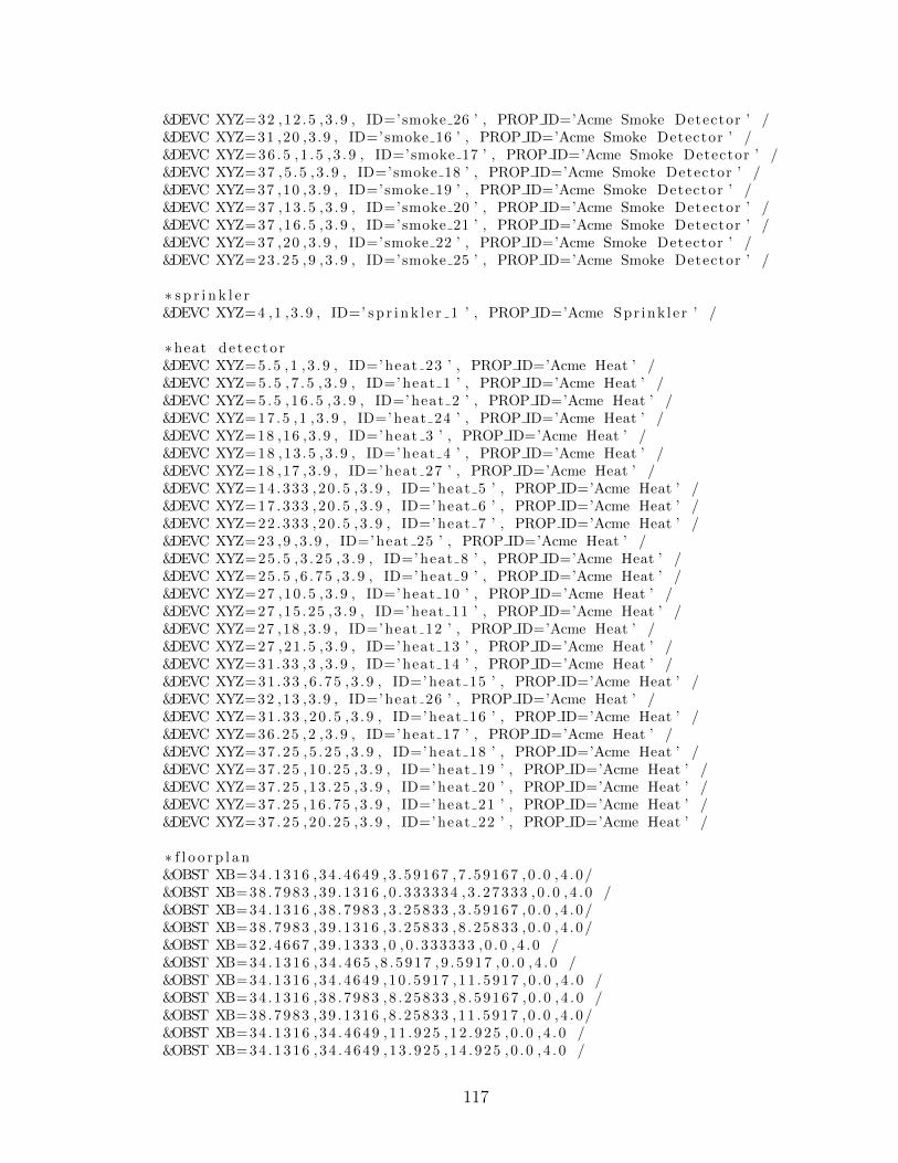
&DEVC XYZ=32 ,12 .5 ,3 .9 , ID=’smoke 26 ’ , PROP ID=’Acme Smoke Detector ’ /&DEVC XYZ=31 ,20 ,3 .9 , ID=’smoke 16 ’ , PROP ID=’Acme Smoke Detector ’ /&DEVC XYZ=36 .5 , 1 . 5 , 3 . 9 , ID=’smoke 17 ’ , PROP ID=’Acme Smoke Detector ’ /&DEVC XYZ=37 ,5 .5 ,3 .9 , ID=’smoke 18 ’ , PROP ID=’Acme Smoke Detector ’ /&DEVC XYZ=37 ,10 ,3 .9 , ID=’smoke 19 ’ , PROP ID=’Acme Smoke Detector ’ /&DEVC XYZ=37 ,13 .5 ,3 .9 , ID=’smoke 20 ’ , PROP ID=’Acme Smoke Detector ’ /&DEVC XYZ=37 ,16 .5 ,3 .9 , ID=’smoke 21 ’ , PROP ID=’Acme Smoke Detector ’ /&DEVC XYZ=37 ,20 ,3 .9 , ID=’smoke 22 ’ , PROP ID=’Acme Smoke Detector ’ /&DEVC XYZ=23.25 ,9 ,3 .9 , ID=’smoke 25 ’ , PROP ID=’Acme Smoke Detector ’ /
∗ s p r i n k l e r&DEVC XYZ=4 ,1 ,3 .9 , ID=’ s p r i n k l e r 1 ’ , PROP ID=’Acme Spr ink l e r ’ /
∗heat de t e c t o r&DEVC XYZ=5.5 ,1 , 3 . 9 , ID=’ heat 23 ’ , PROP ID=’Acme Heat ’ /&DEVC XYZ=5 . 5 , 7 . 5 , 3 . 9 , ID=’ heat 1 ’ , PROP ID=’Acme Heat ’ /&DEVC XYZ=5 .5 , 16 . 5 , 3 . 9 , ID=’ heat 2 ’ , PROP ID=’Acme Heat ’ /&DEVC XYZ=17 .5 ,1 ,3 .9 , ID=’ heat 24 ’ , PROP ID=’Acme Heat ’ /&DEVC XYZ=18 ,16 ,3 .9 , ID=’ heat 3 ’ , PROP ID=’Acme Heat ’ /&DEVC XYZ=18 ,13 .5 ,3 .9 , ID=’ heat 4 ’ , PROP ID=’Acme Heat ’ /&DEVC XYZ=18 ,17 ,3 .9 , ID=’ heat 27 ’ , PROP ID=’Acme Heat ’ /&DEVC XYZ=14 .333 ,20 .5 , 3 . 9 , ID=’ heat 5 ’ , PROP ID=’Acme Heat ’ /&DEVC XYZ=17 .333 ,20 .5 , 3 . 9 , ID=’ heat 6 ’ , PROP ID=’Acme Heat ’ /&DEVC XYZ=22 .333 ,20 .5 , 3 . 9 , ID=’ heat 7 ’ , PROP ID=’Acme Heat ’ /&DEVC XYZ=23 ,9 ,3 .9 , ID=’ heat 25 ’ , PROP ID=’Acme Heat ’ /&DEVC XYZ=25 .5 , 3 . 25 , 3 . 9 , ID=’ heat 8 ’ , PROP ID=’Acme Heat ’ /&DEVC XYZ=25 .5 , 6 . 75 , 3 . 9 , ID=’ heat 9 ’ , PROP ID=’Acme Heat ’ /&DEVC XYZ=27 ,10 .5 ,3 .9 , ID=’ heat 10 ’ , PROP ID=’Acme Heat ’ /&DEVC XYZ=27 ,15 .25 ,3 .9 , ID=’ heat 11 ’ , PROP ID=’Acme Heat ’ /&DEVC XYZ=27 ,18 ,3 .9 , ID=’ heat 12 ’ , PROP ID=’Acme Heat ’ /&DEVC XYZ=27 ,21 .5 ,3 .9 , ID=’ heat 13 ’ , PROP ID=’Acme Heat ’ /&DEVC XYZ=31.33 ,3 ,3 .9 , ID=’ heat 14 ’ , PROP ID=’Acme Heat ’ /&DEVC XYZ=31 .33 , 6 . 75 , 3 . 9 , ID=’ heat 15 ’ , PROP ID=’Acme Heat ’ /&DEVC XYZ=32 ,13 ,3 .9 , ID=’ heat 26 ’ , PROP ID=’Acme Heat ’ /&DEVC XYZ=31 .33 , 20 . 5 , 3 . 9 , ID=’ heat 16 ’ , PROP ID=’Acme Heat ’ /&DEVC XYZ=36.25 ,2 ,3 .9 , ID=’ heat 17 ’ , PROP ID=’Acme Heat ’ /&DEVC XYZ=37 .25 , 5 . 25 , 3 . 9 , ID=’ heat 18 ’ , PROP ID=’Acme Heat ’ /&DEVC XYZ=37 .25 ,10 .25 , 3 . 9 , ID=’ heat 19 ’ , PROP ID=’Acme Heat ’ /&DEVC XYZ=37 .25 ,13 .25 , 3 . 9 , ID=’ heat 20 ’ , PROP ID=’Acme Heat ’ /&DEVC XYZ=37 .25 ,16 .75 , 3 . 9 , ID=’ heat 21 ’ , PROP ID=’Acme Heat ’ /&DEVC XYZ=37 .25 ,20 .25 , 3 . 9 , ID=’ heat 22 ’ , PROP ID=’Acme Heat ’ /
∗ f l o o r p l a n&OBST XB=34 .1316 , 34 . 4649 , 3 . 59167 , 7 . 59167 , 0 . 0 , 4 . 0/&OBST XB=38 .7983 , 39 . 1316 , 0 . 333334 ,3 . 27333 ,0 . 0 , 4 . 0 /&OBST XB=34 .1316 , 38 . 7983 , 3 . 25833 , 3 . 59167 , 0 . 0 , 4 . 0/&OBST XB=38 .7983 , 39 . 1316 , 3 . 25833 , 8 . 25833 , 0 . 0 , 4 . 0/&OBST XB=32 .4667 , 39 . 1333 , 0 , 0 . 333333 ,0 . 0 , 4 . 0 /&OBST XB=34 .1316 , 34 . 465 , 8 . 5917 , 9 . 5917 , 0 . 0 , 4 . 0 /&OBST XB=34 .1316 , 34 . 4649 , 10 . 5917 , 11 . 5917 , 0 . 0 , 4 . 0 /&OBST XB=34 .1316 , 38 . 7983 , 8 . 25833 , 8 . 59167 , 0 . 0 , 4 . 0 /&OBST XB=38 .7983 , 39 . 1316 , 8 . 25833 , 11 . 5917 , 0 . 0 , 4 . 0/&OBST XB=34 .1316 , 34 . 4649 , 11 . 925 , 12 . 925 , 0 . 0 , 4 . 0 /&OBST XB=34 .1316 , 34 . 4649 , 13 . 925 , 14 . 925 , 0 . 0 , 4 . 0 /
117

&OBST XB=34 .1316 , 38 . 7983 , 11 . 5917 , 11 . 925 , 0 . 0 , 4 . 0 /&OBST XB=38 .7983 , 39 . 1316 , 11 . 5917 , 14 . 925 , 0 . 0 , 4 . 0 /&OBST XB= 3 0 . 0 , 3 2 . 5 , 8 . 3 3 3 , 8 . 6 6 6 3 3 , 0 . 0 , 4 . 0 /&OBST XB=28 .885 , 32 . 135 , 5 . 333 , 5 . 66633 , 0 . 0 , 4 . 0 /&OBST XB=32 .1333 , 32 . 4667 , 5 . 333 , 8 . 333 , 0 . 0 , 4 . 0 /&OBST XB=32 .135 , 32 . 4683 , 0 . 333333 , 3 . 99999 , 0 . 0 , 4 . 0 /&OBST XB=28 .885 , 32 . 4683 , 0 . 0 , 0 . 333333 , 0 . 0 , 4 . 0 /&OBST XB=34 .1316 , 34 . 4649 , 15 . 2584 , 15 . 5917 , 0 . 0 , 4 . 0 /&OBST XB=34 .1316 , 38 . 7983 , 14 . 925 , 15 . 2584 , 0 . 0 , 4 . 0 /&OBST XB=38 .7983 , 39 . 1316 , 14 . 925 , 18 . 2584 , 0 . 0 , 4 . 0 /&OBST XB=34 .137 , 34 . 4703 , 16 . 666 , 18 . 2533 , 0 . 0 , 4 . 0 /&OBST XB=34 .137 , 38 . 803 , 18 . 2533 , 18 . 5867 , 0 . 0 , 4 . 0 /&OBST XB=38 .7983 , 39 . 1317 , 18 . 2583 , 22 . 3417 , 0 . 0 , 4 . 0 /&OBST XB=32 .4667 , 39 . 1333 , 22 . 3333 , 22 . 6667 , 0 . 0 , 4 . 0 /&OBST XB=29 .8888 , 32 . 4721 , 16 . 666 , 16 . 9994 , 0 . 0 , 4 . 0 /&OBST XB=32 .1388 , 32 . 4721 , 16 . 9994 , 22 . 3327 , 0 . 0 , 4 . 0 /&OBST XB=28 .8888 , 32 . 4721 , 22 . 3333 , 22 . 6667 , 0 . 0 , 4 . 0 /&OBST XB=28 .55 , 28 . 8833 , 0 . 332967 , 8 . 33297 , 0 . 0 , 4 . 0 /&OBST XB=2 3 . 885 , 28 . 885 , 0 . 0 , 0 . 33 3333 , 0 . 0 , 4 . 0 /&OBST XB=1 2 . 335 , 23 . 885 , 0 . 0 , 0 . 33 3333 , 0 . 0 , 4 . 0 /&OBST XB=23 .8867 , 25 . 5533 , 1 . 16666 , 1 . 49999 , 0 . 0 , 4 . 0 /&OBST XB=23 .8833 , 24 . 2167 , 1 . 49999 , 4 . 99999 , 0 . 0 , 4 . 0 /&OBST XB=26 .55 , 26 . 8833 , 1 . 16334 , 4 . 99667 , 0 . 0 , 4 . 0 /&OBST XB=26 .5533 , 26 . 8867 , 5 . 33315 , 8 . 33315 , 0 . 0 , 4 . 0 /&OBST XB=23 .8833 , 26 . 8833 , 4 . 99999 , 5 . 33333 , 0 . 0 , 4 . 0 /&OBST XB=23 .8833 , 24 . 2167 , 7 . 33333 , 8 . 33333 , 0 . 0 , 4 . 0 /&OBST XB=23 .8833 , 24 . 2167 , 5 . 3333 , 6 . 3333 , 0 . 0 , 4 . 0 /&OBST XB=28 .55 , 28 . 8833 , 8 . 6663 , 10 . 1663 , 0 . 0 , 4 . 0 /&OBST XB=23 .8833 , 28 . 8833 , 8 . 33297 , 8 . 6663 , 0 . 0 , 4 . 0 /&OBST XB=23 .8833 , 24 . 2167 , 8 . 6663 , 10 . 1663 , 0 . 0 , 4 . 0 /&OBST XB=28 .55 , 28 . 8833 , 11 . 6663 , 13 . 1663 , 0 . 0 , 4 . 0 /&OBST XB=23 .8833 , 24 . 2167 , 11 . 6663 , 13 . 1663 , 0 . 0 , 4 . 0 /&OBST XB=28 .55 , 28 . 8833 , 13 . 4997 , 14 . 4997 , 0 . 0 , 4 . 0 /&OBST XB= 2 8 . 5 5 3 3 , 2 8 . 8 8 6 7 , 1 5 . 5 , 1 6 . 5 , 0 . 0 , 4 . 0 /&OBST XB=23 .8833 , 28 . 8833 , 13 . 1663 , 13 . 4997 , 0 . 0 , 4 . 0 /&OBST XB= 2 3 . 8 8 3 3 , 2 4 . 2 1 6 7 , 1 3 . 5 , 1 4 . 5 , 0 . 0 , 4 . 0 /&OBST XB= 2 3 . 8 8 6 7 , 2 4 . 2 2 , 1 5 . 5 , 1 6 . 5 , 0 . 0 , 4 . 0 /&OBST XB=24 .22 , 27 . 5533 , 16 . 5033 , 16 . 8367 , 0 . 0 , 4 . 0 /&OBST XB=28 .5533 , 28 . 8867 , 16 . 5033 , 19 . 3367 , 0 . 0 , 4 . 0 /&OBST XB= 1 5 . 0 , 2 1 . 6 6 6 7 , 3 . 0 , 3 . 3 3 3 3 3 , 0 . 0 , 4 . 0 /&OBST XB=21 .6667 , 22 . 0 , 2 . 99934 , 10 . 3327 , 0 . 0 , 4 . 0 /&OBST XB=12 .3333 , 21 . 6667 , 10 . 3333 , 10 . 6667 , 0 . 0 , 4 . 0 /&OBST XB=21 .6667 , 22 . 0 , 10 . 3333 , 14 . 6667 , 0 . 0 , 4 . 0 /&OBST XB=13 .3333 , 22 . 0 , 15 . 9019 , 16 . 2352 , 0 . 0 , 4 . 0 /&OBST XB=23 .8867 , 24 . 22 , 16 . 5033 , 19 . 3367 , 0 . 0 , 4 . 0 /&OBST XB=23 .9133 , 24 . 2467 , 20 . 82 , 22 . 32 , 0 . 0 , 4 . 0 /&OBST XB=23 .8867 , 28 . 5533 , 19 . 3333 , 19 . 6667 , 0 . 0 , 4 . 0 /&OBST XB=28 .5533 , 28 . 8867 , 19 . 3333 , 22 . 3333 , 0 . 0 , 4 . 0 /&OBST XB=24 .2221 , 28 . 8888 , 22 . 3333 , 22 . 6667 , 0 . 0 , 4 . 0 /&OBST XB=19 .3267 , 22 . 9933 , 17 . 8333 , 18 . 1667 , 0 . 0 , 4 . 0 /&OBST XB=19 .3333 , 24 . 2221 , 22 . 3333 , 22 . 6667 , 0 . 0 , 4 . 0 /&OBST XB=16 .6666 , 18 . 9999 , 17 . 8333 , 18 . 1667 , 0 . 0 , 4 . 0 /&OBST XB=18 .9999 , 19 . 3333 , 17 . 83 , 22 . 33 , 0 . 0 , 4 . 0 /&OBST XB=16 .0 , 19 . 3333 , 22 . 3333 , 22 . 6667 , 0 . 0 , 4 . 0 /
118
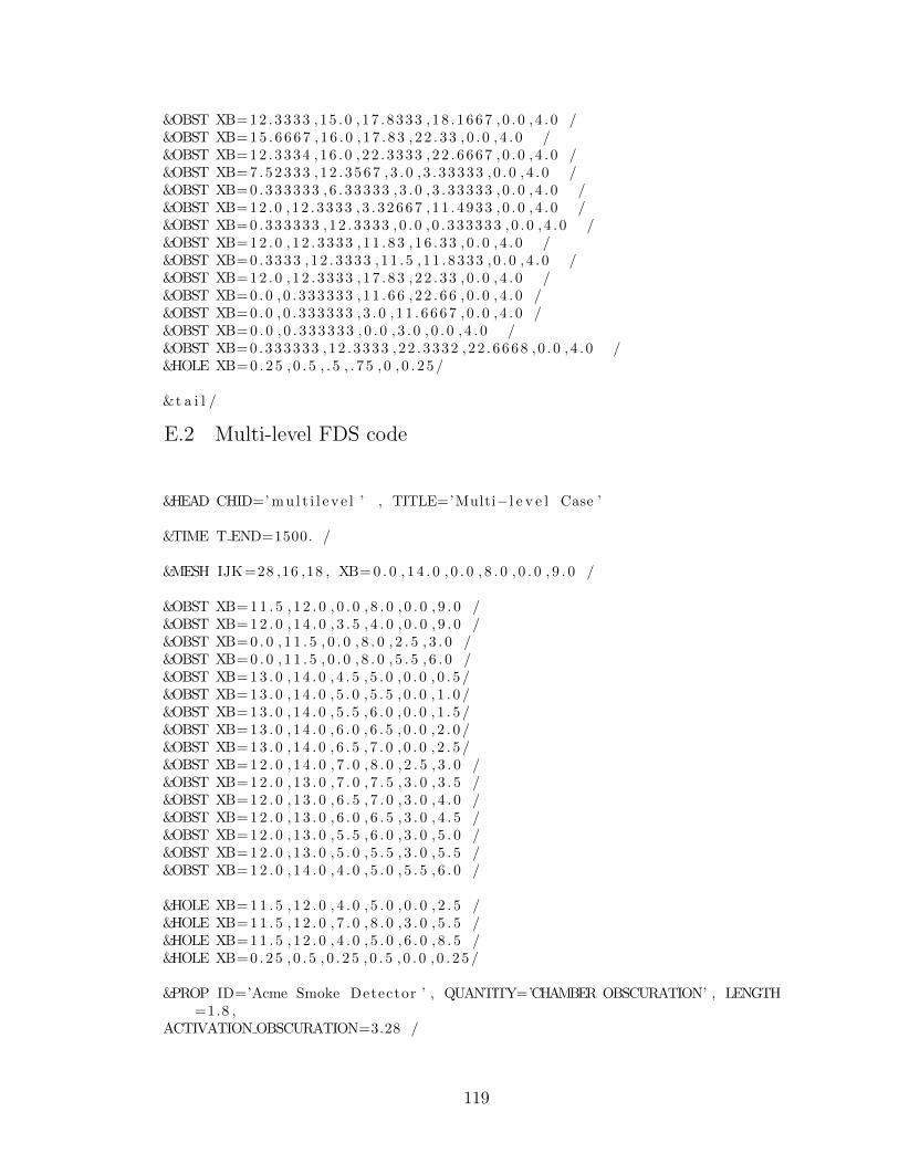
&OBST XB=12 .3333 , 15 . 0 , 17 . 8333 , 18 . 1667 , 0 . 0 , 4 . 0 /&OBST XB= 1 5 . 6 6 6 7 , 1 6 . 0 , 1 7 . 8 3 , 2 2 . 3 3 , 0 . 0 , 4 . 0 /&OBST XB=12 .3334 , 16 . 0 , 22 . 3333 , 22 . 6667 , 0 . 0 , 4 . 0 /&OBST XB=7 .52333 , 12 . 3567 , 3 . 0 , 3 . 33333 , 0 . 0 , 4 . 0 /&OBST XB=0 .333333 , 6 . 33333 , 3 . 0 , 3 . 33333 , 0 . 0 , 4 . 0 /&OBST XB=12 .0 , 12 . 3333 , 3 . 32667 , 11 . 4933 , 0 . 0 , 4 . 0 /&OBST XB=0 .333333 , 12 . 3333 , 0 . 0 , 0 . 333333 , 0 . 0 , 4 . 0 /&OBST XB= 1 2 . 0 , 1 2 . 3 3 3 3 , 1 1 . 8 3 , 1 6 . 3 3 , 0 . 0 , 4 . 0 /&OBST XB=0 .3333 , 12 . 3333 , 11 . 5 , 11 . 8333 , 0 . 0 , 4 . 0 /&OBST XB= 1 2 . 0 , 1 2 . 3 3 3 3 , 1 7 . 8 3 , 2 2 . 3 3 , 0 . 0 , 4 . 0 /&OBST XB= 0 . 0 , 0 . 3 3 3 3 3 3 , 1 1 . 6 6 , 2 2 . 6 6 , 0 . 0 , 4 . 0 /&OBST XB= 0 . 0 , 0 . 3 3 3 3 3 3 , 3 . 0 , 1 1 . 6 6 6 7 , 0 . 0 , 4 . 0 /&OBST XB= 0 . 0 , 0 . 3 3 3 3 3 3 , 0 . 0 , 3 . 0 , 0 . 0 , 4 . 0 /&OBST XB=0.333333 ,12 . 3333 , 22 . 3332 , 22 . 6668 , 0 . 0 , 4 . 0 /&HOLE XB= 0 . 2 5 , 0 . 5 , . 5 , . 7 5 , 0 , 0 . 2 5 /
&t a i l /
E.2 Multi-level FDS code
&HEAD CHID=’ m u l t i l e v e l ’ , TITLE=’Multi−l e v e l Case ’
&TIME T END=1500. /
&MESH IJK=28 ,16 ,18 , XB= 0 . 0 , 1 4 . 0 , 0 . 0 , 8 . 0 , 0 . 0 , 9 . 0 /
&OBST XB= 1 1 . 5 , 1 2 . 0 , 0 . 0 , 8 . 0 , 0 . 0 , 9 . 0 /&OBST XB= 1 2 . 0 , 1 4 . 0 , 3 . 5 , 4 . 0 , 0 . 0 , 9 . 0 /&OBST XB= 0 . 0 , 1 1 . 5 , 0 . 0 , 8 . 0 , 2 . 5 , 3 . 0 /&OBST XB= 0 . 0 , 1 1 . 5 , 0 . 0 , 8 . 0 , 5 . 5 , 6 . 0 /&OBST XB= 1 3 . 0 , 1 4 . 0 , 4 . 5 , 5 . 0 , 0 . 0 , 0 . 5 /&OBST XB= 1 3 . 0 , 1 4 . 0 , 5 . 0 , 5 . 5 , 0 . 0 , 1 . 0 /&OBST XB= 1 3 . 0 , 1 4 . 0 , 5 . 5 , 6 . 0 , 0 . 0 , 1 . 5 /&OBST XB= 1 3 . 0 , 1 4 . 0 , 6 . 0 , 6 . 5 , 0 . 0 , 2 . 0 /&OBST XB= 1 3 . 0 , 1 4 . 0 , 6 . 5 , 7 . 0 , 0 . 0 , 2 . 5 /&OBST XB= 1 2 . 0 , 1 4 . 0 , 7 . 0 , 8 . 0 , 2 . 5 , 3 . 0 /&OBST XB= 1 2 . 0 , 1 3 . 0 , 7 . 0 , 7 . 5 , 3 . 0 , 3 . 5 /&OBST XB= 1 2 . 0 , 1 3 . 0 , 6 . 5 , 7 . 0 , 3 . 0 , 4 . 0 /&OBST XB= 1 2 . 0 , 1 3 . 0 , 6 . 0 , 6 . 5 , 3 . 0 , 4 . 5 /&OBST XB= 1 2 . 0 , 1 3 . 0 , 5 . 5 , 6 . 0 , 3 . 0 , 5 . 0 /&OBST XB= 1 2 . 0 , 1 3 . 0 , 5 . 0 , 5 . 5 , 3 . 0 , 5 . 5 /&OBST XB= 1 2 . 0 , 1 4 . 0 , 4 . 0 , 5 . 0 , 5 . 5 , 6 . 0 /
&HOLE XB= 1 1 . 5 , 1 2 . 0 , 4 . 0 , 5 . 0 , 0 . 0 , 2 . 5 /&HOLE XB= 1 1 . 5 , 1 2 . 0 , 7 . 0 , 8 . 0 , 3 . 0 , 5 . 5 /&HOLE XB= 1 1 . 5 , 1 2 . 0 , 4 . 0 , 5 . 0 , 6 . 0 , 8 . 5 /&HOLE XB= 0 . 2 5 , 0 . 5 , 0 . 2 5 , 0 . 5 , 0 . 0 , 0 . 2 5 /
&PROP ID=’Acme Smoke Detector ’ , QUANTITY=’CHAMBER OBSCURATION’ , LENGTH=1.8 ,
ACTIVATION OBSCURATION=3.28 /
119
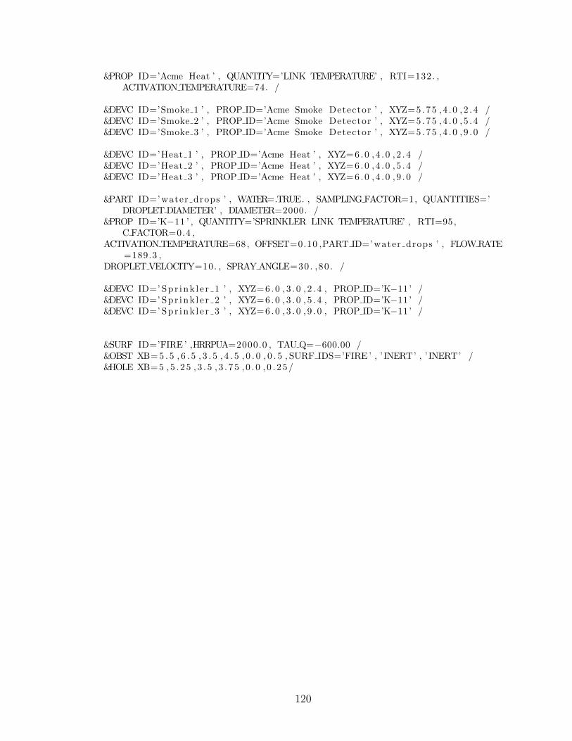
&PROP ID=’Acme Heat ’ , QUANTITY=’LINK TEMPERATURE’ , RTI=132. ,ACTIVATION TEMPERATURE=74. /
&DEVC ID=’Smoke 1 ’ , PROP ID=’Acme Smoke Detector ’ , XYZ=5 .75 , 4 . 0 , 2 . 4 /&DEVC ID=’Smoke 2 ’ , PROP ID=’Acme Smoke Detector ’ , XYZ=5 .75 , 4 . 0 , 5 . 4 /&DEVC ID=’Smoke 3 ’ , PROP ID=’Acme Smoke Detector ’ , XYZ=5 .75 , 4 . 0 , 9 . 0 /
&DEVC ID=’Heat 1 ’ , PROP ID=’Acme Heat ’ , XYZ=6 .0 , 4 . 0 , 2 . 4 /&DEVC ID=’Heat 2 ’ , PROP ID=’Acme Heat ’ , XYZ=6 .0 , 4 . 0 , 5 . 4 /&DEVC ID=’Heat 3 ’ , PROP ID=’Acme Heat ’ , XYZ=6 .0 , 4 . 0 , 9 . 0 /
&PART ID=’ water drops ’ , WATER=.TRUE. , SAMPLING FACTOR=1, QUANTITIES=’DROPLET DIAMETER’ , DIAMETER=2000. /
&PROP ID=’K−11 ’ , QUANTITY=’SPRINKLER LINK TEMPERATURE’ , RTI=95,C FACTOR=0.4 ,
ACTIVATION TEMPERATURE=68, OFFSET=0.10 ,PART ID=’ water drops ’ , FLOW RATE=189.3 ,
DROPLET VELOCITY=10. , SPRAY ANGLE=30. ,80 . /
&DEVC ID=’ Spr ink l e r 1 ’ , XYZ= 6 . 0 , 3 . 0 , 2 . 4 , PROP ID=’K−11’ /&DEVC ID=’ Spr ink l e r 2 ’ , XYZ= 6 . 0 , 3 . 0 , 5 . 4 , PROP ID=’K−11’ /&DEVC ID=’ Spr ink l e r 3 ’ , XYZ= 6 . 0 , 3 . 0 , 9 . 0 , PROP ID=’K−11’ /
&SURF ID=’FIRE ’ ,HRRPUA=2000.0 , TAU Q=−600.00 /&OBST XB= 5 . 5 , 6 . 5 , 3 . 5 , 4 . 5 , 0 . 0 , 0 . 5 , SURF IDS=’FIRE ’ , ’ INERT’ , ’ INERT’ /&HOLE XB= 5 , 5 . 2 5 , 3 . 5 , 3 . 7 5 , 0 . 0 , 0 . 2 5 /
120
Appendix FPrototype Source Code
/∗∗∗∗∗∗∗∗∗∗∗∗∗∗∗∗∗∗∗∗∗∗∗∗∗∗∗∗∗∗∗∗∗∗∗∗∗∗∗∗∗∗∗∗∗∗ . / f f a / annotat ion /AnnotationIO . java∗∗∗∗∗∗∗∗∗∗∗∗∗∗∗∗∗∗∗∗∗∗∗∗∗∗∗∗∗∗∗∗∗∗∗∗∗∗∗∗∗∗∗∗∗/package f f a . annotat ion ;
import java . awt . Polygon ;import java . i o . F i l e ;import java . i o . IOException ;import java . i o . Pr intWriter ;import java . u t i l . L i s t ;import java . u t i l . TreeMap ;import java . u t i l . regex . Matcher ;import java . u t i l . regex . Pattern ;
import javax . imageio . ImageIO ;
import org . jdom . Document ;import org . jdom . Element ;import org . jdom . JDOMException ;import org . jdom . input . SAXBuilder ;import org . jdom . output . Format ;import org . jdom . output . XMLOutputter ;
import f f a . model . Bui ld ing ;import f f a . model . Floor ;import f f a . model . SensorLayer ;import f f a . model . SensorType ;
pub l i c c l a s s AnnotationIO {
p r i v a t e s t a t i c F i l e annota t i onF i l e ( F i l e root ) {re turn new F i l e ( root , ” annotat ion ”) ;
}
p r i v a t e s t a t i c F i l e f l o o r F i l e ( F i l e root , i n t f l o o r ) {re turn new F i l e ( root , S t r ing . format (” f l o o r%d . png ” , f l o o r ) ) ;
}
pub l i c s t a t i c Bui ld ing newAnnotation ( F i l e f o l d e r ) {
121
i f ( anno ta t i onF i l e ( f o l d e r ) . e x i s t s ( ) ) {re turn importAnnotation ( f o l d e r ) ;
}
F i l e [ ] img = f o l d e r . l i s t F i l e s ( ) ;Pattern floorNum = Pattern . compi le (” f l o o r ([0−9]+) \\ . png ”) ;i n t f loorCount = 0 ;
f o r ( F i l e f : img ) {St r ing name = f . getName ( ) ;Matcher matcher = floorNum . matcher (name) ;i f ( matcher . matches ( ) ) {
i n t f l o o r = I n t e g e r . pa r s e In t ( matcher . group (1 ) ) ;i f ( f l o o r > f l oorCount ) {
f l oorCount = f l o o r ;}
}}
Bui ld ing bu i l d i ng = new Bui ld ing ( ) ;f o r ( i n t i = 0 ; i < f l oorCount ; i++) {
bu i l d in g . f l o o r s . put ( i , new Floor ( ) ) ;}
setupZoneMap ( b u i l d i ng ) ;
loadFloorImages ( bu i ld ing , f o l d e r ) ;
r e turn bu i l d i n g ;}
pub l i c s t a t i c void exportAnnotat ion ( Bui ld ing bu i ld ing , F i l e save ) {Element root = new Element (” bu i l d i ng ”) ;Document doc = new Document ( root ) ;
f o r ( I n t e g e r index : b u i l d i ng . f l o o r s . keySet ( ) ) {wr i t eF loo r ( root , index , bu i l d i ng . ge tF loor ( index ) ) ;
}
XMLOutputter out = new XMLOutputter ( Format . getPrettyFormat ( ) ) ;
t ry {out . output ( doc , new PrintWriter ( save ) ) ;
} catch ( IOException e ) {// TODO Auto−generated catch blocke . pr intStackTrace ( ) ;
}}
p r i v a t e s t a t i c void wr i t eF loo r ( Element root , I n t e g e r index , Floorf l o o r ) {
Element elem = new Element (” f l o o r ”) ;root . addContent ( elem ) ;
122

elem . addContent (new Element (” index ”) . addContent ( index . t oS t r i ng ( ) ) ) ;f o r ( SensorLayer l a y e r : f l o o r . l a y e r s . va lue s ( ) ) {
writeLayer ( elem , l a y e r ) ;}
}
p r i v a t e s t a t i c void wr i teLayer ( Element root , SensorLayer l a y e r ) {Element elem = new Element (” l a y e r ”) ;root . addContent ( elem ) ;elem . s e t A t t r i b u t e (” type ” , l a y e r . getType ( ) . name ( ) ) ;
f o r ( Zone zone : l a y e r . getZones ( ) ) {writeZone ( elem , zone ) ;
}}
p r i v a t e s t a t i c void writeZone ( Element root , Zone zone ) {Element zoneElem = new Element (” zone ”) ;zoneElem . addContent (new Element (” l a b e l ”) . setText ( zone . getLabe l ( ) ) ) ;Polygon shape = zone . getZone ( ) ;Element shapeElem = new Element (” zone ”) ;zoneElem . addContent ( shapeElem ) ;f o r ( i n t i = 0 ; i < shape . npo ints ; i++) {
shapeElem . addContent (new Element (” ver tex ”) .addContent (new Element (” x ”) . setText ( S t r ing . valueOf ( shape .
xpo int s [ i ] ) ) ) .addContent (new Element (” y ”) . setText ( S t r ing . valueOf ( shape .
ypo int s [ i ] ) ) ) ) ;}
root . addContent ( zoneElem ) ;}
@SuppressWarnings (” unchecked ”)pub l i c s t a t i c Bui ld ing importAnnotation ( F i l e f o l d e r ) {
Bui ld ing bu i l d i ng = new Bui ld ing ( ) ;bu i l d i ng . f l o o r s = new TreeMap<Integer , Floor >() ;
Document doc = n u l l ;t ry {
doc = new SAXBuilder ( ) . bu i ld ( annota t i onF i l e ( f o l d e r ) ) ;
f o r ( Element e l e : ( L i s t<Element>)doc . getRootElement ( ) .ge tChi ldren ( ) ) {
i f ( e l e . getName ( ) . equa l s (” s t a t i c ”) ) {bu i l d in g . s t a t i c I n f o . add ( r e a d S t a t i c ( e l e ) ) ;
} e l s e i f ( e l e . getName ( ) . equa l s (” f l o o r ”) ) {IndexedFloor f l o o r = readFloor ( e l e ) ;bu i l d i n g . f l o o r s . put ( f l o o r . index , f l o o r . f l o o r ) ;
} e l s e {
123
throw new UnsupportedOperationException (”Unknown XML tag : ” +e l e . getName ( ) ) ;
}}
} catch (JDOMException e ) {// TODO Auto−generated catch blocke . pr intStackTrace ( ) ;
} catch ( IOException e ) {// TODO Auto−generated catch blocke . pr intStackTrace ( ) ;
}
setupZoneMap ( b u i l d i ng ) ;
loadFloorImages ( bu i ld ing , f o l d e r ) ;
r e turn bu i l d i n g ;}
p r i v a t e s t a t i c void loadFloorImages ( Bui ld ing bu i ld ing , F i l e f o l d e r ) {f o r ( i n t i : bu i l d i ng . f l o o r s . keySet ( ) ) {
t ry {F i l e f l o o r P l a n F i l e = f l o o r F i l e ( f o l d e r , i +1) ;i f ( ! f l o o r P l a n F i l e . e x i s t s ( ) ) {
System . out . p r i n t l n (” f i l e : ” + f l o o r P l a n F i l e + ” does note x i s t ! ” ) ;
}
bu i l d in g . ge tF loor ( i ) . image = ImageIO . read ( f l o o r P l a n F i l e ) ;} catch ( Exception e ) {
System . out . p r i n t l n (” Cannot read f l o o r p lans . Fata l e r r o r ”) ;e . pr intStackTrace ( ) ;System . e x i t (0 ) ;
}}//end f o r loop
}
p r i v a t e s t a t i c void setupZoneMap ( Bui ld ing bu i l d i n g ) {bu i l d i ng . zones = new TreeMap<Str ing , Zone>() ;
f o r ( Floor f l o o r : b u i l d i ng . f l o o r s . va lue s ( ) ) {f o r ( SensorLayer l a y e r : f l o o r . l a y e r s . va lue s ( ) ) {
f o r ( Zone zone : l a y e r . getZones ( ) ) {bu i l d in g . zones . put ( zone . getLabe l ( ) , zone ) ;
}}
}}
p r i v a t e s t a t i c S t r ing r e a d S t a t i c ( Element root ) {re turn root . getTextTrim ( ) ;
}
@SuppressWarnings (” unchecked ”)
124

p r i v a t e s t a t i c IndexedFloor readFloor ( Element root ) {Floor f l o o r = new Floor ( ) ;I n t e g e r index = I n t e g e r . pa r s e In t ( root . getChi ldText (” index ”) ) ;
f o r ( Element element : ( L i s t<Element>) root . ge tChi ldren (” l a y e r ”) ) {SensorLayer l a y e r = readLayer ( element ) ;f l o o r . l a y e r s . put ( l a y e r . getType ( ) , l a y e r ) ;
}
re turn new IndexedFloor ( f l o o r , index ) ;}
@SuppressWarnings (” unchecked ”)p r i v a t e s t a t i c SensorLayer readLayer ( Element root ) {
SensorType type = SensorType . valueOf ( root . g e tAt t r ibute (” type ”) .getValue ( ) ) ;
SensorLayer l a y e r = new SensorLayer ( type ) ;
f o r ( Element element : ( L i s t<Element>) root . ge tChi ldren ( ) ) {i f ( e lement . getName ( ) . equa l s (” zone ”) ) {
l a y e r . addZone ( readZone ( element ) ) ;}
}
re turn l a y e r ;}
@SuppressWarnings (” unchecked ”)p r i v a t e s t a t i c Zone readZone ( Element root ) {
Zone zone = new Zone ( ) ;zone . s e tLabe l ( root . getChi ldText (” l a b e l ”) ) ;Polygon shape = zone . getZone ( ) ;f o r ( Element ver tex : ( L i s t<Element>) root . getChi ld (” zone ”) .
ge tChi ldren (” ver tex ”) ) {i n t x = I n t e g e r . pa r s e In t ( ver tex . getChi ldText (” x ”) ) ;i n t y = I n t e g e r . pa r s e In t ( ver tex . getChi ldText (” y ”) ) ;
shape . addPoint (x , y ) ;}
re turn zone ;}
p r i v a t e s t a t i c c l a s s IndexedFloor {Floor f l o o r ;I n t e g e r index ;
pub l i c IndexedFloor ( Floor f l o o r , I n t e g e r index ) {t h i s . f l o o r = f l o o r ;t h i s . index = index ;
}}
}
125

/∗∗∗∗∗∗∗∗∗∗∗∗∗∗∗∗∗∗∗∗∗∗∗∗∗∗∗∗∗∗∗∗∗∗∗∗∗∗∗∗∗∗∗∗∗∗ . / f f a / annotat ion /ModeChangedListener . java∗∗∗∗∗∗∗∗∗∗∗∗∗∗∗∗∗∗∗∗∗∗∗∗∗∗∗∗∗∗∗∗∗∗∗∗∗∗∗∗∗∗∗∗∗/package f f a . annotat ion ;
import f f a . model . SensorType ;
pub l i c i n t e r f a c e ModeChangedListener {pub l i c void modeChanged ( AnnotationMode mode) ;pub l i c void layerChanged ( SensorType l a y e r ) ;
}
/∗∗∗∗∗∗∗∗∗∗∗∗∗∗∗∗∗∗∗∗∗∗∗∗∗∗∗∗∗∗∗∗∗∗∗∗∗∗∗∗∗∗∗∗∗∗ . / f f a / annotat ion /AnnotationWindow . java∗∗∗∗∗∗∗∗∗∗∗∗∗∗∗∗∗∗∗∗∗∗∗∗∗∗∗∗∗∗∗∗∗∗∗∗∗∗∗∗∗∗∗∗∗/package f f a . annotat ion ;
import i n f o . c l ea r thought . layout . TableLayout ;
import java . awt . EventQueue ;import java . awt . event . ActionEvent ;import java . awt . event . Act i onL i s t ene r ;import java . i o . F i l e ;
import javax . swing . JFi leChooser ;import javax . swing . JFrame ;import javax . swing . JMenu ;import javax . swing . JMenuBar ;import javax . swing . JMenuItem ;
import f f a . model . Bui ld ing ;import f f a . u i . MapDisplay ;import f f a . u i . U t i l ;
@SuppressWarnings (” s e r i a l ”)pub l i c c l a s s AnnotationWindow extends JFrame {
p r i v a t e MapDisplay mapDisplay ;p r i v a t e AnnotationLayer aLayer ;p r i v a t e EditPanel ed i tPane l ;p r i v a t e Toolbox too lbox ;
126
// Three columns , l e f t and r i g h t are 25%, one row , f i l l s s c r e enp r i v a t e s t a t i c f i n a l double s i z e [ ] [ ] = {{ . 25 , TableLayout . FILL ,
. 25} ,{TableLayout . FILL }} ;
p r i v a t e F i l e l a s t = new F i l e (” s t a t i c I n f o ”) ;
pub l i c AnnotationWindow ( ) {}
pub l i c void initGUI ( Bui ld ing bu i l d i n g ) {getContentPane ( ) . removeAll ( ) ;U t i l . checkEDT ( ) ;/∗∗∗∗∗∗∗∗ I n i t i a l i z e Components ∗∗∗∗∗∗∗∗∗∗∗/ed i tPane l = new EditPanel ( ) ;F i l e annotat ionFolder = new F i l e (” s t a t i c I n f o ”) ;
i f ( b u i l d i ng == n u l l ) {bu i l d in g = AnnotationIO . newAnnotation ( annotat ionFolder ) ;
}
mapDisplay = new MapDisplay ( th i s , b u i l d i ng ) ;aLayer = new AnnotationLayer ( mapDisplay , ed i tPane l ) ;
too lbox = new Toolbox ( ) ;too lbox . addModeChangedListener ( aLayer ) ;
JMenuBar menuBar = new JMenuBar ( ) ;JMenu menu = new JMenu(” F i l e ”) ;menuBar . add (menu) ;JMenuItem item = new JMenuItem (” Save ”) ;menu . add ( item ) ;item . addAct ionListener (new Act ionL i s t ene r ( ) {
@Overridepub l i c void act ionPerformed ( ActionEvent e ) {
JFi leChooser chooser = new JFi leChooser ( l a s t ) ;i n t r e t = chooser . showSaveDialog ( AnnotationWindow . t h i s ) ;i f ( r e t == JFi leChooser .APPROVE OPTION) {
AnnotationIO . exportAnnotat ion ( aLayer . ge tBu i ld ing ( ) , chooser .g e t S e l e c t e d F i l e ( ) ) ;
l a s t = chooser . g e t S e l e c t e d F i l e ( ) ;}
}}) ;item = new JMenuItem (” Load ”) ;menu . add ( item ) ;item . addAct ionListener (new Act ionL i s t ene r ( ) {
@Overridepub l i c void act ionPerformed ( ActionEvent e ) {
JFi leChooser chooser = new JFi leChooser ( l a s t ) ;chooser . s e tF i l eSe l e c t i onMode ( JFi leChooser .DIRECTORIES ONLY) ;i n t r e t = chooser . showOpenDialog ( AnnotationWindow . t h i s ) ;i f ( r e t == JFi leChooser .APPROVE OPTION) {
Bui ld ing bu i l d i ng = AnnotationIO . importAnnotation ( chooser .g e t S e l e c t e d F i l e ( ) ) ;
127
s e t V i s i b l e ( f a l s e ) ;initGUI ( bu i l d i ng ) ;r epa in t ( ) ;s e t V i s i b l e ( t rue ) ;
}}
}) ;
/∗∗∗∗∗∗∗∗ I n i t i a l i z e Frame ∗∗∗∗∗∗∗∗∗∗∗/t h i s . setJMenuBar (menuBar ) ;
// I b e l i e v e t h i s i s the standard sc r e en s i z e we ’ re working witht h i s . s e t S i z e (1024 , 768) ;
// Centers the windowt h i s . s e tLocat ionRe lat iveTo ( n u l l ) ;
// This i s the main app windowsetDe fau l tC lo seOperat ion ( JFrame .EXIT ON CLOSE) ;
setLayout (new TableLayout ( s i z e ) ) ;
getContentPane ( ) . add ( mapDisplay , ”1 ,0 ,1 ,0”) ;getContentPane ( ) . add ( toolbox , ”0 ,0 ,0 ,0”) ;getContentPane ( ) . add ( editPane l , ”2 ,0 ,2 ,0”) ;
}
pub l i c void initGUI ( ) {initGUI ( n u l l ) ;
}
pub l i c s t a t i c void main ( St r ing [ ] a rgs ) {f i n a l AnnotationWindow window = new AnnotationWindow ( ) ;EventQueue . invokeLater (new Runnable ( ) {
pub l i c void run ( ) {window . initGUI ( ) ;window . s e t V i s i b l e ( t rue ) ;
}}) ;
}}
/∗∗∗∗∗∗∗∗∗∗∗∗∗∗∗∗∗∗∗∗∗∗∗∗∗∗∗∗∗∗∗∗∗∗∗∗∗∗∗∗∗∗∗∗∗∗ . / f f a / annotat ion / AnnotationLayer . java∗∗∗∗∗∗∗∗∗∗∗∗∗∗∗∗∗∗∗∗∗∗∗∗∗∗∗∗∗∗∗∗∗∗∗∗∗∗∗∗∗∗∗∗∗//∗Levon K. Mkrtchyan
128
This Component d i s p l a y s annotat ion s t u f f s andaccept s annotat ion commands∗/
package f f a . annotat ion ;
import java . awt . Color ;import java . awt . Cursor ;import java . awt . Graphics ;import java . awt . Graphics2D ;import java . awt . Polygon ;import java . awt . Rectangle ;import java . awt . event . ComponentAdapter ;import java . awt . event . ComponentEvent ;import java . awt . event . ComponentListener ;import java . awt . event . KeyAdapter ;import java . awt . event . KeyEvent ;import java . awt . event . KeyListener ;import java . awt . event . MouseAdapter ;import java . awt . event . MouseEvent ;import java . awt . geom . Aff ineTransform ;import java . awt . geom . Line2D ;import java . awt . geom . Point2D ;import java . u t i l . I t e r a t o r ;
import javax . swing . JComponent ;
import f f a . model . Bui ld ing ;import f f a . model . Floor ;import f f a . model . SensorLayer ;import f f a . model . SensorType ;import f f a . u i . MapDisplay ;
pub l i c c l a s s AnnotationLayer extends JComponent implementsModeChangedListener{
s t a t i c f i n a l long ser ia lVers ionUID = 1L ;
p r i v a t e EditPanel e d i t o r ;
p r i v a t e Zone curZone = n u l l ;p r i v a t e i n t curZoneFloor = 0 ;p r i v a t e i n t curVertex = −1;
p r i v a t e MapDisplay d i s p l a y = n u l l ;
p r i v a t e Bui ld ing b u i l d i ng ;// p r i v a t e I n t e g e r curFloor = 0 ;
p r i v a t e SensorType l a y e r = SensorType .HEAT;
p r i v a t e ComponentListener c l = new ComponentAdapter ( ) {pub l i c void componentResized ( ComponentEvent e ) {
129
AnnotationLayer . t h i s . s e t S i z e ( e . getComponent ( ) . getWidth ( ) , e .getComponent ( ) . getHeight ( ) ) ;
}} ;
p r i v a t e KeyListener k l = new KeyAdapter ( ) {pub l i c void keyTyped ( KeyEvent e ) {
i f ( e . getKeyChar ( )==KeyEvent .VK DELETE) {Zone nz = nextZone ( curZone ) ;i f ( curVertex !=−1){
de l e t eVer t ex ( curZone , curVertex ) ;curVertex−−;i f ( curVertex <0)
curVertex=curZone . getZone ( ) . npoints −1;
i f ( curZone . getZone ( ) . npo ints==0){curZone=nz ;curVertex=−1;
}} e l s e i f ( curZone != n u l l ) {
de le teZone ( curZone ) ;curZone=nz ;
}} e l s e i f ( e . getKeyChar ( )==KeyEvent .VK TAB) {
Zone nz ;i f ( e . i sShi ftDown ( ) ) {
nz = prevZone ( curZone ) ;} e l s e {
nz = nextZone ( curZone ) ;}curVertex=−1;curZone=nz ;
}d i s p l a y . r epa in t ( ) ;
}} ;
p r i v a t e MouseAdapter moveML = n u l l ;p r i v a t e MouseAdapter zoneML = new MouseAdapter ( ) {
pub l i c void mousePressed ( MouseEvent e ) {i f ( curVertex==−1){
e d i t o r . c l e a r ( ) ;curZone = new Zone ( ) ;curZoneFloor=d i s p l a y . getCurrentFloor ( ) ;g e tBu i ld ing ( ) . getLayer ( d i s p l a y . getCurrentFloor ( ) , l a y e r ) .
addZone ( curZone ) ;e d i t o r . e d i t ( curZone ) ;
}
curVertex = curZone . getZone ( ) . npo ints ;Point2D pt = d i s p l a y . screenToMap ( e . getPoint ( ) ) ;curZone . getZone ( ) . addPoint ( ( i n t ) pt . getX ( ) , ( i n t ) pt . getY ( ) ) ;
d i s p l a y . r epa in t ( ) ;
130
}
pub l i c void mouseClicked ( MouseEvent e ) {i f ( e . getCl ickCount ( )==2)
curVertex=−1;d i s p l a y . r epa in t ( ) ;
}
pub l i c void mouseDragged ( MouseEvent e ) {Polygon poly = curZone . getZone ( ) ;Point2D pt = d i s p l a y . screenToMap ( e . getPoint ( ) ) ;poly . xpo int s [ curVertex ]=( i n t ) pt . getX ( ) ;poly . ypo int s [ curVertex ]=( i n t ) pt . getY ( ) ;d i s p l a y . r epa in t ( ) ;
}} ;p r i v a t e MouseAdapter editML = new MouseAdapter ( ) {
double zoneOffsetX = 0 f ;double zoneOffsetY = 0 f ;
pub l i c void mousePressed ( MouseEvent e ) {Point2D pt = d i s p l a y . screenToMap ( e . getPoint ( ) ) ;i f ( curZone != n u l l ) {
Polygon poly = curZone . getZone ( ) ;f o r ( i n t n=0;n<poly . npo ints ; n++)
i f ( pt . d i s t anc e ( poly . xpo int s [ n ] , poly . ypo int s [ n ] ) ∗ d i s p l a y .getZoom ( )<=4){
curVertex=n ;d i s p l a y . se tCursor (new Cursor ( Cursor .MOVE CURSOR) ) ;d i s p l a y . r epa in t ( ) ;r e turn ;
}
i f (new Line2D . Double (poly . xpo int s [ poly . npoints −1] , poly . ypo int s [ poly . npoints −1] ,poly . xpo int s [ 0 ] , poly . ypo int s [ 0 ] ) . ptL ineDist ( pt )∗ d i s p l a y . getZoom ( )<=3){
poly . addPoint ( ( i n t ) pt . getX ( ) , ( i n t ) pt . getY ( ) ) ;curVertex=poly . npoints −1;d i s p l a y . se tCursor (new Cursor ( Cursor .MOVE CURSOR) ) ;d i s p l a y . r epa in t ( ) ;r e turn ;
}f o r ( i n t n=1;n<poly . npo ints ; n++)
i f (new Line2D . Double (poly . xpo int s [ n−1] , poly . ypo int s [ n−1] ,poly . xpo int s [ n ] , poly . ypo int s [ n ] ) . ptL ineDist ( pt )∗ d i s p l a y . getZoom ( )<=3){
poly . addPoint (1 , 1) ;f o r ( i n t i=poly . npoints −1; i>n ; i−−){
poly . xpo int s [ i ]= poly . xpo int s [ i −1] ;poly . ypo int s [ i ]= poly . ypo int s [ i −1] ;
}poly . xpo int s [ n ]=( i n t ) pt . getX ( ) ;
131
poly . ypo int s [ n ]=( i n t ) pt . getY ( ) ;curVertex=n ;d i s p l a y . se tCursor (new Cursor ( Cursor .MOVE CURSOR) ) ;d i s p l a y . r epa in t ( ) ;r e turn ;
}}
curZone=n u l l ;curVertex=−1;e d i t o r . c l e a r ( ) ;
SensorLayer sLayer = getBu i ld ing ( ) . getLayer ( d i s p l a y .getCurrentFloor ( ) , l a y e r ) ;
f o r ( Zone z : sLayer . getZones ( ) ) {i f ( z . getZone ( ) . conta in s ( pt ) ) {
curZone=z ;curZoneFloor=d i s p l a y . getCurrentFloor ( ) ;
Rectangle bounds = curZone . getZone ( ) . getBounds ( ) ;zoneOffsetX=pt . getX ( )−bounds . x ;zoneOffsetY=pt . getY ( )−bounds . y ;
e d i t o r . e d i t ( z ) ;d i s p l a y . se tCursor (new Cursor ( Cursor .MOVE CURSOR) ) ;d i s p l a y . r epa in t ( ) ;r e turn ;
}}d i s p l a y . r epa in t ( ) ;
}
pub l i c void mouseReleased ( MouseEvent e ) {d i s p l a y . se tCursor (new Cursor ( Cursor .DEFAULT CURSOR) ) ;
}
pub l i c void mouseDragged ( MouseEvent e ) {Point2D pt = d i s p l a y . screenToMap ( e . getPoint ( ) ) ;i f ( curZone != n u l l && curVertex==−1){
Rectangle bounds = curZone . getZone ( ) . getBounds ( ) ;curZone . getZone ( ) . t r a n s l a t e (
( i n t ) ( pt . getX ( )−zoneOffsetX−bounds . x ) ,( i n t ) ( pt . getY ( )−zoneOffsetY−bounds . y ) ) ;
d i s p l a y . r epa in t ( ) ;} e l s e i f ( curZone != n u l l && curVertex>=0){
curZone . getZone ( ) . xpo int s [ curVertex ]=( i n t ) pt . getX ( ) ;curZone . getZone ( ) . ypo int s [ curVertex ]=( i n t ) pt . getY ( ) ;d i s p l a y . r epa in t ( ) ;
}}
} ;
pub l i c void modeChanged ( AnnotationMode mode) {
132
curZone=n u l l ;e d i t o r . c l e a r ( ) ;
t h i s . removeMouseListener (moveML) ;t h i s . removeMouseMotionListener (moveML) ;t h i s . removeMouseListener (zoneML) ;t h i s . removeMouseMotionListener (zoneML) ;t h i s . removeMouseListener ( editML ) ;t h i s . removeMouseMotionListener ( editML ) ;
switch (mode) {case MOVE:
t h i s . addMouseListener (moveML) ;t h i s . addMouseMotionListener (moveML) ;t h i s . addMouseWheelListener (moveML) ;break ;
case EDIT :t h i s . addMouseListener ( editML ) ;t h i s . addMouseMotionListener ( editML ) ;break ;
case ZONE:t h i s . addMouseListener (zoneML) ;t h i s . addMouseMotionListener (zoneML) ;break ;
}
d i s p l a y . r epa in t ( ) ;}@Overridepub l i c void layerChanged ( SensorType l a y e r ) {
t h i s . l a y e r=l a y e r ;curZone=n u l l ;curVertex=−1;e d i t o r . c l e a r ( ) ;d i s p l a y . r epa in t ( ) ;
}
pub l i c AnnotationLayer ( MapDisplay d i sp lay , EditPanel e d i t o r ) {t h i s . e d i t o r = e d i t o r ;t h i s . d i s p l a y = d i s p l a y ;t h i s . setOpaque ( f a l s e ) ;d i s p l a y . add ( th i s , new I n t e g e r (1 ) ) ;moveML = d i s p l a y . mapMouseListener ;d i s p l a y . addComponentListener ( c l ) ;t h i s . setBackground (new Color (255 ,255 ,255 , Color .TRANSLUCENT) ) ;t h i s . setForeground (new Color (255 ,255 ,255 , Color .TRANSLUCENT) ) ;
s e t B u i l d i n g ( d i s p l a y . bu i l d i n g ) ;layerChanged ( SensorType .SMOKE) ;
/∗∗∗∗∗∗∗ Sample Key L i s t e n e r Code ∗∗∗∗∗∗∗∗∗/se tFocusab l e ( t rue ) ; // Component needs f o cus f o r keyssetFocusTraversalKeysEnabled ( f a l s e ) ; // Disab le tab and s h i f t−tab
133
// Request f o cus when mouse e n t e r s or when mouse i s c l i c k e d .// TODO: Not sure which o f the se two i s most appropr ia teaddMouseListener (new MouseAdapter ( ) {
@Overridepub l i c void mouseEntered ( MouseEvent e ) {
AnnotationLayer . t h i s . requestFocusInWindow ( ) ;//System . out . p r i n t l n (” h i ”) ;
}
@Overridepub l i c void mouseClicked ( MouseEvent e ) {
AnnotationLayer . t h i s . requestFocusInWindow ( ) ;//System . out . p r i n t l n (” h a l l o ”) ;
}}) ;
t h i s . addKeyListener ( k l ) ;}
pub l i c void pa int ( Graphics g ) {i f ( curZoneFloor != d i s p l a y . getCurrentFloor ( ) )
curZone=n u l l ;Graphics2D g2d = ( Graphics2D ) g ;
Aff ineTransform o r i g i n a l = g2d . getTransform ( ) ;
g2d . trans form ( d i s p l a y . getTransform ( ) ) ;
f l o a t zoom = d i s p l a y . getZoom ( ) ;
Color opaque = Color . b lack ;Color t ransparent ;switch ( l a y e r ) {case HEAT:
opaque = Color . red ;break ;
case SMOKE:opaque = Color . gray ;break ;
case FLOW:opaque = Color . b lue ;break ;
case MANUAL:opaque = Color . green ;break ;
}t ransparent = new Color ( opaque . getRed ( ) , opaque . getGreen ( ) , opaque .
getBlue ( ) ,50) ;
i f ( curZone != n u l l ) {g . s e tCo lo r ( t ransparent ) ;g . f i l l P o l y g o n ( curZone . getZone ( ) ) ;
}
134
g . s e tCo lo r ( opaque ) ;SensorLayer sLayer = getBu i ld ing ( ) . getLayer ( d i s p l a y . getCurrentFloor
( ) , l a y e r ) ;
f o r ( Zone z : sLayer . getZones ( ) ) {g . drawPolygon ( z . getZone ( ) ) ;f o r ( i n t n=0;n<z . getZone ( ) . npo ints ; n++){
g . f i l l R e c t ( z . getZone ( ) . xpo int s [ n]−( i n t ) (2/zoom) , z . getZone ( ) .ypo int s [ n]−( i n t ) (2/zoom) , ( i n t ) (5/zoom) , ( i n t ) (5/zoom) ) ;
}}
i f ( curVertex>=0){g . s e tCo lo r ( Color . b lack ) ;g . f i l l R e c t ( curZone . getZone ( ) . xpo int s [ curVertex ]−( i n t ) (2/zoom) ,
curZone . getZone ( ) . ypo int s [ curVertex ]−( i n t ) (2/zoom) , ( i n t ) (5/zoom) , ( i n t ) (5/zoom) ) ;
}
g2d . setTransform ( o r i g i n a l ) ;}/∗pub l i c void se tLayer s (Map<SensorType , SensorLayer> l a y e r s ) {
t h i s . l a y e r s = l a y e r s ;curZone = n u l l ;e d i t o r . c l e a r ( ) ;
d i s p l a y . r epa in t ( ) ;}∗/
p r i v a t e Zone prevZone ( Zone z ) {Zone r e t=n u l l ;I t e r a t o r <Zone> i t r = getBu i ld ing ( ) . getLayer ( d i s p l a y . getCurrentFloor
( ) , l a y e r ) . getZones ( ) . i t e r a t o r ( ) ;whi l e ( i t r . hasNext ( ) ) {
Zone next = i t r . next ( ) ;i f ( next==z && r e t != n u l l )
r e turn r e t ;e l s e
r e t=next ;}
i t r = getBu i ld ing ( ) . getLayer ( d i s p l a y . getCurrentFloor ( ) , l a y e r ) .getZones ( ) . i t e r a t o r ( ) ;
i f ( i t r . hasNext ( ) && i t r . next ( )==z )return r e t ;
e l s ere turn n u l l ;
}
p r i v a t e Zone nextZone ( Zone z ) {i f ( z==n u l l )
r e turn n u l l ;
135

Zone r e t=n u l l ;I t e r a t o r <Zone> i t r = getBu i ld ing ( ) . getLayer ( d i s p l a y . getCurrentFloor
( ) , l a y e r ) . getZones ( ) . i t e r a t o r ( ) ;whi l e ( i t r . hasNext ( ) ) {
i f ( r e t==z )return i t r . next ( ) ;
e l s er e t=i t r . next ( ) ;
}i f ( r e t==z )
return ge tBu i ld ing ( ) . getLayer ( d i s p l a y . getCurrentFloor ( ) , l a y e r ) .getZones ( ) . i t e r a t o r ( ) . next ( ) ;
e l s ere turn n u l l ;
}
p r i v a t e void de le teZone ( Zone z ) {ge tBu i ld ing ( ) . getLayer ( d i s p l a y . getCurrentFloor ( ) , l a y e r ) . removeZone
( z ) ;}
p r i v a t e void de l e t eVer t ex ( Zone z , i n t v ) {Polygon p = z . getZone ( ) ;i f (p . npoints<=v | | v<0)
re turn ;
i f (p . npo ints==1){p . npo ints =0;de le teZone ( z ) ;r e turn ;
}
p . npoints−−;f o r ( i n t i=v ; i<p . npo ints ; i++){
p . xpo int s [ i ]=p . xpo int s [ i +1] ;p . ypo int s [ i ]=p . ypo int s [ i +1] ;
}re turn ;
}pub l i c void s e t Bu i l d in g ( Bui ld ing bu i l d i ng ) {
t h i s . bu i l d i ng = bu i l d ing ;}pub l i c Bui ld ing ge tBu i ld ing ( ) {
re turn bu i l d i n g ;}
}
/∗∗∗∗∗∗∗∗∗∗∗∗∗∗∗∗∗∗∗∗∗∗∗∗∗∗∗∗∗∗∗∗∗∗∗∗∗∗∗∗∗∗∗∗∗∗ . / f f a / annotat ion / EditPanel . java∗
136
∗∗∗∗∗∗∗∗∗∗∗∗∗∗∗∗∗∗∗∗∗∗∗∗∗∗∗∗∗∗∗∗∗∗∗∗∗∗∗∗∗∗∗∗/package f f a . annotat ion ;
import i n f o . c l ea r thought . layout . TableLayout ;import i n f o . c l ea r thought . layout . TableLayoutConstraints ;
import java . awt . CardLayout ;import java . awt . event . ActionEvent ;import java . awt . event . Act i onL i s t ene r ;
import javax . swing . JButton ;import javax . swing . JLabel ;import javax . swing . JPanel ;import javax . swing . JTextFie ld ;
import f f a . u i . U t i l ;
@SuppressWarnings (” s e r i a l ”)pub l i c c l a s s EditPanel extends JPanel implements Act i onL i s t ene r {
p r i v a t e Zone curZone = n u l l ;
p r i v a t e CardLayout layout = new CardLayout ( ) ;
p r i v a t e JPanel zonePanel = new JPanel ( ) ;JTextFie ld zoneLabel = new JTextFie ld ( ) ;
p r i v a t e JLabel zoneName = new JLabel ( ) ;
pub l i c EditPanel ( ) {U t i l . checkEDT ( ) ;
t h i s . setLayout ( layout ) ;
add (new JPanel ( ) , ” blank ”) ;add ( zonePanel , ” zone ”) ;
zonePanel . setLayout (new TableLayout (new double [ ] [ ] {
{ . 3 , . 7 } ,{TableLayout .PREFERRED, TableLayout .PREFERRED, 15 ,
TableLayout .PREFERRED, TableLayout .PREFERRED,TableLayout .PREFERRED}
}) ) ;zonePanel . add (new JLabel (”ZONE”) , ”0 ,0 ,1 ,0”) ;zonePanel . add (new JLabel (” Label : ”) , ”0 ,1”) ;zonePanel . add ( zoneName , ”1 ,1”) ;zonePanel . add (new JLabel (” Edit zone p r o p e r t i e s ”) , ”0 ,3 ,1 ,3”) ;zonePanel . add (new JLabel (” Label : ” ) , ”0 ,4”) ;zonePanel . add ( zoneLabel , ”1 ,4”) ;
JButton zoneOk = new JButton (”OK”) ;zoneOk . setActionCommand (” zone ”) ;zoneOk . addAct ionListener ( t h i s ) ;
137
zonePanel . add ( zoneOk , new TableLayoutConstra ints ( 0 , 5 , 1 , 5 ,TableLayout .RIGHT, TableLayout .TOP) ) ;
}
pub l i c void c l e a r ( ) {curZone = n u l l ;l ayout . show ( th i s , ” blank ”) ;
}pub l i c void e d i t ( Zone zone ) {
zoneName . setText ( zone . getLabe l ( ) ) ;zoneLabel . setText ( zone . getLabe l ( ) ) ;l ayout . show ( th i s , ” zone ”) ;
curZone = zone ;}
@Overridepub l i c void act ionPerformed ( ActionEvent e ) {
i f ( e . getActionCommand ( ) . equa l s (” zone ”) ) {curZone . s e tLabe l ( zoneLabel . getText ( ) ) ;e d i t ( curZone ) ; // Refresh window
}}
}
/∗∗∗∗∗∗∗∗∗∗∗∗∗∗∗∗∗∗∗∗∗∗∗∗∗∗∗∗∗∗∗∗∗∗∗∗∗∗∗∗∗∗∗∗∗∗ . / f f a / annotat ion /Zone . java∗∗∗∗∗∗∗∗∗∗∗∗∗∗∗∗∗∗∗∗∗∗∗∗∗∗∗∗∗∗∗∗∗∗∗∗∗∗∗∗∗∗∗∗∗/package f f a . annotat ion ;
import java . awt . Polygon ;import java . u t i l . I t e r a t o r ;import java . u t i l . TreeSet ;import java . u t i l . Comparator ;import f f a . model . Event ;
import org . joda . time . DateTime ;
pub l i c c l a s s Zone {p r i v a t e Polygon zone ;p r i v a t e St r ing l a b e l ;p r i v a t e TreeSet<Event> events ; // t h i s f i e l d not used by
AnnotationLayer , i t i s only used by MetaInfoLayer in the mainv i s u a l i z a t i o n so f tware .
f i n a l s t a t i c long d i sp layDurat ion = 15000 ;
pub l i c void addEvent ( Event e ) {
138

events . add ( e ) ;}
pub l i c Zone ( ) {events = new TreeSet<Event>(new Comparator<Event>(){
pub l i c i n t compare ( Event a , Event b) {re turn a . getTime ( ) . compareTo (b . getTime ( ) ) ;
}}) ;zone = new Polygon ( ) ;
}
pub l i c i n t getOpacity ( DateTime dt ) {long s y s M i l l i s = dt . g e t M i l l i s ( ) ;Event recentEvent = n u l l ;I t e r a t o r <Event> i t r = events . d e s c e n d i n g I t e r a t o r ( ) ;whi l e ( i t r . hasNext ( ) && recentEvent==n u l l ) {
Event e = i t r . next ( ) ;i f ( s y s M i l l i s > e . getTime ( ) . getTime ( ) )
recentEvent = e ;}
i f ( recentEvent==n u l l ) // | | s y s M i l l i s−recentEvent . getTime ( ) . getTime( )>di sp layDurat ion )
re turn 0 ;
re turn 200 ;//( i n t ) ( ( d i sp layDurat ion−s y s M i l l i s+recentEvent . getTime( ) . getTime ( ) ) ∗200/ d i sp layDurat ion ) ;
}
pub l i c Polygon getZone ( ) {re turn zone ;
}
protec ted St r ing getLabe l ( ) {re turn l a b e l ;
}
protec ted void se tLabe l ( S t r ing l a b e l ) {t h i s . l a b e l = l a b e l ;
}}
/∗∗∗∗∗∗∗∗∗∗∗∗∗∗∗∗∗∗∗∗∗∗∗∗∗∗∗∗∗∗∗∗∗∗∗∗∗∗∗∗∗∗∗∗∗∗ . / f f a / annotat ion /Toolbox . java∗∗∗∗∗∗∗∗∗∗∗∗∗∗∗∗∗∗∗∗∗∗∗∗∗∗∗∗∗∗∗∗∗∗∗∗∗∗∗∗∗∗∗∗∗/package f f a . annotat ion ;
139
import i n f o . c l ea r thought . layout . TableLayout ;
import java . awt . event . ActionEvent ;import java . awt . event . Act i onL i s t ene r ;import java . u t i l . ArrayList ;import java . u t i l . L i s t ;
import javax . swing . ButtonGroup ;import javax . swing . JPanel ;import javax . swing . JToggleButton ;
import f f a . model . SensorType ;import f f a . u i . U t i l ;
@SuppressWarnings (” s e r i a l ”)pub l i c c l a s s Toolbox extends JPanel implements Act i onL i s t ene r {
p r i v a t e Lis t<ModeChangedListener> modeChangedList = n u l l ;
pub l i c Toolbox ( ) {modeChangedList = new ArrayList<ModeChangedListener >() ;U t i l . checkEDT ( ) ;setLayout (new TableLayout (new double [ ] [ ] { { TableLayout . FILL
} ,{ . 5 , . 5 }} ) ) ;
JPanel buttonPanel = new JPanel (new TableLayout (new double [ ] [ ] {
{ . 5 , . 5 } ,{TableLayout .PREFERRED, TableLayout .PREFERRED, TableLayout .
PREFERRED}}) ) ;
JPanel l aye rPane l = new JPanel ( ) ;
add ( buttonPanel , ”0 ,0”) ;add ( layerPane l , ”0 ,1”) ;
ButtonGroup toolboxGroup = new ButtonGroup ( ) ;
ToolboxButton button = new ToolboxButton ( AnnotationMode .MOVE, ” Move”) ;
button . addAct ionLis tener ( t h i s ) ;toolboxGroup . add ( button ) ;buttonPanel . add ( button , ”0 ,0”) ;button . doCl ick ( ) ; // s e l e c t s the move t o o l by d e f a u l t
button = new ToolboxButton ( AnnotationMode . EDIT, ” Edit ”) ;button . addAct ionLis tener ( t h i s ) ;toolboxGroup . add ( button ) ;buttonPanel . add ( button , ”1 ,0”) ;
button = new ToolboxButton ( AnnotationMode .ZONE, ”Zone ”) ;button . addAct ionLis tener ( t h i s ) ;toolboxGroup . add ( button ) ;buttonPanel . add ( button , ”1 ,1”) ;
140
/∗ button = new ToolboxButton ( AnnotationMode .DELETE, ” Delete ”) ;button . addAct ionLis tener ( t h i s ) ;toolboxGroup . add ( button ) ;buttonPanel . add ( button , ”1 ,2”) ;∗/
ButtonGroup layerGroup = new ButtonGroup ( ) ;f o r ( SensorType type : SensorType . va lue s ( ) ) {
LayerButton layerButton = new LayerButton ( type ) ;layerButton . addAct ionLis tener ( t h i s ) ;l aye rPane l . add ( layerButton ) ;layerGroup . add ( layerButton ) ;
}layerGroup . getElements ( ) . nextElement ( ) . doCl ick ( ) ; // s e l e c t s a l a y e r
by d e f a u l t − we don ’ t r e a l l y care which one}
pub l i c void act ionPerformed ( ActionEvent e ) {i f ( e . getSource ( ) i n s t a n c e o f ToolboxButton ) {
ToolboxButton source = ( ToolboxButton ) e . getSource ( ) ;
f o r ( ModeChangedListener l i s t e n e r : modeChangedList ) {l i s t e n e r . modeChanged ( source . getMode ( ) ) ;
}} e l s e i f ( e . getSource ( ) i n s t a n c e o f LayerButton ) {
LayerButton button = ( LayerButton ) e . getSource ( ) ;
f o r ( ModeChangedListener l i s t e n e r : modeChangedList ) {l i s t e n e r . layerChanged ( button . type ) ;
}
System . out . p r i n t l n ( button . type ) ;}
}
pub l i c void addModeChangedListener ( ModeChangedListener l ) {modeChangedList . add ( l ) ;
}
p r i v a t e c l a s s ToolboxButton extends JToggleButton{p r i v a t e AnnotationMode mode ;pub l i c ToolboxButton ( AnnotationMode mode , S t r ing text ) {
t h i s . mode = mode ;t h i s . setText ( t ex t ) ;
}
pub l i c AnnotationMode getMode ( ) {re turn mode ;
}}p r i v a t e c l a s s LayerButton extends JToggleButton {
pub l i c f i n a l SensorType type ;pub l i c LayerButton ( SensorType type ) {
t h i s . type = type ;setText ( type . t i t l e ) ;
141
}}
}
/∗∗∗∗∗∗∗∗∗∗∗∗∗∗∗∗∗∗∗∗∗∗∗∗∗∗∗∗∗∗∗∗∗∗∗∗∗∗∗∗∗∗∗∗∗∗ . / f f a / annotat ion /AnnotationMode . java∗∗∗∗∗∗∗∗∗∗∗∗∗∗∗∗∗∗∗∗∗∗∗∗∗∗∗∗∗∗∗∗∗∗∗∗∗∗∗∗∗∗∗∗∗/package f f a . annotat ion ;
pub l i c enum AnnotationMode {MOVE, EDIT, SENSOR, ZONE, LINK, DELETE;
}
/∗∗∗∗∗∗∗∗∗∗∗∗∗∗∗∗∗∗∗∗∗∗∗∗∗∗∗∗∗∗∗∗∗∗∗∗∗∗∗∗∗∗∗∗∗∗ . / f f a /model/ Sensor . java∗∗∗∗∗∗∗∗∗∗∗∗∗∗∗∗∗∗∗∗∗∗∗∗∗∗∗∗∗∗∗∗∗∗∗∗∗∗∗∗∗∗∗∗∗/package f f a . model ;
/∗∗∗ @author jwu∗∗/
pub l i c ab s t r a c t c l a s s Sensor {St r ing ID = ”” ;Locat ion l o c a t i o n = n u l l ;
boolean alarm = f a l s e ;boolean t roub l e = f a l s e ;
pub l i c Sensor ( Locat ion l o c a t i o n ) {super ( ) ;t h i s . l o c a t i o n = l o c a t i o n ;
}pub l i c Sensor ( S t r ing id ){
super ( ) ;t h i s . ID = id ;
}pub l i c Sensor ( Locat ion loc , S t r ing id ){
super ( ) ;
142
t h i s . l o c a t i o n = l o c ;t h i s . ID = id ;
}
pub l i c boolean inAlarm ( ){
re turn alarm ;}
pub l i c S t r ing getID ( ){
re turn ID ;}pub l i c boolean inTrouble ( ){
re turn t roub l e ;}
pub l i c void setAlarm ( boolean s t a t u s ){
t h i s . alarm = s t a t u s ;}
pub l i c void setTrouble ( boolean s t a t u s ){
t h i s . alarm = troub l e ;}
}
/∗∗∗∗∗∗∗∗∗∗∗∗∗∗∗∗∗∗∗∗∗∗∗∗∗∗∗∗∗∗∗∗∗∗∗∗∗∗∗∗∗∗∗∗∗∗ . / f f a /model/RS232Demo . java∗∗∗∗∗∗∗∗∗∗∗∗∗∗∗∗∗∗∗∗∗∗∗∗∗∗∗∗∗∗∗∗∗∗∗∗∗∗∗∗∗∗∗∗∗/package f f a . model ;
import java . i o . ∗ ;import gnu . i o . ∗ ;
/∗ Demo o f input from RS232 . This r e q u i r e s a proper implementation∗ o f the javax .comm l i b r a r y f o r a g iven opera t ing system . The∗ one c u r r e n t l y used i s the Windows vers ion , found in RXTXcomm. j a r∗/
pub l i c c l a s s RS232Demo {
pub l i c s t a t i c void main ( St r ing [ ] a rgs ){
CommPortIdenti f ier ident = n u l l ;S t r ing portName = ”COM3” ;
143
i f ( a rgs . l ength > 0)portName = args [ 0 ] ;
t ry {i dent = CommPortIdenti f ier . g e t P o r t I d e n t i f i e r ( portName ) ;
}catch ( NoSuchPortException e ){
System . e r r . p r i n t l n (”No such port : ” + portName ) ;System . e x i t (0 ) ;
}i f ( ident == n u l l | | i dent . isCurrentlyOwned ( ) ){
System . e r r . p r i n t l n (” Port ” + portName + ” in use ”) ;System . e x i t (0 ) ;
}e l s e{
t ry {CommPort commPort = ident . open (”Demo” , 2000) ;
i f ( commPort i n s t a n c e o f S e r i a l P o r t ){
S e r i a l P o r t s e r i a l P o r t = ( S e r i a l P o r t ) commPort ;s e r i a l P o r t . s e tSer ia lPortParams (2400 , S e r i a l P o r t . DATABITS 7
, S e r i a l P o r t . STOPBITS 1 , S e r i a l P o r t .PARITY EVEN) ;
InputStream in = s e r i a l P o r t . getInputStream ( ) ;
s e r i a l P o r t . addEventListener (new Ser ia lReader ( in ) ) ;s e r i a l P o r t . not i fyOnDataAvai lable ( t rue ) ;
}e l s e{
System . out . p r i n t l n (” Error : Only s e r i a l por t s are handledby t h i s example . ” ) ;
}}catch ( Exception e ){
e . pr intStackTrace ( ) ;}
}
}pub l i c s t a t i c c l a s s Se r i a lReader implements Se r i a lPo r tEventL i s t ene r{
p r i v a t e InputStream in ;p r i v a t e byte [ ] b u f f e r = new byte [ 1 0 2 4 ] ;
pub l i c Se r i a lReader ( InputStream in ){
t h i s . in = in ;}
144
pub l i c void s e r i a l E v e n t ( Ser ia lPortEvent arg0 ) {i n t data ;S t r ing message ;
t ry{
i n t l en = 0 ;whi l e ( ( data = in . read ( ) ) > −1 ){
i f ( data == ’\n ’ ) {break ;
}b u f f e r [ l en++] = ( byte ) data ;
}
message = par s eS t r i ng (new St r ing ( bu f f e r , 0 , l en ) ) ;i f ( message != n u l l )
System . out . p r i n t l n (”ALERT: ” + message ) ;}catch ( IOException e ){
e . pr intStackTrace ( ) ;System . e x i t (−1) ;
}}pub l i c S t r ing pa r s eS t r i ng ( S t r ing input ){
St r ing s t r = n u l l ;S t r ing [ ] inputArray ;
inputArray = input . s p l i t (”\\ s +”, 7) ;
i f ( inputArray [ 0 ] . equa l s (”ALARM: ” ) ){
s t r = inputArray [ 1 ] + ” alarm with ID : ” + inputArray [ 2 ] +” in zone ” + inputArray [ 3 ] + ” went o f f at ” +
inputArray [ 4 ] +” on ” + inputArray [ 5 ] . s u b s t r i ng (0 , 2 ) + ”/” +inputArray [ 5 ] . s ub s t r i n g (2 , 4 ) + ”/” + inputArray [ 5 ] .
s ub s t r i n g (4 , 6 ) ;}e l s e i f ( inputArray [ 0 ] . equa l s (”TROUBL”) ){
i f ( inputArray . l ength == 7)s t r = ”System in t roub l e at ” + inputArray [ 4 ] +
” on ” + inputArray [ 5 ] . s u b s t r i ng (0 , 2 ) + ”/” +inputArray [ 5 ] . s ub s t r i n g (2 , 4 ) + ”/” + inputArray [ 5 ] .
s ub s t r i n g (4 , 6 ) ;e l s e i f ( inputArray . l ength == 6)
s t r = ”System in t roub l e on ” + inputArray [ 4 ] . s u b s t r i ng(0 , 2 ) + ”/” +
inputArray [ 4 ] . s ub s t r i n g (2 , 4 ) + ”/” + inputArray [ 4 ] .s ub s t r i n g (4 , 6 ) ;
145
e l s e i f ( inputArray . l ength < 4){
s t r = ”System in t roub l e ” ;}
}re turn s t r ;
}}
}
/∗∗∗∗∗∗∗∗∗∗∗∗∗∗∗∗∗∗∗∗∗∗∗∗∗∗∗∗∗∗∗∗∗∗∗∗∗∗∗∗∗∗∗∗∗∗ . / f f a /model/ F i r e F i l t e r . java∗∗∗∗∗∗∗∗∗∗∗∗∗∗∗∗∗∗∗∗∗∗∗∗∗∗∗∗∗∗∗∗∗∗∗∗∗∗∗∗∗∗∗∗∗/package f f a . model ;
/∗ I n t e r f a c e f o r f i r e f i l t e r s . This d e c l a r e s only the g e n e r i c∗ f i l t e r ( ) method , which does the p r e p r o c e s s i n g with help∗ from i n t e r n a l v a r i a b l e s .∗/
pub l i c i n t e r f a c e F i r e F i l t e r{
pub l i c Ale r t f i l t e r ( Event e ) ;}
/∗∗∗∗∗∗∗∗∗∗∗∗∗∗∗∗∗∗∗∗∗∗∗∗∗∗∗∗∗∗∗∗∗∗∗∗∗∗∗∗∗∗∗∗∗∗ . / f f a /model/BACNetPluginRip . java∗∗∗∗∗∗∗∗∗∗∗∗∗∗∗∗∗∗∗∗∗∗∗∗∗∗∗∗∗∗∗∗∗∗∗∗∗∗∗∗∗∗∗∗∗//∗∗
============================================================================
∗ GNU Lesse r General Publ ic L i cense∗
============================================================================
∗∗ Copyright (C) 2006−2009 Seroton in Software Techno log ie s Inc . http ://
s e r o t o n i n s o f t w a r e . com∗ @author Matthew Lohbih le r∗∗ This l i b r a r y i s f r e e so f tware ; you can r e d i s t r i b u t e i t and/ or
146
∗ modify i t under the terms o f the GNU Lesse r General Publ ic∗ License as pub l i shed by the Free Software Foundation ; e i t h e r∗ v e r s i on 2 .1 o f the License , or ( at your opt ion ) any l a t e r v e r s i on .∗∗ This l i b r a r y i s d i s t r i b u t e d in the hope that i t w i l l be u se fu l ,∗ but WITHOUT ANY WARRANTY; without even the impl i ed warranty o f∗ MERCHANTABILITY or FITNESS FOR A PARTICULAR PURPOSE. See the GNU∗ Les se r General Publ ic L i cense f o r more d e t a i l s .∗∗ You should have r e c e i v e d a copy o f the GNU Lesse r General Publ ic∗ License along with t h i s l i b r a r y ; i f not , wr i t e to the Free Software∗ Foundation , Inc . , 59 Temple Place , Su i t e 330 , Boston , MA
02111−1307 , USA.∗/
package f f a . model ;
import java . i o . IOException ;import java . u t i l . ArrayList ;import java . u t i l . L i s t ;import java . u t i l .Map;import java . u t i l . Set ;import java . u t i l . TreeMap ;import java . u t i l . TreeSet ;
import com . s e r o t o n i n . bacnet4 j . LocalDevice ;import com . s e r o t o n i n . bacnet4 j . RemoteDevice ;import com . s e r o t o n i n . bacnet4 j . RemoteObject ;import com . s e r o t o n i n . bacnet4 j . event . DeviceEventLis tener ;import com . s e r o t o n i n . bacnet4 j . except ion . BACnetException ;import com . s e r o t o n i n . bacnet4 j . obj . BACnetObject ;import com . s e r o t o n i n . bacnet4 j . s e r v i c e . conf irmed .
R e i n i t i a l i z e D e v i c e R e q u e s t . R e i n i t i a l i z e d S t a t e O f D e v i c e ;import com . s e r o t o n i n . bacnet4 j . s e r v i c e . unconfirmed . WhoIsRequest ;import com . s e r o t o n i n . bacnet4 j . type . Encodable ;import com . s e r o t o n i n . bacnet4 j . type . cons t ruc ted . Choice ;import com . s e r o t o n i n . bacnet4 j . type . cons t ruc ted . ObjectPropertyReference ;import com . s e r o t o n i n . bacnet4 j . type . cons t ruc ted . PropertyValue ;import com . s e r o t o n i n . bacnet4 j . type . cons t ruc ted . SequenceOf ;import com . s e r o t o n i n . bacnet4 j . type . cons t ruc ted . TimeStamp ;import com . s e r o t o n i n . bacnet4 j . type . enumerated . EventState ;import com . s e r o t o n i n . bacnet4 j . type . enumerated . EventType ;import com . s e r o t o n i n . bacnet4 j . type . enumerated . MessagePr ior i ty ;import com . s e r o t o n i n . bacnet4 j . type . enumerated . NotifyType ;import com . s e r o t o n i n . bacnet4 j . type . enumerated . P r o p e r t y I d e n t i f i e r ;import com . s e r o t o n i n . bacnet4 j . type . n o t i f i c a t i o n P a r a m e t e r s .
Not i f i c a t i onParamete r s ;import com . s e r o t o n i n . bacnet4 j . type . p r i m i t i v e . Boolean ;import com . s e r o t o n i n . bacnet4 j . type . p r i m i t i v e . Characte rStr ing ;import com . s e r o t o n i n . bacnet4 j . type . p r i m i t i v e . O b j e c t I d e n t i f i e r ;import com . s e r o t o n i n . bacnet4 j . type . p r i m i t i v e . Uns ignedInteger ;import com . s e r o t o n i n . bacnet4 j . u t i l . PropertyReferences ;import com . s e r o t o n i n . bacnet4 j . u t i l . PropertyValues ;
/∗∗
147
∗ Discover s and d e v i c e s and p r i n t a l l p r o p e r t i e s o f a l l o b j e c t s found .∗ t h i s i s done by us ing P r o p e r t y I d e n t i f i e r . a l l so the Device w i l l send
a l l proper tys that are s e t .∗ i f you want p o l l a l l PropertyId {@link ReadPropertyRangeTest } .∗∗ @author Matthew Lohbih le r∗ @author Arne P l s e∗/
pub l i c c l a s s BACNetPluginRip {pub l i c s t a t i c S t r ing BROADCAST ADDRESS = ” 1 9 2 . 1 6 8 . 1 . 2 5 5 ” ;
/ / ” 1 2 7 . 0 . 0 . 2 5 5 ” ;p r i v a t e LoopDevice loopDevice ;p r i v a t e f i n a l LocalDevice l o c a l D e v i c e ;// remote de v i c e s foundp r i v a t e f i n a l L i s t<RemoteDevice> remoteDevices = new ArrayList<
RemoteDevice >() ;
//maps d e v i c e s to s t a t e sp r i v a t e Map<RemoteDevice , Str ing> deviceMap = new TreeMap<
RemoteDevice , Str ing >() ;
pub l i c BACNetPluginRip ( St r ing broadcastAddress , i n t port ) throwsIOException {l o c a l D e v i c e = new LocalDevice (1 , broadcastAddress ) ;
l o c a l D e v i c e . s e tPort ( port ) ;l o c a l D e v i c e . getEventHandler ( ) . addLis tener (new
DeviceEventLis tener ( ) {
pub l i c void l i s t e n e r E x c e p t i o n ( Throwable e ) {System . out . p r i n t l n (” DiscoveryTest l i s t e n e r E x c e p t i o n ”) ;
}
pub l i c void iAmReceived ( RemoteDevice d) {System . out . p r i n t l n (” DiscoveryTest iAmReceived ! ” ) ;remoteDevices . add (d) ;synchronized ( BACNetPluginRip . t h i s ) {
BACNetPluginRip . t h i s . n o t i f y A l l ( ) ;}
}
pub l i c boolean al lowPropertyWrite ( BACnetObject obj ,PropertyValue pv ) {System . out . p r i n t l n (” DiscoveryTest a l lowPropertyWrite ”) ;r e turn true ;
}
pub l i c void propertyWritten ( BACnetObject obj , PropertyValuepv ) {System . out . p r i n t l n (” DiscoveryTest propertyWritten ”) ;
}
pub l i c void iHaveReceived ( RemoteDevice d , RemoteObject o ) {System . out . p r i n t l n (” DiscoveryTest iHaveReceived ”) ;
148
}
pub l i c void covNot i f i c a t i onRece i v ed ( Uns ignedIntegers u b s c r i b e r P r o c e s s I d e n t i f i e r , RemoteDevicei n i t i a t i n g D e v i c e , O b j e c t I d e n t i f i e rmon i to r edObj e c t Iden t i f i e r , Uns ignedIntegertimeRemaining , SequenceOf<PropertyValue> l i s t O f V a l u e s ){System . out . p r i n t l n (” DiscoveryTest
covNot i f i c a t i onRece i v ed ”) ;}
pub l i c void e ven tNo t i f i c a t i onR ece i v e d ( Uns ignedIntegerp r o c e s s I d e n t i f i e r , RemoteDevice i n i t i a t i n g D e v i c e ,O b j e c t I d e n t i f i e r e v e n t O b j e c t I d e n t i f i e r , TimeStamptimeStamp , Uns ignedInteger n o t i f i c a t i o n C l a s s ,Uns ignedInteger p r i o r i t y , EventType eventType ,Characte rStr ing messageText , NotifyType notifyType ,Boolean ackRequired , EventState fromState , EventStatetoState , Not i f i c a t i onParamete r s eventValues ) {
System . out . p r i n t l n (” BACNetPluginev en t No t i f i c a t i o nRe ce i v e d : ID=” + p r o c e s s I d e n t i f i e r .longValue ( ) + ” EventType= ” + eventType . t oS t r i ng ( ) +” fromState=” + fromState . TYPE ID + ” toState= ” +
toState . TYPE ID) ;
}
pub l i c void textMessageReceived ( RemoteDevicetextMessageSourceDevice , Choice messageClass ,MessagePr ior i ty messagePr ior i ty , Characte rStr ingmessage ) {System . out . p r i n t l n (” DiscoveryTest textMessageReceived ”)
;}
pub l i c void pr iva teTrans f e rRece ived ( Uns ignedIntegervendorId , Uns ignedInteger serviceNumber , Encodablese rv i c eParamete r s ) {System . out . p r i n t l n (” DiscoveryTest
pr iva teTrans f e rRece ived ”) ;}
@Overridepub l i c void r e i n i t i a l i z e D e v i c e ( R e i n i t i a l i z e d S t a t e O f D e v i c e arg0 ) {
// TODO Auto−generated method stub
}}) ;l o c a l D e v i c e . i n i t i a l i z e ( ) ;
}
/∗∗
149
∗ Send a WhoIs r eque s t and wait f o r the f i r s t to answer∗ @throws java . lang . Exception∗/
pub l i c void doDiscover ( ) throws Exception {// Who i sSystem . out . p r i n t l n (” Send Broadcast WhoIsRequest ( ) ”) ;// Send the broadcast to the c o r r e c t port o f the LoopDevice ! ! !// l o c a l D e v i c e . sendBroadcast ( loopDevice . getPort ( ) , new
WhoIsRequest ( nu l l , n u l l ) ) ;
l o c a l D e v i c e . sendBroadcast (47808 , new WhoIsRequest ( nu l l , n u l l ) ) ;
// wait f o r n o t i f i c a t i o n in iAmReceived ( ) Timeout 5 secsynchron ized ( t h i s ) {
f i n a l long s t a r t = System . cur rentT imeMi l l i s ( ) ;t h i s . wait (5000) ;System . out . p r i n t l n (” waited f o r iAmReceived : ” + ( System .
cur rentT imeMi l l i s ( ) − s t a r t ) + ” ms”) ;}
// An other way to get to the l i s t o f d e v i c e s// return l o c a l D e v i c e . getRemoteDevices ( ) ;
}
@SuppressWarnings (” unchecked ”)p r i v a t e void pr in tDev i c e s ( ) throws BACnetException {
f o r ( RemoteDevice d : remoteDevices ) {
l o c a l D e v i c e . getExtendedDeviceInformation (d) ;
L i s t<O b j e c t I d e n t i f i e r > o id s = ( ( SequenceOf<O b j e c t I d e n t i f i e r>) l o c a l D e v i c e . sendReadPropertyAllowNull (
d , d . g e t O b j e c t I d e n t i f i e r ( ) , P r o p e r t y I d e n t i f i e r .o b j e c t L i s t ) ) . getValues ( ) ;
//xxx (10/19)System . out . p r i n t l n (” removeDevice : ” + d) ;
// and now from a l l o b j e c t s under the dev i c e ob j e c t >> ai0 ,ai1 , bi0 , b i1 . . .
f o r ( O b j e c t I d e n t i f i e r o id : o id s ) {PropertyReferences r e f s = new PropertyReferences ( ) ;
// add the property r e f e r e n c e s o f the ” dev i c e ob j e c t ”to the l i s t
r e f s . add (d . g e t O b j e c t I d e n t i f i e r ( ) , P r o p e r t y I d e n t i f i e r .a l l ) ;
r e f s . add ( oid , P r o p e r t y I d e n t i f i e r . a l l ) ;
System . out . p r i n t l n (” Star t read p r o p e r t i e s ”) ;f i n a l long s t a r t = System . cur rentT imeMi l l i s ( ) ;
150
System . out . p r i n t l n (”JWU: r e f s = ” + r e f s . s i z e ( ) ) ; //xxx
PropertyValues pvs = l o c a l D e v i c e . r eadPrope r t i e s (d , r e f s ) ;System . out . p r i n t l n ( S t r ing . format (” P r o p e r t i e s read done in
%d ms” , System . cur r entT imeMi l l i s ( ) − s t a r t ) ) ;S t r ing temp =pr intObjec t (d . g e t O b j e c t I d e n t i f i e r ( ) , pvs ) ;
System . out . p r i n t l n (” pr in t1 : ” + temp ) ;
temp = pr intObjec t ( oid , pvs ) ;System . out . p r i n t l n (” pr in t2 : ” + temp ) ;
}}
System . out . p r i n t l n (” Remote de v i c e s done . . . ” ) ;}
//xxx − hacked to re turn s t a t e (10/19)p r i v a t e St r ing pr intObjec t ( O b j e c t I d e n t i f i e r oid , PropertyValues pvs
) {System . out . p r i n t l n ( S t r ing . format (”\ t%s ” , o id ) ) ;
Set<Str ing> t e s t i n g = new TreeSet<Str ing >() ;t e s t i n g . add (” Object i d e n t i f i e r ”) ;t e s t i n g . add (” Object type ”) ;t e s t i n g . add (” Object name”) ;t e s t i n g . add (” s t a t e ”) ;t e s t i n g . add (” value ”) ;S t r ing temp ;
f o r ( ObjectPropertyReference opr : pvs ) {
// i f ( o id . equa l s ( opr . g e t O b j e c t I d e n t i f i e r ( ) ) ) {// System . out . p r i n t l n ( S t r ing . format (”\ t \ t%s = %s ” , opr .
g e t P r o p e r t y I d e n t i f i e r ( ) . t oS t r i ng ( ) , pvs . getNoErrorCheck ( opr ) ) ) ;// }
temp = opr . g e t P r o p e r t y I d e n t i f i e r ( ) . t oS t r i ng ( ) ;f o r ( S t r ing s : t e s t i n g ) {
i f ( temp . conta in s ( s ) )System . out . p r i n t l n ( S t r ing . format (”\ t \ t%s = %s ” , opr .
g e t P r o p e r t y I d e n t i f i e r ( ) . t oS t r i ng ( ) , pvs .getNoErrorCheck ( opr ) ) ) ;
i f ( temp . conta in s (” s t a t e ”) )re turn pvs . getNoErrorCheck ( opr ) . t oS t r i ng ( ) ;
}}
re turn ”No State ” ;}
/∗∗∗ Note same Bropadcast address , but d i f f e r e n t por t s ! ! !∗ @param args
151
∗ @throws java . lang . Exception∗/
@SuppressWarnings (” unchecked ”)pub l i c s t a t i c void main ( St r ing [ ] a rgs ) throws Exception {
BACNetPluginRip dt = new BACNetPluginRip (BROADCAST ADDRESS,47808) ;
t ry {dt . setLoopDevice (new LoopDevice (BROADCAST ADDRESS, 47808 +
1) ) ;} catch ( RuntimeException e ) {
dt . l o c a l D e v i c e . terminate ( ) ;throw e ;
}// try {
dt . doDiscover ( ) ;dt . p r in tDev i c e s ( ) ;
// } f i n a l l y {// dt . l o c a l D e v i c e . terminate ( ) ;// System . out . p r i n t l n (” Cleanup loopDevice ”) ;// dt . getLoopDevice ( ) . doTerminate ( ) ;// }
whi le ( t rue ) {
}}
/∗∗∗ @return the loopDevice∗/
pub l i c LoopDevice getLoopDevice ( ) {re turn loopDevice ;
}
/∗∗∗ @param loopDevice the loopDevice to s e t∗/
pub l i c void setLoopDevice ( LoopDevice loopDevice ) {t h i s . loopDevice = loopDevice ;
}}
/∗∗∗∗∗∗∗∗∗∗∗∗∗∗∗∗∗∗∗∗∗∗∗∗∗∗∗∗∗∗∗∗∗∗∗∗∗∗∗∗∗∗∗∗∗∗ . / f f a /model/ SensorLayer . java∗∗∗∗∗∗∗∗∗∗∗∗∗∗∗∗∗∗∗∗∗∗∗∗∗∗∗∗∗∗∗∗∗∗∗∗∗∗∗∗∗∗∗∗∗/package f f a . model ;
import java . u t i l . Comparator ;import java . u t i l . TreeSet ;
152
import java . u t i l . C o l l e c t i o n ;import java . awt . Rectangle ;
import f f a . annotat ion . Zone ;
pub l i c c l a s s SensorLayer {p r i v a t e SensorType type ;p r i v a t e Co l l e c t i on<Zone> zoneL i s t ;
pub l i c SensorLayer ( SensorType type ) {t h i s . type = type ;zoneL i s t = new TreeSet<Zone>(new Comparator<Zone>(){
pub l i c i n t compare ( Zone a , Zone b) {Rectangle aBounds = a . getZone ( ) . getBounds ( ) ;Rectangle bBounds = b . getZone ( ) . getBounds ( ) ;
i n t aCenterX = aBounds . x+aBounds . width /2 ;i n t aCenterY = aBounds . y+aBounds . he ight /2 ;
i n t bCenterX = bBounds . x+bBounds . width /2 ;i n t bCenterY = bBounds . y+bBounds . he ight /2 ;
i f ( ( bCenterX>aCenterX ) && ( bCenterY>aBounds . y ) )re turn −1;
i f ( ( bCenterX<aCenterX ) && ( bBounds . y<aCenterY ) )re turn 1 ;
i f ( aCenterY<bCenterY )return −1;
i f ( aCenterY>bCenterY )return 1 ;
re turn new I n t e g e r ( bCenterX ) . compareTo (new I n t e g e r ( aCenterX ) ) ;}
}) ;}
pub l i c void addZone ( Zone zone ) {zoneL i s t . add ( zone ) ;
}
pub l i c void removeZone ( Zone zone ) {zoneL i s t . remove ( zone ) ;
}
pub l i c I t e r a b l e <Zone> getZones ( ) {re turn zoneL i s t ;
}pub l i c SensorType getType ( ) {
re turn type ;}
}
153
/∗∗∗∗∗∗∗∗∗∗∗∗∗∗∗∗∗∗∗∗∗∗∗∗∗∗∗∗∗∗∗∗∗∗∗∗∗∗∗∗∗∗∗∗∗∗ . / f f a /model/LoopDevice . java∗∗∗∗∗∗∗∗∗∗∗∗∗∗∗∗∗∗∗∗∗∗∗∗∗∗∗∗∗∗∗∗∗∗∗∗∗∗∗∗∗∗∗∗∗//∗∗
============================================================================
∗ GNU Lesse r General Publ ic L i cense∗
============================================================================
∗∗ Copyright (C) 2006−2009 Seroton in Software Techno log ie s Inc . http ://
s e r o t o n i n s o f t w a r e . com∗ @author Matthew Lohbih le r∗∗ This l i b r a r y i s f r e e so f tware ; you can r e d i s t r i b u t e i t and/ or∗ modify i t under the terms o f the GNU Lesse r General Publ ic∗ License as pub l i shed by the Free Software Foundation ; e i t h e r∗ v e r s i on 2 .1 o f the License , or ( at your opt ion ) any l a t e r v e r s i on .∗∗ This l i b r a r y i s d i s t r i b u t e d in the hope that i t w i l l be u se fu l ,∗ but WITHOUT ANY WARRANTY; without even the impl i ed warranty o f∗ MERCHANTABILITY or FITNESS FOR A PARTICULAR PURPOSE. See the GNU∗ Les se r General Publ ic L i cense f o r more d e t a i l s .∗∗ You should have r e c e i v e d a copy o f the GNU Lesse r General Publ ic∗ License along with t h i s l i b r a r y ; i f not , wr i t e to the Free Software∗ Foundation , Inc . , 59 Temple Place , Su i t e 330 , Boston , MA
02111−1307 , USA.∗/
package f f a . model ;
import java . i o . IOException ;
import com . s e r o t o n i n . bacnet4 j . LocalDevice ;import com . s e r o t o n i n . bacnet4 j . RemoteDevice ;import com . s e r o t o n i n . bacnet4 j . RemoteObject ;import com . s e r o t o n i n . bacnet4 j . event . DeviceEventLis tener ;import com . s e r o t o n i n . bacnet4 j . except ion . BACnetServiceException ;import com . s e r o t o n i n . bacnet4 j . obj . BACnetObject ;import com . s e r o t o n i n . bacnet4 j . s e r v i c e . conf irmed .
R e i n i t i a l i z e D e v i c e R e q u e s t . R e i n i t i a l i z e d S t a t e O f D e v i c e ;import com . s e r o t o n i n . bacnet4 j . type . Encodable ;import com . s e r o t o n i n . bacnet4 j . type . cons t ruc ted . Choice ;import com . s e r o t o n i n . bacnet4 j . type . cons t ruc ted . PropertyValue ;import com . s e r o t o n i n . bacnet4 j . type . cons t ruc ted . SequenceOf ;
154
import com . s e r o t o n i n . bacnet4 j . type . cons t ruc ted . TimeStamp ;import com . s e r o t o n i n . bacnet4 j . type . enumerated . BinaryPV ;import com . s e r o t o n i n . bacnet4 j . type . enumerated . Eng ineer ingUnit s ;import com . s e r o t o n i n . bacnet4 j . type . enumerated . EventState ;import com . s e r o t o n i n . bacnet4 j . type . enumerated . EventType ;import com . s e r o t o n i n . bacnet4 j . type . enumerated . MessagePr ior i ty ;import com . s e r o t o n i n . bacnet4 j . type . enumerated . NotifyType ;import com . s e r o t o n i n . bacnet4 j . type . enumerated . ObjectType ;import com . s e r o t o n i n . bacnet4 j . type . enumerated . P r o p e r t y I d e n t i f i e r ;import com . s e r o t o n i n . bacnet4 j . type . enumerated . R e l i a b i l i t y ;import com . s e r o t o n i n . bacnet4 j . type . n o t i f i c a t i o n P a r a m e t e r s .
Not i f i c a t i onParamete r s ;import com . s e r o t o n i n . bacnet4 j . type . p r i m i t i v e . Boolean ;import com . s e r o t o n i n . bacnet4 j . type . p r i m i t i v e . Characte rStr ing ;import com . s e r o t o n i n . bacnet4 j . type . p r i m i t i v e . O b j e c t I d e n t i f i e r ;import com . s e r o t o n i n . bacnet4 j . type . p r i m i t i v e . Real ;import com . s e r o t o n i n . bacnet4 j . type . p r i m i t i v e . Uns ignedInteger ;
/∗∗∗∗ so f tware only dev i c e d e f a u l t l o c a l loop ;−)∗∗ @author mlohbih le r∗ @author ap l o e s e∗/
pub l i c c l a s s LoopDevice implements Runnable {
pub l i c s t a t i c void main ( St r ing [ ] a rgs ) throws Exception {LoopDevice ld = new LoopDevice ( ” 1 2 7 . 0 . 0 . 2 5 5 ” , LocalDevice .
DEFAULT PORT + 1) ;Thread . s l e e p (12000) ; // wait 2 minld . doTerminate ( ) ;
}
p r i v a t e boolean terminate ;p r i v a t e LocalDevice l o c a l D e v i c e ;p r i v a t e BACnetObject a i0 ;p r i v a t e BACnetObject a i1 ;p r i v a t e BACnetObject b i0 ;p r i v a t e BACnetObject b i1 ;p r i v a t e BACnetObject mso0 ;p r i v a t e BACnetObject ao0 ;
pub l i c LoopDevice ( S t r ing broadcastAddress , i n t port ) throwsBACnetServiceException , IOException {l o c a l D e v i c e = new LocalDevice (1968 , broadcastAddress ) ;t ry {
l o c a l D e v i c e . s e tPort ( port ) ;l o c a l D e v i c e . getEventHandler ( ) . addLis tener (new
DeviceEventLis tener ( ) {
pub l i c void l i s t e n e r E x c e p t i o n ( Throwable e ) {System . out . p r i n t l n (” loopDevice l i s t e n e r E x c e p t i o n ”) ;
}
155
pub l i c void iAmReceived ( RemoteDevice d) {System . out . p r i n t l n (” loopDevice iAmReceived ”) ;
}
pub l i c boolean al lowPropertyWrite ( BACnetObject obj ,PropertyValue pv ) {System . out . p r i n t l n (” loopDevice al lowPropertyWrite ”)
;r e turn true ;
}
pub l i c void propertyWritten ( BACnetObject obj ,PropertyValue pv ) {System . out . p r i n t l n (” loopDevice propertyWritten ”) ;
}
pub l i c void iHaveReceived ( RemoteDevice d , RemoteObjecto ) {System . out . p r i n t l n (” loopDevice iHaveReceived ”) ;
}
pub l i c void covNot i f i c a t i onRece i v ed ( Uns ignedIntegers u b s c r i b e r P r o c e s s I d e n t i f i e r , RemoteDevicei n i t i a t i n g D e v i c e , O b j e c t I d e n t i f i e rmon i to r edObj e c t Iden t i f i e r , Uns ignedIntegertimeRemaining , SequenceOf<PropertyValue>l i s t O f V a l u e s ) {System . out . p r i n t l n (” loopDevice
covNot i f i c a t i onRece i v ed ”) ;}
pub l i c void e ven tNo t i f i c a t i o nR ece i v e d ( Uns ignedIntegerp r o c e s s I d e n t i f i e r , RemoteDevice i n i t i a t i n g D e v i c e ,O b j e c t I d e n t i f i e r e v e n t O b j e c t I d e n t i f i e r , TimeStamptimeStamp , Uns ignedInteger n o t i f i c a t i o n C l a s s ,Uns ignedInteger p r i o r i t y , EventType eventType ,Characte rStr ing messageText , NotifyType notifyType ,
Boolean ackRequired , EventState fromState ,EventState toState , Not i f i c a t i onParamete r seventValues ) {System . out . p r i n t l n (” loopDevice
ev en t No t i f i c a t i o nRe ce i v e d ”) ;}
pub l i c void textMessageReceived ( RemoteDevicetextMessageSourceDevice , Choice messageClass ,MessagePr ior i ty messagePr ior i ty , Characte rStr ingmessage ) {System . out . p r i n t l n (” loopDevice textMessageReceived
”) ;}
156
pub l i c void pr iva teTrans f e rRece ived ( Uns ignedIntegervendorId , Uns ignedInteger serviceNumber , Encodablese rv i c eParamete r s ) {System . out . p r i n t l n (” loopDevice
pr iva teTrans f e rRece ived ”) ;}
@Overridepub l i c void r e i n i t i a l i z e D e v i c e ( R e i n i t i a l i z e d S t a t e O f D e v i c e arg0 )
{// TODO Auto−generated method stub
}}) ;
// f o r v a l i d property va lue s with v a l i d datatypes see com .s e r o t o n i n . bacnet4 j . obj . Ob jec tProper t i e s and ther lookf o r the big s t a t i c b lock at the end ;
// p r o p e r t i e s o f dev i c e ob j e c tl o c a l D e v i c e . g e tCon f i gura t i on ( ) . s e tProper ty (
P r o p e r t y I d e n t i f i e r . modelName , new Characte rStr ing (”BACnet4J LoopDevice ”) ) ;
// Set up a few o b j e c t s .a i 0 = new BACnetObject ( l o ca lDev i c e , l o c a l D e v i c e .
g e t N e x t I n s t a n c e O b j e c t I d e n t i f i e r ( ObjectType . analogInput )) ;
//mandatory p r o p e r t i e sa i 0 . s e tProper ty ( P r o p e r t y I d e n t i f i e r . objectName , new
Characte rStr ing (”G1−RLT03−TM−01”) ) ; // t h i s i s ac r y p t i c encoded name o f a temp senso r from a drawing . . .
(ahm . a c t u a l l y taken from a book ;−) )a i 0 . s e tProper ty ( P r o p e r t y I d e n t i f i e r . presentValue , new Real
(11) ) ;a i 0 . s e tProper ty ( P r o p e r t y I d e n t i f i e r . outOfService , new
Boolean ( f a l s e ) ) ;a i 0 . s e tProper ty ( P r o p e r t y I d e n t i f i e r . un i t s , Eng ineer ingUnit s .
d e g r e e s C e l s i u s ) ;
//some opt i ona l p r o p e r t i e sa i 0 . s e tProper ty ( P r o p e r t y I d e n t i f i e r . d e s c r i p t i o n , new
Characte rStr ing (” temperature ”) ) ;a i 0 . s e tProper ty ( P r o p e r t y I d e n t i f i e r . deviceType , new
Characte rStr ing (” random va lue s ”) ) ;a i 0 . s e tProper ty ( P r o p e r t y I d e n t i f i e r . r e l i a b i l i t y , R e l i a b i l i t y
. noFaultDetected ) ;a i 0 . s e tProper ty ( P r o p e r t y I d e n t i f i e r . update Interva l , new
Uns ignedInteger (10) ) ;
a i 0 . s e tProper ty ( P r o p e r t y I d e n t i f i e r . minPresValue , new Real(−70) ) ;
a i 0 . s e tProper ty ( P r o p e r t y I d e n t i f i e r . maxPresValue , new Real(120) ) ;
157
a i0 . s e tProper ty ( P r o p e r t y I d e n t i f i e r . r e s o l u t i o n , new Real ( (f l o a t ) 0 . 1 ) ) ;
a i 0 . s e tProper ty ( P r o p e r t y I d e n t i f i e r . prof i leName , newCharacte rStr ing (” funny reader ”) ) ;
l o c a l D e v i c e . addObject ( a i 0 ) ;
a i 1 = new BACnetObject (l o ca lDev i c e , l o c a l D e v i c e .
g e t N e x t I n s t a n c e O b j e c t I d e n t i f i e r ( ObjectType .analogInput ) ) ;
a i 1 . s e tProper ty ( P r o p e r t y I d e n t i f i e r . un i t s , Eng ineer ingUnit s .percentObscurat ionPerFoot ) ;
l o c a l D e v i c e . addObject ( a i 1 ) ;
b i0 = new BACnetObject (l o ca lDev i c e , l o c a l D e v i c e .
g e t N e x t I n s t a n c e O b j e c t I d e n t i f i e r ( ObjectType .b inaryInput ) ) ;
l o c a l D e v i c e . addObject ( b i0 ) ;b i0 . s e tProper ty ( P r o p e r t y I d e n t i f i e r . objectName , new
Characte rStr ing (” Off and on ”) ) ;b i0 . s e tProper ty ( P r o p e r t y I d e n t i f i e r . inact iveText , new
Characte rStr ing (” Off ”) ) ;b i0 . s e tProper ty ( P r o p e r t y I d e n t i f i e r . act iveText , new
Characte rStr ing (”On”) ) ;
b i1 = new BACnetObject (l o ca lDev i c e , l o c a l D e v i c e .
g e t N e x t I n s t a n c e O b j e c t I d e n t i f i e r ( ObjectType .b inaryInput ) ) ;
l o c a l D e v i c e . addObject ( b i1 ) ;b i1 . s e tProper ty ( P r o p e r t y I d e n t i f i e r . objectName , new
Characte rStr ing (”Good and bad ”) ) ;b i1 . s e tProper ty ( P r o p e r t y I d e n t i f i e r . inact iveText , new
Characte rStr ing (”Bad”) ) ;b i1 . s e tProper ty ( P r o p e r t y I d e n t i f i e r . act iveText , new
Characte rStr ing (”Good”) ) ;
mso0 = new BACnetObject (l o ca lDev i c e , l o c a l D e v i c e .
g e t N e x t I n s t a n c e O b j e c t I d e n t i f i e r ( ObjectType .mult iStateOutput ) ) ;
mso0 . se tProper ty ( P r o p e r t y I d e n t i f i e r . objectName , newCharacte rStr ing (” Vegetable ”) ) ;
mso0 . se tProper ty ( P r o p e r t y I d e n t i f i e r . numberOfStates , newUns ignedInteger (4 ) ) ;
mso0 . se tProper ty ( P r o p e r t y I d e n t i f i e r . stateText , 1 , newCharacte rStr ing (”Tomato”) ) ;
mso0 . se tProper ty ( P r o p e r t y I d e n t i f i e r . stateText , 2 , newCharacte rStr ing (” Potato ”) ) ;
mso0 . se tProper ty ( P r o p e r t y I d e n t i f i e r . stateText , 3 , newCharacte rStr ing (” Onion ”) ) ;
158

mso0 . se tProper ty ( P r o p e r t y I d e n t i f i e r . stateText , 4 , newCharacte rStr ing (” B r o c c o l i ”) ) ;
mso0 . se tProper ty ( P r o p e r t y I d e n t i f i e r . presentValue , newUns ignedInteger (1 ) ) ;
l o c a l D e v i c e . addObject ( mso0 ) ;
ao0 = new BACnetObject (l o ca lDev i c e , l o c a l D e v i c e .
g e t N e x t I n s t a n c e O b j e c t I d e n t i f i e r ( ObjectType .analogOutput ) ) ;
ao0 . se tProper ty ( P r o p e r t y I d e n t i f i e r . objectName , newCharacte rStr ing (” Se t t ab l e analog ”) ) ;
l o c a l D e v i c e . addObject ( ao0 ) ;
// Star t the l o c a l dev i c e .l o c a l D e v i c e . i n i t i a l i z e ( ) ;new Thread ( t h i s ) . s t a r t ( ) ;
} catch ( RuntimeException e ) {System . out . p r i n t l n (”Ex in LoopDevice ( ) ”) ;e . pr intStackTrace ( ) ;l o c a l D e v i c e . terminate ( ) ;l o c a l D e v i c e = n u l l ;throw e ;
}}
pub l i c void run ( ) {t ry {
System . out . p r i n t l n (” LoopDevice s t a r t changing va lue s ” +t h i s ) ;
// Let i t go . . .f l o a t a i 0va lue = 0 ;f l o a t a i 1va lue = 0 ;boolean b i0va lue = f a l s e ;boolean b i1va lue = f a l s e ;
getMso0 ( ) . s e tProper ty ( P r o p e r t y I d e n t i f i e r . presentValue , newUns ignedInteger (2 ) ) ;
whi l e ( ! i sTerminate ( ) ) {System . out . p r i n t l n (” Change va lue s o f LoopDevice ” +
t h i s ) ;
// Update the va lue s in the o b j e c t s .a i 0 . s e tProper ty ( P r o p e r t y I d e n t i f i e r . presentValue , new
Real ( a i 0va lue ) ) ;a i 1 . s e tProper ty ( P r o p e r t y I d e n t i f i e r . presentValue , new
Real ( a i 1va lue ) ) ;b i0 . s e tProper ty ( P r o p e r t y I d e n t i f i e r . presentValue ,
b i0va lue ? BinaryPV . a c t i v e : BinaryPV . i n a c t i v e ) ;b i1 . s e tProper ty ( P r o p e r t y I d e n t i f i e r . presentValue ,
b i1va lue ? BinaryPV . a c t i v e : BinaryPV . i n a c t i v e ) ;
159
synchronized ( t h i s ) {wait (1000) ; // 1 second or n o t i f i e d ( f a s t e r e x i t
then stup id wait f o r 1 second )}
}System . out . p r i n t l n (” Close LoopDevive ” + t h i s ) ;
} catch ( Exception ex ) {}l o c a l D e v i c e . terminate ( ) ;l o c a l D e v i c e = n u l l ;
}
@Overrideprotec ted void f i n a l i z e ( ) throws Throwable {
i f ( l o c a l D e v i c e != n u l l ) {l o c a l D e v i c e . terminate ( ) ;l o c a l D e v i c e = n u l l ;
}}
/∗∗∗ @return the terminate∗/
pub l i c boolean isTerminate ( ) {re turn terminate ;
}
/∗∗∗ @param terminate the terminate to s e t∗/
pub l i c void doTerminate ( ) {terminate = true ;synchron ized ( t h i s ) {
n o t i f y A l l ( ) ; // we may wait f o r t h i s in run ( ) . . .}
}
/∗∗∗ @return the broadcastAddress∗/
pub l i c S t r ing getBroadcastAddress ( ) {re turn l o c a l D e v i c e . getBroadcastAddress ( ) ;
}
/∗∗∗ @return the port∗/
pub l i c i n t getPort ( ) {re turn l o c a l D e v i c e . getPort ( ) ;
}
/∗∗∗ @return the l o c a l D e v i c e
160

∗/pub l i c LocalDevice getLoca lDev ice ( ) {
re turn l o c a l D e v i c e ;}
/∗∗∗ @return the a i0∗/
pub l i c BACnetObject getAi0 ( ) {re turn a i0 ;
}
/∗∗∗ @return the a i1∗/
pub l i c BACnetObject getAi1 ( ) {re turn a i1 ;
}
/∗∗∗ @return the bi0∗/
pub l i c BACnetObject getBi0 ( ) {re turn bi0 ;
}
/∗∗∗ @return the bi1∗/
pub l i c BACnetObject getBi1 ( ) {re turn bi1 ;
}
/∗∗∗ @return the mso0∗/
pub l i c BACnetObject getMso0 ( ) {re turn mso0 ;
}
/∗∗∗ @return the ao0∗/
pub l i c BACnetObject getAo0 ( ) {re turn ao0 ;
}}
/∗∗∗∗∗∗∗∗∗∗∗∗∗∗∗∗∗∗∗∗∗∗∗∗∗∗∗∗∗∗∗∗∗∗∗∗∗∗∗∗∗∗∗∗∗∗ . / f f a /model/Event . java
161
∗∗∗∗∗∗∗∗∗∗∗∗∗∗∗∗∗∗∗∗∗∗∗∗∗∗∗∗∗∗∗∗∗∗∗∗∗∗∗∗∗∗∗∗∗/package f f a . model ;
import java . t ex t . DateFormat ;import java . t ex t . SimpleDateFormat ;import java . u t i l . Date ;
/∗∗∗ @author jwu∗ @date Nov 16 , 2009∗/
pub l i c c l a s s Event{p r i v a t e Date time ;p r i v a t e Sensor t r i g g e r ;DateFormat timeFormat = new SimpleDateFormat (” kk :mm: s s ”) ;
pub l i c Event ( Date time , Sensor t r i g g e r ) {t h i s . time = time ;t h i s . t r i g g e r = t r i g g e r ;
}
protec ted void setTime ( Date time ) {t h i s . time = time ;
}
protec ted void s e t T r i g g e r ( Sensor t r i g g e r ) {t h i s . t r i g g e r = t r i g g e r ;
}
pub l i c S t r ing getText ( ) {St r ing msg=”<HTML>”;msg = msg+t r i g g e r . t oS t r i ng ( )+” ”+t r i g g e r . getID ( )+ ”   ;”+
timeFormat . format ( time )+”<BR>”+”   ;”+t r i g g e r . l o c a t i o n . g e tDe s c r i p t i o n ( ) ;r e turn msg ;
}
pub l i c Date getTime ( ) {re turn time ;
}
pub l i c Sensor ge tTr igge r ( ) {re turn t r i g g e r ;
}
/∗∗∗ @author jwu∗ @return t h i s event ’ s l o c a t i o n∗/
pub l i c Locat ion getLocat ion ( ) {re turn t h i s . t r i g g e r . l o c a t i o n ;
}
162
pub l i c boolean equa l s ( Object o ) {i f ( t h i s == o )
return true ;// Also checks o==n u l li f ( ! ( o i n s t a n c e o f Event ) )
re turn f a l s e ;
// Cast i s now s a f eEvent e = ( Event ) o ;
i f ( ! e . getTime ( ) . equa l s ( getTime ( ) ) )re turn f a l s e ;
i f ( ! e . getText ( ) . equa l s ( getText ( ) ) )re turn f a l s e ;
i f ( ! e . g e tTr igge r ( ) . equa l s ( ge tTr igge r ( ) ) )re turn f a l s e ;
r e turn true ;}pub l i c S t r ing getID ( ){
re turn t r i g g e r . getID ( ) ;}
}
/∗∗∗∗∗∗∗∗∗∗∗∗∗∗∗∗∗∗∗∗∗∗∗∗∗∗∗∗∗∗∗∗∗∗∗∗∗∗∗∗∗∗∗∗∗∗ . / f f a /model/DummyLord . java∗∗∗∗∗∗∗∗∗∗∗∗∗∗∗∗∗∗∗∗∗∗∗∗∗∗∗∗∗∗∗∗∗∗∗∗∗∗∗∗∗∗∗∗∗//∗Used f o r t e s t i n g the RS232 p lug in ; i t could e a s i l y be used f o r
t e s t i n g any other plugin , as we l l .∗Bas i ca l l y , i n s t ead o f a c t u a l l y doing anything with the input from the
plugin , i t s imply p r i n t s out in fo rmat ion about i t .∗∗/
package f f a . model ;
pub l i c c l a s s DummyLord extends EventLord{
pub l i c DummyLord( ){
}pub l i c void updateInc ident ( Event e )
163

{System . out . p r i n t (” Event r e c e i v e d at ” + e . getTime ( ) ) ;System . out . p r i n t l n (” : name i s ” + e . getID ( ) ) ;
}}
/∗∗∗∗∗∗∗∗∗∗∗∗∗∗∗∗∗∗∗∗∗∗∗∗∗∗∗∗∗∗∗∗∗∗∗∗∗∗∗∗∗∗∗∗∗∗ . / f f a /model/ F l o o r F i l t e r . java∗∗∗∗∗∗∗∗∗∗∗∗∗∗∗∗∗∗∗∗∗∗∗∗∗∗∗∗∗∗∗∗∗∗∗∗∗∗∗∗∗∗∗∗∗//∗ F i l t e r that determines whether a senso r has gone o f f on a∗ new f l o o r . Implements F i r e F i l t e r .∗∗ TODO: Figure out how to send an a l e r t∗/
package f f a . model ;
pub l i c c l a s s F l o o r F i l t e r implements F i r e F i l t e r{
p r i v a t e boolean [ ] f l o o r s ;p r i v a t e i n t numFloors ;
/∗ Constructs the f i l t e r , c r e a t i n g and i n i t i a l i z i n g the∗ f l o o r array . Takes as an argument the number o f∗ f l o o r s in the bu i l d i ng .∗∗ I don ’ t th ink ar rays need to be i n i t i a l z e d in java ,∗ but b e t t e r s a f e than so r ry .∗/
pub l i c F l o o r F i l t e r ( i n t n){
numFloors = n ;f l o o r s = new boolean [ n ] ;f o r ( i n t i = 0 ; i < n ; i++)
f l o o r s [ i ] = f a l s e ;}/∗ Proce s s e s the g iven event . Checks the value at the∗ index that corresponds to the f l o o r o f the event , and∗ i f that va lue i s f a l s e , s e t i t to t rue and return an∗ alarm . Else re turn n u l l∗∗/
pub l i c Ale r t f i l t e r ( Event e ){
i n t f = e . getLocat ion ( ) . ge tF loor ( ) ;i f ( ! f l o o r s [ f ] ){
f l o o r s [ f ]= true ;
164
re turn new Aler t ( e . getTime ( ) , e . g e tTr igge r ( ) , ”Alarm t r i g g e r e d onnew f l o o r ” + ( f +1) ) ;
}re turn n u l l ;
}}
/∗∗∗∗∗∗∗∗∗∗∗∗∗∗∗∗∗∗∗∗∗∗∗∗∗∗∗∗∗∗∗∗∗∗∗∗∗∗∗∗∗∗∗∗∗∗ . / f f a /model/EventLord . java∗∗∗∗∗∗∗∗∗∗∗∗∗∗∗∗∗∗∗∗∗∗∗∗∗∗∗∗∗∗∗∗∗∗∗∗∗∗∗∗∗∗∗∗∗//∗ Eventlord c l a s s . Handles input from the network through∗ NetworkClient , p r e p r o c e s s e s i t f o r a l e r t s , then pas s e s i t∗ to the Inc iden t and n o t i f i e s Window o f an update .∗/
package f f a . model ;import java . u t i l . ArrayList ;import java . u t i l . L i s t I t e r a t o r ;
pub l i c c l a s s EventLord {p r i v a t e Inc iden t i n c i d e n t ;p r i v a t e ArrayList<F i r e F i l t e r > f i l t e r s ;
/∗ Constructor . Takes as arguments the i n c i d e n t o f∗ the system , and an a r r a y l i s t o f a l l d e s i r e d∗ f i l t e r s to be app l i ed to new events .∗/
pub l i c EventLord ( ){
}pub l i c EventLord ( Inc iden t stub , ArrayList<F i r e F i l t e r > f i l t e r ){
i n c i d e n t = stub ;f i l t e r s = f i l t e r ;
}/∗ Update the i n c i d e n t . This func t i on takes an argument∗ from the NetworkClient , adds i t to the event l i s t ,∗ a p p l i e s a l l f i l t e r s to i t , and n o t i f i e s the i n c i d e n t .∗ Each i n d i v i d u a l f i l t e r gene ra t e s the ac tua l a l e r t ,∗ which eventLord then updates the i n c i d e n t with .∗∗TODO: s p e c i a l handl ing o f a l e r t s as opposed to events ?∗/
pub l i c void updateInc ident ( Event e ){
Aler t a ;L i s t I t e r a t o r <F i r e F i l t e r > i t e r = f i l t e r s . l i s t I t e r a t o r ( ) ;
165

F i r e F i l t e r f ;
i n c i d e n t . addEvent ( e ) ;whi l e ( i t e r . hasNext ( ) ){
f = i t e r . next ( ) ;a = f . f i l t e r ( e ) ;i f ( a != n u l l ){
i n c i d e n t . addEvent ( a ) ;}
}i n c i d e n t . update ( ) ;
}}
/∗∗∗∗∗∗∗∗∗∗∗∗∗∗∗∗∗∗∗∗∗∗∗∗∗∗∗∗∗∗∗∗∗∗∗∗∗∗∗∗∗∗∗∗∗∗ . / f f a /model/ ThresholdSensor . java∗∗∗∗∗∗∗∗∗∗∗∗∗∗∗∗∗∗∗∗∗∗∗∗∗∗∗∗∗∗∗∗∗∗∗∗∗∗∗∗∗∗∗∗∗/package f f a . model ;
/∗∗∗ @author jwu∗ @date Nov 16 , 2009∗/
pub l i c c l a s s ThresholdSensor extends Sensor {
pub l i c ThresholdSensor ( Locat ion l o ca t i on , S t r ing ID) {super ( l o ca t i on , ID) ;
}
pub l i c S t r ing toS t r i ng ( ) {re turn ”< i>Threshold Sensor</i >”;
}
}
/∗∗∗∗∗∗∗∗∗∗∗∗∗∗∗∗∗∗∗∗∗∗∗∗∗∗∗∗∗∗∗∗∗∗∗∗∗∗∗∗∗∗∗∗∗∗ . / f f a /model/ Bui ld ing . java∗∗∗∗∗∗∗∗∗∗∗∗∗∗∗∗∗∗∗∗∗∗∗∗∗∗∗∗∗∗∗∗∗∗∗∗∗∗∗∗∗∗∗∗∗/package f f a . model ;
166

import java . u t i l . ArrayList ;import java . u t i l .Map;import java . u t i l . TreeMap ;
import f f a . annotat ion . Zone ;
pub l i c c l a s s Bui ld ing {pub l i c Map<Integer , Floor> f l o o r s ;pub l i c Map<Str ing , Zone> zones ;pub l i c ArrayList<Str ing> s t a t i c I n f o = new ArrayList ( ) ;
pub l i c Bui ld ing ( ) {f l o o r s = new TreeMap<Integer , Floor >() ;
}
// Convenience methodpub l i c SensorLayer getLayer ( I n t e g e r f l o o r , SensorType type ) {
Floor f l = f l o o r s . get ( f l o o r ) ;SensorLayer s l = f l . getLayer ( type ) ;r e turn s l ;
}
pub l i c Floor ge tF loor ( I n t e g e r f l o o r ) {re turn f l o o r s . get ( f l o o r ) ;
}
pub l i c void addEvent ( Event e ) {Sensor s = e . ge tTr igge r ( ) ;Zone z = zones . get ( s . getID ( ) ) ;i f ( z != n u l l ) {
z . addEvent ( e ) ;} e l s e {
System . e r r . p r i n t l n (” nonex i s tant sensor−id : ” + e . getID ( ) ) ;}
}}
/∗∗∗∗∗∗∗∗∗∗∗∗∗∗∗∗∗∗∗∗∗∗∗∗∗∗∗∗∗∗∗∗∗∗∗∗∗∗∗∗∗∗∗∗∗∗ . / f f a /model/BACNetPlugin . java∗∗∗∗∗∗∗∗∗∗∗∗∗∗∗∗∗∗∗∗∗∗∗∗∗∗∗∗∗∗∗∗∗∗∗∗∗∗∗∗∗∗∗∗∗/package f f a . model ;
import java . i o . IOException ;import java . u t i l . ArrayList ;import java . u t i l . Date ;import java . u t i l . L i s t ;
167
import com . s e r o t o n i n . bacnet4 j . LocalDevice ;import com . s e r o t o n i n . bacnet4 j . RemoteDevice ;import com . s e r o t o n i n . bacnet4 j . RemoteObject ;import com . s e r o t o n i n . bacnet4 j . event . DeviceEventLis tener ;import com . s e r o t o n i n . bacnet4 j . except ion . BACnetException ;import com . s e r o t o n i n . bacnet4 j . obj . BACnetObject ;import com . s e r o t o n i n . bacnet4 j . s e r v i c e . conf irmed .
R e i n i t i a l i z e D e v i c e R e q u e s t . R e i n i t i a l i z e d S t a t e O f D e v i c e ;import com . s e r o t o n i n . bacnet4 j . s e r v i c e . unconfirmed . WhoIsRequest ;import com . s e r o t o n i n . bacnet4 j . type . Encodable ;import com . s e r o t o n i n . bacnet4 j . type . cons t ruc ted . Choice ;import com . s e r o t o n i n . bacnet4 j . type . cons t ruc ted . ObjectPropertyReference ;import com . s e r o t o n i n . bacnet4 j . type . cons t ruc ted . PropertyValue ;import com . s e r o t o n i n . bacnet4 j . type . cons t ruc ted . SequenceOf ;import com . s e r o t o n i n . bacnet4 j . type . cons t ruc ted . TimeStamp ;import com . s e r o t o n i n . bacnet4 j . type . enumerated . EventState ;import com . s e r o t o n i n . bacnet4 j . type . enumerated . EventType ;import com . s e r o t o n i n . bacnet4 j . type . enumerated . MessagePr ior i ty ;import com . s e r o t o n i n . bacnet4 j . type . enumerated . NotifyType ;import com . s e r o t o n i n . bacnet4 j . type . enumerated . P r o p e r t y I d e n t i f i e r ;import com . s e r o t o n i n . bacnet4 j . type . n o t i f i c a t i o n P a r a m e t e r s .
Not i f i c a t i onParamete r s ;import com . s e r o t o n i n . bacnet4 j . type . p r i m i t i v e . Characte rStr ing ;import com . s e r o t o n i n . bacnet4 j . type . p r i m i t i v e . O b j e c t I d e n t i f i e r ;import com . s e r o t o n i n . bacnet4 j . type . p r i m i t i v e . Uns ignedInteger ;import com . s e r o t o n i n . bacnet4 j . u t i l . PropertyReferences ;import com . s e r o t o n i n . bacnet4 j . u t i l . PropertyValues ;
pub l i c c l a s s BACNetPlugin extends Plugin {
EventLord l o rd ; // EventLord
// ba s i c con s t ruc to rpub l i c BACNetPlugin ( EventLord theLord , S t r ing broadcastAddress , i n t
port ) throws IOException{
super . events = true ;l o rd = theLord ;
l o c a l D e v i c e = new LocalDevice (1 , broadcastAddress ) ;l o c a l D e v i c e . s e tPort ( port ) ;l o c a l D e v i c e . getEventHandler ( ) . addLis tener (new DeviceEventLis tener ( )
{
//TODO: e d i t the e f f e c t s o f the se methods
pub l i c void l i s t e n e r E x c e p t i o n ( Throwable e ) {System . out . p r i n t l n (” DiscoveryTest l i s t e n e r E x c e p t i o n ”) ;
}
pub l i c void iAmReceived ( RemoteDevice d) {System . out . p r i n t l n (” DiscoveryTest iAmReceived ”) ;remoteDevices . add (d) ;synchron ized ( BACNetPlugin . t h i s ) {
168
BACNetPlugin . t h i s . n o t i f y A l l ( ) ;}
}
pub l i c boolean al lowPropertyWrite ( BACnetObject obj , PropertyValuepv ) {
System . out . p r i n t l n (” DiscoveryTest a l lowPropertyWrite ”) ;r e turn true ;
}
pub l i c void propertyWritten ( BACnetObject obj , PropertyValue pv ) {System . out . p r i n t l n (” DiscoveryTest propertyWritten : ” + pv .
getValue ( ) ) ;}
pub l i c void iHaveReceived ( RemoteDevice d , RemoteObject o ) {System . out . p r i n t l n (” DiscoveryTest iHaveReceived ”) ;
}
pub l i c void covNot i f i c a t i onRece i v ed ( Uns ignedIntegers u b s c r i b e r P r o c e s s I d e n t i f i e r , RemoteDevice i n i t i a t i n g D e v i c e ,O b j e c t I d e n t i f i e r mon i to r edObje c t Ident i f i e r , Uns ignedIntegertimeRemaining , SequenceOf<PropertyValue> l i s t O f V a l u e s ) {
System . out . p r i n t l n (” DiscoveryTest covNot i f i c a t i onRece i v ed ”) ;}
pub l i c void textMessageReceived ( RemoteDevicetextMessageSourceDevice , Choice messageClass , MessagePr ior i ty
messagePr ior i ty , Characte rStr ing message ) {System . out . p r i n t l n (” DiscoveryTest textMessageReceived ”) ;
}
pub l i c void pr iva teTrans f e rRece ived ( Uns ignedInteger vendorId ,Uns ignedInteger serviceNumber , Encodable se rv i c eParamete r s ) {
System . out . p r i n t l n (” DiscoveryTest pr iva teTrans f e rRece ived ”) ;}
pub l i c void e ven tNo t i f i c a t i onR ece i v e d ( Uns ignedIntegerp r o c e s s I d e n t i f i e r ,RemoteDevice i n i t i a t i n g D e v i c e , O b j e c t I d e n t i f i e r
e v e n t O b j e c t I d e n t i f i e r , TimeStamp timeStamp ,Uns ignedInteger n o t i f i c a t i o n C l a s s , Uns ignedInteger p r i o r i t y ,
EventType eventType ,Characte rStr ing messageText , NotifyType notifyType ,com . s e r o t o n i n . bacnet4 j . type . p r i m i t i v e . Boolean ackRequired ,
EventState fromState , EventState toState ,Not i f i c a t i onParamete r s eventValues ) {
System . out . p r i n t l n (” BACNetPlugin ev en t Not i f i c a t i o nRe ce i v e d : ID=” + p r o c e s s I d e n t i f i e r . longValue ( ) + ” EventType= ” +eventType . t oS t r i ng ( ) + ” fromState=” + fromState . TYPE ID +” toState= ” + toState . TYPE ID) ;
169
Date d = new Date ( timeStamp . getDateTime ( ) . ge tTimeMi l l i s ( ) ) ;S t r ing id = i n i t i a t i n g D e v i c e . getName ( )+i n i t i a t i n g D e v i c e .
getInstanceNumber ( ) ;Sensor s = new SystemSensor (new Locat ion ( nu l l , 0 , eventType .
t oS t r i ng ( ) ) , id ) ;Event e = new Event (d , s ) ;l o rd . updateInc ident ( e ) ;// type id = 1 f o r change o f s t a t e eventType// type id = 2 f o r change o f va lue eventType
}
@Overridepub l i c void r e i n i t i a l i z e D e v i c e ( R e i n i t i a l i z e d S t a t e O f D e v i c e arg0 ) {
// TODO Auto−generated method stub
}
}) ;l o c a l D e v i c e . i n i t i a l i z e ( ) ; // s t a r t s event l i s t e n i n g
}
@Overridepub l i c void prepare ( ) {
// TODO Auto−generated method stub// does not need to do anything
}
@Overridepub l i c void s t a r t ( ) {
// TODO Auto−generated method stub
try {TestUseLis tener ( ) ;// TestUsePol l ing ( ) ;// TestUseNaive ( ) ;
} catch ( Exception e ) {// TODO Auto−generated catch blocke . pr intStackTrace ( ) ;
}
}
p r i v a t e LoopDevice loopDevice ;p r i v a t e f i n a l LocalDevice l o c a l D e v i c e ;// remote de v i c e s foundp r i v a t e f i n a l L i s t<RemoteDevice> remoteDevices = new ArrayList<
RemoteDevice >() ;
//3 implementation s t y l e s to be t e s t e dp r i v a t e void TestUseLi s tener ( ) throws Exception {
170

t ry {t h i s . setLoopDevice (new LoopDevice ( ” 1 9 2 . 1 6 8 . 1 . 2 5 5 ” , 47808 + 1) ) ;
//TODO not hardcoded} catch ( RuntimeException e ) {
t h i s . l o c a l D e v i c e . terminate ( ) ;throw e ;
}
t ry {t h i s . doDiscover ( ) ;t h i s . p r in tDev i c e s ( ) ;
} f i n a l l y {t h i s . l o c a l D e v i c e . terminate ( ) ;
System . out . p r i n t l n (” Cleanup loopDevice ”) ;t h i s . getLoopDevice ( ) . doTerminate ( ) ;
}
}
/∗∗∗ Send a WhoIs r eque s t and wait f o r the f i r s t to answer∗ @throws java . lang . Exception∗/
pub l i c void doDiscover ( ) throws Exception {// Who i sSystem . out . p r i n t l n (” Send Broadcast WhoIsRequest ( ) ”) ;// Send the broadcast to the c o r r e c t port o f the LoopDevice ! ! !// l o c a l D e v i c e . sendBroadcast ( loopDevice . getPort ( ) , new WhoIsRequest (
nu l l , n u l l ) ) ;
l o c a l D e v i c e . sendBroadcast (47808 , new WhoIsRequest ( nu l l , n u l l ) ) ;
// wait f o r n o t i f i c a t i o n in iAmReceived ( ) Timeout 5 secsynchron ized ( t h i s ) {
f i n a l long s t a r t = System . cur rentT imeMi l l i s ( ) ;t h i s . wait (5000) ;System . out . p r i n t l n (” waited f o r iAmReceived : ” + ( System .
cur rentT imeMi l l i s ( ) − s t a r t ) + ” ms”) ;}
// Another way to get to the l i s t o f d e v i c e s// return l o c a l D e v i c e . getRemoteDevices ( ) ;
}
@SuppressWarnings (” unchecked ”)p r i v a t e void pr in tDev i c e s ( ) throws BACnetException {
f o r ( RemoteDevice d : remoteDevices ) {
l o c a l D e v i c e . getExtendedDeviceInformation (d) ;
L i s t<O b j e c t I d e n t i f i e r > o id s = ( ( SequenceOf<O b j e c t I d e n t i f i e r >)l o c a l D e v i c e . sendReadPropertyAllowNull (
171
d , d . g e t O b j e c t I d e n t i f i e r ( ) , P r o p e r t y I d e n t i f i e r . o b j e c t L i s t ) ) .getValues ( ) ;
PropertyReferences r e f s = new PropertyReferences ( ) ;// add the property r e f e r e n c e s o f the ” dev i c e ob j e c t ” to the l i s tr e f s . add (d . g e t O b j e c t I d e n t i f i e r ( ) , P r o p e r t y I d e n t i f i e r . a l l ) ;
// and now from a l l o b j e c t s under the dev i c e ob j e c t >> ai0 , ai1 ,bi0 , b i1 . . .
f o r ( O b j e c t I d e n t i f i e r o id : o id s ) {r e f s . add ( oid , P r o p e r t y I d e n t i f i e r . a l l ) ;
}
System . out . p r i n t l n (” Star t read p r o p e r t i e s ”) ;f i n a l long s t a r t = System . cur rentT imeMi l l i s ( ) ;
PropertyValues pvs = l o c a l D e v i c e . r eadPrope r t i e s (d , r e f s ) ;System . out . p r i n t l n ( S t r ing . format (” P r o p e r t i e s read done in %d ms” ,
System . cur rentT imeMi l l i s ( ) − s t a r t ) ) ;p r in tObjec t (d . g e t O b j e c t I d e n t i f i e r ( ) , pvs ) ;f o r ( O b j e c t I d e n t i f i e r o id : o id s ) {
pr intObjec t ( oid , pvs ) ;}
}
}
p r i v a t e void pr intObjec t ( O b j e c t I d e n t i f i e r oid , PropertyValues pvs ) {System . out . p r i n t l n ( S t r ing . format (”\ t%s ” , o id ) ) ;f o r ( ObjectPropertyReference opr : pvs ) {
i f ( o id . equa l s ( opr . g e t O b j e c t I d e n t i f i e r ( ) ) ) {System . out . p r i n t l n ( S t r ing . format (”\ t \ t%s = %s ” , opr .
g e t P r o p e r t y I d e n t i f i e r ( ) . t oS t r i ng ( ) , pvs . getNoErrorCheck ( opr) ) ) ;
}
}}
/∗∗∗ @return the loopDevice∗/
pub l i c LoopDevice getLoopDevice ( ) {re turn loopDevice ;
}
/∗∗∗ @param loopDevice the loopDevice to s e t∗/
pub l i c void setLoopDevice ( LoopDevice loopDevice ) {
172
t h i s . loopDevice = loopDevice ;}
p r i v a t e s t a t i c void TestUsePol l ing ( ) {// get l i s t o f dev ice s , loop through check ing s t a t e s
}
p r i v a t e s t a t i c void TestUseNaive ( ) {
}
}
/∗∗∗∗∗∗∗∗∗∗∗∗∗∗∗∗∗∗∗∗∗∗∗∗∗∗∗∗∗∗∗∗∗∗∗∗∗∗∗∗∗∗∗∗∗∗ . / f f a /model/ Plugin . java∗∗∗∗∗∗∗∗∗∗∗∗∗∗∗∗∗∗∗∗∗∗∗∗∗∗∗∗∗∗∗∗∗∗∗∗∗∗∗∗∗∗∗∗∗/package f f a . model ;
pub l i c ab s t r a c t c l a s s Plugin {
boolean events ;
pub l i c boolean isEventDriven ( ){
re turn events ;}
pub l i c ab s t r a c t void prepare ( ) ;pub l i c ab s t r a c t void s t a r t ( ) ;
}
/∗∗∗∗∗∗∗∗∗∗∗∗∗∗∗∗∗∗∗∗∗∗∗∗∗∗∗∗∗∗∗∗∗∗∗∗∗∗∗∗∗∗∗∗∗∗ . / f f a /model/RSPluginDemo . java∗∗∗∗∗∗∗∗∗∗∗∗∗∗∗∗∗∗∗∗∗∗∗∗∗∗∗∗∗∗∗∗∗∗∗∗∗∗∗∗∗∗∗∗∗/package f f a . model ;
pub l i c c l a s s RSPluginDemo {pub l i c s t a t i c void main ( St r ing [ ] a rgs ){
EventLord l o rd = new DummyLord( ) ;RS232Plugin p lug in = new RS232Plugin ( lord , n u l l ) ;p lug in . prepare ( ) ;
173
plug in . s t a r t ( ) ;}
}
/∗∗∗∗∗∗∗∗∗∗∗∗∗∗∗∗∗∗∗∗∗∗∗∗∗∗∗∗∗∗∗∗∗∗∗∗∗∗∗∗∗∗∗∗∗∗ . / f f a /model/RS232Plugin . java∗∗∗∗∗∗∗∗∗∗∗∗∗∗∗∗∗∗∗∗∗∗∗∗∗∗∗∗∗∗∗∗∗∗∗∗∗∗∗∗∗∗∗∗∗/package f f a . model ;
/∗ Implementation o f the RS232 p lug in . This enab l e s communicationbetween a f i r e panel and the event l o rd .
∗ This implementation i s hardware−s p e c i f i c ; some o f the s e r i a l ports e t t i n g s ( e . g . baud ra t e ) , as we l l as the s t r i n g par s ing
∗ are dependent on at l e a s t the manufacturing brand , i f not thei n d i v i d u a l machine .
∗∗ I t takes the ASCII output o f the f i r e panel , pa r s e s i t f o r
in fo rmat ion about the date , time , s enso r ID , e t c . , puts t h i s∗ data in to an Event object , and pas s e s i t a long to the EventLord ,
which then performs the appropr ia te p r e p r o c e s s i n g and∗ d i s t r i b u t i n g .∗∗ At startup , i t d i s p l a y s a window that o f f e r s the cho i c e o f a l l
s e r i a l por t s d i sp layed on a system ; need to work on d i s p l a y i n g the∗ names o f the se ports , r a the r than t h e i r Object . t oS t r i ng ( ) , which i s
j u s t a memory address ( y i k e s ) .∗∗ Credit i s due to rxtx . org ; most o f t h i s code i s based o f f t h e i r
examples , and I got the implementation o f the javax .comm API from∗ them .∗/
import java . i o . IOException ;import java . i o . InputStream ;import java . t ex t . ParseException ;import java . t ex t . SimpleDateFormat ;import java . u t i l . Date ;import java . u t i l . Enumeration ;import java . u t i l . HashSet ;import javax . swing . ∗ ;
import f f a . u i . Window ;
import gnu . i o . ∗ ;
pub l i c c l a s s RS232Plugin extends Plugin{
174
EventLord l o rd ; // EventLordCommPortIdenti f ier ident ; //Name o f the s e r i a l port that w i l l be usedWindow window ; // Window o f the GUI ; used to anchor the d i a l o g box
// ba s i c con s t ruc to rpub l i c RS232Plugin ( EventLord theLord , Window theWindow ){
super . events = true ;l o rd = theLord ;window = theWindow ;
}
/∗∗ This i s where the magic happens . This method s e t s up the port and
e s t a b l i s h e s the event l i s t e n e r .∗ The ba s i c s t r u c t u r e o f t h i s code comes from http :// rxtx . qbang . org /
wik i / index . php/Event based two way Communication , although∗ i t i s modi f i ed ; s i n c e only one−way communication i s necessary , and
i t per forms more i n t e n s i v e manipulat ion o f the data .∗/
pub l i c void s t a r t ( ){
i dent = n u l l ;HashSet<CommPortIdentif ier> commPorts = g e t A v a i l a b l e S e r i a l P o r t s ( ) ;
// Di scover s a v a i l a b l e s e r i a l por t s and puts them in an arrayi f ( commPorts == n u l l | | commPorts . isEmpty ( ) ) // I f the re are no
s e r i a l por t s a v a i l a b l e , e x i t{
System . out . p r i n t l n (”No por t s a v a i l a b l e ! ” ) ;System . e x i t (0 ) ; //TODO: something more e l e gan t to do?
}
St r ing [ ] names = new St r ing [ commPorts . s i z e ( ) ] ;i n t i = 0 ;f o r ( CommPortIdenti f ier c : commPorts ){
names [ i ] = c . getName ( ) ;i ++;
}
//Ask the user which s e r i a l port he wishes to use ; TODO: f i n d ab e t t e r way to d i s p l a y port names
try{
i dent = CommPortIdenti f ier . g e t P o r t I d e n t i f i e r ( ( S t r ing ) JOptionPane .showInputDialog ( window , ” S e l e c t the s e r i a l port to use : ” , ”S e r i a l Port S e l e c t i o n ” , JOptionPane .QUESTION MESSAGE, nul l ,names , n u l l ) ) ;
}catch ( NoSuchPortException e ){
System . out . p r i n t l n (” Error : no such port ”) ;System . e x i t (0 ) ;
}
175
// houston , we have a problemi f ( ident == n u l l | | i dent . isCurrentlyOwned ( ) ){
System . e r r . p r i n t l n (” Port nonex i s t ent or in use ”) ;System . e x i t (0 ) ;
}e l s e{
t ry {//Attempt to open the port , us ing the name Plugin to r e s e r v e i t
.CommPort commPort = ident . open (” Plugin ” , 2000) ;
i f ( commPort i n s t a n c e o f S e r i a l P o r t ){
// Assoc ia t e the s e r i a l port with the proper object , and s e ti t s p r o p e r t i e s to match the f i r e panel ’ s
//NOTE WELL: THESE SETTINGS ARE POTENTIALLY MACHINE−SPECIFICS e r i a l P o r t s e r i a l P o r t = ( S e r i a l P o r t ) commPort ;s e r i a l P o r t . s e tSer ia lPortParams (2400 , S e r i a l P o r t . DATABITS 7 ,
S e r i a l P o r t . STOPBITS 1 , S e r i a l P o r t .PARITY EVEN) ;s e r i a l P o r t . setFlowControlMode ( S e r i a l P o r t .
FLOWCONTROL XONXOFF IN) ;
//Get input stream of s e r i a l port , a s s o c i a t e i t with theevent l i s t e n e r , and s t a r t l i s t e n i n g
InputStream in = s e r i a l P o r t . getInputStream ( ) ;
s e r i a l P o r t . addEventListener (new Ser ia lReader ( in , l o rd ) ) ;s e r i a l P o r t . not i fyOnDataAvai lable ( t rue ) ;
}e l s e{
System . out . p r i n t l n (” Error : Only s e r i a l por t s are handled byt h i s p lug in . ” ) ;
System . e x i t (0 ) ;}
}catch ( Exception e ){
e . pr intStackTrace ( ) ;}
}}/∗∗ This inner c l a s s handles the input events o f the S e r i a l port .∗/
pub l i c s t a t i c c l a s s Se r i a lReader implements Se r i a lPo r tEventL i s t ene r{
p r i v a t e InputStream in ;p r i v a t e byte [ ] b u f f e r = new byte [ 1 0 2 4 ] ;p r i v a t e EventLord l o rd ;
176

// ba s i c con s t ruc to rpub l i c Se r i a lReader ( InputStream in , EventLord theLord ){
t h i s . in = in ;l o rd = theLord ;
}
/∗∗ When a s e r i a l event i s act ivated , t h i s event method i s c a l l e d .
I t reads the s t r i n g u n t i l the EOL, par s e s the in format ion ,∗ and pas s e s i t to the event l o rd f o r f u r t h e r handl ing .∗/
pub l i c void s e r i a l E v e n t ( Ser ia lPortEvent arg0 ) {i n t data ;
S t r ing input ;Event event = n u l l ;
t ry{
//Read the inputi n t l en = 0 ;whi l e ( ( data = in . read ( ) ) > −1 ){
i f ( data == ’\n ’ ) {break ;
}b u f f e r [ l en++] = ( byte ) data ;
}input = new St r ing ( bu f f e r , 0 , l en ) ;event = par s eS t r i ng ( input ) ; // Parse the s t r i n g and c r e a t e a new
eventl o rd . updateInc ident ( event ) ; // pass the event to the event l o rd
and we ’ re done}catch ( IOException e ){
e . pr intStackTrace ( ) ;System . e x i t (−1) ;
}}/∗∗ This he lpe r method f o r the Ser i a lEvent method par s e s the ac tua l
s t r i n g r e c e i v e d from the s e r i a l port .∗ NOTE WELL: THIS PARSING IS POTENTIALLY MACHINE−SPECIFIC∗/
pub l i c Event pa r s eS t r i ng ( S t r ing input ){
St r ing [ ] inputArray ;Date d = n u l l ;Event e = n u l l ;S t r ing date = n u l l ;SimpleDateFormat df = new SimpleDateFormat (”MMddyyhh :mma”) ;
inputArray = input . s p l i t (”\\ s ” , 7) ;
177

date = ”” + inputArray [ 5 ] . s ub s t r i n g (0 , 6 ) + inputArray [ 4 ] .s ub s t r i n g (0 , 4 ) ;
System . out . p r i n t l n ( inputArray [ 4 ] ) ;i f ( inputArray [ 4 ] . charAt (4 ) == ’ a ’ )
date += ”am” ;e l s e date += ”pm” ;i f ( inputArray [ 0 ] . equa l s (”ALARM: ” ) ){
t ry {d = df . parse ( date ) ;
} catch ( ParseException ex ) {// TODO Auto−generated catch blockex . pr intStackTrace ( ) ;
}e = new Event (d , new SystemSensor (new Locat ion ( nu l l , 0 , ”
l o c a t i o n ”) , inputArray [ 2 ] ) ) ;
}re turn e ;
}}
/∗∗ This i s a he lpe r method f o r s t a r t ( ) ; i t ga ther s a HashSet
conta in ing the CommPortIdenti f iers a s s o c i a t e d with a l l a v a i l a b l e∗ s e r i a l por t s . This i s l i f t e d d i r e c t l y from http :// rxtx . qbang . org /
wik i / index . php/ Di s cove r ing ava i l ab l e comm por t s ; no changes∗ were made .∗/
pub l i c s t a t i c HashSet<CommPortIdentif ier> g e t A v a i l a b l e S e r i a l P o r t s ( ){HashSet<CommPortIdentif ier> h = new HashSet<CommPortIdentif ier
>() ;Enumeration thePorts = CommPortIdenti f ier . g e t P o r t I d e n t i f i e r s ( ) ;whi l e ( thePorts . hasMoreElements ( ) ) {
CommPortIdenti f ier com = ( CommPortIdenti f ier ) thePorts .nextElement ( ) ;
switch (com . getPortType ( ) ) {case CommPortIdenti f ier .PORT SERIAL:
t ry {CommPort thePort = com . open (”CommUtil ” , 50) ;thePort . c l o s e ( ) ;h . add (com) ;
} catch ( PortInUseException e ) {System . out . p r i n t l n (” Port , ” + com . getName ( ) + ” ,
i s in use . ” ) ;} catch ( Exception e ) {
System . e r r . p r i n t l n (” Fa i l ed to open port ” + com .getName ( ) ) ;
e . pr intStackTrace ( ) ;}
}}re turn h ;
178
}
/∗∗ This func t i on i s r equ i r ed by the abs t r a c t s u p e r c l a s s Plugin ; f o r
t h i s s p e c i f i c implementation , i t does nothing .∗/
pub l i c void prepare ( ) {// TODO Auto−generated method stub
}
}
/∗∗∗∗∗∗∗∗∗∗∗∗∗∗∗∗∗∗∗∗∗∗∗∗∗∗∗∗∗∗∗∗∗∗∗∗∗∗∗∗∗∗∗∗∗∗ . / f f a /model/ Inc iden t . java∗∗∗∗∗∗∗∗∗∗∗∗∗∗∗∗∗∗∗∗∗∗∗∗∗∗∗∗∗∗∗∗∗∗∗∗∗∗∗∗∗∗∗∗∗/package f f a . model ;
import java . u t i l . Comparator ;import java . u t i l . Date ;import java . u t i l . concurrent . ConcurrentSk ipLis tSet ;
import f f a . u i . U t i l ;
pub l i c c l a s s Inc iden t {/∗∗ F i r s t attempt at a s i g n a l i n g mechanism .∗/
p r i v a t e boolean updated = f a l s e ;p r i v a t e ConcurrentSkipListSet<Event> even tL i s t = new
ConcurrentSkipListSet<Event> (new EventComparator ( ) ) ;p r i v a t e Date s t a r t ;
p r i v a t e c l a s s EventComparator implements Comparator<Event> {@Overridepub l i c i n t compare ( Event o1 , Event o2 ) {
i n t i = o1 . getTime ( ) . compareTo ( o2 . getTime ( ) ) ;i f ( i == 0)
i = o1 . getText ( ) . compareTo ( o2 . getText ( ) ) ;i f ( i == 0)
i = new I n t e g e r ( o1 . ge tTr igge r ( ) . hashCode ( ) ) . compareTo ( o2 .ge tTr igge r ( ) . hashCode ( ) ) ;
r e turn i ;}
}
179
pub l i c Inc iden t ( ) {} // d e f a u l t con s t ruc to r −jwu
/∗∗∗ @author jwu∗ @param s t a r t∗ Constructor f o r the i n c i d e n t with a s t a r t date∗/
pub l i c Inc iden t ( Date s t a r t ) {t h i s . ev en tL i s t = new ConcurrentSkipListSet<Event> (new
EventComparator ( ) ) ;t h i s . s t a r t = s t a r t ;
}
/∗∗∗ @author jwu∗ Current ly l i k e t h i s to j u s t copy f u n c t i o n a l i t y o f t e s t i n g
p r e v i o u s l y in DynamicDisplay∗ @return the ConcurrentSk ipLis tSet o f events∗/
pub l i c ConcurrentSkipListSet<Event> getEvents ( ) {re turn t h i s . even tL i s t ;
}
pub l i c synchron ized void waitForUpdate ( ) {whi le ( ! updated ) {
t ry {wait ( ) ;
} catch ( Inter ruptedExcept ion e ) {// Should not be in t e r rup t ed a f a i ki f ( U t i l .DEBUG)
e . pr intStackTrace ( ) ;}
}
updated = f a l s e ;}
pub l i c synchron ized void update ( ) {updated = true ;n o t i f y A l l ( ) ;
}
/∗∗∗ @author jwu∗ @param event − The event that has updated the i n c i d e n t∗ Updates the i n c i d e n t by adding the event to the even tL i s t∗/
pub l i c synchron ized void update ( Event event ) {updated = true ;t h i s . ev en tL i s t . add ( event ) ;n o t i f y A l l ( ) ;
}
180
/∗Add an event WITHOUT updating , so that we don ’ t have to∗ r e f r e s h the s c r e en every time∗/
pub l i c synchron ized void addEvent ( Event e ){
t h i s . ev en tL i s t . add ( e ) ;}
}
/∗∗∗∗∗∗∗∗∗∗∗∗∗∗∗∗∗∗∗∗∗∗∗∗∗∗∗∗∗∗∗∗∗∗∗∗∗∗∗∗∗∗∗∗∗∗ . / f f a /model/ SystemSensor . java∗∗∗∗∗∗∗∗∗∗∗∗∗∗∗∗∗∗∗∗∗∗∗∗∗∗∗∗∗∗∗∗∗∗∗∗∗∗∗∗∗∗∗∗∗/package f f a . model ;
/∗∗∗ Created o r i g i n a l l y to g ive the a l e r t that the bu i l d i ng has burned
down∗ f o r t e s t i n g .∗∗ @author jwu∗ @date Feb . 16 , 2010∗/
pub l i c c l a s s SystemSensor extends Sensor {
pub l i c SystemSensor ( Locat ion l o c a t i o n ) {super ( l o c a t i o n ) ;
}pub l i c SystemSensor ( S t r ing id ){
super ( id ) ;}
pub l i c SystemSensor ( Locat ion loc , S t r ing id ){
super ( loc , id ) ;}pub l i c S t r ing toS t r i ng ( ) {
re turn ”< i>System Event</i >”;}
}
/∗∗∗∗∗∗∗∗∗∗∗∗∗∗∗∗∗∗∗∗∗∗∗∗∗∗∗∗∗∗∗∗∗∗∗∗∗∗∗∗∗∗∗∗
181
∗∗ . / f f a /model/ Locat ion . java∗∗∗∗∗∗∗∗∗∗∗∗∗∗∗∗∗∗∗∗∗∗∗∗∗∗∗∗∗∗∗∗∗∗∗∗∗∗∗∗∗∗∗∗∗/package f f a . model ;
import java . awt . Point ;
/∗∗∗ @author jwu∗ @date Nov 16 , 2009∗/
pub l i c c l a s s Locat ion {
p r i v a t e Point po int ;p r i v a t e i n t f l o o r ;p r i v a t e St r ing d e s c r i p t i o n ;
pub l i c Locat ion ( Point point , i n t f l o o r , S t r ing d e s c r i p t i o n ) {super ( ) ;t h i s . po int = point ;t h i s . f l o o r = f l o o r ;t h i s . d e s c r i p t i o n = d e s c r i p t i o n ;
}pub l i c void se tPo int ( Point po int ) {// should only be used in annotat ion
.t h i s . po int = point ;
}pub l i c Point getPoint ( ) {
re turn po int ;}pub l i c i n t ge tF loor ( ) {
re turn f l o o r ;}pub l i c S t r ing ge tDe s c r i p t i o n ( ) {
re turn d e s c r i p t i o n ;}
}
/∗∗∗∗∗∗∗∗∗∗∗∗∗∗∗∗∗∗∗∗∗∗∗∗∗∗∗∗∗∗∗∗∗∗∗∗∗∗∗∗∗∗∗∗∗∗ . / f f a /model/ Aler t . java∗∗∗∗∗∗∗∗∗∗∗∗∗∗∗∗∗∗∗∗∗∗∗∗∗∗∗∗∗∗∗∗∗∗∗∗∗∗∗∗∗∗∗∗∗/package f f a . model ;
import java . u t i l . Date ;
182
/∗∗∗ @author jwu∗ @date Nov 16 , 2009∗/
pub l i c c l a s s Aler t extends Event {St r ing message ;
pub l i c Ale r t ( Date time , Sensor t r i g g e r , S t r ing message ){
super ( time , t r i g g e r ) ;t h i s . message = message ;
}
@Overridepub l i c S t r ing getText ( ) {
// TODO Auto−generated method stubreturn message ;
}
@Overridepub l i c S t r ing toS t r i ng ( ) {
re turn message ;}
}
/∗∗∗∗∗∗∗∗∗∗∗∗∗∗∗∗∗∗∗∗∗∗∗∗∗∗∗∗∗∗∗∗∗∗∗∗∗∗∗∗∗∗∗∗∗∗ . / f f a /model/BACNetPluginDemo . java∗∗∗∗∗∗∗∗∗∗∗∗∗∗∗∗∗∗∗∗∗∗∗∗∗∗∗∗∗∗∗∗∗∗∗∗∗∗∗∗∗∗∗∗∗/package f f a . model ;
import java . i o . IOException ;
pub l i c c l a s s BACNetPluginDemo {
// pub l i c s t a t i c S t r ing BROADCAST ADDRESS = ” 1 9 2 . 1 6 8 . 1 . 2 4 ” ; //TODOuser provided
pub l i c s t a t i c S t r ing BROADCAST ADDRESS = ” 1 9 2 . 1 6 8 . 1 . 2 5 5 ” ; //TODO userprovided
pub l i c s t a t i c void main ( St r ing [ ] a rgs ){
EventLord l o rd = new DummyLord( ) ;BACNetPlugin p lug in = n u l l ;t ry {
plug in = new BACNetPlugin ( lord , BROADCAST ADDRESS, 47808) ;} catch ( IOException e ) {
183
e . pr intStackTrace ( ) ;}
plug in . prepare ( ) ;p lug in . s t a r t ( ) ;
}}
/∗∗∗∗∗∗∗∗∗∗∗∗∗∗∗∗∗∗∗∗∗∗∗∗∗∗∗∗∗∗∗∗∗∗∗∗∗∗∗∗∗∗∗∗∗∗ . / f f a /model/ Floor . java∗∗∗∗∗∗∗∗∗∗∗∗∗∗∗∗∗∗∗∗∗∗∗∗∗∗∗∗∗∗∗∗∗∗∗∗∗∗∗∗∗∗∗∗∗/package f f a . model ;
import java . awt . image . BufferedImage ;import java . u t i l . HashMap ;import java . u t i l .Map;
pub l i c c l a s s Floor {pub l i c BufferedImage image ;
pub l i c Map<SensorType , SensorLayer> l a y e r s ;
pub l i c Floor ( ) {l a y e r s = new HashMap<SensorType , SensorLayer >() ;
f o r ( SensorType type : SensorType . va lue s ( ) )l a y e r s . put ( type , new SensorLayer ( type ) ) ;
}
pub l i c SensorLayer getLayer ( SensorType type ) {re turn l a y e r s . get ( type ) ;
}}
/∗∗∗∗∗∗∗∗∗∗∗∗∗∗∗∗∗∗∗∗∗∗∗∗∗∗∗∗∗∗∗∗∗∗∗∗∗∗∗∗∗∗∗∗∗∗ . / f f a /model/SensorType . java∗∗∗∗∗∗∗∗∗∗∗∗∗∗∗∗∗∗∗∗∗∗∗∗∗∗∗∗∗∗∗∗∗∗∗∗∗∗∗∗∗∗∗∗∗/package f f a . model ;
pub l i c enum SensorType{SMOKE(”Smoke”) ,HEAT(” Heat ”) ,
184
FLOW(” Flow ”) ,MANUAL(” Manual ”) ;
pub l i c f i n a l S t r ing t i t l e ;
p r i v a t e SensorType ( St r ing t i t l e ) {t h i s . t i t l e = t i t l e ;
}}
/∗∗∗∗∗∗∗∗∗∗∗∗∗∗∗∗∗∗∗∗∗∗∗∗∗∗∗∗∗∗∗∗∗∗∗∗∗∗∗∗∗∗∗∗∗∗ . / f f a / t e s t i n g / Plug inTest ing . java∗∗∗∗∗∗∗∗∗∗∗∗∗∗∗∗∗∗∗∗∗∗∗∗∗∗∗∗∗∗∗∗∗∗∗∗∗∗∗∗∗∗∗∗∗/package f f a . t e s t i n g ;
import java . awt . EventQueue ;import java . i o . F i l e ;import java . lang . r e f l e c t . Invocat ionTargetExcept ion ;import java . u t i l . ArrayList ;import java . u t i l . Date ;
import f f a . model . ∗ ;import f f a . annotat ion . ∗ ;import f f a . u i . ∗ ;
pub l i c c l a s s Plug inTest ing {
p r i v a t e s t a t i c Window window ;p r i v a t e s t a t i c Plugin p lug in ;p r i v a t e s t a t i c EventLord theLord ;
pub l i c s t a t i c void i n i t i a l i z e ( i n t f l o o r s ) {Inc iden t i n c i d e n t = new Inc iden t (new Date ( ) ) ;window = new Window( i n c i d e n t ) ;
//TODO: Current ly us ing j u s t a new ArrayList<F i r e F i l t e r >, changel a t e r
ArrayList<F i r e F i l t e r > f i r e F i l t e r s = new ArrayList<F i r e F i l t e r >() ;
theLord = new EventLord ( inc ident , f i r e F i l t e r s ) ;
p lug in = new RS232Plugin ( theLord , window ) ;
t ry {EventQueue . invokeAndWait (new Runnable ( ) {
pub l i c void run ( ) {window . initGUI ( ) ;window . s e t V i s i b l e ( t rue ) ;
185
}}) ;
} catch ( Inter ruptedExcept ion e ) {e . pr intStackTrace ( ) ;
} catch ( Invocat ionTargetExcept ion e ) {e . pr intStackTrace ( ) ;
}
}
pub l i c s t a t i c void main ( St r ing [ ] a rgs ) {i n i t i a l i z e (4 ) ;p lug in . prepare ( ) ;p lug in . s t a r t ( ) ;
window . await ( ) ;}
}
/∗∗∗∗∗∗∗∗∗∗∗∗∗∗∗∗∗∗∗∗∗∗∗∗∗∗∗∗∗∗∗∗∗∗∗∗∗∗∗∗∗∗∗∗∗∗ . / f f a / t e s t i n g /FDSSensor . java∗∗∗∗∗∗∗∗∗∗∗∗∗∗∗∗∗∗∗∗∗∗∗∗∗∗∗∗∗∗∗∗∗∗∗∗∗∗∗∗∗∗∗∗∗/package f f a . t e s t i n g ;
/∗∗ Temporary senso r c l a s s f o r FDS i n t e g r a t i o n∗/
pub l i c c l a s s FDSSensor {p r i v a t e St r ing xyz ;p r i v a t e St r ing name ;p r i v a t e St r ing type ;p r i v a t e double alarmThreshold ;p r i v a t e double t roub leThresho ld ;
pub l i c FDSSensor ( ) {t h i s . xyz = n u l l ;t h i s . name = n u l l ;t h i s . type = n u l l ;t h i s . alarmThreshold = 0 . 0 ;t h i s . t roub leThresho ld = 0 . 0 ;
}
pub l i c FDSSensor ( S t r ing loc , S t r ing nm, St r ing ty , double alarm ,double t r oub l e ) {
t h i s . xyz = l o c ;t h i s . name = nm;t h i s . type = ty ;t h i s . alarmThreshold = alarm ;
186

t h i s . t roub leThresho ld = t roub l e ;}
pub l i c S t r ing getXyz ( ) { re turn xyz ;}pub l i c void setXyz ( St r ing xyz ) { t h i s . xyz = xyz ;}pub l i c S t r ing getName ( ) { re turn name ;}pub l i c void setName ( St r ing name) { t h i s . name = name ;}pub l i c S t r ing getType ( ) { re turn type ;}pub l i c void setType ( St r ing type ) { t h i s . type = type ;}pub l i c double getAlarmThreshold ( ) { re turn alarmThreshold ;}pub l i c void setAlarmThreshold ( double alarmThreshold ) { t h i s .
alarmThreshold = alarmThreshold ;}pub l i c double getTroubleThreshold ( ) { re turn troub leThresho ld ;}pub l i c void setTroubleThresho ld ( double t roub leThresho ld ) { t h i s .
t roub leThresho ld = troub leThresho ld ;}
pub l i c S t r ing toS t r i ng ( ) {re turn ”name=” + t h i s . name + ” , type=” + t h i s . type + ” , alarm=” +
t h i s . alarmThreshold + ” , t r oub l e=” + t h i s . t roub leThresho ld ;}
}
/∗∗∗∗∗∗∗∗∗∗∗∗∗∗∗∗∗∗∗∗∗∗∗∗∗∗∗∗∗∗∗∗∗∗∗∗∗∗∗∗∗∗∗∗∗∗ . / f f a / t e s t i n g / EventTesting . java∗∗∗∗∗∗∗∗∗∗∗∗∗∗∗∗∗∗∗∗∗∗∗∗∗∗∗∗∗∗∗∗∗∗∗∗∗∗∗∗∗∗∗∗∗/package f f a . t e s t i n g ;
import java . awt . EventQueue ;import java . awt . F i l e D i a l og ;import java . awt . Frame ;import java . awt . Point ;import java . i o . Buf feredWriter ;import java . i o . F i l e ;import java . i o . FileNotFoundException ;import java . i o . F i l eWr i t e r ;import java . i o . IOException ;import java . lang . r e f l e c t . Invocat ionTargetExcept ion ;import java . u t i l . ArrayList ;import java . u t i l . Date ;import java . u t i l . I t e r a t o r ;import java . u t i l . Random ;import java . u t i l . Scanner ;import java . u t i l . TreeMap ;
import j u n i t . framework . TestCase ;import f f a . model . A le r t ;import f f a . model . Event ;import f f a . model . EventLord ;
187
import f f a . model . F i r e F i l t e r ;import f f a . model . F l o o r F i l t e r ;import f f a . model . In c iden t ;import f f a . model . Locat ion ;import f f a . model . Sensor ;import f f a . model . SystemSensor ;import f f a . model . ThresholdSensor ;import f f a . u i . Window ;
/∗∗∗ @author jwu∗∗/
pub l i c c l a s s EventTesting extends TestCase {
p r i v a t e s t a t i c f i n a l S t r ing TEST1 = ” s r c / f f a / t e s t i n g / t e s t 1 . txt ” ;p r i v a t e s t a t i c f i n a l S t r ing PULSE1 = ” s r c / f f a / t e s t i n g / pu l se1 ” ;p r i v a t e s t a t i c f i n a l S t r ing KIMBUILDINGBURN = ” s r c / f f a / t e s t i n g /jmp .
f f a ” ;//” s r c / f f a / t e s t i n g / Conf v ideo . f f a ” ;//” s r c / f f a / t e s t i n g /KimBuildingBurn ” ;
p r i v a t e ArrayList<Event> events = new ArrayList<Event>() ;p r i v a t e ArrayList<Long> timeBetweenEvents = new ArrayList<Long>() ;
// timeBetweenEvents . get ( i ) = time between events . get ( i −1) andevents . get ( i )
p r i v a t e EventLord theLord ;p r i v a t e Window window ;
pub l i c EventTesting ( ) {}
/∗∗∗ @author jwu∗ i n i t i a l i z e s t e s t i n g by c r e a t i n g the Inc ident , c r e a t i n g a Window ,
c r e a t i n g an EventLord∗ S t a r t s the window and then r e tu rn s∗/
pub l i c void i n i t i a l i z e ( i n t f l o o r s ) {Inc iden t i n c i d e n t = new Inc iden t ( ) ;window = new Window( i n c i d e n t ) ;
//TODO: Current ly us ing j u s t a new ArrayList<F i r e F i l t e r >, changel a t e r
ArrayList<F i r e F i l t e r > f i r e F i l t e r s = new ArrayList<F i r e F i l t e r >() ;f i r e F i l t e r s . add (new F l o o r F i l t e r ( f l o o r s ) ) ;
theLord = new EventLord ( inc ident , f i r e F i l t e r s ) ;
t ry {EventQueue . invokeAndWait (new Runnable ( ) {
pub l i c void run ( ) {window . initGUI ( ) ;window . s e t V i s i b l e ( t rue ) ;
188
}}) ;
} catch ( Inter ruptedExcept ion e ) {e . pr intStackTrace ( ) ;
} catch ( Invocat ionTargetExcept ion e ) {e . pr intStackTrace ( ) ;
}
}
/∗∗∗ @author jwu∗ Basic t e s t to s t a r t the t e s t i n g∗ parse event in fo rmat ion from a f i l e∗ s t a r t a thread to s imulate the events∗ and have the window await∗/
/∗ pub l i c void t e s t 1 ( ){
i n i t i a l i z e (2 ) ;
Thread t = getTestThread (new F i l e (TEST1) ) ;t . s t a r t ( ) ;
window . await ( ) ;}
∗//∗∗∗ Generates a t e s t f i l e . . . not qu i t e working due to not wr i t i ng to
f i l e f o r some reason . . .∗ Will add more parameters l a t e r to change how the s imu la t i on runs∗ Very ba s i c r i g h t now∗/
/∗ pub l i c void te s tGeneratePu l se ( ){
pulseGenerate (4 , 400 , new F i l e (KIMBUILDINGBURN) ) ;}
∗/
/∗∗∗ B a s i c a l l y the same as other t e s t , but uses pu l s e f i l e i n s t ead∗/
/∗ pub l i c void t e s t P u l s e 2 ( ){
i n i t i a l i z e (10) ;
Thread t = getTestThread (new F i l e (PULSE1) ) ;t . s t a r t ( ) ;
window . await ( ) ;}
∗/
189
pub l i c void testBurnKim ( ) {i n i t i a l i z e (4 ) ;Thread t = getTestThread (new F i l e (KIMBUILDINGBURN) ) ;t . s t a r t ( ) ;
window . await ( ) ;}
pub l i c void pulseGenerate ( i n t f l o o r s , i n t numSensors , F i l e f ){
t ry {Buf feredWriter output = new Buf feredWriter (new Fi l eWr i t e r ( f ) ) ;i n t topFloor = 0 ;i n t a c t i va t edSen so r s = 0 ;boolean s t a l l i n g = true ;
long timeBetween = 0 ;long randomTimeBetween = 0 ;i n t numberToDo = 0 ;i n t numberDone = 0 ;double chanceOfActivate = 0 . 0 ;Random r = new Random( ) ;
System . out . p r i n t l n (0 + ” ” + 0 + ” Threshold F i r s t Event ”) ;output . wr i t e (0 + ” ” + 0 + ” Threshold F i r s t Event ”) ;output . newLine ( ) ;
whi l e ( topFloor < f l o o r s && numberDone <= numSensors ){
i f ( a c t i va t edSen so r s >= ( ( numSensors / f l o o r s ) / 10) + r . next Int( ( ( numSensors / f l o o r s ) / 10) ) )
{ac t i va t edSenso r s = 0 ;topFloor++;
}
i f ( s t a l l i n g ){
timeBetween = 10000 ;randomTimeBetween = 1000 ;numberToDo = r . next Int (5 ) ; //( numSensors / f l o o r s ) / 10 + 1 ;chanceOfActivate = 0 . 7 ;
} e l s e {timeBetween = 100 ;randomTimeBetween = 1000 ;numberToDo = ( numSensors / f l o o r s ) / 4 ;chanceOfActivate = 0 . 4 ;
}//System . out . p r i n t l n (” number to wr i t e = ” + numberToDo) ;f o r ( i n t i = 0 ; i < numberToDo ; i++){
190
long time = timeBetween + r . next Int ( ( i n t ) randomTimeBetween ) ;i n t f l o o r = r . next Int ( topFloor +1) ;S t r ing message = ”” ;i f ( r . nextDouble ( ) < chanceOfActivate ){
message = ” In Alarm ” ;a c t i va t edSenso r s++;
} e l s e {message = ” In Trouble ” ;a c t i va t edSenso r s++;
}// w r i t e r . wr i t e ( time + ” ” + f l o o r + ” Threshold ” + message ) ;// w r i t e r . newLine ( ) ;System . out . p r i n t l n ( time + ” ” + f l o o r + ” Threshold ” +
message ) ;output . wr i t e ( time + ” ” + f l o o r + ” Threshold ” + message ) ;output . newLine ( ) ;
}
s t a l l i n g = ! s t a l l i n g ;}
output . wr i t e (2010 + ” ” + ( f l o o r s −1) + ” System ” + ”<S igna l Lost.>”) ;
output . newLine ( ) ;
output . c l o s e ( ) ;} catch ( Exception e ) {
e . pr intStackTrace ( ) ;}
}
/∗∗∗ Expected format o f a l i n e o f the f i l e i s :∗ <Number o f m i l l i s e c o n d s compared to prev ious event> <Floor> <
Sensor Type> <Message>∗ @author jwu∗ @param f∗/
p r i v a t e void p a r s e F i l e ( F i l e f ) {t ry {
Scanner s = new Scanner ( f ) ;S t r ing s t r ;long timeBetween ;Sensor s enso r ;Event a l e r t ;
long t o t a l = System . cur rentT imeMi l l i s ( ) ;
whi l e ( s . hasNextLine ( ) ) {
191
// get times t r = s . next ( ) ;timeBetween = Long . parseLong ( s t r ) ;t h i s . timeBetweenEvents . add ( timeBetween ) ;t o t a l += timeBetween ;
s t r = s . next ( ) ;i n t f l o o r = I n t e g e r . pa r s e In t ( s t r ) ;
s t r = s . next ( ) ;S t r ing sensorLabe l = s t r ;
// get s enso r in fo rmat ions t r = s . next ( ) ;
i f ( s t r . equa l s (” Threshold ”) ) {// New senso r IDSt r ing sensorID = s . next ( ) ;// Prune parenssensorID = sensorID . su b s t r i n g (1 , sensorID . l ength ( )−1) ;
s t r = s . nextLine ( ) ;s enso r = new ThresholdSensor (new Locat ion ( nu l l , f l o o r , s t r .
tr im ( ) ) , sensorID ) ;} e l s e i f ( s t r . equa l s (” System ”) ) {
s t r = s . nextLine ( ) ;s enso r = n u l l ;// s enso r = new SystemSensor (new Locat ion ( nu l l , f l o o r , s t r .
tr im ( ) ) , s ensorLabe l ) ;} e l s e {
throw new I l l ega lArgumentExcept ion ( ) ; // unrecognized senso r}
// get messagei f ( s en so r != n u l l ) {
a l e r t = new Event (new Date ( t o t a l ) , s enso r ) ;t h i s . events . add ( a l e r t ) ;
}
//System . out . p r i n t l n ( s t r ) ;}
} catch ( FileNotFoundException e ) {e . pr intStackTrace ( ) ;
}
}
/∗∗∗ @author jwu
192
∗ @param f − the f i l e from which to get event in fo rmat ion f o r t h i sthread
∗ @return a thread that w i l l be run f o r t e s t i n g that does the eventsde s c r ibed in passed f i l e
∗/p r i v a t e Thread getTestThread ( F i l e f ) {
p a r s e F i l e ( f ) ;
r e turn new Thread (new Runnable ( ) {pub l i c void run ( ) {
I t e r a t o r <Event> e v e n t I t e r a t o r = events . i t e r a t o r ( ) ;I t e r a t o r <Long> t i m e I t e r a t o r = timeBetweenEvents . i t e r a t o r ( ) ;whi l e ( e v e n t I t e r a t o r . hasNext ( ) ) {
// theLord . updateInc ident (new Aler t (new Time (0) ,// new ThresholdSensor ( ) , Double . t oS t r i ng (Math . random ( ) ) ) )
;
t ry {Thread . s l e e p ( t i m e I t e r a t o r . next ( ) ) ;
} catch ( Inter ruptedExcept ion e ) {e . pr intStackTrace ( ) ;
}
theLord . updateInc ident ( e v e n t I t e r a t o r . next ( ) ) ;
// U t i l . printDebug (” Updating ”) ;// i n c i d e n t . update ( ) ;
}}
}) ;}
// runs a t e s t f i l epub l i c s t a t i c void main ( St r ing [ ] a rgs ) {
/∗ F i l e D i a l o g f = new F i l e D i a l o g ( ( Frame) nu l l , ” S e l e c t the annotat ionf i l e ”) ;
f . setMode ( F i l e D i a l o g .LOAD) ;
f . s e t V i s i b l e ( t rue ) ;F i l e a n n o t a t i o n f i l e = new F i l e ( f . g e tD i r e c to ry ( )+f . g e t F i l e ( ) ) ;∗/F i l e D i a l o g f = new F i l e D i a l o g ( ( Frame) nu l l , ” S e l e c t the f f a f i l e ”) ;f . setMode ( F i l e D i a l o g .LOAD) ;
f . s e t V i s i b l e ( t rue ) ;F i l e f f a f i l e = new F i l e ( f . g e tD i r e c to ry ( )+f . g e t F i l e ( ) ) ;
EventTesting e = new EventTesting ( ) ;e . i n i t i a l i z e (1 ) ;Thread t = e . getTestThread ( f f a f i l e ) ;t . s t a r t ( ) ;
193
e . window . await ( ) ;
}}
/∗∗∗∗∗∗∗∗∗∗∗∗∗∗∗∗∗∗∗∗∗∗∗∗∗∗∗∗∗∗∗∗∗∗∗∗∗∗∗∗∗∗∗∗∗∗ . / f f a / t e s t i n g /FDSPlugin . java∗∗∗∗∗∗∗∗∗∗∗∗∗∗∗∗∗∗∗∗∗∗∗∗∗∗∗∗∗∗∗∗∗∗∗∗∗∗∗∗∗∗∗∗∗/package f f a . t e s t i n g ;
import java . awt . F i l e D i a l og ;import java . awt . Frame ;import java . i o . Buf feredWriter ;import java . i o . F i l e ;import java . i o . FileNotFoundException ;import java . i o . F i l eWr i t e r ;import java . i o . IOException ;import java . u t i l . ArrayList ;import java . u t i l . Scanner ;import java . u t i l . TreeMap ;
import javax . swing . JFi leChooser ;import javax . swing . JOptionPane ;
pub l i c c l a s s FDSPlugin {
pub l i c s t a t i c F i l e fds Input ;pub l i c s t a t i c F i l e fdsOutput ;pub l i c s t a t i c F i l e parseOutput ;
pub l i c s t a t i c TreeMap<Str ing , FDSSensor> s e n s o r s = new TreeMap<Str ing, FDSSensor>() ; // every senso r in the s imu la t i on w i l l have a nameto FDSSensor mapping here
pub l i c s t a t i c void main ( St r ing [ ] a rgs ) {
// choose to use e x i s t i n g f f a f i l e or make new one// i n t cho i c e = 0 ;// St r ing input = JOptionPane . showInputDialog (” Enter cho i c e :\ n0 −
Use e x i s t i n g . f f a f i l e \n1 − Enter FDS f i l e s to generate and run a .f f a f i l e ”) ;
// t ry {// cho i c e = I n t e g e r . pa r s e In t ( input ) ;// i f ( cho i c e != 0 && cho i c e != 1)// throw new I l l ega lArgumentExcept ion ( ) ;// } catch ( Exception e ) {
194

// JOptionPane . showMessageDialog ( nu l l , ” I n v a l i d opt ion . ” ) ;// System . e x i t (0 ) ;// }//// i f ( cho i c e == 1) {
// get FDS input f i l efds Input = g e t F i l e (” S e l e c t FDS Input f i l e ( . f d s f i l e ) ” , true ,
n u l l ) ;fdsOutput = g e t F i l e (” S e l e c t FDS Output f i l e ( . cvs f i l e ) ” , true ,
n u l l ) ;parseOutput = g e t F i l e (” Save the r e s u l t i n g . f f a f i l e as . . . ” , f a l s e
, ” . f f a ”) ;
//TODO d e l e t eSystem . out . p r i n t l n ( fds Input . t oS t r i ng ( ) + ”\n” + fdsOutput .
t oS t r i ng ( ) + ”\n” + parseOutput . t oS t r i ng ( ) ) ;
// parse input f i l e f o r s e n s o r sparseForSensors ( ) ;
// parse output f i l e f o r s enso r a c t i v a t i o n t imes ( generate . f f af i l e )
generateFFA ( ) ;// } e l s e {// // j u s t use an e x i s t i n g . f f a f i l e// parseOutput = g e t F i l e (” S e l e c t the e x i s t i n g f i l e to s imulate ( .
f f a f i l e ) ” , true , n u l l ) ;//// //TODO d e l e t e// System . out . p r i n t l n ( parseOutput . t oS t r i ng ( ) ) ;// }
// JOptionPane . showMessageDialog ( nu l l , ”program terminat ion ”) ;System . e x i t (0 ) ;
}
/∗∗ Get ’ s a f i l e to be used f o r something , i f open save i s true ,
d i s p l a y s open d ia log , o therw i se d i s p l a y s save d i a l o g∗/
p r i v a t e s t a t i c F i l e g e t F i l e ( S t r ing t i t l eMes sage , boolean open save ,S t r ing f i l e e x t ) {
F i l e D i a l o g f = new F i l e D i a l o g ( ( Frame) nu l l , t i t l e M e s s a g e ) ;i f ( open save )
f . setMode ( F i l e D i a l o g .LOAD) ;e l s e
f . setMode ( F i l e D i a l o g .SAVE) ;
f . s e t V i s i b l e ( t rue ) ;S t r ing f i l ename = f . g e tD i r e c to ry ( ) + f . g e t F i l e ( ) ;i f ( f i l e e x t != n u l l ) {
F i l e r e t ;i f ( f i l ename . endsWith ( f i l e e x t ) )
195
r e t = new F i l e ( f i l ename ) ;e l s e
r e t = new F i l e ( f i l ename + f i l e e x t ) ;r e turn r e t ;
}System . out . p r i n t l n ( f . g e tD i r e c to ry ( ) + ” . . . ” + f . g e t F i l e ( ) ) ;r e turn new F i l e ( f . g e tD i r e c to ry ( )+f . g e t F i l e ( ) ) ;
}
/∗∗ This i s c a l l e d once we have a mapping o f dev i c e names to
a s s o c i a t e d FDSSensors ( which conta in th r e sho ld in fo rmat ion )∗∗ at every step , get the tokens , and check each token to see i f a
new event has occurred∗ check i f s enso r dead ( i f so sk ip )∗ check i f in t r oub l e ( i f so , s e t to dead , sk ip )∗ check i f in alarm ( i f so and not a l r eady in alarm , s e t to alarm
)∗/
p r i v a t e s t a t i c f i n a l double IN STATE = −1;p r i v a t e s t a t i c void generateFFA ( ) {
// c r e a t e array o f dev i c e names , array o f alarmsThresholds , array o ft roub l eThresho lds
// whenever a senso r e n t e r s a s tate , the appropr ia te array w i l l bemodi f i ed to have −1 so that the check isn ’ t made again
//when a l l s e n s o r s ente r t rouble , s imu la t i on te rminate sS t r ing [ ] deviceNames ;double [ ] a larmThresholds ;double [ ] t roub l eThresho lds ;S t r ing [ ] cur rent ;long lastEventTime = 0 ;boolean f i r s tEventOccur red = f a l s e ;long interva lTime = 0 ;long currentTime = 0 ;
t ry {Scanner sc = new Scanner ( fdsOutput ) ;Buf feredWriter out = new Buf feredWriter (new Fi l eWr i t e r (
parseOutput ) ) ;S t r ing l i n e ;
sc . nextLine ( ) ; //must have the un i t s l i n el i n e = sc . nextLine ( ) ;
// i n i t dev i c e names , alarmThresholds , t roub l eThresho ldsdeviceNames = l i n e . s p l i t ( ”\” ,\” | ,\” | \” ” ) ;a larmThresholds = new double [ deviceNames . l ength ] ;t roub l eThresho lds = new double [ deviceNames . l ength ] ;f o r ( i n t i = 1 ; i < deviceNames . l ength ; i++) {
St r ing s = deviceNames [ i ] ;a larmThresholds [ i ] = s e n s o r s . get ( s ) . getAlarmThreshold ( ) ;t roub l eThresho lds [ i ] = s e n s o r s . get ( s ) . getTroubleThreshold ( ) ;
}
196
//TODO mul t ip l e f l o o r s f o r f i r s t eventSt r ing sensor name ;whi l e ( sc . hasNextLine ( ) ) {
l i n e = sc . nextLine ( ) ;cur r ent = l i n e . s p l i t (” , ”) ;i n t a l i v e s e n s o r s = 0 ; // counts number o f a l i v e s e n s o r s in each
round , i f a l l dead ends par s ingdouble c u r s e n s v a l = 0 . 0 ;cur r ent [ 0 ] = cur rent [ 0 ] . tr im ( ) ;
System . out . p r i n t l n (” cur rent [ 0 ] = ” + current [ 0 ] ) ; //TODO remove
currentTime = ( long ) ( eToDouble ( cur rent [ 0 ] ) ∗ 1000) ;interva lTime = currentTime − lastEventTime ; //TODO can be moved
in to a i f body f o r e f f i c i e n c y
f o r ( i n t i = 1 ; i < cur rent . l ength ; i++) {// parse cur rent va lue s and compare with th r e sho ld values , i f
an event occurs , wr i t e i t
i f ( t roub leThresho lds [ i ] == −1) //dead sensor , no p r o c e s s i n gneeded
cont inue ;c u r s e n s v a l = eToDouble ( cur rent [ i ] ) ;
i f ( c u r s e n s v a l >= troub leThresho lds [ i ] ) {// senso r has entered t roub l e s t a t ei f ( ! f i r s tEventOccur red ) { // i f f i r s t event , wr i t e
f i r s t E v e n t a l e r tout . wr i t e ( interva lTime + ” 0 smk1 System F i r s t Event ”) ;out . newLine ( ) ;interva lTime = 0 ;f i r s tEventOccur red = true ;
}
sensor name = s e n s o r s . get ( deviceNames [ i ] ) . getName ( ) ;out . wr i t e ( ”” + interva lTime +
” 0 ” + //TODO mul t ip l e f l o o r ss e n s o r s . get ( deviceNames [ i ] ) . getType ( ) + sensor name .
charAt ( sensor name . l ength ( )−1) +” Threshold ” +” (” + sensor name +
”) In Trouble ”) ;out . newLine ( ) ;t roub l eThresho lds [ i ] = −1;
lastEventTime = currentTime ;
} e l s e i f ( a larmThresholds [ i ] != −1 && c u r s e n s v a l >=alarmThresholds [ i ] ) {
// not a l r eady in alarm , and going in to alarmi f ( ! f i r s tEventOccur red ) { // i f f i r s t event , wr i t e
f i r s t E v e n t a l e r t
197
out . wr i t e ( interva lTime + ” 0 smk1 System F i r s t Event ”) ;out . newLine ( ) ;interva lTime = 0 ;f i r s tEventOccur red = true ;
}
sensor name = s e n s o r s . get ( deviceNames [ i ] ) . getName ( ) ;out . wr i t e ( ”” + interva lTime +
” 0 ” + //TODO mul t ip l e f l o o r ss e n s o r s . get ( deviceNames [ i ] ) . getType ( ) + sensor name .
charAt ( sensor name . l ength ( )−1) +” Threshold ” +” (” + sensor name +
”) In Alarm ”) ;out . newLine ( ) ;a larmThresholds [ i ] = −1;
lastEventTime = currentTime ;a l i v e s e n s o r s ++;
} e l s ea l i v e s e n s o r s ++; //no change in s t a t e
}}
out . wr i t e (”0 0 smk1 System Simulat ion End”) ;out . newLine ( ) ;// Close the output streamout . c l o s e ( ) ;
} catch ( FileNotFoundException e ) {e . pr intStackTrace ( ) ;
} catch ( IOException e ) {e . pr intStackTrace ( ) ;
}
System . out . p r i n t l n (” f i n i s h i n g generateFFA ”) ;}
/∗∗ given a parameter o f the form d . ddddddddE(+|−)ddd convert to an
return a double∗/
p r i v a t e s t a t i c double eToDouble ( S t r ing s t r ) {System . out . p r i n t (” e2d : ” + s t r ) ; //TODO removeSt r ing [ ] toks = s t r . s p l i t (”E”) ;double num = Double . parseDouble ( toks [ 0 ] ) ;i n t power = I n t e g e r . pa r s e In t ( toks [ 1 ] . s u b s t r i ng (1 ) ) ;i f ( toks [ 1 ] . charAt (0 ) == ’− ’)
power ∗= −1;double r e s u l t = num ∗ Math . pow(10 , power ) ;System . out . p r i n t l n (” == ” + r e s u l t ) ; //TODO removereturn r e s u l t ;
}
198
p r i v a t e s t a t i c void parseForSensors ( ) {ArrayList<Str ing> devc = new ArrayList<Str ing >() ;TreeMap<Str ing , FDSSensor> propid = new TreeMap<Str ing , FDSSensor
>() ;S t r i ngBu i l d e r s t r = new St r ingBu i l d e r ( ) ;t ry {
Scanner sc = new Scanner ( fds Input ) ;S t r ing l i n e ;S t r ing [ ] tokens ;
whi l e ( sc . hasNextLine ( ) ) {l i n e = sc . nextLine ( ) ;s t r = new St r ingBu i l d e r ( l i n e ) ;whi l e ( ! l i n e . endsWith (”/”) ) {
l i n e = sc . nextLine ( ) ;s t r . append ( l i n e ) ;
}
System . out . p r i n t l n ( s t r . t oS t r i ng ( ) ) ; //TODO remove
i f ( s t r . t oS t r i ng ( ) . s tartsWith (”&DEVC”) ) {System . out . p r i n t l n (” devc found ”) ; //TODO removedevc . add ( s t r . t oS t r i ng ( ) ) ; //can ’ t be proce s sed u n t i l a f t e r
read ing whole f i l e
} e l s e i f ( s t r . t oS t r i ng ( ) . s tartsWith (”&PROP”) ) {System . out . p r i n t l n (” prop found ”) ; //TODO removeFDSSensor ps = new FDSSensor ( ) ;
//TODO get xyz
// get s enso r type nametokens = s t r . t oS t r i ng ( ) . s p l i t ( ” ’ ” ) ;S t r ing sensorTypeName = tokens [ 1 ] ;System . out . p r i n t l n (”name = ” + sensorTypeName ) ;
// get a c t i v a t i o ntokens = s t r . t oS t r i ng ( ) . s p l i t (”.+ACTIVATION\\D+”) ;S t r ing a c t i v a t i o n = tokens [ 1 ] . s ub s t r i n g (0 , tokens [ 1 ] . indexOf
(” ”) ) ;i f ( a c t i v a t i o n . endsWith ( ” . ” ) )
a c t i v a t i o n = a c t i v a t i o n . s ub s t r i n g (0 , a c t i v a t i o n . l ength ( )−1);
System . out . p r i n t l n (” a c t i v a t i o n = ” + a c t i v a t i o n ) ; //TODOremove
ps . setAlarmThreshold ( Double . parseDouble ( a c t i v a t i o n ) ) ;
// get t r oub l eps . setTroubleThreshold ( Double .MAX VALUE) ;
// get typei f ( s t r . t oS t r i ng ( ) . conta in s (” ’LINK TEMPERATURE’ ” ) )
ps . setType (” het ”) ; // ps . setType (” Heat ”) ;
199
e l s e i f ( s t r . t oS t r i ng ( ) . conta in s (” ’SPRINKLER LINK TEMPERATURE’ ” ) )
ps . setType (” f l o ”) ; // ps . setType (” S p r i n k l e r ”) ;e l s e i f ( s t r . t oS t r i ng ( ) . conta in s (” ’CHAMBER OBSCURATION’ ” ) )
ps . setType (”smk”) ;// ps . setType (”Smoke”) ;e l s e
JOptionPane . showMessageDialog ( nu l l , ” unrecognized senso rtype : \n” + s t r . t oS t r i ng ( ) ) ;
System . out . p r i n t l n (” s enso r type = ” + ps . getType ( ) ) ; //TODOremove
propid . put ( sensorTypeName , ps ) ;}
}
//TODO removeSystem . out . p r i n t l n (” propid : ” + propid . t oS t r i ng ( ) ) ;System . out . p r i n t l n (” devc : ” + devc . t oS t r i ng ( ) ) ;
// parse d e v i c e s now that prop id in fo rmat ion knownf o r ( S t r ing s : devc ) {
St r ing [ ] toks = s . s p l i t ( ” ’ ” ) ;FDSSensor prop = propid . get ( toks [ 3 ] ) ;FDSSensor p = new FDSSensor ( prop . getXyz ( ) , toks [ 1 ] , prop .
getType ( ) , prop . getAlarmThreshold ( ) , prop .getTroubleThreshold ( ) ) ;
System . out . p r i n t l n (”new devc = ” + p . t oS t r i ng ( ) ) ; //TODO removes e n s o r s . put (p . getName ( ) , p ) ;
}
} catch ( FileNotFoundException e ) {e . pr intStackTrace ( ) ;
}}
}
/∗∗∗∗∗∗∗∗∗∗∗∗∗∗∗∗∗∗∗∗∗∗∗∗∗∗∗∗∗∗∗∗∗∗∗∗∗∗∗∗∗∗∗∗∗∗ . / f f a / u i / MetaInfoLayer . java∗∗∗∗∗∗∗∗∗∗∗∗∗∗∗∗∗∗∗∗∗∗∗∗∗∗∗∗∗∗∗∗∗∗∗∗∗∗∗∗∗∗∗∗∗/
200
/∗Levon K. Mkrtchyan
This Component d i s p l a y s annotat ion s t u f f s andaccept s annotat ion commands∗/
package f f a . u i ;
import java . awt . Bas i cStroke ;import java . awt . Color ;import java . awt . Cursor ;import java . awt . Graphics ;import java . awt . Graphics2D ;import java . awt . Polygon ;import java . awt . Rectangle ;import java . awt . Stroke ;import java . awt . event . ComponentAdapter ;import java . awt . event . ComponentEvent ;import java . awt . event . ComponentListener ;import java . awt . event . KeyAdapter ;import java . awt . event . KeyEvent ;import java . awt . event . KeyListener ;import java . awt . event . MouseAdapter ;import java . awt . event . MouseEvent ;import java . awt . geom . Aff ineTransform ;import java . awt . geom . Line2D ;import java . awt . geom . Point2D ;import java . u t i l . I t e r a t o r ;
import javax . swing . JComponent ;
import f f a . model . Bui ld ing ;import f f a . model . Floor ;import f f a . model . SensorLayer ;import f f a . model . SensorType ;import f f a . u i . MapDisplay ;
import f f a . annotat ion . Zone ;
pub l i c c l a s s MetaInfoLayer extends JComponent{s t a t i c f i n a l long ser ia lVers ionUID = 1L ;
p r i v a t e ClockPanel c lockPane l = n u l l ;p r i v a t e MapDisplay d i s p l a y = n u l l ;
p r i v a t e Bui ld ing b u i l d i ng ;p r i v a t e I n t e g e r curFloor = 0 ;
p r i v a t e ComponentListener c l = new ComponentAdapter ( ) {pub l i c void componentResized ( ComponentEvent e ) {
MetaInfoLayer . t h i s . s e t S i z e ( e . getComponent ( ) . getWidth ( ) , e .getComponent ( ) . getHeight ( ) ) ;
}
201
} ;
pub l i c MetaInfoLayer ( MapDisplay d i sp lay , ClockPanel cp ) {c lockPane l = cp ;t h i s . d i s p l a y = d i s p l a y ;t h i s . setOpaque ( f a l s e ) ;d i s p l a y . add ( th i s , new I n t e g e r (1 ) ) ;d i s p l a y . addComponentListener ( c l ) ;t h i s . setBackground (new Color (255 ,255 ,255 , Color .TRANSLUCENT) ) ;t h i s . setForeground (new Color (255 ,255 ,255 , Color .TRANSLUCENT) ) ;
s e t B u i l d i n g ( d i s p l a y . bu i l d i n g ) ;}
pub l i c void pa int ( Graphics g ) {Graphics2D g2d = ( Graphics2D ) g ;Stroke o ldStroke = g2d . ge tSt roke ( ) ;
Af f ineTransform o r i g i n a l = g2d . getTransform ( ) ;
g2d . trans form ( d i s p l a y . getTransform ( ) ) ;
// f l o a t zoom = d i s p l a y . getZoom ( ) ;
Floor f l o o r = getBu i ld ing ( ) . ge tF loor ( curFloor ) ;
f o r ( SensorType layerType : SensorType . va lue s ( ) ) { // f l o o r . l a y e r s .keySet ( ) ) {
Color o u t l i n e = Color . b lack ;Color f i l l ;switch ( layerType ) {case HEAT:
o u t l i n e = new Color ( 0 , 0 , 0 , 0 ) ;f i l l = Color . red ;break ;
case SMOKE:o u t l i n e = new Color ( 0 , 0 , 0 , 0 ) ;f i l l = new Color ( Color . gray . getRed ( ) , Color . gray . getGreen ( ) ,
Color . gray . getBlue ( ) ,150) ;break ;
case FLOW:g2d . s e tS t roke (new Bas icStroke (10 f ) ) ;o u t l i n e = Color . b lue ;f i l l = new Color ( 0 , 0 , 0 , 0 ) ;break ;
d e f a u l t : // manualo u t l i n e = Color . green ;f i l l = new Color ( 0 , 0 , 0 , 0 ) ;break ;
}
f o r ( Zone z : f l o o r . getLayer ( layerType ) . getZones ( ) ) {i n t opac i ty = z . getOpacity ( c lockPane l . getClockTime ( ) ) ;i f ( opacity >0){
202
// Color t ransparent = new Color ( opaque . getRed ( ) , opaque .getGreen ( ) , opaque . getBlue ( ) , opac i ty ) ;
g . s e tCo lo r ( f i l l ) ;g . f i l l P o l y g o n ( z . getZone ( ) ) ;g . s e tCo lo r ( o u t l i n e ) ;g . drawPolygon ( z . getZone ( ) ) ;
}}g2d . s e tS t roke ( o ldStroke ) ;
}
g2d . setTransform ( o r i g i n a l ) ;}pub l i c void s e tB u i l d in g ( Bui ld ing bu i l d i ng ) {
t h i s . bu i l d i ng = bu i l d ing ;}pub l i c Bui ld ing ge tBu i ld ing ( ) {
re turn bu i l d i n g ;}
}
/∗∗∗∗∗∗∗∗∗∗∗∗∗∗∗∗∗∗∗∗∗∗∗∗∗∗∗∗∗∗∗∗∗∗∗∗∗∗∗∗∗∗∗∗∗∗ . / f f a / u i / ClockPanel . java∗∗∗∗∗∗∗∗∗∗∗∗∗∗∗∗∗∗∗∗∗∗∗∗∗∗∗∗∗∗∗∗∗∗∗∗∗∗∗∗∗∗∗∗∗/package f f a . u i ;
import i n f o . c l ea r thought . layout . TableLayout ;
import java . awt . Color ;import java . awt . EventQueue ;import java . awt . Font ;import java . t ex t . DateFormat ;import java . t ex t . SimpleDateFormat ;import java . u t i l . Date ;
import javax . swing . JLabel ;import javax . swing . JPanel ;import javax . swing . SwingConstants ;
import org . joda . time . DateTime ;import org . joda . time . I n t e r v a l ;import org . joda . time . Per iod ;import org . joda . time . PeriodType ;
@SuppressWarnings (” s e r i a l ”)pub l i c c l a s s ClockPanel extends JPanel{
p r i v a t e DateTime s t a r t ;p r i v a t e boolean running = true ;p r i v a t e Period durat ion = n u l l ;
203
p r i v a t e MapDisplay d i s p l a y = n u l l ;
JLabel msgLabel ;JLabel c l ockLabe l ;
DateFormat timeFormat = new SimpleDateFormat (” kk :mm: s s ”) ;
/∗∗ S t a t i c panel − doesn ’ t do anything∗/
pub l i c ClockPanel ( Date date , S t r ing msg) {super ( ) ;U t i l . checkEDT ( ) ;msgLabel = new JLabel (msg) ;f i n a l S t r ing text = timeFormat . format ( date ) ;c l ockLabe l = new JLabel ( t ex t ) ;
layoutPane l ( ) ;}/∗∗ Dynamic panel , w i l l update time∗/
pub l i c ClockPanel ( DateTime s ta r t , S t r ing msg , MapDisplay d i sp ) {super ( ) ;U t i l . checkEDT ( ) ;t h i s . s t a r t = s t a r t ;
msgLabel = new JLabel (msg) ;c l ockLabe l = new JLabel (””) ;d i s p l a y = disp ;
layoutPane l ( ) ;
s t a r t ( ) ;}
p r i v a t e void layoutPane l ( ) {c lockLabe l . setBackground (new Color (51 ,51 ,51) ) ;c l ockLabe l . setOpaque ( t rue ) ;c l ockLabe l . setForeground ( Color . white ) ;c l ockLabe l . s e tHor izonta lAl ignment ( SwingConstants .CENTER) ;
msgLabel . setFont ( msgLabel . getFont ( ) . der iveFont (15 f ) ) ;c l ockLabe l . setFont ( c lockLabe l . getFont ( ) . der iveFont (25 f ) . der iveFont (
Font .BOLD) ) ;
double border = 15 ;double ibo rde r = 10 ;double [ ] [ ] s i z e = {{border , TableLayout . FILL , border } ,{ border , . 2 5 ,
iborder , TableLayout . FILL , border }} ;setLayout (new TableLayout ( s i z e ) ) ;
add ( msgLabel , ” 1 , 1 , c , c ”) ;add ( c lockLabe l , ” 1 , 3 , f , f ”) ;
204

}
pub l i c void s t a r t ( ) {Thread t = new Thread (new Runnable ( ) {
pub l i c void run ( ) {whi le ( running ) {
t ry {Thread . s l e e p (1000) ;
} catch ( Inter ruptedExcept ion e ) {e . pr intStackTrace ( ) ;
}ClockPanel . t h i s . t i c k ( ) ;
}}
}) ;t . s t a r t ( ) ;
}
p r i v a t e void t i c k ( ) {DateTime cur rent = new DateTime ( ) ;
durat ion = new I n t e r v a l ( s t a r t , cur rent ) . toPer iod ( PeriodType . time ( ) );
f i n a l S t r ing text = St r ing . format(”<HTML><CENTER>%02d:%02d:%02d” ,durat ion . getHours ( ) , durat ion . getMinutes ( ) , durat ion . getSeconds ( )) ;
EventQueue . invokeLater (new Runnable ( ) {pub l i c void run ( ) {
c lockLabe l . setText ( t ex t ) ;}
}) ;
d i s p l a y . r epa in t ( ) ; // r epa in t the map every t imestep}
pub l i c DateTime getClockTime ( ) {re turn s t a r t . p lus ( durat ion ) ;
}}
/∗∗∗∗∗∗∗∗∗∗∗∗∗∗∗∗∗∗∗∗∗∗∗∗∗∗∗∗∗∗∗∗∗∗∗∗∗∗∗∗∗∗∗∗∗∗ . / f f a / u i /DynamicDisplay . java∗∗∗∗∗∗∗∗∗∗∗∗∗∗∗∗∗∗∗∗∗∗∗∗∗∗∗∗∗∗∗∗∗∗∗∗∗∗∗∗∗∗∗∗∗/package f f a . u i ;
import java . awt . Color ;import java . awt . GridLayout ;
205
import java . t ex t . DateFormat ;import java . t ex t . SimpleDateFormat ;import java . u t i l . concurrent . ConcurrentSk ipLis tSet ;
import javax . swing . BorderFactory ;import javax . swing . JLabel ;import javax . swing . JPanel ;
import f f a . model . Event ;
@SuppressWarnings (” s e r i a l ”)pub l i c c l a s s DynamicDisplay extends JPanel {
p r i v a t e ComponentList eventD i sp l ayL i s t ;p r i v a t e MapDisplay mapDisplay ;
DateFormat timeFormat = new SimpleDateFormat (” kk :mm: s s ”) ;
pub l i c DynamicDisplay ( ) {U t i l . checkEDT ( ) ;
eventD i sp l ayL i s t = new ComponentList ( ) ;
setBorder ( BorderFactory . c reateL ineBorder ( Color .GREEN) ) ;
setLayout (new GridLayout (1 , 1 ) ) ;
add ( eventD i sp layL i s t . g e tSc ro l lPane ( ) ) ;}
pub l i c void addMapDisplay ( MapDisplay md) {mapDisplay = md;
}
/∗∗∗ @author jwu∗ @param events − the l i s t o f events to r e f l e c t changes with∗ Modif ied to take a l i s t o f Events s i n c e t e s t i n g was moved to f f a .
t e s t i n g∗/
pub l i c void changeMade ( ConcurrentSkipListSet<Event> events ) {U t i l . checkEDT ( ) ;
eventD i sp l ayL i s t . c l e a r ( ) ;f o r ( Event e : events ) {
eventD i sp l ayL i s t . add ( getComponent ( e ) ) ;mapDisplay . b u i l d i ng . addEvent ( e ) ;
}eventD i sp l ayL i s t . r e f r e s h ( ) ;mapDisplay . r epa in t ( ) ;
}
/∗∗∗ @author jwu∗ @param e
206
∗ @return panel∗ Modif ied to take Events as opposed to EventStubs∗/
pub l i c JPanel getComponent ( Event e ) {JPanel panel = new JPanel ( ) ;panel . setLayout (new GridLayout (1 , 1 ) ) ;panel . add (new JLabel ( e . getText ( ) ) ) ;panel . setBorder ( BorderFactory . createEtchedBorder ( ) ) ;r e turn panel ;
}}
/∗∗∗∗∗∗∗∗∗∗∗∗∗∗∗∗∗∗∗∗∗∗∗∗∗∗∗∗∗∗∗∗∗∗∗∗∗∗∗∗∗∗∗∗∗∗ . / f f a / u i /MapDisplay . java∗∗∗∗∗∗∗∗∗∗∗∗∗∗∗∗∗∗∗∗∗∗∗∗∗∗∗∗∗∗∗∗∗∗∗∗∗∗∗∗∗∗∗∗∗/package f f a . u i ;
import java . awt . Color ;import java . awt . Cursor ;import java . awt . Dimension ;import java . awt . Graphics ;import java . awt . Graphics2D ;import java . awt . Point ;import java . awt . RenderingHints ;import java . awt . event . ComponentAdapter ;import java . awt . event . ComponentEvent ;import java . awt . event . MouseAdapter ;import java . awt . event . MouseEvent ;import java . awt . event . MouseWheelEvent ;import java . awt . geom . Aff ineTransform ;import java . awt . geom . Point2D ;import java . awt . image . BufferedImage ;import java . i o . F i l e ;
import javax . imageio . ImageIO ;import javax . swing . BorderFactory ;import javax . swing . JLayeredPane ;import javax . swing . JPanel ;
import f f a . annotat ion . AnnotationIO ;import f f a . model . Bui ld ing ;
@SuppressWarnings (” s e r i a l ”)pub l i c c l a s s MapDisplay extends JLayeredPane{
p r i v a t e java . awt . Window window ;
p r i v a t e JPanel mapPanel ;p r i v a t e ControlPanel cont ro lPane l ;
207
p r i v a t e f i n a l S t r ing f loorPlanRootPath = ” s t a t i c I n f o / f l o o r ” ;p r i v a t e f i n a l S t r ing f loorPlanExt = ” . png ” ;p r i v a t e f i n a l S t r ing annotationPath = ” s t a t i c I n f o / annotat ion ” ;
p r i v a t e Aff ineTransform i n v e r s e = n u l l ;
pub l i c Bui ld ing bu i l d i ng = n u l l ;
pub l i c MouseAdapter mapMouseListener = new MouseAdapter ( ) {Point2D prev=n u l l ;boolean ex i t ed=true ;
pub l i c void mouseEntered ( MouseEvent e ) {window . setCursor (new Cursor ( Cursor .HAND CURSOR) ) ;ex i t ed=f a l s e ;
}
pub l i c void mouseExited ( MouseEvent e ) {window . setCursor (new Cursor ( Cursor .DEFAULT CURSOR) ) ;prev=n u l l ;e x i t ed=true ;
}
pub l i c void mousePressed ( MouseEvent e ) {window . setCursor (new Cursor ( Cursor .MOVE CURSOR) ) ;prev=screenToMap ( e . getPoint ( ) ) ;
}
pub l i c void mouseDragged ( MouseEvent e ) {i f ( prev != n u l l ) {
Point2D cur=screenToMap ( e . getPoint ( ) ) ;cont ro lPane l . pan ( ( i n t ) ( cur . getX ( )−prev . getX ( ) ) , ( i n t ) ( cur . getY
( )−prev . getY ( ) ) ) ;prev=screenToMap ( e . getPoint ( ) ) ;
}}
pub l i c void mouseReleased ( MouseEvent e ) {i f ( ! e x i t ed ) {
window . setCursor (new Cursor ( Cursor .HAND CURSOR) ) ;prev=n u l l ;
}}
pub l i c void mouseWheelMoved ( MouseWheelEvent e ) {cont ro lPane l . zoomBy(Math . pow ( . 9 , e . getWheelRotation ( ) ) ) ;r epa in t ( ) ;
}
pub l i c void mouseClicked ( MouseEvent e ) {i f ( e . getButton ( )==MouseEvent .BUTTON2) {
cont ro lPane l . zoomDefault ( ) ;r epa in t ( ) ;
208

}}
} ;
pub l i c void setCursor ( Cursor cur ) {window . setCursor ( cur ) ;
}
pub l i c void recomputeInverse ( ) {i n v e r s e = getTransform ( ) ;t ry {
i n v e r s e = i n v e r s e . c r e a t e I n v e r s e ( ) ;} catch ( Exception ex ) {
ex . pr intStackTrace ( ) ;i n v e r s e = n u l l ;
}}
pub l i c Aff ineTransform getTransform ( ) {Aff ineTransform pannedZoomed = Aff ineTransform . g e t S c a l e I n s t a n c e (
cont ro lPane l . getZoom ( ) , cont ro lPane l . getZoom ( ) ) ;pannedZoomed . t r a n s l a t e ( cont ro lPane l . getPanX ( ) , cont ro lPane l . getPanY
( ) ) ;r e turn pannedZoomed ;
}
pub l i c f l o a t getZoom ( ) {re turn cont ro lPane l . getZoom ( ) ;
}
pub l i c Point2D screenToMap ( Point pt ) {re turn i n v e r s e . trans form ( pt , n u l l ) ;
}
pub l i c i n t getCurrentFloor ( ) {re turn cont ro lPane l . getCurrentFloor ( ) ;
}
pub l i c f l o a t computeScale ( i n t f l o o r ) {BufferedImage temp = bu i l d in g . ge tF loor ( f l o o r ) . image ;r e turn Math . min ( mapPanel . getWidth ( ) /( f l o a t ) temp . getWidth ( ) ,
mapPanel . getHeight ( ) /( f l o a t ) temp . getHeight ( ) ) ;}
pub l i c BufferedImage getFloorImage ( i n t i ) {re turn bu i l d i n g . ge tF loor ( i ) . image ;
}
pub l i c MapDisplay ( java . awt . Window parentWindow , Bui ld ing bu i l d i ng ) {t h i s . window = parentWindow ;U t i l . checkEDT ( ) ;
t h i s . bu i l d i ng = bu i l d ing ;
209
setBorder ( BorderFactory . c reateL ineBorder ( Color .RED) ) ;
//TODO dec ide on a s i z e f o r the maps e t P r e f e r r e d S i z e (new Dimension (600 , 600) ) ;
// setLayout (new GridLayout (2 , 1 ) ) ;mapPanel = new JPanel ( ) {
pub l i c void pa int ( Graphics g ) {Graphics2D g2d = ( Graphics2D ) g ;g . s e tCo lo r ( Color . white ) ;g . f i l l R e c t (0 , 0 , t h i s . getWidth ( ) , t h i s . getHeight ( ) ) ;g2d . setRender ingHint ( RenderingHints .KEY INTERPOLATION,
RenderingHints .VALUE INTERPOLATION BICUBIC) ;
Aff ineTransform or ig ina lTrans fo rm = g2d . getTransform ( ) ;
Af f ineTransform pannedZoomed = getTransform ( ) ;Point2D temp = pannedZoomed . trans form (new Point (0 , 0 ) , n u l l ) ;i f ( cont ro lPane l . getWorkingImage ( ) != n u l l )
g . drawImage ( cont ro lPane l . getWorkingImage ( ) , ( i n t ) temp . getX ( ) ,( i n t ) temp . getY ( ) , n u l l ) ;
g2d . trans form ( pannedZoomed ) ;
// drawing s t a t e o f f i r e goes here
g2d . setTransform ( or ig ina lTrans fo rm ) ;
g2d . trans form ( Aff ineTransform . ge tTrans l a t e In s tance (10 , 10) ) ;}//end method draw
} ; // end mapPanel anonymous c l a s s d e f i n i t i o nmapPanel . addComponentListener (new ComponentAdapter ( ) {
pub l i c void componentResized ( ComponentEvent e ) {cont ro lPane l . recomputeScale ( ) ;
}}) ;
mapPanel . addMouseListener ( mapMouseListener ) ;mapPanel . addMouseMotionListener ( mapMouseListener ) ;mapPanel . s e t S i z e ( getWidth ( ) , getHeight ( ) ) ;
t h i s . addComponentListener (new ComponentAdapter ( ) {pub l i c void componentResized ( ComponentEvent e ) {
mapPanel . s e t S i z e ( getWidth ( ) , getHeight ( ) ) ;}
}) ;
add ( mapPanel , new I n t e g e r (0 ) ) ;
cont ro lPane l = new ControlPanel ( th i s , b u i l d i ng . f l o o r s . s i z e ( ) ) ;
recomputeInverse ( ) ;
//add ( cont ro lPane l ) ;}
210

}
/∗∗∗∗∗∗∗∗∗∗∗∗∗∗∗∗∗∗∗∗∗∗∗∗∗∗∗∗∗∗∗∗∗∗∗∗∗∗∗∗∗∗∗∗∗∗ . / f f a / u i /ComponentList . java∗∗∗∗∗∗∗∗∗∗∗∗∗∗∗∗∗∗∗∗∗∗∗∗∗∗∗∗∗∗∗∗∗∗∗∗∗∗∗∗∗∗∗∗∗/package f f a . u i ;
import i n f o . c l ea r thought . layout . TableLayout ;
import java . awt . Component ;import java . awt . Dimension ;
import javax . swing . JPanel ;import javax . swing . JScro l lPane ;
pub l i c c l a s s ComponentList {p r i v a t e JScro l lPane s c r o l l P a n e ;
p r i v a t e JPanel panel ;
p r i v a t e TableLayout layout ;
p r i v a t e s t a t i c f i n a l double s i z e [ ] [ ] = {{TableLayout . FILL } ,{}} ;
pub l i c ComponentList ( ) {U t i l . checkEDT ( ) ;
panel = new JPanel ( ) ;
s c r o l l P a n e = new JScro l lPane ( panel , JScro l lPane .VERTICAL SCROLLBAR AS NEEDED,
JScro l lPane .HORIZONTAL SCROLLBAR NEVER) ;
layout = new TableLayout ( s i z e ) ;panel . setLayout ( layout ) ;
}
pub l i c JScro l lPane ge tSc ro l lPane ( ) {re turn s c r o l l P a n e ;
}
pub l i c void c l e a r ( ) {l ayout = new TableLayout ( s i z e ) ;panel . setLayout ( layout ) ;
panel . removeAll ( ) ;}
211
// Does not re−renderpub l i c void add ( Component c ) {
l ayout . insertRow (0 , TableLayout .PREFERRED) ;panel . add ( c , ”0 ,0 , f , t ”) ;
}
pub l i c void addLast ( Component c ) {i n t row = layout . getNumRow( ) ;layout . insertRow ( row , TableLayout .PREFERRED) ;panel . add ( c , S t r ing . format (”0 ,%d , f , t ” , row ) ) ;
}
pub l i c void r e f r e s h ( ) {U t i l . checkEDT ( ) ;panel . r e v a l i d a t e ( ) ;panel . r epa in t ( ) ;
}
pub l i c void s e t P r e f e r r e d S i z e ( Dimension d) {U t i l . checkEDT ( ) ;panel . s e t P r e f e r r e d S i z e (d) ;r e f r e s h ( ) ;
}
}
/∗∗∗∗∗∗∗∗∗∗∗∗∗∗∗∗∗∗∗∗∗∗∗∗∗∗∗∗∗∗∗∗∗∗∗∗∗∗∗∗∗∗∗∗∗∗ . / f f a / u i /Window . java∗∗∗∗∗∗∗∗∗∗∗∗∗∗∗∗∗∗∗∗∗∗∗∗∗∗∗∗∗∗∗∗∗∗∗∗∗∗∗∗∗∗∗∗∗/package f f a . u i ;
import i n f o . c l ea r thought . layout . TableLayout ;
import java . awt . EventQueue ;import java . i o . F i l e ;import java . lang . r e f l e c t . Invocat ionTargetExcept ion ;import java . u t i l . Date ;import java . u t i l . concurrent . ExecutionException ;import java . u t i l . concurrent . ExecutorServ ice ;import java . u t i l . concurrent . Executors ;import java . u t i l . concurrent . Future ;
import javax . swing . JFrame ;
import org . joda . time . DateTime ;
import f f a . annotat ion . AnnotationIO ;
212
import f f a . model . Bui ld ing ;import f f a . model . In c iden t ;
@SuppressWarnings (” s e r i a l ”)pub l i c c l a s s Window extends JFrame {
p r i v a t e ExecutorServ i ce eventExecutor ;p r i v a t e S t a t i c D i s p l a y s t a t i c D i s p l a y ;p r i v a t e DynamicDisplay dynamicDisplay ;p r i v a t e MapDisplay mapDisplay ;
p r i v a t e Future<?> eventThread ;
p r i v a t e Inc iden t i n c i d e n t = new Inc iden t ( ) ;
// Three columns , l e f t and r i g h t are 25%, one row , f i l l s s c r e enp r i v a t e s t a t i c f i n a l double s i z e [ ] [ ] = {{ . 25 , TableLayout . FILL ,
. 25} ,{TableLayout . FILL , . 1 5 } } ;
pub l i c Window( ) {}
/∗∗∗ @author jwu∗ @param i n c i d e n t∗/
pub l i c Window( Inc iden t i n c i d e n t ) {t h i s . i n c i d e n t = i n c i d e n t ;
}
pub l i c void initGUI ( ) {U t i l . checkEDT ( ) ;
/∗∗∗∗∗∗∗∗ Load bu i l d in g f i l e ∗∗∗∗∗∗∗∗∗/F i l e annotat ionFolder = new F i l e (” s t a t i c I n f o ”) ;Bui ld ing bu i l d i ng = AnnotationIO . importAnnotation ( annotat ionFolder )
;
/∗∗∗∗∗∗∗∗ I n i t i a l i z e Components ∗∗∗∗∗∗∗∗∗∗∗/s t a t i c D i s p l a y = new S t a t i c D i s p l a y ( b u i l d i ng ) ;dynamicDisplay = new DynamicDisplay ( ) ;mapDisplay = new MapDisplay ( th i s , b u i l d i ng ) ;dynamicDisplay . addMapDisplay ( mapDisplay ) ;
ClockPanel startTime = new ClockPanel (new Date ( ) , ”Time o f F i r s tAlarm ”) ;
ClockPanel elapsedTime = new ClockPanel (new DateTime ( ) , ” ElapsedTime” , mapDisplay ) ;
new MetaInfoLayer ( mapDisplay , elapsedTime ) ;
/∗∗∗∗∗∗∗∗ I n i t i a l i z e Frame ∗∗∗∗∗∗∗∗∗∗∗/// I b e l i e v e t h i s i s the standard sc r e en s i z e we ’ re working witht h i s . s e t S i z e (1024 , 768) ;
// Centers the window
213

t h i s . s e tLocat ionRe lat iveTo ( n u l l ) ;
// This i s the main app windowsetDe fau l tC lo seOperat ion ( JFrame .EXIT ON CLOSE) ;
setLayout (new TableLayout ( s i z e ) ) ;
add ( s t a t i c D i s p l a y , ”0 ,0”) ;
add ( mapDisplay , ”1 ,0 ,1 ,1”) ;
add ( dynamicDisplay , ”2 ,0”) ;
add ( startTime , ” 0 , 1 ” ) ;
add ( elapsedTime , ” 2 , 1 ” ) ;
/∗∗∗∗∗∗∗∗ I n i t i a l i z e Event Thread ∗∗∗∗∗∗∗∗∗∗∗/eventExecutor = Executors . newSingleThreadExecutor ( ) ;eventThread = eventExecutor . submit (new Runnable ( ) {
@Overridepub l i c void run ( ) {
eventThread ( ) ;}
}) ;
// TODO j u s t f o r debug purposes , remove l a t e r
/∗Thread t = new Thread (new Runnable ( ) {
pub l i c void run ( ) {whi le ( t rue ) {
dynamicDisplay . tempAddStuff ( ) ;t ry {
Thread . s l e e p (2000) ;} catch ( Inter ruptedExcept ion e ) {
// TODO Auto−generated catch blocke . pr intStackTrace ( ) ;
}U t i l . printDebug (” Updating ”) ;i n c i d e n t . update ( ) ;
}}
}) ;t . s t a r t ( ) ; ∗/
}
p r i v a t e void eventThread ( ) {whi le ( t rue ) {
i n c i d e n t . waitForUpdate ( ) ;U t i l . printDebug (” Updated ”) ;
214

EventQueue . invokeLater (new Runnable ( ) {pub l i c void run ( ) {
dynamicDisplay . changeMade ( i n c i d e n t . getEvents ( ) ) ;}
}) ;
//TODO n o t i f y the var i ous pane l s that there ’ s something new goingon
}}
pub l i c void await ( ) {t ry {
eventThread . get ( ) ;} catch ( Inter ruptedExcept ion e ) {
// TODO Auto−generated catch blocke . pr intStackTrace ( ) ;
} catch ( ExecutionException e ) {// TODO Auto−generated catch blocke . pr intStackTrace ( ) ;
}}
pub l i c s t a t i c void main ( St r ing [ ] a rgs ) {f i n a l Window window = new Window( ) ;t ry {
EventQueue . invokeAndWait (new Runnable ( ) {pub l i c void run ( ) {
window . initGUI ( ) ;window . s e t V i s i b l e ( t rue ) ;
}}) ;
} catch ( Inter ruptedExcept ion e ) {// TODO Auto−generated catch blocke . pr intStackTrace ( ) ;
} catch ( Invocat ionTargetExcept ion e ) {// TODO Auto−generated catch blocke . pr intStackTrace ( ) ;
}
window . await ( ) ;}
}
/∗∗∗∗∗∗∗∗∗∗∗∗∗∗∗∗∗∗∗∗∗∗∗∗∗∗∗∗∗∗∗∗∗∗∗∗∗∗∗∗∗∗∗∗∗∗ . / f f a / u i / U t i l . java∗
215
∗∗∗∗∗∗∗∗∗∗∗∗∗∗∗∗∗∗∗∗∗∗∗∗∗∗∗∗∗∗∗∗∗∗∗∗∗∗∗∗∗∗∗∗/package f f a . u i ;
import javax . swing . S w i n g U t i l i t i e s ;
pub l i c c l a s s U t i l {// Allow compi ler to remove debugging codepub l i c s t a t i c f i n a l boolean DEBUG = true ;
pub l i c s t a t i c void checkEDT ( ) {i f ( !DEBUG)
return ;i f ( ! S w i n g U t i l i t i e s . isEventDispatchThread ( ) )
throw new I l l e g a l S t a t e E x c e p t i o n ( ) ;}
pub l i c s t a t i c void printDebug ( St r ing s ) {i f ( !DEBUG)
return ;System . e r r . p r i n t l n ( s ) ;
}}
/∗∗∗∗∗∗∗∗∗∗∗∗∗∗∗∗∗∗∗∗∗∗∗∗∗∗∗∗∗∗∗∗∗∗∗∗∗∗∗∗∗∗∗∗∗∗ . / f f a / u i / S t a t i c D i s p l a y . java∗∗∗∗∗∗∗∗∗∗∗∗∗∗∗∗∗∗∗∗∗∗∗∗∗∗∗∗∗∗∗∗∗∗∗∗∗∗∗∗∗∗∗∗∗/package f f a . u i ;
import java . awt . Color ;import java . awt . GridLayout ;
import javax . swing . BorderFactory ;import javax . swing . JLabel ;import javax . swing . JPanel ;
import f f a . model . Bui ld ing ;
@SuppressWarnings (” s e r i a l ”)pub l i c c l a s s S t a t i c D i s p l a y extends JPanel {
p r i v a t e ComponentList s t a t i c D i s p l a y L i s t ;
pub l i c S t a t i c D i s p l a y ( Bui ld ing bu i l d i ng ) {U t i l . checkEDT ( ) ;
setBorder ( BorderFactory . c reateL ineBorder ( Color .BLACK) ) ;
setLayout (new GridLayout (1 , 1 ) ) ;
216

s t a t i c D i s p l a y L i s t = new ComponentList ( ) ;
add ( s t a t i c D i s p l a y L i s t . g e tSc ro l lPane ( ) ) ;
f o r ( S t r ing i n f o : bu i l d i ng . s t a t i c I n f o ) {addEntry ( i n f o ) ;
}}
p r i v a t e void addEntry ( S t r ing text ) {JPanel panel = new JPanel ( ) ;panel . setLayout (new GridLayout (1 , 1 ) ) ;panel . add (new JLabel (”<HTML>”+text ) ) ;panel . setBorder ( BorderFactory . createEtchedBorder ( ) ) ;s t a t i c D i s p l a y L i s t . addLast ( panel ) ;
}}
/∗∗∗∗∗∗∗∗∗∗∗∗∗∗∗∗∗∗∗∗∗∗∗∗∗∗∗∗∗∗∗∗∗∗∗∗∗∗∗∗∗∗∗∗∗∗ . / f f a / u i / ControlPanel . java∗∗∗∗∗∗∗∗∗∗∗∗∗∗∗∗∗∗∗∗∗∗∗∗∗∗∗∗∗∗∗∗∗∗∗∗∗∗∗∗∗∗∗∗∗/package f f a . u i ;
import java . u t i l . ArrayList ;import java . u t i l . SortedSet ;import java . u t i l . TreeSet ;import java . awt . Color ;import java . awt . Dimension ;import java . awt . event . ∗ ;import java . awt . Image ;import java . awt . image . BufferedImage ;import java . awt . GridLayout ;import java . awt . Point ;
import javax . swing . BorderFactory ;import javax . swing . border . ∗ ;import javax . swing . BoxLayout ;import javax . swing . ImageIcon ;import javax . swing . JButton ;// import javax . swing . JComponent ;import javax . swing . JLabel ;import javax . swing . JPanel ;import javax . swing . JScro l lPane ;import javax . swing . J S l i d e r ;
// @SuppressWarnings (” s e r i a l ”)pub l i c c l a s s ControlPanel /∗ extends JPanel ∗/ {
p r i v a t e MapDisplay d i s p l a y ;
217

p r i v a t e JButton mapLeft ;p r i v a t e JButton mapRight ;p r i v a t e JButton mapUp;p r i v a t e JButton mapDown;
p r i v a t e JButton zoomIn ;p r i v a t e JButton zoomOut ;p r i v a t e JButton zoomDefault ;
p r i v a t e JPanel rep layPane l ;p r i v a t e JButton replayRun ;p r i v a t e J S l i d e r r ep l ayProg re s s ;
p r i v a t e ArrayList<FloorButton> f l o o r L i s t = new ArrayList<FloorButton>() ;
p r i v a t e JPanel f l o o r S e l e c t P a n e l ;p r i v a t e SortedSet<FloorButton> t r o u b l e F l o o r L i s t = new TreeSet<
FloorButton >() ;p r i v a t e JPanel t roub lePane l ;
p r i v a t e ComponentList t r o u b l e F l o o r D i s p l a y L i s t ;p r i v a t e ComponentList f l o o r D i s p l a y L i s t ;
p r i v a t e f l o a t s c a l e = 1 .0 f ;p r i v a t e f l o a t zoom = 1.0 f ;p r i v a t e Point pan = new Point (0 , 0 ) ;p r i v a t e i n t cur r entF loo r = 0 ;p r i v a t e Image workingImage = n u l l ;
p r i v a t e ImageIcon arrowIcon = new ImageIcon (” images /arrow . png ”) ;p r i v a t e ImageIcon blankIcon = new ImageIcon (” images / blank10 . png ”) ;
Act i onL i s t ene r mapActionListener = new Act ionL i s t ene r ( ) {pub l i c void act ionPerformed ( ActionEvent e ) {
St r ing command = e . getActionCommand ( ) ;i f (command . equa l s (” mapLeft ”) ) {
pan . x+=50/zoom ;} e l s e i f (command . equa l s (” mapRight ”) ) {
pan . x−=50/zoom ;} e l s e i f (command . equa l s (”mapUp”) ) {
pan . y+=50/zoom ;} e l s e i f (command . equa l s (”mapDown”) ) {
pan . y−=50/zoom ;} e l s e i f (command . equa l s (” zoomIn ”) ) {
zoomBy ( 1 . 2 5 f ) ;} e l s e i f (command . equa l s (”zoomOut”) ) {
zoomBy ( . 8 f ) ;} e l s e i f (command . equa l s (” zoomDefault ”) ) {
zoomDefault ( ) ;} e l s e i f (command . matches (”ˆ f [0−9]+$ ”) ) {
i n t f l o o r = I n t e g e r . pa r s e In t (command . su b s t r i n g (1 ) ) ;
JButton newButton = f l o o r L i s t . get ( f l o o r ) ;
218

newButton . setBackground ( Color . green ) ;newButton . s e t I c o n ( arrowIcon ) ;
JButton oldButton = f l o o r L i s t . get ( cur r entF loo r ) ;oldButton . setBackground (new Color (0xAAFFFF) ) ;oldButton . s e t I c o n ( blankIcon ) ;
cu r r entF loo r=f l o o r ;recomputeScale ( ) ;
}d i s p l a y . recomputeInverse ( ) ;d i s p l a y . r epa in t ( ) ;
}//end method act ionPerformed} ;
p r i v a t e void recomputeWorkingImage ( ) {BufferedImage unsca led = d i s p l a y . getFloorImage ( cur r entF loo r ) ;workingImage = unsca led . g e tSca l ed In s tance (
new Float ( unsca led . getWidth ( ) ∗zoom∗ s c a l e ) . intValue ( ) ,new Float ( unsca led . getHeight ( ) ∗zoom∗ s c a l e ) . intValue ( ) ,BufferedImage .SCALE AREA AVERAGING) ;
}
pub l i c void recomputeScale ( ) {rep layPane l . s e tLoca t i on ( d i s p l a y . getWidth ( )−rep layPane l . getWidth ( )−15, d i s p l a y . getHeight ( )−rep layPane l . getHeight ( )−15) ;
f l o o r S e l e c t P a n e l . s e tLoca t i on ( d i s p l a y . getWidth ( )− f l o o r S e l e c t P a n e l .getWidth ( ) −15, d i s p l a y . getHeight ( ) /2− f l o o r S e l e c t P a n e l . getHeight( ) /2) ;
s c a l e = d i s p l a y . computeScale ( cur r entF loo r ) ;recomputeWorkingImage ( ) ;d i s p l a y . recomputeInverse ( ) ;d i s p l a y . r epa in t ( ) ;
}
pub l i c void zoomBy( double zoomBy) {zoom∗=zoomBy ;recomputeWorkingImage ( ) ;d i s p l a y . recomputeInverse ( ) ;
}
pub l i c void zoomDefault ( ) {zoom=1.0 f ;recomputeWorkingImage ( ) ;d i s p l a y . recomputeInverse ( ) ;
}
pub l i c f l o a t getZoom ( ) {re turn zoom∗ s c a l e ;
}
pub l i c i n t getPanX ( ) {
219
re turn pan . x ;}
pub l i c i n t getPanY ( ) {re turn pan . y ;
}
pub l i c void pan ( i n t x , i n t y ) {pan . x+=x ;pan . y+=y ;d i s p l a y . recomputeInverse ( ) ;d i s p l a y . r epa in t ( ) ;
}
pub l i c Image getWorkingImage ( ) {re turn workingImage ;
}
pub l i c i n t getCurrentFloor ( ) {re turn cur r entF loo r ;
}
pub l i c ControlPanel ( MapDisplay d i sp lay , i n t numFloors ) {t h i s . d i s p l a y = d i s p l a y ;U t i l . checkEDT ( ) ;
Border emptyBorder = BorderFactory . createEmptyBorder ( ) ;Color t ransparent = new Color (255 ,255 ,255 , Color .TRANSLUCENT) ;
mapLeft = new JButton (new ImageIcon (” images / arrowLeft . png ”) ) ;mapLeft . setActionCommand (” mapLeft ”) ;mapLeft . addAct ionLis tener ( mapActionListener ) ;mapLeft . setBorder ( emptyBorder ) ;mapLeft . setBackground ( Color . white ) ;mapLeft . s e t P r e f e r r e d S i z e (new Dimension (10 ,10) ) ;
mapRight = new JButton (new ImageIcon (” images / arrowRight . png ”) ) ;mapRight . setActionCommand (” mapRight ”) ;mapRight . addAct ionListener ( mapActionListener ) ;mapRight . setBorder ( emptyBorder ) ;mapRight . setBackground ( Color . white ) ;mapRight . s e t P r e f e r r e d S i z e (new Dimension (10 ,10) ) ;
mapUp = new JButton (new ImageIcon (” images /arrowUp . png ”) ) ;mapUp. setActionCommand (”mapUp”) ;mapUp. addAct ionLis tener ( mapActionListener ) ;mapUp. setBorder ( emptyBorder ) ;mapUp. setBackground ( Color . white ) ;mapUp. s e t P r e f e r r e d S i z e (new Dimension (10 ,10) ) ;
mapDown = new JButton (new ImageIcon (” images /arrowDown . png ”) ) ;mapDown. setActionCommand (”mapDown”) ;mapDown. addAct ionListener ( mapActionListener ) ;mapDown. setBorder ( emptyBorder ) ;
220
mapDown. setBackground ( Color . white ) ;mapDown. s e t P r e f e r r e d S i z e (new Dimension (10 ,10) ) ;
zoomIn = new JButton (new ImageIcon (” images /zoomIn . png ”) ) ;zoomIn . setActionCommand (” zoomIn ”) ;zoomIn . addAct ionLis tener ( mapActionListener ) ;zoomIn . setBorder ( emptyBorder ) ;zoomIn . setBackground ( Color . white ) ;zoomIn . s e t P r e f e r r e d S i z e (new Dimension (20 ,20) ) ;
zoomOut = new JButton (new ImageIcon (” images /zoomOut . png ”) ) ;zoomOut . setActionCommand (”zoomOut”) ;zoomOut . addAct ionListener ( mapActionListener ) ;zoomOut . setBorder ( emptyBorder ) ;zoomOut . setBackground ( Color . white ) ;zoomOut . s e t P r e f e r r e d S i z e (new Dimension (20 ,20) ) ;
zoomDefault = new JButton (new ImageIcon (” images / zoomDefault . png ”) ) ;zoomDefault . setActionCommand (” zoomDefault ”) ;zoomDefault . addAct ionLis tener ( mapActionListener ) ;zoomDefault . setBorder ( emptyBorder ) ;zoomDefault . setBackground ( Color . white ) ;zoomDefault . s e t P r e f e r r e d S i z e (new Dimension (20 ,20) ) ;
replayRun = new JButton (new ImageIcon (” images /run . png ”) ) ;replayRun . setBorder ( emptyBorder ) ;replayRun . setBackground ( Color . white ) ;replayRun . s e t P r e f e r r e d S i z e (new Dimension (20 ,20) ) ;
r ep l ayProg r e s s = new J S l i d e r ( ) ;r ep l ayProg r e s s . setValue (0 ) ;r ep l ayProg r e s s . setBorder ( emptyBorder ) ;r ep l ayProg r e s s . setBackground ( Color . white ) ;r ep l ayProg r e s s . s e t P r e f e r r e d S i z e (new Dimension (150 ,20) ) ;
f l o o r D i s p l a y L i s t = new ComponentList ( ) ;t r o u b l e F l o o r D i s p l a y L i s t = new ComponentList ( ) ;
genFloors ( numFloors ) ;f o r ( FloorButton f : f l o o r L i s t ) {
f l o o r D i s p l a y L i s t . add ( f ) ;}JButton currentFloorButton = f l o o r L i s t . get ( cur r entF loo r ) ;currentFloorButton . setBackground ( Color . green ) ;currentFloorButton . s e t I c o n ( arrowIcon ) ;
f l o o r D i s p l a y L i s t . r e f r e s h ( ) ;
/∗ t r o u b l e F l o o r L i s t . add ( f l o o r L i s t . get (2 ) ) ;// t r o u b l e F l o o r L i s t . add ( f l o o r L i s t . get (4 ) ) ;t r o u b l e F l o o r L i s t . add ( f l o o r L i s t . get (3 ) ) ;f o r ( FloorButton f : t r o u b l e F l o o r L i s t ) {
t r o u b l e F l o o r D i s p l a y L i s t . add ( getComponent ( f ) ) ;}
221
t r o u b l e F l o o r D i s p l a y L i s t . r e f r e s h ( ) ;∗/
JPanel movePanel = new JPanel (new GridLayout (3 , 3 , 10 , 10 ) ) ;JPanel f i l l e r = new JPanel ( ) ;f i l l e r . setBackground ( t ransparent ) ;movePanel . add ( f i l l e r ) ;movePanel . add (mapUp) ;f i l l e r = new JPanel ( ) ;f i l l e r . setBackground ( t ransparent ) ;movePanel . add ( f i l l e r ) ;movePanel . add ( mapLeft ) ;f i l l e r = new JPanel ( ) ;f i l l e r . setBackground ( t ransparent ) ;movePanel . add ( f i l l e r ) ;movePanel . add ( mapRight ) ;f i l l e r = new JPanel ( ) ;f i l l e r . setBackground ( t ransparent ) ;movePanel . add ( f i l l e r ) ;movePanel . add (mapDown) ;f i l l e r = new JPanel ( ) ;f i l l e r . setBackground ( t ransparent ) ;movePanel . add ( f i l l e r ) ;movePanel . setBounds (15 ,15 ,50 ,50 ) ;movePanel . setBackground ( t ransparent ) ;d i s p l a y . add ( movePanel , new I n t e g e r (1 ) ) ;
JPanel zoomPanel = new JPanel (new GridLayout (3 , 1 , 5 , 5 ) ) ;zoomPanel . add ( zoomIn ) ;zoomPanel . add ( zoomDefault ) ;zoomPanel . add (zoomOut) ;zoomPanel . setBackground ( t ransparent ) ;zoomPanel . setBounds (30 ,100 ,20 ,70) ;d i s p l a y . add ( zoomPanel , new I n t e g e r (1 ) ) ;
rep layPane l = new JPanel ( ) ;rep layPane l . setLayout (new BoxLayout ( replayPanel , BoxLayout . X AXIS) ) ;rep layPane l . add ( replayRun ) ;rep layPane l . add ( r ep l ayProg r e s s ) ;rep layPane l . setBackground ( t ransparent ) ;rep layPane l . setBounds (−200 ,−200 ,
replayRun . g e t P r e f e r r e d S i z e ( ) . width + rep layProg r e s s .g e t P r e f e r r e d S i z e ( ) . width ,
Math . max( replayRun . g e t P r e f e r r e d S i z e ( ) . he ight , r ep l ayProg re s s .g e t P r e f e r r e d S i z e ( ) . he ight ) ) ;
d i s p l a y . add ( replayPanel , new I n t e g e r (1 ) ) ;
JLabel f l o o r S e l e c t L a b e l = new JLabel (” F loor s ”) ;// f l o o r S e l e c t L a b e l . s e tHor i zon ta lTex tPos i t i on ( JLabel .LEADING) ;
JScro l lPane f l o o r S c r o l l = f l o o r D i s p l a y L i s t . g e tSc ro l lPane ( ) ;f l o o r S c r o l l . s e tBorder ( emptyBorder ) ;f l o o r S c r o l l . setBackground ( t ransparent ) ;f l o o r S c r o l l . s e t P r e f e r r e d S i z e (new Dimension ( f l o o r S c r o l l .
g e t P r e f e r r e d S i z e ( ) . width +10,Math . min (100 , f l o o r S c r o l l .
222
g e t P r e f e r r e d S i z e ( ) . he ight ) ) ) ;
f l o o r S e l e c t P a n e l = new JPanel ( ) ;f l o o r S e l e c t P a n e l . setLayout (new BoxLayout ( f l o o r S e l e c t P a n e l , BoxLayout
. Y AXIS) ) ;f l o o r S e l e c t P a n e l . add ( f l o o r S e l e c t L a b e l ) ;f l o o r S e l e c t P a n e l . add ( f l o o r S c r o l l ) ;f l o o r S e l e c t P a n e l . setBackground ( Color . white ) ;f l o o r S e l e c t P a n e l . setBounds (−200 ,−200 ,
55 ,//Math . max( f l o o r S c r o l l . g e t P r e f e r r e d S i z e ( ) . width ,
f l o o r S e l e c t L a b e l . g e t P r e f e r r e d S i z e ( ) . width ) ,f l o o r S c r o l l . g e t P r e f e r r e d S i z e ( ) . he ight+f l o o r S e l e c t L a b e l .
g e t P r e f e r r e d S i z e ( ) . he ight ) ;d i s p l a y . add ( f l o o r S e l e c t P a n e l , new I n t e g e r (1 ) ) ;
/∗add ( mapLeft ) ;add ( mapRight ) ;add (mapUp) ;add (mapDown) ;add ( zoomIn ) ;add ( zoomDefault ) ;add (zoomOut) ;add ( replayRun ) ;add ( r ep l ayProgr e s s ) ;add ( f l o o r D i s p l a y L i s t . g e tSc ro l lPane ( ) ) ;add ( t r o u b l e F l o o r D i s p l a y L i s t . g e tSc ro l lPane ( ) ) ;∗/
}
p r i v a t e void genFloors ( i n t maxFloor ) {Color fCo lo r = new Color (0xAAFFFF) ;Border fBorder = BorderFactory . createEtchedBorder ( EtchedBorder .
RAISED) ;f o r ( i n t i = 0 ; i < maxFloor ; i++) {
FloorButton fButton = new FloorButton ( i ) ;fButton . setBackground ( fCo lo r ) ;fButton . setBorder ( fBorder ) ;fButton . s e t I c o n ( blankIcon ) ;fButton . setIconTextGap (5) ;fButton . s e tHor i zon ta lTextPos i t i on ( JButton .TRAILING) ;fButton . setActionCommand (” f”+ i ) ;fButton . addAct ionListener ( mapActionListener ) ;f l o o r L i s t . add ( fButton ) ;
}}
@SuppressWarnings (” s e r i a l ”)p r i v a t e c l a s s FloorButton extends JButton implements Comparable<
FloorButton> {i n t f l o o r ;
pub l i c FloorButton ( i n t f l o o r ) {super (””+( f l o o r +1) ) ;
223

t h i s . f l o o r = f l o o r ;}
@Overridepub l i c i n t compareTo ( FloorButton arg0 ) {
re turn I n t e g e r . valueOf ( f l o o r ) . compareTo ( arg0 . f l o o r ) ;}
}}
224
ReferencesAddressable fire alarm panels. (2011). Online. Retrieved from http://
www.simplexgrinnell.com/Solutions/FireDetectionAndAlarm/Products/ControlPanels/AddressableFireAlarmPanels/Pages/default.aspx
Ahlstrom, V., & Kudrick, B. (2007, May). Human factors criteria for dis-plays: A human factors design standard update of chapter 5 (Tech. Rep. No.DOT/FAA/TC-07/11). Federal Aviation Administration.
BACPAC BACnet products. (2010). Online. Retrieved from http://www.simplexgrinnell.com/SOLUTIONS/FIREDETECTIONANDALARM/PRODUCTS/SYSTEMACCESSORIES/COMMUNICATIONSDEVICES/Pages/BACpacBACnetProducts.aspx
Berry, D., Usmani, A., Torero, J. L., Tate, A., McLaughlin, S., Potter, S., et al.(2005, September). Firegrid: Integrated emergency response and fire safetyengineering for the future built environment. In Uk e-science programme allhands meeting (ahm-2005). Nottinham, UK.
Bisantz, A. M., Marsiglio, S. S., & Munch, J. (2005). Displaying uncertainty:Investigating the effects of display format and specificity. Human Factors ,47 (4), 777-796.
Breton, R., Paradis, S., & Roy, J. (2002). Command decision support interface(CODSI) for human factors and display concept validation. Information Fu-sion, 2002. Proceedings of the Fifth International Conference on, 2 , 1284 -1291.
Bryner, N. (2008, February). Fire fighter locator. Retrieved from http://www.fire.gov/locator/index.htm
Bushby, S. T. (1996). Testing performance and interoperability of BACnet build-ing automation products. Retrieved from http://www.fire.nist.gov/bfrlpubs/build96/art043.html
Compass, I. (2010). Features for fire. Retrieved from http://www.ironcompass.com/index.php?option=com content&view=article&id=33&Itemid=50
Corporation, K. (2008). DMP703 universal alarm monitor. Retrieved from http://www.keltroncorp.com/pdfs/DMP703 Data Sheet.pdf
Corporation, K. (2009). Keltron RF774F wireless transceiver. Retrieved fromhttp://www.keltroncorp.com/pdfs/Keltron RF774F Data Sheet.pdf
Culbert, K. (2010). Ibisworld industry report 56162: Security, burglar fire alarmservices in the us (Tech. Rep.).
Dai, J., Wang, S., & Yang, X. (1994). Computerized support systems for emergencydecision making. Annals of Operations Research, 51 , 313-325.
Davis, W. D., Holmberg, D., Reneke, P., Brassell, L., & Vettori, R. (2007, Au-gust). Demonstration of real-time tactical decision aid displays (Tech. Rep.No. NISTIR 7437). NIST.
Design criteria/facilities standard manual (Tech. Rep.). (2005). University of Mary-land Facilities Management. Retrieved from http://www.facilities.umd.edu/DCFS2005/
Drury, J., Klein, G., Pfaff, M., & More, L. (2009, May). Dynamic decision sup-
225

port for emergency. In Technologies for homeland security, 2009. hst ’09. ieeeconference on. Boston, MA.
FDM. (2010). Fdm rms - modules - properties. Retrieved from http://www.fdmsoft.com/FDM RMS Properties.html
Guerlain, S., Brown, D., & Mastrangelo, C. (2000, October). Intelligent decisionsupport systems. In Systems, man, and cybernetics, 2000 ieee internationalconference on. Nashville, TN, USA.
Health, S., & Safety. (2010). Pak-tracker locator. Retrieved fromhttp://www.scotthealthsafety.com/americas/en/products/accountability/Locator/paktracker.aspx
Holmberg, D. G., Treado, S. J., & Reed, K. A. (2006, January). Building tacti-cal information system for public safety officials: Intelligent building response(ibr) (Tech. Rep. No. NISTIR 7314). NIST.
Honeywell International, I. (2004). Noti-fire-net. Retrieved from http://www.notifier.com/products/datasheets/DN 6791.pdf
Honeywell International, I. (2009). BACnet-GW-3: BACnet gateway. Retrievedfrom http://www.notifier.com/products/datasheets/DN 6877.pdf
Honeywell International, I. (2010a). Fire alarm control panels. Retrieved fromhttp://www.notifier.com/products/controlpanels.htm
Honeywell International, I. (2010b). Fire alarm peripherals. Retrieved from http://www.notifier.com/products/peripherals.htm
Honeywell International, I. (2010c). NFS2-3030. Retrieved from http://www.notifier.com/products/datasheets/DN 7070.pdf
Honeywell International, I. (2010d). NFS2-640. Retrieved from http://www.notifier.com/products/datasheets/DN 7111.pdf
Honeywell International, I. (2010e). ONYX FirstVision: Interactive firefight-ers’ display. Retrieved from http://www.notifier.com/products/datasheets/DN 7051.pdf
Honeywell International, I. (2010f). ONYXWorks: Integrated facilities monitoringnetwork. Retrieved from http://www.notifier.com/products/datasheets/DN7048.pdf
John, M. S., Smallman, H. S., Manes, D. I., Feher, B. A., & Morrison, J. G. (2005).Heuristic automation for decluttering tactical displays. Human Factors , 47 (3),509-525.
Jones, W. W., Holmberg, D. G., Davis, W. D., Evans, D. D., Busby, S. T., & Reed,K. A. (2005, January). Workshop to define information needed by emergencyresponders during building emergencies (Tech. Rep. No. NISTIR 7193). NIST.
LLC, R. (2010). Realview -mobile property inspection tools. Retrieved from http://www.realviewllc.com/fire-departments.aspx
National Fire Protection Association. (2010). About NFPA: Overview. Re-trieved from http://www.nfpa.org/itemDetail.asp?categoryID=495&itemID=17991&URL=About\%20Us/Overview
National Volunteer Fire Council. (n.d.). NVFC: NFPA standards. Retrieved fromhttp://nvfc.org/index.php?id=764
226
Newman, M. H. (2000). Bacnet tutorial overview. Retrieved from http://www.bacnet.org/Tutorial/HMN-Overview/sld001.htm
NFPA 101: Life safety code. (2009).NFPA 1620: Standard for pre-incident planning. (2010).NFPA 170: Standard for fire safety and emergency symbols. (2009).NFPA 72: National fire alarm and signaling code. (2010).Norman, J. (2005). Fire officer’s handbook of tactics (Third ed.). PennWell.Parasuraman, R., & Wickens, C. D. (2008). Humans: Still vital after all these years
of automation. Human Factors , 50 (3), 511-520.Potter, S., & Wickler, G. (2008, May). Model-based query systems for emergency
response. In Proceedings of the 5th international iscram conference. Washing-ton, DC, USA.
Priegnitz, D., Frashier, D., Marci, T., O’Bannon, T., Smith, S., Steadham, R., etal. (1997, July). Human factors method in the design of the graphical userinterface for the open systems radar product generation (orpg) component ofthe wsr-88d. In Aerospace and electronics conference, 1997. naecon 1997.,proceedings of the ieee 1997 national. Dayton, OH, USA.
Puit, G. (2000). MGM Grand fire: The deadliest day. Las Vegas Review-Journal . Retrieved from http://www.reviewjournal.com/lvrj home/2000/Nov-19-Sun-2000/news/
Roberts, M. (2010, August). Harris debuts firefighter locator. FireChief . Retrieved from http://firechief.com/technology/ar/harris-gr100-firefighter-location-20100826/
Robinson, J. N. (2009). Solving the system: Integrated fire alarm monitoring.College Planning and Management . Retrieved from http://www.keltroncorp.com/pdfs/University of Maryland Case Study.pdf
Routley, J. (1995). Four firefighters die in seattle warehouse fire (Tech. Rep.). U.S.Fire Administration. Retrieved from http://www.usfa.dhs.gov/downloads/pdf/publications/tr-077.pdf
Routley, J. (1998). Interstate building bank fire (Tech. Rep.). U.S. Fire Administra-tion. Retrieved from http://www.usfa.dhs.gov/downloads/pdf/publications/tr-022.pdf
Rovira, E., McGarry, K., & Parasuraman, R. (2007). Effects of imperfect automationon decision making in a simulated command and control task. Human Factors ,49 (1), 76-87.
SafeLINC fire panel internet interface. (2010). Online. Retrieved from http://xtra.simplexnet.com/a e/FA/4100-0028.pdf
Sarter, N. B., & Schroeder, B. (2001). Supporting decision making and actionselection under time pressure and uncertainty: The case of in-flight icing.Human Factors , 43 (4), 573-583.
Siemens Industry, Inc. (2002). Thermal fire detectors: Explosion proof models. Re-trieved from http://www.us.sbt.siemens.com/FIS/productdoc/catalogs/6128.pdf
Siemens Industry, Inc. (2003). VESDA LaserPlus. Retrieved from http://www.us.sbt.siemens.com/FIS/productdoc/catalogs/1173.pdf
227

Siemens Industry, Inc. (2005). MXLV: Multiplex emergency voice alarm/communi-cation system. Retrieved from http://www.buildingtechnologies.siemens.com/bt/us/SiteCollectionDocuments/sbt internet us/2691 726.pdf
Siemens Industry, Inc. (2006). MXL advanced protection system. Re-trieved from http://www.buildingtechnologies.siemens.com/bt/us/SiteCollectionDocuments/sbt internet us/2702 737.pdf
Siemens Industry, Inc. (2010a). FireFinder XLS fire alarm control panel. Retrievedfrom http://www.us.sbt.siemens.com/FIS/productdoc/catalogs/6300.pdf
Siemens Industry, Inc. (2010b). Intelligent FirePrint detector: Model FP-11. Re-trieved from http://www.us.sbt.siemens.com/FIS/productdoc/catalogs/6175.pdf
Simplex 4100U fire alarm control panel. (2010). Online. Retrieved fromhttp://www.simplexgrinnell.com/Solutions/FireDetectionAndAlarm/Products/ControlPanels/AddressableFireAlarmPanels/Pages/4100UFireAlarmControlPanel.aspx
SimplexGrinnell initiating devices. (2011). Online. Retrieved fromhttp://www.simplexgrinnell.com/Solutions/FireDetectionAndAlarm/Products/InitiatingDevices/Pages/default.aspx
SimplexGrinnell specialized detection devices. (2011). Online. Retrievedfrom http://www.simplexgrinnell.com/Solutions/FireDetectionAndAlarm/Products/InitiatingDevices/SpecializedDetectionDevices/Pages/default.aspx
Smokeview (version 5) - a tool for visualizing fire dynamics simulation data volumei: Users guide [Computer software manual]. (n.d.).
Talcott, C. P., Bennett, K. B., Martinez, S. G., Shattuck, L. G., & Stansifer, C.(2007). Perception-action icons: An interface design strategy for intermediatedomains. Human Factors , 49 (1), 120-135.
Thiel, A. (1999). Special report: Improving firefighter communications (Tech.Rep.). U.S. Fire Administration. Retrieved from http://www.usfa.dhs.gov/downloads/pdf/publications/tr-099.pdf
Thompson, J. (2009). Physiological monitoring system checks firefighter vital signs.Retrieved from http://www.firerehab.com/fire-products/fire-rehab/articles/587030-Physiological-monitoring-system-checks-firefighter-vital-signs/
Treado, S., Vinh, A., Holmberg, D., & Galler, M. (2007, July). Building informationfor emergency responders. In Systemics, cybernetics and informatics, 11thworld multi-conference (wmsci 2007). proceedings. volume 3. Orlando, FL.
TrueSite workstation with multi-client capability. (2010). Online. Retrieved fromhttp://xtra.simplexnet.com/a e/FA/4190-0016.pdf
VESDA VLC-600 TrueAlarm Laser COMPACT. (2010). Online.Retrieved from http://www.simplexgrinnell.com/SOLUTIONS/FIREDETECTIONANDALARM/PRODUCTS/INITIATINGDEVICES/SPECIALIZEDDETECTIONDEVICES/Pages/VESDA.aspx
Vitals vest – physiologists create undergarment to measure vital signs of firefighters.(2008, February). Science Daily . Retrieved from http://www.sciencedaily.com/videos/2008/0212-vitals vest.htm
Wickens, C., Lee, J., & Liu, Y. (1997). An introduction to human factors engineering
228
(2nd ed.). Prentice Hall.Ye, X., Wang, Y., Li, H., & Dai, Z. (2008, December). An emergency decision
support system based on the general decision process. In Web intelligenceand intelligent agent technology, 2008. WI-IAT ’08. IEEE/WIC/ACM inter-national conference on. Sydney, NSW.
Zone, C. (2010a). Fire zone basic features. Retrieved from http://www.cadzone.com/index.php?option=com content&view=article&id=119\%3Afire-zone-basic-features&catid=46&Itemid=143
Zone, C. (2010b). First look pro. Retrieved from http://www.cadzone.com/index.php?option=com content&view=article&id=75&Itemid=158
229