Embed Size (px)
Citation preview
ABSTRACT
Title of Document: From Grain to Waste:
Repurposing Buffalo’s Grain Elevators
Degree Candidate: Degree and Year:
Scott Derek Behrens Master of Architecture, 2013
Directed By: Professor Garth Rockcastle, FAIA, Chair,
School of Architecture, Planning, and Preservation
The Buffalo River, as it winds its way through the city of Buffalo, New York,
is home to some of the finest examples of grain elevators to be found anywhere in the
United States. These remnants, which embody cultural values and traditions of a
bygone industrial age, are currently threatened with abandonment and demolition.
The city of Buffalo is actively promoting improvements to its industrial riverfront
area and is interested in developing current building usage standards. This thesis will
attempt to repurpose and reuse the historic grain elevator complexes that define the
Buffalo River waterfront in order to better use the land and recreate a place within the
historic industrial fabric of the city. The goal of this thesis will serve as an example
of a method for design in derelict sites where grain elevators have lost their original
purpose and identity, but have retained their architectural prominence.

From Grain to Waste: Repurposing Buffalo’s Grain Elevators
By
Scott Derek Behrens
Thesis submitted to the Faculty of the Graduate School of the University of Maryland, College Park, in partial fulfillment
of the requirements for the degree of Master of Architecture
2013
Advisory Committee: Professor Garth Rockcastle, FAIA Chair Professor Lindley Vann, PhD Associate Professor Brian Kelly, AIA Associate Professor Donald W. Linebaugh, PhD,

© Copyright by Scott Derek Behrens
2013

ii
Preface
Drawings and photographs and other graphics in this document are by the
author, except where noted. All satellite map images are copyright-free screenshots
from Google Earth and have been manipulated by the author.

iii
Dedication
This thesis is dedicated to my family, and my professors. Without their continuing
support and efforts, this thesis would not have been possible.

iv
Acknowledgements
Thank you,
City of Buffalo, New York
Jerry Malloy
University at Buffalo

v
Table of Contents
Preface………………………………………………………………………...............ii
Dedication…………………………………………………………………………….iii
Acknowledgements………………………………………………………………......iv
Table of Contents……………………………………………………………………...v
List of Figures……………………………………………………………………….vii
Chapter 1: Introduction………………………………………………………………..1
Why the Grain Elavator? ............................................................................................1
Why the City of Buffalo? ...........................................................................................3
Chapter 2: Background………………………………………………………………..5
Buffalo: The Lost Grain Industry ..............................................................................5 Understanding the Past .............................................................................................13 Area of Intervention and Analysis ............................................................................17
Chapter 3: Defining the Problem.……………………………………………………33
Understanding Derelict Sites ....................................................................................33
Buffalo's Industrial Past ............................................................................................35
Chapter 4: Case Studies……………………………………………………………...45
Distillery District, Toronto........................................................................................44 Emscher Park, Germany ...........................................................................................46 Mill City Museum, Minneapolis ...............................................................................47
Chapter 5: Design Proposal…………………………………………………..……..50
Infusion of New Industry ..........................................................................................50 New Industry: Anaerobic Digestion .........................................................................52 Byproducts of Anaerobic Digestion..........................................................................55
Proposed Intervention ...............................................................................................58 Architectural Response .............................................................................................75
Chapter 6: Conclusion…………………………………………………………….…81
Process Drawings……………………………………………………………………85

vi
Bibilography…………………………………………………………………………90

vii
List of Figures Figure 1: Flow of Grain Movement, Standard Elevator, Buffalo, New York .............. 2 Figure 2: Erie Canal Harbour, Buffalo, New York, circa 1915 .................................... 4 Figure 3: Map of Erie Canal through the state of New York ........................................ 6 Figure 4: Flow Chart of Joseph Dart’s Grain Elevator ................................................. 9 Figure 5: Historical Population chart of Buffalo, New York...................................... 10 Figure 6: Timeline of Buffalo’s Grain Empire ........................................................... 11 Figure 7: Graph of Buffalo’s Annual Grain Storage and Capacity ............................ 12 Figure 8: Movement of Grain Diagram in the Great Lakes Region ........................... 13 Figure 9: Looking North on Buffalo River from Entrance to Clark & Skinner Canal near Michigan Avenue, 1899 ...................................................................................... 14 Figure 10: Marine Leg lowered into Barge, Unloading at the Eastern Elevator, Buffalo, New York, 1899............................................................................................ 14 Figure 11: Map of Buffalo Harbour, Grain Elevator District, 1897 ........................... 15 Figure 12: Map of Buffalo Harbour, Grain Elevator District, 1931 ........................... 15 Figure 13: Map of Buffalo Harbour, Grain Elevator District, Present day ................. 16 Figure 14: Map of Active and Abandoned Grain Elevators along Buffalo River ...... 16 Figure 15: Aerial Image of the City of Buffalo with Outlined Grain Elevator District..................................................................................................................................... 17 Figure 16: Faded Aerial Image of Grain Elevator District along Buffalo River ........ 18 Figure 17: Street Level View of First Ward Neighborhood with Standard Elevator in Background, Buffalo, New York ................................................................................ 19 Figure 18: Frederick Law Olmstead and Joseph Ellicott Plan of Buffalo .................. 21 Figure 19: Grain Elevator District in Relationship to Downtown District ................. 22 Figure 20: Area of Environmental Concern, Buffalo River ....................................... 24 Figure 21: Satellite Image of Industrial Land Parcels, Buffalo, New York ............... 24 Figure 22: Childs Street Industrial Complex, Existing Site Plan................................ 25 Figure 23: Active vs. In-active Grain Elevators ......................................................... 26 Figure 24: Site Access into Childs Street Industrial District ...................................... 27 Figure 25: Diagram Illustrating Active vs. Inactive Railroad Lines ........................... 28 Figure 26: Photograph of Elevator Alley from Ohio Street Lift Bridge ..................... 29 Figure 27: Photograph of Existing Rail Yard (present day) ....................................... 29 Figure 28: Photograph of Elevator Alley, looking Southwest .................................... 30 Figure 29: Photograph of Existing Workhouse at American Elevator ....................... 30 Figure 30: Photograph of Lake and Rail Grain Elevator, Looking Northeast ............ 31 Figure 31: Interior Photograph of Steel Hopper at American Elevator ...................... 31 Figure 32: Interior Photograph of Lower Gallery at American Elevator .................... 32 Figure 33: Chart of Solution Based Values ................................................................ 34 Figure 34: Graph of Buffalo-Niagara Urbanized Area and Population ...................... 36 Figure 35: Urbanized Area within Metropolitan Buffalo, 1950 -2000 ....................... 36 Figure 36: Classic Landscape, Oil Painting by Charles Sheeler, 1931 ....................... 39 Figure 37: Interior Image Concrete Rotunda, Pantheon, Rome.................................. 41 Figure 38: Exterior Concrete Silo of Standard Elevator, Buffalo, New York ............ 41 Figure 39: Massing Diagram Sketch of Silo Point, Baltimore, Maryland .................. 43

viii
Figure 40: Image of Demolished Silos at Silo Point, Baltimore................................. 44 Figure 41: Basic Process of Anaerobic Digestion ...................................................... 53 Figure 42: Four Stages of Anaerobic Digestion ......................................................... 54 Figure 43: Cross Section of an Anaerobic Digester.................................................... 56 Figure 44: Three forms of Digestate: Whole, Liquor, and Fibre ............................... 58 Figure 45: Diagram of Location of American Elevator .............................................. 59 Figure 46: Existing Bin Floor Plan of American Elevator ......................................... 60 Figure 47: Axonometric Drawing of Original Bin Network of the American Elevator..................................................................................................................................... 60 Figure 48: Cross Section Showing Steel Reinforcing, American Elevator ................ 61 Figure 49: Exploded Axonometric Drawings of Silo Digester ................................... 62 Figure 50: Wall Section Detail of Silo Digester ......................................................... 64 Figure 51: Diagram of Waste and Gas Flow .............................................................. 65 Figure 52: Diagram of Proposed Program Layout per Floor Level ............................ 66 Figure 53: Section through Silo Digester.................................................................... 67 Figure 54: Program Distribution on Upper Gallery Floor Level ................................ 68 Figure 55: Plan Drawings of Repurposed American Elevator Complex .................... 69 Figure 56: Section to Elevation Drawing.................................................................... 70 Figure 57: Proposed Site Plan of Childs Street Industrial Complex ........................... 71 Figure 58: Waste Flow Diagram of Wastewater Treatment ....................................... 73 Figure 59: Diagram of Waste Inflow to Waste Outflow ............................................. 74 Figure 60: Exploded Axonometric Diagram of Additive Building Elements ........... 76 Figure 61: Steel Workhouse Cladded with Corrugated Metal, Standard Elevator, Buffalo ........................................................................................................................ 77 Figure 62: Main Elevation of Proposed Pumphouse .................................................. 79 Figure 63: Axonometric Drawing of Facade at Pumphouse ....................................... 80 Figure 64: Elevation Detail of Pumphouse ................................................................. 81 Figure 65: Perspective of Constructed Wetlands ........................................................ 82 Figure 66: Perspective of Proposed Intervention from Ohio Street Lift Bridge ......... 82 Figure 67: Hybrid Drawing of Silo Digester .............................................................. 84 Figure 68: Typical Grain Silo Configuration (right) ................................................... 85 Figure 69: Honeycomb Network ................................................................................ 85 Figure 70: Oil on Canvas, 'Grain Elevators in Saskatchewan,' by Howard Behrens .. 86 Figure 71: Development of Section Drawings of Silo Digester ................................. 87 Figure 72: Aerial of Constructed Wetlands adjacent to American Elevator .............. 87 Figure 73: Process Elevation Bay Drawing with Digester Section ............................ 88 Figure 74: Process Elevation to Section Drawing ...................................................... 89 Figure 75: Process Building Elevations ...................................................................... 90 Figure 76: Site Plan: Constructed Wetlands Adjacent to American Elevator ............ 91 Figure 77: Site Plan of Constructed Wetland System along Buffalo River ................ 91

1
Chapter One: Introduction
Why the Grain Elevator?
They do have an almost Egyptian monumentality . . . and in abandonment and death they evoke the majesties of a departed civilization. Or so it used to seem to me, looking downstream on the Buffalo River . . . It was a privilege to know them in their ravaged antique grandeur . . .
Reyner Banham
As long as the human race has eaten grain products, it has been faced with the
problem of storing them. With a surplus of grain produced for a rising nation, the
grain elevator remains “the most important yet least acknowledged invention in the
history of American agriculture.”1
What does it mean to elevate the grain? The verb “to elevate,” derived from
the Latin word ‘attollo,’ means to rise or move to a higher place. The term “grain,”
derived from the Latin word ‘granum,’ means a small, hard seed of a food plant. In
the context of language, a grain elevator refers to the Latin idiom ‘pars pro toto,’ a
part taken for the whole. Where a portion of an object or concept represents the
entire object or context, the term grain elevator also covers facilities attached to the
elevator itself, such as receiving and testing offices, weighbridges, and storage
facilities.
When beginning to understand the very phrase “grain elevator,” it is curious
to question, “why would grain need to be elevated in the first place? Isn’t grain
1 William Cronon, Nature’s Metropolis: Chicago and the Great West (W.W. Norton, 1992), p.111.

2
shipped horizontally, along the surface of the earth, not raised above it?”2 Grain is
elevated so that the force of gravity can deposit it into large storage silos, and then
redistribute the grain to alternate means of transshipment.
Figure 1: Flow of Grain Movement, Standard Elevator, Buffalo, New York Image from Historic American Engineering Record
2 Lewis Mumford, Technics and Civilization (Hardcourt, Brace and World, 1934), pp. 192, 437-446.

3
Why the City of Buffalo?
They were, however, buildings of great quality and power . . . like an avenue of mighty tombs . . . Certainly, no other city in the world possessed so concentrated a set of historically valuable elevators as Buffalo then did . . .
Reyner Banham
It is common to see a grain elevator sitting lonesome out on the prairie, but it
is an extraordinary sight to see a dozen of them lining an industrial waterway. In the
nineteenth and twentieth centuries, Buffalo, New York grew as a city recognized for
its storing and handling capacity of grain produced in the American Midwest. With
its location along the grain trade route in the great lakes region, Buffalo became the
easternmost port city that functioned as the primary destination for the transshipment
of grain. Transshipping grain in bulk from water to land created a problem in
Buffalo, a problem that ultimately stimulated a city’s development by the invention of
a building type, the grain elevator. Invented in Buffalo in 1843, the grain elevator
ended up serving as a utility that induced the intense rapid growth of American
agriculture and thus to the rise of the country as a whole.
Although dormant, the grain elevators still distinguish the silhouette of the
Buffalo city skyline. In the context of today, the grain elevators amass an enormous
problem that is subjected to the city of Buffalo. The problem the city of Buffalo faces
is what should be done with the historic grain elevators that have lost their reason for
being? Grain Elevators are initially designed and built for one original purpose: the
storing and distribution of grain. Reusing, repurposing, or even recycling the
function of a grain elevator, a building topology that was initially designed and

4
constructed for one specific purpose, is now the difficult problem that the city of
Buffalo confronts.
Figure 2: Erie Canal Harbour, Buffalo, New York, circa 1915 Image from Detroit Publishing Company
5
Chapter 2: Background Buffalo: The Lost Grain Industry Prior to the year 1827, there was no grain handled in Buffalo. The surplus of
Grain grown in the American Midwest reached markets in the East only after long
and difficult transportation routes. Grain grown in the states of Ohio, Indiana, and
Missouri, for example, had to be shipped on flatboats down the Ohio and Mississippi
Rivers to New Orleans. From the port of New Orleans, grain was transferred to
sailing vessels that carried it to its eventual destination in the East or across the
Atlantic Ocean in to Europe. Besides the Mississippi River functioning as the
primary route for grain flow, grain was also carried by land in wagons along difficult
terrain that crossed through the rugged Appalachian Mountain chain.
In the handling of grain, as in other employments of man, there has been a
gradual development of machinery and a corresponding lessoning of the proportion of
human labor. All grain was once taken from the holds of vessels by the slow process
of shoveling it into barrels, hoisting it by a tackle, weighing it in a hopper and scales
swung over the hatchway of the craft, and carrying it into the warehouse on men's
shoulders. A man by the name of Joseph Dart put an end to the slow and human labor
intensive method of handling grain, and on the wharves of Buffalo in 1842-1843, he
erected the first steam storage and transfer elevator in the world.
6
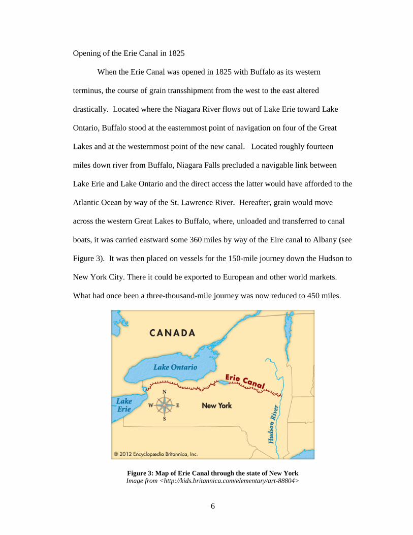
Opening of the Erie Canal in 1825
When the Erie Canal was opened in 1825 with Buffalo as its western
terminus, the course of grain transshipment from the west to the east altered
drastically. Located where the Niagara River flows out of Lake Erie toward Lake
Ontario, Buffalo stood at the easternmost point of navigation on four of the Great
Lakes and at the westernmost point of the new canal. Located roughly fourteen
miles down river from Buffalo, Niagara Falls precluded a navigable link between
Lake Erie and Lake Ontario and the direct access the latter would have afforded to the
Atlantic Ocean by way of the St. Lawrence River. Hereafter, grain would move
across the western Great Lakes to Buffalo, where, unloaded and transferred to canal
boats, it was carried eastward some 360 miles by way of the Eire canal to Albany (see
Figure 3). It was then placed on vessels for the 150-mile journey down the Hudson to
New York City. There it could be exported to European and other world markets.
What had once been a three-thousand-mile journey was now reduced to 450 miles.
Figure 3: Map of Erie Canal through the state of New York Image from <http://kids.britannica.com/elementary/art-88804>
7
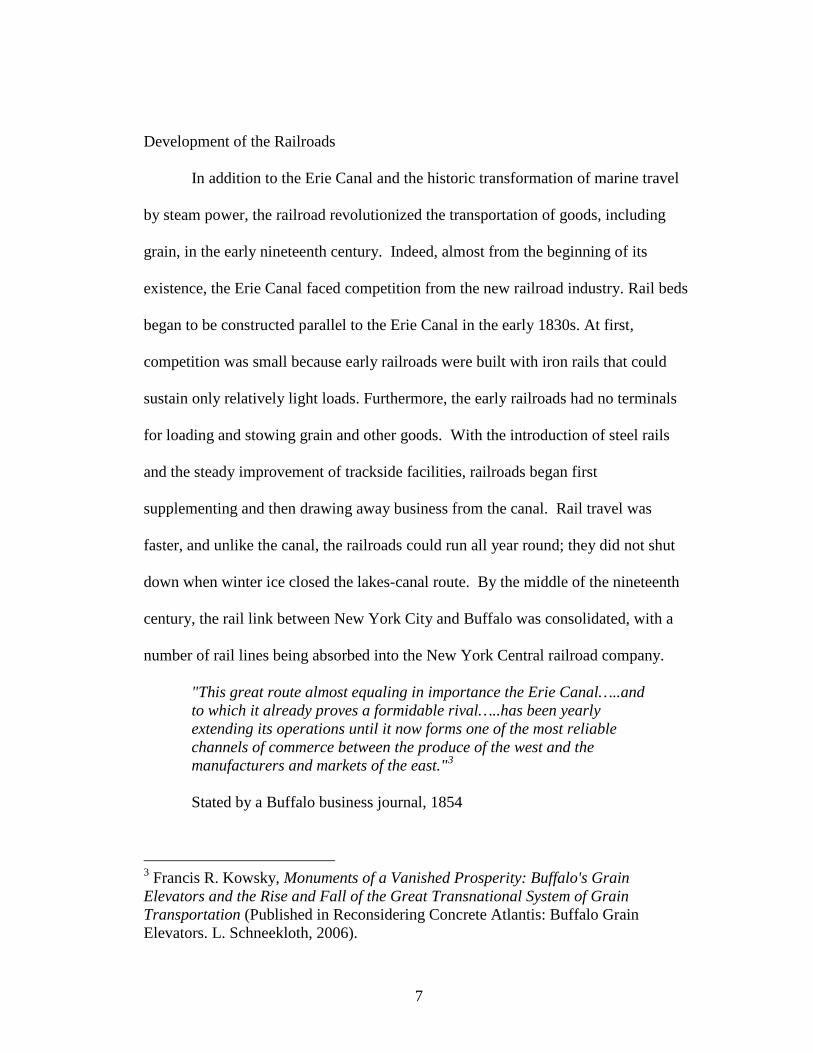
Development of the Railroads
In addition to the Erie Canal and the historic transformation of marine travel
by steam power, the railroad revolutionized the transportation of goods, including
grain, in the early nineteenth century. Indeed, almost from the beginning of its
existence, the Erie Canal faced competition from the new railroad industry. Rail beds
began to be constructed parallel to the Erie Canal in the early 1830s. At first,
competition was small because early railroads were built with iron rails that could
sustain only relatively light loads. Furthermore, the early railroads had no terminals
for loading and stowing grain and other goods. With the introduction of steel rails
and the steady improvement of trackside facilities, railroads began first
supplementing and then drawing away business from the canal. Rail travel was
faster, and unlike the canal, the railroads could run all year round; they did not shut
down when winter ice closed the lakes-canal route. By the middle of the nineteenth
century, the rail link between New York City and Buffalo was consolidated, with a
number of rail lines being absorbed into the New York Central railroad company.
"This great route almost equaling in importance the Erie Canal…..and to which it already proves a formidable rival…..has been yearly extending its operations until it now forms one of the most reliable channels of commerce between the produce of the west and the manufacturers and markets of the east."3 Stated by a Buffalo business journal, 1854
3 Francis R. Kowsky, Monuments of a Vanished Prosperity: Buffalo's Grain Elevators and the Rise and Fall of the Great Transnational System of Grain Transportation (Published in Reconsidering Concrete Atlantis: Buffalo Grain Elevators. L. Schneekloth, 2006).

8
By investing in steamboat lines along the Great Lakes as subsidiaries and by building
warehouse facilities and storage elevators at the terminus of the Buffalo River
waterfront, railroads eventually intensified their levels of commerce on grain
transportation within the Buffalo Niagara region.
Joseph Dart’s Elevator
As Buffalo's harbor became port of call to more and more vessels arriving to
unload grain, it was perhaps inevitable that invention would be applied to the
laborious process of transferring grain from lake vessels to canal boats. Handling the
grain by hand was slow and inefficient, causing delays and congestion of people and
boats in Buffalo Harbour. It was at this time that Buffalo entrepreneur Joseph Dart
and engineer Robert Dunbar who applied the new technology of the age to the
handling of grain. As the grain trade began to develop in Buffalo after the opening of
the Erie Canal, he turned his sights on this growing industry.
It seemed to me, as I reflected on the amazing extent of the grain producing regions of the Prairie West, and the favorable position of Buffalo for receiving their products, that the eastward movements of grain through this port would soon exceed anything the boldest imagination had conceived.
Joseph Dart
In 1842, Dart built the first steam-powered grain elevator. Dart, in addition
to creating the first steam transfer and storage elevator in the world, devised a
means of lowering the bottom end of the bucket into the holds of the large
vessels that brought grain across the Great Lakes or of the barges that moved
it along the Erie Canal. This was a turning point in the industry, marking a

9
shift from the manual labor of men on ladders to a mechanized system. One
of the most crucial features in Dart’s invention was the employment of a rigid,
nearly vertical frame to carry the bucket, chain, and sprocket assembly. This
vertical frame, if contained in a building of its own, was (and still is, where it
survives) identified as a "marine tower" or more familiarly as a "leg."4
Housed in a tall wooden sleeve, the conveyer could be canted outward at the
bottom of the elevator structure and lowered directly into the hold of a waiting
boat. Figure 4 illustrates how Joseph Dart’s elevator operated.
Figure 4: Flow Chart of Joseph Dart’s Grain Elevator Image from Buffalo and Erie County Historical Society
4 Reyner Banham, A Concrete Atlantis, pp. 110-111)

10
Figure 5: Historical Population chart of Buffalo, New York Image from Wikipedia
11
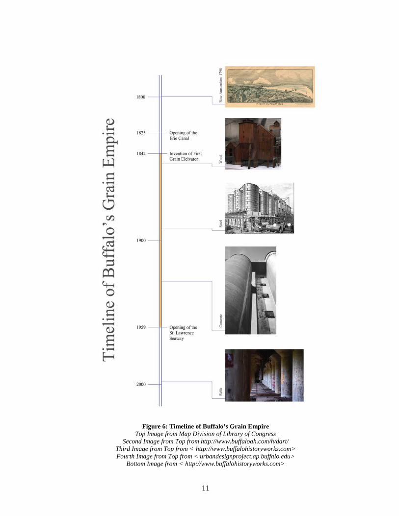
Figure 6: Timeline of Buffalo’s Grain Empire
Top Image from Map Division of Library of Congress Second Image from Top from http://www.buffaloah.com/h/dart/
Third Image from Top from < http://www.buffalohistoryworks.com> Fourth Image from Top from < urbandesignproject.ap.buffalo.edu>
Bottom Image from < http://www.buffalohistoryworks.com>

12
Figure 7: Graph of Buffalo’s Annual Grain Storage and Capacity Image from <www.conservapedia.com>
13
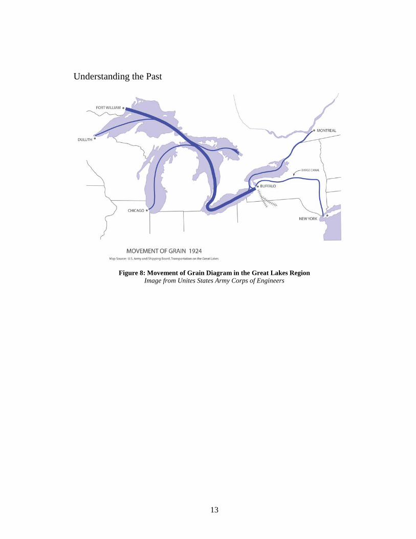
Understanding the Past
Figure 8: Movement of Grain Diagram in the Great Lakes Region Image from Unites States Army Corps of Engineers

14
Figure 9: Looking North on Buffalo River from Entrance to Clark & Skinner Canal near Michigan Avenue, 1899
Image from Detroit Publishing Company
Figure 10: Marine Leg lowered into Barge, Unloading at the Eastern Elevator, Buffalo, New York, 1899
Image from Detroit Publishing Company
15
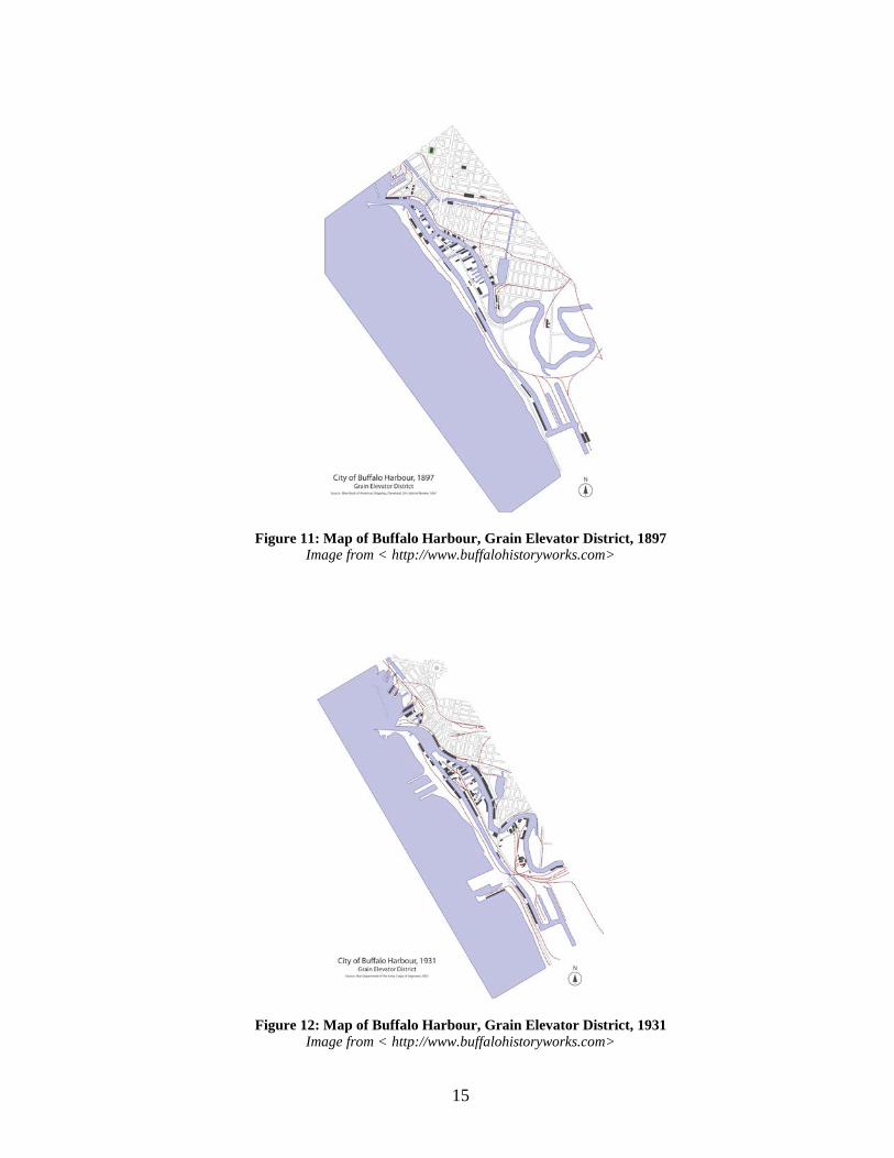
Figure 11: Map of Buffalo Harbour, Grain Elevator District, 1897 Image from < http://www.buffalohistoryworks.com>
Figure 12: Map of Buffalo Harbour, Grain Elevator District, 1931 Image from < http://www.buffalohistoryworks.com>
16
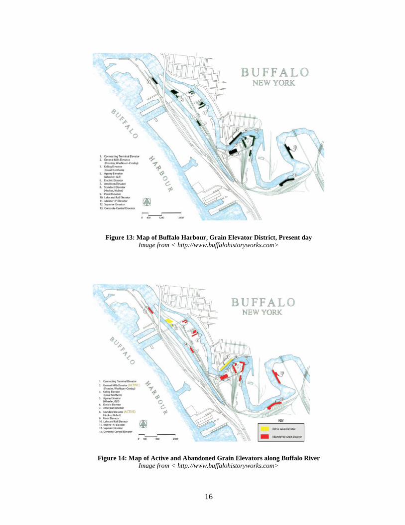
Figure 13: Map of Buffalo Harbour, Grain Elevator District, Present day Image from < http://www.buffalohistoryworks.com>
Figure 14: Map of Active and Abandoned Grain Elevators along Buffalo River Image from < http://www.buffalohistoryworks.com>

17
Area of Intervention and Analysis
Figure 15: Aerial Image of the City of Buffalo with Outlined Grain Elevator District Aerial Image from Google Earth
This thesis will focus on the grain elevators that are located along the banks of
the Buffalo River near the terminus into the lake Eerie waterbody (see Figure 15).
The Buffalo River divides the city of Buffalo into two distinct halves: the half to the
north with an established city grid relevant to the Joseph Ellicott plan, and the half to
the south heavily influenced by the grain and steel industry. The grain elevators built
along the Buffalo River are ideal docking areas for water vessels and barges because
18
these areas are shielded and protected from the lake winds that blow from the
southwest with excessive force. As the Buffalo River meanders its way through the
city of Buffalo, the historic grain elevators are heavily fortified in close proximity to
one another such that they are easily accessed by both barge and rail traffic. Grain
elevators typically respond to a site by being orientated parallel to the primary
direction of grain transportation and traffic. Many of the larger grain elevator
complexes that line the Buffalo River are orientated parallel to the riverbank because
transportation by water vessel was the primary method of grain transportation in
Buffalo.
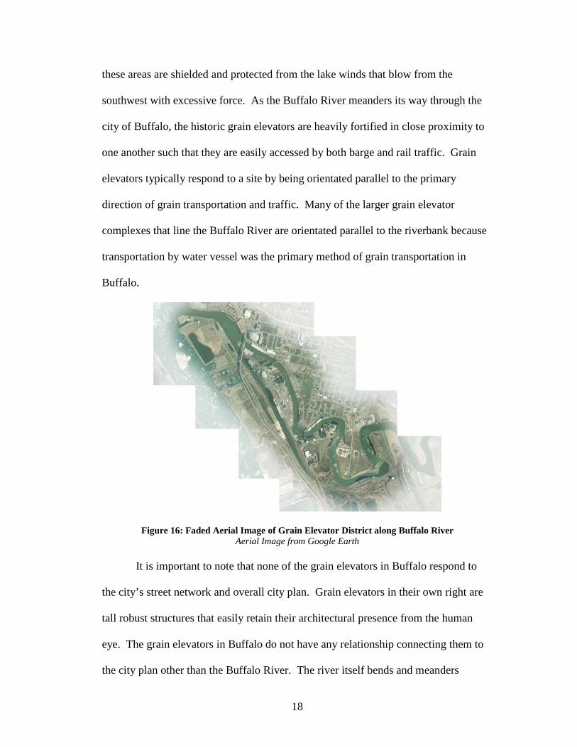
Figure 16: Faded Aerial Image of Grain Elevator District along Buffalo River Aerial Image from Google Earth
It is important to note that none of the grain elevators in Buffalo respond to
the city’s street network and overall city plan. Grain elevators in their own right are
tall robust structures that easily retain their architectural presence from the human
eye. The grain elevators in Buffalo do not have any relationship connecting them to
the city plan other than the Buffalo River. The river itself bends and meanders

19
around plots of land forming peninsulas, and the grain elevators follow the same
organic pattern (see Figure 16). To the naked eye, the grain elevators in Buffalo are
only perceived on the oblique by a distant measure because the Buffalo River
essentially isolates the grain elevator compounds from the adjacent neighborhoods
and communities (see Figure 17). In all their architectural presence, the grain
elevators in Buffalo are only appreciated from a distant view, deprived of any
interaction at close proximity, and left in isolation from the surrounding city.
Figure 17: Street Level View of First Ward Neighborhood with Standard Elevator in Background, Buffalo, New York
Image from <http//:www.global site plans.com> One might question: ‘Why are the grain elevator complexes in Buffalo
located in isolation from the rest of the city?’ Quite simply, a typical grain elevator
complex is not an ideal place for inhabitation and public interaction amongst
civilians. Grain elevators are strictly utilized for the storage and distribution of grain.
Furthermore, the terminal grain elevators in Buffalo require considerable adjacent
20
infrastructure in order to efficiently distribute grain. Freight trains, barges, and
tractor trailers are all simultaneously navigating around the confines of a grain
elevator complex, which makes the premises extraordinarily dangerous when in
operation. Railroad lines and freight yards were excessively developed and built in
conjunction with the grain elevators along the industrial parcels of land located to the
south of the Buffalo River, which made it almost impossible for the development of
traditional neighborhood planning to take place. It’s also important to understand the
typology of the grain elevator is prone to rare dust explosions that can be catastrophic
in magnitude. The grain elevators in Buffalo, with an exception to the Standard
Elevator, were all built at a safe distance away from nearby communities and adjacent
neighborhoods to prevent a disaster from spreading if a dust explosion were to occur.
21
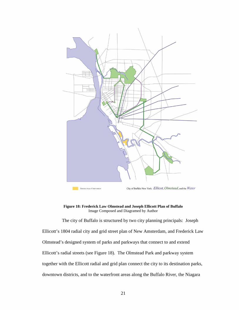
Figure 18: Frederick Law Olmstead and Joseph Ellicott Plan of Buffalo Image Composed and Diagramed by Author
The city of Buffalo is structured by two city planning principals: Joseph
Ellicott’s 1804 radial city and grid street plan of New Amsterdam, and Frederick Law
Olmstead’s designed system of parks and parkways that connect to and extend
Ellicott’s radial streets (see Figure 18). The Olmstead Park and parkway system
together with the Ellicott radial and grid plan connect the city to its destination parks,
downtown districts, and to the waterfront areas along the Buffalo River, the Niagara

22
River, and Lake Erie. It is interesting to note the Olmstead Park and parkway system
do not ultimately tie into the Grain Elevator district along the Buffalo River. With a
strong architectural presence, the grain elevators would seemingly benefit from a
green corridor that establishes a link from downtown Buffalo that stretches through
the Grain Elevator District and continues to extend into South Buffalo. This link
could add value to the grain elevators, and ultimately sponsor a preservation strategy
that would reduce the threat of demolition.
Figure 19: Grain Elevator District in Relationship to Downtown District Image Composed and Diagramed by Author with Aerial Background Content from Google Earth
In relationship to where it is located at the scale of the city, the Grain Elevator
district is situated between the Downtown District located to the north, and Tifft
Nature Preserve located to the south (see Figure 19). The Tifft Nature Preserve is a
23
264-acre urban nature preserve, which is dedicated to protection of the site’s natural
resources, scientific research, environmental education, and public enjoyment.
Located in South Buffalo, the Tifft Nature Preserve was an area formerly used as a
farm, stockyard, railroad shipping center, and dumping facility until the City of
Buffalo created the first urban nature sanctuary on a restored brownfield site in the
early 1970’s.5 The Grain Elevator District is within a one mile radius of both the
Tifft Nature Preserve and the Downtown District. The primary artery connecting the
Tifft Nature Preserve in South Buffalo to the Downtown District located to the north
is Ohio Street, which is a two lane roadway that runs in a north-south direction along
the Lake Erie shoreline.
The Buffalo River is a recovering riparian system. The river has a history of
heavy industrial discharge that resulted in poor water quality and badly contaminated
sediments. The Buffalo river was considered biologically dead as recently as the
early 1970’s, and it was designated as a Great Lakes area of concern in the 1980’s by
the New York State Department of Environmental Conservation. Combined sewer
overflows and upstream pollutant inputs remain concerns, but historical sediment
contamination and poor habitat opportunities persist as the major obstacles to
recovery. Pertaining to this thesis, how can habitat restoration along areas of the
Buffalo River be linked to grain elevator reuse?
5 Lauren Makeyenko, Energy Efficiency and Enhancements at Tifft Nature Preserve (Green Renaissance of Western New York, April, 2012).

24
Figure 20: Area of Environmental Concern, Buffalo River Image from < http://buffaloriverermp.ene.com/>
Figure 21: Satellite Image of Industrial Land Parcels, Buffalo, New York Image from < http://www.city-data.com/city/Buffalo-New-York.html>

25
Figure 22: Childs Street Industrial Complex, Existing Site Plan Image Composed and Diagramed by Author
The area of concern this thesis narrows down to and addresses within the
Grain Elevator District along the Buffalo River is the Childs Street Industrial District.
The Childs Street Industrial District is located off the Buffalo River, on a peninsula of
land directly south of the First Ward District. Present day, there are five existing
grain terminal elevators that make up the entire district: Electric Elevator, American
Elevator, Perot Elevator, Lake and Rail Elevator, and Marine A. Elevator. The
arrangement of the cluster of grain elevators on the site is rather disorganized with no
clear organizing principle. Three of the industrial buildings are oriented at an
orthogonal angle in relationship to Childs Street, while the remaining structures are
fronted to face the Buffalo River. This random gothic like aggregation of grain
elevators is what ultimately characterizes the Childs Street Industrial Complex as a
unique site, almost indicative of a reliquary of industrial ruins. Of the five remaining
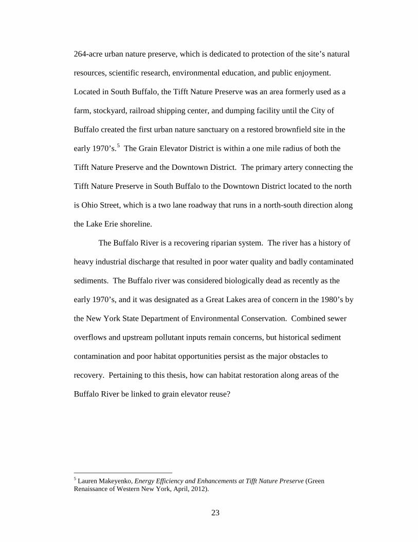
26
grain elevators, only the Lake and Rail Elevator complex is still in operational use
today, with only a fraction of its silo storage capacity being utilized to store grain (see
Figure 23).
Figure 23: Active vs. In-active Grain Elevators Image Composed and Diagramed by Author
Directly across the Buffalo River located to the north, stands the Standard
Elevator, which is still in operation today. Where the Buffalo River flows around the
grain elevators at the Childs Street Industrial District, this part of the river is famously
referred to as ‘Elevator Alley.’ The term ‘Elevator Alley’ refers to the close
proximity of grain elevators that dominate the edge conditions along the Buffalo
River with soaring heights above the ground plane (see Figure 28).
27
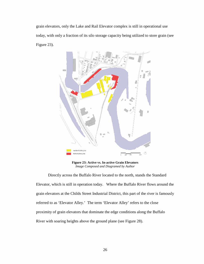
The Childs Street Industrial Complex is accessed by three methods of
transportation: roadway, barge, and rail line. The primary point of entry into the site
by means of roadway is the intersection Ohio Street and Childs Street (see Figure 24).
This point of entry into the site by roadway is the only access point for cars and
tractor trailers.
Figure 24: Site Access into Childs Street Industrial District Image Composed and Diagramed by Author
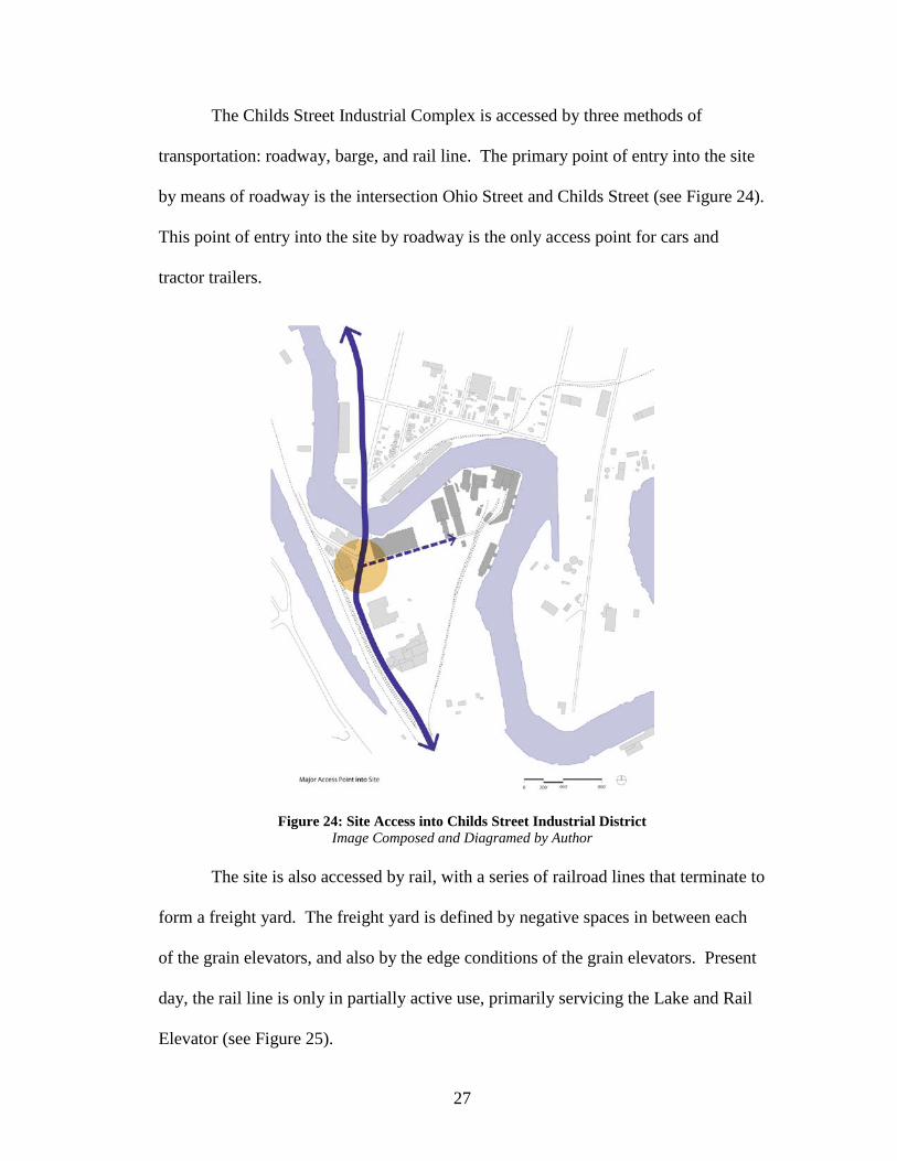
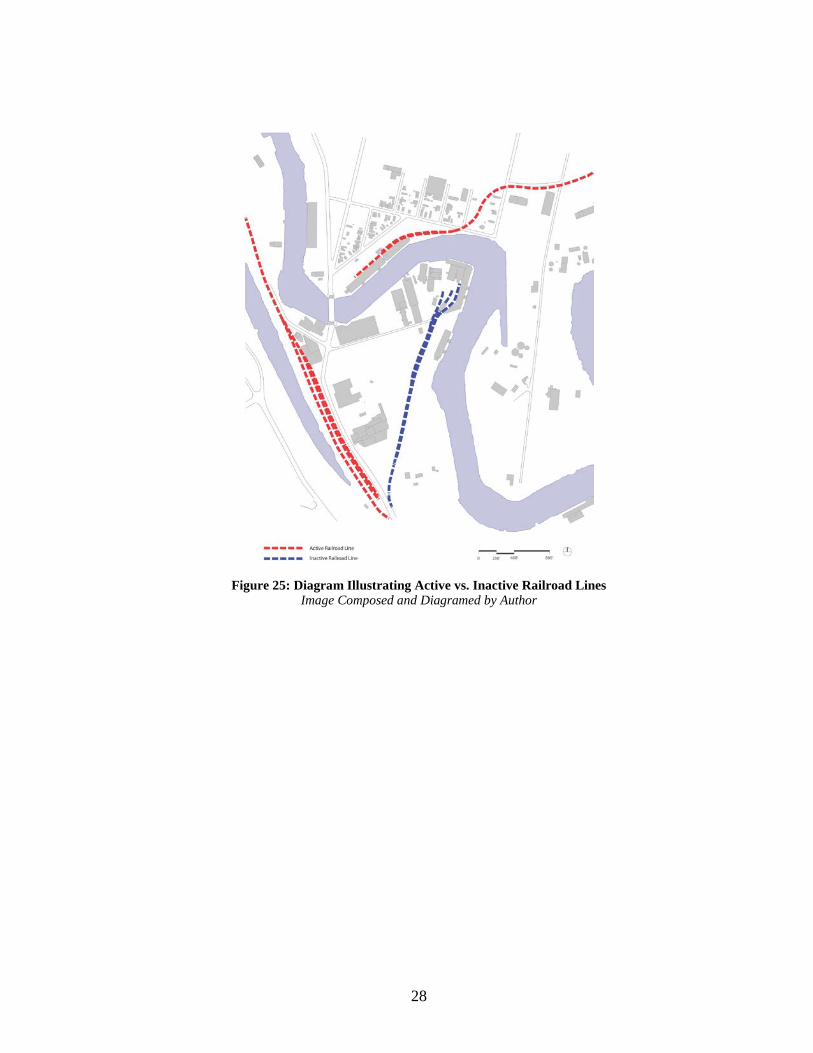
The site is also accessed by rail, with a series of railroad lines that terminate to
form a freight yard. The freight yard is defined by negative spaces in between each
of the grain elevators, and also by the edge conditions of the grain elevators. Present
day, the rail line is only in partially active use, primarily servicing the Lake and Rail
Elevator (see Figure 25).
28
Figure 25: Diagram Illustrating Active vs. Inactive Railroad Lines Image Composed and Diagramed by Author
29
Site Photographs
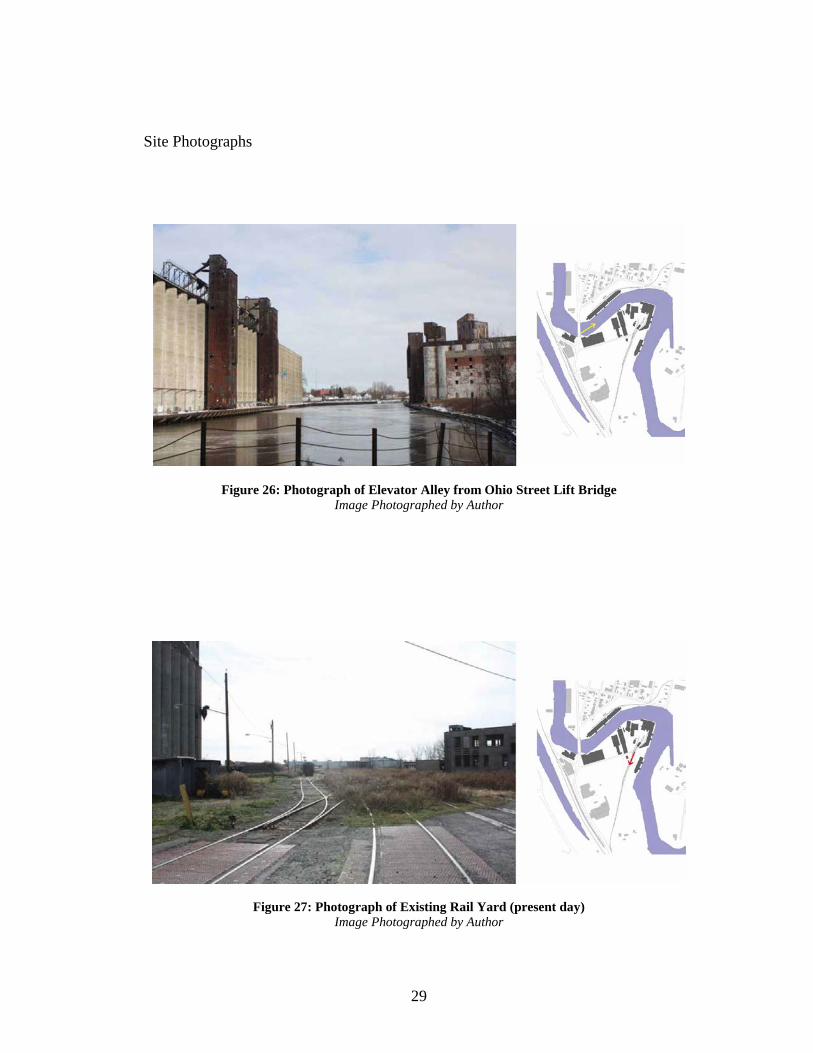
Figure 26: Photograph of Elevator Alley from Ohio Street Lift Bridge Image Photographed by Author
Figure 27: Photograph of Existing Rail Yard (present day) Image Photographed by Author

30
Figure 28: Photograph of Elevator Alley, looking Southwest Image Photographed by Author
Figure 29: Photograph of Existing Workhouse at American Elevator Image Photographed by Author
31
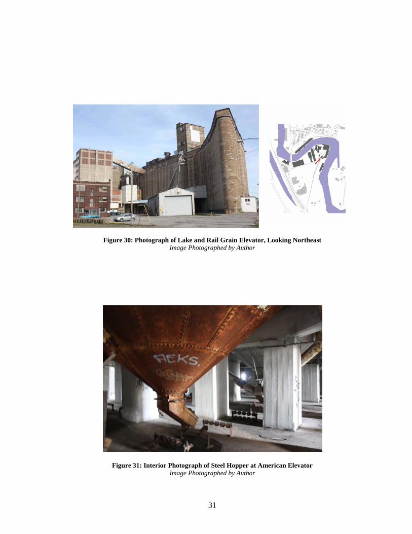
Figure 30: Photograph of Lake and Rail Grain Elevator, Looking Northeast Image Photographed by Author
Figure 31: Interior Photograph of Steel Hopper at American Elevator Image Photographed by Author
32
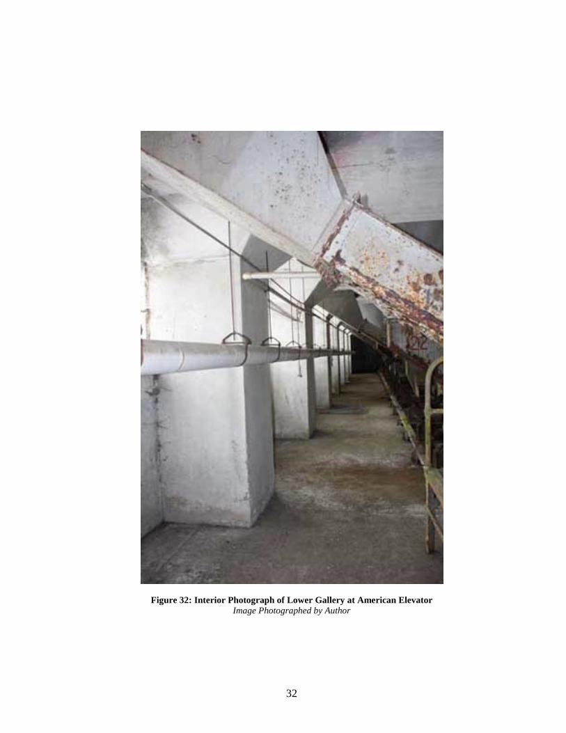
Figure 32: Interior Photograph of Lower Gallery at American Elevator Image Photographed by Author

33
Chapter 3: Defining the Problem Understanding Derelict Sites
In the context of today, cities are recognized as cultural entities that contain
depictions from the past, by way of the present, to the future, proceeding through the
entire cultural evolution of the “city as object.” Outlining the history of an existing
city, a city is influenced by the accumulation of different visions, different urban
models, and by significant changes in consumption and production patterns. Similar
or unlike, every city possesses its own tale to a growing empire, where its tale is
distinguished by sentiments of time.
The end of the twentieth century has created a break in the industrial sector
and with it an accelerating obsolescence of industrial landscapes.6 The industrialized
world is experiencing similar effects of the restructuring of the global economy, the
automation of production processes, and the relocation of industry to areas
characterized by low production costs.7 The global expansion of industry
consequently affects industrial regions all over the world, contributing to the
appearance of derelict and post-industrial landscapes that intensify the reduction of
development potential and the quality of life.8 In regards to the truth, industrial
landscapes are hindered economically, environmentally degraded, and socially
challenged through industrial contamination. Confronted with the challenges ahead,
6 Thomas Sieverts, Cities without Cities: An Interpretation of the Zwischenstadt. (London & New York: Spon Press, 2003). 7 Fredric Jameson, Postmodernism or, the Cultural Logic of Late Capitalism. (NC: Duke University Press, 1991). 8 J Handley, The Post Industrial Landscape. (The Groundwork Foundation: Birmingham, 1996).
34
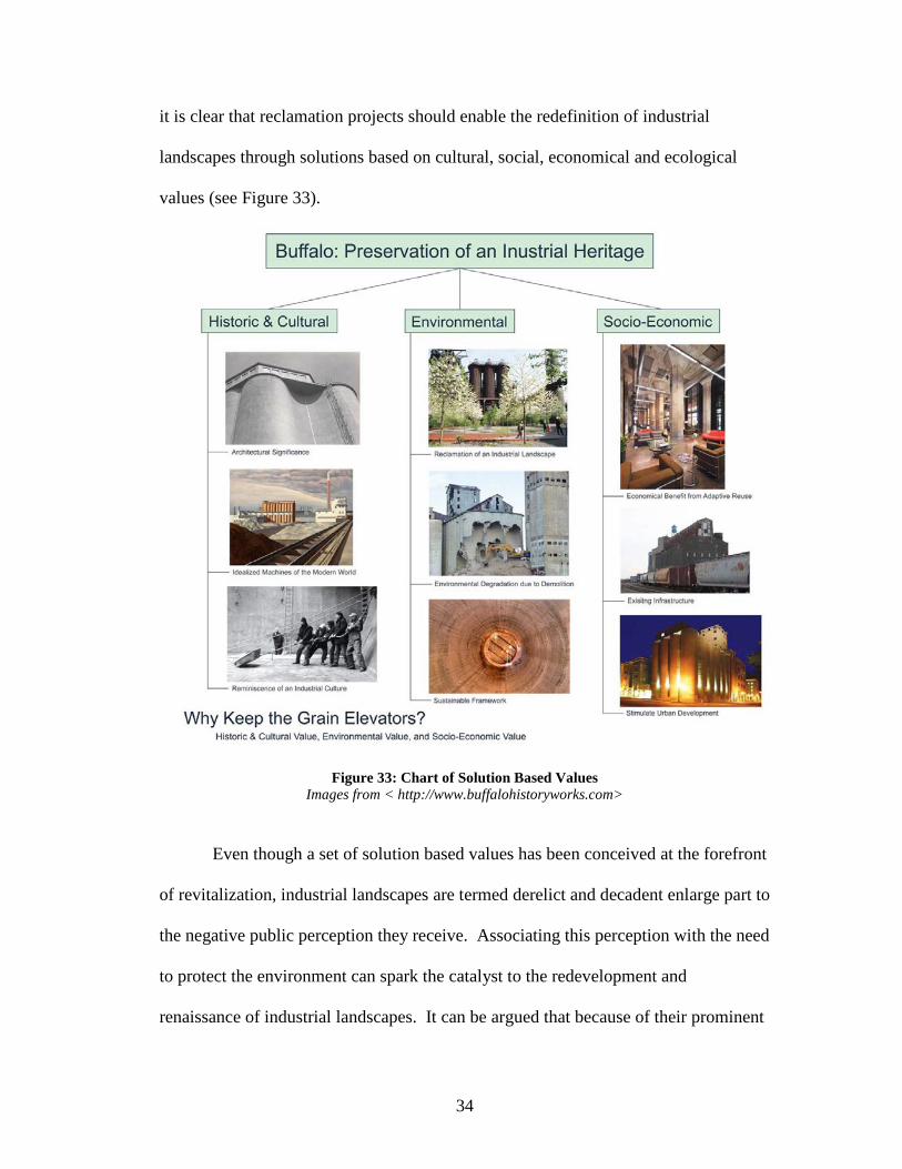
it is clear that reclamation projects should enable the redefinition of industrial
landscapes through solutions based on cultural, social, economical and ecological
values (see Figure 33).
Figure 33: Chart of Solution Based Values Images from < http://www.buffalohistoryworks.com>
Even though a set of solution based values has been conceived at the forefront
of revitalization, industrial landscapes are termed derelict and decadent enlarge part to
the negative public perception they receive. Associating this perception with the need
to protect the environment can spark the catalyst to the redevelopment and
renaissance of industrial landscapes. It can be argued that because of their prominent

35
locations near downtown districts, embanked along waterways, supported by existing
infrastructure, and neighboring to residential communities, industrial landscapes
embody enormous potential to be functionally productive and reintegrated into the
surrounding community.
Buffalo’s Industrial Landscape
As industrialization expanded in the city of Buffalo, it promoted significant
changes in the landscape: higher densities in urban areas and the urbanization of the
natural and rural environment. The city of Buffalo thus acquired a new industrial
face, a face that was shaped both physically and culturally by industrialization.
Buffalo’s industrial face cultivated a landscape defined by the aggregation of
industrial complexes and by the needs of a growing population. Over the past few
decades, with the city of Buffalo victimized of the declining grain trade,
deindustrialization, industrial relocation, and economic reconversion has had a
profound impact on industrial sites all over the Buffalo-Niagara region and thus
facilitated a vast array of obsolete industrial facilities. Together with its forgotten
role as a functioning industrial empire and a plethora of abandoned and dilapidated
industrial structures now characterizing the industrial landscape in Buffalo, the city’s
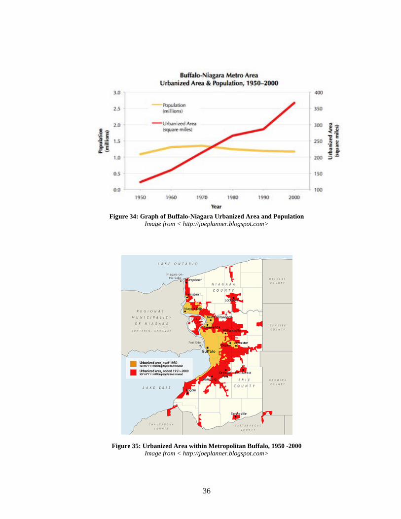
population has steadily declined and expanded outwards in recent decades (see
Figures 34 & 35).
36
Figure 34: Graph of Buffalo-Niagara Urbanized Area and Population
Image from < http://joeplanner.blogspot.com>
Figure 35: Urbanized Area within Metropolitan Buffalo, 1950 -2000 Image from < http://joeplanner.blogspot.com>

37
Why should Buffalo’s Cultural (Industrial) Landscape be Reclaimed and Protected?
Cultural landscapes give us a “sense of place and reveal our relationship with
the land over time.”9 They are places that characterize our “origin and development
through their forms, features, and history of use.”10 Along the Buffalo River, it is
important to recognize the entire industrial landscape as a single entity, as opposed to
recognizing a building, or a group of buildings of an industrial site, because it will
enhance the conception of industrial preservation to accommodate “recognized
patterns of activity in time and place.”11 With the intention to ascribe it a new
meaning by adapting to new program standards and new cultural uses, the concept of
industrial landscape is used to describe and identify the remnant materials of the
industrial culture.
Historic and Cultural Values
The justification to protect and reclaim the grain elevators of Buffalo will be
based on diverse criteria, which considers their environmental, economical, and
cultural value. Grain elevators, similar to their colossal size and ability to store grain,
possess an enormous amount of cultural heritage in Buffalo simply because of their
dominating presence as architectural icons. Synthesizing cultural values of grain
elevators with economic opportunities on industrial landscapes can formulate the
9 Paul Drury, The Historic and Cultural Dimensions of Landscape. Naturopa, No.98 (Belgium: Bietlot Gilly, 2002) pp.12-13. 10 Marc Antrop, Why Landscapes of the Past are Important for the Future. Landscape and Urban Planning, vol. 70 (Belgium: Ghent University, 2000). 11 Donald Meinig, The Interpretation of Ordinary Landscapes: Geographical Essays. (Oxford: Oxford University Press, 1979).
38
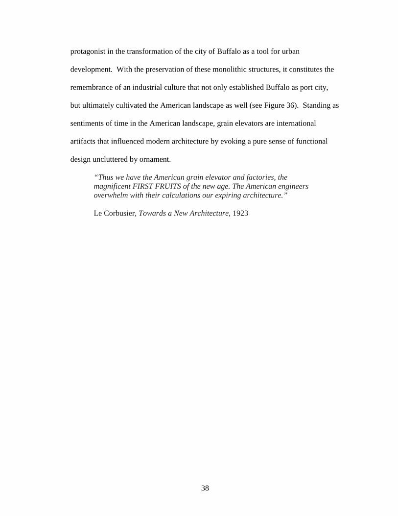
protagonist in the transformation of the city of Buffalo as a tool for urban
development. With the preservation of these monolithic structures, it constitutes the
remembrance of an industrial culture that not only established Buffalo as port city,
but ultimately cultivated the American landscape as well (see Figure 36). Standing as
sentiments of time in the American landscape, grain elevators are international
artifacts that influenced modern architecture by evoking a pure sense of functional
design uncluttered by ornament.
“Thus we have the American grain elevator and factories, the magnificent FIRST FRUITS of the new age. The American engineers overwhelm with their calculations our expiring architecture.” Le Corbusier, Towards a New Architecture, 1923

39
Figure 36: Classic Landscape, Oil Painting by Charles Sheeler, 1931 Image from <www.artchive.com>
Environmental Values
Aside from being physically intimidating at the scale of the human eye, grain
elevators evoke environmental concerns that are completely devoid when compared
to conventional industrial facilities. The typical industrial factory of the twentieth
century is perceived as an entity that contaminates, pollutes, and quarantines itself
from the surrounding community. Grain elevators, on the other hand, present no
immediate environmental concern other than the sheer size they occupy at the scale of
the city. If a grain elevator is to be dormant and distant from its original purpose as a
terminal elevator, then the only threat it poses against the environment is the threat

40
against demolition. Demolition, in its nature, revolves around the notion of the
deconstruction of building material that ultimately produces environmental side
effects.
Would it be environmentally beneficial to demolish a grain elevator? One
must first be mindful of the material culture that a grain elevator, the grain elevators
of Buffalo in particular, naturally inherits. With the exception of one, the standing
grain elevators in Buffalo are all conceived of concrete as the primary material
component. By nature, concrete is energy inefficient during its formulation process,
but extremely efficient in its structural integrity and sustainable lifespan as an aging
material. Having been constructed within the most recent century, the grain elevators
in Buffalo may have outlived their original purpose, but have not outlived their
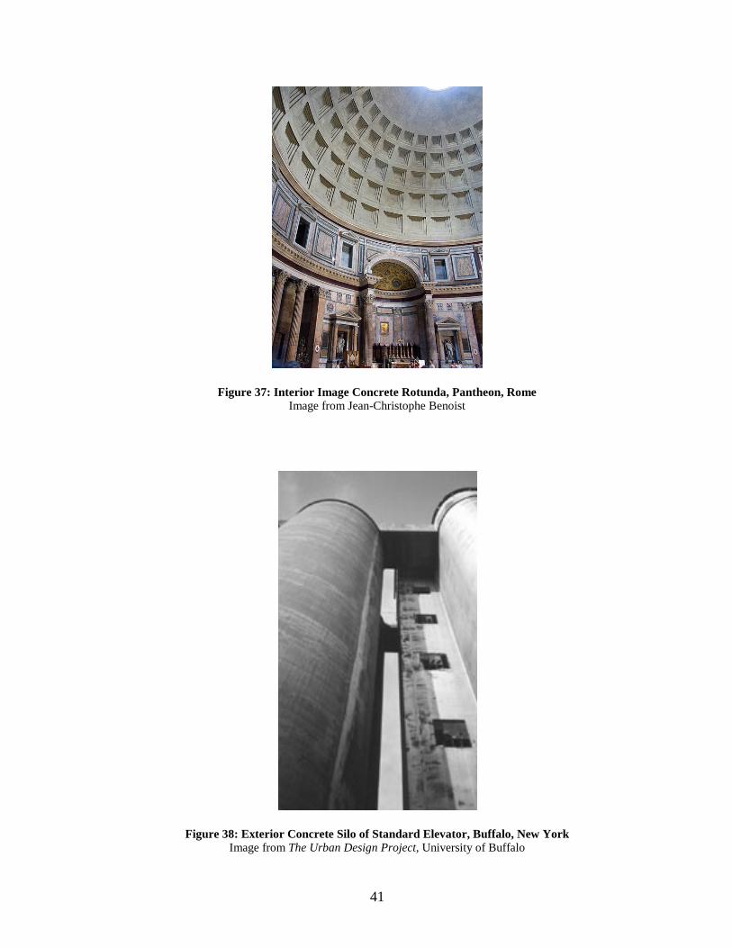
structural integrity. Argued by many, the most sustainable structure to have ever
been built is the Pantheon in Rome. Having survived for over two thousand years,
the Pantheon owes is its aging lifespan in large part to its durable and resilient
material use of concrete (see Figure 37). To the extent at which concrete sustains the
structural integrity of the grain elevators in Buffalo, to demolish them would be
foolish and a missed opportunity would result, and their potential use as sustainable
monolithic structures would be undervalued.
41
Figure 37: Interior Image Concrete Rotunda, Pantheon, Rome Image from Jean-Christophe Benoist
Figure 38: Exterior Concrete Silo of Standard Elevator, Buffalo, New York Image from The Urban Design Project, University of Buffalo

42
Social and Economic Values
The grain elevators of Buffalo not only represent a historic industrial past that
shaped the city both culturally and physically, but they also represent infrastructure
the city has invested in. Prior to the decline of the grain trade, the grain elevators as a
collective whole represented the economic wealth within the Buffalo Niagara region.
In the context of today, all the capitol utilized to build and construct the grain
elevators in Buffalo now ceases to exist with the absence of the grain trade. The
financial burden Buffalo now faces is whether or not to invest in a demolition strategy
that will tear down the grain elevator complexes over a period of time, or will the city
reinvest in the existing industrial infrastructure by repurposing the grain elevators.
Figuratively speaking, the cost to build and construct one single grain elevator
complex out of reinforced concrete and structural steel is considerably expensive.
The amount of energy utilized to provide the formwork and pouring of cement for a
network of concrete silos might be equal to the estimated cost and energy required to
demolish the same network of silos. If a new use can be conceived of that repurposes
both the existing grain elevators and surrounding infrastructure, the new proposed use
will raise the social and economic value of the grain elevator typology as a whole,
and reduce the threat of demolition.
From an economic standpoint, the cost of preservation compared to the cost of
demolition, are two opposing approaches that ultimately decide the future and fate of
an abandoned grain elevator complex. Is there any economic value to a dysfunctional
derelict grain elevator that has lost all reason for being, or will demolition of the

43
building and surrounding structures make better use of the land for future
development? Needless to say, the answer to that question can be studied on a case
by case basis because all grain elevators are inherently different from one to another.
In the case of Silo Point, an adaptive reuse project of a historic grain elevator
complex repurposed and converted to luxury condominiums in Baltimore, Maryland,
both social and economic values were reinvested into an abandoned industrial grain
terminal to bring about a new use. The original grain elevator complex was divided
into two different massing components: the workhouse, and silo bins (see Figure 39).
Although the workhouse was utilized for vertical distribution of grain, it also
contained a network of octagonal shaped storage bins built within its structural frame.
Figure 39: Massing Diagram Sketch of Silo Point, Baltimore, Maryland Image Drawn by Author
44
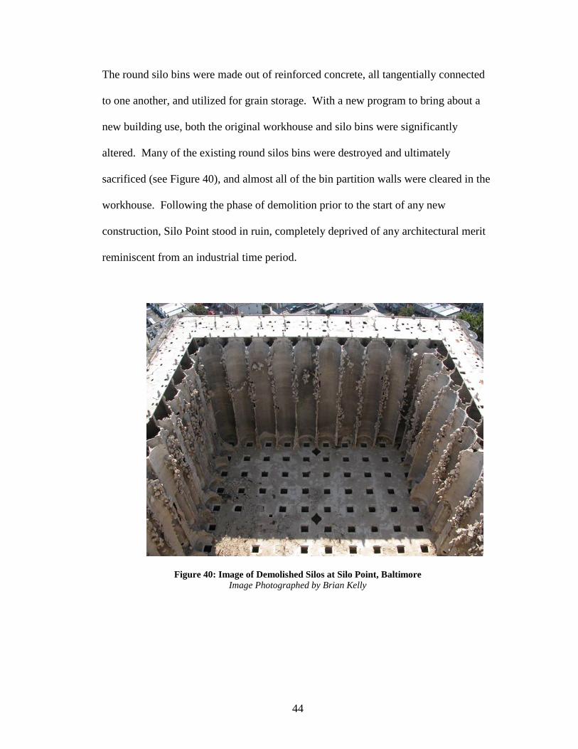
The round silo bins were made out of reinforced concrete, all tangentially connected
to one another, and utilized for grain storage. With a new program to bring about a
new building use, both the original workhouse and silo bins were significantly
altered. Many of the existing round silos bins were destroyed and ultimately
sacrificed (see Figure 40), and almost all of the bin partition walls were cleared in the
workhouse. Following the phase of demolition prior to the start of any new
construction, Silo Point stood in ruin, completely deprived of any architectural merit
reminiscent from an industrial time period.
Figure 40: Image of Demolished Silos at Silo Point, Baltimore Image Photographed by Brian Kelly
45
Chapter 4: Case Studies
Before an intervention occurs on a site of previous development, analysis and
research must be completed in order to develop new strategies and ideas that
formulate a rational proposal. When trying to intervene on the Childs Street
Industrial Complex in Buffalo, an appropriate narrative must be conceived of by
investigating relevant past precedents that confront comparable points of issue. There
are three case study approach themes that address projects with different design
typologies, but also with different design program. Design strategies for the
reclamation of the Childs Street industrial Complex in Buffalo will focus on these
different themes: Socio-Economic, Historic and Cultural, and Environmental and
Aesthetic.
Historic and Cultural The Distillery District, Toronto, Canada, 2001
The Distillery District is a thirteen acre de-industrialized historical site that
has been redeveloped and reused to form an entertainment precinct located in
Toronto, Canada. The closing of the remaining distillery operation in 1990 created
redevelopment and investment opportunities for a district that contained the largest
and most well preserved collection of Victorian-era industrial architecture in North
America. As an industrial centre for transshipment in North America in the twentieth
century, the city of Toronto was confronted with the problem of de-industrialization.
The winding down of distillery operations left derelict buildings unused and subject

46
to demolishing. With a unique collection of Victorian-era industrial architecture, the
Distillery District created redevelopment and investment opportunities based on
combining de-industrialization and cultural globalization.
Figure 41: Aerial Image of Distillery District, Toronto Canada Aerial Image by Google Earth
Figure 42: Aerial View of Distillery District, Toronto Canada Image from Michelle Lu0Do, 2008

47
Figure 43: Street Level View of Distillery District, Toronto Canada Image from Art Branch, 2011
Environmental and Aesthetic Emscher Park, Germany In Emscher Park, Germany, the adaptation of an industrial landscape into a
network of reclaimed parks has been used to drive the restoration of one of the most
degraded landscapes in Europe. Emscher Park is located in the Ruhr Valley in
Western Germany, and was the country’s industrial heartland for more than a century.
With the decline in Germany’s industrialization in the 1920’s, mines and factories in
the region began to close and fall silent, and their gates closed as they became
brownfield sites in need of restoration. The transformation of a once industrial
heartland into a reclaimed landscape suggests how powerful the concept of a park can
be once the boundaries of the traditional definition are challenged.
48
Given the terminology of an ‘imaginative landscape out of industrial
dereliction,’ Emscher Park has been created by multiple practitioners including
architects, artists, gardeners, scientists and planners.12 Out of the abandoned coke
plants, blast furnaces, ore bunkers, and manganese depots, a deprived industrial
landscape has been transformed into a heterogeneous landscape to spawn new
purpose and activity. By allowing the reclamation of ruined spaces by plants and
animals to simply inhabit in certain areas, by removing patches of industrial
contamination, and through the deliberate fabrication of ponds, meadows, and
gardens, a hybrid mixture landscape of places both untouched and transformed has
been created.
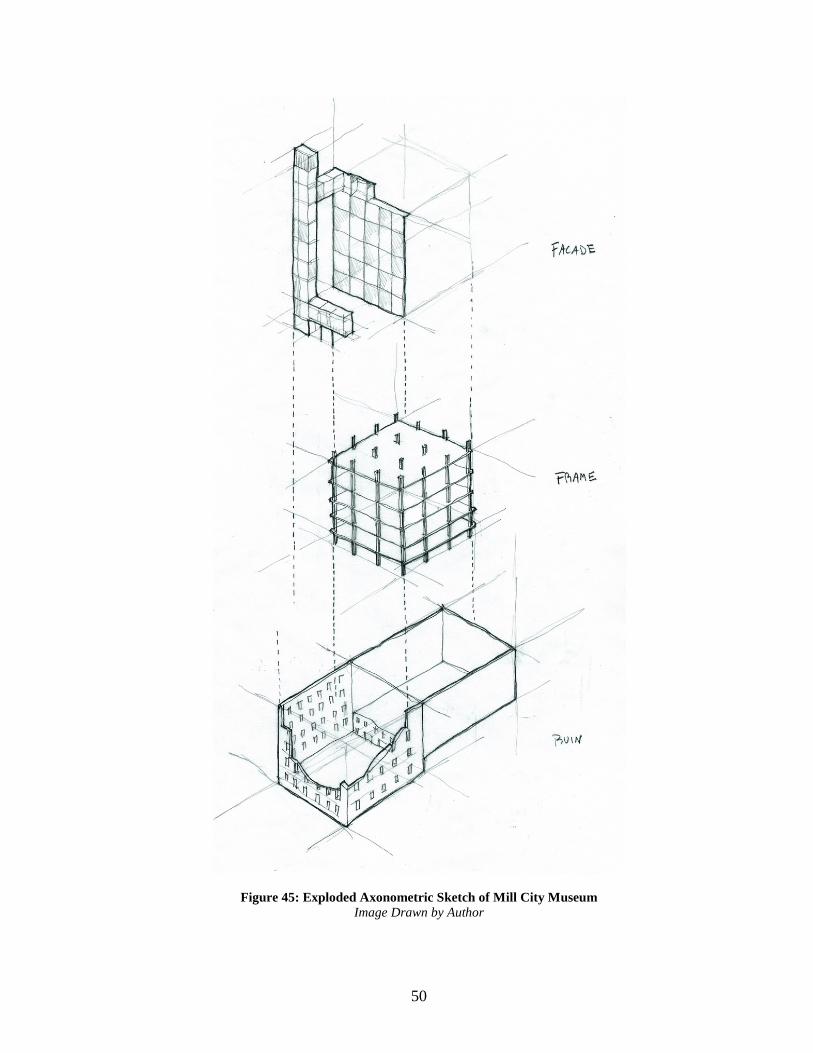
Social and Economic Mill City Museum, Minneapolis Mill City Museum is an example of adaptive reuse of an industrial ruin based
on the theme of socio-economic. The case study of the Mill City Museum selectively
investigates the social and economic influence a single repurposed industrial ruin can
have on a surrounding neighborhood and city. Originally a flour mill dating to 1880,
the structure housing the present day Mill City Museum was known as the Washburn
A. Mill, when it was nearly destroyed by fire in 1991. Milling operations were
abandoned in 1965, and after a fire in 1991, the mill stood in ruin, fragile, and
needing to be braced. The question for repurposing the building was how to turn the
12 Latz and Latz, 2001:73

49
ruin into something that could be used by the public, and yet would honor the history
of the Minneapolis Milling industry.
Figure 44: Aerial Image of Mill City Museum, Minneapolis, Minnesota Aerial Image by Google Earth
50
Figure 45: Exploded Axonometric Sketch of Mill City Museum Image Drawn by Author

51
Chapter 5: Design Proposal Infusion of New Industry The big underlying question of this thesis is: What is the physical
intervention that will take place inside the core of an empty grain silo? To answer
that question will be the infusion of new industry, but more specifically, what is the
“new industry” to be inserted in the emptiness of concrete silos? The new industry is
the same known technology that is used to generate the biological process of
anaerobic digestion for wastewater treatment, and infusing it inside the core of an
existing concrete silo. Anaerobic digestion is a biological process by which
microorganisms break down biodegradable material in the absence of oxygen. In
other words, anaerobic digestion is the same natural process that humans and all
living organisms utilize to digest food and dispose organic waste.
One might question, why does it make sense to retrofit an abandoned grain
silo to support the process of anaerobic digestion? To understand and answer that
question would be to link the inherent properties of a typical anaerobic digester to that
of an empty concrete silo. The ideal properties of an anaerobic digester are dark
spaces containing no oxygen, while round and resembling the shape of a cylinder in
architectural form. To perform at a high rate of efficiency, an anaerobic digester is
extremely well insulated to prevent heat loss and maintain an internal temperature,
and built at a minimum height to diameter ratio of three to one. Similarly, a concrete
grain silo is round and cylindrical in architectural form, where grain is initially stored
in dark spaces containing little to no oxygen to prevent vermin contamination and
dust explosions.
52
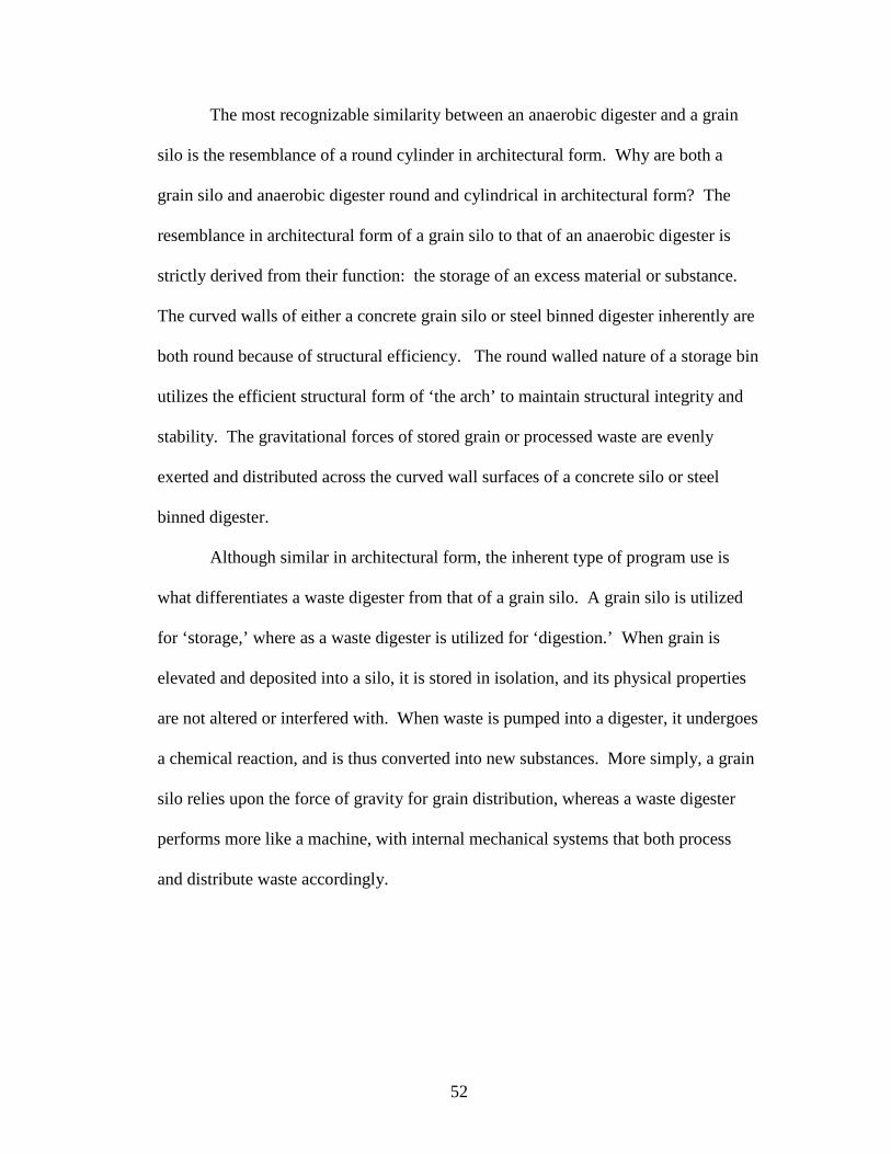
The most recognizable similarity between an anaerobic digester and a grain
silo is the resemblance of a round cylinder in architectural form. Why are both a
grain silo and anaerobic digester round and cylindrical in architectural form? The
resemblance in architectural form of a grain silo to that of an anaerobic digester is
strictly derived from their function: the storage of an excess material or substance.
The curved walls of either a concrete grain silo or steel binned digester inherently are
both round because of structural efficiency. The round walled nature of a storage bin
utilizes the efficient structural form of ‘the arch’ to maintain structural integrity and
stability. The gravitational forces of stored grain or processed waste are evenly
exerted and distributed across the curved wall surfaces of a concrete silo or steel
binned digester.
Although similar in architectural form, the inherent type of program use is
what differentiates a waste digester from that of a grain silo. A grain silo is utilized
for ‘storage,’ where as a waste digester is utilized for ‘digestion.’ When grain is
elevated and deposited into a silo, it is stored in isolation, and its physical properties
are not altered or interfered with. When waste is pumped into a digester, it undergoes
a chemical reaction, and is thus converted into new substances. More simply, a grain
silo relies upon the force of gravity for grain distribution, whereas a waste digester
performs more like a machine, with internal mechanical systems that both process
and distribute waste accordingly.

53
New Industry: Anaerobic Digestion
Anaerobic Digestion is a biological process in which bacteria break down
biodegradable material in a controlled environment in the absence of oxygen.13 It
occurs naturally in anaerobic niches such as marshes, sediments, wetlands, and the
digestive tracts of ruminants and certain species of insects. Anaerobic digestion
systems are employed in many wastewater treatment facilities for sludge degradation
and stabilization, and are used in engineered anaerobic digesters to treat high-strength
industrial and food processing wastewaters prior to discharge. Internationally,
anaerobic digestion has been used for decades, primarily in rural areas, for the
production of biogas for use as a cooking and lighting fuel. Anaerobic digestion of
municipal solid waste is used in different regions worldwide to:
• Reduce the amount of material being land filled.
• Stabilize organic material before disposal in order to reduce future environmental impacts from air and water emissions. • Recover energy
Figure 41: Basic Process of Anaerobic Digestion Image from <www.hacaustralia.com>
13 California Integrated Waste Management Board, Current Anaerobic Digestion Technologies Used for Treatment of Municipal Organic Solid Waste (March 2008), pp. 1-2.
54
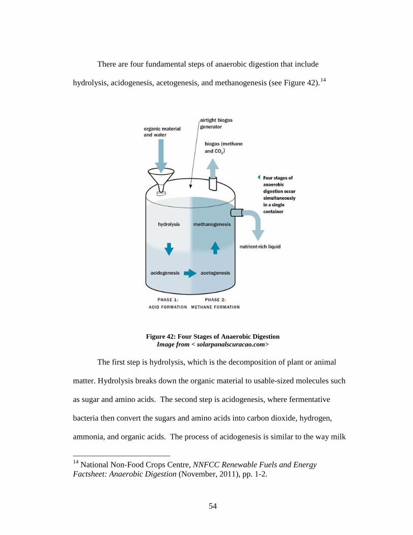
There are four fundamental steps of anaerobic digestion that include
hydrolysis, acidogenesis, acetogenesis, and methanogenesis (see Figure 42).14
Figure 42: Four Stages of Anaerobic Digestion Image from < solarpanalscuracao.com>
The first step is hydrolysis, which is the decomposition of plant or animal
matter. Hydrolysis breaks down the organic material to usable-sized molecules such
as sugar and amino acids. The second step is acidogenesis, where fermentative
bacteria then convert the sugars and amino acids into carbon dioxide, hydrogen,
ammonia, and organic acids. The process of acidogenesis is similar to the way milk
14 National Non-Food Crops Centre, NNFCC Renewable Fuels and Energy Factsheet: Anaerobic Digestion (November, 2011), pp. 1-2.
55
sours. The third step is acetogenesis, where acetogenic bacteria then convert these
resulting organic acids into acetic acid, along with additional ammonia, hydrogen,
and carbon dioxide. The final step is methanogenesis, which converts these products
to methane and carbon dioxide. Throughout the entire digestion process, large
organic polymers that make up biomass are broken down into smaller molecules by
chemicals and microorganisms. Upon completion of the anaerobic digestion process,
the biomass is converted into biogas, namely carbon dioxide and methane, as well as
digestate and wastewater.
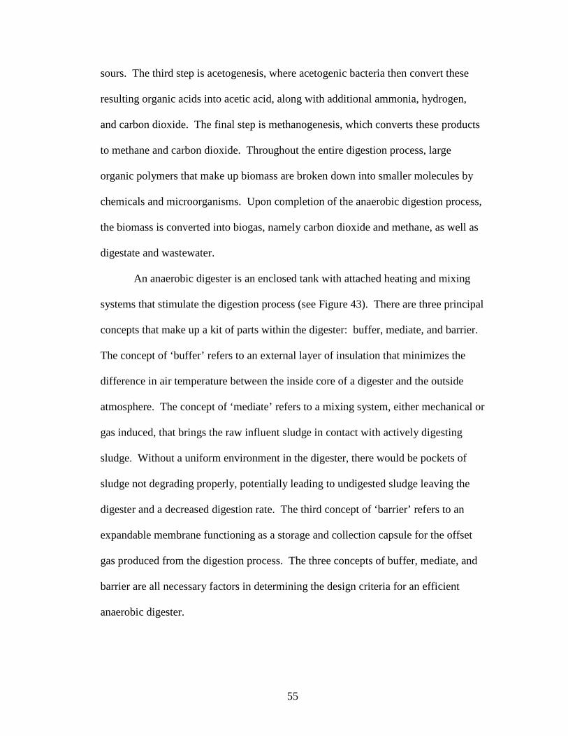
An anaerobic digester is an enclosed tank with attached heating and mixing
systems that stimulate the digestion process (see Figure 43). There are three principal
concepts that make up a kit of parts within the digester: buffer, mediate, and barrier.
The concept of ‘buffer’ refers to an external layer of insulation that minimizes the
difference in air temperature between the inside core of a digester and the outside
atmosphere. The concept of ‘mediate’ refers to a mixing system, either mechanical or
gas induced, that brings the raw influent sludge in contact with actively digesting
sludge. Without a uniform environment in the digester, there would be pockets of
sludge not degrading properly, potentially leading to undigested sludge leaving the
digester and a decreased digestion rate. The third concept of ‘barrier’ refers to an
expandable membrane functioning as a storage and collection capsule for the offset
gas produced from the digestion process. The three concepts of buffer, mediate, and
barrier are all necessary factors in determining the design criteria for an efficient
anaerobic digester.
56
Figure 43: Cross Section of an Anaerobic Digester Image from <http://www.mannvit.com>
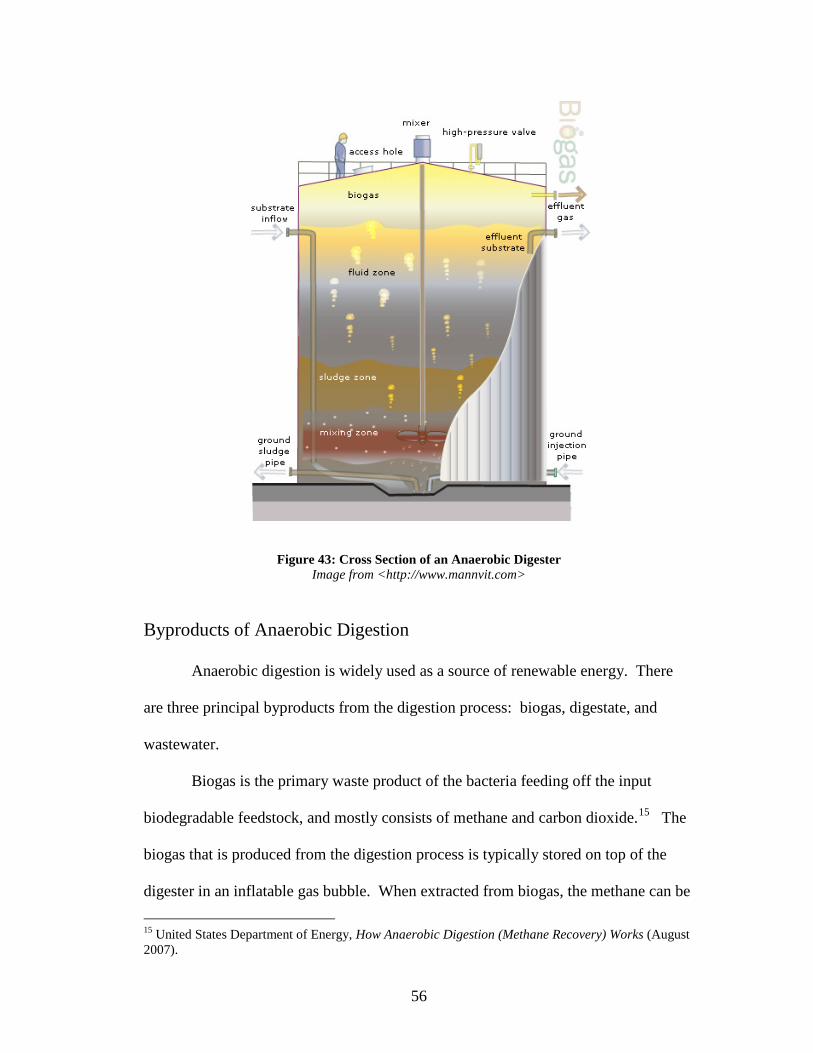
Byproducts of Anaerobic Digestion
Anaerobic digestion is widely used as a source of renewable energy. There
are three principal byproducts from the digestion process: biogas, digestate, and
wastewater.
Biogas is the primary waste product of the bacteria feeding off the input
biodegradable feedstock, and mostly consists of methane and carbon dioxide.15 The
biogas that is produced from the digestion process is typically stored on top of the
digester in an inflatable gas bubble. When extracted from biogas, the methane can be
15 United States Department of Energy, How Anaerobic Digestion (Methane Recovery) Works (August 2007).
57
burned to produce both heat and electricity. Electricity produced by an anaerobic
digester is considered to be renewable energy and may attract subsidies. Methane and
electrical power produced from anaerobic digestion facilities can be used to reduce
the dependence on energy derived from fossil fuels, which in part will reduce
emissions of greenhouse gases. In contrary to the carbon dioxide produced from the
combustion of fossil fuels, the biogas produced from anaerobic digestion does not
contribute to increasing atmospheric carbon dioxide concentrations. The reason is
because the biogas produced from anaerobic digestion is not directly released into the
atmosphere, and the carbon dioxide is generated from an organic source with a short
carbon cycle.
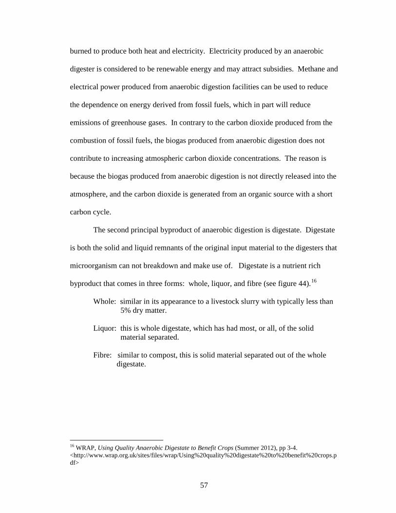
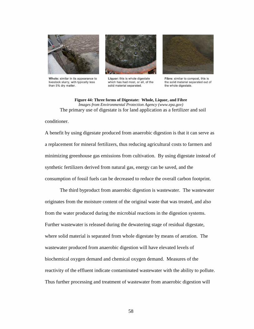
The second principal byproduct of anaerobic digestion is digestate. Digestate
is both the solid and liquid remnants of the original input material to the digesters that
microorganism can not breakdown and make use of. Digestate is a nutrient rich
byproduct that comes in three forms: whole, liquor, and fibre (see figure 44).16
Whole: similar in its appearance to a livestock slurry with typically less than 5% dry matter. Liquor: this is whole digestate, which has had most, or all, of the solid material separated. Fibre: similar to compost, this is solid material separated out of the whole digestate.
16 WRAP, Using Quality Anaerobic Digestate to Benefit Crops (Summer 2012), pp 3-4. <http://www.wrap.org.uk/sites/files/wrap/Using%20quality%20digestate%20to%20benefit%20crops.pdf>
58
Figure 44: Three forms of Digestate: Whole, Liquor, and Fibre Images from Environmental Protection Agency (www.epa.gov)
The primary use of digestate is for land application as a fertilizer and soil
conditioner.
A benefit by using digestate produced from anaerobic digestion is that it can serve as
a replacement for mineral fertilizers, thus reducing agricultural costs to farmers and
minimizing greenhouse gas emissions from cultivation. By using digestate instead of
synthetic fertilizers derived from natural gas, energy can be saved, and the
consumption of fossil fuels can be decreased to reduce the overall carbon footprint.
The third byproduct from anaerobic digestion is wastewater. The wastewater
originates from the moisture content of the original waste that was treated, and also
from the water produced during the microbial reactions in the digestion systems.
Further wastewater is released during the dewatering stage of residual digestate,
where solid material is separated from whole digestate by means of aeration. The
wastewater produced from anaerobic digestion will have elevated levels of
biochemical oxygen demand and chemical oxygen demand. Measures of the
reactivity of the effluent indicate contaminated wastewater with the ability to pollute.
Thus further processing and treatment of wastewater from anaerobic digestion will

59
need to occur in order to redistribute the wastewater into the surrounding natural
environment without harm.
Proposed Intervention
Although there are several grain elevators located at the Childs Street
Industrial Complex, this thesis will hypothetically propose an intervention for the
American Elevator that currently stands abandoned and derelict. Originally built in
1906, the American Elevator is located to the east of its neighboring flour mill, and to
the west of the Perot Elevator (see Figure 45).
Figure 45: Diagram of Location of American Elevator Image Drawn by Author
Instead of a building orientation that is parallel to the Buffalo River, the American
Elevator is almost orientated at a perpendicular angle to the river with the width of
the building facing the water. The reason for this is because the railroad line that
previously serviced the American Elevator was orientated at a parallel angle along the
length of the building. With the railroad line at a parallel angle along the length of

60
the building, this made it more efficient to distribute grain into railroad cars. The two
distinct building elements that make up the existing massing to the American Elevator
are the concrete silos, and the steel framed workhouse. The silos were utilized for the
storage of grain, and the workhouse was utilized for the vertical distribution of
grain.
Figure 46: Existing Bin Floor Plan of American Elevator Image Drawn by Author
Figure 47: Axonometric Drawing of Original Bin Network of the American Elevator Image Drawn by Author

61
The silo compartments at the American Elevator complex are broken down
into two different building masses: The original bin network and the annex (see
Figure 46). The original bin network was built in 1906, with concrete silos arranged
in a four row twelve row grid, with each silo measuring 2 feet in diameter and rising
ninety feet in height. The annex was composed of a bin layout arranged in a four row
by six row grid configuration with five feet of tangential thickening between each
silo. Each round silo within the annex measures roughly nineteen feet in diameter,
and rises one hundred ten feet in height.
Figure 48: Cross Section Showing Steel Reinforcing, American Elevator
Image Drawn by Author With a new industry to be deployed into the silos at the American Elevator
Complex, the existing silos are retrofitted to support the technology that is deployed
in anaerobic digestion. The technology to be deployed into the silos is broken down

62
into a kit of parts comprising of an inner membrane, mechanical mixing blades, a
work floor, and a gas collection chamber (see Figure 49).
Figure 49: Exploded Axonometric Drawings of Silo Digester Image Drawn by Author

63
The inner membrane is simply the barrier that separates the existing concrete
silo shell from the waste substance undergoing the digestion process. The mixing
blades are two inserted metal blades that rotate around the inside diameter of the silo,
and provide a continuous mixing process that stimulates the biological process of
anaerobic digestion. The metal mixing blades mechanically function the same way a
paint mixer churns and blends paint together. In order to provide maintenance to the
mechanical systems that make up mixing blades, a work floor is lowered down into
the hull of each silo, with an access hatch from above. The final part to be inserted is
the gas collection chamber. As the digestion process continuously operates, it offsets
chemically produced gas. The produced gas, mostly methane, rises up through
release valves that connect the mixing chamber to the gas collection chamber.
Similar to the lung, the gas collection chamber operates in a comparable way by
serving as the respiratory organ that enables the digestion process to breathe.
With the supporting technology of anaerobic digestion inserted into the shell
of an empty grain silo, insulation is a critical area of concern regarding the ability of a
silo digester to sustain an efficient rate of performance. The internal temperature that
is required to be maintained within an anaerobic digester is ninety-seven degrees
Fahrenheit, similar to that of the human body. From an insulation standpoint, the
proposed intervention of a silo digester will have to be well insulated enough to
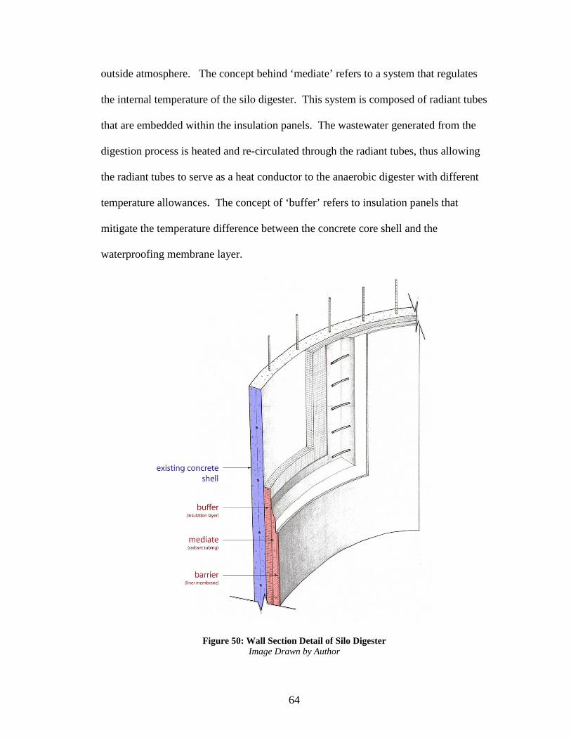
tolerate the bitterly cold winter seasons that Buffalo, New York endures. The layers
of insulation within a silo digester can be broken down into three functions: barrier,
mediate, and buffer (see Figure 50). The concept of ‘barrier’ refers to a thin water-
proofing membrane layer that seals the inside environment of the digester from the
64
outside atmosphere. The concept behind ‘mediate’ refers to a system that regulates
the internal temperature of the silo digester. This system is composed of radiant tubes
that are embedded within the insulation panels. The wastewater generated from the
digestion process is heated and re-circulated through the radiant tubes, thus allowing
the radiant tubes to serve as a heat conductor to the anaerobic digester with different
temperature allowances. The concept of ‘buffer’ refers to insulation panels that
mitigate the temperature difference between the concrete core shell and the
waterproofing membrane layer.
Figure 50: Wall Section Detail of Silo Digester Image Drawn by Author

65
By converting existing concrete grain silos into functioning anaerobic
digesters that process waste, this thesis presents the question of ‘how will waste be
distributed into the confines of each silo digester?” At the scale of the building, waste
inflow will ultimately mimic the same flow patterns as that of a typical grain elevator.
Waste inflow will initially need to be elevated off the ground plane, and then
distributed horizontally along the level of the bin floor before being deposited into a
silo digester (see Figure 51). Compared to the conventional flow patterns of how
grain is initially elevated in a workhouse by means of a vertical conveyor system, the
initial inflow of waste will be different by requiring a pump system to provide the
vertical distribution of waste. For the proposed intervention of the American
Elevator, there are three different program layouts in section for the building: waste
discharge on the lower gallery level, waste digestion on the bin floor level, and gas
collection on the upper gallery level (see Figure 52). The rectangular steel framed
building element located between the original bin network and annex is utilized as a
pumphouse, responsible for the vertical distribution of waste.
Figure 51: Diagram of Waste and Gas Flow Image Drawn by Author
66
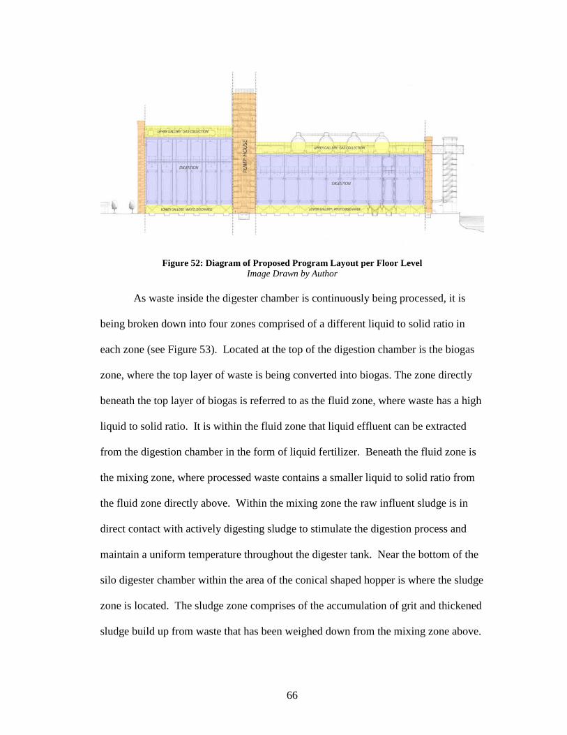
Figure 52: Diagram of Proposed Program Layout per Floor Level Image Drawn by Author
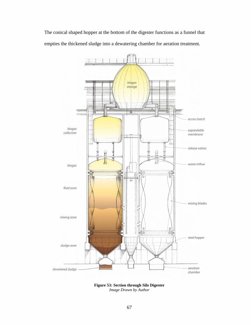
As waste inside the digester chamber is continuously being processed, it is
being broken down into four zones comprised of a different liquid to solid ratio in
each zone (see Figure 53). Located at the top of the digestion chamber is the biogas
zone, where the top layer of waste is being converted into biogas. The zone directly
beneath the top layer of biogas is referred to as the fluid zone, where waste has a high
liquid to solid ratio. It is within the fluid zone that liquid effluent can be extracted
from the digestion chamber in the form of liquid fertilizer. Beneath the fluid zone is
the mixing zone, where processed waste contains a smaller liquid to solid ratio from
the fluid zone directly above. Within the mixing zone the raw influent sludge is in
direct contact with actively digesting sludge to stimulate the digestion process and
maintain a uniform temperature throughout the digester tank. Near the bottom of the
silo digester chamber within the area of the conical shaped hopper is where the sludge
zone is located. The sludge zone comprises of the accumulation of grit and thickened
sludge build up from waste that has been weighed down from the mixing zone above.
67
The conical shaped hopper at the bottom of the digester functions as a funnel that
empties the thickened sludge into a dewatering chamber for aeration treatment.
Figure 53: Section through Silo Digester Image Drawn by Author

68
The three types of floor plans for the proposed building intervention of the
American elevator are: lower gallery for waste discharge, bin floor for waste
digestion, and upper gallery for gas collection (see Figure 55). At the level of the
lower gallery, processed waste is discharged into a conical shaped steel hopper that
funnels the waste into an aeration chamber that is located beneath each silo. The
aeration chambers are interconnected to one another by air-sealed pump lines that
recirculate processed waste back to the main pump house for further distribution. The
bin floor is comprised of added parts and elements of new technology that make up
the digesters within the shell of each concrete silo. With the insertion of new
technology, the bin floor utilizes the full height of the existing concrete silo shell for
the waste treatment process. Located above the bin floor level is the upper gallery,
where gas collection tanks are located to provide storage chambers for the produced
biogas. Laboratories, classrooms, and building control rooms are additional program
elements that have been added to the upper gallery floor level (see Figure 54).
Figure 54: Program Distribution on Upper Gallery Floor Level Image Drawn by Author

69
Figure 55: Plan Drawings of Repurposed American Elevator Complex Image Drawn by Author

70
Figure 56: Section to Elevation Drawing Image Drawn by Author

71
Figure 57: Proposed Site Plan of Childs Street Industrial Complex Image Drawn by Author
Anaerobic digestion is part of a five step wastewater treatment process. In
order of sequence, the five steps of wastewater treatment are: screening,
sedimentation, aeration, purification, and digestion. The proposed site plan of the
Childs Street Industrial Complex is programmed around the required steps to
complete the wastewater treatment process (see Figure 57). In order to supply raw

72
waste in the form of feedstock to the silo digesters located in the American Elevator,
wastewater must first undergo primary and secondary treatment. Primary and
secondary wastewater treatment screen out large inorganic contaminates, and reduce
the levels of liquid effluent by diluting water molecules from the concentrations of
more solid based raw waste. The primary responsibility of digestion in the overall
wastewater treatment process is to break down and decompose organic matter, and
not aid in the wastewater treatment process.

73
Figure 58: Waste Flow Diagram of Wastewater Treatment
Image Drawn by Author Understanding how waste flow is distributed over the course of the building is
similar to the way grain was previously distributed in the American Elevator. Either
by barge, rail, or truck, the inflow of waste is initially stored in a collection pit at the
bottom of the pumphouse. There are four pump lines that then elevate the waste from
the pit in a vertical direction. Once elevated above the level of the silo digesters,
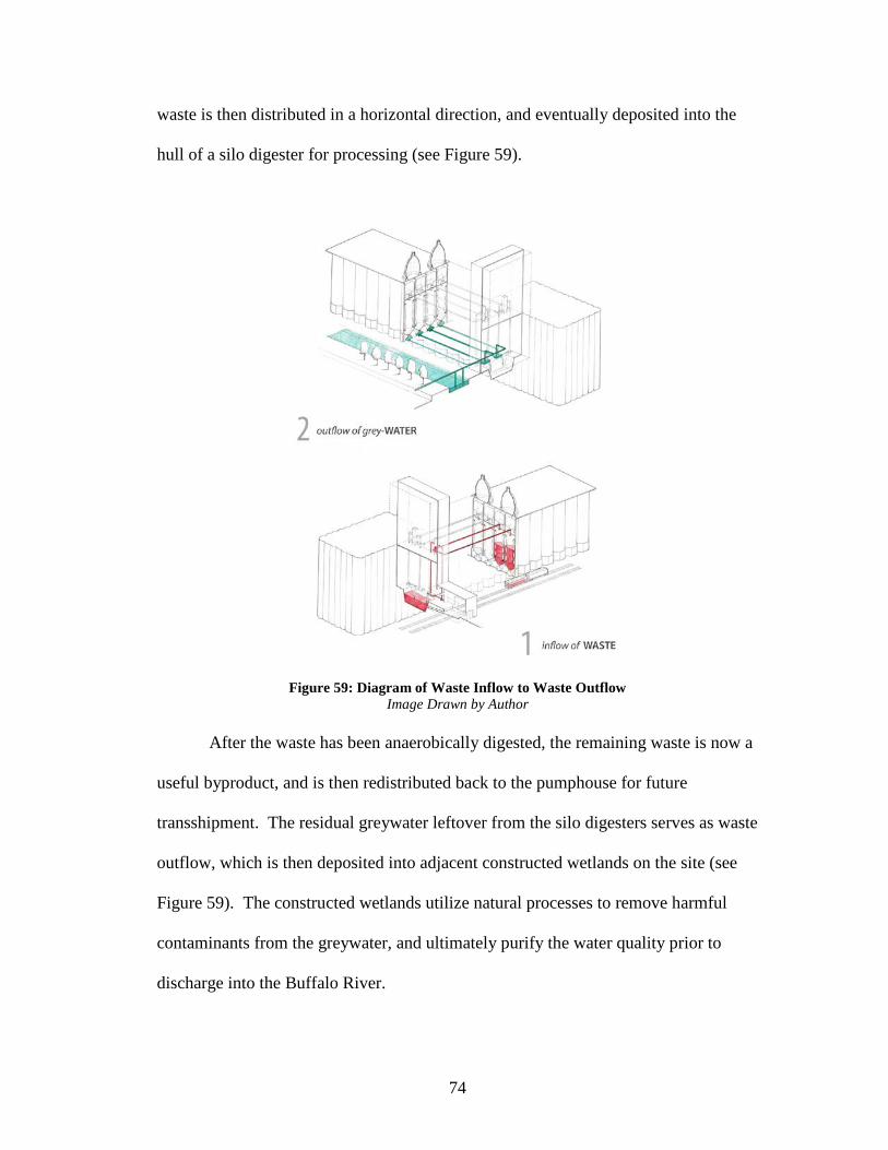
74
waste is then distributed in a horizontal direction, and eventually deposited into the
hull of a silo digester for processing (see Figure 59).
Figure 59: Diagram of Waste Inflow to Waste Outflow Image Drawn by Author
After the waste has been anaerobically digested, the remaining waste is now a
useful byproduct, and is then redistributed back to the pumphouse for future
transshipment. The residual greywater leftover from the silo digesters serves as waste
outflow, which is then deposited into adjacent constructed wetlands on the site (see
Figure 59). The constructed wetlands utilize natural processes to remove harmful
contaminants from the greywater, and ultimately purify the water quality prior to
discharge into the Buffalo River.

75
The final transformation of the American Elevator is an additive process
composed of three distinct building elements: workhouses, top deck, and gas
collection tanks (see Figure 60). The workhouses are inserted at the end bay
conditions of both the original silo network and annex, with internal pump lines that
distribute waste flow in a vertical direction. The main workhouse is located in
between the original bin network and annex. The workhouses function as vertical
circulation shafts for building occupants, and also provide scaffolding that
structurally supports the vertical pump lines. The top deck is an elevated platform
supported by the shell walls of the concrete silos below. Laboratories, classrooms,
and operational control offices are located along the top deck, and all connected by a
central corridor that parallels the length of the building along the centerline. Bearing
on the slab of the top deck are gas collection tanks, which are uniformly positioned in
relationship to the grid layout of concrete silo bins below.

76
Figure 60: Exploded Axonometric Diagram of Additive Building Elements Image Drawn by Author
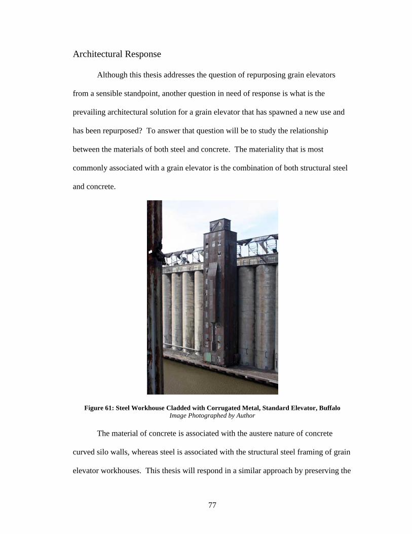
77
Architectural Response
Although this thesis addresses the question of repurposing grain elevators
from a sensible standpoint, another question in need of response is what is the
prevailing architectural solution for a grain elevator that has spawned a new use and
has been repurposed? To answer that question will be to study the relationship
between the materials of both steel and concrete. The materiality that is most
commonly associated with a grain elevator is the combination of both structural steel
and concrete.
Figure 61: Steel Workhouse Cladded with Corrugated Metal, Standard Elevator, Buffalo Image Photographed by Author
The material of concrete is associated with the austere nature of concrete
curved silo walls, whereas steel is associated with the structural steel framing of grain
elevator workhouses. This thesis will respond in a similar approach by preserving the

78
same inherent relationship between the material use of both steel and concrete. Steel
will be utilized to provide the structural framework for the pumphouse, and concrete
along the face of silo walls will be preserved and unaltered. Typically, a grain
elevator workhouse is cladded with corrugated metal panels that wrap the building,
and conceal the structural frame (see Figure 61). The proposed pumphouse, which
operates similar in principal to that of a grain elevator workhouse, is cladded with
glass to express the structural steel framework. By cladding the pumphouse with
glass, a contrasting relationship is established between the austere nature of the
concrete curved silo walls against the light delicate nature of structural steel framing.
The material relationship of both steel and concrete is also in contrast to one
another by the use of ‘wall.’ When proposing an architectural response, the idea of
‘wall’ is thought of as a vertical plane that separates rooms, spaces, environments,
and even atmospheres. A wall can rise to a defined or implied height, and still
function and hold true to its meaning even if it is transparent. In the proposed
architectural response for the American Elevator, the concrete silo walls are left solid,
and the glass curtain walls of the pumphouse are transparent. Structure is expressed
and held truthful to form by maintaining a continuous uninterrupted wall surface
along the face of the concrete silos. Contrary to the walled nature of concrete silos,
the structure of the pumphouse is expressed by the linear elements that make up the
structural framing and lateral bracing. The exterior walls of the pumphouse function
as a transparent plane that establishes a visual link connecting the internal program to
the outside environment. As a result, the pumphouse introduces a relationship
between the inside and outside environments, whereas the walls of the concrete silos

79
deny any visual relationship to occur between the internal silo digesters and the
outdoor environment.
Figure 62: Main Elevation of Proposed Pumphouse Image Drawn by Author
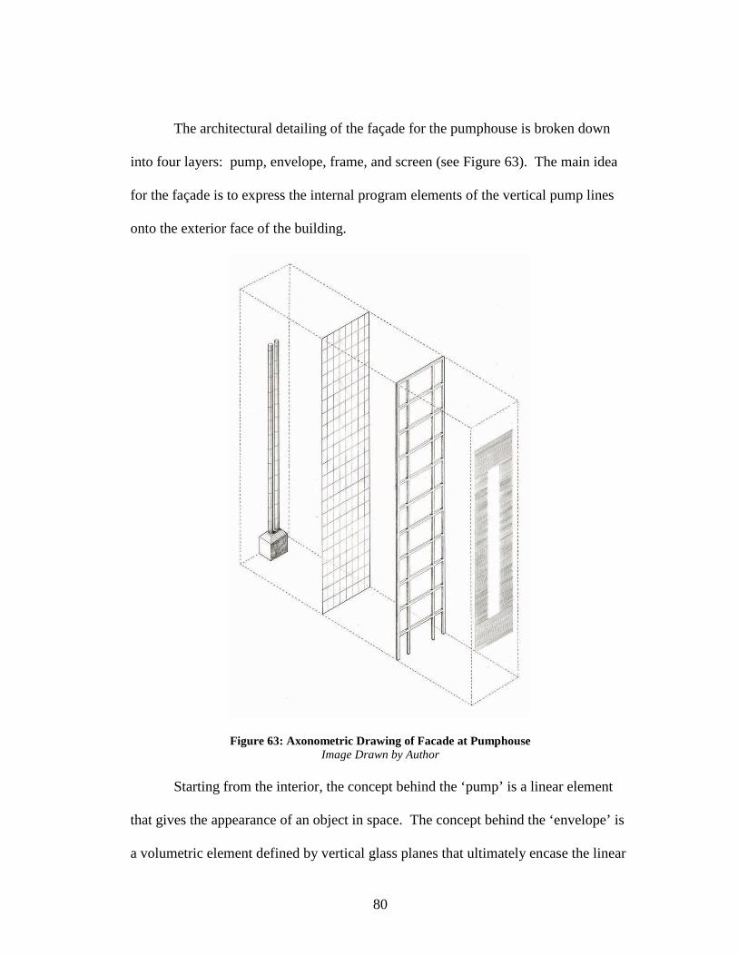
80
The architectural detailing of the façade for the pumphouse is broken down
into four layers: pump, envelope, frame, and screen (see Figure 63). The main idea
for the façade is to express the internal program elements of the vertical pump lines
onto the exterior face of the building.
Figure 63: Axonometric Drawing of Facade at Pumphouse Image Drawn by Author
Starting from the interior, the concept behind the ‘pump’ is a linear element
that gives the appearance of an object in space. The concept behind the ‘envelope’ is
a volumetric element defined by vertical glass planes that ultimately encase the linear

81
element of the pump-line as an object in open space. The concept behind the ‘frame’
references a grid composed of structural steel columns and beams. The structural
framework of the columns and beams add a layer of depth to the façade by sitting
proud of the glass envelope, but also providing an element of scale by distinguishing
floor to ceiling heights (see Figure 64).
Figure 64: Elevation Detail of Pumphouse Image Drawn by Author
The outermost layer of the façade is the ‘screen’, which is a continuous
vertical plane that runs up the face of the building, primarily functioning as a rain
screen and sun shading device. The screen is composed of individual horizontal
louvers that mediate the amount of direct sun exposure the pumphouse receives.
From the main elevation, the screen wall of horizontal louvers frame a void around
the centerline of the internal vertical pump lines, which reinforces the idea of the
vertical pump lines serving as an object in space.
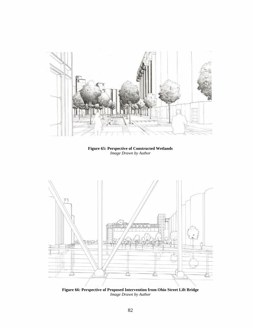
82
Figure 65: Perspective of Constructed Wetlands Image Drawn by Author
Figure 66: Perspective of Proposed Intervention from Ohio Street Lift Bridge
Image Drawn by Author

83
Conclusion
The big underlining question of this thesis is: what is a sensible response to
repurposing and reusing an abandoned grain elevator? Does it make sense to restore
abandoned grain elevators by converting them into loft apartments for people to
occupy? Would it be more economical to minimize the amount of transformation and
intervention if the grain elevators of Buffalo could only be served as industrial
artifacts from a bygone age? Or is the only solution to repurposing the grain
elevators along the Buffalo River is to convert the silos into storage containers that
process and treat waste? There are many theories that can be conceived of, but there
is no prescribed solution for the sensible reuse of the grain elevator typology. The
grain elevator is a typology that is strictly designed for one purpose: the storage and
distribution of grain. The grain elevators of Buffalo symbolize cathedrals of wealth
the American economy possesses, and how much grain is ultimately consumed in the
process of feeding a country.
If hypothetically the grain elevators of Buffalo were successfully transformed
and repurposed into functioning waste treatments facilities that yield renewable
energy and produce byproducts, the typology of the grain elevator will inherit a new
meaning. Once representing enormous storage containers symbolizing consumption,
grain elevators will be given a rebirth to their meaning, and symbolize as a catalyst to
production. If silo digesters are the cure to a rather infectious disease of the derelict
grain elevators of Buffalo, then the theory behind the proposal is ‘industrializing a
natural waste treatment process’ (see Figure 67). New meaning and program is given

84
to a depreciated typology of the grain elevator by infusing new technology into the
hull of empty concrete silos.
Figure 67: Hybrid Drawing of Silo Digester Image Drawn by Author

85
Figure 68: Typical Grain Silo Configuration (right) Figure 69: Honeycomb Network
Nature has essentially provided the blueprint of design for storage vessels that
are arranged in an interconnected network of cellular like spaces and modules.
Humans are not the only species that are considered habitat building. There are
existing patterns and structures found in nature that mimic the same principal in
structure to that of a network of concrete grain silos constructed by mankind. How a
typical arrangement of grain silos are interconnected to one another resembles the
same natural pattern of the honeycomb (see Figure 68). The theory of this thesis is to
propose a new building use of existing grain silos, in which the prevailing building
use is similar in function to the original use. It is important to remember that grain
silos are nothing more than storage containers. Grain silos do not garner the
responsibility of providing inhabitable space. Grain silos are not known for their
unique spatial quality of tall dark cylindrical spaces. On the contrary, grain silos are
known for their vastness in storage capacity and load bearing capabilities of a
supplied substance. This thesis investigates and proposes a new method for design
that responds in a sensible manner to the unique inherent properties of the grain silo.
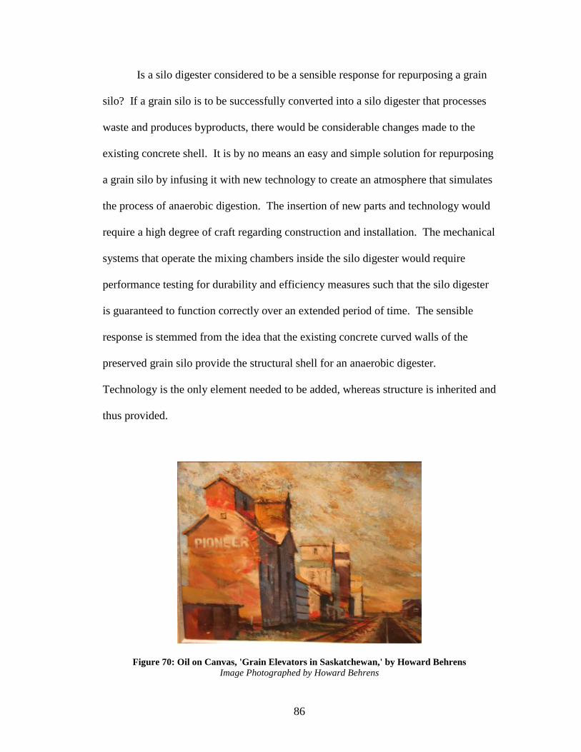
86
Is a silo digester considered to be a sensible response for repurposing a grain
silo? If a grain silo is to be successfully converted into a silo digester that processes
waste and produces byproducts, there would be considerable changes made to the
existing concrete shell. It is by no means an easy and simple solution for repurposing
a grain silo by infusing it with new technology to create an atmosphere that simulates
the process of anaerobic digestion. The insertion of new parts and technology would
require a high degree of craft regarding construction and installation. The mechanical
systems that operate the mixing chambers inside the silo digester would require
performance testing for durability and efficiency measures such that the silo digester
is guaranteed to function correctly over an extended period of time. The sensible
response is stemmed from the idea that the existing concrete curved walls of the
preserved grain silo provide the structural shell for an anaerobic digester.
Technology is the only element needed to be added, whereas structure is inherited and
thus provided.
Figure 70: Oil on Canvas, 'Grain Elevators in Saskatchewan,' by Howard Behrens Image Photographed by Howard Behrens

87
Process Drawings
Figure 71: Development of Section Drawings of Silo Digester Image Drawn by Author
Figure 72: Aerial of Constructed Wetlands adjacent to American Elevator Image Drawn by Author

88
Figure 73: Process Elevation Bay Drawing with Digester Section Image Drawn by Author

89
Figure 74: Process Elevation to Section Drawing Image Drawn by Author

90
Figure 75: Process Building Elevations Image Drawn by Author
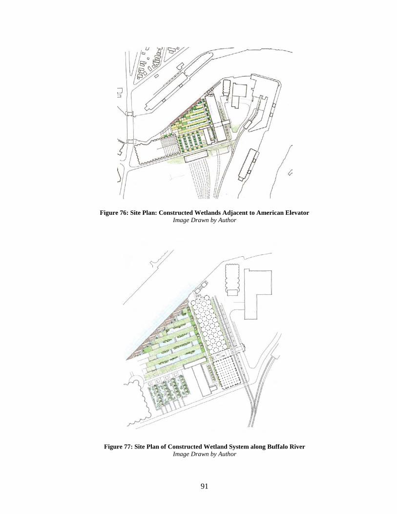
91
Figure 76: Site Plan: Constructed Wetlands Adjacent to American Elevator Image Drawn by Author
Figure 77: Site Plan of Constructed Wetland System along Buffalo River Image Drawn by Author

92
Bibliography 1. William Cronon, Nature’s Metropolis: Chicago and the Great West (W.W. Norton, 1992), p.111.
2. Lewis Mumford, Technics and Civilization (Hardcourt, Brace and World, 1934), pp. 192, 437-446.
3. Francis R. Kowsky, Monuments of a Vanished Prosperity: Buffalo's Grain Elevators and the Rise and Fall of the Great Transnational System of Grain Transportation (Published in Reconsidering Concrete Atlantis: Buffalo Grain Elevators. L. Schneekloth, 2006). 4. Reyner Banham, A Concrete Atlantis, pp. 110-111)
5. Lauren Makeyenko, Energy Efficiency and Enhancements at Tifft Nature Preserve (Green Renaissance of Western New York, April, 2012).
6. Thomas Sieverts, Cities without Cities: An Interpretation of the Zwischenstadt. (London & New York: Spon Press, 2003).
7. Fredric Jameson, Postmodernism or, the Cultural Logic of Late Capitalism. (NC: Duke University Press, 1991). 8. J Handley, The Post Industrial Landscape. (The Groundwork Foundation: Birmingham, 1996). 9. Paul Drury, The Historic and Cultural Dimensions of Landscape. Naturopa, No.98 (Belgium: Bietlot Gilly, 2002) pp.12-13. 10. Marc Antrop, Why Landscapes of the Past are Important for the Future. Landscape and Urban Planning, vol. 70 (Belgium: Ghent University, 2000). 11. Donald Meinig, The Interpretation of Ordinary Landscapes: Geographical Essays. (Oxford: Oxford University Press, 1979). 12. Latz and Latz, 2001:73 13. California Integrated Waste Management Board, Current Anaerobic Digestion Technologies Used for Treatment of Municipal Organic Solid Waste (March 2008), pp. 1-2. 14. National Non-Food Crops Centre, NNFCC Renewable Fuels and Energy Factsheet: Anaerobic Digestion (November, 2011), pp. 1-2.

93
15. United States Department of Energy, How Anaerobic Digestion (Methane Recovery) Works (August 2007). 16. WRAP, Using Quality Anaerobic Digestate to Benefit Crops (Summer 2012), pp 3-4. <http://www.wrap.org.uk/sites/files/wrap/Using%20quality%20digestate%20t o%20benefit%20crops.pdf>