Embed Size (px)
Citation preview

Integrated Sensor Technologies Preventing Accidents Due to
Driver Fatigue
Carl Tenenbaum David Haynes Philip Pham Rachel Wakim
Introduction to Biosensors (16.541)
University of Massachusetts at Lowell
1 Abstract
Today’s cars have integrated sensors, central processing units, integrated wireless communications and
automated controls. This paper looks at combining these technologies, with additional biosensor
technology to monitor the driver’s behaviors to prevent vehicle accidents. The paper takes the SPA
(Sense, Process, & Act) model of analyzing the issue.
According to Sixwise.com, the majority of car accidents are caused by drivers being distracted or driver
fatigue. [1] Twelve percent of the drivers distracted report fatigue issues causing this problem. This paper
takes the approach of solving these concerns by looking at the technologies that can detect fatigued
driving through sensors and post processing. The sensor technologies that detect the driver’s fatigue
condition use either the driver’s optical behaviors or biometric signatures. In addition to be able to detect
a fatigued driver, an approach needs to be devised to respond to this issue to prevent an accident that may
harm the driver, car occupants, or external pedestrians.
2 Introduction
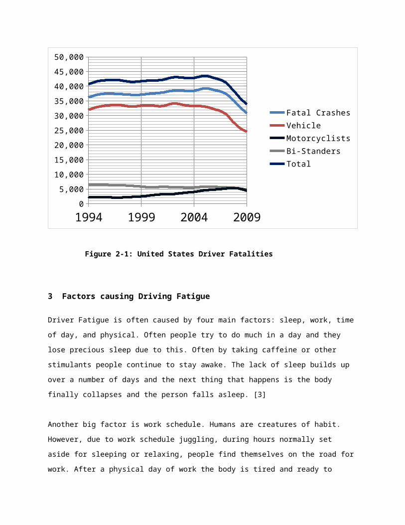
According to the National Highway Traffic Safety Administration (NHTSA) there were 33,808 vehicle
causalities in 2009. Figure 2-1 breaks down the driver fatalities according to NHTSA. In comparison, the
combined causalities total for both Operation Iraqi Freedom and Operation Enduring Freedom
Afghanistan is currently 7094 casualties since 2001 according to icasualties.org. That means there is a
five times greater chance of death associated with driving under the presumably less hostile roads of the
Unites States in a one year period compared to ten years of the Operation Freedoms across the world on
roads full of Improvised Explosive Devises (IEDs) in hostile territories.
The NHTSA estimates that over 56,000 police-reported accidents are due to driver fatigue. This results in
1600 deaths, 71,000 injuries and 12.5 billion dollars monetary loss. [2] This is conservative due to the fact

that it is difficult to properly estimate how many accidents were really caused by driver fatigue.
According to police, a fatigued driver will exhibit the same behavior as a drunk driver: slow reaction
times, swerving between lanes, and unintentionally speeding or slowing down. [3] Yet, there is no law for
driving fatigued and often the driver does not realize how fatigued they are until it is too late. This paper
will examine the behaviors of driver fatigue, ways to monitor the behavior, techniques to integrate a
control to prevent and notify the vehicle driver of their behavior, and decisions to be made to the vehicle
if the driver fails to act when in this condition.
1994 1999 2004 20090
5,000
10,000
15,000
20,000
25,000
30,000
35,000
40,000
45,000
50,000
Fatal CrashesVehicleMotorcyclistsBi-StandersTotal
Figure 2-1: United States Driver Fatalities
3 Factors causing Driving Fatigue
Driver Fatigue is often caused by four main factors: sleep, work, time of day, and physical. Often people
try to do much in a day and they lose precious sleep due to this. Often by taking caffeine or other
stimulants people continue to stay awake. The lack of sleep builds up over a number of days and the next
thing that happens is the body finally collapses and the person falls asleep. [3]
Another big factor is work schedule. Humans are creatures of habit. However, due to work schedule
juggling, during hours normally set aside for sleeping or relaxing, people find themselves on the road for
work. After a physical day of work the body is tired and ready to relax. The driver puts the air conditioner
on and listens to some soothing music, and the next thing that happens is the driver is in a vulnerable
position to be distracted due to fatigue.
Time of day factors can often affect the body. The human brain is trained to think there are times the body
should be asleep. These are often associated with seeing the sunrise and sunset. Between the hours of 2
AM and 6 AM, the brain tells the body it should be asleep. Extending the time awake will eventually lead
to the body crashing.
The final factor is a person’s physical condition. People sometimes are on medications that create
drowsiness or have physical ailments that cause these issues. Being physically unfit, by being either under
or overweight, will cause fatigue. Additionally, being emotionally stressed will cause the body to get
fatigued quicker.
4 Background of Detection of Fatigue
If car technologies are going to prevent or at least warn of driver fatigue, what symptoms does the driver
give off that can be detected? According to research, there are multiple categories of technologies that
can detect driver fatigue. The first is the use of cameras to monitor a person’s behavior. This includes
monitoring their pupils, mouth for yawning, head position, and a variety of other factors. The next of
these technologies is voice recognition. Often a person’s voice can give off clues on how fatigued they
are. The next technology is the ability to person’s learned driving behavior to determine if the person is
deviate from their normal behavior. Another technology is measure the person’s head angle. This is
relative cheap scheme that uses basic devices. The final of these technologies is the biometrics the person
gives off. A person’s blood pressure, body impedance, and pulse, as well a variety of vitals, will change if
they are fatigued.
The question to be examined in this paper is which of the technologies are the most reliable. Additionally,
even if the technology is reliable enough to be accepted by the driver, it has to be non-intrusive to the way
the driver feels comfortable. Finally, the cost to implement the technology is critical if it is going to be
accepted.
5 Sensor Technology and Automobile Integration
Integrating sensor systems into modern cars requires more than breakthrough technology; for any new
system to thrive past infancy, it needs to be accepted into the market quickly. What would convince a
consumer to spend extra money on a new auto safety feature? To be appealing enough, we propose that a
new sensor system must have at least the following qualities:
It must be accurate.
It must have a fairly quick response time, which could be the difference between a near-miss and
a tragic fatality.
It must be relatively inexpensive.
It must either be already integrated in the car design, or effortlessly adaptable, a la “plug and
play.”
It must be discreet and noninvasive; a sensor that annoys the driver could potentially worsen the
problem of distracted driving.
It must be adaptable to changes in driver attire, driver position, and driver style.
It must work with multiple users, as many different people may drive the same car.
Since the problem of drowsy driving is often not taken as seriously as other driving problems such as
drunk driving, making these systems appealing enough for the extra cost will likely be difficult. Extra
steps need to be taken to educate the public about the reality of drowsy driving and the importance of
monitoring a driver’s condition.
Multiple methods of integrating biosensors into automobiles are currently in study, and have been for
over a decade. As described in Section 4, there are four approaches to the detection of driver fatigue:
Optical, Voice, Behavioral, and Biometric monitoring and analysis. Each method has obvious advantages
and disadvantages that are the subject of ongoing research. Examples of some technologies are listed in
the following sections.
5.1 Audio Detection
Currently most drivers do little talking in their car unless there are other passengers, but as car
technologies and cell phones become more integrated in automobiles, this field could potentially be used.
The way audio detectors work is by storing voice responses of the driver and using them as comparisons
to determine is the person is fatigued. Figure 5-2 depicts the Flow Chart of an Audio Detection.

Figure 5-2: Audio Detection Flow Chart
Human voice is typically in the frequencies of 300 Hz to 3.4 KHz as shown in Figure 5-3. The vocal tract,
which forms the resonance tube in the speech production, system mainly, consists of pharynx, nasal
cavity and oral cavity. Articulation is the process of shaping the vocal tract to produce different sounds.
Speech sounds can be classified into four types; voiced sounds, fricative sounds, plosive sounds and nasal
sounds. Plosive sounds are produced when the oral cavity closes (i.e., the mouth is shut). Air pressure
builds up behind the closure and the air is suddenly released, producing such sounds as “d,” “g,” “p” and
“t”. As a person becomes fatigue the sounds most affected are the plosive sounds . Additionally, the length
of each word and the latency between words becomes longer as a person tires. By using voice quality
filters, software can detect the change in voice and assign voice based on the difference from earlier
detected parameters. [4]
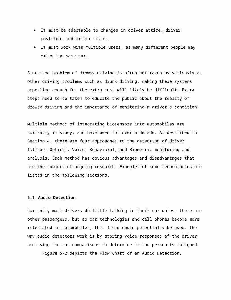
Figure 5-3: Voice Channel
Since we are focusing on passive systems we will note that voice analysis requires the driver to be
actively speaking while driving and we will spend more time focusing on the passive systems of Optical,
Behavioral and Biometric detection.
5.2 Head Nodding Detection
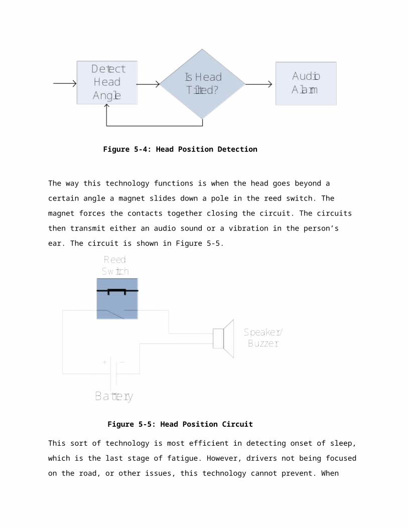
Another method currently use is the Head Position Detection. This technology simply determines the
head tilt angle. When the head angle goes beyond a certain angle, an audio alarm is transmitted in the
driver’s ear.
depicts the flow chart of the Head Angle Detector.
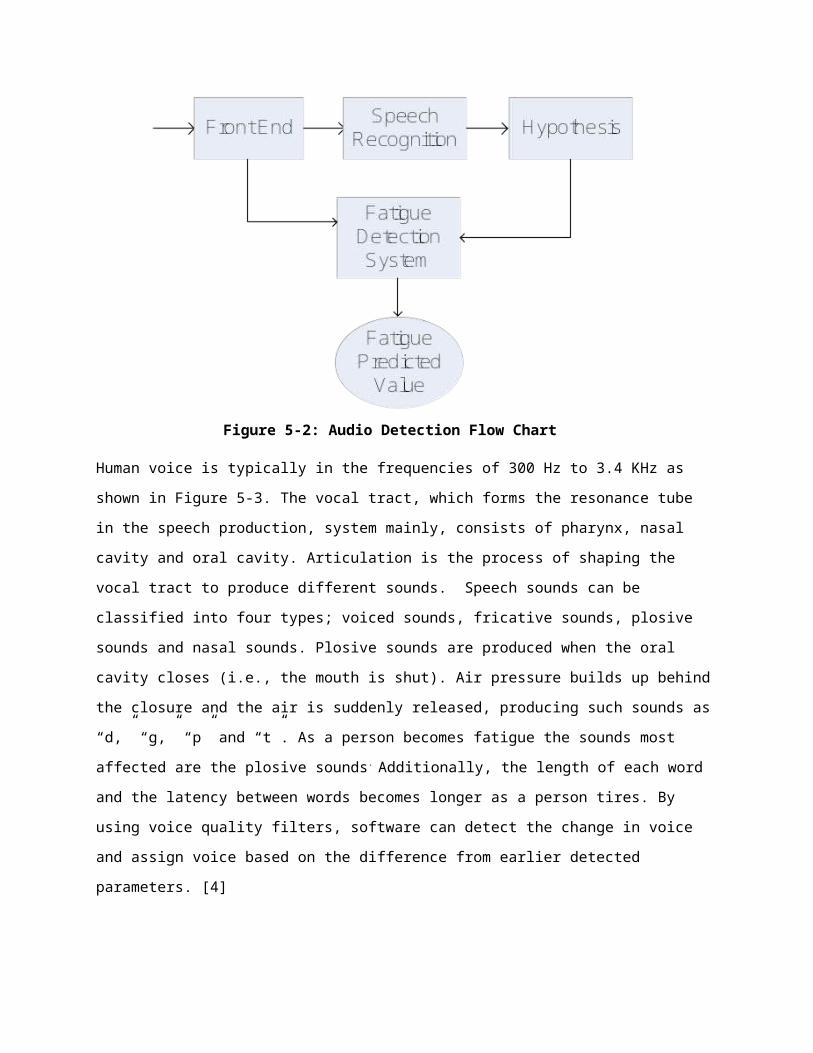
Figure 5-4: Head Position Detection
The way this technology functions is when the head goes beyond a certain angle a magnet slides down a
pole in the reed switch. The magnet forces the contacts together closing the circuit. The circuits then
transmit either an audio sound or a vibration in the person’s ear. The circuit is shown in Figure 5-5.
Figure 5-5: Head Position Circuit
This sort of technology is most efficient in detecting onset of sleep, which is the last stage of fatigue.
However, drivers not being focused on the road, or other issues, this technology cannot prevent. When
drivers are in a fatigued position they are extremely vulnerable and the onset of sleep is too late. This
technology was not researched any further due to its limited effectiveness.

5.3 Driver Behavior Detection
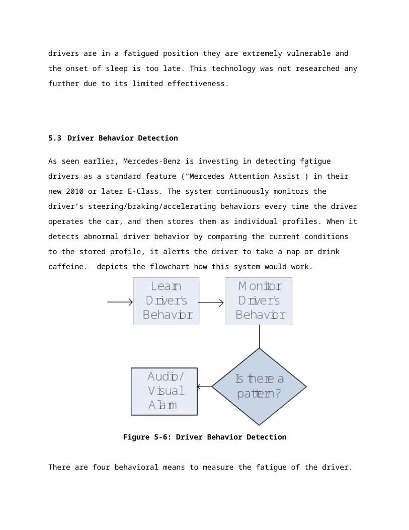
As seen earlier, Mercedes-Benz is investing in detecting fatigue drivers as a standard feature (“Mercedes
Attention Assist”) in their new 2010 or later E-Class. The system continuously monitors the driver’s
steering/braking/accelerating behaviors every time the driver operates the car, and then stores them as
individual profiles. When it detects abnormal driver behavior by comparing the current conditions to the
stored profile, it alerts the driver to take a nap or drink caffeine. depicts the flowchart how this system
would work.
Figure 5-6: Driver Behavior Detection
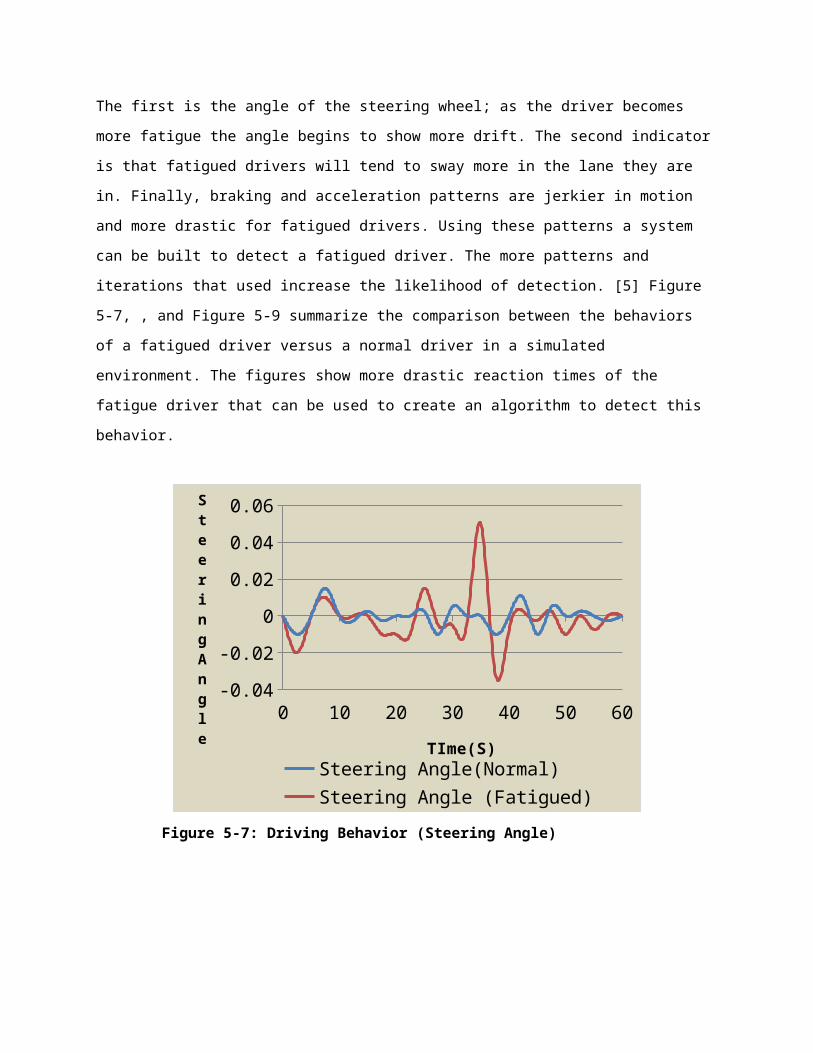
There are four behavioral means to measure the fatigue of the driver. The first is the angle of the steering
wheel; as the driver becomes more fatigue the angle begins to show more drift. The second indicator is
that fatigued drivers will tend to sway more in the lane they are in. Finally, braking and acceleration
patterns are jerkier in motion and more drastic for fatigued drivers. Using these patterns a system can be
built to detect a fatigued driver. The more patterns and iterations that used increase the likelihood of
detection. [5] Figure 5-7, , and Figure 5-9 summarize the comparison between the behaviors of a fatigued
driver versus a normal driver in a simulated environment. The figures show more drastic reaction times of
the fatigue driver that can be used to create an algorithm to detect this behavior.
0 10 20 30 40 50 60-0.04
-0.02
0
0.02
0.04
0.06
Steering Angle(Normal)Steering Angle (Fatigued)
TIme(S)
SteeringAngle
Figure 5-7: Driving Behavior (Steering Angle)
0 10 20 30 40 50 600
0.10.20.30.40.5
Gas Pedal (Normal) Gas Pedal (Fatigued)Time (S)
Gas Pedal Depth
Figure 5-8: Driving Behavior (Gas Pedal Acceleration)
0 10 20 30 40 50 600
0.51
1.52
2.53
Distance to Center Lane (Normal)Distance to Center Lane (Fatigued)
Time(S)
Meters
Figure 5-9: Driving Behavior (Distance to Center Lane)
Steering Angle Sensor
The sensor is mounted directly on the steering shaft to measure the steering wheel angle and the number
of steering wheel rotations. The steering angle sensor is basically made up of a resistance circuit and two
wipers (potentiometers or non-contact optical technology) offset by 90O. A non-interrupted power supply
is fed to the steering angle sensor so the angle of the steering wheel is always available to the control unit
even when the car’s ignition is off. The change in steering wheel angle and the frequency of movement
will be calculated to determine if there is a fatigue condition.
A minor inconvenience is that the steering angle sensor needs to be calibrated with proper equipment
whenever a new sensor is replaced and the steering wheel or front suspension is serviced. The cost to
replace a new steering angle sensor is around $600-$700 including labor.
Video, Laser, and Infrared Sensors
These sensors are integrated in some cars to warn the driver when the vehicle starts drifting with audible,
visual, and vibration feedback. The video sensors mounted on rearview mirror, laser sensors mounted in
the vehicle front, and infrared sensors installed under the vehicle constantly monitor the lane markings
and the vehicle speed. The information will be analyzed and the corrective actions of warnings (Lane
Departure Warning, LDW) or assisting (Lane Keeping Assist, LKA) will depend on the manufacturers’
proprietary technologies. The combination of those safety features will increase the chance to avoid an
accident.
Currently, these features are only available to high-end vehicles from Cadillac, Lexus, BMW, Volvo,
Audi, and Mercedes-Benz.
5.4 Optical Detection
The most common implementation of an optical sensor system uses infrared or near-infrared LEDs to
light the driver’s pupils, which are then monitored by a camera system. Computer algorithms analyze
blink rate and duration to determine drowsiness. The camera system may also monitor facial features and
head position for signs of drowsiness, such as yawning and sudden head nods. Figure 5- depicts the use of
an optical detection system.

Figure 5-9: Optical Detection
Perhaps the most important element in optical detection is pupil detection and tracking. One effective
method uses a low-cost charge-coupled device (CCD) micro camera sensitive to near infrared light with
near-infrared LEDs for pupil illumination. Pupil detection is simplified by the “bright pupil” effect,
similar to the red-eye effect in flash photography[6][9][10]. An embedded PC with a low-cost frame
grabber is used for the video signal acquisition and signal processing. The pupils are detected by
searching the entire image to locate two bright blobs that satisfy certain size and shape constraints. Once
the pupils are detected, information can be gathered relating to blink rate, blink duration, eye
closure/opening speed, and conditions such as eyes being not fully open. [7]
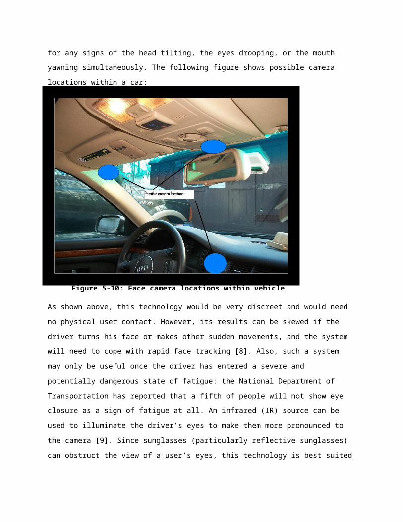
Such a system, mounted in a discreet corner of the car, could monitor for any signs of the head tilting, the
eyes drooping, or the mouth yawning simultaneously. The following figure shows possible camera
locations within a car:
Figure 5-10: Face camera locations within vehicle
As shown above, this technology would be very discreet and would need no physical user contact.
However, its results can be skewed if the driver turns his face or makes other sudden movements, and the
system will need to cope with rapid face tracking [8]. Also, such a system may only be useful once the
driver has entered a severe and potentially dangerous state of fatigue: the National Department of
Transportation has reported that a fifth of people will not show eye closure as a sign of fatigue at all. An
infrared (IR) source can be used to illuminate the driver’s eyes to make them more pronounced to the
camera [9]. Since sunglasses (particularly reflective sunglasses) can obstruct the view of a user’s eyes,
this technology is best suited for nighttime driving [8]. For cameras that track multiple visual cues,
however, even without view of the driver’s eyes, the system may be able to make a helpful prediction
based on head and mouth position. Some research has suggested that very subtle movements such as nose
wrinkling, chin rising, and jaw dropping, can also be used to predict a driver’s current state [12]. The
difficulty then, is in accurately tracking a user’s face.
Currently there are no commercially available cars with optical systems integrated, though there are a few
stand-alone cameras available that claim to be able to monitor a driver’s eyes for signs of drowsiness.
5.5 Biometric Detection
In addition to visual and behavioral cues, there are a number of biometric signs, or “vital signs”, given
when a person is falling asleep or even growing fatigued. One reliable method of determining a user’s
condition is to take an Electrocardiograph (“ECG” or “EKG” in English-speaking countries)
measurement. An EKG is a method by which the electric activity of the heart over time is measured by
electrodes placed on the skin. After isolation and amplification, this technique returns a continuous graph
of electric strength over time, as shown in Error: Reference source not found:
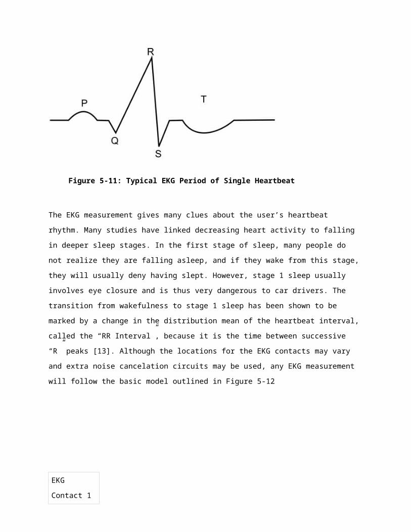
Figure 5-11: Typical EKG Period of Single Heartbeat
The EKG measurement gives many clues about the user’s heartbeat rhythm. Many studies have linked
decreasing heart activity to falling in deeper sleep stages. In the first stage of sleep, many people do not
realize they are falling asleep, and if they wake from this stage, they will usually deny having slept.
However, stage 1 sleep usually involves eye closure and is thus very dangerous to car drivers. The
transition from wakefulness to stage 1 sleep has been shown to be marked by a change in the distribution
mean of the heartbeat interval, called the “RR Interval”, because it is the time between successive “R”
peaks [13]. Although the locations for the EKG contacts may vary and extra noise cancelation circuits
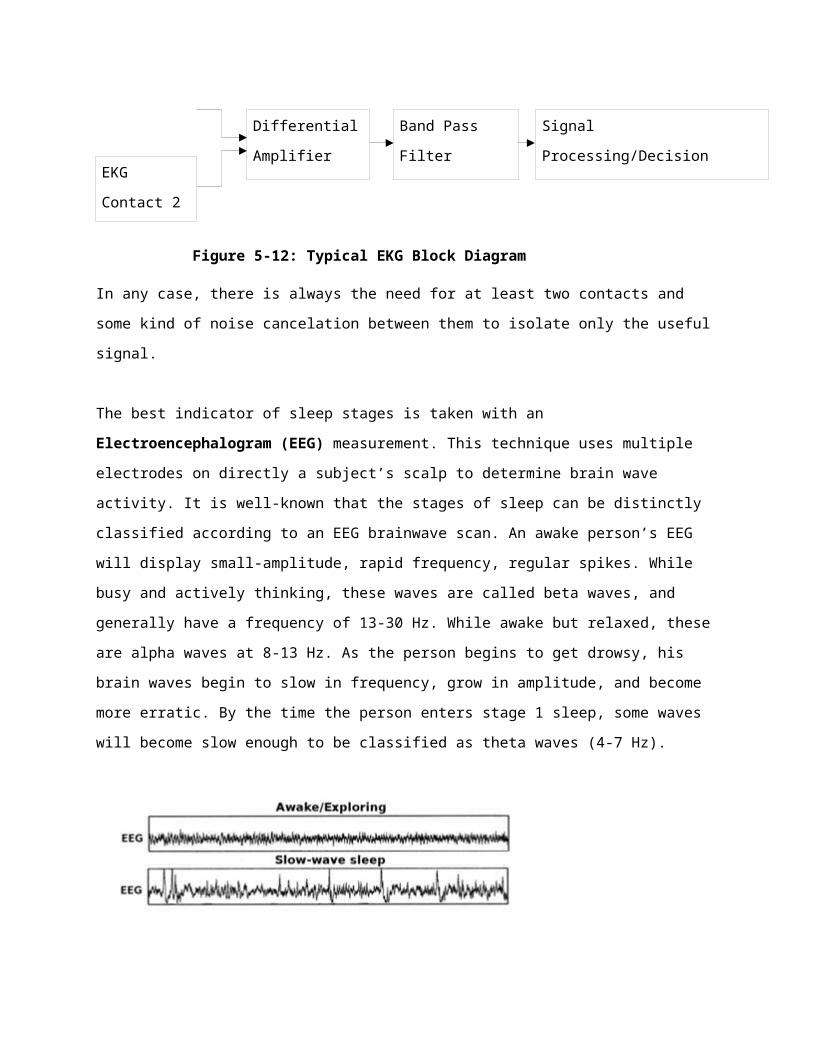
may be used, any EKG measurement will follow the basic model outlined in Figure 5-12

Figure 5-12: Typical EKG Block Diagram
In any case, there is always the need for at least two contacts and some kind of noise cancelation between
them to isolate only the useful signal.
The best indicator of sleep stages is taken with an Electroencephalogram (EEG) measurement. This
technique uses multiple electrodes on directly a subject’s scalp to determine brain wave activity. It is
well-known that the stages of sleep can be distinctly classified according to an EEG brainwave scan. An
awake person’s EEG will display small-amplitude, rapid frequency, regular spikes. While busy and
actively thinking, these waves are called beta waves, and generally have a frequency of 13-30 Hz. While
awake but relaxed, these are alpha waves at 8-13 Hz. As the person begins to get drowsy, his brain waves
begin to slow in frequency, grow in amplitude, and become more erratic. By the time the person enters
stage 1 sleep, some waves will become slow enough to be classified as theta waves (4-7 Hz).
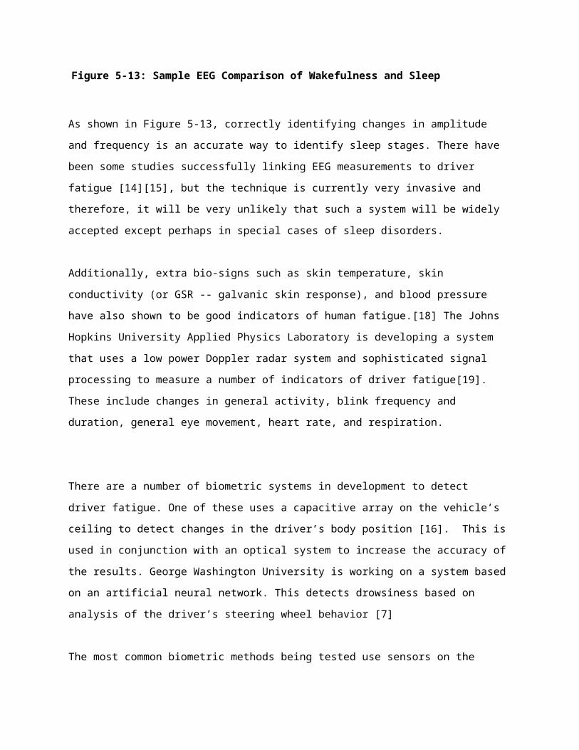
Figure 5-13: Sample EEG Comparison of Wakefulness and Sleep
As shown in Figure 5-13, correctly identifying changes in amplitude and frequency is an accurate way to
identify sleep stages. There have been some studies successfully linking EEG measurements to driver
fatigue [14][15], but the technique is currently very invasive and therefore, it will be very unlikely that
such a system will be widely accepted except perhaps in special cases of sleep disorders.
Additionally, extra bio-signs such as skin temperature, skin conductivity (or GSR -- galvanic skin
response), and blood pressure have also shown to be good indicators of human fatigue.[18] The Johns
EKG Contact
1
EKG Contact
2
Differential
Amplifier
Band Pass Filter Signal Processing/Decision Making
Hopkins University Applied Physics Laboratory is developing a system that uses a low power Doppler
radar system and sophisticated signal processing to measure a number of indicators of driver fatigue[19].
These include changes in general activity, blink frequency and duration, general eye movement, heart
rate, and respiration.
There are a number of biometric systems in development to detect driver fatigue. One of these uses a
capacitive array on the vehicle’s ceiling to detect changes in the driver’s body position [16]. This is used
in conjunction with an optical system to increase the accuracy of the results. George Washington
University is working on a system based on an artificial neural network. This detects drowsiness based on
analysis of the driver’s steering wheel behavior [7]
The most common biometric methods being tested use sensors on the either the steering wheel or driver’s
seat (or both) to take EKG signals and pressure measurements of heart rate variability and other factors to
indicate drowsiness[17][20][21][23].
A specific example of one system that has been tested uses sensors in both the seat and steering wheel.
The sensors in the seat use capacitively-coupled-electrodes while the steering wheel uses a direct contact
electrode. The steering wheel collects the signal ground from contact with the driver’s bare hand. Only
one hand contact is needed. The seat sensors collect the electrocardiogram (ECG) of the driver. The
sensors are placed under the buttocks for maximum contact pressure. A high-input impedance OP amp is
needed to boost the ECG signal to a useful level. This system produced accurate ECG results except
under the conditions of driving over bumpy roads or periods of driver body movement[20].
A sensor system can be integrated in the steering wheel that would be able to measure multiple factors
that can be used as a measure of drowsiness. These factors are divided into two categories: pressure
measurements such as grip force, pulse wave, and breathing wave, and electrical measurements like ECG
readings, skin conductance, and skin temperatures. To take ECG measurements, the sensors would take
the form of conductive fabric patches wrapped around the wheel, as shown:
Figure 5-14: Steering wheel sensor
Taking the bio-signs listed could give a very accurate assessment of the user because physical cues are
known to be a better indication of fatigue than visual cues, and they can be used in any light condition.
However, such a system would only work if the user was not wearing gloves and kept his hands in a
relatively constant position on the wheel; in some ECG cases, both hands are required [17]. Since
standards for heart rate and heart rate variability can be different for different individuals, there needs to
be an intelligent system with memory to adapt to its user, and possibly have the option to select which
user is driving the car. Furthermore, the vibrations of the car could tamper with the data. For methods
measuring pulse and breathing waves as pressure inputs, the gripping force of the driver provides a high
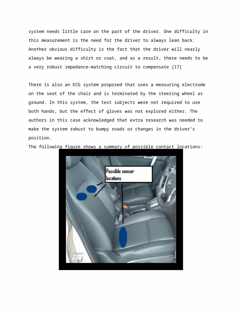
influence on the data and also needs to be accounted for. [21] Similar to the wheel sensor, two pieces of conductive fabric located at the backrest of the car seat could
take ECG measurements. Such a system needs little care on the part of the driver. One difficulty in this
measurement is the need for the driver to always lean back. Another obvious difficulty is the fact that the
driver will nearly always be wearing a shirt or coat, and as a result, there needs to be a very robust
impedance-matching circuit to compensate [17]
There is also an ECG system proposed that uses a measuring electrode on the seat of the chair and is
terminated by the steering wheel as ground. In this system, the test subjects were not required to use both
hands, but the effect of gloves was not explored either. The authors in this case acknowledged that extra
research was needed to make the system robust to bumpy roads or changes in the driver’s position.
The following figure shows a summary of possible contact locations:
Figure 5-15: Proposed ECG measurement locations
Alternatively, there have been other systems proposed, such as embedding a skin conductance sensor in
the user’s clothing[22], or placing extra electrodes on either the left or right armrest and/or the shift
lever[23]. The idea in such a case is to be able to measure the driver’s hand or arm in multiple different
locations.
Wristwatch:
As an alternative to having one sensor per car, a sensor can be situated on the driver. An example of this
technology is the Exmovere “Empath Watch”, which is designed to be worn 24 hours a day. This watch
takes multiple bio-signs:
Heart rate and heart rate variability
Skin temperature (and ambient temperature for comparison)
User acceleration
Skin conductance
Theoretically, the more bio-signs a sensor measures, the more accurate of a fatigue assessment it can
return. Using these signs, the device can detect a wide variety of user emotions and conditions, including
fatigue. The current design uses Bluetooth technology and can be used to send alerts via cell phone to
health providers, etc. Such a watch could easily be adapted to interface with any car the wearer drives, as
many cars do already have Bluetooth. Theoretically, the user would only need to press a button on the
watch when entering the car, which would allow the ease equivalent of “plug and play”. Also, since the
watch is always with one user, it could be made to adapt to the user’s unique bio-signs. In other words, it
could be ‘trained’ to work well with any specific user, which could give it an advantage over sensors
paired to any specific car. This is an emerging technology (currently in Version 1), however, and many
improvements need to be made on size, battery life, and durability. This device in its current state would
not be aesthetically acceptable to most users, as it is made of plastic and is much larger than conventional
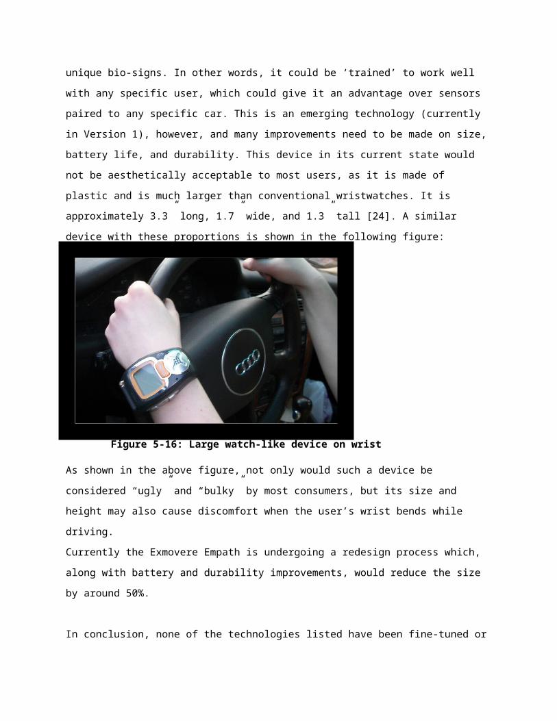
wristwatches. It is approximately 3.3” long, 1.7” wide, and 1.3” tall [24]. A similar device with these
proportions is shown in the following figure:
Figure 5-16: Large watch-like device on wrist
As shown in the above figure, not only would such a device be considered “ugly” and “bulky” by most
consumers, but its size and height may also cause discomfort when the user’s wrist bends while driving.
Currently the Exmovere Empath is undergoing a redesign process which, along with battery and
durability improvements, would reduce the size by around 50%.
In conclusion, none of the technologies listed have been fine-tuned or used in widespread use. All the
biometric detection systems listed are still in study, and there are currently no commercial available
systems of these types.
6 Behaviors Required for Accident Prevention
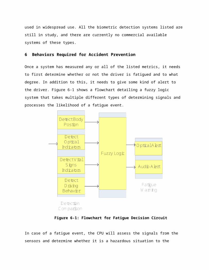
Once a system has measured any or all of the listed metrics, it needs to first determine whether or not the
driver is fatigued and to what degree. In addition to this, it needs to give some kind of alert to the driver.
Figure 6-1 shows a flowchart detailing a fuzzy logic system that takes multiple different types of
determining signals and processes the likelihood of a fatigue event.
Figure 6-1: Flowchart for Fatigue Decision Circuit
In case of a fatigue event, the CPU will assess the signals from the sensors and determine whether it is a
hazardous situation to the fatigued driver and his or her surroundings. The system will activate built-in
alerts gradually to wake up the driver, and not to startle him/her, which might cause more harm than help.
Most of the things that drivers do to fight off sleepiness while driving are not effective for more than 10
minutes. The alert system is useful to warn and provide drivers the opportunity to find safe place for rest.
Many proposed alert systems gradually increase the alert level and invasiveness, starting with the least
annoying or invasive actions, and growing more drastic if the user has persistent or worsening
drowsiness. For instance, the first warning indicators a vehicle could give include:
Issue flashing lights or signs such as “Wake up”, “Attention”, etc.
Issue warning tone or voice
Recommend a short nap via recorded voice or signs
Seat vibration
Additionally, the car could play a pre-recorded message to request that the driver speak so his voice could
be analyzed to confirm drowsiness, or attempt to engage the driver in some sort of voice conversation to
keep him mentally active. If the system detects repeated fatigue circumstances, stronger prevention
actions would be carried out to bring the driver to a safe condition. These actions require more
complicated electronic circuits and mechanical systems to be integrated into the automobile.
These would calculate and counteract the symptoms of the fatigued driving such as car swerving, lane
drifting, and speed change. For example, the vehicle may:
Apply brake to slow down and turn on the emergency flashers
Enforce a break period using preset starter-kill circuit
Dispatch for help if no response or improvement over a period of time
Figure 6- depicts a flow chart of corrective action and driver prevention in the event of
driver fatigue.

Figure 6-2: Flowchart for Corrective Action and Driver Prevention during Fatigued State
Visual (LED’s) and audio warning technologies have been widely implemented in the fatigue-detection
systems on the market. Auto-pilot for automobiles has been developed and tested by manufacturers and
other high-tech companies. When the technology becomes available (and possibly standard equipment for
future automobiles), it can be implemented in the fatigue-detection systems depending on the production
cost.
7 Current Commercial Technologies
There are very few driver fatigue products currently on the market. The most commonly used product in
the market is the Driver Nap Zapper. This product retails for about twenty five dollars and has been seen
on late night infomercials. The Driver Nap Zapper is nothing more than a head position sensor: when it
detects the position the head is tilted it gives off a high pitch audio alarm in the person’s ear. The device
is only effective if the person falls asleep with their head tilted forward and not backwards. The circuit is
nothing more than either an audio or vibration alert. The device fits over the ear similar to a hearing aid.
The optical products on the market are the Nap Alarm and the DD850 Driver Fatigue Monitor, which
operate and sell at roughly the same cost; five hundred United States Dollars (USD). Basically the device
monitors the person’s eyes to detect the blink rate. The device, upon detection, alarms the driver by either
blinking light and/or loud audio warning. This can create a distraction to the driver. In addition, only 80%
of the time will a person’s blink pattern be a key signal to their drowsiness.
A new product, the Empath Wristwatch, is the biometric detector closest to commercial use, and is
probably the most effective product in detecting driver fatigue as it attached directly to the user. The
product is somewhat bulky due to the integration of multiple sensors. The warning system is attached to
the watch so it could be ignored by the user unless the audio in the watch is strong enough to wake up the
driver unless it could be integrated into the car via Bluetooth. Preliminary costs show the product at over
one thousand USD and additional monthly service fee. Also, this product does not appear to be readily
available yet.
The final product is the Driver Assist Package featured on the Mercedes-Benz Class E class cars. These
cars Manufacturer’s Suggested Retail Price (MSRP) is listed at about $50,000 USD and the driver assist
feature is additional $3000 MSRP USD. The way this device work it stores the driver’s behavior. If it
notices the driver’s behavior to be erratic it will notify the driver to take a nap. Key parameters such as
the driver’s steering and braking behaviors are saved to analyze their reaction times. Table 7-1 shows a
product comparison, and even with the cost associated, the Driver Assist Package is the best product on
the market. Similar systems are available on some Cadillac, Lexus, BMW, Volvo, Audi, and Mercedes-
Benz cars.
According to Frost & Sullivan the consumer GPS market was 5.14 billion dollars in 2010. [25] This
market could generate 10-20% of the GPS market unless forced mandatory by the NHTSA where the

market could equal that of the consumer GPS market. At one time seat belts and air bags were optional
products. Mercedes is investing heavily in this market, showing the high car manufacturer sees a growth
potential.
Table 7-1: Current Driver Fatigue Products
Products
Pric
e Accurate
Non-
Invasive
Effectiv
e
Overall
Score Company
Detection
Type
Driver Nap Zapper 25 50% 3 3 5 No Nap Motion
Nap Alarm (LS888)500 80% 5 6 6
Leisure Auto
Security Optical
DD850 Driver
Fatigue Monitor 500 80% 5 6 6 Eye Alert Optical
Exmovere Empath
WristWatch 1000 90% 6 5 6 Exmovere Biometric
Driver Assist
Package 3000 90% 7 7 7 Mercedes Behavioral
8 Conclusion
As described throughout the paper, many technologies exist to detect driver fatigue. This paper tries to
look at the emerging technologies and determine the best approaches in trying to prevent the number one
cause of fatal vehicle crashes. Currently, the number one selling product in the market is the market is
nothing more than a reed switch to detect head angle tilt. This product is extremely limited and not very
effective. The product made by BMW and integrated into their high end cars to detect driver fatigue
behavior is slightly more effective is detection but lack proper notification to warn a driver. The current
market and technologies is in its infancy mode. New technologies keep emerging using different
techniques.
As the market emerges for driver fatigue devices and this problem is taken more serious by the public;
emergences of technologies and products is expected. The new technologies that will emerge will
possibly use a combination of sensors mentioned in the paper. The more sensors this new product can
incorporate the more likely the product will succeed. Research in understanding if the different sensors
are uncorrelated in how they detect fatigue can be critical increasing probability of detection. Using fuzzy
logic and maximum combining ratio techniques can be used to increased probability. Further expanding
this thought is how many sensors are required before diminishing returns are seen. Understanding the
probability of detection of each sensor is critical to determine which sensors should be used and which
ones should be ignored.
The next aspect of this technology is once there are positive signs of driver fatigue, what is the current
suggested path to alert the driver and place that person in a current safe state. As car technologies develop
collision avoidance, auto steering and driver assistance, what technologies and alert should be used. This
alone requires an entirely new set of research.
9 References
[1] “The 6 Most Common Causes of Automobile Crashes(2010)”. Retrieved February 9th 2011, from
http://www.sixwise.com/newsletters/05/07/20/the_6_most_common_causes_of_automobile_cras
hes.htm
[2] K. Strohl, J. Blatt, F. Council, K. Georges, J. Kiley, R. Kurrus, A. McCartt, S. Merritt, R.N, A.
Pack, S. Rogus, T. Roth, J. Stutts, P. Waller, and D. Willis, “Drowsy Driving and Automobile
Crashes” (2010), Retrieved February 21st 2011, from
http://www.nhtsa.gov/people/injury/drowsy_driving1/drowsy.html#NCSDR/NHTSA
[3] What causes Fatigue (2010), Retrieved February 21st 2011, from
http://unsafetrucks.org/driver_fatigue.htm
[4] H. Greeley, E. Friets,, J. Wilson, S. Raghavan and J. Berg, “Detecting Fatigue From Voice Using
Speech Recognition”, 2006 IEEE International Symposium on Signal Processing and Information
Technology
[5] D. Hu, G. Gong, C. Han, Z. Mu, and X. Zhao, “Modeling research on Driver Fatigue”, 2010
International Conference on Computer Application and System Modeling (ICCASM 2010)
[6]L. Bergasa, J. Nuevo, M. Sotelo, R. Barea, and M. Lopez, “Real-Time System for Monitoring
Driver Vigilance”, IEEE Transactions on Intelligent Transportation Systems, Vol. 7, no. 1, March
2006
[7] Z. Zhu, Q. Ji, K. Fujimura, and K. Lee, “Combining Kalman Filtering and Mean Shift for Real
Time Eye Tracking Under Active IR Illumination”, International Conference on Pattern
Recognition, Quebec, Canada, 2002
[8] US Department of Transportation, “An Evaluation of Emerging Driver Fatigue Detection
Measures and Technologies”, June 2009
[9] Haisong Gu, Qiang Ji, and Zhiwei Zhu, “Active Facial Tracking for Fatigue Detection” IEEE
Workshop on Applications of Computer Vision, Orlando, Florida, 2002.
[10]Y. Jie, Y. DaQuan, W. WeiNa, X. XiaoXia, and W. Hui, “Real-Time Detecting System of the
Driver’s Fatigue”, 2006
[11]L. Bergasa, J. Nuevo, M. Sotelo, R. Barea, and M. Lopez, “Real-Time System for Monitoring
Driver Vigilance”, IEEE Transactions on Intelligent Transportation Systems, vol. 7, no. 1, March,
2006
[12] S. Deshmukh, D. Radake, K. Hande , “Driver Fatigue Detection Using Sensor Network”,
International Journal of Engineering Science and Technology, NCICT Conference Special Issue,
pp 89-92, February 2011
[13] Y. Tanida, H. Hagiwara, “Simple Estimation of the Falling Asleep Period using the Lorenz Plot
for Heart Rate Interval”, JSMBE vol. 44, no. 1, pp. 156-162, Nov. 2005.
[14] S. Kar, M. Bhagat, and A. Routray, “EEG signal analysis for the assessment and quantification
of driver’s fatigue”, June 2010
[15] L. Servera, M. Fernandez-Chimeno, and M. González, “Study of Sleep Stages By Controlled
Inducement and Measurement of Drowsiness Related Biomedical Signals”, 4th International
IEEE EMBS Conference on Neural Engineering, April 2009
[16]P. Kithil, R. Jones, and J. MacCuish, “Development of Driver Alertness Detection System Using
Overhead Capacitive Sensor Array”, International Driving Symposium on Human Factors in
Driver Assessment, Training and Vehicle Design, Aspen, CO, 2001.
[17]X. Yu, “Real-time Nonintrusive Detection of Driver Drowsiness”, May 2009
[18] G. Yang, Y. Lin, and P. Bhattacharya , "A driver fatigue recognition model using fusion of
multiple features" Systems, Man and Cybernetics, 2005 IEEE International Conference on , vol.2,
no., pp. 1777- 1784 Vol. 2, 10-12 Oct. 2005
[19]The John Hopkins university Applied Physics Laboratory “Technologies: Drowsy Driver
Detection System” http://www.jhuapl.edu/ott/technologies/featuredtech/DDDS/
[20]T. Matsuda and M.Makikawa, “ ECG Monitoring of a Car Driver Using Capacitively-Coupled
Electrodes”, 30th Annual International IEEE EMBS Conference ,Vancouver, British Columbia,
Canada, August 2008
[21]Y. Lin, H. Leng, G. Yang, and H. Cai, “An intelligent noninvasive sensor for driver pulse wave
measurement,” IEEE Sensors J., vol. 7, no. 5, pp. 790–799, May 2007.
[22] M. Bundele, and R. Banerjee, “Design of Early Fatigue Detection Elements of a Wearable
Computing System for the Prevention of Road Accidents”, IEEE,International Society of
Automation, Vol 1 , pp 136-139, 2010
[23]I. Jeong, S. Jun, D. Lee and H. Yoon, “Development of Bio Signal Measurement System for
Vehicles”, 2007 International Conference on Convergence Information Technology
[24]Exmovere Holdings Inc, “The New Biotechnological Frontier: The Empath Watch”. Feb. 2011
http://www.exmovere.com/pdf/Exmovere_Wearable_Sensor_Research.pdf
[25] Frost & Sullivan’s, North American GPS Equipment Markets, 2010 (Report A601-22)
10 Acronyms
Acronym Definition
IED Improvised Explosive Devise
MSRP Manufacturer’s Suggested Retail Price
NHTSA National Highway Traffic Safety Administration
SPA Sense, Process & Act
USD United States Dollars