Embed Size (px)
Citation preview
Korea-Australia Rheology Journal September 2006 Vol. 18, No. 3 143
Korea-Australia Rheology JournalVol. 18, No. 3, September 2006 pp. 143-151
Numerical analysis of internal flow and mixing performance in
polymer extruder I: single screw element
Naksoo Kim*, Hongbum Kim and Jaewook Lee1
Dept. of Mechanical Engineering, Sogang University,1Dept. of Chemical and Biomolecular Engineering, Sogang University, 1, Sinsu-dong, Mapo-gu, Seoul 121-742, Korea
(Received June 6, 2006; final revision received August 28, 2006)
Abstract
We analyzed the non-Newtonian and non-isothermal flow in a single screw extruder system and inves-tigated the mixing performance with respect to the screw speed and the screw pitch. The viscosity of poly-mer melt was described with Carreau-Yasuda model. The mixing performance was computed numericallyby tracking the motions of particles in the screw element system. The extent of mixing was characterizedin terms of the deformation rate, the residence time distribution, and the strain. The results revealed that thehigh screw speed reduces the residence time but increases the deformation rate while the small screw pitchincreases the residence time. It is concluded that the high screw speed increases the dispersive mixing per-formance and the small screw pitch increases the distributive mixing performance.
Keywords : nano-composite, polymer extrusion process, single screw extruder, mixing performance, particle
tracking, residence time distribution
1. Introduction
As a screw extrusion process is a continuous and ther-
mally and mechanically uniform manufacturing method, it
is applied for production of high molecular material to fab-
ricate nano-composites. Excellent design of screw extruder
and optimization of process conditions may enhance the
efficiency of mixing performance of nano-scaled clay par-
ticles in polymer matrix. Despite the importance of design
and analysis of polymer extrusion processes to manufac-
ture nano-composites with uniformly distributed clay par-
ticles, the lack of researches on the screw extruders makes
industry to design and to operate the process based on the
experience rather than on the systematic knowledge. It is
imperative that we analyze the flow characteristics of poly-
mer melt in a screw extruder with proper numerical meth-
ods and obtain the data to be utilized in the actual
processes.
Most numerical analyses on the screw extrusion process
have been done with simplified geometries and with many
assumptions due to the difficulties lying in modeling of
complicated shape of screw extruders. Though we may
grasp and investigate the basic tendencies about the poly-
mer flow through modeling with approximate geometries
and with many assumptions, it is not easy for us to under-
stand the detailed flow characteristics of polymer melt in a
screw extruder.
Griffith (1962) analyzed the fully developed flow of
incompressible fluid in a single screw extruder with an
assumption that the velocity and the temperature profiles
are equal in infinite plane using power-law viscosity
model. Fenner (1977) analyzed the flow in a screw
extruder and the temperature development along the screw
channel. Karwe and Jaluria (1990) solved thermal transfer
of a non-Newtonian fluid with assumptions that the tem-
perature distribution is known and adiabatic conditions are
applied onto the screw surface. Sastrohartono et al. (1994)
analyzed the flow in a screw extruder by using the march-
ing scheme to describe the circulation flow in channel and
then verified the results with experiments. Raman et al.
(1996) extended the previous research and successfully
analyzed the reverse flow due to back pressure. Kim and
Kwon solved the three dimensional velocity fields in a sin-
gle screw extruder using the finite element method and
proposed the screw design to enhance the mixing perfor-
mance. (Kim and Kwon, 1996a, 1996b)
Ghoreishy and Nouri (1999) carried out a numerical
analysis of the high molecular fluid flow using the finite
element method in the metering section and the die. They
verified the numerical results with experiments. Syrjala
(1999) carried out a research on the three dimensional fluid
flow in the conveying section of single screw extruder
using the marching scheme which contiguously solved the
equation given in the perpendicular section to down chan-
nel. The validity of the methodology has been verified later*Corresponding author: [email protected]© 2006 by The Korean Society of Rheology
Naksoo Kim, Hongbum Kim and Jaewook Lee
144 Korea-Australia Rheology Journal
with experiment data (Syrjala, 2000). Kwag et al. (2001)
performed researches on the three dimensional flow and
the thermal analysis of non-Newtonian fluid in a single
screw extruder using a commercial code, STAR-CD, based
on the finite volume method. They overcame the limit of
marching scheme (Syrjala, 1999; 2000) in analyzing the
reverse flow due to back pressure.
Previous researches have the limit of accuracy because of
using simplified models of screw extruders. Ahmad and
Jean-Robert (2005) modeled a screw extruder without
geometry approximation and carried out a three dimen-
sional numerical analysis for the non-isothermal steady-
state flows using the finite volume method. Ye et al. (2005)
carried out a research about polymer extrusion processes
with the finite element method using a 4-step fractional
method.
So far, most researches have analyzed the polymer flow
in single screw extruders with simplified modeling or
assumption of contiguous quasi-steady states because of
difficulty in describing analysis domain of screw extruder
with dynamic boundary conditions. Assumption of quasi-
steady states may yield to significant errors, because of that
the convection effect is bigger than that of conduction in
calculating the temperature filed. Especially, the error
resulted from the assumption of quasi-steady states
increases as the screw speed becomes fast enough that the
influence of convection increases. The flow in a screw
extruder is non-steady state since the flow channel varies
with time due to the rotation of the screw element in a bar-
rel. As the flow in a screw extruder is a dynamic boundary
problem, we may improve the accuracy of numerical
results by regarding the problem as a 3-D, non-steady state,
and non-isothermal flow.
In this study, we modeled and analyzed sectional screw
elements as detailed as possible to investigate the flow
field and to understand the effect of processing parameters.
Preliminary numerical results showed that the mixing per-
formance varied with processing parameters and geome-
tries. The final goal of this study is to establish a proper
method of numerical analysis for screw extrusion pro-
cesses.
2. Geometry and process parameters
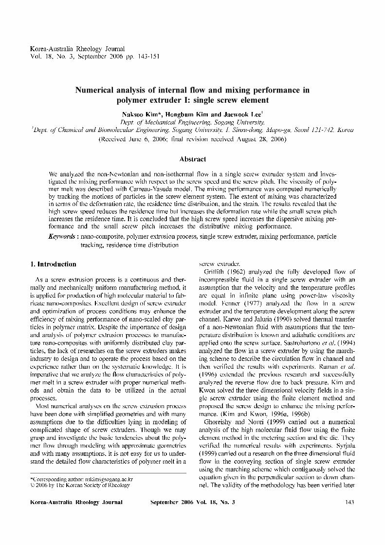
2.1. Shape of screw extruderA single screw extruder is modeled as shown in Fig. 1 to
calculate the mixing performance with respect to the screw
speed as a process parameter and the screw pitch length as
a geometry parameter. The geometry of the screw element
has been chosen as simple as possible to avoid manufac-
turing difficulties in the future experimental verification.
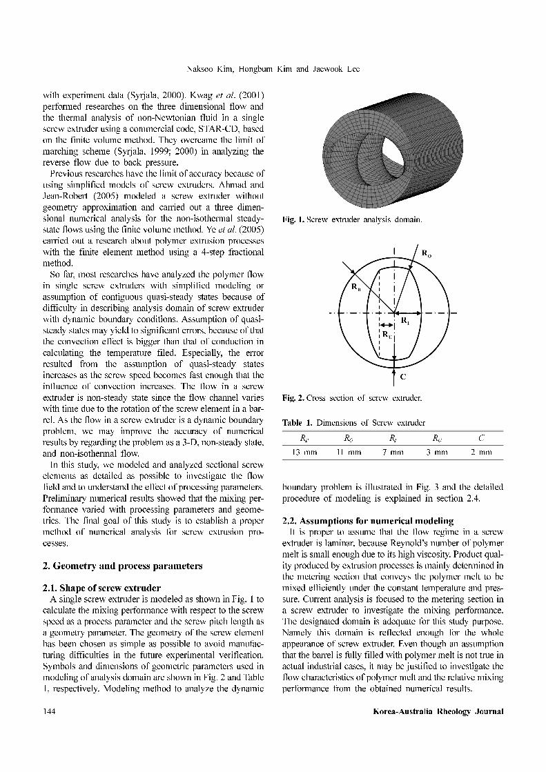
Symbols and dimensions of geometric parameters used in
modeling of analysis domain are shown in Fig. 2 and Table
1, respectively. Modeling method to analyze the dynamic
boundary problem is illustrated in Fig. 3 and the detailed
procedure of modeling is explained in section 2.4.
2.2. Assumptions for numerical modelingIt is proper to assume that the flow regime in a screw
extruder is laminar, because Reynold’s number of polymer
melt is small enough due to its high viscosity. Product qual-
ity produced by extrusion processes is mainly determined in
the metering section that conveys the polymer melt to be
mixed efficiently under the constant temperature and pres-
sure. Current analysis is focused to the metering section in
a screw extruder to investigate the mixing performance.
The designated domain is adequate for this study purpose.
Namely this domain is reflected enough for the whole
appearance of screw extruder. Even though an assumption
that the barrel is fully filled with polymer melt is not true in
actual industrial cases, it may be justified to investigate the
flow characteristics of polymer melt and the relative mixing
performance from the obtained numerical results.
Fig. 1. Screw extruder analysis domain.
Fig. 2. Cross section of screw extruder.
Table 1. Dimensions of Screw extruder
RB RO RI RU C
13 mm 11 mm 7 mm 3 mm 2 mm
Numerical analysis of internal flow and mixing performance in polymer extruder I: single screw element
Korea-Australia Rheology Journal September 2006 Vol. 18, No. 3 145
Assumptions used for the flow analysis of screw extruder
are summarized as follows:
(1) The flow regime in screw extruder is laminar.
(2) The polymer melt is an incompressible fluid.
(3) The viscosity is modeled to a function of temperature
and shear rate.
(4) Heat is generated due to the viscous dissipation of
polymer melt.
(5) Thermal condition between the screw surface and the
polymer melt is adiabatic.
(6) The no-slip condition is imposed onto the solid
boundary.
(7) Density and specific heat are constant.
(8) The barrel is fully filled with polymer melt.
(9) The steady state flow of polymer melt is attained
after the screw rotates enough revolutions. During
each time step, the screw rotates by a given angle.
2.3. Boundary conditionsBased on the assumptions described in the previous sec-
tion, the following boundary conditions to the flow prob-
lem in a screw extruder have been imposed:
(1) No-slip boundary condition is imposed on the solid
surfaces of screw and barrel. In other words, the rel-
ative velocity of polymer melt faced with solid in
each direction is zero.
(2) Barrel temperature is uniform overall as 200oC.
(3) Initial temperature of polymer melt at inlet is con-
stant to 190oC and the temperature boundary con-
dition at outlet is dT/dz = 0.
(4) Pressures at inlet and outlet are set to be zero.
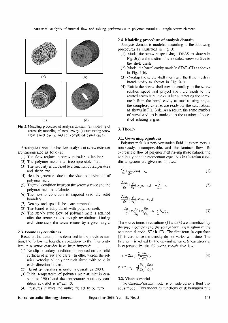
2.4. Modeling procedure of analysis domainAnalysis domain is modeled according to the following
procedures as illustrated in Fig. 3:
(1) Model the screw shape using I-DEAS as shown in
Fig. 3(a) and transform the modeled screw surface to
the shell mesh.
(2) Model the barrel cavity mesh in STAR-CD as shown
in Fig. 3(b).
(3) Overlap the screw shell mesh and the fluid mesh in
barrel cavity as shown in Fig. 3(c).
(4) Rotate the screw shell mesh according to the screw
rotation speed and project the fluid mesh to the
rotated screw shell mesh. After subtracting the screw
mesh from the barrel cavity at each rotating angle,
the completed cavities are ready for the calculation,
as shown in Fig. 3(d). As a result, the same number
of barrel cavities is modeled as the number of spec-
ified rotating angles.
3. Theory
3.1. Governing equationsPolymer melt is a non-Newtonian fluid. It experiences a
non-steady, incompressible, and the laminar flow. To
express the flow of polymer melt having these natures, the
continuity and the momentum equations in Cartesian coor-
dinate system are given as follows:
(1)
(2)
(3)
The source terms in equations (1) and (3) are discretized by
the piso algorithm and the source term linearization in the
commercial code, STAR-CD. The first term in equations
(1) is zero since the density do not varies with time. The
flux term is solved by the upwind scheme. Shear stress τijis expressed by the following constitutive law.
(4)
where
3.2. Viscous modelThe Carreau-Yasuda model is considered as a fluid vis-
cous model. This model as functions of deformation rate
∂ρ∂t------ ∂
∂xi
------ ρui( )+ sm=
∂ρui
∂t---------- ∂
∂xi
------ ρujui τij+( )+∂p
∂xi
------– si+=
∂ρht
∂t---------- ∂
∂xi
------ ρhiuj Fh j,+( )+
∂p
∂t------ uj
∂p
∂xj
------ τij
∂ui
∂xj
------- sh Hmsc m,m∑–+ + +=
τij 2µsij2
3---µ
∂uk
∂xk
-------δij,–=
sij1
2---
∂ui
∂xj
-------∂uj
∂xi
-------+⎝ ⎠⎛ ⎞.=
Fig. 3. Modeling procedure of analysis domain; (a) modeling of
screw, (b) modeling of barrel cavity, (c) subtracting screw
from barrel cavity, and (d) completed barrel cavity.
Naksoo Kim, Hongbum Kim and Jaewook Lee
146 Korea-Australia Rheology Journal
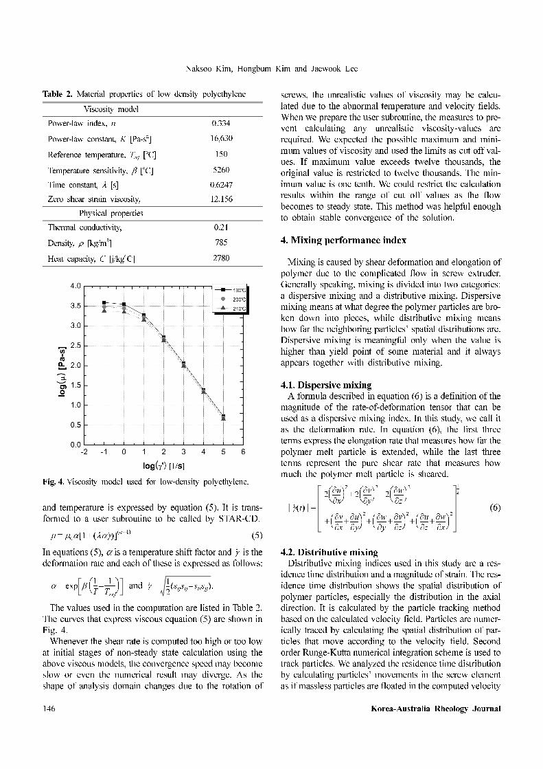
and temperature is expressed by equation (5). It is trans-
formed to a user subroutine to be called by STAR-CD.
(5)
In equations (5), α is a temperature shift factor and is the
deformation rate and each of these is expressed as follows:
and
The values used in the computation are listed in Table 2.
The curves that express viscous equation (5) are shown in
Fig. 4.
Whenever the shear rate is computed too high or too low
at initial stages of non-steady state calculation using the
above viscous models, the convergence speed may become
slow or even the numerical result may diverge. As the
shape of analysis domain changes due to the rotation of
screws, the unrealistic values of viscosity may be calcu-
lated due to the abnormal temperature and velocity fields.
When we prepare the user subroutine, the measures to pre-
vent calculating any unrealistic viscosity-values are
required. We expected the possible maximum and mini-
mum values of viscosity and used the limits as cut off val-
ues. If maximum value exceeds twelve thousands, the
original value is restricted to twelve thousands. The min-
imum value is one tenth. We could restrict the calculation
results within the range of cut off values as the flow
becomes to steady state. This method was helpful enough
to obtain stable convergence of the solution.
4. Mixing performance index
Mixing is caused by shear deformation and elongation of
polymer due to the complicated flow in screw extruder.
Generally speaking, mixing is divided into two categories:
a dispersive mixing and a distributive mixing. Dispersive
mixing means at what degree the polymer particles are bro-
ken down into pieces, while distributive mixing means
how far the neighboring particles’ spatial distributions are.
Dispersive mixing is meaningful only when the value is
higher than yield point of some material and it always
appears together with distributive mixing.
4.1. Dispersive mixingA formula described in equation (6) is a definition of the
magnitude of the rate-of-deformation tensor that can be
used as a dispersive mixing index. In this study, we call it
as the deformation rate. In equation (6), the first three
terms express the elongation rate that measures how far the
polymer melt particle is extended, while the last three
terms represent the pure shear rate that measures how
much the polymer melt particle is sheared.
(6)
4.2. Distributive mixingDistributive mixing indices used in this study are a res-
idence time distribution and a magnitude of strain. The res-
idence time distribution shows the spatial distribution of
polymer particles, especially the distribution in the axial
direction. It is calculated by the particle tracking method
based on the calculated velocity field. Particles are numer-
ically traced by calculating the spatial distribution of par-
ticles that move according to the velocity field. Second
order Runge-Kutta numerical integration scheme is used to
track particles. We analyzed the residence time distribution
by calculating particles’ movements in the screw element
as if massless particles are floated in the computed velocity
µ µ0α 1 λαγ·( )+[ ] n 1–( )
=
γ·
α exp β 1
T---
1
Tref
-------–⎝ ⎠⎛ ⎞= γ·
1
2--- sijsij siisjj–( ).=
γ· t( )
2∂u
∂x------⎝ ⎠
⎛ ⎞2
2∂v
∂y-----⎝ ⎠
⎛ ⎞2
2∂w
∂z-------⎝ ⎠
⎛ ⎞2
+ +
∂v
∂x-----
∂u
∂y------+⎝ ⎠
⎛ ⎞2 ∂w
∂y-------
∂v
∂z-----+⎝ ⎠
⎛ ⎞2 ∂u
∂z------
∂w
∂x-------+⎝ ⎠
⎛ ⎞2
+ + +
1
2---
=
Table 2. Material properties of low density polyethylene
Viscosity model
Power-law index, n 0.334
Power-law constant, K [Pa-sn] 16,630
Reference temperature, Tref [oC] 150
Temperature sensitivity, β [oC] 5260
Time constant, λ [s] 0.6247
Zero shear strain viscosity, 12,156
Physical properties
Thermal conductivity, 0.21
Density, ρ [kg/m3] 785
Heat capacity, C [j/kgoC] 2780
Fig. 4. Viscosity model used for low-density polyethylene.
Numerical analysis of internal flow and mixing performance in polymer extruder I: single screw element
Korea-Australia Rheology Journal September 2006 Vol. 18, No. 3 147
field. To prevent the loss of particles due to flowing back-
ward, all particles distribute evenly among all in front of
the inlet cross section. The residence time distribution is
indicated as a cumulated ratio of all tracking particles to
particles that arrive at outlet. The value is expressed as a
cumulative distribution function.
F(t) = Cout(t)/C∞, (7)
where Cout(t) is the number of particles that arrive in outlet
according to time and C∞ is total number of tracking par-
ticles. Function F(t) becomes zero when time t is zero and
it becomes unity when time t approaches to infinite, while
the slope of function cannot become negative. Another
index of distributive mixing is a strain that is expressed in
equation (8).
(8)
The difference between the two indices is that the res-
idence time distribution shows the characteristics of mac-
roscopic mixing or bulk flow, while the strain shows the
degree of microscopic mixing. That is to say, the residence
time distribution represents a qualitative measure of dis-
tributive mixing, while the strain gives a quantitative one.
5. Results and discussion
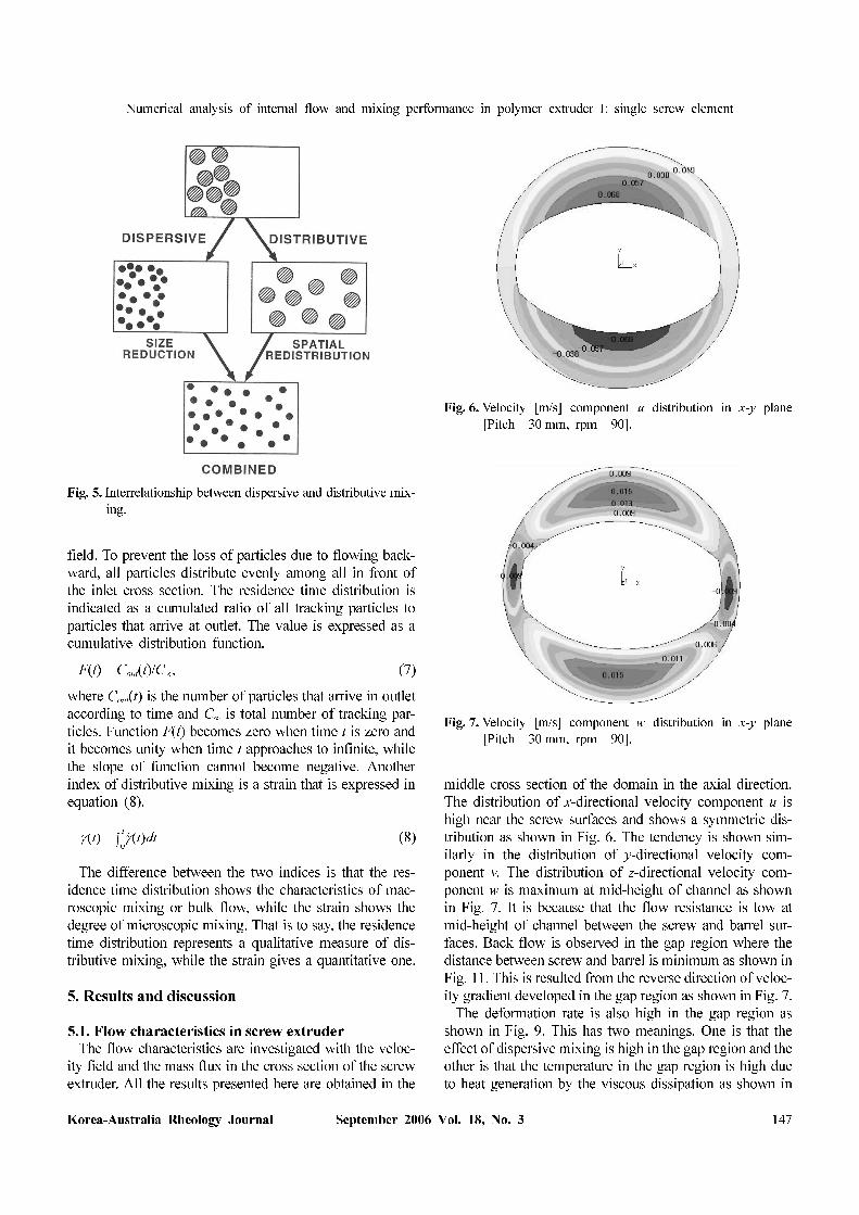
5.1. Flow characteristics in screw extruderThe flow characteristics are investigated with the veloc-
ity field and the mass flux in the cross section of the screw
extruder. All the results presented here are obtained in the
middle cross section of the domain in the axial direction.
The distribution of x-directional velocity component u is
high near the screw surfaces and shows a symmetric dis-
tribution as shown in Fig. 6. The tendency is shown sim-
ilarly in the distribution of y-directional velocity com-
ponent v. The distribution of z-directional velocity com-
ponent w is maximum at mid-height of channel as shown
in Fig. 7. It is because that the flow resistance is low at
mid-height of channel between the screw and barrel sur-
faces. Back flow is observed in the gap region where the
distance between screw and barrel is minimum as shown in
Fig. 11. This is resulted from the reverse direction of veloc-
ity gradient developed in the gap region as shown in Fig. 7.
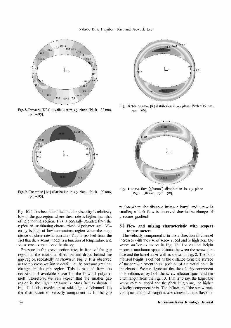
The deformation rate is also high in the gap region as
shown in Fig. 9. This has two meanings. One is that the
effect of dispersive mixing is high in the gap region and the
other is that the temperature in the gap region is high due
to heat generation by the viscous dissipation as shown in
γ t( ) γ· t( )dt0
t
∫=
Fig. 5. Interrelationship between dispersive and distributive mix-
ing.
Fig. 6. Velocity [m/s] component u distribution in x-y plane
[Pitch = 30 mm, rpm = 90].
Fig. 7. Velocity [m/s] component w distribution in x-y plane
[Pitch = 30 mm, rpm = 90].
Naksoo Kim, Hongbum Kim and Jaewook Lee
148 Korea-Australia Rheology Journal
Fig. 10. It has been identified that the viscosity is relatively
low in the gap region where shear rate is higher than that
of neighboring section. This is generally resulted from the
typical shear thinning characteristic of polymer melt. Vis-
cosity is high at low temperature region when the mag-
nitude of shear rate is constant. This is resulted from the
fact that the viscous model is a function of temperature and
shear rate as mentioned in theory.
Pressure in the cross section rises in front of the gap
region in the rotational direction and drops behind the
gap region repeatedly as shown in Fig. 8. It is observed
at the x-y cross section in detail that the pressure gradient
changes in the gap region. This is resulted from the
reduction of available space for the flow of polymer
melt. Therefore, we can expect that the smaller gap
region is, the higher pressure is. Mass flux as shown in
Fig. 11 is also maximum at mid-height of channel like
the distribution of velocity component w. In the gap
region where the distance between barrel and screw is
smaller, a back flow is observed due to the change of
pressure gradient.
5.2. Flow and mixing characteristic with respect
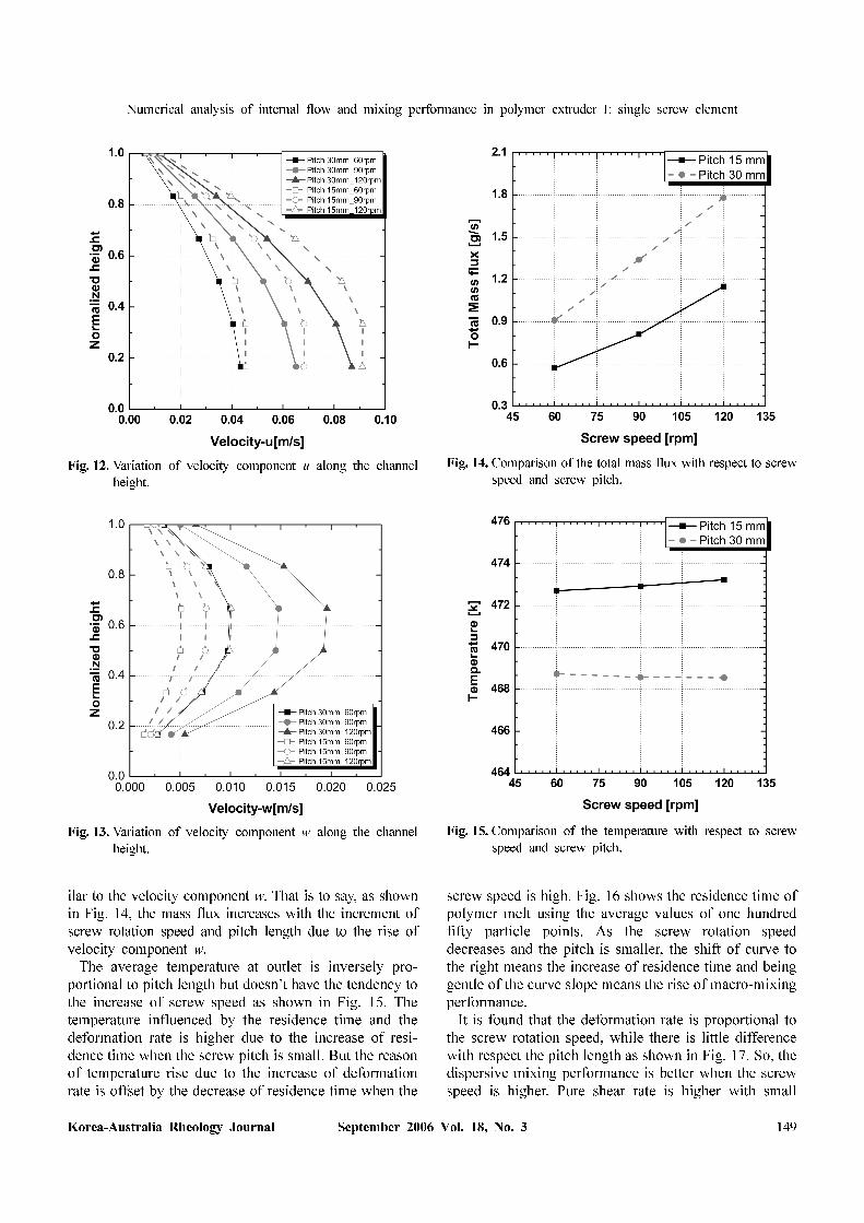
to parametersThe velocity component u in the x-direction in channel
increases with the rise of screw speed and is high near the
screw surface as shown in Fig. 12. The channel height
means a maximum space distance between the screw sur-
face and the barrel inner wall as shown in Fig. 2. The nor-
malized height is defined as the distance from the surface
of the screw element to the position of a material point in
the channel. We can figure out that the velocity component
w is influenced by both the screw rotation speed and the
pitch length from the Fig. 13. That is to say, the larger the
screw rotation speed and the pitch length are, the higher
velocity component w is. The influence of the screw rota-
tion speed and pitch length is also shown at mass flux sim-
Fig. 8. Pressure [KPa] distribution in x-y plane [Pitch = 30 mm,
rpm = 90].
Fig. 9. Shear-rate [1/s] distribution in x-y plane [Pitch = 30 mm,
rpm = 90].
Fig. 10. Temperature [K] distribution in x-y plane [Pitch = 15 mm,
rpm = 90].
Fig. 11. Mass flux [g/s/mm2] distribution in x-y plane
[Pitch = 30 mm, rpm = 90].
Numerical analysis of internal flow and mixing performance in polymer extruder I: single screw element
Korea-Australia Rheology Journal September 2006 Vol. 18, No. 3 149
ilar to the velocity component w. That is to say, as shown
in Fig. 14, the mass flux increases with the increment of
screw rotation speed and pitch length due to the rise of
velocity component w.
The average temperature at outlet is inversely pro-
portional to pitch length but doesn’t have the tendency to
the increase of screw speed as shown in Fig. 15. The
temperature influenced by the residence time and the
deformation rate is higher due to the increase of resi-
dence time when the screw pitch is small. But the reason
of temperature rise due to the increase of deformation
rate is offset by the decrease of residence time when the
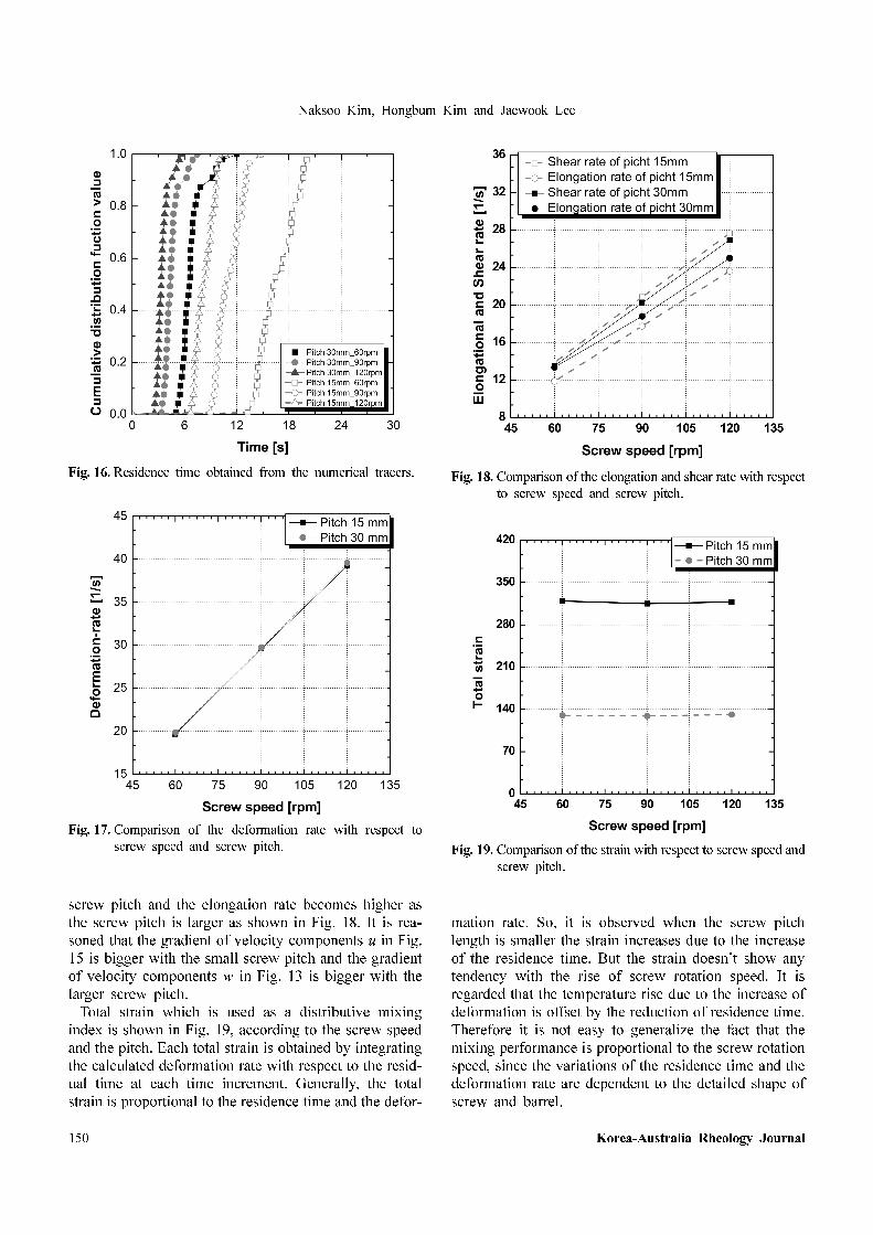
screw speed is high. Fig. 16 shows the residence time of
polymer melt using the average values of one hundred
fifty particle points. As the screw rotation speed
decreases and the pitch is smaller, the shift of curve to
the right means the increase of residence time and being
gentle of the curve slope means the rise of macro-mixing
performance.
It is found that the deformation rate is proportional to
the screw rotation speed, while there is little difference
with respect the pitch length as shown in Fig. 17. So, the
dispersive mixing performance is better when the screw
speed is higher. Pure shear rate is higher with small
Fig. 12. Variation of velocity component u along the channel
height.
Fig. 13. Variation of velocity component w along the channel
height.
Fig. 14. Comparison of the total mass flux with respect to screw
speed and screw pitch.
Fig. 15. Comparison of the temperature with respect to screw
speed and screw pitch.
Naksoo Kim, Hongbum Kim and Jaewook Lee
150 Korea-Australia Rheology Journal
screw pitch and the elongation rate becomes higher as
the screw pitch is larger as shown in Fig. 18. It is rea-
soned that the gradient of velocity components u in Fig.
15 is bigger with the small screw pitch and the gradient
of velocity components w in Fig. 13 is bigger with the
larger screw pitch.
Total strain which is used as a distributive mixing
index is shown in Fig. 19, according to the screw speed
and the pitch. Each total strain is obtained by integrating
the calculated deformation rate with respect to the resid-
ual time at each time increment. Generally, the total
strain is proportional to the residence time and the defor-
mation rate. So, it is observed when the screw pitch
length is smaller the strain increases due to the increase
of the residence time. But the strain doesn’t show any
tendency with the rise of screw rotation speed. It is
regarded that the temperature rise due to the increase of
deformation is offset by the reduction of residence time.
Therefore it is not easy to generalize the fact that the
mixing performance is proportional to the screw rotation
speed, since the variations of the residence time and the
deformation rate are dependent to the detailed shape of
screw and barrel.
Fig. 16. Residence time obtained from the numerical tracers.
Fig. 17. Comparison of the deformation rate with respect to
screw speed and screw pitch.
Fig. 18. Comparison of the elongation and shear rate with respect
to screw speed and screw pitch.
Fig. 19. Comparison of the strain with respect to screw speed and
screw pitch.
Numerical analysis of internal flow and mixing performance in polymer extruder I: single screw element
Korea-Australia Rheology Journal September 2006 Vol. 18, No. 3 151
6. Conclusions
We calculated the velocity field around the metering sec-
tion of screw element with varying the screw rotation
speed that is an operation condition and the pitch length
that is a shape parameter, with a commercial code, STAR-
CD. The mixing performances are also analyzed in detail
according to the parameters. The followings are concluded
based on the computation results:
1. The velocity components u, v are high near the screw
surface and the velocity component w is maximum at
mid-height of channel.
2. The pressure is high in the gap region because avail-
able space for flow is small.
3. The high deformation rate in the gap region results in
low viscosity together with high temperature due to
much viscous dissipation.
4. As the screw rotation speed increases, both the mass
flux and the deformation rate become higher, resulting
in the better dispersive mixing performance.
5. As the screw length become small, the conveying
capacity decreases, while the distributive mixing per-
formance is better due to the increase of residence
time of polymer melt.
Nomenclatures
Fh, j : diffusion energy flux in the xj-direction
ht : thermal enthalpy
n : power-law index
p : pressure
si : momentum source term
sm : mass source term
sc, m : rate of production or consumption of species m
due to reaction
sh : energy source term
Tref : reference temperature
ui : velocity components in the xi-direction
u, v, w : velocity components in the x-, y-, z-directions
respectively
Greek Letters
τij : stress tensor components
ρ : mass density
δij : Kronecker’s delta
α : temperature shift factor
: deformation rate
µ : viscosity
β : temperature sensitivity of µ
λ : a time constant
µ0 : zero shear viscosity
Acknowledgements
This work was supported by Korean Research Founda-
tion Grant (KRF-2004-005-D00001).
References
Ahmad, K. and C. Jean-Robert, 2005, Numerical simulation of
non-isothermal three-dimensional flows in an extruder by a
finite volume method, J. non-Newtonian Fluid Mech. 126, 7.
Fenner, R.T., 1977, Development in the analysis of steady screw
extrusion of polymers, Polymer 18, 617.
Ghoreishy, M. and M.R. Nouri, 1999, Finite element analysis of
thermoplastic melts flow through the metering and die regions
of single screw extruder, Inc. J. Appl. Polymer Sci. 74, 676.
Griffith, R.M., 1962, Fully developed flow in screw extruder,
Ind. Eng. Chem. Fundamentals 1, 180.
Karwe, M.V. and T. Jaluria, 1990, Numerical simulation of fluid
flow and heat transfer in single screw extruder for non-New-
tonian fluids, Numerical, Part A 17, 167.
Kim, S.J. and T.H. Kwon, 1996a, Enhancement of mixing per-
formance of single-screw extrusion processes via chaotic
flows: Part 1, Basic concepts and experimental study,
Advances in Ploymer Tech. 15, 41.
Kim, S.J. and T.H. Kwon, 1996b, Enhancement of mixing per-
formance of single-screw extrusion processes via chaotic
flows: Part 1, Basic concepts and experimental study,
Advances in Ploymer Tech. 15, 41.
Kwag, D.S., W.S. Kim, K.S. Lee and M.Y. Lyu, 2001, A three-
dimensional numerical study of fluid flow and heat transfer in
the single screw extruder, Proceeding of the second Inter-
national Conference on Computational Heat and Mass Trans-
fer, 22-26.
Raman, V., Y. Chiruvella, Y. Jaluria and V. Sernas, 1996, Extru-
sion of non-newtonian fluid in a single-screw extruder with
pressure back flow, Polymer Eng. and Sci. 36, 358.
Sastrohartono, T., Y. Jaluria, M. Esseghir and V. Sernas, 1994, A
numerical and experimental study of three-dimensional trans-
port in the channel of an extruder for polymeric materials, Int.
J. Heat Mass Transfer 38, 1957.
Syrjala, S., 1999, On the analysis of fluid flow and heat transfer
in the melt conveying section of a single screw extruder,
Numerical Heat Transfer, Part A 35, 25.
Syrjala, S., 2000, Numerical simulation of non-isothermal flow
of polymer melt in a single screw extruder: A validation study,
Numerical Heat Transfer, Part A 37, 897.
Ye, Y.S., H.B. Kim, N. Kim and J.W. Lee, 2005, A study on anal-
ysis of polymer extruder process using the finite element
method, The Korean Society of Mechanical Engineers Part A
29, 145.
γ·