Embed Size (px)
Citation preview
page 1
Image Enhancement and Understanding for Remote Visual Inspection of Aircraft Surface.
Priyan Gunatilake*, M.W. Siegel** , A.J. Jordan*,** , G. Podnar**
*Department of Electrical and Computer Engineering** Robotics Institute, School of Computer Science
Carnegie Mellon UniversityPittsburgh, PA.
ABSTRACTWe describe a library of image enhancement and understanding algorithms developed to enhanceand recognize surface defects from remote live imagery of an aircraft surface. Also described arethe supporting mobile robot platform that generates the remote stereoscopic imagery and theinspection console containing a graphical user interface, through which the inspector accessesthe live imagery for remote inspection. We will discuss initial results of the remote imaging pro-cess and the image processing library, and speculate on their future application in aircraft inspec-tion.
Keywords: ANDI, CIMP, aircraft visual inspection, remote visual inspection, image enhancement, imageunderstanding, stereo vision
1. Introduction
Visual inspection is, by far, the most widely used method in aircraft surface inspection.1 However, the current
practice of getting on the aircraft body to carry out inspection raises safety issues for the inspector, is time con-
suming, and suffers at times from being ineffective due to inspector fatigue or boredom.2 Enhanced remote
visual inspection could allow the inspector to safely, quickly and accurately perform the necessary visual
inspection. We are currently developing a prototype aircraft-capable mobile robot called the Crown Inspection
Mobile Platform (CIMP). CIMP relays high quality, live stereoscopic imagery of the aircraft crown to an
inspection console manned by the inspector. The inspector, with the aid of computer enhancement and intelli-
gence, examines the imagery for surface defects.
In this paper, we will describe several image enhancement algorithms, and an inspector's interface for access-
ing them, for highlighting surface cracks, scratches, lightning strikes and corrosion in the live imagery. Image
enhancement algorithms emphasizes image features that are characteristic of surface defects such as cracks
and corrosion. We will also describe some experiments with an image understanding algorithm that use 2D and
3D features extracted from live imagery combined with an active vision sensor developed in our laboratory.
Image understanding algorithms may, in the foreseeable future, make it feasible to automate screening of large
volumes of image data so that inspectors can concentrate on imagery suggestive of anomalies; in the more dis-
tant future, ongoing progress may permit an even greater degree of machine assistance and automation for
visual detection of surface cracks and corrosion.
Image enhancement and understanding algorithms are already extensively used with great success in medical
imaging applications, and we believe that they could make a similar impact in the area of aircraft surface
page 2
inspection.
1.1 Background
TheAutomatedNon-DestructiveInspection (ANDI) robot, developed at Carnegie Mellon University, success-
fully demonstrated mobility, manipulation and navigational capabilities of a robot on an aircraft surface.3,4
ANDI carried a sensor package consisting of an eddy current probe and four cameras for remote navigation.
The cameras were useful for observing gross visual features, but not of optical or electronic quality suitable for
detailed visual inspection. However, due to the emphasis on mobility and navigation, the issue of accumulating
useful inspection data was not addressed at length. After the initial demonstration of ANDI, the second author
launched another research effort with the twin objectives of designing a sensor package for CIMP that would
generate useful inspection data, and developing a graphical user interface (GUI) and a library of image
enhancement and understanding algorithms, through which an inspector could access, enhance and recognize
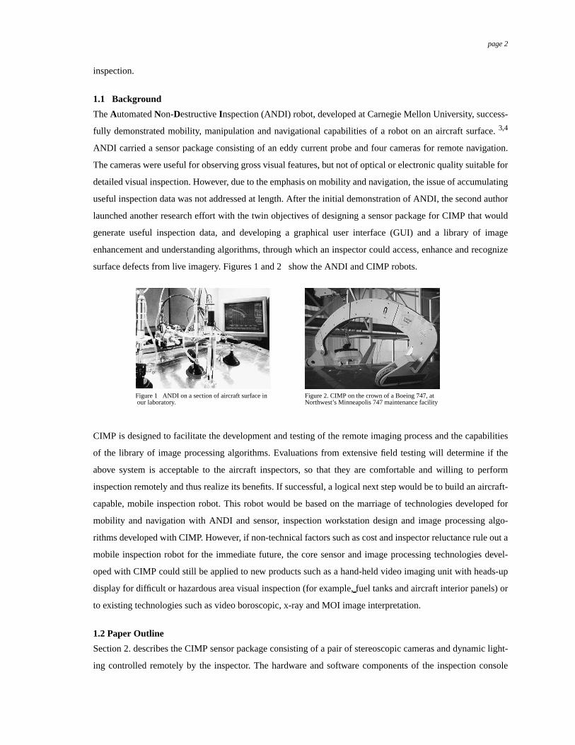
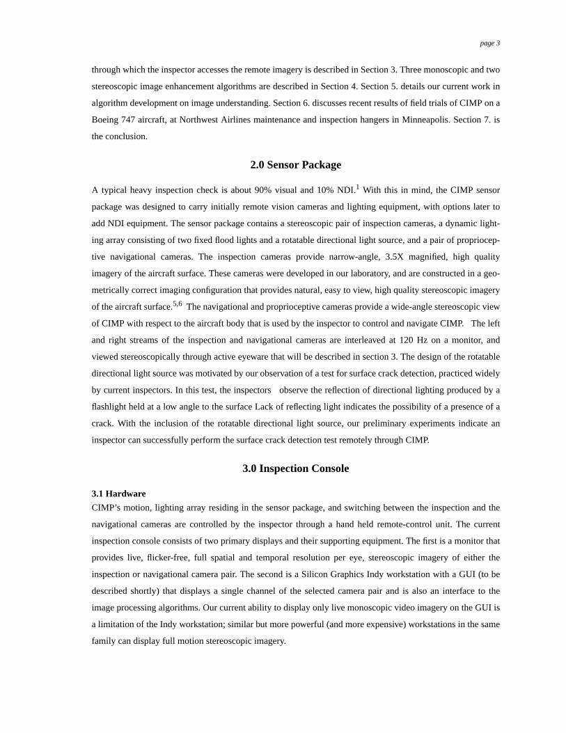
surface defects from live imagery. Figures 1 and 2 show the ANDI and CIMP robots.
CIMP is designed to facilitate the development and testing of the remote imaging process and the capabilities
of the library of image processing algorithms. Evaluations from extensive field testing will determine if the
above system is acceptable to the aircraft inspectors, so that they are comfortable and willing to perform
inspection remotely and thus realize its benefits. If successful, a logical next step would be to build an aircraft-
capable, mobile inspection robot. This robot would be based on the marriage of technologies developed for
mobility and navigation with ANDI and sensor, inspection workstation design and image processing algo-
rithms developed with CIMP. However, if non-technical factors such as cost and inspector reluctance rule out a
mobile inspection robot for the immediate future, the core sensor and image processing technologies devel-
oped with CIMP could still be applied to new products such as a hand-held video imaging unit with heads-up
display for difficult or hazardous area visual inspection (for example,fuel tanks and aircraft interior panels) or
to existing technologies such as video boroscopic, x-ray and MOI image interpretation.
1.2 Paper Outline
Section 2. describes the CIMP sensor package consisting of a pair of stereoscopic cameras and dynamic light-
ing controlled remotely by the inspector. The hardware and software components of the inspection console
Figure 1 ANDI on a section of aircraft surface in our laboratory.
Figure 2. CIMP on the crown of a Boeing 747, atNorthwest’s Minneapolis 747 maintenance facility
page 3
through which the inspector accesses the remote imagery is described in Section 3. Three monoscopic and two
stereoscopic image enhancement algorithms are described in Section 4. Section 5. details our current work in
algorithm development on image understanding. Section 6. discusses recent results of field trials of CIMP on a
Boeing 747 aircraft, at Northwest Airlines maintenance and inspection hangers in Minneapolis. Section 7. is
the conclusion.
2.0 Sensor Package
A typical heavy inspection check is about 90% visual and 10% NDI.1 With this in mind, the CIMP sensor
package was designed to carry initially remote vision cameras and lighting equipment, with options later to
add NDI equipment. The sensor package contains a stereoscopic pair of inspection cameras, a dynamic light-
ing array consisting of two fixed flood lights and a rotatable directional light source, and a pair of propriocep-
tive navigational cameras. The inspection cameras provide narrow-angle, 3.5X magnified, high quality
imagery of the aircraft surface. These cameras were developed in our laboratory, and are constructed in a geo-
metrically correct imaging configuration that provides natural, easy to view, high quality stereoscopic imagery
of the aircraft surface.5,6 The navigational and proprioceptive cameras provide a wide-angle stereoscopic view
of CIMP with respect to the aircraft body that is used by the inspector to control and navigate CIMP. The left
and right streams of the inspection and navigational cameras are interleaved at 120 Hz on a monitor, and
viewed stereoscopically through active eyeware that will be described in section 3. The design of the rotatable
directional light source was motivated by our observation of a test for surface crack detection, practiced widely
by current inspectors. In this test, the inspectors observe the reflection of directional lighting produced by a
flashlight held at a low angle to the surface Lack of reflecting light indicates the possibility of a presence of a
crack. With the inclusion of the rotatable directional light source, our preliminary experiments indicate an
inspector can successfully perform the surface crack detection test remotely through CIMP.
3.0 Inspection Console
3.1 Hardware
CIMP’s motion, lighting array residing in the sensor package, and switching between the inspection and the
navigational cameras are controlled by the inspector through a hand held remote-control unit. The current
inspection console consists of two primary displays and their supporting equipment. The first is a monitor that
provides live, flicker-free, full spatial and temporal resolution per eye, stereoscopic imagery of either the
inspection or navigational camera pair. The second is a Silicon Graphics Indy workstation with a GUI (to be
described shortly) that displays a single channel of the selected camera pair and is also an interface to the
image processing algorithms. Our current ability to display only live monoscopic video imagery on the GUI is
a limitation of the Indy workstation; similar but more powerful (and more expensive) workstations in the same
family can display full motion stereoscopic imagery.
page 4
3.2 Software
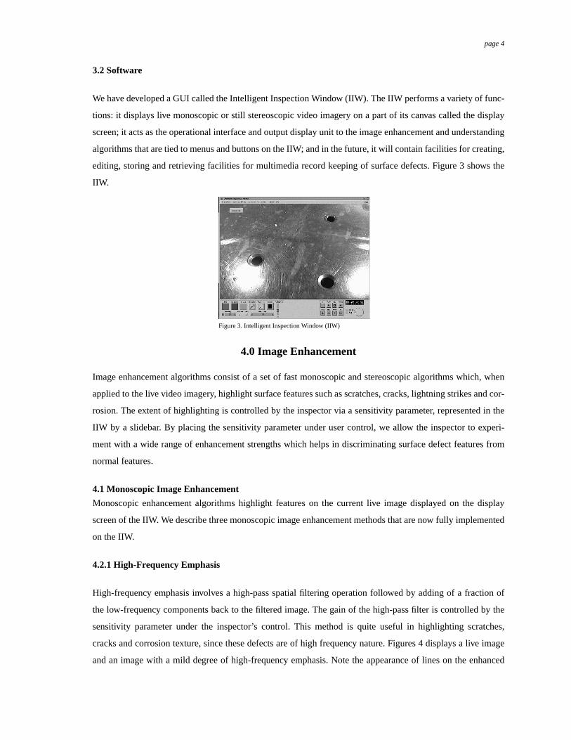
We have developed a GUI called the Intelligent Inspection Window (IIW). The IIW performs a variety of func-
tions: it displays live monoscopic or still stereoscopic video imagery on a part of its canvas called the display
screen; it acts as the operational interface and output display unit to the image enhancement and understanding
algorithms that are tied to menus and buttons on the IIW; and in the future, it will contain facilities for creating,
editing, storing and retrieving facilities for multimedia record keeping of surface defects. Figure 3 shows the
IIW.
< Fig 3 - Intelligent Inspection Window >
4.0 Image Enhancement
Image enhancement algorithms consist of a set of fast monoscopic and stereoscopic algorithms which, when
applied to the live video imagery, highlight surface features such as scratches, cracks, lightning strikes and cor-
rosion. The extent of highlighting is controlled by the inspector via a sensitivity parameter, represented in the
IIW by a slidebar. By placing the sensitivity parameter under user control, we allow the inspector to experi-
ment with a wide range of enhancement strengths which helps in discriminating surface defect features from
normal features.
4.1 Monoscopic Image Enhancement
Monoscopic enhancement algorithms highlight features on the current live image displayed on the display
screen of the IIW. We describe three monoscopic image enhancement methods that are now fully implemented
on the IIW.
4.2.1 High-Frequency Emphasis
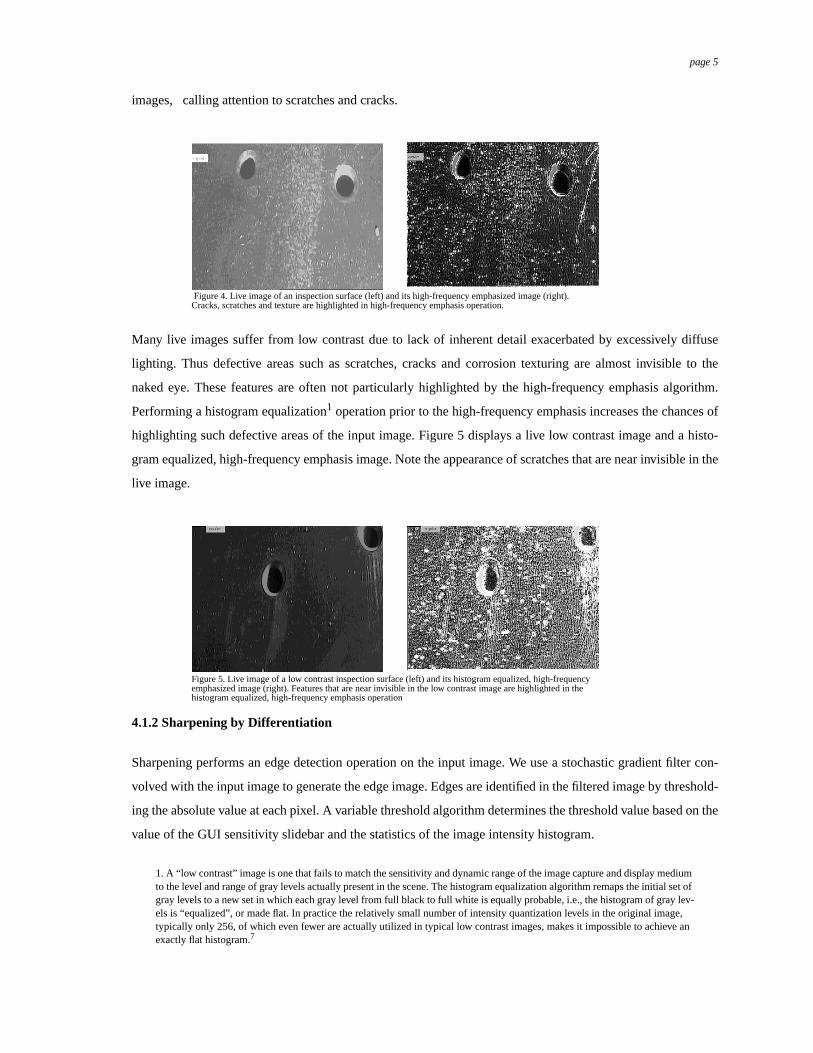
High-frequency emphasis involves a high-pass spatial filtering operation followed by adding of a fraction of
the low-frequency components back to the filtered image. The gain of the high-pass filter is controlled by the
sensitivity parameter under the inspector’s control. This method is quite useful in highlighting scratches,
cracks and corrosion texture, since these defects are of high frequency nature. Figures 4 displays a live image
and an image with a mild degree of high-frequency emphasis. Note the appearance of lines on the enhanced
Figure 3. Intelligent Inspection Window (IIW)
page 5
images, calling attention to scratches and cracks.
< Fig 4, 5 - high frequency emphasis >
Many live images suffer from low contrast due to lack of inherent detail exacerbated by excessively diffuse
lighting. Thus defective areas such as scratches, cracks and corrosion texturing are almost invisible to the
naked eye. These features are often not particularly highlighted by the high-frequency emphasis algorithm.
Performing a histogram equalization1 operation prior to the high-frequency emphasis increases the chances of
highlighting such defective areas of the input image. Figure 5 displays a live low contrast image and a histo-
gram equalized, high-frequency emphasis image. Note the appearance of scratches that are near invisible in the
live image.
4.1.2 Sharpening by Differentiation
Sharpening performs an edge detection operation on the input image. We use a stochastic gradient filter con-
volved with the input image to generate the edge image. Edges are identified in the filtered image by threshold-
ing the absolute value at each pixel. A variable threshold algorithm determines the threshold value based on the
value of the GUI sensitivity slidebar and the statistics of the image intensity histogram.
1. A “low contrast” image is one that fails to match the sensitivity and dynamic range of the image capture and display mediumto the level and range of gray levels actually present in the scene. The histogram equalization algorithm remaps the initial set ofgray levels to a new set in which each gray level from full black to full white is equally probable, i.e., the histogram of gray lev-els is “equalized”, or made flat. In practice the relatively small number of intensity quantization levels in the original image,typically only 256, of which even fewer are actually utilized in typical low contrast images, makes it impossible to achieve anexactly flat histogram.7
Figure 5. Live image of a low contrast inspection surface (left) and its histogram equalized, high-frequencyemphasized image (right). Features that are near invisible in the low contrast image are highlighted in thehistogram equalized, high-frequency emphasis operation
Figure 4. Live image of an inspection surface (left) and its high-frequency emphasized image (right).Cracks, scratches and texture are highlighted in high-frequency emphasis operation.
page 6
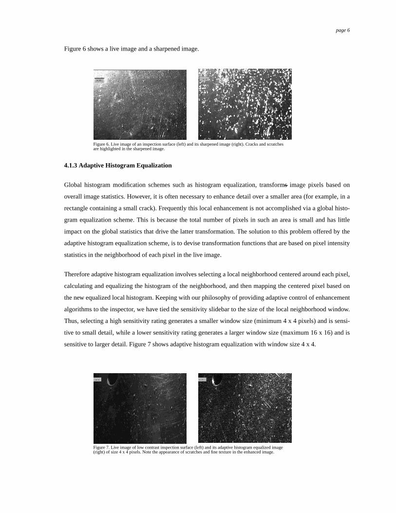
Figure 6 shows a live image and a sharpened image.
< Fig 6,7 - sharpening>
4.1.3 Adaptive Histogram Equalization
Global histogram modification schemes such as histogram equalization, transforms image pixels based on
overall image statistics. However, it is often necessary to enhance detail over a smaller area (for example, in a
rectangle containing a small crack). Frequently this local enhancement is not accomplished via a global histo-
gram equalization scheme. This is because the total number of pixels in such an area is small and has little
impact on the global statistics that drive the latter transformation. The solution to this problem offered by the
adaptive histogram equalization scheme, is to devise transformation functions that are based on pixel intensity
statistics in the neighborhood of each pixel in the live image.
Therefore adaptive histogram equalization involves selecting a local neighborhood centered around each pixel,
calculating and equalizing the histogram of the neighborhood, and then mapping the centered pixel based on
the new equalized local histogram. Keeping with our philosophy of providing adaptive control of enhancement
algorithms to the inspector, we have tied the sensitivity slidebar to the size of the local neighborhood window.
Thus, selecting a high sensitivity rating generates a smaller window size (minimum 4 x 4 pixels) and is sensi-
tive to small detail, while a lower sensitivity rating generates a larger window size (maximum 16 x 16) and is
sensitive to larger detail. Figure 7 shows adaptive histogram equalization with window size 4 x 4.
< Fig 8,9 - adaptive histogram equalization>
Figure 6. Live image of an inspection surface (left) and its sharpened image (right). Cracks and scratchesare highlighted in the sharpened image.
Figure 7. Live image of low contrast inspection surface (left) and its adaptive histogram equalized image(right) of size 4 x 4 pixels. Note the appearance of scratches and fine texture in the enhanced image.
page 7
4.2 Stereoscopic Image Enhancement
We have implemented two stereoscopic image enhancement methods on the IIW. They are:
• Stereoscopic high-frequency emphasis
• Augmented-stereoscopic high-frequency emphasis (an artificial exaggeration of the inherent stereo-scopic information content)
These algorithms sample the input video sources to capture the left and right images corresponding to the cur-
rent image displayed on the IIW. The captured images are processed individually by the specified algorithm
and displayed on the IIW display screen. The inspector views this screen stereoscopically through the active
eyeware that is synchronized with the display. We have included in the IIW, two slidebars that control the hor-
izontal and vertical disparities2 between the displayed left and right frames. The inspector, by adjusting these
slidebars to a desired level, can comfortably view the displayed frames stereoscopically.
4.2.1 Stereoscopic high-frequency emphasis
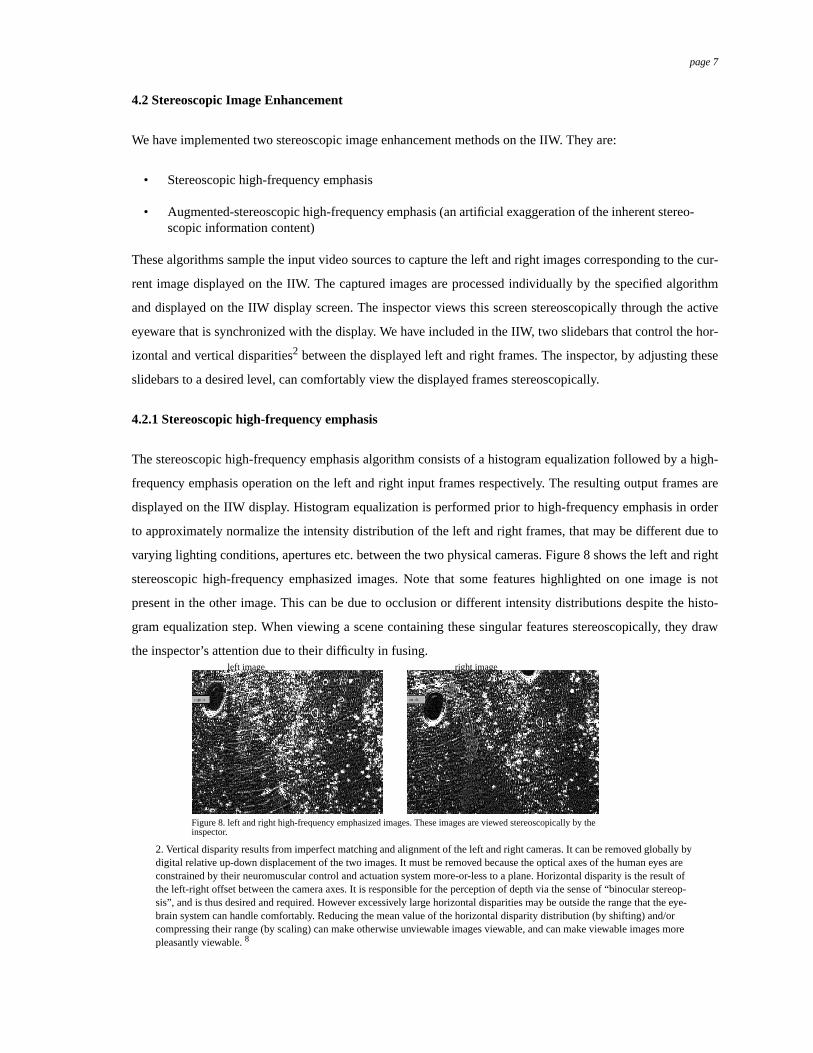
The stereoscopic high-frequency emphasis algorithm consists of a histogram equalization followed by a high-
frequency emphasis operation on the left and right input frames respectively. The resulting output frames are
displayed on the IIW display. Histogram equalization is performed prior to high-frequency emphasis in order
to approximately normalize the intensity distribution of the left and right frames, that may be different due to
varying lighting conditions, apertures etc. between the two physical cameras. Figure 8 shows the left and right
stereoscopic high-frequency emphasized images. Note that some features highlighted on one image is not
present in the other image. This can be due to occlusion or different intensity distributions despite the histo-
gram equalization step. When viewing a scene containing these singular features stereoscopically, they draw
the inspector’s attention due to their difficulty in fusing.
2. Vertical disparity results from imperfect matching and alignment of the left and right cameras. It can be removed globally bydigital relative up-down displacement of the two images. It must be removed because the optical axes of the human eyes areconstrained by their neuromuscular control and actuation system more-or-less to a plane. Horizontal disparity is the result ofthe left-right offset between the camera axes. It is responsible for the perception of depth via the sense of “binocular stereop-sis”, and is thus desired and required. However excessively large horizontal disparities may be outside the range that the eye-brain system can handle comfortably. Reducing the mean value of the horizontal disparity distribution (by shifting) and/orcompressing their range (by scaling) can make otherwise unviewable images viewable, and can make viewable images morepleasantly viewable.8
Figure 8. left and right high-frequency emphasized images. These images are viewed stereoscopically by theinspector.
left image right image
page 8
Thus, unexpectedly, these singular features along with the matched features, that represent the high-frequency
content of the left and right frames, are brought to the attention of the inspector by the stereoscopic high-fre-
quency emphasis algorithm.
4.2.2 Augmented-stereoscopic high-frequency emphasis
Augmented-stereoscopic imagery can be described as exaggerated stereoscopic imagery of a natural stereo-
scopic pair, realized by altering the natural disparity vector field. Augmented-stereoscopic imagery can be a
powerful visualization technique since it can make features stand out with respect to the background by chang-
ing the relevant disparity maps in a complex scene. The augmented-stereoscopic high-frequency emphasis
algorithm consists of four functional steps. The first two steps are similar to those of the stereoscopic high-fre-
quency emphasis algorithm, where the left and right frames are histogram equalized and run through a high-
frequency emphasis routine to locate the high frequency content. During the third step, the resulting left and
right high-pass filtered frames are thresholded to generate the left and right binary feature maps. In the final
step, the feature maps are overlaid with an offset that controls the extent of stereoscopic exaggeration (amount
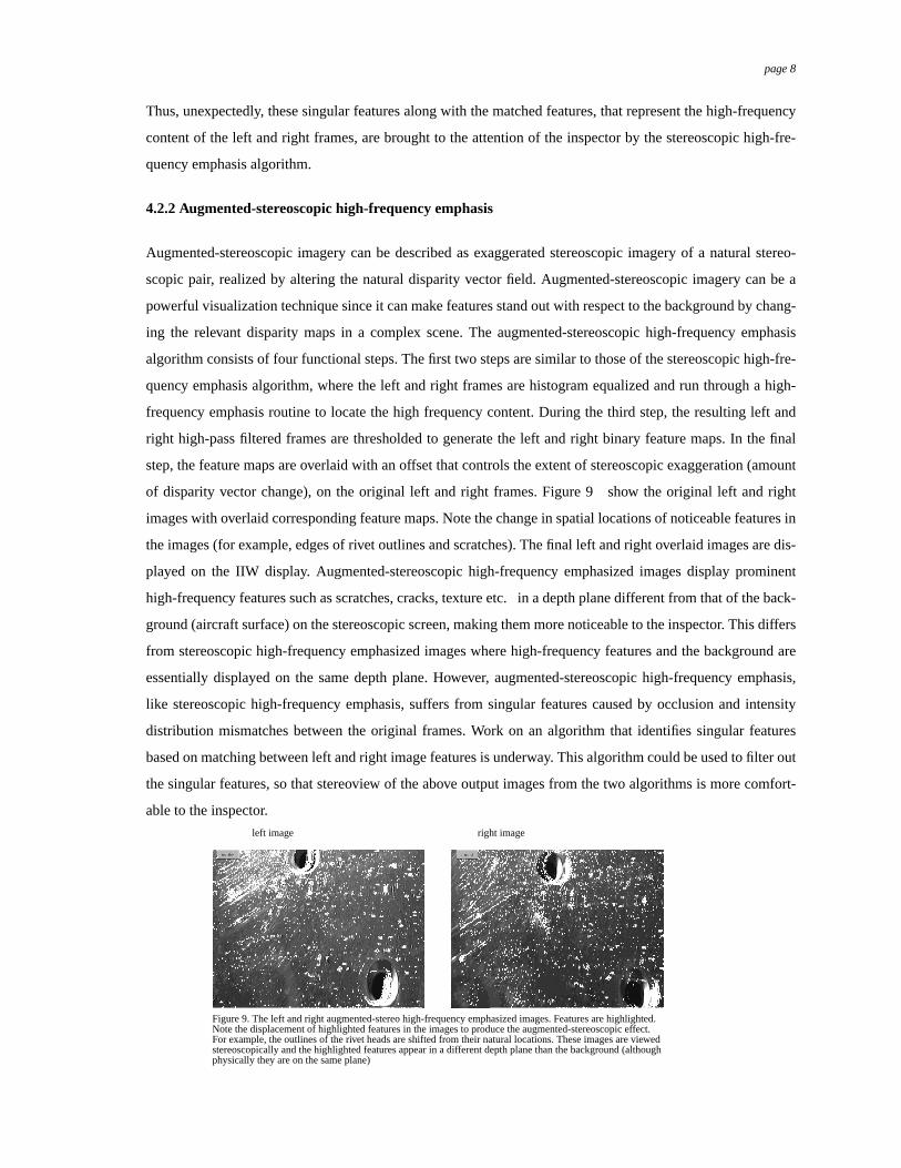
of disparity vector change), on the original left and right frames. Figure 9 show the original left and right
images with overlaid corresponding feature maps. Note the change in spatial locations of noticeable features in
the images (for example, edges of rivet outlines and scratches). The final left and right overlaid images are dis-
played on the IIW display. Augmented-stereoscopic high-frequency emphasized images display prominent
high-frequency features such as scratches, cracks, texture etc. in a depth plane different from that of the back-
ground (aircraft surface) on the stereoscopic screen, making them more noticeable to the inspector. This differs
from stereoscopic high-frequency emphasized images where high-frequency features and the background are
essentially displayed on the same depth plane. However, augmented-stereoscopic high-frequency emphasis,
like stereoscopic high-frequency emphasis, suffers from singular features caused by occlusion and intensity
distribution mismatches between the original frames. Work on an algorithm that identifies singular features
based on matching between left and right image features is underway. This algorithm could be used to filter out
the singular features, so that stereoview of the above output images from the two algorithms is more comfort-
able to the inspector.
<Fig 12, 13, 14, 15 - Augmented-stereoscopic high-frequency emphasis >
Figure 9. The left and right augmented-stereo high-frequency emphasized images. Features are highlighted.Note the displacement of highlighted features in the images to produce the augmented-stereoscopic effect.For example, the outlines of the rivet heads are shifted from their natural locations. These images are viewedstereoscopically and the highlighted features appear in a different depth plane than the background (althoughphysically they are on the same plane)
left image right image
page 9
5. Image Understanding
Enhancement algorithms emphasize image features such as spatial high frequencies. Since aircraft surface
defects such as cracks and surface corrosion are inherently of a high frequency nature, applying enhancement
algorithms to imagery results in these defects being highlighted. However, also included in the set of empha-
sized features are normal features such as scratches, rivet heads, paint cracks and transitions, discoloration, dirt
etc. due to their high frequency nature. Hence, it is left to the inspector’s judgement, a function of talent and
experience, to separate the skin defects from the normal features. The goal of image understanding algorithms
is to combine to some extent, the image enhancement and the complex human interpretation process into a sin-
gle program module. The recognition capability for surface flaws by an image understanding algorithm is
achieved by correlating enhanced features of live imagery with a prior or learned knowledge of material flaws.
However, developing a successful image understanding algorithm remains a rather difficult research challenge
due to its dependence on many factors such as algorithm architecture, defect and normal feature characteriza-
tion, a priori knowledge, learning and testing environments etc.
One possible scenario for application of image understanding algorithms is screening large volumes of image
data. The image understanding algorithm can conservatively label all plausible defects, so that the inspector
separates a larger fraction of actual defects from normal features in a smaller volume of raw data. Another sce-
nario is the interactive use of these algorithms by inspectors to obtain a second opinion about a particular sus-
picious feature. The latter possibility is most attractive when the real-time inspector is relatively inexperienced,
in general or with respect to a specific problem, compared to the inspector or inspectors whose expertise has
been incorporated (explicitly or implictly) in the algorithm; in this case the computer fulfills a training role in
addition to its direct inspection role.
5.1 Current work in Image Understanding Algorithms
Aircraft surface defects are characterized by their 2D and 3D features. For example, surface corrosion exhibits
texture which is prominent as a 2D feature, whereas a surface dent or an area with subsurface corrosion creates
a change in local surface curvature that is prominent as a 3D feature. A comprehensive image understanding
algorithm needs to consider both types of features in its analysis and recognition of surface defects. Our image
understanding algorithm extracts 2D and 3D features from the combination of live imagery that is displayed on
the IIW and a range map generated by an active vision sensor.
We extract 2D edges and texture from the live imagery using a multiresolution, multiorientation wavelet
framework. Edges are interesting features since they point to potential surface cracks, critical scratches and
broken rivets. Texture is an interesting feature due to its high correlation with subsurface corrosion, lightning
strikes etc. Unfortunately, live imagery contains countless number of edges and textures caused by simple
scratches, lighting, repair patches, rivets etc. The challenge is thus to separate the interesting edges and texture
page 10
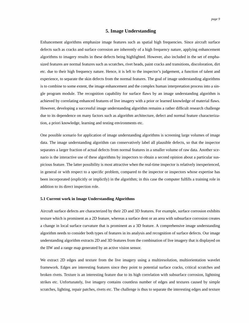
suggestive of defects from the rest. We achieve this within our wavelet framework by evaluating the strength of
such features along the resolution axis. By arguing, that in general, image cracks are localized (tiny) and
extend outwards from rivets, we are able to separate edges suggestive of cracks from normal edges (scratches,
rivet head outlines etc.). Figures 10 -12 illustrates a section of aircraft surface, normal edges found by running
our algorithm on the initial image and reduced pool of edges that may contain cracks. Note that the normal
edges contain the outlines of rivet heads, scratches and a paint change. Similar work for recognition of texture
indicative of corrosion is currently underway. The ability to discriminate features into probable defective fea-
tures and normal features is important because it drastically reduces the feature pool that needs to be further
processed to identify surface defects.
<Fig 16 - 18, edge discrimination>
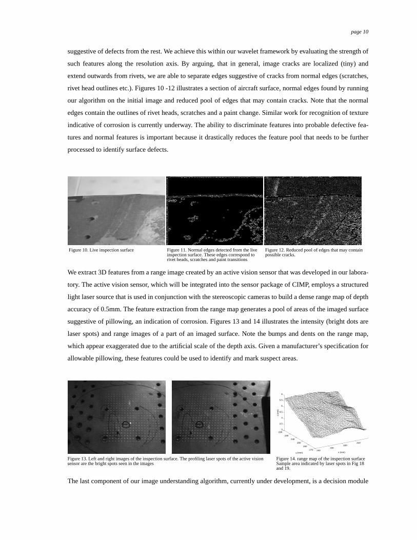
We extract 3D features from a range image created by an active vision sensor that was developed in our labora-
tory. The active vision sensor, which will be integrated into the sensor package of CIMP, employs a structured
light laser source that is used in conjunction with the stereoscopic cameras to build a dense range map of depth
accuracy of 0.5mm. The feature extraction from the range map generates a pool of areas of the imaged surface
suggestive of pillowing, an indication of corrosion. Figures 13 and 14 illustrates the intensity (bright dots are
laser spots) and range images of a part of an imaged surface. Note the bumps and dents on the range map,
which appear exaggerated due to the artificial scale of the depth axis. Given a manufacturer’s specification for
allowable pillowing, these features could be used to identify and mark suspect areas.
The last component of our image understanding algorithm, currently under development, is a decision module
Figure 10. Live inspection surface Figure 11. Normal edges detected from the live inspection surface. These edges correspond to
Figure 12. Reduced pool of edges that may contain possible cracks.
rivet heads, scratches and paint transitions
210220
230240
220
230
240
250
260
270
3
3.5
4
4.5
5
5.5
6
x (mm)y (mm)
z (m
m)
Figure 13. Left and right images of the inspection surface. The profiling laser spots of the active vision Figure 14. range map of the inspection surfaceSample area indicated by laser spots in Fig 18and 19.
.sensor are the bright spots seen in the images
page 11
that binds the 2D and 3D feature extraction and analysis algorithms. This module takes a feature pool sugges-
tive of defects generated by the separate 2D and 3D feature extraction and analysis routines described above,
and uses its a priori and learned knowledge to recognize surface defects.
6. Field Results of CIMP
We have very successfully demonstrated CIMP’s remote imaging capability to Northwest Airlines, USAir and
US Air Force NDI Program Office, in our lab and at Northwest’s Minneapolis 747 maintenance and inspection
facility. The IIW and the library of image enhancement and understanding algorithms were not part of the
demonstration at Northwest, since they are still under early development. Our demonstration proved that state-
of-the-art 3D stereoscopic video technology, expertly implemented by us and operated by inspectors not spe-
cifically trained in its use, delivers imagery of sufficiently high visual quality that aircraft inspectors and NDI
supervisors will accept it (and sometimes prefer it) as an alternative to direct visual inspection. Discussions
with aircraft inspectors and NDI supervisors strongly indicate that they consider image enhancement for
increased visibility of flaws to be valuable. However, they are skeptical about the feasibility of automated flaw
detection through image understanding algorithms, but consider it a worthwhile research goal.
7. Conclusion
Our research efforts are directed at testing the hypothesized feasibility and advantages of remote visual inspec-
tion of aircraft surfaces. To test this premise, we have built CIMP, a prototype mobile robot that carries a
remote imaging system, designed a GUI based inspection console, and are developing a library of image
enhancement and understanding algorithms that together support remote visual inspection. Through field test-
ing, we have demonstrated successfully that our remote live stereoscopic system delivers imagery of suffi-
ciently high visual quality that aircraft inspectors are willing to accept it as an alternative to direct visual
inspection. In this paper, we describe our efforts in the development of image enhancement and understanding
algorithms. We believe that cooperative inspection involving men and computers working together, where
application of these algorithms could be an early example, could contribute significantly to improving proba-
bility of flaw detection (POD), minimum detectable anomaly (MDA), and other quantitative and qualitative
measures of successful and productive inspection activity.
8. Acknowledgment
The authors wish to thank Alan Guisewite for his technical support and encouragement. This research was
funded by the Ben Franklin Technology Center of Western Pennsylvania grant RR 10032.
page 12
9. References
1. I. L. Davis and M. W. Siegel, "Automated Nondestructive Inspector of Aging Aircraft",Interna-tional Symposium on Measurement Technology and Intelligent Instruments, Huazhong Universityof Science and Technology, Wuhan, Hubei Province, People’s Republic of China, October 1993.
2. W. T. Shepherd, "Human factors in aircraft maintenance and inspection",Conference on aging air-craft and structural airworthiness, NASA conference Publication 3160, pp 301-304, 1991.
3. M. W. Siegel, "Automation for Nondestructive Inspection of Aircraft",Conference on IntelligentRobots in Field, Factory, Service and Space (CIRFFSS’94), Paul J Weitz (NASA/JSC), ed., AIAA,AIAA/NASA, pp. 367 - 377, Houston TX, March 1994.
4. M. W. Siegel, W. M. Kaufman, C. J. Alberts, "Mobile Robots for Difficult Measurements in Diffi-cult Environments: Application to Aging Aircraft Inspection", Robotics and Autonomous Systems,Vol. 11, pp 187 - 194, July 1993.
5. V. S. Grinberg, G. W. Podnar, and M. W. Siegel, "Geometry of Binocular Imaging",Proceedings ofthe SPIE/IST Conference (San Jose), ed., SPIE/IST, SPIE/IST, February 1994.
6. V. S. Grinberg, G. W. Podnar, and M. W. Siegel, "Geometry of Binocular Imaging ll: The Aug-mented Eye",Proceedings of the SPIE/IST Conference (San Jose), ed., SPIE/IST, SPIE/IST, Febru-ary 1995.
7. R. C. Gonzalez and P. Wintz,Digital Image Processing, Second Edition, Addison-Wesley, 1987.
8. J. S. McVeigh, M. W. Siegel and A. G. Jordan, "Algorithm for automated eye strain reduction inreal stereoscopic images and sequences",Proceedings of the SPIE/IST Conference (San Jose), ed.,SPIE/IST, SPIE/IST, February 1996.