Embed Size (px)
Citation preview

50 Greenfield StreetGreenfield, MA 01301T (413) 772-0846 F (413) 772-6729Email: [email protected]
BETE Fog Nozzle, Inc.
PERFORMANCE THROUGH ENGINEERING
ABSORPTION • ADDITIVES • AERATION • AIR AND STEAM • AIR CONDITIONING • AIR NOZZLES
• BIODIESEL • BLOWOFF NOZZLES • CLEAN-IN-PLACE NOZZLES • CLOG-RESISTANT NOZZLES
• COATING • CONCRETE CURING • COOLING • DISTRIBUTION • DRYING • DUST CONTROL
• ETCHING • EVAPORATIVE COOLING • EVAPORATIVE DISPOSAL • FIRE PROTECTION • FLUE GAS
DESULPHURIZATION • FOAM CONTROL • FOG NOZZLES • FOOD PROCESSING • GAS SCRUBBING
• HUMIDIFICATION • LUBRICATION • MIST ELIMINATOR WASH • MISTING • MIXING
EDUCTORS • MOISTENING • ODOR CONTROL • PACKING • PARTS WASHING
• PETROLEUM PROCESSING • POLLUTION CONTROL • PULP BLEACHING • QUENCH
• ROLL COOLING • SCRUBBING • SPRAY DRYING • TANK WASHING • WASTEWATER TREATMENT
0707 10K 120METRIC
www.bete.com
ww
w.b
ete.com
IN
DU
STRIA
L SPRA
Y N
OZZLES
120METR
IC Prin
ted in
U.S.A
.
Flow rate
Q = K (P) x
P = (Q)1/X
K
(Q2)Q1 = (P2) X
P1
(Q2)Q1 = √ SG1
SG2
Vessel with internal pressure:
l/min = K (P inlet - P Vessel )x
Terms and Conditions.Prices quoted are FOB, Greenfield, MA. Terms are 1%/10 net 30 days for approved ac-counts. Minimum order is $50.00 net. A restocking charge of 15% will apply for standardproduct accepted for return up to one year from the date of purchase. BETE FOG NOZZLEreserves the right to charge interest on past-due accounts. No goods may be returned with-out prior authorization. Non-Standard items are not subject to return.
BETE FOG NOZZLE reserves the right to make changes in specifications or design at anytime without notice. Illustrations shown in this catalog are for information only.Warranty - all goods are warranteed for good workmanship in accordance with industrystandard and will perform in accordance with the products specification.Limitation of Liability - BETE’s liability shall be limited to the value of the product billedarising from a purchase order.
Conversion DataMULTIPLY BY TO OBTAINfeet/sec 18.29 meters/min
feet of water 0.0295 atmospheres
feet of water 0.884 inches of mercury
feet of water 0.433 psi
gallons 3785 cm3
gallons 0.1337 ft3
gallons 0.83267 imperial gallons
gallons 3.785 liters
gallons/min 0.06309 liters/sec
imperial gallons 1.2 gallons
horsepower 1.014 horsepower (metric)
horsepower 33.000 foot pounds/min
horsepower 746 Watts
inches 2.54 centimeters
kg/cm2 14.22 psi
kiloWatts 1.340 horsepower
liters 1000 cm3
liters 0.264 gallons
liters 0.22 imperial gallons
liters 33.8 ounces (fluid)
meters 3.281 feet
microns (µm) 0.0394 thousandth of an inch
miles/hr 44.7 centimeters/sec
miles/hr 1.467 feet/sec
millimeters 0.0394 inches
psi 0.068 atmospheres
psi 0.06895 bar
psi 2.307 feet of water
psi 0.0703 kg/cm2
psi 6.895 kPa
Conversion DataMULTIPLY BY TO OBTAINatmospheres 1.013 bar
atmospheres 33.931 feet of water
atmospheres 1.0332 kg/cm2
atmospheres 101.3 kiloPascals (kPa)
atmospheres 14.696 psi
bar 100 kPa
bar 14.5 psi
barrels (oil) 42 gallons
centimeters 0.3937 inches
centiStokes Sp. gravity centiPoise
cm3 0.061 in3
cm3 0.000264 gallons
cm3 0.001 liters
ft3 1728 inches
ft3 0.02832 m3
ft3 7.48 gallons
ft3 28.32 liters
ft3 (water) 62.43 pounds (water)
in3 16.39 cm3
in3 0.00433 gallons
in3 0.164 liters
m3 35.31 ft3
m3 61.024 in3
m3 264.2 gallons
m3 1000 liters
degree (angle) 60 minutes
degree (Celsius) (°C x 1.8) +32 degree (Fahrenheit)
degree (Fahrenheit) (°F-32) x 0.56 degree (Celsius)
feet 0.3048 meters
feet/sec 30.48 centimeters/sec
Nozzle Exponent Nozzle ExponentSeries x Series xBJ 0.50 PJ 0.50CW 0.47 PSR 0.50FF 0.50 SC 0.47IS 0.50 SPN 0.50L 0.50 ST 0.50LEM 0.50 STXP 0.50LP 0.50 TC 0.46MaxiPass 0.47 TD/TDL 0.50MicroWhirl 0.50 TF 0.50N 0.50 TFXP 0.50NC 0.47 TH, THW 0.50NCJ 0.47 TW 0.50NCK 0.47 WL 0.47NCS 0.47 WT 0.50NF 0.50 WTX 0.50P 0.50 WTZ 0.50
Dropsize System Design
(D2D1
) = (P2)-0.3 PPump = PNozzle + PPipe Losses + ρρgh
100000P1
www.BETE.com
Conversions & EquationsTable of Contents
With thousands of different spray nozzles available in hundreds of different materials, it’s often hard to know where to start. So, we’ve incorporated a number of uniquecharts and other aids into this catalog to simplify your selection process.
Still unsure of which nozzle to use? We can help. Use the BETEApplication Intake Sheet on page 109 to describe your application to our engineers. We’ll put our years of experience to work on yourproblem and respond quickly with a recommendation.
120METRIC
Cover photography by Ed Judice and Greg Bardwell.
Payment with Visa, Mastercard and AmericanExpress accepted.
a b d
Nozzle Selection GuideHow to order
There are many ways to select a nozzle. Which way is right for you?
Do you know the spray pattern, but not the type of nozzle?..................see pages 2, 3This section introduces you to the several types of spray nozzles and the spray patterns available from each.
Do you know what style of nozzle is right for you but need help differentiating betweenthe many nozzle series in each style?..........................................................see pages 4, 5Organized by nozzle style, this section briefly describes each nozzle series
Want to see what nozzles excel at your specific application?.................see pages 6-12An alphabetical list of common applications and the nozzles that are used most frequently for each.
Still not sure? Don’t have time to look? Call us. BETE’s Customer Service Representatives and Application Engineers will listen to your problem and guide you to the nozzle you need.Let our expertise save you time and keep your process running at peak efficiency.
www.bete.com
BY SPRAY PATTERN....PP. 2, 3
BY NOZZLE TYPE....PP. 4, 5
BY APPLICATION....PP. 6-12
1-800-235-00491-413-772-0846
©2007 BETE Fog Nozzle, Inc. All rights reserved.
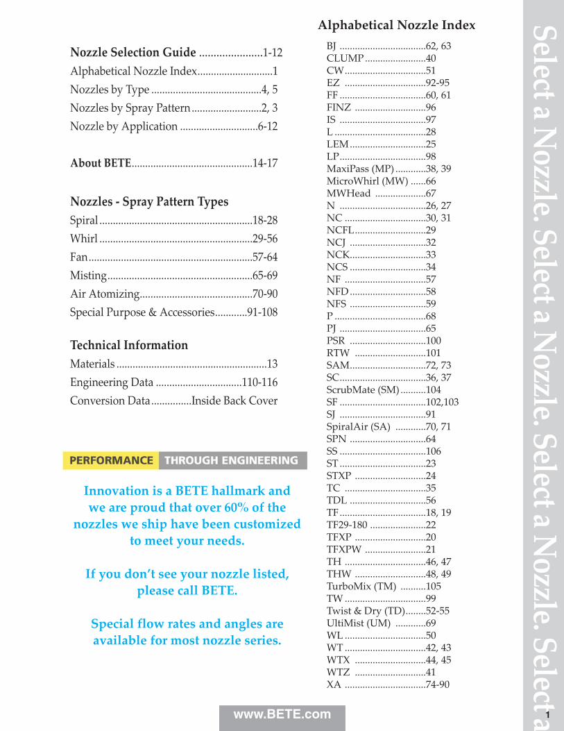
Alphabetical Nozzle IndexBJ ..................................62, 63CLUMP ........................40CW................................51EZ ................................92‑95FF ..................................60, 61FINZ ............................96IS ..................................97L ....................................28LEM..............................25LP..................................98MaxiPass (MP) ............38, 39MicroWhirl (MW) ......66MWHead ....................67N ..................................26, 27NC ................................30, 31NCFL............................29NCJ ..............................32NCK..............................33NCS ..............................34NF ................................57NFD..............................58NFS ..............................59P ....................................68PJ ..................................65PSR ..............................100RTW ............................101SAM..............................72, 73SC..................................36, 37ScrubMate (SM) ..........104SF ..................................102,103SJ ..................................91SpiralAir (SA) ............70, 71SPN ..............................64SS ..................................106ST ..................................23STXP ............................24TC ................................35TDL ..............................56TF..................................18, 19TF29‑180 ......................22TFXP ............................20TFXPW ........................21TH ................................46, 47THW ............................48, 49TurboMix (TM) ..........105TW ................................99Twist & Dry (TD)........52‑55UltiMist (UM) ............69WL ................................50WT ................................42, 43WTX ............................44, 45WTZ ............................41XA ................................74‑90
www.BETE.com
Select a Nozzle. Select a N
ozzle. Select a Nozzle. Select a
Nozzle Selection Guide ......................1‑12Alphabetical Nozzle Index............................1Nozzles by Type .........................................4, 5Nozzles by Spray Pattern ..........................2, 3Nozzle by Application .............................6‑12
About BETE.............................................14‑17
Nozzles ‑ Spray Pattern TypesSpiral .........................................................18‑28Whirl .........................................................29‑56Fan.............................................................57‑64Misting......................................................65‑69Air Atomizing..........................................70‑90Special Purpose & Accessories............91‑108
Technical InformationMaterials ........................................................13Engineering Data ................................110‑116Conversion Data...............Inside Back Cover
Innovation is a BETE hallmark and we are proud that over 60% of the
nozzles we ship have been customizedto meet your needs.
If you don’t see your nozzle listed,please call BETE.
Special flow rates and angles areavailable for most nozzle series.
1
Noz
zle.
Sele
ct a N
ozzl
e. Se
lect
a Noz
zle.
Sele
ct a N
ozzl
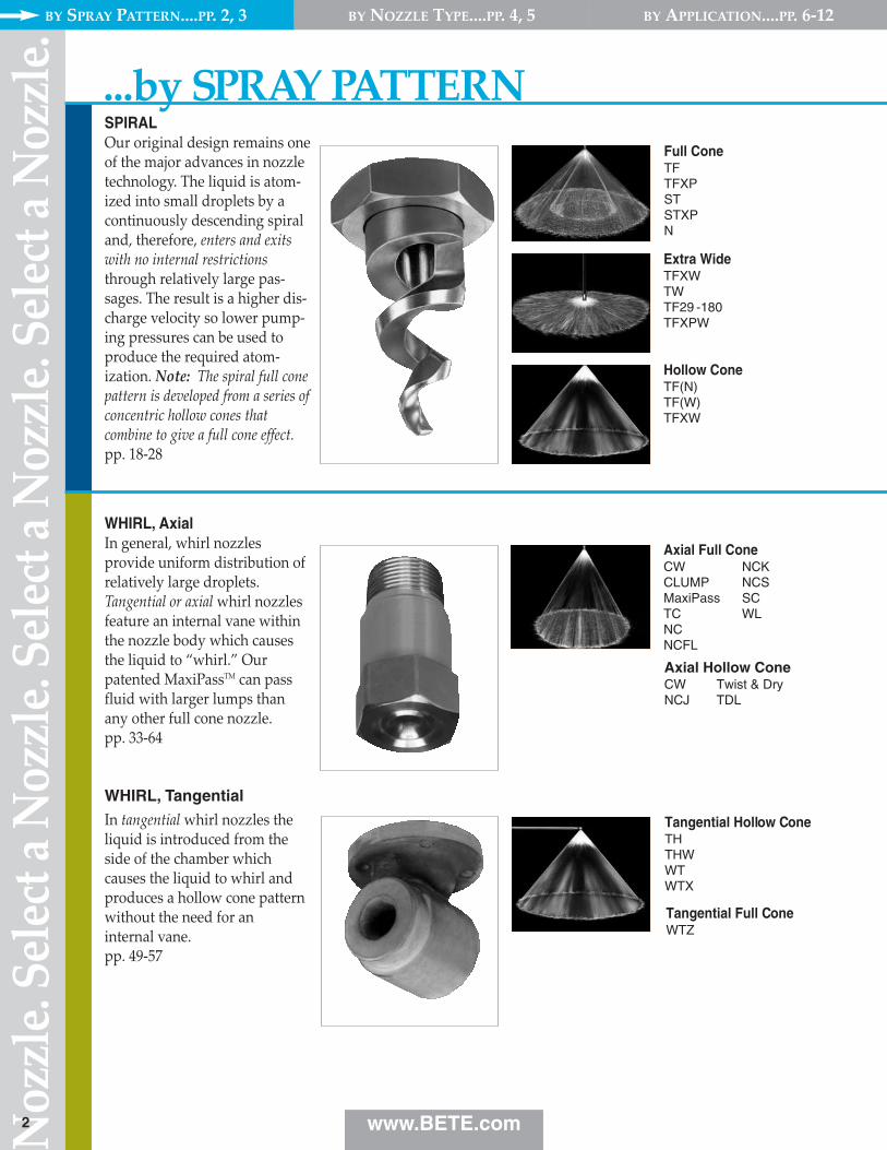
e. SPIRAL Our original design remains oneof the major advances in nozzletechnology. The liquid is atom‑ized into small droplets by acontinuously descending spiraland, therefore, enters and exitswith no internal restrictionsthrough relatively large pas‑sages. The result is a higher dis‑charge velocity so lower pump‑ing pressures can be used toproduce the required atom‑ization. Note: The spiral full conepattern is developed from a series ofconcentric hollow cones thatcombine to give a full cone effect.pp. 18‑28
Full ConeTFTFXPSTSTXPN
Extra WideTFXWTWTF29 -180TFXPW
Hollow Cone TF(N)TF(W)TFXW
WHIRL, AxialIn general, whirl nozzlesprovide uniform distribution ofrelatively large droplets.Tangential or axial whirl nozzlesfeature an internal vane withinthe nozzle body which causesthe liquid to “whirl.” Ourpatented MaxiPassTM can passfluid with larger lumps thanany other full cone nozzle.pp. 33‑64
Axial Full Cone CW NCKCLUMP NCSMaxiPass SCTC WLNCNCFL
Axial Hollow ConeCW Twist & DryNCJ TDL
Tangential Hollow ConeTHTHWWTWTX
2
WHIRL, TangentialIn tangential whirl nozzles theliquid is introduced from theside of the chamber whichcauses the liquid to whirl andproduces a hollow cone patternwithout the need for aninternal vane.pp. 49‑57
...by SPRAY PATTERN
Tangential Full ConeWTZ
www.BETE.com
BY SPRAY PATTERN....PP. 2, 3 BY NOZZLE TYPE....PP. 4, 5 BY APPLICATION....PP. 6‑12
Select a Nozzle. Select a N
ozzle. Select a Nozzle. Select a
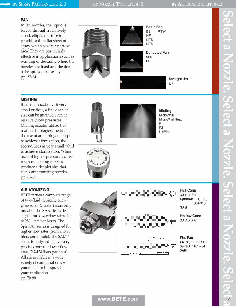
FANIn fan nozzles, the liquid isforced through a relativelysmall, elliptical orifice toprovide a thin, flat sheet ofspray which covers a narrowarea. They are particularlyeffective in applications such aswashing or descaling where thenozzles are fixed and the itemto be sprayed passes by.pp. 57‑64
Basic FanBJ RTWNFNFDNFS
Deflected FanSPNFF
Straight JetNF
MISTINGBy using nozzles with verysmall orifices, a fine dropletsize can be attained even atrelatively low pressures.Misting nozzles utilize twomain technologies; the first isthe use of an impingement pinto achieve atomization, thesecond uses as very small whirlto achieve atomization. Whenused at higher pressures, directpressure misting nozzlesproduce a droplet size thatrivals air atomizing nozzles.pp. 65‑69
MistingMicroWhirlMicroWhirl HeadPPJUltiMist
AIR ATOMIZINGBETE carries a complete rangeof two‑fluid (typically com‑pressed air & water) atomizingnozzles. The XA series is de‑signed for lower flow rates (1.0to 280 liters per hour). TheSpiralAir series is designed forhigher flow rates (from 2 to 80liters per minute). The SAMTM
series is designed to give veryprecise control at lower flowrates (2.7‑174 liters per hour).All are available in a widevariety of configurations, so you can tailor the spray to your application.pp. 70‑90
Full ConeXA PR, SRSpiralAir 101, 103,
304-310SAM
Hollow ConeXA AD, XW
Flat FanXA PF, FF, EF,SFSpiralAir 401-404SAM
3www.BETE.com
BY SPRAY PATTERN....PP. 2, 3 BY NOZZLE TYPE....PP. 4, 5 BY APPLICATION....PP. 6‑12
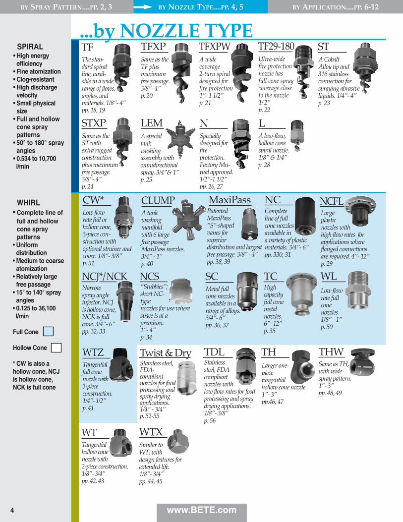
TFThe stan‑dard spiralline, avail‑able in a wide range of flows,angles, and materials. 1/8”‑ 4”pp. 18, 19
TFXPSame as the TF plus maximum free passage.3/8”‑ 4” p. 20
NSpeciallydesigned forfireprotection.Factory Mu‑tual approved.1/2”‑1 1/2”pp. 26, 27
LA low‑flow,hollow cone spiral nozzle. 1/8” & 1/4” p. 28
LEMA specialtankwashingassembly withomnidirectionalspray. 3/4”& 1”p. 25
SPIRAL • High energy
efficiency• Fine atomization• Clog-resistant• High discharge
velocity• Small physical
size• Full and hollow
cone spraypatterns
• 50° to 180° sprayangles
• 0.534 to 10,700 l/min
WHIRL• Complete line of
full and hollowcone spraypatterns
• Uniformdistribution
• Medium to coarseatomization
• Relatively largefree passage
• 15° to 140° sprayangles
• 0.125 to 36,100l/min
Full Cone
Hollow Cone
* CW is also ahollow cone, NCJis hollow cone,NCK is full cone
NCFLLarge plastic nozzles withhigh flow rates forapplications whereflanged connectionsare required. 4”‑ 12” p. 29
NCCompleteline of fullcone nozzlesavailable ina variety of plasticmaterials. 3/4”‑ 6” pp. 330, 31
Narrow spray angle injector. NCJ is hollow cone, NCK is full cone. 3/4”‑ 6” pp. 32, 33
TCHighcapacityfull conemetalnozzles. 6”‑ 12” p. 35
SCMetal fullcone nozzles available in a widerange of alloys. 3/4”‑ 6”pp. 36, 37
MaxiPassPatentedMaxiPass“S”‑shapedvanes forsuperiordistribution and largestfree passage. 3/8” ‑ 4”pp. 38, 39
WTXSimilar toWT, withdesign features forextended life. 1/8”‑ 3/4”pp. 44, 45
THLarger one‑piecetangentialhollow cone nozzle1”‑ 3” pp.46, 47
THWSame as TH,with widespray pattern.1”‑ 3”pp. 48, 49
A tankwashingmanifoldwith 6 largefree passageMaxiPass nozzles. 3/4” ‑ 1” p. 40
NCS“Stubbies”;short NC‑typenozzles for use wherespace is at apremium. 1”‑ 4” p. 34
WTZ
4 www.BETE.com
A wide coverage2‑turn spiraldesigned for fire protection1”‑ 1 1/2”p. 21
STXPSame as the ST with extra ruggedconstruction plus maximum free passage. 3/8”‑ 4” p. 24
STA Cobalt Alloy tip and 316 stainlessconnection forspraying abrasiveliquids. 1/4”‑ 4”p. 23
WLLow flowrate fullconenozzles. 1/8” ‑ 1” p. 50
CW*Low flowrate full orhollow cone,3‑piece con‑struction withoptional strainer andcover. 1/8”‑ 3/8” p. 51
CLUMP
WTTangentialhollow conenozzle with 2‑piece construction. 1/8”‑ 3/4”pp. 42, 43
TFXPWUltra‑wide fire protection nozzle has full cone spraycoverage close to the nozzle1/2”p. 22
TF29‑180...by NOZZLE TYPE
NCJ*/NCK
Twist & DryStainless steel,FDA‑compliantnozzles for foodprocessing andspray dryingapplications. 1/4” ‑ 3/4” p. 52‑55
TDLStainlesssteel, FDAcompliantnozzles withlow flow rates for foodprocessing and spraydrying applications.1/8”‑ 3/8” p. 56
Tangential full cone nozzle with 3‑piece construction. 1/4”‑ 1/2”p. 41
BY SPRAY PATTERN....PP. 2, 3 BY NOZZLE TYPE....PP. 4, 5 BY APPLICATION....PP. 6‑12
5
Quickconnection system, ramped engage‑ment for auto‑matic alignment.1/8” ‑ 1/2” p. 92‑95
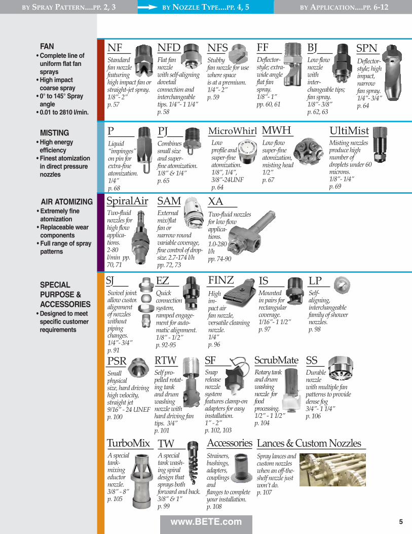
NFStandardfan nozzlefeaturinghigh impact fan orstraight‑jet spray.1/8”‑ 2” p. 57
BJLow flownozzle with inter‑changeable tips;fan spray.1/8”‑ 3/8”p. 62, 63
FFDeflector‑style; extra‑wide angle flat fan spray.1/8”‑ 1”pp. 60, 61
SPNDeflector‑style; highimpact,narrowfan spray. 1/4”‑ 3/4”p. 64
PLiquid“impinges”on pin forextra‑fineatomization.1/4”p. 68
PJ
SpiralAir XATwo‑fluid nozzles for low flow applica‑tions.1.0‑280 l/h pp. 74‑90
ISMountedin pairs forrectangularcoverage. 1/16”‑ 1 1/2”p. 97
LPSelf‑aligning,interchangeablefamily of showernozzles. p. 98
A specialtank‑mixingeductornozzle. 3/8” ‑ 8”p. 105
SJSwivel jointsallow customalignment of nozzles without piping changes.1/4”‑ 3/4” p. 91
Stubbyfan nozzle for usewhere space is at a premium. 1/4”‑ 2” p. 59
NFDFlat fannozzlewith self‑aligningdovetailconnection andinterchangeabletips. 1/4”‑ 1 1/4” p. 58
NFS
TurboMixA specialtank wash‑ing spiraldesign thatsprays bothforward and back. 3/8” & 1”p. 99
TW
SFSnaprelease nozzle system features clamp‑onadapters for easyinstallation. 1” ‑ 2”p. 102, 103
EZ
SSDurablenozzlewith multiple fanpatterns to providedense fog 3/4”‑ 1 1/4”p. 106
Self pro‑pelled rotat‑ing tank and drum washing nozzle with hard driving fantips. 3/4”p. 101
RTWPSRSmallphysicalsize, hard drivinghigh velocity,straight jet9/16” ‑ 24 UNEFp. 100
Two‑fluidnozzles forhigh flow applica‑tions.2‑80l/min pp.70, 71
Combines small size and super‑fine atomization. 1/8” & 1/4”p. 65
ScrubMateRotary tankand drumwashingnozzle forfoodprocessing.1/2” ‑ 1 1/2”p. 104
UltiMistMisting nozzlesproduce highnumber ofdroplets under 60microns. 1/8”‑ 1/4”p. 69
FAN• Complete line of
uniform flat fansprays
• High impactcoarse spray
• 0° to 145° Sprayangle
• 0.01 to 2810 l/min.
AIR ATOMIZING• Extremely fine
atomization• Replaceable wear
components• Full range of spray
patterns
MISTING• High energy
efficiency• Finest atomization
in direct pressurenozzles
SPECIALPURPOSE &ACCESSORIES
• Designed to meetspecific customerrequirements
Highim‑pact airfan nozzle,versatile cleaningnozzle.1/4”p. 96
Externalmix/flatfan ornarrow roundvariable coverage,fine control of drop‑size. 2.7‑174 l/h pp. 72, 73
SAM
MWHLow flow super‑fine atomization, misting head1/2”p. 67
FINZ
www.BETE.com
MicroWhirl
BY SPRAY PATTERN....PP. 2, 3 BY NOZZLE TYPE....PP. 4, 5 BY APPLICATION....PP. 6‑12
AccessoriesStrainers,bushings,adapters,couplingsandflanges to completeyour installation. p. 108
Lances & Custom NozzlesSpray lances andcustom nozzleswhen an off‑the‑shelf nozzle justwon’t do. p. 107
Low profile andsuper‑fineatomization.1/8”, 1/4”, 3/8”‑24UNFp. 64
Noz
zle.
Sele
ct a N
ozzl
e. Se
lect
a Noz
zle.
Sele
ct a N
ozzl
e.
6
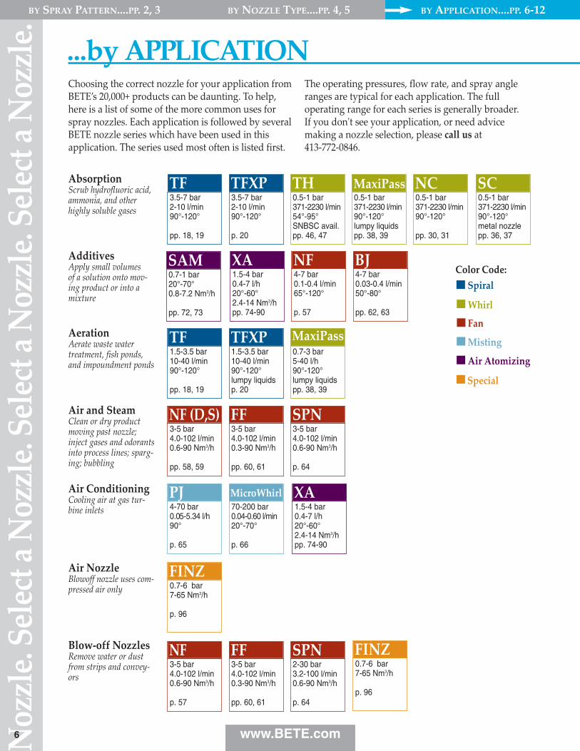
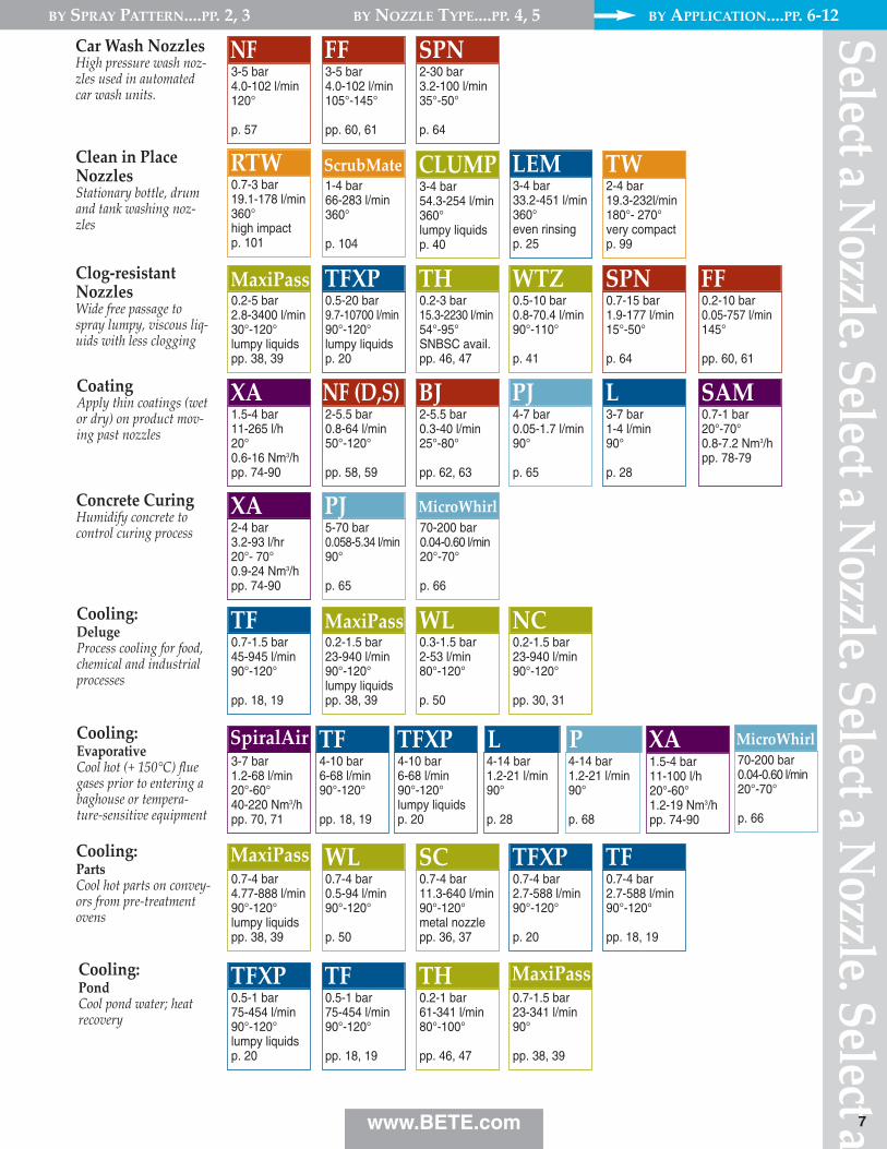
...by APPLICATIONChoosing the correct nozzle for your application fromBETE’s 20,000+ products can be daunting. To help,here is a list of some of the more common uses forspray nozzles. Each application is followed by severalBETE nozzle series which have been used in thisapplication. The series used most often is listed first.
The operating pressures, flow rate, and spray angleranges are typical for each application. The fulloperating range for each series is generally broader. If you don't see your application, or need advicemaking a nozzle selection, please call us at 413‑772‑0846.
Color Code:
AbsorptionScrub hydrofluoric acid, ammonia, and other highly soluble gases
AdditivesApply small volumes of a solution onto mov‑ing product or into amixture
AerationAerate waste water treatment, fish ponds,and impoundment ponds
Air ConditioningCooling air at gas tur‑bine inlets
Air and SteamClean or dry productmoving past nozzle;inject gases and odorantsinto process lines; sparg‑ing; bubbling
3.5-7 bar2-10 l/min90°-120°
pp. 18, 19
TF
1.5-4 bar0.4-7 l/h20°-60°2.4-14 Nm3/hpp. 74-90
XA
1.5-3.5 bar10-40 l/min90°-120°
pp. 18, 19
TF
3-5 bar4.0-102 l/min0.6-90 Nm3/h
pp. 58, 59
NF (D,S)
3.5-7 bar2-10 l/min90°-120°
p. 20
TFXP
4-7 bar0.1-0.4 l/min65°-120°
p. 57
NF
1.5-3.5 bar10-40 l/min90°-120°lumpy liquidsp. 20
TFXP
3-5 bar4.0-102 l/min0.3-90 Nm3/h
pp. 60, 61
FF
4-7 bar0.03-0.4 l/min50°-80°
pp. 62, 63
BJ
0.7-3 bar5-40 l/h90°-120°lumpy liquidspp. 38, 39
MaxiPass
3-5 bar4.0-102 l/min0.6-90 Nm3/h
p. 64
SPN
Blow‑off NozzlesRemove water or dustfrom strips and convey‑ors
3-5 bar4.0-102 l/min0.6-90 Nm3/h
p. 57
NF3-5 bar4.0-102 l/min0.3-90 Nm3/h
pp. 60, 61
FF2-30 bar3.2-100 l/min0.6-90 Nm3/h
p. 64
SPN
1.5-4 bar0.4-7 l/h20°-60°2.4-14 Nm3/hpp. 74-90
XA
Spiral
Whirl
Fan
Misting
Special
Air Atomizing
4-70 bar0.05-5.34 l/h90°
p. 65
PJ
0.5-1 bar371-2230 l/min90°-120°lumpy liquidspp. 38, 39
MaxiPass0.5-1 bar371-2230 l/min54°-95°SNBSC avail.pp. 46, 47
TH0.5-1 bar371-2230 l/min90°-120°
pp. 30, 31
NC0.5-1 bar371-2230 l/min90°-120°metal nozzlepp. 36, 37
SC
70-200 bar0.04-0.60 l/min20°-70°
p. 66
MicroWhirl
0.7-1 bar20°-70°0.8-7.2 Nm3/h
pp. 72, 73
SAM
Air NozzleBlowoff nozzle uses com‑pressed air only 0.7-6 bar
7-65 Nm3/h
p. 96
FINZ
www.BETE.com
BY SPRAY PATTERN....PP. 2, 3 BY NOZZLE TYPE....PP. 4, 5 BY APPLICATION....PP. 6‑12
0.7-6 bar7-65 Nm3/h
p. 96
FINZ
Select a Nozzle. Select a N
ozzle. Select a Nozzle. Select a 7
0.5-1 bar75-454 l/min90°-120°lumpy liquidsp. 20
TFXP0.5-1 bar75-454 l/min90°-120°
pp. 18, 19
TF0.2-1 bar61-341 l/min80°-100°
pp. 46, 47
THCooling:PondCool pond water; heatrecovery
0.7-1.5 bar23-341 l/min90°
pp. 38, 39
MaxiPass
CoatingApply thin coatings (wet or dry) on product mov‑ing past nozzles
Concrete CuringHumidify concrete tocontrol curing process
Cooling: DelugeProcess cooling for food,chemical and industrialprocesses
Cooling:EvaporativeCool hot (+ 150°C) flue gases prior to entering abaghouse or tempera‑ture‑sensitive equipment
Cooling:PartsCool hot parts on convey‑ors from pre‑treatmentovens
1.5-4 bar11-265 l/h20°0.6-16 Nm3/hpp. 74-90
XA
2-4 bar3.2-93 l/hr20°- 70°0.9-24 Nm3/hpp. 74-90
XA
0.7-1.5 bar45-945 l/min90°-120°
pp. 18, 19
TF
3-7 bar1.2-68 l/min20°-60°40-220 Nm3/hpp. 70, 71
SpiralAir
2-5.5 bar0.8-64 l/min50°-120°
pp. 58, 59
NF (D,S)
0.2-1.5 bar23-940 l/min90°-120°lumpy liquidspp. 38, 39
MaxiPass
0.7-4 bar4.77-888 l/min90°-120°lumpy liquidspp. 38, 39
MaxiPass
4-10 bar6-68 l/min90°-120°
pp. 18, 19
TF
0.5-20 bar9.7-10700 l/min90°-120°lumpy liquidsp. 20
TFXP0.2-5 bar2.8-3400 l/min30°-120°lumpy liquidspp. 38, 39
MaxiPass0.7-15 bar1.9-177 l/min15°-50°
p. 64
SPN
Car Wash NozzlesHigh pressure wash noz‑zles used in automatedcar wash units.
Clean in PlaceNozzlesStationary bottle, drumand tank washing noz‑zles
Clog‑resistantNozzlesWide free passage tospray lumpy, viscous liq‑uids with less clogging
4-7 bar0.05-1.7 l/min90°
p. 65
PJ
5-70 bar0.058-5.34 l/min90°
p. 65
PJ
0.3-1.5 bar2-53 l/min80°-120°
p. 50
WL
0.7-4 bar0.5-94 l/min90°-120°
p. 50
WL
4-10 bar6-68 l/min90°-120°lumpy liquidsp. 20
TFXP
3-7 bar1-4 l/min90°
p. 28
L
4-14 bar1.2-21 l/min90°
p. 28
L4-14 bar1.2-21 l/min90°
p. 68
P1.5-4 bar11-100 l/h20°-60°1.2-19 Nm3/hpp. 74-90
XA
2-5.5 bar0.3-40 l/min25°-80°
pp. 62, 63
BJ
2-4 bar19.3-232l/min180°- 270°very compactp. 99
TW3-4 bar54.3-254 l/min360°lumpy liquidsp. 40
CLUMP3-4 bar33.2-451 l/min360°even rinsingp. 25
LEM
0.2-3 bar15.3-2230 l/min54°-95°SNBSC avail.pp. 46, 47
TH0.5-10 bar0.8-70.4 l/min90°-110°
p. 41
WTZ
0.7-4 bar11.3-640 l/min90°-120°metal nozzlepp. 36, 37
SC
0.2-10 bar0.05-757 l/min145°
pp. 60, 61
FF
0.2-1.5 bar23-940 l/min90°-120°
pp. 30, 31
NC
0.7-4 bar2.7-588 l/min90°-120°
pp. 18, 19
TF0.7-4 bar2.7-588 l/min90°-120°
p. 20
TFXP
0.7-3 bar19.1-178 l/min360°high impactp. 101
RTW1-4 bar66-283 l/min360°
p. 104
ScrubMate
3-5 bar4.0-102 l/min120°
p. 57
NF3-5 bar4.0-102 l/min105°-145°
pp. 60, 61
FF2-30 bar3.2-100 l/min35°-50°
p. 64
SPN
0.7-1 bar20°-70°0.8-7.2 Nm3/hpp. 78-79
SAM
70-200 bar0.04-0.60 l/min20°-70°
p. 66
MicroWhirl
70-200 bar0.04-0.60 l/min20°-70°
p. 66
MicroWhirl
www.BETE.com
BY SPRAY PATTERN....PP. 2, 3 BY NOZZLE TYPE....PP. 4, 5 BY APPLICATION....PP. 6‑12
Noz
zle.
Sele
ct a N
ozzl
e. Se
lect
a Noz
zle.
Sele
ct a N
ozzl
e.
8
0.2-1.5 bar11-13250 l/min90°-120°plastic nozzlepp. 30, 31
NC
2-5.5 bar4.5-43 l/min90°-120°
pp. 18, 19
TF
2-5.5 bar4.6-43 l/min90°-120°
pp. 18, 19
TF
0.2-1.5 bar4-1930 l/min90°-120°lumpy liquidspp. 38, 39
MaxiPass
2-5.5 bar19.5-43 l/min90°-120°lumpy liquidsp. 20
TFXP
2-5.5 bar20-57 l/min150°wide coveragepp. 22, 23
TF150
0.2-1.5 bar7.6-1597 l/min90°-120°metal nozzlepp. 36, 37
SC
3-5.5 bar9-47 l/min90°-120°lumpy liquidspp. 38, 39
MaxiPass
3-5.5 bar9-47 l/min90°-120°lumpy liquidspp. 38, 39
MaxiPass
0.1-0.7 bar820-13250 l/min60°-120°
p. 41
TC
2-5.5 bar19.5-57 l/min150°wide coveragepp. 18, 19
TF150
2-5.5 bar20-57 l/min90°-120°lumpy liquidsp. 20
TFXP
0.05-0.7 bar2-435 l/minused in pairslumpy liquidsp. 97
IS
3-5.5 bar1-13 l/min90°very fine dustp. 28
L
2-5.5 bar20-57 l/min170°wide coveragepp. 18, 19
TF170
0.3-1.5 bar4-57 l/min90°-120°
p. 50
WL
3-5.5 bar0.25-14.5 l/min90°very fine dustp. 68
P
3-5.5 bar1-14.5 l/min90°transfer pointp. 28
L
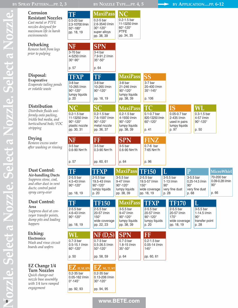
DistributionDistribute fluids uni‑formly onto packing,trickle bed media, andhorticultural beds; VOCstripping
Dust Control: Air‑handling DuctsSuppress stone, coal,and other dust in ventducts; control paintspray carry‑over
Dust Control: AreaSuppress dust at con‑veyor transfer points,dump pits and loadinghoppers
Etching:ElectronicsWash and rinse circuitboards and wafers
EZ Change 1/4Turn NozzlesQuick change‑out nozzle base assemblywith 1/4 turn rampedengagement
0.7-3 bar0.5-15.1 l/min60°-120°
p. 50
WL0.7-3 bar1.8-15 l/min35°-50°
p. 64
SPN0.2-1.5 bar0.05-14 l/min145°
pp. 60, 61
FF
0.2-35 bar0.05-162 l/min0°-145°
pp. 92, 93
EZ FF, NF, SPN0.2-35 bar0.13-206 l/min30°-120°
pp. 94, 95
EZ WL, TF, WT
0.7-3 bar0.5-26.5 l/min50°-120°
pp. 58, 59
NF (D,S)
3-8 bar10-265 l/min90°-120°lumpy liquidsp. 20
TFXP3-8 bar10-265 l/min90°-120°
pp. 18, 19
TF3-8 bar21-246 l/min90°-120°lumpy liquidspp. 38, 39
MaxiPassDisposal: EvaporativeEvaporate tailing pondsor volatile waste
DryingRemove excess waterafter washing or rinsing 3-5 bar
0.6-90 Nm3/h
p. 57
NF3-5 bar0.3-90 Nm3/h
pp. 60, 61
FF3-5 bar0.6-90 Nm3/h
p. 64
SPN0.7-6 bar7-65 Nm3/h
p. 96
FINZ
DebarkingRemove bark from logsprior to pulping 3-70 bar
4-5250 l/min30°-90°
p. 57
NF3-4 bar7.9-91.2 l/min35°-50°
p. 64
SPN
CorrosionResistant NozzlesCast metal or PTFE nozzles designed formaximum life in harshenvironments
0.5-20 bar2.3-10700 l/min50°-180°pp. 18, 19
TF0.2-5 bar2.6-3540 l/min30°-120°super alloyspp. 38, 39
MaxiPass0.2-1.5 bar11-13250 l/min60°-120°PTFEpp. 34, 35
NC
70-200 bar0.09-0.28 l/min90°
p. 66
MicroWhirl
www.BETE.com
BY SPRAY PATTERN....PP. 2, 3 BY NOZZLE TYPE....PP. 4, 5 BY APPLICATION....PP. 6‑12
3-7 bar20-400 l/min35°-145°
p. 106
SS
Select a Nozzle. Select a N
ozzle. Select a Nozzle. Select a
0.2-1 bar6-435 l/min90°-120°lumpy liquidspp. 38, 39
MaxiPass
0.7-5 bar0.1-18.3 l/min145°
pp. 60, 61
FF
0.4-1.5 bar11-53 l/min90°-120°
p. 50
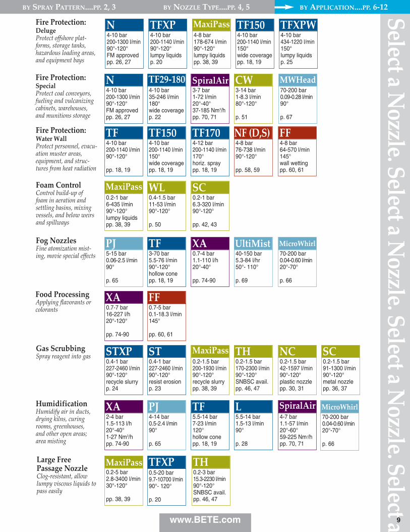
WLFoam ControlControl build‑up offoam in aeration andsettling basins, mixingvessels, and below weirsand spillways
2-4 bar1.5-113 l/h20°-40°1-27 Nm3/hpp. 74-90
XA
0.7-7 bar16-227 l/h20°-120°
pp. 74-90
XA
5-15 bar0.06-2.5 l/min90°
p. 65
PJ
0.4-1 bar227-2460 l/min90°-120°recycle slurryp. 24
STXP0.4-1 bar227-2460 l/min90°-120°resist erosionp. 23
ST0.2-1.5 bar200-1930 l/min90°-120°recycle slurrypp. 38, 39
MaxiPass
0.2-5 bar2.8-3400 l/min30°-120°
pp. 38, 39
MaxiPass
0.2-1.5 bar170-2300 l/min90°-120°SNBSC avail.pp. 46, 47
TH0.2-1.5 bar42-1597 l/min90°-120°plastic nozzlepp. 30, 31
NC0.2-1.5 bar91-1300 l/min90°-120°metal nozzlepp. 36, 37
SC
4-14 bar0.5-2.4 l/min90°
p. 65
PJ5.5-14 bar7-23 l/min120°hollow conepp. 18, 19
TF
0.5-20 bar9.7-10700 l/min90°- 120°
p. 20
TFXP
3-70 bar5.5-76 l/min90°-120°hollow conepp. 18, 19
TF
5.5-14 bar1.5-13 l/min90°
p. 28
L4-7 bar1.1-57 l/min20°-60°59-225 Nm3/hpp. 70, 71
SpiralAirHumidificationHumidify air in ducts,drying kilns, curingrooms, greenhouses,and other open areas;area misting
Large FreePassage NozzleClog‑resistant, allowlumpy viscous liquids topass easily
Fog NozzlesFine atomization mist‑ing, movie special effects
Food ProcessingApplying flavorants orcolorants
Gas ScrubbingSpray reagent into gas
4-10 bar200-1300 l/min90°-120°FM approvedpp. 26, 27
N
4-10 bar200-1140 l/min90°-120°
pp. 18, 19
TF
4-10 bar35-246 l/min180°wide coveragep. 22
TF29‑180
4-10 bar200-1140 l/min150°wide coveragepp. 18, 19
TF150
3-7 bar1-72 l/min20°-40°37-185 Nm3/hpp. 70, 71
SpiralAir
4-12 bar200-1140 l/min170°horiz. spraypp. 18, 19
TF170
3-14 bar1-8.3 l/min80°-120°
p. 51
CW
4-8 bar64-570 l/min145°wall wettingpp. 60, 61
FF
Fire Protection: SpecialProtect coal conveyors,fueling and vulcanizingcabinets, warehouses,and munitions storage
Fire Protection: Water WallProtect personnel, evacu‑ation muster areas,equipment, and struc‑tures from heat radiation
4-8 bar76-738 l/min90°-120°
pp. 58, 59
NF (D,S)
0.2-1 bar6.3-320 l/min90°-120°
pp. 42, 43
SC
0.7-4 bar1.1-110 l/h20°-40°
pp. 74-90
XA40-150 bar5.3-84 l/hr50°- 110°
p. 69
UltiMist
9
70-200 bar0.04-0.60 l/min20°-70°
p. 66
MicroWhirl
4-10 bar200-1140 l/min90°-120°lumpy liquidsp. 20
TFXP4-10 bar200-1300 l/min90°-120°FM approvedpp. 26, 27
N4-8 bar178-674 l/min90°-120°lumpy liquidspp. 38, 39
MaxiPass4-10 bar200-1140 l/min150°wide coveragepp. 18, 19
TF150Fire Protection:DelugeProtect offshore plat‑forms, storage tanks,hazardous loading areas,and equipment bays
4-10 bar434-1220 l/min150°lumpy liquidsp. 25
TFXPW
70-200 bar0.09-0.28 l/min90°
p. 67
MWHead
70-200 bar0.04-0.60 l/min20°-70°
p. 66
MicroWhirl
www.BETE.com
BY SPRAY PATTERN....PP. 2, 3 BY NOZZLE TYPE....PP. 4, 5 BY APPLICATION....PP. 6‑12
0.2-3 bar15.3-2230 l/min90°-120°SNBSC avail.pp. 46, 47
TH
Noz
zle.
Sele
ct a N
ozzl
e. Se
lect
a Noz
zle.
Sele
ct a N
ozzl
e.
15-150 bar1.8-17 l/hr60°- 110°
p. 69
UltiMist
0.7-7 bar40-1000 l/min
p. 105
TurboMix
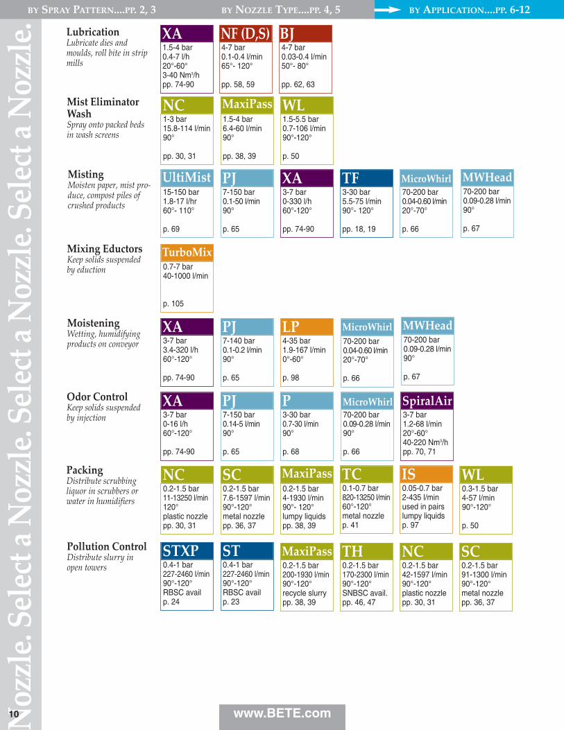
MistingMoisten paper, mist pro‑duce, compost piles ofcrushed products
Mixing EductorsKeep solids suspendedby eduction
MoisteningWetting, humidifyingproducts on conveyor
Odor ControlKeep solids suspendedby injection
PackingDistribute scrubbingliquor in scrubbers orwater in humidifiers
Pollution ControlDistribute slurry inopen towers
3-7 bar0-16 l/h60°-120°
pp. 74-90
XA
3-7 bar3.4-320 l/h60°-120°
pp. 74-90
XA
7-150 bar0.14-5 l/min90°
p. 65
PJ
7-140 bar0.1-0.2 l/min90°
p. 65
PJ
3-7 bar0-330 l/h60°-120°
pp. 74-90
XA7-150 bar0.1-50 l/min90°
p. 65
PJ3-30 bar5.5-75 l/min90°- 120°
pp. 18, 19
TF
3-30 bar0.7-30 l/min90°
p. 68
P
Mist EliminatorWashSpray onto packed bedsin wash screens
1-3 bar15.8-114 l/min90°
pp. 30, 31
NC1.5-4 bar6.4-60 l/min90°
pp. 38, 39
MaxiPass1.5-5.5 bar0.7-106 l/min90°-120°
p. 50
WL
0.2-1.5 bar11-13250 l/min120° plastic nozzlepp. 30, 31
NC0.2-1.5 bar4-1930 l/min90°- 120°lumpy liquidspp. 38, 39
MaxiPass0.3-1.5 bar4-57 l/min90°-120°
p. 50
WL0.2-1.5 bar7.6-1597 l/min90°-120°metal nozzlepp. 36, 37
SC0.1-0.7 bar820-13250 l/min60°-120°metal nozzlep. 41
TC0.05-0.7 bar2-435 l/minused in pairslumpy liquidsp. 97
IS
4-35 bar1.9-167 l/min0°-60°
p. 98
LP
10
0.4-1 bar227-2460 l/min90°-120°RBSC availp. 24
STXP0.4-1 bar227-2460 l/min90°-120°RBSC availp. 23
ST0.2-1.5 bar200-1930 l/min90°-120°recycle slurrypp. 38, 39
MaxiPass0.2-1.5 bar170-2300 l/min90°-120°SNBSC avail.pp. 46, 47
TH0.2-1.5 bar42-1597 l/min90°-120°plastic nozzlepp. 30, 31
NC0.2-1.5 bar91-1300 l/min90°-120°metal nozzlepp. 36, 37
SC
70-200 bar0.04-0.60 l/min20°-70°
p. 66
MicroWhirl
70-200 bar0.04-0.60 l/min20°-70°
p. 66
MicroWhirl
70-200 bar0.09-0.28 l/min90°
p. 66
MicroWhirl3-7 bar1.2-68 l/min20°-60°40-220 Nm3/hpp. 70, 71
SpiralAir
1.5-4 bar0.4-7 l/h20°-60°3-40 Nm3/hpp. 74-90
XALubricationLubricate dies andmoulds, roll bite in stripmills
4-7 bar0.1-0.4 l/min65°- 120°
pp. 58, 59
NF (D,S)4-7 bar0.03-0.4 l/min50°- 80°
pp. 62, 63
BJ
70-200 bar0.09-0.28 l/min90°
p. 67
MWHead
70-200 bar0.09-0.28 l/min90°
p. 67
MWHead
www.BETE.com
BY SPRAY PATTERN....PP. 2, 3 BY NOZZLE TYPE....PP. 4, 5 BY APPLICATION....PP. 6‑12
Select a Nozzle. Select a N
ozzle. Select a Nozzle. Select a
3.5-7 bar5.3-57 l/min20°-60°45-225 Nm3/hpp. 70, 71
SpiralAir
15-350 bar35.3-5970 l/h50°- 80°
pp. 54, 55
Twist & Dry
3-4 bar2.6-167 l/h20°-40°1.8-27 Nm3/hpp. 74-90
XA
15-350 bar11.3-469 l/h70°-75°
p. 56
TDL
4-10 bar0.45-57 l/min80°-130°
pp. 42, 43
WT
4-35 bar1.9-167 l/min30°- 60°
p. 98
LP
1.7-7 bar8.3-74 l/min145°wide coveragepp. 60, 61
FF
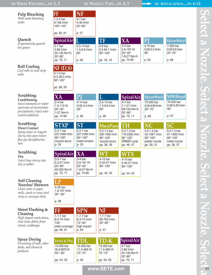
Scrubbing: DryInject lime slurry intodry scrubber
Self CleaningNozzles/ ShowersClean webs in papermills, wash or rinse steelstrip or conveyor belts
Street Flushing &CleaningHigh impact wash down,clear loose debris fromstreets, walkways
Spray DryingProcessing of milk, otherfoods, and chemicalproducts
1.7-7 bar8.3-74 l/min15°-50°high impactp. 64
SPN1.7-7 bar85-763 l/min50°-90°
p. 57
NF
5.5-14 bar1.5-6.8 l/min90°
p. 28
L3-8 bar5.5-84.1 l/min90°-120°
pp. 18, 19
TF
Scrubbing:Direct ContactSpray water or reagentslurry into open tower;flue gas desulphuriza‑tion
2-4 bar1.5-113 l/h20°-40°1-27 Nm3/hpp. 74-90
XA4-14 bar0.05-2.4 l/min90°
p. 65
PJ5.5-14 bar1.5-6.8 l/min90°
p. 28
L4-7 bar1.1-57 l/min59-150 Nm3/h20°-60°pp. 70, 71
SpiralAir
2-7 bar2-80 l/min45-139 Nm3/h20°-90°pp. 70, 71
SpiralAir
Scrubbing:ConditioningInject ammonia or waterupstream of electrostaticprecipitators; inject odorcontrol additives
QuenchEvaporatively quenchhot gasses
Roll CoolingCool rolls in steel stripmills 0.7-3 bar
0.5-26.5 l/min60°-120°
pp. 58, 59
NF (D,S)
2-7 bar2-80 l/min25-135 Nm3/h20°-90°pp. 70, 71
SpiralAir
11
0.4-1 bar227-2460 l/min90°-120°recycle slurryp. 24
STXP0.4-1 bar227-2460 l/min90°-120°resist erosionp. 23
ST0.2-1.5 bar200-1930 l/min90°-120°recycle slurrypp. 38, 39
MaxiPass0.2-1.5 bar170-2300 l/min90°-120°SNBSC avail.pp. 46, 47
TH0.2-1.5 bar42-1597 l/min90°-120°plastic nozzlepp. 30, 31
NC0.2-1.5 bar91-1300 l/min90°-120°metal nozzlepp. 36, 37
SC
Pulp BleachingWall wash bleachingtanks
1.5-4 bar0-196 l/min105°-145°
pp. 60, 61
FF3-7 bar4-36 l/min20°-60°
p. 57
NF
70-200 bar0.04-0.60 l/min20°-70°
p. 66
MicroWhirl70-200 bar0.09-0.28 l/min90°
p. 67
MWHead
4-10 bar0.45-57 l/min80°-130°
pp. 44, 45
WTX
15-350 bar11.3-469 l/h70°-75°
pp. 54, 55
TD‑K
www.BETE.com
BY SPRAY PATTERN....PP. 2, 3 BY NOZZLE TYPE....PP. 4, 5 BY APPLICATION....PP. 6‑12
3-4 bar2.6-167 l/h20°-40°1.8-27 Nm3/hpp. 74-90
XA4-70 bar0.03-5.3 l/min90°
p. 65
PJ7-200 bar0.03-0.6 l/min20°-70°
p. 66
MicroWhirl
Noz
zle.
Sele
ct a N
ozzl
e. Se
lect
a Noz
zle.
Sele
ct a N
ozzl
e.
0.7-5.5 bar11-273 l/min210°very compactp. 99
TW0.7-5.5 bar11-511 l/min150°wide coveragepp. 18, 19
TF1500.7-3 bar29-224 l/min360°lumpy liquidsp. 40
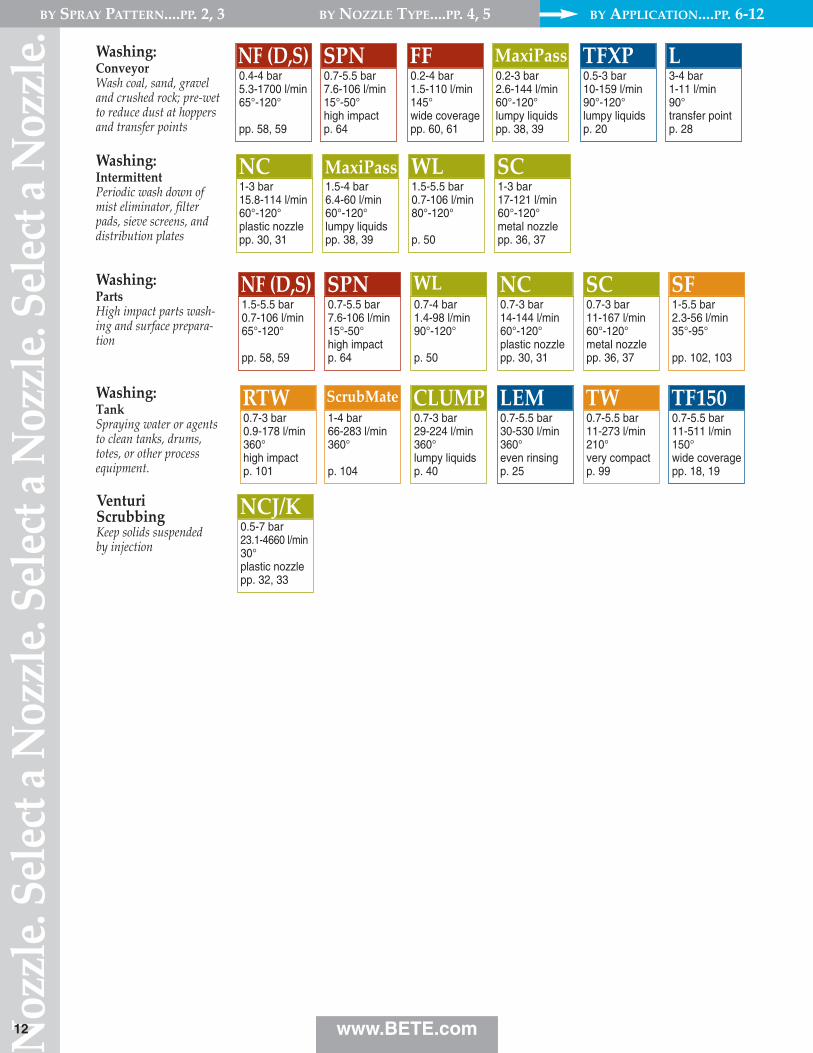
CLUMPWashing: TankSpraying water or agentsto clean tanks, drums,totes, or other processequipment.
0.7-5.5 bar30-530 l/min360°even rinsingp. 25
LEM0.7-3 bar0.9-178 l/min360°high impactp. 101
RTW
1-5.5 bar2.3-56 l/min35°-95°
pp. 102, 103
SF
1-4 bar66-283 l/min360°
p. 104
ScrubMate
0.7-4 bar1.4-98 l/min90°-120°
p. 50
WL0.7-3 bar14-144 l/min60°-120°plastic nozzlepp. 30, 31
NC0.7-3 bar11-167 l/min60°-120°metal nozzlepp. 36, 37
SCWashing:PartsHigh impact parts wash‑ing and surface prepara‑tion
0.7-5.5 bar7.6-106 l/min15°-50°high impactp. 64
SPN1.5-5.5 bar0.7-106 l/min65°-120°
pp. 58, 59
NF (D,S)
1.5-4 bar6.4-60 l/min60°-120°lumpy liquidspp. 38, 39
MaxiPass1-3 bar15.8-114 l/min60°-120°plastic nozzlepp. 30, 31
NC1.5-5.5 bar0.7-106 l/min80°-120°
p. 50
WL1-3 bar17-121 l/min60°-120°metal nozzlepp. 36, 37
SCWashing:IntermittentPeriodic wash down ofmist eliminator, filterpads, sieve screens, anddistribution plates
12
0.5-3 bar10-159 l/min90°-120°lumpy liquidsp. 20
TFXP0.2-3 bar2.6-144 l/min60°-120°lumpy liquidspp. 38, 39
MaxiPass0.2-4 bar1.5-110 l/min145°wide coveragepp. 60, 61
FF3-4 bar1-11 l/min90°transfer pointp. 28
LWashing:ConveyorWash coal, sand, graveland crushed rock; pre‑wetto reduce dust at hoppersand transfer points
0.7-5.5 bar7.6-106 l/min15°-50°high impactp. 64
SPN0.4-4 bar5.3-1700 l/min65°-120°
pp. 58, 59
NF (D,S)
0.5-7 bar23.1-4660 l/min30°plastic nozzlepp. 32, 33
NCJ/KVenturiScrubbingKeep solids suspendedby injection
www.BETE.com
BY SPRAY PATTERN....PP. 2, 3 BY NOZZLE TYPE....PP. 4, 5 BY APPLICATION....PP. 6‑12
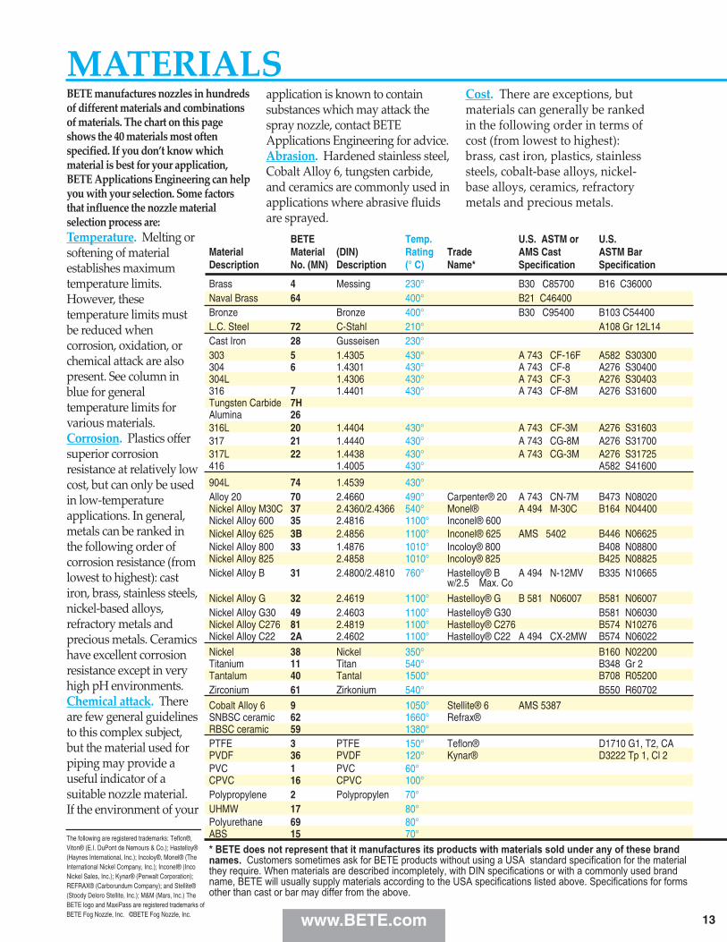
BETE manufactures nozzles in hundredsof different materials and combinationsof materials. The chart on this pageshows the 40 materials most oftenspecified. If you don’t know whichmaterial is best for your application,BETE Applications Engineering can helpyou with your selection. Some factorsthat influence the nozzle materialselection process are:Temperature. Melting orsoftening of materialestablishes maximumtemperature limits.However, thesetemperature limits mustbe reduced whencorrosion, oxidation, orchemical attack are alsopresent. See column inblue for generaltemperature limits forvarious materials.Corrosion. Plastics offersuperior corrosionresistance at relatively lowcost, but can only be usedin low‑temperatureapplications. In general,metals can be ranked inthe following order ofcorrosion resistance (fromlowest to highest): castiron, brass, stainless steels,nickel‑based alloys,refractory metals andprecious metals. Ceramicshave excellent corrosionresistance except in veryhigh pH environments.Chemical attack. Thereare few general guidelinesto this complex subject,but the material used forpiping may provide auseful indicator of asuitable nozzle material. If the environment of your
application is known to containsubstances which may attack thespray nozzle, contact BETEApplications Engineering for advice.Abrasion. Hardened stainless steel,Cobalt Alloy 6, tungsten carbide,and ceramics are commonly used inapplications where abrasive fluidsare sprayed.
Cost. There are exceptions, but materials can generally be rankedin the following order in terms ofcost (from lowest to highest):brass, cast iron, plastics, stainlesssteels, cobalt‑base alloys, nickel‑base alloys, ceramics, refractorymetals and precious metals.
MATERIALS
The following are registered trademarks: Teflon®,Viton® (E.I. DuPont de Nemours & Co.); Hastelloy®(Haynes International, Inc.); Incoloy®, Monel® (TheInternational Nickel Company, Inc.); Inconel® (IncoNickel Sales, Inc.); Kynar® (Penwalt Corporation);REFRAX® (Carborundum Company); and Stellite®(Stoody Deloro Stellite, Inc.); M&M (Mars, Inc.) TheBETE logo and MaxiPass are registered trademarks ofBETE Fog Nozzle, Inc. ©BETE Fog Nozzle, Inc.
BETE Temp. U.S. ASTM or U.S. Material Material (DIN) Rating Trade AMS Cast ASTM Bar Description No. (MN) Description (° C) Name* Specification Specification
Brass 4 Messing 230° B30 C85700 B16 C36000Naval Brass 64 400° B21 C46400Bronze Bronze 400° B30 C95400 B103 C54400L.C. Steel 72 C-Stahl 210° A108 Gr 12L14Cast Iron 28 Gusseisen 230°303 5 1.4305 430° A 743 CF-16F A582 S30300304 6 1.4301 430° A 743 CF-8 A276 S30400304L 1.4306 430° A 743 CF-3 A276 S30403316 7 1.4401 430° A 743 CF-8M A276 S31600Tungsten Carbide 7HAlumina 26316L 20 1.4404 430° A 743 CF-3M A276 S31603317 21 1.4440 430° A 743 CG-8M A276 S31700317L 22 1.4438 430° A 743 CG-3M A276 S31725416 1.4005 430° A582 S41600
904L 74 1.4539 430°Alloy 20 70 2.4660 490° Carpenter® 20 A 743 CN-7M B473 N08020Nickel Alloy M30C 37 2.4360/2.4366 540° Monel® A 494 M-30C B164 N04400Nickel Alloy 600 35 2.4816 1100° Inconel® 600Nickel Alloy 625 3B 2.4856 1100° Inconel® 625 AMS 5402 B446 N06625Nickel Alloy 800 33 1.4876 1010° Incoloy® 800 B408 N08800Nickel Alloy 825 2.4858 1010° Incoloy® 825 B425 N08825Nickel Alloy B 31 2.4800/2.4810 760° Hastelloy® B A 494 N-12MV B335 N10665
w/2.5 Max. CoNickel Alloy G 32 2.4619 1100° Hastelloy® G B 581 N06007 B581 N06007Nickel Alloy G30 49 2.4603 1100° Hastelloy® G30 B581 N06030Nickel Alloy C276 81 2.4819 1100° Hastelloy® C276 B574 N10276Nickel Alloy C22 2A 2.4602 1100° Hastelloy® C22 A 494 CX-2MW B574 N06022Nickel 38 Nickel 350° B160 N02200Titanium 11 Titan 540° B348 Gr 2Tantalum 40 Tantal 1500° B708 R05200Zirconium 61 Zirkonium 540° B550 R60702Cobalt Alloy 6 9 1050° Stellite® 6 AMS 5387SNBSC ceramic 62 1660° Refrax®RBSC ceramic 59 1380°PTFE 3 PTFE 150° Teflon® D1710 G1, T2, CA PVDF 36 PVDF 120° Kynar® D3222 Tp 1, Cl 2 PVC 1 PVC 60°CPVC 16 CPVC 100°Polypropylene 2 Polypropylen 70°UHMW 17 80°Polyurethane 69 80°ABS 15 70°* BETE does not represent that it manufactures its products with materials sold under any of these brandnames. Customers sometimes ask for BETE products without using a USA standard specification for the materialthey require. When materials are described incompletely, with DIN specifications or with a commonly used brandname, BETE will usually supply materials according to the USA specifications listed above. Specifications for formsother than cast or bar may differ from the above.
13www.BETE.com
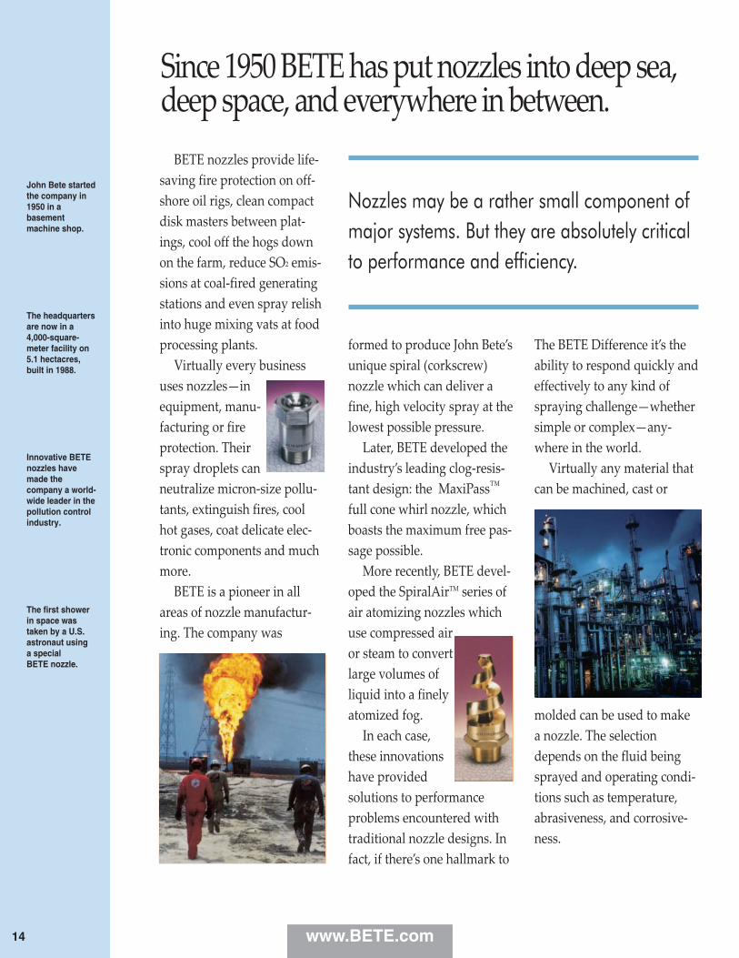
Since 1950 BETE has put nozzles into deep sea,deep space, and everywhere in between.
John Bete startedthe company in1950 in a basementmachine shop.
The headquartersare now in a4,000-square-meter facility on 5.1 hectacres, built in 1988.
Innovative BETEnozzles havemade the com pany a world-wide leader in the pollution controlindustry.
The first showerin space wastaken by a U.S.astronaut using a special BETE nozzle.
BETE nozzles provide life‑saving fire protection on off‑shore oil rigs, clean compactdisk masters between plat‑ings, cool off the hogs downon the farm, reduce SO2 emis‑sions at coal‑fired generatingstations and even spray relishinto huge mixing vats at foodprocessing plants.
Virtually every businessuses nozzles—inequipment, manu‑facturing or fireprotection. Theirspray droplets canneutralize micron‑size pollu‑tants, extinguish fires, coolhot gases, coat delicate elec‑tronic components and muchmore.
BETE is a pioneer in allareas of nozzle manufactur‑ing. The company was
formed to produce John Bete’sunique spiral (corkscrew)nozzle which can deliver afine, high velocity spray at thelowest possible pressure.
Later, BETE developed theindustry’s leading clog‑resis‑tant design: the MaxiPass™
full cone whirl nozzle, whichboasts the maximum free pas‑sage possible.
More recently, BETE devel‑oped the SpiralAirTM series ofair atomizing nozzles whichuse compressed airor steam to convertlarge volumes ofliquid into a finelyatomized fog.
In each case,these innovationshave providedsolutions to performanceproblems encountered withtraditional nozzle designs. Infact, if there’s one hallmark to
The BETE Difference it’s theability to respond quickly andeffectively to any kind ofspraying challenge—whethersimple or complex—any‑where in the world.
Virtually any material thatcan be machined, cast or
molded can be used to makea nozzle. The selectiondepends on the fluid beingsprayed and operating condi‑tions such as temperature,abrasiveness, and corrosive‑ness.
Nozzles may be a rather small component ofmajor systems. But they are absolutely criticalto performance and efficiency.
www.BETE.com14
BETE is the only nozzle manufacturer with acomplete in‑house investment casting foundry.
It takes eight min-utes to heat 12.2kg of stainlesssteel to the1600°C re quiredfor casting.
BETE pioneeredthe use of manynozzle materialsincluding PTFEand titanium.
Platinum is themost expensivematerial the com-pany has everused; every scrapwas saved.
Traditional NewEngland craft-manship in astate-of-the-artmanufacturingfacility.
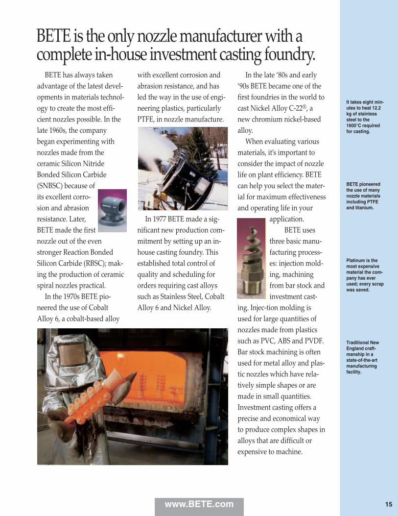
BETE has always takenadvantage of the latest devel‑opments in materials technol‑ogy to create the most effi‑cient nozzles possible. In thelate 1960s, the companybegan experimenting withnozzles made from theceramic Silicon NitrideBonded Silicon Carbide(SNBSC) because ofits excellent corro‑sion and abrasionresistance. Later,BETE made the firstnozzle out of the evenstronger Reaction BondedSilicon Carbide (RBSC); mak‑ing the production of ceramicspiral nozzles practical.
In the 1970s BETE pio‑neered the use of CobaltAlloy 6, a cobalt‑based alloy
with excellent corrosion andabrasion re sistance, and hasled the way in the use of engi‑neering plastics, particularlyPTFE, in nozzle manufacture.
In 1977 BETE made a sig‑nificant new production com‑mitment by setting up an in‑house casting foundry. Thisestablished total control ofquality and scheduling fororders requiring cast alloyssuch as Stainless Steel, CobaltAlloy 6 and Nickel Alloy.
In the late ‘80s and early‘90s BETE became one of thefirst foundries in the world tocast Nickel Alloy C‑22®, anew chromium nickel‑basedalloy.
When evaluating variousmaterials, it’s important toconsider the impact of nozzlelife on plant efficiency. BETEcan help you select the mater‑ial for maximum effectivenessand op erating life in your
application. BETE uses
three basic manu‑facturing process‑es: injection mold‑ing, machiningfrom bar stock andinvestment cast‑
ing. Injec‑tion molding isused for large quantities ofnozzles made from plasticssuch as PVC, ABS and PVDF.Bar stock machining is oftenused for metal alloy and plas‑tic nozzles which have rela‑tively simple shapes or aremade in small quantities.Investment casting offers aprecise and economical wayto produce complex shapes inalloys that are difficult orexpensive to machine.
www.BETE.com 15
BETE can perform every procedure in‑house –from casting to machining to assembly.
BETE also doescontract testingof nozzles andspray systems formany customers.
Complete in-house design andmanufacturingmean on-timedelivery.
A small change in a droplet’ssize, shape, orspeed can have a major impact on perform ance.
When testingnozzles wherefar=reachingspray is critical,the 9 meterremovable laboratory wall is opened
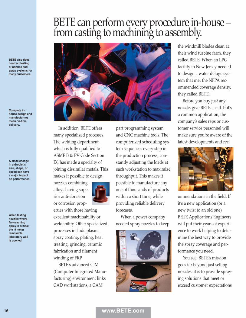
In addition, BETE offersmany specialized processes.The welding department,which is fully qualified toASME B & PV Code SectionIX, has made a specialty ofjoining dissimilar metals. Thismakes it possible to designnozzles combiningalloys having supe‑rior anti‑abrasionor corrosion prop‑erties with those havingexcellent machinability orweldability. Other specializedprocesses include plasmaspray coating, plating, heattreating, grinding, ceramicfabrication and filamentwinding of FRP.
BETE’s advanced CIM(Computer Integrated Manu‑facturing) environment linksCAD workstations, a CAM
part programming systemand CNC machine tools. Thecomputerized scheduling sys‑tem sequences every step inthe production process, con‑stantly adjusting the loads ateach workstation to maximizethroughput. This makes itpossible to manufacture anyone of thousands of productswithin a short time, whileproviding reliable deliveryforecasts.
When a power companyneeded spray nozzles to keep
the windmill blades clean attheir wind turbine farm, theycalled BETE. When an LPGfacility in New Jersey neededto design a water deluge sys‑tem that met the NFPA rec‑ommended coverage density,they called BETE.
Before you buy just anynozzle, give BETE a call. If it’sa common application, thecompany’s sales reps or cus‑tomer service personnel willmake sure you’re aware of thelatest developments and rec‑
ommendations in the field. Ifit’s a new application (or anew twist to an old one)BETE Applications Engineerswill put their years of experi‑ence to work helping to deter‑mine the best way to providethe spray coverage and per‑formance you need.
You see, BETE’s missiongoes far beyond just sellingnozzles: it is to provide spray‑ing solutions that meet orexceed customer expectations
www.BETE.com16

BETE is well known for its ability to find creativesolutions to difficult spraying challenges.
BETE ApplicationEngineersprovide effectivesolutions tothousands ofnozzle requestsevery year.
The Spiral TFXPand MaxiPassTM
are the industry’s two leading clog-resistantdesigns.
Computer terminalsthroughout theplant keep trackof thestatus of yourorder.
in every detail. Extensive in‑house capabilities—fromCAD design through patterntesting—make it possible tooffer the highest level of qual‑ity control throughout everyphase of production whileproviding the most respon‑sive customer service in theindustry.
A nozzle’s effectiveness isbased on the size, shape,velocity and distribution of itsdroplets.
The goal of the BETE test‑ing laboratory is to find newways to helpcustomersmaximizeperformancewhile usingless liquid and lower pump‑ing pressure.
BETE’s computer modelingoptimizes nozzle selection bytaking into consideration theeffects of gravity, fluid pres‑sure, gas velocity and dis‑tance on spray coverage.
BETE’s advanced, comput‑erized Droplet Analyzer canmeasure in‑spray dropletsfrom 2.5 to over 15,000microns at high velocities.The spray images are illumi‑nated by a strobe, displayed
on a monitor, analyzed, andstored—all in less than one‑tenth of a second. Sincedroplet size has become socritical for many engineered
applications, the BETEDroplet Analyzer is oftenused from the prototype stagethrough final manufacture tomake sure the design meetsspecifications.
Liquid distribution is justas critical to system designand overall nozzle effective‑
ness. BETE's high‑speed“Patternator” providesdetailed information on spraydensity and coverage at vari‑ous locations in the spray
area and is totally integratedwith the Droplet Analyzer,permitting complete and pre‑
cise mea‑surementof sprayperfor‑mance.
Whetheryou’re
working on a new applicationor a modification, BETE’s labcan quickly evaluate yourrequirements and develop aneffective solution.
www.BETE.com 17
SP
IRA
LTO
OR
DER
:spe
cify
pip
e si
ze, c
onne
ctio
n ty
pe,
nozz
le n
umbe
r, sp
ray
angl
e, a
nd m
ater
ial.
18
TF
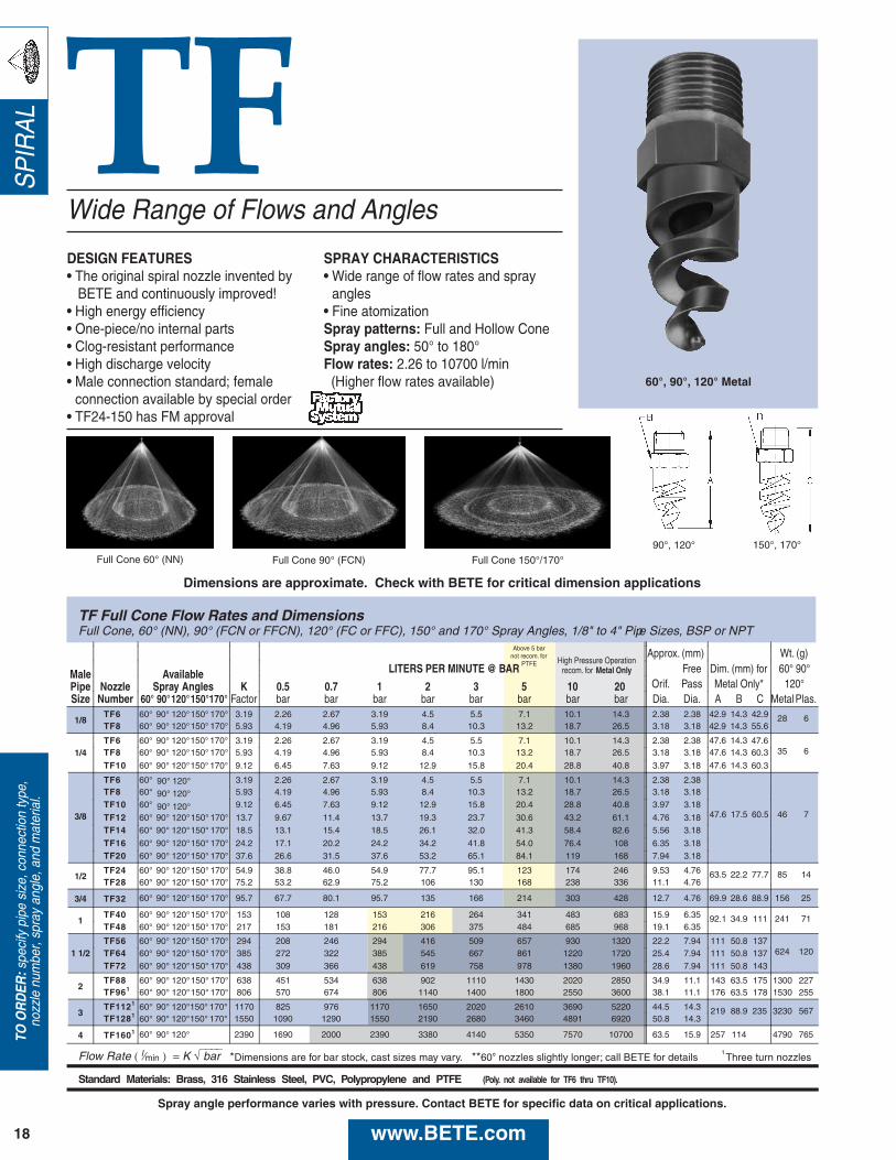
TF Full Cone Flow Rates and DimensionsFull Cone, 60° (NN), 90° (FCN or FFCN), 120° (FC or FFC), 150° and 170° Spray Angles, 1/8" to 4" Pipe Sizes, BSP or NPT
High Pressure OperationApprox. (mm) Wt. (g)
Male Available LITERS PER MINUTE @ BAR recom. for Metal Only Free Dim. (mm) for 60° 90°
Pipe Nozzle Spray Angles K 0.5 0.7 1 2 3 5 10 20 Orif. Pass Metal Only* 120°Size Number 60° 90°120°150°170° Factor bar bar bar bar bar bar bar bar Dia. Dia. A B C Metal Plas.
1/8TF6 60° 90° 120° 3.19 2.26 2.67 3.19 4.5 5.5 7.1 10.1 14.3 2.38 2.38 42.9 14.3 28 6TF8 60° 90° 120° 5.93 4.19 4.96 5.93 8.4 10.3 13.2 18.7 26.5 3.18 3.18
1/4TF6 60° 90° 120° 3.19 2.26 2.67 3.19 4.5 5.5 7.1 10.1 14.3 2.38 2.38 47.6 14.3
35 6TF8 60° 90° 120° 5.93 4.19 4.96 5.93 8.4 10.3 13.2 18.7 26.5 3.18 3.18
TF10 60° 90° 120° 9.12 6.45 7.63 9.12 12.9 15.8 20.4 28.8 40.8 3.97 3.18
3/8
TF6 60° 3.19 2.26 2.67 3.19 4.5 5.5 7.1 10.1 14.3 2.38 2.38
47.6 17.5 60.5 46 7
TF8 60° 5.93 4.19 4.96 5.93 8.4 10.3 13.2 18.7 26.5 3.18 3.18TF10 60° 9.12 6.45 7.63 9.12 12.9 15.8 20.4 28.8 40.8 3.97 3.18
TF12 60° 90° 120°150° 170° 13.7 9.67 11.4 13.7 19.3 23.7 30.6 43.2 61.1 4.76 3.18TF14 60° 90° 120°150° 170° 18.5 13.1 15.4 18.5 26.1 32.0 41.3 58.4 82.6 5.56 3.18
TF16 60° 90° 120°150° 170° 24.2 17.1 20.2 24.2 34.2 41.8 54.0 76.4 108 6.35 3.18TF20 60° 90° 120°150° 170° 37.6 26.6 31.5 37.6 53.2 65.1 84.1 119 168 7.94 3.18
1/2TF24 60° 90° 120°150° 170° 54.9 38.8 46.0 54.9 77.7 95.1 123 174 246 9.53 4.76 63.5 22.2 77.7 85 14TF28 60° 90° 120°150° 170° 75.2 53.2 62.9 75.2 106 130 168 238 336 11.1 4.76
3/4 TF32 60° 90° 120°150° 170° 95.7 67.7 80.1 95.7 135 166 214 303 428 12.7 4.76 69.9 28.6 88.9 156 25
1TF40 60° 90° 120°150° 170° 153 108 128 153 216 264 341 483 683 15.9 6.35 92.1 34.9 111 241 71TF48 60° 90° 120°150° 170° 217 153 181 216 306 375 484 685 968 19.1 6.35
1 1/2TF56 60° 90° 120°150° 170° 294 208 246 294 416 509 657 930 1320 22.2 7.94 111 50.8 137
624 120TF64 60° 90° 120°150° 170° 385 272 322 385 545 667 861 1220 1720 25.4 7.94 111 50.8 137TF72 60° 90° 120°150° 170° 438 309 366 438 619 758 978 1380 1960 28.6 7.94 111 50.8 143
2TF88 90° 120°150° 170° 638 451 534 638 902 1110 1430 2020 2850 34.9 11.1 143 63.5 175 1300 227TF961 90° 120°150° 170° 806 570 674 806 1140 1400 1800 2550 3600 38.1 11.1 176 63.5 178 1530 255
3TF1121 90° 120° 1170 825 976 1170 1650 2020 2610 3690 5220 44.5 14.3 219 88.9 3230 567TF1281 90° 120° 1550 1090 1290 1550 2190 2680 3460 4891 6920 50.8 14.3
4 TF1601 90° 120° 2390 1690 2000 2390 3380 4140 5350 7570 10700 63.5 15.9 257 114 4790 765
Flow Rate ( l⁄min ) = K √⎯⎯⎯⎯ bar *Dimensions are for bar stock, cast sizes may vary. 1 Three turn nozzles
Standard Materials: Brass, 316 Stainless Steel, PVC, Polypropylene and PTFE (Poly. not available for TF6 thru TF10).
Above 5 barnot recom. for
PTFE
150° 170°
150° 170°150° 170°
150° 170°150° 170°
60°60°
60°60°
60°
42.942.9 14.3 55.6
47.647.6 14.3 60.3
47.6 14.3 60.3
150° 170°150° 170°
90° 120°90° 120°
90° 120°
235
**60° nozzles slightly longer; call BETE for details
Wide Range of Flows and Angles
DESIGN FEATURES• The original spiral nozzle invented by
BETE and continuously improved!• High energy efficiency• One-piece/no internal parts• Clog-resistant performance• High discharge velocity• Male connection standard; female
connection available by special order• TF24-150 has FM approval
SPRAY CHARACTERISTICS• Wide range of flow rates and spray
angles• Fine atomizationSpray patterns: Full and Hollow ConeSpray angles: 50° to 180°Flow rates: 2.26 to 10700 l/min(Higher flow rates available)
90°, 120° 150°, 170°
60°, 90°, 120° Metal
Dimensions are approximate. Check with BETE for critical dimension applications
Full Cone 90° (FCN) Full Cone 150°/170° Full Cone 60° (NN)
www.BETE.com
Spray angle performance varies with pressure. Contact BETE for specific data on critical applications.
SP
IRA
L
19
CA
LL 413-772-2166C
all for the name of your nearest B
ET
E representative.
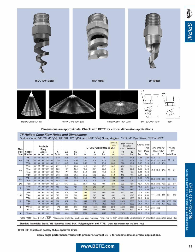
TF Hollow Cone Flow Rates and DimensionsHollow Cone, 50° (N), 60° (V), 90° (M), 120° (W), and 180° (XW) Spray Angles, 1/4" to 4" Pipe Sizes, BSP or NPT
AvailableHigh Pressure
Operation Approx. (mm)
Male Spray LITERS PER MINUTE @ BAR recom. for Metal Only Free Dim. (mm) for Wt. (g)
Pipe Nozzle Angles K 0.5 0.7 1 2 3 5 10 20 Orif. Pass. Metal Only* 180°Size Number 50° 60° 90° 120° 180° Factor bar bar bar bar bar bar bar bar Dia. Dia. A B C Metal Plas.
1/4TF6 50° 60° 90° 120° 3.19 2.26 2.67 3.19 4.5 5.5 7.1 10.1 14.3 2.38 2.38 42.9 14.3
35 21TF8 50° 60° 90° 120° 180° 5.93 4.19 4.96 5.93 8.4 10.3 13.2 18.7 26.5 3.18 3.18 47.6 14.3 47.6
TF10 50° 60° 90° 120° 180° 9.12 6.45 7.63 9.12 12.9 15.8 20.4 28.8 40.8 3.97 3.18 47.6 14.3 47.6
3/8
TF12 50° 60° 90° 120° 180° 13.7 9.7 11.4 13.7 19.3 23.7 30.6 43.2 61.1 4.76 3.18
47.6 17.51 47.6 50 21TF14 50° 60° 90° 120° 180° 18.5 13.1 15.4 18.5 26.1 32.0 41.3 58.4 82.6 5.56 3.18
TF16 50° 60° 90° 120° 180° 24.2 17.1 20.2 24.2 34.2 41.8 54.0 76.4 108 6.35 3.18
TF20 50° 60° 90° 120° 180° 37.6 26.6 31.5 37.6 53.2 65.1 84.1 119 168 7.94 3.18
1/2TF24 50° 60° 90° 120° 180° 54.9 38.8 46.0 54.9 77.7 95.1 123 174 246 9.53 4.76 63.5 22.2 60.5 85 25TF28 50° 60° 90° 120° 180° 75.2 53.2 62.9 75.2 106 130 168 238 336 11.1 4.76
3/4 TF32 50° 60° 90° 120° 180° 95.7 67.7 80.1 95.7 135 166 214 303 428 12.7 4.76 69.9 28.6 76.2 85 28
1TF40 60° 90° 120° 180° 153 108 128 153 216 264 341 483 683 15.9 6.35 34.9 92.2 425 85TF48 60° 90° 120° 180° 217 153 181 216 306 375 484 685 968 19.1 6.35
1 1/2TF56 60° 90° 120° 180° 294 208 246 294 416 509 657 930 1320 22.2 7.94
50.8 111 851 170TF64 60° 90° 120° 180° 385 272 322 385 545 667 861 1220 1720 25.4 7.94
TF72 60° 90° 120° 180° 438 309 366 438 619 758 978 1380 1960 28.6 7.94
2 TF88 60° 90° 120° 180° 638 451 534 638 902 1110 1430 2020 2850 34.9 11.1 143 63.5 127 1300 227TF96 60° 90° 120° 180° 806 570 674 806 1140 1400 1800 2550 3600 38.1 11.1 176 63.5 127 1530 255
3 TF112 60° 90° 120° 1170 825 976 1170 1650 2020 2610 3690 5220 44.5 14.3 219 88.9TF128 60° 90° 120° 1550 1090 1290 1550 2190 2680 3460 4891 6920 50.8 14.3
4 TF160 60° 90° 120° 2390 1690 2000 2390 3380 4140 5350 7570 10700 63.5 15.9 257 114
Flow Rate ( l⁄min ) = K √⎯⎯⎯⎯ bar *Dimensions are for bar stock, cast sizes may vary. 1 25.4 mm for 180°
Standard Materials: Brass, 316 Stainless Steel, PVC, Polypropylene and PTFE (Poly. not available for TF6 thru TF10)
Above 5 barnot recom. for
PTFE
111
92.1
Large plastic Spirals (above 2") should not be operated above 1 bar
Hollow Cone 50° (N) Hollow Cone 120° (W) 50°, 60°, 90°, 120° 180°Hollow Cone 180° (XW)
150°, 170° Metal 180° Metal 50° Metal
TF 24 150° available in Factory Mutual-approved Brass
Dimensions are approximate. Check with BETE for critical dimension applications
www.BETE.com
Spray angle performance varies with pressure. Contact BETE for specific data on critical applications.
SP
IRA
L TFXP
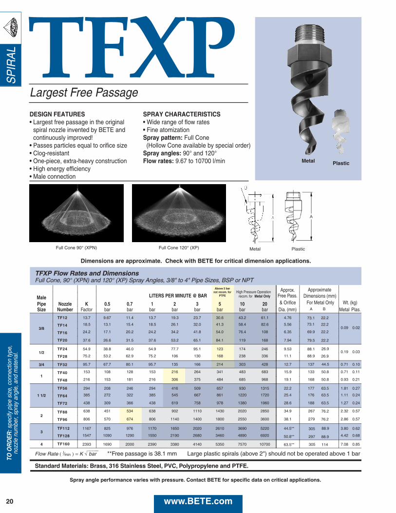
TFXP Flow Rates and DimensionsFull Cone, 90° (XPN) and 120° (XP) Spray Angles, 3/8" to 4" Pipe Sizes, BSP or NPT
High Pressure Operation Approx.
Male LITERS PER MINUTE @ BAR recom. for Metal Only Free Pass.Approximate
Pipe Nozzle K 0.5 0.7 1 2 3 5 10 20 & OrificeDimensions (mm)
Wt. (kg)Size Number Factor bar bar bar bar bar bar bar bar Dia. (mm) A B Metal Plas.
3/8
TF12 13.7 9.67 11.4 13.7 19.3 23.7 30.6 43.2 61.1 4.76
0.09 0.02TF14 18.5 13.1 15.4 18.5 26.1 32.0 41.3 58.4 82.6 5.56
TF16 24.2 17.1 20.2 24.2 34.2 41.8 54.0 76.4 108 6.35
TF20 37.6 26.6 31.5 37.6 53.2 65.1 84.1 119 168 7.94
1/2TF24 54.9 38.8 46.0 54.9 77.7 95.1 123 174 246 9.53
0.19 0.03TF28 75.2 53.2 62.9 75.2 106 130 168 238 336 11.1
3/4 TF32 95.7 67.7 80.1 95.7 135 166 214 303 428 12.7 137 44.5 0.71 0.10
1TF40 153 108 128 153 216 264 341 483 683 15.9 133 50.8 0.71 0.11
TF48 216 153 181 216 306 375 484 685 968 19.1 168 50.8 0.93 0.21
1 1/2
TF56 294 208 246 294 416 509 657 930 1315 22.2 177 63.5 1.81 0.27
TF64 385 272 322 385 545 667 861 1220 1720 25.4 176 63.5 1.11 0.24
TF72 438 309 366 438 619 758 978 1380 1960 28.6 188 63.5 1.27 0.24
2TF88 638 451 534 638 902 1110 1430 2020 2850 34.9 2.32 0.57
TF96 806 570 674 806 1140 1400 1800 2550 3600 38.1 2.86 0.57
3TF112 1167 825 976 1170 1650 2020 2610 3690 5220 44.5** 3.80 0.62
TF128 1547 1090 1290 1550 2190 2680 3460 4890 6920 50.8** 4.42 0.68
4 TF160 2393 1690 2000 2390 3380 4140 5350 7570 10700 63.5** 305 114 7.08 0.85
Flow Rate ( l⁄min ) = K √⎯⎯⎯⎯⎯ bar **Free passage is 38.1 mm
Standard Materials: Brass, 316 Stainless Steel, PVC, Polypropylene and PTFE.
Above 5 barnot recom. for
PTFE
For Metal Only
22.2
22.2
22.2
22.2
73.1
73.1
26.9
26.9
88.1
88.9
76.2
76.2
267
279
88.9
88.9
305
297
69.9
79.5
Large plastic spirals (above 2") should not be operated above 1 bar
Largest Free Passage
DESIGN FEATURES• Largest free passage in the original
spiral nozzle invented by BETE andcontinuously improved!
• Passes particles equal to orifice size• Clog-resistant• One-piece, extra-heavy construction• High energy efficiency• Male connection
SPRAY CHARACTERISTICS• Wide range of flow rates• Fine atomizationSpray pattern: Full Cone(Hollow Cone available by special order)
Spray angles: 90° and 120°Flow rates: 9.67 to 10700 l/min
20
Full Cone 90° (XPN) Full Cone 120° (XP) Metal Plastic
TO O
RD
ER:s
peci
fy p
ipe
size
, con
nect
ion
type
,no
zzle
num
ber,
spra
y an
gle,
and
mat
eria
l.
Metal Plastic
Dimensions are approximate. Check with BETE for critical dimension applications.
www.BETE.com
Spray angle performance varies with pressure. Contact BETE for specific data on critical applications.

21
CA
LL 413-772-0846C
all for the name of your nearest B
ET
E representative.
TFXPWDESIGN FEATURES• Two-turn spiral nozzle• Large free passage• One-piece extra-heavy construction
SPRAY CHARACTERISTICS• Wide coverageSpray pattern: Full ConeSpray angle: 150°Flow rates: 181 to 1720 l/min
SP
IRA
L
LITERS PER MINUTE @ BAR
Male Approx Approx. Approx.Pipe Nozzle K 0.7 1 2 3 5 10 20 Free Pass Orifice Dim.(mm.) Wt.Size Number Factor bar bar bar bar bar bar bar Dia. (mm.) Dia. (mm.) A B (Kgs.)
1 TF48XPW 217 181 217 306 375 484 685 969 19.4 24.0 165 57.2 0.94
Flow Rate (l/min) = K √ bar
Standard Materials: Brass and 316 Stainless Steel.
TFXPW Flow Rates and DimensionsFull Cone, 150° Wide Spray Angle, 1" & 1-1/2" Pipe Size, BSP or NPT
1½ TF64XPW 385 322 385 545 668 862 1220 1720 25.8 31.0 171 63.5 1.11
Metal
Full Cone 150°
Dimensions are approximate. Check with BETE for critical dimension applications.
www.BETE.com
FireBeter Large Free Passage
Spray angle performance varies with pressure. Contact BETE for specific data on critical applications.
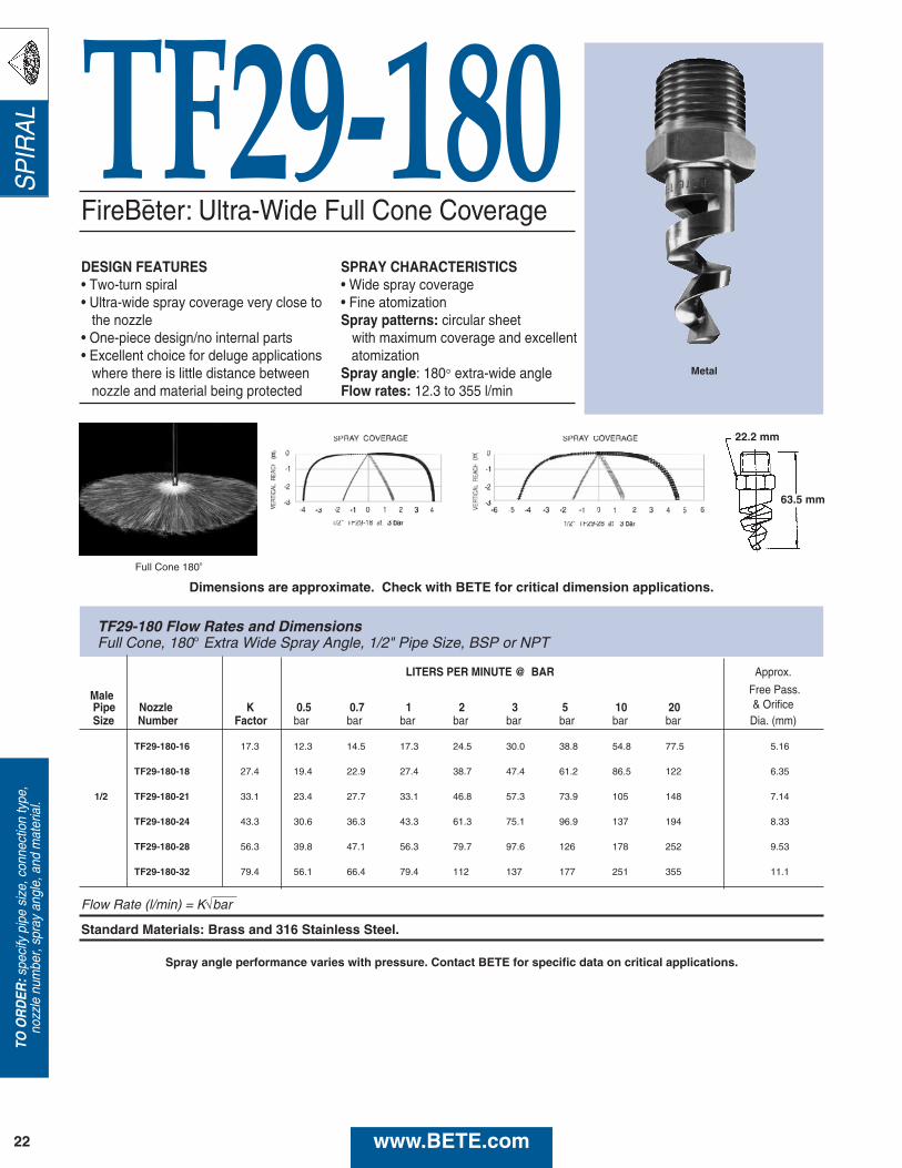
FireBeter: Ultra-Wide Full Cone Coverage
TF29‑180
LITERS PER MINUTE @ BAR Approx.
Free Pass.MalePipe Nozzle K 0.5 0.7 1 2 3 5 10 20 & OrificeSize Number Factor bar bar bar bar bar bar bar bar Dia. (mm)
TF29-180-16 17.3 12.3 14.5 17.3 24.5 30.0 38.8 54.8 77.5 5.16
TF29-180-18 27.4 19.4 22.9 27.4 38.7 47.4 61.2 86.5 122 6.35
1/2 TF29-180-21 33.1 23.4 27.7 33.1 46.8 57.3 73.9 105 148 7.14
TF29-180-24 43.3 30.6 36.3 43.3 61.3 75.1 96.9 137 194 8.33
TF29-180-28 56.3 39.8 47.1 56.3 79.7 97.6 126 178 252 9.53
TF29-180-32 79.4 56.1 66.4 79.4 112 137 177 251 355 11.1
Flow Rate (l/min) = K√bar
Standard Materials: Brass and 316 Stainless Steel.
TO O
RD
ER:s
peci
fy p
ipe
size
, con
nect
ion
type
,no
zzle
num
ber,
spra
y an
gle,
and
mat
eria
l.
22
DESIGN FEATURES• Two-turn spiral• Ultra-wide spray coverage very close to
the nozzle• One-piece design/no internal parts• Excellent choice for deluge applications
where there is little distance betweennozzle and material being protected
SPRAY CHARACTERISTICS• Wide spray coverage• Fine atomizationSpray patterns: circular sheet
with maximum coverage and excellentatomization
Spray angle: 180° extra-wide angleFlow rates: 12.3 to 355 l/min
Metal
SP
IRA
L
Full Cone 180o
63.5 mm
Dimensions are approximate. Check with BETE for critical dimension applications.
www.BETE.com
Spray angle performance varies with pressure. Contact BETE for specific data on critical applications.
22.2 mm
TF29-180 Flow Rates and DimensionsFull Cone, 180° Extra Wide Spray Angle, 1/2" Pipe Size, BSP or NPT
23
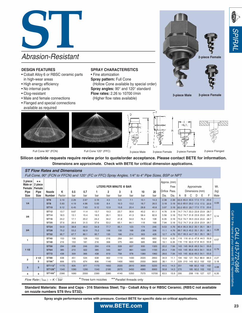
ST
ST Flow Rates and DimensionsFull Cone, 90° (FCN or FFCN) and 120° (FC or FFC) Spray Angles, 1/4" to 4" Pipe Sizes, BSP or NPT
3 pieceMale or 2 piece
Approx. (mm)
Female Female LITERS PER MINUTE @ BAR Free Wt.
Pipe Pipe Nozzle K 0.5 0.7 1 2 3 5 10 20 Orifice Pass. Dimensions (mm) (kg)
Size Size Number Factor bar bar bar bar bar bar bar bar Dia. Dia. A B C D E F Male
1/4ST6 3.19 2.26 2.67 3.19 4.5 5.5 7.1 10.1 14.3 2.38 2.38
0.09ST8 5.93 4.19 4.96 5.93 8.4 10.3 13.2 18.7 26.5 3.18 3.18
ST10 9.12 6.45 7.63 9.12 12.9 15.8 20.4 28.8 40.8 3.97 3.18
3/8
ST12 13.7 9.67 11.4 13.7 19.3 23.7 30.6 43.2 61.1 4.76 3.18
0.14ST14 18.5 13.1 15.4 18.5 26.1 32.0 41.3 58.4 82.6 5.56 3.18
ST16 24.2 17.1 20.2 24.2 34.2 41.8 54.0 76.4 108 6.35 3.18
ST20 37.6 26.6 31.5 37.6 53.2 65.1 84.1 119 168 7.94 3.18
3/4ST24 54.9 38.8 46.0 54.9 77.7 95.1 123 174 246 9.53 4.76
0.28ST28 75.2 53.2 62.9 75.2 106 130 168 238 336 11.1 4.76
ST32 95.7 67.7 80.1 95.7 135 166 214 303 428 12.7 4.76
1ST40 153 108 128 153 216 264 341 483 683 15.9 6.35 0.57ST48 216 153 181 216 306 375 484 685 968 19.1 6.35
1 1/2ST56 294 208 246 294 416 509 657 930 1320 22.2 7.94
0.79ST64 385 272 322 385 545 667 861 1220 1720 25.4 7.94
ST72 438 309 366 438 619 758 978 1380 1960 28.6 7.94
22 1/2 ST88 638 451 534 638 902 1110 1430 2020 2850 34.9 11.1 194 162 121 76.2 88.9 88.9 2.27
3 ST96 806 570 674 806 1140 1400 1800 2550 3600 38.1 11.1 229 210 143 92.2 102 102 3.18
3 3ST112 1170 826 977 1170 1650 2020 2610 3690 5220 44.5 14.3 251 168 92.2 102 102 4.08ST128 1540 1090 1290 1540 2180 2670 3450 4880 6900 50.8 14.3 270 185 92.2 102 102
4 4 ST160 2390 1690 2000 2390 3380 4140 5350 7570 10700 63.5 15.9 295 208 116 127 127 6.35
Flow Rate ( l⁄min ) = K √⎯⎯⎯⎯ bar
Standard Materials: Base and Caps - 316 Stainless Steel; Tip - Cobalt Alloy 6 or RBSC Ceramic. (RBSC not availableon nozzle numbers ST6 thru ST32).
63.5 65.0
65.0 65.0
65.0 65.0
74.7 74.7 23.9 23.9 28.7
73.2 74.7 23.9 23.9 28.7
73.2 74.7 23.9 23.9 28.7
73.2 74.7 23.9 23.9 28.7
17.5 17.5 20.6
17.5 17.5 20.6
17.5 17.5 20.6
30.0
29.2
29.7
33.3
31.8
34.5
31.8
90.4 95.3 35.1 35.1 38.1
89.7 95.3 35.1 35.1 38.1
93.7 95.3 35.1 35.1 38.1
116 116 47.8 44.5 50.8
116 116 47.8 44.5 50.8
143 145 49.3 54.1 55.6
143 145 49.3 54.1 55.6
143 145 49.3 54.1 55.6
30.2
45.2
44.7
61.0
60.5
84.8
85.6
83.8
Approximate
Three turn nozzles*
****
Parallel threads only**
**
Abrasion-Resistant
DESIGN FEATURES• Cobalt Alloy 6 or RBSC ceramic parts
in high-wear areas• High energy efficiency • No internal parts• Clog-resistant• Male and female connections• Flanged and special connections
available as required
SPRAY CHARACTERISTICS• Fine atomizationSpray pattern: Full Cone(Hollow Cone available by special order)
Spray angles: 90° and 120° standard Flow rates: 2.26 to 10700 l/min(Higher flow rates available)
Full Cone 90° (FCN) Full Cone 120° (FFC) 3-piece Male 3-piece Female
3-piece Male
2-piece Female
3-piece Female
CA
LL 413-772-0846C
all for the name of your nearest B
ET
E representative.
SP
IRA
L
2-piece Female
Dimensions are approximate. Check with BETE for critical dimension applications.
www.BETE.com
Silicon carbide requests require review prior to quote/order acceptance. Please contact BETE for information.
Spray angle performance varies with pressure. Contact BETE for specific data on critical applications.
2-piece Flanged
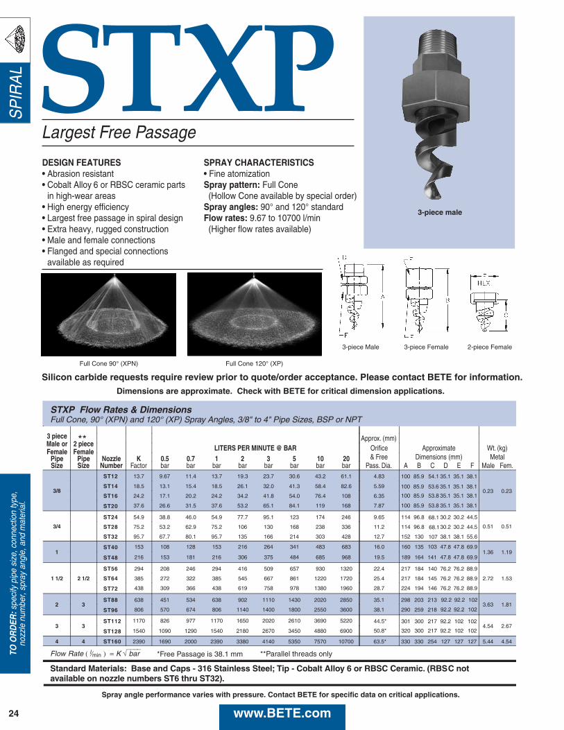
STXP
STXP Flow Rates & DimensionsFull Cone, 90° (XPN) and 120° (XP) Spray Angles, 3/8" to 4" Pipe Sizes, BSP or NPT
3 pieceMale or 2 piece
Approx. (mm)
Female Female LITERS PER MINUTE @ BAR Orifice Approximate Wt. (kg)
Pipe Pipe Nozzle K 0.5 0.7 1 2 3 5 10 20 & Free Dimensions (mm) MetalSize Size Number Factor bar bar bar bar bar bar bar bar Pass. Dia. A B C D E F Male Fem.
3/8
ST12 13.7 9.67 11.4 13.7 19.3 23.7 30.6 43.2 61.1 4.83
0.23 0.23ST14 18.5 13.1 15.4 18.5 26.1 32.0 41.3 58.4 82.6 5.59
ST16 24.2 17.1 20.2 24.2 34.2 41.8 54.0 76.4 108 6.35
ST20 37.6 26.6 31.5 37.6 53.2 65.1 84.1 119 168 7.87
3/4
ST24 54.9 38.8 46.0 54.9 77.7 95.1 123 174 246 9.65 114 96.8 30.2 30.2 44.5
0.51 0.51ST28 75.2 53.2 62.9 75.2 106 130 168 238 336 11.2 114 96.8 30.2 30.2 44.5
ST32 95.7 67.7 80.1 95.7 135 166 214 303 428 12.7 152 130 38.1 38.1 55.6
1ST40 153 108 128 153 216 264 341 483 683 16.0 160 135 47.8 47.8 69.9
1.36 1.19ST48 216 153 181 216 306 375 484 685 968 19.5 189 164 47.8 47.8 69.9
1 1/2 2 1/2
ST56 294 208 246 294 416 509 657 930 1320 22.4 217 184 140 76.2 76.2 88.9
2.72 1.53ST64 385 272 322 385 545 667 861 1220 1720 25.4 217 184 145 76.2 76.2 88.9
ST72 438 309 366 438 619 758 978 1380 1960 28.7 224 194 146 76.2 76.2 88.9
2 3ST88 638 451 534 638 902 1110 1430 2020 2850 35.1 298 203 213
3.63 1.81ST96 806 570 674 806 1140 1400 1800 2550 3600 38.1 290 259 218
3 3ST112 1170 826 977 1170 1650 2020 2610 3690 5220 44.5*
4.54 2.67ST128 1540 1090 1290 1540 2180 2670 3450 4880 6900 50.8*
4 4 ST160 2390 1690 2000 2390 3380 4140 5350 7570 10700 63.5* 330 330 254 127 127 127 5.44 4.54
Flow Rate ( l⁄min ) = K √⎯⎯⎯⎯ bar *Free Passage is 38.1 mm
Standard Materials: Base and Caps - 316 Stainless Steel; Tip - Cobalt Alloy 6 or RBSC Ceramic. (RBSC notavailable on nozzle numbers ST6 thru ST32).
100 85.9 54.1 35.1 35.1 38.1
100 85.9 53.6 35.1 35.1 38.1
100 85.9 53.8 35.1 35.1 38.1
100 85.9 53.8 35.1 35.1 38.1
68.1
68.1
107
103
141
92.2 92.2 102
92.2 92.2 102
301 300 217 92.2 102 102
320 300 217 92.2 102 102
**Parallel threads only
**
Largest Free Passage
DESIGN FEATURES• Abrasion resistant• Cobalt Alloy 6 or RBSC ceramic parts
in high-wear areas• High energy efficiency• Largest free passage in spiral design• Extra heavy, rugged construction• Male and female connections• Flanged and special connections
available as required
SPRAY CHARACTERISTICS• Fine atomizationSpray pattern: Full Cone(Hollow Cone available by special order)
Spray angles: 90° and 120° standard Flow rates: 9.67 to 10700 l/min(Higher flow rates available)
24
Full Cone 90° (XPN) Full Cone 120° (XP)
3-piece Female 2-piece Female3-piece Male
3-piece male
TO O
RD
ER:s
peci
fy p
ipe
size
, con
nect
ion
type
,no
zzle
num
ber,
spra
y an
gle,
and
mat
eria
l.S
PIR
AL
Dimensions are approximate. Check with BETE for critical dimension applications.
www.BETE.com
Silicon carbide requests require review prior to quote/order acceptance. Please contact BETE for information.
Spray angle performance varies with pressure. Contact BETE for specific data on critical applications.
SP
IRA
L
25
CA
LL 413-772-0846C
all for the name of your nearest B
ET
E representative.
LEM
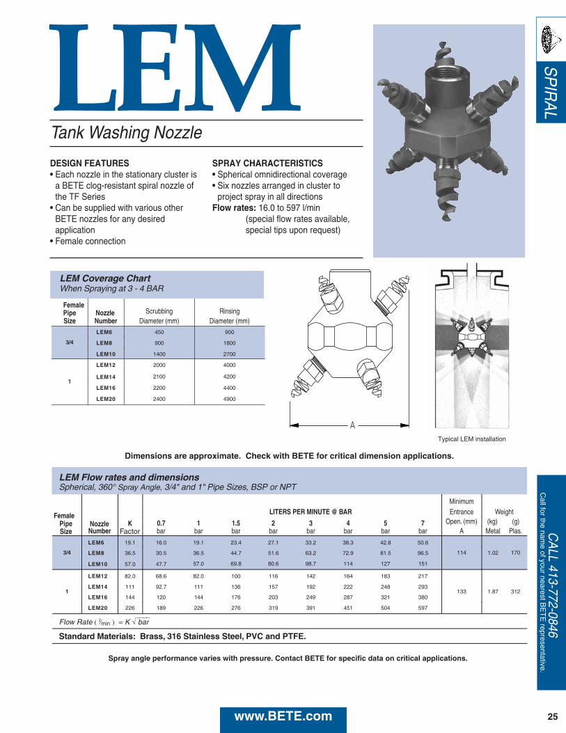
LEM Flow rates and dimensionsSpherical, 360° Spray Angle, 3/4" and 1" Pipe Sizes, BSP or NPT
Minimum
Female LITERS PER MINUTE @ BAR Entrance Weight
K 0.7 1 1.5 2 3 4 5 7 Open. (mm) (kg) (g)Number bar bar bar bar bar bar bar bar A Metal Plas.
3/4
LEM6 19.1 16.0 19.1 23.4 27.1 33.2 38.3 42.8 50.6
114 1.02 170LEM8 36.5 30.5 36.5 44.7 51.6 63.2 72.9 81.5 96.5
LEM10 57.0 47.7 57.0 69.8 80.6 98.7 114 127 151
1
LEM12 82.0 68.6 82.0 100 116 142 164 183 217
133 1.87 312LEM14 111 92.7 111 136 157 192 222 248 293
LEM16 144 120 144 176 203 249 287 321 380
LEM20 226 189 226 276 319 391 451 504 597
Flow Rate ( l⁄min ) = K √⎯⎯⎯⎯ bar
Standard Materials: Brass, 316 Stainless Steel, PVC and PTFE.
NozzlePipeSize Factor
Tank Washing Nozzle
DESIGN FEATURES• Each nozzle in the stationary cluster is
a BETE clog-resistant spiral nozzle ofthe TF Series
• Can be supplied with various otherBETE nozzles for any desiredapplication
• Female connection
SPRAY CHARACTERISTICS• Spherical omnidirectional coverage• Six nozzles arranged in cluster to
project spray in all directionsFlow rates: 16.0 to 597 l/min
(special flow rates available, special tips upon request)
LEM Coverage Chart When Spraying at 3 - 4 BAR
Pipe Nozzle Scrubbing RinsingSize Number Diameter (mm) Diameter (mm)
3/4
LEM6 450 900
LEM8 900 1800
LEM10 1400 2700
1
LEM12 2000 4000
LEM14 2100 4200
LEM16 2200 4400
LEM20 2400 4900
Female
Typical LEM installation
Dimensions are approximate. Check with BETE for critical dimension applications.
www.BETE.com
Spray angle performance varies with pressure. Contact BETE for specific data on critical applications.
N
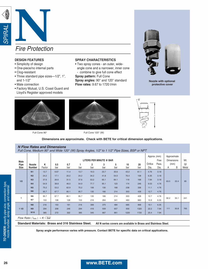
N Flow Rates and DimensionsFull Cone, Medium 90° and Wide 120° (W) Spray Angles, 1/2" to 1 1/2" Pipe Sizes, BSP or NPT
Approx. (mm) Approximate
Male LITERS PER MINUTE @ BAR Free Dimensions Wt.
Pipe Nozzle K 0.5 0.7 1 2 3 5 10 20 Orifice Pass. (mm) (g)Size Number Factor bar bar bar bar bar bar bar bar Dia. Dia. A B Metal
1/2
N1 13.7 9.67 11.4 13.7 19.3 23.7 30.6 43.2 61.1 4.76 3.18
63.5 22.4 85
N2 24.2 17.1 20.2 24.2 34.2 41.8 54.0 76.4 108 6.35 3.18
N3 37.6 26.6 31.5 37.6 53.2 65.1 84.1 119 168 7.94 3.18
N4 54.9 38.8 46.0 54.9 77.7 95.1 123 174 246 9.53 4.76
N5 75.2 53.2 62.9 75.2 106 130 168 238 336 11.1 4.76
N6 95.7 67.7 80.1 95.7 135 166 214 303 428 12.7 4.76
1N6 95.7 67.7 80.1 95.7 135 166 214 303 428 12.7 4.76
92.2 35.1 241N7 153 108 128 153 216 264 341 483 683 15.9 6.35
N8 216 153 181 216 306 375 484 685 968 19.1 6.35
111 50.8 7651 1/2 N9 294 208 246 294 416 509 657 930 1320 22.2 7.94
N10 385 272 322 385 545 667 861 1220 1720 25.4 7.94
Flow Rate ( l⁄min ) = K √⎯⎯⎯⎯ bar
Standard Materials: Brass and 316 Stainless Steel.
Fire Protection
DESIGN FEATURES• Simplicity of design• One-piece/no internal parts• Clog-resistant• Three standard pipe sizes—1/2”, 1”,
and 1-1/2”• Male connection• Factory Mutual, U.S. Coast Guard and
Lloyd's Register approved models
SPRAY CHARACTERISTICS• Two spray cones - an outer, wide-
angle cone and a narrower, inner cone- combine to give full cone effect
Spray pattern: Full ConeSpray angles: 90° and 120° standardFlow rates: 9.67 to 1720 l/min
Full Cone 90° Full Cone 120° (W)
Nozzle with optionalprotective cover
TO O
RD
ER:s
peci
fy p
ipe
size
, con
nect
ion
type
,no
zzle
num
ber,
spra
y an
gle,
and
mat
eria
l.S
PIR
AL
26
Dimensions are approximate. Check with BETE for critical dimension applications.
www.BETE.com
Spray angle performance varies with pressure. Contact BETE for specific data on critical applications.
All N series covers are available in Brass and Stainless Steel.
27
Fire Protection ApprovedThis BETE high‑efficiency spiral wasdesigned specifically with critical fire andexplosion suppression applications in mind.These nozzles feature superior performanceunequalled by traditional whirl nozzles.
SUPERIOR PERFORMANCECHARACTERISTICS• Sprays composed of droplets 30% to 50%
smaller than conventional designs at equivalentpressures
• Extraordinarily large surface area of sprayenhances evaporation and cooling
• Rugged, compact design• Multiple concentric cone spray, unique to spiral
pattern, maximizes contact
SUPERIOR FIRE/LOSS PREVENTIONAPPLICATIONS• Gas wellhead protection• Safeguarding ship-borne cargo• Storage tank protection• Secondary explosion protection in explosive,
dusty environments• Mitigation of HF and other toxic gas releases• Roadway tunnel protection
Certified for useon ships and offshoreinstallations byLloyd’s Register
*U.S. Coast Guard approved
N6 nozzles protect a propane storage tank from fire and explosion.
All modelsFactory MutualApproved
CA
LL 413-772-0846C
all for the name of your nearest B
ET
E representative.
SP
IRA
L
TF 24 150° also available in Factory Mutual approved brass.
ULapproved
www.BETE.com
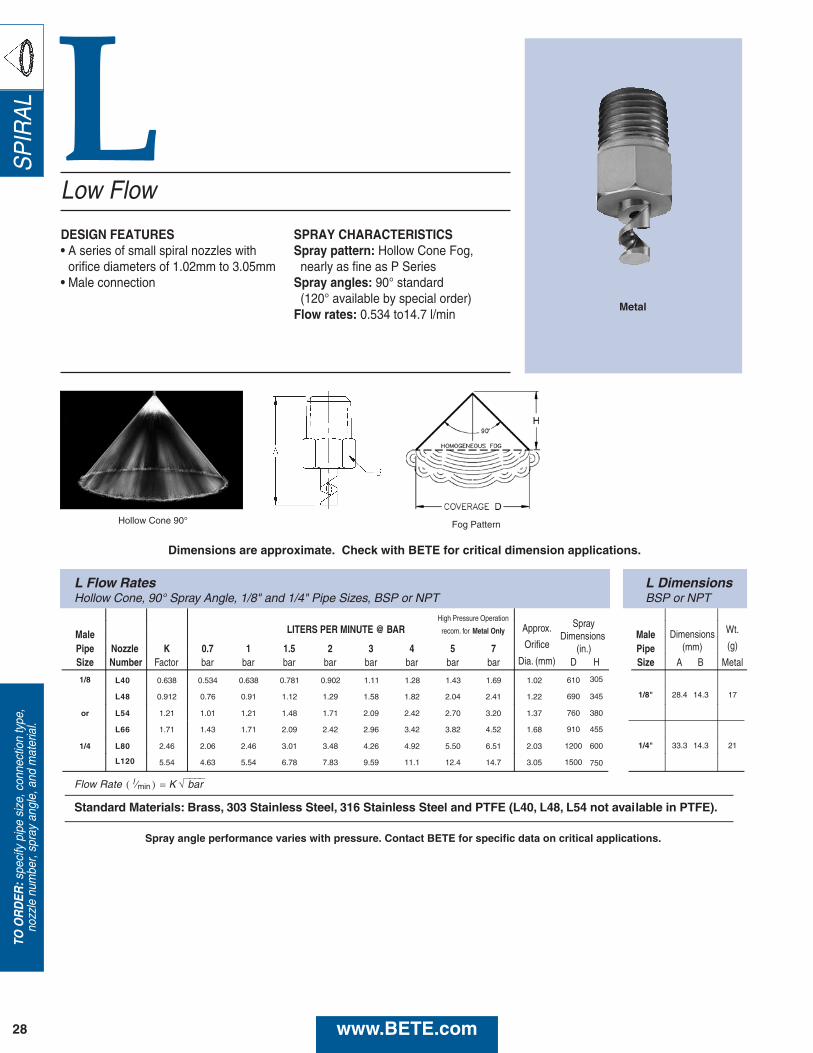
L
L Flow Rates L DimensionsHollow Cone, 90° Spray Angle, 1/8" and 1/4" Pipe Sizes, BSP or NPT BSP or NPT
High Pressure Operation
Male LITERS PER MINUTE @ BAR recom. for Metal Only Approx.Male Wt.
Pipe Nozzle K 0.7 1 1.5 2 3 4 5 7 Orifice PipeDimensions
(mm) (g)
Size Number Factor bar bar bar bar bar bar bar bar Dia. (mm) Size A BD H Metal
1/8 L40 0.638 0.534 0.638 0.781 0.902 1.11 1.28 1.43 1.69 1.02
1/8" 28.4 14.3
610 305
17L48 0.912 0.76 0.91 1.12 1.29 1.58 1.82 2.04 2.41 1.22 690 345
or L54 1.21 1.01 1.21 1.48 1.71 2.09 2.42 2.70 3.20 1.37 760 380
L66 1.71 1.43 1.71 2.09 2.42 2.96 3.42 3.82 4.52 1.68
1/4" 33.3 14.3
910 455
211/4 L80 2.46 2.06 2.46 3.01 3.48 4.26 4.92 5.50 6.51 2.03 1200 600
L120 5.54 4.63 5.54 6.78 7.83 9.59 11.1 12.4 14.7 3.05 1500 750
Flow Rate ( l ⁄min ) = K √⎯⎯⎯⎯ bar
Standard Materials: Brass, 303 Stainless Steel, 316 Stainless Steel and PTFE (L40, L48, L54 not available in PTFE).
SprayDimensions
(in.)
www.BETE.com
Low Flow
DESIGN FEATURES• A series of small spiral nozzles with
orifice diameters of 1.02mm to 3.05mm• Male connection
SPRAY CHARACTERISTICSSpray pattern: Hollow Cone Fog,nearly as fine as P Series
Spray angles: 90° standard(120° available by special order)
Flow rates: 0.534 to14.7 l/min
28
Hollow Cone 90° Fog Pattern
Metal
TO O
RD
ER:s
peci
fy p
ipe
size
, con
nect
ion
type
,no
zzle
num
ber,
spra
y an
gle,
and
mat
eria
l.S
PIR
AL
Dimensions are approximate. Check with BETE for critical dimension applications.
Spray angle performance varies with pressure. Contact BETE for specific data on critical applications.
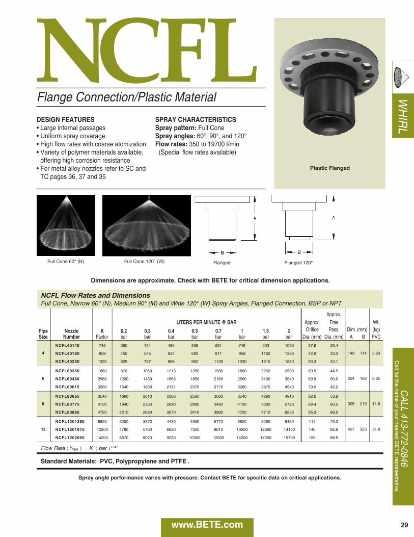
WH
IRL
CA
LL 413-772-0846C
all for the name of your nearest B
ET
E representative.
29
NCFL
NCFL Flow Rates and DimensionsFull Cone, Narrow 60° (N), Medium 90° (M) and Wide 120° (W) Spray Angles, Flanged Connection, BSP or NPT
Approx.
LITERS PER MINUTE @ BAR Approx. Free Wt.
Pipe Nozzle K 0.2 0.3 0.4 0.5 0.7 1 1.5 2 Orifice Pass. Dim. (mm) (kg)Size Number Factor bar bar bar bar bar bar bar bar Dia. (mm) Dia. (mm) A B PVC
4
NCFL40140 746 350 424 485 539 631 746 903 1030 37.6 25.4
149 114 3.63NCFL40180 959 450 545 624 693 811 959 1160 1330 42.9 33.3
NCFL40250 1330 625 757 866 962 1130 1330 1610 1850 50.3 40.1
6
NCFL60350 1860 876 1060 1213 1350 1580 1860 2260 2580 60.5 44.5
254 168 6.35NCFL60480 2560 1200 1450 1663 1850 2160 2560 3100 3540 69.9 50.0
NCFL60615 3280 1540 1860 2131 2370 2770 3280 3970 4540 79.0 42.2
8
NCFL80665 3540 1660 2010 2300 2560 3000 3540 4290 4910 82.6 53.8
305 219 11.8NCFL80775 4130 1940 2350 2690 2980 3490 4130 5000 5720 89.4 60.5
NCFL80885 4720 2210 2680 3070 3410 3990 4720 5710 6530 95.3 66.5
12
NCFL1201280 6820 3200 3870 4430 4930 5770 6820 8260 9450 114 73.2
457 323 31.8NCFL1201910 10200 4780 5780 6620 7350 8610 10200 12300 14100 140 82.6
NCFL1202665 14200 6670 8070 9230 10300 12000 14200 17200 19700 159 88.9
Flow Rate ( l⁄min ) = K ( bar ) 0.47
Standard Materials: PVC, Polypropylene and PTFE .
www.BETE.com
Flange Connection/Plastic Material
DESIGN FEATURES• Large internal passages• Uniform spray coverage• High flow rates with coarse atomization• Variety of polymer materials available,
offering high corrosion resistance• For metal alloy nozzles refer to SC and
TC pages 36, 37 and 35
SPRAY CHARACTERISTICSSpray pattern: Full ConeSpray angles: 60°, 90°, and 120°Flow rates: 350 to 19700 l/min(Special flow rates available)
Full Cone 60° (N) Full Cone 120° (W) Flanged Flanged 120°
Plastic Flanged
Dimensions are approximate. Check with BETE for critical dimension applications.
Spray angle performance varies with pressure. Contact BETE for specific data on critical applications.
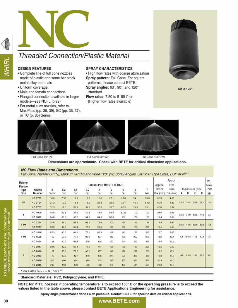
WH
IRL
30
NC
NC Flow Rates and DimensionsFull Cone, Narrow 60°(N), Medium 90°(M) and Wide 120° (W) Spray Angles, 3/4" to 6" Pipe Sizes, BSP or NPT
Male orApprox.
Female LITERS PER MINUTE @ BAR Approx. FreeWt.
Pipe Nozzle K 0.2 0.5 0.7 1 2 3 5 7 Orifice Pass. Dimensions (mm)(g)Size Number Factor bar bar bar bar bar bar bar bar Dia. (mm) Dia. (mm) A B C D
Male
3/4
NC 0703 16.0 7.50 11.5 13.5 16.0 22.1 26.8 34.1 39.9 6.35 4.06
44.5 28.4 53.8 38.1 28NC 0704 21.3 10.0 15.4 18.0 21.3 29.5 35.7 45.4 53.2 6.35 4.83
NC 0707 37.3 17.5 26.9 31.6 37.3 51.7 62.5 79.5 93.1 8.38 5.84
1NC 1009 48.0 22.5 34.6 40.6 48.0 66.4 80.39 102 120 9.65 6.35
55.6 34.9 63.5 44.5 35NC 1012 64.0 30.0 46.2 54.1 64.0 88.6 107 136 160 11.4 7.62
1 1/4NC 1214 74.6 35.0 53.9 63.1 74.6 103 125 159 186 11.9 8.64
82.6 44.5 82.6 50.8 106NC 1217 90.6 42.5 65.4 76.6 90.6 126 152 193 226 13.5 9.65
1 1/2
NC 1516 85.3 40.0 61.6 72.1 85.3 118 143 182 213 12.7 9.65
108 50.8 108 63.5 191NC 1520 107 50.0 77.0 90.1 107 148 179 227 266 14.2 10.4
NC 1524 128 60.0 92.4 108 128 177 214 273 319 15.5 11.2
2
NC 2017 90.6 42.5 65.4 76.6 91 126 152 193 226 13.5 9.65
148 63.5 148 76.2 361
NC 2020 107 50.0 77.0 90.1 107 148 179 227 266 14.2 10.4
NC 2033 176 82.6 127 149 176 244 295 375 439 18.3 14.0
NC 2040 213 100 154 180 213 295 357 454 532 20.3 16.0
NC 2045 240 113 173 203 240 332 402 511 599 21.3 16.0
Flow Rate ( l⁄min ) = K ( bar ) 0.47
Standard Materials: PVC, Polypropylene, and PTFE.
PVC
Threaded Connection/Plastic Material
DESIGN FEATURES• Complete line of full cone nozzles
made of plastic and some bar stockmetal alloy materials
• Uniform coverage• Male and female connections• Flanged connection available in larger
models—see NCFL (p.29)• For metal alloy nozzles, refer to
MaxiPass (pp. 39, 39), SC (pp. 36, 37),or TC (p. 35) Series
SPRAY CHARACTERISTICS• High flow rates with coarse atomizationSpray pattern: Full Cone. For square patterns, please contact BETE.
Spray angles: 60°, 90°, and 120°standard
Flow rates: 7.50 to 8180 l/min(Higher flow rates available)
Full Cone 60° (N) Full Cone 90° (M) Full Cone 120° (W)
Male 120°
TO O
RD
ER:s
peci
fy p
ipe
size
, con
nect
ion
type
,no
zzle
num
ber,
spra
y an
gle,
and
mat
eria
l.
Dimensions are approximate. Check with BETE for critical dimension applications.
www.BETE.com
NOTE for PTFE nozzles: if operating temperature is to exceed 150° C or the operating pressure is to exceed thevalues listed in the table above, please contact BETE Applications Engineering for assistance.
Spray angle performance varies with pressure. Contact BETE for specific data on critical applications.
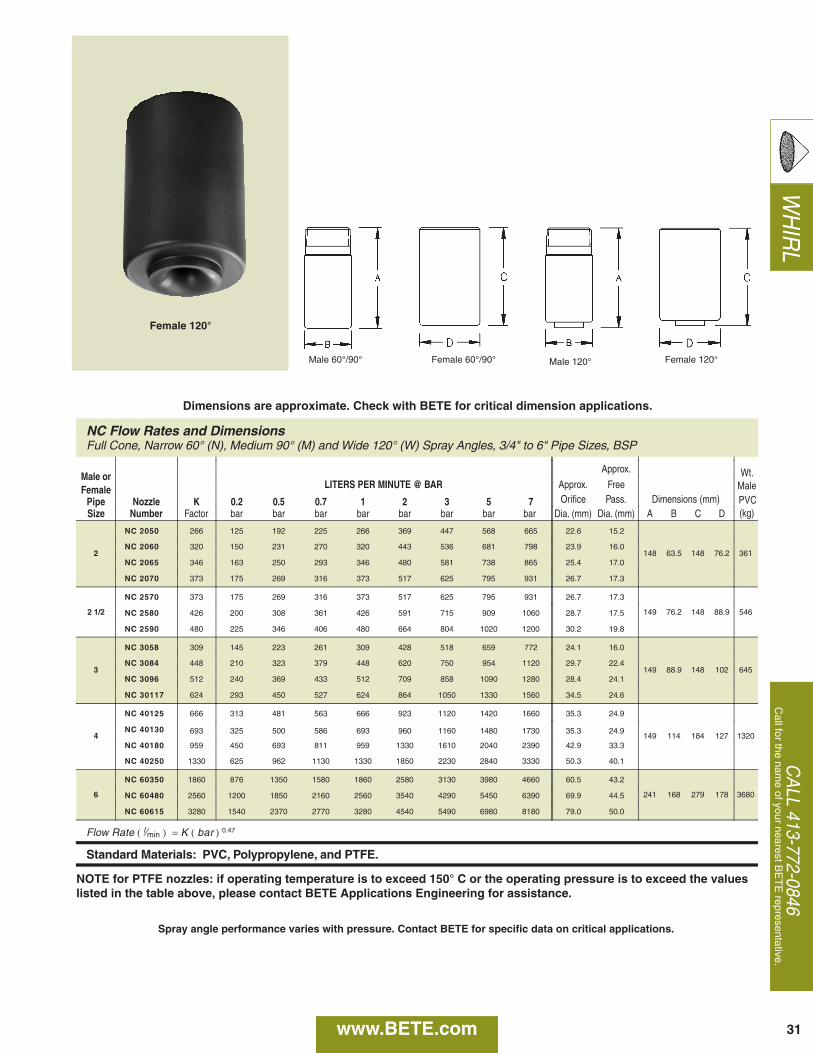
WH
IRL
CA
LL 413-772-0846C
all for the name of your nearest B
ET
E representative.
NC Flow Rates and DimensionsFull Cone, Narrow 60° (N), Medium 90° (M) and Wide 120° (W) Spray Angles, 3/4" to 6" Pipe Sizes, BSP
Male orApprox.
Female LITERS PER MINUTE @ BAR Approx. Free
Pipe Nozzle K 0.2 0.5 0.7 1 2 3 5 7 Orifice Pass. Dimensions (mm)Size Number Factor bar bar bar bar bar bar bar bar Dia. (mm) Dia. (mm) A B C D
2
NC 2050 266 125 192 225 266 369 447 568 665 22.6 15.2
148 63.5 148 76.2 361NC 2060 320 150 231 270 320 443 536 681 798 23.9 16.0
NC 2065 346 163 250 293 346 480 581 738 865 25.4 17.0
NC 2070 373 175 269 316 373 517 625 795 931 26.7 17.3
2 1/2
NC 2570 373 175 269 316 373 517 625 795 931 26.7 17.3
149 76.2 148 88.9 546NC 2580 426 200 308 361 426 591 715 909 1060 28.7 17.5
NC 2590 480 225 346 406 480 664 804 1020 1200 30.2 19.8
3
NC 3058 309 145 223 261 309 428 518 659 772 24.1 16.0
149 88.9 148 102 645NC 3084 448 210 323 379 448 620 750 954 1120 29.7 22.4
NC 3096 512 240 369 433 512 709 858 1090 1280 28.4 24.1
NC 30117 624 293 450 527 624 864 1050 1330 1560 34.5 24.6
4
NC 40125 666 313 481 563 666 923 1120 1420 1660 35.3 24.9
149 114 184 127 1320NC 40130 693 325 500 586 693 960 1160 1480 1730 35.3 24.9
NC 40180 959 450 693 811 959 1330 1610 2040 2390 42.9 33.3
NC 40250 1330 625 962 1130 1330 1850 2230 2840 3330 50.3 40.1
6
NC 60350 1860 876 1350 1580 1860 2580 3130 3980 4660 60.5 43.2
241 168 279 178 3680NC 60480 2560 1200 1850 2160 2560 3540 4290 5450 6390 69.9 44.5
NC 60615 3280 1540 2370 2770 3280 4540 5490 6980 8180 79.0 50.0
Flow Rate ( l⁄min ) = K ( bar ) 0.47
Standard Materials: PVC, Polypropylene, and PTFE.
Wt.
(kg)
MalePVC
Male 120° Female 120°
31
Male 60°/90° Female 60°/90°
Female 120°
Dimensions are approximate. Check with BETE for critical dimension applications.
www.BETE.com
NOTE for PTFE nozzles: if operating temperature is to exceed 150° C or the operating pressure is to exceed the valueslisted in the table above, please contact BETE Applications Engineering for assistance.
Spray angle performance varies with pressure. Contact BETE for specific data on critical applications.
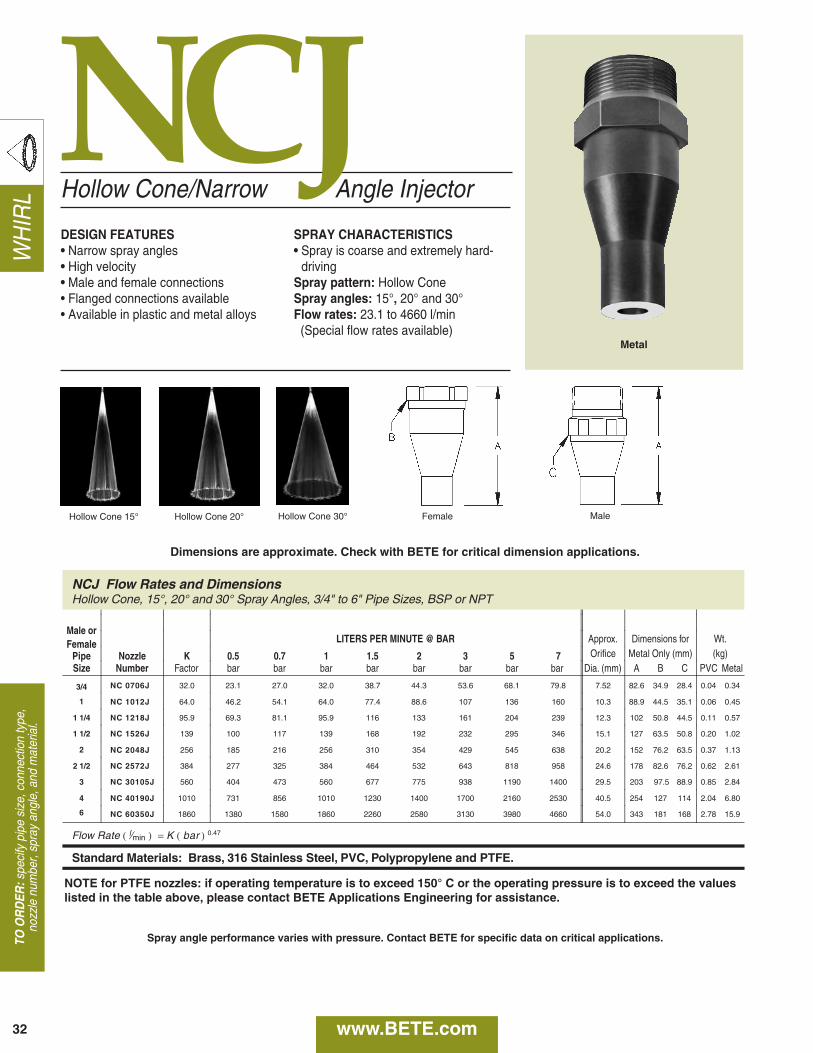
WH
IRL
32
NCJ Flow Rates and DimensionsHollow Cone, 15°, 20° and 30° Spray Angles, 3/4" to 6" Pipe Sizes, BSP or NPT
Male orFemale LITERS PER MINUTE @ BAR Approx. Dimensions for Wt.
Pipe Nozzle K 0.5 0.7 1 1.5 2 3 5 7 Orifice Metal Only (mm) (kg)Size Number Factor bar bar bar bar bar bar bar bar Dia. (mm) A B C PVC Metal
3/4 NC 0706J 32.0 23.1 27.0 32.0 38.7 44.3 53.6 68.1 79.8 7.52 82.6 34.9 28.4 0.04 0.34
1 NC 1012J 64.0 46.2 54.1 64.0 77.4 88.6 107 136 160 10.3 88.9 44.5 35.1 0.06 0.45
1 1/4 NC 1218J 95.9 69.3 81.1 95.9 116 133 161 204 239 12.3 102 50.8 44.5 0.11 0.57
1 1/2 NC 1526J 139 100 117 139 168 192 232 295 346 15.1 127 63.5 50.8 0.20 1.02
2 NC 2048J 256 185 216 256 310 354 429 545 638 20.2 152 76.2 63.5 0.37 1.13
2 1/2 NC 2572J 384 277 325 384 464 532 643 818 958 24.6 178 82.6 76.2 0.62 2.61
3 NC 30105J 560 404 473 560 677 775 938 1190 1400 29.5 203 97.5 88.9 0.85 2.84
4 NC 40190J 1010 731 856 1010 1230 1400 1700 2160 2530 40.5 254 127 114 2.04 6.80
6 NC 60350J 1860 1380 1580 1860 2260 2580 3130 3980 4660 54.0 343 181 168 2.78 15.9
Flow Rate ( l⁄min ) = K ( bar ) 0.47
Standard Materials: Brass, 316 Stainless Steel, PVC, Polypropylene and PTFE.
Hollow Cone/Narrow Angle Injector
DESIGN FEATURES• Narrow spray angles • High velocity• Male and female connections• Flanged connections available• Available in plastic and metal alloys
SPRAY CHARACTERISTICS• Spray is coarse and extremely hard-
drivingSpray pattern: Hollow ConeSpray angles: 15°, 20° and 30°Flow rates: 23.1 to 4660 l/min(Special flow rates available)
Hollow Cone 20° Hollow Cone 30° MaleHollow Cone 15° Female
TO O
RD
ER:s
peci
fy p
ipe
size
, con
nect
ion
type
,no
zzle
num
ber,
spra
y an
gle,
and
mat
eria
l.
Metal
Dimensions are approximate. Check with BETE for critical dimension applications.
NCJ
www.BETE.com
NOTE for PTFE nozzles: if operating temperature is to exceed 150° C or the operating pressure is to exceed the valueslisted in the table above, please contact BETE Applications Engineering for assistance.
Spray angle performance varies with pressure. Contact BETE for specific data on critical applications.
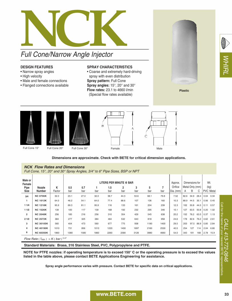
WH
IRL
CA
LL 413-772-0846C
all for the name of your nearest B
ET
E representative.
33
NCK
NCK Flow Rates and DimensionsFull Cone, 15°, 20° and 30° Spray Angles, 3/4" to 6" Pipe Sizes, BSP or NPT
Male orFemale LITERS PER MINUTE @ BAR Approx. Dimensions for Wt.
Pipe Nozzle K 0.5 0.7 1 1.5 2 3 5 7 Orifice Metal Only (mm) (kg)Size Number Factor bar bar bar bar bar bar bar bar Dia. (mm) A B C PVC Metal
3/4 NC 0706K 32.0 23.1 27.0 32.0 38.7 44.3 53.6 68.1 79.8 7.52 82.6 34.9 28.4 0.04 0.34
1 NC 1012K 64.0 46.2 54.1 64.0 77.4 88.6 107 136 160 10.3 88.9 44.5 35.1 0.06 0.45
1 1/4 NC 1218K 95.9 69.3 81.1 95.9 116 133 161 204 239 12.3 102 50.8 44.5 0.11 0.57
1 1/2 NC 1526K 139 100 117 139 168 192 232 295 346 15.1 127 63.5 50.8 0.20 1.02
2 NC 2048K 256 185 216 256 310 354 429 545 638 20.2 152 76.2 63.5 0.37 1.13
2 1/2 NC 2572K 384 277 325 384 464 532 643 818 958 24.6 178 82.6 76.2 0.62 2.61
3 NC 30105K 560 404 473 560 677 775 938 1190 1400 29.5 203 97.5 88.9 0.85 2.84
4 NC 40190K 1010 731 856 1013 1220 1400 1697 2160 2530 40.5 254 127 114 2.04 6.80
6 NC 60350K 1860 1380 1580 1860 2260 2580 3126 3980 4660 54.0 343 181 168 2.78 15.9
Flow Rate ( l⁄min ) = K ( bar ) 0.47
Standard Materials: Brass, 316 Stainless Steel, PVC, Polypropylene and PTFE.
Full Cone/Narrow Angle Injector
DESIGN FEATURES• Narrow spray angles• High velocity• Male and female connections• Flanged connections available
SPRAY CHARACTERISTICS• Coarse and extremely hard-driving
spray with even distributionSpray pattern: Full ConeSpray angles: 15°, 20° and 30°Flow rates: 23.1 to 4660 l/min(Special flow rates available)
Full Cone 15° Full Cone 30° MaleFull Cone 20° Female
Plastic
Dimensions are approximate. Check with BETE for critical dimension applications.
www.BETE.com
NOTE for PTFE nozzles: if operating temperature is to exceed 150° C or the operating pressure is to exceed the valueslisted in the table above, please contact BETE Applications Engineering for assistance.
Spray angle performance varies with pressure. Contact BETE for specific data on critical applications.
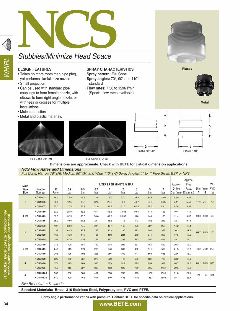
WH
IRL
34
NCS
NCS Flow Rates and DimensionsFull Cone, Narrow 70° (N), Medium 90° (M) and Wide 110° (W) Spray Angles, 1" to 4" Pipe Sizes, BSP or NPT
Approx.
Male LITERS PER MINUTE @ BAR Approx. Free Wt.
Pipe Nozzle K 0.2 0.5 0.7 1 2 3 5 7 Orifice Pass. Dim. (mm) PVCSize Number Factor bar bar bar bar bar bar bar bar Dia. (mm) Dia. (mm) A B (g)
1
NCS1003 16.0 7.50 11.5 13.5 16.0 22.1 26.8 34.1 39.9 5.59 3.81
47.6 35.1 43NCS1005 26.6 12.5 19.2 22.5 26.6 36.9 44.7 56.8 66.5 7.11 5.59
NCS1007 37.3 17.5 26.9 31.6 37.3 51.7 62.5 79.5 93.1 8.38 5.33
1 1/2
NCS1510 53.3 25.0 38.5 45.1 53.3 73.83 89.3 114 133 10.4 7.11
60.3 50.8 85NCS1513 69.3 32.5 50.0 58.6 69.3 95.97 116 148 173 11.4 9.65
NCS1516 85.3 40.0 61.6 72.1 85.3 118 143 182 213 12.7 9.14
2
NCS2020 107 50.0 77.0 90.1 107 148 179 227 266 14.2 10.4
66.7 63.5 170NCS2025 133 62.5 96.2 113 133 185 223 284 333 16.3 11.4
NCS2030 160 75.0 115 135 160 221 268 341 399 17.5 13.2
NCS2035 187 87.6 135 158 187 258 313 397 466 19.1 14.0
2 1/2
NCS2540 213 100 154 180 213 295 357 454 532 20.3 16.0
76.2 76.2 255NCS2545 240 113 173 203 240 332 402 511 599 21.3 16.0
NCS2550 266 125 192 225 266 369 447 568 665 22.6 16.0
3
NCS3060 320 150 231 270 320 443 536 681 798 23.9 16.0
84.1 88.9 383NCS3070 373 175 269 316 373 517 625 795 931 26.7 14.7
NCS3085 453 213 327 383 453 628 759 965 1131 29.5 16.8
4NCS40100 533 250 385 451 533 738 893 1136 1330 31.8 24.1
102 114 567NCS40120 640 300 462 541 640 886 1072 1363 1596 35.1 25.4
Flow Rate ( l⁄min ) = K ( bar ) 0.47
Standard Materials: Brass, 316 Stainless Steel, Polypropylene, PVC and PTFE.
Stubbies/Minimize Head Space
DESIGN FEATURES• Takes no more room than pipe plug,
yet performs like full-size nozzle• Small projection• Can be used with standard pipe
couplings to form female nozzle, withelbows to form right angle nozzle, orwith tees or crosses for multipleinstallations
• Male connection• Metal and plastic materials
SPRAY CHARACTERISTICSSpray pattern: Full ConeSpray angles: 70°, 90° and 110°
standardFlow rates: 7.50 to 1596 l/min(Special flow rates available)
Full Cone 90° (M) Full Cone 110° (W)
Plastic 70°-90° Plastic 110°
Plastic
Metal
TO O
RD
ER:s
peci
fy p
ipe
size
, con
nect
ion
type
,no
zzle
num
ber,
spra
y an
gle,
and
mat
eria
l.
Dimensions are approximate. Check with BETE for critical dimension applications.
www.BETE.comSpray angle performance varies with pressure. Contact BETE for specific data on critical applications.
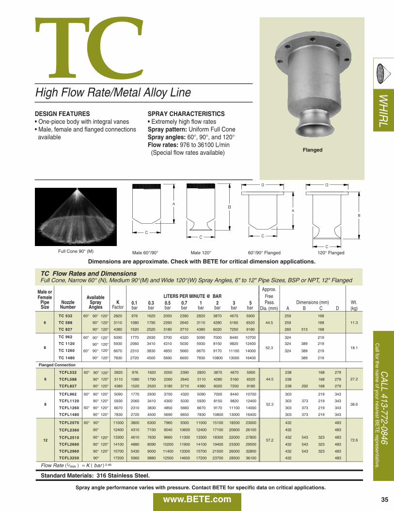
WH
IRL
CA
LL 413-772-0846C
all for the name of your nearest B
ET
E representative.
TC
TC Flow Rates and Dimensions Full Cone, Narrow 60° (N), Medium 90°(M) and Wide 120°(W) Spray Angles, 6" to 12" Pipe Sizes, BSP or NPT, 12" Flanged
Male or Approx.
Female Available LITERS PER MINUTE @ BAR Free Pipe Nozzle Spray K 0.1 0.3 0.5 0.7 1 2 3 5 Pass. Dimensions (mm) Wt. Size Number Angles Factor bar bar bar bar bar bar bar bar Dia. (mm) A B C D (kg)
6
TC 532 60° 2820 976 1620 2050 2390 2820 3870 4670 5900
44.5
259 168
11.3 TC 588 90° 3110 1080 1790 2260 2640 3110 4280 5160 6520 259 168
TC 827 90° 120° 4380 1520 2520 3180 3710 4380 6020 7250 9180 260 313 168
8
TC 962 60° 5090 1770 2930 3700 4320 5090 7000 8440 10700
52.3
324 219
18.1 TC 1120 90° 120° 5930 2060 3410 4310 5030 5930 8150 9820 12400 324 389 219
TC 1260 90° 120° 6670 2310 3830 4850 5660 6670 9170 11100 14000 324 389 219
TC 1480 120° 7830 2720 4500 5690 6650 7830 10800 13000 16400 389 219
Flanged Connection
6
TCFL532 60° 2820 976 1620 2050 2390 2820 3870 4670 5900
44.5
238 168 279
27.2 TCFL588 90° 3110 1080 1790 2260 2640 3110 4280 5160 6520 238 168 279
TCFL827 90° 120° 4380 1520 2520 3180 3710 4380 6020 7250 9180 238 292 168 279
8
TCFL962 60° 90° 5090 1770 2930 3700 4320 5090 7000 8440 10700
52.3
303 219 343
38.6 TCFL1120 90° 120° 5930 2060 3410 4300 5030 5930 8150 9820 12400 303 373 219 343
TCFL1260 90° 120° 6670 2310 3830 4850 5660 6670 9170 11100 14000 303 373 219 343
TCFL1480 90° 120° 7830 2720 4500 5690 6650 7830 10800 13000 16400 303 373 219 343
12
TCFL2070 60° 11000 3800 6300 7960 9300 11000 15100 18200 23000
57.2
432 483
72.6
TCFL2360 90° 12400 4310 7150 9040 10600 12400 17100 20600 26100 432 483
TCFL2510 90° 120° 13300 4610 7630 9660 11300 13300 18300 22000 27800 432 543 323 483
TCFL2660 90° 120° 14100 4880 8090 10200 11900 14100 19400 23300 29500 432 543 323 483
TCFL2960 90° 120° 15700 5430 9000 11400 13300 15700 21500 26000 32800 432 543 323 483
TCFL3250 90° 17200 5960 9880 12500 14600 17200 23700 28500 36100 432 483
Flow Rate ( L⁄min ) = K ( bar ) 0.46
Standard Materials: 316 Stainless Steel.
90°
120°
120°
120°
120°
60°
90°
90°
90°
90°
60°
120°
120°
High Flow Rate/Metal Alloy Line
DESIGN FEATURES• One-piece body with integral vanes• Male, female and flanged connections available
SPRAY CHARACTERISTICS• Extremely high flow ratesSpray pattern: Uniform Full ConeSpray angles: 60°, 90°, and 120°Flow rates: 976 to 36100 L/min(Special flow rates available)
Full Cone 90° (M) Male 60°/90° Male 120°
35
60°/90° Flanged 120° Flanged
Flanged
Dimensions are approximate. Check with BETE for critical dimension applications.
www.BETE.comSpray angle performance varies with pressure. Contact BETE for specific data on critical applications.
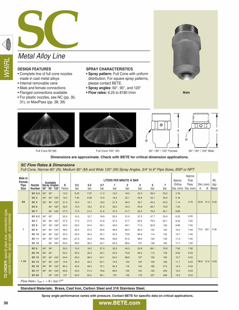
WH
IRL
36
SC
SC Flow Rates & DimensionsFull Cone, Narrow 60° (N), Medium 90° (M) and Wide 120° (W) Spray Angles, 3/4" to 6" Pipe Sizes, BSP or NPT
Male orApprox.
Female AvailableLITERS PER MINUTE @ BAR Approx. Free Wt.
Pipe Nozzle Spray Angles K 0.2 0.3 0.7 1 2 3 5 7 Orifice Pass. Dim. (mm) (kg)Size Number 60° 90° 120° Factor bar bar bar bar bar bar bar bar Dia. (mm) Dia. (mm) A B Metal
3/4
SC 2.5 60° 13.3 6.25 7.57 11.3 13.3 18.5 22.3 28.4 33.3 4.76
4.76 50.8 31.0 0.23
SC 3 60° 90° 16.0 7.50 9.08 13.5 16.0 22.1 26.8 34.1 39.9 5.16
SC 4 60° 90° 120° 21.3 10.0 12.1 18.0 21.3 29.5 35.7 45.4 53.2 7.14
SC 6 120° 32.0 15.0 18.2 27.0 32.0 44.3 53.6 68.1 79.8 7.54
SC 7 90° 37.3 17.5 21.2 31.6 37.3 51.7 62.5 79.5 93.1 8.89
1
SC 4.2 60° 22.4 10.5 12.7 18.9 22.4 31.0 37.5 47.7 55.9 6.35 6.35
73.2 38.1 0.36
SC 7 60° 37.3 17.5 21.2 31.6 37.3 51.7 62.5 79.5 93.1 8.33 7.94
SC 8 60° 42.6 20.0 24.2 36.1 42.6 59.1 71.5 90.9 106 8.89 7.94
SC 9 90° 120° 48.0 22.5 27.2 40.6 48.0 66.4 80.4 102 120 10.2 7.94
SC 10 90° 53.3 25.0 30.3 45.1 53.3 73.8 89.3 114 133 10.7 7.94
SC 11 120° 58.6 27.5 33.3 49.6 58.6 81.2 98.3 125 146 11.2 7.94
SC 12 90° 120° 64.0 30.0 36.3 54.1 64.0 88.6 107 136 160 11.7 7.94
1 1/4
SC 6 60° 32.0 15.0 18.2 27.0 32.0 44.3 53.6 68.1 79.8 7.62 7.62
88.9 47.6 0.59
SC 10 60° 53.3 25.0 30.3 45.1 53.3 73.8 89.3 114 133 9.92 9.53
SC 12 60° 64.0 30.0 36.3 54.1 64.0 88.6 107 136 160 10.7 9.53
SC 14 90° 74.6 35.0 42.4 63.1 74.6 103 125 159 186 11.7 9.53
SC 16 120° 85.3 40.0 48.4 72.1 85.3 118 143 182 213 12.3 9.53
SC 17 90° 90.6 42.5 51.5 76.6 90.6 126 152 193 226 13.5 9.53
SC 20 90° 120° 107 50.0 60.5 90.1 107 148 179 227 266 15.9 9.53
Flow Rate ( l⁄min ) = K ( bar )0.47
Standard Materials: Brass, Cast Iron, Carbon Steel and 316 Stainless Steel.
90°
120°
90°
120°
90°
120°90°
120°90°
60°
60° 120°
90°60°
90°
90°
90° 120°
60° 120°
90°60°
60° 120°
Metal Alloy Line
DESIGN FEATURES• Complete line of full cone nozzles
made in cast metal alloys• Internal removable vane• Male and female connections• Flanged connections available• For plastic nozzles, see NC (pp. 30,
31), or MaxiPass (pp. 38, 39)
SPRAY CHARACTERISTICS• Spray pattern: Full Cone with uniform
distribution. For square spray patterns,please contact BETE.
• Spray angles: 60°, 90°, and 120°• Flow rates: 6.25 to 8180 l/min
Full Cone 90°(M) Full Cone 120° (W) 60° / 90° / 120° Female 60° / 90° / 120° Male
Male
TO O
RD
ER:s
peci
fy p
ipe
size
, con
nect
ion
type
,no
zzle
num
ber,
spra
y an
gle,
and
mat
eria
l.
Dimensions are approximate. Check with BETE for critical dimension applications.
www.BETE.comSpray angle performance varies with pressure. Contact BETE for specific data on critical applications.
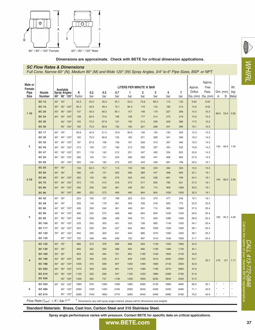
WH
IRL
CA
LL 413-772-0846C
all for the name of your nearest B
ET
E representative.
SC Flow Rates & Dimensions Full Cone, Narrow 60° (N), Medium 90° (M) and Wide 120° (W) Spray Angles, 3/4" to 6" Pipe Sizes, BSP or NPT
Male or Approx.
Female Available LITERS PER MINUTE @ BAR Approx. Free Wt.
Pipe Nozzle Spray Angles K 0.2 0.3 0.7 1 2 3 5 7 Orifice Pass. Dim. (mm) (kg) Size Number 60° 90° 120° Factor bar bar bar bar bar bar bar bar Dia. (mm) Dia. (mm) A B Metal
1 1/2
SC 10 60° 53.3 25.0 30.3 45.1 53.3 73.8 89.3 114 133 9.92 9.53
98.6 55.6 0.82
SC 16 60° 90° 120° 85.3 40.0 48.4 72.1 85.3 118 143 182 213 13.5 9.53
SC 20 60° 90° 120° 107 50.0 60.5 90.1 107 148 179 227 266 14.3 10.3
SC 24 90° 120° 128 60.0 72.6 108 128 177 214 273 319 15.9 10.3
SC 29 120° 155 72.5 87.8 131 155 214 259 329 386 17.5 10.3
SC 30 90° 160 75.0 90.8 135 160 221 268 341 399 19.1 10.3
2
SC 17 60° 90.6 42.5 51.5 76.6 90.6 126 152 193 226 12.3 12.3
130 69.9 1.50
SC 30 60° 160 75.0 90.8 135 160 221 268 341 399 16.3 14.3
SC 35 90° 187 87.6 106 158 187 258 313 397 466 18.3 14.3
SC 40 90° 213 100 121 180 213 295 357 454 532 19.8 14.3
SC 47 120° 251 118 142 212 251 347 420 534 625 24.6 14.3
SC 50 90° 120° 266 125 151 225 266 369 447 568 665 27.9 14.3
SC 60 90° 120° 320 150 182 270 320 443 536 681 798 29.0 19.1
2 1/2
SC 25 60° 133 62.5 75.7 113 133 185 223 284 333 15.5 15.5
160 82.6 2.95
SC 50 60° 266 125 151 225 266 369 447 568 665 22.1 19.1
SC 60 90° 320 150 182 270 320 443 536 681 798 24.4 19.1
SC 70 90° 120° 373 175 212 316 373 517 625 795 931 27.2 19.1
SC 80 90° 120° 426 200 242 361 426 591 715 909 1060 29.2 19.1
SC 90 90° 120° 480 225 272 406 480 664 804 1020 1200 32.3 19.1
3
SC 42 60° 224 105 127 189 224 310 375 477 559 19.1 19.1
182 95.3 4.26
SC 58 60° 309 145 176 261 309 428 518 659 772 22.9 22.9
SC 80 90° 426 200 242 361 426 591 715 909 1060 27.9 25.4
SC 90 90° 120° 480 225 272 406 480 664 804 1020 1200 30.6 25.4
SC 95 120° 506 238 288 428 506 701 849 1080 1260 28.6 25.4
SC 100 90° 533 250 303 451 533 738 893 1140 1330 34.1 25.4
SC 117 120° 624 293 354 527 624 864 1050 1330 1560 36.1 25.4
SC 120 90° 640 300 363 541 640 886 1070 1360 1600 38.1 25.4
SC 135 90° 120° 720 338 409 608 720 997 1210 1530 1800 41.7 25.4
4
SC 125 60° 666 313 378 563 666 923 1120 1420 1660 34.3
33.7 219 121 7.17
SC 130 60° 693 325 393 586 693 960 1160 1480 1730 35.1
SC 160 90° 853 400 484 721 853 1180 1430 1820 2130 40.6
SC 180 90° 120° 959 450 545 811 959 1330 1610 2040 2390 43.7
SC 188 120° 1000 470 569 847 1000 1390 1680 2140 2500 42.9
SC 200 90° 1070 500 605 901 1070 1480 1790 2270 2660 47.6
SC 210 90° 1120 525 636 947 1120 1550 1880 2390 2790 51.6
SC 250 90° 120° 1330 625 757 1130 1330 1850 2230 2840 3330 57.0
6
SC 350 60° 90° 120° 1860 876 1060 1580 1860 2580 3130 3980 4660 66.0 35.1 * * *
SC 480 90° 120° 2560 1200 1450 2160 2560 3540 4290 5450 6390 71.1 42.9 * * *
SC 615 90° 120° 3280 1540 1860 2770 3280 4540 5490 6980 8180 76.2 42.9 * * *
Flow Rate (l ⁄min ) = K ( bar )0.47 * Dimensions vary with spray angle ordered, please call for dimensions and weights
Standard Materials: Brass, Cast Iron, Carbon Steel and 316 Stainless Steel.
90°
60°
90°
120°
90°
90° 120°
60° 120°
60° 120°
90° 60°
60°
90°
90°
60° 120°
60°
60°
60°
90°
90°
120°
60°
90° 60°
120° 60°
90° 60°
120° 60°
90°
90°
60°
60°
90° 60°
120° 60°
120° 60°
37
60° / 90° / 120° Female 60° / 90° / 120° Male
Dimensions are approximate. Check with BETE for critical dimension applications.
www.BETE.comSpray angle performance varies with pressure. Contact BETE for specific data on critical applications.
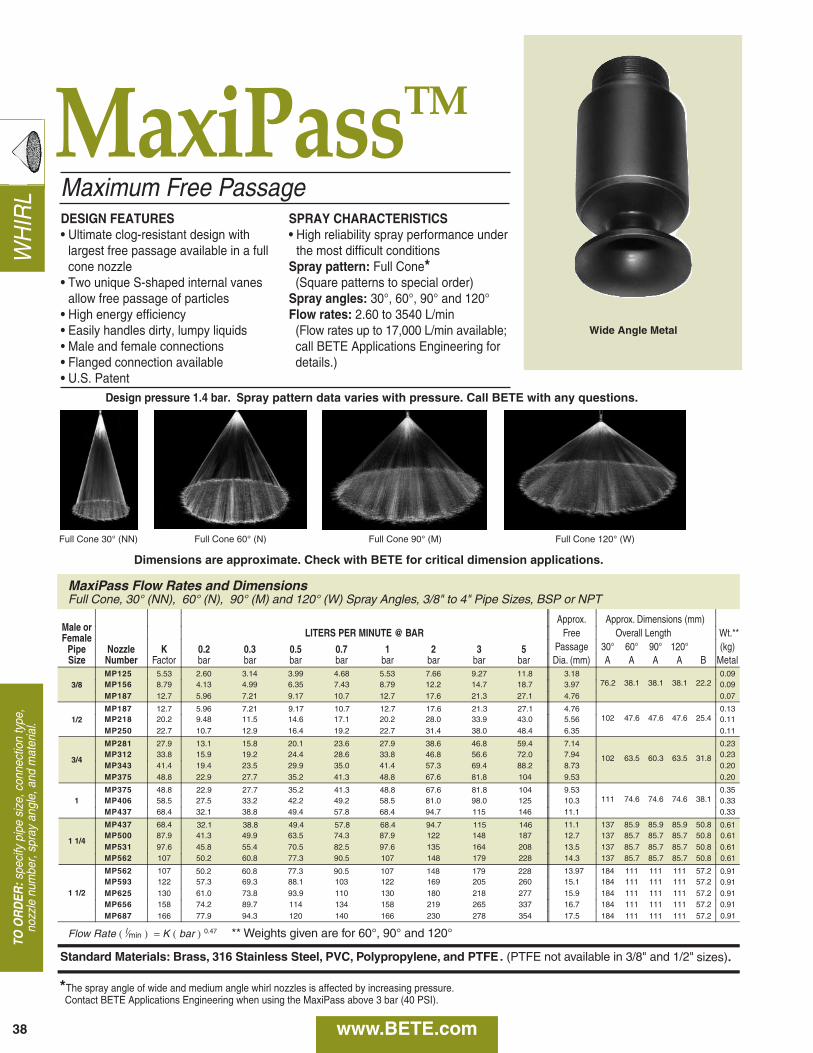
WH
IRL
TO O
RD
ER:s
peci
fy p
ipe
size
, con
nect
ion
type
,no
zzle
num
ber,
spra
y an
gle,
and
mat
eria
l.
38
MaxiPassTM
MaxiPass Flow Rates and Dimensions Full Cone, 30° (NN), 60° (N), 90° (M) and 120° (W) Spray Angles, 3/8" to 4" Pipe Sizes, BSP or NPT
Male or Approx. Approx. Dimensions (mm)
Female LITERS PER MINUTE @ BAR Free Overall Length Wt.**
Pipe Nozzle K 0.2 0.3 0.5 0.7 1 2 3 5 Passage 30° 60° 90° 120° (kg) Size Number Factor bar bar bar bar bar bar bar bar Dia. (mm) A A A A B Metal
3/8 MP125 5.53 2.60 3.14 3.99 4.68 5.53 7.66 9.27 11.8 3.18
76.2 38.1 38.1 38.1 22.2 0.09
MP156 8.79 4.13 4.99 6.35 7.43 8.79 12.2 14.7 18.7 3.97 0.09 MP187 12.7 5.96 7.21 9.17 10.7 12.7 17.6 21.3 27.1 4.76 0.07
1/2 MP187 12.7 5.96 7.21 4.76
102 47.6 47.6 47.6 25.4 0.13
MP218 20.2 9.48 11.5 14.6 17.1 20.2 28.0 33.9 43.0 5.56 0.11 MP250 22.7 10.7 12.9 16.4 19.2 22.7 31.4 38.0 48.4 6.35 0.11
3/4
MP281 27.9 13.1 15.8 20.1 23.6 27.9 38.6 46.8 59.4 7.14
102 63.5 60.3 63.5 31.8
0.23 MP312 33.8 15.9 19.2 24.4 28.6 33.8 46.8 56.6 72.0 7.94 0.23 MP343 41.4 19.4 23.5 29.9 35.0 41.4 57.3 69.4 88.2 8.73 0.20 MP375 48.8 22.9 27.7 35.2 41.3 48.8 67.6 81.8 104 9.53 0.20
1 MP375 48.8 9.53
111 74.6 74.6 74.6 38.1 0.35
MP406 58.5 27.5 33.2 42.2 49.2 58.5 81.0 98.0 125 10.3 0.33 MP437 68.4 32.1 38.8 49.4 57.8 68.4 94.7 115 146 11.1 0.33
1 1/4
MP437 68.4 11.1 137 85.9 85.9 85.9 50.8 MP500 87.9 41.3 49.9 63.5 74.3 87.9 122 148 187 12.7 137 85.7 85.7 85.7 50.8 MP531 97.6 45.8 55.4 70.5 82.5 97.6 135 164 208 13.5 137 85.7 85.7 85.7 50.8 MP562 107 50.2 60.8 77.3 90.5 107 148 179 228 14.3 137 85.7 85.7 85.7 50.8
1 1/2
MP562 107 13.97 184 111 111 111 57.2 MP593 122 57.3 69.3 88.1 103 122 169 205 260 15.1 184 111 111 111 57.2 MP625 130 61.0 73.8 93.9 110 130 180 218 277 15.9 184 111 111 111 57.2 MP656 158 74.2 89.7 114 134 158 219 265 337 16.7 184 111 111 111 57.2 MP687 166 77.9 94.3 120 140 166 230 278 354 17.5 184 111 111 111 57.2
Flow Rate ( l ⁄ min ) = K ( bar ) 0.47 ** Weights given are for 60°, 90° and 120°
Standard Materials: Brass, 316 Stainless Steel, PVC, Polypropylene, and PTFE . (PTFE not available in 3/8" and 1/2"
0.61 0.61 0.61 0.61
0.91 0.91 0.91 0.91 0.91
9.17 10.7 12.7 17.6 21.3 27.1
22.9 27.7 35.2 41.3 48.8 67.6 81.8 104
32.1 38.8 49.4 57.8 68.4 94.7 115 146
50.2 60.8 77.3 90.5 107 148 179 228
sizes) .
Maximum Free PassageDESIGN FEATURES• Ultimate clog-resistant design with
largest free passage available in a fullcone nozzle
• Two unique S-shaped internal vanesallow free passage of particles
• High energy efficiency• Easily handles dirty, lumpy liquids• Male and female connections• Flanged connection available• U.S. Patent
SPRAY CHARACTERISTICS• High reliability spray performance under
the most difficult conditionsSpray pattern: Full Cone*(Square patterns to special order)
Spray angles: 30°, 60°, 90° and 120°Flow rates: 2.60 to 3540 L/min(Flow rates up to 17,000 L/min available;call BETE Applications Engineering fordetails.)
Full Cone 30° (NN) Full Cone 60° (N) Full Cone 120° (W)Full Cone 90° (M)
Wide Angle Metal
*The spray angle of wide and medium angle whirl nozzles is affected by increasing pressure. Contact BETE Applications Engineering when using the MaxiPass above 3 bar (40 PSI).
Dimensions are approximate. Check with BETE for critical dimension applications.
Design pressure 1.4 bar. Spray pattern data varies with pressure. Call BETE with any questions.
www.BETE.com
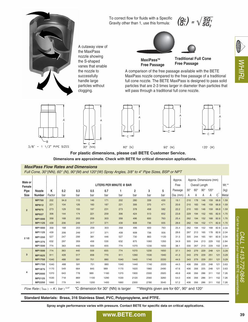
A cutaway view ofthe MaxiPassnozzle showingthe S-shapedvanes that enablethe nozzle tosuccessfullyhandle largeparticles withoutclogging.
MaxiPassTM
Free Passage
Traditional Full ConeFree Passage
A comparison of the free passage available with the BETEMaxiPass nozzle compared to the free passage of a traditionalfull cone nozzle. The BETE MaxiPass is designed to pass solidparticles that are 2-3 times larger in diameter than particles thatwill pass through a traditional full cone nozzle.
CA
LL 1-413-772-0846C
all for the name of your nearest B
ET
E representative.
WH
IRL
MaxiPass Flow Rates and Dimensions Full Cone, 30°(NN), 60° (N), 90°(M) and 120°(W) Spray Angles, 3/8" to 4" Pipe Sizes, BSP or NPT
Male or Approx. Approx. Dimensions (mm)
Female LITERS PER MINUTE @ BAR Free Overall Length Wt.**
Pipe Nozzle K 0.2 0.3 0.5 0.7 1 2 3 5 Passage 30° 60° 90° 120° (kg)
Size Number Factor bar bar bar bar bar bar bar bar Dia. (mm) A A A A C * Metal
2
MP750 202 94.8 115 146 171 202 280 339 430 19.1 210 178 146 159 66.8 1.59
MP812 221 104 126 160 187 221 306 370 471 20.6 210 183 146 159 66.8 1.59
MP875 273 129 155 197 231 273 378 458 582 22.2 210 183 146 159 66.8 1.59
MP937 306 144 174 221 259 306 424 513 652 23.8 229 194 152 165 82.6 1.70
MP1000 358 168 203 259 303 358 496 600 763 25.4 262 194 152 168 82.6 1.70
MP1125 439 206 249 317 371 439 608 736 935 28.6 262 194 152 171 82.6 1.70
2 1/2
MP1125 439 28.6 267 213 165 178 82.6 2.04
MP1250 527 247 299 381 446 527 730 883 1120 31.5 305 244 165 181 82.6 2.04
MP1375 632 297 359 456 535 632 875 1060 1350 34.9 305 244 213 229 102 2.84
MP1500 774 363 440 559 655 774 1070 1230 1650 38.1 330 267 213 229 102 2.84
3
MP1500 774 37.1 343 279 229 248 121 3.29
MP1625 911 428 517 658 770 911 1260 1530 1940 41.3 343 279 229 251
MP1750 1040 488 591 751 880 1040 1440 1740 2220 44.5 343 279 229 251
4
MP1750 1040 44.5 406 356 225 248 121 3.63
MP1875 1170 549 664 845 989 1170 1620 1960 2490 47.6 406 356 225 248 121 3.63
MP2000 1370 643 778 989 1160 1370 1900 2300 2920 49.8 406 356 286 311 152 7.26
MP2125 1530 718 869 1100 1290 1530 2120 2560 3260 54.0 406 356 286 311 152 7.26
MP2250 1660 779 943 1200 1400 1660 2300 2780 3540 57.2 406 356 286 311 152 7.26
Flow Rate ( l ⁄ min ) = K ( bar ) 0.47 *C dimension for 30° (NN) is larger **Weights given are for 60°, 90° and 120°
Standard Materials: Brass, 316 Stainless Steel, PVC, Polypropylene, and PTFE .
121 3.29
121 3.29
MP1000 358 25.4 262 194 152 168 82.6 2.04 168 203 259 303 358 496 600 763
206 249 317 371 439 608 736 935
363 440 559 655 774 1070 1230 1650
488 591 751 880 1040 1440 1740 2220
For plastic dimensions, please call BETE Customer Service.Dimensions are approximate. Check with BETE for critical dimension applications.
www.BETE.com
(Q2)Q1 = √ SG1
SG2
To correct flow for fluids with a SpecificGravity other than 1, use this formula:
39
Spray angle performance varies with pressure. Contact BETE for specific data on critical applications.
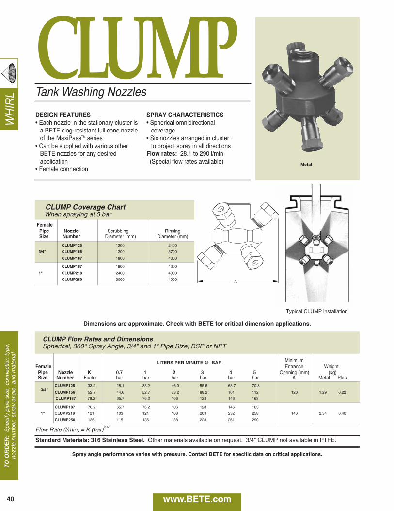
Tank Washing Nozzles
TO O
RD
ER:
Spe
cify
pip
e si
ze, c
onne
ctio
n ty
pe,
nozz
le n
umbe
r, sp
ray
angl
e, a
nd m
ater
ial
WHI
RL
DESIGN FEATURES• Each nozzle in the stationary cluster is
a BETE clog-resistant full cone nozzleof the MaxiPassTM series
• Can be supplied with various other BETE nozzles for any desired application
• Female connection
SPRAY CHARACTERISTICS• Spherical omnidirectional
coverage• Six nozzles arranged in cluster
to project spray in all directionsFlow rates: 28.1 to 290 l/min(Special flow rates available)
CLUMP Flow Rates and DimensionsSpherical, 360° Spray Angle, 3/4" and 1" Pipe Size, BSP or NPT
Typical CLUMP installation
Metal
FemalePipe Nozzle Scrubbing RinsingSize Number Diameter (mm) Diameter (mm)
CLUMP125 1200 2400
3/4" CLUMP156 1200 3700
CLUMP187 1800 4300
CLUMP187 1800 4300
1" CLUMP218 2400 4300
CLUMP250 3000 4900
CLUMP Coverage ChartWhen spraying at 3 bar
LITERS PER MINUTE @ BAR MinimumFemale Entrance WeightPipe Nozzle K 0.7 1 2 3 4 5 Opening (mm) (kg) Size Number Factor bar bar bar bar bar bar A Metal Plas.
CLUMP125 33.2 28.1 33.2 46.0 55.6 63.7 70.8
CLUMP156 52.7 44.6 52.7 73.2 88.2 101 112 120 1.29 0.223/4"
CLUMP187 76.2 65.7 76.2 106 128 146 163
CLUMP187 76.2 65.7 76.2 106 128 146 163
1" CLUMP218 121 103 121 168 203 232 258 146 2.34 0.40
CLUMP250 136 115 136 188 228 261 290
Flow Rate (l/min) = K (bar)0.47
Standard Materials: 316 Stainless Steel. Other materials available on request. 3/4" CLUMP not available in PTFE.
Dimensions are approximate. Check with BETE for critical dimension applications.
CLUMP
www.BETE.com40
Spray angle performance varies with pressure. Contact BETE for specific data on critical applications.
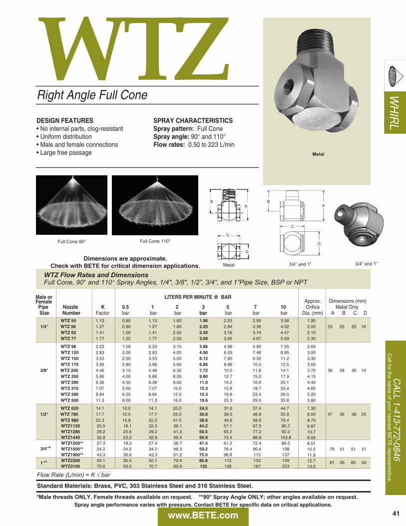
WHIRLDESIGN FEATURES
• No internal parts, clog-resistant• Uniform distribution• Male and female connections • Large free passage
SPRAY CHARACTERISTICSSpray pattern: Full ConeSpray angle: 90° and 110°Flow rates: 0.50 to 223 L/min
Metal
Right Angle Full Cone
WTZ Flow Rates and DimensionsFull Cone, 90° and 110° Spray Angles, 1/4", 3/8", 1/2”, 3/4”, and 1”Pipe Size, BSP or NPT
CA
LL 1-413-772-0846C
all for the name of your nearest B
ET
E representative.
WTZ
www.BETE.com 41Spray angle performance varies with pressure. Contact BETE for specific data on critical applications.
D
C
AB
Metal
AB
C
D
3/4” and 1” 3/4” and 1”
Full Cone 90° Full Cone 110°
Dimensions are approximate. Check with BETE for critical dimension applications.
Flow Rate (L/min) = K √ bar
Standard Materials: Brass, PVC, 303 Stainless Steel and 316 Stainless Steel.
Male or LITERS PER MINUTE @ BARFemale Approx. Dimensions (mm)Pipe Nozzle K 0.5 1 2 3 5 7 10 Orifice Metal OnlySize Number Factor bar bar bar bar bar bar bar Dia. (mm) A B C D
WTZ 50 1.13 0.80 1.13 1.60 1.96 2.53 2.99 3.58 1.901/4” WTZ 56 1.27 0.90 1.27 1.80 2.20 2.84 3.36 4.02 2.00 33 25 20 16
WTZ 62 1.41 1.00 1.41 2.00 2.45 3.16 3.74 4.47 2.10WTZ 77 1.77 1.25 1.77 2.50 3.06 3.95 4.67 5.59 2.30
WTZ 98 2.23 1.58 2.23 3.15 3.86 4.98 5.90 7.05 2.60WTZ 120 2.83 2.00 2.83 4.00 4.90 6.33 7.48 8.95 3.00WTZ 150 3.53 2.50 3.53 5.00 6.12 7.90 9.35 11.2 3.30WTZ 170 3.96 2.80 3.96 5.60 6.86 8.86 10.5 12.5 3.50
3/8" WTZ 200 4.46 3.15 4.46 6.30 7.72 10.0 11.8 14.1 3.70 38 28 30 19WTZ 250 5.66 4.00 5.66 8.00 9.80 12.7 15.0 17.9 4.15WTZ 280 6.36 4.50 6.36 9.00 11.0 14.2 16.8 20.1 4.40WTZ 310 7.07 5.00 7.07 10.0 12.3 15.8 18.7 22.4 4.65WTZ 390 8.84 6.25 8.84 12.5 15.3 19.8 23.4 28.0 5.20WTZ 500 11.3 8.00 11.3 16.0 19.6 25.3 29.9 35.8 5.80
WTZ 620 14.1 10.0 14.1 20.0 24.5 31.6 37.4 44.7 7.301/2" WTZ 780 17.7 12.5 17.7 25.0 30.6 39.5 46.8 55.9 8.00 47 35 38 25
WTZ 980 22.3 15.8 22.3 31.5 38.6 49.8 58.9 70.4 8.70WTZ1120 25.5 18.1 25.5 36.1 44.2 57.1 67.5 80.7 9.87WTZ1280 29.2 20.6 29.2 41.3 50.5 65.2 77.2 92.2 10.7WTZ1440 32.8 23.2 32.8 46.4 56.8 73.4 86.8 103.8 9.93WTZ1200** 27.3 19.3 27.4 38.7 47.4 61.2 72.4 86.5 8.51
3/4”* WTZ1500** 34.2 24.2 34.2 48.3 59.2 76.4 90.4 108 10.5 76 51 51 51WTZ1900** 43.3 30.6 43.3 61.2 75.0 96.8 115 137 11.9WTZ2200 50.1 35.5 50.1 70.9 86.8 112 133 159 12.7 81 56 65 63WTZ3100 70.6 50.0 70.7 99.9 122 158 187 223 13.5
1”*
*Male threads ONLY. Female threads available on request. **90° Spray Angle ONLY; other angles available on request.

WH
IRL
FemaleMale
WTRight Angle/Hollow Cone
DESIGN FEATURES• Conventional design using tangential
whirl method of atomization• Durable• Use where a circular pattern is required
or in large area multiple installationswhere there is considerable over-lapping of sprays
• Male and female connections• Large free passage
SPRAY CHARACTERISTICSSpray pattern: Hollow ConeSpray angles: 70° to 120°Flow rates: 0.125 to 145 l/min
Hollow Cone 80° Hollow Cone 120°
Male Metal
TO O
RD
ER:s
peci
fy p
ipe
size
, con
nect
ion
type
,no
zzle
num
ber,
spra
y an
gle,
and
mat
eria
l.
WT Flow Rates and DimensionsHollow Cone, Medium and Extra Wide Spray Angles, 1/8" to 3/4" Pipe Sizes, BSP or NPT
Male orFemale LITERS PER MINUTE @ BAR Approx. (mm)
Pipe Nozzle Spray K 0.3 0.5 0.7 1 2 3 5 7 Inlet Orifice Dimensions for Metal Only (mm) Wt. (g)Size Number Angle Factor bar bar bar bar bar bar bar bar Dia. Dia. A B C D E F G H Metal Plas.
1/8
WT10 70° 110° 0.228 0.125 0.161 0.191 0.228 0.322 0.395 0.510 0.603 1.02 1.17
28.4 22.4 16.0 12.7 22.4 16.0 16.5 12.7 28 14
WT20 70° 115° 0.456 0.250 0.322 0.381 0.456 0.645 0.789 1.02 1.21 1.52 1.52
WT40 70° 0.912 0.499 0.645 0.763 0.912 1.29 1.58 2.04 2.41 2.29 2.29
WT50 115° 1.14 0.624 0.806 0.953 1.14 1.61 1.97 2.55 3.01 2.29 2.29
WT60 70° 115° 1.37 0.749 0.967 1.14 1.37 1.93 2.37 3.06 3.62 2.54 2.79
WT70 115° 1.60 0.874 1.13 1.33 1.60 2.26 2.76 3.57 4.22 2.54 2.79
WT80 120° 1.82 0.999 1.29 1.53 1.82 2.58 3.16 4.08 4.82 2.79 3.05
WT100 70° 115° 2.28 1.25 1.61 1.91 2.28 3.22 3.95 5.10 6.03 3.30 3.30
WT130 120° 2.96 1.62 2.09 2.48 2.96 4.19 5.13 6.62 7.84 3.56 3.56
WT160 70° 3.65 2.00 2.58 3.05 3.65 5.16 6.32 8.15 9.65 3.81 4.06
WT180 120° 4.10 2.25 2.90 3.43 4.10 5.80 7.10 9.17 10.9 4.32 4.06
WT200 70° 4.56 2.50 3.22 3.81 4.56 6.45 7.89 10.2 12.1 4.32 4.83
1/4
WT12 80° 0.273 0.150 0.193 0.229 0.273 0.387 0.474 0.611 0.724 1.02 1.27
33.3 25.4 20.1 16.0 28.4 20.6 20.1 16.0 85 21
WT18 80° 0.410 0.225 0.290 0.343 0.410 0.580 0.710 0.917 1.09 1.52 1.52
WT20 70° 110° 0.456 0.250 0.322 0.381 0.456 0.645 0.789 1.02 1.21 1.52 1.52
WT27 80° 0.615 0.337 0.435 0.515 0.615 0.870 1.07 1.38 1.63 1.78 2.03
WT35 100° 0.798 0.437 0.564 0.667 0.798 1.13 1.38 1.78 2.11 2.03 2.29
WT40 70° 80° 0.912 0.499 0.645 0.763 0.912 1.29 1.58 2.04 2.41 2.03 2.29
WT42 120° 0.957 0.524 0.677 0.801 0.957 1.35 1.66 2.14 2.53 2.03 2.29
WT48 105° 1.09 0.599 0.773 0.915 1.09 1.55 1.89 2.45 2.89 2.29 2.79
Flow Rate ( l⁄min ) = K √⎯⎯⎯⎯ bar
Standard Materials: Brass, 303 Stainless Steel and 316 Stainless Steel.
B
D
Dimensions are approximate. Check with BETE for critical dimension applications.
www.BETE.com42
Spray angle performance varies with pressure. Contact BETE for specific data on critical applications.
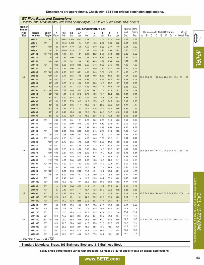
WH
IRL
CA
LL 413-772-0846C
all for the name of your nearest B
ET
E representative.
WT Flow Rates and DimensionsHollow Cone, Medium and Extra Wide Spray Angles, 1/8" to 3/4" Pipe Sizes, BSP or NPT
Male orFemale LITERS PER MINUTE @ BAR Approx. (mm)
Pipe Nozzle Spray K 0.3 0.5 0.7 1 2 3 5 7 Inlet Orifice Dimensions for Metal Only (mm) Wt. (g)Size Number Angle Factor bar bar bar bar bar bar bar bar Dia. Dia. A B C D E F G H Metal Plas.
1/4
WT53 80° 1.21 0.662 0.854 1.01 1.21 1.71 2.09 2.70 3.20
33.3 25.4 20.1 16.0 28.4 20.6 20.1 16.0 85 21
WT60 70° 1.37 0.749 0.967 1.14 1.37 1.93 2.37 3.06 3.62
WT68 120° 1.55 0.849 1.10 1.30 1.55 2.19 2.68 3.47 4.10
WT80 120° 1.82 0.999 1.29 1.53 1.82 2.58 3.16 4.08 4.82
WT100 70° 115° 2.28 1.25 1.61 1.91 2.28 3.22 3.95 5.10 6.03
WT130 120° 2.96 1.62 2.09 2.48 2.96 4.19 5.13 6.62 7.84
WT150 120° 3.42 1.87 2.42 2.86 3.42 4.83 5.92 7.64 9.04
WT160 70° 3.65 2.00 2.58 3.05 3.65 5.16 6.32 8.15 9.65
WT180 120° 4.10 2.25 2.90 3.43 4.10 5.80 7.10 9.17 10.9
WT200 70° 120° 4.56 2.50 3.22 3.81 4.56 6.45 7.89 10.19 12.1
WT220 120° 5.01 2.75 3.55 4.19 5.01 7.09 8.68 11.2 13.3
WT240 120° 5.47 3.00 3.87 4.58 5.47 7.73 9.47 12.2 14.5
WT260 80° 5.93 3.25 4.19 4.96 5.93 8.38 10.3 13.2 15.7
WT280 80° 6.38 3.49 4.51 5.34 6.38 9.02 11.1 14.3 16.9
WT300 70° 100° 6.84 3.74 4.83 5.72 6.84 9.67 11.8 15.3 18.1
WT340 80° 7.75 4.24 5.48 6.48 7.75 11.0 13.4 17.3 20.5
WT400 80° 9.12 4.99 6.45 7.63 9.12 12.9 15.8 20.4 24.1
WT480 80° 10.9 5.99 7.73 9.15 10.9 15.5 18.9 24.5 28.9
WT580 80° 13.2 7.24 9.35 11.1 13.2 18.7 22.9 29.6 35.0
WT640 80° 14.6 7.99 10.3 12.2 14.6 20.6 25.3 32.6 38.6
WT680 80° 15.5 8.49 11.0 13.0 15.5 21.9 26.8 34.7 41.0
WT800 80° 18.2 9.99 12.9 15.3 18.2 25.8 31.6 40.8 48.2
3/8
WT100 70° 2.28 1.25 1.61 1.91 2.28 3.22 3.95 5.10 6.03
38.1 28.4 24.6 19.1 34.0 24.6 24.6 19.1 85 21
WT130 120° 2.96 1.62 2.09 2.48 2.96 4.19 5.13 6.62 7.84
WT150 120° 3.42 1.87 2.42 2.86 3.42 4.83 5.92 7.64 9.04
WT160 70° 3.65 2.00 2.58 3.05 3.65 5.16 6.32 8.15 9.65
WT180 120° 4.10 2.25 2.90 3.43 4.10 5.80 7.10 9.17 10.9
WT200 70° 115° 4.56 2.50 3.22 3.81 4.56 6.45 7.89 10.2 12.1
WT220 120° 5.01 2.75 3.55 4.19 5.01 7.09 8.68 11.2 13.3
WT240 125° 5.47 3.00 3.87 4.58 5.47 7.73 9.47 12.2 14.5
WT260 120° 5.93 3.25 4.19 4.96 5.93 8.38 10.3 13.2 15.7
WT270 120° 6.15 3.37 4.35 5.15 6.15 8.70 10.7 13.8 16.3
WT300 70° 115° 6.84 3.74 4.83 5.72 6.84 9.67 11.8 15.3 18.1
WT350 115° 7.98 4.37 5.64 6.67 7.98 11.3 13.8 17.8 21.1
WT400 70° 105° 9.12 4.99 6.45 7.63 9.12 12.9 15.8 20.4 24.1
WT440 105° 10.0 5.49 7.09 8.39 10.0 14.2 17.4 22.4 26.5
WT500 70° 105° 11.4 6.24 8.06 9.53 11.4 16.1 19.7 25.5 30.1
WT560 105° 12.8 6.99 9.02 10.7 12.8 18.0 22.1 28.5 33.8
WT600 70° 13.7 7.49 9.67 11.4 13.7 19.3 23.7 30.6 36.2
WT1000 70° 22.8 12.5 16.1 19.1 22.8 32.2 39.5 51.0 60.3
1/2
WT500 70° 11.4 6.24 8.06 9.53 11.4 16.1 19.7 25.5 30.1
47.5 34.8 31.8 25.4 46.0 33.3 31.8 25.4 276 113
WT600 70° 13.7 7.49 9.67 11.4 13.7 19.3 23.7 30.6 36.2
WT800 70° 18.2 9.99 12.9 15.3 18.2 25.8 31.6 40.8 48.2
WT1000 70° 110° 22.8 12.5 16.1 19.1 22.8 32.2 39.5 51.0 60.3
WT1200 70° 27.3 15.0 19.3 22.9 27.3 38.7 47.4 61.1 72.4
3/4
WT800 70° 18.2 9.99 12.9 15.3 18.2 25.8 31.6 40.8 48.2
57.2 41.1 38.1 31.8 55.6 39.6 38.1 31.8 397 227
WT1000 70° 22.8 12.5 16.1 19.1 22.8 32.2 39.5 51.0 60.3
WT1200 70° 27.3 15.0 19.3 22.9 27.3 38.7 47.4 61.1 72.4
WT1400 80° 31.9 17.5 22.6 26.7 31.9 45.1 55.3 71.3 84.4
WT1600 80° 115° 36.5 20.0 25.8 30.5 36.5 51.6 63.2 81.5 96.5
WT1800 80° 41.0 22.5 29.0 34.3 41.0 58.0 71.0 91.7 109
WT2000 90° 45.6 25.0 32.2 38.1 45.6 64.5 78.9 102 121
WT2200 90° 50.1 27.5 35.5 41.9 50.1 70.9 86.8 112 133
WT2400 90° 54.7 30.0 38.7 45.8 54.7 77.3 94.7 122 145
Flow Rate ( l⁄min ) = K √⎯⎯⎯⎯ bar
Standard Materials: Brass, 303 Stainless Steel and 316 Stainless Steel.
2.29 2.79
2.54 2.79
2.54 3.30
3.30 3.30
3.30 3.56
3.81 4.06
4.06 4.32
4.06 4.32
4.57 4.57
4.57 4.83
4.57 5.59
5.08 5.08
5.08 5.08
5.08 5.59
5.08 5.59
5.59 6.10
6.35 7.11
6.35 6.86
6.86 7.62
6.86 7.62
6.86 8.64
6.86 8.64
3.56 3.81
3.56 4.57
4.32 4.57
4.32 4.57
4.32 4.83
4.83 5.08
4.83 5.08
4.83 5.08
4.83 5.84
5.08 5.84
5.08 5.84
6.10 6.35
6.10 6.86
6.60 7.62
6.60 7.11
6.60 7.87
7.87 7.87
8.64 9.65
7.62 7.62
8.38 7.87
9.14 9.14
9.14 11.2
10.2 12.2
9.14 9.65
10.2 11.2
11.2 11.2
11.9 12.2
12.2 13.0
12.7 14.2
13.2 15.0
13.5 16.0
14.0 17.5
43
Dimensions are approximate. Check with BETE for critical dimension applications.
www.BETE.com
Spray angle performance varies with pressure. Contact BETE for specific data on critical applications.
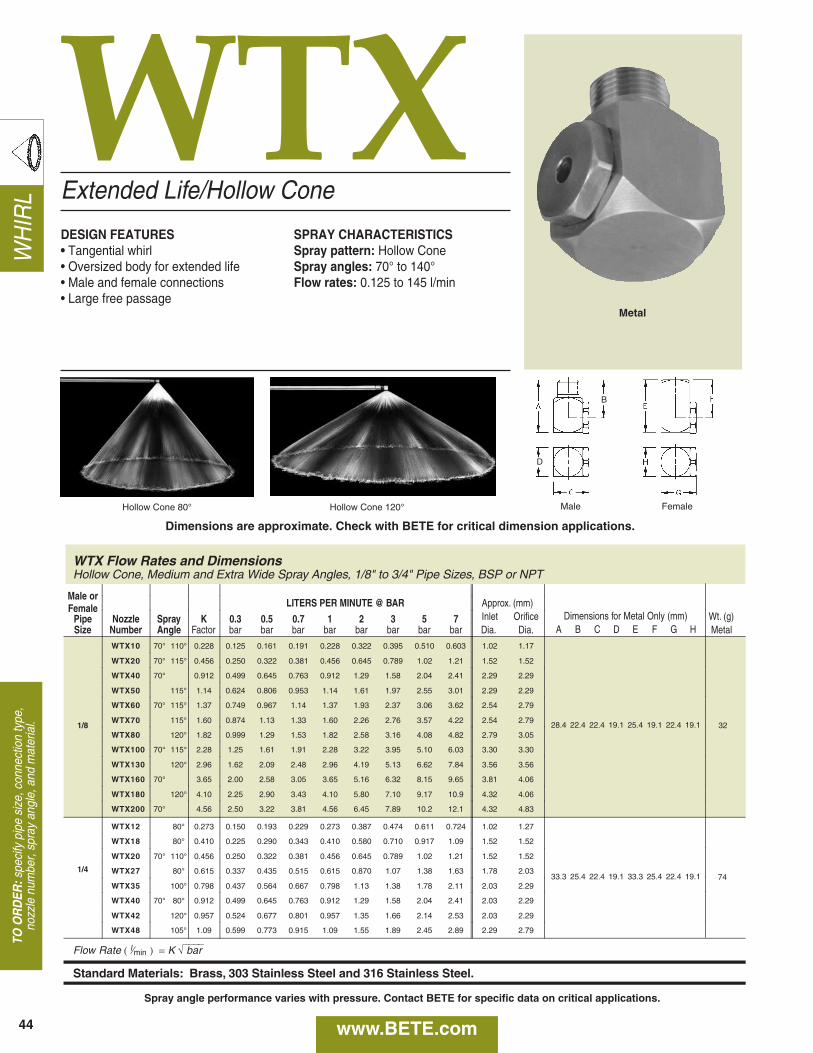
WH
IRL
WTXExtended Life/Hollow Cone
DESIGN FEATURES• Tangential whirl• Oversized body for extended life• Male and female connections• Large free passage
SPRAY CHARACTERISTICSSpray pattern: Hollow ConeSpray angles: 70° to 140°Flow rates: 0.125 to 145 l/min
Hollow Cone 80° Hollow Cone 120° Male Female
44
Metal
TO O
RD
ER:s
peci
fy p
ipe
size
, con
nect
ion
type
,no
zzle
num
ber,
spra
y an
gle,
and
mat
eria
l.
WTX Flow Rates and DimensionsHollow Cone, Medium and Extra Wide Spray Angles, 1/8" to 3/4" Pipe Sizes, BSP or NPT
Male orFemale LITERS PER MINUTE @ BAR Approx. (mm)
Pipe Nozzle Spray K 0.3 0.5 0.7 1 2 3 5 7 Inlet Orifice Dimensions for Metal Only (mm) Wt. (g)Size Number Angle Factor bar bar bar bar bar bar bar bar Dia. Dia. A B C D E F G H Metal
1/8
WTX10 70° 110° 0.228 0.125 0.161 0.191 0.228 0.322 0.395 0.510 0.603 1.02 1.17
28.4 22.4 22.4 19.1 25.4 19.1 22.4 19.1 32
WTX20 70° 115° 0.456 0.250 0.322 0.381 0.456 0.645 0.789 1.02 1.21 1.52 1.52
WTX40 70° 0.912 0.499 0.645 0.763 0.912 1.29 1.58 2.04 2.41 2.29 2.29
WTX50 115° 1.14 0.624 0.806 0.953 1.14 1.61 1.97 2.55 3.01 2.29 2.29
WTX60 70° 115° 1.37 0.749 0.967 1.14 1.37 1.93 2.37 3.06 3.62 2.54 2.79
WTX70 115° 1.60 0.874 1.13 1.33 1.60 2.26 2.76 3.57 4.22 2.54 2.79
WTX80 120° 1.82 0.999 1.29 1.53 1.82 2.58 3.16 4.08 4.82 2.79 3.05
WTX100 70° 115° 2.28 1.25 1.61 1.91 2.28 3.22 3.95 5.10 6.03 3.30 3.30
WTX130 120° 2.96 1.62 2.09 2.48 2.96 4.19 5.13 6.62 7.84 3.56 3.56
WTX160 70° 3.65 2.00 2.58 3.05 3.65 5.16 6.32 8.15 9.65 3.81 4.06
WTX180 120° 4.10 2.25 2.90 3.43 4.10 5.80 7.10 9.17 10.9 4.32 4.06
WTX200 70° 4.56 2.50 3.22 3.81 4.56 6.45 7.89 10.2 12.1 4.32 4.83
1/4
WTX12 80° 0.273 0.150 0.193 0.229 0.273 0.387 0.474 0.611 0.724 1.02 1.27
33.3 25.4 22.4 19.1 33.3 25.4 22.4 19.1 74
WTX18 80° 0.410 0.225 0.290 0.343 0.410 0.580 0.710 0.917 1.09 1.52 1.52
WTX20 70° 110° 0.456 0.250 0.322 0.381 0.456 0.645 0.789 1.02 1.21 1.52 1.52
WTX27 80° 0.615 0.337 0.435 0.515 0.615 0.870 1.07 1.38 1.63 1.78 2.03
WTX35 100° 0.798 0.437 0.564 0.667 0.798 1.13 1.38 1.78 2.11 2.03 2.29
WTX40 70° 80° 0.912 0.499 0.645 0.763 0.912 1.29 1.58 2.04 2.41 2.03 2.29
WTX42 120° 0.957 0.524 0.677 0.801 0.957 1.35 1.66 2.14 2.53 2.03 2.29
WTX48 105° 1.09 0.599 0.773 0.915 1.09 1.55 1.89 2.45 2.89 2.29 2.79
Flow Rate ( l⁄min ) = K √⎯⎯⎯⎯ bar
Standard Materials: Brass, 303 Stainless Steel and 316 Stainless Steel.
B
D
Dimensions are approximate. Check with BETE for critical dimension applications.
www.BETE.com
Spray angle performance varies with pressure. Contact BETE for specific data on critical applications.
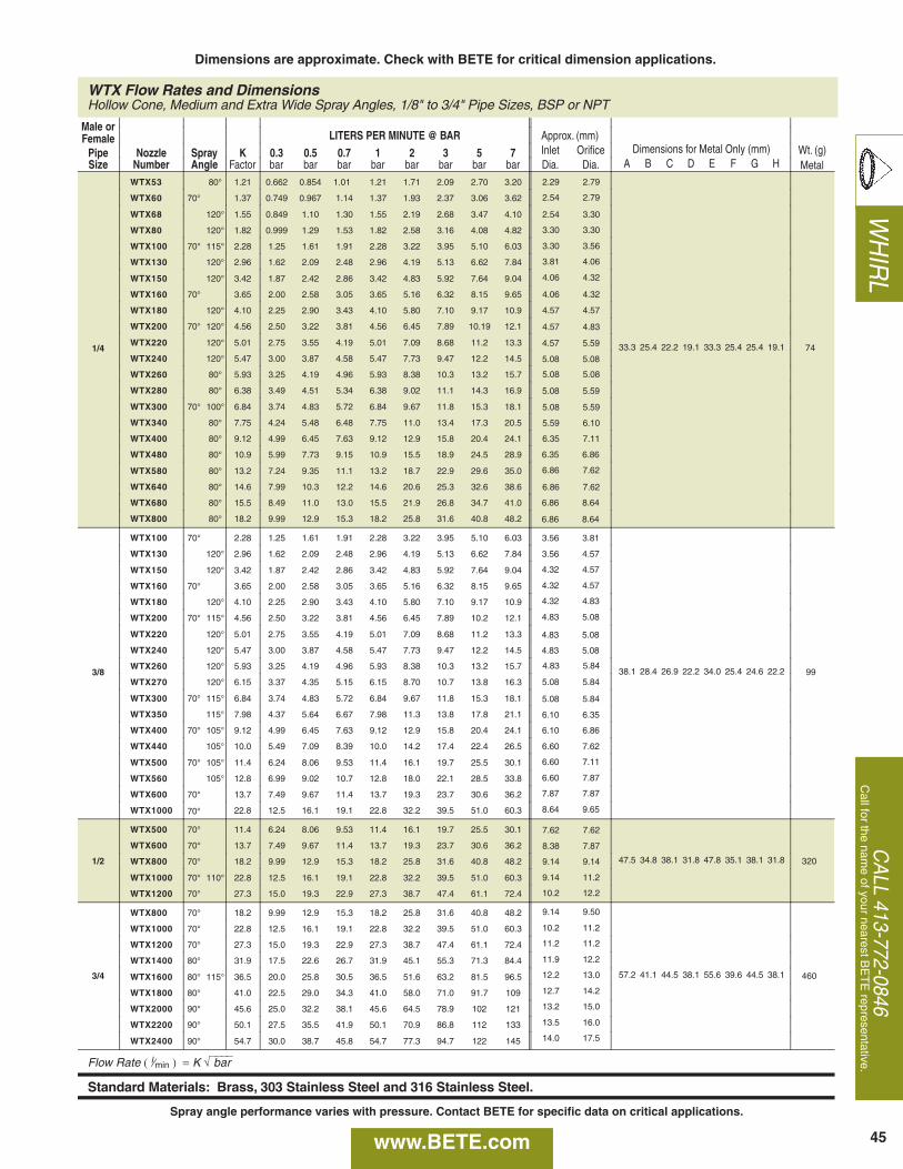
WH
IRL
CA
LL 413-772-0846C
all for the name of your nearest B
ET
E representative.
WTX Flow Rates and DimensionsHollow Cone, Medium and Extra Wide Spray Angles, 1/8" to 3/4" Pipe Sizes, BSP or NPT
Male orFemale LITERS PER MINUTE @ BAR Approx. (mm)
Pipe Nozzle Spray K 0.3 0.5 0.7 1 2 3 5 7 Inlet Orifice Dimensions for Metal Only (mm) Wt. (g)Size Number Angle Factor bar bar bar bar bar bar bar bar Dia. Dia. A B C D E F G H Metal
1/4
WTX53 80° 1.21 0.662 0.854 1.01 1.21 1.71 2.09 2.70 3.20
33.3 25.4 22.2 19.1 33.3 25.4 25.4 19.1 74
WTX60 70° 1.37 0.749 0.967 1.14 1.37 1.93 2.37 3.06 3.62
WTX68 120° 1.55 0.849 1.10 1.30 1.55 2.19 2.68 3.47 4.10
WTX80 120° 1.82 0.999 1.29 1.53 1.82 2.58 3.16 4.08 4.82
WTX100 70° 115° 2.28 1.25 1.61 1.91 2.28 3.22 3.95 5.10 6.03
WTX130 120° 2.96 1.62 2.09 2.48 2.96 4.19 5.13 6.62 7.84
WTX150 120° 3.42 1.87 2.42 2.86 3.42 4.83 5.92 7.64 9.04
WTX160 70° 3.65 2.00 2.58 3.05 3.65 5.16 6.32 8.15 9.65
WTX180 120° 4.10 2.25 2.90 3.43 4.10 5.80 7.10 9.17 10.9
WTX200 70° 120° 4.56 2.50 3.22 3.81 4.56 6.45 7.89 10.19 12.1
WTX220 120° 5.01 2.75 3.55 4.19 5.01 7.09 8.68 11.2 13.3
WTX240 120° 5.47 3.00 3.87 4.58 5.47 7.73 9.47 12.2 14.5
WTX260 80° 5.93 3.25 4.19 4.96 5.93 8.38 10.3 13.2 15.7
WTX280 80° 6.38 3.49 4.51 5.34 6.38 9.02 11.1 14.3 16.9
WTX300 70° 100° 6.84 3.74 4.83 5.72 6.84 9.67 11.8 15.3 18.1
WTX340 80° 7.75 4.24 5.48 6.48 7.75 11.0 13.4 17.3 20.5
WTX400 80° 9.12 4.99 6.45 7.63 9.12 12.9 15.8 20.4 24.1
WTX480 80° 10.9 5.99 7.73 9.15 10.9 15.5 18.9 24.5 28.9
WTX580 80° 13.2 7.24 9.35 11.1 13.2 18.7 22.9 29.6 35.0
WTX640 80° 14.6 7.99 10.3 12.2 14.6 20.6 25.3 32.6 38.6
WTX680 80° 15.5 8.49 11.0 13.0 15.5 21.9 26.8 34.7 41.0
WTX800 80° 18.2 9.99 12.9 15.3 18.2 25.8 31.6 40.8 48.2
3/8
WTX100 70° 2.28 1.25 1.61 1.91 2.28 3.22 3.95 5.10 6.03
38.1 28.4 26.9 22.2 34.0 25.4 24.6 22.2 99
WTX130 120° 2.96 1.62 2.09 2.48 2.96 4.19 5.13 6.62 7.84
WTX150 120° 3.42 1.87 2.42 2.86 3.42 4.83 5.92 7.64 9.04
WTX160 70° 3.65 2.00 2.58 3.05 3.65 5.16 6.32 8.15 9.65
WTX180 120° 4.10 2.25 2.90 3.43 4.10 5.80 7.10 9.17 10.9
WTX200 70° 115° 4.56 2.50 3.22 3.81 4.56 6.45 7.89 10.2 12.1
WTX220 120° 5.01 2.75 3.55 4.19 5.01 7.09 8.68 11.2 13.3
WTX240 120° 5.47 3.00 3.87 4.58 5.47 7.73 9.47 12.2 14.5
WTX260 120° 5.93 3.25 4.19 4.96 5.93 8.38 10.3 13.2 15.7
WTX270 120° 6.15 3.37 4.35 5.15 6.15 8.70 10.7 13.8 16.3
WTX300 70° 115° 6.84 3.74 4.83 5.72 6.84 9.67 11.8 15.3 18.1
WTX350 115° 7.98 4.37 5.64 6.67 7.98 11.3 13.8 17.8 21.1
WTX400 70° 105° 9.12 4.99 6.45 7.63 9.12 12.9 15.8 20.4 24.1
WTX440 105° 10.0 5.49 7.09 8.39 10.0 14.2 17.4 22.4 26.5
WTX500 70° 105° 11.4 6.24 8.06 9.53 11.4 16.1 19.7 25.5 30.1
WTX560 105° 12.8 6.99 9.02 10.7 12.8 18.0 22.1 28.5 33.8
WTX600 70° 13.7 7.49 9.67 11.4 13.7 19.3 23.7 30.6 36.2
WTX1000 70° 22.8 12.5 16.1 19.1 22.8 32.2 39.5 51.0 60.3
1/2
WTX500 70° 11.4 6.24 8.06 9.53 11.4 16.1 19.7 25.5 30.1
47.5 34.8 38.1 31.8 47.8 35.1 38.1 31.8 320
WTX600 70° 13.7 7.49 9.67 11.4 13.7 19.3 23.7 30.6 36.2
WTX800 70° 18.2 9.99 12.9 15.3 18.2 25.8 31.6 40.8 48.2
WTX1000 70° 110° 22.8 12.5 16.1 19.1 22.8 32.2 39.5 51.0 60.3
WTX1200 70° 27.3 15.0 19.3 22.9 27.3 38.7 47.4 61.1 72.4
3/4
WTX800 70° 18.2 9.99 12.9 15.3 18.2 25.8 31.6 40.8 48.2
57.2 41.1 44.5 38.1 55.6 39.6 44.5 38.1 460
WTX1000 70° 22.8 12.5 16.1 19.1 22.8 32.2 39.5 51.0 60.3
WTX1200 70° 27.3 15.0 19.3 22.9 27.3 38.7 47.4 61.1 72.4
WTX1400 80° 31.9 17.5 22.6 26.7 31.9 45.1 55.3 71.3 84.4
WTX1600 80° 115° 36.5 20.0 25.8 30.5 36.5 51.6 63.2 81.5 96.5
WTX1800 80° 41.0 22.5 29.0 34.3 41.0 58.0 71.0 91.7 109
WTX2000 90° 45.6 25.0 32.2 38.1 45.6 64.5 78.9 102 121
WTX2200 90° 50.1 27.5 35.5 41.9 50.1 70.9 86.8 112 133
WTX2400 90° 54.7 30.0 38.7 45.8 54.7 77.3 94.7 122 145
Flow Rate ( l⁄min ) = K √⎯⎯⎯⎯ bar
Standard Materials: Brass, 303 Stainless Steel and 316 Stainless Steel.
2.29 2.79
2.54 2.79
2.54 3.30
3.30 3.30
3.30 3.56
3.81 4.06
4.06 4.32
4.06 4.32
4.57 4.57
4.57 4.83
4.57 5.59
5.08 5.08
5.08 5.08
5.08 5.59
5.08 5.59
5.59 6.10
6.35 7.11
6.35 6.86
6.86 7.62
6.86 7.62
6.86 8.64
6.86 8.64
3.56 3.81
3.56 4.57
4.32 4.57
4.32 4.57
4.32 4.83
4.83 5.08
4.83 5.08
4.83 5.08
4.83 5.84
5.08 5.84
5.08 5.84
6.10 6.35
6.10 6.86
6.60 7.62
6.60 7.11
6.60 7.87
7.87 7.87
8.64 9.65
7.62 7.62
8.38 7.87
9.14 9.14
9.14 11.2
10.2 12.2
9.14 9.50
10.2 11.2
11.2 11.2
11.9 12.2
12.2 13.0
12.7 14.2
13.2 15.0
13.5 16.0
14.0 17.5
45
Dimensions are approximate. Check with BETE for critical dimension applications.
www.BETE.com
Spray angle performance varies with pressure. Contact BETE for specific data on critical applications.
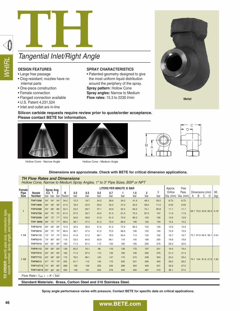
WH
IRL
TH
TH Flow Rates and DimensionsHollow Cone, Narrow to Medium Spray Angles, 1" to 3" Pipe Sizes, BSP or NPT
Female Spray Ang. LITERS PER MINUTE @ BAR Approx. Free
Pipe Nozzle 0.3 1 3 K 0.2 0.3 0.5 0.7 1 1.5 2 3 Orifice Pass. Dimensions (mm) Wt.Size Number bar bar bar Factor bar bar bar bar bar bar bar bar Dia. (mm) Dia. (mm) A B C D (kg)
1
THF1508 54° 54° 54° 34.2 15.3 18.7 24.2 28.6 34.2 41.9 48.3 59.2 8.73 8.73
58.7 79.2 50.8 26.9 0.18
THF1808 56° 56° 56° 41.0 18.3 22.5 29.0 34.3 41.0 50.2 58.0 71.0 9.53 9.53
THF2308 63° 66° 66° 52.4 23.4 28.7 37.1 43.9 52.4 64.2 74.1 90.8 11.1 11.1
THF2708 66° 70° 70° 61.5 27.5 33.7 43.5 51.5 61.5 75.4 87.0 107 11.9 11.9
THF3208 68° 72° 71° 72.9 32.6 39.9 51.6 61.0 72.9 89.3 103 126 13.9 13.9
THF 3808 68° 72° 71° 86.6 38.7 47.4 61.2 72.5 86.6 106 122 150 15.2 15.2
1 1/4
THF3210 66° 66° 66° 72.9 32.6 39.9 51.6 61.0 72.9 89.3 103 126 13.9 13.9
73.1 97.8 66.5 38.1 0.54
THF3810 68° 70° 70° 86.6 38.7 47.4 61.2 72.5 86.6 106 122 150 15.9 15.9
THF4110 73° 74° 74° 93.4 41.8 51.2 66.1 78.2 93.4 114 132 162 16.7 16.7
THF5210 79° 80° 80° 119 53.0 64.9 83.8 99.1 119 145 168 205 19.8 19.8
THF7010 83° 85° 85° 160 71.3 87.4 113 133 160 195 226 276 26.2 22.6
1 1/2
THF6112 58° 60° 60° 139 62.2 76.1 98 116 139 170 197 241 19.4 19.4
74.7 104 81.8 47.8 1.00
THF7012 63° 65° 65° 160 71.3 87.4 113 133 160 195 226 276 21.4 21.4
THF7712 63° 66° 66° 175 78.5 96.1 124 147 175 215 248 304 23.4 23.4
THF9012 67° 70° 70° 205 91.7 112 145 172 205 251 290 355 26.2 26.2
THF12712 75° 80° 80° 289 129 159 205 242 289 354 409 501 32.9 27.0
THF14512 80° 80° 83° 330 148 181 234 276 330 405 467 572 36.1 27.0
Flow Rate ( l⁄min ) = K √⎯⎯⎯⎯ bar
Standard Materials: Brass, Carbon Steel and 316 Stainless Steel.
Tangential Inlet/Right Angle
DESIGN FEATURES• Large free passage• Clog-resistant; nozzles have no
internal parts• One-piece construction• Female connection• Flanged connection available• U.S. Patent 4,231,524• Inlet and outlet are in-line
SPRAY CHARACTERISTICS• Patented geometry designed to give
the most uniform liquid distributionaround the periphery of the spray.
Spray pattern: Hollow ConeSpray angles: Narrow to MediumFlow rates: 15.3 to 2230 l/min
Hollow Cone - Narrow Angle Hollow Cone - Medium Angle
46
Metal
TO O
RD
ER:s
peci
fy p
ipe
size
, con
nect
ion
type
,no
zzle
num
ber,
spra
y an
gle,
and
mat
eria
l.
Silicon carbide requests require review prior to quote/order acceptance. Please contact BETE for information.
Dimensions are approximate. Check with BETE for critical dimension applications.
www.BETE.com
Spray angle performance varies with pressure. Contact BETE for specific data on critical applications.
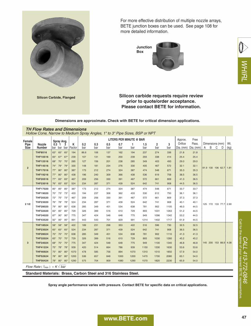
WH
IRL
CA
LL 413-772-0846C
all for the name of your nearest B
ET
E representative.
TH Flow Rates and DimensionsHollow Cone, Narrow to Medium Spray Angles, 1" to 3" Pipe Sizes, BSP or NPT
Female Spray Ang. LITERS PER MINUTE @ BAR Approx. Free
Pipe Nozzle 0.3 1 3 K 0.2 0.3 0.5 0.7 1 1.5 2 3 Orifice Pass. Dimensions (mm) Wt.Size Number bar bar bar Factor bar bar bar bar bar bar bar bar Dia. (mm) Dia. (mm) A B C D (kg)
2
THF8516 63° 65° 65° 194 86.6 106 137 162 194 237 274 336 21.8 21.8
91.9 130 106 62.7 1.81
THF10516 65° 67° 67° 239 107 131 169 200 239 293 338 414 25.4 25.4
THF12516 68° 70° 70° 285 127 156 201 238 285 349 403 493 29.0 29.0
THF14516 74° 79° 79° 330 148 181 234 276 330 405 467 572 32.1 32.1
THF17016 77° 80° 80° 387 173 212 274 324 387 474 548 671 35.3 35.3
THF19216 77° 80° 80° 438 196 240 309 366 438 536 619 758 38.5 36.5
THF20516 77° 83° 83° 467 209 256 330 391 467 572 661 809 41.3 36.5
THF23016 76° 83° 83° 524 234 287 371 439 524 642 741 908 44.5 36.5
2 1/2
THF17020 85° 85° 85° 387 173 212 274 324 387 474 548 671 33.7 33.7
125 172 133 77.7 2.90
THF19020 70° 73° 73° 433 194 237 306 362 433 530 612 750 36.1 36.1
THF20520 72° 75° 73° 467 209 256 330 391 467 572 661 809 37.3 37.3
THF23020 76° 78° 78° 524 234 287 371 439 524 642 741 908 40.1 40.1
THF28020 79° 80° 80° 638 285 349 451 534 638 781 902 1105 46.0 44.5
THF32020 83° 85° 85° 729 326 399 516 610 729 893 1031 1263 51.2 44.5
THF34020 87° 90° 90° 775 347 424 548 648 775 949 1096 1342 53.2 44.5
THF43520 92° 95° 95° 991 443 543 701 829 991 1214 1402 1717 61.9 44.5
3
THF18524 58° 58° 58° 422 189 231 298 353 422 516 596 730 32.5 32.5
145 200 153 88.9 4.08
THF23024 65° 65° 65° 524 234 287 371 439 524 642 741 908 36.5 36.5
THF28024 70° 70° 70° 638 285 349 451 534 638 781 902 1110 41.3 41.3
THF32024 65° 70° 70° 729 326 399 516 610 729 893 1030 1260 45.2 45.2
THF34024 68° 70° 70° 775 347 424 548 648 775 949 1100 1340 46.8 46.8
THF41224 75° 78° 78° 939 420 514 664 786 939 1150 1330 1630 53.6 53.6
THF46924 75° 80° 80° 1070 478 585 756 894 1070 1310 1510 1850 57.9 54.0
THF52624 78° 80° 80° 1200 536 657 848 1000 1200 1470 1700 2080 63.1 54.0
THF56424 78° 80° 80° 1290 575 704 909 1080 1290 1570 1820 2230 65.9 54.0
Flow Rate ( l⁄min ) = K √⎯⎯⎯⎯ bar
Standard Materials: Brass, Carbon Steel and 316 Stainless Steel.
47
Silicon Carbide, Flanged
For more effective distribution of multiple nozzle arrays,BETE junction boxes can be used. See page 108 formore detailed information.
JunctionBox
Silicon carbide requests require review prior to quote/order acceptance.
Please contact BETE for information.
Dimensions are approximate. Check with BETE for critical dimension applications.
www.BETE.com
Spray angle performance varies with pressure. Contact BETE for specific data on critical applications.
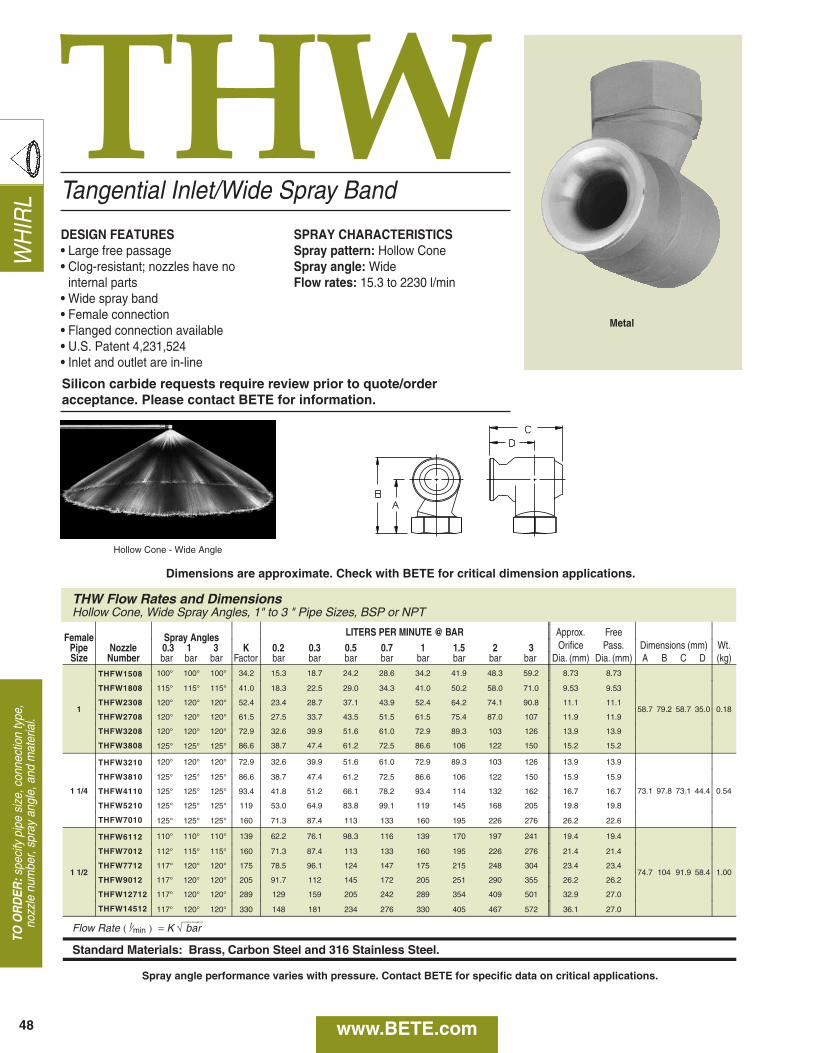
WH
IRL
THW
THW Flow Rates and DimensionsHollow Cone, Wide Spray Angles, 1" to 3 " Pipe Sizes, BSP or NPT
Female Spray Angles LITERS PER MINUTE @ BAR Approx. Free
Pipe Nozzle 0.3 1 3 K 0.2 0.3 0.5 0.7 1 1.5 2 3 Orifice Pass. Dimensions (mm) Wt.Size Number bar bar bar Factor bar bar bar bar bar bar bar bar Dia. (mm) Dia. (mm) A B C D (kg)
1
THFW1508 100° 100° 100° 34.2 15.3 18.7 24.2 28.6 34.2 41.9 48.3 59.2 8.73 8.73
58.7 79.2 58.7 35.0 0.18
THFW1808 115° 115° 115° 41.0 18.3 22.5 29.0 34.3 41.0 50.2 58.0 71.0 9.53 9.53
THFW2308 120° 120° 120° 52.4 23.4 28.7 37.1 43.9 52.4 64.2 74.1 90.8 11.1 11.1
THFW2708 120° 120° 120° 61.5 27.5 33.7 43.5 51.5 61.5 75.4 87.0 107 11.9 11.9
THFW3208 120° 120° 120° 72.9 32.6 39.9 51.6 61.0 72.9 89.3 103 126 13.9 13.9
THFW3808 125° 125° 125° 86.6 38.7 47.4 61.2 72.5 86.6 106 122 150 15.2 15.2
1 1/4
THFW3210 120° 120° 120° 72.9 32.6 39.9 51.6 61.0 72.9 89.3 103 126 13.9 13.9
73.1 97.8 73.1 44.4 0.54
THFW3810 125° 125° 125° 86.6 38.7 47.4 61.2 72.5 86.6 106 122 150 15.9 15.9
THFW4110 125° 125° 125° 93.4 41.8 51.2 66.1 78.2 93.4 114 132 162 16.7 16.7
THFW5210 125° 125° 125° 119 53.0 64.9 83.8 99.1 119 145 168 205 19.8 19.8
THFW7010 125° 125° 125° 160 71.3 87.4 113 133 160 195 226 276 26.2 22.6
1 1/2
THFW6112 110° 110° 110° 139 62.2 76.1 98.3 116 139 170 197 241 19.4 19.4
74.7 104 91.9 58.4 1.00
THFW7012 112° 115° 115° 160 71.3 87.4 113 133 160 195 226 276 21.4 21.4
THFW7712 117° 120° 120° 175 78.5 96.1 124 147 175 215 248 304 23.4 23.4
THFW9012 117° 120° 120° 205 91.7 112 145 172 205 251 290 355 26.2 26.2
THFW12712 117° 120° 120° 289 129 159 205 242 289 354 409 501 32.9 27.0
THFW14512 117° 120° 120° 330 148 181 234 276 330 405 467 572 36.1 27.0
Flow Rate ( l⁄min ) = K √⎯⎯⎯⎯ bar
Standard Materials: Brass, Carbon Steel and 316 Stainless Steel.
Tangential Inlet/Wide Spray Band
DESIGN FEATURES• Large free passage• Clog-resistant; nozzles have no
internal parts• Wide spray band• Female connection• Flanged connection available• U.S. Patent 4,231,524• Inlet and outlet are in-line
SPRAY CHARACTERISTICSSpray pattern: Hollow ConeSpray angle: WideFlow rates: 15.3 to 2230 l/min
Hollow Cone - Wide Angle
48
TO O
RD
ER:s
peci
fy p
ipe
size
, con
nect
ion
type
,no
zzle
num
ber,
spra
y an
gle,
and
mat
eria
l.
Metal
Silicon carbide requests require review prior to quote/orderacceptance. Please contact BETE for information.
Dimensions are approximate. Check with BETE for critical dimension applications.
www.BETE.com
Spray angle performance varies with pressure. Contact BETE for specific data on critical applications.
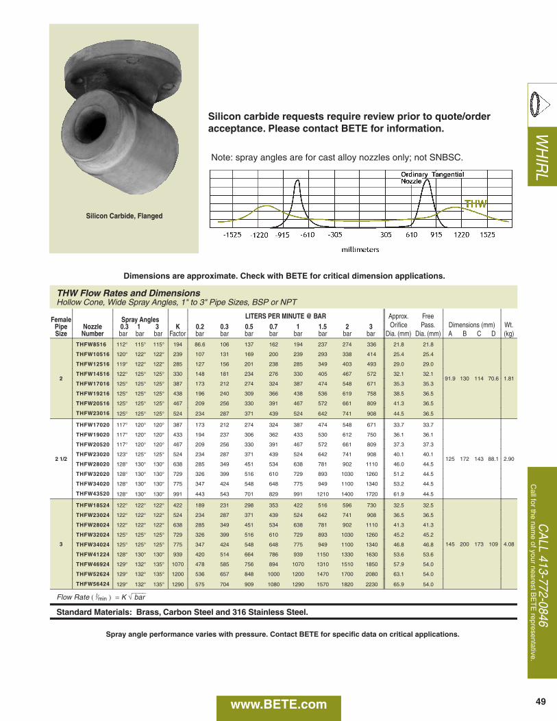
WH
IRL
CA
LL 413-772-0846C
all for the name of your nearest B
ET
E representative.
THW Flow Rates and DimensionsHollow Cone, Wide Spray Angles, 1" to 3" Pipe Sizes, BSP or NPT
Female Spray Angles LITERS PER MINUTE @ BAR Approx. Free
Pipe Nozzle 0.3 1 3 K 0.2 0.3 0.5 0.7 1 1.5 2 3 Orifice Pass. Dimensions (mm) Wt.Size Number bar bar bar Factor bar bar bar bar bar bar bar bar Dia. (mm) Dia. (mm) A B C D (kg)
2
THFW8516 112° 115° 115° 194 86.6 106 137 162 194 237 274 336 21.8 21.8
91.9 130 114 70.6 1.81
THFW10516 120° 122° 122° 239 107 131 169 200 239 293 338 414 25.4 25.4
THFW12516 119° 122° 122° 285 127 156 201 238 285 349 403 493 29.0 29.0
THFW14516 122° 125° 125° 330 148 181 234 276 330 405 467 572 32.1 32.1
THFW17016 125° 125° 125° 387 173 212 274 324 387 474 548 671 35.3 35.3
THFW19216 125° 125° 125° 438 196 240 309 366 438 536 619 758 38.5 36.5
THFW20516 125° 125° 125° 467 209 256 330 391 467 572 661 809 41.3 36.5
THFW23016 125° 125° 125° 524 234 287 371 439 524 642 741 908 44.5 36.5
2 1/2
THFW17020 117° 120° 120° 387 173 212 274 324 387 474 548 671 33.7 33.7
125 172 143 88.1 2.90
THFW19020 117° 120° 120° 433 194 237 306 362 433 530 612 750 36.1 36.1
THFW20520 117° 120° 120° 467 209 256 330 391 467 572 661 809 37.3 37.3
THFW23020 123° 125° 125° 524 234 287 371 439 524 642 741 908 40.1 40.1
THFW28020 128° 130° 130° 638 285 349 451 534 638 781 902 1110 46.0 44.5
THFW32020 128° 130° 130° 729 326 399 516 610 729 893 1030 1260 51.2 44.5
THFW34020 128° 130° 130° 775 347 424 548 648 775 949 1100 1340 53.2 44.5
THFW43520 128° 130° 130° 991 443 543 701 829 991 1210 1400 1720 61.9 44.5
3
THFW18524 122° 122° 122° 422 189 231 298 353 422 516 596 730 32.5 32.5
145 200 173 109 4.08
THFW23024 122° 122° 122° 524 234 287 371 439 524 642 741 908 36.5 36.5
THFW28024 122° 122° 122° 638 285 349 451 534 638 781 902 1110 41.3 41.3
THFW32024 125° 125° 125° 729 326 399 516 610 729 893 1030 1260 45.2 45.2
THFW34024 125° 125° 125° 775 347 424 548 648 775 949 1100 1340 46.8 46.8
THFW41224 128° 130° 130° 939 420 514 664 786 939 1150 1330 1630 53.6 53.6
THFW46924 129° 132° 135° 1070 478 585 756 894 1070 1310 1510 1850 57.9 54.0
THFW52624 129° 132° 135° 1200 536 657 848 1000 1200 1470 1700 2080 63.1 54.0
THFW56424 129° 132° 135° 1290 575 704 909 1080 1290 1570 1820 2230 65.9 54.0
Flow Rate ( l⁄min ) = K √⎯⎯⎯⎯ bar
Standard Materials: Brass, Carbon Steel and 316 Stainless Steel.
49
Silicon Carbide, Flanged
Silicon carbide requests require review prior to quote/orderacceptance. Please contact BETE for information.
Dimensions are approximate. Check with BETE for critical dimension applications.
www.BETE.com
Note: spray angles are for cast alloy nozzles only; not SNBSC.
Spray angle performance varies with pressure. Contact BETE for specific data on critical applications.
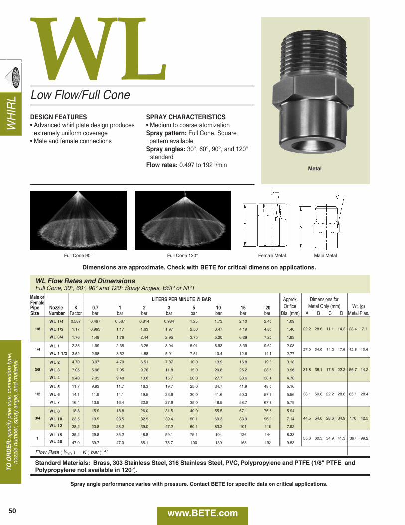
WH
IRL
WL
WL Flow Rates and DimensionsFull Cone, 30°, 60°, 90° and 120° Spray Angles, BSP or NPT
LITERS PER MINUTE @ BAR Approx. Dimensions for
Pipe Nozzle K 0.7 1 2 3 5 10 15 20 Orifice Metal Only (mm) Wt. (g)Size Number Factor bar bar bar bar bar bar bar bar Dia. (mm) A B C D Metal Plas.
1/8
WL 1/4 0.587 0.497 0.587 0.814 0.984 1.25 1.73 2.10 2.40 1.09
22.2 28.6 11.1 14.3 28.4 7.1WL 1/2 1.17 0.993 1.17 1.63 1.97 2.50 3.47 4.19 4.80 1.40
WL 3/4 1.76 1.49 1.76 2.44 2.95 3.75 5.20 6.29 7.20 1.83
1/4WL 1 2.35 1.99 2.35 3.25 3.94 5.01 6.93 8.39 9.60 2.08
27.0 34.9 14.2 17.5 42.5 10.6WL 1 1/2 3.52 2.98 3.52 4.88 5.91 7.51 10.4 12.6 14.4 2.77
3/8
WL 2 4.70 3.97 4.70 6.51 7.87 10.0 13.9 16.8 19.2 3.18
31.8 38.1 17.5 22.2 56.7 14.2WL 3 7.05 5.96 7.05 9.76 11.8 15.0 20.8 25.2 28.8 3.96
WL 4 9.40 7.95 9.40 13.0 15.7 20.0 27.7 33.6 38.4 4.78
1/2
WL 5 11.7 9.93 11.7 16.3 19.7 25.0 34.7 41.9 48.0 5.16
38.1 50.8 22.2 28.6 85.1 28.4WL 6 14.1 11.9 14.1 19.5 23.6 30.0 41.6 50.3 57.6 5.56
WL 7 16.4 13.9 16.4 22.8 27.6 35.0 48.5 58.7 67.2 5.79
3/4
WL 8 18.8 15.9 18.8 26.0 31.5 40.0 55.5 67.1 76.8 5.94
44.5 54.0 28.6 34.9 170 42.5WL 10 23.5 19.9 23.5 32.5 39.4 50.1 69.3 83.9 96.0 7.14
WL 12 28.2 23.8 28.2 39.0 47.2 60.1 83.2 101 115 7.92
1WL 15 35.2 29.8 35.2 48.8 59.1 75.1 104 126 144 8.33
55.6 60.3 34.9 41.3 397 99.2WL 20 47.0 39.7 47.0 65.1 78.7 100 139 168 192 9.53
Flow Rate ( l⁄min ) = K ( bar )0.47
Standard Materials: Brass, 303 Stainless Steel, 316 Stainless Steel, PVC, Polypropylene and PTFE (1/8" PTFE andPolypropylene not available in 120°).
Male orFemale
Low Flow/Full Cone
DESIGN FEATURES• Advanced whirl plate design produces
extremely uniform coverage• Male and female connections
SPRAY CHARACTERISTICS• Medium to coarse atomizationSpray pattern: Full Cone. Square pattern available
Spray angles: 30°, 60°, 90°, and 120°standard
Flow rates: 0.497 to 192 l/min
Full Cone 90° Full Cone 120° Female Metal Male Metal
50
Metal
TO O
RD
ER:s
peci
fy p
ipe
size
, con
nect
ion
type
,no
zzle
num
ber,
spra
y an
gle,
and
mat
eria
l.
Dimensions are approximate. Check with BETE for critical dimension applications.
www.BETE.com
Spray angle performance varies with pressure. Contact BETE for specific data on critical applications.
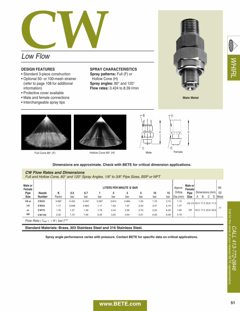
WH
IRL
CW
CW Flow Rates and DimensionsFull and Hollow Cone, 80° and 120° Spray Angles, 1/8" to 3/8" Pipe Sizes, BSP or NPT
Male orFemale LITERS PER MINUTE @ BAR Approx. Wt.
Pipe Nozzle K 0.5 0.7 1 2 3 5 10 15 Orifice Dimensions (mm) (g)Size Number Factor bar bar bar bar bar bar bar bar Dia.(mm) A B C Metal1/8 or CW25 0.587 0.424 0.497 0.587 0.814 0.984 1.25 1.73 2.10 1.14
711/4 CW50 1.17 0.848 0.993 1.17 1.63 1.97 2.50 3.47 4.19 1.37
or CW75 1.76 1.27 1.49 1.76 2.44 2.95 3.75 5.20 6.29 1.60
3/8 CW100 2.35 1.70 1.99 2.35 3.25 3.94 5.01 6.93 8.39 2.18
Flow Rate ( l⁄min ) = K ( bar )0.47
Standard Materials: Brass, 303 Stainless Steel and 316 Stainless Steel.
D
17.5 20.6 17.352.3
17.5 20.6 20.652.3
1/8-1/4
3/8
Male orFemale
PipeSize
Low Flow
DESIGN FEATURES• Standard 3-piece construction• Optional 50- or 100-mesh strainer
(refer to page 108 for additionalinformation)
• Protective cover available• Male and female connections• Interchangeable spray tips
SPRAY CHARACTERISTICSSpray patterns: Full (F) or Hollow Cone (H)
Spray angles: 80° and 120°Flow rates: 0.424 to 8.39 l/min
Full Cone 80° (F) Hollow Cone 80° (H)
51
Male Metal
CA
LL 413-772-0846C
all for the name of your nearest B
ET
E representative.
Male Female
Dimensions are approximate. Check with BETE for critical dimension applications.
www.BETE.com
Spray angle performance varies with pressure. Contact BETE for specific data on critical applications.
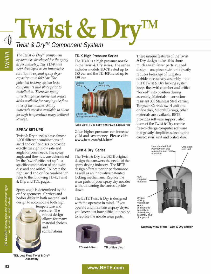
WH
IRL
www.BETE.com
TO O
RD
ER:s
peci
fy p
ipe
size
, con
nect
ion
type
,no
zzle
num
ber,
and
mat
eria
l.
The Twist & DryTM componentsystem was developed for the spraydryer industry. The TD‑K wasnext developed as an innovativesolution to expand spray dryercapacity up to 689 bar. Thepatented locking system lockscomponents into place prior toinstallation. There are manyinterchangeable swirls and orificedisks available for varying the flowrates of the nozzles. Manymaterials are also available to allowfor high temperature usage withoutleakage.
SPRAY SET-UPS
Twist & Dry nozzles have almost1,000 different combinations ofswirl and orifice discs to provideexactly the right flow rate andangle for your needs. The sprayangle and flow rate are determinedby the ”swirl/orifice set‑up”—aspecific combination of one swirldisc and one orifice. To locate theright swirl and orifice combinationrefer to the following TD‑K, Twist& Dry, and TDL pages.
Spray angle is determined by theorifice geometry. Carriers andbodies differ in both material anddesign to accomodate both high
temperature andpressure. The
robust designallows for manymaterial choicesandcombinations.
TDL Low Flow Twist & DryTM
Assembly
Twist & DryTM
TD-K High Pressure SeriesThe TD‑K is a high pressure nozzlein the Twist & Dry series. The seriesincludes models TD‑7K rated up to483 bar and the TD‑10K rated up to689 bar.
Often higher pressures can increaseyield and save money. Please visitwww.bete.com/td‑k.html.
Twist & Dry Series
The Twist & Dry is a BETE originaldesign that answers the needs of thespray drying industry. The BETEdesign offers superior performanceas well as an innovative patentedlocking mechanism. Replace thewear parts of your spray dry nozzleswithout turning the lances upsidedown.
The BETE Twist & Dry is designedwith the operator in mind. If youoperate and maintain a spray dryer,you know just how difficult it can beto replace the nozzle wear parts.
These unique features of the Twist& Dry design makes this choremuch easier: fewer parts; ruggeddesign—one piece swirl unit greatlyreduces breakage of tungstencarbide pieces; easy assembly—theBETE Twist & Dry locking systemkeeps the swirl chamber and orifice“locked” into position duringassembly; Materials— corrosion‑resistant 303 Stainless Steel carrier,Tungsten Carbide swirl unit andorifice disk, Viton® O‑rings, othermaterials are available. BETEprovides software support, also:users of the Twist & Dry receivefree‑of‑charge computer softwarethat greatly simplifies selecting thecorrect swirl unit and orifice disk.
Side View: TD-K body with PEEK backup ring
Uniquelockingmechanismkeepscomponentssecurely inplace duringassembly andchange out.
One pieceswirl unit
FDAcompliantmaterials
Unobstructed fluidpassages for clogresistance and reliableoperation.
Cutaway view of the Twist & Dry carrier
SiliconeO-ring
PEEKbackup ring
Viton® 90 O-ring also available
TD swirl disc TD orifice disc
Twist & DryTM Component System
52
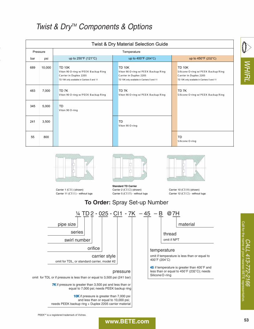
PEEKTM is a registered trademark of Victrex.
CA
LL 413-772-2166C
all for the name of your nearest B
ET
E representative.
www.BETE.com
Twist & DryTM Components & Options
Carrier 1 (CI1) (shown)
Carrier 11 (CI11) - without lugs
Carrier 2 (CI12) (shown)
Carrier 5 (CI15) - without lugs
Carrier 10 (CI10) (shown)
Carrier 12 (CI12) - without lugs
Standard TD Carrier
¼ TD 2 - 025 - CI1 - 7K – 45 – B @7H
pipe size
series
swirl number
orifice
carrier style
pressureomit for TDL or if pressure is less than or equal to 3,500 psi (241 bar)
7K7K if pressure is greater than 3,500 psi and less than or equal to 7,000 psi; needs PEEK backup ring
10K10K if pressure is greater than 7,000 psi and less than or equal to 10,000 psi;
needs PEEK backup ring + Duplex 2205 carrier material
omit for TDL, or standard carrier, model #2
material
threadomit if NPT
temperatureomit if temperature is less than or equal to 400˚F (204˚C)
4545 if temperature is greater than 400˚F and less than or equal to 450˚F (232˚C); needs Silicone O-ring
To Order: Spray Set-up Number
isprab
K01 DTK01 DTK01 DT000,01986 gniR pukcaB KEEP /w gnir-O enociliS gniR pukcaB KEEP /w gnir-O 09 notiV gniR pukcaB KEEP /w gnir-O 09 notiV
5022 xelpuD ni reirraC5022 xelpuD ni reirraC5022 xelpuD ni reirraC
11 dna 5 sreirraC ni elbaliava ylno K01 DT11 dna 5 sreirraC ni elbaliava ylno K01 DT11 dna 5 sreirraC ni elbaliava ylno K01 DT
K7 DTK7 DTK7 DT000,7384gniR pukcaB KEEP /w gnir-O enociliSgniR pukcaB KEEP /w gnir-O 09 notiVgniR pukcaB KEEP /w gnir-O 09 notiV
DT000,5543gnir-O 09 notiV
DT005,3142gnir-O 09 notiV
00855 DTgnir-O enociliS
ediuG noitceleS lairetaM yrD & tsiwT
F°054 ot pu )C°232( F°004 ot pu )C°402(
erusserP
)C°121( F°052 ot pu
erutarepmeT
53
WH
IRL
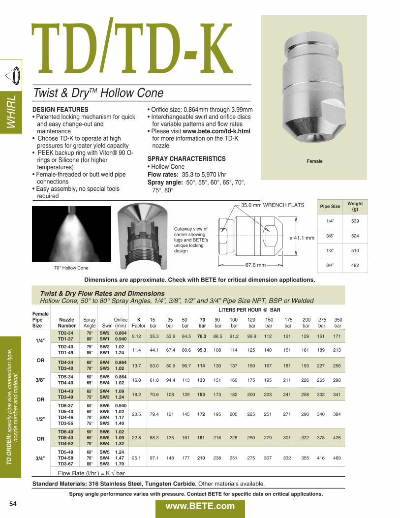
TD/TD‑KW
HIR
LTO
OR
DER
:spe
cify
pip
e si
ze, c
onne
ctio
n ty
pe,
nozz
le n
umbe
r and
mat
eria
l.
Twist & DryTM Hollow ConeDESIGN FEATURES• Patented locking mechanism for quick
and easy change-out and maintenance
• Choose TD-K to operate at highpressures for greater yield capacity
• PEEK backup ring with Viton® 90 O-rings or Silicone (for highertemperatures)
• Female-threaded or butt weld pipe connections
• Easy assembly, no special toolsrequired
• Orifice size: 0.864mm through 3.99mm• Interchangeable swirl and orifice discs
for variable patterns and flow rates• Please visit www.bete.com/td-k.html
for more information on the TD-Knozzle
SPRAY CHARACTERISTICS• Hollow ConeFlow rates: 35.3 to 5,970 l/hrSpray angle: 50°, 55°, 60°, 65°, 70°,
75°, 80°
Cutaway view ofcarrier showinglugs and BETE’sunique lockingdesign
70° Hollow Cone
54
LITERS PER HOUR @ BARFemalePipe Nozzle Spray Orifice K 15 35 50 70 90 100 120 150 175 200 275 350 Size Number Angle Swirl (mm) Factor bar bar bar bar bar bar bar bar bar bar bar bar
TD2-34 70° SW2 0.864TD1-37 80° SW1 0.940 9.12 35.3 53.9 64.5 76.3 86.5 91.2 99.9 112 121 129 151 171
TD2-40 75° SW2 1.02TD1-49 85° SW1 1.24 11.4 44.1 67.4 80.6 95.3 108 114 125 140 151 161 189 213
TD4-34 60° SW4 0.864TD3-40 70° SW3 1.02 13.7 53.0 80.9 96.7 114 130 137 150 167 181 193 227 256
TD5-34 50° SW5 0.864TD4-40 65° SW4 1.02 16.0 61.8 94.4 113 133 151 160 175 195 211 226 265 298
TD4-43 65° SW4 1.09TD3-49 75° SW3 1.24 18.2 70.6 108 129 153 173 182 200 223 241 258 302 341
TD6-37 50° SW6 0.940TD5-40 60° SW5 1.02 20.5 79.4 121 145 172 195 205 225 251 271 290 340 384TD4-46 70° SW4 1.17TD3-55 75° SW3 1.40
TD6-40 50° SW6 1.02TD5-43 60° SW5 1.09 22.8 88.3 135 161 191 216 228 250 279 301 322 378 426TD4-52 70° SW4 1.32
TD5-49 60° SW5 1.24TD4-58 70° SW4 1.47 25.1 97.1 148 177 210 238 251 275 307 332 355 416 469TD3-67 80° SW3 1.70
Flow Rate (l/hr ) = K √ bar
Standard Materials: 316 Stainless Steel, Tungsten Carbide. Other materials available.
Female
35.0 mm WRENCH FLATS
41.1 mm
67.6 mm
Dimensions are approximate. Check with BETE for critical dimension applications.
www.BETE.comSpray angle performance varies with pressure. Contact BETE for specific data on critical applications.
Twist & Dry Flow Rates and DimensionsHollow Cone, 50° to 80° Spray Angles, 1/4”, 3/8”, 1/2” and 3/4” Pipe Size NPT, BSP or Welded
1/4”
OR
3/8”
OR
1/2”
OR
3/4”
Pipe SizeWeight
(g)
1/4” 539
3/8” 524
1/2” 510
3/4” 482
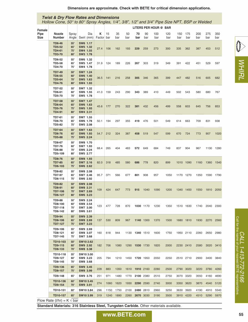
CA
LL 1-413-772-2166C
all for the name of your nearest B
ET
E representative.
WH
IRL
55
Dimensions are approximate. Check with BETE for critical dimension applications.
www.BETE.com
Twist & Dry Flow Rates and DimensionsHollow Cone, 50° to 80° Spray Angles, 1/4”, 3/8”, 1/2” and 3/4” Pipe Size NPT, BSP or Welded
LITERS PER HOUR @ BARFemalePipe Nozzle Spray Dia K 15 35 50 70 90 100 120 150 175 200 275 350Size Number Angle Swirl (mm) Factor bar bar bar bar bar bar bar bar bar bar bar bar
TD6-46 55° SW6 1.17TD5-52 65° SW5 1.32 27.4 106 162 193 229 259 273 300 335 362 387 453 512TD4-61 75° SW4 1.55TD3-70 80° SW3 1.78
TD6-52 55° SW6 1.32TD5-58 65° SW5 1.47 31.9 124 189 226 267 303 319 349 391 422 451 529 597TD4-70 75° SW4 1.78
TD7-49 50° SW7 1.24TD6-55 60° SW6 1.40TD5-64 70° SW5 1.63 36.5 141 216 258 305 346 365 399 447 482 516 605 682
TD4-76 80° SW4 1.93
TD7-52 50° SW7 1.32TD6-61 60° SW6 1.55 41.0 159 243 290 343 389 410 449 502 543 580 680 767TD5-70 70° SW5 1.78
TD7-58 55° SW7 1.47TD6-64 65° SW6 1.63 45.6 177 270 322 381 432 456 499 558 603 645 756 853TD5-76 75° SW5 1.93TD4-91 80° SW4 2.31
TD7-61 55° SW7 1.55TD6-70 65° SW6 1.78 50.1 194 297 355 419 476 501 549 614 663 709 831 938TD5-82 75° SW5 2.08
TD7-64 55° SW7 1.63TD6-76 65° SW6 1.93 54.7 212 324 387 458 519 547 599 670 724 773 907 1020TD5-88 75° SW5 2.24
TD8-67 50° SW8 1.70TD7-76 60° SW7 1.93TD6-88 70° SW6 2.24 68.4 265 404 483 572 649 684 749 837 904 967 1130 1280
TD5-109 80° SW5 2.77
TD8-76 50° SW8 1.93TD7-85 65° SW7 2.16 82.0 318 485 580 686 778 820 899 1010 1090 1160 1360 1540TD6-103 75° SW6 2.62
TD8-82 55° SW8 2.08TD7-97 65° SW7 2.46 95.7 371 566 677 801 908 957 1050 1170 1270 1350 1590 1790TD6-115 75° SW6 2.92
TD9-82 50° SW9 2.08TD8-91 60° SW8 2.31TD7-106 70° SW7 2.69 109 424 647 773 915 1040 1090 1200 1340 1450 1550 1810 2050
TD6-127 80° SW6 3.23
TD9-88 50° SW9 2.24TD8-100 60° SW8 2.54TD7-118 70° SW7 3.00 123 477 728 870 1030 1170 1230 1350 1510 1630 1740 2040 2300
TD6-142 80° SW6 3.61
TD9-94 55° SW9 2.39TD8-106 65° SW8 2.69 137 530 809 967 1140 1300 1370 1500 1680 1810 1930 2270 2560TD7-127 75° SW7 3.23
TD9-106 55° SW9 2.69TD8-121 65° SW8 3.07 160 618 944 1130 1340 1510 1600 1750 1950 2110 2260 2650 2980TD7-145 75° SW7 3.68
TD10-103 50° SW10 2.62TD9-115 60° SW9 2.92 182 706 1080 1290 1530 1730 1820 2000 2230 2410 2580 3020 3410TD8-133 70° SW8 3.38
TD10-118 55° SW10 3.00TD9-127 60° SW9 3.23 205 794 1210 1450 1720 1950 2050 2250 2510 2710 2900 3400 3840TD8-145 70° SW8 3.68
TD9-136 65° SW9 3.45TD8-157 75° SW8 3.99 228 883 1350 1610 1910 2160 2280 2500 2790 3020 3220 3780 4260
TD9-148 65° SW9 3.76 251 971 1480 1770 2100 2380 2510 2750 3070 3320 3550 4160 4690
TD10-136 60° SW10 3.45TD9-154 70° SW9 3.91 274 1060 1620 1930 2290 2590 2740 3000 3350 3620 3870 4540 5120
TD10-151 60° SW10 3.84 296 1150 1750 2100 2480 2810 2960 3250 3630 3920 4190 4910 5540
TD10-157 65° SW10 3.99 319 1240 1890 2260 2670 3030 3190 3500 3910 4220 4510 5290 5970
Flow Rate (l/hr) = K √ bar Standard Materials: 316 Stainless Steel, Tungsten Carbide. Other materials available.
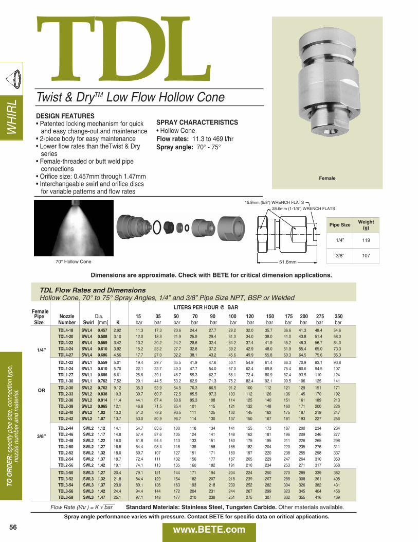
TDLTwist & DryTM Low Flow Hollow Cone
WH
IRL
TO O
RD
ER:s
peci
fy p
ipe
size
, con
nect
ion
type
,no
zzle
num
ber a
nd m
ater
ial.
DESIGN FEATURES• Patented locking mechanism for quick
and easy change-out and maintenance • 2-piece body for easy maintenance• Lower flow rates than theTwist & Dry
series• Female-threaded or butt weld pipe
connections• Orifice size: 0.457mm through 1.47mm• Interchangeable swirl and orifice discs
for variable patterns and flow rates
SPRAY CHARACTERISTICS• Hollow ConeFlow rates: 11.3 to 469 l/hrSpray angle: 70° - 75°
Female
70° Hollow Cone
56
15.9mm (5/8”) WRENCH FLATS
51.6mm
www.BETE.com
TDL Flow Rates and DimensionsHollow Cone, 70° to 75° Spray Angles, 1/4” and 3/8” Pipe Size NPT, BSP or Welded
Spray angle performance varies with pressure. Contact BETE for specific data on critical applications.
Pipe SizeWeight
(g)
1/4” 119
3/8” 107
28.6mm (1-1/8”) WRENCH FLATS
Dimensions are approximate. Check with BETE for critical dimension applications.
1/4”
OR
3/8”
LITERS PER HOUR @ BARFemalePipe Nozzle Dia. 15 35 50 70 90 100 120 150 175 200 275 350 Size Number Swirl [mm] K bar bar bar bar bar bar bar bar bar bar bar bar
TDL4-18 SWL4 0.457 2.92 11.3 17.3 20.6 24.4 27.7 29.2 32.0 35.7 36.6 41.3 48.4 54.6TDL4-20 SWL4 0.508 3.10 12.0 18.3 21.9 25.9 29.4 31.0 34.0 38.0 41.0 43.8 51.4 58.0TDL4-22 SWL4 0.559 3.42 13.2 20.2 24.2 28.6 32.4 34.2 37.4 41.9 45.2 48.3 56.7 64.0 TDL4-24 SWL4 0.610 3.92 15.2 23.2 27.7 32.8 37.2 39.2 42.9 48.0 51.9 55.4 65.0 73.3TDL4-27 SWL4 0.686 4.56 17.7 27.0 32.2 38.1 43.2 45.6 49.9 55.8 60.3 64.5 75.6 85.3
TDL1-22 SWL1 0.559 5.01 19.4 29.7 35.5 41.9 47.6 50.1 54.9 61.4 66.3 70.9 83.1 93.8TDL1-24 SWL1 0.610 5.70 22.1 33.7 40.3 47.7 54.0 57.0 62.4 69.8 75.4 80.6 94.5 107TDL1-27 SWL1 0.686 6.61 25.6 39.1 46.7 55.3 62.7 66.1 72.4 80.9 87.4 93.5 110 124TDL1-30 SWL1 0.762 7.52 29.1 44.5 53.2 62.9 71.3 75.2 82.4 92.1 99.5 106 125 141
TDL2-30 SWL2 0.762 9.12 35.3 53.9 64.5 76.3 86.5 91.2 100 112 121 129 151 171TDL2-33 SWL2 0.838 10.3 39.7 60.7 72.5 85.5 97.3 103 112 126 136 145 170 192 TDL2-36 SWL2 0.914 11.4 44.1 67.4 80.6 95.3 108 114 125 140 151 161 189 213TDL2-38 SWL2 0.965 12.1 46.8 71.5 85.4 101 115 121 132 148 160 171 200 226TDL2-40 SWL2 1.02 13.2 51.2 78.2 93.5 111 125 132 145 162 175 187 219 247TDL2-42 SWL2 1.07 13.7 53.0 80.9 96.7 114 130 137 150 167 181 193 227 256
TDL2-44 SWL2 1.12 14.1 54.7 83.6 100 118 134 141 155 173 187 200 234 264TDL2-46 SWL2 1.17 14.8 57.4 87.6 105 124 141 148 162 181 196 209 246 277TDL2-48 SWL2 1.22 16.0 61.8 94.4 113 133 151 160 175 195 211 226 265 298 TDL2-50 SWL2 1.27 16.6 64.4 98.4 118 139 158 166 182 204 220 235 276 311TDL2-52 SWL2 1.32 18.0 69.7 107 127 151 171 180 197 220 238 255 298 337TDL2-54 SWL2 1.37 18.7 72.4 111 132 156 177 187 205 229 247 264 310 350TDL2-56 SWL2 1.42 19.1 74.1 113 135 160 182 191 210 234 253 271 317 358
TDL3-50 SWL3 1.27 20.4 79.1 121 144 171 194 204 224 250 270 289 339 382TDL3-52 SWL3 1.32 21.8 84.4 129 154 182 207 218 239 267 288 308 361 408 TDL3-54 SWL3 1.37 23.0 89.1 136 163 193 218 230 252 282 304 326 382 431TDL3-56 SWL3 1.42 24.4 94.4 144 172 204 231 244 267 299 323 345 404 456TDL3-58 SWL3 1.47 25.1 97.1 148 177 210 238 251 275 307 332 355 416 469
Flow Rate (l/hr ) = K √ bar Standard Materials: Stainless Steel, Tungsten Carbide. Other materials available.
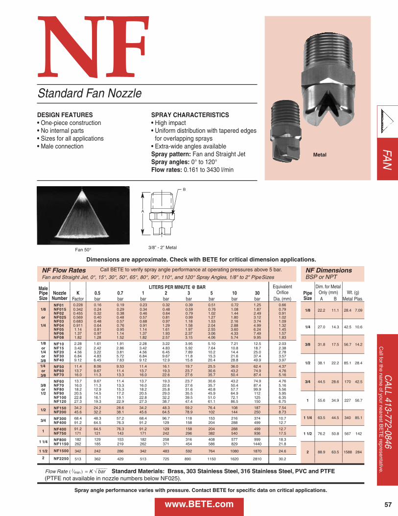
NFStandard Fan Nozzle
DESIGN FEATURES• One-piece construction• No internal parts• Sizes for all applications• Male connection
SPRAY CHARACTERISTICS• High impact• Uniform distribution with tapered edges
for overlapping sprays• Extra-wide angles availableSpray pattern: Fan and Straight JetSpray angles: 0° to 120°Flow rates: 0.161 to 3430 l/min
Fan 50°
Metal
NF Flow Rates NF DimensionsFan and Straight Jet, 0°, 15°, 30°, 50°, 65°, 80°, 90°, 110°, and 120° Spray Angles, 1/8" to 2" Pipe Sizes BSP or NPT
Male LITERS PER MINUTE @ BAR Equivalent Dim. for MetalPipe Nozzle K 0.5 0.7 1 2 3 5 10 30 Orifice Pipe Only (mm) Wt. (g)Size Number Factor bar bar bar bar bar bar bar bar Dia. (mm) Size A B Metal Plas.
NF01 0.228 0.16 0.19 0.23 0.32 0.39 0.51 0.72 1.25 0.661/8 22.2 11.1 28.4 7.091/8 NF015 0.342 0.24 0.29 0.34 0.48 0.59 0.76 1.08 1.87 0.79
NF02 0.455 0.32 0.38 0.46 0.64 0.79 1.02 1.44 2.49 0.91or NF025 0.569 0.40 0.48 0.57 0.81 0.99 1.27 1.80 3.12 1.02
NF03 0.683 0.48 0.57 0.68 0.97 1.18 1.53 2.16 3.74 1.09
1/4 27.0 14.3 42.5 10.61/4 NF04 0.911 0.64 0.76 0.91 1.29 1.58 2.04 2.88 4.99 1.32NF05 1.14 0.81 0.95 1.14 1.61 1.97 2.55 3.60 6.24 1.45NF06 1.37 0.97 1.14 1.37 1.93 2.37 3.06 4.33 7.49 1.57NF08 1.82 1.28 1.52 1.82 2.57 3.15 4.06 5.74 9.95 1.83
3/8 31.8 17.5 56.7 14.21/8 NF10 2.28 1.61 1.91 2.28 3.22 3.95 5.10 7.21 12.5 2.03or NF15 3.42 2.42 2.86 3.42 4.83 5.92 7.64 10.8 18.7 2.381/4 NF20 4.56 3.22 3.81 4.56 6.45 7.89 10.2 14.4 25.0 2.78or NF30 6.84 4.83 5.72 6.84 9.67 11.8 15.3 21.6 37.4 3.57
1/2 38.1 22.2 85.1 28.43/8 NF40 9.12 6.45 7.63 9.12 12.9 15.8 20.4 28.8 49.9 3.97
1/4 NF50 11.4 8.06 9.53 11.4 16.1 19.7 25.5 36.0 62.4 4.37or NF60 13.7 9.67 11.4 13.7 19.3 23.7 30.6 43.2 74.9 4.763/8 NF70 16.0 11.3 13.3 16.0 22.6 27.6 35.7 50.4 87.4 5.16
3/4 44.5 28.6 170 42.5NF60 13.7 9.67 11.4 13.7 19.3 23.7 30.6 43.2 74.9 4.763/8 NF70 16.0 11.3 13.3 16.0 22.6 27.6 35.7 50.4 87.4 5.16or NF80 18.2 12.9 15.3 18.2 25.8 31.6 40.8 57.7 99.9 5.561/2 NF90 20.5 14.5 17.2 20.5 29.0 35.5 45.9 64.9 112 5.95
1 55.6 34.9 227 56.7NF100 22.8 16.1 19.1 22.8 32.2 39.5 51.0 72.1 125 6.35NF120 27.3 19.3 22.9 27.3 38.7 47.4 61.1 86.5 150 6.75
1/2 NF150 34.2 24.2 28.6 34.2 48.3 59.2 76.4 108 187 7.54NF200 45.6 32.2 38.1 45.6 64.5 78.9 102 144 250 8.73
1 1/4 63.5 44.5 340 85.13/4 NF300 68.4 48.3 57.2 68.4 96.7 118 153 216 374 10.7
NF400 91.2 64.5 76.3 91.2 129 158 204 288 499 12.7
1 NF400 91.2 64.5 76.3 91.2 129 158 204 288 499 12.71 1/2 76.2 50.8 567 142NF750 171 121 143 171 242 296 382 540 936 17.5
1 1/4 NF800 182 129 153 182 258 316 408 577 999 18.3NF1150 262 185 219 262 371 454 586 829 1440 21.8
2 88.9 63.5 1588 2841 1/2 NF1500 342 242 286 342 483 592 764 1080 1870 24.6
2 NF2250 513 362 429 513 725 890 1150 1620 2810 30.2
Flow Rate ( l ⁄min ) = K √⎯⎯⎯⎯ bar Standard Materials: Brass, 303 Stainless Steel, 316 Stainless Steel, PVC and PTFE (PTFE not available in nozzle numbers below NF025).
Call BETE to verify spray angle performance at operating pressures above 5 bar.
3/8” - 2” Metal
B
A
FAN
CA
LL 413-772-0846C
all for the name of your nearest B
ET
E representative.
www.BETE.com
Dimensions are approximate. Check with BETE for critical dimension applications.
Spray angle performance varies with pressure. Contact BETE for specific data on critical applications.
57
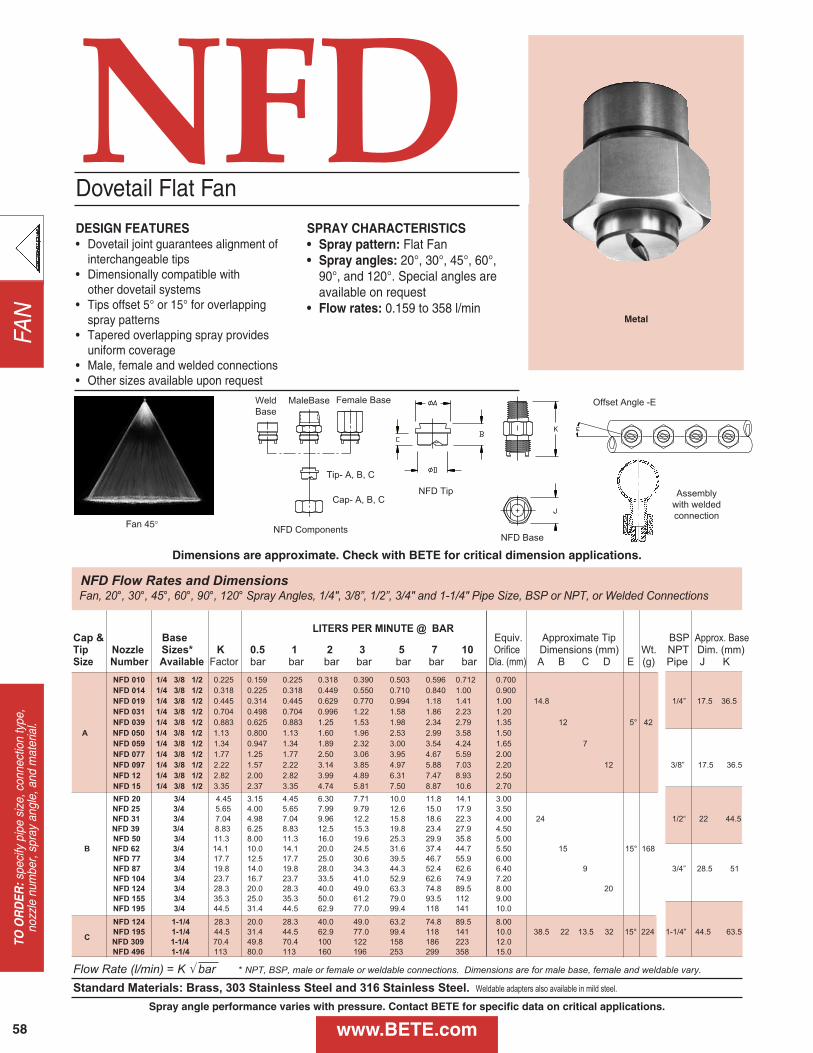
NFD ComponentsNFD Base
Offset Angle -EMaleBase
Cap- A, B, C
Tip- A, B, C
Weld
Base
Female Base
NFDDESIGN FEATURES• Dovetail joint guarantees alignment of
interchangeable tips• Dimensionally compatible with
other dovetail systems• Tips offset 5° or 15° for overlapping
spray patterns• Tapered overlapping spray provides
uniform coverage • Male, female and welded connections• Other sizes available upon request
SPRAY CHARACTERISTICS• Spray pattern: Flat Fan • Spray angles: 20°, 30°, 45°, 60°,
90°, and 120°. Special angles are available on request
• Flow rates: 0.159 to 358 l/min
Dovetail Flat Fan
Fan 45°
Metal
NFD Flow Rates and DimensionsFan, 20°, 30°, 45°, 60°, 90°, 120° Spray Angles, 1/4", 3/8”, 1/2”, 3/4" and 1-1/4" Pipe Size, BSP or NPT, or Welded Connections
LITERS PER MINUTE @ BARCap & Base Equiv. Approximate Tip BSP Approx. BaseTip Nozzle Sizes* K 0.5 1 2 3 5 7 10 Orifice Dimensions (mm) Wt. NPT Dim. (mm)Size Number Available Factor bar bar bar bar bar bar bar Dia. (mm) A B C D E (g) Pipe J K
NFD 010 1/4 3/8 1/2 0.225 0.159 0.225 0.318 0.390 0.503 0.596 0.712 0.700
NFD 014 1/4 3/8 1/2 0.318 0.225 0.318 0.449 0.550 0.710 0.840 1.00 0.900
NFD 019 1/4 3/8 1/2 0.445 0.314 0.445 0.629 0.770 0.994 1.18 1.41 1.00 14.8 1/4” 17.5 36.5
NFD 031 1/4 3/8 1/2 0.704 0.498 0.704 0.996 1.22 1.58 1.86 2.23 1.20
NFD 039 1/4 3/8 1/2 0.883 0.625 0.883 1.25 1.53 1.98 2.34 2.79 1.35 12 5° 42
A NFD 050 1/4 3/8 1/2 1.13 0.800 1.13 1.60 1.96 2.53 2.99 3.58 1.50
NFD 059 1/4 3/8 1/2 1.34 0.947 1.34 1.89 2.32 3.00 3.54 4.24 1.65 7
NFD 077 1/4 3/8 1/2 1.77 1.25 1.77 2.50 3.06 3.95 4.67 5.59 2.00
NFD 097 1/4 3/8 1/2 2.22 1.57 2.22 3.14 3.85 4.97 5.88 7.03 2.20 12 3/8” 17.5 36.5
NFD 12 1/4 3/8 1/2 2.82 2.00 2.82 3.99 4.89 6.31 7.47 8.93 2.50
NFD 15 1/4 3/8 1/2 3.35 2.37 3.35 4.74 5.81 7.50 8.87 10.6 2.70
NFD 20 3/4 4.45 3.15 4.45 6.30 7.71 10.0 11.8 14.1 3.00
NFD 25 3/4 5.65 4.00 5.65 7.99 9.79 12.6 15.0 17.9 3.50
NFD 31 3/4 7.04 4.98 7.04 9.96 12.2 15.8 18.6 22.3 4.00 24 1/2“ 22 44.5
NFD 39 3/4 8.83 6.25 8.83 12.5 15.3 19.8 23.4 27.9 4.50
NFD 50 3/4 11.3 8.00 11.3 16.0 19.6 25.3 29.9 35.8 5.00
B NFD 62 3/4 14.1 10.0 14.1 20.0 24.5 31.6 37.4 44.7 5.50 15 15° 168
NFD 77 3/4 17.7 12.5 17.7 25.0 30.6 39.5 46.7 55.9 6.00
NFD 87 3/4 19.8 14.0 19.8 28.0 34.3 44.3 52.4 62.6 6.40 9 3/4” 28.5 51
NFD 104 3/4 23.7 16.7 23.7 33.5 41.0 52.9 62.6 74.9 7.20
NFD 124 3/4 28.3 20.0 28.3 40.0 49.0 63.3 74.8 89.5 8.00 20
NFD 155 3/4 35.3 25.0 35.3 50.0 61.2 79.0 93.5 112 9.00
NFD 195 3/4 44.5 31.4 44.5 62.9 77.0 99.4 118 141 10.0
NFD 124 1-1/4 28.3 20.0 28.3 40.0 49.0 63.2 74.8 89.5 8.00
NFD 195 1-1/4 44.5 31.4 44.5 62.9 77.0 99.4 118 141 10.0 38.5 22 13.5 32 15° 224 1-1/4” 44.5 63.5C
NFD 309 1-1/4 70.4 49.8 70.4 100 122 158 186 223 12.0
NFD 496 1-1/4 113 80.0 113 160 196 253 299 358 15.0
Flow Rate (l/min) = K √ bar * NPT, BSP, male or female or weldable connections. Dimensions are for male base, female and weldable vary.
Standard Materials: Brass, 303 Stainless Steel and 316 Stainless Steel. Weldable adapters also available in mild steel.
NFD Tip
FAN
58
TO O
RD
ER:s
peci
fy p
ipe
size
, con
nect
ion
type
, no
zzle
num
ber,
spra
y an
gle,
and
mat
eria
l.
Dimensions are approximate. Check with BETE for critical dimension applications.
www.BETE.com
Assembly
with welded
connection
Spray angle performance varies with pressure. Contact BETE for specific data on critical applications.
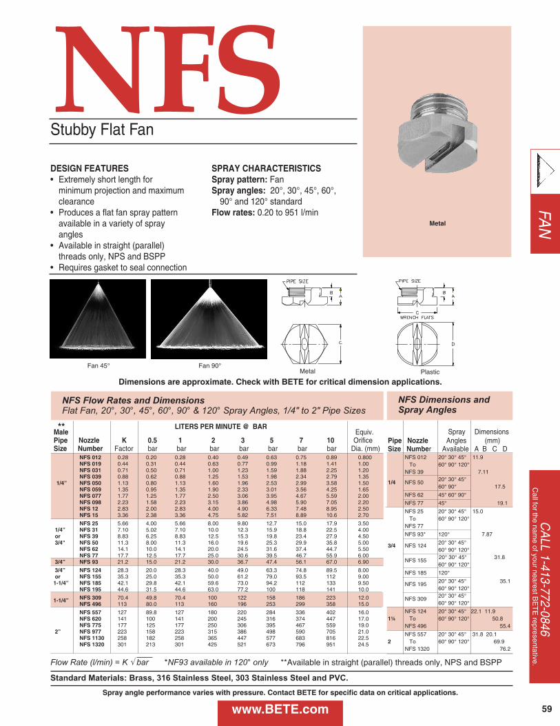
FAN
CA
LL 1-413-772-0846C
all for the name of your nearest B
ET
E representative.Flow Rate (l/min) = K √ bar *NF93 available in 120° only
Standard Materials: Brass, 316 Stainless Steel, 303 Stainless Steel and PVC.
DESIGN FEATURES• Extremely short length for
minimum projection and maximum clearance
• Produces a flat fan spray pattern available in a variety of spray angles
• Available in straight (parallel) threads only, NPS and BSPP
• Requires gasket to seal connection
SPRAY CHARACTERISTICSSpray pattern: FanSpray angles: 20°, 30°, 45°, 60°,
90° and 120° standardFlow rates: 0.20 to 951 l/min
Fan 45° Fan 90°Metal Plastic
Stubby Flat Fan
Metal
NFS Flow Rates and DimensionsFlat Fan, 20°, 30°, 45°, 60°, 90° & 120° Spray Angles, 1/4" to 2" Pipe Sizes
NFS Dimensions and Spray Angles
Spray DimensionsPipe Nozzle Angles (mm)Size Number Available A B C D
NFS 012 20° 30° 45° 11.9To 60° 90° 120°
NFS 39 7.11
1/4 NFS 50 20° 30° 45°60° 90° 17.5
NFS 62 45° 60° 90°
NFS 77 45° 19.1
NFS 25 20° 30° 45° 15.0To 60° 90° 120°
NFS 77
NFS 93* 120° 7.87
3/4 NFS 124 20° 30° 45°60° 90° 120°
NFS 155 20° 30° 45° 31.860° 90° 120°
NFS 185 120°
NFS 195 20° 30° 45° 35.160° 90° 120°
NFS 309 20° 30° 45° 60° 90° 120°
NFS 124 20° 30° 45° 22.1 11.91¼ To 60° 90° 120° 50.8
NFS 496 55.4
NFS 557 20° 30° 45° 31.8 20.12 To 60° 90° 120° 69.9
NFS 1320 76.2
LITERS PER MINUTE @ BARMale Equiv.Pipe Nozzle K 0.5 1 2 3 5 7 10 OrificeSize Number Factor bar bar bar bar bar bar bar Dia. (mm)
NFS 012 0.28 0.20 0.28 0.40 0.49 0.63 0.75 0.89 0.800NFS 019 0.44 0.31 0.44 0.63 0.77 0.99 1.18 1.41 1.00NFS 031 0.71 0.50 0.71 1.00 1.23 1.59 1.88 2.25 1.20NFS 039 0.88 0.62 0.88 1.25 1.53 1.98 2.34 2.79 1.35
1/4” NFS 050 1.13 0.80 1.13 1.60 1.96 2.53 2.99 3.58 1.50NFS 059 1.35 0.95 1.35 1.90 2.33 3.01 3.56 4.25 1.65NFS 077 1.77 1.25 1.77 2.50 3.06 3.95 4.67 5.59 2.00NFS 098 2.23 1.58 2.23 3.15 3.86 4.98 5.90 7.05 2.20NFS 12 2.83 2.00 2.83 4.00 4.90 6.33 7.48 8.95 2.50NFS 15 3.36 2.38 3.36 4.75 5.82 7.51 8.89 10.6 2.70
NFS 25 5.66 4.00 5.66 8.00 9.80 12.7 15.0 17.9 3.501/4” NFS 31 7.10 5.02 7.10 10.0 12.3 15.9 18.8 22.5 4.00or NFS 39 8.83 6.25 8.83 12.5 15.3 19.8 23.4 27.9 4.503/4" NFS 50 11.3 8.00 11.3 16.0 19.6 25.3 29.9 35.8 5.00
NFS 62 14.1 10.0 14.1 20.0 24.5 31.6 37.4 44.7 5.50NFS 77 17.7 12.5 17.7 25.0 30.6 39.5 46.7 55.9 6.00
3/4” NFS 93 21.2 15.0 21.2 30.0 36.7 47.4 56.1 67.0 6.90
3/4” NFS 124 28.3 20.0 28.3 40.0 49.0 63.3 74.8 89.5 8.00or NFS 155 35.3 25.0 35.3 50.0 61.2 79.0 93.5 112 9.001-1/4” NFS 185 42.1 29.8 42.1 59.6 73.0 94.2 112 133 9.50
NFS 195 44.6 31.5 44.6 63.0 77.2 100 118 141 10.0
NFS 309 70.4 49.8 70.4 100 122 158 186 223 12.01-1/4”NFS 496 113 80.0 113 160 196 253 299 358 15.0
NFS 557 127 89.8 127 180 220 284 336 402 16.0NFS 620 141 100 141 200 245 316 374 447 17.0NFS 775 177 125 177 250 306 395 467 559 19.0
2” NFS 977 223 158 223 315 386 498 590 705 21.0NFS 1130 258 182 258 365 447 577 683 816 22.5NFS 1320 301 213 301 425 521 673 796 951 24.5
**
**Available in straight (parallel) threads only, NPS and BSPP
Dimensions are approximate. Check with BETE for critical dimension applications.
NFS
www.BETE.comSpray angle performance varies with pressure. Contact BETE for specific data on critical applications.
59
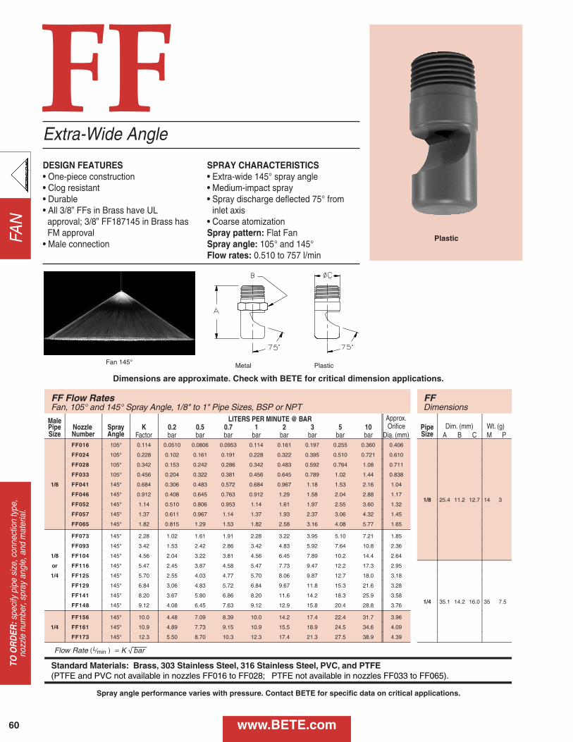
FAN
FF
FF Flow Rates FF Fan, 105° and 145° Spray Angle, 1/8" to 1" Pipe Sizes, BSP or NPT Dimensions
Male LITERS PER MINUTE @ BAR Approx. Pipe Nozzle Spray K 0.2 0.5 0.7 1 2 3 5 10 Orifice Pipe Dim. (mm) Wt. (g) Size Number Angle Factor bar bar bar bar bar bar bar bar Dia. (mm) Size A B C M P
1/8
FF016 105° 0.114 0.0510 0.0806 0.0953 0.114 0.161 0.197 0.255 0.360 0.406
1/8 25.4 11.2 12.7 14 3
FF024 105° 0.228 0.102 0.161 0.191 0.228 0.322 0.395 0.510 0.721 0.610
FF028 105° 0.342 0.153 0.242 0.286 0.342 0.483 0.592 0.764 1.08 0.711
FF033 105° 0.456 0.204 0.322 0.381 0.456 0.645 0.789 1.02 1.44 0.838
FF041 145° 0.684 0.306 0.483 0.572 0.684 0.967 1.18 1.53 2.16 1.04
FF046 145° 0.912 0.408 0.645 0.763 0.912 1.29 1.58 2.04 2.88 1.17
FF052 145° 1.14 0.510 0.806 0.953 1.14 1.61 1.97 2.55 3.60 1.32
FF057 145° 1.37 0.611 0.967 1.14 1.37 1.93 2.37 3.06 4.32 1.45
FF065 145° 1.82 0.815 1.29 1.53 1.82 2.58 3.16 4.08 5.77 1.65
FF073 145° 2.28 1.02 1.61 1.91 2.28 3.22 3.95 5.10 7.21 1.85
FF093 145° 3.42 1.53 2.42 2.86 3.42 4.83 5.92 7.64 10.8 2.36
1/8 FF104 145° 4.56 2.04 3.22 3.81 4.56 6.45 7.89 10.2 14.4 2.64
or FF116 145° 5.47 2.45 3.87 4.58 5.47 7.73 9.47 12.2 17.3 2.95
1/4 35.1 14.2 16.0 35 7.5
1/4 FF125 145° 5.70 2.55 4.03 4.77 5.70 8.06 9.87 12.7 18.0 3.18
FF129 145° 6.84 3.06 4.83 5.72 6.84 9.67 11.8 15.3 21.6 3.28
FF141 145° 8.20 3.67 5.80 6.86 8.20 11.6 14.2 18.3 25.9 3.58
FF148 145° 9.12 4.08 6.45 7.63 9.12 12.9 15.8 20.4 28.8 3.76
1/4
FF156 145° 10.0 4.48 7.09 8.39 10.0 14.2 17.4 22.4 31.7 3.96
FF161 145° 10.9 4.89 7.73 9.15 10.9 15.5 18.9 24.5 34.6 4.09
FF173 145° 12.3 5.50 8.70 10.3 12.3 17.4 21.3 27.5 38.9 4.39
Standard Materials: Brass, 303 Stainless Steel, 316 Stainless Steel, PVC, and PTFE (PTFE and PVC not available in nozzles FF016 to FF028; PTFE not available in nozzles FF033 to FF065).
Flow Rate ( L⁄min ) = K √ bar
Extra-Wide Angle
DESIGN FEATURES• One-piece construction• Clog resistant• Durable• All 3/8” FFs in Brass have UL approval; 3/8” FF187145 in Brass has FM approval
• Male connection
SPRAY CHARACTERISTICS• Extra-wide 145° spray angle• Medium-impact spray• Spray discharge deflected 75° from
inlet axis• Coarse atomizationSpray pattern: Flat FanSpray angle: 105° and 145°Flow rates: 0.510 to 757 l/min
Fan 145° Metal
60
Plastic
Plastic
TO O
RD
ER:s
peci
fy p
ipe
size
, con
nect
ion
type
, no
zzle
num
ber,
spra
y an
gle,
and
mat
eria
l.
Dimensions are approximate. Check with BETE for critical dimension applications.
www.BETE.com
Spray angle performance varies with pressure. Contact BETE for specific data on critical applications.
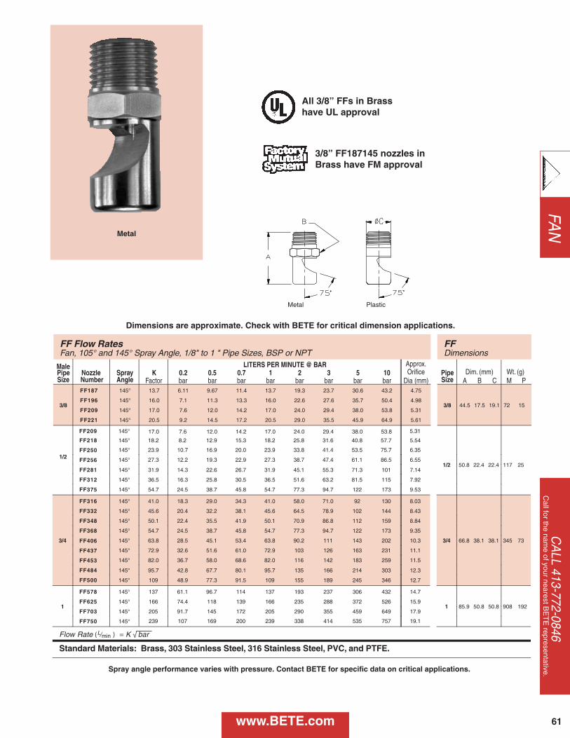
FAN
CA
LL 413-772-0846C
all for the name of your nearest B
ET
E representative.
61
Metal
Metal Plastic
All 3/8” FFs in Brass have UL approval
3/8” FF187145 nozzles inBrass have FM approval
FF Flow Rates FF Fan, 105° and 145° Spray Angle, 1/8" to 1 " Pipe Sizes, BSP or NPT Dimensions
Male LITERS PER MINUTE @ BAR Approx. Pipe Nozzle Spray K 0.2 0.5 0.7 1 2 3 5 10 Orifice Pipe Dim. (mm) Wt. (g) Size Number Angle Factor bar bar bar bar bar bar bar bar Dia (mm) Size A B C M P
3/8
FF187 145° 13.7 6.11 9.67 11.4 13.7 19.3 23.7 30.6 43.2 4.75
3/8 44.5 17.5 19.1 72 15 FF196 145° 16.0 7.1 11.3 13.3 16.0 22.6 27.6 35.7 50.4 4.98
FF209 145° 17.0 7.6 12.0 14.2 17.0 24.0 29.4 38.0 53.8 5.31
FF221 145° 20.5 9.2 14.5 17.2 20.5 29.0 35.5 45.9 64.9 5.61
1/2
FF218 145° 18.2 8.2 12.9 15.3 18.2 25.8 31.6 40.8 57.7 5.54
1/2 50.8 22.4 22.4 117 25
FF250 145° 23.9 10.7 16.9 20.0 23.9 33.8 41.4 53.5 75.7 6.35
FF256 145° 27.3 12.2 19.3 22.9 27.3 38.7 47.4 61.1 86.5 6.55
FF281 145° 31.9 14.3 22.6 26.7 31.9 45.1 55.3 71.3 101 7.14
FF312 145° 36.5 16.3 25.8 30.5 36.5 51.6 63.2 81.5 115 7.92
FF375 145° 54.7 24.5 38.7 45.8 54.7 77.3 94.7 122 173 9.53
3/4
FF316 145° 41.0 18.3 29.0 34.3 41.0 58.0 71.0 92 130 8.03
3/4 66.8 38.1 38.1 345 73
FF332 145° 45.6 20.4 32.2 38.1 45.6 64.5 78.9 102 144 8.43
FF348 145° 50.1 22.4 35.5 41.9 50.1 70.9 86.8 112 159 8.84
FF368 145° 54.7 24.5 38.7 45.8 54.7 77.3 94.7 122 173 9.35
FF406 145° 63.8 28.5 45.1 53.4 63.8 90.2 111 143 202 10.3
FF437 145° 72.9 32.6 51.6 61.0 72.9 103 126 163 231 11.1
FF453 145° 82.0 36.7 58.0 68.6 82.0 116 142 183 259 11.5
FF484 145° 95.7 42.8 67.7 80.1 95.7 135 166 214 303 12.3
FF500 145° 109 48.9 77.3 91.5 109 155 189 245 346 12.7
1
FF578 145° 137 61.1 96.7 114 137 193 237 306 432 14.7
1 85.9 50.8 50.8 908 192 FF625 145° 166 74.4 118 139 166 235 288 372 526 15.9
FF703 145° 205 91.7 145 172 205 290 355 459 649 17.9
FF750 145° 239 107 169 200 239 338 414 535 757 19.1
Flow Rate ( L⁄min ) = K √ bar
Standard Materials: Brass, 303 Stainless Steel, 316 Stainless Steel, PVC, and PTFE.
FF209 145° 5.31 17.0 7.6 12.0 14.2 17.0 24.0 29.4 38.0 53.8
Dimensions are approximate. Check with BETE for critical dimension applications.
www.BETE.com
Spray angle performance varies with pressure. Contact BETE for specific data on critical applications.
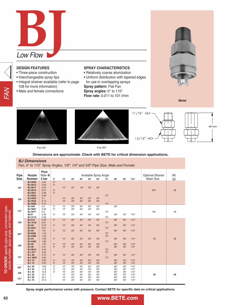
FAN
62
TO O
RD
ER:s
peci
fy p
ipe
size
, con
nect
ion
type
, no
zzle
num
ber,
spra
y an
gle,
and
mat
eria
l.
Low Flow
DESIGN FEATURES• Three-piece construction• Interchangeable spray tips• Integral strainer available (refer to page 108 for more information)
• Male and female connections
SPRAY CHARACTERISTICS• Relatively coarse atomization• Uniform distribution with tapered edges
for use in overlapping spraysSpray pattern: Flat FanSpray angles: 0° to 110°Flow rate: 0.011 to 101 l/min
Fan 50° Fan 80°
Metal
BJ DimensionsFan, 0° to 110° Spray Angles, 1/8", 1/4" and 3/8" Pipe Size, Male and Female
48 mm
Flow Pipe Nozzle Rate @ Available Spray Angle Optional Strainer Wt.Size Number 3 bar 0° 15° 25° 40° 50° 65° 73° 80° 95° 110° Mesh Size (g)
BJ 0009 0.04 0°BJ 0012 0.05 0°BJ 0017 0.07 15° 25° 40° 50° 65°BJ 0019 0.07 0° 200 28BJ 0021 0.08 0°B J 0023 0.09 73°BJ 0025 0.1 15° 25° 40° 50° 65°BJ 0033 0.13 15° 25° 40° 50° 65°BJ 0039 0.15 73°BJ 005 0.2 0° 15° 25° 40° 50° 65° 80°BJ 0067 0.26 0° 15° 25° 40° 50° 65°BJ 0077 0.3 73° 100 28BJ 01 0.39 0° 15° 25° 40° 50° 65° 80° 95° 110°BJ 0116 0.46 73°BJ 015 0.59 0° 15° 25° 40° 50° 65° 80° 95° 110°BJ 0154 0.61 73°BJ 02 0.79 0° 15° 25° 40° 50° 65° 80° 95° 110°BJ 0231 0.91 73°BJ 03 1.81 0° 15° 25° 40° 50° 65° 80° 95° 110°BJ 0308 1.22 73°BJ 0385 1.52 73°BJ 04 1.58 0° 15° 25° 40° 50° 65° 80° 95° 110° 50 28BJ 0462 1.82 73°BJ 05 1.97 0° 15° 25° 40° 50° 65° 80° 95° 110°BJ 06 2.37 0° 15° 25° 40° 50° 65° 80° 95° 110°BJ 0616 2.43 73°B J 077 3.04 73°B J 08 3.16 0° 15° 25° 40° 50° 65° 80° 95° 110°B J 0924 3.65 73°B J 10 3.95 0° 15° 25° 40° 50° 65° 80° 95° 110°B J 15 5.92 0° 15° 25° 40° 50° 65° 80° 95° 110°
B J 20 7.89 0° 15° 25° 40° 50° 65° 80° 95° 110°B J 30 11.8 0° 15° 25° 40° 50° 65° 80° 95° 110°B J 40 15.8 0° 15° 25° 40° 50° 65° 80° 95° 110°B J 50 19.7 15° 25° 40° 50° 65° 80° 95° 110° 50 28B J 60 23.7 15° 25° 40° 50° 65° 80° 95° 110°B J 70 27.6 15° 25° 40° 50° 65° 80° 95° 110°
Dimensions are approximate. Check with BETE for critical dimension applications.
BJ
www.BETE.com
1/8”
OR
1/4”
OR
3/8”
OR
1/2”
3/8”
OR
1/2”
Spray angle performance varies with pressure. Contact BETE for specific data on critical applications.
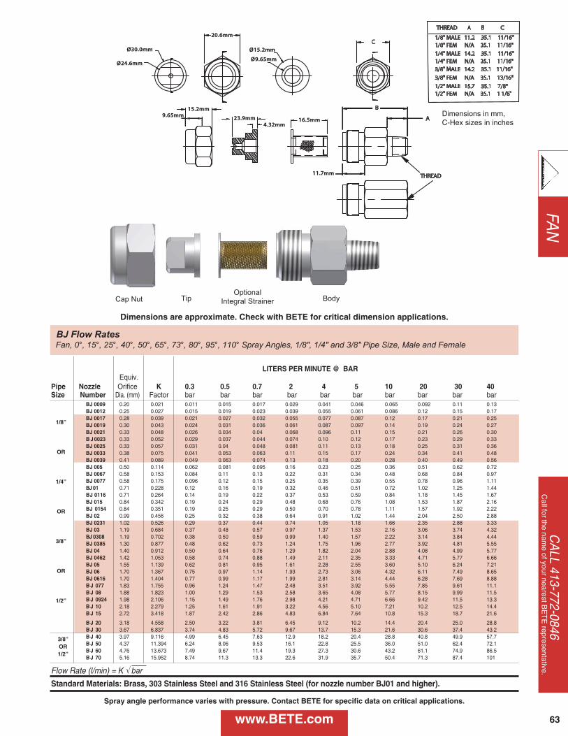
TipCap Nut Body
FAN
CA
LL 413-772-0846C
all for the name of your nearest B
ET
E representative.
63
BJ Flow RatesFan, 0°, 15°, 25°, 40°, 50°, 65°, 73°, 80°, 95°, 110° Spray Angles, 1/8", 1/4" and 3/8" Pipe Size, Male and Female
Dimensions in mm, C-Hex sizes in inches
Dimensions are approximate. Check with BETE for critical dimension applications.
www.BETE.com
Spray angle performance varies with pressure. Contact BETE for specific data on critical applications.
Optional
Integral Strainer
LITERS PER MINUTE @ BAREquiv.
Pipe Nozzle Orifice K 0.3 0.5 0.7 2 4 5 10 20 30 40Size Number Dia. (mm) Factor bar bar bar bar bar bar bar bar bar bar
BJ 0009 0.20 0.021 0.011 0.015 0.017 0.029 0.041 0.046 0.065 0.092 0.11 0.13BJ 0012 0.25 0.027 0.015 0.019 0.023 0.039 0.055 0.061 0.086 0.12 0.15 0.17BJ 0017 0.28 0.039 0.021 0.027 0.032 0.055 0.077 0.087 0.12 0.17 0.21 0.25BJ 0019 0.30 0.043 0.024 0.031 0.036 0.061 0.087 0.097 0.14 0.19 0.24 0.27BJ 0021 0.33 0.048 0.026 0.034 0.04 0.068 0.096 0.11 0.15 0.21 0.26 0.30B J 0023 0.33 0.052 0.029 0.037 0.044 0.074 0.10 0.12 0.17 0.23 0.29 0.33BJ 0025 0.33 0.057 0.031 0.04 0.048 0.081 0.11 0.13 0.18 0.25 0.31 0.36BJ 0033 0.38 0.075 0.041 0.053 0.063 0.11 0.15 0.17 0.24 0.34 0.41 0.48BJ 0039 0.41 0.089 0.049 0.063 0.074 0.13 0.18 0.20 0.28 0.40 0.49 0.56BJ 005 0.50 0.114 0.062 0.081 0.095 0.16 0.23 0.25 0.36 0.51 0.62 0.72BJ 0067 0.58 0.153 0.084 0.11 0.13 0.22 0.31 0.34 0.48 0.68 0.84 0.97BJ 0077 0.58 0.175 0.096 0.12 0.15 0.25 0.35 0.39 0.55 0.78 0.96 1.11BJ 01 0.71 0.228 0.12 0.16 0.19 0.32 0.46 0.51 0.72 1.02 1.25 1.44BJ 0116 0.71 0.264 0.14 0.19 0.22 0.37 0.53 0.59 0.84 1.18 1.45 1.67BJ 015 0.84 0.342 0.19 0.24 0.29 0.48 0.68 0.76 1.08 1.53 1.87 2.16BJ 0154 0.84 0.351 0.19 0.25 0.29 0.50 0.70 0.78 1.11 1.57 1.92 2.22BJ 02 0.99 0.456 0.25 0.32 0.38 0.64 0.91 1.02 1.44 2.04 2.50 2.88BJ 0231 1.02 0.526 0.29 0.37 0.44 0.74 1.05 1.18 1.66 2.35 2.88 3.33BJ 03 1.19 0.684 0.37 0.48 0.57 0.97 1.37 1.53 2.16 3.06 3.74 4.32BJ 0308 1.19 0.702 0.38 0.50 0.59 0.99 1.40 1.57 2.22 3.14 3.84 4.44BJ 0385 1.30 0.877 0.48 0.62 0.73 1.24 1.75 1.96 2.77 3.92 4.81 5.55BJ 04 1.40 0.912 0.50 0.64 0.76 1.29 1.82 2.04 2.88 4.08 4.99 5.77BJ 0462 1.42 1.053 0.58 0.74 0.88 1.49 2.11 2.35 3.33 4.71 5.77 6.66BJ 05 1.55 1.139 0.62 0.81 0.95 1.61 2.28 2.55 3.60 5.10 6.24 7.21BJ 06 1.70 1.367 0.75 0.97 1.14 1.93 2.73 3.06 4.32 6.11 7.49 8.65BJ 0616 1.70 1.404 0.77 0.99 1.17 1.99 2.81 3.14 4.44 6.28 7.69 8.88B J 077 1.83 1.755 0.96 1.24 1.47 2.48 3.51 3.92 5.55 7.85 9.61 11.1B J 08 1.88 1.823 1.00 1.29 1.53 2.58 3.65 4.08 5.77 8.15 9.99 11.5B J 0924 1.98 2.106 1.15 1.49 1.76 2.98 4.21 4.71 6.66 9.42 11.5 13.3B J 10 2.18 2.279 1.25 1.61 1.91 3.22 4.56 5.10 7.21 10.2 12.5 14.4B J 15 2.72 3.418 1.87 2.42 2.86 4.83 6.84 7.64 10.8 15.3 18.7 21.6
B J 20 3.18 4.558 2.50 3.22 3.81 6.45 9.12 10.2 14.4 20.4 25.0 28.8B J 30 3.67 6.837 3.74 4.83 5.72 9.67 13.7 15.3 21.6 30.6 37.4 43.2B J 40 3.97 9.116 4.99 6.45 7.63 12.9 18.2 20.4 28.8 40.8 49.9 57.7B J 50 4.37 11.394 6.24 8.06 9.53 16.1 22.8 25.5 36.0 51.0 62.4 72.1B J 60 4.76 13.673 7.49 9.67 11.4 19.3 27.3 30.6 43.2 61.1 74.9 86.5B J 70 5.16 15.952 8.74 11.3 13.3 22.6 31.9 35.7 50.4 71.3 87.4 101
Flow Rate (l/min) = K √ barStandard Materials: Brass, 303 Stainless Steel and 316 Stainless Steel (for nozzle number BJ01 and higher).
1/8”
OR
1/4”
OR
3/8”
OR
1/2”
3/8”OR1/2”
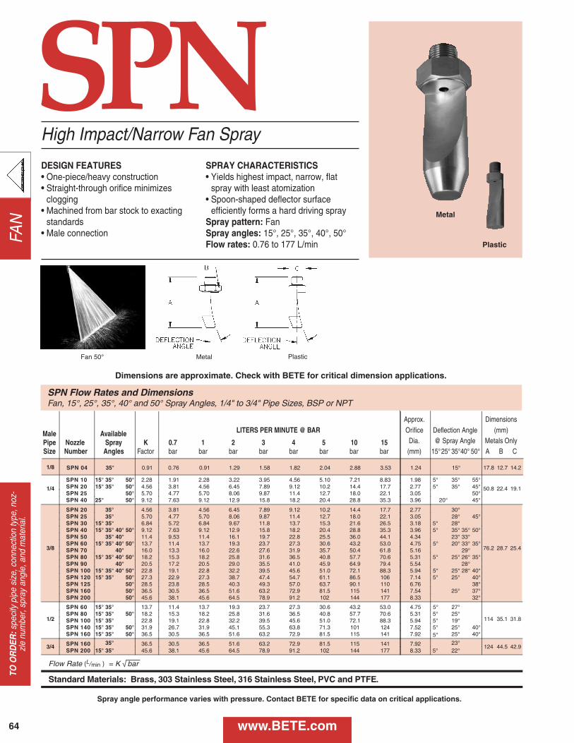
FAN
64
TO O
RD
ER:s
peci
fy p
ipe
size
, con
nect
ion
type
, noz
-zl
e nu
mbe
r, sp
ray
angl
e, a
nd m
ater
ial.
SPN
SPN Flow Rates and Dimensions Fan, 15°, 25°, 35°, 40° and 50° Spray Angles, 1/4" to 3/4" Pipe Sizes, BSP or NPT
Approx. Dimensions
Male Available LITERS PER MINUTE @ BAR Orifice Deflection Angle (mm)
Pipe Nozzle Spray K 0.7 1 2 3 4 5 10 15 Dia. @ Spray Angle Metals Only Size Number Angles Factor bar bar bar bar bar bar bar bar (mm) 15° 25° 35° 40° 50° A B C
1/4
SPN 10 15° 35° 50° 2.28 1.91 2.28 3.22 3.95 4.56 5.10 7.21 8.83 1.98 5° 35° 55°
50.8 22.4 19.1 SPN 20 15° 35° 50° 4.56 3.81 4.56 6.45 7.89 9.12 10.2 14.4 17.7 2.77 5° 35° 45° SPN 25 50° 5.70 4.77 5.70 8.06 9.87 11.4 12.7 18.0 22.1 3.05 50° SPN 40 25° 50° 9.12 7.63 9.12 12.9 15.8 18.2 20.4 28.8 35.3 3.96 20° 45°
3/8
SPN 20 35° 4.56 3.81 4.56 6.45 7.89 9.12 10.2 14.4 17.7 2.77 30°
76.2 28.7 25.4
SPN 25 35° 5.70 4.77 5.70 8.06 9.87 11.4 12.7 18.0 22.1 3.05 28° 45° SPN 30 15° 35° 6.84 5.72 6.84 9.67 11.8 13.7 15.3 21.6 26.5 3.18 5° 28° SPN 40 15° 35° 40° 50° 9.12 7.63 9.12 12.9 15.8 18.2 20.4 28.8 35.3 3.96 5° 35° 35° 50° SPN 50 35° 40° 11.4 9.53 11.4 16.1 19.7 22.8 25.5 36.0 44.1 4.34 23° 33° SPN 60 15° 35° 40° 50° 13.7 11.4 13.7 19.3 23.7 27.3 30.6 43.2 53.0 4.75 5° 20° 33° 35° SPN 70 40° 16.0 13.3 16.0 22.6 27.6 31.9 35.7 50.4 61.8 5.16 29° SPN 80 15° 35° 40° 50° 18.2 15.3 18.2 25.8 31.6 36.5 40.8 57.7 70.6 5.31 5° 25° 26° 35° SPN 90 40° 20.5 17.2 20.5 29.0 35.5 41.0 45.9 64.9 79.4 5.54 28° SPN 100 15° 35° 40° 50° 22.8 19.1 22.8 32.2 39.5 45.6 51.0 72.1 88.3 5.94 5° 25° 28° 40° SPN 120 15° 35° 50° 27.3 22.9 27.3 38.7 47.4 54.7 61.1 86.5 106 7.14 5° 25° 40° SPN 125 50° 28.5 23.8 28.5 40.3 49.3 57.0 63.7 90.1 110 6.76 38° SPN 160 50° 36.5 30.5 36.5 51.6 63.2 72.9 81.5 115 141 7.54 37° SPN 200 50° 45.6 38.1 45.6 64.5 78.9 91.2 102 144 177 8.33 32°
1/2
SPN 60 15° 35° 13.7 11.4 13.7 19.3 23.7 27.3 30.6 43.2 53.0 4.75 5° 27°
114 35.1 31.8 SPN 80 15° 35° 18.2 15.3 18.2 25.8 31.6 36.5 40.8 57.7 70.6 5.31 5° 25° SPN 100 15° 35° 22.8 19.1 22.8 32.2 39.5 45.6 51.0 72.1 88.3 5.94 5° 19° SPN 140 15° 35° 50° 31.9 26.7 31.9 45.1 55.3 63.8 71.3 101 124 7.52 5° 25° 40° SPN 160 15° 35° 50° 36.5 30.5 36.5 51.6 63.2 72.9 81.5 115 141 7.92 5° 25° 40°
3/4 SPN 160 35° 36.5 30.5 36.5 51.6 63.2 72.9 81.5 115 141 7.92 23° 124 44.5 42.9
SPN 200 15° 35° 45.6 38.1 45.6 64.5 78.9 91.2 102 144 177 8.33 5° 22°
Flow Rate ( L ⁄min ) = K √ bar
Standard Materials: Brass, 303 Stainless Steel, 316 Stainless Steel, PVC and PTFE .
1/8 SPN 04 35° 0.91 0.76 0.91 1.29 1.58 1.82 2.04 2.88 3.53 1.24 15° 17.8 12.7 14.2
50°
25°
High Impact/Narrow Fan Spray
DESIGN FEATURES• One-piece/heavy construction• Straight-through orifice minimizes
clogging• Machined from bar stock to exacting
standards• Male connection
SPRAY CHARACTERISTICS• Yields highest impact, narrow, flat
spray with least atomization• Spoon-shaped deflector surface
efficiently forms a hard driving spraySpray pattern: FanSpray angles: 15°, 25°, 35°, 40°, 50°Flow rates: 0.76 to 177 L/min
Fan 50° Metal
Metal
Plastic
Plastic
Dimensions are approximate. Check with BETE for critical dimension applications.
www.BETE.com
Spray angle performance varies with pressure. Contact BETE for specific data on critical applications.
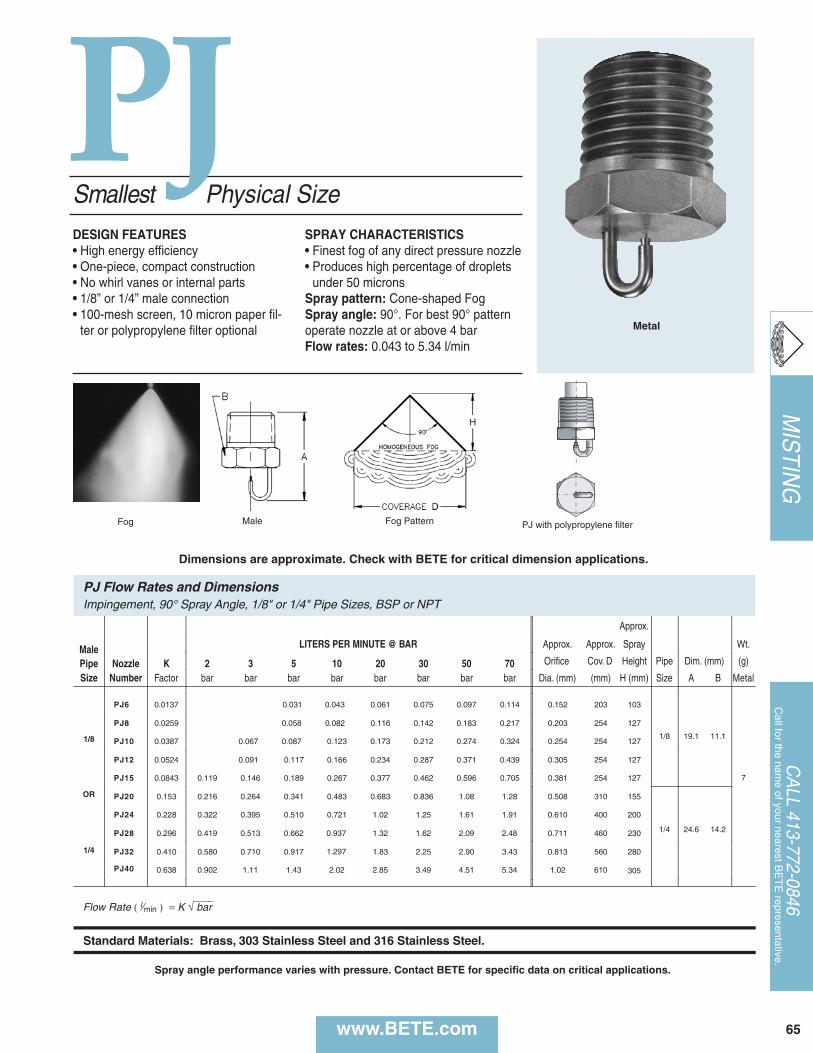
Approx.
Male LITERS PER MINUTE @ BAR Approx. Approx. Spray Wt.
Pipe Nozzle K 2 3 5 10 20 30 50 70 Orifice Cov. D Height Pipe Dim. (mm) (g)
Size Number Factor bar bar bar bar bar bar bar bar Dia. (mm) (mm) H (mm) Size A B Metal
PJ6 0.0137 0.043 0.061 0.075 0.097 0.114 0.152 203 103
1/8 19.1 11.1
7
1/8
PJ8 0.0259 0.058 0.082 0.116 0.142 0.183 0.217 0.203 254 127
PJ10 0.0387 0.067 0.087 0.123 0.173 0.212 0.274 0.324 0.254 254 127
PJ12 0.0524 0.091 0.117 0.166 0.234 0.287 0.371 0.439 0.305 254 127
OR
PJ15 0.0843 0.119 0.146 0.189 0.267 0.377 0.462 0.596 0.705 0.381 254 127
PJ20 0.153 0.216 0.264 0.341 0.483 0.683 0.836 1.08 1.28 0.508 310 155
1/4 24.6 14.2
PJ24 0.228 0.322 0.395 0.510 0.721 1.02 1.25 1.61 1.91 0.610 400 200
1/4
PJ28 0.296 0.419 0.513 0.662 0.937 1.32 1.62 2.09 2.48 0.711 460 230
PJ32 0.410 0.580 0.710 0.917 1.297 1.83 2.25 2.90 3.43 0.813 560 280
PJ40 0.638 0.902 1.11 1.43 2.02 2.85 3.49 4.51 5.34 1.02 610 305
Flow Rate ( l⁄min ) = K √⎯⎯⎯⎯ bar
Standard Materials: Brass, 303 Stainless Steel and 316 Stainless Steel.
0.031
PJ Flow Rates and DimensionsImpingement, 90° Spray Angle, 1/8" or 1/4" Pipe Sizes, BSP or NPT
Smallest Physical SizeDESIGN FEATURES• High energy efficiency• One-piece, compact construction• No whirl vanes or internal parts • 1/8” or 1/4” male connection• 100-mesh screen, 10 micron paper fil-
ter or polypropylene filter optional
SPRAY CHARACTERISTICS• Finest fog of any direct pressure nozzle• Produces high percentage of droplets
under 50 micronsSpray pattern: Cone-shaped FogSpray angle: 90°. For best 90° patternoperate nozzle at or above 4 barFlow rates: 0.043 to 5.34 l/min
Fog Male Fog Pattern
Metal
Dimensions are approximate. Check with BETE for critical dimension applications.
PJ with polypropylene filter
PJ
www.BETE.com
MIS
TING
65
CA
LL 413-772-0846C
all for the name of your nearest B
ET
E representative.
Spray angle performance varies with pressure. Contact BETE for specific data on critical applications.
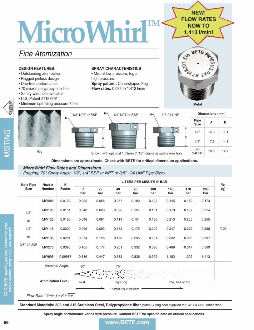
MIS
TIN
G
66
TO O
RD
ER:s
peci
fy p
ipe
size
, con
nect
ion
type
, no
zzle
num
ber,
spra
y an
gle,
and
mat
eria
l.
www.BETE.com
MicroWhirlTM
Flow Rate ( l/min ) = K √ bar
Fine Atomization
DESIGN FEATURES• Outstanding atomization• Rugged pinless design• Drip-free performance• 70 micron polypropylene filter • Safety wire hole available• U.S. Patent #7198201• Minimum operating pressure 7 bar
SPRAY CHARACTERISTICS• Mist at low pressure; fog at high pressureSpray pattern: Cone-shaped FogFlow rates: 0.032 to 1.413 l/min
Fog
Metal
Shown with optional 1.59mm (1/16”) diameter safety wire hole
1/8” NPT or BSP 1/4” NPT or BSP 3/8-24 UNF
Male PipeSize
NozzleNumber
K Factor
LITERS PER MINUTE @ BARWt(g)7
bar20bar
40bar
70bar
100bar
140bar
170bar
200bar
1/8”
or
1/4”
or
3/8”-24UNF
MW085 0.0122 0.032 0.055 0.077 0.102 0.122 0.145 0.160 0.173
7.09
MW105 0.0151 0.040 0.068 0.096 0.127 0.151 0.179 0.197 0.214
MW125 0.0180 0.048 0.081 0.114 0.151 0.180 0.213 0.235 0.255
MW145 0.0209 0.055 0.093 0.132 0.175 0.209 0.247 0.272 0.296
MW195 0.0281 0.074 0.126 0.178 0.235 0.281 0.332 0.366 0.397
MW275 0.0396 0.105 0.177 0.251 0.332 0.396 0.469 0.517 0.560
MW695 0.09988 0.316 0.447 0.632 0.836 0.999 1.182 1.302 1.413
MicroWhirl Flow Rates and DimensionsFogging, 70° Spray Angle, 1/8”, 1/4” BSP or NPT or 3/8” - 24 UNF Pipe Sizes
Standard Materials: 303 and 316 Stainless Steel, Polypropylene filter (Viton O-ring seal supplied for 3/8”-24 UNF connection)
PipeSize
A B
1/8” 12.3 11.1
1/4” 17.5 14.3
3/8-24UNF
10.8 12.7
Dimensions (mm)
Nominal Angle 20° 70°
mist light fog fine, heavy fogAtomization Level
Dimensions are approximate. Check with BETE for critical dimension applications.
Spray angle performance varies with pressure. Contact BETE for specific data on critical applications.
increasing pressure
NEW!FLOW RATES
NOW TO 1.413 l/min!
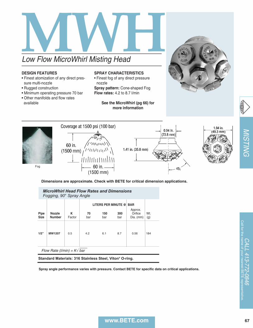
www.BETE.com 67
MIS
TING
CA
LL 413-772-0846C
all for the name of your nearest B
ET
E representative.
Spray angle performance varies with pressure. Contact BETE for specific data on critical applications.
MWHLow Flow MicroWhirl Misting Head
DESIGN FEATURES• Finest atomization of any direct pres-
sure multi-nozzle• Rugged construction• Minimum operating pressure 70 bar • Other manifolds and flow rates available
SPRAY CHARACTERISTICS• Finest fog of any direct pressure
nozzleSpray pattern: Cone-shaped FogFlow rates: 4.2 to 8.7 l/min
See the MicroWhirl (pg 66) for more information
Fog
Coverage Chart
LITERS PER MINUTE @ BAR
Approx.Pipe Nozzle K 70 150 300 Orifice Wt.Size Number Factor bar bar bar Dia. (mm) (g)
1/2” MW1207 0.5 4.2 6.1 8.7 0.56 184
Flow Rate (l/min) = K√ bar
Standard Materials: 316 Stainless Steel, Viton® O-ring.
MicroWhirl Head Flow Rates and DimensionsFogging, 90° Spray Angle
Dimensions are approximate. Check with BETE for critical dimension applications.
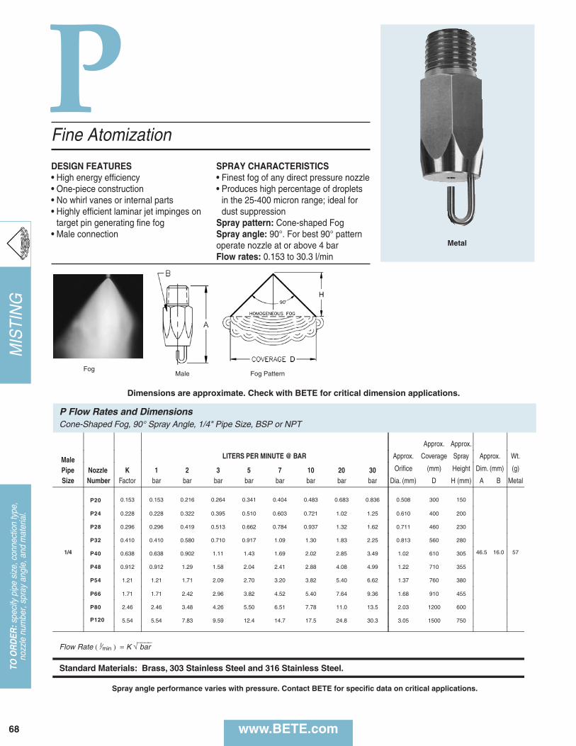
P
P Flow Rates and DimensionsCone-Shaped Fog, 90° Spray Angle, 1/4" Pipe Size, BSP or NPT
Approx. Approx.
Male LITERS PER MINUTE @ BAR Approx. Coverage Spray Approx. Wt.
Pipe Nozzle K 1 2 3 5 7 10 20 30 Orifice (mm) Height Dim. (mm) (g)
Size Number Factor bar bar bar bar bar bar bar bar Dia. (mm) D H (mm) A B Metal
1/4
P20 0.153 0.153 0.216 0.264 0.341 0.404 0.483 0.683 0.836 0.508 300 150
46.5 16.0 57
P24 0.228 0.228 0.322 0.395 0.510 0.603 0.721 1.02 1.25 0.610 400 200
P28 0.296 0.296 0.419 0.513 0.662 0.784 0.937 1.32 1.62 0.711 460 230
P32 0.410 0.410 0.580 0.710 0.917 1.09 1.30 1.83 2.25 0.813 560 280
P40 0.638 0.638 0.902 1.11 1.43 1.69 2.02 2.85 3.49 1.02 610 305
P48 0.912 0.912 1.29 1.58 2.04 2.41 2.88 4.08 4.99 1.22 710 355
P54 1.21 1.21 1.71 2.09 2.70 3.20 3.82 5.40 6.62 1.37 760 380
P66 1.71 1.71 2.42 2.96 3.82 4.52 5.40 7.64 9.36 1.68 910 455
P80 2.46 2.46 3.48 4.26 5.50 6.51 7.78 11.0 13.5 2.03 1200 600
P120 5.54 5.54 7.83 9.59 12.4 14.7 17.5 24.8 30.3 3.05 1500 750
Flow Rate ( l⁄min ) = K √⎯⎯⎯⎯ bar
Standard Materials: Brass, 303 Stainless Steel and 316 Stainless Steel.
www.BETE.com
Fine Atomization
DESIGN FEATURES• High energy efficiency• One-piece construction• No whirl vanes or internal parts• Highly efficient laminar jet impinges on
target pin generating fine fog• Male connection
SPRAY CHARACTERISTICS• Finest fog of any direct pressure nozzle• Produces high percentage of droplets
in the 25-400 micron range; ideal fordust suppression
Spray pattern: Cone-shaped FogSpray angle: 90°. For best 90° patternoperate nozzle at or above 4 barFlow rates: 0.153 to 30.3 l/min
FogMale
Metal
Fog Pattern
Dimensions are approximate. Check with BETE for critical dimension applications.
68
TO O
RD
ER:s
peci
fy p
ipe
size
, con
nect
ion
type
, no
zzle
num
ber,
spra
y an
gle,
and
mat
eria
l.M
ISTI
NG
Spray angle performance varies with pressure. Contact BETE for specific data on critical applications.
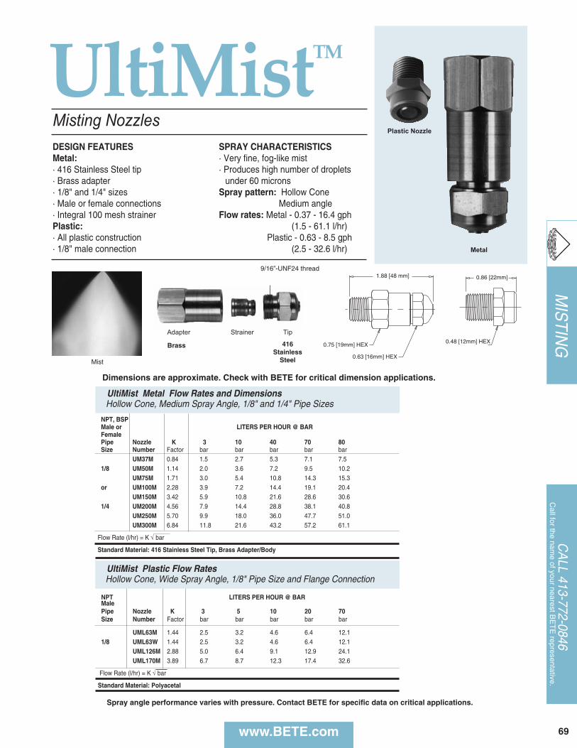
NPT LITERS PER HOUR @ BARMalePipe Nozzle K 3 5 10 20 70 Size Number Factor bar bar bar bar bar
UML63M 1.44 2.5 3.2 4.6 6.4 12.11/8 UML63W 1.44 2.5 3.2 4.6 6.4 12.1
UML126M 2.88 5.0 6.4 9.1 12.9 24.1UML170M 3.89 6.7 8.7 12.3 17.4 32.6
Flow Rate (l/hr) = K √ bar
Standard Material: Polyacetal
UltiMist Plastic Flow RatesHollow Cone, Wide Spray Angle, 1/8" Pipe Size and Flange Connection
www.BETE.com 69
MIS
TING
CA
LL 413-772-0846C
all for the name of your nearest B
ET
E representative.
NPT, BSPMale or LITERS PER HOUR @ BARFemalePipe Nozzle K 3 10 40 70 80Size Number Factor bar bar bar bar bar
UM37M 0.84 1.5 2.7 5.3 7.1 7.51/8 UM50M 1.14 2.0 3.6 7.2 9.5 10.2
UM75M 1.71 3.0 5.4 10.8 14.3 15.3or UM100M 2.28 3.9 7.2 14.4 19.1 20.4
UM150M 3.42 5.9 10.8 21.6 28.6 30.61/4 UM200M 4.56 7.9 14.4 28.8 38.1 40.8
UM250M 5.70 9.9 18.0 36.0 47.7 51.0UM300M 6.84 11.8 21.6 43.2 57.2 61.1
Flow Rate (l/hr) = K √ bar
Standard Material: 416 Stainless Steel Tip, Brass Adapter/Body
Mist
DESIGN FEATURESMetal:· 416 Stainless Steel tip· Brass adapter · 1/8" and 1/4" sizes· Male or female connections· Integral 100 mesh strainerPlastic:· All plastic construction · 1/8" male connection
SPRAY CHARACTERISTICS · Very fine, fog-like mist· Produces high number of droplets
under 60 micronsSpray pattern: Hollow Cone
Medium angleFlow rates: Metal - 0.37 - 16.4 gph
(1.5 - 61.1 l/hr)Plastic - 0.63 - 8.5 gph
(2.5 - 32.6 l/hr)
Misting Nozzles
UltiMist Metal Flow Rates and DimensionsHollow Cone, Medium Spray Angle, 1/8" and 1/4" Pipe Sizes
1.88 [48 mm]
0.75 [19mm] HEX
0.63 [16mm] HEX
Plastic Nozzle
0.86 [22mm]
0.48 [12mm] HEX
Metal
Adapter Strainer Tip
9/16”-UNF24 thread
UltiMistTM
Spray angle performance varies with pressure. Contact BETE for specific data on critical applications.
Dimensions are approximate. Check with BETE for critical dimension applications.
Brass 416Stainless
Steel
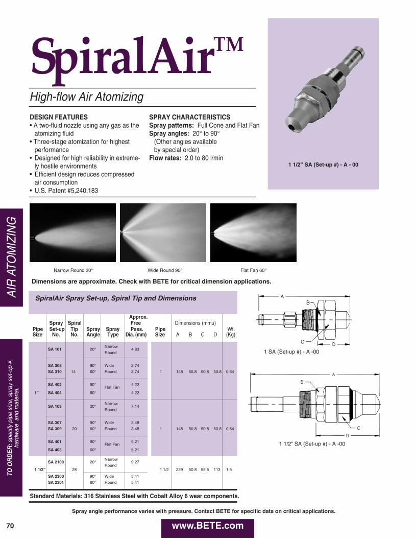
AIR
ATO
MIZ
ING
www.BETE.com70
1 1/2” SA (Set-up #) - A - 00
TO O
RD
ER:s
peci
fy p
ipe
size
, spr
ay s
et-u
p #,
ha
rdw
are
and
mat
eria
l.
High-flow Air Atomizing
DESIGN FEATURES• A two-fluid nozzle using any gas as the
atomizing fluid• Three-stage atomization for highest
performance• Designed for high reliability in extreme-
ly hostile environments• Efficient design reduces compressed
air consumption• U.S. Patent #5,240,183
SPRAY CHARACTERISTICSSpray patterns: Full Cone and Flat FanSpray angles: 20° to 90°
(Other angles available by special order)
Flow rates: 2.0 to 80 l/min
Approx.Spray Spiral Free Dimensions (mmu)
Pipe Set-up Tip Spray Spray Pass. Pipe Wt.Size No. No. Angle Type Dia. (mm) Size A B C D (Kg)
SA 101 20°Narrow
4.83Round
SA 308 90° Wide 2.74
SA 310 14 60° Round 2.74 1 148 50.8 50.8 50.8 0.64
SA 402 90°Flat Fan
4.22
1” SA 404 60° 4.22
SA 103 20°Narrow
7.14Round
SA 307 90° Wide 3.48
SA 309 20 60° Round 3.48 1 148 50.8 50.8 50.8 0.64
SA 401 90°Flat Fan
5.21
SA 403 60° 5.21
SA 2100 20°Narrow
9.27
1 1/2” 28Round
1 1/2 229 50.8 55.6 113 1.5
SA 2300 90° Wide 5.41
SA 2301 60° Round 5.41
Standard Materials: 316 Stainless Steel with Cobalt Alloy 6 wear components.
SpiralAir Spray Set-up, Spiral Tip and Dimensions
1 1/2” SA (Set-up #) - A -00
1 SA (Set-up #) - A -00
Narrow Round 20° Wide Round 90° Flat Fan 60°
Dimensions are approximate. Check with BETE for critical dimension applications.
SpiralAirTM
Spray angle performance varies with pressure. Contact BETE for specific data on critical applications.
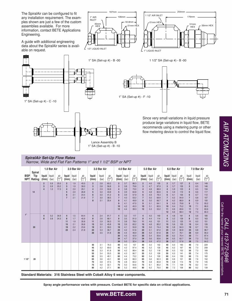
71
AIR
ATOM
IZING
CA
LL 413-772-0846C
all for the name of your nearest B
ET
E representative.
SpiralAir Set-Up Flow RatesNarrow, Wide and Flat Fan Patterns 1" and 1 1/2" BSP or NPT
1.0 Bar Air 2.0 Bar Air 3.0 Bar Air 4.0 Bar Air 5.0 Bar Air 6.0 Bar AirSpiral
BSP Tip liquid liquid air liquid liquid air liquid liquid air liquid liquid air liquid liquid air liquid liquid airNPT Rating (l/min) (bar) (N
hm3) (l/min) (bar) (N
hm3) (l/min) (bar) (N
hm3) (l/min) (bar) (N
hm3) (l/min) (bar) (N
hm3) (l/min) (bar) (N
hm3)
2 0.9 25.0 2 1.9 45.0 2 2.8 60.2 2 3.7 86.3 2 4.6 105 2 5.7 1373 0.9 20.2 3 1.9 39.0 3 2.8 56.8 3 3.8 79.8 3 4.7 97.9 3 5.7 1354 1.0 17.3 4 2.0 29.1 4 2.9 50.8 4 3.8 73.0 4 4.8 88.9 4 5.9 123
14 5 2.0 26.8 5 3.0 43.8 5 3.9 64.8 5 4.8 82.6 5 5.9 1106 2.1 24.4 6 3.0 41.2 6 3.9 57.9 6 4.9 78.3 6 6.1 1007 2.1 21.9 7 3.0 38.5 7 4.0 53.2 7 5.0 69.9 7 6.2 94.9
8 3.1 35.4 8 4.1 49.9 8 5.0 66.7 8 6.2 88.99 4.1 47.0 9 5.1 64.1 9 6.3 79.810 4.2 45.3 10 5.1 60.5 10 6.4 75.212 4.4 39.3 12 5.3 53.2 11 6.6 69.6
12 6.6 68.41” 4 0.2 34.9 4 1.5 64.4 4 2.4 91.7 4 3.2 117 4 4.0 140 4 4.8 161
8 0.8 24.3 8 1.7 45.9 8 2.6 68.1 8 3.5 91.0 8 4.4 114 8 5.2 13911 1.9 35.8 11 2.9 56.3 11 3.8 78.0 11 4.6 101 11 5.3 12515 2.1 26.8 15 3.0 45.8 15 3.9 65.2 15 4.8 85.2 15 5.6 105
20 19 2.2 23.6 19 3.1 39.0 19 4.1 55.9 19 5.0 74.4 19 5.8 94.323 2.4 21.8 23 3.3 36.7 23 4.2 51.6 23 5.1 67.2 23 5.9 82.8
26 3.5 31.8 26 4.4 46.9 26 5.2 61.6 26 6.1 76.130 4.5 42.9 30 5.4 55.6 30 6.2 70.434 4.7 37.0 34 5.6 50.6 34 6.5 62.738 5.0 32.4 38 5.9 47.2 38 6.7 57.8
40 3.1 76.3 40 4.0 107 40 5.0 142 40 6.0 18345 3.2 69.0 45 4.2 97.4 45 5.2 130 45 6.2 16750 3.3 61.8 50 4.2 88.4 50 5.2 118 50 6.3 15255 3.4 55.5 55 4.3 80.7 55 5.3 109 55 6.3 14160 3.5 49.1 60 4.4 73.2 60 5.4 100 60 6.4 130
1 1/2" 28 65 3.6 43.1 65 4.6 66.3 65 5.6 92.3 65 6.6 12170 3.8 37.5 70 4.8 60.2 70 5.8 85.8 70 6.8 11475 4.0 32.1 75 5.0 54.6 75 6.1 80.2 75 7.1 10980 4.2 27.1 80 5.2 49.8 80 6.2 76.0 80 7.2 106
7.0 Bar Air
liquid liquid air (l/min) (bar) (N
hm3)
2 6.4 1493 6.5 1464 6.5 1345 6.6 1176 6.7 1127 6.8 1078 6.9 1009 7.0 93.210 7.1 86.011 7.2 83.612 7.3 80.3
4 5.6 1808 6.0 16311 6.0 15115 6.4 12619 6.7 11623 6.8 98.726 6.9 90.230 7.1 87.434 7.3 73.238 7.5 64.2
40 7.0 22945 7.3 20850 7.3 18955 7.4 17560 7.5 16265 7.6 15270 7.9 14575 8.2 14180 8.2 139
Standard Materials: 316 Stainless Steel with Cobalt Alloy 6 wear components.
254mm
176mm
113mm
2" HEX 2 13/16" HEX2" HEX
1 1/2" AIR INLET
1" LIQUID INLET1/2" LIQUID INLET
1" AIR INLET
2" HEX1 3/8" HEX
170mm
106mm
51.6mm
The SpiralAir can be configured to fitany installation requirement. The exam-ples shown are just a few of the customassemblies available. For more information, contact BETE ApplicationsEngineering.
A guide with additional engineeringdata about the SpiralAir series is avail-able on request.
Since very small variations in liquid pressureproduce large variations in liquid flow, BETErecommends using a metering pump or otherflow metering device to control the liquid flow.
1” SA (Set-up #) - C -10
1” SA (Set-up #) - B -00 1 1/2” SA (Set-up #) - B -00
1” SA (Set-up #) - F -10
1” LIQUID INLET1/2” LIQUID INLET
1” AIR INLET
1 1/2” AIR INLET
51mm HEX51mm HEX 56mm HEX
167mm
106mm
50.8mm
254mm
176mm
Lance Assembly B1” SA (Set-up #) - B -10
www.BETE.com
Spray angle performance varies with pressure. Contact BETE for specific data on critical applications.
51mmHEX
35mmHEX
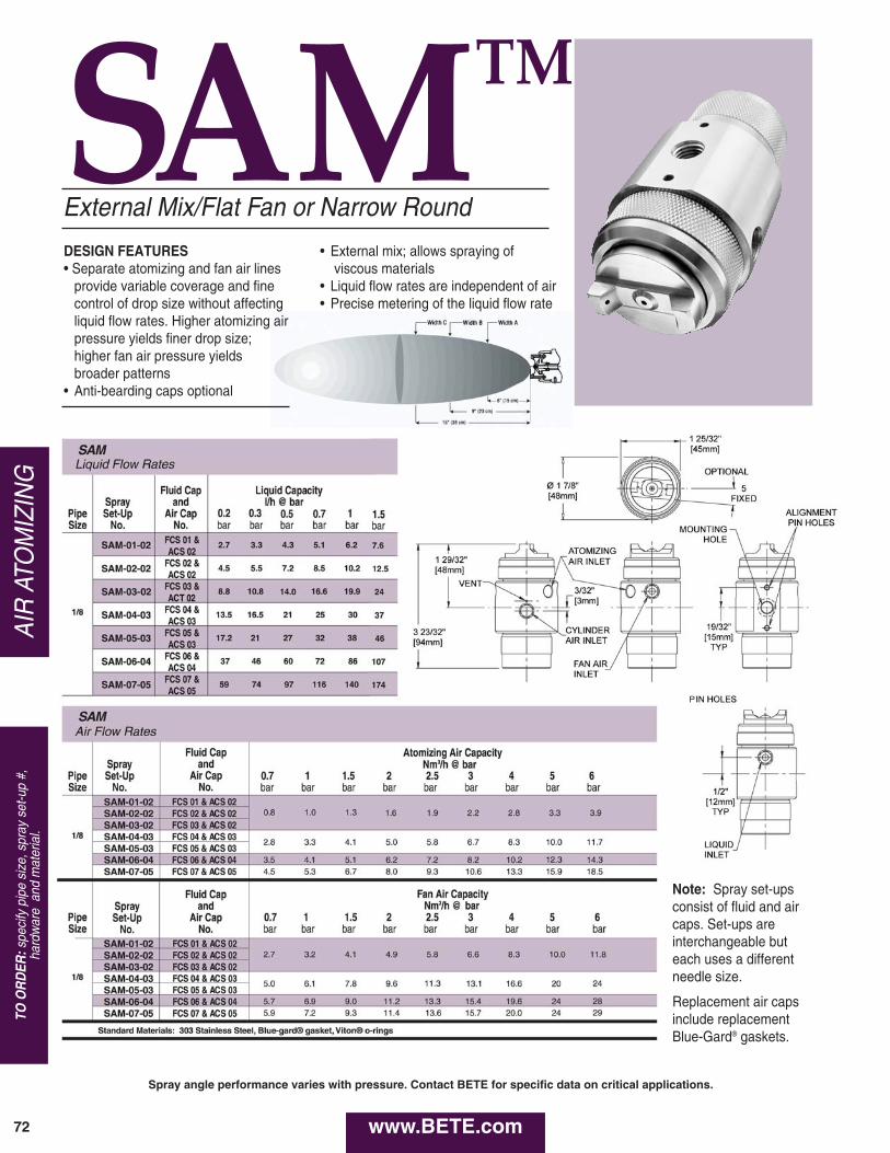
SAMTMA
IR A
TOM
IZIN
G
72
TO O
RD
ER:s
peci
fy p
ipe
size
, spr
ay s
et-u
p #,
ha
rdw
are
and
mat
eria
l.
External Mix/Flat Fan or Narrow Round
P
DESIGN FEATURES• Separate atomizing and fan air lines
provide variable coverage and finecontrol of drop size without affectingliquid flow rates. Higher atomizing airpressure yields finer drop size; higher fan air pressure yields broader patterns
• Anti-bearding caps optional
• External mix; allows spraying ofviscous materials
• Liquid flow rates are independent of air• Precise metering of the liquid flow rate
Note: Spray set-upsconsist of fluid and aircaps. Set-ups are interchangeable buteach uses a differentneedle size.
Replacement air capsinclude replacementBlue-Gard® gaskets.
www.BETE.com
Spray angle performance varies with pressure. Contact BETE for specific data on critical applications.
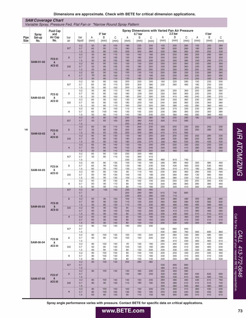
73
AIR
ATOM
IZING
CA
LL 413-772-0846C
all for the name of your nearest B
ET
E representative.
SAM Coverage ChartVariable Spray, Pressure Fed, Flat Fan or *Narrow Round Spray Pattern
0.70.2 50 80 100 180 230 250 150 200 280 150 200 2800.7 60 90 110 180 250 300 180 200 280 180 200 3001.5 50 80 100 200 300 360 230 280 360 200 250 330
20.2 50 80 110 130 150 180 200 250 360 200 280 3600.7 50 60 .130 150 180 250 200 250 330 200 250 3001.5 50 80 100 180 230 330 250 300 380 240 290 370
2.50.2 60 90 150 130 150 200 200 250 360 230 280 3600.7 50 80 130 150 180 250 230 280 360 230 280 3301.5 50 80 110 180 200 300 250 300 360 250 300 380
40.2 60 90 150 100 130 150 200 280 330 230 280 3600.7 50 80 130 110 130 180 200 250 360 230 300 3801.5 50 80 110 130 180 230 230 300 410 250 330 430
0.70.2 50 80 100 200 250 300 160 220 280 150 230 3000.7 60 90 110 200 300 380 230 360 460 180 250 3301.5 50 80 100 200 300 380 200 250 330
20.2 50 80 110 140 180 200 200 250 360 200 280 360
1/8
0.7 50 80 130 180 230 300 250 300 360 230 250 3301.5 50 80 100 180 250 300 330 410 460 240 290 370
2.50.2 60 90 150 130 180 230 200 250 360 230 280 3600.7 50 80 130 180 200 160 240 300 360 230 300 3801.5 50 80 110 160 230 320 290 380 430 280 360 460
40.2 60 90 150 110 140 180 200 270 330 230 280 3600.7 60 100 140 130 150 220 230 280 360 250 300 3801.5 50 80 110 140 190 240 250 360 460 280 360 460
0.70.2 50 80 130 230 300 380 180 230 280 180 230 3000.7 50 60 100 300 380 530 300 510 5801.5 250 300 410
20.2 60 80 110 150 200 230 200 250 330 200 250 3300.7 50 80 130 200 280 380 280 330 330 250 280 3301.5 50 60 100 200 300 360 410 510 560
2.50.2 60 90 130 130 180 250 200 250 330 200 280 3300.7 50 80 130 180 200 280 280 330 380 250 300 3301.5 50 80 130 180 230 370 330 460 530 300 430 530
40.2 60 90 140 130 150 200 200 250 330 200 250 3300.7 60 90 140 150 180 240 250 330 410 280 330 3801.5 50 80 110 150 200 250 300 460 560 330 460 530
0.70.2 60 90 130 230 330 4800.7 50 80 110 150 360 4101.5 230 330 480 460 610 740
20.2 60 80 130 100 130 180 280 380 460 300 380 4600.7 60 90 130 130 180 230 330 430 560 200 530 6601.5 60 90 140 130 150 230 330 510 610 180 560 690
2.50.2 60 80 130 90 110 160 230 300 360 280 330 4600.7 60 90 130 100 130 180 250 360 460 130 460 5601.5 60 90 130 100 140 200 280 380 530 150 510 630
40.2 60 90 130 80 100 150 200 250 330 250 300 4300.7 60 90 110 80 100 150 200 280 360 280 380 4601.5 60 90 110 80 110 180 250 300 410 300 430 560
0.7 0.2 80 100 150 230 300 4600.7 200 280 380 610 740 8901.5 230 300 380 530 710
2 0.2 60 90 150 100 150 200 300 380 480 300 380 4800.7 60 90 130 110 150 200 360 460 580 430 560 6301.5 50 80 130 110 150 230 380 480 690 460 580 690
2.5 0.2 60 90 150 90 130 180 250 330 430 300 360 4600.7 60 90 140 100 150 200 300 410 510 380 460 5601.5 60 90 140 90 130 230 330 430 560 410 510 610
4 0.2 60 90 150 60 100 180 230 280 360 250 300 4300.7 60 90 140 80 100 150 250 330 410 330 410 5101.5 60 90 140 80 100 150 230 330 430 300 430 580
0.70.2 80 100 130 180 250 3300.7 530 660 8401.5 430 560 760 560 690 860
20.2 80 100 130 100 150 200 300 360 530 380 480 5600.7 60 90 130 100 150 220 330 410 560 410 530 5801.5 280 410 530 460 460 610
2.50.2 80 100 140 40 130 180 250 300 430 300 430 5300.7 60 90 130 100 130 180 280 360 510 360 460 6401.5 60 90 130 80 130 200 230 330 430 330 460 660
40.2 80 100 150 80 100 150 200 250 330 250 330 4600.7 80 100 130 90 110 180 230 300 410 300 410 5301.5 80 90 130 80 100 140 200 250 380 300 410 530
0.70.2 80 100 130 200 280 3800.7 530 690 8901.5 480 610 840
20.2 80 100 130 130 160 230 330 460 5800.7 150 180 250 330 430 560 430 630 6901.5 360 430 610 460 560 740
2.50.2 80 100 140 140 150 230 280 380 480 430 610 7600.7 80 90 130 110 180 190 300 380 510 410 510 7401.5 300 360 530 360 480 690
40.2 80 100 150 100 150 200 230 300 410 360 430 5300.7 80 100 160 130 160 190 250 330 430 330 430 5801.5 60 80 130 90 110 150 180 360 380 310 410 610
PipeSize
SpraySet-up
No.
Fluid Capand
Air CapNo.
barair
barliquid
A(mm)
C(mm)
B(mm)
0* barA
(mm)C
(mm)B
(mm)
0.7 barA
(mm)C
(mm)B
(mm)
2.5 barA
(mm)C
(mm)B
(mm)
4 barSpray Dimensions with Varied Fan Air Pressure
FCS 01&
ACS 02
FCS 02&
ACS 02
FCS 03&
ACS 02
FCS 04&
ACS 03
FCS 05&
ACS 03
FCS 06&
ACS 04
FCS 07&
ACS 05
SAM-01-02
SAM-02-02
SAM-03-02
SAM-04-03
SAM-05-03
SAM-06-04
SAM-07-05
Dimensions are approximate. Check with BETE for critical dimension applications.
www.BETE.com
Spray angle performance varies with pressure. Contact BETE for specific data on critical applications.
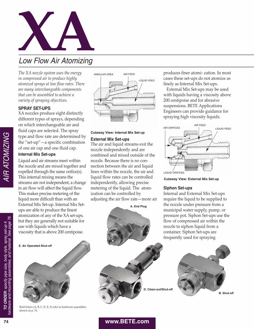
External Mix Set-upsThe air and liquid streams exit thenozzle independently and arecombined and mixed outside of thenozzle. Because there is no con‑nection between the air and liquidlines within the nozzle, the air andliquid flow rates can be controlledindependently, allowing precisemetering of the liquid. The atom‑ization can be controlled byadjusting the air flow rate—more air
XA
www.BETE.com
Low Flow Air Atomizing
74
The XA nozzle system uses the energy in compressed air to produce highlyatomized sprays at low flow rates. Thereare many interchangeable componentsthat can be assembled to achieve avariety of spraying objectives.
SPRAY SET-UPSXA nozzles produce eight distinctlydifferent types of sprays, dependingon which interchangeable air andfluid caps are selected. The spraytype and flow rate are determined bythe ”set‑up”—a specific combinationof one air cap and one fluid cap.Internal Mix Set-upsLiquid and air streams meet withinthe nozzle and are mixed together andexpelled through the same orifice(s).This internal mixing means thestreams are not independent; a changein air flow will affect the liquid flow.This makes precise metering of theliquid more difficult than with anExternal Mix Set‑up. Internal Mix Set‑ups are able to produce the finestatomization of any of the XA set‑ups,but they are generally not suitable foruse with liquids which have aviscosity that is above 200 centipoise.
produces finer atomi‑ zation. In mostcases these set‑ups do not atomize asfinely as Internal Mix Set‑ups.
External Mix Set‑ups may be usedwith liquids having a viscosity above200 centipoise and for abrasivesuspensions. BETE ApplicationsEngineers can provide guidance forspraying high viscosity liquids.
Siphon Set-upsInternal and External Mix Set‑upsrequire the liquid to be supplied tothe nozzle under pressure from amunicipal water supply, pump, orpressure pot. Siphon Set‑ups use theflow of compressed air within thenozzle to siphon liquid from acontainer. Siphon Set‑ups arefrequently used for spraying
Cutaway View: Internal Mix Set-up
Cutaway View: External Mix Set-upAIR
ATO
MIZ
ING
E. Air Operated Shut-off
A. End Plug
Bold letters (A, B, C, D, E, F) refer to hardware assembliesshown on p. 76.
D. Clean-out/Shut-offB. Shut-off
TO O
RD
ER:s
peci
fy p
ipe
size
, bod
y st
yle,
spr
ay s
et-u
p #,
hard
war
e an
d m
ount
ing
asse
mbl
ies,
and
mat
eria
l. S
ee p
age
76.
ANNULAR AREA AIR FEED
LIQUID FEED
AIR FEEDLIQUID FEEDAIR ORIFICES
LIQUID ORIFICES
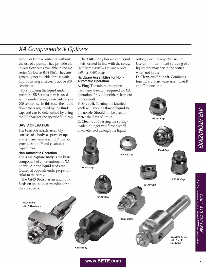
XW Air Cap
XA 01/02 Bodywith E or FHardware
CA
LL 413-772-0846C
all for the name of your nearest B
ET
E representative.
75
The XA05 Body has air and liquidinlets located in‑line with the spray.Hardware assemblies cannot be usedwith the XA05 body.
A. Plug. The minimum optionhardware assembly required for XAoperation. Provides neither clean‑outnor shut‑off.B. Shut‑off. Turning the knurledknob will stop the flow of liquid tothe nozzle. Should not be used tometer the flow of liquid.C. Clean‑out. Pressing the spring‑loaded plunger will force a smalldia‑meter rod through the liquid
orifice, cleaning any obstruction.Useful for intermittent spraying of aliquid that may dry in the orificewhen not in use.D. Clean‑out/Shut‑off. Combinesfunctions of hardware assemblies Band C in one unit.
additives from a container withoutthe use of a pump. They provide thelowest flow rates available in the XAseries (as low as 0.38 l/hr). They aregenerally not suitable for use withliquids having a viscosity above 200centipoise.
By supplying the liquid underpressure, SR Set‑ups may be usedwith liquids having a viscosity above200 centipoise. In this case, the liquidflow rate is regulated by the fluidcap, and can be determined by usingthe EF chart for the specific fluid cap.
The basic XA nozzle assemblyconsists of a body, a spray set‑up,and a “hardware assembly” that canprovide shut‑off and clean‑outcapabilities.
The XA00 Square Body is the basiccomponent of a non‑automatic XAnozzle. Air and liquid feeds arelocated at opposite ends, perpendi‑cular to the spray.
The XA03 Body has air and liquidfeeds on one side, perpendicular tothe spray axis.
PF Air Cap
AIR
ATOM
IZING
XA05 Body
XA03 Body
XA00 Body
with C Hardware
Fluid Cap
FF Air Cap
SR Air Cap
PR Air Cap
BASIC OPERATION
Non-Automatic Operation
Hardware Assemblies for Non-Automatic Operation
XA Components & Options
EF Air Cap
www.BETE.com
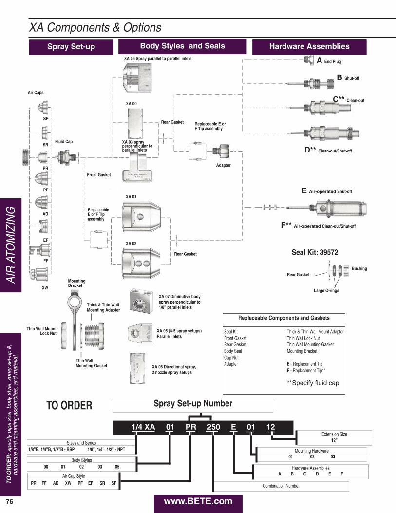
SF
SR
PR
PF
AD
EF
FF
XW
Fluid Cap
Front Gasket
Air Caps
XA 00
Rear Gasket
Rear Gasket
Replaceable E orF Tip assembly
A End Plug
B Shut-off
C** Clean-out
D** Clean-out/Shut-off
E Air-operated Shut-off
F** Air-operated Clean-out/Shut-off
Adapter
ReplaceableE or F Tipassembly
Rear Gasket Seal Kit: 39572
Bushing
Large O-rings
MountingBracket
Thin Wall MountLock Nut
Thick & Thin WallMounting Adapter
Thin WallMounting Gasket
Replaceable Components and Gaskets
Seal KitFront GasketRear GasketBody SealCap NutAdapter
Thick & Thin Wall Mount AdapterThin Wall Lock NutThin Wall Mounting GasketMounting Bracket
E - Replacement TipF - Replacement Tip**
**Specify fluid cap
XA 08 Directional spray,2 nozzle spray setups
XA 06 (4-5 spray setups)Parallel inlets
XA 05 Spray parallel to parallel inlets
XA 03 spray perpendicular to parallel inlets
XA 07 Diminutive bodyspray perpendicular to1/8” parallel inlets
XA 01
XA 02
76
TO O
RD
ER:s
peci
fy p
ipe
size
, bod
y st
yle,
spr
ay s
et-u
p #,
hard
war
e an
d m
ount
ing
asse
mbl
ies,
and
mat
eria
l. A
IR A
TOM
IZIN
GXA Components & Options
Spray Set-up Body Styles and Seals Hardware Assemblies
Spray Set-up Number
Sizes and Series1/8”B, 1/4”B, 1/2”B - BSP 1/8”, 1/4”, 1/2” - NPT
Body Styles00 01 02 03 05
Air Cap StylePR FF AD XW PF EF SR SF
Mounting Hardware01 02 03
Extension Size12”
Hardware AssembliesA B C D E F
Combination Number
1/4 XA 01 PR 250 E 01 12
TO ORDER
www.BETE.com
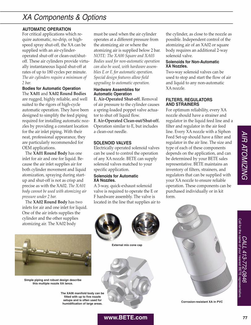
AIR
ATOM
IZING
CA
LL 413-772-0846C
all for the name of your nearest B
ET
E representative.
77
For critical applications which re‑quire automatic, no‑drip, or high‑speed spray shut‑off, the XA can besupplied with an air‑cylinder‑operated shut‑off or clean‑out/shut‑off. These air cylinders provide virtu‑ally instantaneous liquid shut‑off atrates of up to 180 cycles per minute.The air cylinders require a minimum of 2 bar.
The XA01 and XA02 Round Bodiesare rugged, highly reliable, and wellsuited to the rigors of high‑cycleautomatic operation. They have beendesigned to simplify the feed pipingrequired for installing automatic noz‑zles by providing a constant locationfor the air inlet piping. With theirneat, professional appearance, theyare particularly recommended forOEM applications.
The XA01 Round Body has oneinlet for air and one for liquid. Be‑cause the air inlet supplies air forboth cylinder movement and liquidatomization, spraying during start‑up and shut‑off is not as crisp andprecise as with the XA02. The XA01body cannot be used with atomizing airpressure under 2 bar.
The XA02 Round Body has twoinlets for air and one inlet for liquid.One of the air inlets supplies thecylinder and the other suppliesatomizing air. The XA02 body
must be used when the air cylinderoperates at a different pressure fromthe atomizing air or where theatomizing air is supplied below 2 bar.NOTE: The XA00 Square and XA03Bodies used for non‑automatic operationcan also be used, with hardware assem‑blies E or F, for automatic operation.Special design features allow fieldupgrading to automatic operation.
E. Air‑Operated Shut‑off. Removalof air pressure to the cylinder causesa spring‑loaded poppet valve actua‑tor to shut off liquid flow.F. Air‑Operated Clean‑out/Shut‑off.Operation similar to E, but includesa clean‑out needle.
Electrically operated solenoid valvescan be used to control the operationof any XA nozzle. BETE can supplysolenoid valves matched to yourspecific application.
A 3‑way, quick‑exhaust solenoidvalve is required to operate the E orF hardware assembly. The valve islocated in the line that supplies air to
the cylinder, as close to the nozzle aspossible. Independent control of theatomizing air of an XA02 or squarebody requires an additional 2‑waysolenoid valve.
Two‑way solenoid valves can beused to stop and start the flow of airand liquid to any non‑automatic XA nozzle.
For optimum reliability, every XAnozzle should have a strainer andregulator in the liquid feed line and afilter and regulator in the air feedline. Every XA nozzle with a SiphonFeed Set‑up should have a filter andregulator in the air line. The size andtype of each of these componentsdepends on the application, and canbe determined by your BETE salesrepresentative. BETE maintains aninventory of filters, strainers, andregulators that can be supplied withyour XA nozzle to ensure reliableoperation. These components can bepurchased individually or in kitform.
XA Components & Options
Simple piping and robust design describe this multiple nozzle XA lance.
Corrosion-resistant XA in PVC
AUTOMATIC OPERATION
Bodies for Automatic Operation Hardware Assemblies for Automatic Operation
SOLENOID VALVES
Solenoids for Automatic XA Nozzles.
Solenoids for Non-Automatic XA Nozzles.
FILTERS, REGULATORS AND STRAINERS
www.BETE.com
External mix cone cap
The XA06 manifold body can befitted with up to five nozzle
setups and is often used forhumidification of large areas.
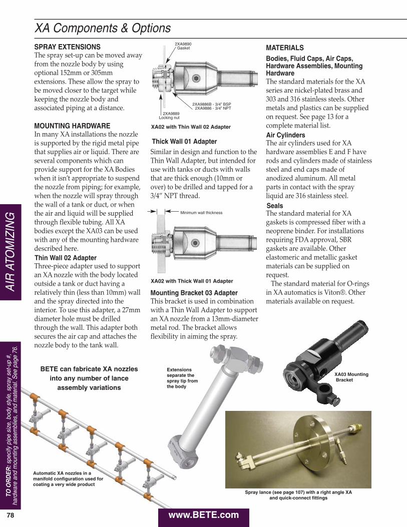
78
The spray set‑up can be moved awayfrom the nozzle body by usingoptional 152mm or 305mmextensions. These allow the spray tobe moved closer to the target whilekeeping the nozzle body andassociated piping at a distance.
In many XA installations the nozzleis supported by the rigid metal pipethat supplies air or liquid. There areseveral components which canprovide support for the XA Bodieswhen it isn’t appropriate to suspendthe nozzle from piping; for example,when the nozzle will spray throughthe wall of a tank or duct, or whenthe air and liquid will be suppliedthrough flexible tubing. All XAbodies except the XA03 can be usedwith any of the mounting hardwaredescribed here.
Three‑piece adapter used to supportan XA nozzle with the body locatedoutside a tank or duct having arelatively thin (less than 10mm) walland the spray directed into theinterior. To use this adapter, a 27mmdiameter hole must be drilledthrough the wall. This adapter bothsecures the air cap and attaches thenozzle body to the tank wall.
Similar in design and function to theThin Wall Adapter, but intended foruse with tanks or ducts with wallsthat are thick enough (10mm orover) to be drilled and tapped for a3/4” NPT thread.
This bracket is used in combinationwith a Thin Wall Adapter to supportan XA nozzle from a 13mm‑diametermetal rod. The bracket allowsflexibility in aiming the spray.
The standard materials for the XAseries are nickel‑plated brass and303 and 316 stainless steels. Othermetals and plastics can be suppliedon request. See page 13 for acomplete material list.
The air cylinders used for XAhardware assemblies E and F haverods and cylinders made of stainlesssteel and end caps made ofanodized aluminum. All metalparts in contact with the sprayliquid are 316 stainless steel.
The standard material for XAgaskets is compressed fiber with aneoprene binder. For installationsrequiring FDA approval, SBRgaskets are available. Otherelastomeric and metallic gasketmaterials can be supplied onrequest.
The standard material for O‑ringsin XA automatics is Viton®. Othermaterials available on request.
TO O
RD
ER:s
peci
fy p
ipe
size
, bod
y st
yle,
spr
ay s
et-u
p #,
hard
war
e an
d m
ount
ing
asse
mbl
ies,
and
mat
eria
l. S
ee p
age
76.
AIR
ATO
MIZ
ING
XA Components & Options
XA02 with Thin Wall 02 Adapter
XA02 with Thick Wall 01 Adapter
XA03 MountingBracket
SPRAY EXTENSIONS
MOUNTING HARDWARE
Thin Wall 02 Adapter
Thick Wall 01 Adapter
Mounting Bracket 03 Adapter
MATERIALSBodies, Fluid Caps, Air Caps,Hardware Assemblies, MountingHardware
Air Cylinders
Seals
2XA9890Gasket
2XA9886B - 3/4” BSP2XA9886 - 3/4” NPT
2XA9889Locking nut
Minimum wall thickness
www.BETE.com
BETE can fabricate XA nozzlesinto any number of lance
assembly variations
Automatic XA nozzles in amanifold configuration used forcoating a very wide product
Extensionsseparate the spray tip from the body
Spray lance (see page 107) with a right angle XA and quick-connect fittings
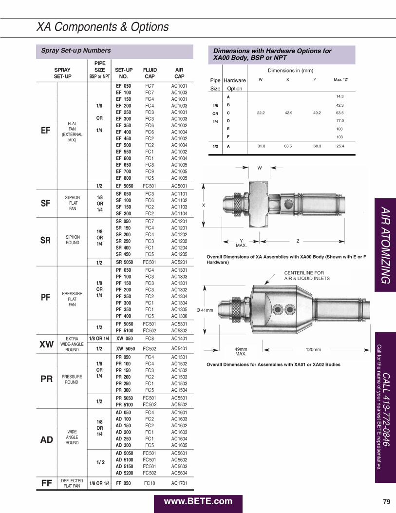
Spray Set-up Numbers
PIPESPRAY SIZE SET-UP FLUID AIRSET-UP BSP or NPT NO. CAP CAP
EF
EF 050 FC7 AC1001EF 100 FC7 AC1003EF 150 FC4 AC1001
1/8
OR
1/4
EF 200 FC4 AC1003EF 250 FC3 AC1001EF 300 FC3 AC1003
FLATFAN
(EXTERNALMIX)
EF 350 FC6 AC1002EF 400 FC6 AC1004EF 450 FC2 AC1002EF 500 FC2 AC1004EF 550 FC1 AC1002EF 600 FC1 AC1004EF 650 FC8 AC1005EF 700 FC9 AC1005EF 800 FC5 AC1005
1/2 EF 5050 FC501 AC5001
SFSIPHON
FLATFAN
1/8OR1/4
SF 050 FC3 AC1101SF 100 FC6 AC1102SF 150 FC2 AC1103SF 200 FC2 AC1104
SR
SR 050 FC7 AC1201
1/8OR1/4
SR 150 FC4 AC1201
SIPHONROUND
SR 200 FC4 AC1202SR 250 FC3 AC1202SR 400 FC1 AC1204SR 450 FC5 AC1205
1/2 SR 5050 FC501 AC5201
PF
PF 050 FC4 AC1301PF 100 FC3 AC1303
1/8OR1/4
PF 150 FC3 AC1301
PRESSUREFLATFAN
PF 200 FC3 AC1302PF 250 FC2 AC1304PF 300 FC1 AC1304PF 350 FC1 AC1305PF 400 FC5 AC1306
1/2PF 5050 FC501 AC5301PF 5100 FC502 AC5302
XWEXTRA
WIDE-ANGLEROUND
1/8 OR 1/4 XW 050 FC8 AC1401
1/2 XW 5050 FC502 AC5401
PR
PR 050 FC4 AC15011/8OR1/4
PR 100 FC4 AC1502PR 150 FC3 AC1502
PRESSURE ROUND
PR 200 FC2 AC1503PR 250 FC1 AC1503PR 300 FC5 AC1504
1/2PR 5050 FC501 AC5501PR 5100 FC502 AC5502
AD
AD 050 FC4 AC1601AD 100 FC2 AC1603AD 150 FC2 AC1602
WIDEANGLEROUND
AD 200 FC1 AC1603AD 250 FC1 AC1604AD 300 FC5 AC1605
1/ 2
AD 5050 FC501 AC5601AD 5100 FC501 AC5602AD 5150 FC501 AC5603AD 5200 FC502 AC5604
FF DEFLECTEDFLAT FAN 1/8 OR 1/4 FF 050 FC10 AC1701
1/8OR1/4
CA
LL 413-772-0846C
all for the name of your nearest B
ET
E representative.
AIR
ATOM
IZING
XA Components & Options
Overall Dimensions of XA Assemblies with XA00 Body (Shown with E or FHardware)
Overall Dimensions for Assemblies with XA01 or XA02 Bodies
Dimensions with Hardware Options for XA00 Body, BSP or NPT
Pipe
Size
Hardware
Option
W X Y Max. "Z"
A
1/8 B
OR C
1/4 D
E
F
1/2 A
Dimensions in (mm)
22.2 42.9 49.2
31.8 63.5 68.3 25.4
14.3
42.3
63.5
77.0
103
103
79
X
W
ZYMAX.
Ø 41mm
120mm49mmMAX.
CENTERLINE FORAIR & LIQUID INLETS
www.BETE.com
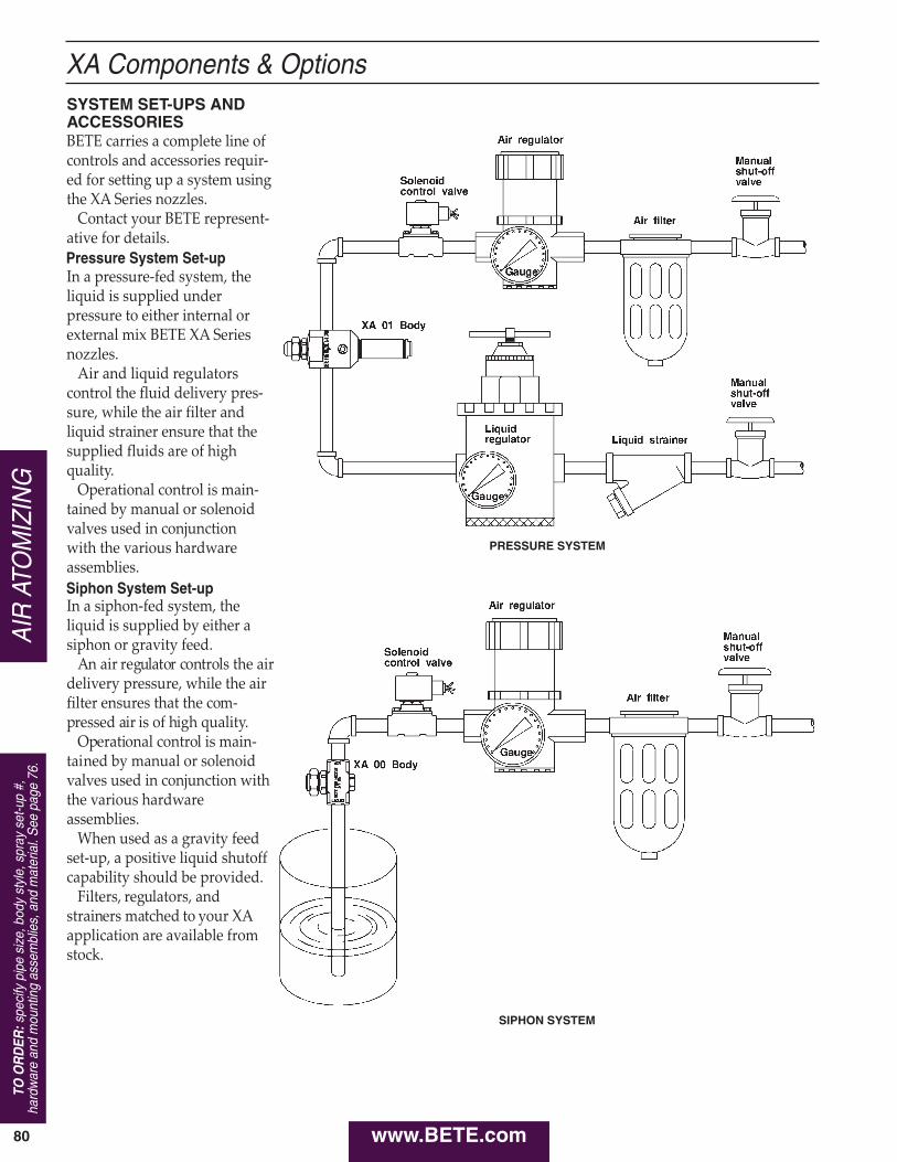
80
TO O
RD
ER:s
peci
fy p
ipe
size
, bod
y st
yle,
spr
ay s
et-u
p #,
hard
war
e an
d m
ount
ing
asse
mbl
ies,
and
mat
eria
l. S
ee p
age
76.
AIR
ATO
MIZ
ING
XA Components & Options
BETE carries a complete line ofcontrols and accessories requir‑ed for setting up a system usingthe XA Series nozzles.
Contact your BETE represent‑ative for details.
In a pressure‑fed system, theliquid is supplied underpressure to either internal orexternal mix BETE XA Seriesnozzles.
Air and liquid regulatorscontrol the fluid delivery pres‑sure, while the air filter andliquid strainer ensure that thesupplied fluids are of highquality.
Operational control is main‑tained by manual or solenoidvalves used in conjunction with the various hardwareassemblies.
In a siphon‑fed system, theliquid is supplied by either asiphon or gravity feed.
An air regulator controls the airdelivery pressure, while the airfilter ensures that the com‑pressed air is of high quality.
Operational control is main‑tained by manual or solenoidvalves used in conjunction withthe various hardwareassemblies.
When used as a gravity feedset‑up, a positive liquid shutoffcapability should be provided.
Filters, regulators, andstrainers matched to your XAapplication are available fromstock.
SYSTEM SET-UPS ANDACCESSORIES
Pressure System Set-up
Siphon System Set-up
SIPHON SYSTEM
PRESSURE SYSTEM
www.BETE.com
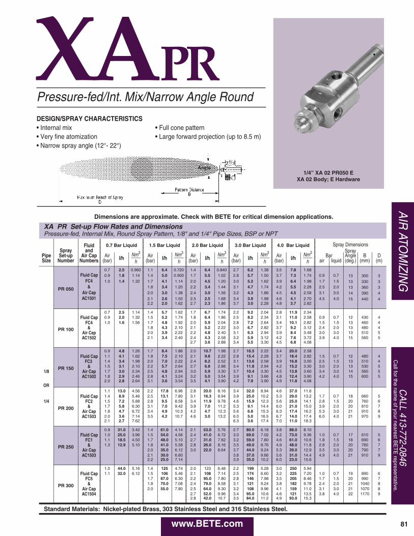
CA
LL 413-772-0846C
all for the name of your nearest B
ET
E representative.
www.BETE.com
XAPR
XA PR Set-up Flow Rates and DimensionsPressure-fed, Internal Mix, Round Spray Pattern, 1/8" and 1/4" Pipe Sizes, BSP or NPT
Fluid 0.7 Bar Liquid 1.5 Bar Liquid 2.0 Bar Liquid 3.0 Bar Liquid 4.0 Bar Liquid Spray DimensionsSpray and
Nm3
hNm3
hNm3
hNm3
hNm3
hPipe Set-up Air Cap Air l/h Air l/h Air l/h Air l/h Air l/h Bar
SprayB D
Size Number Numbers (bar) (bar) (bar) (bar) (bar) air liquid (deg.) (mm) (m)
0.7 2.5 0.960 1.1 6.4 0.720 1.4 6.4 0.840 2.7 6.2 1.38 3.5 7.8 1.68
PR 050
Fluid Cap 0.9 1.8 1.14 1.4 5.0 0.900 1.7 5.5 1.02 2.8 5.7 1.50 3.7 7.3 1.74 0.9 0.7 13 300 3FC4 1.0 1.4 1.32 1.7 4.1 1.14 2.0 4.5 1.20 3.0 5.2 1.62 3.9 6.4 1.98 1.7 1.5 13 330 3
& 1.8 3.4 1.20 2.2 3.4 1.44 3.1 4.7 1.74 4.2 5.5 2.28 2.5 2.0 13 360 3Air Cap 2.0 3.0 1.38 2.4 3.0 1.56 3.2 4.3 1.86 4.5 4.5 2.58 3.1 3.0 14 390 4AC1501 2.1 2.6 1.50 2.5 2.5 1.68 3.4 3.9 1.98 4.6 4.1 2.70 4.5 4.0 15 440 4
2.2 2.0 1.62 2.7 2.3 1.86 3.7 3.0 2.28 4.8 3.7 2.82
0.7 2.5 1.14 1.4 5.7 1.62 1.7 6.7 1.74 2.2 9.2 2.04 2.8 11.9 2.34
PR 100
Fluid Cap 0.9 2.0 1.32 1.5 5.2 1.74 1.8 6.4 1.86 2.5 8.2 2.34 3.1 11.0 2.58 0.9 0.7 12 430 4FC4 1.0 1.6 1.56 1.7 4.8 1.92 2.0 5.9 2.04 2.8 7.2 2.64 3.4 10.1 2.82 1.5 1.5 13 460 4
& 1.8 4.3 2.10 2.1 5.2 2.22 3.0 6.7 2.82 3.7 9.2 3.12 2.4 2.0 13 480 4Air Cap 2.0 3.9 2.22 2.2 4.8 2.40 3.1 6.3 2.94 3.9 8.4 3.48 3.0 3.0 13 510 5AC1502 2.1 3.4 2.40 2.4 4.3 2.58 3.2 5.9 3.12 4.2 7.6 3.72 3.9 4.0 15 560 5
2.7 3.6 2.88 3.4 5.5 3.30 4.5 6.8 4.08
0.9 4.8 1.26 1.7 8.4 1.86 2.0 10.7 1.98 2.7 16.5 2.22 3.4 20.0 2.58
PR 150
Fluid Cap 1.1 4.1 1.62 1.8 7.5 2.10 2.1 9.8 2.22 2.8 15.4 2.28 3.7 18.4 2.82 1.5 0.7 12 480 4FC3 1.4 3.4 1.98 2.0 7.0 2.22 2.4 8.2 2.52 3.1 13.6 2.58 3.9 16.8 3.00 2.5 1.5 13 510 4
& 1.5 3.1 2.10 2.2 5.7 2.64 2.7 6.8 2.88 3.4 11.8 2.94 4.2 15.2 3.30 3.0 2.0 13 530 51/8 Air Cap 1.7 3.0 2.34 2.5 4.8 2.94 3.0 5.9 3.30 3.7 10.4 3.30 4.5 13.8 3.60 3.4 3.0 14 560 5
AC1502 1.8 2.9 2.46 2.8 4.1 3.24 3.2 5.0 3.54 3.9 9.1 3.66 4.8 12.4 3.90 4.2 4.0 15 600 52.0 2.8 2.64 3.1 3.6 3.54 3.5 4.1 3.90 4.2 7.9 3.90 4.9 11.8 4.08
OR1.1 13.0 4.56 2.2 17.8 6.96 2.8 20.0 8.16 3.4 32.0 8.94 4.6 37.0 11.6
PR 200
Fluid Cap 1.4 8.9 5.46 2.5 13.1 7.80 3.1 16.3 8.94 3.9 25.0 10.2 5.3 29.0 13.2 1.7 0.7 18 660 51/4 FC2 1.5 7.2 5.88 2.8 9.5 8.58 3.4 11.9 9.78 4.6 15.9 12.3 5.6 25.0 14.1 2.8 1.5 20 760 6
& 1.7 5.8 6.30 3.1 7.0 9.42 3.9 7.0 11.2 5.3 9.1 14.4 6.0 21.0 15.0 3.9 2.0 20 810 7Air Cap 1.8 4.7 6.72 3.4 4.9 10.3 4.2 4.7 12.3 5.6 6.8 15.3 6.3 17.4 16.2 5.3 3.0 21 910 8AC1503 2.0 3.6 7.14 3.5 4.2 10.7 4.6 3.0 13.2 6.0 5.0 16.5 6.7 14.0 17.4 6.0 4.0 21 970 9
2.1 2.7 7.62 6.3 3.6 17.4 7.0 11.0 18.3
0.9 31.0 3.42 1.4 61.0 4.14 2.1 53.0 5.76 2.7 80.0 6.18 3.8 88.0 8.10
PR 250
Fluid Cap 1.0 25.0 3.96 1.5 54.0 4.56 2.4 41.0 6.72 3.0 69.0 7.02 4.2 73.0 9.36 1.0 0.7 17 610 5FC1 1.1 18.5 4.50 1.7 48.0 5.10 2.7 31.0 7.62 3.2 59.0 7.80 4.6 61.0 10.6 1.8 1.5 18 690 6
& 1.3 12.9 5.10 1.8 41.0 5.58 2.8 26.0 8.16 3.5 49.0 8.76 4.9 48.0 11.8 2.8 2.0 20 760 7Air Cap 2.0 35.0 6.12 3.0 22.0 8.64 3.7 44.0 9.24 5.3 39.0 12.9 3.5 3.0 20 790 7AC1503 2.1 30.0 6.60 3.8 37.0 9.66 5.6 31.0 14.4 4.9 4.0 21 910 9
2.2 25.0 7.14 3.9 35.0 10.2 6.0 23.0 15.6
1.0 44.0 5.16 1.4 125 4.74 2.0 123 6.48 2.2 199 5.28 3.0 250 5.94
PR 300
Fluid Cap 1.1 32.0 6.12 1.5 106 5.46 2.1 108 7.14 2.5 174 6.60 3.2 225 7.20 1.0 0.7 19 890 6FC5 1.7 87.0 6.30 2.2 95.0 7.80 2.8 146 7.98 3.5 205 8.46 1.7 1.5 20 990 7
& 1.8 70.0 7.08 2.4 79.0 8.58 3.1 121 9.24 3.8 182 9.78 2.4 2.0 21 1040 8Air Cap 2.0 55.0 7.80 2.5 64.0 9.30 3.2 108 9.96 4.1 159 11.0 3.1 3.0 21 1070 8AC1504 2.7 52.0 9.96 3.4 95.0 10.6 4.6 121 13.5 3.8 4.0 22 1170 9
2.8 42.0 10.7 3.5 84.0 11.2 4.9 93.0 15.3
Standard Materials: Nickel-plated Brass, 303 Stainless Steel and 316 Stainless Steel.
Angle
Pressure-fed/Int. Mix/Narrow Angle Round
DESIGN/SPRAY CHARACTERISTICS• Internal mix• Very fine atomization• Narrow spray angle (12°- 22°)
• Full cone pattern• Large forward projection (up to 8.5 m)
AIR
ATOM
IZING
1/4” XA 02 PR050 EXA 02 Body; E Hardware
81
Dimensions are approximate. Check with BETE for critical dimension applications.
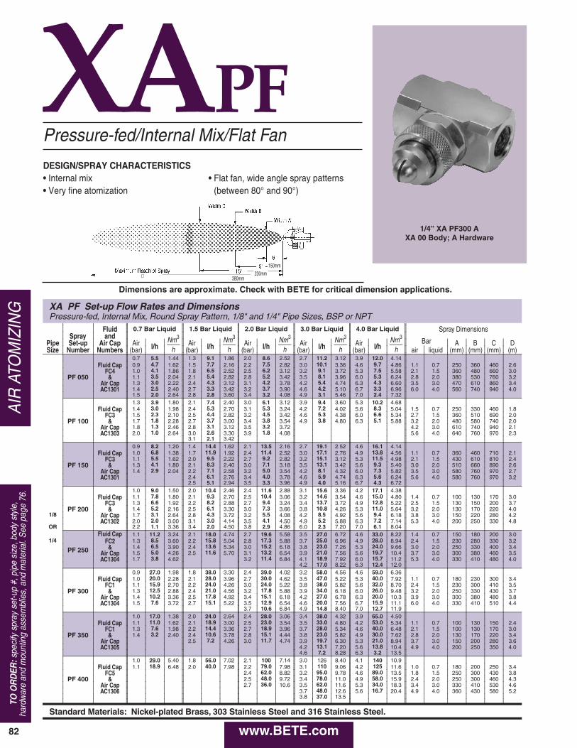
XAPF
XA PF Set-up Flow Rates and DimensionsPressure-fed, Internal Mix, Round Spray Pattern, 1/8" and 1/4" Pipe Sizes, BSP or NPT
Fluid 0.7 Bar Liquid 1.5 Bar Liquid 2.0 Bar Liquid 3.0 Bar Liquid 4.0 Bar Liquid Spray DimensionsSpray and Nm3
hNm3
hNm3
hNm3
hNm3
hPipe Set-up Air Cap Air l/h Air l/h Air l/h Air l/h Air l/h
Bar A B C DSize Number Numbers (bar) (bar) (bar) (bar) (bar) air liquid (mm) (mm) (mm) (m)
0.7 5.5 1.44 1.3 9.1 1.86 2.0 8.6 2.52 2.7 11.2 3.12 3.9 12.0 4.14
PF 050
Fluid Cap 0.9 4.7 1.62 1.5 7.7 2.16 2.2 7.5 2.82 3.0 10.1 3.36 4.6 9.7 4.86 1.1 0.7 250 360 460 2.6FC4 1.0 4.1 1.86 1.8 6.5 2.52 2.5 6.2 3.12 3.2 9.1 3.72 5.3 7.5 5.58 2.1 1.5 360 480 660 3.0
& 1.1 3.5 2.04 2.1 5.4 2.82 2.8 5.2 3.42 3.5 8.1 3.96 6.0 5.3 6.24 2.8 2.0 380 530 760 3.2Air Cap 1.3 3.0 2.22 2.4 4.3 3.12 3.1 4.2 3.78 4.2 5.4 4.74 6.3 4.3 6.60 3.5 3.0 470 610 860 3.4AC1301 1.4 2.5 2.40 2.7 3.3 3.42 3.2 3.7 3.90 4.6 4.2 5.10 6.7 3.3 6.96 6.0 4.0 560 740 940 4.0
1.5 2.0 2.64 2.8 2.8 3.60 3.4 3.2 4.08 4.9 3.1 5.46 7.0 2.4 7.321.3 3.9 1.80 2.1 7.4 2.40 3.0 6.1 3.12 3.9 9.4 3.60 5.3 10.2 4.68
PF 100
Fluid Cap 1.4 3.0 1.98 2.4 5.3 2.70 3.1 5.3 3.24 4.2 7.2 4.02 5.6 8.3 5.04 1.5 0.7 250 330 460 1.8FC3 1.5 2.3 2.10 2.5 4.4 2.82 3.2 4.5 3.42 4.6 5.3 4.38 6.0 6.6 5.34 2.7 1.5 360 510 690 2.0
& 1.7 1.8 2.28 2.7 3.7 3.00 3.4 3.8 3.54 4.9 3.8 4.80 6.3 5.1 5.88 3.2 2.0 480 580 740 2.0Air Cap 1.8 1.3 2.46 2.8 3.1 3.12 3.5 3.2 3.72 4.2 3.0 610 740 940 2.1AC1303 2.0 1.0 2.64 3.0 2.6 3.30 3.9 1.8 4.08 5.6 4.0 640 760 970 2.3
3.1 2.1 3.420.9 8.2 1.20 1.4 14.4 1.62 2.1 13.5 2.16 2.7 19.1 2.52 4.6 16.1 4.14
PF 150
Fluid Cap 1.0 6.8 1.38 1.7 11.9 1.92 2.4 11.4 2.52 3.0 17.1 2.76 4.9 13.8 4.56 1.1 0.7 360 460 710 2.1FC3 1.1 5.5 1.62 2.0 9.5 2.22 2.7 9.2 2.82 3.2 15.1 3.12 5.3 11.5 4.98 2.1 1.5 430 610 810 2.4
& 1.3 4.1 1.80 2.1 8.3 2.40 3.0 7.1 3.18 3.5 13.1 3.42 5.6 9.3 5.40 3.0 2.0 510 660 890 2.6Air Cap 1.4 2.9 2.04 2.2 7.1 2.58 3.2 5.0 3.54 4.2 8.1 4.32 6.0 7.3 5.82 3.5 3.0 580 760 970 2.7AC1301 2.4 6.1 2.76 3.4 4.0 3.78 4.6 5.9 4.74 6.3 5.6 6.24 5.6 4.0 580 760 970 3.2
2.5 5.1 2.94 3.5 3.3 3.96 4.9 4.0 5.16 6.7 4.3 6.721.0 9.0 1.50 2.0 10.4 2.46 2.4 11.6 2.88 3.1 15.6 3.36 4.2 17.1 4.38
PF 200
Fluid Cap 1.1 7.8 1.80 2.1 9.3 2.70 2.5 10.4 3.06 3.2 14.6 3.54 4.6 15.0 4.80 1.4 0.7 100 130 170 3.0FC3 1.3 6.6 1.92 2.2 8.2 2.88 2.7 9.4 3.24 3.4 13.7 3.72 4.9 12.8 5.22 2.5 1.5 130 150 200 3.7
& 1.4 5.2 2.16 2.5 6.1 3.30 3.0 7.3 3.66 3.8 10.8 4.26 5.3 11.0 5.64 3.2 2.0 130 170 220 4.01/8 Air Cap 1.7 3.1 2.64 2.8 4.3 3.72 3.2 5.5 4.08 4.2 8.5 4.92 5.6 9.4 6.18 3.8 3.0 150 220 280 4.2
AC1302 2.0 2.0 3.00 3.1 3.0 4.14 3.5 4.1 4.50 4.9 5.2 5.88 6.3 7.2 7.14 5.3 4.0 200 250 330 4.8OR 2.2 1.1 3.36 3.4 2.0 4.50 3.8 2.9 4.86 6.0 2.3 7.20 7.0 6.1 8.04
Fluid Cap 1.1 11.2 3.24 2.1 18.0 4.74 2.7 19.6 5.58 3.5 27.0 6.72 4.6 33.0 8.22 1.4 0.7 150 180 200 3.01/4
PF 250FC2 1.3 8.5 3.60 2.2 15.8 5.04 2.8 17.3 5.88 3.7 25.0 6.96 4.9 28.0 8.94 2.4 1.5 230 280 330 3.2
& 1.4 6.5 3.90 2.4 13.6 5.34 3.0 15.2 6.18 3.8 23.0 7.26 5.3 24.0 9.66 3.0 2.0 250 330 400 3.4Air Cap 1.5 5.0 4.26 2.5 11.6 5.70 3.1 13.2 6.54 3.9 21.0 7.56 5.6 19.7 10.4 3.7 3.0 300 380 460 3.5AC1304 1.7 3.8 4.62 3.2 11.4 6.84 4.1 18.9 7.92 6.0 15.7 11.2 5.3 4.0 330 410 480 4.0
4.2 17.0 8.22 6.3 12.4 12.00.9 27.0 1.98 1.8 38.0 3.30 2.4 39.0 4.02 3.2 58.0 4.56 4.6 59.0 6.36
PF 300
Fluid Cap 1.0 20.0 2.28 2.1 28.0 3.96 2.7 30.0 4.62 3.5 47.0 5.22 5.3 40.0 7.92 1.1 0.7 180 230 300 3.4FC1 1.1 15.9 2.70 2.2 24.0 4.26 3.0 24.0 5.22 3.8 38.0 5.82 5.6 32.0 8.70 2.4 1.5 230 300 410 3.5
& 1.3 12.5 2.88 2.4 21.0 4.56 3.2 17.8 5.88 3.9 34.0 6.18 6.0 26.0 9.48 3.2 2.0 250 330 430 3.7Air Cap 1.4 10.2 3.36 2.5 17.8 4.92 3.4 15.1 6.18 4.2 27.0 6.78 6.3 20.0 10.3 3.9 3.0 300 380 480 3.8AC1304 1.5 7.6 3.72 2.7 15.1 5.22 3.5 12.9 6.54 4.6 20.0 7.56 6.7 15.9 11.1 6.0 4.0 330 410 510 4.4
3.7 10.6 6.84 4.9 14.8 8.40 7.0 12.7 11.91.0 17.0 1.38 2.0 24.0 2.64 2.4 28.0 3.06 3.4 38.0 4.32 3.9 65.0 4.50
PF 350
Fluid Cap 1.1 11.0 1.62 2.1 18.9 3.00 2.5 23.0 3.54 3.5 33.0 4.80 4.2 53.0 5.34 1.1 0.7 100 130 150 2.4FC1 1.3 7.6 1.98 2.2 14.4 3.36 2.7 18.9 3.96 3.7 28.0 5.34 4.6 40.0 6.48 2.1 1.5 100 130 170 3.0
& 1.4 3.2 2.40 2.4 10.6 3.78 2.8 15.1 4.44 3.8 23.0 5.82 4.9 30.0 7.62 2.8 2.0 130 170 220 3.4Air Cap 2.5 7.2 4.26 3.0 11.7 4.74 3.9 19.7 6.30 5.3 21.0 8.94 3.7 3.0 150 200 280 3.6AC1305 4.2 13.1 7.20 5.6 13.8 10.4 4.9 4.0 200 250 350 4.0
4.6 7.2 8.28 6.3 3.2 13.51.0 29.0 5.40 1.8 56.0 7.02 2.1 100 7.14 3.0 126 8.40 4.1 140 10.9
PF 400
Fluid Cap 1.1 18.9 6.48 2.0 40.0 7.98 2.2 79.0 7.98 3.1 110 9.06 4.2 125 11.6 1.0 0.7 180 200 250 3.4FC5 2.4 62.0 8.82 3.2 95.0 9.78 4.6 89.0 13.5 1.8 1.5 250 300 430 3.8
& 2.5 48.0 9.72 3.4 78.0 11.0 4.9 58.0 15.9 2.4 2.0 250 300 460 4.3Air Cap 2.7 36.0 10.6 3.5 62.0 11.6 5.3 34.0 18.3 3.4 3.0 330 410 530 4.6AC1306 3.7 48.0 12.6 5.6 16.7 20.4 4.9 4.0 360 430 580 5.2
3.8 37.0 13.5
Standard Materials: Nickel-plated Brass, 303 Stainless Steel and 316 Stainless Steel.
Pressure-fed/Internal Mix/Flat Fan
• Flat fan, wide angle spray patterns(between 80° and 90°)
82
AIR
ATO
MIZ
ING
DESIGN/SPRAY CHARACTERISTICS• Internal mix• Very fine atomization
1/4” XA PF300 AXA 00 Body; A Hardware
TO O
RD
ER:s
peci
fy s
pray
set
-up
#, p
ipe
size
, bod
y st
yle,
hard
war
e an
d m
ount
ing
asse
mbl
ies,
and
mat
eria
l. S
ee p
age
76.
150mm230mm
380mm
Dimensions are approximate. Check with BETE for critical dimension applications.
www.BETE.com
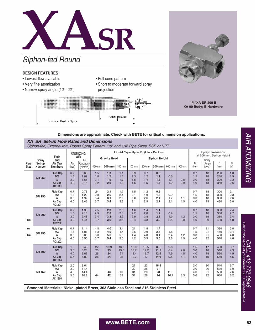
CA
LL 413-772-0846C
all for the name of your nearest B
ET
E representative.
XASR
XA SR Set-up Flow Rates and DimensionsSiphon-fed, External Mix, Round Spray Pattern, 1/8" and 1/4" Pipe Sizes, BSP or NPT
Liquid Capacity in l/h (Liters Per Hour) Spray Dimensions at 200 mm. Siphon Height
ATOMIZINGFluid AIR Gravity Head Siphon HeightSpray and Air Spray
Pipe Set-up Air Cap Air Capacity Air Angle B DSize Number Numbers (bar) (Nm3/h) 450 mm 300 mm 150 mm 100 mm 200 mm 300 mm 600 mm 900 mm (bar) (deg.) (mm) (m)
SR 050
Fluid Cap 0.7 0.66 1.5 1.3 1.1 0.9 0.7 0.5 0.7 18 280 1.8FC7 1.5 1.02 1.8 1.7 1.5 1.3 1.2 1.1 0.6 1.5 18 280 1.9
& 3.0 1.68 2.1 1.9 1.7 1.5 1.4 1.3 1.1 0.8 3.0 18 300 2.3Air Cap 4.0 2.16 2.2 2.0 1.8 1.6 1.5 1.4 1.2 0.9 4.0 18 360 2.6AC 1201
SR 150
Fluid Cap 0.7 0.78 24 2.1 1.7 1.5 1.2 0.8 0.7 18 300 2.1FC4 1.5 1.20 2.8 2.6 2.4 2.1 1.9 1.6 0.9 1.5 18 330 2.3
& 3.0 1.92 3.4 3.1 2.9 2.8 2.6 2.4 1.7 1.1 3.0 18 380 2.6Air Cap 4.0 2.46 3.7 3.4 3.3 3.1 2.9 2.7 2.1 1.5 4.0 19 430 3.0AC1201
SR 200
Fluid Cap 0.7 1.38 2.5 2.3 2.0 1.6 1.4 1.1 0.7 18 300 2.4FC4 1.5 2.16 2.9 2.8 2.5 2.2 2.0 1.7 0.9 1.5 18 330 2.7
& 3.0 3.48 3.4 3.3 3.2 2.9 2.8 2.5 1.9 1.2 3.0 19 380 3.41/8 Air Cap 4.0 4.44 3.7 3.6 3.5 3.4 3.3 3.0 2.5 2.0 4.0 20 430 4.0
AC1202
or
SR 250
Fluid Cap 0.7 1.14 4.5 4.0 3.4 21 1.8 1.4 0.7 21 380 3.0FC3 1.5 1.86 5.3 4.9 4.4 3.5 2.9 2.7 1.8 1.5 21 410 3.4
1/4 & 3.0 3.00 6.0 5.6 5.0 4.4 4.0 3.4 2.4 1.2 3.0 21 460 4.0Air Cap 4.0 3.90 5.7 5.4 5.0 4.2 3.9 3.5 2.8 1.9 4.0 22 510 4.6AC1202
SR 400
Fluid Cap 1.5 3.48 22 19.9 16.3 12.3 10.5 8.3 2.8 1.5 17 460 3.7FC1 3.0 5.28 25 23 19.5 16.7 14.2 11.5 6.4 2.8 3.0 18 510 4.3
& 4.0 6.66 26 24 21 18.4 15.7 12.9 7.9 4.5 4.0 18 530 4.9Air Cap 5.6 8.82 26 24 22 19.7 17 14.6 9.8 6.1 5.6 19 580 5.5AC 1204
SR 450
Fluid Cap 2.0 8.64 27 22 16.8 2.0 20 510 6.7FC5 3.0 11.4 30 26 21 3.0 20 530 7.0
& 4.0 14.4 43 40 31 28 23 11.0 4.0 21 580 7.6Air Cap 5.6 18.9 44 42 39 31 28 24 16.7 8.3 5.6 22 630 8.2AC 1205
Standard Materials: Nickel-plated Brass, 303 Stainless Steel and 316 Stainless Steel.
Siphon-fed Round
• Full cone pattern• Short to moderate forward spray
projection
AIR
ATOM
IZING
DESIGN FEATURES• Lowest flow available• Very fine atomization• Narrow spray angle (12°- 22°)
1/4”XA SR 200 BXA 00 Body; B Hardware
83
Dimensions are approximate. Check with BETE for critical dimension applications.
www.BETE.com
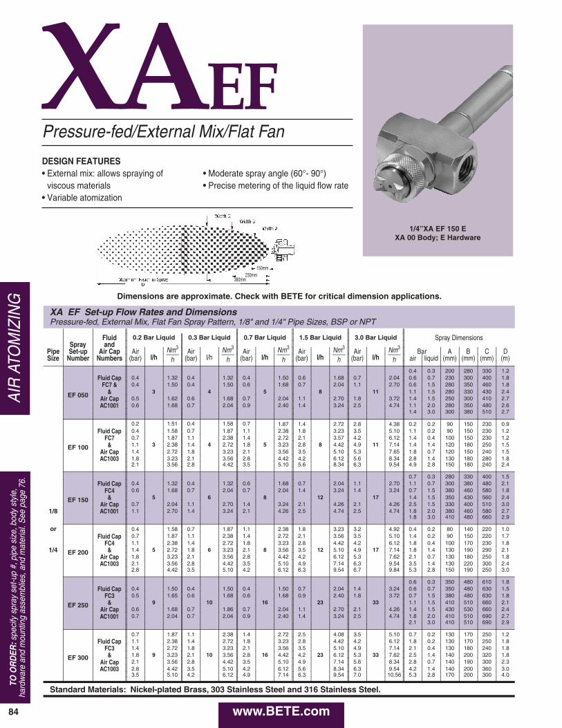
84
XAEF
XA EF Set-up Flow Rates and DimensionsPressure-fed, External Mix, Flat Fan Spray Pattern, 1/8" and 1/4" Pipe Sizes, BSP or NPT
Fluid 0.2 Bar Liquid 0.3 Bar Liquid 0.7 Bar Liquid 1.5 Bar Liquid 3.0 Bar Liquid Spray DimensionsSpray and
Nm3
hNm3
hNm3
hNm3
hNm3
hPipe Set-up Air Cap Air
l/hAir
l/hAir
l/hAir
l/hAir
l/hBar A B C D
Size Number Numbers (bar) (bar) (bar) (bar) (bar) air liquid (mm) (mm) (mm) (m)
0.4 0.3 200 280 330 1.2Fluid Cap 0.4 1.32 0.4 1.32 0.4 1.50 0.6 1.68 0.7 2.04 0.6 0.7 230 300 400 1.8
EF 050
FC7 & 0.4 1.50 0.4 1.50 0.6 1.68 0.7 2.04 1.1 2.70 0.6 1.5 280 350 460 1.8& 3 4 5 8 11 1.1 1.5 280 330 430 2.4
Air Cap 0.5 1.62 0.6 1.68 0.7 2.04 1.1 2.70 1.8 3.72 1.4 1.5 250 300 410 2.7AC1001 0.6 1.68 0.7 2.04 0.9 2.40 1.4 3.24 2.5 4.74 1.1 2.0 280 350 480 2.6
1.4 3.0 300 380 510 2.7
0.2 1.51 0.4 1.58 0.7 1.87 1.4 2.72 2.8 4.38 0.2 0.2 90 150 230 0.9
EF 100
Fluid Cap 0.4 1.58 0.7 1.87 1.1 2.38 1.8 3.23 3.5 5.10 1.1 0.2 90 150 230 1.2FC7 0.7 1.87 1.1 2.38 1.4 2.72 2.1 3.57 4.2 6.12 1.4 0.4 100 150 230 1.2
& 1.1 3 2.38 1.4 4 2.72 1.8 5 3.23 2.8 8 4.42 4.9 11 7.14 1.4 1.4 120 180 250 1.5Air Cap 1.4 2.72 1.8 3.23 2.1 3.56 3.5 5.10 5.3 7.65 1.8 0.7 120 150 240 1.5AC1003 1.8 3.23 2.1 3.56 2.8 4.42 4.2 6.12 5.6 8.34 2.8 1.4 130 180 280 1.8
2.1 3.56 2.8 4.42 3.5 5.10 5.6 8.34 6.3 9.54 4.9 2.8 150 180 240 2.4
0.7 0.3 280 330 400 1.5
EF 150
Fluid Cap 0.4 1.32 0.4 1.32 0.6 1.68 0.7 2.04 1.1 2.70 1.1 0.7 300 380 480 2.1FC4 0.6 1.68 0.7 2.04 0.7 2.04 1.4 3.24 1.4 3.24 0.7 1.5 380 460 580 1.8
& 5 6 8 12 17 1.4 1.5 350 430 560 2.4Air Cap 0.7 2.04 1.1 2.70 1.4 3.24 2.1 4.26 2.1 4.26 2.5 1.5 330 400 510 3.0
1/8 AC1001 1.1 2.70 1.4 3.24 2.1 4.26 2.5 4.74 2.5 4.74 1.8 2.0 380 460 580 2.71.8 3.0 410 480 660 2.9
or 0.4 1.58 0.7 1.87 1.1 2.38 1.8 3.23 3.2 4.92 0.4 0.2 80 140 220 1.0
EF 200
Fluid Cap 0.7 1.87 1.1 2.38 1.4 2.72 2.1 3.56 3.5 5.10 1.4 0.2 90 150 220 1.7FC4 1.1 2.38 1.4 2.72 1.8 3.23 2.8 4.42 4.2 6.12 1.8 0.4 100 170 230 1.8
1/4 & 1.4 5 2.72 1.8 6 3.23 2.1 8 3.56 3.5 12 5.10 4.9 17 7.14 1.8 1.4 130 190 290 2.1Air Cap 1.8 3.23 2.1 3.56 2.8 4.42 4.2 6.12 5.3 7.62 2.1 0.7 130 180 250 1.8AC1003 2.1 3.56 2.8 4.42 3.5 5.10 4.9 7.14 6.3 9.54 3.5 1.4 130 220 300 2.4
2.8 4.42 3.5 5.10 4.2 6.12 6.3 9.54 6.7 9.84 5.3 2.8 150 190 250 3.0
0.6 0.3 350 480 610 1.8
EF 250
Fluid Cap 0.4 1.50 0.4 1.50 0.4 1.50 0.7 2.04 1.4 3.24 0.6 0.7 350 480 630 1.5FC3 0.5 1.65 0.6 1.68 0.6 1.68 0.9 2.40 1.8 3.72 0.7 1.5 380 480 630 1.8
& 9 10 16 23 33 1.1 1.5 410 510 660 2.1Air Cap 0.6 1.68 0.7 1.86 0.7 2.04 1.1 2.70 2.1 4.26 1.4 1.5 430 530 660 2.4AC1001 0.7 2.04 0.7 2.04 0.9 2.40 1.4 3.24 2.5 4.74 1.8 2.0 410 510 690 2.7
2.1 3.0 410 510 690 2.9
0.7 1.87 1.1 2.38 1.4 2.72 2.5 4.08 3.5 5.10 0.7 0.2 130 170 250 1.2
EF 300
Fluid Cap 1.1 2.38 1.4 2.72 1.8 3.23 2.8 4.42 4.2 6.12 1.8 0.2 130 170 250 1.8FC3 1.4 2.72 1.8 3.23 2.1 3.56 3.5 5.10 4.9 7.14 2.1 0.4 130 180 240 1.8
& 1.8 9 3.23 2.1 10 3.56 2.8 16 4.42 4.2 23 6.12 5.3 33 7.62 2.5 1.4 140 200 320 1.8Air Cap 2.1 3.56 2.8 4.42 3.5 5.10 4.9 7.14 5.6 8.34 2.8 0.7 140 190 300 2.3AC1003 2.8 4.42 3.5 5.10 4.2 6.12 5.6 8.34 6.3 9.54 4.2 1.4 140 200 360 3.0
3.5 5.10 4.2 6.12 4.9 7.14 6.3 9.54 7.0 10.56 5.3 2.8 170 200 300 4.0
Standard Materials: Nickel-plated Brass, 303 Stainless Steel and 316 Stainless Steel.
Pressure-fed/External Mix/Flat Fan
• Moderate spray angle (60°- 90°)• Precise metering of the liquid flow rate
AIR
ATO
MIZ
ING
DESIGN FEATURES• External mix: allows spraying of
viscous materials• Variable atomization
1/4”XA EF 150 EXA 00 Body; E Hardware
TO O
RD
ER:s
peci
fy s
pray
set
-up
#, p
ipe
size
, bod
y st
yle,
hard
war
e an
d m
ount
ing
asse
mbl
ies,
and
mat
eria
l. S
ee p
age
76.
150mm230mm
380mm
Dimensions are approximate. Check with BETE for critical dimension applications.
www.BETE.com
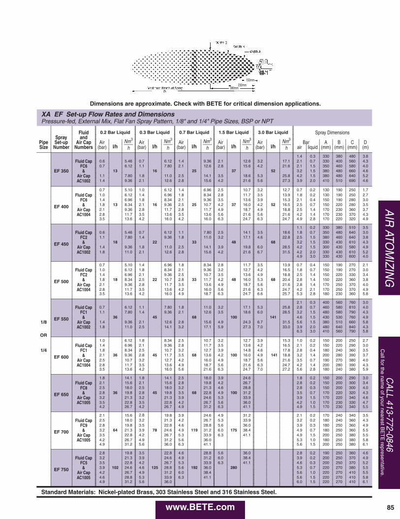
CA
LL 413-772-0846C
all for the name of your nearest B
ET
E representative.
XA EF Set-up Flow Rates and DimensionsPressure-fed, External Mix, Flat Fan Spray Pattern, 1/8" and 1/4" Pipe Sizes, BSP or NPT
Fluid 0.2 Bar Liquid 0.3 Bar Liquid 0.7 Bar Liquid 1.5 Bar Liquid 3.0 Bar Liquid Spray DimensionsSpray and
Nm3
hNm3
hNm3
hNm3
hNm3
hPipe Set-up Air Cap Air
l/hAir
l/hAir
l/hAir
l/hAir
l/hBar A B C D
Size Number Numbers (bar) (bar) (bar) (bar) (bar) air liquid (mm) (mm) (mm) (m)
1.4 0.3 330 380 480 3.8Fluid Cap 0.6 5.46 0.7 6.12 1.4 9.36 2.1 12.6 3.2 17.1 2.1 0.7 330 400 560 4.3
EF 350FC6 0.7 6.12 1.1 7.80 2.1 12.6 2.8 15.6 4.2 21.6 2.1 1.5 350 460 580 4.0& 13 16 25 37 52 3.2 1.5 380 480 660 4.6
Air Cap 1.1 7.80 1.8 11.0 2.5 14.1 3.5 18.6 5.3 25.8 4.2 1.5 380 480 640 5.2AC1002 1.4 9.36 2.1 12.6 2.8 15.6 4.2 21.6 5.6 27.3 3.9 2.0 410 510 690 4.6
0.7 5.10 1.0 6.12 1.4 6.96 2.5 10.7 3.2 12.7 0.7 0.2 130 190 250 1.7
EF 400
Fluid Cap 1.0 6.12 1.4 6.96 1.8 8.34 2.8 11.7 3.5 13.9 1.8 0.2 130 190 250 2.7FC6 1.4 6.96 1.8 8.34 2.1 9.36 3.5 13.6 3.9 15.3 2.1 0.4 150 190 280 3.0& 1.8 13 8.34 2.1 16 9.36 2.5 25 10.7 4.2 37 16.0 4.2 52 16.5 2.5 0.7 150 220 280 3.5
Air Cap 2.1 9.36 2.8 11.7 2.8 11.7 4.9 18.7 4.9 18.8 2.5 1.4 170 230 360 3.7AC1004 2.8 11.7 3.5 13.6 3.5 13.6 5.6 21.6 5.6 21.6 4.2 1.4 170 230 370 4.3
3.5 13.6 4.2 16.0 4.2 16.0 6.3 24.7 6.3 24.7 4.9 2.8 170 220 320 4.9
1.1 0.2 330 380 510 3.5
EF 450
Fluid Cap 0.6 5.46 0.7 6.12 1.1 7.80 2.5 14.1 3.5 18.6 1.8 0.7 350 480 640 3.0FC2 1.1 7.80 1.4 9.36 1.8 11.0 3.2 17.1 4.6 22.8 2.5 1.5 380 460 640 3.8& 18 22 33 48 68 3.2 1.5 330 430 610 4.3
Air Cap 1.4 9.36 1.8 11.0 2.5 14.1 3.9 19.8 6.0 28.5 4.2 1.5 300 430 580 4.9AC1002 1.8 11.0 2.1 12.6 2.8 15.6 4.2 21.6 6.7 31.5 4.2 2.0 330 430 610 5.2
4.9 3.0 330 430 600 4.0
0.7 5.10 1.4 6.96 1.8 8.34 2.8 11.7 3.5 13.9 0.7 0.4 150 190 270 2.1
EF 500
Fluid Cap 1.0 6.12 1.8 8.34 2.1 9.36 3.2 12.7 4.2 16.5 1.8 0.7 150 190 270 3.0FC2 1.4 6.96 2.1 9.36 2.5 10.7 3.5 13.6 4.9 18.8 2.5 1.4 150 220 330 3.4& 1.8 18 8.34 2.5 22 10.7 2.8 33 11.7 4.2 48 16.0 5.3 68 20.4 2.8 1.4 150 220 360 3.8
Air Cap 2.1 9.36 2.8 11.7 3.5 13.6 4.9 18.7 5.6 21.6 2.8 1.4 170 250 370 4.0AC1004 2.8 11.7 3.5 13.6 4.2 16.0 5.6 21.6 6.3 24.7 4.2 2.1 170 250 370 4.9
3.5 13.6 4.2 16.0 4.9 18.7 6.3 24.7 6.6 25.7 5.3 2.8 180 230 360 5.8
2.1 0.3 400 560 760 3.0
EF 550
Fluid Cap 0.7 6.12 1.1 7.80 1.8 11.0 3.2 17.1 5.3 25.8 2.8 0.7 460 580 810 4.0FC1 1.1 7.80 1.4 9.36 2.1 12.6 3.5 18.6 6.0 28.5 3.2 1.5 480 580 790 4.3& 36 45 68 100 141 4.6 1.5 430 530 760 4.9
1/8 Air Cap 1.4 9.36 2.1 12.6 2.8 15.6 4.9 24.3 6.7 31.5 5.6 1.5 380 510 660 5.8AC1002 1.8 11.0 2.5 14.1 3.2 17.1 5.9 27.3 7.0 33.0 3.9 2.0 480 640 840 4.3
6.3 3.0 410 560 790 5.8OR
1.0 6.12 1.8 8.34 2.5 10.7 3.2 12.7 3.9 15.3 1.0 0.2 150 200 250 2.7
EF 600
Fluid Cap 1.4 6.96 2.1 9.36 2.8 11.7 3.5 13.6 4.2 16.5 2.1 0.2 150 220 290 3.01/4 FC1 1.8 8.34 2.5 10.7 3.2 12.7 3.9 14.8 4.6 17.8 2.8 0.4 180 240 360 3.5
& 2.1 36 9.36 2.8 45 11.7 3.5 68 13.6 4.2 100 16.0 4.9 141 18.8 3.2 1.4 200 280 390 3.7Air Cap 2.5 10.7 3.2 12.7 4.2 16.0 4.9 18.7 5.6 21.6 3.5 0.7 190 270 380 4.0AC1004 2.8 11.7 3.5 13.6 4.9 18.7 5.6 21.6 6.3 24.7 4.2 1.4 200 280 390 4.3
3.5 13.6 4.2 16.0 5.6 21.6 6.3 24.7 7.0 27.2 5.6 2.8 180 240 380 5.9
1.8 14.1 1.8 14.1 2.5 18.0 3.9 24.6 1.8 0.2 150 200 290 3.0
EF 650
Fluid Cap 2.1 15.6 2.1 15.6 2.8 19.8 4.2 26.7 2.8 0.2 150 200 300 3.4FC8 2.5 18.0 2.5 18.0 3.2 21.3 4.6 28.8 2.8 0.3 150 200 300 4.0& 2.8 36 19.8 2.8 45 19.8 3.5 68 22.8 4.9 100 31.2 3.5 0.7 170 220 320 4.3
Air Cap 3.2 21.3 3.2 21.3 3.9 24.6 5.3 33.9 3.9 1.5 170 220 340 4.6AC1005 3.5 22.8 3.5 22.8 4.2 26.7 5.6 36.0 4.2 1.0 170 230 330 4.7
4.2 26.7 4.2 26.7 4.9 31.2 6.3 41.1 4.9 1.5 170 230 340 5.5
2.1 15.6 2.8 19.8 3.9 24.6 4.9 31.2 2.1 0.2 170 240 340 3.5
EF 700
Fluid Cap 2.5 18.0 3.2 21.3 4.2 26.7 5.3 33.9 3.2 0.2 180 240 360 4.3FC9 2.8 19.8 3.5 22.8 4.6 28.8 5.6 36.0 3.9 0.3 180 250 360 4.9& 3.2 64 21.3 3.9 78 24.6 4.9 119 31.2 6.0 175 38.4 4.9 0.7 180 250 360 5.5
Air Cap 3.5 22.8 4.2 26.7 5.3 33.9 6.3 41.1 4.9 1.5 200 250 380 5.5AC1005 4.2 26.7 4.9 31.2 5.6 36.0 5.3 1.0 180 250 380 5.8
4.9 31.2 5.6 36.0 6.3 41.1 5.6 1.5 200 250 380 6.1
2.8 19.8 3.5 22.8 4.6 28.8 5.6 36.0 2.8 0.2 190 250 360 4.6
EF 750
Fluid Cap 3.2 21.3 3.9 24.6 4.9 31.2 6.0 38.4 3.9 0.2 200 250 370 4.9FC5 3.5 22.8 4.2 26.7 5.3 33.9 6.3 41.1 4.6 0.3 200 250 370 5.2& 3.9 102 24.6 4.6 125 28.8 5.6 192 36.0 280 5.3 0.7 220 270 380 5.5
Air Cap 4.2 26.7 4.9 31.2 6.0 38.4 5.6 1.0 220 270 410 5.5AC1005 4.6 28.8 5.3 33.9 6.3 41.1 5.6 1.5 220 270 410 5.8
4.9 31.2 5.6 36.0 6.0 1.5 220 270 410 6.1
Standard Materials: Nickel-plated Brass, 303 Stainless Steel and 316 Stainless Steel.
AIR
ATOM
IZING
85
150mm230mm
380mm
Dimensions are approximate. Check with BETE for critical dimension applications.
www.BETE.com
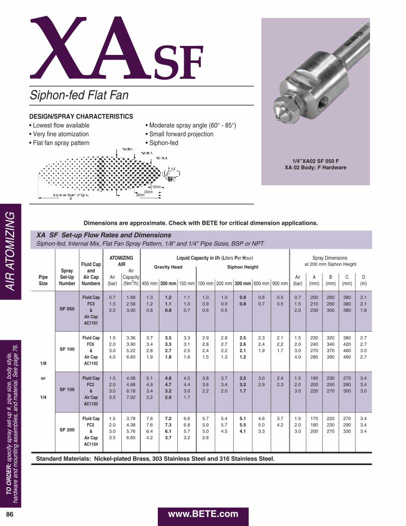
86
AIR
ATO
MIZ
ING
XASF
XA SF Set-up Flow Rates and DimensionsSiphon-fed, Internal Mix, Flat Fan Spray Pattern, 1/8" and 1/4" Pipe Sizes, BSP or NPT
ATOMIZING Liquid Capacity in l/h (Liters Per Hour) Spray Dimensions Fluid Cap AIR Gravity Head Siphon Height
at 200 mm Siphon Height
Spray and AirPipe Set-Up Air Cap Air Capacity Air A B C DSize Number Numbers (bar) (Nm3/h) 450 mm 300 mm 150 mm 100 mm 200 mm 300 mm 600 mm 900 mm (bar) (mm) (mm) (mm) (m)
SF 050
Fluid Cap 0.7 1.68 1.3 1.2 1.1 1.0 1.0 0.8 0.6 0.5 0.7 200 260 380 2.1FC3 1.5 2.58 1.2 1.1 1.0 0.9 0.9 0.8 0.7 0.5 1.5 210 290 380 2.1
& 2.0 3.00 0.8 0.8 0.7 0.6 0.5 2.0 230 300 380 1.8Air CapAC1101
SF 100
Fluid Cap 1.5 3.36 3.7 3.5 3.3 2.9 2.8 2.5 2.3 2.1 1.5 230 320 380 2.7FC6 2.0 3.90 3.4 3.3 3.1 2.8 2.7 2.6 2.4 2.2 2.0 240 340 420 2.7
& 3.0 5.22 2.8 2.7 2.5 2.4 2.2 2.1 1.9 1.7 3.0 270 370 460 3.0Air Cap 4.0 6.60 1.9 1.8 1.6 1.5 1.3 1.2 4.0 280 390 480 2.7
1/8 AC1102
or
SF 150
Fluid Cap 1.5 4.08 5.1 4.8 4.5 3.8 3.7 3.5 3.0 2.4 1.5 190 230 270 3.4FC2 2.0 4.68 4.9 4.7 4.4 3.6 3.4 3.2 2.9 2.3 2.0 200 250 280 3.4
& 3.0 6.18 3.4 3.2 3.0 2.2 2.0 1.7 3.0 220 270 300 3.01/4 Air Cap 3.5 7.02 2.2 2.0 1.7
AC1103
SF 200
Fluid Cap 1.5 3.78 7.6 7.2 6.6 5.7 5.4 5.1 4.6 3.7 1.5 170 220 270 3.4FC2 2.0 4.38 7.6 7.3 6.8 5.9 5.7 5.5 5.0 4.2 2.0 180 230 290 3.4
& 3.0 5.76 6.4 6.1 5.7 5.0 4.5 4.1 3.3 3.0 200 270 330 3.4Air Cap 3.5 6.60 4.2 3.7 3.2 2.6AC1104
Standard Materials: Nickel-plated Brass, 303 Stainless Steel and 316 Stainless Steel.
Siphon-fed Flat Fan
DESIGN/SPRAY CHARACTERISTICS• Lowest flow available• Very fine atomization• Flat fan spray pattern
• Moderate spray angle (60° - 85°)• Small forward projection• Siphon-fed
1/4”XA02 SF 050 FXA 02 Body; F Hardware
TO O
RD
ER:s
peci
fy s
pray
set
-up
#, p
ipe
size
, bod
y st
yle,
hard
war
e an
d m
ount
ing
asse
mbl
ies,
and
mat
eria
l. S
ee p
age
76.
150mm230mm
380mm
Dimensions are approximate. Check with BETE for critical dimension applications.
www.BETE.com
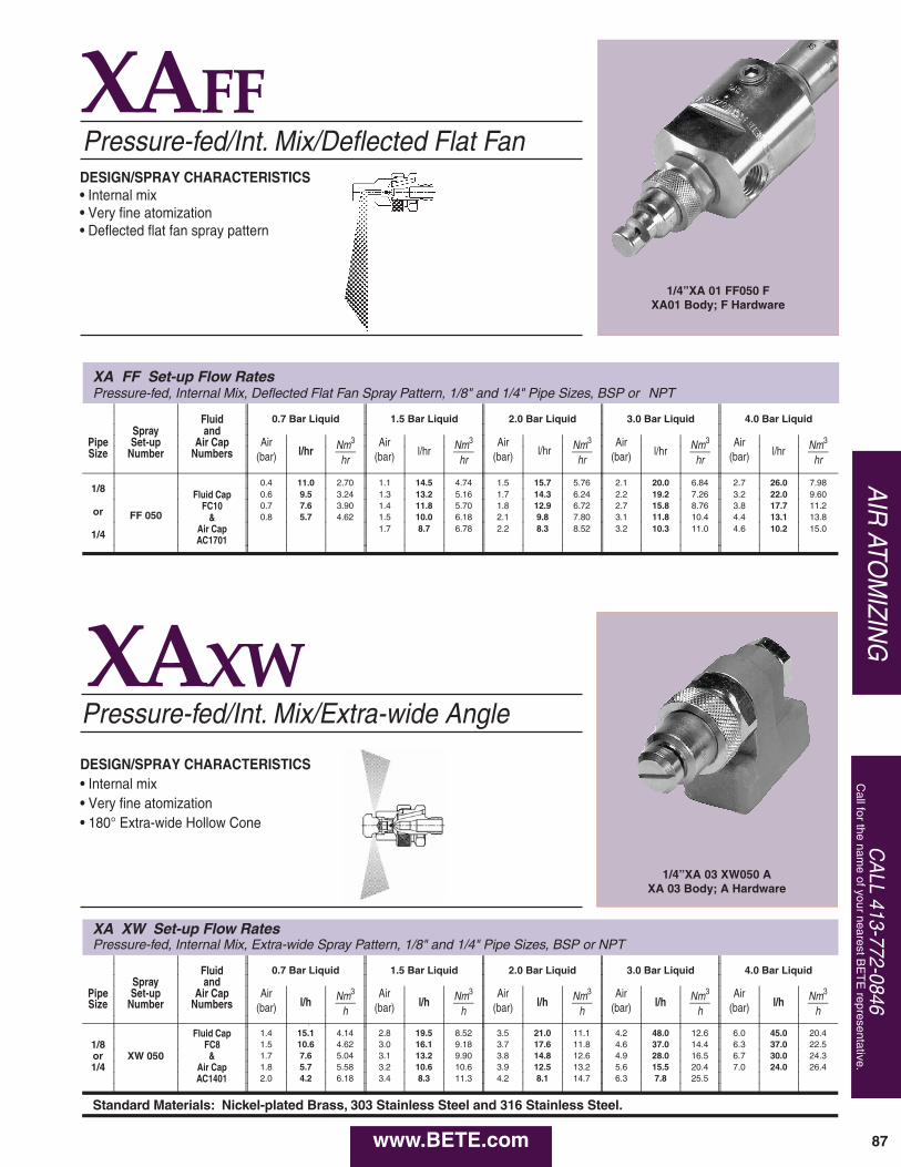
CA
LL 413-772-0846C
all for the name of your nearest B
ET
E representative.
AIR
ATOM
IZING
XAFFPressure-fed/Int. Mix/Deflected Flat Fan
XAXWPressure-fed/Int. Mix/Extra-wide Angle
DESIGN/SPRAY CHARACTERISTICS• Internal mix• Very fine atomization• 180° Extra-wide Hollow Cone
DESIGN/SPRAY CHARACTERISTICS• Internal mix• Very fine atomization• Deflected flat fan spray pattern
1/4”XA 01 FF050 FXA01 Body; F Hardware
1/4”XA 03 XW050 AXA 03 Body; A Hardware
87
XA FF Set-up Flow RatesPressure-fed, Internal Mix, Deflected Flat Fan Spray Pattern, 1/8" and 1/4" Pipe Sizes, BSP or NPT
Fluid 0.7 Bar Liquid 1.5 Bar Liquid 2.0 Bar Liquid 3.0 Bar Liquid 4.0 Bar LiquidSpray and
Pipe Set-up Air Cap Airl/hr Nm3
hr
Airl/hr Nm3
hr
Airl/hr Nm3
hr
Airl/hr Nm3
hr
Airl/hr Nm3
hrSize Number Numbers (bar) (bar) (bar) (bar) (bar)
1/8
FF 050
0.4 11.0 2.70 1.1 14.5 4.74 1.5 15.7 5.76 2.1 20.0 6.84 2.7 26.0 7.98Fluid Cap 0.6 9.5 3.24 1.3 13.2 5.16 1.7 14.3 6.24 2.2 19.2 7.26 3.2 22.0 9.60
or FC10 0.7 7.6 3.90 1.4 11.8 5.70 1.8 12.9 6.72 2.7 15.8 8.76 3.8 17.7 11.2& 0.8 5.7 4.62 1.5 10.0 6.18 2.1 9.8 7.80 3.1 11.8 10.4 4.4 13.1 13.8
1/4 Air Cap 1.7 8.7 6.78 2.2 8.3 8.52 3.2 10.3 11.0 4.6 10.2 15.0AC1701
XA XW Set-up Flow Rates Pressure-fed, Internal Mix, Extra-wide Spray Pattern, 1/8" and 1/4" Pipe Sizes, BSP or NPT
Fluid 0.7 Bar Liquid 1.5 Bar Liquid 2.0 Bar Liquid 3.0 Bar Liquid 4.0 Bar LiquidSpray and
Pipe Set-up Air Cap Airl/h Nm3
h
Airl/h Nm3
h
Airl/h Nm3
h
Airl/h Nm3
h
Airl/h Nm3
hSize Number Numbers (bar) (bar) (bar) (bar) (bar)1
Fluid Cap 1.4 15.1 4.14 2.8 19.5 8.52 3.5 21.0 11.1 4.2 48.0 12.6 6.0 45.0 20.41/8 FC8 1.5 10.6 4.62 3.0 16.1 9.18 3.7 17.6 11.8 4.6 37.0 14.4 6.3 37.0 22.5or XW 050 & 1.7 7.6 5.04 3.1 13.2 9.90 3.8 14.8 12.6 4.9 28.0 16.5 6.7 30.0 24.31/4 Air Cap 1.8 5.7 5.58 3.2 10.6 10.6 3.9 12.5 13.2 5.6 15.5 20.4 7.0 24.0 26.4
AC1401 2.0 4.2 6.18 3.4 8.3 11.3 4.2 8.1 14.7 6.3 7.8 25.5
Standard Materials: Nickel-plated Brass, 303 Stainless Steel and 316 Stainless Steel.
www.BETE.com
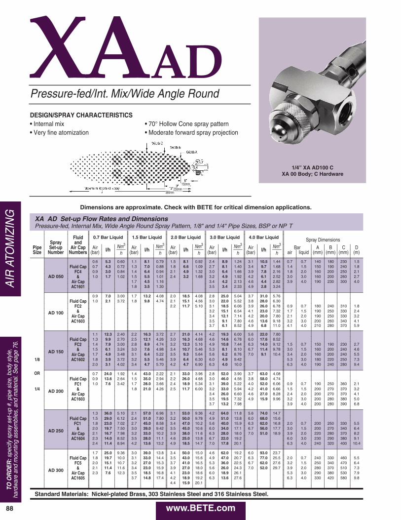
88
XAAD
XA AD Set-up Flow Rates and DimensionsPressure-fed, Internal Mix, Wide Angle Round Spray Pattern, 1/8" and 1/4" Pipe Sizes, BSP or NP T
Fluid 0.7 Bar Liquid 1.5 Bar Liquid 2.0 Bar Liquid 3.0 Bar Liquid 4.0 Bar Liquid Spray DimensionsSpray andNm3
hNm3
hNm3
hNm3
hNm3
hPipe Set-up Air Cap Air l/h Air l/h Air l/h Air l/h Air l/h Bar A B C DSize Number Numbers (bar) (bar) (bar) (bar) (bar) air liquid (mm) (mm) (mm) (m)
0.6 5.3 0.60 1.1 8.1 0.79 1.5 8.1 0.92 2.4 8.9 1.24 3.1 10.5 1.44 0.7 0.7 140 180 230 1.5
AD 050
Fluid Cap 0.7 4.3 0.72 1.3 7.0 0.88 1.8 6.6 1.09 2.7 8.1 1.40 3.4 9.7 1.68 1.4 1.5 150 190 240 1.8FC4 0.9 3.0 0.84 1.4 6.4 0.94 2.1 4.9 1.32 3.0 6.4 1.66 3.9 7.8 2.16 1.8 2.0 160 200 250 2.1
& 1.0 1.7 1.02 1.5 5.5 1.01 2.4 3.2 1.68 3.2 4.9 1.92 4.2 6.1 2.52 3.0 3.0 160 200 260 2.7Air Cap 1.7 4.5 1.16 3.4 4.2 2.13 4.6 4.4 2.82 3.9 4.0 190 230 300 4.0AC1601 1.8 3.5 1.30 3.5 3.4 2.33 4.9 2.8 3.24
0.9 7.0 3.00 1.7 13.2 4.08 2.0 18.5 4.08 2.8 25.0 5.04 3.7 31.0 5.76
AD 100
Fluid Cap 1.0 2.1 3.72 1.8 9.8 4.74 2.1 15.1 4.56 3.0 22.0 5.52 3.8 28.0 6.30FC2 2.2 11.7 5.10 3.1 18.5 6.06 3.9 26.0 6.78 0.9 0.7 180 240 310 1.8
& 3.2 15.1 6.54 4.1 23.0 7.32 1.7 1.5 190 250 330 2.4Air Cap 3.4 12.1 7.14 4.2 20.0 7.80 2.1 2.0 190 250 330 3.2AC1603 3.5 9.1 7.80 4.6 13.6 9.18 3.2 3.0 200 260 340 4.1
3.7 6.1 8.52 4.9 6.8 11.0 4.1 4.0 210 280 370 5.9
1.1 12.3 2.40 2.2 16.3 3.72 2.7 21.0 4.14 4.2 19.3 6.00 5.6 22.0 7.80
AD 150
Fluid Cap 1.3 9.9 2.70 2.5 12.1 4.26 3.0 16.3 4.68 4.6 14.6 6.78 6.0 17.6 8.52FC2 1.4 7.9 3.00 2.8 8.9 4.74 3.2 12.3 5.16 4.9 10.8 7.44 6.3 14.0 9.12 1.5 0.7 150 190 230 2.7
& 1.5 6.1 3.24 3.0 7.6 4.98 3.4 10.7 5.46 5.3 8.1 8.10 6.7 11.4 9.78 3.0 1.5 160 200 240 4.6Air Cap 1.7 4.9 3.48 3.1 6.4 5.22 3.5 9.3 5.64 5.6 6.2 8.76 7.0 9.1 10.4 3.4 2.0 160 200 240 5.5
1/8 AC1602 1.8 3.9 3.72 3.2 5.5 5.46 3.9 6.4 6.30 6.0 4.9 9.42 5.3 3.0 180 220 250 7.32.0 3.1 4.02 3.4 4.7 5.70 4.2 4.7 6.90 6.3 4.0 10.0 6.3 4.0 190 240 280 9.4
OR 0.7 24.0 1.92 1.4 43.0 2.22 2.1 33.0 3.96 2.8 52.0 3.90 3.7 63.0 4.08
AD 200
Fluid Cap 0.9 13.6 2.64 1.5 35.0 2.94 2.2 26.0 4.68 3.0 46.0 4.56 3.8 58.0 4.74FC1 1.0 7.6 3.42 1.7 28.0 3.66 2.4 18.9 5.34 3.1 39.0 5.22 4.0 52.0 6.06 0.9 0.7 190 250 360 2.1
1/4 & 1.8 21.0 4.26 2.5 11.7 6.00 3.2 33.0 5.94 4.2 41.0 6.66 1.5 1.5 200 270 370 3.2Air Cap 3.4 26.0 6.60 4.6 27.0 8.28 2.4 2.0 200 270 370 4.1AC1603 3.5 19.5 7.32 4.9 15.9 9.96 3.2 3.0 200 280 380 5.0
3.7 13.2 7.98 3.9 4.0 200 280 390 6.8
1.3 36.0 5.10 2.1 57.0 6.96 3.1 53.0 9.36 4.2 64.0 11.8 5.6 74.0 14.7
AD 250
Fluid Cap 1.5 29.0 6.12 2.4 51.0 7.80 3.2 50.0 9.78 4.9 51.0 13.8 6.0 68.0 15.6FC1 1.8 23.0 7.02 2.7 45.0 8.58 3.4 47.0 10.2 5.6 40.0 15.9 6.3 62.0 16.8 2.0 0.7 200 250 330 5.5
& 2.0 19.7 7.50 3.0 39.0 9.42 3.5 45.0 10.6 6.0 34.0 17.1 6.7 56.0 17.7 3.0 1.5 200 270 340 6.4Air Cap 2.1 16.7 7.98 3.2 33.0 10.2 3.9 38.0 11.6 6.3 28.0 18.0 7.0 51.0 18.9 3.9 2.0 220 280 370 8.2AC1604 2.3 14.0 8.52 3.5 28.0 11.1 4.6 25.0 13.8 6.7 22.0 19.2 6.0 3.0 230 290 380 9.1
2.4 11.4 8.94 4.2 13.6 13.2 4.9 18.5 14.7 7.0 17.8 20.1 6.3 4.0 240 320 400 10.4
1.7 25.0 9.36 3.0 39.0 13.8 3.4 50.0 15.0 4.6 62.0 19.2 6.0 93.0 23.7
AD 300
Fluid Cap 1.8 19.7 10.0 3.1 33.0 14.4 3.5 43.0 15.6 4.9 47.0 20.7 6.3 77.0 25.5 2.0 0.7 240 330 460 5.5FC5 2.0 15.1 10.7 3.2 27.0 15.3 3.7 41.0 16.5 5.3 36.0 22.5 6.7 62.0 27.6 3.2 1.5 250 340 470 6.4
& 2.1 11.4 11.6 3.4 23.0 15.9 3.9 27.0 18.0 5.6 26.0 24.3 7.0 52.0 29.7 3.9 2.0 280 370 510 7.3Air Cap 2.3 7.6 12.3 3.5 18.5 16.8 4.1 23.0 18.6 6.0 18.9 26.1 5.3 3.0 290 380 530 7.9AC1605 3.7 14.8 17.4 4.2 18.9 19.2 6.3 13.6 27.6 6.3 4.0 330 420 580 9.8
4.4 15.9 20.1
Standard Materials: Nickel-plated Brass, 303 Stainless Steel and 316 Stainless Steel.
Pressure-fed/Int. Mix/Wide Angle Round
• 70° Hollow Cone spray pattern• Moderate forward spray projection
DESIGN/SPRAY CHARACTERISTICS• Internal mix• Very fine atomization
AIR
ATO
MIZ
ING
TO O
RD
ER:s
peci
fy s
pray
set
-up
#, p
ipe
size
, bod
y st
yle,
hard
war
e an
d m
ount
ing
asse
mbl
ies,
and
mat
eria
l. S
ee p
age
76.
1/4” XA AD100 CXA 00 Body; C Hardware
150mm230mm
380mm
Dimensions are approximate. Check with BETE for critical dimension applications.
www.BETE.com
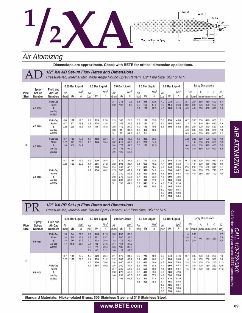
AD 1/2" XA AD Set-up Flow Rates and DimensionsPressure-fed, Internal Mix, Wide Angle Round Spray Pattern, 1/2" Pipe Size, BSP or NPT
Spray Fluid and0.35 Bar Liquid 1.0 Bar Liquid 2.0 Bar Liquid 3.0 Bar Liquid 4.0 Bar Liquid Spray Dimensions
Pipe Set-up Air Cap Airl/h
Nm3
hAir
l/hNm3
hAir
l/hNm3
hAir
l/hNm3
hAir
l/hNm3
h
bar A B C DSize Number Numbers (bar) (bar) (bar) (bar) (bar) air liquid (mm) (mm) (mm) (m)
1/2
AD 5050
Fluid Cap 2.1 213 10.6 3.1 316 12.8 4.2 238 21.1 2.1 2.0 360 480 690 6.7FC501 2.3 127 14.9 3.2 195 17.5 4.3 154 26.3 3.2 3.0 360 480 690 7.3
& 3.4 107 22.3 4.5 100 31.3 4.3 4.0 360 480 690 8.5Air CapAC5601
AD 5100
Fluid Cap 0.6 102 11.0 1.1 215 9.18 2.5 185 21.3 3.7 192 33.6 5.0 230 49.8 0.7 0.35 330 470 650 6.1FC501 0.7 57 13.8 1.3 124 13.8 2.7 146 24.6 3.9 150 37.2 5.3 158 56.4 1.3 1.0 340 480 670 7.9
& 0.85 32 16.8 1.4 84 16.8 2.8 112 27.9 4.0 119 40.8 5.6 108 64.8 2.8 2.0 330 470 650 6.4Air Cap 3.0 86 31.2 4.2 86 46.2 4.0 3.0 340 480 670 7.3AC5602 3.1 65 34.8 4.6 51 5.3 4.0 360 480 690 8.2
AD 5150
Fluid Cap 0.7 129 19.5 1.7 182 32.4 3.1 265 48.6 4.3 350 60.0 0.85 0.35 360 500 690 7.9FC501 0.85 82 22.2 1.8 143 35.4 3.2 215 51.6 4.6 260 64.8 1.7 1.0 330 480 660 7.3
& 1.0 45 24.9 3.4 173 54.6 5.0 186 72.0 3.4 2.0 330 470 660 7.0Air Cap 3.5 136 57.0 4.6 3.0 360 500 690 8.5AC5603 3.6 120 58.8
AD 5200
0.7 134 18.9 1.3 320 26.4 2.1 575 34.2 3.0 740 42.6 3.9 840 51.6 0.7 0.35 330 640 910 3.40.85 100 22.8 1.4 255 31.2 2.2 505 38.4 3.1 690 46.2 4.1 790 55.8 1.4 1.0 330 660 910 4.9
1.5 200 35.4 2.4 440 43.2 3.2 630 50.4 4.2 740 59.4 2.5 2.0 280 560 810 6.1Fluid Cap 1.7 154 40.2 2.5 380 47.4 3.4 570 54.6 4.4 690 64.2 3.4 3.0 280 530 740 6.7
FC502 2.7 330 51.6 3.5 520 58.8 4.5 650 68.4 4.5 4.0 280 560 790 7.6& 2.8 275 55.8 3.7 470 63.0 4.6 600 72.6
Air Cap 3.0 235 60.6 3.8 420 67.2 4.8 550 76.8AC5604 3.1 195 64.8 3.9 345 71.4 4.9 510 81.0
4.1 325 75.6 5.1 465 85.85.2 425 89.45.3 390 93.65.5 350 98.4
PR 1/2" XA PR Set-up Flow Rates and DimensionsPressure-fed, Internal Mix, Round Spray Pattern, 1/2" Pipe Size, BSP or NPT
Spray Fluid and0.35 Bar Liquid 1.0 Bar Liquid 2.0 Bar Liquid 3.0 Bar Liquid 4.0 Bar Liquid Spray Dimensions
Pipe Set-up Air Cap Airl/h
Nm3
hAir
l/hNm3
hAir
l/hNm3
hAir
l/hNm3
hAir
l/hNm3
h
bar A B C DSize Number Numbers (bar) (bar) (bar) (bar) (bar) air liquid (mm) (mm) (mm) (m)
1/2
PR 5050
Fluid Cap 1.3 34 21.0 1.7 146 21.9 3.0 230 30.6 1.4 0.35
90 160 250
6.7FC501 1.4 25 23.4 1.8 121 23.7 3.1 200 33.0 2.0 1.0 7.3
& 1.5 20 24.9 2.0 102 25.8 3.2 176 35.4 3.2 2.0 8.2Air Cap 1.7 15.5 26.7 2.1 86 27.6 3.4 154 37.2AC5501 2.3 72 29.4 3.5 135 39.6
2.4 60 31.2 3.6 118 42.0
PR 5100
0.7 134 18.9 1.3 320 26.4 2.1 575 34.2 3.0 740 42.6 3.9 840 51.6 0.7 0.35 100 180 230 7.00.85 100 22.8 1.4 255 31.2 2.2 505 38.4 3.1 690 46.2 4.1 790 55.8 1.4 1.0 150 250 330 6.4
1.5 200 35.4 2.4 440 43.2 3.2 630 50.4 4.2 740 59.4 2.5 2.0 130 200 250 11.3Fluid Cap 1.7 154 40.2 2.5 380 47.4 3.4 570 54.6 4.4 690 64.2 3.4 3.0 100 180 250 12.5
FC502 2.7 330 51.6 3.5 520 58.8 4.5 650 68.4 4.5 4.0 100 180 250 14.3& 2.8 275 55.8 3.7 470 63.0 4.6 600 72.6
Air Cap 3.0 235 60.6 3.8 420 67.2 4.8 550 76.8AC5502 3.1 195 64.8 3.9 345 71.4 4.9 510 81.0
4.1 325 75.6 5.1 465 85.85.2 425 89.45.3 390 93.65.5 350 98.4
Standard Materials: Nickel-plated Brass, 303 Stainless Steel and 316 Stainless Steel.
Air Atomizing
AIR
ATOM
IZING
CA
LL 413-772-0846C
all for the name of your nearest B
ET
E representative.
89
230mm
457mm686mm
1/2XADimensions are approximate. Check with BETE for critical dimension applications.
www.BETE.com
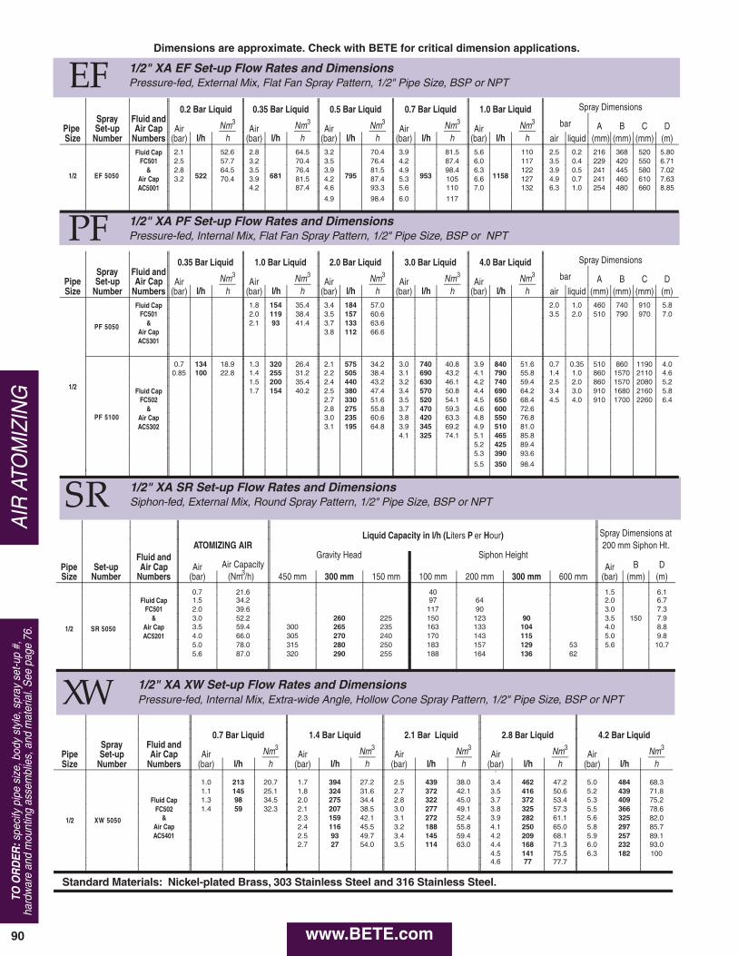
90
AIR
ATO
MIZ
ING
TO O
RD
ER:s
peci
fy p
ipe
size
, bod
y st
yle,
spr
ay s
et-u
p #,
hard
war
e an
d m
ount
ing
asse
mbl
ies,
and
mat
eria
l. S
ee p
age
76.
EF 1/2" XA EF Set-up Flow Rates and DimensionsPressure-fed, External Mix, Flat Fan Spray Pattern, 1/2" Pipe Size, BSP or NPT
Spray Fluid and0.2 Bar Liquid 0.35 Bar Liquid 0.5 Bar Liquid 0.7 Bar Liquid 1.0 Bar Liquid Spray Dimensions
Pipe Set-up Air Cap Airl/h
Nm3
hAir
l/hNm3
hAir
l/hNm3
hAir
l/hNm3
hAir
l/hNm3
h
bar A B C DSize Number Numbers (bar) (bar) (bar) (bar) (bar) air liquid (mm) (mm) (mm) (m)
1/2 EF 5050
Fluid Cap 2.1
522
52.6 2.8
681
64.5 3.2
795
70.4 3.9
953
81.5 5.6
1158
110 2.5 0.2 216 368 520 5.80FC501 2.5 57.7 3.2 70.4 3.5 76.4 4.2 87.4 6.0 117 3.5 0.4 229 420 550 6.71
& 2.8 64.5 3.5 76.4 3.9 81.5 4.9 98.4 6.3 122 3.9 0.5 241 445 580 7.02Air Cap 3.2 70.4 3.9 81.5 4.2 87.4 5.3 105 6.6 127 4.9 0.7 241 460 610 7.63AC5001 4.2 87.4 4.6 93.3 5.6 110 7.0 132 6.3 1.0 254 480 660 8.85
4.9 98.4 6.0 117
PF 1/2" XA PF Set-up Flow Rates and DimensionsPressure-fed, Internal Mix, Flat Fan Spray Pattern, 1/2" Pipe Size, BSP or NPT
Spray Fluid and0.35 Bar Liquid 1.0 Bar Liquid 2.0 Bar Liquid 3.0 Bar Liquid 4.0 Bar Liquid Spray Dimensions
Pipe Set-up Air Cap Airl/h
Nm3
hAir
l/hNm3
hAir
l/hNm3
hAir
l/hNm3
hAir
l/hNm3
h
bar A B C DSize Number Numbers (bar) (bar) (bar) (bar) (bar) air liquid (mm) (mm) (mm) (m)
1/2
PF 5050
Fluid Cap 1.8 154 35.4 3.4 184 57.0 2.0 1.0 460 740 910 5.8FC501 2.0 119 38.4 3.5 157 60.6 3.5 2.0 510 790 970 7.0
& 2.1 93 41.4 3.7 133 63.6Air Cap 3.8 112 66.6AC5301
PF 5100
0.7 134 18.9 1.3 320 26.4 2.1 575 34.2 3.0 740 40.8 3.9 840 51.6 0.7 0.35 510 860 1190 4.00.85 100 22.8 1.4 255 31.2 2.2 505 38.4 3.1 690 43.2 4.1 790 55.8 1.4 1.0 860 1570 2110 4.6
1.5 200 35.4 2.4 440 43.2 3.2 630 46.1 4.2 740 59.4 2.5 2.0 860 1570 2080 5.2Fluid Cap 1.7 154 40.2 2.5 380 47.4 3.4 570 50.8 4.4 690 64.2 3.4 3.0 910 1680 2160 5.8
FC502 2.7 330 51.6 3.5 520 54.1 4.5 650 68.4 4.5 4.0 910 1700 2260 6.4& 2.8 275 55.8 3.7 470 59.3 4.6 600 72.6
Air Cap 3.0 235 60.6 3.8 420 63.3 4.8 550 76.8AC5302 3.1 195 64.8 3.9 345 69.2 4.9 510 81.0
4.1 325 74.1 5.1 465 85.85.2 425 89.45.3 390 93.6
5.5 350 98.4
SR 1/2" XA SR Set-up Flow Rates and DimensionsSiphon-fed, External Mix, Round Spray Pattern, 1/2" Pipe Size, BSP or NPT
Liquid Capacity in l/h (Liters P er Hour) Spray Dimensions at
Fluid andATOMIZING AIR
Gravity Head Siphon Height200 mm Siphon Ht.
Pipe Set-up Air Cap Air Air Capacity Air B DSize Number Numbers (bar) (Nm3/h) 450 mm 300 mm 150 mm 100 mm 200 mm 300 mm 600 mm (bar) (mm) (m)
1/2 SR 5050
0.7 21.6 40 1.5
150
6.1Fluid Cap 1.5 34.2 97 64 2.0 6.7
FC501 2.0 39.6 117 90 3.0 7.3& 3.0 52.2 260 225 150 123 90 3.5 7.9
Air Cap 3.5 59.4 300 265 235 163 133 104 4.0 8.8AC5201 4.0 66.0 305 270 240 170 143 115 5.0 9.8
5.0 78.0 315 280 250 183 157 129 53 5.6 10.75.6 87.0 320 290 255 188 164 136 62
XW 1/2" XA XW Set-up Flow Rates and DimensionsPressure-fed, Internal Mix, Extra-wide Angle, Hollow Cone Spray Pattern, 1/2" Pipe Size, BSP or NPT
Spray Fluid and0.7 Bar Liquid 1.4 Bar Liquid 2.1 Bar Liquid 2.8 Bar Liquid 4.2 Bar Liquid
Pipe Set-up Air Cap Airl/h
Nm3
hAir
l/hNm3
hAir
l/hNm3
hAir
l/hNm3
hAir
l/hNm3
hSize Number Numbers (bar) (bar) (bar) (bar) (bar)3
1/2 XW 5050
1.0 213 20.7 1.7 394 27.2 2.5 439 38.0 3.4 462 47.2 5.0 484 68.31.1 145 25.1 1.8 324 31.6 2.7 372 42.1 3.5 416 50.6 5.2 439 71.8
Fluid Cap 1.3 98 34.5 2.0 275 34.4 2.8 322 45.0 3.7 372 53.4 5.3 409 75.2FC502 1.4 59 32.3 2.1 207 38.5 3.0 277 49.1 3.8 325 57.3 5.5 366 78.6
& 2.3 159 42.1 3.1 272 52.4 3.9 282 61.1 5.6 325 82.0Air Cap 2.4 116 45.5 3.2 188 55.8 4.1 250 65.0 5.8 297 85.7AC5401 2.5 93 49.7 3.4 145 59.4 4.2 209 68.1 5.9 257 89.1
2.7 27 54.0 3.5 114 63.0 4.4 168 71.3 6.0 232 93.04.5 141 75.5 6.3 182 1004.6 77 77.7
Standard Materials: Nickel-plated Brass, 303 Stainless Steel and 316 Stainless Steel.
Dimensions are approximate. Check with BETE for critical dimension applications.
www.BETE.com
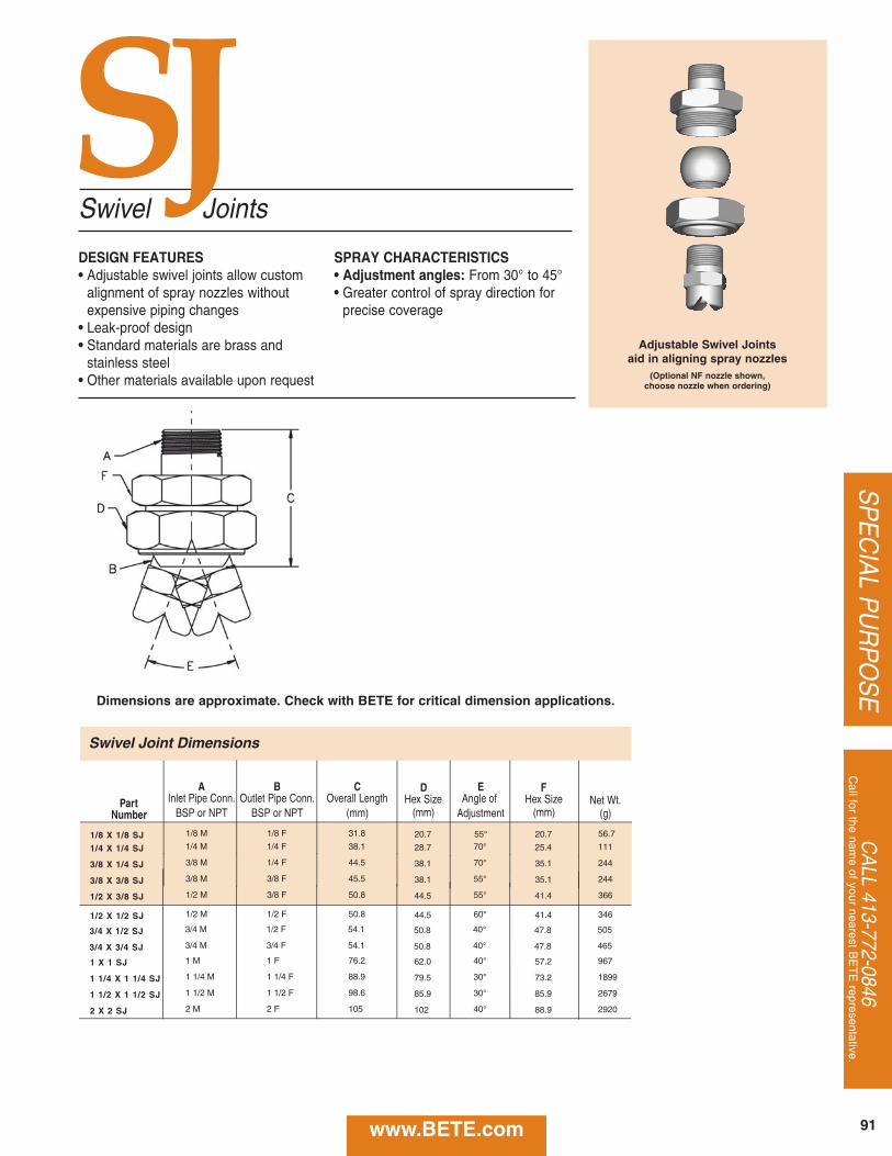
CA
LL 413-772-0846C
all for the name of your nearest B
ET
E representative.
SP
EC
IAL P
UR
PO
SE
91www.BETE.com
Swivel Joints
DESIGN FEATURES• Adjustable swivel joints allow custom
alignment of spray nozzles withoutexpensive piping changes
• Leak-proof design• Standard materials are brass and
stainless steel• Other materials available upon request
SPRAY CHARACTERISTICS• Adjustment angles: From 30° to 45°• Greater control of spray direction for
precise coverage
Adjustable Swivel Jointsaid in aligning spray nozzles
(Optional NF nozzle shown, choose nozzle when ordering)
Swivel Joint Dimensions
A B C D EPart Inlet Pipe Conn. Outlet Pipe Conn. Overall Length Hex Size Angle of Net Wt.
Number BSP or NPT BSP or NPT (mm) (mm) Adjustment (g)
1/4 X 1/4 SJ 1/4 M 1/4 F 38.1 28.7 70°
3/8 X 1/4 SJ 3/8 M 1/4 F 44.5 38.1 70°
3/8 X 3/8 SJ 3/8 M 3/8 F 45.5 38.1 55°
1/2 X 3/8 SJ 1/2 M 3/8 F 50.8 44.5 55°
1/2 X 1/2 SJ 1/2 M 1/2 F 50.8 44.5 60°
3/4 X 1/2 SJ 3/4 M 1/2 F 54.1 50.8 40°
3/4 X 3/4 SJ 3/4 M 3/4 F 54.1 50.8 40°
1/8 X 1/8 SJ 1/8 M 1/8 F 31.8 20.7 55°
1 X 1 SJ 1 M 1 F 76.2 62.0 40°
1 1/4 X 1 1/4 SJ 1 1/4 M 1 1/4 F 88.9 79.5 30°
1 1/2 X 1 1/2 SJ 1 1/2 M 1 1/2 F 98.6 85.9 30°
2 X 2 SJ 2 M 2 F 105 102 40°
FHex Size
(mm)
25.4
35.1
35.1
41.4
41.4
47.8
47.8
20.7
57.2
73.2
85.9
88.9
111
244
244
366
346
505
465
56.7
967
1899
2679
2920
SJ
Dimensions are approximate. Check with BETE for critical dimension applications.
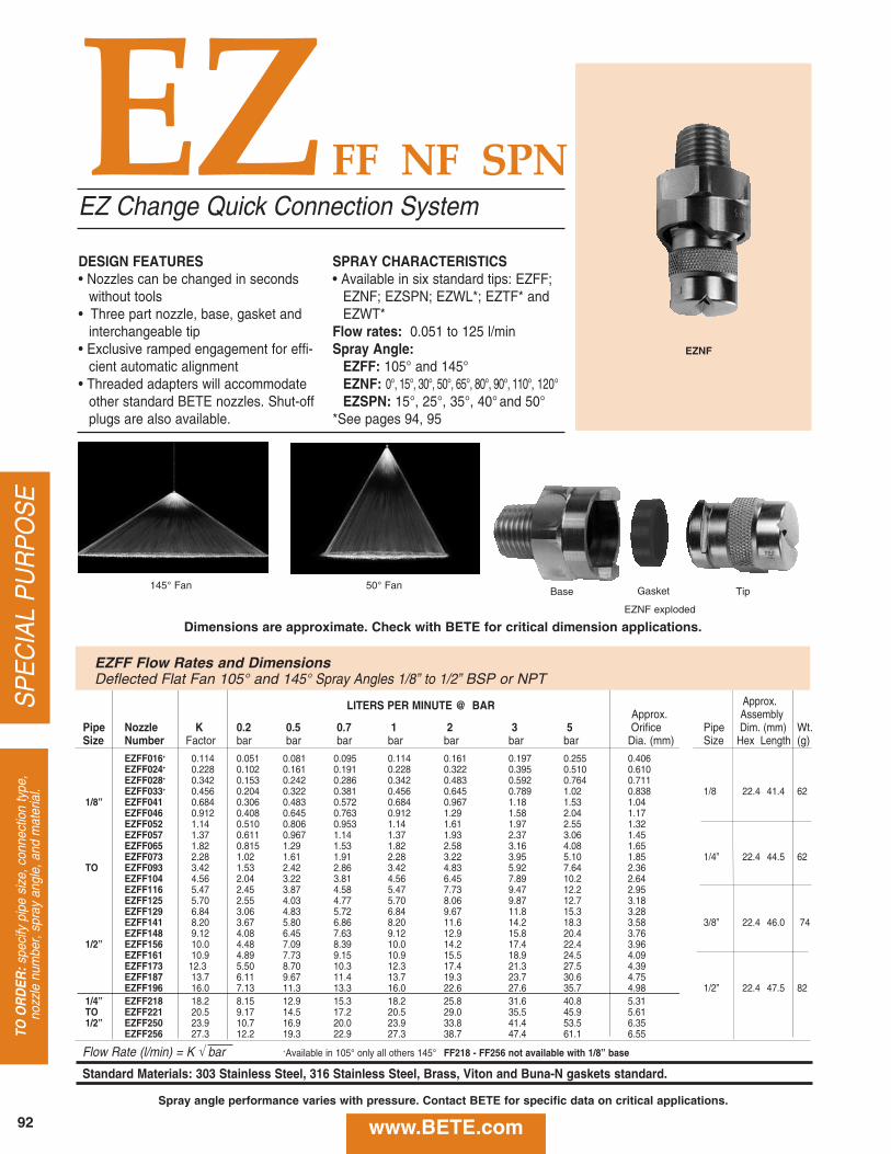
EZFF NF SPN
LITERS PER MINUTE @ BAR Approx.Approx. Assembly
Pipe Nozzle K 0.2 0.5 0.7 1 2 3 5 Orifice Pipe Dim. (mm) Wt.Size Number Factor bar bar bar bar bar bar bar Dia. (mm) Size Hex Length (g)
EZFF016+ 0.114 0.051 0.081 0.095 0.114 0.161 0.197 0.255 0.406EZFF024+ 0.228 0.102 0.161 0.191 0.228 0.322 0.395 0.510 0.610EZFF028+ 0.342 0.153 0.242 0.286 0.342 0.483 0.592 0.764 0.711EZFF033+ 0.456 0.204 0.322 0.381 0.456 0.645 0.789 1.02 0.838 1/8 22.4 41.4 62
1/8” EZFF041 0.684 0.306 0.483 0.572 0.684 0.967 1.18 1.53 1.04EZFF046 0.912 0.408 0.645 0.763 0.912 1.29 1.58 2.04 1.17EZFF052 1.14 0.510 0.806 0.953 1.14 1.61 1.97 2.55 1.32EZFF057 1.37 0.611 0.967 1.14 1.37 1.93 2.37 3.06 1.45EZFF065 1.82 0.815 1.29 1.53 1.82 2.58 3.16 4.08 1.65EZFF073 2.28 1.02 1.61 1.91 2.28 3.22 3.95 5.10 1.85 1/4” 22.4 44.5 62
TO EZFF093 3.42 1.53 2.42 2.86 3.42 4.83 5.92 7.64 2.36EZFF104 4.56 2.04 3.22 3.81 4.56 6.45 7.89 10.2 2.64EZFF116 5.47 2.45 3.87 4.58 5.47 7.73 9.47 12.2 2.95EZFF125 5.70 2.55 4.03 4.77 5.70 8.06 9.87 12.7 3.18EZFF129 6.84 3.06 4.83 5.72 6.84 9.67 11.8 15.3 3.28EZFF141 8.20 3.67 5.80 6.86 8.20 11.6 14.2 18.3 3.58 3/8” 22.4 46.0 74EZFF148 9.12 4.08 6.45 7.63 9.12 12.9 15.8 20.4 3.76
1/2” EZFF156 10.0 4.48 7.09 8.39 10.0 14.2 17.4 22.4 3.96EZFF161 10.9 4.89 7.73 9.15 10.9 15.5 18.9 24.5 4.09EZFF173 12.3 5.50 8.70 10.3 12.3 17.4 21.3 27.5 4.39EZFF187 13.7 6.11 9.67 11.4 13.7 19.3 23.7 30.6 4.75EZFF196 16.0 7.13 11.3 13.3 16.0 22.6 27.6 35.7 4.98 1/2” 22.4 47.5 82
1/4” EZFF218 18.2 8.15 12.9 15.3 18.2 25.8 31.6 40.8 5.31 TO EZFF221 20.5 9.17 14.5 17.2 20.5 29.0 35.5 45.9 5.611/2” EZFF250 23.9 10.7 16.9 20.0 23.9 33.8 41.4 53.5 6.35
EZFF256 27.3 12.2 19.3 22.9 27.3 38.7 47.4 61.1 6.55
Flow Rate (l/min) = K √ bar +Available in 105° only all others 145° FF218 - FF256 not available with 1/8” base
Standard Materials: 303 Stainless Steel, 316 Stainless Steel, Brass, Viton and Buna-N gaskets standard.
DESIGN FEATURES• Nozzles can be changed in seconds
without tools• Three part nozzle, base, gasket and
interchangeable tip• Exclusive ramped engagement for effi-
cient automatic alignment • Threaded adapters will accommodate
other standard BETE nozzles. Shut-offplugs are also available.
SPRAY CHARACTERISTICS• Available in six standard tips: EZFF;
EZNF; EZSPN; EZWL*; EZTF* andEZWT*
Flow rates: 0.051 to 125 l/minSpray Angle:
EZFF: 105° and 145°EZNF: 0°, 15°, 30°, 50°, 65°, 80°, 90°, 110°, 120°EZSPN: 15°, 25°, 35°, 40° and 50°
*See pages 94, 95
EZ Change Quick Connection System
145° Fan 50° Fan
EZFF Flow Rates and DimensionsDeflected Flat Fan 105° and 145° Spray Angles 1/8” to 1/2” BSP or NPT
SP
EC
IAL
PU
RP
OS
ETO
OR
DER
:spe
cify
pip
e si
ze, c
onne
ctio
n ty
pe,
nozz
le n
umbe
r, sp
ray
angl
e, a
nd m
ater
ial.
EZNF
EZNF exploded
Base Gasket Tip
Dimensions are approximate. Check with BETE for critical dimension applications.
www.BETE.com92
Spray angle performance varies with pressure. Contact BETE for specific data on critical applications.
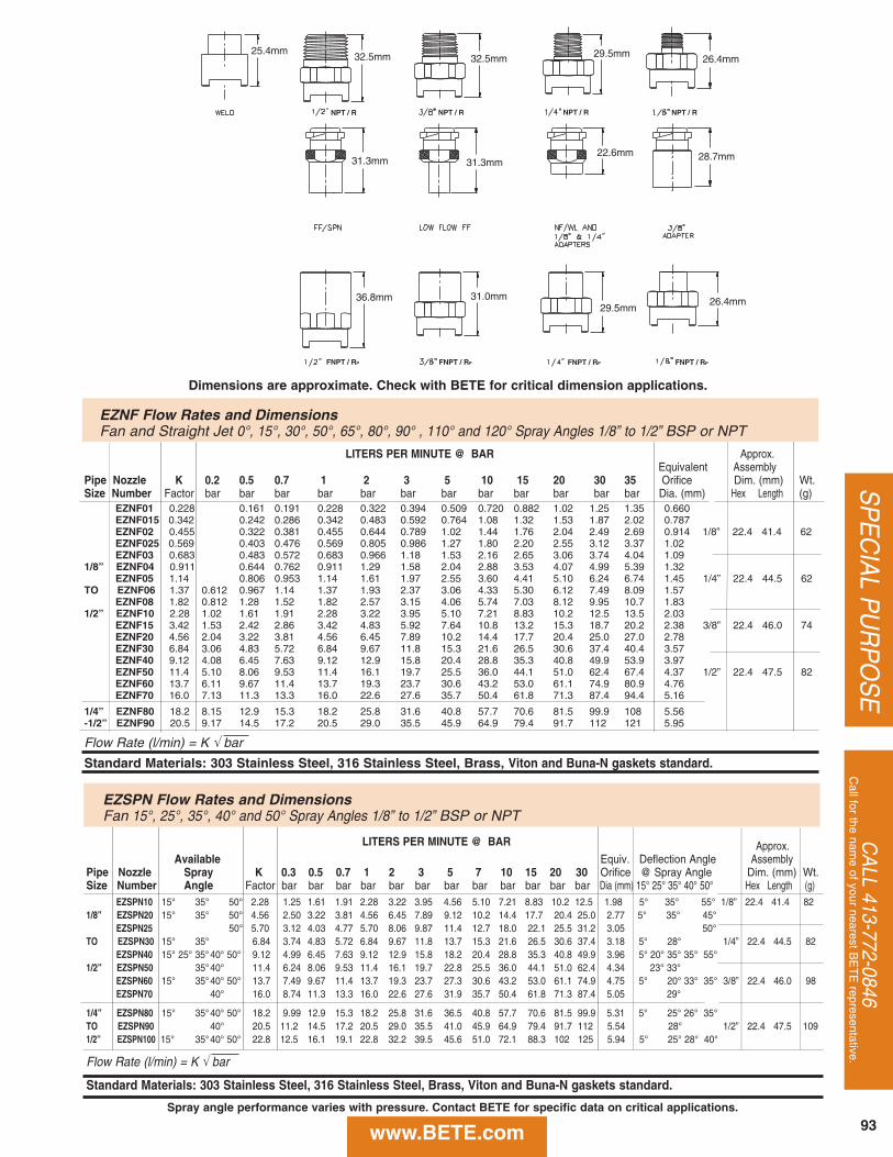
CA
LL 413-772-0846C
all for the name of your nearest B
ET
E representative.
SP
EC
IAL P
UR
PO
SE
LITERS PER MINUTE @ BAR Approx.Equivalent Assembly
Pipe Nozzle K 0.2 0.5 0.7 1 2 3 5 10 15 20 30 35 Orifice Dim. (mm) Wt.Size Number Factor bar bar bar bar bar bar bar bar bar bar bar bar Dia. (mm) Hex Length (g)
EZNF01 0.228 0.161 0.191 0.228 0.322 0.394 0.509 0.720 0.882 1.02 1.25 1.35 0.660EZNF015 0.342 0.242 0.286 0.342 0.483 0.592 0.764 1.08 1.32 1.53 1.87 2.02 0.787EZNF02 0.455 0.322 0.381 0.455 0.644 0.789 1.02 1.44 1.76 2.04 2.49 2.69 0.914 1/8” 22.4 41.4 62EZNF025 0.569 0.403 0.476 0.569 0.805 0.986 1.27 1.80 2.20 2.55 3.12 3.37 1.02EZNF03 0.683 0.483 0.572 0.683 0.966 1.18 1.53 2.16 2.65 3.06 3.74 4.04 1.09
1/8” EZNF04 0.911 0.644 0.762 0.911 1.29 1.58 2.04 2.88 3.53 4.07 4.99 5.39 1.32EZNF05 1.14 0.806 0.953 1.14 1.61 1.97 2.55 3.60 4.41 5.10 6.24 6.74 1.45 1/4” 22.4 44.5 62
TO EZNF06 1.37 0.612 0.967 1.14 1.37 1.93 2.37 3.06 4.33 5.30 6.12 7.49 8.09 1.57EZNF08 1.82 0.812 1.28 1.52 1.82 2.57 3.15 4.06 5.74 7.03 8.12 9.95 10.7 1.83
1/2” EZNF10 2.28 1.02 1.61 1.91 2.28 3.22 3.95 5.10 7.21 8.83 10.2 12.5 13.5 2.03EZNF15 3.42 1.53 2.42 2.86 3.42 4.83 5.92 7.64 10.8 13.2 15.3 18.7 20.2 2.38 3/8” 22.4 46.0 74EZNF20 4.56 2.04 3.22 3.81 4.56 6.45 7.89 10.2 14.4 17.7 20.4 25.0 27.0 2.78EZNF30 6.84 3.06 4.83 5.72 6.84 9.67 11.8 15.3 21.6 26.5 30.6 37.4 40.4 3.57EZNF40 9.12 4.08 6.45 7.63 9.12 12.9 15.8 20.4 28.8 35.3 40.8 49.9 53.9 3.97EZNF50 11.4 5.10 8.06 9.53 11.4 16.1 19.7 25.5 36.0 44.1 51.0 62.4 67.4 4.37 1/2” 22.4 47.5 82EZNF60 13.7 6.11 9.67 11.4 13.7 19.3 23.7 30.6 43.2 53.0 61.1 74.9 80.9 4.76EZNF70 16.0 7.13 11.3 13.3 16.0 22.6 27.6 35.7 50.4 61.8 71.3 87.4 94.4 5.16
1/4” EZNF80 18.2 8.15 12.9 15.3 18.2 25.8 31.6 40.8 57.7 70.6 81.5 99.9 108 5.56-1/2” EZNF90 20.5 9.17 14.5 17.2 20.5 29.0 35.5 45.9 64.9 79.4 91.7 112 121 5.95
Flow Rate (l/min) = K √ bar
Standard Materials: 303 Stainless Steel, 316 Stainless Steel, Brass, Viton and Buna-N gaskets standard.
EZNF Flow Rates and DimensionsFan and Straight Jet 0°, 15°, 30°, 50°, 65°, 80°, 90° , 110° and 120° Spray Angles 1/8” to 1/2” BSP or NPT
FNPT / RP FNPT / RP
NPT / RNPT / RNPT / R
FNPT / RP
NPT / R
FNPT / RP
25.4mm32.5mm 32.5mm
31.3mm 31.3mm
29.5mm 26.4mm
28.7mm22.6mm
36.8mm 31.0mm29.5mm
26.4mm
LITERS PER MINUTE @ BAR Approx.Available Equiv. Deflection Angle Assembly
Pipe Nozzle Spray K 0.3 0.5 0.7 1 2 3 5 7 10 15 20 30 Orifice @ Spray Angle Dim. (mm) Wt.Size Number Angle Factor bar bar bar bar bar bar bar bar bar bar bar bar Dia (mm) 15° 25° 35° 40° 50° Hex Length (g)
EZSPN10 15° 35° 50° 2.28 1.25 1.61 1.91 2.28 3.22 3.95 4.56 5.10 7.21 8.83 10.2 12.5 1.98 5° 35° 55° 1/8” 22.4 41.4 821/8” EZSPN20 15° 35° 50° 4.56 2.50 3.22 3.81 4.56 6.45 7.89 9.12 10.2 14.4 17.7 20.4 25.0 2.77 5° 35° 45°
EZSPN25 50° 5.70 3.12 4.03 4.77 5.70 8.06 9.87 11.4 12.7 18.0 22.1 25.5 31.2 3.05 50°TO EZSPN30 15° 35° 6.84 3.74 4.83 5.72 6.84 9.67 11.8 13.7 15.3 21.6 26.5 30.6 37.4 3.18 5° 28° 1/4” 22.4 44.5 82
EZSPN40 15° 25° 35° 40° 50° 9.12 4.99 6.45 7.63 9.12 12.9 15.8 18.2 20.4 28.8 35.3 40.8 49.9 3.96 5° 20° 35° 35° 55°1/2” EZSPN50 35°40° 11.4 6.24 8.06 9.53 11.4 16.1 19.7 22.8 25.5 36.0 44.1 51.0 62.4 4.34 23° 33°
EZSPN60 15° 35°40° 50° 13.7 7.49 9.67 11.4 13.7 19.3 23.7 27.3 30.6 43.2 53.0 61.1 74.9 4.75 5° 20° 33° 35° 3/8” 22.4 46.0 98EZSPN70 40° 16.0 8.74 11.3 13.3 16.0 22.6 27.6 31.9 35.7 50.4 61.8 71.3 87.4 5.05 29°
1/4” EZSPN80 15° 35°40° 50° 18.2 9.99 12.9 15.3 18.2 25.8 31.6 36.5 40.8 57.7 70.6 81.5 99.9 5.31 5° 25° 26° 35°TO EZSPN90 40° 20.5 11.2 14.5 17.2 20.5 29.0 35.5 41.0 45.9 64.9 79.4 91.7 112 5.54 28° 1/2” 22.4 47.5 1091/2” EZSPN100 15° 35°40° 50° 22.8 12.5 16.1 19.1 22.8 32.2 39.5 45.6 51.0 72.1 88.3 102 125 5.94 5° 25° 28° 40°
Flow Rate (l/min) = K √ bar
Standard Materials: 303 Stainless Steel, 316 Stainless Steel, Brass, Viton and Buna-N gaskets standard.
Dimensions are approximate. Check with BETE for critical dimension applications.
www.BETE.com 93
EZSPN Flow Rates and DimensionsFan 15°, 25°, 35°, 40° and 50° Spray Angles 1/8” to 1/2” BSP or NPT
Spray angle performance varies with pressure. Contact BETE for specific data on critical applications.
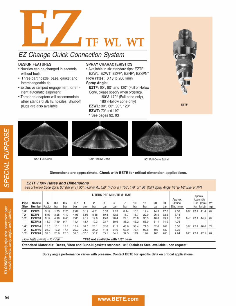
EZTF WL WT
SP
EC
IAL
PU
RP
OS
ETO
OR
DER
:spe
cify
pip
e si
ze, c
onne
ctio
n ty
pe,
nozz
le n
umbe
r, sp
ray
angl
e, a
nd m
ater
ial.
LITERS PER MINUTE @ BAR Approx.Approx. Assembly
Pipe Nozzle K 0.3 0.5 0.7 1 2 3 5 7 10 15 20 30 Orifice Dim. (mm) Wt.Size Number Factor bar bar bar bar bar bar bar bar bar bar bar bar Dia. (mm) Hex Length (g)
1/8” EZTF6 3.19 1.75 2.26 2.67 3.19 4.51 5.53 7.13 8.44 10.1 12.4 14.3 17.5 2.38 1/8” 22.4 41.4 62TO EZTF8 5.93 3.25 4.19 4.96 5.93 8.38 10.3 13.2 15.7 18.7 22.9 26.5 32.5 3.181/2” EZTF10 9.12 4.99 6.45 7.63 9.12 12.9 15.8 20.4 24.1 28.8 35.3 40.8 49.9 3.97 1/4” 22.4 44.5 62
EZTF12 13.7 7.49 9.7 11.4 13.7 19.3 23.7 30.6 36.2 43.2 53.0 61.1 74.9 4.76
1/4” EZTF14 18.5 10.1 13.1 15.4 18.5 26.1 32.0 41.3 48.8 58.4 71.5 82.6 101 5.56 3/8” 22.4 46.0 74TO EZTF16 24.2 13.2 17.1 20.2 24.2 34.2 41.8 54.0 63.9 76.4 93.6 108 132 6.351/2” EZTF20 37.6 20.6 26.6 31.5 37.6 53.2 65.1 84.1 99.5 119 146 168 206 7.94 1/2” 22.4 47.5 82
Flow Rate (l/min) = K √ bar TF20 not available with 1/8” base
Standard Materials: Brass, Viton and Buna-N gaskets standard. 316 Stainless Steel available upon request.
DESIGN FEATURES• Nozzles can be changed in seconds
without tools• Three part nozzle, base, gasket and
interchangeable tip• Exclusive ramped engagement for effi-
cient automatic alignment • Threaded adapters will accommodate
other standard BETE nozzles. Shut-offplugs are also available
SPRAY CHARACTERISTICS• Available in six standard tips: EZTF;
EZWL; EZWT; EZFF*; EZNF*; EZSPN*Flow rates: 0.13 to 206 l/minSpray Angle:
EZTF: 60°, 90° and 120° (Full or HollowCone, please specify when ordering),
150°& 170° (Full cone only),180°(Hollow cone only)
EZWL: 30°, 60°, 90°, 120°EZWT: 70° and 110°* See pages 92, 93
EZ Change Quick Connection System
EZTF
120° Full Cone 120° Hollow Cone 90° Full Cone Spiral
Dimensions are approximate. Check with BETE for critical dimension applications.
www.BETE.com94
Spray angle performance varies with pressure. Contact BETE for specific data on critical applications.
EZTF Flow Rates and DimensionsFull or Hollow Cone Spiral 60° (NN or V), 90° (FCN or M), 120° (FC or W), 150°, 170° or 180° (XW) Spray Angle 1/8” to 1/2” BSP or NPT
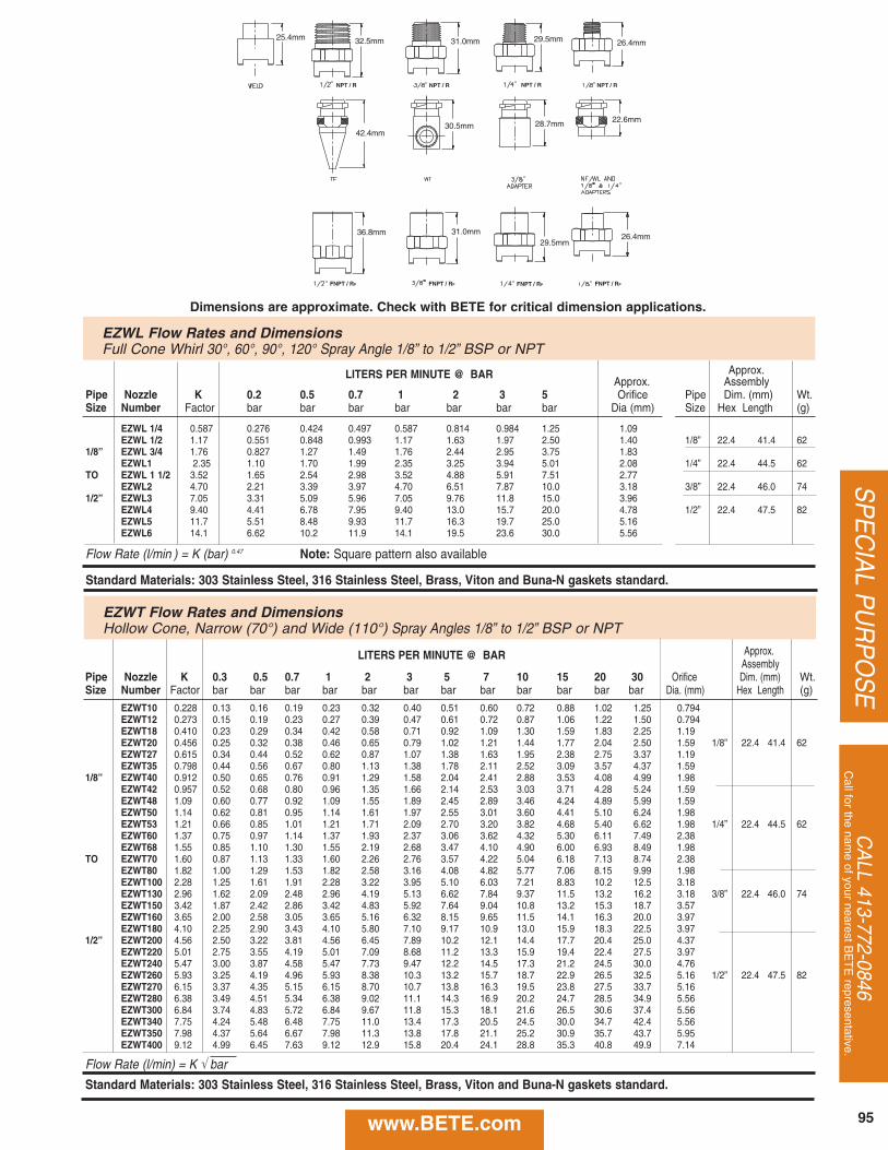
LITERS PER MINUTE @ BAR Approx.Assembly
Pipe Nozzle K 0.3 0.5 0.7 1 2 3 5 7 10 15 20 30 Orifice Dim. (mm) Wt.Size Number Factor bar bar bar bar bar bar bar bar bar bar bar bar Dia. (mm) Hex Length (g)
EZWT10 0.228 0.13 0.16 0.19 0.23 0.32 0.40 0.51 0.60 0.72 0.88 1.02 1.25 0.794EZWT12 0.273 0.15 0.19 0.23 0.27 0.39 0.47 0.61 0.72 0.87 1.06 1.22 1.50 0.794EZWT18 0.410 0.23 0.29 0.34 0.42 0.58 0.71 0.92 1.09 1.30 1.59 1.83 2.25 1.19EZWT20 0.456 0.25 0.32 0.38 0.46 0.65 0.79 1.02 1.21 1.44 1.77 2.04 2.50 1.59 1/8” 22.4 41.4 62EZWT27 0.615 0.34 0.44 0.52 0.62 0.87 1.07 1.38 1.63 1.95 2.38 2.75 3.37 1.19EZWT35 0.798 0.44 0.56 0.67 0.80 1.13 1.38 1.78 2.11 2.52 3.09 3.57 4.37 1.59
1/8” EZWT40 0.912 0.50 0.65 0.76 0.91 1.29 1.58 2.04 2.41 2.88 3.53 4.08 4.99 1.98EZWT42 0.957 0.52 0.68 0.80 0.96 1.35 1.66 2.14 2.53 3.03 3.71 4.28 5.24 1.59EZWT48 1.09 0.60 0.77 0.92 1.09 1.55 1.89 2.45 2.89 3.46 4.24 4.89 5.99 1.59EZWT50 1.14 0.62 0.81 0.95 1.14 1.61 1.97 2.55 3.01 3.60 4.41 5.10 6.24 1.98EZWT53 1.21 0.66 0.85 1.01 1.21 1.71 2.09 2.70 3.20 3.82 4.68 5.40 6.62 1.98 1/4” 22.4 44.5 62EZWT60 1.37 0.75 0.97 1.14 1.37 1.93 2.37 3.06 3.62 4.32 5.30 6.11 7.49 2.38EZWT68 1.55 0.85 1.10 1.30 1.55 2.19 2.68 3.47 4.10 4.90 6.00 6.93 8.49 1.98
TO EZWT70 1.60 0.87 1.13 1.33 1.60 2.26 2.76 3.57 4.22 5.04 6.18 7.13 8.74 2.38EZWT80 1.82 1.00 1.29 1.53 1.82 2.58 3.16 4.08 4.82 5.77 7.06 8.15 9.99 1.98EZWT100 2.28 1.25 1.61 1.91 2.28 3.22 3.95 5.10 6.03 7.21 8.83 10.2 12.5 3.18EZWT130 2.96 1.62 2.09 2.48 2.96 4.19 5.13 6.62 7.84 9.37 11.5 13.2 16.2 3.18 3/8” 22.4 46.0 74EZWT150 3.42 1.87 2.42 2.86 3.42 4.83 5.92 7.64 9.04 10.8 13.2 15.3 18.7 3.57EZWT160 3.65 2.00 2.58 3.05 3.65 5.16 6.32 8.15 9.65 11.5 14.1 16.3 20.0 3.97EZWT180 4.10 2.25 2.90 3.43 4.10 5.80 7.10 9.17 10.9 13.0 15.9 18.3 22.5 3.97
1/2” EZWT200 4.56 2.50 3.22 3.81 4.56 6.45 7.89 10.2 12.1 14.4 17.7 20.4 25.0 4.37EZWT220 5.01 2.75 3.55 4.19 5.01 7.09 8.68 11.2 13.3 15.9 19.4 22.4 27.5 3.97EZWT240 5.47 3.00 3.87 4.58 5.47 7.73 9.47 12.2 14.5 17.3 21.2 24.5 30.0 4.76EZWT260 5.93 3.25 4.19 4.96 5.93 8.38 10.3 13.2 15.7 18.7 22.9 26.5 32.5 5.16 1/2” 22.4 47.5 82EZWT270 6.15 3.37 4.35 5.15 6.15 8.70 10.7 13.8 16.3 19.5 23.8 27.5 33.7 5.16EZWT280 6.38 3.49 4.51 5.34 6.38 9.02 11.1 14.3 16.9 20.2 24.7 28.5 34.9 5.56EZWT300 6.84 3.74 4.83 5.72 6.84 9.67 11.8 15.3 18.1 21.6 26.5 30.6 37.4 5.56EZWT340 7.75 4.24 5.48 6.48 7.75 11.0 13.4 17.3 20.5 24.5 30.0 34.7 42.4 5.56EZWT350 7.98 4.37 5.64 6.67 7.98 11.3 13.8 17.8 21.1 25.2 30.9 35.7 43.7 5.95EZWT400 9.12 4.99 6.45 7.63 9.12 12.9 15.8 20.4 24.1 28.8 35.3 40.8 49.9 7.14
Flow Rate (l/min) = K √ bar
Standard Materials: 303 Stainless Steel, 316 Stainless Steel, Brass, Viton and Buna-N gaskets standard.
CA
LL 413-772-0846C
all for the name of your nearest B
ET
E representative.
SP
EC
IAL P
UR
PO
SE
EZWT Flow Rates and DimensionsHollow Cone, Narrow (70°) and Wide (110°) Spray Angles 1/8” to 1/2” BSP or NPT
NPT / R NPT / R NPT / R NPT / R
FNPT / RPFNPT / RPFNPT / RPFNPT / RP
25.4mm 32.5mm
42.4mm
31.0mm
30.5mm 28.7mm 22.6mm
26.4mm29.5mm
26.4mm29.5mm
31.0mm36.8mm
Dimensions are approximate. Check with BETE for critical dimension applications.
www.BETE.com 95
LITERS PER MINUTE @ BAR Approx.Approx. Assembly
Pipe Nozzle K 0.2 0.5 0.7 1 2 3 5 Orifice Pipe Dim. (mm) Wt.Size Number Factor bar bar bar bar bar bar bar Dia (mm) Size Hex Length (g)
EZWL 1/4 0.587 0.276 0.424 0.497 0.587 0.814 0.984 1.25 1.09EZWL 1/2 1.17 0.551 0.848 0.993 1.17 1.63 1.97 2.50 1.40 1/8” 22.4 41.4 62
1/8” EZWL 3/4 1.76 0.827 1.27 1.49 1.76 2.44 2.95 3.75 1.83EZWL1 2.35 1.10 1.70 1.99 2.35 3.25 3.94 5.01 2.08 1/4” 22.4 44.5 62
TO EZWL 1 1/2 3.52 1.65 2.54 2.98 3.52 4.88 5.91 7.51 2.77EZWL2 4.70 2.21 3.39 3.97 4.70 6.51 7.87 10.0 3.18 3/8” 22.4 46.0 74
1/2” EZWL3 7.05 3.31 5.09 5.96 7.05 9.76 11.8 15.0 3.96EZWL4 9.40 4.41 6.78 7.95 9.40 13.0 15.7 20.0 4.78 1/2” 22.4 47.5 82EZWL5 11.7 5.51 8.48 9.93 11.7 16.3 19.7 25.0 5.16EZWL6 14.1 6.62 10.2 11.9 14.1 19.5 23.6 30.0 5.56
Flow Rate (l/min ) = K (bar) 0.47 Note: Square pattern also available
Standard Materials: 303 Stainless Steel, 316 Stainless Steel, Brass, Viton and Buna-N gaskets standard.
EZWL Flow Rates and DimensionsFull Cone Whirl 30°, 60°, 90°, 120° Spray Angle 1/8” to 1/2” BSP or NPT
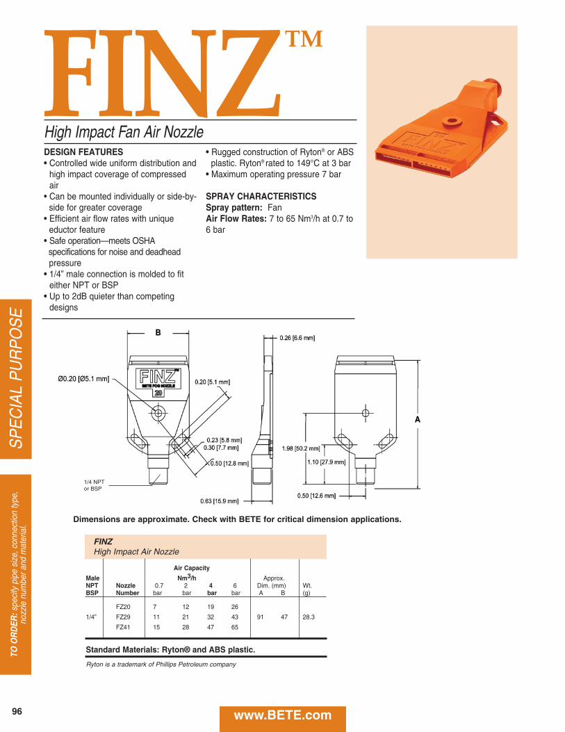
SP
EC
IAL
PU
RP
OS
ETO
OR
DER
:spe
cify
pip
e si
ze, c
onne
ctio
n ty
pe,
nozz
le n
umbe
r and
mat
eria
l.
FINZTM
High Impact Fan Air Nozzle• Rugged construction of Ryton® or ABS
plastic. Ryton® rated to 149°C at 3 bar• Maximum operating pressure 7 bar
SPRAY CHARACTERISTICSSpray pattern: FanAir Flow Rates: 7 to 65 Nm3/h at 0.7 to6 bar
DESIGN FEATURES• Controlled wide uniform distribution and
high impact coverage of compressedair
• Can be mounted individually or side-by- side for greater coverage
• Efficient air flow rates with unique eductor feature
• Safe operation—meets OSHA specifications for noise and deadheadpressure
• 1/4” male connection is molded to fiteither NPT or BSP
• Up to 2dB quieter than competingdesigns
FINZHigh Impact Air Nozzle
Air Capacity
Male Nm3/h Approx.NPT Nozzle 0.7 2 4 6 Dim. (mm) Wt.BSP Number bar bar bar bar A B (g)
FZ20 7 12 19 26
1/4” FZ29 11 21 32 43 91 47 28.3
FZ41 15 28 47 65
Standard Materials: Ryton® and ABS plastic.
Ryton is a trademark of Phillips Petroleum company
1/4 NPTor BSP
Dimensions are approximate. Check with BETE for critical dimension applications.
www.BETE.com96
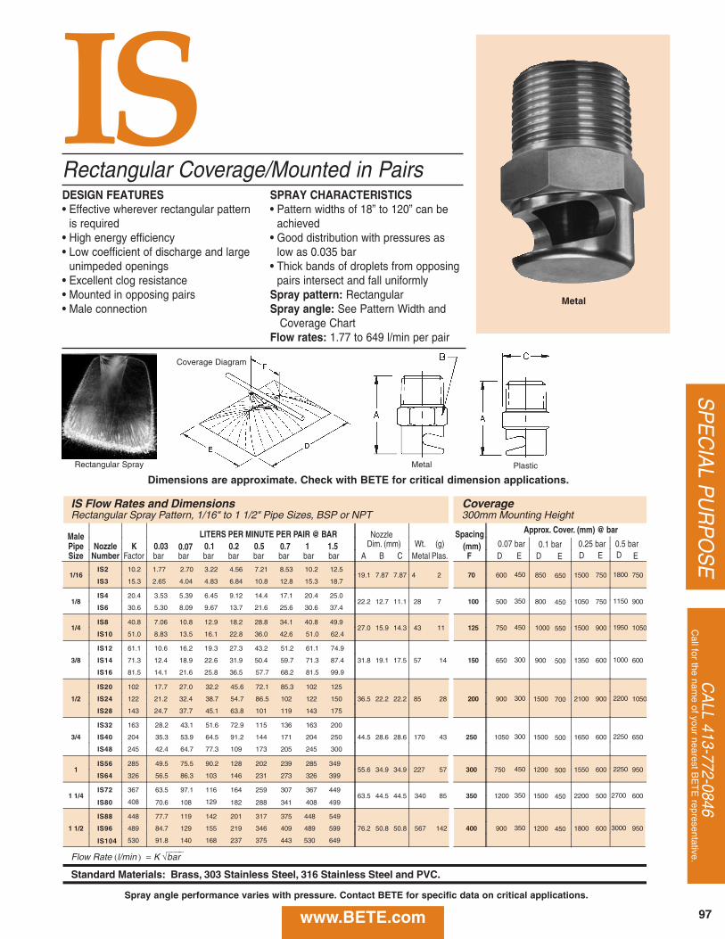
CA
LL 413-772-0846C
all for the name of your nearest B
ET
E representative.
SP
EC
IAL P
UR
PO
SE
ISRectangular Coverage/Mounted in PairsDESIGN FEATURES• Effective wherever rectangular pattern
is required• High energy efficiency• Low coefficient of discharge and large
unimpeded openings• Excellent clog resistance• Mounted in opposing pairs• Male connection
SPRAY CHARACTERISTICS• Pattern widths of 18” to 120” can be
achieved• Good distribution with pressures as
low as 0.035 bar• Thick bands of droplets from opposing
pairs intersect and fall uniformlySpray pattern: RectangularSpray angle: See Pattern Width and
Coverage ChartFlow rates: 1.77 to 649 l/min per pair
Rectangular Spray
Coverage Diagram
Metal Plastic
Metal
IS Flow Rates and Dimensions CoverageRectangular Spray Pattern, 1/16" to 1 1/2" Pipe Sizes, BSP or NPT 300mm Mounting Height
Male LITERS PER MINUTE PER PAIR @ BAR Spacing Approx. Cover. (mm) @ bar
Pipe Nozzle K 0.03 0.07 0.1 0.2 0.5 0.7 1 1.5 Dim. (mm) Wt. (g) (mm) 0.07 bar 0.1 bar 0.25 bar 0.5 barSize Number Factor bar bar bar bar bar bar bar bar A B C Metal Plas. F D E D E D E D E
1/16IS2 10.2 1.77 2.70 3.22 4.56 7.21 8.53 10.2 12.5
19.1 7.87 7.87 4 2 70 600 450 850 650 1500 750 1800 750IS3 15.3 2.65 4.04 4.83 6.84 10.8 12.8 15.3 18.7
1/8IS4 20.4 3.53 5.39 6.45 9.12 14.4 17.1 20.4 25.0
22.2 12.7 11.1 28 7 100 500 350 800 450 1050 750 1150 900IS6 30.6 5.30 8.09 9.67 13.7 21.6 25.6 30.6 37.4
1/4IS8 40.8 7.06 10.8 12.9 18.2 28.8 34.1 40.8 49.9
27.0 15.9 14.3 43 11 125 750 450 1000 550 1500 900 1950 1050IS10 51.0 8.83 13.5 16.1 22.8 36.0 42.6 51.0 62.4
3/8
IS12 61.1 10.6 16.2 19.3 27.3 43.2 51.2 61.1 74.9
31.8 19.1 17.5 57 14 150 650 300 900 500 1350 600 1000 600IS14 71.3 12.4 18.9 22.6 31.9 50.4 59.7 71.3 87.4
IS16 81.5 14.1 21.6 25.8 36.5 57.7 68.2 81.5 99.9
1/2
IS20 102 17.7 27.0 32.2 45.6 72.1 85.3 102 125
36.5 22.2 22.2 85 28 200 900 300 1500 700 2100 900 2200 1050IS24 122 21.2 32.4 38.7 54.7 86.5 102 122 150
IS28 143 24.7 37.7 45.1 63.8 101 119 143 175
3/4
IS32 163 28.2 43.1 51.6 72.9 115 136 163 200
44.5 28.6 28.6 170 43 250 1050 300 1500 500 1650 600 2250 650IS40 204 35.3 53.9 64.5 91.2 144 171 204 250
IS48 245 42.4 64.7 77.3 109 173 205 245 300
1IS56 285 49.5 75.5 90.2 128 202 239 285 349
55.6 34.9 34.9 227 57 300 750 450 1200 500 1550 600 2250 950IS64 326 56.5 86.3 103 146 231 273 326 399
1 1/4IS72 367 63.5 97.1 116 164 259 307 367 449
63.5 44.5 44.5 340 85 350 1200 350 1500 450 2200 500 2700 600IS80 408 70.6 108 129 182 288 341 408 499
1 1/2
IS88 448 77.7 119 142 201 317 375 448 549
76.2 50.8 50.8 567 142 400 900 350 1200 450 1800 600 3000 950IS96 489 84.7 129 155 219 346 409 489 599
IS104 530 91.8 140 168 237 375 443 530 649
Flow Rate (l/min ) = K √⎯⎯⎯⎯bar
Standard Materials: Brass, 303 Stainless Steel, 316 Stainless Steel and PVC.
Nozzle
Dimensions are approximate. Check with BETE for critical dimension applications.
www.BETE.com 97
Spray angle performance varies with pressure. Contact BETE for specific data on critical applications.
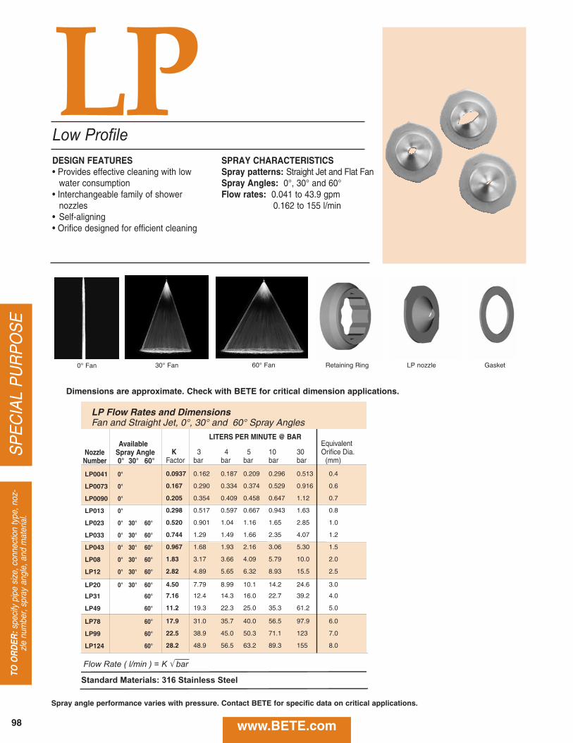
SP
EC
IAL
PU
RP
OS
ETO
OR
DER
:spe
cify
pip
e si
ze, c
onne
ctio
n ty
pe, n
oz-
zle
num
ber,
spra
y an
gle,
and
mat
eria
l.
30° Fan
Low ProfileLPDESIGN FEATURES• Provides effective cleaning with low
water consumption• Interchangeable family of shower
nozzles• Self-aligning• Orifice designed for efficient cleaning
SPRAY CHARACTERISTICSSpray patterns: Straight Jet and Flat FanSpray Angles: 0°, 30° and 60°Flow rates: 0.041 to 43.9 gpm
0.162 to 155 l/min
Retaining Ring LP nozzle Gasket
LITERS PER MINUTE @ BARAvailable Equivalent
Nozzle Spray Angle K 3 4 5 10 30 Orifice Dia. Number 0° 30° 60° Factor bar bar bar bar bar (mm)
LP0041 0° 0.0937 0.162 0.187 0.209 0.296 0.513 0.4
LP0073 0° 0.167 0.290 0.334 0.374 0.529 0.916 0.6
LP0090 0° 0.205 0.354 0.409 0.458 0.647 1.12 0.7
LP013 0° 0.298 0.517 0.597 0.667 0.943 1.63 0.8
LP023 0° 30° 60° 0.520 0.901 1.04 1.16 1.65 2.85 1.0
LP033 0° 30° 60° 0.744 1.29 1.49 1.66 2.35 4.07 1.2
LP043 0° 30° 60° 0.967 1.68 1.93 2.16 3.06 5.30 1.5
LP08 0° 30° 60° 1.83 3.17 3.66 4.09 5.79 10.0 2.0
LP12 0° 30° 60° 2.82 4.89 5.65 6.32 8.93 15.5 2.5
LP20 0° 30° 60° 4.50 7.79 8.99 10.1 14.2 24.6 3.0
LP31 60° 7.16 12.4 14.3 16.0 22.7 39.2 4.0
LP49 60° 11.2 19.3 22.3 25.0 35.3 61.2 5.0
LP78 60° 17.9 31.0 35.7 40.0 56.5 97.9 6.0
LP99 60° 22.5 38.9 45.0 50.3 71.1 123 7.0
LP124 60° 28.2 48.9 56.5 63.2 89.3 155 8.0
Flow Rate ( l/min ) = K √ bar
Standard Materials: 316 Stainless Steel
LP Flow Rates and DimensionsFan and Straight Jet, 0°, 30° and 60° Spray Angles
60° Fan0° Fan
Dimensions are approximate. Check with BETE for critical dimension applications.
www.BETE.com98
Spray angle performance varies with pressure. Contact BETE for specific data on critical applications.
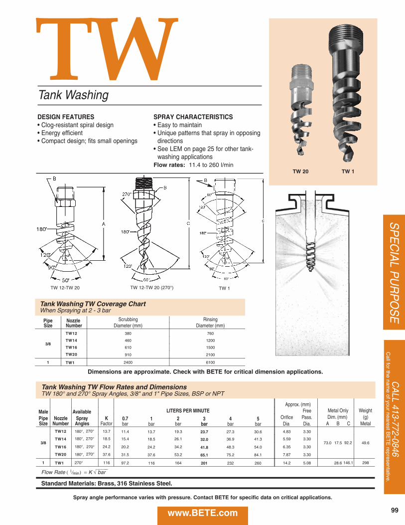
CA
LL 413-772-0846C
all for the name of your nearest B
ET
E representative.
SP
EC
IAL P
UR
PO
SE
www.BETE.com 99
TWTank Washing
DESIGN FEATURES• Clog-resistant spiral design• Energy efficient• Compact design; fits small openings
SPRAY CHARACTERISTICS• Easy to maintain• Unique patterns that spray in opposing
directions• See LEM on page 25 for other tank-
washing applicationsFlow rates: 11.4 to 260 l/min
TW 1TW 12-TW 20
TW 20 TW 1
Tank Washing TW Flow Rates and DimensionsTW 180° and 270° Spray Angles, 3/8" and 1" Pipe Sizes, BSP or NPT
Approx. (mm)Male Available LITERS PER MINUTE Metal Only Weight
Pipe Nozzle Spray K 0.7 1 2 3 4 5 Dim. (mm) (g)Size Number Angles Factor bar bar bar bar bar bar A B C Metal
3/8
TW12 180°, 13.7 11.4 13.7 19.3 23.7 27.3 30.6
73.0 17.5 49.6TW14 180°, 18.5 15.4 18.5 26.1 32.0 36.9 41.3
TW16 180°, 24.2 20.2 24.2 34.2 41.8 48.3 54.0
TW20 180°, 37.6 31.5 37.6 53.2 65.1 75.2 84.1
1 TW1 270° 116 97.2 116 164 201 232 260
FreeOrifice Pass.Dia Dia.4.83 3.30
5.59 3.30
6.35 3.30
7.87 3.30
14.2 5.08 146.1 298
Flow Rate ( l ⁄min ) = K √⎯⎯⎯⎯⎯ bar
Standard Materials: Brass, 316 Stainless Steel.
270°
270°
270°
270°
92.2
28.6
Pipe Nozzle Scrubbing Rinsing Size Number Diameter (mm) Diameter (mm)
3/8
TW12 380 760
TW14 460 1200
TW16 610 1500
TW20 910 2100
1 TW1 2400 6100
Dimensions are approximate. Check with BETE for critical dimension applications.
Spray angle performance varies with pressure. Contact BETE for specific data on critical applications.
TW 12-TW 20 (270°)
60°
B
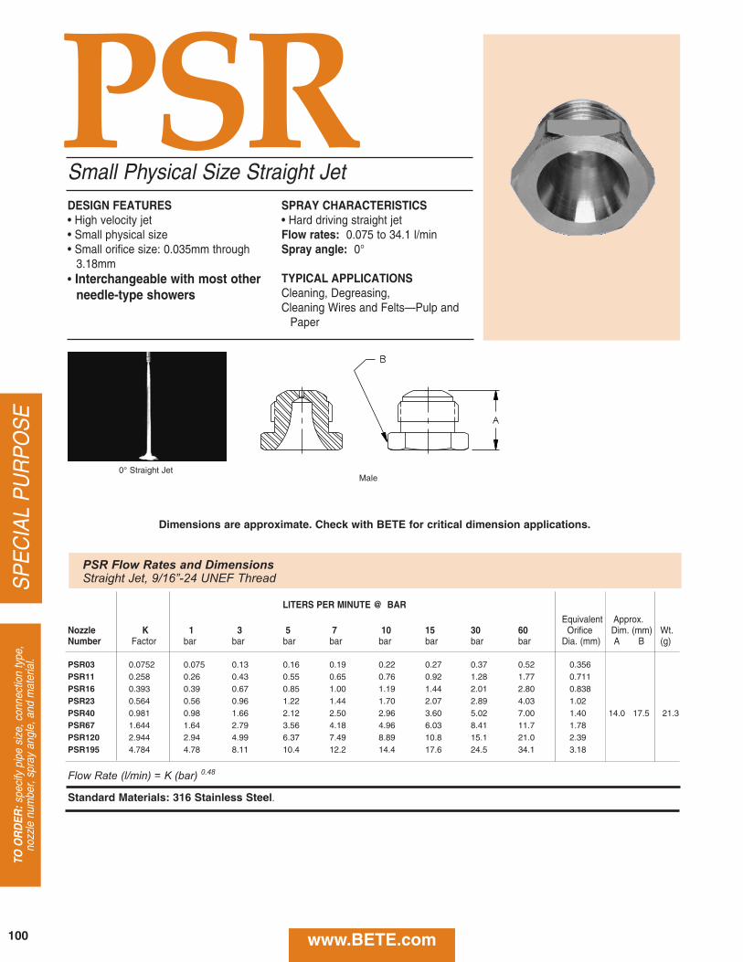
SP
EC
IAL
PU
RP
OS
E
www.BETE.com
TO O
RD
ER:s
peci
fy p
ipe
size
, con
nect
ion
type
, no
zzle
num
ber,
spra
y an
gle,
and
mat
eria
l.
DESIGN FEATURES• High velocity jet• Small physical size• Small orifice size: 0.035mm through
3.18mm• Interchangeable with most other
needle-type showers
SPRAY CHARACTERISTICS• Hard driving straight jetFlow rates: 0.075 to 34.1 l/minSpray angle: 0°
TYPICAL APPLICATIONSCleaning, Degreasing,Cleaning Wires and Felts—Pulp and
Paper
Small Physical Size Straight Jet
0° Straight JetMale
PSR
LITERS PER MINUTE @ BAR
Equivalent Approx.Nozzle K 1 3 5 7 10 15 30 60 Orifice Dim. (mm) Wt.Number Factor bar bar bar bar bar bar bar bar Dia. (mm) A B (g)
PSR03 0.0752 0.075 0.13 0.16 0.19 0.22 0.27 0.37 0.52 0.356PSR11 0.258 0.26 0.43 0.55 0.65 0.76 0.92 1.28 1.77 0.711PSR16 0.393 0.39 0.67 0.85 1.00 1.19 1.44 2.01 2.80 0.838PSR23 0.564 0.56 0.96 1.22 1.44 1.70 2.07 2.89 4.03 1.02PSR40 0.981 0.98 1.66 2.12 2.50 2.96 3.60 5.02 7.00 1.40 14.0 17.5 21.3PSR67 1.644 1.64 2.79 3.56 4.18 4.96 6.03 8.41 11.7 1.78PSR120 2.944 2.94 4.99 6.37 7.49 8.89 10.8 15.1 21.0 2.39PSR195 4.784 4.78 8.11 10.4 12.2 14.4 17.6 24.5 34.1 3.18
Flow Rate (l/min) = K (bar) 0.48
Standard Materials: 316 Stainless Steel.
PSR Flow Rates and DimensionsStraight Jet, 9/16”-24 UNEF Thread
Dimensions are approximate. Check with BETE for critical dimension applications.
100
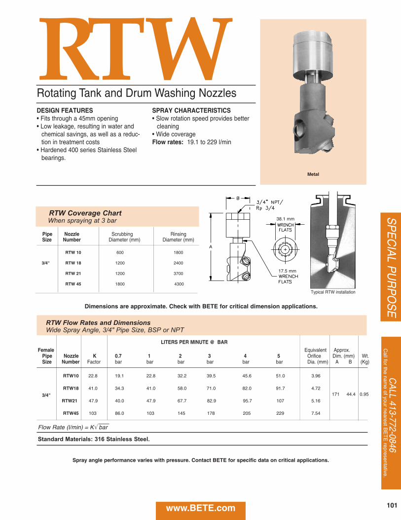
DESIGN FEATURES• Fits through a 45mm opening • Low leakage, resulting in water and
chemical savings, as well as a reduc-tion in treatment costs
• Hardened 400 series Stainless Steelbearings.
SPRAY CHARACTERISTICS• Slow rotation speed provides better
cleaning• Wide coverageFlow rates: 19.1 to 229 l/min
RTWRotating Tank and Drum Washing Nozzles
Typical RTW installation
Metal
LITERS PER MINUTE @ BAR
Female Equivalent Approx.Pipe Nozzle K 0.7 1 2 3 4 5 Orifice Dim. (mm) Wt.Size Number Factor bar bar bar bar bar bar Dia. (mm) A B (Kg)
RTW10 22.8 19.1 22.8 32.2 39.5 45.6 51.0 3.96
RTW18 41.0 34.3 41.0 58.0 71.0 82.0 91.7 4.72 171 44.4 0.953/4"
RTW21 47.9 40.0 47.9 67.7 82.9 95.7 107 5.16
RTW45 103 86.0 103 145 178 205 229 7.54
Flow Rate (l/min) = K√ bar
Standard Materials: 316 Stainless Steel.
RTW Coverage ChartWhen spraying at 3 bar
Pipe Nozzle Scrubbing RinsingSize Number Diameter (mm) Diameter (mm)
RTW 10 600 1800
3/4" RTW 18 1200 2400
RTW 21 1200 3700
RTW 45 1800 4300
RTW Flow Rates and DimensionsWide Spray Angle, 3/4" Pipe Size, BSP or NPT
CA
LL 413-772-0846C
all for the name of your nearest B
ET
E representative.
SP
EC
IAL P
UR
PO
SEDimensions are approximate. Check with BETE for critical dimension applications.
www.BETE.com 101
38.1 mm
17.5 mm
Spray angle performance varies with pressure. Contact BETE for specific data on critical applications.
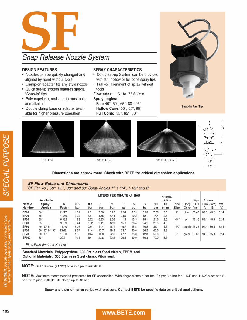
DESIGN FEATURES• Nozzles can be quickly changed and
aligned by hand without tools• Clamp-on adapter fits any style nozzle• Quick set-up system features special
“Snap-in” tips• Polypropylene, resistant to most acids
and alkalies• Double clamp base or adapter avail-
able for higher pressure operation
SPRAY CHARACTERISTICS• Quick Set-up System can be provided
with fan, hollow or full cone spray tips• Full 45° alignment of spray without
toolsFlow rates: 1.61 to 75.6 l/minSpray angles:
Fan: 40°, 50°, 65°, 80°, 95°Hollow Cone: 50°, 65°, 90°Full Cone: 35°, 65°, 80°
Snap Release Nozzle System
50° Fan 80° Full Cone 90° Hollow Cone
SF
A
B
2.1”45°
LITERS PER MINUTE @ BAR Approx.Available Orifice Pipe Approx.
Nozzle Spray K 0.5 0.7 1 2 3 5 7 10 Dia. Pipe Body O.D. Dim. (mm) Wt.Number Angles Factor bar bar bar bar bar bar bar bar (mm) Size Color (mm) A B (g)SF10 80° 2.277 1.61 1.91 2.28 3.22 3.94 5.09 6.03 7.20 2.0 1” blue 33.40 83.8 43.2 62.4SF20 65° 4.556 3.22 3.81 4.55 6.44 7.89 10.2 12.1 14.4 2.8SF30 65° 6.832 4.83 5.72 6.83 9.66 11.8 15.3 18.1 21.6 3.6 1-1/4” red 42.16 86.4 48.3 62.4SF40 65° 9.109 6.44 7.62 9.11 12.9 15.8 20.4 24.1 28.8 4.0SF50 40° 50° 65° 11.40 8.06 9.54 11.4 16.1 19.7 25.5 30.2 36.1 4.4 1-1/2” purple 48.26 91.4 50.8 62.4SF60 50° 65° 80° 95° 13.68 9.67 11.4 13.7 19.3 23.7 30.6 36.2 43.3 4.8SF70 50° 80° 16.00 11.3 13.4 16.0 22.6 27.7 35.8 42.3 50.6 5.2 2” green 60.33 94.0 55.9 62.4SF100 50° 22.7 16.1 19.1 22.8 32.2 39.4 50.9 60.3 72.0 6.4
Flow Rate (l/min) = K √ bar
Standard Materials: Polypropylene, 302 Stainless Steel clamp, EPDM seal.Optional Materials: 303 Stainless Steel clamp, Viton seal.
SF Flow Rates and DimensionsSF Fan 40°, 50°, 65°, 80° and 90° Spray Angles 1”, 1-1/4”, 1-1/2” and 2”
NOTE: Drill 16.7mm (21/32”) hole in pipe to install SF.
NOTE: Maximum recommended pressures for SF assemblies: With single clamp 5 bar for 1” pipe; 3.5 bar for 1-1/4” and 1-1/2” pipe; and 2bar for 2” pipe; with double clamp up to 10 bar.
SP
EC
IAL
PU
RP
OS
ETO
OR
DER
:spe
cify
pip
e si
ze, c
onne
ctio
n ty
pe,
nozz
le n
umbe
r, sp
ray
angl
e, a
nd m
ater
ial.
Snap-In Fan Tip
Dimensions are approximate. Check with BETE for critical dimension applications.
www.BETE.com102
Spray angle performance varies with pressure. Contact BETE for specific data on critical applications.
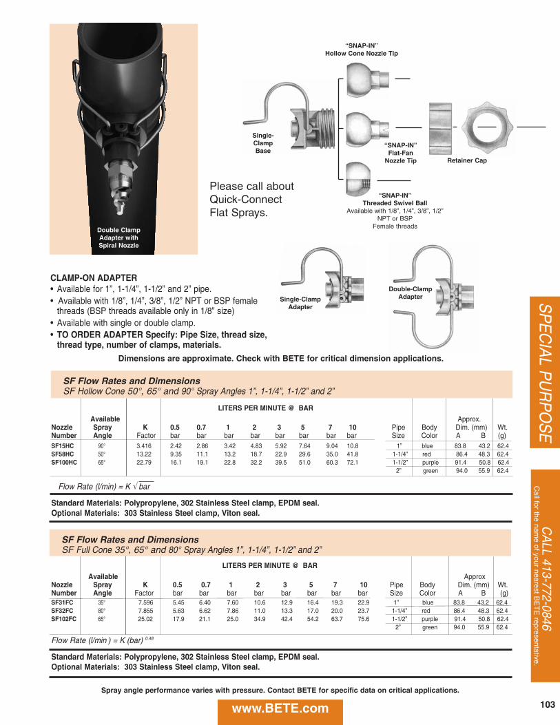
CA
LL 413-772-0846C
all for the name of your nearest B
ET
E representative.
SP
EC
IAL P
UR
PO
SE
CLAMP-ON ADAPTER• Available for 1”, 1-1/4”, 1-1/2” and 2” pipe.• Available with 1/8”, 1/4”, 3/8”, 1/2” NPT or BSP female
threads (BSP threads available only in 1/8” size)• Available with single or double clamp.• TO ORDER ADAPTER Specify: Pipe Size, thread size,
thread type, number of clamps, materials.
Double-Clamp Adapter
Single-Clamp Base
Retainer Cap
“SNAP-IN”Flat-Fan
Nozzle Tip
“SNAP-IN”Hollow Cone Nozzle Tip
“SNAP-IN”Threaded Swivel Ball
Available with 1/8”, 1/4”, 3/8”, 1/2”NPT or BSP
Female threads
Single-Clamp Adapter
LITERS PER MINUTE @ BAR
Available Approx.Nozzle Spray K 0.5 0.7 1 2 3 5 7 10 Pipe Body Dim. (mm) Wt.Number Angle Factor bar bar bar bar bar bar bar bar Size Color A B (g)SF15HC 90° 3.416 2.42 2.86 3.42 4.83 5.92 7.64 9.04 10.8 1” blue 83.8 43.2 62.4SF58HC 50° 13.22 9.35 11.1 13.2 18.7 22.9 29.6 35.0 41.8 1-1/4” red 86.4 48.3 62.4SF100HC 65° 22.79 16.1 19.1 22.8 32.2 39.5 51.0 60.3 72.1 1-1/2” purple 91.4 50.8 62.4
2” green 94.0 55.9 62.4
Flow Rate (l/min) = K √ bar
Standard Materials: Polypropylene, 302 Stainless Steel clamp, EPDM seal.Optional Materials: 303 Stainless Steel clamp, Viton seal.
LITERS PER MINUTE @ BAR
Available ApproxNozzle Spray K 0.5 0.7 1 2 3 5 7 10 Pipe Body Dim. (mm) Wt.Number Angle Factor bar bar bar bar bar bar bar bar Size Color A B (g)SF31FC 35° 7.596 5.45 6.40 7.60 10.6 12.9 16.4 19.3 22.9 1” blue 83.8 43.2 62.4SF32FC 80° 7.855 5.63 6.62 7.86 11.0 13.3 17.0 20.0 23.7 1-1/4” red 86.4 48.3 62.4SF102FC 65° 25.02 17.9 21.1 25.0 34.9 42.4 54.2 63.7 75.6 1-1/2” purple 91.4 50.8 62.4
2” green 94.0 55.9 62.4
Flow Rate (l/min ) = K (bar) 0.48
Standard Materials: Polypropylene, 302 Stainless Steel clamp, EPDM seal.Optional Materials: 303 Stainless Steel clamp, Viton seal.
SF Flow Rates and DimensionsSF Hollow Cone 50°, 65° and 90° Spray Angles 1”, 1-1/4”, 1-1/2” and 2”
SF Flow Rates and DimensionsSF Full Cone 35°, 65° and 80° Spray Angles 1”, 1-1/4”, 1-1/2” and 2”
Double Clamp Adapter with Spiral Nozzle
Please call aboutQuick-Connect Flat Sprays.
Dimensions are approximate. Check with BETE for critical dimension applications.
www.BETE.com 103
Spray angle performance varies with pressure. Contact BETE for specific data on critical applications.
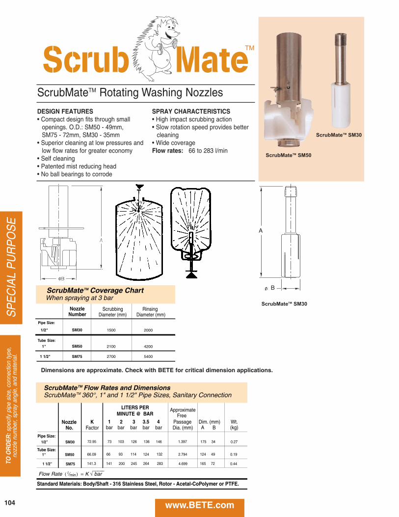
SP
EC
IAL
PU
RP
OS
ETO
OR
DER
:spe
cify
pip
e si
ze, c
onne
ctio
n ty
pe,
nozz
le n
umbe
r, sp
ray
angl
e, a
nd m
ater
ial.
DESIGN FEATURES• Compact design fits through small
openings. O.D.: SM50 - 49mm, SM75 - 72mm, SM30 - 35mm
• Superior cleaning at low pressures andlow flow rates for greater economy
• Self cleaning• Patented mist reducing head• No ball bearings to corrode
SPRAY CHARACTERISTICS• High impact scrubbing action • Slow rotation speed provides better
cleaning• Wide coverageFlow rates: 66 to 283 l/min
ScrubMateTM Rotating Washing Nozzles
NozzleNo.
SM501“
SM751 1/2”
Flow Rate ( l ⁄min ) = K √⎯⎯⎯⎯⎯ bar
SM301/2”
Standard Materials: Body/Shaft - 316 Stainless Steel, Rotor - Acetal-CoPolymer or PTFE.
LITERS PER MINUTE @ BAR
ApproximateFree
K 1 2 3 Passage Dim. (mm) Wt.Factor bar bar bar Dia. (mm) A B (kg)
3.5bar
4bar
66.09 66 93 114 2.794 124 49 0.19
141.3 141 200 245 4.699
124
264
132
283 165 72 0.44
72.95 73 103 126 1.397 175 34 0.27136 146
Pipe Size:
Tube Size:
ScrubMateTM Flow Rates and DimensionsScrubMateTM 360°, 1" and 1 1/2" Pipe Sizes, Sanitary Connection
Pipe
Nozzle
Size:
Number
SM301/2"
Scrubbing RinsingDiameter (mm) Diameter (mm)
1500 2000
SM75 2700 54001 1/2"
ScrubMateTM Coverage ChartWhen spraying at 3 bar
SM501" 2100 4200
Tube Size:
TM
ScrubMateTM SM50
Dimensions are approximate. Check with BETE for critical dimension applications.
www.BETE.com
C
D
ScrubMateTM SM30
ScrubMateTM SM30
A
B
104
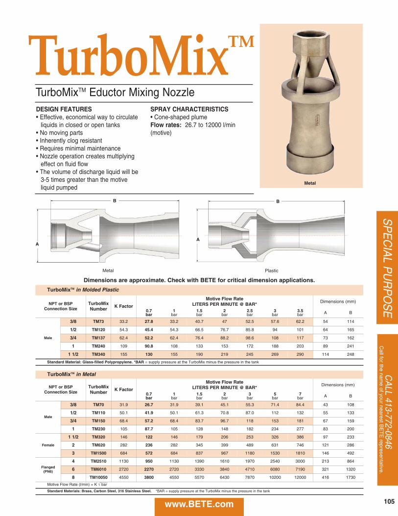
CA
LL 413-772-0846C
all for the name of your nearest B
ET
E representative.
SP
EC
IAL P
UR
PO
SE
www.BETE.com
DESIGN FEATURES• Effective, economical way to circulate
liquids in closed or open tanks• No moving parts• Inherently clog resistant• Requires minimal maintenance• Nozzle operation creates multiplying
effect on fluid flow• The volume of discharge liquid will be
3-5 times greater than the motiveliquid pumped
SPRAY CHARACTERISTICS• Cone-shaped plumeFlow rates: 26.7 to 12000 l/min (motive)
TurboMixTM
TurboMixTM Eductor Mixing Nozzle
Metal
Metal Plastic
TurboMixTM in Molded Plastic
NPT or BSP Connection Size
TurboMixNumber
K Factor
Motive Flow RateLITERS PER MINUTE @ BAR*
Dimensions (mm)
0.7bar
1bar
1.5bar
2bar
2.5bar
3bar
3.5bar A B
Male
3/8 TM73 33.2 27.8 33.2 40.7 47 52.5 57.6 62.2 54 114
1/2 TM120 54.3 45.4 54.3 66.5 76.7 85.8 94 101 64 165
3/4 TM137 62.4 52.2 62.4 76.4 88.2 98.6 108 117 73 162
1 TM240 109 90.8 108 133 153 172 188 203 89 241
1 1/2 TM340 155 130 155 190 219 245 269 290 114 248
Standard Material: Glass-filled Polypropylene. *BAR = supply pressure at the TurboMix minus the pressure in the tank
TurboMixTM in Metal
NPT or BSP Connection Size
TurboMixNumber
K Factor
Motive Flow RateLITERS PER MINUTE @ BAR*
Dimensions (mm)
0.7bar
1bar
1.5bar
2bar
3bar
5bar
7bar A B
Male
3/8 TM70 31.9 26.7 31.9 39.1 45.1 55.3 71.4 84.4 43 108
1/2 TM110 50.1 41.9 50.1 61.3 70.8 87.0 112 132 55 133
3/4 TM150 68.4 57.2 68.4 83.7 96.7 118 153 181 67 159
1 TM230 105 87.7 105 128 148 182 234 277 83 200
Female
1 1/2 TM320 146 122 146 179 206 253 326 386 97 233
2 TM620 282 236 282 345 399 489 631 746 121 286
3 TM1500 684 572 684 837 967 1180 1530 1810 146 492
Flanged(PN6)
4 TM2510 1130 950 1130 1390 1610 1970 2540 3000 213 864
6 TM6010 2720 2270 2720 3330 3840 4710 6080 7190 321 1320
8 TM10050 4550 3800 4550 5570 6430 7870 10200 12000 416 1730
Motive Flow Rate (l/min) = K √ bar
Standard Materials: Brass, Carbon Steel, 316 Stainless Steel. *BAR = supply pressure at the TurboMix minus the pressure in the tank
B
AA
B
Dimensions are approximate. Check with BETE for critical dimension applications.
105
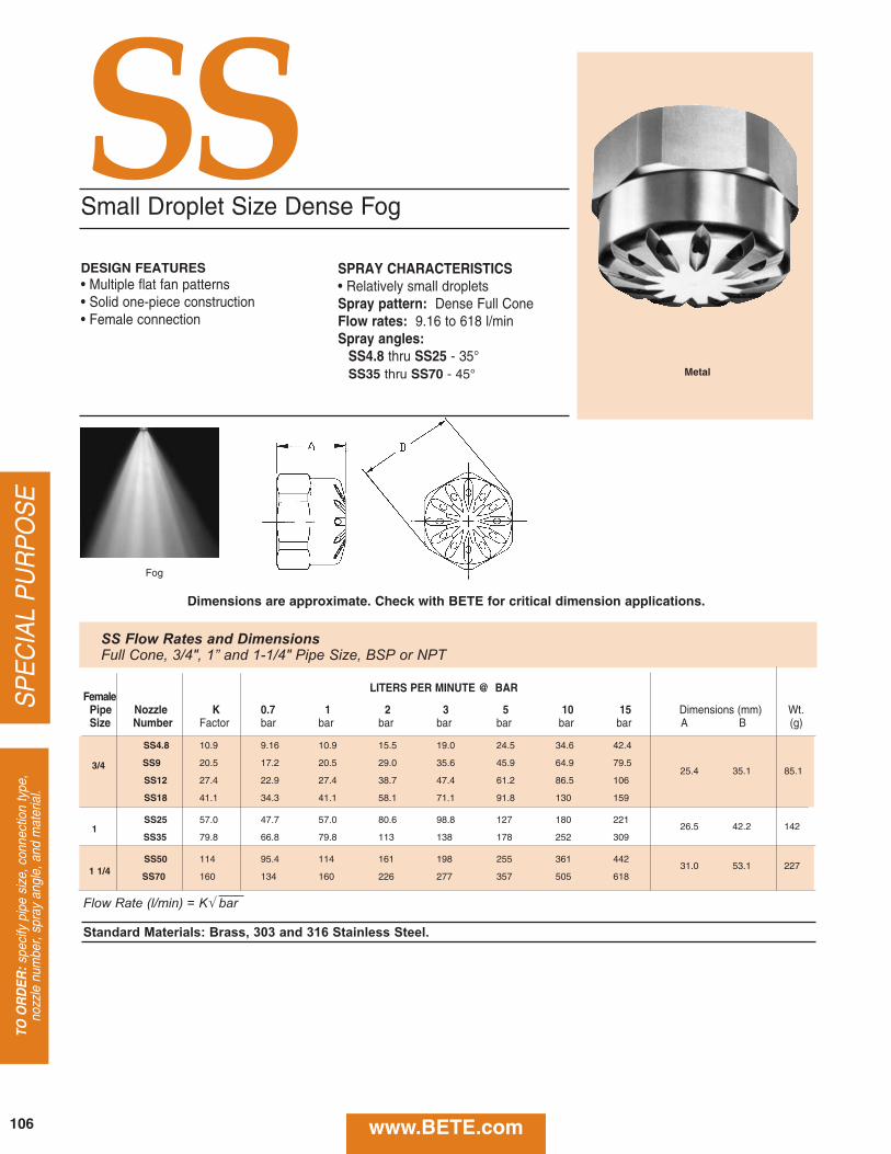
SP
EC
IAL
PU
RP
OS
ETO
OR
DER
:spe
cify
pip
e si
ze, c
onne
ctio
n ty
pe,
nozz
le n
umbe
r, sp
ray
angl
e, a
nd m
ater
ial.
SSSmall Droplet Size Dense Fog
DESIGN FEATURES• Multiple flat fan patterns• Solid one-piece construction• Female connection
SPRAY CHARACTERISTICS• Relatively small dropletsSpray pattern: Dense Full ConeFlow rates: 9.16 to 618 l/minSpray angles:
SS4.8 thru SS25 - 35°SS35 thru SS70 - 45°
Fog
Metal
LITERS PER MINUTE @ BARFemale
Pipe Nozzle K 0.7 1 2 3 5 10 15 Dimensions (mm) Wt.Size Number Factor bar bar bar bar bar bar bar A B (g)
SS4.8 10.9 9.16 10.9 15.5 19.0 24.5 34.6 42.4
3/4 SS9 20.5 17.2 20.5 29.0 35.6 45.9 64.9 79.525.4 35.1 85.1
SS12 27.4 22.9 27.4 38.7 47.4 61.2 86.5 106
SS18 41.1 34.3 41.1 58.1 71.1 91.8 130 159
SS25 57.0 47.7 57.0 80.6 98.8 127 180 22126.5 42.2 1421
SS35 79.8 66.8 79.8 113 138 178 252 309
SS50 114 95.4 114 161 198 255 361 44231.0 53.1 2271 1/4 SS70 160 134 160 226 277 357 505 618
Flow Rate (l/min) = K√ bar
Standard Materials: Brass, 303 and 316 Stainless Steel.
SS Flow Rates and DimensionsFull Cone, 3/4", 1” and 1-1/4" Pipe Size, BSP or NPT
Dimensions are approximate. Check with BETE for critical dimension applications.
www.BETE.com106
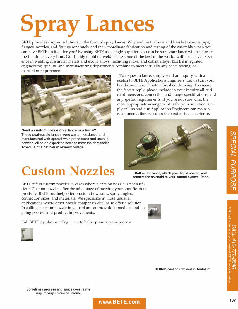
CA
LL 413-772-0846C
all for the name of your nearest B
ET
E representative.
SP
EC
IAL P
UR
PO
SE
www.BETE.com 107
BETE provides drop‑in solutions in the form of spray lances. Why endure the time and hassle to source pipe,flanges, nozzles, and fittings separately and then coordinate fabrication and testing of the assembly when youcan have BETE do it all for you? By using BETE as a single supplier, you can be sure your lance will be correctthe first time, every time. Our highly qualified welders are some of the best in the world, with extensive experi‑ence in welding dissimilar metals and exotic alloys, including nickel and cobalt alloys. BETE's integrated engineering, quality, and manufacturing departments combine to meet virtually any code, testing, or inspection requirement.
To request a lance, simply send an inquiry with asketch to BETE Applications Engineers. Let us turn yourhand‑drawn sketch into a finished drawing. To ensurethe fastest reply, please include in your inquiry all criti‑cal dimensions, connection and flange specifications, andany special requirements. If you're not sure what themost appropriate arrangement is for your situation, sim‑ply call us and our Application Engineers can make a recommendation based on their extensive experience.
Spray Lances
Need a custom nozzle on a lance in a hurry?These dual-nozzle lances were custom designed andmanufactured with special weld procedures and unusualnozzles, all on an expedited basis to meet the demandingschedule of a petroleum refinery outage.
Custom NozzlesBETE offers custom nozzles in cases where a catalog nozzle is not suffi‑cient. Custom nozzles offer the advantage of meeting your specificationsprecisely. BETE routinely offers custom flow rates, spray angles, connection sizes, and materials. We specialize in those unusual applications where other nozzle companies decline to offer a solution.Installing a custom nozzle in your plant can provide immediate and on‑going process and product improvements.
Call BETE Application Engineers to help optimize your process.
CLUMP, cast and welded in Tantalum
Bolt on the lance, attach your liquid source, and connect the solenoid to your control system. Done.
Sometimes process and space constraintsrequire very unique solutions.
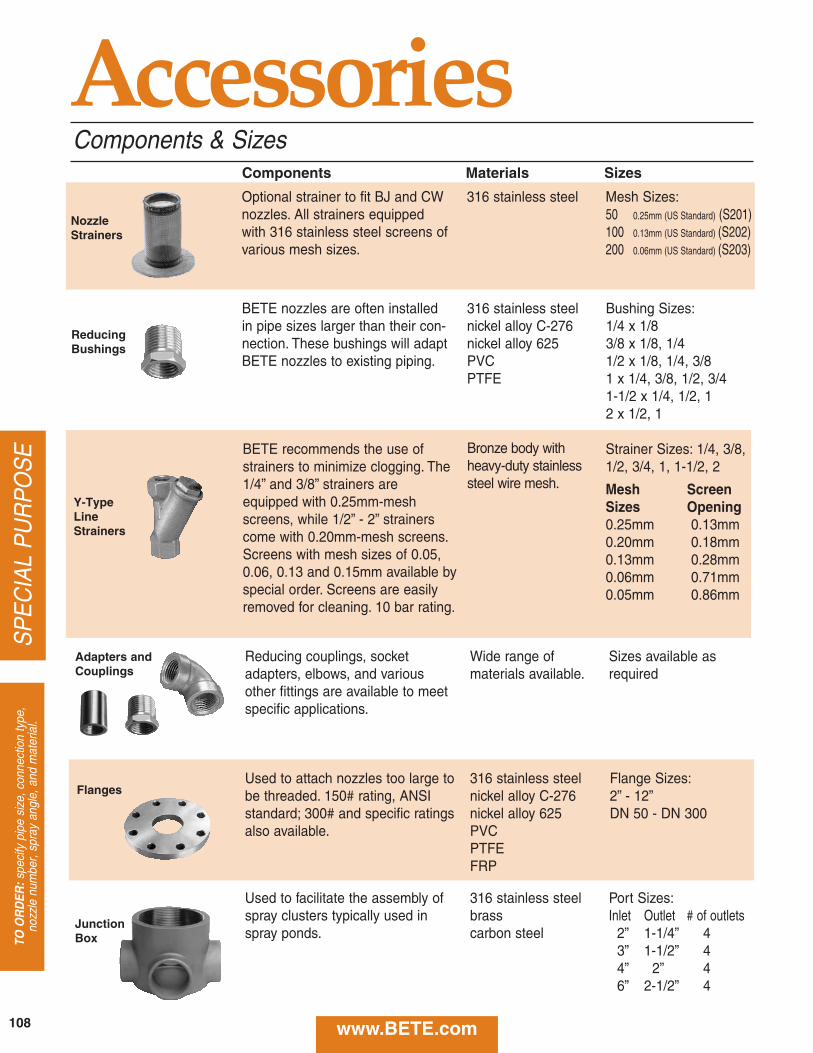
Adapters andCouplings
ReducingBushings
Used to facilitate the assembly ofspray clusters typically used inspray ponds.
Flange Sizes:2” - 12”DN 50 - DN 300
BETE recommends the use ofstrainers to minimize clogging. The1/4” and 3/8” strainers areequipped with 0.25mm-meshscreens, while 1/2” - 2” strainerscome with 0.20mm-mesh screens.Screens with mesh sizes of 0.05,0.06, 0.13 and 0.15mm available byspecial order. Screens are easilyremoved for cleaning. 10 bar rating.
Strainer Sizes: 1/4, 3/8,1/2, 3/4, 1, 1-1/2, 2
Mesh ScreenSizes Opening0.25mm 0.13mm0.20mm 0.18mm0.13mm 0.28mm0.06mm 0.71mm0.05mm 0.86mm
BETE nozzles are often installedin pipe sizes larger than their con-nection. These bushings will adaptBETE nozzles to existing piping.
316 stainless steelnickel alloy C-276nickel alloy 625PVCPTFE
316 stainless steelnickel alloy C-276nickel alloy 625PVCPTFEFRP
Bushing Sizes:1/4 x 1/83/8 x 1/8, 1/41/2 x 1/8, 1/4, 3/81 x 1/4, 3/8, 1/2, 3/41-1/2 x 1/4, 1/2, 12 x 1/2, 1
Reducing couplings, socketadapters, elbows, and variousother fittings are available to meetspecific applications.
Wide range of materials available.
Sizes available asrequired
Used to attach nozzles too large tobe threaded. 150# rating, ANSIstandard; 300# and specific ratingsalso available.
316 stainless steelbrasscarbon steel
Port Sizes:Inlet Outlet # of outlets
2” 1-1/4” 43” 1-1/2” 44” 2” 46” 2-1/2” 4
Components Materials Sizes
NozzleStrainers
Y-TypeLineStrainers
Flanges
JunctionBox
AccessoriesComponents & Sizes
Optional strainer to fit BJ and CWnozzles. All strainers equippedwith 316 stainless steel screens ofvarious mesh sizes.
316 stainless steel Mesh Sizes:50 0.25mm (US Standard) (S201)100 0.13mm (US Standard) (S202)200 0.06mm (US Standard) (S203)
Bronze body withheavy-duty stainlesssteel wire mesh.
108
SP
EC
IAL
PU
RP
OS
ETO
OR
DER
:spe
cify
pip
e si
ze, c
onne
ctio
n ty
pe,
nozz
le n
umbe
r, sp
ray
angl
e, a
nd m
ater
ial.
www.BETE.com
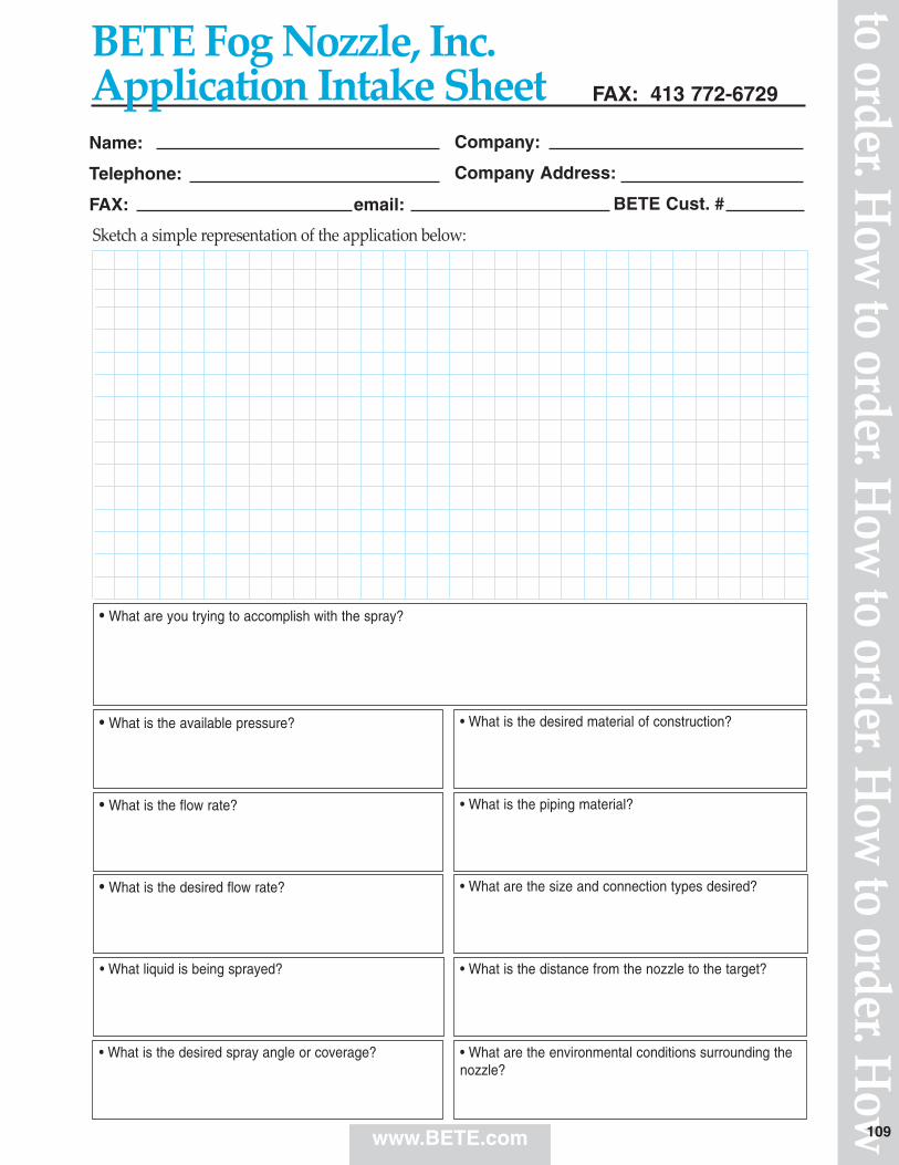
www.BETE.com
to order. How
to order. How
to order. How
to order. How
Sketch a simple representation of the application below:
Name:
Telephone:
FAX: email:
Company:
Company Address:
BETE Cust. #
• What is the piping material?
• What liquid is being sprayed?
• What are the environmental conditions surrounding thenozzle?
• What is the available pressure?
• What is the desired spray angle or coverage?
• What is the desired material of construction?
FAX: 413 772-6729
• What are you trying to accomplish with the spray?
• What is the desired flow rate?
• What is the flow rate?
• What are the size and connection types desired?
• What is the distance from the nozzle to the target?
BETE Fog Nozzle, Inc.Application Intake Sheet
109
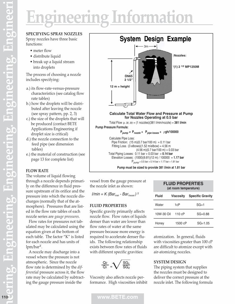
SPECIFYING SPRAY NOZZLESSpray nozzles have three basicfunctions:
The process of choosing a nozzleincludes specifying:
FLOW RATEThe volume of liquid flowingthrough a nozzle depends primari‑ly on the difference in fluid pres‑sure upstream of its orifice and thepressure into which the nozzle dis‑charges (normally that of the at‑mosphere). Pressures that are list‑ed in the flow rate tables of eachnozzle series are gauge pressures.
Flow rates for pressures not tab‑ulated may be calculated using theequation given at the bottom ofeach table. The factor “K” is listedfor each nozzle and has units oflpm/barx.
A nozzle may discharge into avessel where the pressure is notatmospheric. Since the nozzleflow rate is determined by the dif‑ferential pressure across it, the flowrate may be calculated by subtract‑ing the gauge pressure inside the
vessel from the gauge pressure atthe nozzle inlet as shown:
FLUID PROPERTIESSpecific gravity primarily affectsnozzle flow. Flow rates of liquidsdenser than water are lower thanflow rates of water at the samepressure because more energy isrequired to accelerate denser flu‑ids. The following relationshipexists between flow rates of fluidswith different specific gravities:
Viscosity also affects nozzle per‑formance. High viscosities inhibit
atomization. In general, fluidswith viscosities greater than 100 cPare difficult to atomize except withair‑atomizing nozzles.
SYSTEM DESIGNThe piping system that suppliesthe nozzles must be designed to deliver the correct pressure at thenozzle inlet. The following formula
Engineering Information
Fluid Viscosity Specific Gravity
Water 1cP SG=1
10W-30 Oil 110 cP SG=0.88
Honey 1500 cP SG=1.05
FLUID PROPERTIES(at room temperature)
• meter flow• distribute liquid• break up a liquid stream
into droplets
a.) its flow‑rate‑versus‑pressurecharacteristics (see catalog flowrate tables)
b.) how the droplets will be distri‑buted after leaving the nozzle(see spray pattern, pp. 2, 3)
c.) the size of the droplets that willbe produced (contact BETEApplications Engineering ifdroplet size is critical)
d.) the nozzle connection to thefeed pipe (see dimensiontables)
e.) the material of construction (seepage 13 for complete list)
l/min = K (BarInlet - BarVessel ) x
Calculate Total Water Flow and Pressure at Pump for Nozzles Operating at 0.5 bar
Total Flow (p. 38, 39) = (1 nozzles)(381 l/min/nozzle) = 381 l/minPump Pressure Formula:
Ppump = Pnozzle + Ppipe losses + ρgh/100000
Calculate Pipe Loss:Pipe Friction: (15 m)(0.7 bar/100 m) = 0.11 barFitting Loss: (3 elbows)(1.52 m/elbow) = 4.56 m
(4.56 m)(0.7 bar/100 m) = 0.03 barTotal Piping Losses: 0.11 bar + 0.03 bar = 0.14 bar
Elevation Losses: (1000)(9.81)(12 m) / 100000 = 1.17 barPpump = 0.5 bar + 0.14 bar + 1.17 bar = 1.81 bar
Pump must be sized to provide 381 l/min at 1.81 bar
3m
Nozzles:
(1) 2 1/2 MP1250M
DN652 1/2”
12 m = height
www.BETE.comneer
ing.
Eng
inee
ring.
Eng
inee
ring.
Eng
inee
ring.
Eng
inee
ri
110
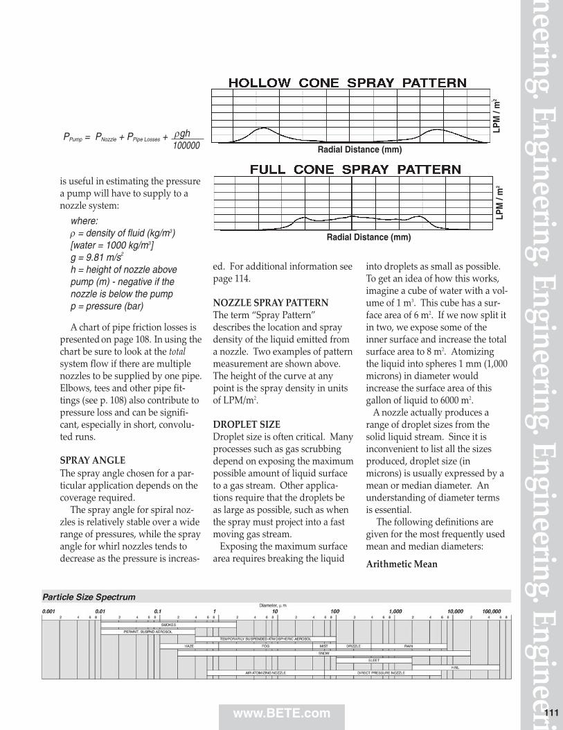
is useful in estimating the pressurea pump will have to supply to anozzle system:
where:ρ = density of fluid (kg/m3)[water = 1000 kg/m3]g = 9.81 m/s2
h = height of nozzle abovepump (m) - negative if thenozzle is below the pumpp = pressure (bar)
A chart of pipe friction losses ispresented on page 108. In using the chart be sure to look at the totalsystem flow if there are multiplenozzles to be supplied by one pipe.Elbows, tees and other pipe fit‑tings (see p. 108) also contribute topressure loss and can be signifi‑cant, especially in short, convolu‑ted runs.
SPRAY ANGLEThe spray angle chosen for a par‑ticular application depends on thecoverage required.
The spray angle for spiral noz‑zles is relatively stable over a widerange of pressures, while the sprayangle for whirl nozzles tends todecrease as the pressure is increas‑
ed. For additional information seepage 114.
NOZZLE SPRAY PATTERNThe term “Spray Pattern”describes the location and spraydensity of the liquid emitted froma nozzle. Two examples of patternmeasurement are shown above.The height of the curve at anypoint is the spray density in unitsof LPM/m2.
DROPLET SIZEDroplet size is often critical. Manyprocesses such as gas scrubbingdepend on exposing the maximumpossible amount of liquid surfaceto a gas stream. Other applica‑tions require that the droplets beas large as possible, such as whenthe spray must project into a fastmoving gas stream.
Exposing the maximum surfacearea requires breaking the liquid
into droplets as small as possible.To get an idea of how this works,imagine a cube of water with a vol‑ume of 1 m3. This cube has a sur‑face area of 6 m2. If we now split itin two, we expose some of theinner surface and increase the totalsurface area to 8 m2. Atomizingthe liquid into spheres 1 mm (1,000microns) in diameter wouldincrease the surface area of thisgallon of liquid to 6000 m2.
A nozzle actually produces arange of droplet sizes from thesolid liquid stream. Since it isinconvenient to list all the sizesproduced, droplet size (inmicrons) is usually expressed by amean or median diameter. Anunderstanding of diameter termsis essential.
The following definitions aregiven for the most frequently usedmean and median diameters:
Arithmetic Mean
PPump = PNozzle + PPipe Losses + ρgh100000 Radial Distance (mm)
LPM
/ m
2LP
M /
m2
Radial Distance (mm)
neering. Engineering. Engineering. Engineering. Engineeriwww.BETE.com 111
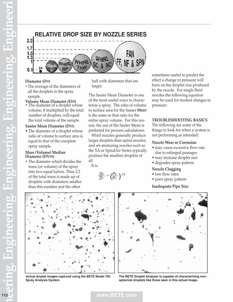
Diameter (D10)• The average of the diameters of
all the droplets in the spray sample.
Volume Mean Diameter (D30)• The diameter of a droplet whose
volume, if multiplied by the totalnumber of droplets, will equalthe total volume of the sample.
Sauter Mean Diameter (D32): • The diameter of a droplet whose
ratio of volume to surface area isequal to that of the completespray sample.
Mass (Volume) MedianDiameter (DV05):• The diameter which divides the
mass (or volume) of the sprayinto two equal halves. Thus 1/2of the total mass is made up ofdroplets with diameters smallerthan this number and the other
half with diameters that arelarger.
The Sauter Mean Diameter is oneof the most useful ways to charac‑terize a spray. The ratio of volumeto surface area for the Sauter Meanis the same as that ratio for theentire spray volume. For this rea‑son, the use of the Sauter Mean ispreferred for process calculations.
Whirl nozzles generally producelarger droplets than spiral nozzles,and air‑atomizing nozzles such asthe XA or SpiralAir Series typicallyproduce the smallest droplets ofall.
It is
sometimes useful to predict theeffect a change in pressure willhave on the droplet size producedby the nozzle. For single fluidnozzles the following equationmay be used for modest changes inpressure:
TROUBLESHOOTING BASICSThe following are some of thethings to look for when a system is not performing as intended:
Nozzle Wear or Corrosion• may cause excessive flow rate
due to enlarged passages• may increase droplet size• degrades spray patternNozzle Clogging• low flow rates• poor spray pattern
Inadequate Pipe Size
D2D1
P2P1( )-0.3=
neer
ing.
Eng
inee
ring.
Eng
inee
ring.
Eng
inee
ring.
Eng
inee
ri
RELATIVE DROP SIZE BY NOZZLE SERIES
www.BETE.com
The BETE Droplet Analyzer is capable of characterizing non-spherical droplets like those seen in this actual image.
Actual droplet images captured using the BETE Model 700Spray Analysis System.
112
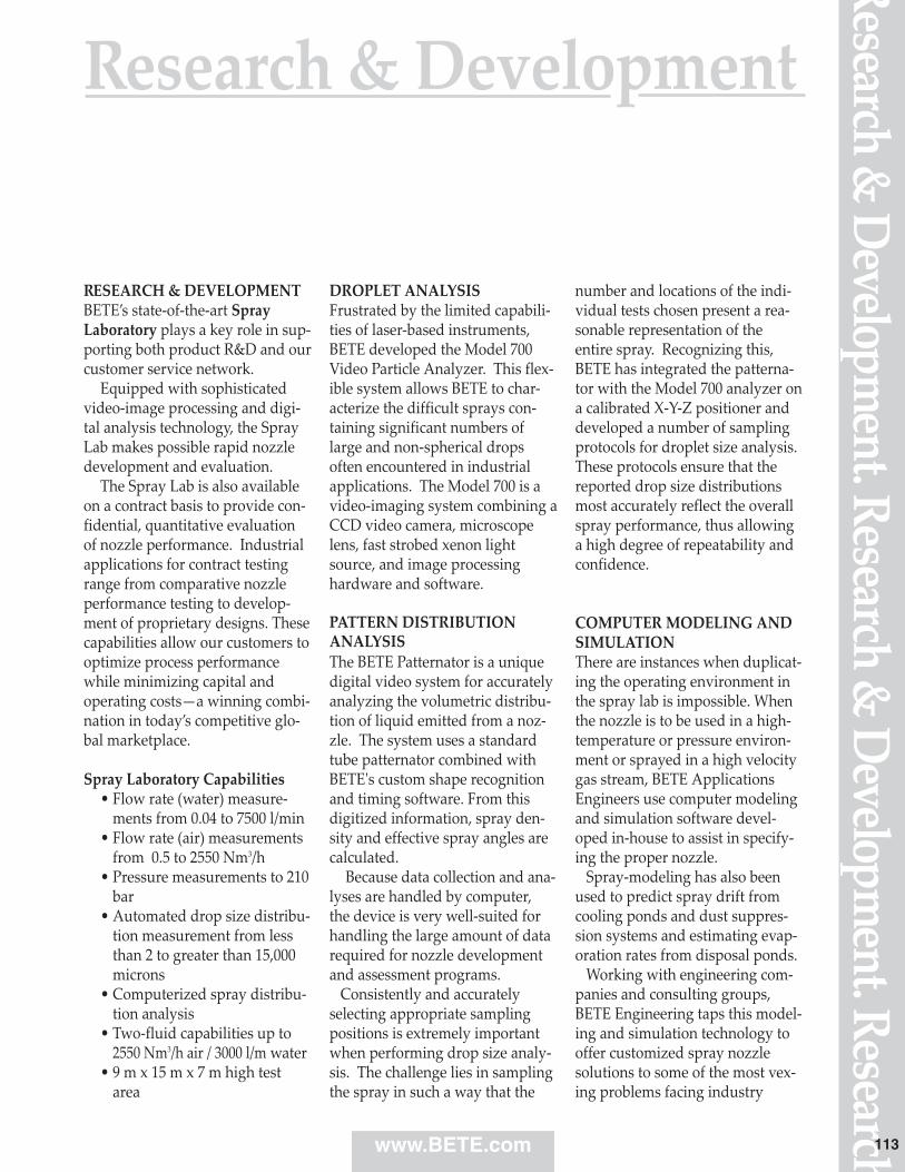
Research & D
evelopment. Research &
Developm
ent. Research
RESEARCH & DEVELOPMENTBETE’s state‑of‑the‑art Spray Laboratory plays a key role in sup‑porting both product R&D and ourcustomer service network.
Equipped with sophisticatedvideo‑image processing and digi‑tal analysis technology, the SprayLab makes possible rapid nozzledevelopment and evaluation.
The Spray Lab is also availableon a contract basis to provide con‑fidential, quantitative evaluationof nozzle performance. Industrialapplications for contract testingrange from comparative nozzleperformance testing to develop‑ment of proprietary designs. Thesecapabilities allow our customers tooptimize process performancewhile minimizing capital andoperating costs—a winning combi‑nation in today’s competitive glo‑bal marketplace.
Spray Laboratory Capabilities• Flow rate (water) measure‑
ments from 0.04 to 7500 l/min• Flow rate (air) measurements
from 0.5 to 2550 Nm3/h• Pressure measurements to 210
bar• Automated drop size distribu‑
tion measurement from lessthan 2 to greater than 15,000microns
• Computerized spray distribu‑tion analysis
• Two‑fluid capabilities up to2550 Nm3/h air / 3000 l/m water
• 9 m x 15 m x 7 m high testarea
DROPLET ANALYSISFrustrated by the limited capabili‑ties of laser‑based instruments,BETE developed the Model 700Video Particle Analyzer. This flex‑ible system allows BETE to char‑acterize the difficult sprays con‑taining significant numbers oflarge and non‑spherical dropsoften encountered in industrialapplications. The Model 700 is avideo‑imaging system combining aCCD video camera, microscopelens, fast strobed xenon lightsource, and image processinghardware and software.
PATTERN DISTRIBUTION ANALYSISThe BETE Patternator is a uniquedigital video system for accuratelyanalyzing the volumetric distribu‑tion of liquid emitted from a noz‑zle. The system uses a standardtube patternator combined withBETE's custom shape recognitionand timing software. From thisdigitized information, spray den‑sity and effective spray angles arecalculated.
Because data collection and ana‑lyses are handled by computer, the device is very well‑suited forhandling the large amount of datarequired for nozzle developmentand assessment programs.
Consistently and accuratelyselecting appropriate samplingpositions is extremely importantwhen performing drop size analy‑sis. The challenge lies in samplingthe spray in such a way that the
number and locations of the indi‑vidual tests chosen present a rea‑sonable representation of theentire spray. Recognizing this,BETE has integrated the patterna‑tor with the Model 700 analyzer ona calibrated X‑Y‑Z positioner anddeveloped a number of samplingprotocols for droplet size analysis.These protocols ensure that thereported drop size distributionsmost accurately reflect the overallspray performance, thus allowinga high degree of repeatability andconfidence.
COMPUTER MODELING ANDSIMULATIONThere are instances when duplicat‑ing the operating environment inthe spray lab is impossible. Whenthe nozzle is to be used in a high‑temperature or pressure environ‑ment or sprayed in a high velocitygas stream, BETE ApplicationsEngineers use computer modelingand simulation software devel‑oped in‑house to assist in specify‑ing the proper nozzle.
Spray‑modeling has also beenused to predict spray drift fromcooling ponds and dust suppres‑sion systems and estimating evap‑oration rates from disposal ponds.
Working with engineering com‑panies and consulting groups,BETE Engineering taps this model‑ing and simulation technology tooffer customized spray nozzlesolutions to some of the most vex‑ing problems facing industry
Research & Development
www.BETE.com 113
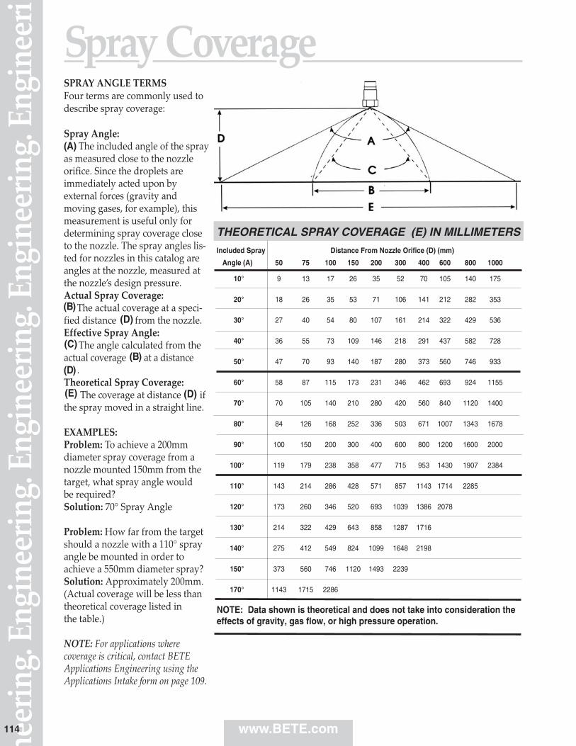
neer
ing.
Eng
inee
ring.
Eng
inee
ring.
Eng
inee
ring.
Eng
inee
riSpray CoverageSPRAY ANGLE TERMSFour terms are commonly used todescribe spray coverage:
Spray Angle:(A) The included angle of the sprayas measured close to the nozzleorifice. Since the droplets areimmediately acted upon byexternal forces (gravity andmoving gases, for example), thismeasurement is useful only fordetermining spray coverage closeto the nozzle. The spray angles lis‑ted for nozzles in this catalog areangles at the nozzle, measured atthe nozzle’s design pressure.Actual Spray Coverage:
The actual coverage at a speci‑fied distance from the nozzle.Effective Spray Angle:
The angle calculated from theactual coverage at a distance
.Theoretical Spray Coverage:
The coverage at distance ifthe spray moved in a straight line.
EXAMPLES:Problem: To achieve a 200mmdiameter spray coverage from anozzle mounted 150mm from thetarget, what spray angle would be required?Solution: 70° Spray Angle
Problem: How far from the targetshould a nozzle with a 110° sprayangle be mounted in order toachieve a 550mm diameter spray?Solution: Approximately 200mm.(Actual coverage will be less thantheoretical coverage listed in the table.)
NOTE: For applications wherecoverage is critical, contact BETEApplications Engineering using theApplications Intake form on page 109.
(B)(D)
(C)(B)
(D)
(D)
(E)
THEORETICAL SPRAY COVERAGE (E) IN MILLIMETERSIncluded Spray Distance From Nozzle Orifice (D) (mm)
Angle (A) 50 75 100 150 200 300 400 600 800 1000
10° 9 13 17 26 35 52 70 105 140 175
20° 18 26 35 53 71 106 141 212 282 353
30° 27 40 54 80 107 161 214 322 429 536
40° 36 55 73 109 146 218 291 437 582 728
50° 47 70 93 140 187 280 373 560 746 933
60° 58 87 115 173 231 346 462 693 924 1155
70° 70 105 140 210 280 420 560 840 1120 1400
80° 84 126 168 252 336 503 671 1007 1343 1678
90° 100 150 200 300 400 600 800 1200 1600 2000
100° 119 179 238 358 477 715 953 1430 1907 2384
110° 143 214 286 428 571 857 1143 1714 2285
120° 173 260 346 520 693 1039 1386 2078
130° 214 322 429 643 858 1287 1716
140° 275 412 549 824 1099 1648 2198
150° 373 560 746 1120 1493 2239
170° 1143 1715 2286
NOTE: Data shown is theoretical and does not take into consideration theeffects of gravity, gas flow, or high pressure operation.
www.BETE.com114
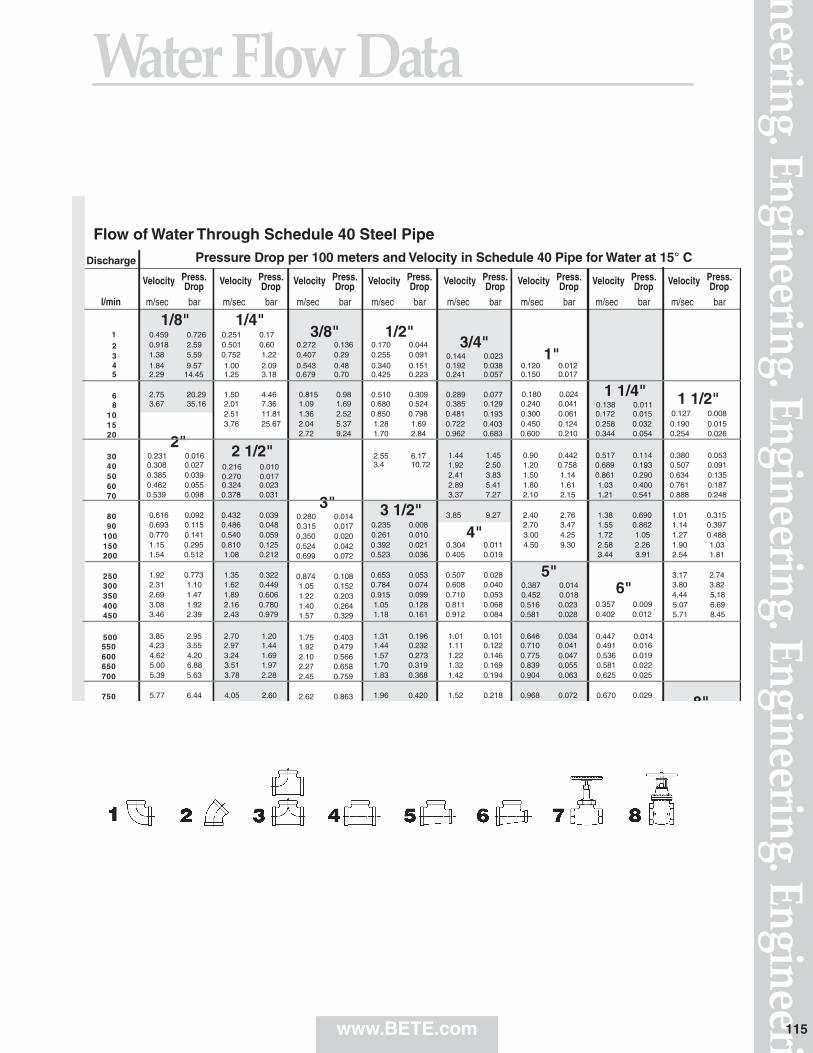
neering. Engineering. Engineering. Engineering. EngineeriWater Flow Data
www.BETE.com 115
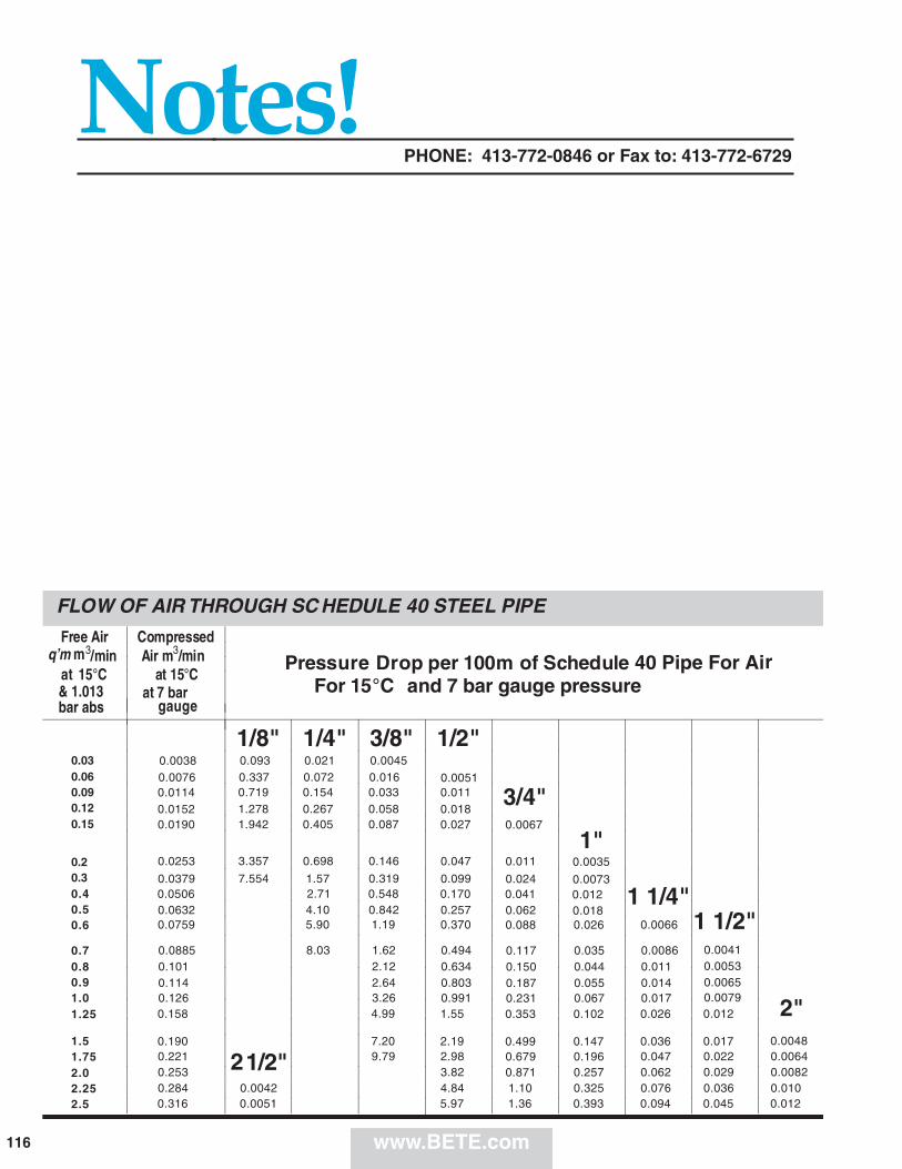
Notes!PHONE: 413-772-0846 or Fax to: 413-772-6729
www.BETE.com116
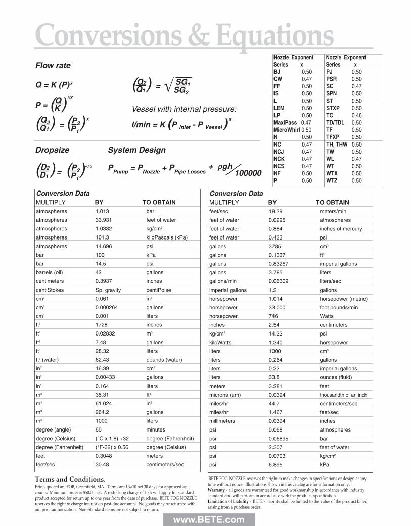
Flow rate
Q = K (P) x
P = (Q)1/X
K
(Q2)Q1 = (P2) X
P1
(Q2)Q1 = √ SG1
SG2
Vessel with internal pressure:
l/min = K (P inlet - P Vessel )x
Terms and Conditions.Prices quoted are FOB, Greenfield, MA. Terms are 1%/10 net 30 days for approved ac-counts. Minimum order is $50.00 net. A restocking charge of 15% will apply for standardproduct accepted for return up to one year from the date of purchase. BETE FOG NOZZLEreserves the right to charge interest on past-due accounts. No goods may be returned with-out prior authorization. Non-Standard items are not subject to return.
BETE FOG NOZZLE reserves the right to make changes in specifications or design at anytime without notice. Illustrations shown in this catalog are for information only.Warranty - all goods are warranteed for good workmanship in accordance with industrystandard and will perform in accordance with the products specification.Limitation of Liability - BETE’s liability shall be limited to the value of the product billedarising from a purchase order.
Conversion DataMULTIPLY BY TO OBTAINfeet/sec 18.29 meters/min
feet of water 0.0295 atmospheres
feet of water 0.884 inches of mercury
feet of water 0.433 psi
gallons 3785 cm3
gallons 0.1337 ft3
gallons 0.83267 imperial gallons
gallons 3.785 liters
gallons/min 0.06309 liters/sec
imperial gallons 1.2 gallons
horsepower 1.014 horsepower (metric)
horsepower 33.000 foot pounds/min
horsepower 746 Watts
inches 2.54 centimeters
kg/cm2 14.22 psi
kiloWatts 1.340 horsepower
liters 1000 cm3
liters 0.264 gallons
liters 0.22 imperial gallons
liters 33.8 ounces (fluid)
meters 3.281 feet
microns (µm) 0.0394 thousandth of an inch
miles/hr 44.7 centimeters/sec
miles/hr 1.467 feet/sec
millimeters 0.0394 inches
psi 0.068 atmospheres
psi 0.06895 bar
psi 2.307 feet of water
psi 0.0703 kg/cm2
psi 6.895 kPa
Conversion DataMULTIPLY BY TO OBTAINatmospheres 1.013 bar
atmospheres 33.931 feet of water
atmospheres 1.0332 kg/cm2
atmospheres 101.3 kiloPascals (kPa)
atmospheres 14.696 psi
bar 100 kPa
bar 14.5 psi
barrels (oil) 42 gallons
centimeters 0.3937 inches
centiStokes Sp. gravity centiPoise
cm3 0.061 in3
cm3 0.000264 gallons
cm3 0.001 liters
ft3 1728 inches
ft3 0.02832 m3
ft3 7.48 gallons
ft3 28.32 liters
ft3 (water) 62.43 pounds (water)
in3 16.39 cm3
in3 0.00433 gallons
in3 0.164 liters
m3 35.31 ft3
m3 61.024 in3
m3 264.2 gallons
m3 1000 liters
degree (angle) 60 minutes
degree (Celsius) (°C x 1.8) +32 degree (Fahrenheit)
degree (Fahrenheit) (°F-32) x 0.56 degree (Celsius)
feet 0.3048 meters
feet/sec 30.48 centimeters/sec
Nozzle Exponent Nozzle ExponentSeries x Series xBJ 0.50 PJ 0.50CW 0.47 PSR 0.50FF 0.50 SC 0.47IS 0.50 SPN 0.50L 0.50 ST 0.50LEM 0.50 STXP 0.50LP 0.50 TC 0.46MaxiPass 0.47 TD/TDL 0.50MicroWhirl 0.50 TF 0.50N 0.50 TFXP 0.50NC 0.47 TH, THW 0.50NCJ 0.47 TW 0.50NCK 0.47 WL 0.47NCS 0.47 WT 0.50NF 0.50 WTX 0.50P 0.50 WTZ 0.50
Dropsize System Design
(D2D1
) = (P2)-0.3 PPump = PNozzle + PPipe Losses + ρρgh
100000P1
www.BETE.com
Conversions & EquationsTable of Contents
With thousands of different spray nozzles available in hundreds of different materials, it’s often hard to know where to start. So, we’ve incorporated a number of uniquecharts and other aids into this catalog to simplify your selection process.
Still unsure of which nozzle to use? We can help. Use the BETEApplication Intake Sheet on page 109 to describe your application to our engineers. We’ll put our years of experience to work on yourproblem and respond quickly with a recommendation.
120METRIC
Cover photography by Ed Judice and Greg Bardwell.
Payment with Visa, Mastercard and AmericanExpress accepted.
a b d
Nozzle Selection GuideHow to order
There are many ways to select a nozzle. Which way is right for you?
Do you know the spray pattern, but not the type of nozzle?..................see pages 2, 3This section introduces you to the several types of spray nozzles and the spray patterns available from each.
Do you know what style of nozzle is right for you but need help differentiating betweenthe many nozzle series in each style?..........................................................see pages 4, 5Organized by nozzle style, this section briefly describes each nozzle series
Want to see what nozzles excel at your specific application?.................see pages 6-12An alphabetical list of common applications and the nozzles that are used most frequently for each.
Still not sure? Don’t have time to look? Call us. BETE’s Customer Service Representatives and Application Engineers will listen to your problem and guide you to the nozzle you need.Let our expertise save you time and keep your process running at peak efficiency.
www.bete.com
BY SPRAY PATTERN....PP. 2, 3
BY NOZZLE TYPE....PP. 4, 5
BY APPLICATION....PP. 6-12
1-800-235-00491-413-772-0846
©2007 BETE Fog Nozzle, Inc. All rights reserved.

50 Greenfield StreetGreenfield, MA 01301T (413) 772-0846 F (413) 772-6729Email: [email protected]
BETE Fog Nozzle, Inc.
PERFORMANCE THROUGH ENGINEERING
ABSORPTION • ADDITIVES • AERATION • AIR AND STEAM • AIR CONDITIONING • AIR NOZZLES
• BIODIESEL • BLOWOFF NOZZLES • CLEAN-IN-PLACE NOZZLES • CLOG-RESISTANT NOZZLES
• COATING • CONCRETE CURING • COOLING • DISTRIBUTION • DRYING • DUST CONTROL
• ETCHING • EVAPORATIVE COOLING • EVAPORATIVE DISPOSAL • FIRE PROTECTION • FLUE GAS
DESULPHURIZATION • FOAM CONTROL • FOG NOZZLES • FOOD PROCESSING • GAS SCRUBBING
• HUMIDIFICATION • LUBRICATION • MIST ELIMINATOR WASH • MISTING • MIXING
EDUCTORS • MOISTENING • ODOR CONTROL • PACKING • PARTS WASHING
• PETROLEUM PROCESSING • POLLUTION CONTROL • PULP BLEACHING • QUENCH
• ROLL COOLING • SCRUBBING • SPRAY DRYING • TANK WASHING • WASTEWATER TREATMENT
0707 10K 120METRIC
www.bete.com
ww
w.b
ete.com
IN
DU
STRIA
L SPRA
Y N
OZZLES
120METR
IC Prin
ted in
U.S.A
.