Embed Size (px)
Citation preview

BSOLUTE ROCESS NSTRUMENTS, Inc.
Company Philosophy
Our Company
History
api-usa.com 11220 American Way Libertyville, IL 60048Phone: 800-942-0315 Fax: 800-949-7502
Absolute Process Instruments Inc.
© 01-07
We are an engineering-oriented and application-driven company that providessolutions to our customers’ technical problems. All of our API and Cecomp man-ufactured products are designed by our engineering staff and assembled in ourLibertyville facility. We have also formed strategic alliances with companies inAustralia, Germany, and Switzerland in order to broaden our product offering aswell as opening channels for serving overseas markets.
Absolute Process Instruments designs and manufactures industrial electronicsin a broad range of industries, including machinery manufacturing, automotive,dairy, and factory automation and control. Products include
■ Microprocessor-based controls
■ Vacuum and pressure measurement and control instruments
■ Temperature measurement and control products
■ Flow measurement and control systems
■ Motion control products
■ DC/AC/Servo motor drives
■ Signal processing equipment
■ Data logging and measurement instruments.
Our products range from board level through complete products such asportable computers and hand-held instrumentation.
We are committed to providing high quality products at affordable prices alongwith expert application assistance and quick delivery. This provides our cus-tomers with the benefits of increased productivity while backing our productswith a total commitment to customer service and support.
When you call us you will talk to a real person, not an automated help line. Ourcustomer service staff is trained to not only answer questions about our prod-ucts, but to provide technical assistance and solutions to your application ques-tions.
We continue to maintain our reputation for being a company that is “easy to dealwith” by offering solutions to your application challenges and providing highquality economical products with timely delivery.
Product improvements and enhancements as well as new product developmentoften start with information from the field. We encourage customer feedback onour product lines. We feel this provides an opportunity to serve your specialrequirements.
At API we measure our performance by our ability to provide the right productfor a customer’s application in a timely manner. Our approach to each businessopportunity is summarized as follows:
Facta non VFacta non Verbaerba
Deeds not WDeeds not Worordsds
Absolute Process Instruments Inc. (API), was founded in 1987 as a designerand manufacturer of signal conditioning and signal interface products for theindustrial marketplace. API has grown to become a market leader in custom sig-nal conditioning products.
Cecomp Electronics, Inc. was founded in 1983, as a “Custom ElectronicsCompany” hence the name Cecomp. Cecomp is a diverse designer and manu-facturer of a wide variety of standard and custom electronic products. Cecompspecializes in pressure/vacuum test, measurement and process control instru-mentation as well as custom electronic products and contract manufacturing.Cecomp joined the API family in 1995 and in 1998 began to produce its highlyregarded line of digital pressure gauges.
Cecomp became a division of API in 2000 at which time both companies movedto a new 12,500 square foot building in Libertyville, Illinois. This new headquar-ters and manufacturing facility is expected to accommodate the growth of APIwith state-of-the-art equipment, highly skilled engineers and staff, and innova-tive ideas. API will continue to be a leading manufacturer of signal conditioningproducts, digital pressure gauges, and custom electronics.
Absolute Process Instruments and Cecomp Electronics products are manufac-tured in the USA with extensive electronic circuit design, development and man-ufacturing experience in both thru-hole and fully automated SMT (SurfaceMount Technology) production equipment.
In 2002, Absolute Process Instruments and Camille Bauer based in Wohlen,Switzerland formed a strategic alliance for their industrial process products withthe newly formed API-Camille Bauer Division to exclusively promote, serviceand sell Camille Bauer products in North America. These products will comple-ment and expand the product lines manufactured by API.
This partnership will continue the tradition of excellent product support, compet-itive prices, and fast delivery for the Camille Bauer SINEAX high performancesignal conditioning, KINAX position transducers and SINEAX electric powermeasurement products.
In 2003, Absolute Process Instruments and RheinTacho Messtechnik GmbH ofFreiburg, Germany formed an alliance to exclusively promote, service and selltheir non-contact speed sensors and programmable speed monitors in NorthAmerica. These products also complement and expand the product lines man-ufactured by API and those sold by the API-Camille Bauer Division.
Quality plays a primary role at API. This is achieved through excellent manufac-turing practices, investment in the latest equipment, and a dedicated stableworkforce. Quality people mean quality products at API. Our confident in ourmanufacturing quality allows us to offer a lifetime warranty on API signal condi-tioners. Every product is tested before it is shipped. NIST traceable standardsensure accuracy.
Quality
We are dedicated to maintaining quality field support by utilizing independentsales representatives within defined territories. We value these organizationsand consider them extensions of our company when dealing with our cus-tomers. Through these organizations, we are able to offer in-depth customerservice, not only via technical support, but by striving to build long term relation-ships.
We also support a North American distributor network many of whom special-ize in certain industries and stock our products. We also serve our worldwidecustomers via our industrial product exporters. Contact us to find a representa-tive or distributor near you or visit our web sites.
api-usa.com cecomp.com
apicb.com rheintacho.us
Markets Served
API Info

Absolute Process Instruments, Inc.
BSOLUTE ROCESS NSTRUMENTS, Inc. api-usa.com © 01-0721220 American Way Libertyville, IL 60048Phone: 800-942-0315 Fax: 800-949-7502
ProductsAbsolute Process Instruments, Inc.❏ Manufactures a complete line of industrial signal conditioners, signal con-
verters, alarms, signal transmitters, temperature alarms and transmitters
❏ Engineers and manufactures custom signal conditioning products
Cecomp Electronics Division❏ Manufactures digital pressure and vacuum gauges, transmitters, pressure
switches and alarms
❏ Manufactures digital temperature products and transmitters
❏ Engineers and manufactures custom and private label electronic products
Api-Camille Bauer Division❏ Industrial signal conditioners, signal converters, alarm relays, signal trans-
mitters, temperature alarms and transmitters from Switzerland
❏ SINEAX electrical power monitors and transducers, including models withMODBUS, PROFIBUS and Hart communications
❏ KINAX ruggedized capacitive-type rotary position transducers
❏ LINEAX chart recorders and supplies
❏ RheinTacho non-contact speed sensors and programmable speed monitors
❏ APCS specialty signal conditioners and signal interface products fromAustralia
New Products
API custom products include microprocessor controls, vacuum and pressuremeasurement and control, temperature measurement and control, flow meas-urement and control, motion control, DC/AC/servo motor drives, signal process-ing, and data logging and measurement. Our products range from board levelthrough complete products such as portable computers and hand-held instru-mentation.
We are an engineering-oriented and application-driven company that providessolutions to our customers’ technical problems. All of our API and Cecomp man-ufactured products are designed by our engineering staff and assembled in ourLibertyville facility.
In-house engineering capabilities include circuit design, software design, print-ed circuit board layout, prototype assembly, qualification testing, and documen-tation. Our in-house manufacturing process (UL/CUL Certified Shop) includesautomated surface mount assembly equipment, as well as testing and calibra-tion equipment (NIST traceable pressure and voltage standards) allowing eco-nomical custom products, fast delivery, and excellent quality.
We also offer cost-reduction, miniaturization, design review, and consultingservices for product redesign or updates. Mechanical design and finished prod-uct testing when combined with the design capabilities listed above allows APIto offer full turnkey electronic design and manufacturing services to a widerange of industrial OEM markets. We are often able to quote projects involvingfewer than 1000 units per year.
Absolute Process Instruments has designed and manufactured industrial elec-tronics in a broad range of industries, including machinery manufacturers, auto-motive, aviation, dairy, and factory automation and control.
Please call us at 800-942-0315 to discuss your OEM project!
Custom Manufacturing
API I
nfo
2000 DuoPak® Dual channel isolators/converters/transmitters p. 19
APCS Specialty signal conditioners p. 23-24
CAM Series High speed power monitors p. 49
CTX-AC Series Non-RMS current transducers p. 59-62
4300 DIN API 4300 in DIN housing p. 97
4393 DIN EX New IsoSplitter® signal splitter versions p. 125
B 812 Loop Power Supply p. 144
F16L Series Programmable pressure transmitter p. 193
F16ADA Series Programmable pressure switches p. 201
F16ADAH Series Programmable pressure switches p. 203
Speed Sensors Rotational speed sensors p. 208
ThermoPro® Programmable temperature transmitter p. 243
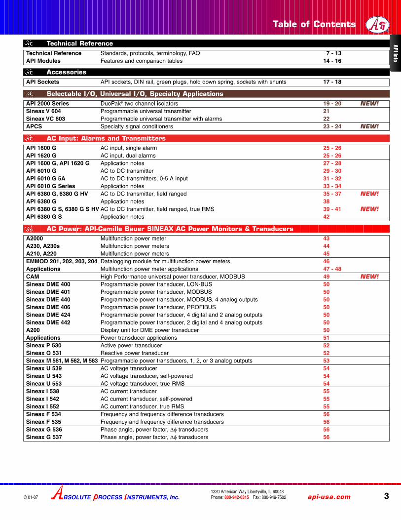
Table of Contents
BSOLUTE ROCESS NSTRUMENTS, Inc. api-usa.com 31220 American Way Libertyville, IL 60048Phone: 800-942-0315 Fax: 800-949-7502© 01-07
API 2000 Series DuoPak® two channel isolators 19 - 20 NEW!NEW!Sineax V 604 Programmable universal transmitter 21Sineax VC 603 Programmable universal transmitter with alarms 22APCS Specialty signal conditioners 23 - 24 NEW!NEW!
Selectable I/O, Universal I/O, Specialty Applications
AccessoriesAPI Sockets API sockets, DIN rail, green plugs, hold down spring, sockets with shunts 17 - 18
Technical Reference Standards, protocols, terminology, FAQ 7 - 13API Modules Features and comparison tables 14 - 16
Technical Reference API Info
A2000 Multifunction power meter 43A230, A230s Multifunction power meters 44A210, A220 Multifunction power meters 45EMMOD 201, 202, 203, 204 Datalogging module for multifunction power meters 46Applications Multifunction power meter applications 47 - 48CAM High Performance universal power transducer, MODBUS 49 NEW!NEW!Sineax DME 400 Programmable power transducer, LON-BUS 50Sineax DME 401 Programmable power transducer, MODBUS 50Sineax DME 440 Programmable power transducer, MODBUS, 4 analog outputs 50Sineax DME 406 Programmable power transducer, PROFIBUS 50Sineax DME 424 Programmable power transducer, 4 digital and 2 analog outputs 50Sineax DME 442 Programmable power transducer, 2 digital and 4 analog outputs 50A200 Display unit for DME power transducer 50Applications Power transducer applications 51Sineax P 530 Active power transducer 52Sineax Q 531 Reactive power transducer 52Sineax M 561, M 562, M 563 Programmable power transducers, 1, 2, or 3 analog outputs 53Sineax U 539 AC voltage transducer 54Sineax U 543 AC voltage transducer, self-powered 54Sineax U 553 AC voltage transducer, true RMS 54Sineax I 538 AC current transducer 55Sineax I 542 AC current transducer, self-powered 55Sineax I 552 AC current transducer, true RMS 55Sineax F 534 Frequency and frequency difference transducers 56Sineax F 535 Frequency and frequency difference transducers 56Sineax G 536 Phase angle, power factor, Δφ transducers 56Sineax G 537 Phase angle, power factor, Δφ transducers 56
AC Power: API-Camille Bauer SINEAX AC Power Monitors & Transducers
AC Input: Alarms and TransmittersAPI 1600 G AC input, single alarm 25 - 26API 1620 G AC input, dual alarms 25 - 26API 1600 G, API 1620 G Application notes 27 - 28API 6010 G AC to DC transmitter 29 - 30API 6010 G 5A AC to DC transmitters, 0-5 A input 31 - 32API 6010 G Series Application notes 33 - 34API 6380 G, 6380 G HV AC to DC transmitter, field ranged 35 - 37 NEW!NEW!API 6380 G Application notes 38API 6380 G S, 6380 G S HV AC to DC transmitter, field ranged, true RMS 39 - 41 NEW!NEW!API 6380 G S Application notes 42

4
Table of Contents
© 01-07BSOLUTE ROCESS NSTRUMENTS, Inc.1220 American Way Libertyville, IL 60048Phone: 800-942-0315 Fax: 800-949-7502
For latest product information or to contact yourlocal representative visit api-usa.com
Cont
ents
DC Input: Signal Converters, Isolators, Repeaters, Transmitters, Signal SplittersAPI 4300 G Isolated DC-DC transmitter 91 - 92API 4300 G Application notes 93 - 96API 4300 DIN Isolated DC-DC transmitter, DIN 97 - 98 NEW!NEW!API 4300 DD Isolated DC-DC transmitter, DIN 97 - 98 NEW!NEW!API 4310 G Isolated DC-DC transmitter, narrow input span 99 - 100API 4380 G Isolated DC-DC transmitter, field rangeable 101 - 103API 4380 G Application notes 104API 4380 G HV3 Isolated DC-DC transmitter, field rangeable, high voltage input 105 - 107API 4380 Series Application notes 108API 4380 DIN Isolated DC-DC transmitter, field rangeable, DIN 109 - 111API 4380 DD Isolated DC-DC transmitter, field rangeable, DIN, DC powered 109 - 111API 4380 DIN, DD Application notes 112API 4385 G Isolated DC-DC transmitter, field rangeable, non-interactive zero and span 113 - 115API 4385 G Application notes 116API DPI HV-DC Isolated DC-DC transmitter, field rangeable, DIN, high voltage input 117 - 118Sineax TV 809 Programmable DC isolator with alarm 119Sineax TV 808 DC isolator, 1 channel/2 channel amplifier/splitter 120Sineax TV 819 DC isolator, unipolar, bipolar 120API 4390 DIN 2-channel signal isolators, DIN 121 - 122API 4391 DIN 2-channel signal isolators, DIN 121 - 122API 4392 DIN 2-channel signal isolators, DIN 121 - 122
Introduction Product summary, AC and DC current transducers 57AL, 5RL, 7RL, 8RL Current transformers (CT) 58CTX-ACR-0, -1, -2 True RMS AC current transmitters, split core 59 - 60CTX-AC-0, -1, -2 AC current transmitters split core 59 - 60 NEW!NEW!CTX-ACR-3S, -4S True RMS AC current transmitters, solid core, high current 61 - 62CTX-AC-3S, -4S AC current transmitters, solid core, high current 61 - 62 NEW!NEW!CS-AC-1, -2 AC current switches, split core 63 - 64
AC Current Transmitters and Switches
CTX-DC-0, -1, -2, -3 DC current transmitters split core 67 - 68CS-DC-1S, -2S DC current switches solid core 69 - 70API 1000 G Single setpoint alarm trip 71 - 72API 1020 G Dual setpoint alarm trip 71 - 72API 1000 G, 1020 G Application notes 73 - 74API 1005 G Single setpoint alarm trip with loop power supply 75 - 76API 1025 G Dual setpoint alarm trip with loop power supply 75 - 76API 1040 G Single setpoint trip with DC transmitter 77 - 78API 1040 G, 1080 G Application notes 79 - 80API 1080 G Single setpoint alarm trip, field selectable 81 - 82API 1080 DIN Single setpoint alarm trip, field selectable, DIN 83 - 84API 1080 G, 1090 G Application notes 85 - 86API 1090 G Dual setpoint alarm trip, field selectable 87 - 88API 1090 DIN, 1090 DD Dual setpoint alarm trip, field selectable, DIN 89 - 90
DC Input: DC Current Sensors, DC Input Alarms, Trips, Switches
Angular Position: API-Camille Bauer KINAX Angular Position TransducersKinax 3W2 Angular position transducer 65Kinax WT-710 Heavy duty angular position transducer 65Kinax WT-707 Heavy duty angular position transducer 65Kinax SR-709 Heavy duty linear position transducer 65Kinax 2W2 Programmable angular position transducer 66Kinax WT-711 Programmable heavy duty angular transducer 66Kinax WT-717 Programmable heavy duty angular transducer 66Kinax SR-719 Programmable heavy duty linear transducer 66

Table of Contents
BSOLUTE ROCESS NSTRUMENTS, Inc. api-usa.com 51220 American Way Libertyville, IL 60048Phone: 800-942-0315 Fax: 800-949-7502© 01-07
Frequency Input: Alarms, Frequency Input and Output TransmittersAPI 1700 G Frequency input, single alarm 145 - 146API 1720 G Frequency input, dual alarms 145 - 146API 7010 G Frequency to DC transmitter 147 - 148API 7010 G Application notes 149 - 150API 7500 G DC to frequency transmitter, field rangeable 151 - 152API 7500 G Application notes 153 - 154API 7500 G SS DC to frequency transmitter, field rangeable, low frequency 155 - 156API 7580 G Frequency to DC transmitter, field rangeable 157 - 158API 7580 G Application notes 159 - 160
Contents
API 4393 DIN IsoSplitter®, signal isolator/splitter, 1 in-2 out, DIN 123 - 124API 4393 L1 Series IsoSplitter, signal isolator/splitter, 1 in-2 out, DIN, 4-20 mA 125 - 126API 4393 Series Application notes 127 - 128Sineax DCM 817 Loop-powered signal isolator, PCB mount 129Sineax TI 816 Loop-powered signal isolator 129Sineax SI 815 Loop-powered power transfer signal isolator 130Sineax TI 807 Loop-powered signal isolator, 1, 2, or 3 channel 130API LPI-1 Loop-powered 4-20 mA isolator, single channel 131 - 132API LPI-2 Loop-powered 4-20 mA isolator, dual channel 131 - 132API LPI-1, LPI-2 Application notes 133 - 134API DPI-2 Loop-powered 4-20 mA isolator, dual channel, DIN 135 - 136
Pressure Information Pressure conversions, typical gauge ranges, altitude correction 167Technical Information Range selection, cavity volume, alarms, gauge reference options, retransmission 168Gauge FAQ Cecomp gauge frequently asked questions 169Gauge Range Tables Cecomp gauge ranges, engineering units, accuracy 170 - 172Gauge Applications Application notes 173CC Conformal coating 174ET Extended temperature display 174PM, PMS, SM Gauge mounting options 174HA, 4A Accuracy options 174400 Display 4-digit display option 174NIST, CD Calibration data options 174RB, MC Rubber boot, Metal cover 174WMPSK, 9046-24-008 Gauge and loop power supplies 174DPG1000B Series Battery-powered digital pressure gauges 175 - 176F4B Series Digi Pro4® Battery-powered digital pressure gauges, NEMA 4X 177 - 178F16B Series Digi Max® Battery-powered digital pressure gauges, min/max reading 179 - 180
Pressure: Cecomp Pressure Products
DC Input: Signal Isolators, Splitters, Loop Isolators
DC Input: Math and Square Root ModulesAPI 440X G Series Addition / subtraction / averaging modules 137 - 138API 440X G , 4440 G Application notes 139 - 140API 4440 G DC to DC transmitter square root extractor 141 - 142
DC Power SuppliesAPI 9046 Series DC Regulated Power Supplies 143API 9046-CH Series DC Regulated Power Supplies, bipolar output 143Sineax B 812 Loop power supply 144 NEW!NEW!Sineax B 840 Loop power supply, up to 4 loops 144
Potentiometer Input: Alarms and TransmittersAPI 4003 G I Potentiometer input to DC transmitter 161 - 162API 4003 G I Application notes 163 - 164API 4008 G Potentiometer input to DC transmitter, field rangeable 165 - 166

BSOLUTE ROCESS NSTRUMENTS, Inc. api-usa.com61220 American Way Libertyville, IL 60048Phone: 800-942-0315 Fax: 800-949-7502
Table of Contents
© 01-07
Cont
ents
API 1200 G T/C input, single alarm 227 - 228API 1220 G T/C input, dual alarms 227 - 228API 1200 G, 1400 G Application notes, T/C specifications 229 - 230API 1420 G, API 4130 GL Application notes, FAQ 230API 1400 G RTD input, single alarm 231 - 232API 1420 G RTD input, dual alarms 231 - 232API 4001 G L RTD transmitter, isolated 233 - 234API 4001 G SA-B Differential RTD transmitter 235 - 236API 4001 G SA-B Application notes 237Sineax V 608 Programmable temperature transmitter, T/C, RTD 238Sineax V 611 Programmable temperature transmitter, T/C, RTD 238Sineax VK 616 Programmable head mount temperature transmitter, T/C, RTD 239Sineax VK 626 HART head mount temperature transmitter, T/C, RTD 239Sineax VK 636 PROFIBUS head mount temperature transmitter, T/C, RTD 239Sineax V 624 Programmable temperature transmitter, T/C, RTD 240Sineax V 624 Application note, V 624 cold junction compensation 240API 4130 GL T/C transmitter, isolated 241 - 242ThermoPro® Cecomp ThermoPro indicating RTD temperature transmitter, programmable 243 - 244 NEW!NEW!
Temperature Input, RTD, Thermistor, T/C
Valve Drivers, Math Functions, P-I ConvertersAPI 3200 G Valve actuator / positioner / controller 245 - 246API 3200 G Application notes 247 - 248
RheinTacho Programmable Speed MonitorsCR, CRR, CRA, CRRA Rotational speed monitors, programmable 207SH, SD, SM, SO, SIS Rotational speed sensors, Hall and magnetic 208 NEW!NEW!
Strain Gauge, Bridge, or Load Cell Input Transmitter and Sum BoxesAPI 4051 G Bridge input, DC transmitter 209 - 210API 4051 G Application notes 211 - 212API 4058 G Bridge input, DC transmitter, field ranged, non-isolated 213 - 215API 4059 G Application notes 216API 4059 G Bridge input, DC transmitter, field ranged, isolated 217 - 219API 4059 G Application notes 220API 4059 DIN Bridge input, DC transmitter, field ranged, isolated, DIN 221 - 223API 4059 DD Bridge input, DC transmitter, field ranged, isolated, DIN 221 - 223API 405x Series Application notes, load cell color codes 224API SUM Summing board assembly 225 - 226
ARM760B Series Battery-powered digital 760 torr absolute manometers 181 - 182ARM760AD Series Low voltage-powered digital 760 torr absolute manometers 181 - 182DPG1000AD Series Low voltage-powered digital pressure gauges 183 - 184F4AD Series Low voltage-powered digital pressure gauges, NEMA 4X 185 - 186F16AD Series Low voltage-powered digital pressure gauges, min/max reading 187 - 188DPG1000L 2-wire 4-20 mA loop-powered indicating pressure transmitters 189 - 190F4L 2-wire 4-20 mA loop-powered indicating pressure transmitters, NEMA 4X 191 - 192F16L, F16LN 2-wire 4-20 mA loop-powered indicating pressure transmitters, programmable 193 - 194 NEW!NEW!DPG1000DR Series Low voltage-powered indicating pressure transmitters 195 - 196F4DR Series Low voltage-powered indicating pressure transmitters, NEMA 4X 197 - 198DPG1000ADA Low voltage-powered digital pressure gauges with alarms 199 - 200F16ADA Low voltage-powered digital pressure gauges with alarms, programmable 201 - 202 NEW!NEW!F16ADAH Low voltage-powered digital pressure gauges, relays, adj. hysteresis, programmable 203 - 204 NEW!NEW!DPG1000DAR Low voltage-powered indicating pressure transmitters with alarms 205 - 206
Pressure: Cecomp Pressure Products

Technical Reference
BSOLUTE ROCESS NSTRUMENTS, Inc. api-usa.com 71220 American Way Libertyville, IL 60048Phone: 800-942-0315 Fax: 800-949-7502© 01-07
Accuracy Class (ansi.org, ieee.org, iec.ch, iso.ch, nist.gov)Error in an instrument or sensor is typically made up of several combined fac-tors such as linearity, hysteresis, repeatability, temperature effects, etc.Standards organizations such as ANSI, IEC, IEEE, ISO, NIST have summarizedaccuracies for various types of products into numbered or lettered classes anddefined the conditions under which these accuracy standards apply. Typicalaccuracy classes for current transformers are listed below.
CE newapproach.orgThe CE (Conformite Europeenne) mark is an indication that a compa-ny has met the essential heath, safety and environmental requirementsdetailed in European Union directives covering an array of industrial and con-sumer products. Once a company has met these requirements, it can affix theCE mark to its products and sell them throughout the European Union.
CSA csa.caThe Canadian Standards Association develops standards to enhancepublic safety, health, and the environment. CSA standards cover anarray of industrial and consumer products, and are harmonized withNorth American and international requirements wherever practical.The “C” and “US” indicate compliance with both Canadian and U.S.requirements.
GL gl-group.comGermanischer Lloyd approved for shipboard installations. GL is anindependent, non-profit organization setting safety and quality stan-dards for ships and marine equipment.
NEMA nema.orgThe National Electrical Manufacturers Association (NEMA®) promotes stan-dardization of electrical equipment, enabling consumers to select from a rangeof safe, effective, and compatible electrical products. See table below for hous-ing classifications.
UL ul.comUnderwriters Laboratories Inc. (UL) is a product safety testingand certification organization covering an array of industrial andconsumer products. Recognized Component Mark for Canadaand the United States may be used on components certified byUL to both Canadian and U.S. requirements. RecognizedComponent Mark for the United States may be used on compo-nents certified by UL to U.S. requirements.
GL
C US
Type Protection Location Description IP*1 General Purpose Indoor Accidental contact IP 102 Drip-Proof Indoor Falling non-corrosive liquids and falling dirt IP 113 Dust-tight Rain-tight Outdoor Windblown dust, water, and sleet; ice-resistant IP 54
3R Dust-tight Rain-tight Outdoor As above, plus melting sleet/ice will not damage external enclosure or mechanisms IP 144 Water-tight Dust-tight Indoor/Outdoor Splashing water, outdoor seepage of water, falling or hose-directed water IP 56
4X Water-tight Dust-tight Indoor As above, plus corrosion resistant IP 565 Dust-tight Indoor Dust and falling dirt IP 526 Water-tight Dust-tight Indoor/Outdoor Temporary entry of water limited submersion, formation of ice on enclosure IP 67
6P Water-tight Dust-tight Indoor/Outdoor As above, plus prolonged submersion IP 677 Explosion proof Class I Group D Hazardous Locations Indoor Hazardous chemicals and gases n/a9 Explosion proof Class II Hazardous Locations Indoor Hazardous dust n/a11 Drip-proof & Corrosion Resistant Indoor Oil immersion, corrosive effects of liquids and gases n/a12 Drip-tight Dust-tight Indoor Fibers, lint, dust, and splashing and dripping condensation of non-corrosive liquids IP 5213 Oil-tight Dust-tight Indoor Dust, spraying of water, oil, and non-corrosive coolant IP 54
NEMA Enclosure Ratings nema.org
TypicalApplication
AccuracyClass
Error at percent of rated current5% 20% 100% 120%
Precision testing 0.1 ±0.4% ±0.2% ±0.1% ±0.1%High accuracy
indication0.2 ±0.75% ±0.35% ±0.2% ±0.2%
Commercial andindustrial metering
0.5 ±1.5% ±1.5% ±0.5% ±0.5%
General purposemeasurements
1 ±3.0% ±3.0% ±1.0% ±1.0%
Approximate measurements
3 ±3.0% at 50% rated current ±3.0%
5 ±5.0% at 50% rated current ±5.0%
IP (Ingress Protection) Rating for Equipment and Enclosures iec.chIEC 60529 outlines the classification system for sealing effectiveness of electrical enclosures against the intrusion of foreign bodies (i.e. tools, dust, fingers) andmoisture. This classification system utilizes the letters “IP” followed by two or three digits, for example, IP65.
Value First Digit (Solids) Second Digit (Liquids) Third Digit (Impact)0 No protection No protection No protection1 Solid objects over 50mm e.g. hands, large tools. Vertically falling drops of water. 0.225 joule impact (150 g @ 15 cm)2 Solid objects over 12mm e.g. hands, large tools. Direct sprays of water up to 15° from vertical. 0.375 joule impact (250 g @ 15 cm)3 Solid objects over 2.5mm e.g. wire, small tools Direct sprays of water up to 60° from vertical. 0.5 joule impact (250 g @ 20 cm)4 Solid objects over 1.0mm e.g. wires. Water sprayed from any direction. Limited ingress permitted.5 Limited protection against dust ingress (no harmful deposit) Low pressure water jets from any direction. Limited ingress permitted. 2.0 joule impact (500 g @ 40 cm)6 Totally protected against dust ingress. High pressure water jets from any direction. Limited ingress permitted.7 Immersion between 15cm and 1M. 6.0 joule impact (1.5 Kg @ 40 cm)8 Long periods of immersion under pressure.9 20 joule impact (5 Kg @ 40 cm)
Power Supply Input Output Communications Double Insulated3.7Test Voltage kV
International Symbols for Electrical Equipment
* NEMA and IEC test standards are different and IEC 529 does not specify protection against corrosion, rust, oil or coolants, thus a direct correlation betweenthe standards cannot be made. IP ratings can not be correlated to NEMA ratings.
Reference

8
Technical Reference
© 01-07
Ethernet ieee.comEthernet systems generally follow the IEEE 802.3 standards consisting ofcabling guidelines, frame formats for header and footer fields to encapsulatedata, and media access control (MAC) to preserve data integrity by regulatingnetwork traffic. The Ethernet protocol allows for linear bus, star, or tree topolo-gies. Data can be transmitted via twisted pair, coaxial, fiber optic cable, or wire-less devices.
Ethernet uses an access method called CSMA/CD (Carrier Sense MultipleAccess/Collision Detection). This is a shared baseband system where devicestake turns transmitting data only when the network is clear. Data collisions fromsimultaneous transmissions require a random wait time before attempting toretransmit but this does not seriously impair speed.
HART® & FSK hartcomm.orgThe HART protocol uses the Bell 202 FrequencyShift Keying (FSK) standards to superimpose digi-tal communication signals at a low level on top ofan analog signal.
HART uses a master/slave protocol that communicates at a slow speed (1200bits/sec) without interrupting the analog signal.The speed is fast enough to allowa host application to get two or more digital updates per second from a fielddevice. The FSK signal, which varies between ±0.5 mA, is either 1200 or 2200Hz. 1200 Hz represents a logical “1”, and 2200 Hz a logical “0”. The FSK signalis phase continuous so there is no interference with the 4-20 mA signal.
LONWORKS® echelon.comLonWorks networks are used in buildingand home automation, industrial plants,transportation, and utility control. LonWorkstechnology is an open system with a peer-to-peer (P2P) architecture allowing direct communication between two deviceswithout having to pass the signal through a master controller.
Devices in a LonWorks network communicate using the standardized languageLonTalk® (ANSI/EIA 709.1). This allows the application program in a device to
send and receive messages from other devices over the network without need-ing to know the topology of the network or the names, addresses, or functionsof other devices. LonWorks networks can use media such as power lines, twist-ed pair, radio frequency, infrared, coaxial cable, and fiber optics.
MODBUS® RTU modbus.orgMODBUS network protocol is used in industrial manu-facturing, building systems, infrastructure, transporta-tion, and energy applications. MODBUS is used to monitor, program and linkdevices with sensors and instruments, monitor field devices using PCs andHMIs (Human Machine Interfaces), and for RTU (Remote Terminal Unit) appli-cations.
MODBUS is an open standard using master-slave or client-server communica-tions where each message or “frame” contains the address of the target slave,a command code, data needed to complete the desired command, and a check-sum to ensure that the message is received intact. Connections often use a seri-al RS232 or RS485 cable. In MODBUS-RTU each eight bit byte in the messageis sent as two four-bit hexadecimal characters providing greater data throughputat a given speed.
PROFIBUS® DP profibus.comPROFIBUS is an open digital communication system widelyused in factory and process automation. It is suitable for bothfast, time-critical applications and complex communication tasks. ThePROFIBUS communication standard is specified in IEC 61158 Type 3 and IEC61784.
PROFIBUS offers three types of device integration technologies that allow differ-ent devices to communicate with the master and each other. A General StationData (GSD) is an electronic data sheet used to identify the communicationscharacteristics of a connected device. An Electronic Device Description (EDD)is used to describe device parameters and applications.
A Field Device Tool (FDT) is used to describe device parameters, applicationsand software Device Type Management (DTM) functions. These technologies areimplemented as required depending on the complexity of the device function.
Ex Mark, ATEX, and Intrinsic Safety
europa.eu.int, ptb.de, ul.com/hazlocThis is overview on intrinsic safety and is provided for reference only.The installation and maintenance of products in hazardous areas must be car-ried out by qualified personnel.
The low energy levels maintained by intrinsically safe circuits prohibit ignition ofan explosive atmosphere. The electrical energy of the circuit in the hazardousarea is restricted by current and voltage limiters. It is vital that these circuits andassociated equipment be installed in accordance with the instructions provided.
These instructions state that the wiring must be routed in a separate raceway orsegregated from all power and other circuit wiring (including intrinsically safewiring, in some cases) to prevent ignition-capable currents and voltages fromcombining with the intrinsically safe circuits. If wiring is not correctly routed orsegregated, a fire or explosion could occur.
The ATEX Directive is named after the French “ATmosphere EXplosible”Directive 94/9/EC which provides requirements for equipment intended for usein potentially explosive atmospheres. It covers electrical and mechanical equip-ment and protective systems, which may be used in potentially explosive atmos-pheres (flammable gases, vapors or dusts.)
Marking and Categorization According to EC Directive 94/9 Group I = Mining M1 = Must continue to operate in potentially explosive atmospheres.
M2 = Does not operate in potentially explosive atmospheres.
Group II = All other applicationsCat. Zone Ex atmosphere Marking CE0102 Safety1 0 continuous/long periods II (1) G/D with 2 faults2 1 occasionally II (2) G/D with 1 fault3 2 seldom + short periods II (3) G/D normal operation
CE The device fulfills the requirements of all applicable EU Directives including 94/9.
0102 Number of the notified body that performed the Ex audit (0102 = PTB, Germany).
Ex symbol
II Group
(1) Category
(1_) Associated apparatus
G Gas (D = Dust)
Temperature Class T1 to T6 defines the maximum surface temperature at the typical ambienttemperature of 40°C.T1 = 450°C T2 = 300°C T3 = 200°C T4 = 135°C T5 = 100°C T6 = 85°C
Summary of NEC® Class I, II, III Hazardous Locations nfpa.orgExplosion-proof: Enclosures or housings are designed to withstand internal explosions and prevent the spread of fire to the outside.Intrinsically-safe: Systems designed in which electrical energy in the circuits is not present at levels that would ignite a flammable mixture of a gas and air.
CLASSES GROUPS DIVISION 1 (Normal Cond.) DIVISION 2 (Abnormal Cond.)I (Art. 501)
Gases, vapors, liquids
A: AcetyleneB: Hydrogen, etc.C: Ether, etc.D: Hydrocarbons, fuels, solvents, etc.
Normally explosive and hazardous
Not normally present in an explosive concentration (but may accidentally exist)
II (Art. 502)Dusts
E: Metal dusts (conductive* and explosive)F: Carbon dusts (some are conductive* and all are explosive)G: Flour, starch, grain, combustible plastic or chemical dust (explosive)* Electrically conductive dusts are dusts with a resistivity less than 105 ohm-centimeter.
Ignitable quantities of dust normally are or may be in suspension, or conductive dust may be present.
Dust not normally suspended in an ignitable concentration (but may accidentally exist). Dust layers are present.
III (Art. 503)Fibers and flyings
Textiles, wood-working, etc. (easily ignitable, but not likely to be explosive)
Handled or used in manufacturing
Stored or handled in storage (exclusive of manufacturing)
BSOLUTE ROCESS NSTRUMENTS, Inc.1220 American Way Libertyville, IL 60048Phone: 800-942-0315 Fax: 800-949-7502
For latest product information or to contact yourlocal representative visit api-usa.com
Refe
renc
e
Technical Reference
BSOLUTE ROCESS NSTRUMENTS, Inc. api-usa.com 91220 American Way Libertyville, IL 60048Phone: 800-942-0315 Fax: 800-949-7502© 01-07
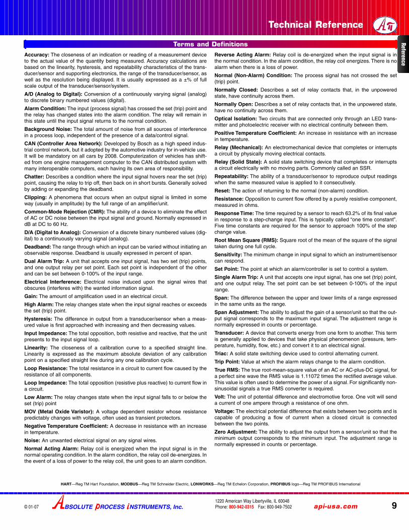
Accuracy: The closeness of an indication or reading of a measurement deviceto the actual value of the quantity being measured. Accuracy calculations arebased on the linearity, hysteresis, and repeatability characteristics of the trans-ducer/sensor and supporting electronics, the range of the transducer/sensor, aswell as the resolution being displayed. It is usually expressed as a ±% of fullscale output of the transducer/sensor/system.
A/D (Analog to Digital): Conversion of a continuously varying signal (analog)to discrete binary numbered values (digital).
Alarm Condition: The input (process signal) has crossed the set (trip) point andthe relay has changed states into the alarm condition. The relay will remain inthis state until the input signal returns to the normal condition.
Background Noise: The total amount of noise from all sources of interferencein a process loop, independent of the presence of a data/control signal.
CAN (Controller Area Network): Developed by Bosch as a high speed indus-trial control network, but it adopted by the automotive industry for in-vehicle use.It will be mandatory on all cars by 2008. Computerization of vehicles has shift-ed from one engine management computer to the CAN distributed system withmany interoperable computers, each having its own area of responsibility.
Chatter: Describes a condition where the input signal hovers near the set (trip)point, causing the relay to trip off, then back on in short bursts. Generally solvedby adding or expanding the deadband.
Clipping: A phenomena that occurs when an output signal is limited in someway (usually in amplitude) by the full range of an amplifier/unit.
Common-Mode Rejection (CMR): The ability of a device to eliminate the effectof AC or DC noise between the input signal and ground. Normally expressed indB at DC to 60 Hz.
D/A (Digital to Analog): Conversion of a discrete binary numbered values (dig-ital) to a continuously varying signal (analog).
Deadband: The range through which an input can be varied without initiating anobservable response. Deadband is usually expressed in percent of span.
Dual Alarm Trip: A unit that accepts one input signal, has two set (trip) points,and one output relay per set point. Each set point is independent of the otherand can be set between 0-100% of the input range.
Electrical Interference: Electrical noise induced upon the signal wires thatobscures (interferes with) the wanted information signal.
Gain: The amount of amplification used in an electrical circuit.
High Alarm: The relay changes state when the input signal reaches or exceedsthe set (trip) point.
Hysteresis: The difference in output from a transducer/sensor when a meas-ured value is first approached with increasing and then decreasing values.
Input Impedance: The total opposition, both resistive and reactive, that the unitpresents to the input signal loop.
Linearity: The closeness of a calibration curve to a specified straight line.Linearity is expressed as the maximum absolute deviation of any calibrationpoint on a specified straight line during any one calibration cycle.
Loop Resistance: The total resistance in a circuit to current flow caused by theresistance of all components.
Loop Impedance: The total opposition (resistive plus reactive) to current flow ina circuit.
Low Alarm: The relay changes state when the input signal falls to or below theset (trip) point
MOV (Metal Oxide Varistor): A voltage dependent resistor whose resistancepredictably changes with voltage, often used as transient protectors.
Negative Temperature Coefficient: A decrease in resistance with an increasein temperature.
Noise: An unwanted electrical signal on any signal wires.
Normal Acting Alarm: Relay coil is energized when the input signal is in thenormal operating condition. In the alarm condition, the relay coil de-energizes. Inthe event of a loss of power to the relay coil, the unit goes to an alarm condition.
Reverse Acting Alarm: Relay coil is de-energized when the input signal is inthe normal condition. In the alarm condition, the relay coil energizes. There is noalarm when there is a loss of power.
Normal (Non-Alarm) Condition: The process signal has not crossed the set(trip) point.
Normally Closed: Describes a set of relay contacts that, in the unpoweredstate, have continuity across them.
Normally Open: Describes a set of relay contacts that, in the unpowered state,have no continuity across them.
Optical Isolation: Two circuits that are connected only through an LED trans-mitter and photoelectric receiver with no electrical continuity between them.
Positive Temperature Coefficient: An increase in resistance with an increasein temperature.
Relay (Mechanical): An electromechanical device that completes or interruptsa circuit by physically moving electrical contacts.
Relay (Solid State): A solid state switching device that completes or interruptsa circuit electrically with no moving parts. Commonly called an SSR.
Repeatability: The ability of a transducer/sensor to reproduce output readingswhen the same measured value is applied to it consecutively.
Reset: The action of returning to the normal (non-alarm) condition.
Resistance: Opposition to current flow offered by a purely resistive component,measured in ohms.
Response Time: The time required by a sensor to reach 63.2% of its final valuein response to a step-change input. This is typically called “one time constant”.Five time constants are required for the sensor to approach 100% of the stepchange value.
Root Mean Square (RMS): Square root of the mean of the square of the signaltaken during one full cycle.
Sensitivity: The minimum change in input signal to which an instrument/sensorcan respond.
Set Point: The point at which an alarm/controller is set to control a system.
Single Alarm Trip: A unit that accepts one input signal, has one set (trip) point,and one output relay. The set point can be set between 0-100% of the inputrange.
Span: The difference between the upper and lower limits of a range expressedin the same units as the range.
Span Adjustment: The ability to adjust the gain of a sensor/unit so that the out-put signal corresponds to the maximum input signal. The adjustment range isnormally expressed in counts or percentage.
Transducer: A device that converts energy from one form to another. This termis generally applied to devices that take physical phenomenon (pressure, tem-perature, humidity, flow, etc.) and convert it to an electrical signal.
Triac: A solid state switching device used to control alternating current.
Trip Point: Value at which the alarm relays change to the alarm condition.
True RMS: The true root-mean-square value of an AC or AC-plus-DC signal, fora perfect sine wave the RMS value is 1.11072 times the rectified average value.This value is often used to determine the power of a signal. For significantly non-sinusoidal signals a true RMS converter is required.
Volt: The unit of potential difference and electromotive force. One volt will senda current of one ampere through a resistance of one ohm.
Voltage: The electrical potential difference that exists between two points and iscapable of producing a flow of current when a closed circuit is connectedbetween the two points.
Zero Adjustment: The ability to adjust the output from a sensor/unit so that theminimum output corresponds to the minimum input. The adjustment range isnormally expressed in counts or percentage.
Terms and Definitions Reference
HART—Reg TM Hart Foundation, MODBUS—Reg TM Schneider Electric, LONWORKS—Reg TM Echelon Corporation, PROFIBUS logo—Reg TM PROFIBUS International

10
Technical Reference
© 01-07
E = I x ROHM'S LAW is the relationship between current, voltage and resistance. Itstates that current varies directly with voltage and inversely with resistance.
E (Electromotive Force or Voltage) is the electrical potential that existsbetween two points and is capable of producing a flow of current when a closedcircuit is connected between the two points. The unit of measure for voltage isthe volt (V). One volt will send one ampere of current through a resistance ofone ohm.
I (current) is the flow of electrons past a point in a specified period of time, usu-ally one second. The unit of measure for current is the ampere (A). One ampereof current is 6.24 x 10¹⁸ electrons passing a point in one second. Ampere is oftenshortened to amp.
R (resistance) is the opposition to current flow offered by a resistive compo-nent. The unit of measure for resistance is the ohm. One ohm is the resistancethrough which a current of one ampere will flow when a voltage of one volt isapplied.
From To FormulaFahrenheit Celsius °C = (°F – 32) / 1.8Fahrenheit kelvin K = (°F + 459.67) / 1.8Fahrenheit Rankine °Ra = °F + 459.67Fahrenheit Réaumur °R = (°F – 32) / 2.25
Celsius Fahrenheit °F = °C × 1.8 + 32Celsius kelvin K = °C + 273.15Celsius Rankine °Ra = °C × 1.8 + 32 + 459.67Celsius Réaumur °R = °C × 0.8
kelvin Celsius °C = K – 273.15 kelvin Fahrenheit °F = K × 1.8 – 459.67kelvin Rankine °Ra = K × 1.8kelvin Réaumur °R = (K – 273.15) × 0.8
Rankine Celsius °C = (°Ra – 32 – 459.67) / 1.8Rankine Fahrenheit °F = °Ra – 459.67 Rankine kelvin K = °Ra / 1.8Rankine Réaumur °R = (°Ra – 459.67 – 32) / 2.25
Réaumur Celsius °C = °R × 1.25Réaumur Fahrenheit °F = °R × 2.25 + 32Réaumur kelvin K = °R × 1.25 + 273.15Réaumur Rankine °Ra = °R × 2.25 + 32 + 459.67
The Celsius scale (°C), sometimes referred to as the “centigrade” scale, wasdevised by Swedish astronomer Andres Celsius (1701-1744) for scientific pur-poses. It has 100 degrees between the freezing point of 0°C and boiling point of100 °C of pure water at a standard air pressure of 29.92 inches of mercury. Theterm Celsius was adopted in 1948 by an international conference on weightsand measures to replace the term centigrade. This is the most widely used tem-perature scale in the world.
The Fahrenheit scale (°F) is used primarily in the United States. The freezingpoint of water is 32°F and the boiling point is 212°F while measured at a stan-dard air pressure of 29.92 inches of mercury. 0°F was the coldest temperatureDr. Gabriel Daniel Fahrenheit (1686-1736) could create with a mixture of ice andsalt. He is credited with the invention of the mercury thermometer introducing itand the °F scale in 1714. His thermometer was based on a design by Galileo.
The absolute or kelvin (K) scale is used primarily for scientific work. It wasinvented by William Thomson, also know as Lord Kelvin. The hypothetical tem-perature characterized by a complete absence of heat energy and the point atwhich molecular motion would theoretically stop is –273.15°C or “absolutezero”. The kelvin scale uses this number as 0 K with divisions being the sameas the Celsius scale. Temperatures on this scale are called kelvins, thus thedegree symbol is not used with the capital “K” symbol, nor is the word kelvincapitalized when referring to the temperature units.
The Réaumur scale was created by R A F de Réaumur (1683-1757). He usedthe freezing point of water as 0°Re and the boiling point at 80°Re. It was usedin the 18th and 19th centuries mainly in France for scientific work, but is stillused today by some European wine and cheese makers.
W J M Rankine (1820-1872) created this scale, which was merely the kelvinscale using the Fahrenheit degree instead of the Celsius. It has been used insome scientific and thermodynamics work but is not commonly used today.
Resistance may vary ±10% or more depending on impurities, alloys, coatings, state of annealing, etc. Always check wire manufacturer’s specifications.
Voltage (Volts) Resistance
(Ohm
s)
E R
Pow
er
(Watts) Current (Am
ps)
IP
E x IE2
R
ER P
E
PR
E2
P
EIP
I2
PI
I x R
I2 x R
P x R
Ohms per 1000 ftAWG Dia. in. Dia. mm 0°C 20°C 50°C
10 0.1019 2.588 0.92 Ω 0.99 Ω 1.12 Ω12 0.0808 2.052 1.46 Ω 1.59 Ω 1.78 Ω14 0.0641 1.628 2.33 Ω 2.53 Ω 2.82 Ω16 0.0508 1.290 3.70 Ω 4.02 Ω 4.49 Ω18 0.0403 1.023 5.88 Ω 6.39 Ω 7.14 Ω20 0.0320 0.812 9.36 Ω 10.15 Ω 11.35 Ω
Ohms per 1000 ftAWG Dia. in. Dia mm 0°C 20°C 50°C
22 0.0254 0.6451 14.87 Ω 16.14 Ω 18.05 Ω24 0.0201 0.5105 23.65 Ω 25.67 Ω 28.70 Ω26 0.0159 0.4038 37.61 Ω 40.81 Ω 45.63 Ω28 0.0126 0.3200 59.80 Ω 64.90 Ω 72.55 Ω30 0.0100 0.2540 95.10 Ω 103.20 Ω 115.40 Ω32 0.0080 0.2032 151.20 Ω 164.10 Ω 183.40 Ω
Ohm’s Law
Typical Solid Copper Wire Resistance
Temperature Conversion and Information
BSOLUTE ROCESS NSTRUMENTS, Inc.1220 American Way Libertyville, IL 60048Phone: 800-942-0315 Fax: 800-949-7502
For latest product information or to contact yourlocal representative visit api-usa.com
Refe
renc
e
Technical Reference
BSOLUTE ROCESS NSTRUMENTS, Inc. api-usa.com 111220 American Way Libertyville, IL 60048Phone: 800-942-0315 Fax: 800-949-7502© 01-07
1. Do you recommend protecting the module’s 115 VAC power input witha fuse?It is not required, but a ½ Amp Fast Blow fuse can be used for each module.
2. We are using many different types of your signal conditioners and wishto protect the inputs and outputs from short circuits and over voltage.How can we achieve this?Applying a short circuit to any of the signal input terminals will not affect themodules. Exposing the signal input to high voltage will damage the unit butusing a zener diode, due to its resistance value, will cause the input range toneed recalibrating. Try a Varistor or TransZorb®. Do NOT under any circum-stances short circuit the signal output, the unit can be damaged.
3. Which direction do we turn the deadband potentiometer screw to givethe minimum and the maximum deadband?For the minimum amount (1%), turn the potentiometer screw CCW, counter-clockwise. For the maximum amount (100%), turn the potentiometer screwCW, clockwise.
4. We have a 4-20 mA input and require 4 set points at the output. Do youhave a product for this?Yes, you can connect 2 of our API 1020 G units in series in the 4-20 mA inputloop since the input impedance for current is 50 Ω and the drop is very low.
5. We are running a 4-20 mA signal between a chart recorder and a DCSover a distance of 5000 feet (10,000 total loop). Can we use your isola-tor signal conditioner for this? Yes, however you must select the proper gauge wire to reduce the imped-ance of the system
total load = impedance of the instrument + impedance of the wireFor a 4-20 mA loop, our compliance voltage is 20 V which allows a total of1000 Ω load. Also, to prevent problems from noise, it is recommended thatyou use shielded, twisted pair wires.
6. For modules with a 4-20 mA output signal, what are the minimum andmaximum output load resistance?For the units with a 20 V compliance, the output range is 10 to 1000 ohms.For the units with a 12 V compliance, the output range is 10 to 600 ohms.
7. For the DC output models, what are the output impedances in the volt-age and current mode?The DC outputs are FET driven and are active outputs that change depend-ing on the mode and range.
DC output with 12 V ComplianceCURRENT Mode VOLTAGE Modeless than 600 ohms greater than 1000 ohms
DC output with 20 V ComplianceCURRENT Mode VOLTAGE Modeless than 1000 ohms greater than 1000 ohms
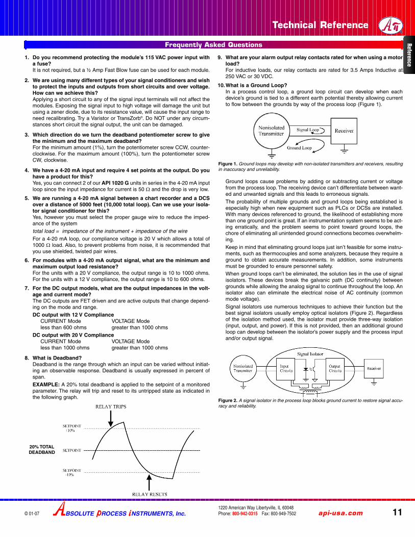
8. What is Deadband?Deadband is the range through which an input can be varied without initiat-ing an observable response. Deadband is usually expressed in percent ofspan.
EXAMPLE: A 20% total deadband is applied to the setpoint of a monitoredparameter. The relay will trip and reset to its untripped state as indicated inthe following graph.
9. What are your alarm output relay contacts rated for when using a motorload?For inductive loads, our relay contacts are rated for 3.5 Amps Inductive at250 VAC or 30 VDC.
10.What is a Ground Loop?In a process control loop, a ground loop circuit can develop when eachdevice’s ground is tied to a different earth potential thereby allowing currentto flow between the grounds by way of the process loop (Figure 1).
Ground loops cause problems by adding or subtracting current or voltagefrom the process loop. The receiving device can’t differentiate between want-ed and unwanted signals and this leads to erroneous signals.
The probability of multiple grounds and ground loops being established isespecially high when new equipment such as PLCs or DCSs are installed.With many devices referenced to ground, the likelihood of establishing morethan one ground point is great. If an instrumentation system seems to be act-ing erratically, and the problem seems to point toward ground loops, thechore of eliminating all unintended ground connections becomes overwhelm-ing.
Keep in mind that eliminating ground loops just isn’t feasible for some instru-ments, such as thermocouples and some analyzers, because they require aground to obtain accurate measurements. In addition, some instrumentsmust be grounded to ensure personnel safety.
When ground loops can’t be eliminated, the solution lies in the use of signalisolators. These devices break the galvanic path (DC continuity) betweengrounds while allowing the analog signal to continue throughout the loop. Anisolator also can eliminate the electrical noise of AC continuity (commonmode voltage).
Signal isolators use numerous techniques to achieve their function but thebest signal isolators usually employ optical isolators (Figure 2). Regardlessof the isolation method used, the isolator must provide three-way isolation(input, output, and power). If this is not provided, then an additional groundloop can develop between the isolator’s power supply and the process inputand/or output signal.
20% TOTALDEADBAND
Figure 2. A signal isolator in the process loop blocks ground current to restore signal accu-racy and reliability.
Figure 1. Ground loops may develop with non-isolated transmitters and receivers, resultingin inaccuracy and unreliability.
Frequently Asked Questions Reference

12
Technical Reference
© 01-07
Electrical interference, or noise, is an unwanted electrical signal that can causeintolerable error in, or complete disablement of an electronic control or measure-ment systems. Interference or electrical noise is broken down into two somewhatoverlapping categories:
Radio Frequency Interference (RFI)
Electromagnetic Interference (EMI).
The effects of Radio Frequency Interference (RFI) and ElectromagneticInterference (EMI) can cause unpredictable and non-repeatable degradation ofinstrument performance and accuracy, and even complete instrument failure.This can result in reduced process efficiency and production, plant shutdowns,and sometimes dangerous safety hazards.
There are two basic approaches to protecting and electronic system from theharmful effects of radio frequency and electromagnetic interference. The first isto keep the interference from entering the system or instrument using specialshielding, designs and terminal filters. The second is to design the system orinstruments circuitry so that it is inherently immune to RFI/EMI.
Some of the more commonly encountered sources of interference are:
❑ Radio, television and hand-held transmitters (walkie-talkies)
❑ Cellular telephones
❑ Fluorescent lights
❑ Radar
❑ Weather related electrical discharges such as lightning
❑ Static discharges
❑ Induction heating systems
❑ High speed power switching elements such as SCRs and thyristors
❑ High AC current conductors
❑ Large solenoids or relays
❑ Transformers
❑ AC or DC motors
❑ Ultrasonic cleaning or ultrasonic welding equipment
❑ Welding equipment
❑ Vehicle ignition systems
When using Api alarm module relays to switch inductive loads, maximum relaylife and transient EMI suppression is achieved by using external protection. Allexternal protection devices should be placed directly across the load and allleads lengths should be kept to a minimum length.
For AC inductive loads (see Figure 1), place a properly rated MOV across theload in parallel with a series RC snubber. A good RC snubber consists of a 0.1
µF polypropylene capacitor of sufficient voltage and a 47 ohm ½ Watt carbonfilm resistor.
For DC inductive loads (see Figure 2), place a diode across the load (1N4006recommended) being sure to observe proper polarity. Use of an RC snubber isan optional enhancement.
Figure 1: AC inductive loads. Figure 2: DC inductive loads.
Relay Protection and EMI Suppression
RFI and EMI
While there are many different types of signal conditioners, their basic functionis to change or alter signals so that different process devices can communicatewith each other accurately. Signal conditioners are most commonly needed tolink temperature, pressure, weighing, level, and flow devices with indicators,recorders, and computerized process monitoring and control systems. Signalconditioners can also perform some other tasks for you as listed below.
SIGNAL CONVERSIONA signal conditioner can change an analog signal from one form to anotherallowing equipment with dissimilar signals to communicate. For instance, if apiece of field equipment puts out a 4-20 mA signal and the control system needsa ±10 V input signal, the signal from the field equipment must be converted. Asignal conditioner that accepts a 4-20 mA input and produces a ±10 V outputsolves the problem.
SIGNAL BOOSTINGThe signal conditioner increases load drive capability in the loop allowing instal-lation of additional instruments. This works because the input impedance ofmost isolators is much less the load drive capability of a loop. Therefore addingan isolator to the loop boosts the loop’s net load drive capability. This is espe-cially useful when it becomes necessary to add additional devices to an existingoverloaded loop.
SIGNAL ALARMINGWarns of trouble if a process signal reaches a too high or too low level. A signalconditioner that accepts an analog signal (4-20 mA, 1-5 V, etc.) and produces arelay output is an inexpensive way of providing a redundant safety device in theevent of a system failure.
SIGNAL ISOLATIONStops ground loops from affecting the accuracy of a process signal. Groundloops are a common complaint at system startup and can be eliminated byinstalling isolated signal conditioners, or isolators, on the process loop betweena non-isolated device and a control system.
SPECIFYINGA signal conditioner requires much of the same information as specifying anyother instrument. Always consider these elements:
❑ Power Source
❑ Input Signal
❑ Output Signal
❑ Desired Options
Signal Conditioners
BSOLUTE ROCESS NSTRUMENTS, Inc.1220 American Way Libertyville, IL 60048Phone: 800-942-0315 Fax: 800-949-7502
For latest product information or to contact yourlocal representative visit api-usa.com
Refe
renc
e

Technical Reference
BSOLUTE ROCESS NSTRUMENTS, Inc. api-usa.com 131220 American Way Libertyville, IL 60048Phone: 800-942-0315 Fax: 800-949-7502© 01-07
Active Power (Watt): Sometime called Real Power, True Power or Effectivepower. It describes the actual amount of power present in a system in watts (W)and the symbol is P. In a simple resistive circuit, the voltage and current are inphase and the active power is equal to the apparent power.
Ambient Temperature: The temperature of the air, water, or surrounding earth.
Ampacity: The current-carrying capacity of conductors or equipment,expressed in amperes.
Ampere (A) or amp: The basic SI unit measuring the quantity of electricity. Theunit for electric current or the flow of electrons. One amp is 1 coulomb passingin one second. One amp is produced by an electric force of 1 volt acting acrossa resistance of 1 ohm.
Ampere-hour (Ah): Quantity of electricity or measure of charge. (1 Ah = 3600Coulomb)
Apparent power (VA): Used to describe the useful or working power in a sys-tem. It is measured in VA volt-amperes (not watts). The symbol is S. It is used todescribe the resultant power due to the phase separation between the voltageand current. In an alternating current circuit, both the current and voltage aresinusoidal. The Apparent Power is the useful power in the system by taking intoaccount the Power Factor.
Ground: A large conducting body (such as the earth) used as a common returnfor an electric circuit and as an arbitrary zero of potential.
Impedance: The total opposition that a circuit offers to the flow of alternatingcurrent or any other varying current at a particular frequency.
Inductive reactance: Electrical current produces heat and/or a magnetic field(such as in the windings of a motor). The tendency for current flow and changesin flow to be influenced by magnetic fields is inductance. An AC circuit that con-tains only inductance, capacitance, or a combination of the two is defined by thetotal opposition to current flow expressed in reactance. Inductance only affectscurrent flow when the current is changing. Inductance produces a self-inducedvoltage (called a counter EMF) that opposes changes in current. Obviously, thecurrent changes constantly in an AC circuit. Inductance in an AC circuit, there-fore causes a continual opposition to current flow is called inductive reactance.
Power Factor (PF): Power factor is the ratio of the Active Power to the ApparentPower factor. It is a number between 0 and 1 and is used to determine how effi-cient a power system is. It is determined by the type of loads connected to thepower system. For a purely resistive load, the power factor will be 1, and onlyreal power will flow. Inductive loads such as transformers and motors absorbreactive power. Capacitive loads such as capacitor banks or long cables gener-ate reactive power.
Reactive Power (VAR): Reactive power is described as the amount of powerrequired to overcome the phase shift between the current and voltage due toinductive and capacitive effects. It is measured in reactive volt-ampere's (VAr)and the symbol is Q. It is desirable to keep Reactive Power to a minimum.
Kilowatt-hour (kWh): One thousand watts acting over a period of 1 hour. ThekWh is a unit of energy. 1 kWh=3600 kJ.
Ohm: The derived SI unit for electrical resistance or impedance; one ohmequals one volt per ampere.
Total harmonic distortion (THD): The measure of closeness in shape betweena waveform and its fundamental component.
Volt (V): A unit of measure of the force given the electrons in an electric circuit.One volt produces one ampere of current when acting on a resistance of oneohm.
Voltage Drop: The loss of voltage between the input to a device and the outputfrom a device due to the internal impedance or resistance of the device. In allelectrical systems, the conductors should be sized so that the voltage dropnever exceeds 3% for power, heating, and lighting loads or combinations ofthese. Furthermore, the maximum total voltage drop for conductors for feedersand branch circuits combined should never exceed 5%.
Watt (W): The unit of electric power, or amount of work (J), done in a unit of time.One ampere of current flowing at a potential of one volt produces one watt ofpower.
Watt-hour (Wh): One watt acting over a period of 1 hour. The Wh is a unit ofenergy. 1 Wh=3.600 kJ.
Electrical Power Terminology
Reference
When connecting analog current (such as 4-20 mA) signals to a PLC, data acquisi-tion system or measuring instrument, you can often choose between single-ended ordifferential inputs. When using transmitters and signal conditioners you must choosebetween sinking or sourcing I/O. What is the difference between these and whichshould you use?
It is important to keep three things in mind:
POWER Which device is providing power to the loop?
SIGNAL What is the signal path? It must be connected correctly and be the righttype of signal for the circuit to operate.
GROUND Where are the ground connections? Is there a potential for a ground loop?
An Api signal conditioner can provide solutions to the above issues. It can power aloop, or be passive, convert incompatible signals and provide isolation to breakground loops.
Single-Ended InputsTypically used with a two-wire transmitter, one wire is connected to a power sourceand the other wires from each signal source are connected to the PLC or receivingdevice. This assumes the sensor ground and the PLC or measuring device groundhave the same value. In reality, earth ground can vary in different locations. Thesepotential differences create current paths or ground loops leading to measurementerrors.The errors generally increase as distance between earth grounds increase andwith the presence of other electrical equipment in the vicinity.
Single ended inputs are also susceptible to radiated electrical noise, since the singlewires pick up stray EMI and superimpose it on the signal.
Differential InputsTwo signal wires run from each signal source to the PLC or receiving device. Onegoes to the + input and one to the – input. This allows the PLC or receiving device tomeasure each of the wires in reference to its own ground, eliminating grounding dif-ferential errors. Noise immunity is improved since the pair of wires pick up interferenceequally.
When using differential inputs, the sensor may “float” or have no ground connection.It may be preferable to connect the negative (–) signal wire to the PLC terminalmarked 0V, REF or GND.
Sink vs. SourceWhen connecting various current inputs and outputs it is important to keep in mindwhat device is powering the circuit. Inputs and outputs can either “sink” current or“source” current. A 2-wire transmitter is a passive device and thus “sinks” current. A4-wire transmitter operates on an external power source and thus “sources” or pro-vides power to the circuit.
Sinking Input The device receiving the signal does not provide power. It actsas a resistive load It must be connected to device that sourcesits output signal, or a to sinking output with a loop power supplyin the circuit.
Sourcing Input The device receiving the signal provides power for the input sig-nal. It must be connected to sinking output, such as a 2-wiretransmitter which uses the power from the receiving device.
Sinking Output The device’s output signal does not provide power. It must beconnected to a device that provides power for the output signal,or a sinking input with a loop power supply in the circuit.
Sourcing Output The device’s output signal powers the output circuit. It must beconnected to a receiving device that provides no power andacts as a resistive load, such as a 2-wire passive transmitter
Note that sinking-sourcing and sourcing-sinking pairing is always used, and neversourcing-sourcing or sinking-sinking.
EXTSUP (External Supply) OptionThe Api EXTSUP option provides a sinking or unpowered signal conditioner currentoutput. It is required due to the fact that PLC analog input cards can either be config-ured to accept differential (individual common) inputs or single-ended (one common)inputs.
A PLC often has an input power supply, or one installed in the panel, as the powersource for the inputs. Due to differences in ground potential between differential inputsand single-ended inputs, they cannot be intermixed on the same PLC analog inputcard. Doing so may cause input signal errors or possible PLC shutdown. Use of theEXTSUP option is required to provide a sinking output for the signal conditioner to becompatible with the PLC’s single ended inputs.
Single Ended vs. Differential, Sink vs. Source, EXTSUP Option

14
Technical Reference
FREE APPLICATION ASSISTANCECall Customer Service
800-942-0315
© 01-07
API Standard Features
API Bi-Color Alarm LEDsThe API alarm family provides alarm status indication via a bi-color LED foreach setpoint. The LED indicates green for a non-alarm condition and red foran alarm condition whether or not the unit is configured for normal acting orreverse acting.
API Dual Alarm Trip
GreenNo Alarm
C Common NC Normally Closed
NO Normally Open
API LoopTracker Diagnostic Tool
API Functional Test Pushbutton
Transmitter Output TestThe Functional Test Pushbutton will, when pressed, output a test signal inde-pendent of the input signal. This signal is adjustable from 0-100% of span byholding the Test button down and adjusting the Test potentiometer on the unit.On some models the test signal is fixed at 50% of output span.
This feature allows the technician to temporarily inject a test or preset calibra-tion signal into the output loop without manipulating the input signal. This signalcan be used to check loop status, downstream display operation, downstreamalarm operation, etc.
Alarm Function TestPressing the Functional Test Pushbutton will switch the relay(s) and bi-colorLED(s) to the opposite state regardless of the input signal level. When released,the module will return to its normal operating state.
With the latching alarm mode or option, pressing the Test button allows thelatched alarm to be reset, provided the alarm condition no longer exists for thatsetpoint.
The functional test button not only allows the technician to test the relays, butalso the operation of the device the relays are controlling. For example, an API1000 G is used as a high level alarm to prevent the overflow of a wastewatertank. The relay is wired to a pump which, when a high level is detected, turns onand pumps the wastewater to an overflow tank. Since over-filling the tank to testthe pump is impractical, the technician simply has to depress the Test buttonand check the operation of the pump.
Energized
When the process signal crosses the setpoint, the LED will indicate red for analarm condition. The relay coil de-energizes and the “C” and “NC” contacts havecontinuity.
Should the alarm lose power in the normal acting mode, the coil will de-ener-gize and go to an alarm condition.
REDAlarm NC Normally Closed
NO Normally OpenOff
C Common
OFFPower Off NC Normally Closed
NO Normally OpenOff
C Common
Reverse Acting Relay Operation
When the process signal crosses the setpoint, the LED will indicate red for analarm condition. The coil energizes and the “C” & “NO” contacts have continuity.
Should the alarm lose power in the reverse mode the coil will de-energize andfail to a non-alarm condition.
GreenNo Alarm
C Common NC Normally Closed
NO Normally OpenOff
C Common NC Normally Closed
NO Normally OpenEnergized
REDAlarm
C Common NC Normally Closed
NO Normally OpenOff
OFFPower Off
In the normal (fail-safe) mode the LED will indicate green for a non-alarm con-dition. The relay coil is energized and the “C” & “NO” contacts have continuity.
In the reverse acting mode of operation the LED will indicate green for a non-alarm condition. The relay coil is de-energized and the “C” and “NC” contactshave continuity.
Off 4 mA 20 mA
The API LoopTracker LEDs indicate the level of the input and/or output signal byvarying its intensity. As the process signal increases, the brightness of the LEDincreases, and as the signal decreases the LED brightness decreases.
Should a problem develop in the loop, such as a faulty device in the loop caus-ing an incomplete path for current, the LoopTracker detects this and ceases toilluminate. This function works on both the input and output loop allowing thetechnician to diagnose the cause of the problem quickly and efficiently thereforeminimizing system down time.
Input LoopTracker® LED
Bi-Color Alarm 2 LED
Bi-Color Alarm 1 LED
Functional Test Pushbutton
API Transmitter
Functional Test Pushbutton
Input LoopTracker® LED
Output LoopTracker LED
Normal Acting Relay Operation
Off 4 mA 20 mA
Input LoopTracker® LED
Output LoopTracker LED
BSOLUTE ROCESS NSTRUMENTS, Inc.1220 American Way Libertyville, IL 60048Phone: 800-942-0315 Fax: 800-949-7502
For latest product information or to contact yourlocal representative visit api-usa.com
Refe
renc
e
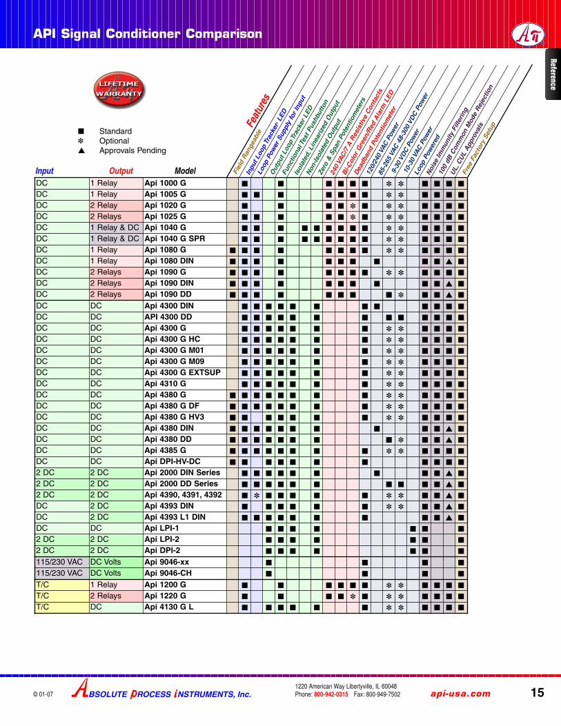
API Signal Conditioner Comparison
BSOLUTE ROCESS NSTRUMENTS, Inc. api-usa.com 151220 American Way Libertyville, IL 60048Phone: 800-942-0315 Fax: 800-949-7502© 01-07
Feat
ures
Inpu
t Loo
p Tr
acke
r®LE
D
Out
put L
oop
Trac
ker
LED
Bi-C
olor
Gre
en/R
ed A
larm
LED
Isol
ated
, Lin
eariz
ed O
utpu
t
Non
-Isol
ated
Out
put
240
VAC
/7 A
Res
istiv
e C
onta
cts
120/
240
VAC
Pow
er
85-2
65 V
AC 4
8-30
0 VD
C P
ower
9-30
VD
C P
ower
10-3
0 VA
C P
ower
Loop
Pow
ered
Loop
Pow
er S
uppl
y fo
r In
put
Func
tiona
l Tes
t Pus
hbut
ton
Dea
dban
d Po
tent
iom
eter
Noi
se Im
mun
ity F
ilter
ing
100
dB C
omm
on M
ode
Rej
ectio
n
Fiel
d R
ange
able
UL,
CU
L A
ppro
vals
Free
Fac
tory
Set
up
Zero
& S
pan
Pote
ntio
met
ers
Input Output Model
■ Standard✽ Optional▲ Approvals Pending
DC 1 Relay Api 1000 G ■ ■ ■ ■ ■ ■ ✽ ✽ ■ ■ ■ ■
DC 1 Relay Api 1005 G ■ ■ ■ ■ ■ ■ ■ ✽ ✽ ■ ■ ■ ■
DC 2 Relay Api 1020 G ■ ■ ■ ■ ✽ ■ ✽ ✽ ■ ■ ■ ■
DC 2 Relays Api 1025 G ■ ■ ■ ■ ■ ✽ ■ ✽ ✽ ■ ■ ■ ■
DC 1 Relay & DC Api 1040 G ■ ■ ■ ■ ■ ■ ■ ■ ■ ✽ ✽ ■ ■ ■ ■
DC 1 Relay & DC Api 1040 G SPR ■ ■ ■ ■ ■ ■ ■ ■ ■ ✽ ✽ ■ ■ ■ ■
DC 1 Relay Api 1080 G ■ ■ ■ ■ ■ ■ ■ ■ ✽ ✽ ■ ■ ■ ■
DC 1 Relay Api 1080 DIN ■ ■ ■ ■ ■ ■ ■ ■ ■ ■ ▲ ■
DC 2 Relays Api 1090 G ■ ■ ■ ■ ■ ■ ■ ■ ✽ ✽ ■ ■ ■ ■
DC 2 Relays Api 1090 DIN ■ ■ ■ ■ ■ ■ ■ ■ ■ ■ ▲ ■
DC 2 Relays Api 1090 DD ■ ■ ■ ■ ■ ■ ■ ■ ✽ ■ ■ ▲ ■
DC DC Api 4300 DIN ■ ■ ■ ■ ■ ■ ■ ■ ■ ■ ■ ■
DC DC API 4300 DD ■ ■ ■ ■ ■ ■ ■ ■ ■ ■ ■ ■ ■
DC DC Api 4300 G ■ ■ ■ ■ ■ ■ ■ ✽ ✽ ■ ■ ■ ■
DC DC Api 4300 G HC ■ ■ ■ ■ ■ ■ ■ ✽ ✽ ■ ■ ■ ■
DC DC Api 4300 G M01 ■ ■ ■ ■ ■ ■ ■ ✽ ✽ ■ ■ ■ ■
DC DC Api 4300 G M09 ■ ■ ■ ■ ■ ■ ■ ✽ ✽ ■ ■ ■ ■
DC DC Api 4300 G EXTSUP ■ ■ ■ ■ ■ ■ ■ ✽ ✽ ■ ■ ■ ■
DC DC Api 4310 G ■ ■ ■ ■ ■ ■ ■ ✽ ✽ ■ ■ ■ ■
DC DC Api 4380 G ■ ■ ■ ■ ■ ■ ■ ■ ✽ ✽ ■ ■ ■ ■
DC DC Api 4380 G DF ■ ■ ■ ■ ■ ■ ■ ■ ✽ ✽ ■ ■ ■ ■
DC DC Api 4380 G HV3 ■ ■ ■ ■ ■ ■ ■ ✽ ✽ ■ ■ ■ ■
DC DC Api 4380 DIN ■ ■ ■ ■ ■ ■ ■ ■ ■ ■ ▲ ■
DC DC Api 4380 DD ■ ■ ■ ■ ■ ■ ■ ■ ✽ ■ ■ ▲ ■
DC DC Api 4385 G ■ ■ ■ ■ ■ ■ ■ ■ ✽ ✽ ■ ■ ■ ■
DC DC Api DPI-HV-DC ■ ■ ■ ■ ■ ■ ■ ■ ■ ■ ■
2 DC 2 DC Api 2000 DIN Series ■ ■ ■ ■ ■ ■ ■ ■ ■ ▲ ■
2 DC 2 DC Api 2000 DD Series ■ ■ ■ ■ ■ ■ ■ ■ ■ ■ ▲ ■
2 DC 2 DC Api 4390, 4391, 4392 ■ ✽ ■ ■ ■ ■ ■ ✽ ✽ ■ ■ ▲ ■
DC 2 DC Api 4393 DIN ■ ■ ■ ■ ■ ■ ✽ ✽ ■ ■ ▲ ■
DC 2 DC Api 4393 L1 DIN ■ ■ ■ ■ ■ ■ ■ ■ ■ ▲ ■
DC DC Api LPI-1 ■ ■ ■ ■ ■ ■ ■
2 DC 2 DC Api LPI-2 ■ ■ ■ ■ ■ ■ ■
2 DC 2 DC Api DPI-2 ■ ■ ■ ■ ■ ■ ■
115/230 VAC DC Volts Api 9046-xx ■ ■ ■ ■
115/230 VAC DC Volts Api 9046-CH ■ ■ ■ ■
T/C 1 Relay Api 1200 G ■ ■ ■ ■ ■ ■ ✽ ✽ ■ ■ ■ ■
T/C 2 Relays Api 1220 G ■ ■ ■ ■ ✽ ■ ✽ ✽ ■ ■ ■ ■
T/C DC Api 4130 G L ■ ■ ■ ■ ■ ■ ✽ ✽ ■ ■ ■ ■
Reference

16
Signal Conditioner Comparison API
© 01-07
Feat
ures
Inpu
t Loo
p Tr
acke
r®LE
D
Out
put L
oop
Trac
ker
LED
Bi-C
olor
Gre
en/R
ed A
larm
LED
Isol
ated
Lin
eariz
ed O
utpu
t
Non
-Isol
ated
Out
put
240
VAC
/7 A
Res
istiv
e C
onta
ct
120/
240
VAC
Pow
er
85-2
65 V
AC 4
8-30
0 VD
C P
ower
9-30
VD
C P
ower
10-3
0 VA
C P
ower
Loop
Pow
ered
Loop
Pow
er S
uppl
y fo
r In
put
Func
tiona
l Tes
t Pus
hbut
ton
Dea
dban
d Po
tent
iom
eter
Noi
se Im
mun
ity F
ilter
ing
100
dB C
omm
on M
ode
Rej
ectio
n
Fiel
d R
ange
able
UL,
CU
L A
ppro
vals
Free
Fac
tory
Cal
ibra
tion
Zero
& S
pan
Pote
ntio
met
ers
RTD 1 Relay Api 1400 G ■ ■ ■ ■ ■ ■ ✽ ✽ ■ ■ ■ ■
RTD 2 Relays Api 1420 G ■ ■ ■ ■ ✽ ■ ✽ ✽ ■ ■ ■ ■
RTD DC Api 4001 G L ■ ■ ■ ■ ■ ■ ✽ ✽ ■ ■ ■ ■
Δ RTD DC Api 4001 G SA-B ■ ■ ■ ■ ■ ■ ✽ ✽ ■ ■ ■ ■
Frequency 1 Relay Api 1700 G ■ ✽ ■ ■ ■ ■ ■ ✽ ✽ ■ ■ ■ ■
Frequency 2 Relays Api 1720 G ■ ✽ ■ ■ ■ ✽ ■ ✽ ✽ ■ ■ ■ ■
Frequency DC Api 7010 G ■ ■ ■ ■ ■ ■ ■ ✽ ✽ ■ ■ ■ ■
DC Frequency Api 7500 G ■ ■ ■ ■ ■ ■ ■ ■ ✽ ✽ ■ ■ ■ ■
DC Frequency Api 7500 G M02 ■ ■ ■ ■ ■ ■ ■ ■ ✽ ✽ ■ ■ ■ ■
DC Frequency Api 7500 G SS ■ ■ ■ ■ ■ ■ ■ ■ ✽ ✽ ■ ■ ■ ■
Frequency DC Api 7580 G ■ ■ ■ ■ ■ ■ ■ ■ ✽ ✽ ■ ■ ■ ■
AC 1 Relay Api 1600 G ■ ■ ■ ■ ■ ■ ✽ ✽ ■ ■ ■ ■
AC 2 Relays Api 1620 G ■ ■ ■ ■ ✽ ■ ✽ ✽ ■ ■ ■ ■
AC DC Api 6010 G ■ ■ ■ ■ ■ ■ ✽ ✽ ■ ■ ■ ■
AC DC Api 6010 G 5A ■ ■ ■ ■ ■ ■ ✽ ✽ ■ ■ ■ ■
AC DC Api 6380 G ■ ■ ■ ■ ■ ■ ■ ✽ ✽ ■ ■ ■ ■
AC (RMS) DC Api 6380 G S ■ ■ ■ ■ ■ ■ ■ ✽ ✽ ■ ■ ■ ■
Potentiometer DC Api 4003 G I ■ ■ ■ ■ ■ ■ ✽ ✽ ■ ■ ■ ■
Potentiometer DC Api 4008 G ■ ■ ■ ■ ■ ■ ■ ✽ ✽ ■ ■ ■ ■
Strain Gauge DC Api 4051 G ■ ■ ■ ■ ■ ■ ✽ ✽ ■ ■ ■ ■
Strain Gauge DC Api 4058 G ■ ■ ■ ■ ■ ■ ■ ✽ ✽ ■ ■ ■ ■
Strain Gauge DC Api 4059 G ■ ■ ■ ■ ■ ■ ■ ✽ ✽ ■ ■ ▲ ■
Strain Gauge DC Api 4059 G D ■ ■ ■ ■ ■ ■ ■ ✽ ■ ■ ▲ ■
Strain Gauge DC Api 4059 DIN ■ ■ ■ ■ ■ ■ ■ ✽ ✽ ■ ■ ▲ ■
Strain Gauge DC Api 4059 DD ■ ■ ■ ■ ■ ■ ■ ✽ ■ ■ ▲ ■
Strain Gauge DC Sum Api SUM 025 ■ ■ ■ ■ ■ ■ ■ ✽ ✽ ■ ■ ▲ ■
DC Relay Api 3200 G ■ ■ ■ ■ ■ ■ ■ ■ ✽ ✽ ■ ■ ■ ■
DC Relay Api 3200 G M01 ■ ■ ■ ■ ■ ■ ■ ■ ✽ ✽ ■ ■ ■ ■
DC Relay Api 3200 G M420 ■ ■ ■ ■ ■ ■ ■ ■ ✽ ✽ ■ ■ ■ ■
DC DC Math Api 440X G ■ ■ ■ ■ ■ ■ ✽ ✽ ■ ■ ■ ■
DC DC Sqr. Root Api 4440 G ■ ■ ■ ■ ■ ■ ■ ✽ ✽ ■ ■ ■ ■
InputInput OutputOutput ModelModel
■ Standard✽ Optional▲ Approvals Pending
BSOLUTE ROCESS NSTRUMENTS, Inc.1220 American Way Libertyville, IL 60048Phone: 800-942-0315 Fax: 800-949-7502
For latest product information or to contact yourlocal representative visit api-usa.com
Refe
renc
e