Embed Size (px)
Citation preview
www.absgroup.com
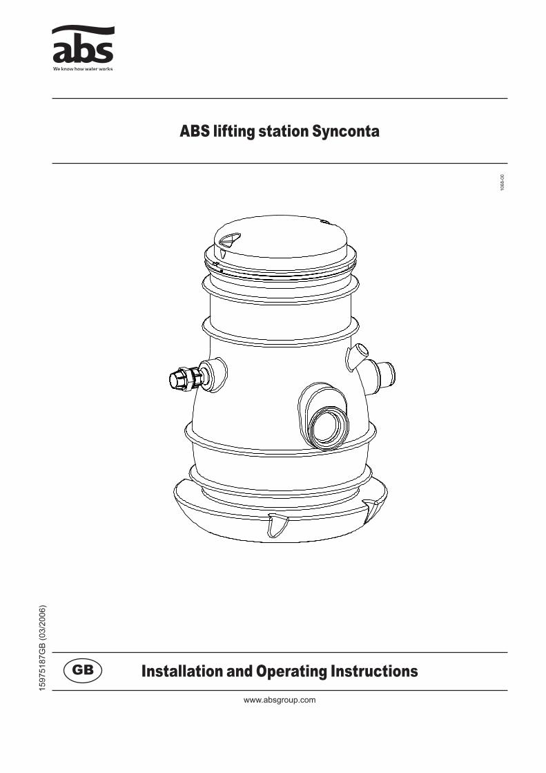
ABS lifting station Synconta
1068
-00
1597
5187
GB
(03/
2006
)
Installation and Operating InstructionsGB
� ������������ ���� ���������� ��������������������������������������������������
ABS lifting station Synconta
ABS reserves the right to alter specifications due to technical developments
C�������1 G������................................................................................................................................................... 3
1.1 Application areas ..................................................................................................................................... 3
1.2 Layout of the Synconta tank and installation example as single pumping station in accordance with EN 12056 for drainage of buildings and sites. .............................................................................................. 3
1.3 ABS high level coupling with discharge pipe pump suspension. (Synconta 901-902 only) .................... 5
1.4 Commentary on the legal DIN EN regulations covering the use of lifting stations for the pumping of effluent containing faecal matter. ............................................................................................................ 5
1.5 Description .............................................................................................................................................. 5
� S�f��y..................................................................................................................................................... 6
3 T��������................................................................................................................................................ 6
4 S��-������������������.......................................................................................................................... 6
4.1 Installation of the collection tank ............................................................................................................. 6
4.2 Opening of the collection tank inlet ports ................................................................................................ 6
4.3 Filling in of the pit .................................................................................................................................... 7
4.4 Discharge Line ........................................................................................................................................ 7
4.5 Level control (Synconta 901 and 902 only) ............................................................................................. 8
4.6 Installation of the control unit .................................................................................................................. 8
5 C�mm����������..................................................................................................................................... 8
6 M����������.......................................................................................................................................... 9
6.1 Commentary on maintenance of lifting stations in accordance with EN 12056 ...................................... 9
6.2 General maintenance hints ..................................................................................................................... 9
ABS��f������������Sy������
601 801 901 901L 902 902L
�������������������������������������� 3
ABS lifting station Synconta
1 G������
1.1 A���������������Synthetic-prefabricated, corrosion resistant sump for ABS submersible pumps designed as single pumping station for automatic pumping of wastewater and sewage in accordance with DIN/EN 12056 from locations and areas below the backwash level.
m These lifting stations may not be used for the collection or pumping of flammable or corrosive liquids. Effluent containing grease, petrol, or oil should only be brought to the lifting station via a separation device.
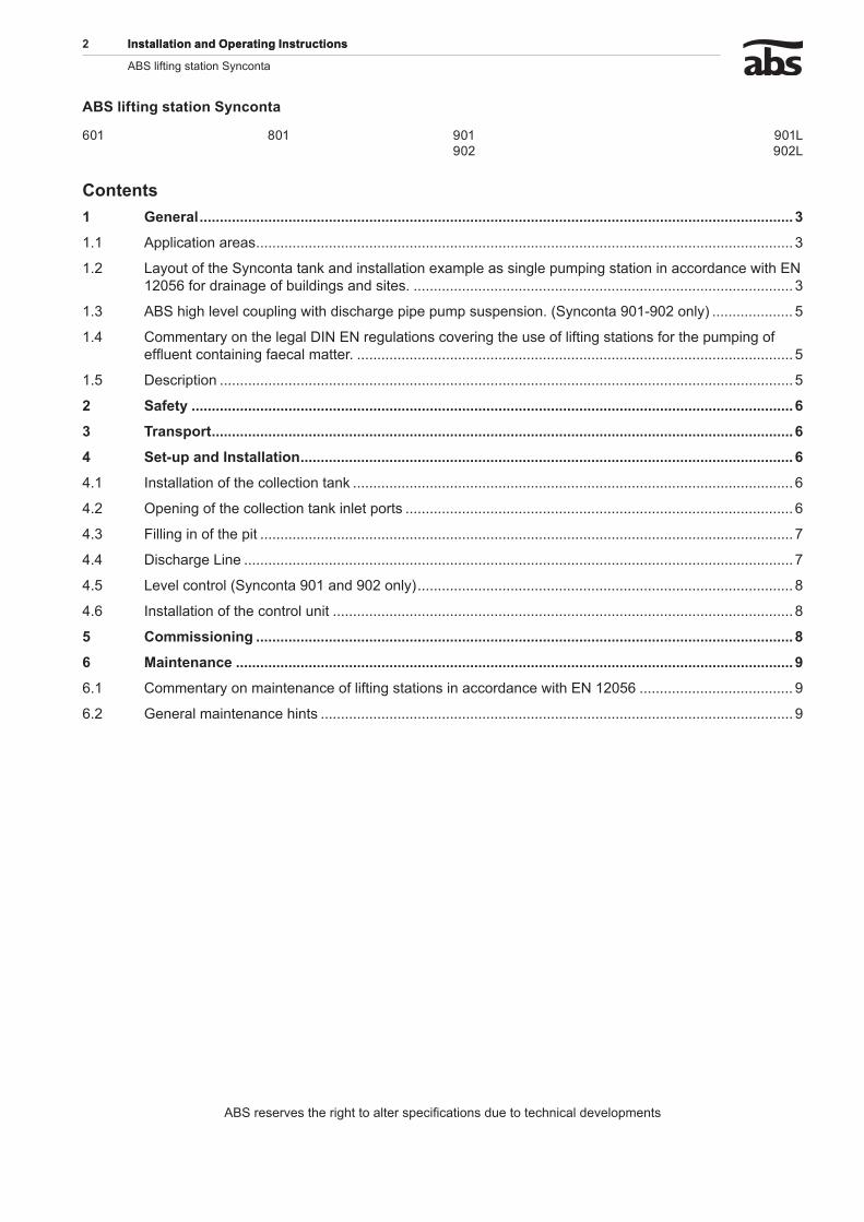
1.� L�y����f�h�Sy���������k�����������������x�m��������������m�������������������������w��hEN1�056f�������������fb�������������������.
1069
-00
Figure 1 Installation example
L�������1 ABS submersible pump2 ABS coupling above water level, self sealing3 Ball check valve 4 Ball shut-off valve5 Measuring device (submerged tube) for pneumatic level control6 Pressure line7 Four inlet pipes DN 1508 Vent/cable pipe DN 100, lead to above roof level9 Cable duct10 ABS control unit, can be chosen with cabinet
ATTENTION TheregulationsofDIN1986/100EN12050and12056shouldbeobserved!
4 ��������������������������������������
ABS lifting station Synconta
1070
-00
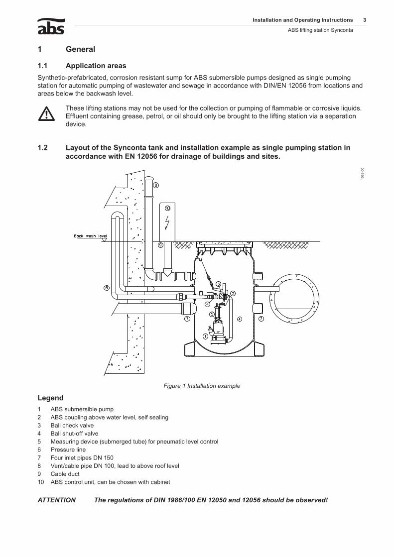
Figure 2 Installation example shows version with manhole cover suitable for light vehicular traffic.
L�������1 ABS submersible pump 6 Discharge line2 Synthetic collection tank 7 Cable duct3 Three DN 150 inlet ports, one DN 100 inlet port 8 Vent/cable pipe DN 100, lead to above roof level4 Ball shut-off valve 9 Control unit5 Ball check valve 10 Backwash level
L�������11
15-0
01 ABS Submersible pump2 Synthetic collection tank3 Two DN150/DN100 inlet ports4 Ball shut off valve5 Discharge line6 Vent/Cable pipe DN707 Backwash level
Figure 3 Installation of Synconta 601 above ground version
�������������������������������������� 5
ABS lifting station SyncontaABS lifting station Synconta
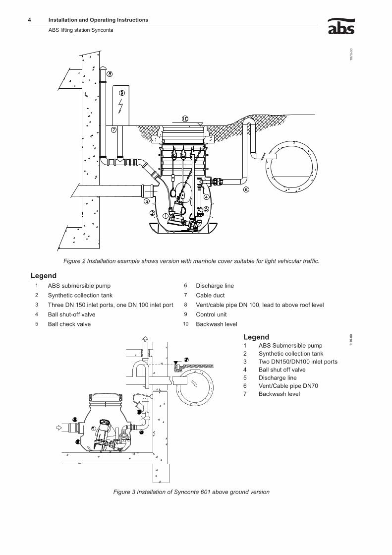
1.3 ABSh���h��v�����������w��h�����h�����������m�����������.(Sy������901-90����y)
L�������
1071
-00
The ABS high level coupling ensures a quick and easy installation. The special connection unit with coupling piece is installed and secured in the sump together with the valves before the sump itself is installed. The complete pump unit is lowered with a chain by hand down the guide tube. The unit automatically aligns and locates itself in the correct position, effecting a seal on the ABS high level discharge coupling, without the need to enter the sump. This automatic coupling process is especially useful where checking or inspection work is needed. The pump unit can be lifted out and lowered down even if the sump is flooded
A Bracket fixed installationB Guide tubeC Bracket with guide clawsD Chain to withdraw and lower pump for inspectionE Ball-type non-return valveF Shut-off valveG Discharge line connection G 2”H Flushing connection J Pneumatic level control
Figure 4 ABS high level coupling with discharge pipe pump suspension
1.4 C�mm�����y���h�������D�NEN��������������v�������h�����f��f�������������f���h�pumping of effluent containing faecal matter.
Automatically operated lifting stations are prescribed if:
the water level in the odour lock of the effluent source lies below the sewer backwash level.
rainwater gullies are present where the upper edge of the inlet grid lies below the sewer backwash level.
The sewer backwash level is the maximum possible water level in the public sewer network. Information on this can be obtained from your local authority. If the backwash level has not been fixed by the local authority, then the surface level of the roadway at the connection point is taken to be the level. The regulations also require that all waste-water which can cause offensive odours must be collected in closed, odour-tight, and free-standing collection tanks. The collection tanks must be vented by vent pipes which are brought above roof level.
1.5 D����������The fully equipped prefabricated synthetic Synconta tank can be used where a medium amount or steady flow of waste water is present. The Synconta is intended for waste water disposal in buildings, which are built below the back-flow and cannot depend on the natural gradient to allow the waste water to flow directly into the sewage system. The tank is installed outside the building on open ground and is an effective, quick and economical solution to the sewage problems of the contractor and architect. Suitable for vehicular traffic if used with appropriate lid. The Synconta 901 is suitable for installations according to DIN EN 124 Group 1 permissible traffic tonnage 5 kN/m2. Maximum permissible outside pressure 0.4 bar.
-
-
6 ��������������������������������������
ABS lifting station Synconta
� S�f��yThe general and specific health and safety hints are described in detail in the separate booklet Safety Hints. If anything is not clear or you have any questions as to safety make certain to contact the manufacturer ABS.
3 T��������
m During transport the unit should not be dropped or thrown.
4 S��-������������������
4.1 �������������f�h��������������kThe inlet lines must be laid in such a manner that there is a continuous fall of the prescribed magnitude to the inlet ports of the collection tank.
ATTENTION Theregulationsforundergroundengineeringworkshouldbeobserved.
The pit must be approximately 30 cm deeper than the unit and care taken that no soil can slide back in. The pit is to be filled with sand (grain size up to 2 mm) up to the point where the unit is installed.
ATTENTION Theunitissecuredagainstfloatingup,uptoawatertableof0,5mabovethetankfloor.Ifthewatertableishigher,additionalprotectionagainstfloatingupisnecessary.Thiscanachievedbysettingthebottomareaofthetankinconcrete.(seeFig.5)
Lower the unit into the pit and align on the prepared foundation.
NOTE Thefoundationmustbefreeofstoneorotherlargeobjects.Additionalfillingmayberequired.
Fill the pit with sand to the upper edge of the tank bottom. Put on tank cover, connect inlet ports and discharge lines.
4.� ���������f�h��������������k����������Only open inlet ports that are to be used. Only saw off as little as possible so that as much neck as possible is left for the plug connection. (Note the notch on the port neck). File down sharp edge inside and outside.
�������������������������������������� �
ABS lifting station SyncontaABS lifting station Synconta
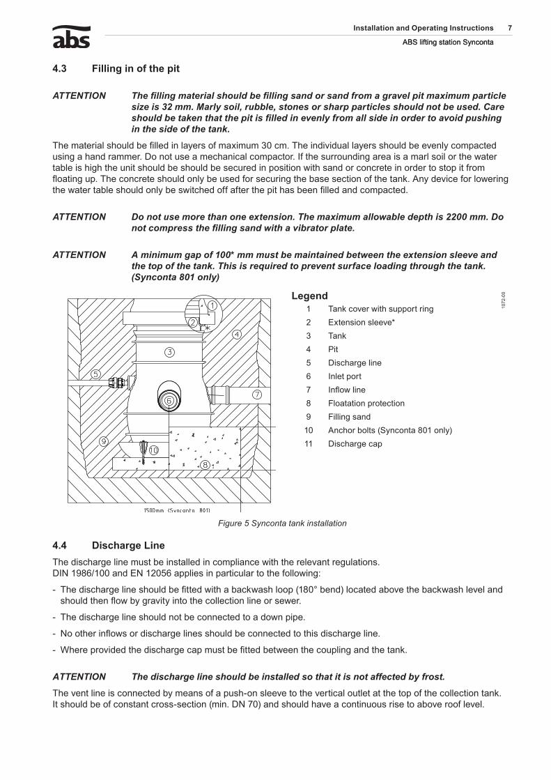
4.3 F����������f�h����
ATTENTION Thefillingmaterialshouldbefillingsandorsandfromagravelpitmaximumparticlesizeis32mm.Marlysoil,rubble,stonesorsharpparticlesshouldnotbeused.Careshouldbetakenthatthepitisfilledinevenlyfromallsideinordertoavoidpushinginthesideofthetank.
The material should be filled in layers of maximum 30 cm. The individual layers should be evenly compacted using a hand rammer. Do not use a mechanical compactor. If the surrounding area is a marl soil or the water table is high the unit should be should be secured in position with sand or concrete in order to stop it from floating up. The concrete should only be used for securing the base section of the tank. Any device for lowering the water table should only be switched off after the pit has been filled and compacted.
ATTENTION Donotusemorethanoneextension.Themaximumallowabledepthis2200mm.Donotcompressthefillingsandwithavibratorplate.
ATTENTION Aminimumgapof100*mmmustbemaintainedbetweentheextensionsleeveandthetopofthetank.Thisisrequiredtopreventsurfaceloadingthroughthetank.(Synconta801only)
L�������
1072
-00
1 Tank cover with support ring2 Extension sleeve*3 Tank4 Pit5 Discharge line6 Inlet port7 Inflow line8 Floatation protection9 Filling sand10 Anchor bolts (Synconta 801 only)11 Discharge cap
Figure 5 Synconta tank installation
4.4 D���h�����L���The discharge line must be installed in compliance with the relevant regulations. DIN 1986/100 and EN 12056 applies in particular to the following:
The discharge line should be fitted with a backwash loop (180° bend) located above the backwash level and should then flow by gravity into the collection line or sewer.
The discharge line should not be connected to a down pipe.
No other inflows or discharge lines should be connected to this discharge line.
Where provided the discharge cap must be fitted between the coupling and the tank.
ATTENTION Thedischargelineshouldbeinstalledsothatitisnotaffectedbyfrost.
The vent line is connected by means of a push-on sleeve to the vertical outlet at the top of the collection tank. It should be of constant cross-section (min. DN 70) and should have a continuous rise to above roof level.
-
-
-
-
8 ��������������������������������������
ABS lifting station Synconta
4.5 L�v���������(Sy������901����90����y)The level control is a pneumatic device with a submerged tube for measuring and control line. (Plastic tube to control panel). The measuring vessel is built into the Synconta tank, the required switch and control units are mounted outside in the control unit.
ATTENTION Whenapplyastaticlevelcontrol(withoutcompressororaeration)theheightofthesubmergedtubeformeasuringshouldbeadjusted,sothatitis20cmabovethemiddleofthevoluteofthepump.Therunontime,setat30secondswhendelivered,istobesetsothatthesubmergetubemeasuringisemptywhenthepumpisswitchedoff.
4.6 �������������f�h������������
ATTENTION Thecontrolunitshouldbefittedabovepossiblefloodlevelinawellventilatedroomandinaneasilyaccessibleposition.ProtectionClassofthecontrolunitIP54.
The control unit should be secured at all fixing points. The fixing holes are accessible after unscrewing the lower housing cover.
ATTENTION Donotdrillthroughthehousingofthecontrolunititself.
NOTE Themountinglocationofthecontrolunitshouldbechoseninsuchamannerthatthecontrollinerisesinacontinuousmannertothecontrolunit.Thecontrollinemustnotbekinked.
NOTE Anumberofdifferentcontrolboxmodelsexist.Pleasecheckthewiringdiagram/instructionmanualinthecontrolbox.
5 C�mm����������
m The safety hints in the previous sections must be observed!
Before commissioning the unit should be checked and a functional test carried out. Particular attention should be paid to the following:
Have the electrical connections been carried out in accordance with regulations?
Have the thermal sensors been connected?
Is the seal monitoring device (where fitted) correctly installed?
Is the motor overload switch correctly set?
Have the power and control circuit cables been correctly fitted?
Was the sump cleaned out?
Have the inflow and outflows of the pump station been cleaned and checked?
Is the direction of rotation correct - even if run via an emergency generator?
Are the level controls functioning correctly?
Are the required gates valves (where fitted) open?
Do the non-return valves (where fitted) function easily?
Have the hydraulics been vented in the case of dry installed pumps?
-
-
-
-
-
-
-
-
-
-
-
-
�������������������������������������� 9
ABS lifting station SyncontaABS lifting station Synconta
ATTENTION Beforecommissioningthecollectiontankshouldbecleanedofanylargeparticlesandfilledwithwater.Ifthecontrolline(rubberhose)wasconnectedtotheretainingpipeafterthecollectiontankwasfittedthecollectiontankhastobeemptiedmanuallyoncebysettingtheselectorswitch“Hand”.Aftercommissioningtheliftingunitisnormallyoperatedwiththeselectorswitchinposition“Auto”.
6 M����������
c Before commencing any maintenance work the unit should be completely disconnected from the mains by a qualified person and care should be taken that it cannot be inadvertently switched back on.
m When carrying out any repair or maintenance work, the safety regulations covering work in enclosed areas of sewage installations as well as good general technical pratices should be followed.
NOTE Themaintenancehintsgivenherearenotdesignedfor“do-it-yourself”repairsasspecialtechnicalknowledgeisrequired.
NOTE Amaintenancecontractwithourworksservicedepartmentwillguaranteeyouthebesttechnicalserviceunderallcircumstances.
6.1 C�mm�����y��m�����������f��f��������������������������w��hEN1�056It is recommended that the lifting station be inspected monthly and its function checked. In accordance with EN regulations, the lifting station should be maintained by a qualified person at the following intervals:
in commercial premises - every three months.
in apartment blocks - every six months.
in a single family home - once a year.
In addition we recommend that a maintenance contract be taken out with a qualified company.
6.� G������m����������h����ABS submersible pumps are reliable quality products each being subjected to careful final inspection. Lubricated-for-life ball bearings together with monitoring devices ensure optimum pump reliability provided that the pump has been connected and operated in accordance with the operating instructions. Should, nevertheless, a malfunction occur, do not improvise but ask your ABS customer service department for assistance. This applies particularly if the unit is continually switched off by the current overload in the control panel, by the thermal sensors of the thermo-control system or by the seal monitoring system (DI). Regular inspection and care is recommended to ensure a long service life.
NOTE TheABSserviceorganisationwouldbepleasedtoadviseyouonanyapplicationsyoumayhaveandtoassistyouinsolvingyourpumpingproblems.
NOTE TheABSwarrantyconditionsareonlyvalidprovidedthatanyrepairworkhasbeencarriedoutinABSapprovedworkshopandwhereoriginalABSsparepartshavebeenused.
-
-
-

ABS Production Wexford Ltd., Clonard Road, Wexford, Ireland Tel. +353 53 91 63 200 Fax +353 53 91 42335. www.absgroup.com