Embed Size (px)
Citation preview
www.absgroup.com
ABS lifting station Sanimat
1030
-00
1597
0299
GB
(10/
2006
)
Installation and Operating InstructionsGB
� ������������ ���� ���������� ��������������������������������������������������
ABS lifting station Sanimat
ABS reserves the right to alter specifications due to technical developments
C�������1 G������................................................................................................................................................... 3
1.1 Application areas ..................................................................................................................................... 3
1.2 Technical Data ......................................................................................................................................... 3
1.3 Nameplate ............................................................................................................................................... 3
1.4 Design of the faecal lifting station ........................................................................................................... 4
1.5 Description .............................................................................................................................................. 5
� S�f��y..................................................................................................................................................... 5
3 T��������................................................................................................................................................ 5
4 M������������������������..................................................................................................................... 6
4.1 Site requirements .................................................................................................................................... 7
4.2 Installation of the collection tank ............................................................................................................. 7
4.3 Opening of the collection tank inlet ports ................................................................................................ 8
4.4 Discharge Line ........................................................................................................................................ 8
4.5 Installation of the submersible pump ....................................................................................................... 9
4.5.1 Mounting of the volute support ................................................................................................................ 9
4.5.2 Installation of the pump head support ..................................................................................................... 9
4.6 Level Control ......................................................................................................................................... 10
4.7 Installation of the control unit ................................................................................................................ 11
4.8 Electrical Connection ............................................................................................................................ 11
4.9 Wiring Diagram ..................................................................................................................................... 12
4.10 Checking direction of rotation ................................................................................................................ 13
4.11 Installation of the accessories ............................................................................................................... 13
4.11.1 Installation of the Hand Membrane Pump (wall mounted) .................................................................... 13
5 C�mm����������................................................................................................................................... 14
6 M����������........................................................................................................................................ 14
6.1 Commentary on maintenance of Lifting Stations in accordance with EN 12056. .................................. 14
6.2 General maintenance hints ................................................................................................................... 15
6.3 Oil filling and Oil changing ..................................................................................................................... 15
6.4 Cleaning of level control pipe ................................................................................................................ 15
ABSL�f������������S���m��15013702
�������������������������������������� 3
ABS lifting station Sanimat
1 G������
1.1 A���������������
m These lifting stations may not be used for the collection or pumping of flammable or corrosive liquids. Effluent containing grease, petrol, or oil should only be brought to the lifting station via a separation device.
The flood-proof faecal lifting stations of the series Sanimat 1501S to 3702S have been designed for the pumping of sewage from locations below the sewer backwash level in accordance with EN 12056.
1.� T��h�����D���Maximum noise level ≤ 70 dB.
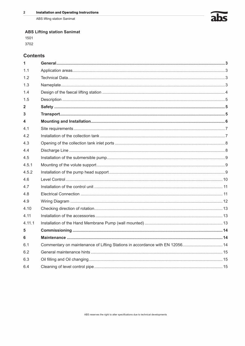
1.3 N�m������We recommend that you record the data from the original nameplate on the nameplate illustration below and maintain it, together with your purchase receipt, as a proof for subsequent use. Always state the pump type, item no. and serial no. in the field “Nr” in all Communications
L�������
1003
-00
Type Pump typeNr./SN Item No./Serial No.xx/xxxx Production date (Week/Year)UN Rated Voltage VIN Rated Current A
Frequency HzP1N Rated Input Power kWP2N Rated Output Power kWn Speed min-1Qmax Max. Flow m3/hHmax Max. Head mØ Imp. Impeller diameter mmDN Discharge diameter mmSS Water pressure tightIP 68 Protection type
Figure 1 Nameplate Standard Version
4 ��������������������������������������
ABS lifting station Sanimat
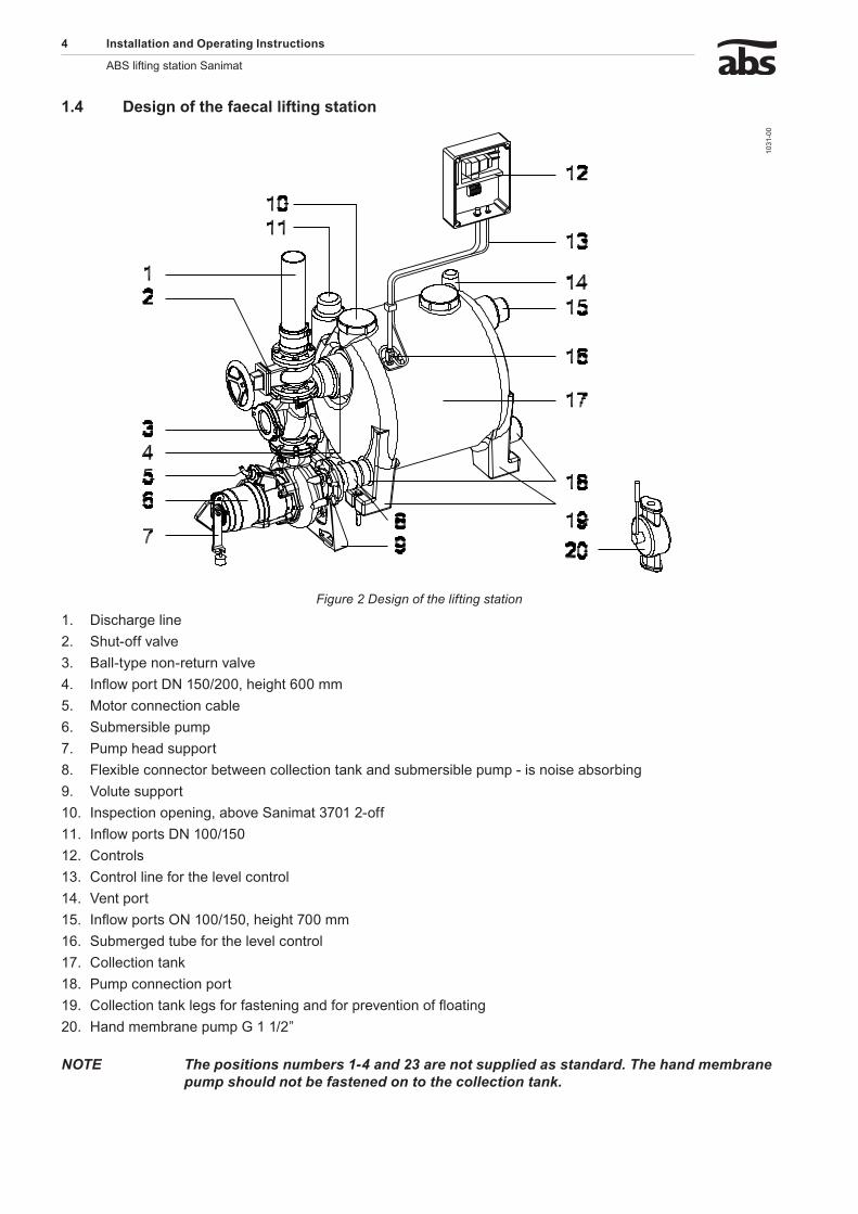
1.4 D�������f�h�f�������f������������
1031
-00
Figure 2 Design of the lifting stationDischarge lineShut-off valveBall-type non-return valveInflow port DN 150/200, height 600 mmMotor connection cableSubmersible pumpPump head supportFlexible connector between collection tank and submersible pump - is noise absorbingVolute supportInspection opening, above Sanimat 3701 2-offInflow ports DN 100/150ControlsControl line for the level controlVent portInflow ports ON 100/150, height 700 mmSubmerged tube for the level controlCollection tankPump connection portCollection tank legs for fastening and for prevention of floatingHand membrane pump G 1 1/2”
NOTE Thepositionsnumbers1-4and23arenotsuppliedasstandard.Thehandmembranepumpshouldnotbefastenedontothecollectiontank.
1.2.3.4.5.6.7.8.9.10.11.12.13.14.15.16.17.18.19.20.
�������������������������������������� 5
ABS lifting station Sanimat
1.5 D����������The flood-proof sewage lifting station Sanimat 1501S to 3702S are made up of a gas and odour-tight synthetic collection tank complying with DIN 19760 and 12050-1 with either 1 or 2 submersible sewage pumps, together with a control unit and level control system. The collection tank is fitted with a number of inflow ports. The unit is supplied from the factory with all inlet ports closed off. The inlet ports of dimensions DN 100/150 and 200 are located at various heights and can be opened up as required. Depending on the size of the sewage lifting station, submersible pumps of the types AS S17/2 and S26/2 as well as pumps from the AFP series M15/4 to M60/4 can be supplied. All motors comply with Insulation Class F (155 °C) and Protection Type IP 68. The motor shaft is supported in lubricated-for-life ball bearings. The shaft sealing on the motor side is carried out by a lip seal, while sealing at the liquid side is carried out by means of a high quality silicon carbide mechanical seal. The submersible pumps M15/4 to M60/4 have been supplied with thermal sensors in the stator which switch off the motors in the event of overheating, together with a Dl-system of moisture protection for the monitoring of the mechanical seal. The hydraulic section is supplied with ContraBlock system, and spiral bottom plate with waved shearing inlet, open ABS channel type impeller and volute. All hydraulic parts have been manufactured from Cast Iron (GG 25). The sewage entering by the inlet port is collected in the odour-tight collection tank. When a predetermined liquid level is reached, then the automatic level control system switches on the submersible pump and switches it off again when the tank is empty. In the case of twin pumping stations the starting sequence of pumps is reversed at each starting operation. If level 2 is reached, then both submersible pumps work in parallel. The automatic level control system functions as an electro-pneumatic control system based on the forced air bubbling principle, by which compressed air is continually pumped via the submerged tube into the liquid in the collection tank. The counter pressure caused by this is dependent on the liquid level present and operates a membrane switch in the control system by means of the control line (plastic hose). Units supplied with one pump can be retrofitted with a second pump.
� S�f��yThe general and specific health and safety hints are described in detail in the separate booklet Safety Hints. If anything is not clear or you have any questions as to safety make certain to contact the manufacturer ABS.
3 T��������
m During transport the unit should not be dropped or thrown.
c The unit should never be raised or lowered by the Power cable.
m Any hoist used must be adequately dimensioned for the weight of the unit.
All relevant safety regulators as well as general good technical practice must be complied with.
6 ��������������������������������������
ABS lifting station Sanimat
4 M������������������������
NOTE WerecommendthatoriginalABSinstallationaccessoriesbeusedformountingandinstallationoftheunit
m Particular attention must be paid to the safety regulations covering work in closed areas as well as good general technical practices.
1032
-00
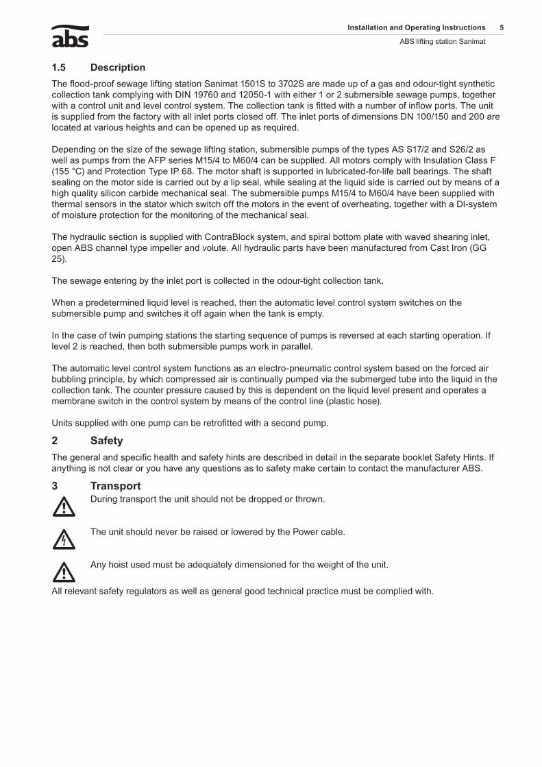
Figure 3 Installation example
L�������1 Vent Pipe (DN ≥70) above roof level 12 Hand membrane pump connection2 Control unit with level control system 13 Backwash loop with lowest point above the backwash level3 Power supply 14 Discharge line (DN100)4 Motor cable 15 Gate valve5 Twin control line for level control system 16 Non return valve6 Hand membrane pump 17 ABS submersible sewage pump7 Push on sleeve 18 Pump head support8 Gate valve 19 Seperate non return valve9 Sewage inflow DN150 20 Volute support10 Connection piece (push on piece) 21 Pump sump with dewatering pump (Robusta - Coronada)11 Sanimat collection tank
�������������������������������������� �
ABS lifting station Sanimat
4.1 S�����q����m����The rooms in which lifting stations are installed must be of adequate dimensions so that beside and over all control elements or items where maintenance might be required a working area of at least 60 cm width or height is available. Electrical supply to suit the submersible pumps being used.
NOTE Fusing,cablecross-sectionandvoltagedropofthepowerlinemustcomplywithDIN/ENandtherelevantelectricitysupplyboardregulations.
Any openings required in walls or ceilings for discharge, vent or inlet lines, must be of adequate dimensions so that the openings used can be sealed off using noise absorbing materials. The inlet lines must be laid in such a manner that there is a continuous fall of the prescribed magnitude to the inlet ports of the collection tank.
NOTE WheninstallingliftingstationsthenoiseprotectionregulationsinbuildingstoDIN4109shouldbeobserved.
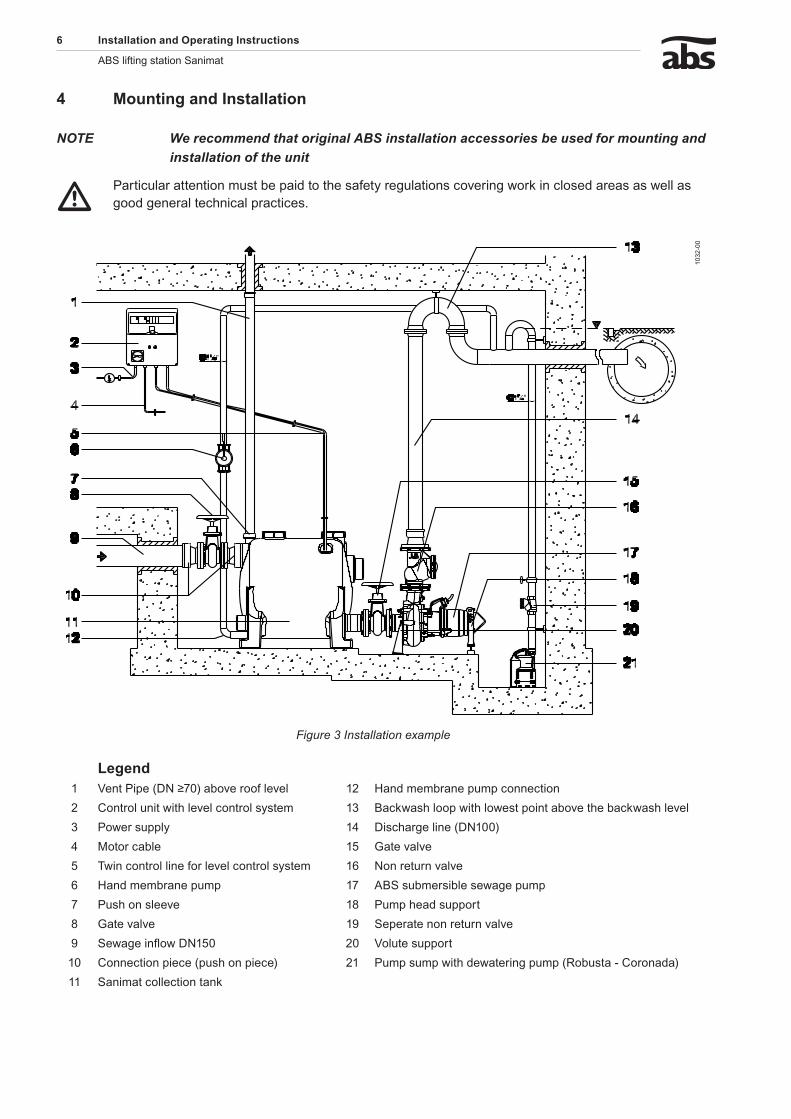
4.� �������������f�h��������������kDetermine the installation location and set-up the tank so that it is on level ground and horizontal in all directions. Secure the collection tank against movement or floating with the aid of plugs (3) hex screws (2) and washers (2).
ATTENTION Providealsoforlaterpositioningofthesubmersiblepumps.Thesubmersiblepumpsshouldbeinstalledonthegroundatthesamelevelasthecollectiontank.
ATTENTION Donotover-tightenhexscrew(2),orthecollectiontank(1)maybedamaged.
1033
-00
Figure 4 Bolting down of the collection tank
NOTE Hexagonheadwoodscrew10x130dowelsize12(notsupplied)
� ��������������������������������������
ABS lifting station Sanimat
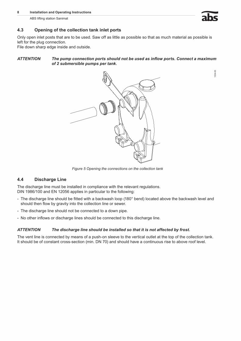
4.3 ���������f�h��������������k����������Only open inlet posts that are to be used. Saw off as little as possible so that as much material as possible is left for the plug connection. File down sharp edge inside and outside.
ATTENTION Thepumpconnectionportsshouldnotbeusedasinflowports.Connectamaximumof2submersiblepumpspertank.
1034
-00
Figure 5 Opening the connections on the collection tank
4.4 D���h�����L���The discharge line must be installed in compliance with the relevant regulations. DIN 1986/100 and EN 12056 applies in particular to the following:
The discharge line should be fitted with a backwash loop (180° bend) located above the backwash level and should then flow by gravity into the collection line or sewer.
The discharge line should not be connected to a down pipe.
No other inflows or discharge lines should be connected to this discharge line.
ATTENTION Thedischargelineshouldbeinstalledsothatitisnotaffectedbyfrost.
The vent line is connected by means of a push-on sleeve to the vertical outlet at the top of the collection tank. It should be of constant cross-section (min. DN 70) and should have a continuous rise to above roof level.
-
-
-
�������������������������������������� �
ABS lifting station Sanimat
4.5 �������������f�h���bm����b����m�
4.5.1 M���������f�h�v������������
1035
-00
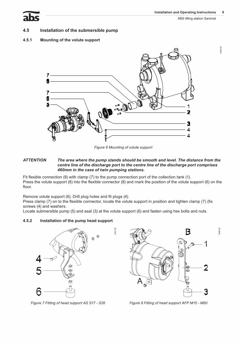
Figure 6 Mounting of volute support
ATTENTION Theareawherethepumpstandsshouldbesmoothandlevel.Thedistancefromthecentrelineofthedischargeporttothecentrelineofthedischargeportcomprises460mminthecaseoftwinpumpingstations.
Fit flexible connection (8) with clamp (7) to the pump connection port of the collection tank (1). Press the volute support (6) into the flexible connector (8) and mark the position of the volute support (6) on the floor. Remove volute support (6). Drill plug holes and fit plugs (4). Press clamp (7) on to the flexible connector, locate the volute support in position and tighten clamp (7) (fix screws (4) and washers. Locate submersible pump (5) and seal (3) at the volute support (6) and fasten using hex bolts and nuts.
4.5.� �������������f�h���m�h�����������
1047
-00
1048
-00
Figure 7 Fitting of head support AS S17 - S26 Figure 8 Fitting of head support AFP M15 - M60
10 ��������������������������������������
ABS lifting station Sanimat
S�bm����b����m��AFPM15,M��,M30,M40����M60
Locate vibration damper (3) at the pump head support (2). Fit the pump head support through ”Eyelet A” at the pump head. Adjust the vibration damper (3) so that the rubber support rests on the ground and fix the vibration damper (3) in position using hex nuts and washers. Submersible pumps AFP M40 and M60 Locate vibration damper (3) at the pump head support (2). The pump head support (2) is rotated by 180° and fitted via “Eyelet B” as shown in Figure 8. Set the vibration damper (3) so that the rubber support rests on the ground, and fix the vibration damper (3) in position using hex nuts and washers.
S�bm����b����m�ASS1�&S�6
Place the vibration damper (6) at the pump head support. Screw the pump head support (5) into the pump head using socket head screw (4). Adjust the vibration damper (6) in such a manner that the rubber support rests on the ground and fix the vibration damper (6) in position using hex nuts and washers.
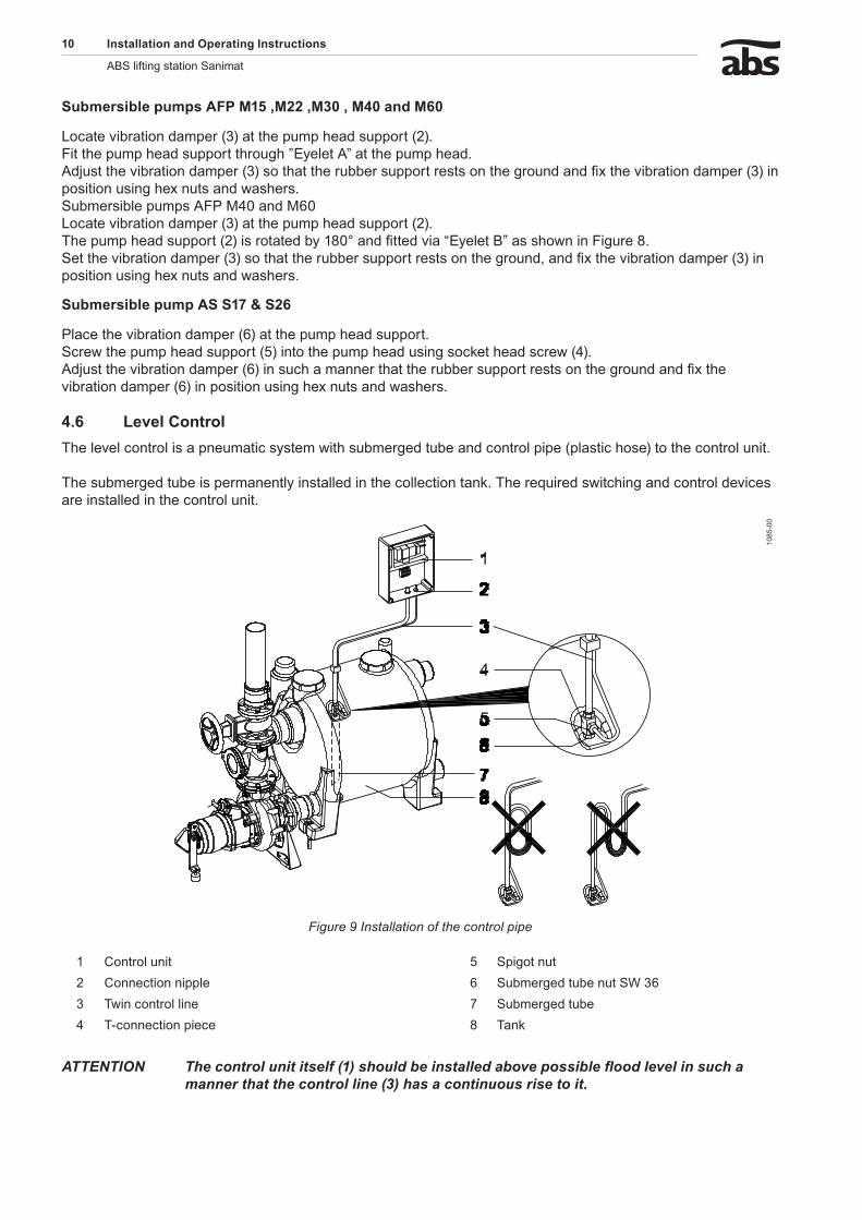
4.6 L�v��C������The level control is a pneumatic system with submerged tube and control pipe (plastic hose) to the control unit. The submerged tube is permanently installed in the collection tank. The required switching and control devices are installed in the control unit.
1085
-00
Figure 9 Installation of the control pipe
1 Control unit 5 Spigot nut2 Connection nipple 6 Submerged tube nut SW 363 Twin control line 7 Submerged tube4 T-connection piece 8 Tank
ATTENTION Thecontrolunititself(1)shouldbeinstalledabovepossiblefloodlevelinsuchamannerthatthecontrolline(3)hasacontinuousrisetoit.
�������������������������������������� 11
ABS lifting station Sanimat
Control line (3) has a continuous rise as shown in Figure 9. The control line should be shortened where necessary, pushed on to the hose nozzle of the submerged tube screw connector (5). The submerged tube screw connector (5) is prevented from turning by using an open ended spanner SW 13 and a spigot nut (4) is fully tightened.
ATTENTION Thesubmergedtubefixingscrew(5)shouldnotbetwisted.
4.� �������������f�h������������
ATTENTION Thecontrolunitshouldbefittedabovepossiblefloodlevelinawellventilatedroomandinaneasilyaccessibleposition.ProtectionClassofthecontrolunitIP54.
The control unit should be secured at all fixing points. The fixing holes are accessible after unscrewing the lower housing cover.
ATTENTION Donotdrillthroughthehousingofthecontrolunititself.
NOTE Themountinglocationofthecontrolunitshouldbechoseninsuchamannerthatthecontrollinerisesinacontinuousmannertothecontrolunit.Thecontrollinemustnotbekinked.
NOTE Anumberofdifferentcontrolboxmodelsexist.Pleasecheckthewiringdiagram/instructionmanualinthecontrolbox.
4.� E���������C���������
c Before commissioning an expert should check that one of the necessary electrical protective devices is available. Earthing, neutral, earth leakage circuit breakers, etc. must comply with the regulations of the local electricity supply authority and a qualified person should check that these are in perfect order.
ATTENTION ThepowersupplysystemonsitemustcomplywithVDEorotherlocalregulationswithregardtocross-sectionalareaandmaximumvoltagedrop.Thevoltagestatedonthenameplateofthepumpmustcorrespondtothatofthemains
The power supply cable must be protected by an adequately dimensioned slow-blow fuse corresponding to the rated power of the pump.
c The incoming power supply as well as the connection of the pump itself to the terminals on the control panel must comply with the circuit diagram of the control panel as well as the motor connection diagrams and must be carried out by a qualified person.
All relevant safety regulators as well as general good technical practice must be complied with.
NOTE Theoverloadrelayinthecontrolunithasbeencorrectlysetatthefactory.
NOTE Pleaseconsultyourelectrician.
1� ��������������������������������������
ABS lifting station Sanimat
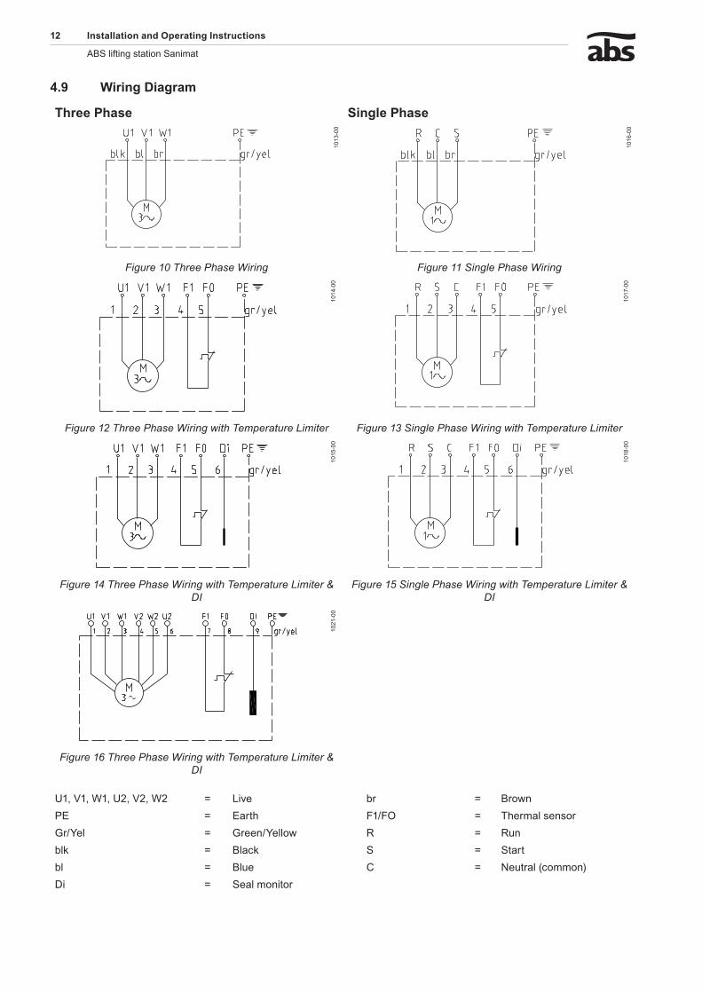
4.� W������D������m
Th���Ph��� S������Ph���
1013
-00
1016
-00
Figure 10 Three Phase Wiring Figure 11 Single Phase Wiring
1014
-00
1017
-00
Figure 12 Three Phase Wiring with Temperature Limiter Figure 13 Single Phase Wiring with Temperature Limiter
1015
-00
1018
-00
Figure 14 Three Phase Wiring with Temperature Limiter & DI
Figure 15 Single Phase Wiring with Temperature Limiter & DI
1021
-00
Figure 16 Three Phase Wiring with Temperature Limiter & DI
U1, V1, W1, U2, V2, W2 = Live br = BrownPE = Earth F1/FO = Thermal sensorGr/Yel = Green/Yellow R = Runblk = Black S = Startbl = Blue C = Neutral (common)Di = Seal monitor
�������������������������������������� 13
ABS lifting station Sanimat
4.10 Ch��k���������������f��������
m The safety hints in the previous sections must be observed!
When three phase units are being commissioned for the first time and also when used on a new site, the direction of rotation must be carefully checked by a qualified person.
c The direction of rotation should only be altered by a qualified person.
ATTENTION Thefollowingcharacteristicsofasubmersiblepumpindicateaprobableincorrectdirectionofrotation.
Submersible pump runs unevenly and vibrates strongly. Submersible pump does not achieve full output and the emptying times for the collection tank are too long. The submersible pump makes unusual running noises.
4.11 �������������f�h������������
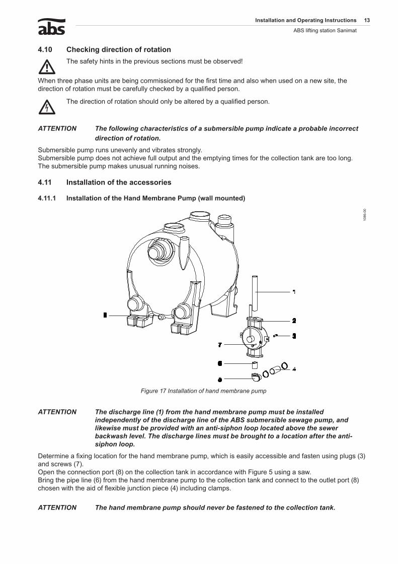
4.11.1 �������������f�h�H����M�mb����P�m�(w���m�������)
1086
-00
Figure 17 Installation of hand membrane pump
ATTENTION Thedischargeline(1)fromthehandmembranepumpmustbeinstalledindependentlyofthedischargelineoftheABSsubmersiblesewagepump,andlikewisemustbeprovidedwithananti-siphonlooplocatedabovethesewerbackwashlevel.Thedischargelinesmustbebroughttoalocationaftertheanti-siphonloop.
Determine a fixing location for the hand membrane pump, which is easily accessible and fasten using plugs (3) and screws (7). Open the connection port (8) on the collection tank in accordance with Figure 5 using a saw. Bring the pipe line (6) from the hand membrane pump to the collection tank and connect to the outlet port (8) chosen with the aid of flexible junction piece (4) including clamps.
ATTENTION Thehandmembranepumpshouldneverbefastenedtothecollectiontank.
14 ��������������������������������������
ABS lifting station Sanimat
5 C�mm����������
m The safety hints in the previous sections must be observed!
Before commissioning the unit should be checked and a functional test carried out. Particular attention should be paid to the following:
Have the electrical connections been carried out in accordance with regulations?
Is the direction of rotation correct - even if run via an emergency generator?
Was the control line (plastic hose) laid in such a manner that it has a continuous rise?
Was the collection tank secured against floating?
Has venting been installed in accordance with the regulations?
ATTENTION Beforecommissioningthecollectiontankshouldbecleanedofanylargeparticlesandfilledwithwater.Ifthecontrolline(plastichose)wasconnectedtothesubmergedtubewiththetankalreadyfull,thenthecollectiontankmustbefullyemptiedoncebyactivationoftheselectorswitch“Hand”.Aftercommissioningthefaecalliftingstationisnormallyoperatedwiththeselectorswitchinposition“Auto”.
6 M����������
c Before commencing any maintenance work the unit should be completely disconnected from the mains by a qualified person and care should be taken that it cannot be inadvertently switched back on.
m When carrying out any repair or maintenance work, the safety regulations covering work in enclosed areas of sewage installations as well as good general technical pratices should be followed.
NOTE Themaintenancehintsgivenherearenotdesignedfor“do-it-yourself”repairsasspecialtechnicalknowledgeisrequired.
NOTE Amaintenancecontractwithourworksservicedepartmentwillguaranteeyouthebesttechnicalserviceunderallcircumstances.
6.1 C�mm�����y��m�����������fL�f�����S��������������������w��hEN1�056.It is recommended that the lifting station be inspected monthly and its function checked.
In accordance with EN regulations, the lifting station should be maintained by a qualified person at the following intervals:
in commercial premises - every three months.
in apartment blocks - every six months.
in a single family home - once a year.
In addition we recommend that a maintenance contract be taken out with a qualified company.
-
-
-
-
-
-
-
-
-
�������������������������������������� 15
ABS lifting station Sanimat
6.� G������m����������h����ABS lifting stations are reliable quality products each being subjected to careful final inspection. Lubricated-for-life ball bearings together with monitoring devices ensure optimum pump reliability provided that the pump has been connected and operated in accordance with the operating instructions. Should, nevertheless, a malfunction occur, do not improvise but ask your ABS customer service department for assistance. This applies particularly if the unit is continually switched off by the current overload in the control panel, by the thermal sensors of the thermo-control system or by the seal monitoring system (DI). Regular inspection and care is recommended to ensure a long service life.
NOTE TheABSserviceorganisationwouldbepleasedtoadviseyouonanyapplicationsyoumayhaveandtoassistyouinsolvingyourpumpingproblems.
NOTE TheABSwarrantyconditionsareonlyvalidprovidedthatanyrepairworkhasbeencarriedoutinABSapprovedworkshopandwhereoriginalABSsparepartshavebeenused.
6.3 OilfillingandOilchangingWaste oil must be disposed of in the proper manner.
6.4 C���������f��v�������������It is recommended that the level control pipe be examined monthly to ensure that no build up of solids occurs inside the pipe, thus preventing accurate level control of the lifting station. Build-up of solids inside the pipe can cause continuos pumping, no pumping or inaccurate switching levels. The pipe can be pulled out of the tank and cleaned, rinsed and replaced. It should be greased as it is put back in.

ABS Production Wexford Ltd., Clonard Road, Wexford, Ireland Tel. +353 53 91 63 200 Fax +353 53 91 42335. www.absgroup.com